chapter 6, solution 1 - wordpress.com · chapter 12, solution 9. = + ∠ ° = + = 20 j15 120 0 l y...
TRANSCRIPT

Chapter 12, Solution 1.
(a) If , then 400ab =V
=°∠= 30-3
400anV V30-231 °∠
=bnV V150-231 °∠ =cnV V270-231 °∠
(b) For the acb sequence,
°∠−°∠=−= 120V0V ppbnanab VVV
°∠=
−+= 30-3V
23
j21
1V ppabV
i.e. in the acb sequence, lags by 30°. abV anV Hence, if , then 400ab =V
=°∠= 303
400anV V30231 °∠
=bnV V150231 °∠ =cnV V90-231 °∠
Chapter 12, Solution 2.
Since phase c lags phase a by 120°, this is an acb sequence.
=°+°∠= )120(30160bnV V150160 °∠ Chapter 12, Solution 3. Since V leads by 120°, this is an bn cnV abc sequence.
=°+°∠= )120(130208anV V250208 °∠

Chapter 12, Solution 4.
=°∠= 120cabc VV V140208 °∠
=°∠= 120bcab VV V260208 °∠
=°∠°∠
=°∠
=303260208
303ab
an
VV V230120 °∠
=°∠= 120-anbn VV V110120 °∠
Chapter 12, Solution 5. This is an abc phase sequence.
°∠= 303anab VV
or =°∠°∠
=°∠
=3030420
303ab
an
VV V30-5.242 °∠
=°∠= 120-anbn VV V150-5.242 °∠
=°∠= 120ancn VV V905.242 °∠
Chapter 12, Solution 6.
°∠=+= 26.5618.115j10YZ The line currents are
=°∠
°∠==
26.5618.110220
Y
ana Z
VI A26.56-68.19 °∠
=°∠= 120-ab II A146.56-68.19 °∠
=°∠= 120ac II A93.4468.19 °∠

The line voltages are
=°∠= 303200abV V30381 °∠ =bcV V90-381 °∠ =caV V210-381 °∠
The load voltages are
=== anYaAN VZIV V0220 °∠ == bnBN VV V120-220 °∠ == cnCN VV V120220 °∠
Chapter 12, Solution 7. This is a balanced Y-Y system.
+ − 440∠0° V ZY = 6 − j8 Ω
Using the per-phase circuit shown above,
=−
°∠=
8j60440
aI A53.1344 °∠
=°∠= 120-ab II A66.87-44 °∠ =°∠= 120ac II A13.73144 °∠
Chapter 12, Solution 8. , V220VL = Ω+= 9j16YZ
°∠=+
=== 29.36-918.6)9j16(3
2203VV
Y
L
Y
pan ZZ
I
=LI A918.6

Chapter 12, Solution 9.
=+
°∠=
+=
15j200120
YL
ana ZZ
VI A36.87-8.4 °∠
=°∠= 120-ab II A156.87-8.4 °∠
=°∠= 120ac II A83.138.4 °∠
As a balanced system, =nI A0
Chapter 12, Solution 10. Since the neutral line is present, we can solve this problem on a per-phase basis.
For phase a,
°∠=−
°∠=
+= 36.5355.6
20j270220
2A
ana Z
VI
For phase b,
°∠=°∠
=+
= 120-1022
120-2202B
bnb Z
VI
For phase c,
°∠=+
°∠=
+= 97.3892.16
5j12120220
2C
cnc Z
VI
The current in the neutral line is
)-( cban IIII ++= or cban- IIII ++=
)78.16j173.2-()66.8j5-()9.3j263.5(- n ++−++=I
=−= 02.12j91.1nI A81-17.12 °∠

Chapter 12, Solution 11.
°∠°∠
=°∠
=°∠
=90-3
1022090-390-3
BCbcan
VVV
=anV V100127 °∠
=°∠= 120BCAB VV V130220 °∠
V110-220120-BCAC °∠=°∠= VV
If , then °∠= 6030bBI
°∠= 18030aAI , °∠= 60-30cCI
°∠=°∠°∠
=°∠
= 21032.1730-3
1803030-3
aAAB
II
°∠= 9032.17BCI , °∠= 30-32.17CAI
== CAAC -II A15032.17 °∠
BCBC VZI =
=°∠
°∠==
9032.170220
BC
BC
IV
Z Ω°∠ 80-7.12
Chapter 12, Solution 12. Convert the delta-load to a wye-load and apply per-phase analysis.
Ia
110∠0° V + −
ZY
Ω°∠== ∆ 45203Y
ZZ

=°∠°∠
=45200110
aI A45-5.5 °∠
=°∠= 120-ab II A165-5.5 °∠ =°∠= 120ac II A755.5 °∠
Chapter 12, Solution 13.
First we calculate the wye equivalent of the balanced load.
ZY = (1/3)Z∆ = 6+j5
Now we only need to calculate the line currents using the wye-wye circuits.
A07.58471.615j8120110I
A07.178471.615j8120110I
A93.61471.65j610j2
110I
c
b
a
°∠=+
°∠=
°∠=+
°−∠=
°−∠=+++
=

Chapter 12, Solution 14. We apply mesh analysis. Ω+ 2j1 A a + ZL 100 ZV 0o∠ L - I3 n I1 B C - -
100 + - + c I
V 120100 o∠ V 120o∠ Ω+= 1212 jZ L
2 b Ω+ 2j1 Ω+ 2j1 For mesh 1,
0)1212()21()1614(120100100 321 =+−+−++∠+− IjIjjIo or
6.861506.8650100)1212()21()1614( 321 jjIjIjIj −=−+=+−+−+ (1) For mesh 2,
0)1614()1212()21(120100120100 231 =+++−+−−∠−∠ IjIjjIoo or
2.1736.86506.8650)1212()1614()21( 321 jjjIjIjIj −=−+−−=+−+++− (2) For mesh 3,
0)3636()1212()1212( 321 =+++−+− IjIjIj (3) Solving (1) to (3) gives
016.124197.4,749.16098.10,3.19161.3 321 jIjIjI −−=−−=−−= A 3.9958.191
oaA II −∠==
A 8.159392.712
obB III ∠=−=
A 91.5856.192
ocC II ∠=−=

Chapter 12, Solution 15.
Convert the delta load, , to its equivalent wye load. ∆Z
10j83Ye −== ∆Z
Z
°∠=−
−+== 14.68-076.8
5j20)10j8)(5j12(
|| YeYp ZZZ
047.2j812.7p −=Z
047.1j812.8LpT −=+= ZZZ
°∠= 6.78-874.8TZ
We now use the per-phase equivalent circuit.
Lp
pa
VZZ
I+
= , where 3
210pV =
°∠=°∠
= 78.666.13)6.78-874.8(3
210aI
== aL II A66.13
Chapter 12, Solution 16.
(a) °∠=°+°∠== 15010)180-30(10- ACCA II This implies that °∠= 3010ABI
°∠= 90-10BCI
=°∠= 30-3ABa II A032.17 °∠ =bI A120-32.17 °∠ =cI A12032.17 °∠
(b) =°∠°∠
==∆ 30100110
AB
AB
IV
Z Ω°∠ 30-11

Chapter 12, Solution 17. Convert the ∆-connected load to a Y-connected load and use per-phase analysis.
Ia
+ −
ZL
Van ZY
4j33Y +== ∆Z
Z
°∠=+++°∠
=+
= 48.37-931.19)5.0j1()4j3(
0120
LY
ana ZZ
VI
But °∠= 30-3ABa II
=°∠
°∠=
30-348.37-931.19
ABI A18.37-51.11 °∠
=BCI A138.4-51.11 °∠ =CAI A101.651.11 °∠
)53.1315)(18.37-51.11(ABAB °∠°∠== ∆ZIV
=ABV V76.436.172 °∠
=BCV V85.24-6.172 °∠ =CAV V8.5416.172 °∠
Chapter 12, Solution 18.
°∠=°∠°∠=°∠= 901.762)303)(60440(303anAB VV
°∠=+=∆ 36.87159j12Z

=°∠°∠
==∆ 36.8715
901.762ABAB Z
VI A53.1381.50 °∠
=°∠= 120-ABBC II A66.87-81.50 °∠
=°∠= 120ABCA II A173.1381.50 °∠ Chapter 12, Solution 19.
°∠=+=∆ 18.4362.3110j30Z The phase currents are
=°∠
°∠==
∆ 18.4362.310173ab
AB ZV
I A18.43-47.5 °∠
=°∠= 120-ABBC II A138.43-47.5 °∠ =°∠= 120ABCA II A101.5747.5 °∠
The line currents are
°∠=−= 30-3ABCAABa IIII
=°∠= 48.43-347.5aI A48.43-474.9 °∠
=°∠= 120-ab II A168.43-474.9 °∠ =°∠= 120ac II A71.57474.9 °∠
Chapter 12, Solution 20.
°∠=+=∆ 36.87159j12Z The phase currents are
=°∠
°∠=
36.87150210
ABI A36.87-14 °∠
=°∠= 120-ABBC II A156.87-14 °∠ =°∠= 120ABCA II A83.1314 °∠
The line currents are
=°∠= 30-3ABa II A66.87-25.24 °∠ =°∠= 120-ab II A186.87-25.24 °∠
=°∠= 120ac II A53.1325.24 °∠

Chapter 12, Solution 21.
(a) )rms(A66.9896.1766.38806.12
1202308j10
120230IAC °−∠=°∠
°∠−=
+°∠−
=
(b)
A34.17110.31684.4j75.30220.11j024.14536.6j729.16
66.3896.1766.15896.178j100230
8j10120230IIIII ABBCBABCbB
°∠=+−=+−−−=
°−∠−°−∠=+
°∠−
+−∠
=−=+=
Chapter 12, Solution 22.
Convert the ∆-connected source to a Y-connected source.
°∠=°∠=°∠= 30-12030-3
20830-
3
VpanV
Convert the ∆-connected load to a Y-connected load.
j8)5j4)(6j4(
)5j4(||)6j4(3
||Y +−+
=−+== ∆ZZZ
2153.0j723.5 −=Z
Ia
+ −
ZL
Van Z
=−
°∠=
+=
2153.0j723.730120
L
ana ZZ
VI A28.4-53.15 °∠
=°∠= 120-ab II A148.4-53.15 °∠
=°∠= 120ac II A91.653.15 °∠

Chapter 12, Solution 23.
(a) oAB
AB ZVI
6025208∠
==∆
o
o
oo
ABa II 90411.146025
303208303 −∠=∠
−∠=−∠=
A 41.14|| == aL II
(b) kW 596.260cos25
3208)208(3cos321 =
==+= o
LL IVPPP θ
Chapter 12, Solution 24. Convert both the source and the load to their wye equivalents.
10j32.1730203Y +=°∠== ∆Z
Z
°∠=°∠= 02.24030-3ab
an
VV
We now use per-phase analysis.
Ia
+ −
1 + j Ω
Van 20∠30° Ω
=°∠
=+++
=3137.212.240
)10j32.17()j1(an
a
VI A31-24.11 °∠
=°∠= 120-ab II A151-24.11 °∠
=°∠= 120ac II A8924.11 °∠

But °∠= 30-3ABa II
=°∠°∠
=30-331-24.11
ABI A1-489.6 °∠
=°∠= 120-ABBC II A121-489.6 °∠
=°∠= 120ABCA II A119489.6 °∠
Chapter 12, Solution 25.
Convert the delta-connected source to an equivalent wye-connected source and consider the single-phase equivalent.
Ya 3
)3010(440Z
I°−°∠
=
where °°∠=−=−++= 78.24-32.146j138j102j3YZ
=°∠
°∠=
)24.78-32.14(320-440
aI A4.7874.17 °∠
=°∠= 120-ab II A115.22-74.17 °∠
=°∠= 120ac II A124.7874.17 °∠
Chapter 12, Solution 26. Transform the source to its wye equivalent.
°∠=°∠= 30-17.7230-3
VpanV
Now, use the per-phase equivalent circuit.
ZV
I anaA = , °∠=−= 32-3.2815j24Z

=°∠°∠
=32-3.2830-17.72
aAI A255.2 °∠
=°∠= 120-aAbB II A118-55.2 °∠
=°∠= 120aAcC II A12255.2 °∠
Chapter 12, Solution 27.
)15j20(310-220
330-
Y
aba +
°∠=
°∠=
ZV
I
=aI A46.87-081.5 °∠
=°∠= 120-ab II A166.87-081.5 °∠
=°∠= 120ac II A73.13081.5 °∠
Chapter 12, Solution 28. Let °∠= 0400abV
°∠=°∠°∠
=°∠
= 307.7)60-30(3
30-4003
30-
Y
ana Z
VI
== aLI I A7.7
°∠=°∠== 30-94.23030-3an
YaAN
VZIV
== ANpV V V9.230

Chapter 12, Solution 29.
, θ= cosIV3P pp 3V
V Lp = , pL II =
θ= cosIV3P LL
pL
L I05.20)6.0(3240
5000cosV3
PI ===
θ=
911.6)05.20(3
240I3
VIV
L
L
p
pY ====Z
°=θ→=θ 13.536.0cos
(leading)53.13-911.6Y °∠=Z
=YZ Ω− 53.5j15.4
83336.0
5000pfP
S ===
6667sinSQ =θ=
=S VA6667j5000−
Chapter 12, Solution 30.
Since this a balanced system, we can replace it by a per-phase equivalent, as shown below. + ZL Vp
-

3,33 *
2L
pp
pp
VVZVSS ===
kVA 454421.14530)208( 2
*
2o
op
L
ZVS ∠=
−∠==
kW 02.1cos == θSP
Chapter 12, Solution 31.
(a) kVA 5.78.0/6cos
,8.0cos,000,6 =====θ
θ Ppp
PSP
kVAR 5.4sin == θPp SQ
kVA 5.1318)5.46(33 jjSS p +=+== For delta-connected load, Vp = VL= 240 (rms). But
Ω+=+
==→= 608.4144.6,10)5.1318(
)240(3333
22*
*
2
jZxjS
VZZVS P
pp
p
p
(b) A 04.188.02403
6000cos3 ==→=xx
IIVP LLLp θ
(c ) We find C to bring the power factor to unity
F 2.207240602
4500kVA 5.4 22 µπω
===→==xxV
QCQQrms
cpc
Chapter 12, Solution 32.
θ∠= LLIV3S
3LL 1050IV3S ×=== S
==)440(3
5000IL A61.65

For a Y-connected load,
61.65II Lp == , 03.2543
4403
VV L
p ===
872.361.6503.254
IV
p
p===Z
θ∠= ZZ , °==θ 13.53)6.0(cos-1
)sinj)(cos872.3( θ+θ=Z
)8.0j6.0)(872.3( +=Z
=Z Ω+ 098.3j323.2
Chapter 12, Solution 33. θ∠= LLIV3S
LLIV3S == S
For a Y-connected load,
pL II = , pL V3V =
pp IV3S =
====)208)(3(
4800V3S
IIp
pL A69.7
=×== 2083V3V pL V3.360

Chapter 12, Solution 34.
3
2203
VV L
p ==
°∠=−
== 5873.6)16j10(3
200V
Y
pa Z
I
== pL II A73.6
°∠××=θ∠= 58-73.62203IV3 LLS
=S VA8.2174j1359−
Chapter 12, Solution 35.
(a) This is a balanced three-phase system and we can use per phase equivalent circuit. The delta-connected load is converted to its wye-connected equivalent
10203/)3060(31'' jjZZ y +=+== ∆
IL
+ 230 V Z’y Z’’y
-
5.55.13)1020//()1040(//' '' jjjZZZ yyy +=++==
A 953.561.145.55.13
230 jj
I L −=+
=
(b) kVA 368.1361.3* jIVS Ls +== (c ) pf = P/S = 0.9261

Chapter 12, Solution 36.
(a) S = 1 [0.75 + sin(cos-10.75) ] =0.75 + 0.6614 MVA
(b) 49.5252.5942003
10)6614.075.0(3
36
** jx
xjVSIIVp
ppp +=+
==→=S
kW 19.25)4()36.79(|| 22 === lpL RIP
(c) kV 2.709-4.443 kV 21.04381.4)4( o∠=−=++= jjIV pLsV Chapter 12, Solution 37.
206.0
12pfP
S ===
kVA16j1220S −=θ∠=θ∠=S
But θ∠= LLIV3S
=××
=20831020
I3
L A51.55
p
2
p3 ZIS = For a Y-connected load, pL II = .
2
3
2
L
p )51.55)(3(10)16j12(
I3
×−==
SZ
=pZ Ω− 731.1j298.1

Chapter 12, Solution 38.
As a balanced three-phase system, we can use the per-phase equivalent shown below.
14j100110
)12j9()2j1(0110
a +°∠
=+++°∠
=I
)12j9()1410(
)110(21
21
22
2
Y
2
ap +⋅+
⋅== ZIS
The complex power is
)12j9(296
)110(23
32
p +⋅⋅== SS
=S VA81.735j86.551 +
Chapter 12, Solution 39. Consider the system shown below.
I2
I1I3
5 Ω
5 Ω
-j6 Ω
10 Ω
j3 Ω
B C
A
8 Ω
4 Ω
b
a
−+
+ −
100∠-120°
100∠120° 100∠0°− +
5 Ω
c
For mesh 1,
321 )6j8(5)6j18(100 III −−−−= (1) For mesh 2,
312 10520120-100 III −−=°∠
321 24-120-20 III −+=°∠ (2)

For mesh 3, 321 )3j22(10)6j8(-0 III −+−−= (3)
To eliminate , start by multiplying (1) by 2, 2I
321 )12j16(10)12j36(200 III −−−−= (4) Subtracting (3) from (4),
31 )15j38()18j44(200 II −−−= (5) Multiplying (2) by 45 ,
321 5.2525.1-120-25 III −+=°∠ (6) Adding (1) and (6),
31 )6j5.10()6j75.16(65.21j5.87 II −−−=− (7) In matrix form, (5) and (7) become
+−+−
=
− 3
1
6j5.10-6j75.1615j38-18j44
65.12j5.87200
II
25.26j5.192 −=∆ , 2.935j25.9001 −=∆ , 6.1327j3.1103 −=∆
144.4j242.538.33-682.67.76-28.194
46.09-1.129811 −=°∠=
°∠°∠
=∆∆
=I
694.6j485.177.49-857.67.76-28.194
85.25-2.133233 −=°∠=
°∠°∠
=∆∆
=I
We obtain from (6), 2I
312 21
41
120-5 III ++°∠=
)347.3j7425.0()0359.1j3104.1()33.4j-2.5(2 −+−+−=I
713.8j4471.0-2 −=I The average power absorbed by the 8-Ω resistor is
W89.164)8(551.2j756.3)8(P22
311 =+=−= II The average power absorbed by the 4-Ω resistor is
W1.188)4()8571.6()4(P 22
32 === I

The average power absorbed by the 10-Ω resistor is
W12.78)10(019.2j1.9321-)10(P 22323 =−=−= II
Thus, the total real power absorbed by the load is
=++= 321 PPPP W1.431 Chapter 12, Solution 40. Transform the delta-connected load to its wye equivalent.
8j73Y +== ∆Z
Z
Using the per-phase equivalent circuit above,
°∠=+++
°∠= 46.75-567.8
)8j7()5.0j1(0100
aI
For a wye-connected load,
567.8II aap === I
)8j7()567.8)(3(3 2p
2
p +== ZIS
=== )7()567.8)(3()Re(P 2S k541.1 W Chapter 12, Solution 41.
kVA25.68.0
kW5pfP
S ===
But LLIV3S =
=××
==40031025.6
V3S
I3
LL A021.9

Chapter 12, Solution 42. The load determines the power factor.
°=θ→==θ 13.53333.13040
tan
(leading)6.0cospf =θ=
kVA6.9j2.7)8.0(6.02.7
j2.7 −=
−=S
But p
2
p3 ZIS =
80)40j30)(3(
10)6.9j2.7(3
3
p
2
p =−
×−==
ZS
I
A944.8Ip =
== pL II A944.8
=×
==)944.8(3
1012I3
SV
3
LL V6.774
Chapter 12, Solution 43.
p
2
p3 ZIS = , Lp II = for Y-connected loads
)047.2j812.7()66.13)(3( 2 −=S =S kVA145.1j373.4 −

Chapter 12, Solution 44. For a ∆-connected load,
Lp VV = , pL I3I =
LLIV3S =
273.31)240(3
10)512(V3
SI
322
LL =
×+==
At the source,
LLL'L ZIVV +=
)3j1)(273.31(0240'L ++°∠=V
819.93j273.271'L +=V
='LV V04.287
Also, at the source,
*L
'L
' 3 IVS = )273.31)(819.93j273.271(3' +=S
078.19273.271
819.93tan 1- =
=θ
=θ= cospf 9451.0
Chapter 12, Solution 45. θ∠= LLIV3S
LL V3
-I
θ∠=
S, kVA6.635
708.010450
pfP 3
=×
==S
A45-8344403
-)6.635(L °∠=
×θ∠
=I
At the source,
)2j5.0(0440 LL ++°∠= IV
)76062.2)(45-834(440L °∠°∠+=V °∠+= 137.1719440LV
7.885j1.1914L +=V =LV V.8324109.2 °∠
Chapter 12, Solution 46. For the wye-connected load,
pL II = , pL V3V = Zpp VI =
*
2
L*
2
p*pp
3333
ZV
ZV
IVS ===
W121100
)110( 2
*
2
L ===Z
VS
For the delta-connected load,
Lp VV = , pL I3I = , Zpp VI =
*
2
L*
2
p*pp
333
ZV
ZV
IVS ===
W363100
)110)(3( 2
==S
This shows that the delta-connected load will deliver three times more average
power than the wye-connected load. This is also evident from 3Y∆=
ZZ .
Chapter 12, Solution 47.
°==θ→= 87.36)8.0(cos(lagging)8.0pf -1 kVA150j20087.362501 +=°∠=S
°==θ→= 19.18-)95.0(cos(leading)95.0pf -1
kVA65.93j28519.81-3002 −=°∠=S

°==θ→= 0)1(cos0.1pf -1
kVA4503 =S
kVA45.37.93635.56j935321T °∠=+=++= SSSS
LLT IV3=S
=××
=)108.13(3
107.936I
3
3
L rmsA19.39
=°=θ= )45.3cos(cospf (lagging)9982.0
Chapter 12, Solution 48.
(a) We first convert the delta load to its equivalent wye load, as shown below. A A ZA 18-j12Ω 40+j15Ω ZC C B C 60Ω
ZB
B
923.1577.73118
)1218)(1540( jjjjZ A −=
+−+
=
105.752.203118
).1540(60 jjjZ B −=
++
=
3303.6992.83118
)1218(60 jjjZC −=
+−
=
The system becomes that shown below.

a 2+j3 A + 240<0o ZA - I1 - - ZB ZC 240<120o 240<-120o + + 2+j3 c I2 b B C 2+j3
We apply KVL to the loops. For mesh 1, 0)()2(120240240 21 =+−+++−∠+− lBBAl
o ZZIZZZI or
85.207360)105.1052.22()13.11097.32( 21 jIjIj +=+−+ (1) For mesh 2,
0)2()(120240120240 21 =++++−−∠−∠ CBllBoo ZZZIZZI
or
69.415)775.651.33()105.1052.22( 21 jIjIj −=+++− (2) Solving (1) and (2) gives
89.11165.15,328.575.23 21 jIjI −=−=
A 6.14281.10,A 64.1234.24 121o
bBo
aA IIIII −∠=−=−∠==
A 9.14127.192o
cC II ∠=−= (b) ooo
aS 64.126.5841)64.1234.24)(0240( ∠=∠∠= ooo
bS 6.224.2594)6.14281.10)(120240( ∠=∠−∠= ooo
bS 9.218.4624)9.14127.19)(120240( −∠=−∠∠= kVA 54.24.12kVA 55.0386.12 o
cba jSSSS ∠=+=++=

Chapter 12, Solution 49.
(a) For the delta-connected load, (rms) 220,1020 ==Ω+= Lpp VVjZ ,
kVA 56.26943.629045808)1020(
22033 2
*
2o
p
p jj
xZVS ∠=+=
−==
(b) For the wye-connected load, 3/,1020 Lpp VVjZ =Ω+= ,
kVA 56.26164.2)1020(3
22033 2
*
2o
p
p
jx
ZVS ∠=
−==
Chapter 12, Solution 50.
kVA 3kVA, 4.68.4)8.06.0(8 121 =+=+=+= SjjSSS Hence,
kVA 4.68.112 jSSS +=−=
But p
LLp
p
p
ZVSVV
ZVS *
2
2*
2
2.
3,3
=→==
Ω+=→+
== 34.8346.210)4.68.1(
2403
2
2
** jZ
xjSVZ p
Lp
Chapter 12, Solution 51. Apply mesh analysis to the circuit as shown below.
Za
i2
i1
Zc
Zb
+ −
− +
− +
150∠-120°
150∠0°
n 150∠120°
For mesh 1,
0)(150- 2b1ba =−++ IZIZZ
21 )9j12()j18(150 II +−+= (1) For mesh 2,
0)(120-150- 1b2cb =−++°∠ IZIZZ
12 )9j12()9j27(120-150 II +−+=°∠ (2) From (1) and (2),
+−−+
=
°∠ 2
1
9j279j12-9j12-j18
120-150150
II
27j414 −=∆ , 8.3583j9.37801 +=∆ , 2.1063j9.5792 −=∆
°∠=°∠°∠
=∆∆
= 47.256.123.73-88.414
43.475.520911I
°∠=°∠°∠
=∆∆
= 57.66-919.23.73-88.414
61.39-1.121122I
== 1a II A47.256.12 °∠
∆−
=∆∆−∆
=−=4647j3201-12
12b III
=°∠°∠
=3.73-88.414
235.443.5642bI A239.176.13 °∠
== 2c -II A122.34919.2 °∠
Chapter 12, Solution 52. Since the neutral line is present, we can solve this problem on a per-phase basis.
°∠=°∠°∠
== 6066020120120
AN
ana Z
VI
°∠=°∠°∠
== 040300120
BN
bnb Z
VI

°∠=°∠°∠
== 150-33040120-120
CN
cnc Z
VI
Thus,
cban- IIII ++= °∠+°∠+°∠= 150-304606- nI
)5.1j598.2-()4()196.5j3(- n −+++=I °∠=+= 4075.5696.3j405.4- nI
=nI A22075.5 °∠
Chapter 12, Solution 53.
3
250Vp =
Since we have the neutral line, we can use per-phase equivalent circuit for each phase.
=°∠
⋅°∠
=6040
13
0250aI A60-608.3 °∠
=°∠
⋅°∠
=45-60
13120-250
bI A75-406.2 °∠
=°∠
⋅°∠
=020
13120250
cI A120217.7 °∠
cban- IIII ++=
)25.6j609.3-()324.2j6227.0()125.3j804.1(- n ++−+−=I
=−= 801.0j1823.1nI A34.12- 428.1 °∠

Chapter 12, Solution 54. Consider the circuit shown below.
Iaa
B C
A
j50 Ω
-j50 Ω
50 Ω
IAB
c b
Vp∠0°
+−
Vp∠120° Vp∠-120°
+ −
− +
°∠×== 303100abAB VV
=°∠
==50
303100
AB
ABAB Z
VI A30464.3 °∠
=°∠°∠
==90-50
90-3100
BC
BCBC Z
VI A0464.3 °∠
=°∠
°∠==
90501503100
CA
CACA Z
VI A60464.3 °∠

Chapter 12, Solution 55. Consider the circuit shown below.
Iaa A
Ib
I1
I2
c b
220∠0°
+−
220∠120° 220∠-120°
+ −
− +
30 + j40100 – j120
B C
60 + j80
IcFor mesh 1,
0)120j100()40j160(0220120-220 21 =−−−+°∠−°∠ II
21 )6j5()2j8(120-1111 II −−−=°∠− (1) For mesh 2,
0)120j100()80j130(120-220120220 12 =−−−+°∠−°∠ II
21 )4j5.6()6j5(-12011120-11 II −+−=°∠−°∠ (2) From (1) and (2),
+
+−=
+
2
1
j4-6.5j65-j65-2j8
j19.053-526.9j5.16
II
15j55+=∆ , 35.99j04.311 −=∆ , 8.203j55.1012 −=∆
°∠=°∠°∠
=∆∆
= 87.91-8257.115.2601.57
72.65-08.10411I
°∠=°∠°∠
=∆∆
= 78.77-994.315.2601.5763.51-7.2272
2I
°∠== 87.91-8257.11a II
°∠=+−
=∆∆−∆
=−= 71.23-211.215j55
45.104j51.701212b III
°∠== 23.011994.3- 2c II
7.266j99.199)80j60()8257.1( 2AN
2
aA +=+== ZIS
6.586j9.488)120j100()211.2( 2BN
2
bB −=−== ZIS
1.638j6.478)40j30()994.3( 2CN
2
cC +=+== ZIS
=++= CBA SSSS V2.318j5.1167 A+ Chapter 12, Solution 56.
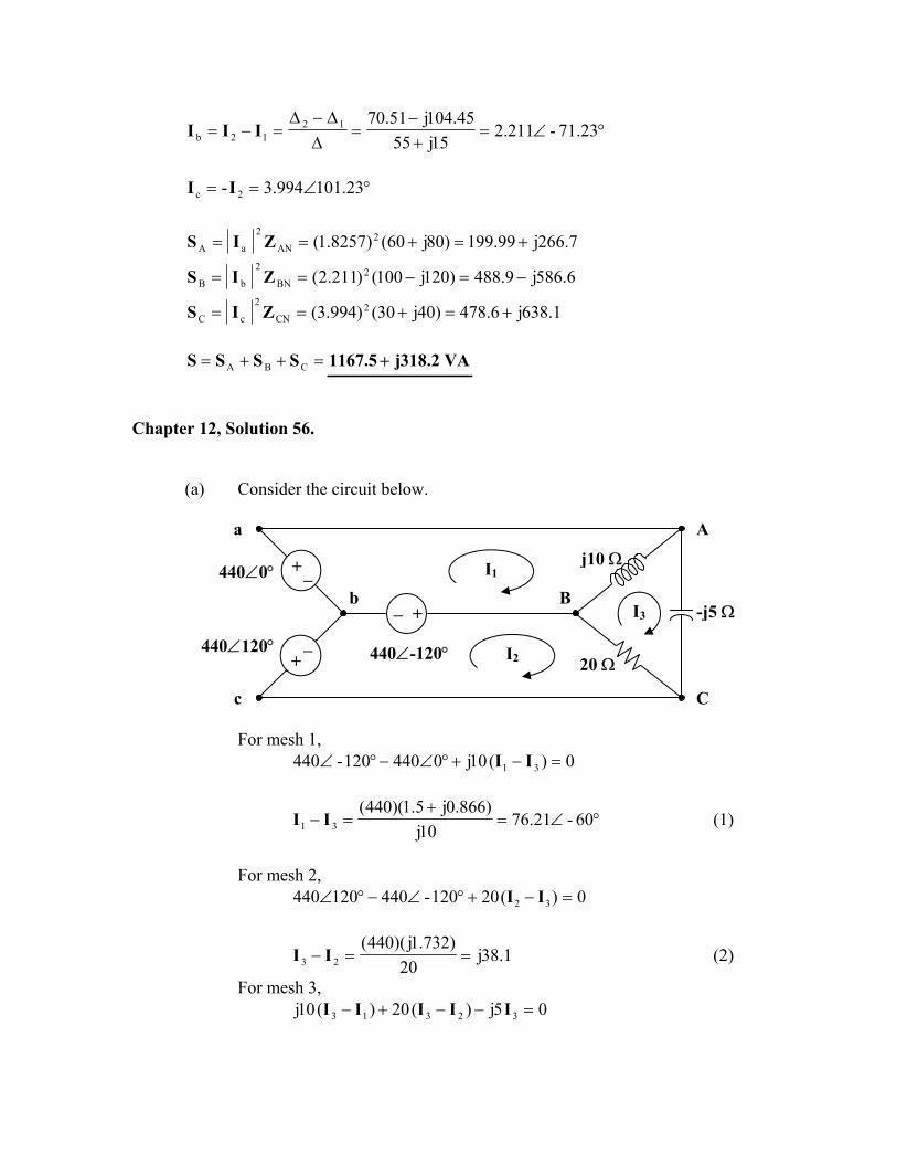
(a) Consider the circuit below.
For mesh 1,
0)(10j0440120-440 31 =−+°∠−°∠ II
°∠=+
=− 60-21.7610j
)866.0j5.1)(440(31 II (1)
For mesh 2,
0)(20120-440120440 32 =−+°∠−°∠ II
1.38j20
)732.1j)(440(23 ==− II (2)
For mesh 3, 05j)(20)(10j 32313 =−−+− IIIII
I2
I1
b −
+
+−
440∠-120°440∠120°
440∠0°
− +
BI3
20 Ω
j10 Ω
a A
-j5 Ω
C c

Substituting (1) and (2) into the equation for mesh 3 gives,
°∠=+
= 6042.152j5
j0.866)-1.5)(440(3I (3)
From (1),
°∠=+=°∠+= 3013266j315.11460-21.7631 II From (2),
°∠=+=−= 50.9493.1209.93j21.761.38j32 II
== 1a II A30132 °∠
=+=−= j27.9-38.10512b III A143.823.47 °∠
== 2c -II A230.99.120 °∠
(b) kVA08.58j)10j(2
31AB =−= IIS
kVA04.29)20(2
32BC =−= IIS
kVA-j116.16-j5)((152.42)-j5)( 22
3CA === IS
kVA08.58j04.29CABCAB −=++= SSSS Real power absorbed = 29 kW04.
(c) Total complex supplied by the source is =S kVA08.58j04.29 −

Chapter 12, Solution 57.
We apply mesh analysis to the circuit shown below. Ia
+ Va Ω+ 50j80 - I1 - - Ω+ 3020 j
Vc Vb + + Ib
I2 Ic
Ω− 4060 j
263.95165)3020()80100( 21 jVVIjIj ba +=−=+−+ (1) 53.190)1080()3020( 21 jVVIjIj cb −=−=−++− (2)
Solving (1) and (2) gives 722.19088.0,6084.08616.1 21 jIjI −=−= .
55.1304656.11136.1528.0,A 1.189585.1 121 bo
a jIIIII −∠=−−=−=−∠==
A 8.117947.12o
c II ∠=−= Chapter 12, Solution 58. The schematic is shown below. IPRINT is inserted in the neutral line to measure thecurrent through the line. In the AC Sweep box, we select Total Ptss = 1, Start Freq0.1592, and End Freq. = 0.1592. After simulation, the output file includes
FREQ IM(V_PRINT4) IP(V_PRINT4) 1.592 E–01 1.078 E+01 –8.997 E+01
A o
. =
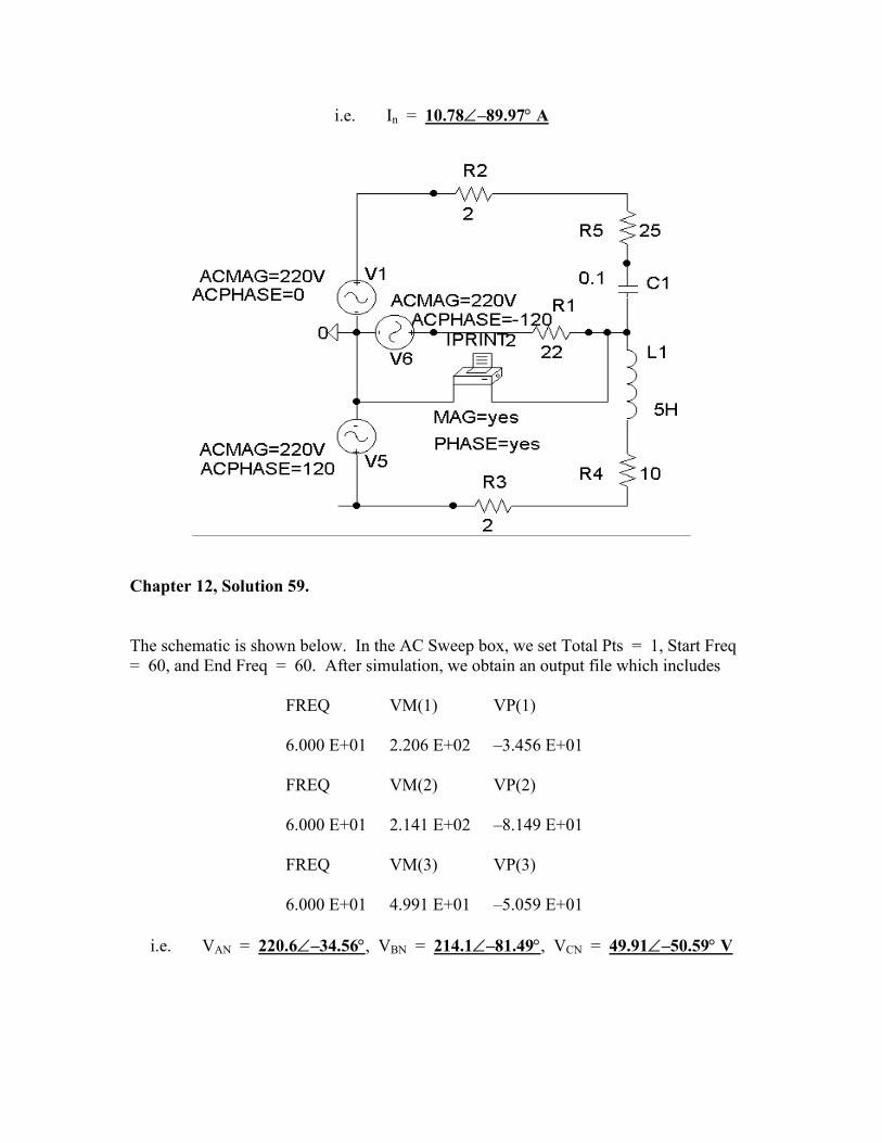
i.e. In = 10.78∠–89.97° A
Chapter 12, Solution 59. The schematic is shown below. In the AC Sweep box, we set Total Pts = 1, Start Freq = 60, and End Freq = 60. After simulation, we obtain an output file which includes
FREQ VM(1) VP(1) 6.000 E+01 2.206 E+02 –3.456 E+01 FREQ VM(2) VP(2) 6.000 E+01 2.141 E+02 –8.149 E+01 FREQ VM(3) VP(3) 6.000 E+01 4.991 E+01 –5.059 E+01
i.e. VAN = 220.6∠–34.56°, VBN = 214.1∠–81.49°, VCN = 49.91∠–50.59° V

hapter 12, Solution 60.
he schematic is shown below. IPRINT is inserted to give Io. We select Total Pts = 1,
FREQ IM(V_PRINT4) IP(V_PRINT4)
.592 E–01 1.421 E+00 –1.355 E+02
om which, Io = 1.421∠–135.5° A
C TStart Freq = 0.1592, and End Freq = 0.1592 in the AC Sweep box. Upon simulation, the output file includes
1
fr

Chapter 12, Solution 61. The schematic is shown below. Pseudocomponents IPRINT and PRINT are inserted to measure IaA and VBN. In the AC Sweep box, we set Total Pts = 1, Start Freq = 0.1592, and End Freq = 0.1592. Once the circuit is simulated, we get an output file which includes
FREQ VM(2) VP(2) 1.592 E–01 2.308 E+02 –1.334 E+02 FREQ IM(V_PRINT2) IP(V_PRINT2) 1.592 E–01 1.115 E+01 3.699 E+01
from which IaA = 11.15∠37° A, VBN = 230.8∠–133.4° V

Chapter 12, Solution 62. Because of the delta-connected source involved, we follow Example 12.12. In the AC Sweep box, we type Total Pts = 1, Start Freq = 60, and End Freq = 60. After simulation, the output file includes
FREQ IM(V_PRINT2) IP(V_PRINT2) 6.000 E+01 5.960 E+00 –9.141 E+01 FREQ IM(V_PRINT1) IP(V_PRINT1) 6.000 E+01 7.333 E+07 1.200 E+02
From which Iab = 7.333x10⁷∠120° A, IbB = 5.96∠–91.41° A

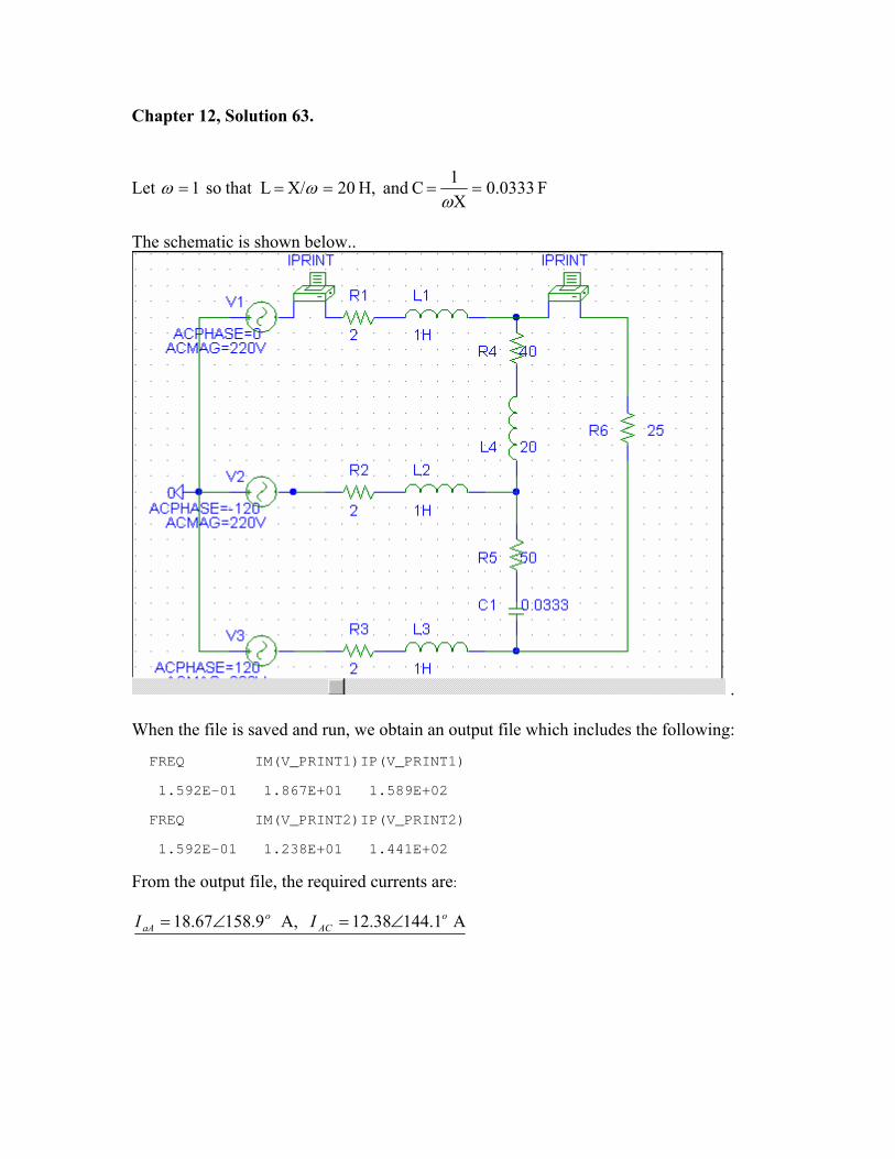
Chapter 12, Solution 63.
Let F 0333.0X1 C and H, 20X/ L that so 1 =====ω
ωω
The schematic is shown below..
.
When the file is saved and run, we obtain an output file which includes the following: FREQ IM(V_PRINT1)IP(V_PRINT1) 1.592E-01 1.867E+01 1.589E+02 FREQ IM(V_PRINT2)IP(V_PRINT2) 1.592E-01 1.238E+01 1.441E+02 From the output file, the required currents are:
A 1.14438.12 A, 9.15867.18 oAC
oaA II ∠=∠=
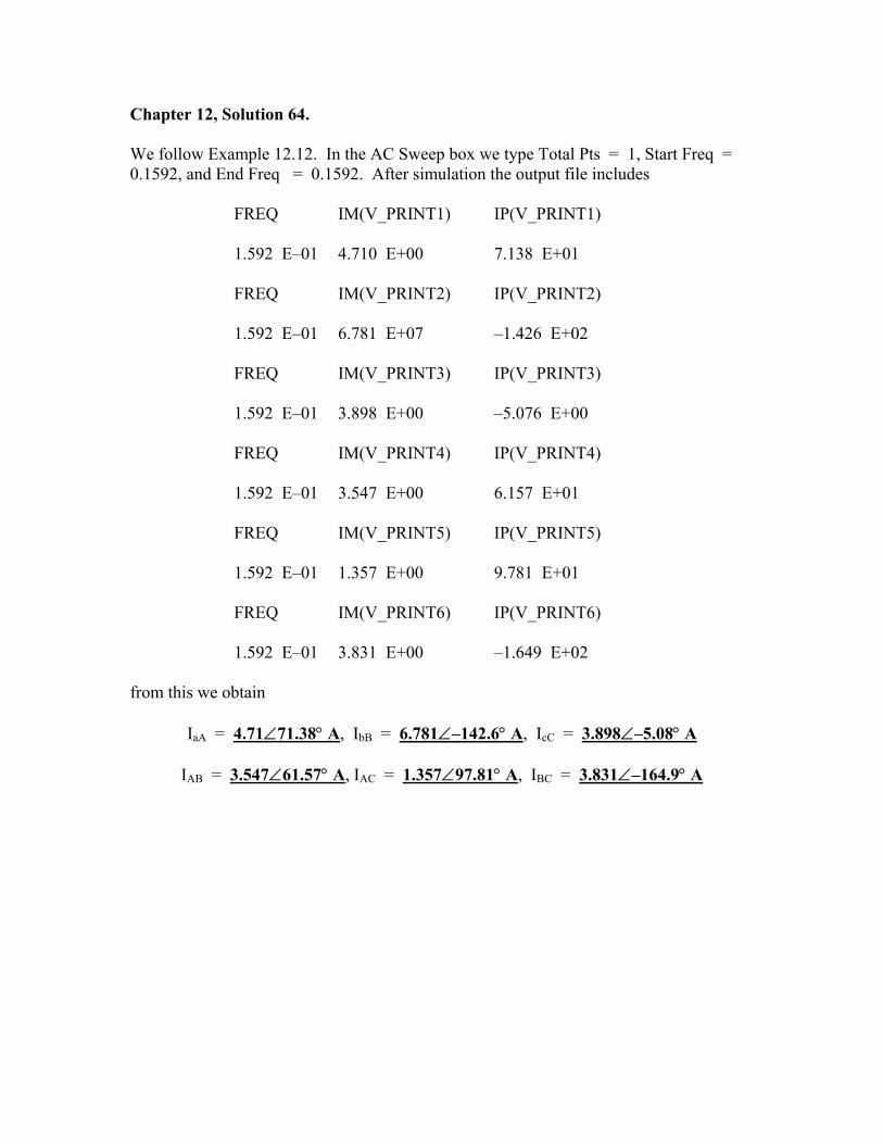
Chapter 12, Solution 64. We follow Example 12.12. In the AC Sweep box we type Total Pts = 1, Start Freq = 0.1592, and End Freq = 0.1592. After simulation the output file includes
FREQ IM(V_PRINT1) IP(V_PRINT1) 1.592 E–01 4.710 E+00 7.138 E+01 FREQ IM(V_PRINT2) IP(V_PRINT2) 1.592 E–01 6.781 E+07 –1.426 E+02 FREQ IM(V_PRINT3) IP(V_PRINT3) 1.592 E–01 3.898 E+00 –5.076 E+00 FREQ IM(V_PRINT4) IP(V_PRINT4) 1.592 E–01 3.547 E+00 6.157 E+01 FREQ IM(V_PRINT5) IP(V_PRINT5) 1.592 E–01 1.357 E+00 9.781 E+01 FREQ IM(V_PRINT6) IP(V_PRINT6) 1.592 E–01 3.831 E+00 –1.649 E+02
from this we obtain
IaA = 4.71∠71.38° A, IbB = 6.781∠–142.6° A, IcC = 3.898∠–5.08° A
IAB = 3.547∠61.57° A, IAC = 1.357∠97.81° A, IBC = 3.831∠–164.9° A
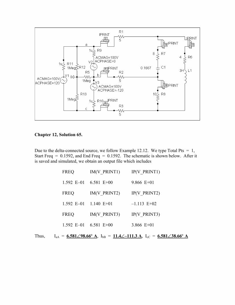
Chapter 12, Solution 65. Due to the delta-connected source, we follow Example 12.12. We type Total Pts = 1, Start Freq = 0.1592, and End Freq = 0.1592. The schematic is shown below. After it is saved and simulated, we obtain an output file which includes
FREQ IM(V_PRINT1) IP(V_PRINT1) 1.592 E–01 6.581 E+00 9.866 E+01 FREQ IM(V_PRINT2) IP(V_PRINT2) 1.592 E–01 1.140 E+01 –1.113 E+02 FREQ IM(V_PRINT3) IP(V_PRINT3) 1.592 E–01 6.581 E+00 3.866 E+01
Thus, IaA = 6.581∠98.66° A, IbB = 11.4∠–111.3 A, IcC = 6.581∠38.66° A

Chapter 12, Solution 66. Chapter 12, Solution 66.
(a) ===3
2083
VV L
p V120 (a)
===3
2083
VV L
p V120
(b) Because the load is unbalanced, we have an unbalanced three-phase system. Assuming an abc sequence,
(b) Because the load is unbalanced, we have an unbalanced three-phase system. Assuming an abc sequence,
A05.248
01201 °∠=
°∠=I
A120-340
120-1202 °∠=
°∠=I
A120260
1201203 °∠=
°∠=I
A05.248
01201 °∠=
°∠=I
A120-340
120-1202 °∠=
°∠=I
A120260
1201203 °∠=
°∠=I
++
−+=++=
23
j5.0-)2(23
j0.5-)3(5.2- 321N IIII
++
−+=++=
23
j5.0-)2(23
j0.5-)3(5.2- 321N IIII

A90866.0866.0j23
jN °∠===I
Hence, =1I A5.2 , =2I A3 , =3I A2 , =NI A866.0
(c) === )48()5.2(RIP 2
1211 W300
=== )40()3(RIP 22
222 W360
=== )60()2(RIP 23
233 W240
(d) =++= 321T PPPP W900
Chapter 12, Solution 67.
(a) The power to the motor is kW221)85.0)(260(cosSPT ==θ=
The motor power per phase is
kW67.73P31
P Tp ==
Hence, the wattmeter readings are as follows:
=+= 2467.73Wa kW67.97 =+= 1567.73Wb kW67.88 =+= 967.73Wc kW67.83
(b) The motor load is balanced so that 0IN = .
For the lighting loads,
A200120
000,24Ia ==
A125120
000,15Ib ==
A75120000,9
Ic ==
If we let

A02000Iaa °∠=°∠=I A120-125b °∠=I
A12075c °∠=I Then,
cbaN- IIII ++=
++
−+=
23
j0.5-)75(23
j5.0-)125(200- NI
A602.86100- N −=I
=NI A3.132 Chapter 12, Solution 68.
(a) === )4.8)(330(3IV3S LL VA4801
(b) SP
cospfcosSP =θ=→θ=
==24.4801
4500pf 9372.0
(c) For a wye-connected load,
== Lp II A4.8
(d) ===3
3303
VV L
p V53.190
Chapter 12, Solution 69.
MVA 8.0SMVA, 323.15.1)661.075.0(2SMVA, 72.096.0)6.08.0(2.1 321 =−=−=+=+= jjjS
9833.03153.326.3MVA, 603.026.3321 ===−=++=
SPpfjSSSS
MVA 1379.0)99.0tan(cos)9833.0[tan(cos26.3)tan(tan 11 =−=−= −−
newoldc PQ
mF 28106.6602
101379.031
62
6
==xxx
xxC
π

Chapter 12, Solution 70.
8004001200PPP 21T =−=+=
1600-1200400-PPQ 12T =−=−=
°=θ→===θ -63.43-28001600-
PQ
tanT
T
=θ= cospf (leading)4472.0
406
240IV
ZL
Lp ===
=pZ Ω°∠ 63.43-40
Chapter 12, Solution 71.
(a) If , °∠= 0208abV °∠= 120-208bcV , °∠= 120208caV ,
°∠=°∠
== 04.1020
0208
Ab
abAB Z
VI
°∠=°∠°∠
== 75-708.1445-210
120-208
BC
bcBC Z
VI
°∠=°∠°∠
== 97.381622.6213
120208
CA
caCA Z
VI
°∠−°∠=−= 97.381604.10CAABaA III
867.15j055.24.10aA −+=I °∠= 51.87-171.20aAI
°∠−°∠=−= 75-708.1497.8316BCCAcC III
°∠= 101.0364.30cCI
)cos(PaAab IVaAab1 θ−θ= IV

=°+°= )87.510cos()171.20)(208(P1 W2590
)cos(PcCcb IVcCcb2 θ−θ= IV
But °∠== 60208- bccb VV
=°−°= )03.10160cos()64.30)(208(P2 W4808
(b) W17.7398PPP 21T =+=
VAR25.3840)PP(3Q 12T =−= =+= TTT jQPS VA25.3840j17.7398 +
== TTS S V8335 A Chapter 12, Solution 72. From Problem 12.11,
V130220AB °∠=V and A18030aA °∠=I
=°−°= )180130cos()30)(220(P1 W4242
°∠== 190220- BCCB VV °∠= 60-30cCI
=°+°= )60190cos()30)(220(P2 W2257-
Chapter 12, Solution 73. Consider the circuit as shown below.
I1
I2
Z
Z
240∠-120° V − +
Ia
Ib
+ − 240∠-60° V
Z
Ic

°∠=+= 71.5762.3130j10Z
°∠=°∠
°∠= 131.57-59.7
71.5762.3160-240
aI
°∠=°∠°∠
= 191.57-59.771.5762.31120-240
bI
0120-24060-240c =°∠−°∠+ZI
°∠=°∠
= 108.4359.771.5731.62
240-cI
°∠=−= 101.57-146.13ca1 III °∠=+= 138.43146.13cb2 III
[ ] [ ] =°∠°∠== ).57101146.13)(60-240(ReReP *
111 IV W2360
[ ] [ ] =°∠°∠== )138.43-146.13)(120-240(ReReP *222 IV W8.632-
Chapter 12, Solution 74. Consider the circuit shown below.
Z = 60 − j30 Ω
For mesh 1,
− + 208∠-60° V I2
I1+ − 208∠0° V
Z
Z
212208 IZIZ −= For mesh 2,
21 2-60-208- IZIZ +=°∠

In matrix form,
=
°∠ 2
1
2--2
60-208-208
II
ZZZZ
23Z=∆ , Z)866.0j5.1)(208(1 +=∆ , Z)732.1j)(208(2 =∆
°∠=−+
=∆∆
= 56.56789.1)30j60)(3(
)866.0j5.1)(208(11I
°∠=−
=∆∆
= 116.5679.1)30j60)(3()732.1j)(208(2
2I
[ ] [ ] =°∠== )56.56-789.1)(208(ReReP *
111 IV W98.208
[ ] [ ] =°∠°∠== )63.4479.1))(60-208(Re)-(ReP *222 IV W65.371
Chapter 12, Solution 75.
(a) ===60012
RV
I mA20
(b) ===600120
RV
I mA200
Chapter 12, Solution 76. If both appliances have the same power rating, P,
sVP
I =
For the 120-V appliance, 120
PI1 = .
For the 240-V appliance, 240P
I2 = .
Power loss =
=appliance -V240 for the
240RP
appliance -V120 for the120
RP
R2
2
2
2
2I
Since 22 2401
1201
> , the losses in the 120-V appliance are higher.

Chapter 12, Solution 77. , lineloadTg PPPP −−= 85.0pf =
But 3060pf3600cos3600PT =×=θ=
=−−= )80)(3(25003060Pg W320 Chapter 12, Solution 78.
°=θ→==θ 79.3185.06051
cos 11
kVAR61.31)5268.0)(60(sinSQ 111 ==θ=
kW51PP 12 ==
°=θ→=θ 19.1895.0cos 22
kVA68.53cos
PS
2
22 =
θ=
kVAR759.16sinSQ 222 =θ=
kVAR851.14759.1661.3QQQ 21c =−=−=
For each load,
kVAR95.43
QQ c
1c ==
=π
=ω
= 221c
)440)(60)(2(4950
VQ
C F82.67 µ
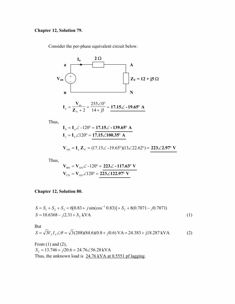
Chapter 12, Solution 79. Consider the per-phase equivalent circuit below.
Ia
n
a
Van + −
2 ΩA
ZY = 12 + j5 Ω
N
=+
°∠=
+=
5j140255
2Y
ana Z
VI A19.65-15.17 °∠
Thus,
=°∠= 120-ab II A139.65-15.17 °∠ =°∠= 120ac II A100.3515.17 °∠
=°∠°∠== )22.6213)(19.65-15.17(YaAN ZIV V2.97223 °∠
Thus,
=°∠= 120-ANBN VV V117.63-223 °∠ =°∠= 120ANCN VV V122.97223 °∠
Chapter 12, Solution 80.
)7071.07071.0(8)]83.0sin(cos83.0[6 21
321 jSjSSSS −+++=++= − kVA 31.26368.10 2SjS +−= (1)
But
kVA j18.28724.383 VA )6.08.0)(6.84)(208(33 +=+=∠= jIVS LL θ (2) From (1) and (2),
kVA 28.5676.246.20746.132 ∠=+= jS Thus, the unknown load is 24.76 kVA at 0.5551 pf lagging.


Chapter 12, Solution 82.
p
p
ZVjjS *
2
21 3SkVA, 240320)6.08.0(400 =+=+=
For the delta-connected load, V pL V=
kVA 93.8427.1053810)2400(3
2
2 jj
xS +=−
=
MVA 0829.13737.121 jSSS +=+=
Let I = I1 + I2 be the total line current. For I1,
3,3 1
*1
Lpp
VVIVS ==
735.5798.76,)2400(310)240320(
3 1
31
1* jIxj
VSI
L
−=+
==
For I2, convert the load to wye.
76.2891.273303810
24003032 jj
II oop −=−∠
+=−∠=
5.34735021 jIII −=+=
kV 372.5||kV 405.1185.5)63(2400 =→+=++=+= slineLs VjjIVVV
Chapter 12, Solution 83.
kVA 80SkVA, 135.60135.60)707.0707.0(95.0746120 21 =+=+= jjxxS
kVA 135.60135.14021 jSSS +=+=
A 42.1834803
1049.1523
||3||But 3
===→=xx
VSIIVSL
LLL

Chapter 12, Solution 84. We first find the magnitude of the various currents.
For the motor,
A248.53440
4000V3
SI
LL ===
For the capacitor,
A091.4440
1800VQ
IL
cC ===
For the lighting,
V2543
440Vp ==
A15.3254800
VP
Ip
LiLi ===
Consider the figure below.
Ia I1a
-jXC
R In
ILi
I3
I2
Ic
+
Vab
−Ib
IC
b
c
n
If , °∠= 0VpanV °∠= 30V3 pabV °∠= 120VpcnV
°∠== 120091.4X-j C
abC
VI
)30(091.4ab1 °+θ∠==
∆ZV
I
where θ °== 95.43)72.0(cos-1
°∠= 73.95249.51I
°∠= 46.05-249.52I
°∠= 193.95249.53I
°∠== 12015.3R
cnLi
VI
Thus,
°∠+°∠=+= 120091.473.95249.5C1a III =aI A93.96608.8 °∠
°∠−°∠=−= 120091.446.05-249.5C2b III
=bI A52.16-271.9 °∠
°∠+°∠=+= 12015.3193.95249.5Li3c III =cI A167.6827.6 °∠
== Lin -II A60-15.3 °∠
Chapter 12, Solution 85. Let Z RY =
V56.1383
2403
VV L
p ===
RV
kW92
27IVP
2p
pp ====
Ω=== 133.29000
)56.138(P
VR
22p
Thus, =YZ Ω133.2
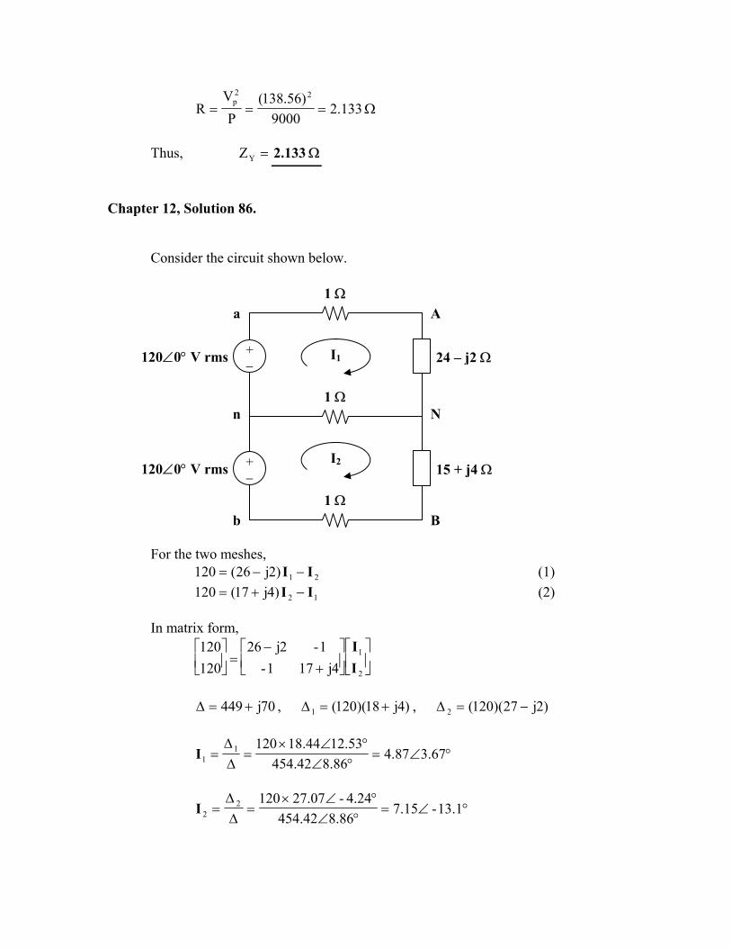
Chapter 12, Solution 86. Consider the circuit shown below.
1 Ω
B
N
A
b
n
I1
I2+ − 120∠0° V rms 15 + j4 Ω
24 – j2 Ω
1 Ω
a
+ − 120∠0° V rms
1 Ω
For the two meshes,
21)2j26(120 II −−= (1)
12)4j17(120 II −+= (2)
In matrix form,
+
−=
2
1
4j171-1-2j26
120120
II
70j449 +=∆ , )4j18)(120(1 +=∆ , )2j27)(120(2 −=∆
°∠=°∠°∠×
=∆∆
= 3.6787.48.8642.454
12.5344.1812011I
°∠=°∠
°∠×=
∆∆
= 13.1-15.78.8642.454
4.24-07.2712022I
== 1aA II A3.6787.4 °∠ == 2bB -II A166.915.7 °∠
∆∆−∆
=−= 1212nN III
=+−
=70j449
)6j9)(120(nNI A42.55-856.2 °∠
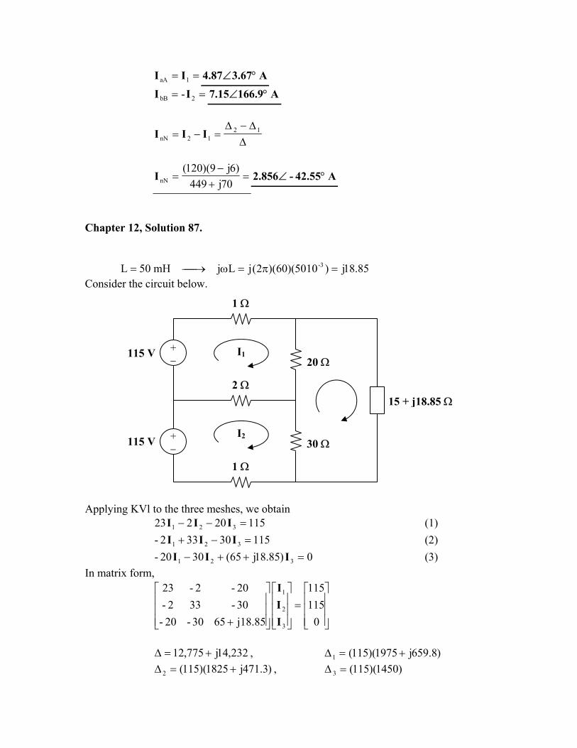
Chapter 12, Solution 87. 85.18j)5010)(60)(2(jLjmH50L 3- =π=ω→=Consider the circuit below.
1 Ω
30 Ω
20 ΩI1
I2+ −
2 Ω
+ −
1 Ω
115 V
15 + j18.85 Ω
115 V
Applying KVl to the three meshes, we obtain
11520223 321 =−− III (1) 11530332- 321 =−+ III (2)
0)85.18j65(3020- 321 =++− III (3) In matrix form,
=
+ 0115115
j18.856530-20-30-332-20-2-23
3
2
1
III
232,14j775,12 +=∆ , )8.659j1975)(115(1 +=∆
)3.471j1825)(115(2 +=∆ , )1450)(115(3 =∆

°∠=°∠°∠×
=∆∆
= 29.62-52.1248.0919214
47.18208211511I
°∠=°∠
°∠×=
∆∆
= 33.61-33.1148.0919124
14.489.188411522I
=+
−=
∆∆−∆
=−=75.231,14j775,12
)5.188j-150)(115(1212n III A176.6-448.1 °∠
=°∠== )29.6252.12)(115(IVS *
111 VA6.711j1252 +
=°∠== )33.6133.1)(115(*222 IVS V2.721j1085 A+