chapter 7 flexible and conformable antennas for body
TRANSCRIPT

CHAPTER 7
Flexible and Conformable Antennas for Body-Centric Radiofrequency Identification
R. Lodato, S. Manzari, C. Occhiuzzi & G. MarroccoPervasive Electromagnetics Lab, University of Rome “Tor Vergata”,Italy.
Abstract
The fast growth of radiofrequency identification (RFID) research is currently exploring new applications for body-centric systems where flexible, miniatur-ized and conformal antennas are required for placement over the human body and implantation inside limbs and internal organs. When compared with conventional antennas for body-centric purpose, the design of RFID tags involve additional challenges related to the absence of local power source and, in some cases, to the close interaction with the interrogating unit.
This chapter reviews the state of the art in the design and experimentation of flexible and conformable antennas for body-centric RFID applications with great attention to the definition of the performance parameters, the achievable read range, and finally, the technology solutions. For the most challenging family of implantable antennas, two cases study are given concerning design and experi-mentation of tags for orthopaedic limb prosthesis and for vascular implants.
Keywords: RFID, flexible tag, conformal tag, body-centric system.
1 Introduction
In the near future, a strategic role in welfare and particularly in healthcare will be played by body-centric networks wherein wearable and implantable sensors pro-vide real-time information on the health conditions and interactions of a person, and in more futuristic applications, data about the ageing and safety of prosthesis and artificial organs. Progress in low-power microchip transponders, reducing the issues of power requirement, is currently pushing the radiofrequency identification (RFID) as a key technology in the development of low-cost miniaturized battery-less radio-sensors by exploiting the assessed communication standards and its potential pervasivity.
www.witpress.com, ISSN 1755-8336 (on-line) WIT Transactions on State of the Art in Science and Engineering, Vol 82, © 2014 WIT Press
doi:10.2495/978-1-84564-986-9/007
124 InnovatIon In Wearable and FlexIble antennas
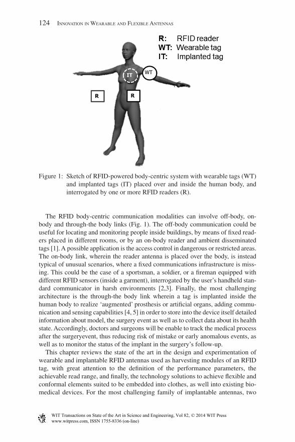
The RFID body-centric communication modalities can involve off-body, on-body and through-the body links (Fig. 1). The off-body communication could be useful for locating and monitoring people inside buildings, by means of fixed read-ers placed in different rooms, or by an on-body reader and ambient disseminated tags [1]. A possible application is the access control in dangerous or restricted areas. The on-body link, wherein the reader antenna is placed over the body, is instead typical of unusual scenarios, where a fixed communications infrastructure is miss-ing. This could be the case of a sportsman, a soldier, or a fireman equipped with different RFID sensors (inside a garment), interrogated by the user’s handheld stan-dard communicator in harsh environments [2,3]. Finally, the most challenging architecture is the through-the body link wherein a tag is implanted inside the human body to realize ‘augmented’ prosthesis or artificial organs, adding commu-nication and sensing capabilities [4, 5] in order to store into the device itself detailed information about model, the surgery event as well as to collect data about its health state. Accordingly, doctors and surgeons will be enable to track the medical process after the surgeryevent, thus reducing risk of mistake or early anomalous events, as well as to monitor the status of the implant in the surgery’s follow-up.
This chapter reviews the state of the art in the design and experimentation of wearable and implantable RFID antennas used as harvesting modules of an RFID tag, with great attention to the definition of the performance parameters, the achievable read range, and finally, the technology solutions to achieve flexible and conformal elements suited to be embedded into clothes, as well into existing bio-medical devices. For the most challenging family of implantable antennas, two
Figure 1: Sketch of RFID-powered body-centric system with wearable tags (WT) and implanted tags (IT) placed over and inside the human body, and interrogated by one or more RFID readers (R).
www.witpress.com, ISSN 1755-8336 (on-line) WIT Transactions on State of the Art in Science and Engineering, Vol 82, © 2014 WIT Press

FlexIble and conForMable antennas For body-centrIc radIoFrequency IdentIFIcatIon 125
case studies are given concerning design and experimentation of tags for orthopae-dic prosthesis and the conversion of a vascular stent into a multi-purpose confor-mal RFID antenna with sensing capability.
2 RFID Technology
A RFID system comprises two elements, a remote transponder that includes an antenna connected to a microchip and a radio scanner device called the reader. A first classification of RFID system can be done in terms of operating frequen-cies: LF (low frequency, 120–145 KHz), HF (high frequency, 13.56 MHz), UHF (ultra high frequency, 866–956 MHz). Battery-less tags are particularly attrac-tive due to their characteristic of low-cost, theoretically infinite life, no need of maintenance, lightweight, and a high possibility of integration in implant-able and wearable applications. The passive tag harvests the energy needed for activation from the reader and sends back data stored in the IC, modulating the back-scattered signal.
UHF devices, although influenced by high dielectric targets, may in principle promise larger activation ranges. Together with the microchip sensitivity, the design of the tag antenna plays a key role in the RFID system performance, to achieve reasonable reading ranges while maintaining restrained dimensions.
The power budget of UHF-RFID radio channel, i.e. the power transmitted by the reader and collected by the tag (direct link), and the power backscattered by the tag towards the reader (backward link), are commonly characterized in far field by means the Friis formula and the radar equation [6].
Pd
P G GR T R P→ =
⋅λπ
τ η0
2
4 in Tag (1)
Pd
P GR T R T P← =
1
4 40
2
2
2
πλπ
ηin rcs (2)
where G GTag Tag= ⋅ τ is the realized gain of the tag, i.e. the radiation gain GTag of the tag antenna reduced by the power transfer coefficient t between tag antenna and the microchip, Pin is the power emitted by the reader, GR is the reader antenna gain, hP is the polarization factor between the reader and the tag, d is the distance between reader and tag antennas, l0 is the free-space wavelength, and is the Radar Cross Section of the tag.
The power transmission coefficient can be expressed in terms of tag antenna and tag IC impedance ZA = RA + iXA and Zchip = Rchip + iXchip by
τ =+
<4
12
R R
Z Z
A
A
chip
chip
(3)
www.witpress.com, ISSN 1755-8336 (on-line) WIT Transactions on State of the Art in Science and Engineering, Vol 82, © 2014 WIT Press
126 InnovatIon In Wearable and FlexIble antennas
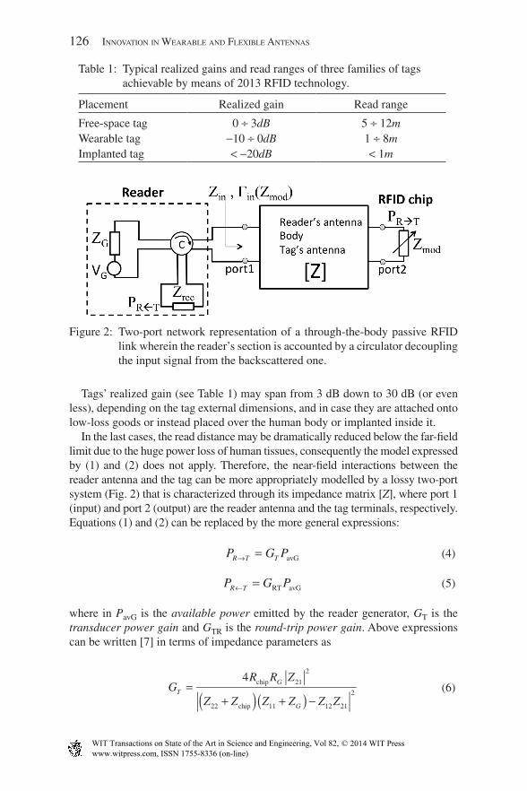
Tags’ realized gain (see Table 1) may span from 3 dB down to 30 dB (or even less), depending on the tag external dimensions, and in case they are attached onto low-loss goods or instead placed over the human body or implanted inside it.
In the last cases, the read distance may be dramatically reduced below the far-field limit due to the huge power loss of human tissues, consequently the model expressed by (1) and (2) does not apply. Therefore, the near-field interactions between the reader antenna and the tag can be more appropriately modelled by a lossy two-port system (Fig. 2) that is characterized through its impedance matrix [Z], where port 1 (input) and port 2 (output) are the reader antenna and the tag terminals, respectively. Equations (1) and (2) can be replaced by the more general expressions:
P G PR T T→ = avG (4)
P G PR T← = RT avG (5)
where in PavG is the available power emitted by the reader generator, GT is the transducer power gain and GTR is the round-trip power gain. Above expressions can be written [7] in terms of impedance parameters as
GR R Z
Z Z Z Z Z ZT
G
G
=+( ) +( ) −
4 21
2
22 11 12 21
2
chip
chip
(6)
Table 1: Typical realized gains and read ranges of three families of tags achievable by means of 2013 RFID technology.
Placement Realized gain Read range
Free-space tag 0 ÷ 3dB 5 ÷ 12mWearable tag ‑10 ÷ 0dB 1 ÷ 8mImplanted tag < ‑20dB < 1m
Figure 2: Two-port network representation of a through-the-body passive RFID link wherein the reader’s section is accounted by a circulator decoupling the input signal from the backscattered one.
www.witpress.com, ISSN 1755-8336 (on-line) WIT Transactions on State of the Art in Science and Engineering, Vol 82, © 2014 WIT Press

FlexIble and conForMable antennas For body-centrIc radIoFrequency IdentIFIcatIon 127
GZ Z
Z Z Z Z Z Z Z ZG
G
RTrec chip
=+ +( ) +( ) −
122
11
2
11 22 12 21
2
1 (7)
where Zchip is the microchip impedance in harvesting mode and Rchip its real part, RG is the resistance of reader transmitter (supposed real) and Zrec is the impedance of the reader receiver.
The feasibility of an RFID link including wearable and even more implantable antennas is strongly dependent on the current technology, e.g. on the microchip and reader receiver sensitivities; this can be translated in the satisfaction of two conditions involving the power budget of both the direct and forward link. The Direct Link Margin, represents a power balance between the power transmitted from the reader towards the tag, and the power needed to activate the IC, whereas the Backward Link Margin , quantifies the capability of the reader receiver to detect the tag response.
M P pR TDL chip= − >→ 0 (8)
M P pR TBL rdr= − >← 0 (9)
The RFID channel will be hence fully active when both conditions (8) and (9) are satisfied.
3 Passive Wearable UHF Tags
Recent progress in the design of UHF RFID tag antennas suited to be put in direct contact or in close proximity with the body motivates the idea of passive body-centric systems, fully transparent to the users and able to monitor people’s secu-rity, healthcare, and, in a more innovative vision, even social behaviour. While active body-centric links have been extensively considered for long time [8], the feasibility of passive systems for on-body applications is still under investigation due to the high-power attenuation caused by the human tissues and, until recently, the poor sensitivity of the ICs.
In the last few years, however, the availability of COTS (Commercial Off The Shelves) low-power RFID microchips has changed the state of possibilities, allow-ing the successful development and experimental characterization of many proto-types of passive on-body tags fully compliant with a true remote monitoring.
3.1 Characteristics of wearable tags and state of the art
Most of the RFID tags proposed in literature or commercially available for different applications are designed to work in conditions of free space, and when applied to objects with high permittivity, such as the human body, they suffer from a strong distortion of the radiation pattern, loss of efficiency, and consequently a drastic
www.witpress.com, ISSN 1755-8336 (on-line) WIT Transactions on State of the Art in Science and Engineering, Vol 82, © 2014 WIT Press

128 InnovatIon In Wearable and FlexIble antennas
reduction of the maximum reading distance. The high permittivity of the human tissues in fact leads to an increase in the electrical length of the antenna, shifting the resonance to lower frequencies. This effect can be roughly estimated by
lL
=λ
ε0
eff (10)
where L is the dominant size of the wearable antenna, l0 is the wavelength in free space, and eeff > 1 is the effective permittivity, which takes into account that the electric field propagates through the air and the human tissues.
The high conductivity of the body, instead, induces a great dissipation of elec-tromagnetic power, highly degrading the radiation pattern of the antenna. There-fore, the presence of the human body needs to be carefully taken into account by electromagnetic simulations and modelling [9,11]. The main goal of passive wearable antennas is to achieve immunity to the negative effects induced by the human body and maximum insensibility to the placement in different body regions, while keeping flexible structures with external dimensions as small as possible.
The performance indicator of an on-body tag for indoor reliable monitoring is the maximum reading range dmax between reader and tag. dmax is proportionally dependent on the antenna radiation characteristics and can be realistically approx-imated by the Friis free space equation.
dG P
max
Tag
chip
EIRP
P=
⋅ ⋅λπ
η0
4
ˆ (11)
where EIRP = ⋅G PR in is the equivalent isotropic radiated power emitted by the
reader and fixed to or , depending on the different countries regulations. An exam-ple of measurement set-up for on-body tags characterization is shown in Fig. 3.
The design efforts of last years were aimed at obtaining light-weight thin struc-tures, possibly flexible and suitable to be integrated into clothes. In the recent years, several studies [12,13] have been published regarding passive UHF wear-able antenna designs, whose geometrical characteristics can be summarized in three categories:
1. Patch-kind configurations with a ground plane, which makes the antenna impedance immune to the particular half below.
2. Multilayered planar antennas.3. Simple single-layer antennas such as dipoles or slot that use the body itself as a
reflector plane, with the shrewdness of sufficiently spacing the tags from the body.
Many examples of wearable antennas are reviewed next with respect to the exter-nal size and to the radiation performances expressed in terms of the realized gain.
www.witpress.com, ISSN 1755-8336 (on-line) WIT Transactions on State of the Art in Science and Engineering, Vol 82, © 2014 WIT Press

FlexIble and conForMable antennas For body-centrIc radIoFrequency IdentIFIcatIon 129
Marrocco [9] performed an extensive parametric study on a single-layer slotted structure simulated on a multi-layered elliptical model resembling the characteris-tic of human tissue. It was demonstrated how, by parametric variations of the geo-metric dimensions, a range of antennas from dipole to loop can be matched to several chip impedances. To avoid the effect of short circuit induced by the body, the metallization is insulated by a layer of silicone, having high permittivity ( . )ε’ = 11 9 .
Two patch layouts (size 165 mm × 74 mm × 4.8 mm and 155 mm × 74 mm × 4.8 mm) on dielectric flexible foam for wearable RFID antennas are presented by Švanda and Polívka in [14]. The ground plane has an area twice the size of the patch (Fig. 4a) achieving a maximum realized gain of almost 5 dB. Other two wearable tags [15,16] proposed by previous authors are three-layer and two-etrical character-istics layers structures, consisting in the first case of dipoles superimposed to an array of patches, and a ground plane below and in the second case of a simple patch. External sizes (95 mm × 65 mm × 1 mm and 100 mm × 60 mm × 0.76 mm) are smaller than those of previous examples; however, the maximum realized gain decreases down to about 1 dB. Still Švanda and Polívka [17] proposed a three-layer tag with a double loop over an array of patches and a ground plane (Fig. 4b). The resulting layout is a slot antenna excited by the loop. The tag was measured on an agar phantom, and the resulting realized gain is around 0.5 dB.
Figure 3: Measurement set-up for RFID wearable tags. The tag placed on body is interrogated by means of a circular or linear polarized antenna con-nected to the reader. Ground reflections may be minimized by using absorbing panels.
www.witpress.com, ISSN 1755-8336 (on-line) WIT Transactions on State of the Art in Science and Engineering, Vol 82, © 2014 WIT Press

130 InnovatIon In Wearable and FlexIble antennas
Rajagopalan and Rahmat-Samii [18] describe a dual-patch forming a central radiating slot antenna with a ground plane. The structure consists of a metal strip doubly folded around a FR4 substrate (size 116 mm × 40 mm × 0.4 mm). By spac-ing the tag from the body by a thickness of 3 mm, the measured reading distance is 3.5 m, corresponding to a realized gain of approximately 6 dB. The authors have also presented a comparison between the performance of the tag on human body and on metal objects. The reading distances for metal objects results 20% higher with respect to on-body placement, meaning that the effect of absorption of the body is greater than the effect due to the mismatch introduced by the metal. A similar doubly folded slotted patch layout which performs well near the human body, liquids, and metal is presented in [19].
A tag designed for the monitoring of human body movements having a compact size (about the dimensions of a credit card) is presented in [11, 20]. The antenna layout consists in a series-fed L-patch, which can also be viewed as a patch antenna shorted at l/4. Teflon (PTFE) is used as antenna rigid substrate and additional insulator. The patch antenna can be easily tuned to any IC impedance by adjusting the size of an H-slot carved on the upper patch. The realized gain, measured and simulated on-body, can reach up to 1 dB. The same layout has been afterwards further developed in [21] (Fig. 4c) with comparable performance to the previous
Figure 4: RFID wearable antennas. (a) Wearable patch [14]; (b) two-element slot-coupled shorted-patch structure [16]; (c) quarter-wavelength patch tag on a felt substrate [21]; (d) miniaturized wearable folded patch tag on EPDM foam substrate [23] and (e) body-worn RFID-folded dipole [24]; body-worn RFID embroidered textile dipole [25].
www.witpress.com, ISSN 1755-8336 (on-line) WIT Transactions on State of the Art in Science and Engineering, Vol 82, © 2014 WIT Press

FlexIble and conForMable antennas For body-centrIc radIoFrequency IdentIFIcatIon 131
on-body tag (Fig. 5). The Teflon rigid substrate was replaced by a common and low-cost textile material, the synthetic felt, making the on-body antenna fully flex-ible and integrable into clothes. Smaller size simplifies the integration of tags into garments, bracelets, or plasters for medical applications. However, the miniatur-ization of passive wearable antennas involves a considerable degradation of the band, as well as the efficiency of radiation. In [22, 23], Manzari et al. proposed a tag on EPDM flexible foam (Fig. 4d) that occurs as a compromise between extremely small external dimensions (35 mm × 45 mm × 3 mm) and a reasonable realized gain of 6 dB, such as to permit the reading of the tag within an indoor environment. The geometry of the tag similar to a ‘smile’, a modified version of [21], exploits upper slots (the ‘whiskers’ and ‘mouth’) to achieve miniaturization, and also includes an agile tuning mechanism, which guarantees in principle the interoperability of the tags in the UHF RFID global band (866–956 MHz).
A different approach is proposed by Kellomaki in [24], where a simple folded dipole tag (in Fig. 4e with dimensions of 68 mm × 22 mm × 0.1 mm) is analysed when placed on-body. The effects on the realized gain were characterized experi-mentally as a function of the distance between the antenna and the body. The absence of the ground plane makes the tag unsuitable to work in direct contact with the human tissues; however, a realized gain of 6 dB is achieved when the distance between antenna and body is at least 10 mm.
The growing interest in RFID antennas, which can be perfectly integrated into clothes, is the basis of recent studies conducted in [25–27], where highly flexible dipoles are fabricated by means of embroidery techniques and directly sewed into textiles (Fig. 4f). However, the measured reading distances of about 2 m cannot ensure, up to date, an effective coverage for real body-centric applications.
The systematic review of wearable RFID antennas presented in the literature outlined a large set of tags with different dimensions and performance. Figure 6 shows an overall collection of the presented state of the art, where the tags are
Figure 5: Horizontal read regions in (m) as in [21] by using two tags on the two forearms (left) and over front and rear torso (right).
www.witpress.com, ISSN 1755-8336 (on-line) WIT Transactions on State of the Art in Science and Engineering, Vol 82, © 2014 WIT Press

132 InnovatIon In Wearable and FlexIble antennas
qualitatively sorted based on their external dimensions and realized gain. Some of the antennas represented in the picture (2,6,9) have been simulated, fabricated, and tested in the Pervasive Electromagnetic Lab of Tor Vergata University of Rome, the remaining are the wearable tags available in literature from previously cited references.
It is worth noting that there is a clear proportional relationship between the size of the wearable tags and their realized gain. The data have been therefore fitted by a mean square interpolation, by using a first-order polynomial (line in Fig. 6) hav-ing the following expression:
ˆ . .GTag Area Area[ ] ≈ − + ⋅8 55 0 1 (12)
Ideally, an enhancement of 1dB in the realized gain can be achieved by increas-ing the wearable tag area of about 10 cm2.
The ideal case would be to achieve miniaturized tags with realized gains as high as possible, although it is evident by observing Fig. 6, up to date there are no con-crete solutions viable. In fact, all the tags lie along the diagonal of the graph clearly showing how the gain increases mainly proportionally to the external size of antennas.
It is, therefore, often necessary to find a compromise gain/size, which allows sufficient coverage for indoor or short-range outdoor applications. According to
Figure 6: Wearable RFID antennas state of the art. Tags are sorted according to the area occupied and the realized gain. Data (discontinuous triangles) have been fitted by a mean square interpolation (continuous line).
www.witpress.com, ISSN 1755-8336 (on-line) WIT Transactions on State of the Art in Science and Engineering, Vol 82, © 2014 WIT Press

FlexIble and conForMable antennas For body-centrIc radIoFrequency IdentIFIcatIon 133
the current microchip sensitivity, the maximum read distance achievable nowa-days with an RFID transmitter compliant with the regional constraints over power emission [28] and a wearable tag with smaller dimensions of a credit card, may reach 6–7 m, and it is going to continuously improve over the years thanks to the progress in the microchip transponder technology (3 dB reduction in the chip sen-sitivity each 1–2 years).
4 Implantable Passive UHF Tags
RFID technology has been demonstrated to be potentially useful to take care of the human health state even from the inside by labelling body prosthesis, sutures, stents, or orthopaedic fixing. Each item could be checked in real time or on demand for the ambitious goal of monitoring biophysical process in evolution, such as tissue regrowth [4, 29] and prosthesis displacement. These applications require implantable tags, made by biocompatible materials, having small size which may be integrated into existing biomedical devices. The absence of local power source and the RF link fully relying on the energy scavenging mechanism, add further difficulties to the already challenging design of antennas for battery-assisted implanted electronic devices. At time being, the possibility to establish a stable RFID link with a passive implanted tag is still in question.
So far, most of the utilized antennas for implanted tags refer to very subcutane-ous animal and human implants [30] (Fig. 7a). Most of the experiments concern low-frequency RFID tags in the LF (120–145 kHz) and HF (13.56 MHz) bands. The communication link is based on magnetic interaction that is rather insensitive to the electric losses of human tissue but the activation range is nevertheless of the order of just a few centimetres because of the fast attenuation of the static field along with the distance. The reader, therefore, needs to be practically in contact with the body. The performance of implanted tags has been recently investigated for application in different body regions, especially the ones potentially hosting implanted or prosthetic devices such as limbs, skin, and digestive tract. A pioneer-ing research on prosthesis tracking [31] proposed electrodes acting as non-radiat-ing antennas in near-field region. The RFID link is established via capacitive coupling between a cap-loaded like dipole tag placed inside the body (Fig. 7b), and exterior contacting electrodes, acting as reader, that are directly placed over the skin. UHF (866–956 MHz) and microwave (2,450 MHz) transcutaneous tags were investigated in [32, 33] and [34] using, respectively, a dipole, a loop, and a folded dipole antennas for very superficial implants (few millimetres). A planar meandered dipole with a rectangular inductive feed loop was considered in [35] for an UHF RFID ingestible bio-capsule (Fig. 7c); the meander technique is used to miniaturize the dipole to be embedded inside the capsule, whereas the coupling with the loop is used to match the tag to the capacitive impedance of the micro-chip. Currently, the major challenge in the design of implantable tags is to estab-lish a convenient communication link by using a reader power that is compliant with local emission regulation [36]. In [36], a flat dipole (Fig. 7e) implanted in different positions inside the digestive tract was analysed in order to investigate the
www.witpress.com, ISSN 1755-8336 (on-line) WIT Transactions on State of the Art in Science and Engineering, Vol 82, © 2014 WIT Press

134 InnovatIon In Wearable and FlexIble antennas
communication performance by varying the depth of the implant and the size of the radiator. Results demonstrated that increasing the size of the antenna only par-tially solves the problems related to the efficiency of the tag since, especially for deep implants, the tissue power losses become predominant over the increased effective length of the antenna.
An example of numerically estimated minimum power (turn on power Pto) required to activate an implanted dipole is shown in Fig. 8. The interrogating antenna is a 5-dB gain SPIFA (Stacked Planar Inverted F Antenna) and the dipole is placed inside a homogeneous (muscle-like) phantom resembling the human body. Diagrams refer to both an off-the-shelf RFID IC (power sensitivity 18 dB mW) and a better performing chip family (power sensitivity 24 dB mW) that, rea-sonably, should be shortly available. The 30 dBm straight line indicates the maxi-mum available power for typical commercial readers. The picture shows that deeper implants such as inside the stomach (h > 70 mm) will remain challenging for passive RFID systems within current power regulations, even over a long term. However, establishing an RFID link with subcutaneous implants (h < 5 mm) up to 0.5-m distance from the reader (1 m in the near future) is nowadays a feasible target with promising applications to the monitoring of some particular body areas such as vascular and limbs prosthesis.
Figure 7: RFID implantable antennas: (A) low frequency coil for pet tracking [30]; (b) cap-loaded like dipole hosted in an orthopaedic prosthesis [31]; (c) two examples of dipoles embedded in a RFID capsule for monitor-ing the digestive tract [35]; (d) loop-like implantable tags; (e) dipole with lumped inductor for conjugate matching [36] and (f) a vascular stent integrating a RFID IC and acting as an asymmetric dipole to moni-tor in vessel restenosis process [29].
www.witpress.com, ISSN 1755-8336 (on-line) WIT Transactions on State of the Art in Science and Engineering, Vol 82, © 2014 WIT Press

Flexible and ConFormable antennas For body-CentriC radioFrequenCy identiFiCation 135
The following sections describe two case studies of design and evaluation of implanted antennas for UHF RFID applications. In the first one, dipole and loop elements are considered and compared for application to the orthopaedic prosthe-sis, with a specific effort to understand the achievable read range when the tags are placed at different parts of the body. The second example describes how the func-tionality of an implanted antenna can be extracted out of an existing biomedical device, such as a vascular stent, by implementing the concept of a structural antenna system.
4.1 Case study I: dipole and loop RFID tags for implant into limbs
The feasibility of passive UHF tag implant into human limbs is analysed in this section with reference to loop and dipole antennas (Fig. 7d) useful to understand the achievable read-range performance when the implanted tag includes a mag-netic or instead an electric radiator.
The square loop tag (Fig. 9; external size: ) over expanded PVC substrate (Forex 3-mm thick) is designed to work optimally within a muscle-like phantom resem-bling a human limb (dielectric parameters at 870 MHz and ) and tuned in the EU-UHF band. The dipole tag is fabricated with the same material and length equal to
Figure 8: Estimated turn-on power of a dipole tag (length 3.3 cm) implanted into a muscle equivalent cylindrical phantom as a function of depth of implant (h) for two different values of IC sensitivity (18 dB mW, 24 dB mW).
www.witpress.com, ISSN 1755-8336 (on-line) WIT Transactions on State of the Art in Science and Engineering, Vol 82, © 2014 WIT Press

136 InnovatIon In Wearable and FlexIble antennas
the diagonal (22 mm) of the loop to have the same footprint. The antennas are assumed to be connected to an RFID microchip with RF equivalent impedance for harvesting mode , resembling the commercial Impinj Monza-4 die. Both the anten-nas are encapsulated by 0.01-mm polyethylene coating ( and ) to get electrical insulation from the biological tissues. Figure 9 shows a comparison between the transducer gains evaluated for the loop and the dipole placed at 20 mm of depth (h = 20 mm) with distance reader’s antenna-phantom d = 100 mm. The achieved gain performances of the two antennas are fully comparable (difference <1 dB) in the EU-UHF band. Instead, a remarkable difference arises in the impedance matching modalities.
Due to the intrinsic capacitive behaviour of the human tissues, the dipole tag shows a residual negative reactance that needs to be compensated by a lumped inductive load in order to match the RFID microchip impedance, with detriment of miniaturization and biocompatibility. The loop, instead, naturally exhibits an intrinsic inductive reactance and hence the conjugate impedance matching is much easier achieved with this kind of antenna.
The loop-like tag is hence numerically experimented as implanted into an anthropomorphic model of the human body in correspondence to the bone in four typical loci of orthopaedic implants: shoulder (superior humerus), elbow (inferior
Figure 9: Reference antennas for feasibility study of implantable RFID system (square-loop antenna and dipole antenna having a same dominant size of 22 mm). Comparison between transducer gains numerically evaluated for depth of implant h = 20 mm and reader-body distance d = 100 mm.
www.witpress.com, ISSN 1755-8336 (on-line) WIT Transactions on State of the Art in Science and Engineering, Vol 82, © 2014 WIT Press

FlexIble and conForMable antennas For body-centrIc radIoFrequency IdentIFIcatIon 137
humerus), hip (superior femur), and knee (inferior femur). Figure 10 shows the different configurations considered in simulation: the reader SPIFA is placed at distance d = 90 mm from a reference plane touching the back of the model and is aligned, in different simulations, in front of each implanted tag; the depths of the implants are different depending on the specific configuration (table in Fig. 10).
Figure 11 shows the numerical estimated transducer gain and the round-trip gain for the four considered configurations. As in free-space RFID systems, the bottleneck is still the direct link. The implants in shoulder, hip, and knee are par-ticularly challenging because of the very low transducer gains. It is, moreover, useful to understand the sensitivity of the tag’s impedance on the position of the implant. Figure 12 shows the power transfer coefficient estimated in the various implant loci and an only modest change is apparent (0.75 < t < 0.9) at 868 MHz, as it was already verified in [36] for implants inside the abdomen. Accordingly, a unique tag layout may be used for different kinds of configurations.
An example of a fabricated loop tag suitable to implantation is shown in Fig. 13. The tag performance has been measured by placing it into a cylindrical phantom of human limb made of minced meat (muscle with 35% of fat with average dielectric parameters ′ = =ε δ38 0 32, .tg ) and a bovine bone segment (Fig. 14, up). The mea-sured transducer and round trip gains for limb phantom–SPIFA distance d = 100 mm are in reasonable agreement with the simulated profile (Fig. 14, down).
Figure 10: Sketch of the four considered implant configurations into the numeric visible human body model, with pictorial indication of the positions of the loop tags over the bones and the respective depths of implant (in the table). The interrogating SPIFA is case-by-case placed in front of the implanted tag, at d = 90 mm from a reference plane touching the body back.
www.witpress.com, ISSN 1755-8336 (on-line) WIT Transactions on State of the Art in Science and Engineering, Vol 82, © 2014 WIT Press

138 InnovatIon In Wearable and FlexIble antennas
4.2 Case study II: conformal antenna for vascular monitoring
Many implantable devices include metal parts and they could be in principle con-verted into antennas hence reducing the need of additional elements to establish a wireless link with the body exterior. A powerful methodology to achieve this goal is that of conformal and structural antenna systems, borrowed from the mili-tary and aerospace communication background. Existing metallic superstructures
Figure 11: Simulated transducer (left) and round trip gains (right) for four con-sidered implant loci inside the visible human model of the loop tag in the various positions.
Figure 12: Power transmission coefficient of the loop implanted in shoulder, elbow, hip, and knee.
www.witpress.com, ISSN 1755-8336 (on-line) WIT Transactions on State of the Art in Science and Engineering, Vol 82, © 2014 WIT Press

FlexIble and conForMable antennas For body-centrIc radIoFrequency IdentIFIcatIon 139
(mast and wings) are forced to host-induced current and hence to produce radia-tion in a controlled way.
In the medical context, a conformal antenna could assume the shape of a vessel (loop or helix like structure) or be integrated into other implanted devices such as prosthesis, sutures and surgical implants, orthopaedic fixing, and vascular stents without additional radiating element.
Figure 14: Experimental limb phantom (up); comparison between simulated and measured power gains at d = 100 mm and depth of implant h = 40 mm.
Figure 13: Prototype of the SPIFA over Teflon connected to the reader (left) and prototype of the implanted loop tag over Forex substrate (right) (size in mm).
www.witpress.com, ISSN 1755-8336 (on-line) WIT Transactions on State of the Art in Science and Engineering, Vol 82, © 2014 WIT Press

140 InnovatIon In Wearable and FlexIble antennas
For example, a vascular stent is typically fabricated with bio-compatible metal-lic alloys, for instance, the Nickel–Titanium (Nitinol) □[37] with good conducting features,and hence some researchers have recently proposed to use the stent itself as a radiating element to set-up a transcutaneous wireless telemetry system □[38]. A vascular stent is typically fabricated as a meshed tubular shape. According to the different mesh structures, in terms of effective wavelength and currents’ pattern, it is possible to associate the stent to an electromagnetic equivalent as helical coil, continuous/slotted cylinder, stacked loops, or folded meander line. Such consider-ations have been recently applied in the RFID contest by Occhiuzzi et al., that presented in □[29] the STENTag device, a carotid stent integrating an RFID IC such to contemporarily embody medical and communication capabilities (Fig. 15a–c). The STENTag was obtained starting from a 4.5-cm-long commercial stent augmented with a 1-cm Nitinol wire connected to a microchip of impedance and power sensitivity (Fig. 15c). The resulting object may be regarded as an asym-metrical dipole, with a hollow branch. Although a real implant of this augmented stent should require additional work, aimed to properly shape the added Nitinol wire and to preserve the biocompatibility, nevertheless this geometry is useful to demonstrate the feasibility of an RFID stent. Numerical and experimental analysis demonstrated the possibility to communicate with the STENTag up to a distance of 40 cm by considering 3.2 W EIRP from conventional readers.
Furthermore, the same device could be even useful to work as a sensor of the health state of the vessel, e.g. to detect the accumulation of a new tissue inside and around the stent (in-stent restenosis (ISR)) right after the implant [29]. The resteno-sis results in the local effective permittivity alteration of the involved tissues and can be sensed by the implanted tag that consequently modifies both direct and reverse RFID link. As an example, Fig. 14d shows the measured backscattered power emitted from the STENTag that has been implanted into a neck-like phantom
Figure 15: (a) Application of UHF-RFID technology to monitor (b) the instent restenosis inside a carotid stent. (c) A first prototype of a STENTag and (d) measured backscattered power (averaged over frequency) with respect to the variation of the restenosis grade (right to left).
www.witpress.com, ISSN 1755-8336 (on-line) WIT Transactions on State of the Art in Science and Engineering, Vol 82, © 2014 WIT Press

FlexIble and conForMable antennas For body-centrIc radIoFrequency IdentIFIcatIon 141
including a model of the carotid. When the liquid inside the carotid is progressively changed to move from a healthy condition (blood) up to formation of plaque in the vessel, the collected backscattered signal exhibits a monotonic profile, clearly related to the biophysical change of the carotid fluid. The sensing performance can be properly optimized by applying the design procedure in [39].
5 Conclusion
The reviewed flexible and conformal RFID antennas for wearable and implant-able applications and the personal experience of the authors give an idea of the great opportunities and interest concerning this technology for many body- centric applications. University laboratories are now researching and making proto-types of wearable RFID antennas, which can be interrogated from distances fully compatible with a reliable indoor and short-range outdoor communications. The main challenge remains finding a good trade-off between reasonable read ranges (>4 m) and compact sizes, flexibility and inclusion into clothes, and other existing devices. On the other side, while wearable RFID technology seems mature for the development of industrial products involving flexible and conformal tags, the fea-sibility of small antenna for implantable tags is still under investigation for what concerns the biocompatibility, the layout shapes, and in particular the cohabitation with existing biomedical devices.
In the next 3–6 years, the expected reduction of the microchip consumption sug-gests the opportunity to have larger reading ranges for passive wearable tags (above 8 m) and the possibility of physical sensing and data storage for implanted tags up to 1-m distance from the reader.
References
[1] Marrocco, G., Di Giampaolo, E. & Aliberti, R., Estimation of UHF RFID reading regions in real environments. IEEE Antennas and Propagation Mag-azine, 51(6), pp. 44–57, 2009.
[2] Psychoudakis, D., Lee, G.Y., Chen, C.-C. & Volakis, J.L., Military UHF body-worn antennas for armored vests. European Conference on Antennas and Propagation EUCAP, 2010.
[3] Hertleer, C., Van Langenhove, L., Rogier, H. & Vallozzi, L., A textile antenna for fire fighter garments. AUTEX 2007 Conference (Association of Universi-ties for Textiles): From Emerging Innovations to Global Business, 2007.
[4] Occhiuzzi, C. & Marrocco, G., Human body sensing: a pervasive approach by implanted RFID tags. 2010 3rd International Symposium on Applied Sci-ences in Biomedical and Communication Technologies (ISABEL), pp. 1,5, 7–10 November 2010.
[5] Liu, X., et al., A touch probe method of operating an implantable RFID tag for orthopedic implant identification. IEEE Transactions on Biomedical Cir-cuits and Systems, 7(3), pp. 236–242, June 2013.
www.witpress.com, ISSN 1755-8336 (on-line) WIT Transactions on State of the Art in Science and Engineering, Vol 82, © 2014 WIT Press

142 InnovatIon In Wearable and FlexIble antennas
[6] Dobkin, D., The RF in RFID, Elsevier: Burlington, MA, 2007. [7] Orfanidis, S.J.. Electromagnetics waves and antennas, available online:
http://www.ece.rutgers.edu/~orfanidi/ewa. [8] Hall, P.S. & Hao, Y., Antennas and Propagation for Body-Centric Wireless
Communications, 2nd edition, Artech House, Inc.: Norwood, 2012. [9] Marrocco, G., RFID antennas for the UHF remote monitoring of human
subjects. IEEE Transactions on Antennas and Propagation, 55(6), Part 2, pp. 1865–1680, June 2007.
[10] Polivka, M., Svanda, M., Hudec, P. & Zvanovec, S., UHF RF identification of people in indoor and open areas. IEEE Transactions on Microwave Theory and Techniques, 57(5), Part 2, pp. 1341–1347, May 2009.
[11] Occhiuzzi, C., Cippitelli, S. & Marrocco, G., Modeling, design and experi-mentation of wearable RFID sensor tag. IEEE Transactions on Antennas and Propagation, 58(8), pp. 2490–2498, August 2010.
[12] Kellomaki, T. & Ukkonen, L., Design approaches for bodyworn RFID tags, 2010 3rd International Symposium on Applied Sciences in Biomedical and Communication Technologies (ISABEL), pp. 1,5, 7–10 November 2010.
[13] Gardill, M., Finkenzeller, K., Hinz, W., Fischer, G., Weigel, R. & Koelpin, A., A review and comparative study of on- and off-body performance of plat-form-tolerant UHF RFID tag antennas. Proceedings of the 8th International Conference on Body Area Networks, pp. 256–262, 2013.
[14] Švanda, M. & Polívka, M., Dualband wearable UHF RFID antenna. Pro-ceedings of European Conference on Antennas and Propagation, Edinburgh, UK, November 2007.
[15] Švanda, M. & Polívka, M., Two novel extremely low-profile slot-coupled two-element patch antennas for UHF RFID of people. Microwave and Opti-cal Technology Letters, 52, pp. 249–252, February 2010.
[16] Švanda, M. & Polívka, M., Extremely low profile UHF RFID TAG anten-nas for identification of people. Proceedings of European Conference on Antenna and Propagation, Barcelona, Spain, April 2010.
[17] Švanda, M. & Polívka, M., Novel dual loop antenna placed over patch array surface for UHF RFID of dieletric and metallic objects. Microwave and Opti-cal Technology Letters, 51, pp. 709–713, March 2009.
[18] Rajagopalan, H. & Rahamat-Samii, Y., Conformal RFID antenna design suit-able for human monitoring and metallic platforms. Proceedings of European Conference on Antenna and Propagation, Barcelona, Spain, April 2010.
[19] Santiago, A.G., Costa, J.R. & Fernandes, C.A., Broadband UHF RFID pas-sive tag antenna for near-body applications. IEEE Antennas and Wireless Propagation Letters, 12, pp. 136–139, 2013.
[20] Occhiuzzi, C. & Marrocco, G., The RFID technology for neurosciences: feasibility of limbs monitoring in sleep diseases. IEEE Transactions on Information Technology in Biomedicine, 14(1), pp. 37–43, January 2010.
[21] Manzari, S., Occhiuzzi, C. & Marrocco, G., Feasibility of body-centric systems using passive textile RFID tags. IEEE Antennas and Propagation Magazine, 56, pp. 49–62, August 2012.
www.witpress.com, ISSN 1755-8336 (on-line) WIT Transactions on State of the Art in Science and Engineering, Vol 82, © 2014 WIT Press
FlexIble and conForMable antennas For body-centrIc radIoFrequency IdentIFIcatIon 143
[22] Manzari, S., Pettinari, S. & G. Marrocco, Miniaturized wearable UHF-RFID tag with tuning capability. IEEE International Conference on RFID Tech-nologies and Applications (RFID-TA), 2012.
[23] Manzari, S., Pettinari, S. & Marrocco, G., Miniaturized and tunable wear-able RFID tag for body-centric applications. Electronics Letters, 48(21), pp. 1325–1326, October 2012.
[24] Kellomaki, T., On body performance of wearable single layer RFID tag. IEEE Antennas and Wireless Propagation Letters, 11, pp. 73–76, 2012.
[25] Koski, E., Koski, K., Björninen, T., Babar, A.A., Sydänheimo, L., Ukkonen, L. & Rahmat-Samii, Y., Fabrication of embroidered UHF RFID tags. AP-S International Symposium, July 2012.
[26] Kellomäki, T., Virkki, J., Merilampi, S. & Ukkonen, L., Towards washable wearable antennas: a comparison of coating materials for screen-printed tex-tile-based UHF RFID tags. International Journal of Antennas and Propaga-tion, 2012, pp. 1–11, 2012.
[27] Moradi, E., Koski, K., Ukkonen, L., Rahmat-Samii, Y., Björninen, T. & Sydänheimo, L., Embroidered RFID tags in body-centric communication. Proceedings of International Workshop on Antenna Technology, March 2013.
[28] European Council Recommendation 1999/519/EC of 12 July 1999 on the limitation of exposure of the general public to electromagnetic fields (0 Hz to 300 GHz), Official Journal, L199, p. 59, 30.7.1999. Also available online at http://ec.europa.eu/enterprise/electr_equipment/lv/rec519.pdf.
[29] Occhiuzzi, C., Contri, G. & Marrocco, G., Design of implanted RFID tags for passive sensing of human body: the STENTag. IEEE Transactions on Antennas and Propagation, 60(7), pp. 3146, 3154, July 2012.
[30] Foster, K. & Jaeger, J., RFID inside. IEEE Spectrum, 44(3), pp. 24–29, March 2007.
[31] Liu, X., et al., A touch probe method of operating an implantable RFID tag for orthopedic implant identification. IEEE Transactions on Biomedical Cir-cuits and Systems, 7(3), pp. 236–242, June 2013.
[32] Lin, H., et al., Characteristics of electric field and radiation pattern on differ-ent locations of the human body for in-body wireless communication. IEEE Transactions on Antennas and Propagation, 61(10), pp. 5350–5354, October 2013.
[33] Lin, H., et al., Performance evaluation and experiment of an implantable RFID tag antenna in human arm for in-body wireless communication. IEICE Communications Express, 2(8), pp. 347–351, August 2013.
[34] Lin, H., et al., Performance of implantable folded dipole antenna for in-body wireless communication. IEEE Transactions on Antennas and Propagation, 61(3), pp. 1363–1369, March 2013.
[35] Rajagopalan, H. & Rahmat-Samii, Y., Ingestible RFID bio-capsule tag design for medical monitoring. Antennas and Propagation Society Interna-tional Symposium (APSURSI), 2010 IEEE, pp. 1–4, July 2010.
[36] Occhiuzzi, C., Simiele, M., Lodato, R. & Marrocco, G., Feasibility, limita-tions and potentiality of UHF-RFID passive implants. 2012 IEEE Interna-
www.witpress.com, ISSN 1755-8336 (on-line) WIT Transactions on State of the Art in Science and Engineering, Vol 82, © 2014 WIT Press

144 InnovatIon In Wearable and FlexIble antennas
tional Conference on RFID-Technologies and Applications (RFID-TA), pp. 40–45, 5–7 November 2012.
[37] Cordis PRECISE Nitinol Stent System. http://www.cordislabeling.com.[38] Chow, E.Y., Ouyang, Y., Beier, B., Chappell, W.J. & Irazo-qui, P.P., Evalu-
ation of cardiovascular stents as antennas for implantable wireless applica-tions. IEEE Transactions on Microwave Theory and Techniques, 57(10), Part 2, pp. 2523–2532, October 2009.
[39] Occhiuzzi, C. & Marrocco, G., Constrained-design of passive UHF RFID sensor antennas. IEEE Transactions on Antennas and Propagation, 61(6), pp. 2972–2980, June 2013.
[40] Rao, K.V.S., Nikitin, P.V. & Lam, S.F., Impedance matching concepts in RFID transponder design. Proceedings of Fourth IEEE Workshop on Auto-matic Identification Advanced Technologies, pp. 39–42, 2005.
www.witpress.com, ISSN 1755-8336 (on-line) WIT Transactions on State of the Art in Science and Engineering, Vol 82, © 2014 WIT Press