low-cost conformable storage to maximize vehicle · pdf filelow-cost conformable storage to...
TRANSCRIPT

January 1998 • NREL/SR-540-23579
Low-Cost Conformable Storage to
Maximize Vehicle Range
R. P. Graham Thiokol Aerospace & Industrial Technologies
Alternative Fuels Hotline: 1-800-423-1 DOE Alternative Fuels Data Center World Wide Web Site: http:/ /www.afdc.doe.gov
National Renewable Energy Laboratory 161 7 Cole Boulevard
Golden. Colorado 80401-3393
A national laboratory of the U.S. Department of Energy
Managed by the Midwest Research Institute For the U.S. Department of Energy
Jntract No. DE-AC36-83CH1 0093

January 1998 • NREL!SR-540-23579 • UC Category: 1504
Low-Cost Conformable Storage to
Maximize Vehicle Range
R. P. Graham Thiokol Aerospace & Industrial Technologies
NREL Technical Monitor: Bill Warnock
Alternative Fuels Hotline: 1-800-423-1 DOE Alternative Fuels Data Center World Wide Web Site: http:/ /www.afdc.doe.gov
National Renewable Energy Laboratory 1617 Cole Boulevard
Golden, Colorado 80401-3393
A national laboratory of the U.S. Department of Energy
Managed by the Midwest Research Institute For the U.S. Department of Energy
Under Contract No. DE-AC36-83CH1 0093
Prepared under Subcontract Number YCF-5-14050-02 January 1998

NOTICE
This report was prepared as an account of work sponsored by an agency of the United States government. Neither the United States government nor any agency thereof, nor any of their employees, makes any
warranty, express or implied, or assumes any legal liability or responsibility for the accuracy, completeness,
or usefulness of any information, apparatus, product, or process disclosed, or represents that its use would
not infringe privately owned rights. Reference herein to any specific commercial product, process, or service by trade name, trademark, manufacturer, or otherwise does not necessarily constitute or imply its
endorsement, recommendation, or favoring by the United States government or any agency thereof. The views
and opinions of authors expressed herein do not necessarily state or reflect those of the United States
government or any agency thereof.
#'�
Available to DOE and DOE contractors from:
Office of Scientific and Technical Information (OSTI) P.O. Box 62
Oak Ridge, TN 37831 Prices available by calling (423) 576-8401
Available to the public from:
National Technical Information Service (NTIS) U.S. Department of Commerce 5285 Port Royal Road
Springfield, VA 22161
(703) 487-4650
t • .: Printed on paper containing at least 50% wastepaper, including 20% postconsumer waste

THIOICOL AEROSPACE & INDUSTRIAL lECHNDLOGIES
TABLE OF CONTENTS
Introduction ................................................................................................................................ 1 Project Information .................................................................................................................. 1 Conformable Storage Concept ................................................................................................. 1
Material Selection and Development .......................................................................................... 2 Material Properties .................................................................................................................. 2
Molded Bar Tests ....................................................................................... .......................... 3 Tube Burst Tests .................................................................................................................. 3 Dissected Tank Tests ............................................................................................................ 4 Primary Candidate Materials. ................................................................................................ 5
System Design .............. .............................................................................................................. 5 Design Requirements ............................................................................................................... 5
Design Verification and Qualification Tests. ......................................................................... 6 Production Verification ........................................................................................................ 6
Subscale Tank Design and Analysis ......................................................................................... 7 Subscale Design 1 ................................................................................................................. 7 Port Sealing .......................................................................................................................... 8 Intermediate Design ............................................................................................................. 8 Subscale Design 2 ................................................................................................................ 9
Full-Scale Tank Design ......................................................................................................... 10 Cost Model. ........................................................................................................................... 10
System Fabrication ................................................................................................................... 11 Subscale Design !. ................................................................................................................. 11
First Molding Run .............................................................................................................. 11 Molding Process Changes ................................................................................................... 12 Second Molding Run .......................................................................................................... 13
Subscale Design 2 ................................................................................................................. 13 Fabrication Methods .............................................................................................................. 14
Cup Welding ...... ................................................................................................................ 14 Process Improvement ......................................................................................................... 15 Vibrational Molding ........................................................................................................... 15
Experimental Program .............................................................................................................. 15 Subscale Tank Design !. ........................................................................................................ 15
Burst and Cyclic Pressure Tests .......................................................................................... 15 Impact Tests ....................................................................................................................... 16
Subscale Tank Design 2 ......................................................................................................... 16 Burst Tests ......................................................................................................................... 16
Accomplishments. ..................................................................................................................... 17 The Future .............. .................................................................................................................. 18
Structural Reaction Injection Molding ................................................................................... 18 Higher Strength Thermoplastic Development.. ..................................... ................................. 18 Fabric-Reinforced Thermoplastic Injection Molding .............................................................. 19
Conclusions .............................................................................................................................. 19 References ................................................................................................................................ 19
SEC I PAGE
lvoL REVISION DOC NO. TR1 1 1 82

THIOICOL AEROSPACE & INDUSTRIAL TECHNOLOGIES
TABLES
Table 1, Material Properties Data .............................................................................................. 20 Table 2, Tube Burst Data .......................................................................................................... 26 Table 3, Tube Burst Summary ................................................................................................... 27 Table 4, Tank Dissect, RTP2399 x 68911A Polyurethane, Tensile Bars .................................... 27 Table 5, Tank Dissect, AMODEL A-1133 HS Polyphthalamide. ............................................... 27 Table 6, Tank Design Requirements. ......................................................................................... 28 Table 7, Design Verification and Qualification Tests. ................................................................ 29 Table 8, Production Verification Tests ...................................................................................... 30 Table 9, Analysis Input Properties. ............................................................................................ 30 Table 10, Finite Element Analysis Results, Original Subscale Design ....................................... 31
Table 11, Analysis Iterations for Second Subscale Design. ........................................................ 31 Table 12, Cost Model for Aluminum Tank. ............................................................................... 32 Table 13, Cost Model for AMODEL AS-1133 HS Tank ........................................................... 33 Table 14, Cost Model for FORTRON 0214 C1 Tank ................................................................ 34 Table 15, Cost Model for Target Material ................................................................................. 35 Table 16, Molding Results, Subscale Design 2 .......................................................................... 36 Table 17, Welded Bottle Burst Summary .................................................................................. 36 Table 18, Tank Burst Tests, First Subscale Design .................................................................... 37 Table 19, Impact Test Results ................................................................................................... 37 Table 20, Target Properties for Material Development .............................................................. 37
FIGURES
Figure 1, The Conformable Storage Concept ............................................................................ 38 Figure 2, Creep Rupture at 180°F ............................................................................................. 38 Figure 3, Cup Mold and Tube Burst Test .................................................................................. 39 Figure 4, Tube Burst Results ..................................................................................................... 39 Figure 5, Propane Pressure versus Temperature ........................................................................ 40 Figure 6, First Subscale Tank Design ........................................................................................ 40 Figure 7, Shell Element Model of First Subscale Tank .............................................................. 41 Figure 8, Axisymmetric Model of First Subscale Tank. ............................................................. 41 Figure 9, Cross Section Plane Strain Model of First Subscale Tank. .......................................... 42 Figure 10, 3-D Solid Element Model of First Subscale Tank ..................................................... 42 Figure 11, Port Fitting Designed to Eliminate Leakage. ............................................................. 43 Figure 12, Port Fitting Seals Against Plastic Face. ..................................................................... 43 Figure 13, Boss Seal Gap Opening Analysis. ............................................................................. 44 Figure 14, Intermediate Subscale Tank Design .......................................................................... 45 Figure 15, Design Strength for Subscale Tank Design 2 ............................................................ 45 Figure 16, Subscale Tank Design 2 ........................................................................................... 46 Figure 17, Stress Analysis for Design 2, Inside. ......................................................................... 47
SEC I PAGE
lvoL REVISION DOC NO . TR1 1 1 82
11

THIOKOL AEROSPACE & INDUSTRlAL lECHNOLOGIES
Figure 18, Stress Analysis for Design 2, Outside ....................................................................... 47 Figure 19, Full Scale Tank Design ............................................................................................ 48 Figure 20, Cost Model Comparisons ......................................................................................... 49 Figure 21, Original Injection Mold ........................................................................................... 49 Figure 22, Sand Core Failures ................................................................................................... 50 Figure 23, Molding Process Improvements. ............................................................................... 50 Figure 24, Redesigned Boss ...................................................................................................... 51 Figure 25, Injection Mold for Subscale Tank ............................................................................ 52 Figure 26, Sand Cores in Injection Mold ................................................................................... 53 Figure 27, Runner System for Balanced Injection at Both Ends ................................................. 54 Figure 28, Mold Opened after Molding Part ............................................................................. 55 Figure 29, Design 2, Tank #1, Dissected ................................................................................... 56 Figure 30, Design 2, Tank #20, After Burst Test.. ..................................................................... 57 Figure 31, Welded Bottle Test .................................................................................................. 58 Figure 32, Weld Tests for AMODEL A-1133 HS ...................................................................... 59 Figure 33, Weld Tests for RTP 4005 ......................................................................................... 59 Figure 34, Design 1, Tank #10, Mter Burst Test.. ..................................................................... 60 Figure 35, Design 1, Tank #8, Mter Burst Test.. ....................................................................... 61 Figure 36, Design 2, Tank #21, Reassembled After Burst Test. ................................................. 62 Figure 37, Design 2, Tank #21, Weld Line Fracture ......... , ........................................................ 63 Figure 38, Design 2, Tank #20, Mter Burst Test.. ..................................................................... 64 Figure 39, Design 2, Tank #21, Void Near Weld Line ............................................................... 65 Figure 40, Design for SRIM Molding. ....................................................................................... 65 Figure 41, Fabric Reinforced Thermoplastic Injection Molding. ................................................ 66 Figure 42, Lap Joint for Joining Tank Halves ............................................................................ 66 Figure 43, Double Lap Joint for Joining Tank Halves. ............................................................... 67 Figure 44, Butt Joint for Joining Tank Halves ........................................................................... 67
SEC I PAGE
lvoL REVISION
DOC N O . TR1 1 1 82
lll

THIOKOL AEROSPACE & INDUSTRIAl TECHNOLOGIES
Introduction
Liquefied petroleum gas (LPG) and compressed natural gas (CNG) are currently the leading fuel contenders for converting vehicles from gasoline and diesel to alternative fuels. Two factors that inhibit conversion are additional vehicle costs and reduced range compared to gasoline. In overcoming these barriers, a key element of the alternative fuel system becomes the storage tank for these pressurized fuels. Using cylindrical pressure vessels is the conventional approach, but
-they do not package well in the available vehicle volume. Thiokol Corporation has developed and is now producing a conformable (non-cylindrical) aluminum storage system for LPG vans. This system increases fuel storage in a given rectangular envelope. The goal of this project was to develop the technology for a lower cost conformable tank made of injection-molded plastic.
Much of the cost of the aluminum conformable tank is in the fabrication because several weld seams are required. The injection-molding process has the potential to greatly reduce the fabrication costs. The whole tank could be molded to the final form in one piece, or a few molded parts could be assembled with a rapid thermoplastic welding process.
In designing an injection-molded tank, material selection becomes a major issue-a wide variety of materials is available. The requirements of a pressurized fuel tank on a vehicle necessitate the proper combination of material properties. Material selection and tank design must be optimized
for maximum internal volume and minimum material use to be competitive with other technologies. The material and the design must also facilitate the injection-molding process .
Prototype tanks must be fabricated to reveal molding problems, prove solutions, and measure results. In production, efficient fabrication will be key to making these tanks cost competitive.
The work accomplished during this project has demonstrated that conformable LPG tanks can be molded with thermoplastics. However, to achieve a competitive tank, improvements are needed in the effective material strength. If these improvements can be made, molded plastics should produce a lower cost tank that can store more LPG on a vehicle than conventional cylinders.
Project Information
The U.S. Department of Energy, through the National Renewable Energy Laboratory (NREL), funded Thiokol Corporation to develop technology for using injection molding to produce lowcost conformable pressure tanks for vehicle fuel storage. The period of performance for this project was from March 1995 through December 1997, and this document is the project's fmal report.
Conformable Storage Concept
Pressurized tanks are typically cylindrical or spherical. These shapes produce membrane loading of the tank wall, which minimizes bending stresses and results in a strong, lightweight tank. When a pressurized tank must fit into a non-cylindrical space, as is usually the case in vehicles, cylindrical tanks waste much of the available space. As shown in Figure 1, a multi-cell tank concept provides more effective use of the available fuel storage volume. The cell geometry is carefully tailored to ensure efficient membrane loading of the cell walls under pressure loads, and
S E C I PAGE
l voL REVISION
DOC N O . TR1 1 1 82
1

THIOKOL AEROSPACE & INDUSTRIAL TECHNOLOGIES
the number of cells is optimized to provide maximum internal volume. Depending on the aspect ratio of the storage envelope, conformable tanks can provide as much as 40% more fuel volume than simple cylinders.
Material Selection and Development
Material Properties
Selection of an injection-molded thermoplastic for a pressurized fuel storage tank is complicated by the large number of available materials, and by how properties can vary depending on processing conditions. Published properties data are available for comparison, but the data may be inconsistent and incomplete. Because some of the key properties needed for pressurized tank design are not usually published, material selections must be made with incomplete data. Our laboratory tests at Thiokol have generated some of the missing data for the more promising materials.
For this application, tensile strength is the most important property. To achieve a competitive tank design, the effective tensile strength should exceed 18,000 pounds per square inch (psi). This strength requirement eliminates many materials, and narrows down the selection to "engineering" thermoplastics, which are typically reinforced with short glass fibers. Because the fibers tend to orient in the direction of molding flow, the strength of these plastics varies according to the direction of that flow-the highest strength is in the direction of flow, and lower strength is transverse to flow. In a pressure tank, where the entire tank is under tensile stress, the strength in the weakest direction will generally control the failure. Unfortunately, the transverse strength is not normally published. In the absence of data, the neat resin strength can be used as an estimate of the transverse strength of a reinforced plastic.
Another important property for automotive tanks is the fracture toughness, typically measured with the notched Izod test (ASTM 0256). Tanks must be able to withstand mistreatment, such as pebble impacts and drops. The required toughness will depend on the tank wall thickness; a thicker wall will absorb more impact energy.
Because automotive service can cover a wide temperature range, temperature resistance is also important. The operating temperature may range from a low of -40°F in extreme winter conditions to a high of 180°F in proximity to hot exhaust pipes during summer weather. The best published data related to temperature resistance are the deflection temperatures (ASTM 0648), which must be substantially higher than 180°F for our application.
Long-term strength, as measured by the creep rupture test, is key, because LPG tanks must withstand sustained, continuous pressure for long periods of time. The creep rupture test measures the ability of a plastic to carry a sustained load for a long period of time. Thiokol performed high temperature (180°F) creep rupture tests on two materials (AMODEL® A-1115HS and AMODEL A-1133 HS) to determine the combined effects of sustained loading at high temperature.
Finally, resistance to attack by water, propane, and other chemicals is vital in the automotive environment
SEC I PAGE
lvoL REVISION
DOC NO . TR1 1 1 82
2

THIOKOL AEROSPACE & INOUSTR!AL TECHNOLOGIES
Molded Bar Tests
Most of the available material properties are from injection-molded tensile bars. Tensile properties were measured in the molding direction, providing only the upper limits for material strength. Table 1 is a compilation of data for several candidate materials. The first several lines are from published data sheets, and the Thiokol test results appear at the bottom of the table.
Our tensile test results at 75°F agree well with the manufacturer's data. We also measured strength at 180°F. For most materials, this produced a moderate reduction in strength. One material, which in the initial screening appeared to have adequate strength, was severely weakened at 180°F. The RTP® 2399 X 68911A polyurethane (PU) has a strength of 22,000 psiat 75°F, but only 4400 psi at 180°F. This was one of the higher toughness materials, but the low strength at high temperatures makes it unsuitable for use in a fuel tank.
For a few materials, Forward Technologies measured weld strength for Thiokol using a hot-plate welding process, which is a candidate for tank assembly. Injection-molded tensile bars were cut in half, then welded back together. Weldability is good for the AMODE� polyphthalamide (PPA) materials. For the 33% glass-reinforced grade, which has a nominal tensile strength of 31.6 ksi, a weld strength of 14.7 ksi was obtained (47% of the original strength). With proper joint design, this would be adequate for tank welding. On the other hand, the Ryton® polyphenylene sulfide(PPS) achieved only 23% of its original strength when welded.
We measured the effects of exposure to LPG and CNG fuels by storing unstrained specimens in fuel for 40 days or longer and then measuring their tensile strength at 180°F. The AMODEL PPA materials showed negligible changes in strength. The Ryton PPS showed about a 9% strength reduction after exposure to LPG, and 15% after CNG exposure. Other samples of these materials were exposed to fuel while under 0.5% strain; none of these showed any visible degradation.
We measured long-term strength by creep rupture tests at 180°F for two materials, and the results are plotted in Figure 2. At a creep time of 10,000 seconds, the AMODEL A-1133 material decreased to 74% of its short-term strength, and AMODEL A-1115 decreased to 80% of its short-term strength.
Tube Burst Tests
Using short tubes under internal pressure, we measured strength transverse to flow direction for several materials-three grades of V ectra® liquid crystal polymer (LCP), three grades ofAMODEL PPA, two grades of RTP PPA, and one grade of Ryton PPS. Four samples were tested at 70°F for each material. For the Vectra materials, we also tested samples at 180°F. The tubes were cut from injection-molded cylinders that have constant outer diameter, tapered wall thickness, and a hemispherical dome on one end. Plastic was injected at the center of the dome, resulting in axial flow in the cylinder. We used two variations of molded cylinders. Most of the samples were molded as 2.5 in. diameter by 4 in. long cylinders (see Figure 3). For one material (Vectra A l30), the samples were made in a different mold, which was 2.12 in.diameter by 9 in. long. We molded these longer cylinders first, and discovered that they showed significant eccentricity of the core, which resulted in uneven wall thickness and unsymmetrical flow during molding. When we uncovered the asymmetry, we stopped using that mold. We prepared test samples by cutting the cylindrical portion of the molded parts into 4-in. lengths, discarding the
S E C I PAGE
lvoL REVISION DOC NO . TR1 1 1 82
3

THIOKOL AEROSPACE & INDUSllliAL TECHNOLOGIES
dome. Each sample was tested by clamping it between two plates to seal the ends (see Figure 3), and pressurizing internally with water. 0-rings provided a seal between the tube and the plates.
Table 2 shows sample measurements and test results. The strength was calculated as P*r/t, where P is the burst pressure, r is the outside radius, and t is the minimum measured wall thickness. Table 3 gives average strengths and their standard deviations, and Figure 4 illustrates the strength distributions.
The Vectra A950 material is formulated for extrusion rather than injection molding. Its unconventional flow characteristics caused it to mold poorly in our cylinders. Most of the parts had prominent knit lines that influenced the failures, resulting in huge variability in measured strength-from 2900 psi to 8400 psi at ambient temperature. In a surprising result from these tests, strength was generally higher at 180°F, averaging 8500 psi.
The Vectra A115 material is reinforced with 15% glass, which results in higher and more consistent strength. At 70°F, the average strength in these tubes was 17,300 psi, which is 62% of the handbook strength of 28,000 psi. The strength dropped to 9200 psi at 180°F.
Vectra A130 is reinforced with 30% glass. According to the published data sheets, this increase in reinforcement has no effect on the tensile strength, which remains at 28,000 psi. However, our tests showed a substantial reduction in the hoop strength of the tubes, to 6,300 psi. This might be partly because of the different molding configuration (the longer, smaller tube with significant eccentricity). Also, this test measures strength transverse to the molding flow, where the glass fiber reinforcement is not effective.
The AMODEL A-1133 HS (PPA with 33% glass), RTP 4005 (PPA with 30% glass), and Ryton R-4XT (PPS with 40% glass) all showed similar strength and variability. AMODEL A-1145 HS (PPA with 45% glass) and RTP 4001 (PPA with 10% glass) had about 25% less strength, but the variability was also much lower. AMODEL A-1115 HS (PPA with 15% glass) had the worst variability, with a coefficient of variation of 60%.
Dissected Tank Tests
We molded one partial subscale tank from RTP 2399 X 68911A (40% glass reinforced PU). Two subscale tanks molded from AMODEL A-1133 HS (33% glass reinforced PPA) were dissected for measurement of the material properties as molded in the conformable tank configuration. We cut samples from the cylinder walls and from the internal webs, then measured strengths in the axial direction (parallel to molding flow) and in the circumferential or transverse direction (perpendicular to molding flow). For the AMODEL tanks, strength was also measured across a major knit line. Because of the curvature in the cylinder, tensile samples were not possible in the circumferential direction, so we used flexure samples instead. We also tested flexure samples in the axial direction for comparison.
Table 4 gives the results of the PU tank dissect tests. Strength in the axial direction in the cylinder reaches 97% of the ideal strength based on molded tensile bars. Strength in the transverse direction in the interior web is only 27% of the ideal strength. The loss of strength at 180°F is excessive, which disqualifies this material as a candidate for the tanks.
Table 5 gives the results of the PPA tank dissect tests. Strength in the axial direction in the cylinder is only 75% of the ideal strength. Strength in the circumferential direction is 34% of the
REVISION DOC NO . TR1 1 1 82 SEC I PAGE
4

THIOKOL AEROSPACE & INDUSTRIAL TECHNOLOGIES
ideal strength. The strength of the knit line is approximately the same as the circumferential strength. Transverse strength in the web is somewhat higher, at 47% of ideal, possibly because of mixed flow directions in this region.
These dissected tank tests indicate that the effective strengths for reinforced plastics in the conformable tank configuration are only about 25% to 35% of the ideal strength. This is mainly because the anisotropic material properties tend to be oriented in the wrong directions. Good strength is achieved in the axial direction, but the highest stresses are in the circumferential direction, where strengths are very low. This problem might be corrected by designing the mold to fill in the circumferential direction. However, even with careful mold filling design, it is likely that there would be some regions where the flow orientation is poor, or where weld lines form,
and failure would simply occur at the weakest location. A better option is to find or develop materials with adequate strength in the weakest direction.
Primary Candidate Materials
The two most promising materials identified are:
• AMODEL AS-1133 HS-a PPA, reinforced with 33% glass. It was selected for excellentstrength in the flow direction, moderate strength in the transverse direction, good hightemperature creep strength, excellent chemical resistance, good toughness, and moderate cost.It has the disadvantage of strong anisotropy caused by the glass reinforcement.
• FORTRO� 0214 Cl-a PPS, with no reinforcement. It was selected mainly because it wasthe strongest unreinforced material found. Its isotropic properties make it less sensitive tomolding flow. It also has excellent chemical resistance and moderate cost. On the negativeside, its toughness is low and mold shrinkage is high.
We used both these materials in the last set of subscale tanks molded.
System Design
Design Requirements
To ensure safety and acceptance, pressurized fuel tanks for vehicles are subject to strict design and verification requirements. Because the requirements for LPG containers are similar to those for CNG, we based our design on the CNG standards. However, some key differences between LPG and CNG do affect the tank requirements. Propane has a much lower vapor pressure than natural gas, and is stored as a liquid, rather than as a compressed gas, at the vapor pressure of the ambient temperature. Thus, the pressure does not vary as the tank is filled or drained, but does vary as the temperature changes, as shown in Figure 5. The service pressure for LPG is substantially lower than that for CNG.
Three levels of suggested requirements for LPG tanks are defmed below.
• Design requirements give guidance in the design phase so the tank will meet functional needsand safely withstand service loads and exposure conditions.
lvoL REVISION DOC NO. TR11182 SEC I PAGE
5

THIOKOL AEROSPACE & INDUSTRIAL lECHNOLOGIES
• Design verification and qualification tests are a series of specific tests that must be met by
developmental tanks prior to going into production. They verify that the design actually meets its goals.
• Production verification is a set of tests that must be passed by each production tank or bytanks selected randomly from production runs. These tests ensure that production is undercontrol, and that production of safe tanks continues.
During tank design, the requirements shown in Table 6 are used to guide the selection of materials, wall thicknesses, and other features of the tank design. They include the design envelopes, applied loads, service life, environmental conditions, and safety requirements.
The table provides two external envelopes. The subscale envelope is for a small tank for
preliminary development. This envelope has been used for the tanks molded to date. The fullscale envelope is the Chrysler Ram van tank envelope for which aluminum tanks are currently
being produced. This is a potential market for the plastic tanks, and serves as a good point of comparison between aluminum and plastic conformable tanks.
The internal volume of the tank must be maximized because the main rationale behind the conformable tank concept is to pack more fuel into the available space than is possible with cylindrical tanks. Cylindrical steel tanks can provide an internal volume of about 70% of a brickshaped external envelope, if multiple small cylinders are packed together. To be competitive, the conformable tanks should exceed this 70% volume efficiency.
The service pressure of 250 psig corresponds to the vapor pressure of propane at ll8°F. Although the environmental temperature may locally reach 180°F, the fuel temperature is not expected to exceed 118°F. If it does, the peak pressure is controlled by a relief valve that allows venting to cool the fuel.
A design structural safety factor of 4.0 on ultimate strength provides leeway for variation of properties in the injection-molded plastic, and for small defects. In general, the 4.0 factor for ultimate strength will control, rather than the 2.0 factor for yield strength, because the yield strength is close to the ultimate strength for most high-strength plastics.
During a 15-year service life for the tank, the number of pressurization cycles is conservatively estimated at 18,000-more than three cycles per day for 15 years. For LPG tanks, these pressure cycles are driven by temperature changes rather than by filling and emptying.
Design Verification and Qualification Tests
To ensure that the tank design will meet functionality and safety requirements prior to going into production, Table 7 prescribes a rigorous series of tests. These requirements are based on References 1 through 3.
Production Verification
Once the tanks have gone into production, continuing tests are necessary to ensure that the manufacturing process remains under control and continues to produce safe tanks. These tests, based on Reference 1, include proof and leak tests on each individual tank, and cyclic and burst tests on each production lot of tanks, as described in Table 8. A production lot would be the tanks produced from a single lot of plastic during one production shift.
REVISION DOC NO . TR11182 SEC I PAGE
6
THIOICOL AEROSPACE & INDUSTRIAL TECHNOLOGIES
Subscale Tank Design and Analysis
Subscale Design 1
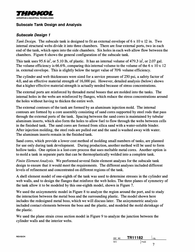
Tank Design. The subscale tank is designed to fit an external envelope of 6 x 10 x 12 in. Two internal structural webs divide it into three chambers. There are four external ports, two in each end of the tank, which open into the side chambers. Six holes in each web allow flow between the chambers. Figure 6 shows the general configuration of the subscale tank.
This tank uses 95.6 in3, or 5. 1 0 lb, of plastic. It has an internal volume of 479.3 irf, or 2.07 gal.The volume efficiency is 66.6%, comparing this internal volume to the volume of the 6 x 1 0 x 1 2 in. external envelope. This is slightly below the target value of 70% volume efficiency.
The cylinder and web thicknesses were sized for a service pressure of 250 psi, a safety factor of 4.0, and an effective material strength of 1 6,000 psi. However, detailed analysis (below) shows that a higher effective material strength is actually needed because of stress concentrations.
The external ports are reinforced by threaded metal bosses that are molded into the tanks. The internal holes in the webs are reinforced by flanges, which reduce the stress concentrations around the holes without having to thicken the entire web.
The external contours of the tank are formed by an aluminum injection mold. The internal contours are formed by a core assembly consisting of sand cores supported by steel rods that pass through the external ports of the tank. Spacing between the sand cores is maintained by tubular aluminum inserts, which also form the holes to allow fuel to flow through the webs between cells in the finished tank. The sand cores are formed from silica sand with a water-soluble binder. Mter injection molding, the steel rods are pulled out and the sand is washed away with water. The aluminum inserts remain in the finished tank.
Sand cores, which provide a lower cost method of molding small numbers of tanks, are planned for use only during tank development. During production, another method will be used to form hollow tanks. One option is a lost-core process that uses meltable metal cores. Another option is to mold a tank in separate parts that can be thermoplastically welded into a complete tank.
Finite Element Analysis. We performed several finite element analyses for the subscale tank design to ensure that it would meet the requirements. The different analyses included different levels of refinement and concentrated on different regions of the tank.
A shell element model of one-eighth of the tank was used to determine stresses in the cylinder and web walls, and to design the flanges that reinforce the web holes. The three planes of symmetry of the tank allow it to be modeled by this one-eighth model, shown in Figure 7.
We used the axisymmetric model in Figure 8 to analyze the region around the port, and to study the interaction between the metal boss and the surrounding plastic. The model shown here includes the redesigned metal boss, which we will discuss later. The axisymmetric analysis included contact elements between the boss and the plastic, and modeled the mold shrinkage of the plastic.
We used the plane strain cross section model in Figure 9 to analyze the junction between the cylinder walls and the interior webs.
REVISION DOC NO. TR11182 SEC I PAGE
7

THIOKOL AEROSPACE & INDUSTRIAL TECHNOLOGIES
The three-dimensional solid model in Figure 10 models a symmetric section of the whole tank, including an accurate representation of the boss. However, it uses rather coarse elements, and does not model fillets and fine details. It accounts for the effects of wall thickness better than the shell model.
Table 9 summarizes analysis input properties. The plastic properties are typical values for a 30% to 40% glass-reinforced PPA. Properties are shown for both aluminum and steel because analyses were done for both the original aluminum boss as well as the later steel boss.
· Analysis results are summarized in Table 10. The highest stress shown is 6477 psi (at the operating pressure of 250 psi) in the web in the narrow gap between the flange of the small hole and the web/cylinder junction, based on the three-dimensional solid analysis. The second highest stress is near the same location, in the web/cylinder junction fillet, based on the cross section analysis. The three-dimensional solid analysis did include some higher stresses, but they were very localized and were not expected to cause tank failure.
Based on the finite element analyses, an effective material strength of 25,900 psi would be needed to achieve the required 4.0 safety factor.
Tanks were molded of AMODEL A-1133 HS material. They were then burst tested, tests that will be discussed in more detail later. The average burst pressure was 427 psi, with a standard deviation of 53 psi. Based on the finite element analysis, this indicates a nominal effective strength of 11,000 psi.
Port Sealing
When the first burst test was done (Tank 4), we observed leakage around the molded-in metal bosses. We saw leakage even before pressure was applied. The original design assumed that mold shrinkage of the plastic would cause it to squeeze onto the boss, providing a tight metal to plastic seal. Apparently, however, the plastic does not bond to the metal, and the interface provides a leak path.
Prior to testing the other three tanks, we designed a fitting that threaded into the molded-in bosses, and sealed with an 0-ring against the plastic surface around the boss. Figure 11 shows the fitting design, and Figure 12 illustrates how it interfaces with the tank port.
We performed a finite element analysis of the fitting to determine how it would respond to changes in the temperature and pressure of the tank. The plot in Figure 13 shows how much the 0-ring gap opens as the tank is cooled. The maximum 0-ring gap opening is 0.0012 in. at -40°F. This reduces the 0-ring squeeze from 25% to 24%, which is not enough to affect the seal.
This fitting worked well. We observed no leakage in any of the other three tanks, even after I5,000 pressure cycles on Tank 6.
Intermediate Design
Keeping the following constraints and considerations in mind, we designed an intermediate subscale tank design.
• Keep stresses in plastic below I 0,000 psi at the design burst pressure of I 000 psi.
REVISION DOC NO. TR11182 SEC I PAGE
8

THIOKOL AEROSPACE & INDUSTRIAL TECHNOLOGIES
• Do not change any outer contours, which are controlled by the existing injection mold. Newmolds will be required for the internal cores.
• Facilitate manufacture by the metal lost-core process. Provide slope for complete drainage ofcore material, at least in the two side chambers.
• Assume no bonding between plastic and molded-in bosses. They must be retained by amechanical lock only, and must be restrained against rotation.
Figure 14 shows the resulting subscale tank. All the walls are thicker to compensate for the lower material strength. The inner contour of the domes allows the side chambers to drain completely through the ports when the tank is vertical. The middle chamber still cannot be drained completely, but this is not vital in a subscale design that is used only for testing.
We reduced the number of holes in the webs and relocated them to reduce unnecessary stress concentrations and improve drainage. The four holes in each web are now located in the corners of the domes, where tensile stresses in the web are reduced by the bending of the dome under pressure. They are located as close as possible to the extremities of the web to allow nearly complete liquid drainage from one chamber to another.
The boss is retained against blowout loads by its flange. An undercut angle on the edge of the flange prevents the boss from being pushed into the tank. It is restrained against rotation by six holes that are filled with plastic.
This tank design uses 171.5 iff or 9.14 lb of plastic and contains 403.0 iff or 1. 74 gal of internal volume. This is 80% more plastic than the original subscale design, an increase that was necessary to accommodate lower material strength. The volume efficiency is reduced from 66.6% to 56.0%, far below the target of 70%. Improvements in the effective plastic strength will be necessary to achieve a competitive design.
We did not build any tanks to this intermediate design.
Subscale Design 2
Tank Design. We prepared the second complete subscale tank design with the goal of reaching a design burst pressure of 1000 psi with the worst expected material properties. The design strength is 7200 psi. This is a lower bound estimate of the strength of AMODEL A-1133 HS, as molded in the tank configuration. Based on the burst tests of subscale tank design I, there was a 99% probability of the strength being greater than 7200 psi, as illustrated in Figure 15.
In redesigning the subscale tanks, the outer contour was kept the same, so no modifications of the injection mold were required. Because internal contours were changed in order to change the wall thicknesses and internal features, new molds for the sand cores had to be fabricated.
Figure 16 shows tank design 2. Wall thicknesses have increased to 0.57 in. in the cylinder, 0.53 in. in the internal webs, and 0.90 in. in the domes. The tank contains 265 irl, or approximately 14 lb of plastic. The internal volume is 308 irl, for a volume efficiency of 43%. The holes through the webs have been relocated and reduced in number to reduce the stress concentrations. This should also improve flow during molding.
Finite Element Analysis. To arrive at this design, we conducted a series of finite element analyses. In these analyses, the cylinder thickness, web thickness, y-joint fillet radius, and web
DOC NO . TR11182 lvoL REVISION
SEC I PAGE
9

FHIOICOL AEROSPACE & INDUSTRIAL TECHNOLOGIES
hole radius and location were adjusted to obtain a balanced design with maximum stresses below 7200 psi at 1000 psi pressure. Table 11 gives the results of each iteration.
These analyses used three-dimensional solid finite elements rather than shell elements, providing accurate results even in the junctions between the internal webs and the outer cylinders and domes. Stress contours at 1000 psi pressure for the final configuration are shown in Figures 17 and 18. The highest predicted stress is 7080 psi, somewhat lower than the target of 7200 psi, so the burst pressure was expected to exceed 1000 psi.
Full-Scale Tank Design
We designed a preliminary full-scale tank with the following constraints:
• Keep stresses in plastic below 10,000 psi at the design burst pressure of 1000 psi.
• Maximize tank volume in an envelope of 14 x 24 x 36 in.
• Facilitate manufacture by the metal lost-core process. Provide slope for complete drainage ofcore material.
• Assume no bonding between plastic and molded-in bosses. They must be retained by amechanical lock only, and must be restrained against rotation.
The result is shown in Figure 19. The design includes ports in both ends of all three chambers, providing improved support and alignment for the cores during injection molding, and facilitating complete drainage of the molten core material. Mter manufacture, the ports are designed to be closed by fittings that thread into the ports and seal with 0-rings against the outer face of the plastic, similar to those used for the burst tests on the subscale tanks.
This tank design uses 2495 in' or 133 lb of plastic and contains 7301 in' or 31.6 gal of internal volume. The volume efficiency is 60%, low compared to the target of 70%, but better than that of the intermediate subscale tank, which was designed with the same criteria.
Cost Model
We developed a cost model, implemented as an Excel spreadsheet, to estimate the relationship between material properties and tank cost, weight, and volume. The cost model includes strength criteria to hold internal pressure as well as toughness criteria to withstand external impact.
Thin wall membrane theory is used to estimate wall thicknesses for the webs, domes, and cylinders to hold the pressure. Transverse direction strength is the important material property for this criterion. For impact, closed form equations are used to approximate the cylinder wall deformation, stress, and strain under a point load, and to estimate the energy absorbed before cracking. This criterion accounts for yielding if the material is ductile. The important material properties for impact are the flow direction strength, modulus, and failure strain.
Using simplified tank geometry, the required wall thicknesses calculated from the strength and impact criteria are translated into material volume and internal volume. By comparing these calculations with the detailed design analyses of the subscale tanks, the calculations have been verified as reasonably accurate.
REVISION DOC NO . TR11182 SEC I PAGE
10

THIOKOL AEROSPACE & INDUSTR!AL TECHNOLOGIES
The primary end results of the cost model are the internal volume, tank weight, and tank cost. The internal volume can be expressed in total gallons, or as a volume efficiency, which is the internal volume divided by the volume of the rectangular external envelope. With the volume, weight, and cost, it is still difficult to rank different tank materials, because a lower cost can compensate for some lost volume or increased weight. An overall grade parameter that combines these three values has been proposed, as volume divided by cost times weight. Thus, more volume, lower cost, or less weight result in a higher overall grade. The units of the overall grade are in3 /$-lb.
Tables 12 through 14 give cost model calculations for an aluminum tank and for the two primary plastic candidates . These cost models are based on the best estimates of material properties after testing the first subscale tank design. As we will discuss, these properties were not achieved when the thicker second design was fabricated. Table 15 shows the cost model for a "target" material. This represents a hypothetical material custom developed for pressure tanks.
The results are compared in Figure 20. The volume efficiency of the plastic tanks is lower than the aluminum baseline. Because the plastics are not as strong as aluminum, thicker walls are necessary, which displaces some of the fuel volume. Likewise, the weight of the plastic tanks is higher, although the target material would approach the weight of an aluminum tank. The advantage of injection-molded tanks is in the cost, as the figure shows. The plastic tanks approach half the cost of an aluminum tank. With this cost advantage, plastic tanks have the potential of a higher overall grade than aluminum, also shown in Figure 20.
System Fabrication
Subscale Design 1
First Molding Run
Injection molding was done at Hettinga Equipment, in Des Moines, Iowa. In the first molding session, on January 24-25, 1996, we planned to mold with two candidate materials: RTP 2399 x 68911A (PU), and AMODEL A-1133 HS (PPA). However, because of molding problems, we used only the PU material.
A single set of aluminum cores was to be used for the initial molding, to set process parameters. This required cutting the plastic part into several pieces to remove the cores prior to molding the next part. The first part molded with the PU material was overfilled because of a miscalculation of shot size. This resulted in substantial flashing and thicker walls. The part filled completely, with no visible voids. It was much more difficult than expected to cut this tough plastic off of the mandrels. Rather than delaying the rest of the molding while cutting the plastic, we decided to go ahead with the sand cores. Only four sets of sand cores were available, and we planned to mold two with each material.
The first part made on a sand mandrel was only about 80% filled. However, muc h more serious than the partial filling was the fact that the sand cores were shifted and partially fractured by the injection pressure. As shown in Figure 21, injection was through a single gate at the center of one end of the part. Pressures at that end caused the cores to push toward the opposite end. The
REVISION DOC NO . TR11182 SEC I PAGE
i VOL
I I
THIOKOL AEROSPACE & INDUSTRIAL TECHNOLOGIES
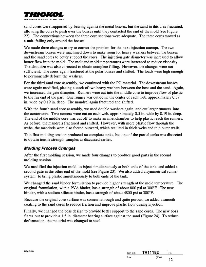
sand cores were supported by bearing against the metal bosses, but the sand in this area fractured, allowing the cores to push over the bosses until they contacted the end of the mold (see Figure 22). The connections between the three core sections were adequate. The three cores moved as a unit, failing only around the bosses.
We made three changes to try to correct the problem for the next injection attempt. The two downstream bosses were machined down to make room for heavy washers between the bosses and the sand cores to better support the cores. The injection gate diameter was increased to allow better flow into the mold. The melt and mold temperatures were increased to reduce viscosity. The shot size was also corrected to obtain complete filling. However, the changes were not sufficient. The cores again fractured at the polar bosses and shifted. The loads were high enough to permanently deform the washers.
For the third sand core assembly, we continued with the PU material. The downstream bosses were again modified, placing a stack of two heavy washers between the boss and the sand. Again, we increased the gate diameter. Runners were cut into the middle core to improve flow of plastic to the far end of the part. One runner was cut down the center of each web, approximately 0.37 in. wide by 0.19 in. deep. The mandrel again fractured and shifted.
With the fourth sand core assembly, we used double washers again, and cut larger runners into the center core. Two runners were cut on each web, approximately 0.5 in. wide by 0.19 in. deep. The end of the middle core was cut off to make an inlet chamber to help plastic reach the runners. As before, the mandrels fractured and shifted. However, with more plastic flow through the webs, the mandrels were also forced outward, which resulted in thick webs and thin outer walls.
This first molding session produced no complete tanks, but one of the partial tanks was dissected to obtain tensile strength samples as discussed earlier.
Molding Process Changes
After the first molding session, we made four changes to produce good parts in the second molding session.
We modified the injection mold to inject simultaneously at both ends of the tank, and added a second gate in the other end of the mold (see Figure 23). We also added a symmetrical runner system to bring plastic simultaneously to both ends of the tank.
We changed the sand binder formulation to provide higher strength at the mold temperature. The original formulation, with a PV A binder, has a strength of about 800 psi at 300°F. The new binder, with a sodium silicate binder, has a strength of about 4800 psi at 300°F.
Because the original core surface was somewhat rough and quite porous, we added a smooth coating to the sand cores to reduce friction and improve plastic flow during injection.
Finally, we changed the boss design to provide better support to the sand cores. The new boss flares out to provide a 1.5 in. diameter bearing surface against the sand (Figure 24). To reduce deformation, the material was changed to steel.
DOC NO . TR11182 lvoL REVISION
S E C I PAGE
1 2

THIOKOL AEROSPACE & INDUSTRIAL TECHNOLOGIES
Second Molding Run
These molding process changes resulted in a successful second molding session on March 20-21, 1996. We prepared ten sets of sand cores for this session, and molded tanks from AMODEL A-1133 HS. The changes solved the problem of the sand cores shifting during injection.
Photos of the mold are shown in Figures 25 through 28. Figure 25 shows half the mold, prior to inserting the sand cores. Figure 26 shows the sand cores in the mold. They are supported by steel rods that are held in place by toggle clamps. Figure 27 shows the runner system, which provides balanced flow to the two ends of the mold. Figure 28 shows the molded part just after opening the mold. The weld line where the two flow fronts meet at the middle of the part is visible in this photo.
The rrrst part was incompletely filled. We cut apart the second part to confirm that it filled completely. We used the same molding process parameters on the next seven parts. On the final part, higher injection rates and pressures were used, which produced a slightly smoother finish. Several of the parts had dark streaks, possibly caused by local overheating of the resin during injection. These streaks were most evident on the last part. Most of the parts also have some chalky surface areas on the domes, probably caused by local concentration of glass fibers. A knit line is clearly visible at the midplane, where the two main injection fronts meet. More complicated knit lines are visible on the internal webs, where plastic flows around the web holes and meets on several fronts.
Following molding, the tanks were annealed at 300°F for a minimum of 2 hours at the recommendation of Hettinga Equipment representatives.
After molding, Tanks 1 and 2 were cut up immediately to confirm complete interior filling. Tanks 3 and 7 were dissected for tensile bars, flexure bars, and impact tests. Tanks 4, 8, and 10 were burst tested. Tank 6 was pressure cycled and burst. Tanks 5 and 9 are being used for display.
Subscale Design 2
Starting on May 19, 1997, and rmishing on May 22, 21 tanks of subscale design 2 were molded at Hettinga. Fourteen tanks were molded with AMODEL AS-1133 HS, and seven with FORTRO N 0214 C l . Table 16 gives the results of the molding, which encountered serious problems in the form of shrinkage cracks, voids, weak molding weld lines, and collapsed aluminum inserts.
The shrinkage cracks are a result of the plastic part being molded around and completely enclosing a rigid core. These cores are made of silica sand with a water-soluble sodium silicate binder. The sand cores are rigid and have low thermal expansion. Because the plastic shrinks significantly after molding, and the cores do not, large stresses built up in the plastic, resulting in cracks in many of the tanks. Shrinkage is accentuated by thicker sections, and did not cause apparent problems in the original tank design. In the first few tanks, the sand was washed out after the tanks had cooled, by immersing the whole tank in water and allowing the cores to soften gradually. In later tanks, the sand was washed out as soon as possible after molding in an attempt
to allow the plastic to shrink more freely. Water was injected through a hose to soften and wash out the sand internally without cooling the plastic too rapidly. This process was only partly successful. Some tanks cracked before the sand could be washed out. Others cracked audibly during wash out. Others cracked several hours or more after wash out, although internal cracks
REVISION DOC NO . TR11182 SEC I PAGE
1 3

THIOICOL AEROSPACE & INDUSTRIAL TECHNOLOGIES
were probably present earlier. Two of the FORTRON tanks that were shipped without cracks were found to have cracks after going through the annealing treatment.
The first tank molded was cut into quarters to check the internal filling. We found several voids near the main weld line, as shown in Figure 29. The largest voids are about 0.45 in. x 0.27 in. in size. Mter molding a few more tanks, the molders felt that the voids were caused because the runners were freezing off before the mold was completely packed. To allow better flow through the runners, the mold was pulled off of the machine, and the runners and sprues were increased in size. This mold modification was completed before molding Tank 8. It did not completely solve the void problem.
Weak molding weld lines were apparent in many of the parts. Many of the shrinkage cracks occurred along the main weld line. Figure 30 shows an interesting flow pattern at the weld line in one of the FORTRON tanks. This looked like a potential weak spot, but the burst test fracture did not go through this spot. In some of the FORTRON tanks, glossy fracture surfaces were seen along the weld line, indicating a cold weld.
When some of the sand cores were being washed out, we could not get cross flow of water from one side cell to the other. The center cell was apparently sealed. We cut open one of these tanks (number 5), and found that the aluminum inserts that form the holes through the webs had crushed under the injection pressure. This problem was solved first by replacing the aluminum tubes with steel. Later we simply filled the aluminum tubes with loose sand to prevent them from collapsing.
Fabrication Methods
Cup Welding
The shrinkage problems encountered in molding the subscale tanks may have resulted from the part completely enclosing a rigid core. Molding the tank in halves would result in some freedom for axial shrinkage, reducing shrinkage problems. This would also simplify tank fabrication by eliminating the need to mold cores and remove them after molding the tank.
Some type of joining process would be required to assemble the tank halves, producing a hermetic and structural connection. Thermoplastic welding is one option. Initial trials have been done with this process.
Four materials were tested in a welded bottle configuration, as shown in Figure 3 1 . Forward Technology Industries, Inc., made the welds using a hot plate process. The weld is at the thinnest wall section of the bottle, giving it a severe test. In most cases the bottles failed with a longitudinal crack, not along the circumferential weld. Table 17 summarizes the material strengths computed from the measured burst pressures.
Even though the failures did not follow the weld, the welded bottles were generally weaker than the monolithic tubes. For AMODEL A- 1 133 HS, the welded bottles were substantially weaker, as shown in Figure 32. For RTP 4005, the welded bottles approached the strength of the nonwelded tubes, as shown in Figure 33. If welded tank fabrication is found to be the best approach, a change in material would be necessary.
REVISION DOC NO . TR11182 SEC I PAGE
14

THIOKOL AEROSPACE & INDUSTRIAL TECHNOLOGIES
Process Improvement
Our work has shown that the potential strength of the plastics is not being obtained in the molded tanks. Processing modifications that would improve the effective strength of the molded plastics are needed. We discussed this problem with an Amoco material engineer, who suggested that we contact TherMold Partners in Stamford, Connecticut, and investigate its vibrational molding technique.
_ Vibrational Molding
We held a meeting with representatives of TherMold Partners to investigate its vibrational molding technology, known as RHEOMOLDINGM. This technology has the potential toimprove the effective material strength in our conformable tanks, making lighter, more competitive designs feasible. The potential is good enough that feasibility tests should be planned in the future.
Data published by TherMold shows significant strength increases (on the order of 20%) for various unfilled materials with RHEOMOLDING. A dramatic strength increase of 1 1 1% was seen for a 45%-glass-fiber-filled PPA molded with a weldline. An improvement in weldline strength is important in the conformable tanks because weldlines are formed as a result of flow around the boss inserts and web holes, as well as at the part midplane caused by injection from both ends. RHEOMOLDING also reduced the variability of strength, especially in samples with a weldline.
To date, TherMold has tested samples only in the direction of flow. Future feasibility tests should start with molding and testing transverse direction lab samples. If these samples show significant improvement in the transverse direction strength, the next step would be to test RHEOMOLDING on the subscale tank. In the laboratory testing phase, a matrix of processing parameters would be run to identify the optimum conditions. Processing parameters include the frequency, amplitude, and duration of vibration. The sample thickness would also be varied to identify scale-up effects. Testing on subscale tanks would then require purchasing a limited license for the RHEOMOLDING technology, and installing the RHEOMOLDING equipment on a molding machine at Hettinga (or another molder).
Experimental Program
Subscale Tank Design 1
Burst and Cyclic Pressure Tests
Four tanks of design 1 were burst tested, and the results are given in Table 1 8. The average burst pressure for the four tanks was 427 psi. One tank (number 8) burst at a significantly lower pressure than the other three. Because of a data acquisition problem, the exact burst pressure was not recorded for this tank, but based on manual observation of the pressure gage and correlation with a strain gage, the burst pressure was about 350 psi.
Tank 10 was molded with higher injection rates and pressures than the other tanks. Although it had the highest burst pressure at 464 psi, the difference was not large enough to be significant.
S E C I PAGE
l voL REVISION
DOC N O . TR11182
15

THIOKOL AEROSf'lii.CE & INDUSTRIAL TECHNOLOGIES
Tank 6 went through 15,000 pressure cycles, but still burst at 459 psi, indicating no degradation caused by pressure cycling.
It is not possible to identify for certain where failure initiated in these tanks. However, all four tanks have in common a failure along the junction between the internal web and the outer cylinder walls near the middle of the tank, as shown in Figure 34. This appears to be the most likely failure location. This location agrees with the location of maximum stresses in the finite element analyses. From this fracture, cracks propagate across the web and into the cylinder and dome regions. In this location, the stress at the average burst pressure of 427 psi is 1 1 ,000 psi based on finite element analysis. This agrees very well with the circumferential direction strength, 10,700 psi, measured from dissected samples.
Although all these tanks have a prominent mid-length knit line because plastic was injected from both ends, in only one case does a fracture follow this knit line. On Tank 8, a crack runs axially the whole length of the tank on one side cylinder, and takes a lateral jog of about 2 in. along the knit line (see Figure 35). Similar axial cracks on the other tanks pass straight through the knit line. It appears that this knit line is normally not detrimental in these tanks. Indeed, the dissected samples show that the knit line has about the same strength as the transverse to flow direction in the material.
Impact Tests
We performed impact tests on Tanks 3 and 7, which were also the source for the dissect samples. Each tank was rtrst cut in half longitudinally through the middle chamber. One half was reserved intact for impact testing; the other half was cut into lab samples.
Impact tests were done on a drop weight tester with a 0.5 in. diameter hemispherical impacter, instrumented to measure loads and energies. The half tank rested with the cut surface flat on a table, and the impacter struck it on the cylindrical part of the side chamber. Four impacts were made at different locations on each half-tank. Table 19 summarizes the available energy at impact, the energy absorbed by the tank, and observations of damage at the impact site.
The critical impact energy level for the subscale tank is about 5 foot-pounds (ft-lb ). If the available impact energy is below 5 ft-lb, no damage is expected. Between 5 and 8 ft-lb, local cracking is likely. Above 8 ft-lb, the tank is likely to be pierced.
The full-scale tank needs to be able to withstand an impact of 22. 1 ft-lb, based on Reference 1 . The critical value for the subscale tank is well below this, indicating that impact is a significant design constraint. Scaling the tank up to full size will increase the critical value, but it may also be necessary to select a tougher material, possibly at the expense of some tensile strength.
Subscale Tank Design 2
Burst Tests
Burst tests were done for five tanks of subscale design 2: three AMODEL tanks and two FORTRON tanks. Results were given in Table 16.
I PAGE
JvoL REVISION DOC NO . TR11182 SEC
16

THIOICOL AEROSPACE & INDUSTRIAL TECHNOLOGIES
Burst test results for the AMODEL material were low and variable. In the original subscale tank design, with 0. 19 in. thick cylinder walls, the average burst pressure for AMODEL was 427 psi. In the current design, with the wall thickness tripled to 0.57 in., the average burst pressure decreased to just 302 psi. The low burst pressures probably result from internal shrinkage damage. Failure modes were different in all three tanks. Tank 2 burst at 1 89 psi. It started leaking along the main weld line, but failed with a longitudinal split along one side. Tank 14 failed at 289 psi with a local crack along the main weld. Tank 1 3 burst at 430 psi, breaking into two halves along the main weld line.
The FORTRON material produced much better results, but still below the 1000 psi target The two tanks that could be burst tested failed at 643 and 839 psi, for an average of 741 psi. Failure modes were quite consistent. Both tanks fragmented into numerous pieces, with cracks radiating from the intersection between the main weld line and the web/cylinder y-joint (see Figure 36). We found voids in both tanks at this location. Tank 21 (with the higher burst pressure) had a poor weld line in this area, indicated by smooth, glossy internal surfaces (see Figure 37). Tank 20 did not have similar indications of a weak weld. It did have porosity (numerous small voids) in both domes (see Figure 38), although failure did not appear to begin there. One void near the weld line in Tank 2 1 had a darkened interior, as though it had been burned or contaminated (see Figure 39).
Accomplishments
In Phase I of the Low-Cost Conformable Storage project, we evaluated materials, designed a subscale tank, and fabricated and tested several copies of the tank. Tank burst pressures were lower than planned, and we found that the effective material strength as molded in the tank was much lower than expected. Based on the lower effective material strength, the subscale tank was redesigned, and a similar design was produced for a full-scale tank. It appears that these tanks would not be competitive because of the low volume efficiency and large amount of material required.
In Phase IT, we redesigned the subscale tank in an attempt to reach the target burst pressure with conservative material properties. The target burst pressure was not achieved because the thicker walls caused processing problems. Most of the tanks developed obvious shrinkage cracks after molding, and the few tanks that could be burst tested failed at low pressures because of internal damage.
Phase II also encompassed a preliminary investigation of technologies that may help produce a viable tank. Thermoplastic welding was shown to be capable of producing a useful pressure vessel. Research into vibrational molding indicates a potential to improve as-molded material properties, but would need to be further explored with suitable tests.
The project did demonstrate, in one of the tanks, a burst pressure exceeding three times the operating pressure for LPG. It demonstrated the moldability of conformable pressure tanks , and also identified some concerns with the molding process. We developed a successful method to seal the ports, and tested it in a cyclic pressure test.
Based on this work, we now understand the limits of injection-molded plastics for pressure tanks better. Processing flow, weld lines, and shrinkage are important. The strength of reinforced plastics is highly anisotropic. Toughness and impact tolerance are an important design concern.
SEC I PAGE
lvoL REVISION DOC NO . TR11182
17

THIOKOL AEROSPACE & INDUSTRIAL TECHNOLOGIES
Temperature sensitivity is significant, as plastics lose strength at high temperatures, and become brittle at low temperatures. Thermoplastics are injected at extremely high pressures, making it necessary to use very strong, rigid cores to form hollow cells. The injection-molding process can be difficult to scale up. Increases in wall thickness create higher shrinkage and increase cycle times by requiring longer cooling. Larger parts also require huge presses to contain the injection pressure.
The Future
Achieving traditional safety factors and light weight in plastic tanks requires an increase in the strength of the material. A likely way to increase the strength is to reinforce the material with fabric. This could be done in a structural reaction injection-molding (SRIM) process, or perhaps as a modification to thermoplastic injection molding. Another option is to pursue the development of higher strength thermoplastics.
Structural Reaction Injection Molding
The SRIM process is used commercially for producing large structural parts. It involves placing a reinforcement preform into a mold, and then injecting a thermoset resin into the mold. The resin has low viscosity and is injected at low pressure, typically less than 1 00 psi, allowing the use of less expensive mold tooling.
Figure 40 shows a concept for a SRIM conformable tank. This concept starts with rotationally molded liners to form the hollow cavities. Braided fiber reinforcement preforms would be placed over the liners, and the liners would be attached together, then placed into the mold for injection of the resin.
In this concept, the rotationally molded liners provide sealing for the fuel. The braided reinforcement carries most of the load, and the resin keeps the reinforcement in place.
This concept has several advantages. The existing subscale injection mold could be adapted for SRIM molding. The reinforcement provides the strength, reducing the requirements for the plastic. The liners form the cavities and seal the tank, so there are no cores to remove after molding. Tooling cost is relatively low for both rotational molds and SRIM molds, because they operate at low pressure. SRIM is suitable for scaling up to large parts.
One challenge is the joining and sealing of the separate cell liners. The liners need to be connected together with ports that allow fluid flow but are completely sealed. This can probably be done with a thermoplastic welding process.
Higher Strength Thermoplastic Development
Developing higher strength thermoplastics is a more challenging approach, but an important approach, because in the long run, it has the potential to produce the lowest cost tank. It would also have great benefit for many other applications that require higher strength thermoplastics.
Initial target material properties have already been defined and are listed in Table 20. These targets would no doubt be refined as the program progressed.
REVISION DOC NO . TR1 1 1 82 SEC I PAGE
18
THIOICOL AEROSPACE & INDUSTRIAL TECHNOLOGIES
This development project would carry a high risk of failure and a relatively high expense. There is no guarantee that sufficient improvements could be made in the material properties. Numerous tanks would have to be molded to confirm progress, because plastics are very sensitive to the molding process.
Fabric-Reinforced Thermoplastic Injection Molding
The injection molder, Hettinga Technologies, has suggested incorporating fabric reinforcement in an injection-molded tank, a concept illustrated in Figure 41 . The tank would be molded in halves to reduce shrinkage problems and improve cycle times. Fabric reinforcement preforms would be placed into the mold prior to injection, and the plastic would flow into the reinforcement during injection. The tank halves would be joined by adhesive lap joints or thermoplastic welding. Various joining options are illustrated in Figures 42 through 44.
This approach has some advantages. The reinforcement provides the strength, so the thermoplastic resin could be selected for easy processing, good sealing, chemical resistance, toughness, and low cost This approach also builds very directly on the injection-molding experience from this project.
There are also some challenges to this approach. It may be difficult to keep the reinforcement in place at the high injection pressures. Joining the tanks halves reliably will be a concern. New molds would probably be required for a development project, because the current mold is designed for monolithic tanks.
Conclusions
This project demonstrated the feasibility of conformable plastic pressure tanks, but also identified several difficulties. Several options are available to develop increased strength, which will make the conformable plastic tanks an attractive option.
References
I. "American National Standard for Basic Requirements for Compressed Natural Gas Vehicle (NGV) Fuel Containers, "ANSI/AGE NGV2-1992, August 6, 1992.
2. Federal Motor Vehicle Safety Standard (FMVSS) No. 304, Compressed Natural Gas FuelContainer Integrity, September 1994.
3. Supplemental Notice of Proposed Rulemaking (SNPRM), National Highway Traffic SafetyAdministration (NHTSA), Federal Register Excerpt 59 FR 65299 No. 242, December 19,1994.
SEC I PAGE
lvoL REVISION DOC NO . TR11182
19

THIOKOL AEROSPACE & INDUSTRIAL TECHNOLOGIES
Table 1, Material Properties Data
Chemical Name Polyphenylene Polyphenylene Polyphenylene Polyphenylene Sulfide Sulfide Sulfide Sulfide
Commercial Name Ryton R-4XT RTP 1 301 RTP 1 305 FORTRON 0205 P4
Manufacturer Phillips RTP RTP Hoechst Celanese
Filler Glass Fiber 4Q'>k Glass Fiber 1 0"/o Glass Fiber 30"/o None
Special Features Dimensional stabilit) Aame retardant, Aame retardant, high flow, low flash & good moldability heat & chemical heat & chemical
resistant resistant
Processing Temp OF 6 1 0 6 1 0 560
Mold Shrinkage, 1/8" in/in 0.0060 0.0020 0.01 20
Mold Shrinkage, 1/4" in/in
Melting Point OF
Density lb/ft3 1 03.0 88.0 99.3 84.3
Tensile Str, Yield lb/in2 3.7E+3 1 7.0E+3 1 2.5E+3
Tensile Str, Break lb/in2 29.0E+3 1 2.5E+3
Elongation, Yield %
Elongation, Break "'o 1 .00 4.00
Tensile Modulus lb/in2 1 .0E+6 1 .9E+6
Flexural Str, Yield lb/in2 41 .0E+3 1 2.0E+3 25.0E+3 21.0E+3
Flexural Modulus lb/in2 2.0E+6 850.0E+3 1 .5E+6 600.0E+3
Compressive Str lb/in2 34.0E+3 1 0.0E+3 22.0E+3
lzod, Notched, R.T. ft-lb/in 1 .70 0.80 1 .60 0.50
Linear Thermai Exp in/in/°F 20.0E-6 1 4.0E-6 23.0E-6
Continuous Svc Temp OF
Defl Temp, 264 psi OF 500 450 500 221
Defl Temp, 66 psi OF 500 500 390
Water Absorp, 24 hr % 0.0200 0.0200 0.0200
Cost $/lb 4.44
Thiokol Tests:
Tensile Stmgth, 75°F lb/in2 27.0E+3
Elongation, 75°F % 1 .40
Modulus, 75°F lb/in2 2.30E+6
Tensile Stmgth, 1 80°F lb/in2 2 1 .5E+3
Elongation, 1 80°F % 1 .52
Modulus, 1 80°F lb/in2 2.21 E+6
Weld Stmgth, 75°F lb/in2 6.2E+3
Weld % of full strngth % 23
Strength at 1 80°F after LPG lb/in2 1 9.5E+3
Strength at 1 80°F after CNG lb/in2 1 8.3E+3
Aging in fuels with .5% strain no damage
Creep Stmgth, 1 80°F, 1 0000 sec lb/in2
Hoop strength in tubes, 75°F lb/in2 1 3.4E+3
Hoop strength in tubes, 180°F lb/in2
REVISION DOC NO . TR11182 SEC I PAGE
20

THIOICOL AEROSPACE & INDUSTRIAL TECHNOLOGIES
Table 1, Material Properties Data (Continued)
Chemical Name Polyphenylene Polyphenylene Polyphthalamide Polyphthalamide Sulfide Sulfide
Commercial Name FORTRON 021 4 FORTRON 1 1 40 AMODEL AMODEL C1 L6 A-1 1 1 5 HS A-1 1 33 HS
Manufacturer Hoechst Hoechst Amoco Amoco Celanese Celanese
Filler None Glass 40% Glass 1 5% Glass 33%
Special Features Unreinforced, natura Heat stabilized, low Heat stabilized, lOY color moisture absorption moisture absorptior
exc chem resist exc chem resist
Processing Temp OF 590 590 605 605
Mold Shrinkage, 1/8" in/in 0.0120 0.0020 0.0060 0.0020
Mold Shrinkage, 1/4" in/in
Melting Point OF 590 590
Density lb/ft3 84.3 1 02.0 78.6 89.3
Tensile Str, Yield lb/in2 1 2.5E+3 29.0E+3
Tensile Str, Break lb/in2 1 2.5E+3 29.0E+3 1 8.6E+3 32.0E+3
Elongation, Yield lo!o Elongation, Break lo!o 4.00 2.00 2.00 2.50
Tensile Modulus lb/in2 2.1 E+6 1 .2E+6 1 .9E+3
Flexural Str, Yield lb/in2 21 .0E+3 40.0E+3 24.8E+3 46.0E+3
Flexural Modulus lb/in2 600.0E+3 2.0E+6 900.0E+3 1 .7E+6
Compressive Str lb/in2 30.0E+3 40.0E+3
zod, Notched, R.T. ltt-lblin 0.50 1 .90 0.80 2.1 0
dnear Thermai Exp in/in/°F 259.0E-6 12.0E-6 1 9.0E-6 1 3.0E-6
Continuous Svc Temp OF 356 365
Defl Temp, 264 psi OF 221 500 531 545
Defl Temp, 66 psi OF 390 536 558 567
Water Absorp, 24 hr % 0.0 1 00 0.0200 0.3000 0.2100
Cost �b 5.65 3.52 2.75 2.75
Thiokol Tests:
Tensile Stmgth, 75°F lb/in2 1 7.7E+3 31 .6E+3
Elongation, 75°F % 1 .75 2.24
Modulus, 75°F lb/in2 1 .07E+6 1 .92E+6
Tensile Stmgth, 1 80°F lb/in2 1 6.3E+3 25.9E+3
Elongation, 1 80°F % 1 .90 2.59
Modulus, 1 80°F lb/in2 1 .03E+6 1 .77E+6
Weld Stmgth, 75°F lb/in2 1 1 .3E+3 14.7E+3
Weld o/o of full strngth Yo 64 47
Stren gth at 1 80°F after LPG lb/in2 1 6.0E+3 25.2E+3
Strength at 1 80°F after CNG lb/in2 1 6.0E+3 24.9E+3
Aging in fuels with .5% strain no damage no damage
Creep Stmgth, 1 80°F, 1 0000 sec lb/in2 1 3. 1 E+3 1 9.1 E+3
Hoop strength in tubes, 75°F lb/in2 7.8E+3 14. 1 E+3
Hoop strength in tubes, 1 80°F l1b/in2
REVISION DOC NO . TR11182 SEC I PAGE
21

THIOICOL AEROSPACE & INDUSTRIAL TECHNOLOGIES
Table 1, Material Properties Data (Continued)
Chemical Name Polyphthalamide Polyphthalamide Polyphthalamide Polyphthalamide Commercial Name AMODEL AMODEL RTP 4001 RTP 4005
AS-1 133 HS A-1 145 HS Manufacturer Amoco Amoco RTP RTP Filler Glass 33% Glass 45% Glass Fiber 10% Glass Fiber 30% Special Features High heat dell temp Heat stabilized, low High strength & stiff, High strength & stiff
modulus, stmgth, & moisture absorption Heat dell temp, Heat defl temp, creep resist;thick exc chem resist thermal stability thermal stability
walls
Processing Temp OF 605 605 Mold Shrinkage, 1/8" in/in 0.0040 0.0020 Mold Shrinkage, 1/4" in/in Melting Point OF 590 590 Density lb/ft3 91 . 1 97.4 79.3 88.7 Tensile Str, Yield lb/in2 1 3.5E+3 29.0E+3 Tensile Str, Break lb/in2 32.0E+3 37.5E+3 Elongation, Yield }/o 1 .00 2.00 Elongation, Break *' 2.50 2.60 Tensile Modulus lb/in2 1 .9E+6 2.5E+3 1 .0E+6 1 .9E+6 Flexural Str, Yield lb/in2 46.0E+3 52.6E+3 Flexural Modulus lb/in2 1 .7E+6 2.0E+6 900.0E+3 1 .6E+6 !Compressive Str lb/in2 40.0E+3 45.5E+3 zod, Notched, R.T. ift-lb/in 2.10 2.50 0.60 1 .80
1Linear Thermal Exp in/in/°F 1 3.0E-6 S.OE-6 21 .0E-6 1 3.0E-6 Continuous Svc Temp OF 365 365 Defl Temp, 264 psi OF 545 549 420 530 Defl Temp, 66 psi OF 567 574 Water Absorp, 24 hr }/o 0.2100 0.1 200 :cost $/lb 2.85 2.75
IThiokol Tests: Tensile Stmgth, 75°F lb/in2 35.1 E+3 !Elongation, 75°F }/o 2.53 !Modulus, 75°F lb/in2 2.23E+6 Tensile Stmgth, 1 80°F lb/in2 26.1E+3 Elongation, 1 80°F }/o 3.23 Modulus, 1 80°F lb/in2 1 .89E+6 Weld Stmgth, 75°F lb/in2 14.5E+3 Weld % of full strngth }/o 41 Strength at 180°F after LPG lb/in2 25.6E+3 15trength at 180°F after CNG lb/in2 25.4E+3 Aging in fuels with .5% strain no damage Creep Strngth, 180°F, 1 0000 sec lb/in2 !Hoop strength in tubes, 75°F lb/in2 10.8E+3 1 1 .2E+3 15.2E+3 jHoop strength in tubes, 180°F lb/in2
SEC I PAGE
l voL REVISION DOC NO . TR11182
22

THIOICOL AEROSPACE & INDUSTRIAL TECHNOLOGIES
Table 1, Material Properties Data (Continued)
Chemical Name Polyphthalamide Polyamide-Nylon Polyurethane Polyester (LCP} 6/6
Commercial Name RTP 4007 RTP 207H RTP 2399 X Vectra A950 6891 1 A
Manufacturer RTP RTP RTP Hoechst Celanese
Filler Glass Fiber 40% Glass Fiber 40% Glass Fiber 40"/o Special Features High strength & stiff High impact High impact, Low Not for injection
Heat defl temp, water absorption molding thermal stability
Processing Temp OF 550 500 545 Mold Shrinkage, 1/8" in/in 0.0020 0.0010 0.0010 0.0020 Mold Shrinkage, 1/4" in/in 0.0030 0.0030 0.0020 MeHing Point OF 536 Density lb/ft3 95.5 88.0 94.0 �ensile Str, Yield lb/in2 30.0E+3 21.0E+3 27.0E+3 24.0E+3 [�"ensile Str, Break lb/in2 24.0E+3 Elongation, Yield Yo 2.00 3.30 2.40 Elongation, Break Yo 3.00 Tensile Modulus lb/in2 2.2E+6 1 .6E+6 1 .8E+6 1 .4E+6 Flexural Str, Yield lb/in2 40.0E+3 32.0E+3 65.0E+3 24.5E+3 Flexural Modulus lb/in2 2.0E+6 1 .2E+6 1 .3E+6 1 .3E+6 Compressive Str lb/in2 23.8E+3 lzod, Notched, R.T. ft-lb/in 2.00 4.00 8.00 10.00 Linear Thermai Exp in/in/°F 1 0.0E-6 9.0E-6 Continuous Svc Temp OF Defl Temp, 264 psi OF 535 480 200 356 Defl Temp, 66 psi OF 495 Water Absorp, 24 hr � 0.2000 0.6000 0.0140 0.0000 Cost $/lb 3.1 9
kol Tests: Tensile Stmgth, 75°F lb/in2 31 .4E+3 23.4E+3 22.1 E+3 Elongation, 75°F Yo 2.01 3. 12 2.00 Modulus, 75°F lb/in2 2.02E+6 1 .38E+6 1 .40E+6 Tensile Stmgth, 1 80°F lb/in2 24.5E+3 14.4E+3 4.4E+3 Elongation, 1 80°F Yo 2.48 6.61 5.77 Modulus, 1 80°F lb/in2 1 .90E+6 620.00E+3 253.00E+3 Weld Stmgth, 75°F lb/in2 Weld % of full strngth Yo Strength at 180°F after LPG lb/in2 Strength at 1 80°F after CNG lb/in2 Aging in fuels with .5% strain Creep Stmgth, 1 80°F, 10000 sec lb/in2 Hoop strength in tubes, 75°F lb/in2 5.0E+3 Hoop strength in tubes, 1 80°F lb/in2 8.5E+3
SEC I PAGE
l voL REVISION DOC NO . TR11182
23

THIOICOL AEROSPACE & INDUSTRIAL TECHNOLOGIES
Table 1, Material Properties Data (Continued)
Chemical Name Polyester (LCP) Polyester (LCP) Polyester (LCP) Polyester (LCP) Commercial Name Vectra A1 15 Vectra A130 Xydar G-540 Xydar G-930 Manufacturer Hoechst Hoechst Amoco Amoco
Celanese Celanese Filler Chop Glass 1 5% Chop Glass 30% Glass Glass Special Features very easy flow high strength,
processability & flame res.
Processing Temp OF 520 545 620 Mold Shrinkage, 1/8" in/in 0.0010 Mold Shrinkage, 1/4" in/in Melting Point OF 536 535 590 610 Density lb/ft3 99.9 106.0 99.8 [rensile Str, Yield lb/in2 28.0E+3 30.0E+3 [rensile Str, Break lb/in2 28.0E+3 30.0E+3 21 .2E+3 1 9.6E+3 Elongation, Yield � Elongation, Break � 3.00 2.00 1 .50 1 .60 [rensile Modulus lb/in2 1 .9E+6 2.4E+6 2.9E+6 2.7E+6 Flexural Str, Yield lb/in2 30.0E+3 37.0E+3 27.0E+3 25.0E+3 Flexural Modulus lb/in2 1 .6E+6 2.1 E+6 2.3E+6 2.0E+6 Compressive Str lb/in2 lzod, Notched, R.T. �-lb/in 5.50 2.80 8.30 1 .80 Linear Thermal Exp in/in/°F 2.8E-6 7.0E-6 7.0E-6 Continuous Svc Temp �F Defl Temp, 264 psi OF 417 446 466 520 Defl Temp, 66 psi OF !Water Absorp, 24 hr Yo 0.0000 0.0100 Cost �b 1 1 .60 9.00 6.95 7.30
IThiokol Tests: lfensile Stmgth, 75°F lb/in2 Elongation, 75°F Yo Modulus, 75°F lb/in2 Tensile Stmgth, 180°F lb/in2 Elongation, 1 80°F l<>/o Modulus, 1 80°F lb/in2 Weld Stmgth, 75°F lb/in2 Weld % of full strngth � Strength at 180°F after LPG lb/in2 Strength at 180°F after CNG lb/in2 Aging in fuels with .5% strain Creep Stmgth, 1 80°F, 10000 sec lb/in2 Hoop strength in tubes, 75°F lb/in2 17.3E+3 6.3E+3 Hoop strength in tubes, 180°F lb/in2 9.2E+3 4.6E+3
SEC I PAGE
l voL REVISION DOC NO . TR11182
24
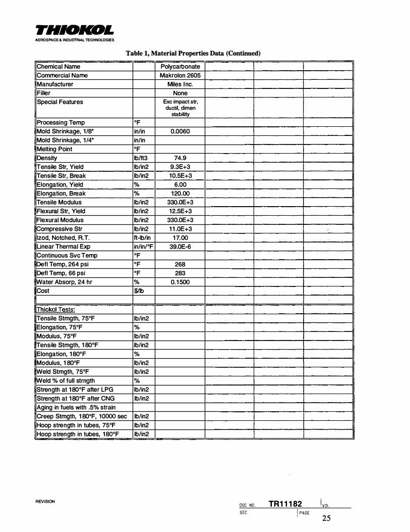
THIOKOL AEROSPACE & INDUSTRIAL TECHNOLOGIES
Table 1, Material Properties Data (Continued)
Chemical Name Polycarbonate
Commercial Name Makrolon 2605
Manufacturer Miles I nc.
Filler None
Special Features Exc impact str, ductil, dimen
stability
Processing Temp OF
Mold Shrinkage, 1/8" in/in 0.0060
Mold Shrinkage, 1 /4" in/in
Melting Point OF
Density lblft3 74.9
Tensile Str, Yield lb/in2 9.3E+3
Tensile Str, Break lb/in2 1 0.5E+3
Elongation, Yield % 6.00
Elongation, Break % 1 20.00
Tensile Modulus lb/in2 330.0E+3
Flexural Str, Yield lb/in2 12.5E+3
Flexural Modulus lb/in2 330.0E+3
Compressive Str lb/in2 1 1 .0E+3
lzod, Notched, R.T. ft-lb/in 1 7.00
Unear Thermai Exp in/in/°F 39.0E-6
Continuous Svc Temp OF
Defl Temp, 264 psi OF 268
Defl Temp, 66 psi OF 283
Water Absorp, 24 hr % 0.1 500
Cost $/Jb
Tensile Stmgth, 75°F lb/in2
Elongation, 75°F %
Modulus, 75°F lb/in2
Tensile Stmgth, 1 80°F lb/in2
Elongation, 1 80°F %
Modulus, 1 80°F lb/in2
Weld Stmgth, 75°F lb/in2
Weld % of full strngth 0/o Strength at 1 80°F after LPG lb/in2
Strength at 1 80°F after CNG lb/in2
Aging in fuels with .5% strain
Creep Stmgth, 1 80°F, 1 0000 sec lb/in2
Hoop strength in tubes, 75°F lb/in2
Hoop strength in tubes, 1 80°F lb/in2
REVISION DOC NO . TR11182 SEC
25 I PAGE

THIOKOL AEROSPACE & INDUSTRIAL TECHNOLOGIES
Table 2, Tube Burst Data
Thickness Burst average
Commercial Specimen 0.0. End A End S Temp. Pressure Strength & std dev.
Name Number (in) Max Min Max Min (OF) (psi) (psi) !(psi)
Vectra A950 A950 1 2.50 0.131 0.1 28 0210 0.204 70 862.40 8422 503€ Vectra A950 A950 2 2.50 0.131 0.1 29 0226 0205 70 555.99 5388 249� Vectra A950 A950 3 2.50 0.1 32 0.1 26 021 9 0205 70 342.13 3394 Vectra A950 A950 4 2.50 0.1 31 0.1 23 021 8 0202 70 289.52 2942 Vectra A950 A950 5 2.50 0.131 0.1 27 021 8 0204 1 80 995.55 9799 8531 Vectra A950 A950 6 2.50 0.131 0.127 0218 0204 180 641 28 6312 1761 Vectra A950 A950 7 2.50 0.131 0.1 27 0218 0204 180 804.35 791 7 Vectra A950 A950 8 2.50 0.131 0.1 27 0218 0204 180 1026.00 1 0098 Vectra A1 1 5 A1 15 39 2.50 0.128 0.12� 021 5 0204 70 1726.60 17405 1734€ Vectra A1 15 A1 1 5 40 2.50 0.126 0.1 23 0214 0204 70 1727.60 17557 2� Vectra A1 1 5 A1 1 5 1 1 2.50 0.127 0.124 0214 0204 70 1679.50 16930 Vectra A1 15 A1 15 12 2.50 0.128 0.1 24 0214 0.205 70 1735.30 17493 Vectra A1 1 5 A1 1 5 41 2.50 0.126 0.123 0214 0205 180 934.79 9500 917€ Vectra A1 1 5 A1 1 5 42 2.50 0.127 0.123 0214 0204 1 80 894.59 9091 241 Vectra A1 1 5 A1 15 9 2.50 0.1 27 0.1 24 0215 0205 180 912.61 9200 Vectra A1 1 5 A1 15 10 2.50 0.129 0.1 24 021 5 0205 1 80 884.01 891 1 Vectra A1 30 A130 2-a 2.12 0.141 0.1 19 0.179 0.1 35 70 510.48 4547 631� Vectra A1 30 A130 2-b 2.12 0.1 79 0.1 36 0206 0.1 48 70 928.68 7238 134:: Vectra A1 30 A130 7-8-a 2.1 2 0.1 32 0.123 0.162 0.144 70 696.38 6001 Vectra A1 30 A130 7-8-b 2.12 0.1 66 0.1 47 0.1 94 0.1 62 70 1035.70 7468 Vectra A1 30 A130 7-4-a 2.12 0.1 38 0.122 0.1 61 0.143 1 80 500.56 4349 455� Vectra A1 30 A130 7-4-b 2.12 0.167 0.1 47 0.1 92 0.1 62 1 80 673.75 4858 � Vectra A1 30 A130 7-10-a 2.12 0.131 0.124 0.1 61 0.1 43 1 80 486.41 4158 Vectra A1 30 A130 7·10-b 2.12 0.1 67 0.1 46 0.1 92 0.161 180 667.49 4846 AMODEL A-1 1 15 HS 1 1 1 5-1 2.50 0.132 0.123 0220 0214 70 61 1 .00 6209 781 5 AMODEL A-1 1 15 HS 1 1 1 5-6 2.50 0.133 0.1 26 0221 0.198 70 1331 .00 13204 4661 AMODEL A-1 1 15 HS 1 1 1 5-27 2.50 0.132 0.126 0223 021 1 70 734.00 7282 AMODEL A-1 1 15 HS 1 1 1 5-18 2.50 0.1 32 0.126 0223 0213 70 1 129.00 1 1200 AMODEL A-1 1 15 HS 1 1 1 5-15 2.50 0.142 0.1 28 0228 0219 70 123.00 1201 AMODEL A-1 133 HS 1 133-32 2.50 0.137 0.1 27 0228 0215 70 1 538.00 15138 1409� AMODEL A-1 133 HS 1 133-24 2.50 0.135 0.128 0220 0213 70 1728.00 16875 252� AMODEL A-1 133 HS 1 133-26 2.50 0.134 0.127 0226 0214 70 1 1 1 4.00 10965 AMODEL A-1 133 HS 1 1 33-29 2.50 0.1 34 0.126 0218 0213 70 1351 .00 1 3403 AMODEL A-1 145 HS 1 145-37 2.50 0.1 36 0.129 0221 0213 70 1329.00 12878 1 08 1 1 AMODEL A-1 145 HS 1 145-36 2.50 0.1 36 0.1 29 0220 0213 70 1 147.00 1 1 1 14 133€ AMODEL A-1 145 HS 1 145-2 2.50 0.1 33 0.126 0222 0213 70 931 .00 9236 AMODEL A-1 145 HS 1 145-3 2.50 0.1 32 0.125 0221 0213 70 1044.00 10440 AMODEL A-1 145 HS 1 145-4 2.50 0.1 34 0.126 0222 0216 70 1050.00 10417 RTP 4001 4001-4 2.50 0.131 0.126 021 8 0210 70 1032.00 10238 1 121( RTP 4001 4001-6 2.50 0.131 0.1 24 0220 0210 70 1014.00 10222 1034 RTP 4001 4001-42 2.50 0.135 0.1 27 021 6 0208 70 1167.00 1 1486 RTP 4001 4001-63 2.50 0.1 34 0.1 26 021 9 021 1 70 1 149.00 1 1399 RTP 4001 4001-64 2.50 0.1 33 0.127 0221 0210 70 1291 .00 12707 RTP 4005 4005-4005 2.50 0.1 36 0.127 0218 0208 70 1372.00 13504 15224 RTP 4005 4005- 2.50 0.1 33 0.126 0217 0204 70 1200.00 1 1905 2370 RTP 4005 4005-19 2.50 0.1 35 0.129 0226 0216 70 1736.00 16822 RTP 4005 4005-8 2.50 0.1 32 0.126 0219 0209 70 1704.0C 16905 RTP 4005 4005-3 2.50 0.1 36 0.1 29 0222 0213 70 1753.00 16986 Ryton Ryton 41 2.50 0.1 36 0.127 0224 0214 70 1666.00 16398 1 339 Ryton Ryton 37 2.50 0.120 0.1 1 0 0212 0200 70 1341 .00 15239 23013 Ryton Ryton 18 2.50 0.1 36 0.1 26 0227 021 3 70 1255.0C 12450 Ryton Ryton 9 2.50 0.1 34 0.�� 0225 0216 70 1 121 .00 1 1 033 Ryton Ryton 3 . 2.50 0.1 35 0.1 0225 0.216 70 121 2.0C 1 1836
REVISION DOC NO . TR11182 SEC I PAGE
26

THIOICOL AEROSPACE & INDUSTRIAl TECHNOLOGIES
Table 3, Tube Burst Summary
70°F 1 806F
Material Mean Std N Mean Std N (psi) Dev (psi) Dev
(psi) (psi)
Vectra A950 5036 2494 4 8531 1 767 4
Vectra A1 1 5 1 7346 284 4 9 1 76 247 4
Vectra A1 30 631 4 1 342 4 4553 354 4
AMODEL A-1 1 1 5 HS 781 9 4667 5 AMODEL A-1 1 33 HS 1 4095 2523 4 AMODEL A-1 1 45 HS 1 08 1 7 1 336 5 RTP 4001 1 12 1 0 1 034 5 RTP 4005 1 5224 2370 _§ Ryton 1 3391 2308
Table 4, Tank Dissect, RTP2399 x 68911A Polyurethane, Tensile Bars
75°F 1
Molded Bars 22,100 4,400 Dissected Tank
C tinder 2 1 ,400 1 1 ,500 Inner Web 6,000 2,500
Table 5, Tank Dissect, AMODEL A-1133 HS Polyphthalamide
75°F 1 80°F Tensile Flexure Tensile Flexure Strength Strength Strength Strength
(psi) (psi) (psi) (psi)
lded Bars 31 ,600 25,900
Dissected Tanks Cylinder Axial 23,800 42,300 22,000 41 ,800 Cylinder Hoo_p 10,700* 19,000 13,300* 25,300 Knit Line Axial 1 1 , 100 1 1,300 Knit Line Hoop 1 1 ,900* 21 ,100 1 1 ,100* 2 1 ,100 Web Transverse 14,700 12, 100
* Estimated from flexure strength
SEC I PAGE
l voL REVISION DOC NO . TR11182
27

THIOKOL AEROSPACE & INDUSTRIAL TECHNOLOGIES
Table 6, Tank Design Requirements
Condition Requirements Comments
Tank: Design
External Envelope
Subscale 12" X 10" X 6"
Full-Scale 36" X 24" X 14"
Internal Volume > 70% of external envelope
Fuel LPG
Loading
Service Pressure 250 psig Nominal internal pressure
Structural Factor 4.0 on ultimate Burst test verification of Safety 2.0 on yield
Dynamic Loads 30 mph vehicle crash
20 ft empty tank drop
Service Life
Tank: Life 15 years Includes 15,000 cycles to service pressure plus 3,000 to 1 .25 x service pressure
Environmental Conditions
Temperature -40°F to 1 80°F
Humidity 0% to 100%
Vehicle, road, and Salt spray "Identification of Service Environment of other fluids Engine oil NGV Fuel Cylinders", July 1994, Gas
Antifreeze Research Institute
Battery acid
Brake fluid
Propane and constituents
Other chemicals
Impact and Rock and gravel impact Pendulum impact and flaw tolerance tests Abrasion and scrapes
Safety
Fire No fragmentation of tank when subjected to fire or puncture
Puncture
SEC I PAGE
I VOL
REVISION DOC NO . TR11182
28
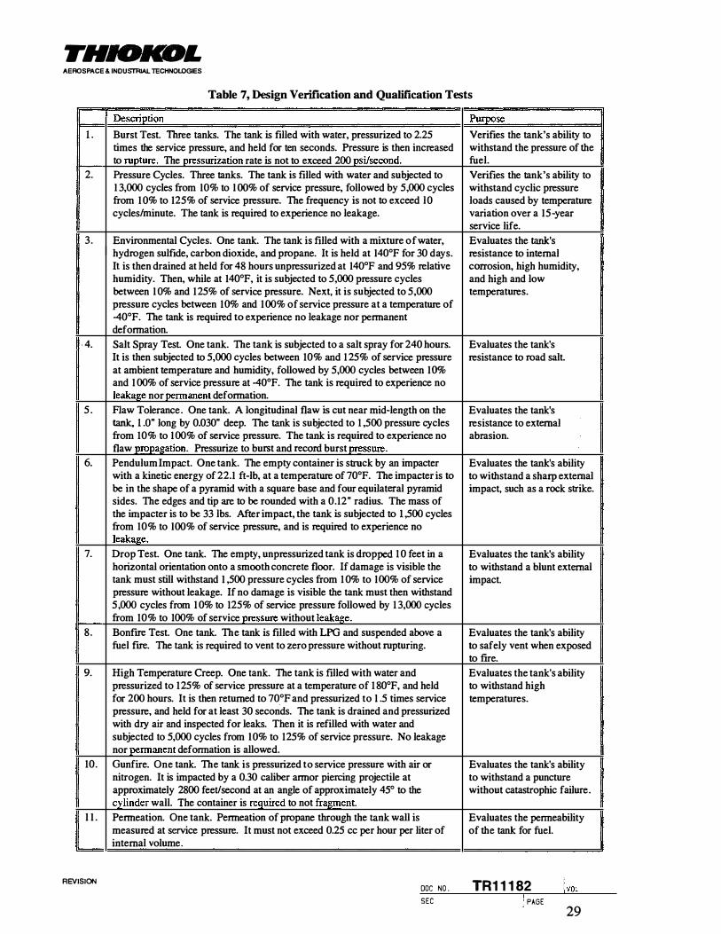
THIOICOL AEROSPACE & INDUSTRIAL lECHNOL.OGIES
Table 7, Design Verification and Qualification Tests
Description Purpose
l . Burst Test. Three tanks. The tank is filled with water, pressurized to 2.25 Verifies the tank's ability to times the service pressure, and held for ten seconds. Pressure is then increased withstand the pressure of the to rupture. The pressurization rate is not to exceed 200 psi/second. fuel.
2. Pressure Cycles. Three tanks. The tank is Itlled with water and subjected to Verifies the tank's ability to I 3,000 cycles from IO% to I OO% of service pressure, followed by 5,000 cycles withstand cyclic pressure from I O% to I25% of service pressure. The frequency is not to exceed lO loads caused by temperature cycles/minute. The tank is required to experience no leakage. variation over a I5-year
service life.
3. Environmental Cycles. One tank. The tank is Itlled with a mixture of water, Evaluates the tank's hydrogen sulfide, carbon dioxide, and propane. It is held at I40°F for 30 days. resistance to internal It is then drained at held for 48 hours unpressurized at I40°F and 95% relative corrosion, high humidity, humidity. Then, while at I40°F, it is subjected to 5,000 pressure cycles and high and low between I O% and 125% of service pressure. Next, it is subjected to 5,000 temperatures. pressure cycles between I 0% and I 00% of service pressure at a temperature of 40°F. The tank is required to experience no leakage nor permanent deformation.
- 4. Salt Spray Test. One tank. The tank is subjected to a salt spray for 240 hours. Evaluates the tank's It is then subjected to 5,000 cycles between 10% and 1 25% of service pressure resistance to road salt. at ambient temperature and humidity, followed by 5,000 cycles between I 0% and 1 00% of service pressure at 40°F. The tank is required to experience no leakage nor permanent deformation.
5 . Aaw Tolerance. One tank. A longitudinal flaw is cut near mid-length on the Evaluates the tank's tank. l .O" long by 0.030" deep. The tank is subjected to 1 ,500 pressure cycles resistance to external from 10% to I 00% of service pressure. The tank is required to experience no abrasion. flaw propagation. Pressurize to burst and record burst pressure.
6. Pendulum Impact. One tank. The empty container is struck by an impacter Evaluates the tank's ability with a kinetic energy of 22.I ft-lb, at a temperature of 70°F. The impacter is to to withstand a sharp external be in the shape of a pyramid with a square base and four equilateral pyramid impact, such as a rock strike. sides. The edges and tip are to be rounded with a 0.12" radius. The mass of the impacter is to be 33 lbs. After impact, the tank is subjected to 1 ,500 cycles from 10% to IOO% of service pressure, and is required to experience no leakage.
7. Drop Test. One tank. The empty, unpressurized tank is dropped 1 0 feet in a Evaluates the tank's ability horizontal orientation onto a smooth concrete floor. If damage is visible the to withstand a blunt external tank must still withstand I ,500 pressure cycles from 1 0% to I 00% of service impact. pressure without leakage. If no damage is visible the tank must then withstand 5,000 cycles from 1 0% to 125% of service pressure followed by 1 3,000 cycles from 10% to 100% of service _pressure without leakage.
8. Bonfire Test. One tank. The tank is filled with LPG and suspended above a Evaluates the tank's ability fuel fire. The tank is required to vent to zero pressure without rupturing. to safely vent when exposed
to flre.
9. High Temperature Creep. One tank. The tank is Itlled with water and Evaluates the tank's ability pressurized to 125% of service pressure at a temperature of 1 80°F, and held to withstand high for 200 hours. It is then returned to 70°F and pressurized to I .5 times service temperatures. pressure, and held for at least 30 seconds. The tank is drained and pressurized with dry air and inspected for leaks. Then it is refilled with water and subjected to 5,000 cycles from IO% to 125% of service pressure. No leakage nor permanent deformation is allowed.
10. Gunfire. One tank. The tank is pressurized to service pressure with air or Evaluates the tank's ability nitrogen. It is impacted by a 0.30 caliber armor piercing projectile at to withstand a puncture approximately 2800 feet/second at an angle of approximately 45° to the without catastrophic failure. cylinder wall. The container is required to not fragment.
I I . Permeation. One tank. Permeation of propane through the tank wall is Evaluates the permeability measured at service pressure. It must not exceed 0.25 cc per hour per liter of of the tank for fuel. internal volume.
!voL REVISION DOC NO . TR11182 SEC I PAGE
29

THIOKOL AEROSPACE & INDUSTRIAL TECHNOLOGIES
Table 8, Production Verification Tests
1 . Proof Test Every production tank will be pressurized to 150% of the service pressure and held for at least 30 seconds. Permanent volume expansion during this test is not to exceed 5% of the total expansion.
2. Leak Test Every production tank will be leak tested at service pressure with dry air. Weld seams and other joints will be examined for leakage.
3. Cyclic Pressure Test. One tank from each lot will be subjected to 5,000 cycles from 10% to 1 25% of service pressure, at a frequency not to exceed 1 0 cycles per minute. No leakage nor failure is allowed. The tank is to be destroyed after the test.
4. Burst Test. One tank from each lot will be subjected to a burst test. This may be the same tank that went through the cyclic pressure test. The tank will be pressurized to 2.25 times the service pressure, held for ten seconds, and then pressurized to failure. The pressurization rate is not to exceed 200 psi/second.
Table 9, Analysis Input Properties
Property J� Aluminum Steel
Modulus (psi) 1 .9E6 l .OE7 2.9E7
Poisson's ratio 0.41 0.3 0.3
Coeff. of Thermal Exp. (in/in/0F} 3.3E-5 1 .3E-5 6.5E-6
Mold shrinkage (in/in) 2.0E-3
lvoL REVISION DOC NO . TR11182 SEC I PAGE
30

THIOKOL AEROSPACE & INDUSTiliAL TECHNOLOGIES
Table 10, Finite Element Analysis Results, Original Subscale Design
Location Stress (psi) at Service Pressure of 250 psi
Shell Analysis Cylinder 4830 Web 4740 Small hole flange 3720 Large hole flange 3870 Dome 5696
Axisymmetric Analysis Around Boss 5325
Cross Section Analysis Cylinder 3843 Web 3750 Junction :fillet 5765
3-D Solid Analysis Cylinder 4515 Mid web 3900
Web between small hole and weblcyljunction 6477 Small hole flange 4874 Large hole flange 4242 Dome 5540
Table 11, Analysis Iterations for Second Subscale Design
Web Hole Stresses Model Cylinder Web Fillet Radius Y- z Y-joint Hole Hole Name Thickness Thickness Radius coord coord inner outer
edge edge sub2 solid 0.500 0.350 0.300 0.625 1 .600 3.800 7920 8940 9220 sub3 solid 0.500 0.450 0.400 0.625 1 .500 3.750 7920 8200 7340 !sub4 solid 0.500 0.450 0.500 0.625 1 .600 3.800 7980 7640 7670 subS solid 0.550 0.450 0.500 0.625 1 .500 3.750 7050 7620 7550 subS solid 0.550 0.500 0.500 0.500 1 .600 3.900 7250 7340 6750 fSUb7 solid 0.570 0.530 0.400 0.500 1 .600 3.900 7080 6930 6530
SEC I PAGE
I VOL
REVISION DOC NO . TR11182
31

THIOICOL AEROSPACE & INDUSTRIAL TECHNOLOGIES
REVISION
Material Properties Density (lblin3) Mtl Cost ($/lb) TO Tens Strenath (psi)
FD Rex Strength (psi)
FD Rex Modulus (psi)
FD Fail Strain (inlin)
Poisson's Ratio
Fabrication
Fab Cost ($/tank)
ReQuirements
Burst Pressure (psi)
Impact (in-lbs)
Design Geometry
Conformable?
Wh (in)
Wv (in)
L (in)
Nh (integer)
Nv (integer)
b/r (ratio)
Chlr (ratio)
Cv/r (ratio)
r (in)
Ch (in)
Cv (in)
ti (in)
ts (in)
tr (in)
th (in)
tv (in)
tO (in)
theta h (rad)
theta v (rad)
At (in2)
lAo (in2)
Sd (in2)
Vd (in3)
Vt (in3)
Vp (in3)
Vi (in3)
laallons (gal)
Veff (%)
weight (lbs)
material cost ($) total cost ($) V/$W (in3/$-lb)
Table 12, Cost Model for Aluminum Tank
6061 Alumin um
Full Size Confonnable Value Source or Description
lrm_uts
0.1 000
2.60
38000 38000
1 0.0E+6
0.0040
0.30
1 000.00 Estimate
1 000 4 x operatina pressure
Oloendulum impact
1 1=eonformable, O=cylinders
24.00 Tank Width
14.00 Tank Thickness
36.00 Tank Length
3 Number of cells across width 1 Number of cells through thickness
0.5000 Dome height/radius ratio
0.7143 Cell width/radius, optimize for max inside vol.
Calculations
- Cell thickness/radius
7.0000 Cell wall radius
5.0000 Cell width - Cell thickness
0.0000 thickness of outer wall for ductile impact
0.1 842 thickness of outer wall for strength
0.1842 thickness of outer wall - thickness of horizontal webs
0.1 31 6 thickness of vertical webs
0.3684 thickness of domes
-
1 2056
290.90 Total cross section area of tank profile
1 5.31 Cross section area of walls
n5.74 !Approximate surface area of domes
1 357.54 :Approximate volume of domes
9793.70 Total external volume of tank
Outouts
729.81 Total volume of tank walls and domes
9063.90 Internal volume
39.24 Internal volume
74.93% Volume efficiency
72.98 Empty tank weiaht
189.75
1 189.75
0.1 0439 Combined Performance
SEC I PAGE
l voL DOC NO . TR11182
32

THIOKOL AEROSPACE & INDUSTRIAL TECHNOLOGIES
Table 13, Cost Model for AMODEL AS-1133 HS Tank
AMODEL AS-1 1 33 HS
Full S ize Confonnable Value Source or Description
lrm_uts
Material Properties
Density (lblin3) 0.0528 Amoco
Mtl Cost ($Abl 2.85 Amoco
TO Tens Strength (psi) 7296 Tank Burst, 99% probability
FD Aex Strencrth (psi) 46000 Amoco
FD Aex Modulus (psi) 165000C Amoco
FD Fail Strain (in/in) 0.025C Amoco
Poisson's Ratio 0.41 Amoco Fabrication
Fab Cost ($/tank) 200.00 Estimate
Requirements
Burst Pressure (psi) 1 000 4 x operating pressure
Impact (in-lbsl 265 pendulum impact
Design Geometry
Conformable? 1 1=eonformable, O:::cylinders Wh (in) 24.00 Tank Width
Wv (in) 1 4.00 Tank Thickness
L (in) 36.00 Tank Length Nh (integer) 3 Number of cells across width
Nv (integer) 1 Number of cells through thickness b/r (ratio) 0.5000 Dome heiaht/radius ratio Ch/r (ratio) 0.7143 Cell width/radius, optimize for max inside vol.
Calculations
Cv/r (ratio) - Cell thickness/radius r (in) 7.0000 Cell wall radius Ch{in) 5.0000 Cell width Cv (in) - Cell thickness ti (hi) 02422 thickness of outer wall for brittle impact ts (in) 0.9594 thickness of outer wall for strencrth
tr (il}) 0.9594 thickness of outer wall
th (in) - thickness of horizontal webs
tv (in) 0.6853 thickness of vertical webs tO (in) 1 .9189 thickness of domes
theta h (rad) -
theta v (rad) 1 2056
At (in2) 290.90 Total cross section area of tank profile
lAD Cin2) 79.74 Cross section area of walls
Sd (in2) n5.74 Approximate surface area of domes
Vd (in3) 1 357.54 Approximate volume of domes
Vt (in3) 9793.70 Total external volume of tank Outputs
Vp (in3) 3801 .08 Total volume of tank walls and domes
Vi (in3) 5992.6:3 Internal volume
I Qallons (gal) 25.94 Internal volume
Veff (%) 49.54% Volume efficiency
weight (lbs) 200.70 Empty tank weight
material cost ($) 571 .99
total cost ($) n1 .99
V 1$W (in3/$-lb) 0.03868 Combined Performance
l voL REVISION DOC NO . TR11182 SEC I PAGE
33

FHIOKOL AEROSPACE & INDUSTRIAL TECHNOLOGIES
Table 14, Cost Model for FORTRON 0214 Cl Tank
FORTRON 021 4 C1 PPS
Full Size Conformable Value Source or Description
lnp_uts
Material Properties
Density (lblin3) 0.0488 Hoechst Celanese
Mtl Cost ($Jib) 5.65 Hoechst Celanese
TO Tens Stren!lth (psi) 12500 FD Tensile StmQth, Hoechst
FD Aex StrenQth (psi) 21000 Hoechst Celanese
FD Aex Modulus (psi) 600000 Hoechst Celanese
FD Fail Strain (in/in) 0.0400 Range .03-.06, Hoechst
Poisson's Ratio 0.41 Estimate
Fabrication
Fab Cost {$flank) 200.00 Estimate
Requirements
Burst Pressure (psi) 1000 4 x operatinQ pressure
Impact (in-lbs) 265 pendulum impact
Design Geometrv
Conformable? 1 1=eonformable, O=cylinders
Wh (in) 24.00 Tank Width
Wv (in) 14.00 Tank Thickness
L (in) 36.00 Tank len!lth
Nh (integer) 3 Number of cells across width
Nv (inteQer) 1 Number of cells throuQh thickness
blr (ratio) 0.5000 Dome height/radius ratio
Ch/r (ratio) 0.7143 Cell width/radius, optimize for max inside vol. Calculations
Cv/r (ratio) -- Cell thickness/radius r (in) 7.0000 Cell wall radius
Ch (in) 5.0000 Cell width
Cv (in) - Cell thickness
ti (in) 0.4443 thickness of outer wall for ductile impact
ts (in) 0.5600 thickness of outer wall for strength
tr (in) 0.5600 thickness of outer wall
th (in) - thickness of horizontal webs
tv (in) 0.4000 thickness of vertical webs
tO (in) 1 .1200 thickness of domes
theta h _(rad) -
theta v (rad) 1 2056
At (in2) 290.90 Total cross section area of tank profile
Ap (in2) 46.54 Cross section area of walls
Sd (in2) n5.74 App_roximate surface area of domes
Vd (in3) 1 357.54 Approximate volume of domes
Vt (in3) 9793.70 Total external volume of tank
Cutouts
Vp (in3) 2218.61 Total volume of tank walls and domes
Vi {in3) 7575.09 Internal volume
Qallons (Qal) 32.79 Internal volume
Veff (%) 62.62"/c, Volume efficiencv
weiQht (lbs) 10823 Empty tank weight
material cost ($) 61 1 .52
total cost ($) 81 1 .52
V /$W (in3/$-lb) 0.08624 Combined Performance
l voL REVISION DOC NO . TR1 1 1 82 SEC I PAGE
34

THIOKOL AEROSPACE & INDUSTRIAL TECHNOLOGIES
Table 15, Cost Model for Target Material
Target Material
Full Size Conformable Value Source or Description
lrm.uts
Material Properties Density (lb/in3) 0.0500 Mtl Cost ($11b) 6.00 TO Tens StrenQth (psi) 18000 FD Rex Strength (psi) 18000
FD Rex Modulus (psi) 500000 FD Fail Strain (in/in) 0.0600
Poisson's Ratio 0.41
Fabrication
Fab Cost ($/tank) 200.00 Estimate
Requirements
Burst Pressure (psi) 1 000 4 x operatinQ pressure
Impact (in-lbs) 265 I pendulum impact
Design GeometrY
Conformable? 1 1=eonformable, O=cylinders
Wh (in) 24.00 Tank Width Wv (in) 14.00 Tank Thickness L (in) 36.00 Tank lenQth
Nh (integer) 3 Number of cells .across width Nv (inteQer) 1 Number of cells th rouah thickness b/r (ratio) 0.5000 Dome height/radius ratio
Chlr (ratio) 0.7143 Cell width/radius, optimize for max inside vol. Calculations
Cv/r (ratio) - Cell thickness/radius r (in) 7.0000 Cell wall radius Ch (in) 5.0000 Cell width Cv_{in) - Cell thickness
ti (in) 0.3328 thickness of outer wall for ductile impact ts_(in) 0.3889 thickness of outer wall for strength tr (in) 0.3889 thickness of outer wall
th (in) - thickness of horizontal webs tv (in) 02778 thickness of vertical webs
tO (in) 0.7778 thickness of domes
theta h (rad) -
theta v (rad) 1 2056
At (in2) 290.90 Total cross section area of tank profile Ap (in2) 32.32 Cross section area of walls
Sd (in2) 775.74 Approximate surface area of domes Vd (in3) 1 357.54 Approximate volume of domes
Vt (in3) 9793.70 Total external volume of tank
Outouts
V�{in3) 1540.70 Total volume of tank walls and domes
Vi (in3) 8253.00 Internal volume
gallons (gal) 35.73 Internal volume
Veff (%) 68.23"/o Volume efficiency
weight (lbs) 77.04 Empty tank weight
material cost ($) 46221
total cost ($) 66221 V /$W (in3/$-lb) 0.16178 Combined Performance
S E C I PAGE
! voL REVISION DOC NO . TR11182
35

THIOKOL AEROSPACE & INDUSTRIAL TECHNOlpGIES
Table 16, Molding Results, Subscale Design 2
Serial Material Washed Cracked Cut Inserts Good Remarks Burst Failure Mode Number Pressure
(psi)
1 A I y A
2 A I A y possible hairline cracks � 188 leaked on weld; weld lonoitudinal split on side
3 A y A
4 A y A opened mold too early
5 A I,NCF y y A
6 A y A
7 A y A
8 A H,NCF A
9 A H,NCF y A fine cracks during wash
10 A y A
1 1 A y s 12 A y SA
13 A H SA y 430 broke in half at weld line
14 A H SA y 289 cracked and leaked at weld
1 5 F H y SA cracked through dome ovemiaht
1 6 F H y SA cracked during annealing
17 F H y SA
18 F H y SA cracked during annealing
1 9 F H,l y SA
20 F H SA y 643 fractured into numerous I pieces
21 F H SA y 839 fractured into numerous I pieces
Materials: A = AMODEL AS-1 133 HS F = FORTRON 021 4 C1
Washed: !=immersed H=hose, internal wash NCF=no cross flow
Inserts: A=aluminum S=Steel SA=sand filled aluminum
Table 17, Welded Bottle Burst Summary
70°F
Material Mean Std N
(psi) Dev
(psi)
RTP 4001 weld 3083.9 1 1 54.5 1 0
RTP 4005 weld 1 3829 755.61 2
AMODEL A-1 1 1 5 weld 7088.7 475.61 2
�ODEL A-1 1 33 weld 7339 614.69 2
l voL REVISION DOC NO . TR1 1 1 82 SEC I PAGE
36

THIOICOL AEROSPACE & INDUSTRIAL TECHNOLOGIES
Table 18, Tank Burst Tests, First Subscale Design
Tank Test Date Burst Notes 1 Number Pressure
4 27 March 1996 435 psi leakage around bosses 8 3 June 1996 =350 psi data acquisition problem
10 3 June 1996 464 psi higher injection rate & pressure 6 7 June 1996 459 psi cycled 15,000 times, 50-150 psi
Table 19, Impact Test Results
hnpact Tank Energy (ft-lb) Observed Damage Number Number hnpact Absorbed
I 1 3 10.2 5 . 1 pierced 2 3 5.0 none 3 3 7.5 6. 1 none 4 3 8.3 5 . 1 pierced 5 7 7.2 6.0 surface dent, interior cracks 6 7 7.0 4.9 interior cracks 7 7 6.3 4.3 interior cracks
I 8 7 5.3 4.3 interior cracks, possible damage from #7
Table 20, Target Properties for Material Development
Property C u rrent Ta rget
Stre n gth in 1 2 ksi >1 8 ksi
weak d i rection
Modulus 600 ksi >500 ks i
Stra i n 4.0% >6.0% M old S h ri n kage 1 .2% <0.5% Cost/pou n d $5.65 <$6.00
SEC I PAGE
lvoL REVISION DOC NO . TR1 1 1 82
37

THIOICOL AEROSPACE & INOUSTRIAL TECHNOLOGIES
25000
20000
0
:g =§ 0.9 � � ¢;; 0.8 "' "' o < �� 0.7
�.£ 0.6 .§ g n.s .::
1.0 1.5 2.0 2.S 3.0 3.5 4.0 4.5 5.0 Envelope Aspcet RJJtlo
!7 -.,; '· I � /�\.. ):') Y"-Y".r"� t, -'t .!\. A
Multiple Cylln.ders
Figure 1, The Conformable Storage Concept
0
���·· IQ·�----0 A-i 1 33
0 A-1 1 1 5
0 0 -"D .. ,
-�--------------��--:J
REVISION
=- 1 5000 rJj s rJj rJj Q) ,_
U5 1 0000
5000
0 1 0
(j v
0 (9· ----o
A1 1 33: stress = 26951 * timeA-. 03742 RA2 = . 864
A1 1 1 5 : stress = 1 6824 * timeA.. .02703 RA2 = .768
' ' ' !
1 00
. " ! 1 00 0 1 0000
Time (sec)
Figure 2, Creep Rupture at 180°F
DOC NO .
SEC
I ' ' J 1 00000 1 000000
TR11182 I vaL I PAGE

THIOICOL AEROSPACE & INDUSTRIAL TECHNOLOGIES
0.0014
0.0012
0.001
l: � 0.0008
� � 0.00)6 e ...
0.0004
0.0002
0
0
.E
l "'---------KJ
�.som_J 2 x 4 Cup, As Molded Tube Burst Test
Figure 3, Cup Mold and Tube Burst Test
� 1 1 I I I I I I I I I I I I I I I I I 1 I 1 I 1 I I I I I I I I I I I I I I I II II I /•\ I I J•• \ I I ..
· · · · ··... .1- "-. \ J 1 .. - -.. . . ' . I I
...:." ........
• • ..1 '\ -.: ......... �.· · - ' 1
••• -• -.__ '•.. • I , -..:-�---.;;;··-•• ,. � , , ,., ...... Jr.•' ·� ... ........ l
. :;.. • .. � -� .... · -�
--·' ·�' _ .... - ...... , . .... ::_�·,.:: .... __
2000 4000 6000 8000 10000 12000 14000 16000 18000 20000 Hoop SITenglll (psi)
Figure 4, Tube Burst Results
--vectra A950
- - - Vectra A 1 1 5
• • • · · · Vectra A130
-Amodei A-1 1 15 HS
- -Amodei A-1 133 HS
• • • Amodei A-1 145 HS
- - - - R1P 4001
- - - - R1P4005
- • Ryton
REVISION DOC NO. TR1 1 1 82 l voL SEC
39 I PAGE
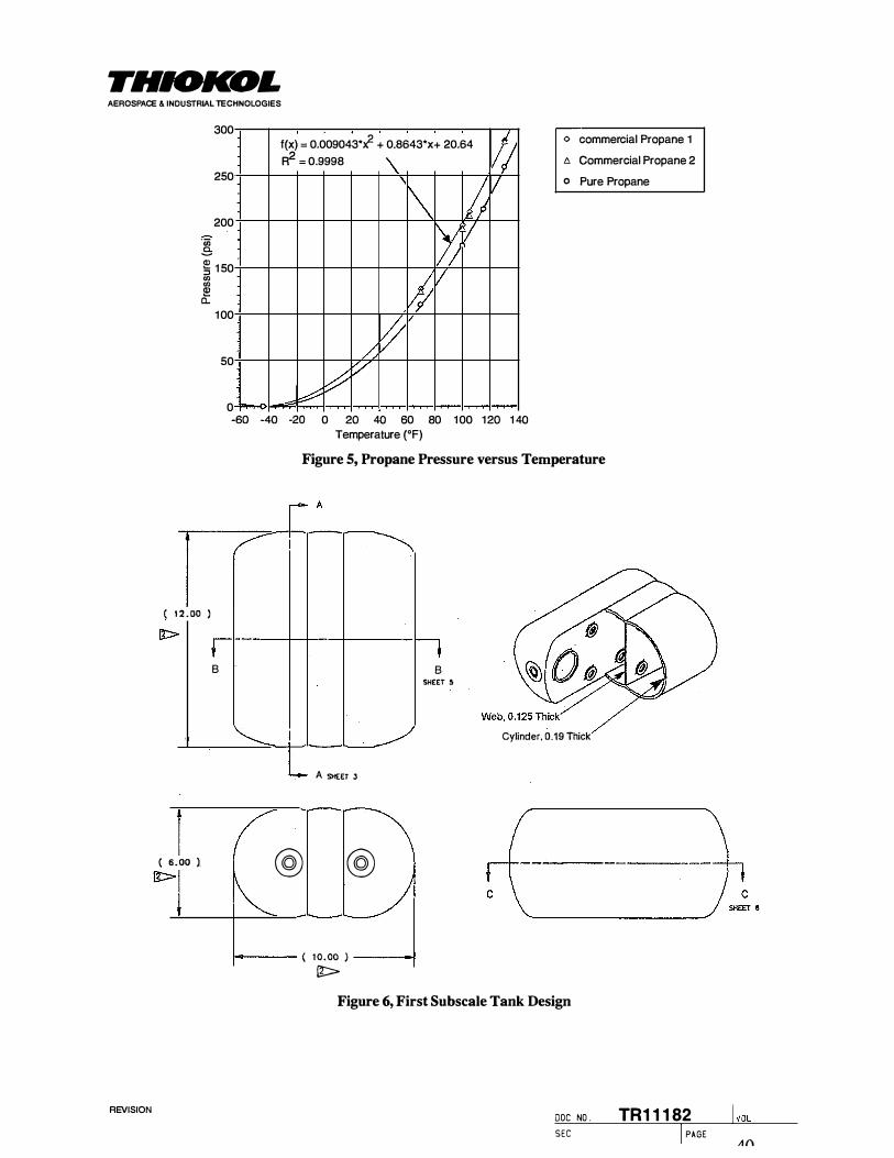
THIOICOL AEROSPACE & INDUSTRIAL TECHNOLOGIES
REVISION
·u; .e
300
250
200
� 1 50 en en !!:! a.
1 00
50
0
f(x) = 0.009043*; + 0.8643*x+ 20.64
R2 = 0.9998 \
1\ I� [>) v
I� v
� � � v
� ..,;:;
lij v
<> commercial Propane 1
c. Commercial Propane 2
o Pure Propane
� � � 0 � � 00 00 1 00 1 � 1 �
TT ( 1 2 . 0[) )
B
( 6 .00 ). �
Temperature ("F)
Figure 5, Propane Pressure versus Temperature
A
A SHEET 3
@ @
B SHEET �
Cylinder, 0.19 Thick
1-oo---- ( 1 0 . 00 ) -----l �
Figure 6, First Subscale Tank Design
DOC NO .
SEC
TR11182 I PAGE
l voL A f'l

THIOKOL AEROSPACE & INDUSTRIAL TECHNOLOGIES
Figure 7, Shell Element Model of First Subscale Tank
R
Figure 8, Axisymmetric Model of First Subscale Tank
REVISION DOC NO . TR1 1 1 82 SEC I PAGE
41

THIOICOL AEROSPACE & INDUSTRIAL TECHNOLOGIES
Figure 9, Cross Section Plane Strain Model of First Subscale Tank
Figure 10, 3-D Solid Element Model of First Subscale Tank
REVISION DOC NO . TR1 1 1 82 l voL S E C I PAGE
42

THIOKOL AEROSPACE & INDUSTRIAL TECHNOLOGIES
R.OIO R.005
1---- tllt .CHO ---1 1---- tiJ .380!:::':ll ---!
SECT I ON A-A
. 121 !.003 .6SO CI.AII! FOR 2-123 G-RING
Figure 11, Port Fitting Designed to Eliminate Leakage
Port Fitting
0-Ring
Tank Dome
Boss
Figure 12, Port Fitting Seals Against Plastic Face
REVISION DOC NO . TR1 1 1 82 SEC I PAGE
43
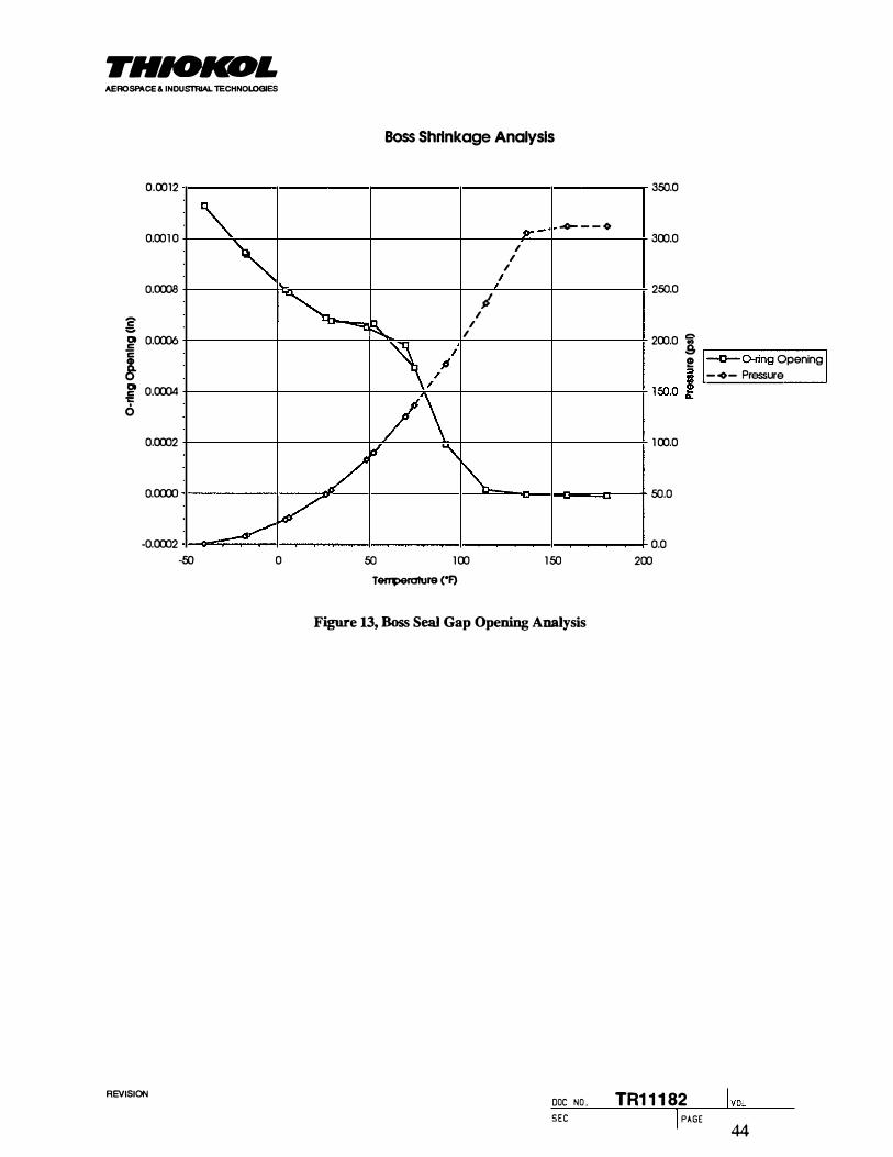
THIOICOL AEROSPACE & INDUSTRIAL lECHNOLOGIES
Boss Shrinkage Analysis
0.0012
0.001 0
0.0008
'C:' :;. Q 0.0006 .5 c
!Q 0.0004 c 'C 6
0.0002
0.0000
-0.0002
" /1'" --o- - - o
' /
/ /
/ ·� I
/ -c � /
/
'/ /\
_/ "' ""\
� �
/ -SO 0 50 1 00 1 50
T8fl'l)91'ature ("F)
Figure 13, Boss Seal Gap Opening Analysis
REVISION DOC NO .
SEC
350.0
300.0
250.0
200.0 � ,--------, ! -D--O-ring Opening i - �- Pressure
1 50.0 !
1 00.0
50.0
0.0 200
TR1 1 1 82 I PAGE
l voL 44

THIOICOL AEROSPACE & INDUSTRIAL TECHNOLOGIES
1 2 . 00
6 . 00 ( �-----' 1 0 . 00 =:J
Web , 0 . 25 t h i ck Cy l i nder . 0 . 30 th i ck
Ho l es t hrough ·webs
Figure 14, Intermediate Subscale Tank Design
REVISION
Q�r---------------------------------------1
0.0003
Q00025
}!;<
I 0.0002 }!;<
i Q00015 li:
0.0001
QOOOOS
i' Amodel Tank--../ �
Design 1 Streng1h ---..1 72()() psi I
J ' I \ I \ I \ I \ I \ I \ I \ I I
I I I I I I1 / .,
,
2000 oOXl 6000 8000 10000 12000 14000 16000 18000 20000 Hoop Slrlng!ll (pol)
Figure 15, Design Strength for Subscale Tank Design 2
DOC NO . TR1 1 1 82 SEC I PAGE
lvoL
45

THIOKOL AEROSPACE & INDUSTRIAL TECHNOLOGIES
Figure 16, Subscale Tank Design 2
REVISION DOC NO . TR1 1 1 82 l voL SEC I PAGE
46

r I
!
r
THIOKDL AEROSPACE & INDUSTRIAL TECHNOLOGIES
REVISION
STRESS STEP:a1 , !NC�1 , TIME•i .OOOOE+O
RESULTS : 2-STRESS STEP=! , ItiC=l , TI STRESS - MA>: PRIH MIH:-2. 12[+01 HAX : 7 . 08£+03 DEFORMATION: 1-D ISPLACEHEHTS STEP=l , IHC=1, TI DISPLACEMEI'IT - MAG M I H : 9 . 27E-04 MAX : 9 . 11£-0J FRAME OF REF: PART -=-:"'F'""h""'-
Figure 17, Stress Analysis for Design 2, Inside
STRESS RESULTS : 2-STRESS STEP=! , H'IC=l , TI STRESS - MAX PRIH H I H : - 2 . 12£+01 MAX: 7 . 08[+03 DEFORMAT ION: 1-DISPLACEMEHTS STEP=l ,IHC::::o1 , Tl DISPLACEMENT - MAG HIN : 9 . 27£-04 MAX : 9 . 11£-03
FRAME OF REF: PART
STEP"'! , I HC"'1 , TIME•i . OOOOE+O
Figure 18, Stress Analysis for Design 2, Outside
DOC NO . S E C
VALUE OPT IOH : ACTUAL
7 . 08[+03
7 . OOE+O
6 . OOE+O
5 . 00[+0
4 . OOE+O .
3 . 00[+0 .
2 .OOE+O 1
1 . 00[+0
0 .00[+0
-3 . 19[+0
\IALUE OPTIOH : ACTUAL
7 . 08[+03
7 .00[+0 .
6 . 00[+0
5 .OOE+O
2 .OOE+O
1 . 00[+0
O . ODE+O
-3 . 19[+0
TR 1 1 1 82 I PAGE
L17

'THIOICOL AEROSPACE & INDUSTRIAL lECHNOLOGIES
36 . 00
REVISION
Web . 0 . 60 t h i ck Cy l i nder . 0 . 69 t h i ck
Figure 19, Full Scale Tank Design
DOC NO .
SEC
TR1 1 1 82 I PAGE
48

THIOKOL AEROSPACE & INDUSTRIAL TECHNOLOGIES
Target Material
AMODEL AS·
1 133 HS
FORTAON 0214
C1 PPS
6061 Aluminum
0%
Target Material
AMODEL AS·
1 133 HS
FORTAON 0214
C1 PPS
6061 Aluminum
I
I I I I
20%
I
I I I I
I
I I
I I
I I
40% 60%
Volume Efficiency
I I I
I I I
I I I
I I I I I
J
I 80%
_L
Target Material
AMODEL AS-
1 133HS
FORTAON 0214
C1 PPS
6061 Aluminum
Target Material
AMODEL AS-
1 133 HS
FORTAON 0214
C1 PPS
6061 Aluminum
I
I I I I
0 50
t=J
--I
I
I 100 150 200
Weight
I I I I
I I 0 200 400 600 800 1000 1200 0.0000 0.0500 0.1000 0.1 500
REVISION
Tank Coot ($) Overall Grade: V/$W
Figure 20, Cost Model Comparisons
----�n�:..-_.;.o�- Bushing ·.>!fhl��FT- Nut
Figure 21, Original Injection Mold
DOC NO _ TR1 1 1 82 SEC I PAGE
250
I I :
; i ! \
0.2000
49
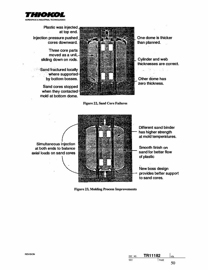
THIOKOL AEROSPACE & INDUSTRIAL TECHNOLOGIES
Plastic was injected at top end.
Injection pressure pushed cores downward.
Three core parts moved as a
sliding down on rods.
• . : ::.-'-Sand· fractured locally · . Y/here supported t>Y bQttom bosses.
Sand cores stopped when they contacted
mold at bottom dome.
Figure 22, Sand Core Failures
Figure 23, Molding Process Improvements
REVISION DOC NO .
SEC
One dome is thicker than planned.
Cylinder and web thicknesses are correct.
Other dome has zero thickness.
Different sand binder has higher strength at mold temperatures.
Smooth finish on sand for better flow of plastic
New boss design provides better support to sand cores.
TR1 1 1 82 I PAGE 50
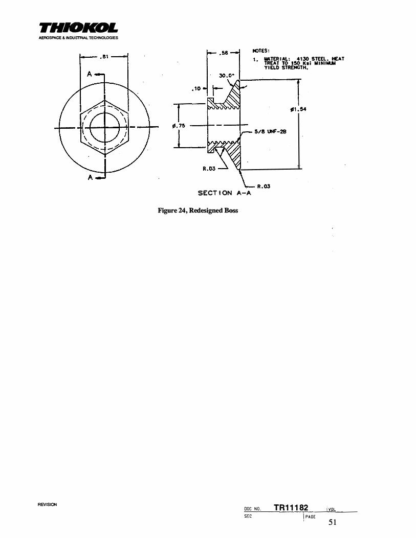
THIOKOL AEROSPACE & INDUSTRIAL TECHNOLOGIES
REVISION
SECT I ON A-A
Figure 24, Redesigned Boss
IMTER I Al. : 4130 STEEL . HEAT TREAT TO 150 K1i MINI ..... YIELD STRENGTH.
1 $/8 UNF'-28
R.Ol
DOC N O . TR1 1 1 82 SEC I PAGE 5 1

TI#IOKOL AEROSPACE & INDUSTRIAL 1ECHNOLOGIES
Figure 25, Injection Mold for Subscale Tank
SEC I PAGE
I VOL REVISION
DOC NO . TR1 1 1 82
'i?.

THIOKOL AEROSPACE & INDUSTRIAL TECHNOLOGIES
Figure 26, Sand Cores in Injection Mold
i I VOL
REVISION DOC NO . TR1 1 1 82 SEC I PAGE
:S l

THIOICOL AEROSPACE & INDUSTRIAL TECHNOLOGIES
Figure 27, Runner System for Balanced Injection at Both Ends
SEC I PAGE
I VOL REVISION
DOC NO . TR1 1 1 82
54

THIOICOL AEROSPACE & INDUSTRIAL TECHNOLOGIES
Figure 28, Mold Opened after Molding Part
REVISION
I PAGE
I I VOLDOC NO . TR1 1 1 82
55

THIOKOL AEROSPACE & INDUSTRIAL TECHNOLOGIES
Figure 29, Design 2, Tank #1, Dissected
REVISION DOC NO . TR1 1 1 82 SEC I PAGE
56

THIOKDL AEROSPACE & INDUSTRIAL TECHNOLOGIES
Figure 30, Design 2, Tank #20, After Burst Test
REVISION DOC N O . TR1 1 1 82 l voL SEC I PAGE
57

THIOICOL AEROS�CE & INDU�LTECHNO�ES
Hot Plate Weld
Figure 31, Welded Bottle Test
REVISION DOC N O . TR1 1 1 82 lvoL SEC 58 I PAGE

THIOICOL AEROSPACE & INDUSTRIAL TECHNOLOGIES
Welded Bottle vs Tube Bursts
0.0007T----------------------------------------------------,
0.0006
0.0005 I
I
:, I ': i I
1 0.0004
I 0.0003
�--Amodel A-1133 HS I - • · - Amodel A-1133 weld
REVISION
I
! I
0.0002 I
0.0001 ! i
/ 0 �--�--�--��--���----�--�--�----�--� 0 2000 4000 6000 8000 1 0000 1 2000 1 4000 1 6000 1 8000 20000
Hoop Strength (pal)
Figure 32, Weld Tests for AMODEL A-1133 HS
Welded Bottle vs Tube Bursts
0.0006 T-----------------------------------------------------,
0.0005
0.0004
:'. I ,I I l
I
I
j' 0.0003
J 0.0002
0 2000 4000 6000 8000 1 0000 12000 14000 1 6000 1 8000 20000 Hoop Strength (pal)
Figure 33, Weld Tests for RTP 4005
DOC NO . TR1 1 1 82 SEC I PAGE
lvoL 59

THIOKOL AEROSPACE & INDUSTRIAL TECHNOLOGIES
Figure 34, Design 1, Tank #10, After Burst Test
REVISION DOC NO . TR1 1 1 82 SEC I PAGE 60
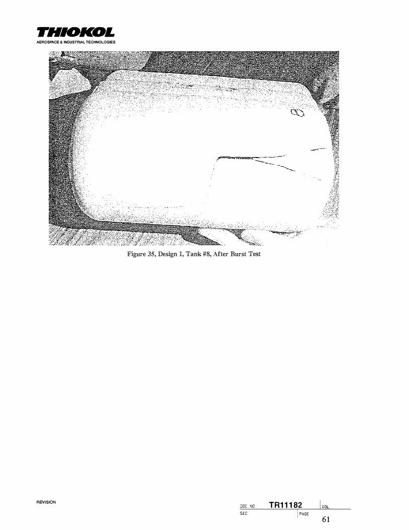
THIOICOL AEROSPACE & INDUSTRIAL TECHNOLOGIES
Figure 35, Design 1, Tank #8, After Burst Test
SEC I PAGE
l voL REVISION DOC NO . TR1 1 1 82
6 1

THIOKOL AEROSPACE & INDUSTRIAL TECHNOLOGIES
Figure 36, Design 2, Tank #21, Reassembled After Burst Test
I VOL REVISION
DOC NO . TR1 1 1 82 SEC I PAGE 62

THIOKOL AEROSPACE & INDUSTRIAL TECHNOLOGIES
Figure 37, Design 2, Tank #21, Weld Line Fracture
REVISION DOC NO . TR1 1 1 82 l voL SEC I PAGE 63

THIOKOL AEROSPACE & INDUSTRIAL TECHNOLOGIES
Figure 38, Design 2, Tank #20, After Burst Test
DOC N O . TR1 1 1 82 ! vaL REVISION
SEC I PAGE 64

THIOKDL AEROSPACE & INDUSTRIAL lECHNOLOGIES
REVISION
N I PPLES IN CELL L I NERS FOR CELL-CELL COitlMUN I CAT I ON
Figure 39, Design 2, Tank #21, Void Near Weld Line
OVERALL RE I NFORCEMNT: KN I TTED nJBE. ST I TCHED CLOSED AT ENDS
S I DE CELL RE I NFORCEMENT: KN i nED nJBE . T I ED CLOSED AT POLES
S I DE CELL L I NER : ROTOMOLOED THERMOPLAST I C
M I DOLE CELL RE I NFORCEMENT : KN I TTED nJBE, T I ED CLOSED AT POLES
M I DDLE CELL L I NER: ROTQI.AOLDED THERMOPLAS T I C
Figure 40, Design for SRIM Molding
DOC NO . TR1 1 1 82 SEC I PAGE
65
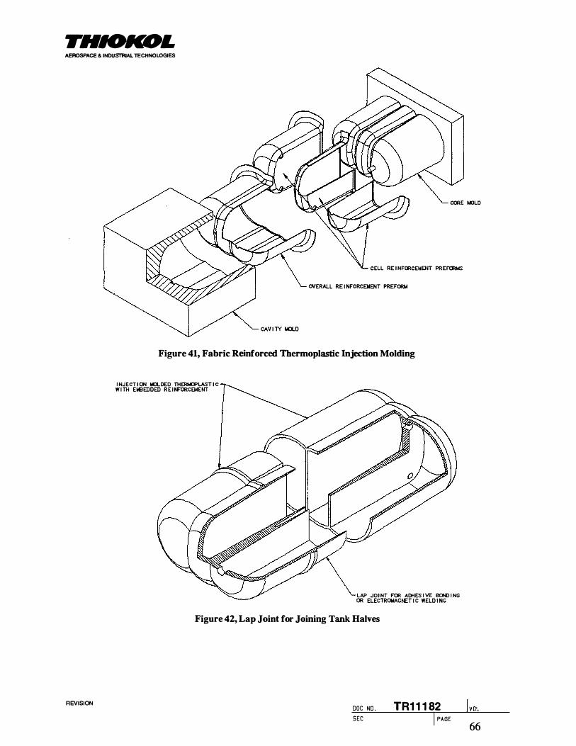
THIOICOL AEROSPACE & INDUSTRIAL TECHNOLOGIES
CORE t.IOLO
REVISION
CELL RE I NFCRCENENT PREF'CRMS
0/ERALL RE INFORCENENT PREFORM
CAV I TY t.o..D
Figure 41, Fabric Reinforced Thermoplastic Injection Molding
INJECT ION MOLDED TH�LASTIC W I TH Elai!EDDED REI �CEMENT
LA? JO I NT FOR ACHES I VE BCf,[) I NG OR ELECTROWACNET I C WELD I NG
Figure 42, Lap Joint for Joining Tank Halves
DOC NO . TR1 1 1 82 SEC I PAGE
l voL
66

THIOKOL AEROSPACE & INDUSTRIAL TECHNOLOGIES
I NJECT I 00 IO..DED THER!.ICPLAST I C W I TH EleEDDED R E I N'"CRCEMENT
LAP JO I NTS FOR ADHES I VE BOP{) I NG OR ELECTRQ.IA.CNET I C WELD II�
Figure 43, Double Lap Joint for Joining Tank Halves
REVISION
I NJECT I 00 Ia.. OED THER!.ICPLAST I C W I TH EtoeEDDED RE I N'"CRCEMENT
Figure 44, Butt Joint for Joining Tank Halves
DOC NO . TR1 1 1 82 SEC I PAGE
l voL 67

THIOICOL AEROSPACE & INDUSTRIAL TECHNOLOGIES
DISTRIBUTION
Recipient Mail Stop
Bob Graham 254
Rick Golde 230
Fred DuVall 230
Michael Blair 230
Richard Kunz 254
Mark Warner 254
David Son 254
George Berkley 252
NREL; Bill Warnock
NREL; Renee Howard
Brookhaven; Jim Wegrzyn
Hettinga; Siebolt Hettinga
REVISION DOC NO . TR1 1 182 SEC I PAGE
68

REPORT DOCUMENTATION PAGE Form Approved OMB NO. 0704-0188
,ublic reporting burden for this collection of information is estimated to average 1 hour per response, including the time for reviewing instructions, searching existing data sources, 3thering and maintaining the data needed, and completing and reviewing the collection of information. Send comments regarding this burden estimate or any other aspect of this
:bllection of information, including suggestions for reducing this burden, to Washington Headquarters Services, Directorate for lnforrc:ation Ope3�tions and Reports, 1215 Jefferson
)avis Hiqhwav. Suite 1204, Arlinoton, VA 22202-4302, and to the Office of Manaoement and Budoet. Paperwork Reduction Project 0704-0188 . Washinqton, DC 20503.
. AGENCY USE ONLY (Leave blank) 2. REPORT DATE 3. REPORT TYPE AND DATES COVERED
January 1 998 Subcontract report
L TITLE AND SUBTITLE 5. FUNDING NUMBERS
:>w-Cost Conformable Storage to Maximize Vehicle Range (C) YCF-5-1 4050-02 (T A) FU7021 30
' · AUTHOR(S)
P. Graham
PERFORMING ORGANIZATION NAME(S) AND ADDRESS(ES) 8. PERFORMING ORGANIZATION REPORT NUMBER
.1iokol Aerospace & I ndustrial Technologies '.0. Box 707 lriqham City, UT 84302-0707
j SPONSORING/MONITORING AGENCY NAME(S) AND ADDRESS(ES) 1 0. SPONSORING/MONITORING AGENCY REPORT NUMBER
lational Renewable Energy Laboratory '?17 Cole Boulevard NREUSR-540-23579 plden, CO 80401 -3393
1 . SUPPLEMENTARY NOTES l i
2a. DISTRIBUTION/AVAILABILITY STATEMENT 1 2b. DISTRIBUTION CODE
l ational Technical Information Service UC-1504 �.S. Department of Commerce �85 Port Royal Road .pringfield, VA 22161
3. ABSTRACT (Maximum 200 words) Although liquefied petroleum gas and compressed natural gas are attractive contenders for converting vehicles from gasoline andesel to alternative fuels, two factors inhibit conversion: additional vehicle costs and reduced range compared to gasoline. In overcoming these barriers, a key element f the alternative fuel system becomes the storage tank for these pressurized fuels. Thiokol Corporation has developed and is now producing a conformable aluminum torage system for liquefied petroleum gas, which increases the fuel storage in a given rectangular envelope. This project's goal was to develop the technology for a milar conformable tank made of injection-molded plastic to decrease costs.
L SUBJECT TERMS
lternative fuels, liquefied petroleum gas and compressed natural gas storage, pressurized fuel tanks
;
7. SECURITY CLASSIFICATION 1 8. SECURITY CLASSI FICATION 1 9. SECURITY CLASSIFICATION OF REPORT OF THIS PAGE OF ABSTRACT
)N 7540-01 -280-5500
1 5. NUMBER OF PAGES 70
1 6. PRICE CODE
20. LIMITATION OF ABSTRACT
Standard Form 298 (Rev. 2-89) Prescribed by ANSI Std. Z39- 1 8
298-1 02