chapter 8 miscellaneous construction€¦ · chapter 8 miscellaneous construction 8-01 erosion...
TRANSCRIPT

WSDOT Construction Manual M 41-01.36 Page 8-1 October 2019
Chapter 8 Miscellaneous Construction
8-01 Erosion Control and Water Pollution Control
GEN 8-01.1 Introduction
Federal, State, and local water quality regulations prohibit sediment and other pollutants associated with construction activity from impacting air and water quality. The requirements in this section exist to comply with these laws and the required Permits, and to prevent impacts to water quality. However, the scope and complexity of each project will affect what each project needs to do to manage these aspects of construction.
This section is predominantly written from the Transfer of Coverage (TOC) perspective because it is WSDOT’s standard practice for Design-Bid-Build (DBB) projects to transfer Construction Storrmwater General Permit (CSWGP) coverage to the Contractor the day after Contract execution. The TOC process helps ensure Contractors are invested in the Temporary Erosion and Sediment Control (TESC) planning, implementation and CSWGP compliance. In some cases, it may not be appropriate to transfer Permit coverage (e.g., Contracts with long winter shutdown or with multiple overlapping phases). Procedures vary for non-transfer DBB projects and Design-Build (DB) projects in which the Contractor obtains CSWGP coverage (see TESC Section 4-1.6.11 for more information). TOC is addressed in Division 8-01 of WSDOT’s Standard Specifications for Road, Bridge, and Municipal Construction (Standard Specifications), and additional TOC guidance is referenced in the TESC Manual and available on the Erosion Control Policies & Procedures webpage.
Once WSDOT transfers Permit coverage, the Contractor becomes responsible for all Permit requirements and WSDOT’s role becomes that of compliance assurance through Contract enforcement. Inspection of erosion control work is a specialized task and it is important that the Project Engineer allocate adequate Inspector resources and provide proper training for enforcement of the Contract Work. Internal training expectations can be found in TESC Section 1-1.2, and in 8-01.3.1.A of this chapter. A detailed list of inspection expectations can be found in TESC Section 4-1.
It is important for the Project Office to communicate early and often with regulatory agencies and other stakeholders. Establishing open communication early, prior to construction, sets up a good working relationship that may prove invaluable later in case problems occur during construction. Permits often require notification to regulatory agencies prior to conducting construction activities. The Project Engineer should consider inviting representatives from regulatory agencies to participate in the preconstruction conference to discuss environmental concerns.
The National Pollutant Discharge Elimination System (NPDES) Construction Stormwater General Permit (CSWGP) is one of the most common permits on our Contracts. While many of the requirements in this section exist to comply with CSWGP conditions, even if a Contract does not have a CSWGP, the Contractor is required to comply.

Page 8-2 WSDOT Construction Manual M 41-01.36 October 2019
Contracts not required to obtain Permit coverage must comply with all Federal, State, Tribal, or local laws, ordinances, and regulations that affect work in accordance with Standard Specifications Section 1-07.1. Washington State laws and regulations as codified in the Washington Administrative Code (WAC) and the Revised Code of Washington (RCW) provide specific requirements related to the protection of waters of the state (Chapter 173-201A WAC, Chapter 173-200, and Chapter 90.48 RCW).
This section of the Construction Manual does not replace the Temporary Erosion and Sediment Control (TESC) Manual. Inspectors that are tasked with TESC inspection should reference the TESC manual for in-depth guidance.
GEN 8-01.2 References
• Temporary Erosion and Sediment Control Manual
• Spill Prevention, Control, and Countermeasures Plan
• Erosion Control Policies and Procedures Webpage
• Department of Ecology Construction Stormwater General Permit
• Standard Specifications for Road, Bridge, and Municipal Construction
• RCW 90.48 – Water Pollution Control
• WAC 173-200 – Water Quality Standards for Groundwaters of the State
• WAC 173-201A – Water Quality Standards for Surface Waters of the State
• Standard Plans
GEN 8-01.3 Definitions
Best Management Practice (BMP) – means physical, structural, and/or managerial practices that, when used singularly or in combination, prevent or reduce pollutant discharges.
BMPs typically fall into three categories: design, structural, and procedural.
Design BMP – procedures or practices that minimize the erosion-related risk of a project, either during or after construction. Examples include projects that minimize the gradient and continuous lengths of temporary grade slopes or projects that phase work or save existing vegetation to minimize risk.
Structural BMP – devices that are installed in the field during construction. They may be designed to control erosion (source control) or sedimentation (treatment).
Procedural BMP – procedures or practices that minimize the erosion-related risk of a project, either during or after construction. For example, weekly site inspections and discharge sampling are important procedural BMPs that must be used to determine if site BMPs are functioning as needed or if they need to be maintained or enhanced.
Chapter 8 Miscellaneous Construction

WSDOT Construction Manual M 41-01.36 Page 8-3 October 2019
SS 8-01.3(1)A Submittals
TESC and SPCC Plans
The TESC Plan and the Spill Prevention, Control and Countermeasures (SPCC) Plan are used to manage erosion and spill-related risks during construction. Together, the TESC and SPCC plans are designed to meet the Stormwater Pollution Prevention Plan (SWPPP) requirements of the CSWGP, and ensure smaller Contracts that do not trigger the CSWGP do not violate water quality standards.
Projects Covered by a CSWGP
The Contractor is required to either adopt and modify the TESC Plan provided by WSDOT, or develop their own TESC Plan in accordance with the Temporary Erosion and Sediment
Control Manual (TESCM) – The Contractor’s TESC plan must be submitted as a Type 2 Working Drawing for review and comment in accordance with the Contract. The TESC Plan review checklist is available on the Erosion Control Policies and Procedures website and will be used by the Project Engineer when reviewing the TESC Plan.
Projects Not Covered by a CSWGP
WSDOT requires an abbreviated TESC plan for Contracts that disturb soil and have the potential to discharge waters of the state, but do not trigger CSWGP coverage. While Contract plan sheets are not required with an abbreviated TESC plan, they may help ensure the Contractor understands where BMP placement is needed to protect Waters of the State.
The Contractor is required to take measures to minimize discharges and prevent discharges wherever feasible. If discharges cannot be prevented, ensure they are managed to prevent impacts to Waters of the State and conduct monitoring. If evidence suggests a compliance issue (e.g. a turbidity plume, oil sheen) in the receiving water, the Contractor must initiate the Environmental Compliance Assurance Procedure (ECAP).
Miscellaneous Construction Chapter 8

Page 8-4 WSDOT Construction Manual M 41-01.36 October 2019
Qualified Personnel
Once the TESC Plan is ready for implementation, qualified personnel must be assigned to install, maintain, inspect, and test the system. The ESC Lead, Project Engineer, and Inspectors play crucial roles in the implementation of the plan and therefore must have the proper training and qualifications. Typically, the roles and responsibilities for erosion and sediment control are as follows:
ESC Lead
Responsibilities:
• attend the Pre-Construction Conference
• implement the TESC Plan including the installation and adaptive management of all BMPs
• maintenance of all BMPs
• develop and maintain a tracking table to show identified TESC compliance issues are fully resolved within 10 calendar days
• update the TESC Plan to reflect current field conditions
• sample and report water quality, as required
• develop and maintain the Site Log Book, as required
• perform and document site inspections of TESC BMPs
• be the primary point of contact on the Contractor’s Emergency Contact List for TESC-related issues
Training and Certification: The ESC Lead must have a current Certificate of Training in Construction Site Erosion and Sediment Control (CESCL) from a course approved by the Department of Ecology.
Project Engineer
Responsibilities:
• overall responsibility for enforcing the Contract
• delegate authority as appropriate
• ensure site inspections are occurring
• verify non-compliance events are escalated and reported
• ensure TESC Plans are maintained to reflect current field conditions
• confirm reporting and documentation requirements are met
• understand specific site requirements, including all Permits issued by regulatory agencies
If the Contractor fails to comply with the Contract requirements the Project Engineer may impose a suspension of work in accordance with Standard Specifications Section 1-08.6. The Project Engineer should also use the Prime Contractor Performance Report to encourage good behavior and reward excellent environmental compliance.
Chapter 8 Miscellaneous Construction

WSDOT Construction Manual M 41-01.36 Page 8-5 October 2019
Project Inspectors
Responsibilities:
• ensure BMPs are installed correctly
• verify DMR reporting is occurring monthly as required, and perform discharge compliance verification sampling if accuracy of data is in question
• verify the TESC Plan is reflective of current site conditions
• verify BMP maintenance and adaptive management
• communicate and work with the ESC Lead regarding deficiencies, or other matters as necessary
• escalate known deficiencies within Project Office structure
Training and Certification: The WSDOT Construction Site Erosion and Sediment Control Class offered through HQ Erosion Control Program is required every three years for Inspectors involved with the design, implementation, or verification inspection of TESC BMPs.
Implementation of the Plans
The Contractor must meet AKART (All Known, Available, and Reasonable methods of Prevention, Control and Treatment) as defined in WAC 173-218-030 prior to discharging from the construction site. To meet the AKART requirement the ESC Lead must select, install, maintain, and adaptively manage BMPs as required to ensure continued functional performance throughout construction. The ESC Lead documents this work in the TESC Plan.
Inspecting BMP installation is necessary to ensure proper methods and materials are used. Improperly installed BMPs will not be effective and can contribute to an erosion or non-compliance event. Some temporary products have materials requirements outlined in Standard Specifications Section 9-14.
If a Contractor wants to exceed the maximum acreage exposure limits allowed by Standard Specifications Section 8-01, they must request approval from the Project Engineer.
If the Project Engineer grants the Contractor’s request to exceed these limits, the Contractor must provide to the Project Engineer revised TESC and SPCC plans, commensurate with the scope and risk of the variance proposed, stating what measures will be used to protect the project site from erosion damage, how water quality and sensitive areas will be protected, and include the schedule of methods employed to regain adherence to Standard Specifications Section 8-01. The CSWGP prohibits the Project Engineer from increasing the time periods required in Standard Specifications Section 8-01 for covering erodible soil that is not being worked.
Miscellaneous Construction Chapter 8

Page 8-6 WSDOT Construction Manual M 41-01.36 October 2019
Adaptive Management and Feedback/Maintenance
The ESC Lead and Inspectors must inspect the area surrounding the installed BMPs to ensure they are installed and functioning properly, looking for signs of erosion, turbid water, or sheen. When BMP adaptive management is necessary, the ESC Lead must update a tracking table to show that identified TESC compliance issues are fully resolved within 10 calendar days after the issue was identified. The on-site TESC plan and SPCC plan must be updated with any changes including changes to BMP types and locations and changes to discharge points. These changes can be made by hand or electronically, as long as it can be accessed on-site. In all cases, the ESC Lead must document what adaptive management was done and include a completion date. If effective adaptive management is not feasible within 10 calendar days, Department of Ecology may approve additional time if the ESC Lead requests an extension within the initial 10 day timeframe.
As construction progresses, modifications of BMPs and the TESC Plan are necessary and required by the CSWGP to address changing site conditions. There are three common triggers to indicate when ESC Leads need to make these changes:
1. Visual monitoring or site inspection findings indicate BMPs are not performing as required. Under no circumstances should concentrated flow be allowed to develop. This type of flow can cause significant damage to the site as well as water pollution.
2. A change in work activity, site conditions, schedule, or design that impact erosion related risk(s).
3. A discharge sample over 25 NTU
SS 8-01.3(1)C Water Management
Several different permits can require water quality monitoring whether work is being done in the water or on land. Sampling frequency and location, compliance triggers, planning and reporting requirements vary depending on the type of Permit or certification issued.
For projects with a CSWGP:
The two most common measurements for pollutants are turbidity and pH:
1. Turbidity measures the clarity of water in nephelometric turbidity units (NTUs), most commonly using a turbidometer. The CSWGP establishes monitoring benchmarks between 25 to 250 NTU.
2. Water impacted by pH modifying sources must be characterized and, if authorized, must be neutralized prior to discharge to ensure it is within the range 6.5 to 8.5.
Projects that involve in-water work may be issued a Hydraulic Project Approval (HPA), a Letter of Verification (LOV), or a 401 Individual Water Quality Certification. Compliance for in-water work is evaluated differently than work covered by a CSWGP. In-water sampling (e.g., upstream and downstream) is different than discharge sampling for a CSWGP.
Chapter 8 Miscellaneous Construction
WSDOT Construction Manual M 41-01.36 Page 8-7 October 2019
The Permittee is required by law to report any water quality exceedance or Permit violation to the Department of Ecology. WSDOT has developed an internal ECAP, outlined in SS 1-07.5 of the Construction Manual that must be implemented immediately by the individual discovering the potential non-compliance event.
Documentation/Compliance/Reporting
Monthly reporting requirements begin as soon as the CSWGP is issued by Department of Ecology, even if construction has not yet started or a discharge has not occurred. Project Office staff are required to submit monthly Discharge Monitoring Reports (DMRs) until the CSWGP is transferred to the Contractor.
When WSDOT remains the Permittee, the Project Office is responsible for all Permit requirements including discharge sampling and the monthly DMR submittal to Department of Ecology’s WebDMR system. The Contractor will identify an ESC Lead to perform the Permit required site inspections.
Once ground disturbing construction begins, weekly site inspections and discharge sampling become required. Site inspections are required at a minimum weekly and within 24 hours of a runoff event.
Inspection and discharge sampling of temporarily stabilized, inactive sites may be reduced to once every calendar month with Project Engineer approval. The Project Engineer should consider the risks associated with less frequent inspections before approving reduction of inspections, including BMP failures, erosion potential, and seasonal factors.
Discharge monitoring must occur weekly and be scheduled around the weather, using a calibrated turbidometer (refer to TESC 4-1.3 for more details). Testing equipment must be onsite at all times, and must be calibrated per the manufacturer instructions. An updated calibration log must be maintained and stored with the equipment. The Inspector needs to be aware of benchmarks and when they are exceeded. The Contractor is required to document, adaptively manage, and report (if necessary) when this happens.
Documentation
The Site Log Book information may be kept electronically by the Permitee, but must be accessible on-site and must contain the following:
• Permit coverage issuance letter or completed Transfer of Coverage (TOC) form
• Updated TESC plan, SPCC plan, other related plans (e.g., chemical treatment plan)
• Discharge sampling data
• Site inspection reports
• Documentation of BMP adaptive management
• Contact information for onsite ESC Lead who perfom site inspections
• Other Permit related documents or approvals (e.g., sanitary sewer Permit, Administrative Order, approval for use of chemical treatment)
The Inspector should be checking the Site Log Book periodically to ensure it is kept up to date.
Miscellaneous Construction Chapter 8
Page 8-8 WSDOT Construction Manual M 41-01.36 October 2019
Environmental Compliance Assurance Procedure (ECAP) & Environmental Report Tracking System (ERTS)
Transparency with regulatory agencies when non-compliance occurs builds trust and sends a message that good faith efforts are made.
ESC Leads or other on site personnel must notify the Project Engineer immediately upon discovery of a water quality standard exceedance or other situation that may lead to a violation of the CSWGP by initiating ECAP. All effort will be made to cease the exceedance or rectify the non-compliance event before any work in or around the area resumes.
The ECAP is an internal procedure designed to escalate potential non-compliance issues. This may need to include notification of regulatory agencies, organization of cleanup activities, or further enforcement of the Contract up to or including suspension of part or all of the Work causing the non-compliance. WSDOT staff who observe a potential non-compliance event must submit specific information to their supervisor after the initial notification has been made. Refer to the procedure contained in SS 1-07.5 for more information on ECAP.
Initiating ECAP ensures that the non-compliance events are identified and fully addressed including preventing it from recurring. The Project Engineer and Regional Environmental Manager (REM) will work together on an appropriate response to the notification trigger. Minor non-compliance events that do not pose a threat to human health or the environment may be addressed and reconciled at the project level.
When the Permit has been transferred and the ECAP process is triggered, the Contractor shall fill out the ECAP Form (WSDOT form #422-011) and provide it to the Project Engineer within 48 hours of the non-compliance event.
In contrast to ECAP, Environmental Report Tracking System (ERTS) is a reporting system required by the CSWGP. While it is meant to escalate significant or severe non-compliance events similar to ECAP, ERTS is the notification system of the Department of Ecology. ERTS reports must be completed by the Permittee within 24 hours of a discharge of 250 NTUs or more or if non-compliance with WQS is confirmed. Department of Ecology must also be notified of events that pose a threat to human health or the environment. ECAP is initiated prior to submission of a report in ERTS. An ECAP report will usually have the same information required by ERTS.
SS 8-01.3G Completion/Close-out/Restoration
The CSWGP makes an important distinction between temporary and final stabilization. Termination of the Permit cannot occur until the project has reached final stabilization and the Contract work is physically complete. For final stabilization, all temporary BMPs must be removed unless approved by the Project Engineer to remain, and all exposed soil areas must be fully stabilized with permanent BMPs such as vegetation, rock, or equivalent permanent stabilization measures. Care must be taken to minimize soil disturbance upon removing temporary BMPs. Non-biodegradable BMPs must also be removed and soil must be permanently stabilize prior to submitting the Notice of
Chapter 8 Miscellaneous Construction

WSDOT Construction Manual M 41-01.36 Page 8-9 October 2019
Termination form. All Permit requirements must be performed until the CSWGP has been terminated.
Some projects may choose to leave sediment control BMPs such as silt fence in place until permanent vegetation has established, even if the duration extends beyond Contract completion. However, if the silt fence is left in place, the Permit cannot be terminated and all of the CSWGP requirements still apply, including the monthly reporting requirements. The Project Engineer may elect to coordinate with WSDOT Maintenance forces to arrange for silt fence or other BMP removal occurring after the Contract is completed.
Once Physical Completion has been granted the Contractor is required to submit a Notice of Termination (NOT) to the Project Engineer for review prior to submitting to Department of Ecology. Project Office staff must walk the site to ensure the NOT requirements have been met prior to NOT submittal. Once the Project Engineer confirms the requirements have been met, the Contractor must submit the NOT to Department of Ecology. If requirements have not been met, the NOT cannot be submitted to Department of Ecology. Prematurely submitting the NOT is a Permit violation. If the site has not achieved final stabilization, yet all other Contract work is complete, and the project is “waiting for grass to grow”, the Contractor may request to transfer the CSWGP back to WSDOT. If the CSWGP is transferred back to WSDOT (at the Project Engineers discretion), the Project Office becomes fully responsible for CSWGP compliance including site inspections, discharge sampling, and reporting until the CSWGP is terminated. To terminate the CSWGP after it is transferred back to WSDOT, the Project Office must submit the NOT to Department of Ecology.
Once a NOT is submitted, Department of Ecology may request a site visit or notify the Permittee that the termination request is denied. If no contact is made by Department of Ecology, the Permit is considered terminated the 31st calendar day after the date Department of Ecology received the NOT form.
Once the CSWGP is terminated, it should be “inactive” in Department of Ecology’s PARIS database. The Project Engineer should check the status of the Permit in PARIS to make sure it is “inactive”. If the Permit status is active in PARIS, monthly DMR requirements will continue to generate in WebDMR and the Permittee (WSDOT or the Contractor) may need to follow-up with the Department of Ecology Permit administrator to ensure the terminated Permits have been inactivated in PARIS.
SS 8-01.3(2)B Temporary Seeding
Temporary seeding is the establishment of a temporary vegetative cover on disturbed areas by seeding with an annual herbaceous plant (i.e. cover crop such as sterile wheat) which is quick to germinate than other species used for permanent establishment. Temporary seeding can stabilize disturbed areas that will be inactive for an extended period.
Miscellaneous Construction Chapter 8

Page 8-10 WSDOT Construction Manual M 41-01.36 October 2019
SS 8-01.3(2)D Temporary Mulching
Temporary mulching is a method of soil cover for temporary erosion prevention and control. It is also used to improve the soil environment for establishing vegetation. Organic mulches such as straw, wood fiber, chips, compost and bark are most effective for these purposes.
Both organic and synthetic tackifiers can be added to bind the mulch, seed, and fertilizer to the disturbed soil surface until vegetation is established. These tackifiers can reduce the displacement of soil particles, seeds, and mulch caused by wind or rainfall.
SS 8-01.3(3) Biodegradable Erosion Control Blanket
A In order to control the possible erosion resulting from fast runoff on steep slopes, biodegradable erosion control blankets are often used. Blankets also get used on flatter slopes where erodible soils are encountered. Using biodegradable erosion control blankets can provide a quick temporary protection until the grass has grown enough to be permanent protection for the soil, but the blanket cannot be expected to hold up to concentrated flows, so top of slope protections should be made to prevent such flows from developing and hitting the slope. Ditching, drains or dispersion BMPs such as compost socks should control drainage from above or beyond the raw slope. Every effort should be made to ensure that this kind of runoff is diverted away from the slope. In some cases, as determined by geotechnical analysis, permanent erosion control blankets or turf reinforcement mats (non-biodegradable) may be needed to stabilize a slope.
Emergency Projects
Department of Ecology uses the Federal expectations as outlined in the EPA’s Construction General Permit for emergency-related projects. Emergency projects require immediate authorization to avoid imminent endangerment to human health or the environment, public safety, or to reestablish public services. Such projects are authorized to discharge immediately on the condition that a complete and accurate NOI is submitted within 30 calendar days after commencing earth-disturbing activities. Department of Ecology’s Regional Permit Administrators should be contacted as soon as possible as their project specific expectations may vary. WSDOT’s emergency projects should operate as if covered under a CSWGP, including collecting discharge samples as soon as earth-disturbing work begins (document sample data onsite until a Permit is issued and data can be reported in WebDMR). While no TESC plan is required for emergency projects, these projects shall use the other site log book documentation requirements (e.g. record of implementation of Permit requirements such as the site inspections and adaptive management of BMPs) to meet the pollution prevention intent of a TESC plan.
Chapter 8 Miscellaneous Construction
WSDOT Construction Manual M 41-01.36 Page 8-11 October 2019
8-02 Roadside Restoration
GEN 8-02.1 General
The Roadside Policy Manual sets forth the following policy: The Washington State Department of Transportation (WSDOT) recognizes roadsides as an asset. WSDOT manages roadsides, balancing operational and environmental functions and lowest life cycle costs consistent with a reliable, safe, and sustainable transportation system. Roadsides are an important component of highway planning, design, operation, and maintenance because of the operational and environmental benefits the roadside provides. In reality, these functional benefits are interrelated and inseparable, and they affect the appearance of the roadside. Properly designed and maintained vegetation complements the functions of the roadway, integrates the roadway into the surrounding landscape, and has a positive effect on the traveling public. Roadside restoration is the process of replacing or rehabilitating functions lost through construction or other roadside disturbances.
According to RCW 47.40.010, the “planting and cultivating of any shrubs, trees, hedges or other domestic or native ornamental growth, the improvement of roadside facilities and view points, and the correction of unsightly conditions, upon the right-of-way of any state highway is hereby declared to be a proper state highway purpose.”
Proper implementation of this section is key in insuring the roadside features and functions are properly restored and continue to fulfill their intended purpose after the project is completed. It is understood that roadside restoration is often one of the last activities and it is for that reason that it is so important that inspections are timely and thorough.
This section is written to provide a unified source of information for project personnel engaged in construction phase roadside restoration activities. When questions of adequacy of roadside restoration materials and procedures are encountered, or when differences of opinion concerning the acceptance or rejection of materials occur and the answers are not readily found in this section, the Region Landscape Architect or HQ Landscape Architect should be consulted for assistance. In cases where insect damage and diseases are suspected, the services of an entomologist or plant pathologist may be required.
Ongoing coordination is needed between the Project Engineer, Inspectors, and Landscape Architects to assist in the successful completion of the project and a successful hand-off to Maintenance at the end of plant establishment.
GEN 8-02.2 Landscape Terminology
Acid Soil/Alkaline Soil – The acidity or alkalinity of a soil is measured in terms of its pH. Various plants respond differently to pH variations. Generally, the soil west of the Cascades is acidic, while east of the Cascades is more basic. The pH scale ranges from 0 to 14. A pH measurement of 7 indicates a neutral soil; a pH measurement below 7 indicates an acidic soil; and a pH measurement above 7 indicates an alkaline soil or basic soil. Generally, plants are selected for a particular area based on their ability to survive without a need to change the pH of the soil.
Miscellaneous Construction Chapter 8

Page 8-12 WSDOT Construction Manual M 41-01.36 October 2019
Balled and Burlapped (B&B) – Plants are prepared for transplanting by digging them so that the soil immediately around the larger, central roots remains undisturbed. The ball of earth and root is then bound in burlap or similar mesh fabrics. An acceptable B&B root ball should contain 90 percent (visual estimate of volume) of the earth material held together with root system when removed from the burlap. The soil must remain moist, but not fully saturated, before planting.
Bare Root (BR) – Most deciduous plants are dug when dormant. The roots are cleaned, pruned, and usually stored in moist material. Roots must remain moist and not allowed to dry out.
Botanical Name – The botanical, or scientific name is the plant name, written in Latin, which is used universally. The common name is the name used in a local area, and is not necessarily the same name used in other areas. The correct botanical name is usually found in “Standardized Plant Names” and is available from the Landscape Architect. The botanical name usually consists of two names, Genus and Species, but may include additional names.
Genus: 1st word Species: 2nd word Variety: 3rd word (if appropriate) Example: Sambucus racemosa melanocarpa Genus: Sambucus Species: Racemosa Variety: Melanocarpa
Branch – An offshoot from a trunk or main stem. It could be also called a bough or a portion of a main stem.
Bud – A small protuberance on a stem, branch, or cutting containing an undeveloped shoot, leaves or flowers.
Caliper – The diameter of the trunk of a deciduous tree is measured 6 inch above ground level, up to 4 inch caliper size. If greater caliper than 4 inch, it is measured at 4.5 feet above ground level. The measurement at 4.5 feet is commonly referred to as diameter at breast height (dbh).
Cambium – A thin layer of generative tissue lying between the bark and the wood of a stem, most active in woody plants. The cambium produces new layers of phloem on the outside and of xylem (wood) on the inside, thus increasing the diameter of the stem. Healthy cambium is green in color.
Cane – A primary stem which starts from the ground of a shrub or at a point not higher than ¼ the height of the plant. A cane generally only refers to growth on particular plant material, such as roses, etc.
Clumps – Plants with at least double the number of canes required for standard material; trees with three or more main stems starting from the ground. Vine maples are sometimes sold by the clump.
Chapter 8 Miscellaneous Construction
WSDOT Construction Manual M 41-01.36 Page 8-13 October 2019
Collected Material – Trees, shrubs, or other plant material collected from native stands, including Christmas tree stock and plants from native stands or forest plantings. After one growing season at the nursery, they are no longer considered collected material.
Compost – Stable, mature, decomposed organic solid waste that is the result of the accelerated aerobic biodegradation and stabilization under controlled conditions. The result has a uniform, dark, soil like appearance that smells like rich earth. Any ammonia smell indicates the compost is immature and a Solvita test should be run on the material.
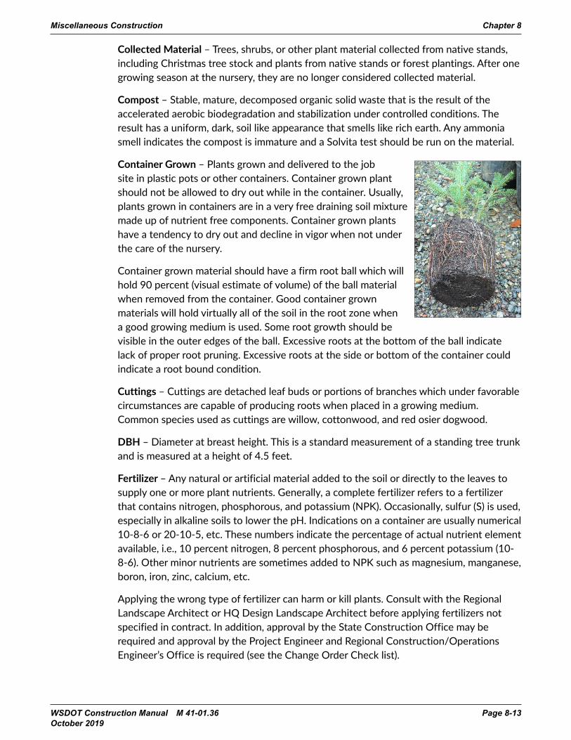
Container Grown – Plants grown and delivered to the job site in plastic pots or other containers. Container grown plant should not be allowed to dry out while in the container. Usually, plants grown in containers are in a very free draining soil mixture made up of nutrient free components. Container grown plants have a tendency to dry out and decline in vigor when not under the care of the nursery.
Container grown material should have a firm root ball which will hold 90 percent (visual estimate of volume) of the ball material when removed from the container. Good container grown materials will hold virtually all of the soil in the root zone when a good growing medium is used. Some root growth should be visible in the outer edges of the ball. Excessive roots at the bottom of the ball indicate lack of proper root pruning. Excessive roots at the side or bottom of the container could indicate a root bound condition.
Cuttings – Cuttings are detached leaf buds or portions of branches which under favorable circumstances are capable of producing roots when placed in a growing medium. Common species used as cuttings are willow, cottonwood, and red osier dogwood.
DBH – Diameter at breast height. This is a standard measurement of a standing tree trunk and is measured at a height of 4.5 feet.
Fertilizer – Any natural or artificial material added to the soil or directly to the leaves to supply one or more plant nutrients. Generally, a complete fertilizer refers to a fertilizer that contains nitrogen, phosphorous, and potassium (NPK). Occasionally, sulfur (S) is used, especially in alkaline soils to lower the pH. Indications on a container are usually numerical 10-8-6 or 20-10-5, etc. These numbers indicate the percentage of actual nutrient element available, i.e., 10 percent nitrogen, 8 percent phosphorous, and 6 percent potassium (10-8-6). Other minor nutrients are sometimes added to NPK such as magnesium, manganese, boron, iron, zinc, calcium, etc.
Applying the wrong type of fertilizer can harm or kill plants. Consult with the Regional Landscape Architect or HQ Design Landscape Architect before applying fertilizers not specified in contract. In addition, approval by the State Construction Office may be required and approval by the Project Engineer and Regional Construction/Operations Engineer’s Office is required (see the Change Order Check list).
Miscellaneous Construction Chapter 8

Page 8-14 WSDOT Construction Manual M 41-01.36 October 2019
Heeling In – A method of temporarily storing plants by covering roots with moist sawdust, mulch, soil, or a mixture of other materials capable of good moisture retention, to keep the roots from drying out.
Herbicide – A herbicide is a pesticide chemically formulated to control or destroy weeds. Herbicides are broken down into two main groups: Postemergence Herbicide and Preemergence Herbicide. Postemergence herbicide is a plant killing material that acts on the active growing surface of a plant after the plant has emerged from the soil. It is usually most effective during the rapid growth of the plant. Preemergence herbicide is a plant killing herbicide which acts to prevent the seeds, bulbs, tubers, stolons, etc., from sprouting (before-emergence).
Inoculated Seed – Seeds of the legume family that have been treated with nitrogen-fixing bacteria to enable them to make use of nitrogen from the soil atmosphere.
Mulch – Mulch is any loose material placed over soil, usually to retain moisture, reduce or prevent weed growth, insulate soil, or improve the general appearance of the plant bed. Additional fertilizer is sometimes necessary in order to offset the loss of plant nutrients used by the microorganisms that break down the mulch, especially when using non-native stock.
Mycorrhiza – A beneficial group of fibrous fungi that attach to the roots and absorb water and nutrients in solution and transfer this solution to the roots of plants. In effect, they multiply the plants’ root systems many times. These can be seen as fine white netting on moist compost or bark mulch. This is a good thing and not something to be concerned about.
Node – A small protuberance on a stem, branch or cutting containing an undeveloped shoot, leaves or flowers.
Pesticide – A pesticide is any substance or mixture of substances intended to control insects, rodents, fungi, weeds, or other forms of plants or animal life that are considered to be pests.
Root Ball – Ball of earth encompassing the roots of a plant. Generally, the root ball will have a good portion made up of root networks. A “manufactured-root ball” is one where the root system is not adequate to hold the soil in place. Manufactured root balls should not be accepted, since the root system is not developed sufficiently.
Rootbound (Pot Bound) – The condition of a potted or container plant whose roots have become densely matted and most often encircle the outer edges of the container. Generally, this condition is a result of holding the plant in the container for too long a period. Root bound plants should be rejected. See Standard Specifications Section 9-14.6(2). Circling roots will eventually kill the plant.
Chapter 8 Miscellaneous Construction

WSDOT Construction Manual M 41-01.36 Page 8-15 October 2019
Root Collar (Plant Crown) – Root Collar is the line of junction between the root of the plant and its stem, also known as the plant crown. The plant needs to be planted so the root collar is at or within an inch above the soil surface.
Runner – A long, slender, trailing stem that puts out roots along the ground. Where the nodes make contact with the ground, a new plant is produced. (For example: Kinnikinnick or wild strawberry.)
Soil Bioengineering – Soil bioengineering combines the use of live plants or cuttings, dead plant material, and inert structural members to produce living, functioning land stabilization systems.
Soil Amendment – A mixture of a growing medium, such as compost with the native top soil.
Vigorous – Plants that demonstrate vigorous growth have bright green cambium, strong stems and healthy leaves with no indication of stress (discoloration of leaves, insect damage, or wilt). Plants growing in a vigorous condition also have a well formed and healthy full crown with plump, firm and moist roots that have light growing tips during the growing season. A vigorous stand of grass has a lush, rich-green appearance with no dead patches or major gaps of growth within the established area. A stand of grass that displays rusting, wilting, stunted growth, diseased grass, or browning and yellowing of leaves is not considered vigorous.
Watering-in – Watering-in is a process used to settle the soil with water by eliminating air pockets during the planting process. This is also known as “puddling”.
WSNLA – Washington State Nursery and Landscape Association.
GEN 8-02.3 Reference Reading
Roadside restoration designs are in accordance with direction provided in the current version of WSDOT Roadside Policy Manual (RPM). Designers use guidance provided in the WSDOT Roadside Manual (RM), where appropriate, when implementing the provisions of the RPM. The RM addresses design issues such as law and policy, soil bioengineering, contour grading, vegetation, irrigation, etc. Another resource is the Inspection Guide for Landscape Planting published by AASHTO.
SS 8-02.2 Materials
Materials for roadside restoration include many items besides plant material, such as compost, topsoil, bark or wood chip mulch, soil amendment, pesticides, fertilizer, seed, hydromulch, staking and tying material, irrigation/electrical material (pipe, pumps, sprinklers, backflow control devices, valves, etc.). Drainage and surfacing materials are covered in their respective sections of the manual.
Miscellaneous Construction Chapter 8

Page 8-16 WSDOT Construction Manual M 41-01.36 October 2019
SS 8-02.3 Construction Requirements
SS 8-02.3(2) Work Plans
SS 8-02.3(2)A Roadside Work Plan
The Roadside Work Plan is a Type 2 Working Drawing that is required for all projects that disturb the roadside beyond 20 feet from the pavement or where trees or native vegetation will be removed. The Roadside Work Plan is intended to ensure that all impacts to the roadside vegetation and soils are minimized, preparatory activities are planned and coordinated with planting, and planting is coordinated with the removal of erosion control items.
The Roadside Work Plan is required to be submitted prior to performing work that disturbs the earth. Project Engineers should forward questions on Roadside Work Plans to the Region Landscape Architect or the HQ Design Landscape Architect.
The Contractor’s progress schedule should show the order in which the Contractor proposes to perform the roadside restoration work and it is expected that the Progress Schedule will be reviewed in conjunction with the Roadside Restoration Plan.
The Roadside Work plan must indicate the proposed timing to perform the work and must include the following activities:
Limiting Impacts to Roadsides
The Plan should show the limits of Work including locations of staging or parking. In the case of staging and parking areas, these areas could become compacted and the Plan may need to address protection and/or decompaction. The Plan should also indicate areas outside the clearing limits where vegetation must be removed for access or other reasons such as stockpiling of topsoil. Preservation and stockpile of topsoil or other native materials is expected for areas outside the clearing limits.
Roadside Restoration
The Plan must include a discussion of how and when the propagation and procurement of plants will occur. Contracts with large quantities of plants should show these activities in the Progress schedule. Delays have occurred due to unavailability of plants in the past.
Means and methods to limit soil compaction where seeding and planting are to occur, such as steel plates, hog fuel access roads, wood mats for sensitive areas (including removal) and decompaction for unavoidable impacts.
The Plan should indicate when erosion control items will be incorporated or removed.
Lawn Installation
The Plan should indicate the schedule for lawn installation work. It must also discuss the establishment and maintenance regimen for lawns.
Chapter 8 Miscellaneous Construction

WSDOT Construction Manual M 41-01.36 Page 8-17 October 2019
SS 8-02.3(2)B Weed and Pest Control Plan
This plan is required when the proposal contains the item “Weed and Pest Control,” and prior to application of any chemicals or weed control activities, the Contractor shall submit a Type 2 Working Drawing. The Weed and Pest Control Plan is intended to ensure that only approved pesticides are applied by licensed applicators. Only those pesticides listed in the table Herbicides Approved for Use on WSDOT Rights of Way and approved as part of the Weed and Pest Control Plan may be used. Refer to the website for the list of approved herbicides: www.wsdot.wa.gov/maintenance/roadside/herbicide_use.htm. The Contractor may request written authorization from the Engineer to use herbicides that are not on the list. In that case it is recommended that the Project Engineer consult with the Region or HQ Landscape Architect prior to approving the request. The Plan also requires SDS sheets are submitted in order to fulfill hazard communication. The Plan must include provisions to ensure worker safety until re-entry time periods have elapsed.
The Project Engineer should review the Working Drawing for completeness and consult with the Region or HQ Landscape Architect, as necessary.
SS 8-02.3(2)C Plant Establishment Plan
This Type 2 Working Drawing is required when the proposal contains the item “PSIPE__”, and must be completed prior to Initial Planting. The Plant Establishment Plan shall describe activities necessary to ensure continued health and vigor of planted and seeded areas in accordance with the requirements of Sections 8-02.3(12) and 8-02.3(13). Should the plan become unworkable at any time during the first-year plant establishment, the Contractor shall submit a revised plan prior to proceeding with further Work. The Plant Establishment Plan shall include:
1. Proposed scheduling of joint inspection meetings, activities, materials, equipment to be utilized for the first-year plant establishment. Section 8-02.3(13) requires the Contractor to meet monthly or at an agreed upon schedule with the Engineer for joint inspections. This plan should state when those inspections will occur.
2. Proposed adaptive management activities to ensure successful establishment of seeded, sodded, and planted areas. The plan should address when watering and fertilizer will be applied.
3. A contact person. This should be the person responsible for all plant establishment activities, including regular inspections and plant replacement.
4. Management of the irrigation system, when applicable. The plan should include provisions for regular inspection and winterization.
SS 8-02.3(3) Weed and Pest Control
Weed and Pest Control occurs in strategic areas and includes various methods. Product use, type and timing of application could affect target species control success. Improper weed and pest control application could damage desirable species to remain and cause inadvertent harm to people and the environment. The person applying the pesticides must be a licensed applicator and perform work according to Weed and Pest Control
Miscellaneous Construction Chapter 8

Page 8-18 WSDOT Construction Manual M 41-01.36 October 2019
Plan. The licensed applicator is responsible to only apply according to the label to ensure the proper material is used on the specific target, and with an appropriate timing of application. The pesticide label will give instructions such as intended use of the product, directions for use, and warnings. Ensure all chemical pesticides are delivered to the job site in the original containers or if pre-mixed off-site, obtain certification of the components and formulation from the supplier. The licensed applicator or operator shall complete WSDOT Form 540-509, Commercial Pesticide Application Record, each day the pesticide is applied and furnish a copy to the Project Engineer by the following business day. The Project Engineer is to distribute a copy of this record daily to the Region Operations or Maintenance Engineer and to the Roadside Maintenance Section at the HQ Maintenance and Operations Office in Olympia. Only herbicides listed at the Roadside Vegetation Management website shall be used.
Damage to adjacent areas, either on or off the Highway Right of Way, shall be repaired to the satisfaction of the Project Engineer or the property owner at no cost to the Contracting Agency.
SS 8-02.3(4) Topsoil
With increased focus on stormwater in Washington and new understanding of the role of soils in the mitigation of water quality and quantity, engineered soil and soil amendments have become an important stormwater Best Management Practice (BMP). Topsoil is a biologically active system of minerals, organic matter, air, water, and microorganisms that can take thousands of years to develop. Topsoil nourishes and provides structural support for plant roots and absorbs and cleans water. Most of our roadside projects strip away the desirable existing topsoil leaving behind a compacted layer unsuitable for plant growth. This requires the landscape architect to either amend existing soils or add suitable topsoil back on site.
Be aware that not all topsoils are created equal. SS 8-02.3(4) describes the main differences between Topsoil Type A, B and C.
Imported topsoil (Topsoil Type A) can be used to provide a medium for plant growth when native soil has been removed or is highly disturbed.
Remove, stockpile, and replace existing topsoil when appropriate. Existing topsoil can have necessary nutrients, organic matter, and microorganisms. The use of existing topsoil onsite (Topsoil Type B) can reduce the costs of disposing of excess excavated material. An examination of the site with an inventory of existing vegetation is necessary prior to determining when to use existing topsoil. Stockpiling of topsoil might not be advisable when noxious weeds and their seeds are present. Consult the Landscape Architect for assistance. Topsoil Type C is also existing naturally occurring native topsoil meeting the requirements of Topsoil Type B but obtained from a source provided by the Contractor outside of the Contracting Agency owned right of way. The Engineer needs to approve the material prior to removing from the proposed source.
Chapter 8 Miscellaneous Construction

WSDOT Construction Manual M 41-01.36 Page 8-19 October 2019
Ensure the project obtains the specified material to ensure not only healthy and viable plants, but to ensure topsoil quality and type that meets what the project bid and paid for. Certain topsoil can exceed heavy metals, chemicals or other soil properties detrimental to plant growth and sometimes harmful to humans and the environment. In this case, designers may require soil testing (to determine acceptable soils on our right of way) in addition to meeting the material standard requirements.
When provided in the Contract, topsoil should be evenly placed on the slopes at the specified depth for areas to be seeded. After placement of top soil, large clods, hard lumps, rocks 2 inches in diameter or larger, and litter shall be raked up, removed, and disposed of by the Contractor. Refer to Standard Specifications Section 8-02.3(4) for more information.
SS 8-02.3(5) Roadside Seeding, Lawn and Planting Area Preparation
Complete preparation steps prior to installation of plant materials according to the requirements of the Contract Plans and Specifications:
• Weeds are controlled throughout the entire planting and seeding areas, as called for by the Contract Specifications. Inspect weed root systems to ensure complete weed eradication. The interior color of dead or dying roots is usually tan or brown, whereas healthy roots are usually white. If the weed’s root systems are still alive, delay planting until they can be killed. Perennial weeds with extensive root systems such as Canada thistle, Japanese and Bohemian knotweed, horsetail, wild pea, field bindweed, and quack grass (see Common Weeds of the United States – United States Department of Agriculture) should only be controlled with herbicides by a licensed applicator, to avoid the spread of live plant parts that might produce further weed patches with manual removal.
• Areas to be seeded are to be prepared after final grading so that the soil surface is rough and loose, with ridges and furrows (narrow depressions) perpendicular to the slope or to the natural flow of water. This will slow the water velocity, increase water detention and infiltration, decrease runoff, and promote grass growth. This can be done through catwalking, the use of a cleated roller, crawler tractor, or similar equipment. Refer to Standard Specifications Section 8-01.3(2)A for more information.
• Seed and fertilizer are to be uniformly applied on the slopes at the rate and mixture specified in the Contract. Application shall be by hydro-seeder, blowing equipment, properly equipped helicopters, or power drawn drills or seeders. Where areas are inaccessible for this equipment, or when specified, approved hand seeding will be permitted.
• The Project Engineer should measure using the appropriate means to verify the acreage or square foot for seeding, fertilizing and mulching.
• During the seeding and fertilizing operation, the Inspector must verify that the material is placed at a uniform rate and compare the amount of seed and fertilizer applied, by counting the number of bags of material, with the area covered to verify that the proper rate of application is being placed.
Miscellaneous Construction Chapter 8

Page 8-20 WSDOT Construction Manual M 41-01.36 October 2019
• The seed and fertilizer may be applied in one application provided the seed and fertilizer are not mixed more than 1 hour prior to application. Mixing more than 1 hour prior to application will damage the seed. Otherwise, the seed shall be applied in a separate application prior to fertilizing and mulching. Lime, if specified should be applied separately from the seed and mulch.
• Planting holes, pockets, or beds are excavated to the required size and depth, and spaced as shown on plans.
• The backfill mixture is prepared and stockpiled according to Contract Specifications.
• The planting holes are excavated to the sizes indicated in the Contract Plans. The Standard Plans contain minimum planting hole diameters.
SS 8-02.3(6) Soil Amendments
The decision to use a soil amendment depends upon the existing soil and the desired outcome. Some soil amendments might encourage unwanted exotic vegetation, while the combination of other soil amendments with native soils might favor native vegetation.
Planting Media – Various additives are sometimes used to improve the root growing environment of the soil that exists on a site. Generally, soil amendment consists of compost. Additives may be either used as a blanket or incorporated into the existing soil. Check the planting (growing) media material against the specification.
SS 8-02.3(6)A Compost
Compost is used for multiple functions on projects. It serves as a soil amendment, may be a component of topsoil, and is used as an erosion control BMP when applied as a blanket over soil.
• Prior to placement review the compost for physical contaminants (plastics, concrete, ceramics, metal, etc.) and ammonia odor.
• The permanent protection of earth cut and fill slopes should be accomplished as soon as possible. When provided in the Contract, compost blanket should be evenly placed on the slopes to a depth specified, prior to seeding or other planting. The timing and scheduling of the compost application may occur as early as possible for erosion control purposes and not necessarily immediately prior to seeding and planting operations. If compost is applied days or weeks before seeding and mulching, or in arid and/or windy climates, the soil or compost needs to have a tackifier applied to prevent the compost from blowing away.
SS 8-02.3(6)B Fertilizers
Apply fertilizers in accordance with the Specifications. Cross check the label on the bag or container with the Specifications. When water soluble nitrogen fertilizers are used, particularly in lawn areas, adequate moisture is needed to prevent fertilizer burn of the grass.
Chapter 8 Miscellaneous Construction
WSDOT Construction Manual M 41-01.36 Page 8-21 October 2019
SS 8-02.3(7) Layout of Planting, Lawn and Seeding Areas
The layout of planting areas in wetlands or stormwater facilities is critically important to the wetland’s success. Many plants have exact water requirements and will not thrive or even survive if planted in water too deep or too shallow. Changed conditions happen frequently during the grading phase. Work with the Landscape Architect to ensure the hydrology of the grades are finished to the necessary elevations before planting. Close coordination with the designer during the grading and plant layout phases can identify potential problems and fix them before they become costly mistakes.
Tree locations might need to be adjusted to anticipate the size of the tree when fully grown for:
• Minimum clearance to roadways
• Mowing edge setbacks
• Sight lines
• Existing utilities
• Signs
• Structures
• Drains
Planting areas might also need to be adjusted to align with the plans and the disturbed areas, and the edge should create a “flowing” outline that is aesthetically pleasing and mowable. It is important that sufficient stakes are used to clearly outline the planting areas. Again, the Landscape Architect should be consulted to ensure proper planting area placement.
• Review the plan sheets, quantities, details, Specifications, and other provisions in the Contract with the Contractor. Questions or interpretations can be answered or problems resolved through discussion with the Region Landscape Architect.
• All materials that have Specification requirements shall have an approval of source prior to incorporation or use on the project. The Contractor is required to submit samples of materials to verify that the materials adhere to the specifications. See Chapter 9 for further instructions and Section 8-2.6 for examples.
• The Inspector should check and accept the stakeout of all planting areas and planting hole locations prior to excavation. Minor relocation of planting areas and holes can be done at this time to avoid utility lines, rock outcrops, drainage ditches, signs, obstructions, or impervious or wet soil conditions. If minor relocation of plantings is not possible, the Inspector should contact the Landscape Architect to adjust the design requirements or quantities.
SS 8-02.3(8) Planting
SS 8-02.3(8)A Dates and Conditions for Planting
Planting must be done during the planting windows, per the Standard Specifications to allow for maximum growth during the rainy season.
Miscellaneous Construction Chapter 8

Page 8-22 WSDOT Construction Manual M 41-01.36 October 2019
SS 8-02.3(8)B Plant Installation
Proper storage and handling of plant material is expected of the Contractor to ensure healthy plant material prior to planting.
Plant Material
Drying out, excessive heat and cold, and other environmental stresses can be extremely detrimental to a restoration effort. The planting plan was developed to respond to the contract impacts, but the quality and treatment of the materials on the site will be of the utmost importance to ensure success.
Inspection During Planting – Planting stock on hand and ready for planting at the construction site should have been inspected upon delivery, in accordance with the checklist under “Inspection at the Construction Site”.
Inspection at the Nursery – Upon Contractor request, inspections may be done at the nursery. However, acceptance is only given once on-site inspection determines the adequacy of the material to meet the specifications. The Region Landscape Architect or HQ Landscape Architect should perform this inspection and make recommendations to the PEO to be communicated to the Contractor.
Inspection at the nursery or other source of supply should include the following:
1. Review the general condition of the plant in the block from which the stock is to be taken:
a. Uniformity of Leaf Coloration – Yellowing or other leaf discoloration could indicate poor drainage, fertilizer deficiency, herbicide damage, insect damage, or disease, and may not meet specifications.
b. Bud Development – During dormant periods of the growth cycle, plants should have buds that are firm, moist, and uniformly spaced. A slight cut into the bark may be made to determine that the cambium, or growing layer just beneath the bark, is moist and green.
c. Uniformity of Growth – Acceptable plants in any given block should exhibit uniform vigor and health.
d. Spacing of Plants in the Nursery Row – Sufficient spacing is needed to permit vigorous development of the individual plant.
e. Soil – Plants to be balled and burlapped must be grown from soil that will hold a firm ball. Reject broken or loose balls due to the potential for damage to the hair roots.
f. Presence of Weeds – Reject containers with an abundance of weeds in the containers. An overgrown, weed-infested nursery block indicates lack of care and the plants growing in it may be in a poor state of vigor.
Chapter 8 Miscellaneous Construction

WSDOT Construction Manual M 41-01.36 Page 8-23 October 2019
2. Check individual plants for freedom from defects such as:
a. Decay – Reject trees with spots of decayed tissue on the trunk and branches.
b. Sunscald or Sunburn – Plants with damage to cambium tissue and bark due to sun scald on the south or southwest side are unacceptable due to the potential for secondary insect and/or disease infestation.
c. Abrasions of the Bark – Abrasions severe enough to damage the cambium tissue may be sufficient for rejection.
d. Girdling Roots – Roots that grow around another root or a stem are cause for rejection.
e. Improper Pruning – Pruning cuts should be made just outside the branch collar and close to the trunk or supporting branch. When a cut is made to encourage branching, it should be made back to a bud. Improperly pruned stubs that have died back are a significant point of entry for disease organisms.
f. Frost Cracks – Long vertical splits in the bark and/or wood may occur on the south and southwest sides of young and thin-barked trees. Such cracks may be invaded by canker or decay-producing fungi and bacteria.
g. Signs of Injury – Dead leaves, dry buds; dieback of twigs and branches; blackened sapwood and sudden, discolored patches of bark (sunscald) on the trunk or limbs.
h. Diseases – Look for abnormal growth of leaves, twigs, fruits, discoloration of leaves and bark, unusual discharges of sap through the bark, etc. Reject plants showing evidence of disease.
i. Insects – Look for insect eggs, spider webs, or evidence of damage from insect feeding on leaves, twigs, buds, or other plant parts. Examine the trunks of trees for borer holes which appear as tunnels drilled into the bark and inward into the wood of the trunk. Reject trees with evidence of borers or other insect damage. Often sawdust-like material can be found below bore holes.
3. Check individual plants for proper habit of growth as follows:
a. If a particular habit, i.e., single stem, multiple stem, has been specified, plants must conform to this requirement.
b. If no particular growth habit has been specified, then the current American Standard for Nursery Stock, Z60.1 as published by the American Association of Nurserymen should be used as a guide
c. Top growth on shade and flowering trees should be symmetrically balanced, have a single leader, and well-developed branching characteristic of the species.
d. Evergreen trees should be uniformly dense. Sheared plants, such as Douglas fir sheared for Christmas trees, are not allowed, unless specified.
e. Shrubs should be well branched in a manner characteristic of the species. If not specified in the contract, the standards for size and number of branches by species listed in the current American Standard for Nursery Stock, Z60.1 applies.
Miscellaneous Construction Chapter 8

Page 8-24 WSDOT Construction Manual M 41-01.36 October 2019
4. Remove a random sampling of plants from their containers to verify that the root system is healthy. Reject root-bound plants and plants that have insufficiently developed root systems to hold the soil together. Healthy roots will hold the soil mass together yet not be crowded around the outside perimeter of the container.
5. Tag planting stock meeting the above criteria with seals placed on all plants or representative samples at the nursery to assist in future inspection of these plants when delivered on the job site. Seals placed on planting stock for later identification do not imply acceptance on the construction site.
Inspection at the Construction Site – Acceptance of stock may only be given at the construction site according to the Standard Specifications. It ensures that the plants delivered are from an accepted source, are in a healthy and undamaged condition, and conform to sizes, quantities, and standards called for in the specifications. Plant inspection lots should be established and a representative number of plants should be inspected in accordance with Section 9-4.44.
Inspect the condition of the plant and verify that proper handling procedures have been followed from the time of initial inspection to delivery at the construction site. If there are questions about the following checklist, consult with the Landscape Architect for clarification.
Inspect plants delivered to the construction site for the following:
1. All planting stock are of the genus, species, variety, and sizes specified and conform to the contract specifications for the particular species, or variety, regarding straightness of trunk, branching structure, proportion, and size of material.
2. Individual plant measurements meet the contract specifications. If a particular detail of measurement has not been specified, the current edition of American Standard for Nursery Stock, Z60.1 shall be used.
3. Use judgment and selectivity to sample plant materials. Inspect the entire lot for the same criteria as in the nursery inspection. Ensure each shipment of plants is free of disease and insect pests, and meets all applicable State and Federal certification requirements. All necessary quarantine or State nursery inspection certificates accompany each shipment.
4. All trees and a representative sample of shrubs are legibly tagged with the correct botanical name, common name, and size to agree with the specifications and plant list. Bare-root plants have been shipped in bundles with each bundle properly tagged.
5. Inspect planting stock as the material is being unloaded, or immediately thereafter, so that plants that are obviously unacceptable can be set aside for removal from the project site.
a. It is sometimes helpful to mark the pots of unacceptable plants with a dot of spray paint to ensure they are set aside to return to the supplier.
b. Set plants in blocks of 10, 25, 50, or 100 containers for ease of counting plants – block size is dependent on the scale of the project.
Chapter 8 Miscellaneous Construction

WSDOT Construction Manual M 41-01.36 Page 8-25 October 2019
6. Large root stubs on nursery grown balled or bare-root stock are indicative of lack of proper care and root pruning, and sufficient grounds for rejection of such plants. Root stubs frequently characterize “collected” stock and precautions should be taken to ensure that root systems are adequate
7. Damage to plant material caused by improper operation of mechanical diggers may be sufficient cause for rejection at the construction site. Plants dug with equipment leave a cone-shaped ball; these should be carefully checked to make sure that an excessive portion of the root system has not been cut away. Feeder roots are the newly formed roots, usually white in color.
8. Bare Root Plants:
a. Where root formation is irregular on bare-root plants, measure the average spread of the roots, considering all sides of the plant, rather than the maximum root spread. The Inspector may allow moderate deviations (±10 percent) from exact measurements in the case of plants which normally have irregular root systems. Example: Vine Maple.
b. Bare root plants must be dormant when gathered and prepared for shipping. The normal test for dormancy is observation; if the plant has been subjected to cooling environment and the majority of the leaves have fallen naturally it is a good indication of dormancy. Expert advice from the Landscape Architect should be obtained in all other cases. Bare-rooted plants meeting the quality expectation have adequate live, damp, fibrous roots, free of rot and mold. Earth balls should be unbroken and of specified size.
c. Precautions should be taken to prevent the drying of root systems in all shipments of plants to ensure arrival in good condition. During transport, plants must have been protected by a covering such as canvas or plastic sheeting. Bare-root plants should have been protected by moist burlap, sawdust and surrounded by plastic, etc. Under no conditions should the roots system have been allowed to dry out. All plants must exhibit normal health and vigor.
d. Reject plants with roots that have dark brown tips, are shriveled, dried up, soft, slimy, smelly, or moldy.
e. Reject plants with dull green, streaked, or brown cambium. The inspector is authorized to examine cambium on randomly selected woody plants by removing a thin scraping of bark with a fingernail, small knife, or other tool.
f. Following completion of inspection, all plants accepted should be carefully stored as required below until planted.
9. Quality – The size and quality of planting stock are standardized as much as is practicable considering that the materials are live and may vary due to growing conditions. Judgment should be exercised and allowances made for reasonable variation in growth and appearance.
Miscellaneous Construction Chapter 8

Page 8-26 WSDOT Construction Manual M 41-01.36 October 2019
Interim Care of Planting Stock – Plants not planted on the day of arrival at the site should be stored and handled as follows:
• Outside storage should be shaded and protected from the wind.
• Plants stored on the project should be heeled-in to protect them from drying out at all times by covering the bare root or balls with moist sawdust, wood chips, shredded bark, peat moss, or other accepted mulching material. Plants, including those in containers, should be kept in a moist condition until planted by using a fine mist spray or soaker hose, instead of a heavy stream which may cause damage.
• Avoid damaging plants being moved from the storage area to the planting site. Balled and Burlapped (B&B) plants should be protected against drying and handled carefully to avoid cracking or breaking the earth ball. Plants should not be handled by the trunk or stems.
• Bare-root plants should be watered when removed from the heeling-in bed to protect the roots from drying and they must be planted quickly.
• Should damage occur, or be found at this time, the plants should be rejected and removed from the site.
• At the time of planting, the Inspector should be alert for any damaged soil balls, leaders, major branches, or roots. Pruning is permitted to remove minor damaged branches, if it will not affect the characteristic shape of the plant (see Western Garden Book – Pruning Techniques). All rejected plants should be replaced during the current planting season. All broken, torn, or damaged roots should be pruned, leaving a clean cut surface to help prevent rot and disease.
• In order to ensure against reuse of discarded plants, seals should be removed and the trunk or stems above the root crowns should be marked with a small spot of paint or dye. Since discarded plants are the property of the Contractor, they should not be marked or mistreated in such a way as to make them unfit for other uses.
Planting Operation – The Contract Specifications identify the work necessary to accomplish the planting. The following is a checklist of horticultural practices that may be used by the Inspector.
• Plantings should be performed only during the specified planting season according to the specifications.
• Check for proper positioning of the plants and the spread of the root system in the planting hole. For example, on live stakes, the buds must point up, see Standard Plan H-10-15-00.
• When laying out shrub and ground cover beds, define the perimeter by placing plants in a flowing line that clearly outlines the bed border. The interior should then be staked in accordance with the plant pattern and spacing.
• Before B&B plants are set into the planting hole, burlap, twine, and all other foreign materials shall be completely removed.
Chapter 8 Miscellaneous Construction
WSDOT Construction Manual M 41-01.36 Page 8-27 October 2019
• Check for correct depth of the root collar. Tree root collars should be above the soil but roots must be completely covered by soil. Occasionally, Contractors leave a portion of the rootball above the soil on the assumption that the mulch will cover it up. This is not an acceptable practice. Plants should not be planted deeper than the root collar – this is the point where the roots begin to spread from the trunk. In some cases, trees may have been planted too deeply at the nursery so make sure root collars are visible above the soil surface before planting.
• Before backfilling, especially in drilled holes, the sides and bottoms must be scratched and loosened to break all “glazing.” This promotes moisture transfer between different soils (existing and backfill).
• Place accepted backfill material around plant roots or plant balls, being careful not to damage the ball or the fine root system of bare-rooted plants. Do not allow backfill which is frozen or saturated.
• Eliminate air pockets in the backfill by filling, tamping, and watering. It is required in the Standard Specifications to water the plants thoroughly before the backfilling of the pit is completed. Container plants should be moist at the time of planting.
• When the above operations have been completed, unless otherwise specified, the Standard Plans planting detail H-10-10-00 requires a berm of soil to be formed from soil around the perimeter of the pit to form a basin or saucer to facilitate watering and retention of rain or irrigation water. When planting on slopes, the berm should be on the downhill side only. This allows the plant to catch runoff from up slope.
• Plants should be mulched to the specified depth with accepted mulch material. The Standard Plans require mulch to be feathered away from tree root collars. When mulching ground covers, ensure the plants are not buried in mulch.
• Excessive moisture in a planting area is defined as visible water in an area not designated as a wetland, and may require elimination or adjustment of planting in that area. Consult with the Region Landscape Architect when excessive moisture is encountered. Mounding may be considered when it is necessary to raise the bed above the water table. Planting in saturated soil often kills the plant because the water keeps oxygen from reaching the plant roots.
SS 8-02.3(8)C Pruning, Staking, Guying, and Wrapping
Plants should be wrapped and staked only if specified. Details for staking are shown in Standard Plan H-10-10-00.
• Trees normally should not be pruned except for broken branches, unless otherwise specified or directed.
• All staking and tying shall be removed at the end of the first year of plant establishment to prevent damage to the plant.
Miscellaneous Construction Chapter 8

Page 8-28 WSDOT Construction Manual M 41-01.36 October 2019
SS 8-02.3(9) Seeding, Fertilizing, and Mulching
Seed mixes are chosen specifically to meet different functions that include erosion and weed control, aesthetics, and permit obligations. Applying the incorrect seed mix to an area can lead to costly erosion and weed control problems.
• Collect seed labels from each bag and check them against the Specification.
• Verify all the applicable licenses, endorsements, and seed test certification from a certified seed testing laboratory as stated in the Specifications.
Seeding for permanent erosion control must be done during the seeding windows, per the Standard Specifications to allow for maximum germination and establishment during the rainy season.
Seed on soil is not considered adequate erosion control until a stabilizing cover of vegetation is established. For this reason, mulch is often applied with seeding to provide immediate coverage. Straw, wood strand mulch, and compost often get used with seeding application, as do a variety of hydraulically-applied erosion control products (HECPs).
West of the summit of the Cascade Mountain Range, HECPs may be applied with seed and fertilizer. Each pass must be applied from a different direction to get complete coverage of the soil.
East of the summit of the Cascade Mountain Range, the seed and fertilizer must be applied in a first pass. Short-term mulch may be added as a tracer. Consult with the Region Landscape Architect or the HQ Design Landscape Architect if assistance is needed.
Mulch is uniformly applied to the seeded areas within 48 hours after seeding. Straw mulch is to be applied with a forced air spreader. Straw mulch may not be practical in windy areas or in areas of concentrated flow. HECP is normally applied with a hydroseeder. Checks are necessary to determine that the mulch is applied uniformly and at the required rate. HECP should completely cover the ground surface with no gaps. In areas that cannot be reached by a mulch spreader, hand methods resulting in uniform application may be used.
SS 8-02.3(10) Lawn Installation
Lawn installation is not a typical restoration roadside practice but it may be required in more built or developed areas and be a result of project commitments. Refer to the Standard Specifications for dates and conditions for lawn installation and establishment.
SS 8-02.3(11) Mulch
Mulches can be used on the surface for temporary erosion prevention and control and incorporated into the soil to improve the soil environment for establishing vegetation. Organic mulches such as straw, wood fiber, chips, Compost Type 2, and bark are most effective for these purposes.
Chapter 8 Miscellaneous Construction

WSDOT Construction Manual M 41-01.36 Page 8-29 October 2019
SS 8-02.3(12) Completion of Initial Planting
The planting is complete when:
• 100 percent of plants are installed and watered-in. Watering is required by Standard Specifications Section 8-02.3(8) as a part of plant installation
• The planting areas are completely cleaned up.
• All repairs to irrigation systems have been completed, mulch is applied, and weeds are completely controlled.
SS 8-02.3(13) Plant Establishment
Plant establishment begins at Initial Planting Acceptance. The major items included in plant establishment are watering, weed control, litter pickup, start up and shut down of irrigation systems, and replanting. Weather and soil conditions dictate the need for watering. Over-watering is as harmful as under-watering. Plant establishment work is needed to ensure the survival and ongoing vigor of the plants.
Inspection During the Plant Establishment Period
Plants may be planted in any given area a considerable period of time prior to the granting of initial planting acceptance. During the interim between when plants are installed and initial planting acceptance the Contractor is responsible for the upkeep of planting areas and continued growth of plants.
Although planting stock has been properly selected, delivered to the planting site in a vigorous, healthy condition, and planted in accordance with good horticultural practices, survival and normal growth depend to a large degree upon appropriate care during the establishment period. A well rounded program of horticultural practices used during the establishment period may include watering, fertilizing, pruning, insect, disease, and weed control, and replacement of unsatisfactory plants in accordance with the specifications.
When plant establishment starts the area should be inspected to make sure that all plants are in place and healthy. Monthly inspections of the planting areas should take place with the Contractor on or near the first of each month during the Plant Establishment Period to spot any potential problems to which the Contractor needs to attend.
If differences of opinion concerning the need for a particular procedure occur, and the answers are not readily found in this guide, the Inspector should consult with the Region or HQ Landscape Architect.
The project Specifications should clearly indicate the length of the establishment period, which may vary from one area of the state to another, depending on the local conditions, project commitments, climate, and the type of plant materials utilized. A minimum of three years of plant establishment work is required for all planted areas in western Washington, and planted and/or seeded areas in eastern Washington. The default period for plant establishment performed by the Contractor in the Standard Specifications is a minimum of one year. Subsequent years will be funded from Capital Program Development & Management through environmental mitigation and roadside restoration funding. Work will be managed by WSDOT.
Miscellaneous Construction Chapter 8

Page 8-30 WSDOT Construction Manual M 41-01.36 October 2019
A. Inspection Checklist – The following inspection checklist includes the primary items which should be observed periodically during establishment.
• The project areas are weeded.
• Plants that have sagged, fallen over, or are otherwise not situated in a natural growing position, as appropriate for the species, may require repositioning.
• Firmly embed stakes or reinstall as necessary.
• Protect the root mass to avoid disturbance to the root mass. Replace topsoil as required if soil has subsided.
• Staked trees are straight. Adjustment of stakes may be needed. Where used, protective wrapping on trunks or stems is secure.
• Damage due to vandalism, vehicles, or fire is noted and corrective action taken.
• Record damage caused by animals (i.e., deer, rodents) and seek advice on protective measures.
• Report infestations of insects and disease to the Landscape Architect for corrective action.
• Broken branches have been pruned just above the break.
• Where discoloration of foliage occurs, especially in evergreen material, seek advice on corrective measures. Once evergreen foliage is brown recovery is not possible.
• Dead and severely damaged plants are removed immediately and replaced during the next appropriate planting period.
• Mulch is to the correct overall depth. Add or replace as required.
• Berms and water basins (constructed for the purpose of retaining water) are functioning properly. Repair and rebuild as necessary.
• If natural rainfall during the establishment period is insufficient for normal plant growth, supplemental water has been supplied.
• Supplemental fertilizers have been applied if required by the Contract Specification.
B. Inspection at the End of the Plant Establishment Period – Conduct a plans-in-hand review of each planting area or bed to determine that the arrangement, number, and species of healthy plants called for on the Planting Plans are present.
This inspection is of major importance to the ultimate success of the project; include a Landscape Architect, the Inspector, and Contractor on the inspection team.
Remove all plants rejected during the inspection and replace with new plants that meet all of the requirements of the contract and the Standard Specifications.
The final acceptance of the project is not complete until all plant establishment requirements have been satisfactorily made.
SS 8-02.3(14) Plant Replacement
Inspect and approve all replacement plant material prior to installation.
Chapter 8 Miscellaneous Construction

WSDOT Construction Manual M 41-01.36 Page 8-31 October 2019
SS 8-02.3(15) Bioengineering
Soil bioengineering is the use of plant material, living or dead, to alleviate environmental problems such as shallow rapid landslides, and eroding slopes and streambanks. In bioengineering systems, plants are an important structural component, not just an aesthetic component. Soil bioengineering may be used as a BMP to stabilize and revegetate slopes and stream banks when changes in condition require adaptation to control sediment and erosion. For more information on the uses of soil bioengineering, see the Roadside Manual M 25-30 Chapter 740, and the Roadside and Site Development website.
SS 8-02.3(16) Roadside Maintenance Under Construction
For larger construction projects that span multiple seasons, certain areas of the roadside will require additional work when WSDOT maintenance crews have no access within project limits. Expectations for roadside mowing and ditch maintenance are outlined in the Standard Specifications if the item “Roadside Maintenance Under Construction” is included in the Contract.
SS 8-02.5 Payment
The Project Engineer shall make an inspection of the planting areas before payment is made, to determine if the required work has been accomplished and the number and species of plants shown on the Planting Plans are in a healthy condition. No payments shall be made for plants that are not in a healthy condition, although partial payment may have been made following a previous inspection.
8-03 Irrigation System
GEN 8-03.1 General
The objective of irrigation on WSDOT contracts is to help ensure plant survival by supplementing natural precipitation during dry periods. This can often be accomplished with far less water than that required to obtain maximum growth and yields. Application rates of irrigation systems are, therefore, designed from the standpoint of minimum moisture requirements of the plants.
A properly designed and installed irrigation system will distribute water uniformly over the intended planting area at a predetermined precipitation rate, or by irrigating within the root zone of plants by bubblers or a drip system. Many factors influence the efficiency of a system’s operation and must be taken into consideration during the design stage. In addition, care must be taken when inspecting installation of the irrigation system to ensure that the system not only follows the designer’s intent, but also fully conforms to the Standard Specifications, project plans and provisions, and the manufacturer’s requirements and recommendations.
The most efficient and economical irrigation design is only as good as its installation, and this depends upon careful and thorough inspections.
Miscellaneous Construction Chapter 8
Page 8-32 WSDOT Construction Manual M 41-01.36 October 2019
GEN 8-03.2 Inspection
Thorough inspections, carefully conducted during construction, are of utmost importance to help ensure proper installation. To be adequately prepared for inspecting the installation of irrigation systems, it is of great benefit for the Inspector to have previous knowledge, preferably some experience, in at least one of the various aspects of irrigation design, installation, and maintenance. This not always being possible, it becomes necessary for the Inspector to first familiarize themselves with those portions Standard Specifications Sections 8-03 and 9-15 and contract documents that pertain to inspection and irrigation systems before attempting the necessary inspections. In addition, since irrigation inspection requires such varied and versatile knowledge and experience, it is advisable for the Inspector to obtain additional advice and/or assistance from WSDOT personnel having the expertise in these specialty areas.
An inspection shall be conducted on all irrigation system components delivered to the project site to determine acceptance or rejection. If at any time, until the system is completed and turned over to WSDOT, components are found that are damaged, defective, or not formally accepted for use on the project, they shall be rejected. Information indicating acceptance or rejection of components shall be properly documented and maintained by the Inspector at all times.
SS 8-03.2 Materials
All components intended for use in an irrigation system must receive acceptance prior to their incorporation into the project as required in Section 9-49.9.
Acceptance of items is determined from information supplied on the Request for Approval of Material (RAM) (WSDOT Form 350-071) and accompanying catalog cuts. Items selected off the Qualified Products List are already accepted for use and do not require the submittal of a RAM. All components of the irrigation system shall be listed and identified by their corresponding bid item number where applicable. Sufficient information must be included to positively identify each item listed. Each item shall be identified by size, catalog number, and the name of the manufacturer.
If samples are requested for preliminary evaluation, it will be the Contractor’s responsibility to obtain and submit the designated items to the Project Engineer for testing. Unless destructive testing is required, all items will be returned to the Contractor upon completion of testing, at which time accepted items may be incorporated into the project.
8-03.3 Construction Requirements
8-03.3(1) Layout of Irrigation System
Irrigation is installed before planting. The outlines for turf areas and planting beds shall be designated prior to staking the irrigation system. If adjustments to a head-to-head irrigation system are required, they must produce a system which will provide a uniform spray pattern without leaving dry areas.
Chapter 8 Miscellaneous Construction

WSDOT Construction Manual M 41-01.36 Page 8-33 October 2019
Spray heads to be located adjacent to the perimeter of planting beds should be laid out first to approximate as closely as possible the designed or accepted revised configuration of the planting area. The remainder of the planting area should then be filled with the spacing between heads not to exceed that which is shown on the plans or recommended by the manufacturer.
Review all layouts and measure the distance between adjacent heads to ensure that full coverage of water will be attained. If the pattern is not uniform in coverage, or if the distance between heads exceeds that recommended by the manufacturer, the layout will need to be adjusted.
Unless otherwise specified in the project provisions, all irrigation systems shall be completed, tested, accepted, and properly backfilled before planting can begin.
Advise the Regional Landscape Architect when the irrigation system has been staked in the field.
SS 8-03.3(5) Installation
Once the irrigation system layout has been staked and accepted by the Project Engineer, the Contractor may commence excavation.
Trench bottoms shall be relatively smooth to provide support along the entire length of pipes to be installed. In addition, and as specified in Standard Specifications Section 8-03.3(2), trench bottoms shall be of sand or other suitable material free from rocks, stones, or any material which might damage the pipe.
All system components shall be installed in accordance with the project plans and documents, using methods or techniques recommended by the respective component manufacturers.
Solvent welding is a technique used to bond PVC pipe and fittings together. The solvent cement used in this type of installation is, as its name implies, a solvent which dissolves those portions of the pipe and fittings surfaces to which it is applied, to form a continuous bond between the mating surfaces. During the construction of PVC solvent weld joints, excess cement is forced out by the insertion of the pipe into the fitting socket. This excess cement, if not immediately removed, will dissolve the surface of the pipe at its point of accumulation and will result in a permanently weakened spot. It is necessary, therefore, that this excess cement be wiped at the time the joint is made and that the Inspector check to ensure that it has been done.
Plastic pipe is subject to considerable expansion and contraction with temperature changes. To provide for this, pipe should be snaked from side-to-side in the trench.
Care shall be taken during the installation of the pipe to ensure that rock, dirt or other debris is not allowed to enter the open ends of the pipe.
Protection from freezing must be provided as specified in the project documents. Either a three-way valve with compressed air fitting for blowing water out of the lines, or drain valves placed at the low point of each lateral must be used. If the three-way valve and
Miscellaneous Construction Chapter 8

Page 8-34 WSDOT Construction Manual M 41-01.36 October 2019
air fitting is to be used, it must comply with one of the designed installations accepted for use by the Washington State Department of Health. If drain valves are used, care must be taken to ensure that the lateral lines are properly sloped to provide complete drainage. When handles are included as an integral part of the valves, the Contractor shall remove the handles and give them to the Engineer for ultimate distribution to the Maintenance Division.
SS 8-03.3(6) Electrical Wire Installation
Electrical control wire between the automatic controller and the automatic control valves, shall be bundled together at 10-ft intervals and snaked from side-to-side in the trench, either adjacent to or beneath the irrigation pipe. Snaking of the wire helps eliminate wire stressing or breakage caused by expansion or contraction of the earth due to variations in moisture content or extreme seasonal temperature fluctuations. Placement of the wires adjacent to or beneath the irrigation pipe is for protection against damage from possible future excavation. After partial backfilling of the irrigation trench, detectable marking tape shall be placed above the irrigation and wiring lines to facilitate future location of the lines. This is shown in the Plans.
Electrical splices shall be permitted only in valve boxes, junction boxes, pole bases, or at control equipment. No direct burial splices shall be allowed. Types of electrical splices allowed in WSDOT irrigation projects shall be only those accepted for use by the State Materials Laboratory. Accepted electrical splices are listed in the Qualified Products List or may be accepted through the use of a RAM.
SS 8-03.3(10) As-Built Plans
The Project Engineer is required to submit As-Built Plans in accordance with Section 10-3.11.
Accurate As-Built Plans are a valuable and necessary aid in designing and constructing future projects for the area, and for maintenance and repair of the irrigation system. Therefore, it is imperative that these As-Built Plans show the true location, size, and quantity of components installed.
Standard Specifications Sections 1-05.3 and 8-03.3(10) state that the Contractor is responsible for supplying working drawings, corrected shop drawings, schematic circuit diagrams or other drawings necessary for the Engineer to prepare corrected plans to show the work as constructed. To help ensure accuracy of this information requires that the Contractor or field representative record each change as it is completed. In addition, the Inspector shall inspect and verify this information prior to the commencement of backfilling. Upon completion of this, all working drawings and pertinent information shall be submitted for the Project Engineer’s acceptance and use in preparing the As-Built Plans.
The Contractor may also be required to conduct a training and orientation session for WSDOT personnel covering the operation, adjustment, and maintenance of the irrigation system. The Project Engineer shall arrange to have the maintenance personnel who will be involved with the irrigation system attend this orientation session. The As-Built Plans
Chapter 8 Miscellaneous Construction

WSDOT Construction Manual M 41-01.36 Page 8-35 October 2019
shall be available so they can be reviewed and all features explained. One copy of the As-Built Plans shall be presented to the maintenance personnel at that time, along with parts lists, keys to vaults, and service manuals for all equipment.
SS 8-03.3(12) Cross-connection Control Device Installation
A cross-connection is any actual or potential connection between a potable water supply and a source of contamination or pollution.
Backflow is the unwanted reverse flow of liquids in piping system and is the major means by which contamination of potable water can occur. Backflow is the result of either back pressure or back-siphonage. Backflow from back pressure can occur any time pressure produced in the non-potable piping system is greater than that existing in the potable side. Backflow from back-siphonage is the result of a negative or subatmospheric pressure within a potable water system, causing contaminants from the non-potable side to be suctioned in.
Irrigation systems supplied by domestic potable water systems are potential pollution hazards to the potable water. Such cross-connections require protection to prevent the possibility of backflow.
A backflow prevention or cross-connection control device is any device, method, or type of construction used to prevent backflow into a potable water system.
An accepted backflow prevention or cross-connection control device is one that has been investigated and accepted by an appropriate regulatory agency. The approving or regulatory agency for backflow prevention, cross-connection control devices for the state of Washington is the Department of Environmental Health. This agency periodically publishes a list of accepted cross-connection control devices. The HQ Design Landscape Architect will maintain a copy of this list to assist the regions.
The local water purveyor determines the type of backflow prevention device to be used to protect domestic water supply systems under their jurisdiction. This determination is based upon the water purveyor’s estimation of the probability of backflow occurring and the degree of hazard created if it should. Once the type of device to be used has been determined, the device shall be selected from the Department of Environmental Health current list of accepted cross-connection control devices.
Installation of cross-connection control devices shall conform to the Standard Specifications, the project plans and documents, the manufacturer’s recommendations, and the “Accepted Procedure and Practice in Cross-Connection Control Manual.” In all cases, the backflow prevention device shall be tested by a certified inspector prior to activating the system. Additionally DOT Form 540-020 shall be filled out and the appropriate distribution made.
SS 8-03.3(13) Irrigation Water Service
The Project Engineer shall contact the serving water utility as soon as the Contractor’s schedule is known, to arrange for the actual service connections, and to ensure that all agreements are completed and billing procedures are established.
Miscellaneous Construction Chapter 8

Page 8-36 WSDOT Construction Manual M 41-01.36 October 2019
SS 8-03.3(14) Irrigation Electrical Service
The Project Engineer shall contact the serving electrical utility as soon as the Contractor’s schedule is known, to arrange for the actual service connections, and to ensure that all agreements are completed and billing procedures are established.
8-04 Curbs, Gutters, Spillways, and Inlets
SS 8-04.3 Construction Requirements
SS 8-04.3(1) Cement Concrete Curbs, Gutters, and Spillways
The Standard Specifications specify the class of concrete to use when constructing the various items. Quite often the Contractor places the concrete for these miscellaneous items at the same time of placing concrete for other work. When this is the case, it is usually more convenient for the Contractor to use the same class of concrete for all the work during the day. At the Contractor’s request, the Project Engineer may accept a higher class of concrete in lieu of the class specified at no increased cost to WSDOT. This substitution should be documented in the diary, Inspector’s daily report, or other records.
8-11 Guardrail
GEN 8-11.1 General Instructions
Guardrail is designed to minimize exposure to roadside hazards. Since guardrail is expensive to construct and requires continual maintenance, it should be constructed only where specific conditions justify its use. Conditions may change between the design and construction phases of work. Contact the Design Project Office if there are any questions regarding the placement location or type of new runs of guardrail.
It is good practice to double check the location, layout and arrangement of new guardrail and terminals in the field after the embankment has been constructed but before the guardrail has been installed. Consult with the Design Project Office if any apparent problem is discovered at the site and certainly before deleting or modifying a run of guardrail.
SS 8-11.3 Construction Requirements
SS 8-11.3(1) Beam Guardrail
SS 8-11.3(1)A Erection of Posts
The posts shall be set to the true line and grade of the highway and spaced as shown on the Standard Plans. Posts may be placed in dug or drilled holes. Ramming or driving will be permitted only if allowed by the Engineer and if no damage to the pavement, shoulders and adjacent slopes results therefrom. The post holes shall be of sufficient dimensions to allow placement and thorough compaction of selected backfill material completely around the post.
Chapter 8 Miscellaneous Construction

WSDOT Construction Manual M 41-01.36 Page 8-37 October 2019
SS 8-11.3(1)C Terminal and Anchor Installation
Installation of guardrail terminals shall be supervised by the manufacturer’s representative, or an installer who has been trained and certified by the manufacturer within the last 5 years for the specific device being installed. The Inspector will verify that a copy of the installer’s certification is on file prior to installation.
After installation is complete, the Inspector will collect an original signed manufacturer’s terminal assembly/inspection checklist for every terminal installed. A copy of the checklist will be attached to the Inspector’s Daily Report and the original will be retained at the Project Office.
The Project Engineer should invite the area Maintenance Superintendent to the pre-construction conference to discuss final inspection of the guardrail terminals. The area Maintenance Superintendent can give the Project Engineer the contact information for the Lead Technician assigned to the project at this time. The Lead Technician assigned will be the point of contact for final guardrail terminal inspection.
At intervals determined by the Project Office and the Lead Technician, or at a time and date agreed upon, the Inspector and Lead Technician will conduct a final walk through of the new guardrail and end terminals installed on the Contract. It is suggested this final walk through occur while the Contractor is still on-site, and before opening to traffic. The walk through will allow the Inspector and Maintenance Technician to perform the following tasks:
• Conduct a final inspection of the new guardrail and end terminals using the installation checklists provided by the installer (performed by the Lead Technician and Inspector)
• Enter installation checklists into the maintenance database HATS (performed by the Maintenance Technician)
• Conduct an as-built survey and inventory of the location of each guardrail terminal and enter information into HATS (performed by the Maintenance Technician)
The original installation checklists collected during the life of the project will be handed off to the Maintenance Technician during the final walk through.
The walk through should be conducted prior to the completion of physical work, in the event the Contractor must correct deficiencies or provide temporary traffic control. Coordination with the Contractor may be needed to plan the inspections with Maintenance.
Miscellaneous Construction Chapter 8

Page 8-38 WSDOT Construction Manual M 41-01.36 October 2019
8-12 Chain Link Fence and Wire Fence
SS 8-12.3 Construction Requirements
Since preservation of natural growth is being stressed, clearing will have to be performed specifically for the fence construction on many projects. In these cases, only the width necessary to accommodate the fence construction should be cleared. Some grading is usually necessary to prevent short and abrupt breaks in the ground contour that will affect the aesthetic appearance of the top of the fence. Care needs to be exercised to prevent clogging natural drainage channels while grading the fence line.
8-14 Cement Concrete Sidewalks
SS 8-14.3 Construction Requirements
SS 8-14.3(2) Forms
Forms may be of wood or metal and full depth of the sidewalk. The forms should be straight or uniformly curved and in good condition.
In rest areas and park areas where the sidewalks are normally laid out in a winding pattern rather than in straight lines, care must be taken in setting the forms so that the sidewalk will present a pleasing appearance with no kinks or angle breaks. The forms must be braced and staked sufficiently to maintain them to grade and alignment. Usually, spreaders are necessary to properly space the forms and hold them in position until the concrete is placed. If the Contractor uses thin strips of form material for winding sidewalks, more than one thickness with staggered joints should be used to obtain the smooth flowing lines. In forested areas, all roots should be removed or cut back. After the forms have been set, the foundation shall be brought to the required grade, compacted and well dampened. Prior to placement of concrete, the inspector shall verify that the forms are set to line and grade, and shall check the forms for cross-slope and grade of the sidewalks and ramps, for conformance with the Plans, and to ensure that the requirements of the Americans with Disabilities Act (ADA) are met. If there are junction boxes, cable vaults, manholes or other utilities present in the sidewalk or ramp surface, they must be flush with the sidewalk or ramp surface.
SS 8-14.3(3) Placing and Finishing Concrete
Air entrained concrete Class 3000 (or Commercial Concrete) shall be used for construction of sidewalks. After the concrete is placed, it should be struck off with a straightedge. The concrete should be troweled smooth with a steel trowel and then lightly brushed in a transverse direction with a soft brush. On grades of over 4 percent, the surface shall be finished with a stipple brush or as the Engineer may direct. Following brushing of the surface, the concrete shall be edged and jointed as shown in the plans or the Standard Plans. In areas adjacent to existing sidewalks, the jointing pattern should be similar to the existing pattern. Consideration should be given to placing crack control joints adjacent to cracks in the existing sidewalk if they are not going to be repaired. If the cracks in the existing sidewalk are full depth, they may cause reflective cracking in the new adjacent sidewalk.
Chapter 8 Miscellaneous Construction

WSDOT Construction Manual M 41-01.36 Page 8-39 October 2019
Expansion joints shall be constructed at the locations and of the sizes as detailed in the plans or in the Standard Plans.
All concrete sidewalks shall be properly cured. During this curing period, all traffic, both pedestrian and vehicular, shall be excluded. Vehicular traffic should be discouraged and by no means allowed until the concrete has reached its design strength. There is a risk that the sidewalk can be damaged as it was not designed to take these loads. Before any decision to allow vehicles on a sidewalk there should be a clear agreement that any damage will be repaired and who will pay for it.
8-20 Illumination,TrafficSignalSystems,andElectrical
GEN 8-20.1 General
Illumination and traffic signal systems, due to the very nature of the work, are a highly specialized type of installation. In designing these systems, every effort is made to avoid problems for construction, maintenance, and the utility company. If problems arise, the Engineer should contact those responsible for the design and operations for help in solving them.
GEN 8-20.2 Inspection
Inspection on electrical projects involves two aspects of work. The first of these is the physical aspect wherein conformance to the plan requirements relative to the materials used and general construction techniques must be the criterion for judgment. An Inspector who is thoroughly familiar with the requirements of Standard Specifications Section 8-20 and with normal construction techniques should be assigned the inspection responsibility for this portion of any signal or illumination project. The Fabrication Inspector shall be consulted if lighting or traffic signal standards arrive on the jobsite without prior inspection.
The second aspect of electrical work involves the conformance by the Contractor with the contract requirements in addition to the requirements of the State electrical construction codes and the National Electric Code. This aspect of inspection must be performed by an electrical Inspector. A further consideration within this aspect of work involves any changes authorized in the contract plans as it may affect circuit stability, circuit adequacy, and the ability of related electrical control devices to properly function through any such change of plans. The performance testing of the system is part of the second aspect of the electrical work.
Electrical work is a specialized field of endeavor within WSDOT; therefore the Project Engineer must arrange for the assistance of an electrical Inspector from the Regional office. The electrical Inspector shall make periodic inspections throughout the course of construction of all electrical projects and shall advise the Project Engineer of appropriate times to enable the Project Engineer to occasion the required field tests of electrical circuits, as discussed in Standard Specifications Section 8-20, at such times that cause a minimum interference of the work scheduled by the Contractor. Should any question arise on a project pertaining to the technical nature of the work, the Project Engineer shall consult with the electrical Inspector or with the Regional Traffic Engineer, if necessary.
Miscellaneous Construction Chapter 8

Page 8-40 WSDOT Construction Manual M 41-01.36 October 2019
Our plans and specifications are designed generally to conform with existing national electrical codes. There are instances when the Department permits methods of construction that are considered equivalent to state and national codes.
Generally, local inspection authorities do not inspect highway work that is within the state highway right of way. From time to time, however, the Department of Labor and Industries or local electrical inspectors may visit a project to inspect or review the Contractor’s work. They should be treated courteously and their judgment respected. The Department does have authority to permit alternate methods when equivalent objectives can be met if the work is within the State right of way. Should any question arise over a conflict between our plans and their opinions, the matter should be referred to the State Construction Office for advice.
SS 8-20.2 Materials
SS 8-20.2(1) Equipment List and Drawings
All materials for installation on illumination and traffic signal projects shall be selected off the Qualified Products List (QPL) or be listed on a Request for Approval of Material (RAM). Items not selected off the QPL shall be submitted to the State Materials Laboratory for appropriate action on a RAM. This list shall be complete and cover all materials which are identified on the plans or in the specifications. The list shall include the source of supply, name of manufacturer, size and catalog number of the units, and shall be supplemented by such other data as may be required including catalog cuts, detailed scale drawings, wiring diagrams of any nonstandard or special equipment. All supplemental data shall be submitted in six copies.
The Record of Materials (ROM) from the State Materials laboratory will list items for which preliminary samples or data are required. Preliminary and acceptance samples shall be submitted as required by the ROM, received from the State Materials Laboratory at the beginning of the project or as noted on the RAM. See Section 9-4 for material specific acceptance requirements.
Working Drawings for Illumination and Signal Standards
The Contractor is required to submit working drawings for all types of signal standards and for light standards without pre-approved plans. Pre-approved plans are listed in the Contract Provisions and on the Bridge and Structures website. If light standards with pre-approved plans are proposed, a working drawing submittal is not required. There are two different approval procedures for shop drawings. They are the State Bridge and Structures office approval, and Project Engineer approval only. In either case, the Contractor is required to submit one set of drawings as a Type 2E Working Drawing per instructions in Standard Specifications Section 1-05.3. The two approval procedures include the following:
A. Bridge and Structures Office Approval• Light standards without pre-approved plans.
• Types II, III, IV, V signal standards without pre-approved plans.
• Type SD (Special Design) signal standards.
Chapter 8 Miscellaneous Construction

WSDOT Construction Manual M 41-01.36 Page 8-41 October 2019
B. Project Engineer Approval Only• Types PPB, PS, I, RM and FB signal standards.
• Types II, III, IV, V signal standards with pre-approved plans.
After the Contractor has submitted working drawings, the Engineer shall make a field check of both contract plans and working drawings. The Project Engineer is responsible for checking the geometric features of these items. Specific items that should be checked include the following:
• Foundation locations.
• Light source to base dimension (H1), if required in the special provisions and clearance to overhead utility wires.
• Mast arm lengths. If foundation offsets are changed, mast arm lengths must be adjusted.
• Horizontal dimensions from single standard pole centerline to signal head attachment points.
• Vertical dimensions from signal standard base plate to signal mast arm connection points. Assistance is available from the Traffic Design office in estimating mast arm deflection to ensure vertical clearance requirements are met.
• Orientations of mast arms and all pole-mounted appurtenances.
• Signal head mounting details.
• Hand hole location and orientation.
• Base treatment for lighting standards (fixed, or slip, or breakaway).
If there are no changes to dimensions or orientations, the Project Engineer shall mark the drawings with a statement that all standards shall be fabricated according to dimensions and orientations shown in the Contract.
If there are corrections, the Project Engineer shall note all corrections on one set of shop drawings, with green markings only, and attach copies of signal standard chart and/or luminaire schedule from contract, noting any dimension changes in green. Or the Project Engineer may note the changes in a list form and submit it with the PDF within the email.
The State Bridge and Structures office will conduct a structural review, and make comments in red, incorporating the Project Engineer’s geometric review comments.
The working drawings for supports without pre-approval shall be submitted to the State Bridge and Structures office, which will coordinate approval with the State Materials Laboratory as necessary. After approval, the State Bridge and Structures office will retain one set and forward the approved PDF file to the Project Office. The Project Engineer will forward the approved PDF file to the Fabrication Inspector, the Region Signal Superintendent (or designate), and the Contractor, who will forward to the Fabricator. See the Shop Plans and Working Drawings Table in Section SS 1-05.3.
If pre-approved shop plans have been submitted, a structural review by the State Bridge and Structures office is not required. The Project Engineer shall mark all changes in red
Miscellaneous Construction Chapter 8

Page 8-42 WSDOT Construction Manual M 41-01.36 October 2019
on the PDF file. The Project Engineer will then forward to the Regional Operations/Construction Engineer, the Fabrication Inspector, the Region Signal Superintendent, and the Contractor, who will forward to the Fabricator. See the Shop Plans and Working Drawings Table in Section SS 1-05.3.
All drawings shall be clearly marked (See SS 1-05.3 ) before returned to the Contractor, whether reviewed and checked by the Project Engineer or the Bridge and Structures Office.
SS 8-20.3 Construction Requirements
SS 8-20.3(4) Foundations
The foundations shall be located and constructed as detailed on the plans wherever possible. When foundations cannot be constructed as detailed, due to rock, bridge footings, drainage structures, or other obstructions, an effective foundation will have to be developed for the conditions encountered and acceptance obtained. The location of lighting standards or signal standards shall not be moved without discussing the problem with the Regional Operations/Construction Engineer and the Regional Traffic Engineer.
Foundations located on fills, especially those adjacent to bridge abutments, shall be deepened to provide stability as provided for in Standard Specifications Section 8-20.3(4).
SS 8-20.3(5) Conduit
Generally, conduit runs should be located on the outer shoulder areas, well away from the position where signs, delineators, guardrails and other facilities will be placed.
On new construction, all conduit located under paved surfaces shall be placed prior to construction of base course and pavement. It shall be the responsibility of the Project Engineer to see that all contractors on any project coordinate their work to this end.
Sufficient cover must be provided to protect the conduit from damage as provided in Standard Specifications Section 8-20.3(5).
At locations where plastic conduit is allowed and hard rock is encountered within the minimum depth required, steel conduit should be substituted for the affected runs, and the depth adjusted as necessary.
SS 8-20.3(5)B Conduit Type
SS 8-20.3(5)B1 Rigid Metal Conduit
Installation of conduit should be supervised to ensure against physical abrasion of the conduit or for rust on threads which would destroy the integrity of the galvanizing.
Electrically caused corrosion of metallic conduit is easy to avoid by proper construction supervision. If the causes of this type of corrosion are not properly inspected and controlled, the extent of electrically caused corrosion is commonly far more severe than the chemically caused corrosion.
Chapter 8 Miscellaneous Construction

WSDOT Construction Manual M 41-01.36 Page 8-43 October 2019
In any metallic conduit system, the metallic conduit itself serves an electrical function. This function is to provide a low resistance return path for electricity which may leak out of an electrical conductor due to scraped insulation, cracks, or other causes. A point at which electricity can leak or escape from an electrical wire is called a “fault”. When electricity flows through any non-insulated path (conduit), it can establish an electrical phenomenon called electrolysis. Electrolysis results in the transfer of metal from one location to metal at another location. Through this means, the metal that was used to make the metallic conduit may be transferred to other locations on the same conduit run or to other metallic appurtenances. With the ultimate degeneration of conduit at any point, the return path for the electricity through the conduit system itself is destroyed. In the event that a portion of a conduit was destroyed in this means and with the subsequent damage or failure of electrical conductors beyond that point, electricity would not have the ability to complete the circuit from the wire through the conduit system and return to service enclosure which would, in turn, cause a fuse to blow or a circuit breaker to trip. Hence, the protection offered by our electrical overload equipment is totally nullified.
To prevent this type of ultimate failure of the electrical system, all conduit joints should be carefully inspected to ensure that they are physically tight and that a good electrical bond does exist from one piece of conduit through the nipple to each adjoining piece of conduit. Additionally, conduit threads should be painted with an accepted corrosion inhibiting conduit paint. Any loose or improper union between conduit sections or conduit and junction boxes is a point of high resistance to the flow of electricity. When such a condition exists and with the faulting of an electrical conductor within the system, electricity does not have an easy return to its point of service. Electricity then takes alternate routes through the earth, structures, etc. This, in particular, establishes the condition of electrolysis and results in even greater failure of the physical system. The physical system failure attributed to this may present itself from two to five years after construction.
The seriousness of this matter cannot be overstressed in electrical construction. It is so important that if one factor, and only one factor, was to be examined on each electrical project, it would be the search for conditions that would result in electrolysis and the sloppy workmanship that causes them.
Additionally, to prevent electrical damage to the conduit system and, in particular, during the time of project construction, the conduit shall not be used as a temporary neutral return nor shall the conduit be used for the ground of construction equipment, i.e., welders, hand tools.
SS 8-20.3(5)B2 Conduit Plowing
Prior to installation, conduit shall be inspected for damage and deformities. For High Density Polyethylene (HDPE) conduit, this shall be done while the conduit is still on the reel. The inspector also needs to verify that HDPE conduit meets the thickness requirements in the Contract (examples: Schedule 80; SDR 9).
Miscellaneous Construction Chapter 8

Page 8-44 WSDOT Construction Manual M 41-01.36 October 2019
The inspector should verify that the plow shoe is marked as required by Standard Specifications Section 8-20.3(5)E2. The inspector should monitor the plow operation to ensure that the mark remains below ground for the entire run. Should the mark come above ground, required actions are defined in Standard Specifications Section 8-20.3(5)E2. Spot checks of conduit depth are recommended. The most effective method for verifying conduit depth is continuous monitoring of the plow shoe during the plowing operation. The plow trench tends to cave in behind the plow, making measurement after placement difficult.
SS 8-20.3(6) Junction Boxes, Cable Vaults, and Pull Boxes
In most designs, precast concrete junction boxes are being used. These boxes are simple to install. A sump is excavated and partially filled with gravel. The open-bottom box is then seated by working it into the gravel until the required grade is reached. Care must be taken in junction box location to provide for drainage. Junction boxes and conduit should be placed away from areas that water is funneled to prevent it from entering into the conduits. For example, the bottom of ditches, sag vertical curves should be avoided or other low spots where water is likely to collect.
SS 8-20.3(8) Wiring
An electrical system is only as good as its conductors, terminals and splices, and it is important that the requirements of Standard Specifications Section 8-20.3(8) be strictly adhered to. If there is any doubt concerning the adequacy of a connector, the advice of the Regional Electrical Inspector should be obtained.
Practically all wiring for traffic signal and illumination systems is exposed to the elements, and it is very important that all splices be insulated with waterproof material, as prescribed in Standard Specifications Section 8-20.3(8) and 9-29.12.
SS 8-20.3(9) Bonding, Grounding
Because of the hazards of electrical shock, all grounds and ground bonds referred to in the plans and in the special provisions should be given special attention to ensure their effectiveness and completeness. See Standard Specifications Section 8-20.3(9) and Standard Plan for Typical Grounding Detail.
SS 8-20.3(10) Service, Transformer, and Intelligent Transportation System (ITS) Cabinets
Generally, Type “B,” “C,” “D,” and “E” service cabinets etc., will be factory assembled from drawings submitted with the material lists. Type “A” service equipment will be assembled in the field. Care shall be taken to ensure compliance with all provisions of the plans and specifications, and to determine that all bonds and grounds are complete.
Relations With the Serving Utility
Generally, during the design of an illumination or traffic signal system, the serving utility is consulted concerning the availability of power, the voltage needed, the location of the most convenient point of service, and agreements are prepared prior to the awarding of the contract. The Project Engineer should review all utility agreements
Chapter 8 Miscellaneous Construction

WSDOT Construction Manual M 41-01.36 Page 8-45 October 2019
and contact the serving utility as soon as the Contractor commences work to arrange for the actual service connections and other work which may have been agreed upon. The matter is important since, in many cases, the utility will have to extend lines, install transformers, and do other related work. Upon completion of the contract, the Project Engineer will instruct the serving utility to direct all future billings to the appropriate maintenance division.
Electrical Safety Tags
Commencing at the time that the serving utility makes the power drop to WSDOT electrical service cabinets, electrical safety tags shall be used. Any electrician working on any main or branch circuit shall cause that circuit to be de-energized and shall place an electrical safety tag at the point that the circuit is open. The electrician shall sign the electrical safety tag and only that electrician may make subsequent circuit alterations or remove the tag.
If the circuit that the electrician de-energized to work on is serving traffic, the electrician shall arrange the work so the circuit may be energized for nighttime operation. The electrician shall remove the safety tag and energize the circuit before leaving the jobsite and upon returning to work on the circuit, shall de-energize it again and place an electrical safety tag back on the circuit.
SS 8-20.3(11) Testing
All illumination and traffic signal systems shall be tested as outlined in Standard Specifications Sections 8-20.3(11) and 8-20.3(14)D. Particular care shall be taken in the performance of test No. 3. The Project Engineer shall insure that readings of the megohmmeter taken on every electrical circuit are furnished to the Regional Electrical Inspector. Caution must be exercised in the performance of this test to protect control mechanisms from damage due to the nature of the test voltages used. Also, the records made of this series of tests must identify the readings observed with each branch of the electrical circuit involved. Representative sampling of the Contractor’s test readings may be made by the Electrical Inspector using State test equipment.
Field Test No. 4 of Standard Specifications Section 8-20.3(11) is to be performed on all illumination and signal projects. It is especially important that the Project Engineer obtain the consultation of the Regional Traffic Engineer in this portion of the field test when the tests are being performed in a traffic signal controller. Since the mechanism in these controllers is so interrelated and complex, only persons thoroughly schooled in such control mechanisms are qualified to determine when particular timing circuits and sequences are functioning properly. The simple turning on of an electrical switch and watching a light come on is not an acceptable electrical test.
SS 8-20.3(13) Illumination Systems
SS 8-20.3(13)A Light Standards
In erecting lighting standards or signal standards, rope or fabric slings should be used to reduce the danger of damage to galvanized or finished aluminum surfaces.
Miscellaneous Construction Chapter 8

Page 8-46 WSDOT Construction Manual M 41-01.36 October 2019
Existing Illumination Systems
Where existing illumination or traffic signal systems are to be removed, and the material stockpiled at the site of the work for delivery to WSDOT, it will be advantageous if prior arrangements are made to have Department personnel meet the contractor at the delivery storage site. These arrangements should be made with either the Regional Maintenance Engineer or the Regional Traffic Engineer.
Existing Communication Conduit Repair
When existing communication conduits are likely to be encountered during construction, the contractor should be prepared to immediately restore any communication conduit and cables damaged by the contractor’s activities. This includes all types of conduit, including those with innerduct, and electrical and/or fiber optic cables.
When existing communication conduits are present within the project work area, the Engineer should coordinate a meeting between the contractor and WSDOT Maintenance personnel to develop a pre-approve repair procedure for damaged communication conduits and cables. This plan should include the method of repair, how long the repair would take, and the availability and type of repair kit to be used.
Communication conduit damaged during the work shall be repaired with an approved manufactured repair kit appropriate for the size and type of conduit. The repair kit shall be provided by the contractor.
Replacement communication conduit and cable shall be subject to the acceptance requirements of the appropriate Standard Specifications.
Damaged communication conduit and communication cables shall be repaired and the communication system shall be fully operational within 24 hours of being damaged. Temporary splices or repairs may be accepted in order to restore operation; however any temporary repairs that do not meet the requirements of the Standard Specifications shall be removed and replaced with permanent repairs in accordance with the Standard Specifications.
SS 8-20.3(14) Signal Systems
Traffic signal systems are a very specialized type of work. All work shall be done in strict accordance with the plans, the special provisions, and the Standard Specifications. The Regional Traffic Engineer will be responsible for the proper timing of each signal installation and will assist the Engineer in any way needed to ensure the proper completion of the work. The checklist (Figure 8-1) is provided to assist the Project Engineer in identifying the specific tasks that must be completed prior to signal turn-on. This checklist is a guide, and line items may be added or deleted as necessary to fit each specific signal installation.
Chapter 8 Miscellaneous Construction

WSDOT Construction Manual M 41-01.36 Page 8-47 October 2019
SS 8-20.3(17) ”As-Built” Plans
The Project Engineer is required to submit As-Built Plans in accordance with Section 10-3.7. For proper maintenance and repair of the electrical system, it is imperative that the location of all conduits and the diagram of all circuits be properly shown on the AsBuilt Plans.
Normally, the conduits should be constructed in the locations shown on the contract plans. Many times these conduits are positioned in a particular place to eliminate conflict with future construction.
Standard Specifications Section 8-20.3(17) requires the Contractor to submit any corrected shop drawings, schematic circuit diagrams or other drawings necessary to prepare the corrected as-built plans.
GEN 8-20.6B1 Conduit Plowing
Prior to installation, conduit shall be inspected for damage and deformities. For High Density Polyethylene (HDPE) conduit, deformities are usually visible while conduit is still on the reel. The inspector also needs to verify that HDPE conduit meets the thickness requirements in the Contract (examples: Schedule 80; SDR 9).
The inspector shall verify that the plow shoe is marked for the required depth as required by Standard Specifications Section 8-20.3(5)E2. The mark must remain below ground for the entire run. Should the mark come above ground, required actions are defined in Standard Specifications Section 8-20.3(5)E2. Spot checks of conduit depth are recommended. The recommended method for verifying conduit depth is continuous monitoring of the plow shoe during the plowing operation. The plow trench tends to cave in behind the plow, making measurement after placement difficult.
8-20.6D Wire and Cable
An electrical system is only as good as its conductors, terminals and splices, and it is important that the requirements of Standard Specifications Section 8-20.3(8) be strictly adhered to. If there is any doubt concerning the adequacy of a connector, the advice of the Regional Electrical Inspector should be obtained.
Practically all wiring for traffic signal and illumination systems is exposed to the elements, and it is very important that all splices be insulated with waterproof material, as prescribed in Standard Specifications Section 8-20.3(8) and 9-29.12.
Wire and cable pulling, including fiber-optic cable, requires the use of a dynamometer in accordance with Standard Specifications Section 8-20.3(8) to verify cable tension. Wire and cable pulling by means other than by hand shall not be allowed without a dynamometer present.
Miscellaneous Construction Chapter 8

Page 8-48 WSDOT Construction Manual M 41-01.36 October 2019
Figure 8-1 Traffic Signal Turn-on Checklist Revised 1/10/00 (Page 1 of 2)
Contract #: Location:
Project Engineer: Date:
Proposed* turn-on date: Proposed* test date:
Point of contact: Phone Number:
This checklist highlights the critical items of work that are to be complete before the signal system can be placed into operation.*The Project Engineer has the authority to reschedule the test date or signal turn-on at their discretion.
Applicable to project Complete
Signing1. Advance warning “Signal Ahead/W3-3” signs (permanent)
2. “New Signal” or “Signal Revision” signs (temporary)
3. “Left Turn Must Yield on Green Ball” sign
4. Lane control signs
5. Street name signs
Striping (Installed or scheduled)6. Stop Bar(s)
7. Crosswalk stripes
8. Channelization
9. Channelization aligns with signal heads
Signal Display System10. All vehicle displays are connected and tested
11. All pedestrian displays are connected and tested
12. Restrictive left turn display is over left turn lane
13. Combination of restrictive/permissive left turn display is over the gore stripe.
14. Optically programmed displays are properly programmed for the intended movement.
15. Vertical clearances are met.
Signal Detection System16. All vehicle detection (temporary and permanent) is tested.
17. If staging is required, all side street stop bar detection is tested as a minimum for semi actuated operation.
18. All pedestrian detection (push buttons) are tested.
19. All emergency vehicle preemption detection are tested.
20. Railroad preemption is tested.
Construction Manual M 41-01 Figure 8-1Revised April 2015 Page 1 of 2
Chapter 8 Miscellaneous Construction

WSDOT Construction Manual M 41-01.36 Page 8-49 October 2019
Figure 8-1 Traffic Signal Turn-on Checklist Revised 1/10/00 (Page 2 of 2)
Applicable to project Complete
Signal Control System21. Controller is tested and available
22. Cabinet is installed, wired and ready for controller hookup.
23. Interconnect is tested.
24. Permanent power source is supplied to the system.
Contractor Contact Responsibilities25. Controller manufacturer representative (not required if state supplied controller)
26. Uniformed Police/State Patrol for Traffi c Control
Electrical Inspector Contact Responsibilities (Five (5) days prior to proposed* signal test date)27. Signal Maintenance
28. Signal Operations
Project Engineer Contact Responsibilities (Five (5) days prior to proposed* signal test date)29. Local Agencies (City, County, State Patrol, Fire District, etc.)
Comments:
Construction Manual M 41-01 Figure 8-1Revised April 2015 Page 2 of 2
Miscellaneous Construction Chapter 8
Page 8-50 WSDOT Construction Manual M 41-01.36 October 2019
8-21 Permanent Signing
GEN 8-21.1 General
The complex design of today’s freeway facilities has created an increased demand on signing. Signing is one of the features a layperson readily can evaluate on a new facility. Improper or inadequate signing detracts from the quality of the basic construction features of the project. Misplaced or irregular usage of signs on interchanges creates a critical hazard to traffic and hinders the proper operation of the facility.
Today’s destination sign has increased in size to the extent that it is no longer a minor installation and the amount of time required to install an average freeway sign project has been extended to the point that close cooperation between all forces on highway construction projects is vital so that the facility is signed properly when opened to traffic.
Any sign that is erected on a section of roadway carrying traffic ahead of the time the message on the sign will be applicable to the traffic shall be covered in accordance with Standard Specifications Section 8-21.3(3) until the appropriate time for uncovering it. It is essential that signs with conflicting messages not be displayed.
SS 8-21.2 Materials
All materials for installation on permanent signing projects should be selected off the Qualified Products List (QPL) or listed on the Request for Approval of Materials (RAM). Materials listed on RAM which are not listed on the QPL shall be submitted to the State Materials Laboratory for appropriate action as soon as possible. This list shall be complete and cover all materials which are identified on the plans or in the specifications. The list shall include the source of supply, name of manufacturer, size and catalog number of the units, and shall be supplemented by such other data as may be required including catalog cuts, detailed scale drawings, wiring diagrams of any nonstandard or special equipment. All supplemental data shall be submitted in accordance with Section 1-05.3.
SS 8-21.3 Construction Requirements
SS 8-21.3(1) Location of Signs
Since it is impossible to visualize the actual physical features of final grade elevations, vertical curves, trees, and other factors that affect proper sign placement in the initial sign plan stage, it becomes necessary to make adjustments in sign location just prior to installation. The Project Engineer and Regional Traffic Engineer should coordinate a study of each location to determine that each sign will be in the most efficient location for visibility and nighttime reflectivity. Advance Destination signs may be moved up to 500 ft in either direction if severe ground or slope conditions are encountered. If the sign must be moved more than 500 ft, consideration should be given to revising the distance on the sign. All sign locations shall be staked by the Engineer prior to installation by the Contractor.
Chapter 8 Miscellaneous Construction

WSDOT Construction Manual M 41-01.36 Page 8-51 October 2019
Following staking of the signs, the Project Engineer should furnish the Contractor with the list of post lengths for steel posts. For wooden posts, the Contractor should be able to order posts in commercial lengths from the approximate lengths shown in the plans. Final lengths of timber posts will be determined or verified by the Engineer at the request of the Contractor prior to fabrication.
SS 8-21.3(2) Placement of Signs
A “fabrication approval” decal dated and signed by the Sign Fabrication Inspector shall appear on the back of all permanent signs that are received on the project. Signs without such indicated acceptance shall not be permitted on the project. Damaged signs shall be rejected at the project site.
At the completion of a sign installation, the Project Engineer shall request the Regional Traffic Engineer to assist in making a final inspection.
SS 8-21.3(9) Sign Structures
SS 8-21.3(9)A Shop Drawings for Sign Structures
Working drawings of sign structures shall be reviewed by the Project Engineer for conformance with the Standard Plans Section G. The Project Engineer approves plans in conformance with the standard plans. Any request to deviate from standard plans should be reviewed by the State Bridge and Structures Office.
The working drawings of special design sign structures and/or special sign fittings shall be submitted to the State Bridge and Structures office, which will coordinate approval with the State Materials Laboratory. After approval, the State Bridge and Structures office will retain one set and forward the approved PDF file to the Project Office. The Project Engineer will forward the approved PDF file to the Fabrication Inspector, the Region Signal Superintendent (or designate), and the Contractor, who will forward to the Fabricator.
If a structural review is not required by the State Bridge and Structures office, the Project Engineer shall mark all changes in red on a PDF and distribute In accordance with the Working Drawings, Shop Plans, or Submittal Type in Section SS 1-05.3.
All drawings shall be clearly marked (See SS 1-05.3 ) before returned to the Contractor, whether reviewed and checked by the Project Engineer or the State Bridge and Structures Office. The Project Engineer is responsible for checking the geometric features of these items. Specific items that should be checked include the following:
• Foundation Location
• Handrail fitup with VMS Door Opening
The special provisions of the contract deal to a great extent with the proper fabrication of the signs to be installed and the manufacturing process requiring the use of approved application equipment. It is necessary, therefore, that the firm who actually makes the signs be approved as a source of supply. Such approval is made by the State Materials Laboratory.
Miscellaneous Construction Chapter 8

Page 8-52 WSDOT Construction Manual M 41-01.36 October 2019
SS 8-21.3(9)G Sign Structure Identification Information
Anytime an existing bridge mounted sign bracket, cantilever sign structure, or sign bridge structure is removed from service, the Contractor shall remove any existing sign structure identification plate and give it to the Project Engineer. The Project Engineer will return the identification plate to the State Bridge Preservation Office so the sign structure can be removed from the inventory.
SS 8-21.3(12) Steel Sign Posts and Structures
It is important to ensure the proper torque is applied to bolts connecting the bases when installing Standard Plan G-24.10.00 through G-24.60.00 Sign Structures. Procedures for assembling and inspecting high strength bolts are covered in Section 6-3.6B. All base assemblies shall be checked with a torque wrench. This can be accomplished either by observing the Contractor’s torquing or by the Inspector utilizing the Region’s torque wrench. Documentation of the torquing method used should be accomplished by proper entries in the Inspector’s Daily Reports.
Chapter 8 Miscellaneous Construction