chapter 8 sand filtration treatment...
TRANSCRIPT

2012 SWMM City of Tacoma
Volume 5 5- 38 Chapter 8
Chapter 8 Sand Filtration Treatment Facilities
8.1 PurposeThis chapter presents criteria for the design, construction and maintenance of runoff treatment sand filters. Treatment sand filters are used to collect, treat and remove TSS, phosphorous, and insoluble organics (including oils) from stormwater.
Sand filtration options discussed in this Chapter are:
BMP T810 Sand Filter Vault BMP T820 Linear Sand Filter Basic Sand Filter Large Sand Filter
8.2 DescriptionA typical sand filtration system consists of a pretreatment facility, flow spreader(s), a sand bed, and the underdrain piping. The sand filter bed includes a geotextile fabric between the sand bed and the bottom underdrain system.
An impermeable liner under the facility may also be needed if the filtered runoff requires additional treatment to remove soluble groundwater pollutants, or in cases where additional groundwater protection is mandated. The variations of a sand filter include a basic or large sand filter, sand filter with level spreader, sand filter vault, and linear sand filter. Figure 5 - 8 through Figure 5 - 15 provide examples of various sand filter configurations.
Source: City of Austin, TX
FilteredOutflow(Routethroughdetentionbasin)
WaterQualityStormEvent
Figure 5 - 8. Sand Filtration Basin Preceded by Presettling Basin(Variation of a Basic Sand Filter)

see Section 5.2 forother types of flow
spreaders
City of Tacoma 2012 SWMM
Chapter 8 5- 39 Volume 5
Figure 5 - 9. Sand Filter with a Pretreatment Cell (top view)

2012 SWMM City of Tacoma
Volume 5 5- 40 Chapter 8
Figure 5 - 10. Sand Filter with a Pretreatment Cell (side view)

City of Tacoma 2012 SWMM
Chapter 8 5- 41 Volume 5
Figure 5 - 11. Sand Filter with Level Spreader (top view)

2012 SWMM City of Tacoma
Volume 5 5- 42 Chapter 8
Figure 5 - 12. Sand Filter with Level Spreader (side view)

City of Tacoma 2012 SWMM
Chapter 8 5- 43 Volume 5
8.3 Applications and LimitationsSand filtration can be used in most residential, commercial, and industrial developments where debris, heavy sediment loads, and oils and greases will not clog or prematurely overload the sand, or where adequate pretreatment is provided for these pollutants.
Pretreatment is necessary to reduce velocities to the sand filter and remove debris, floatables, large particulate matter, and oils. In high water table areas, adequate drainage of the sand filter may require additional engineering analysis and design considerations. An underground filter should be considered in areas subject to freezing conditions. (Urbonas, 1997)
8.4 Site SuitabilityThe following site characteristics should be considered in siting a sand filtration system:
• Space availability, including the space needed for a presettling basin.
• Sufficient hydraulic head, at least 4 feet from inlet to outlet.
• Adequate Operation and Maintenance capability including accessibility for O & M.
• Sufficient pretreatment of oil, debris and solids in the tributary runoff.
8.5 Design Criteria
8.5.1 ObjectiveThe objective is to capture and treat 91% of the total runoff volume (95% for large sand filters) as predicted by the Western Washington Hydrology Model (WWHM).
8.5.2 Sand Filter Sizing Sand filter design criteria are as follows:
1. The design hydraulic conductivity shall be 1 in/hr.
2. Online sand filters must NOT be placed upstream of a detention facility. This is to prevent exposure of the sand filter surface to high flow rates that could cause loss of media and previously removed pollutants.
3. Online sand filters placed downstream of a detention facility must be sized using WWHM to filter 91% of the runoff volume.
4. Offline sand filters placed upstream of a detention facility must have a flow splitter designed to send all flows at or below the 15-minute water quality flow rate, as predicted by WWHM to the sand filter. The sand filter must be sized to filter all the runoff sent to it (no overflows from the treatment facility should occur).
5. Offline sand filters placed downstream of a detention facility must have a flow splitter designed to send all flows at or below the 2-year frequency peak flow as predicted by WWHM, from the detention facility to the treatment facility. The treatment facility must be sized to filter all the runoff sent to it (no overflows from the treatment facility should occur).
6. Include an overflow in the design. The overflow height shall be at the maximum hydraulic head of the water above the sand bed.
7. Pretreat runoff to be treated by the sand filter (e.g., presettling basin, etc. depending on pollutants) to remove debris and other solids, and oil from high use sites.

2012 SWMM City of Tacoma
Volume 5 5- 44 Chapter 8
8. Design inlet bypass and flow spreading structures (e.g., flow spreaders, weirs or multiple orifice openings) to capture the applicable design flow rate, minimize turbulence and to spread the flow uniformly across the surface of the sand filter. Install stone riprap or other energy dissipation devices to prevent gouging of the sand medium and to promote uniform flow. Include emergency spillway or overflow structures (see Volume 3).
9. Include underdrain piping in sand filter design. Types of underdrains include a central collector pipe with lateral feeder pipes; or a geotextile drain strip in an 8-inch gravel backfill or drain rock bed; or longitudinal pipes in an 8-inch gravel backfill or drain rock with a collector pipe at the outlet end.
◦ Upstream of detention, underdrain piping shall be sized to handle double the two-year return frequency flow indicated by the WWHM (the doubling factor is a factor of safety). Downstream of detention the underdrain piping shall be sized for the two-year return frequency flow indicated by the WWHM. In both instances there shall be at least one foot of hydraulic head above the invert of the upstream end of the collector pipe.
◦ Internal diameters of underdrain pipes shall be a minimum of six inches having two rows of ½-inch holes spaced 6 inches apart longitudinally (maximum), with rows 120 degrees apart (laid with holes downward). Maximum perpendicular distance between two feeder pipes must be 15 feet. All piping is to be schedule 40 PVC or greater wall thickness. Drain piping could be installed in basin and trench configurations. Other equivalent underdrains can be used.
◦ Main collector underdrain pipe shall be at a slope of 0.5 percent minimum.
◦ A geotextile fabric (specifications in Appendix C) must be used between the sand layer and drain rock or gravel and placed so that 1-inch of drain rock/gravel is above the fabric. Drain rock shall be 0.75-1.5 inch rock or gravel backfill, washed free of clay and organic material.
10. Provide cleanout wyes with caps or junction boxes at both ends of the collector pipes. Extend cleanouts to the surface of the filter. Provide a valve box for access to the cleanouts. Provide access for cleaning all underdrain piping. This may consist of installing cleanout ports that tee into the underdrain system and surface above the top of the sand bed. To facilitate maintenance of the sand filter an inlet shutoff/bypass valve is recommended.
11. Sand specification: The sand in a filter must meet the size gradation (by weight) given in Table 5 - 6. The contractor must obtain a grain size analysis from the supplier to certify that the sieve requirements are met.

aTable 5 - 6: Sand Specifications
a. Source: King County Stormwater Design Manual, September 1998
U.S. Sieve Number Percent Passing
4 95-100
8 70-100
16 40-90
30 25-75
50 2-25
100 <4
200 <2
City of Tacoma 2012 SWMM
Chapter 8 5- 45 Volume 5
12. Impermeable Liners for Sand Bed Bottom: Impermeable liners are generally required for soluble pollutants such as metals and toxic organics and where the underflow could cause problems with structures. Impermeable liners may be made of clay, concrete or geomembrane. Clay liners shall have a minimum thickness of 12 inches and meet the specifications given in Table 5 - 7.
aTable 5 - 7: Clay Liner Specifications
a.Source: City of Austin, 1988
Property Test Method Unit Specification
Permeability ASTM D-2434 cm/sec 1 x 10⁻⁶ max.
Plasticity Index of Clay
ASTM D-423 & D-424
percent Not less than 15
Liquid Limit of Clay ASTM D-2216 percent Not less than 30
Clay Particles Passing ASTM D-422 percent Not less than 30
Clay Compaction ASTM D-2216 percent 95% of Standard Proctor Density
◦ If a geomembrane liner is used it shall have a minimum thickness of 30 mils and be ultraviolet light resistant. The geomembrane liner shall be protected from puncture, tearing, and abrasion by installing geotextile fabric on the top and bottom of the geomembrane.
◦ Concrete liners may also be used for sedimentation chambers and for sedimentation and sand filtration basins less than 1,000 square feet in area. Concrete shall be 5 inches thick Class A or better and shall be reinforced by steel wire mesh. The steel wire mesh shall be 6 gauge wire or larger and 6-inch by 6-inch mesh or smaller. An "Ordinary Surface Finish" is required. When the underlying soil is clay or has an unconfined compressive strength of 0.25 ton per square foot or less, the concrete shall have a minimum 6-inch compacted aggregate base. This base must consist of coarse sand and river stone, crushed stone or equivalent with diameter of 0.75- to 1-inch.
2012 SWMM City of Tacoma
Volume 5 5- 46 Chapter 8
◦ If an impermeable liner is not required then a geotextile fabric liner shall be installed that retains the sand and meets the specifications listed in Appendix C unless the basin has been excavated to bedrock.
◦ If an impermeable liner is not provided, then an analysis shall be made of possible adverse effects of seepage zones on groundwater, and near building foundations, basements, roads, parking lots and sloping sites. Sand filters without impermeable liners shall not be built on fill sites and shall be located at least 20-feet downslope and 100-feet upslope from building foundations.
13. Include an access ramp with a slope not to exceed 7H:1V, or equivalent, for maintenance purposes at the inlet and the outlet of a surface filter.
14. Side slopes for earthen/grass embankments shall not exceed 3H:1V to facilitate mowing.
15. There shall be at least 2 feet clearance between the seasonal high groundwater level and the bottom of the sand filter.
8.6 Construction Criteria• The sand filter shall not be placed into service until site construction is complete and the
site is stabilized.
• Place sand in a uniform thickness and compact using a water settling method. Settling shall be accomplished by flooding the sand with 10-15 gallons of water per cubic foot of sand. After flooding, the sand shall be smoothed and leveled.
8.7 Maintenance CriteriaPer Minimum Requirement #10, an operation and maintenance plan shall be prepared for all stormwater management facilities. See Volume 1, Appendix C, Maintenance Checklist #15 and #16 for specific maintenance requirements for sand filters. Maintenance shall be a basic consideration in design and cost-determination of the stormwater management facility.
Any standing water removed during maintenance operation must be disposed of in a City approved manner. See the dewatering requirements in Volume 4 of this manual. Pretreatment may be necessary. Solids must be disposed of in accordance with state and local waste regulations.
Facilities shall be constructed such that the facility can be easily inspected by one person. This may require construction of additional inspection ports or access manholes to allow inspection acces to be opened by one person.

City of Tacoma 2012 SWMM
Chapter 8 5- 47 Volume 5
8.7.1 BMP T810 Sand Filter Vault8.7.1.1 Description (Figure 5 - 13 and Figure 5 - 14)A sand filter vault is similar to an open sand filter except that the sand layer and underdrains are installed below grade in a vault. It consists of presettling and sand filtration cells.
8.7.1.2 Applications and Limitations• Use where space limitations preclude above ground facilities
• Not suitable where high water table and heavy sediment loads are expected
• An elevation difference of 4 feet between inlet and outlet is needed
8.7.1.3 Additional Design Criteria for Vaults• Optimize sand inlet flow distribution with minimal sand bed disturbance. A maximum 8-
inch distance between the top of the spreader and the top of the sand bed is required. Flows may enter the sand bed by spilling over the top of the wall into a flow spreader pad or alternatively a pipe and manifold system may be used. Any pipe and manifold system must retain the required dead storage volume in the first cell, minimize turbulence, and be readily maintainable.
• If an inlet pipe and manifold system is used, the minimum pipe size shall be 8 inches. Multiple inlets are required to minimize turbulence and reduce local flow velocities.
• Provide erosion protection along the first foot of the sand bed adjacent to the spreader. Geotextile fabric secured on the surface of the sand bed, or equivalent method, may be used.
• Design the presettling cell for sediment collection and removal. Use a V-shaped bottom, removable bottom panels, or equivalent sludge handling system. Provide one-foot of sediment storage in the presettling cell.
• Seal the pre-settling chamber to trap oil and trash. This chamber is usually connected to the sand filtration chamber using a pipe with an inverted elbow to protect the filter surface from oil and trash.
• If a retaining baffle is necessary for oil/floatables in the presettling cell, it must extend at least one foot above to one foot below the design flow water level. Provide provision for the passage of flows in the event of plugging. Provide access opening and ladder on both sides of the baffle.
• To prevent anoxic conditions, provide a minimum of 24 square feet of ventilation grate for each 250 square feet of sand bed surface area. For sufficient distribution of airflow across the sand bed, grates may be located in one area if the sand filter is small, but placement at each end is preferred. Small grates may also be dispersed over the entire sand bed area.
• Sand filter vaults must conform to the materials and structural suitability criteria specified for wet vaults in Chapter 8.
• Provide a sand filter inlet shutoff/bypass valve for maintenance
• A geotextile fabric over the entire sand bed may be installed that is flexible, highly permeable, three-dimensional matrix, and adequately secured. This is useful in trapping trash and litter.

2012 SWMM City of Tacoma
Volume 5 5- 48 Chapter 8
Figure 5 - 13. Sand Filter Vault (top view)
City of Tacoma 2012 SWMM
Chapter 8 5- 49 Volume 5
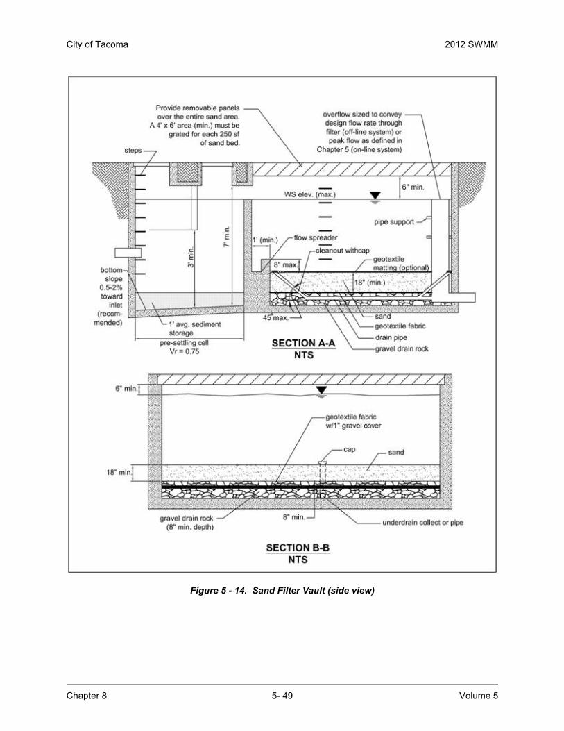
Figure 5 - 14. Sand Filter Vault (side view)
2012 SWMM City of Tacoma
Volume 5 5- 50 Chapter 8
8.7.2 BMP T820 Linear Sand Filter8.7.2.1 DescriptionLinear sand filters are typically long, shallow, two-celled, rectangular vaults. The first cell is designed for settling coarse particles, and the second cell contains the sand bed. Stormwater enters the second cell via a weir section that also functions as a flow spreader.
Figure 5 - 15 illustrates a linear sand filter.
8.7.2.2 Application and Limitations• Applicable in long narrow spaces such as the perimeter of a paved surface.
• As a part of a treatment train such as downstream of a filter strip, upstream of an infiltration system, or upstream of a wet pond or a biofilter for oil control.
• To treat small drainages (less than 2 acres of impervious area).
• To treat runoff from high-use sites for TSS and oil/grease removal, if applicable.
8.7.2.3 Additional Design Criteria for Linear Sand Filters• Divide the two cells by a divider wall that is level and extends a minimum of 12 inches
above the sand bed.
• Stormwater may enter the sediment cell by sheet flow or a piped inlet.
• The width of the sand cell must be 1-foot minimum to 15 feet maximum.
• The sand filter bed must be a minimum of 12 inches deep and have an 8-inch layer of drain rock with perforated drainpipe beneath the sand layer.
• The drainpipe must be 6-inch diameter minimum and be wrapped in geotextile and sloped a minimum of 0.5 percent to promote positive drainage.
• Maximum sand bed ponding depth: 12 inches.
• Must be vented as described above for sand filter vaults.
• Linear sand filters must conform to the materials and structural suitability criteria specified for wet vaults described in Chapter 8.
• Sediment cell width shall be selected based on sand filter width as follows:
Sand filter width, (w) inches 12-24 24-48 48-72 72+Sediment cell width, inches 12 18 24 w/3

City of Tacoma 2012 SWMM
Chapter 8 5- 51 Volume 5
Figure 5 - 15. Linear Sand Filter