chapter 9 multilevel signaling - · pdf filechapter 9 multilevel signaling ... like the same...
TRANSCRIPT
Chapter 9
MULTILEVEL SIGNALING
In order to increase the spectral efficiency to more than 1 b/s/Hz, without polarization-division multiplexing (PDM), multilevel signaling must be used to send more than two different choices of waveform per symbol. From Sec. 1.4 and Fig. 1.6, one of the major advan- tages of phase-modulated or coherent optical communication systems is the improvement of spectral efficiency with minimal degradation to receiver sensitivity. From the comparison of on-off keying (OOK) with quadrature-amplitude modulation (QAM) in Table 1.1, the energy per bit of 64-QAM signal is about the same as 4-00K signal but with three times the spectral efficiency. In this chapter, we will first discuss the methods to generate M-ary phase-shift-keying (PSK) and QAM signals with special emphasize in the popular differential quadrature phase-shift keying (DQPSK) signals. The performance of M-ary PSK and QAM sig- nals are analyzed when synchronous receiver is used with a phase-locked loop (PLL).
This chapter also analyzes the popular direct-detcction DQPSK sig- nal from Table 1.3. The direct-detection DQPSK receiver uses two in- terferometers to demodulate the two bits within the same symbol. The method in previous chapters to analyze differential phase-shift keying (DPSK) signal can be generalized to DQPSK signal. The performance of DQPSK signal with interferometer phase error, laser phase noise, and nonlincar phase noise are also calculated, mostly based on the series expansion of Appendix 4.A.
Although there are some initial experiments (Miyazaki and Kubota, 2004) and proposals (Han et al., 2004, Ohm, 2004), DQPSK signal re- mains the only choice for multilevcl signal. Together with polarization-
302 PHASE-MODULATED OPTICAL COMMUNICATION SYSTEMS
division multiplexing (PDM), the spectral efficiency of DQPSK signals is more than 2 b/s/Hz (Cho et al., 2004a,b).
1. Generation of Multilevel Signals From the low-pass representation of the signal of ~ , ( t ) e j4 . (~ ) , there
are many methods to generate multilevel signal. In an M-ary PSK sig- nal, the phase is divided into M evenly levels for M different waveforms. In an M-ary QAM signal, both the amplitude of A,(t) and the phase of &(t) are used for M different waveforms. While there are other varia- tions to use M different frequencies or only a real number of both positive and negative A,(t), those methods usually do not provide better spectral efficiency than M-ary QAM signals. For superior spectral efficiency, we focus on both M-ary PSK and QAM signals.
An M-ary PSK signal has a constant amplitude of A,(t) = A and M evenly spacing phases of Bk = ~ ( 2 k - l)/M, k = 1,2, . . . , M. The M different signal waveforms are
The Euclidean distance between the k and lth symbols is equal to
with a minimum Euclidean distance of &A sin TIM. Both quadrature phase-shift keying (QPSK) and DQPSK systems use
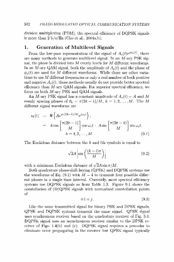
the waveforms of Eq. (9.1) with M = 4 to transmit four possible differ- ent phases in a single time interval. Currently, most spectral efficiency systems use DQPSK signals as from Tablc 1.3. Figure 9.1 shows the constellation of (D)QPSK signals with normalized constellation points of
& l z t j . (9.3)
Like the same transmitted signal for binary PSK and DPSK signals, QPSK and DQPSK systems transmit the same signal. QPSK signal uses synchronous receiver based on the quadraturc receiver of Fig. 3.4. DQPSK signal uses an asynchronous receiver similar to the DPSK re- ceiver of Figs. 1.4(b) and (c). DQPSK signal requires a precoder to eliminate error propagating in the rccciver but QPSK signal typically
Multilevel Signaling
Figure 9.1. The constellation of (D)QPSK signals
does not require a precoder. The design of DQPSK precoder is consid- ercd later.
QAM signal provides the highest spectral efficiency among all types of modulation scheme. In an M-ary QAM systems, if d% is an integcr, the M different signal waveforms are
sk(t) = A% {(ak + jbk)ejwct ) = akA cos w,t - bkA sin w,t,
ak,bk = - m + l , - m + 3 ,..., -1,+1, ..., , h - 1 .
(9.4)
Figure 1.6 shows a 64-QAM constellation in a square grid. For sim- plicity, we assume that all 64 points are used and transmit with equal probability. In general, QAM constellation may locate in irregular lo- cation for optimal performance (Foschini et al., 1974, Gockenbach and Kearsley, 1999). M-ary PSK signal can be considered as a special case of QAM signal. Different constellation point of a QAM signal also does not necessary to transmit in the samc probability. The system may achieve better performance with unequal probability for different constellation point by signal shaping (Calderbank and Ozarow, 1990, Laroia et al., 1994).
This section discusses two methods that generate QAM signal based on special (usually integrated) modulator or conventional dual-drivc Mach-Zehnder modulator of Fig. 2.13. The generation of QAM signal is used as an example.
304 PHASE-MODULATED OPTICAL COMMUNICATION SYSTEMS
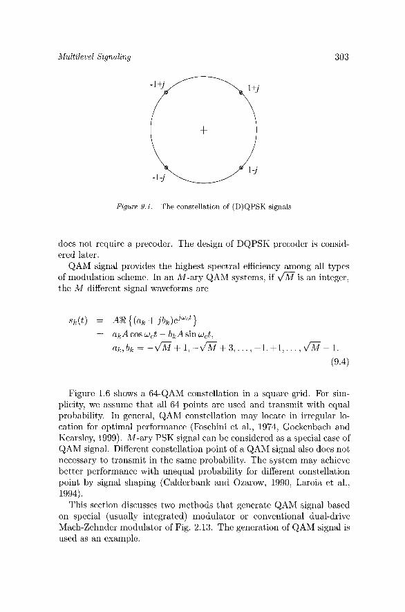
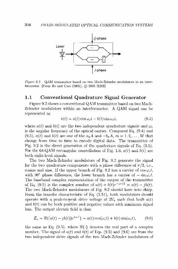
Figure 9.2. QAM transmitter based on two Mach-Zehnder modulators in an inter- ferometer. [From Ho and Cuei (2005). @ 2005 IEEE]
1.1 Conventional Quadrature Signal Generator Figurc 9.2 shows a convcntional &AM transmittcr bascd on two Mach-
Zchndcr modulators within an intcrfcromctcr. A QAM signal can bc rcprcscntcd as
s ( t ) = a(t) cos w,t + b(t) sinw,t, (9.5)
whcrc a( t) and b(t) arc thc two indcpcndcnt quadraturc signals and w, is the angular frequency of thc optical carricr. Compared Eq. (9.4) and (9.5), a ( t ) and b(t) arc onc of thc akA and -bkA, m = 1 ,2 , . . . , M that change from timc to timc to cncodc digital data. Thc transmitter of Fig. 9.2 is thc direct generation of the quadraturc signals of Eq. (9.5). For the 64-QAM rectangular constcllation of Fig. 1.6, a( t) and b(t) arc both cight-lcvcl signals.
The two Mach-Zchndcr modulators of Fig. 9.2 gcncratc the signal for the two quadrature components with a phase difference of 77-12, i.c., cosinc and sine. If the uppcr branch of Fig. 9.2 has a carricr of cosw,t, with 90" phase difference, the lower brarich has a carrier of - sinw,t. The baseband complcx rcprcscntation of thc output of the transmittcr of Eq. (9.5) is thc complex numbcr of a( t) + b(t)e-JnI2 = a(t) - jb(t). The two Mach-Zchndcr rnodulators of Fig. 9.2 should havc zcro chirp. From the transfer characteristic of Eq. (2.51), both niodulators should opcratc with a pcak-to-pcak drive voltage of 2Vn such that both a( t) and b(t) can be both positive and ncgativc values with mininlunl signal loss. The output clcctric ficld is thus
thc samc as Eq. (9.5), where R{.) dcnotcs thc real part of a complcx numbcr. The signal of a( t) and b(t) of Eqs. (9.5) and (9.6) arc from thc two indcpcndent drivc signals of thc two Mach-Zchndcr modulators of

M,ultilevel Signaling
Figure 9.3. Basic structure of a dual-drive Mach-Zehnder modulator with two inde- pendent phase modulators in a Mach-Zehnder interferometer.
Vl(t) and V2(t) in Fig. 9.2. Due to the nonlinear transfer characteristic of Eq. (2.51), the driving voltages of Vl(t) and V2(t) arc not necessary evenly spacing for evenly spacing signal of Eq. (9.5).
With two Mach-Zchndcr modulators and an intcrfcrometcr, the spe- cial modulator of Fig. 9.2 is difficult to fabricate. If the transmitter of Fig. 9.2 is inlplcnicntcd using discrete cornponcnts of two Mach-Zchndcr modulators within an intcrfcrometcr, the transmittcr is costly with many cornponcnts. The transmitter in Fig. 9.2 also requires two bias controls for the Mach-Zehndcr modulators and a phasc control of the 7r/2 phasc shifter. Most DQPSK demonstrations of Griffin and Carter (2002), Grif- fin ct al. (2003), Zhu et al. (2004b), and Cho ct al. (2003, 2004a,b) use an integrated transmittcr the samc as that shown in Fig. 9.2. The con- ventional QAM transmitter may be fabricated using electro-optic effect in semiconductor (Griffin et al., 2002, 2003, 2004) or LiNbOs (Cho ct al., 2004b). As shown later, QAM signal can also be gcncratcd using a single dual-drive Mach-Zchndcr modulator of Fig. 2.13.
1.2 Generation of QAM Signal Using a Single Dual-Drive Modulator
A QAM signal can also be gcncratcd using a conventional dual-drive Mach-Zehnder modulator. Figure 9.3 is the basic structure of a dual- drive Mach-Zchnder modulator, the samc as that of Fig. 2.13. The dual-drive Mach-Zchnder modulator consists of two phasc modulators that can be operated independently.
As shown in Scc. 2.3.2, Mach-Zehndcr modulator can be made us- ing various materials and LiNbOa is the most popular material. Almost all commercial long-haul dcnsc wavelength-division-multiplcxcd (WDM) systems use LiNbOs Mach-Zchndcr modulator. In the dual-drive struc- ture of Fig. 9.3, the modulator chirp is adjustable (Gnauck ct al., 1991, Ho and Kahn, 2004~). Currently, dual-drive 40 Gb/s modulator with a V, of less than 2 V has bcen fabricated (Sugiyama ct al., 2002).
306 PHASE-MODULATED OPTICAL COMMUNICATION SYSTEMS
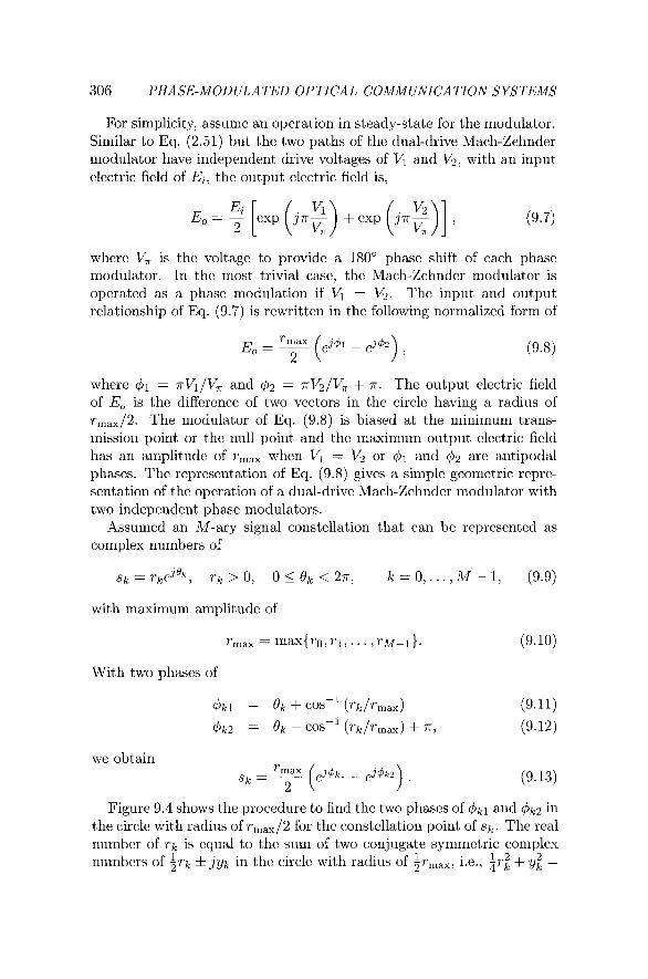
For simplicity, assume an operation in steady-state for the modulator. Similar to Eq. (2.51) but thc two paths of the dual-drive Mach-Zehnder modulator have independent drive voltages of Vl and V2, with an input electric field of Ei, the output electric field is,
where V, is the voltage to provide a 180" phase shift of each phase modulator. In the most trivial case, the Mach-Zehnder modulator is operated as a phase modulation if Vl = V2. The input and output relationship of Eq. (9.7) is rewritten in the following normalized form of
where = .rrVl/V, and 4 2 = .rrV2/V, + T . The output electric field of Eo is the difference of two vectors in the circle having a radius of rmax/2. The modulator of Eq. (9.8) is biased at the minimum trans- mission point or the null point and the maximum output electric field has an amplitude of r,, when Vl = V2 or and $2 are antipodal phases. The representation of Eq. (9.8) gives a simple geometric reprc- sentation of the operation of a dual-drive Mach-Zehnder modulator with two independent phase modulators.
Assumed an M-ary signal constellation that can be represented as complex numbers of
with maximum amplitude of
With two phases of
we obtain
2 (9.13)
Figure 9.4 shows the procedure to find thc two phases of 4k1 and $hk2 in the circle with radius of rmaX/2 for the constellation point of sk. The real number of r k is equal to the sum of two conjugate symmetric complex numbers of i r k & jyk in the circle with radius of $-,ax, i.c., $-: + y; =

Multilevel Signaling
Figure 9.4. The procedure to find 4kl and dkz for sk = rkejsk. [Adapted from Ho and Cuei (2005)l
1 2 - 4r,ax. With ( ~ k = COS-I (rk/rmax), we obtain irk * jyk = &-,,efj'+'k.
Figure 9.4 represents the two complex numbers of ;rma,ekj'+'k as two vectors in the phase angle of f pk with r k = ir,,ej'+'k + %-maxe-j'+'k, 2
Alternatively, we may rewrite the summation as the difference of
Figure 9.4 also shows the difference of Eq. (9.14) to find r k . The signal of sk = rkejok is a rotation of Bk from rk. If ejok is multiply to both sides of Eq. (9.14), we obtain the expression of Eq. (9.13) with and &!& given by Eq. (9.11) and Eq. (9.12), respectively. In Fig. 9.4, the three vectors of rk, ;rmaxej'+'k, and $-,axej(a-'+'k) are rotated by an angle of Bk to obtain rkejok, ,rmaxejbkl, and ;rmaxejbk2, respectively.
All constellation points of Eq. (9.9) can be generated based on two phase modulators having the phases of Eqs. (9.11) and (9.12), respec- tively. The decomposition of a QAM signal or arbitrary quadrature sig- nals into two phase-modulated signals was originated from Cox (1974) and Cox and Leck (1975). These types of linear amplification using nonlinear components (LINC) transmitter are very popular in wireless communications (Casadevall and Valdovinos, 1995, Shi and Sundstrom, 2000, Zhang et al., 2001). The two phases of Eqs. (9.11) and (9.12) drive the two phase modulators of Fig. 9.3 of the dual-drive Mach-Zehnder modulator.
308 PHASE-MOD ULATED OPTICAL COMMUNICATION SYSTEMS
(a) 16-QAM
(b) Big QPSK (r) 8PSK (d) Small QPSK
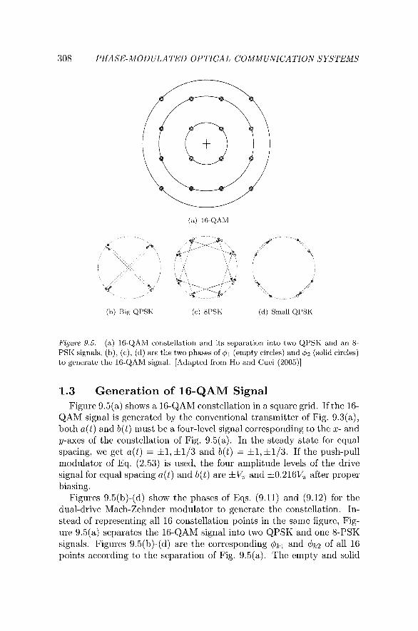
F Z ~ U T ~ 9.5. (a) 16-QAM constellation and its separation into two QPSK and an 8- PSK signals, (b); (c), (d) are the two phases of 41 (empty circles) and q5z (solid circles) to generate the 16-QAM signal. [Adapted from Ho and Cuei (2005)l
1.3 Generation of 16-QAM Signal Figure 9.5(a) shows a 16-QAM constellation in a square grid. If thc 16-
QAM signal is gcncratcd by the convcntional transmitter of Fig. 9.3(a), both a( t) and b(t) must bc a four-level signal corrcsponding to the x- and y-axes of the constcllation of Fig. 9.5(a). In the steady state for cqual spacing, we gct a( t) = f 1, f 113 and b(t) = f 1 , f 1 / 3 . If the push-pull modulator of Eq. (2.53) is uscd, thc four amplitude levels of the drive signal for cqual spacing a(t) and b(t) arc f V, and *0.216V, aftcr proper biasing.
Figurcs 9.5(b)-(d) show the phascs of Eqs. (9.11) and (9.12) for the dual-drivc Mach-Zehndcr modulator to gcncratc the constcllation. In- stcad of rcprcscnting all 16 constcllation points in the same figure, Fig- ure 9.5(a) separates thc 16-QAM signal into two QPSK and one 8-PSK signals. Figurcs 9.5(b)-(d) arc the corrcsponding qhkl and (,hk2 of all 16 points according to the separation of Fig. 9.5(a). Thc empty and solid
Multilevel Signaling 309
circles correspond to $ k l and (bk2, respectively. Figure 9.5(b) gives the QPSK signal of Fig. 9.5(a) with maximum amplitude of r,,,. For il- lustration purpose, the two closest points of Fig. 9.5(b) are the same but draw differently for the phases of two different signals. Figure 9.5(c) generates the &PSK signal of Fig. 9.5(a). Figure 9.5(d) gives the QPSK signal of Fig. 9.5(a) with the smallest amplitude.
From Figs. 9.5, the generation of a 16-QAM signal using a dual-drive Mach-Zehnder modulator requires the usage of a 16-level drive voltage and thus very complicated drive circuits. In the transmitter of Fig. 9.2, the two drive signals are two independent four-level drive signals cor- responding to the x and y axis of Fig. 9.5(a). Compared with the conventional transmitter of Fig. 9.2, the simplification of the optical components using a single dual-drive Mach-Zehnder modulator creates a high complexity in the electronic driving circuits. With the allowance of higher modulator loss, as shown later, the number of drive levels can be reduced.
2. Transmitter of (D)QPSK Signals DQPSK signal is by far the most popular multilevel signal for phasc-
modulated optical communications. The transmitter of (D)QPSK signal is considered here in more detail.
To generate the (D)QPSK signal using the conventional transmitter of Fig. 9.2, Vl(t), Vz(t) = f V, to provide the real and imaginary parts of Eq. (9.3) of f 1, respectively. With the phase shift of 7r/2, the output of the transmitter becomes that of Eq. (9.3) with s(t) = f cos(wct) f sin(wct) .
A (D)QPSK signal can also be generated by the cascade of two phase modulators both driven by binary signal. One modulator provides a phase modulation of 0 and 7r similar to DPSK signal and may used a zero-chirp amplitude modulator of Eq. (2.53). Another modulator pro- vides a phase modulation of f 7r/2 using a phase modulator. The am- plitude ripples from the driving signal of the phase modulator transfers to the phase ripple. However, the amplitude ripples for the amplitude modulator does not transfer to to the phase ripple.
Alternatively, the (D)QPSK signal of Eq. (9.3) can also generate using a phase modulator driven by a four-level signal to give the phases of f 7~/4 and f 3 ~ 1 4 . However, the four-level signal is difficult to operate.
When the dual-drive modulator transmitter of Fig. 9.3 is used to generate (D)QPSK signals with a constellation of Fig. 9.1. Similar to that of Fig. 9.5(b), Fig. 9.6(a) is the trivial case of operating the dual- drive Mach-Zehnder modulator as a phase modulator when and $2
arc antipodal phases. The four phases of Fig. 9.1 are generated by a four-
310 PHASE-MODULATED OPTICAL COMMUNICATION SYSTEMS
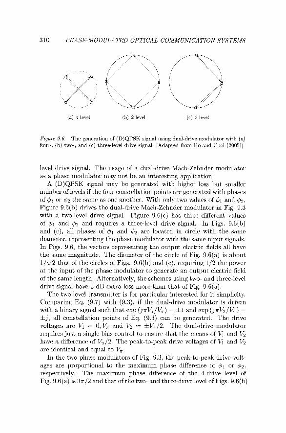
(a) 4 level (b) 2 level (c) 3 level
Figure 9.6. The generation of (D)QPSK signal using dual-drive modulator with (a) four-. (b) two-, and (c) three-level drive signal. [Adapted from Ho and Cuei (2005)l
lcvcl drive signal. The usage of a dual-drive Mach-Zchnder modulator as a phasc modulator may not bc an intercsting application.
A (D)QPSK signal may be gcncratcd with higher loss but smallcr number of levels if the four constellation points arc gcncratcd with phascs of $1 or $2 thc samc as one another. With only two values of and $2,
Figure 9.6(b) drives the dual-drive Mach-Zchndcr modulator in Fig. 9.3 with a two-level drive signal. Figure 9.6(c) has three different values of $1 and $2 and rcquircs a thrce-lcvel drivc signal. In Figs. 9.6(b) and (c), all phases of and $2 arc located in circlc with the samc diamctcr, rcprcscnting thc phasc modulator with the sarnc input signals. In Figs. 9.6, the vectors representing thc output electric fields all have the samc magnitude. The dianlctcr of the circlc of Fig. 9.6(a) is about 1/& that of the circlcs of Figs. 9.6(b) and (c), requiring 112 the power at thc input of thc phasc modulator to gcncratc an output electric field of thc samc length. Altcrnativcly, the schcmcs using two- and thrcc-lcvcl drivc signal havc 3-dB cxtra loss more than that of Fig. 9.6(a).
Thc two level transmitter is for particular intcrcstcd for it simplicity. Comparing Eq. (9.7) with (9.3), if the dual-drive modulator is drivcn with a binary signal such that exp (j.irK/V,) = 3Z1 and exp (jn&/V,) =
3Zj , all constellation points of Eq. (9.3) can bc gcncratcd. The drivc voltagcs arc Vl = 0, V, and V2 = *V,/2. The dual-drivc modulator requires just a single bias control to ensure that the means of Vl and V2 have a difference of V,/2. The pcak-to-peak drivc voltagcs of Vl and V2 arc identical and equal to V,.
In the two phasc niodulators of Fig. 9.3, the peak-to-pcak drive volt- ages are proportional to the maximum phase difference of & or 4 2 ,
respectively. The maximum phase difference of the 4-drive level of Fig. 9.6(a) is 3 ~ / 2 and that of the two- and thrce-drive level of Figs. 9.6(b)
M~ultile~uel Signaling
Dual-Drive RZ Mod
Encoder ........... Sync.
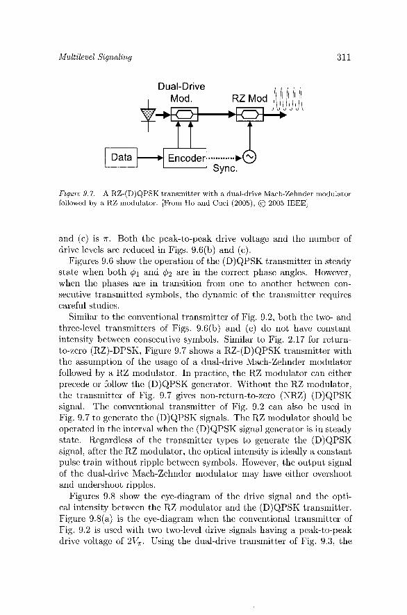
Figure 9.7. A RZ-(D)QPSK transmitter with a dual-drive Mach-Zehnder modulator followed by a RZ modulator. [From 130 and Cuei (2005): @ 2005 IEEE]
and (c) is T . Both the pcak-to-peak drive voltagc and the numbcr of drivc levels arc reduced in Figs. 9.6(b) and (c).
Figurcs 9.6 show the operation of the (D)QPSK transmitter in stcady statc whcn both and 42 are in the correct phasc anglcs. Howcvcr, whcn thc phases arc in transition from one to another betwcen con- secutive transmitted symbols, the dynamic of the transmitter requires careful studics.
Similar to the convtntional transmittcr of Fig. 9.2, both the two- and three-level transmittcrs of Figs. 9.6(b) and (c) do not havc constant intensity between consecutive symbols. Similar to Fig. 2.17 for rcturn- to-zero (RZ)-DPSK, Figurc 9.7 shows a RZ-(D)QPSK transrnittcr with the assunlption of the usage of a dual-drivc Mach-Zchndcr modulator followed by a RZ modulator. In practice, the RZ modulator can cithcr prcccdc or follow the (D)QPSK generator. Without the RZ modulator, the transmittcr of Fig. 9.7 gives non-return-to-zero (NRZ) (D)QPSK signal. Thc convcntional transmittcr of Fig. 9.2 can also be used in Fig. 9.7 to generate the (D)QPSK signals. The RZ modulator should be operated in the inttrval whcn the (D)QPSK signal generator is in stcady statc. Regardless of the transmittcr types to gcncratc the (D)QPSK signal, after the RZ modulator, the optical intensity is ideally a constant pulse train without ripple betwcen symbols. Howcvcr, the output signal of the dual-drive Mach-Zehnder modulator may havc cithcr overshoot and undershoot ripples.
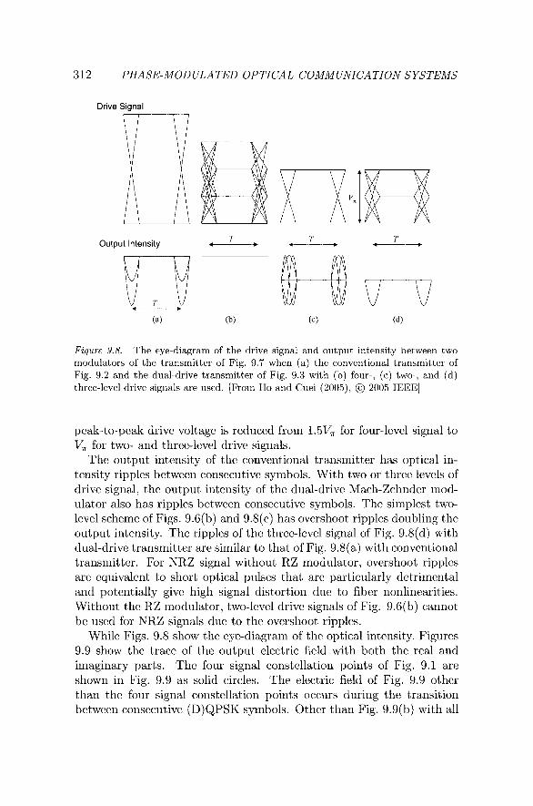
Figurcs 9.8 show the cyc-diagram of the drivc signal and the opti- cal intensity between the RZ modulator and the (D)QPSK transrnittcr. Figurc 9.8(a) is the eye-diagram whcn the convcntional transmittcr of Fig. 9.2 is used with two two-lcvcl drivc signals having a peak-to-pcak drive voltagc of 2V,. Using thc dual-drive transmittcr of Fig. 9.3, the
312 PHASE-MOD ULATED OPTICAL COMMUNICATION SYSTEMS
Drive Signal
Output Intensity T e-----r T *---------,
T *------*
Figure 9.8. The eye-diagram of the drive signal and output intensity between two modulators of the transmitter of Fig. 9.7 when (a) the conventional transmitter of Fig. 9.2 and the dual-drive transmitter of Fig. 9.3 with (b) four-, (c) two-, and (d) three-level drive signals are used. [From Ho and Cuei (2005), @ 2005 IEEE]
peak-to-peak drive voltage is reduced from 1.5V, for four-level signal to V, for two- and three-level drive signals.
The output intensity of the conventional transmitter has optical in- tensity ripples between consecutive symbols. With two or three levels of drive signal, the output intensity of the dual-drive Mach-Zehnder mod- ulator also has ripples between consecutive symbols. The simplest two- level scheme of Figs. 9.6(b) and 9.8(c) has overshoot ripples doubling the output intensity. The ripples of the three-level signal of Fig. 9.8(d) with dual-drive transmitter are similar to that of Fig. 9.8(a) with conventional transmitter. For NRZ signal without RZ modulator, overshoot ripples are equivalent to short optical pulses that are particularly detrimental and potentially give high signal distortion due to fiber nonlinearities. Without the RZ modulator, two-level drive signals of Fig. 9.6(b) cannot be used for NRZ signals due to the overshoot ripples.
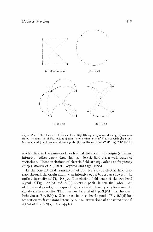
While Figs. 9.8 show the eye-diagram of the optical intensity, Figures 9.9 show the trace of the output electric field with both the real and imaginary parts. The four signal constellation points of Fig. 9.1 are shown in Fig. 9.9 as solid circles. The electric field of Fig. 9.9 other than the four signal constellation points occurs during the transition between consecutive (D)QPSK symbols. Other than Fig. 9.9(b) with all
Multilevel Signaling
(a) Conventional (b) 4 level
(c) 2 level (d) 3 level
Figure 9.9. The electric field locus of a (D)QPSK signal generated using (a) conven- tional transmitter of Fig. 9.2, and dual-drive transmitter of Fig. 9.3 with (b) four-, (c) two-, and (d) three-level drive signals. [From Ho arid Cuei (ZOOS), @ 2005 IEEE]
clcctric ficld in the samc circle with cqual distance to the origin (constant intcnsity), other traccs show that the clcctric ficld has a widc range of variations. Those variations of clcctric ficld arc equivalent to frequency chirp (Gnauck ct al., 1991, Koyama and Oga, 1988).
In the conventional transmitter of Fig. 9.9(a), the clcctric field may pass through thc origin and has an intensity cqual to zero as shown in the optical intcnsity of Fig. 9.8(a). The electric ficld trace of the two-level signal of Figs. 9.6(b) and 9.8(c) shows a peak clcctric field about 4 of thc signal points, corrcsponding to optical intcnsity ripples twice the steady-statc intcnsity. The three-lcvcl signal of Fig. 9.9(d) has the samc behavior as Fig. 9.9(a). Of course, the three-lcvcl signal of Fig. 9.9(d) has transition with constant intcnsity but all transitions of the convcntiorial signal of Fig. 9.9(a) have ripples.
314 PHASE-MOD ULATED OPTICAL COMMUNICATION SYSTEMS
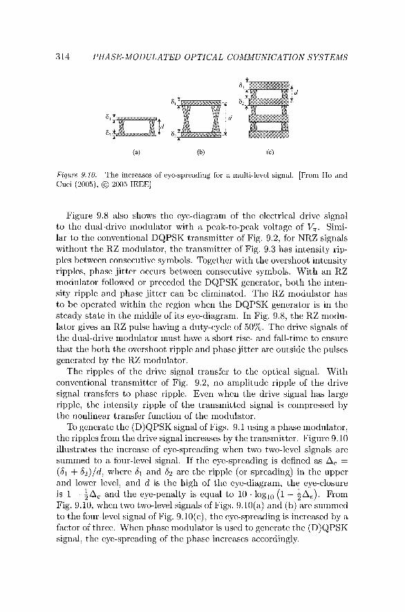
Fzgure 9.10. The increases of eye-spreading for a multi-level signal. [From Ho and Cuei (2005), @ 2005 IEEE]
Figurc 9.8 also shows the cye-diagram of the clcctrical drivc signal to the dual-drivc modulator with a peak-to-peak voltage of V,. Simi- lar to the convcntional DQPSK transmittcr of Fig. 9.2, for NRZ signals without the RZ modulator, the transmittcr of Fig. 9.3 has intcnsity rip- ples bctwccn consecutive symbols. Togcthcr with the overshoot intcnsity ripplcs, phasc jittcr occurs bctwcen consecutive symbols. With an RZ modulator followed or prcccdcd thc DQPSK generator, both the inten- sity ripplc and phasc jittcr can be climinatcd. Thc RZ modulator has to be opcratcd within the region whcn the DQPSK gcncrator is in the stcady state in the middlc of its cyc-diagram. In Fig. 9.8, the RZ modu- lator givcs an RZ pulse having a duty-cycle of 50%. The drivc signals of thc dual-drive modulator must havc a short rise- and fall-timc to ensure that thc both thc overshoot ripplc and phasc jittcr arc outside the pulscs generated by thc RZ modulator.
Thc ripplcs of the drivc signal transfcr to thc optical signal. With convcntional transmittcr of Fig. 9.2, no amplitude ripplc of thc drivc signal transfers to phasc ripplc. Even whcn the drivc signal has large ripplc, thc intensity ripplc of thc transmittcd signal is compressed by the nonlinear transfcr function of thc modulator.
To gencratc thc (D)QPSK signal of Figs. 9.1 using a phasc modulator, thc ripplcs from thc drivc signal incrcascs by thc transmittcr. Figurc 9.10 illustrates the increase of eye-spreading whcn two two-level signals are summed to a four-levcl signal. If the eye-spreading is defined as A, =
(dl + & ) I d , whcrc dl and d2 are the ripplc (or spreading) in thc upper and lowcr lcvcl, and d is the high of the cyc-diagram, the eye-closure is 1 - +A, and the cyc-pcnalty is equal to 1 0 . logln (1 - A ) . From Fig. 9.10, whcn two two-level signals of Figs. 9.lO(a) and (b) arc summed to the four-level signal of Fig. 9.10(c), thc eye-sprcading is incrcascd by a factor of thrcc. When phasc modulator is used to generate the (D)QPSK signal, the cyc-spreading of the phase incrcascs accordingly.
Multilevel Signaling 315
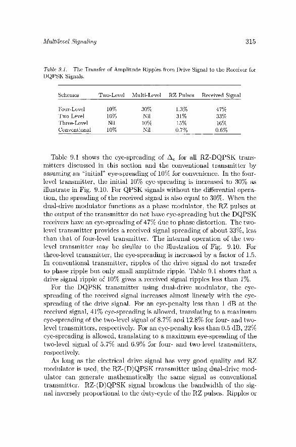
Table 9.1. The Transfer of Amplitude Ripples from Drive Signal to the Receiver for DQPSK Signals.
Schemes Two-Level Multi-Level RZ Pulses Received Signal
Four-Level 10% 30% 1.3% 47% Two-Level 10% Nil 31% 33% Three-Level Nil 10% 15% 16% Conventional 10% Nil 0.7% 0.6%
Table 9.1 shows the eye-spreading of A, for all RZ-DQPSK trans- mitters discussed in this section and the conventional transmitter by assuming an "initial" eye-spreading of 10% for convenience. In the four- level transmitter, the initial 10% eye-spreading is increased to 30% as illustrate in Fig. 9.10. For QPSK signals without the differential opera- tion, the spreading of the received signal is also equal to 30%. When the dual-drive modulator functions as a phase modulator, the RZ pulses at the output of the transmitter do not have eye-spreading but the DQPSK receivers have an eye-spreading of 47% due to phase distortion. The two- level transmitter provides a received signal spreading of about 33%, less than that of four-level transmitter. The internal operation of the two- level transmitter may be similar to the illustration of Fig. 9.10. For three-level transmitter, the eye-spreading is increased by a factor of 1.5. In conventional transmitter, ripples of the drive signal do not transfer to phase ripple but only small amplitude ripple. Table 9.1 shows that a drive signal ripple of 10% gives a received signal ripples less than 1%.
For the DQPSK transmitter using dual-drive modulator, the eye- spreading of the received signal increases almost linearly with the eye- spreading of the drive signal. For an eye-penalty less than 1 dB at the received signal, 41% eye-spreading is allowed, translating to a maximum eye-spreading of the two-level signal of 8.7% and 12.8% for four- and two- level transmitters, respectively. For an eye-penalty less than 0.5 dB, 22% eye-spreading is allowed, translating to a maximum eye-spreading of the two-level signal of 5.7% and 6.9% for four- and two-level transmitters, respectively.
As long as the electrical drive signal has very good quality and RZ modulator is used, the RZ-(D)QPSK transmitter using dual-drive mod- ulator can generate mathematically the same signal as conventional transmitter. RZ-(D)QPSK signal broadens the bandwidth of the sig- nal inversely proportional to the duty-cycle of the RZ pulses. Ripples or
316 PHASE-MODULATED OPTICAL COMMUNICATION SYSTEMS
eye-spreading transferred from the electrical drive signal are the major degradation using a phase modulator or dual-drive modulator to gener- ate (D)QPSK signals.
Most DQPSK demonstrations used an integrated transmitter in Grif- fin and Carter (2002), Griffin et al. (2003), Zhu et al. (2004b), and Cho et al. (2003, 2004a,b). DQPSK signals were also generated by the cas- cade of practically two phase modulators driven by two binary sequences in Kim and Essiambre (2003), Tokle et al. (2004), Wree et al. (2003a), and Yoshikane and Morita (2004a,b, 2005).
3. Synchronous Detection of Multilevel Signals Synchronous receiver with PLL to track the received phase gives the
best receiver sensitivity. With large number of signal levels, synchronous receiver is usually 3-dB better than the corresponding asynchronous re- ceiver. The multilevel quadrature signals may be M-ary PSK or QAM signals. Multilevel frequency-shift keying (FSK) signals do not provide good spectral efficiency and are not discussed here.
3.1 M-ary PSK Signal The synchronous quadrature receiver of Fig. 3.4 can be used to detect
the M-ary PSK signal of Eq. (9.1) where the M possible phases of Ok = ~ ( 2 k - l ) /M, k = 1,2 , . . . , M are used to carry the information. Assume that the receiver is limited by amplifier noise, when the phase of Ok is the transmitted, the phase distribution is pon(O - Ok), where pon(0) is from Eq. (4.A.7) in Appendix 4.A. When Gray code is used, the bit error probability is equal to
Using the series expansion of Eq. (4.A.12), the bit error probability is equal to
When M = 2 for binary PSK signal, the series of Eq. (9.16) is the same as that from Eq. (4.A.16), or ;erfc(fi) of Eq. (3.78).
The series summation of Eq. (9.16) is difficult to evaluate from Ap- pendix 4.A. The minimum Euclidean distance between the two closest
Multilevel Signaling
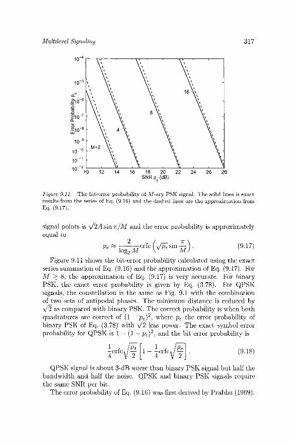
Figure 9.11. The bit-error probability of M-ary PSK signal. The solid lines is exact results from the series of Eq. (9.16) and the dashed lines are the approximation from Eq. (9.17).
signal points is &A sin T I M and the error probability is approximately equal to
Figure 9.11 shows the bit-error probability calculated using the exact series summation of Eq. (9.16) and the approximation of Eq. (9.17). For M 2 8, the approximation of Eq. (9.17) is very accurate. For binary PSK, the exact error probability is given by Eq. (3.78). For QPSK signals, the constellation is the same as Fig. 9.1 with the combination of two sets of antipodal phases. The minimum distance is reduced by 4 as compared with binary PSK. The correct probability is when both quadratures are correct of (1 - p,)2, where p, the error probability of binary PSK of Eq. (3.78) with & less power. The exact symbol error probability for QPSK is 1 - (1 - pe)2, and the bit error probability is
QPSK signal is about 3-dB worse than binary PSK signal but half the bandwidth and half the noise. QPSK and binary PSK signals require the same SNR per bit.
The error probability of Eq. (9.16) was first derived by Prabhu (1969).
318 PHASE-MOD ULA TED OPTICAL COMMUNICATION SYSTEMS
3.2 Quadrature Amplitude Modulation The M-ary QAM signal of Eq. (9.4) can also also be detected using
the synchronous quadrature receiver of Fig. 3.4. The average energy per symbol of the QAM signal of Eq. (9.4) is
For each dimension, the symbol error probability is
The symbol error probability for QAM signal is when both quadrature components are correct of 1 - (1 - px)(l - p y ) The bit error probability is
For M = 4, the error probability is the same as that of Eq. (9.18) for QPSK signal.
In high SNR, we obtain
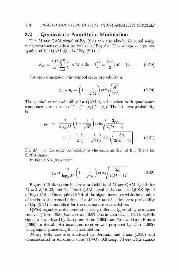
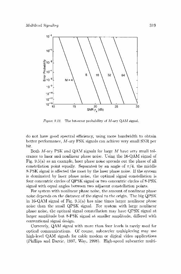
Figure 9.12 shows the bit-error probability of M-ary QAM signals for M = 4,8,16,32, and 64. The 4-QAM signal is the same as QPSK signal of Eq. (9.18). The required SNR of the signal increascs with the number of levels in thc constellation. For M = 8 and 32, the error probability of Eq. (9.21) is modified for the non-square constellation.
QPSK signal was demonstrated using different types of synchronous receiver (Derr, 1990, Kahn et al., 1992, Norimatsu et al., 1992). QPSK signal was analyzed by Barry and Kahn (1992) and Yamazaki and Emura (1990) in detail. An intradyne receiver was proposed by Derr (1992) using signal proccssing for demodulation.
M-ary FSK was also analyzed by Jeromin and Chan (1986) and demonstrated in Alexander et al. (1990). Although M-ary FSK signals
Multilevel Signaling
Figure 9.12. The bit-error probability of M-ary QAM signal.
do not have good spectral efficiency, using more bandwidth to obtain better performance, M-ary FSK signals can achieve very small SNR per bit.
Both M-ary PSK and QAM signals for large M havc vcry small tol- erance to laser and nonlinear phase noise. Using the 16-QAM signal of Fig. 9.5(a) as an example, laser phase noisc spreads out the phase of all constellation point equally. Separated by an angle of n/4, the middle 8-PSK signal is affected the most by the laser phase noise. If the system is dominated by laser phase noise, the optimal signal constellation is four concentric circles of QPSK signal or two concentric circles of &PSK signal with cqual angles betwcen two adjacent constellation points.
For systcm with nonlinear phase noise, the amount of nonlinear phase noise depends on the distance of the signal to the origin. Thc big QPSK in 16-QAM signal of Fig. 9.5(a) has nine times larger nonlinear phase noise than the small QPSK signal. For system with large nonlinear phase noise, the optimal signal constcllation may have QPSK signal at larger amplitude but 8-PSK signal at smaller amplitude, differed with conventional signal design.
Currently, QAM signal with more than four levels is rarely used for optical communications. Of coursc, subcarrier multiplcxing may use high-level QAM signals for cable modem or digital video applications (Phillips and Darcie, 1997, Way, 1998). High-speed subcarrier multi-

320 PHASE-MODULATED OPTICAL COMMUNICATION SYSTEMS
Figure 9.13. Direct-Detection Receiver for DQPSK Signals.
plcxing may also use high-level and high-speed QAM signals (Chcn and Way, 2004, Hui et al., 2002, Urick ct al., 2004). Equivalently an 8-QAM signal, DQPSK signal can also use together with amplitude-shift keying (ASK) signal (Hayasc ct al., 2004, Miyazaki and Kubota, 2004).
4. Direct-Detection of DQPSK Signal DPSK signal is demodulated using a direct-detection rcccivcr based
on the intcrfcromctric rccciver of Fig. 1.4(c). DQPSK rcccivcr uscs two asymmetric Mach-Zehnder interferometers for the differential phase of each quadrature component. Direct-detection DQPSK rccciver is the most popular rcccivcr for multilcvcl phase-modulated optical communi- cations from as Table 1.3.
4.1 Receiver Structure and Ideal Performance Figure 9.13 shows the direct-detection receiver for DQPSK signals.
The rcccivcd electric field of E, is splittcd into two paths of Z I C E , / ~ and passing through two asymmetric interferometers with phase difference of 7r/2. The two interferometers also have a path difference of the syrnbol time of T. With the rcccivcd signal of E, = A ~ " s ( ~ ) + n(t) , assuming ideal 3-dB coupler and balanced rcccivcr, the photocurrent of upper branch is
A2 iI (t) = , cos [4, (t) - 4, ( t - T ) + ~ / 4 ] + noisc tcrms. (9.23)
.&
the photocurrent of the lower branch is
A2 Z Q ( ~ ) = - cos[@,(t) - 4 - T) - ~ / 4 ] + noisc tcrms.
2
Without noise, a phase difference of 4,s (t) - 4,s (t - T) = 0" an output of iI(t) = iQ(t) = A2/2. A phase difference of 90"
givcs givcs
Multilevel Signaling 32 1
an output of iI(t) = A2/2 and iQ(t) = -A2/2. A phase difference of &(t) - $,(t - T) = 180" gives an output of iI(t) = iQ(t) = -A2/2. A phase difference of -90" gives an output of iI(t) = -A2/2 and iQ(t) = A2/2. The signs of both iI(t) and iQ(t) can map to the detected bits of the data.
In the simplest method, the error probability of DQPSK signal can be analyzed using the series expansion of Eq. (4.A.18). When the trans- mitted phases of consecutive symbols are the same, error occurs when the received differential phase is outside f 7r/4 or
Alternatively, a DQPSK signal is the same as the correlated binary signals of Sec. 3.3.6 with correlation coefficient of p = 1 / a . The crror probability is that of Eq. (3.119)
with
Equivalently speaking, the error probability of Eq. (9.26) is the same as that of DPSK signal with phase error of Eq. (4.10) when the phase error is 0, = 45".
The error probability of Eq. (9.26) ignores amplifier noise from or- thogonal polarization by assuming a polarized receiver. If the amplifier noise from orthogonal polarization is included, the error probability is the same as that of Eq. (4.11) for DPSK signal with the parameters a and b given by Eq. (9.27).
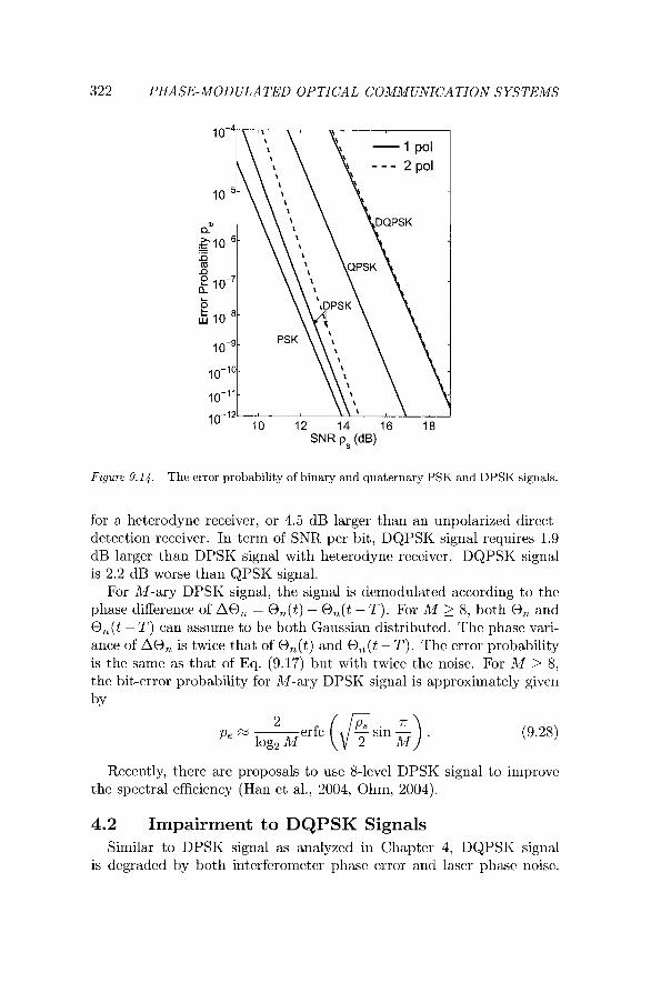
Figure 9.14 shows the error probability of DQPSK signal as a function of SNR p,. The error probability with and without amplifier noise from orthogonal polarization is almost the same. The error probability of binary PSK and QPSK signals of Eqs. (3.78) and (9.18) is also shown for comparison. The error probability for DPSK signal of Eq. (3.105) is also shown in Fig. 9.14.
For an error probability of lo-', DQPSK signal rcquires a SNR of p, = 17.9 dB, 4.9 dB larger than the requiremcnt of DPSK signal
322 PHASE-MOD ULATED OPTICAL COMMUNICATION SYSTEMS
Figure 9.14. The error probability of binary and quaternary PSK and DPSK signals.
for a heterodyne receiver, or 4.5 dB larger than an unpolarized direct- detection receiver. In term of SNR per bit, DQPSK signal requires 1.9 dB larger than DPSK signal with heterodyne receiver. DQPSK signal is 2.2 dB worse than QPSK signal.
For M-ary DPSK signal, the signal is demodulated according to the phase difference of A@, = O,(t) - O,(t - T). For M 2 8, both 0, and O,(t - T) can assume to be both Gaussian distributed. The phase vari- ance of A@, is twice that of O,(t) and O,(t - T). The error probability is the same as that of Eq. (9.17) but with twice the noise. For M 2 8, the bit-error probability for M-ary DPSK signal is approximately given by
erfc (6 sin +) . Pe log2 M
Recently, there are proposals to use 8-level DPSK signal to improve the spectral efficiency (Han et al., 2004, Ohm, 2004).
4.2 Impairment to DQPSK Signals Similar to DPSK signal as analyzed in Chapter 4, DQPSK signal
is degraded by both interferometer phase error and laser phase noise.
Multilevel Signaling 323
Similar to DPSK signal of Chapter 5, DQPSK signal is also degraded by nonlinear phase noise.
Interferometer Phase Error The performance of DPSK signal with interferometer phase error is
discussed in Sec. 4.2.1 based on an equivalent correlation coefficient. Without going into details, with phase error, the bit-error probability for DQPSK signal is
where 8, is the phase error of the asymmetric interferometer. From the two terms of Eq. (9.29), due to the phase error, the two adja-
cent points of the signal constellation of the DQPSK signal have different correlation coefficients. The correlated angles to the adjacent points are increased (corresponding to a+ and b+) or decreased (corresponding to a- and b-) by the phase error of 8, from n/4. In practice, the two asym- metric Mach-Zehnder interferometers of Fig. 9.13 may have two phase errors. The error probability is the average of the error probability given by Eq. (9.29) when the two phase errors are used in Eq. (9.29).
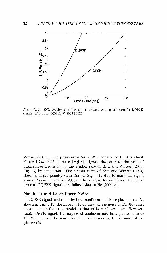
Figure 9.15 shows the SNR penalty as a function of phase error for DQPSK signals for polarized DQPSK receiver. The SNR penalty from Fig. 4.3 for DPSK signal with phase error is also shown for compari- son. The SNR penalty is calculated for a BER of lo-', corresponding to a required SNR of 13 and 17.9 dB for DPSK and DQPSK signals, respectively.
The curve of SNR penalty of a DQPSK signal in Fig. 9.15 has in- significant difference with the corresponding curves in Kim and Winzer (2003, Fig. 3), Bosco and Poggiolini (2003, Fig. 2), Bosco and Poggi- olini (2004b, Fig. 2), and Winzer and Kim (2003, Fig.5) (required the adjusting of x-axis).
For the same SNR penalty, the DQPSK signal is about 2.7 times more sensitive to the phase error than the DPSK signal, more or less the same ratio as the experimental and simulated results in Kim and
324 PHASE-MOD ULATED OPTICAL COMMUNICATION SYSTEMS
1
"0 10 20 30 40 Phase Error (deg)
Figure 9.15. SNR penalty as a function of interferometer phase error for DQPSK signals. [From Ho (2004a), @ 2005 IEEE]
Winzer (2003). The phase error for a SNR penalty of 1 dB is about 6" (or 1.7% of 360") for a DQPSK signal, the same as the ratio of mismatched frequency to the symbol rate of Kim and Winzer (2003, Fig. 3) by simulation. The measurement of Kim and Winzer (2003) shows a larger penalty than that of Fig. 9.15 due to non-ideal signal source (Winzer and Kim, 2003). The analysis for interferometer phase error to DQPSK signal here follows that in Ho (2004a).
Nonlinear and Laser Phase Noise
DQPSK signal is affected by both nonlinear and laser phase noise. As shown in Fig. 5.15, the impact of nonlinear phase noise to DPSK signal does not have the same model as that of laser phase noise. However, unlike DPSK signal, the impact of nonlinear and laser phase noise to DQPSK can use the same model and determine by the variance of the phase noise.
Multilevel Signaling 325
Similar to the error probability of Eqs. (9.16) and (5.77), with Gray code, the bit-error probability for DQPSK signal is always equal to
where the factor of 112 arises because a symbol error induces one bit error in the two-bit symbol. A symbol error occurs if the differential phase is outside the angles of f 7r/4. The summation of Eq. (9.26) includes all contribution from terms other than those in which m are integer multiple of 4 with sin(m7r14) = 0. The corresponding error probability for DPSK signals in Eq. (5.77) includes only all odd number terms.
With the exact model as from Eq. (5.70), ignored some constant phases, the coefficients for Eq. (9.30) are
with parameters similar to Eq. (5.71) of
where @@(u) is the characteristic function of normalized nonlinear phase noise depending solely on SNR ps given by Eq. (5.48). The parameters of r, are the "angular frequency" depending SNR.
When the nonlinear phase noise is approximated as Gaussian dis- tributed, similar to both Eqs. (4.40) and (5.82), the coefficients become
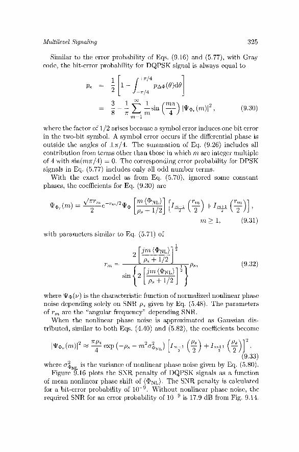
where aiNL is the variance of nonlinear phase noise given by Eq. (5.80). Figure 9.16 plots the SNR penalty of DQPSK signals as a function
of mean nonlinear phase shift of (@yqL). The SNR penalty is calculated for a bit-error probability of lo-'. Without nonlinear phase noise, the required SNR for an error probability of lo-' is 17.9 dB from Fig. 9.14.
326 PHASE-MOD ULATED OPTICAL COMMUNICATION SYSTEMS
Mean Nonlinear Phase Shift <Q, NL> (rad)
Figure 9.16. The SNR penalty as a function of mean nonlinear phase shift. The penalty is calculated by exact model or approximating the nonlinear phase noise as Gaussian distributed.
For comparison purpose, the SNR penalty of DPSK signal from Fig. 5.13 is also shown in Fig. 9.16. For the same mean nonlinear phase shift, the performance of DPSK signal is 0.5 to 0.8 dB better than DQPSK signal.
For a SNR penalty of less than 1 dB, the mean nonlinear phase shift must be less than 0.50 rad. The performance of a system increases with the SNR that is also proportional to the launched power of the signal. As shown earlier by Eq. (6.16), the mean nonlinear phase shift is proportional to the launched power of the system. From Fig. 9.16, the SNR penalty increases with the mean nonlinear phase shift. The optimal operating point can be found by the condition that the increase of SNR penalty is smaller than the SNR improvement. From Fig. 9.16, the optimal operating point is for a mean nonlinear phase shift of (aNL) = 0.89 rad. The optimal operating point is about 0.1 rad less than 0.97 rad for DPSK signal from Table 5.1, corresponding to a difference of 0.75 dB.
In term of mean nonlinear phase shift, DQPSK and DPSK systems have more or less the same tolerance to nonlinear phase noise. The mean nonlinear phase shift is proportional the product of the number of fiber spans and the launched power per span by Eq. (6.16). Alternativcly

Multilevel Signaling
Normalized Linewidth, A f, T
Figure 9.17. The SNR penalty as a function of the STD of nonlinear phase noise and normalized laser linewidth.
speaking, DQPSK and DPSK systems can tolerate the same amount of self-phase modulation.
The claim that DQPSK and DPSK systems can have the same amount of nonlinear phase noise is counter-intuitive. In fact, the variance of non- linear phase noise decreases with SNR. From Fig. 9.14, comparing with the 13.0 dB SNR requirement for DPSK signal, DQPSK signals with an SNR requirement of 17.9 dB have a variance of nonlinear phase noise 4.9 dB less than that for DPSK signal for the same mean nonlinear phase shift. Due to larger SNR requirement, DQPSK signals can tol- erate a mean nonlinear phase shift close to DPSK signals although the constellation points are closer than that for DPSK signal.
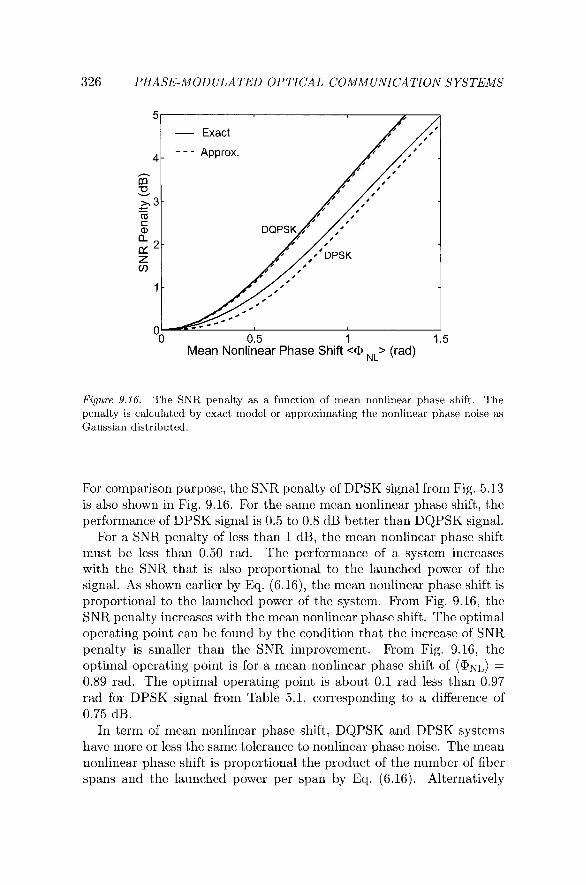
Based on the Gaussian approximation of nonlinear phase noise, Fig- ure 9.17 shows the SNR penalty of DQPSK and DPSK signals as a func- tion of the standard deviation (STD) of nonlinear phase noise. DQPSK signal can tolerate a nonlinear phase noise STD about half of that for DPSK signal. At the optimal operation point, DQPSK signal can toler- ate a nonlinear phase noise STD about 53% that for DPSK signal.
Requiring about 4.9 dB larger SNR but a bandwidth half of that of DPSK signals, for the same spectral density of amplifier noise, DQPSK signals require about 1.9 dB larger launched power for the same SNR.
328 PHASE-MODULATED OPTICAL COMMUNICATION SYSTEMS
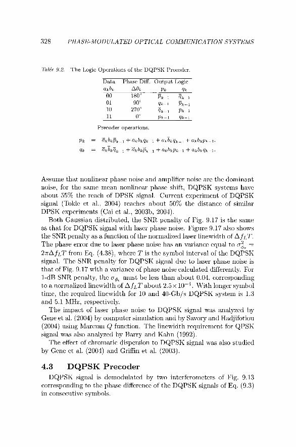
Table 9.2. The Logic Operations of the DQPSK Precoder.
Data Phase Diff. Output Logic
Precoder operations:
Assume that nonlinear phase noise and amplifier noise are the dominant noise, for the same mean nonlinear phase shift, DQPSK systems have about 55% the reach of DPSK signal. Current experiment of DQPSK signal (Tokle et al., 2004) reaches about 50% the distance of similar DPSK experiments (Cai et al., 2003b, 2004).
Both Gaussian distributed, the SNR penalty of Fig. 9.17 is the same as that for DQPSK signal with laser phase noise. Figure 9.17 also shows the SNR penalty as a function of the normalized laser linewidth of A fLT. The phase error due to laser phase noise has an variance equal to a$e =
2rA fLT from Eq. (4.38), where T is the symbol interval of the DQPSK signal. The SNR penalty for DQPSK signal due to laser phase noise is that of Fig. 9.17 with a variance of phase noise calculated differently. For 1-dB SNR penalty, the must be less than about 0.04, corresponding to a normalized linewidth of A fLT about 2.5 x With longer symbol time, the required linewidth for 10 and 40-Gb/s DQPSK system is 1.3 and 5.1 MHz, respectively.
The impact of laser phase noise to DQPSK signal was analyzed by Gene et al. (2004) by computer simulation and by Savory and Hadjifotiou (2004) using Marcum Q function. The linewidth requirement for QPSK signal was also analyzed by Barry and Kahn (1992).
The effect of chromatic dispersion to DQPSK signal was also studied by Gene et al. (2004) and Griffin et al. (2003).
4.3 DQPSK Precoder DQPSK signal is demodulated by two interferometers of Fig. 9.13
corresponding to the phase difference of the DQPSK signals of Eq. (9.3) in consecutive symbols.
Multilevel Signaling
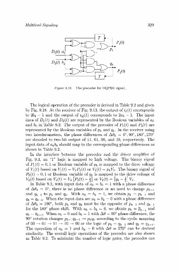
Figure 9.18. The precoder for DQPSK signal.
The logical operation of the precoder is derived in Table 9.2 and given by Fig. 9.18. At the receiver of Fig. 9.13, the output of i I ( t ) corresponds to 2bk - 1 and the output of i Q ( t ) corresponds to 2ak - 1. The input data of Dl ( t ) and D2(t ) are represented by the Boolean variables of a k
and bk in Table 9.2. The output of the precoder of Pl(t) and P2(t) are represented by the Boolean variables of p k and q k . In the receiver using two interferometers, the phase differences of A& = 0") 90°, 180°, 270" are decoded to two-bit output of 11, 01, 00, and 10, respectively. The input data of akbk should map to the corresponding phase differences a shown in Table 9.2.
In the interface between the precoder and the drivcr amplifier of Fig. 9.3, an "1" logic is mapped to high voltage. The binary signal of Pl(t) = 0 , l or Boolean variable of p k is mapped to the drive voltage of Vl ( t ) based on Vl ( t ) = V,Pl ( t ) or Vl ( t ) = pkV,. The binary signal of P2(t) = 0 , l or Boolean variable of q k is mapped to the drive voltage of V2(t) based on Vz(t) = V, [p2(t) - &] or V2(t) = [qk - i] V,.
In Table 9.2, with input data of a k = bk = 1 with a phase difference of A& = 0°, there is no phase difference or no need to change pk-1
and qk-1 to p k and q k . With ar, = bk = 1, we obtain p k = pk-1 and q k = qk-1. When the input data are a k = bk = 0 with a phase difference of Aek = 180") both p k and qk must be the opposite of pk-1 and qk-1
for the 180" phase shift. With a k = bk = 0, we obtain pk = pkP1 and qk = ?jk-l. When a k = 0 and bk = 1 with A0 = 90" phase difference, the 90" rotation changes pk- lqk -1 -+ p k q k according to the cyclic mapping of 00 -+ 01 -t 11 -+ 10 -+ 00 or the logic of p k = qk-1 and q h = ijk-l. The opcration of a k = 1 and bk = 0 with A0 = 270" can be derivcd similarity. The overall logic operations of the precoder are also shown in Table 9.2. To minimize the number of logic gates, the precoder can
330 PHASE-MODULATED OPTICAL COMMUNICATION SYSTEMS
be simplified to
where @ denotes exclusive-OR operation. The precoder of Eq. (9.34) is also shown in Fig. 9.18.
5. Direct-Detection of Multilevel On-Off Keying Signals
On-off keying signals may also have more than two levels. A four- level on-off keying is shown in Fig. 1.6 as an example. Including the noise from orthogonal polarization and assuming an optical matched filter preceding the receiver, the received signal is the same as that of Eq. (3.125)
for M-ary on-off keying signal, where Ak is the amplitude for the kth signal waveform. The M waveforms are assumed to be transmitted with equal probability but signal shaping may provide better performance (Shiu and Kahn, 1999). Also the same as that in Eq. (3.126), the prob- ability density function (p.d.f.) of the output signal is a noncentral X 2
distribution with four degrees of freedom of
with a mean and variance of
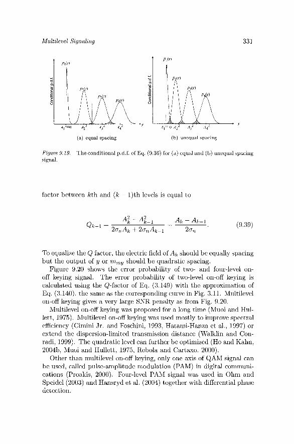
Figure 9.19 shows the conditional p.d.f. of Eq. (9.36) for equal and unequal spacing signal. The variance of a$ increases with A; and the upper two levels have the largest noise variance. If the on-off keying signal has equal spacing in myk, from Fig. 9.19(a), the systcm is lim- ited by the upper two levels. The system should be designed for equal error probability between levels, as shown in Fig. 9.19(b), with unequal spacing in myk. While the exact analysis is difficult, a Gaussian ap- proximation using Q factor similar to that of Eq. (3.140) is vcry simple. The analysis can further be simplified if the variance of Eq. (9.38) is approximated a: z 40:~; for k > 1. With the approximation, thc Q
Mult.ileue1 Signaling
(a) equal spacing (b) unequal spacing
Figure 9.19. The conditional p.d.f. of Eq. (9.36) for (a) equal and (b) unequal spacing signal.
factor bctwccn lcth and ( k - 1)th levcls is equal to
To equalize the Q factor, the clcctric ficld of Ak should bc cqually spacing but the output of y or mTny should be quadratic spacing.
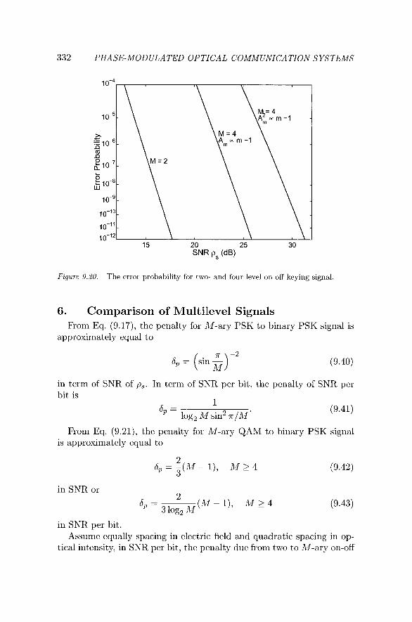
Figurc 9.20 shows thc error probability of two- and four-level on- off keying signal. The error probability of two-level on-off keying is calculatcd using the Q-factor of Eq. (3.149) with the approximation of Eq. (3.140), thc same as the corresponding curve in Fig. 3.11. Multilcvcl on-off keying gives a very large SNR penalty as from Fig. 9.20.
Multilevel on-off keying was proposed for a long time (Muoi and Hul- lett, 1975). Multilevel on-off keying was used niostly to irnprovc spectral efficiency (Cimini Jr. and Foschini, 1993, Hatami-Hanza et al., 1997) or extend the dispcrsion-lirnitcd transmission distancc (Walklin and Con- radi, 1999). The quadratic level can further be optimized (Ho and Kahn, 2004b, Muoi and Hullctt, 1975, Rebola and Cartaxo, 2000).
Other than multilevel on-off keying, only one axis of QAM signal can bc uscd, callcd pulsc-amplitude modulation (PAM) in digital communi- cations (Proakis, 2000). Four-lcvcl PAM signal was uscd in Ohm and Speidel (2003) and Hansryd et al. (2004) together with differential phase detection.
332 PHASE-MODULATED OPTICAL COMMUNICATION SYSTEMS
Figure 9.20. The error probability for two- and four-level on-off keying signal.
6. Comparison of Multilevel Signals From Eq. (9.17), the penalty for M-ary PSK to binary PSK signal is
approximately equal to
in term of SNR of p,. In term of SNR per bit, the penalty of SNR per bit is
1
6 - L
(9.41) * - log2 M sin2 x /M '
From Eq. (9.21), the penalty for M-ary QAM to binary PSK signal is approximately equal to
in SNR per bit. Assume equally spacing in electric field and quadratic spacing in op-
tical intensity, in SNR per bit, the penalty due from two to M-ary on-off
Multilevel Signaling
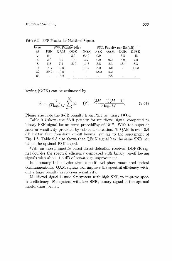
Table 9.3. SNR Penalty for Multilevel Signals.
Level SNR Penalty (dB) SNR Penalty per Bit(dB) M PSK QAM OOK DPSK PSK QAM OOK DPSK 2 0.0 - 3.5 0.45 0.0 - 3.5 .45 4 3.0 3.0 11.9 5.2 0.0 0.0 8.9 2.2 8 8.3 7.4 18.5 11.3 3.5 2.6 13.7 6.5 16 14.2 10.0 - 17.2 8.2 4.0 11.2 32 20.2 13.0 - - 13.2 6.0 64 - 16.2 - 8.5
keying (OOK) can be estimated by
2 M
6 - (2M - l ) ( M - 1) C (m - I), = '- Mlog,M 3 log, M
(9.44) m=l
Please also note the 3-dB penalty from PSK to binary OOK. Table 9.3 shows the SNR penalty for multilevel signal compared to
binary PSK signal for an error probability of lo-'. With the superior receiver sensitivity provided by coherent detection, 64-QAM is even 0.4 dB better than four-level on-off keying, similar to the assessment of Fig. 1.6. Table 9.3 also shows that QPSK signal has the same SNR per bit as the optimal PSK signal.
With an interferomctric based direct-detection receiver, DQPSK sig- nal doubles the spectral efficiency compared with binary on-off keying signals with about 1.3 dB of sensitivity improvement.
In summary, this chapter studies multilevel phase-modulated optical communications. QAM signals can improve the spectral efficiency with- out a large penalty in receiver sensitivity.
Multilevel signal is used for system with high SNR to improve spec- tral efficiency. For system with low SNR, binary signal is the optimal modulation format.