chapter 6designforstrength.com/chapter-06.pdf · is based on a portion of the total strain energy...
TRANSCRIPT

Design for Strength and Endurance – Chapter 6
_____________________________________________________________________________________ Theories of Static Failure - - C.F. Zorowski 2002 121
Chapter 6 Theories of Static Failure
Screen Titles
Introduction Design Scenario Issues Designer’s Dilemma Theories of Failure Max Normal Stress Theory –1, 2 Max Shear Stress Theory – 1, 2 Distortion Energy Theory – 1, 2 Mohr’s Theory Coulomb Mohr Theory – 1, 2 Ductile Material Failure Applicable Theories Brittle Failure Modified Coulomb – Mohr Applicable Theories Example Problem Review Exercise Off Line Exercises
Design for Strength and Endurance – Chapter 6
____________________________________________________________________________________Theories of Static Failure - - C.F. Zorowski 2002 122
Design for Strength and Endurance – Chapter 6
____________________________________________________________________________________Theories of Static Failure - - C.F. Zorowski 2002 123
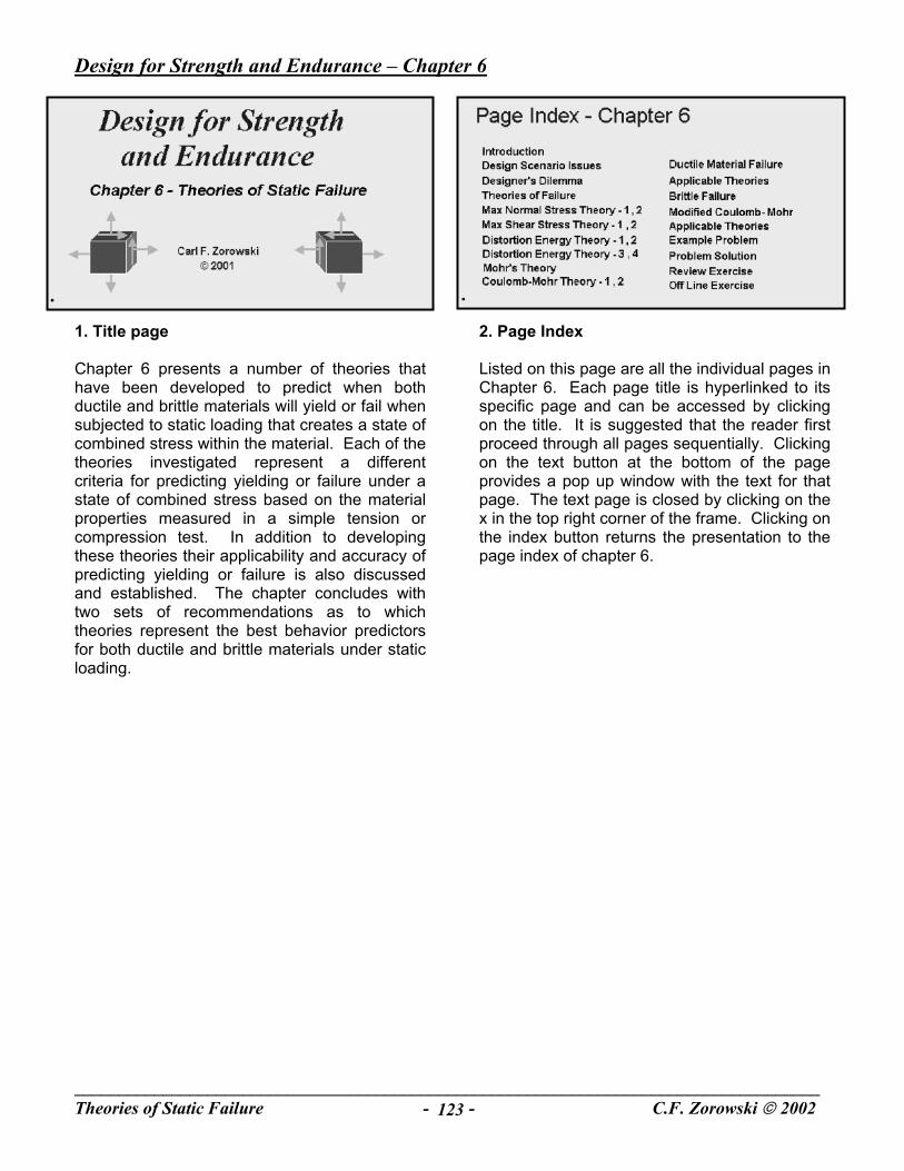
1. Title page Chapter 6 presents a number of theories that have been developed to predict when both ductile and brittle materials will yield or fail when subjected to static loading that creates a state of combined stress within the material. Each of the theories investigated represent a different criteria for predicting yielding or failure under a state of combined stress based on the material properties measured in a simple tension or compression test. In addition to developing these theories their applicability and accuracy of predicting yielding or failure is also discussed and established. The chapter concludes with two sets of recommendations as to which theories represent the best behavior predictors for both ductile and brittle materials under static loading.
2. Page Index Listed on this page are all the individual pages in Chapter 6. Each page title is hyperlinked to its specific page and can be accessed by clicking on the title. It is suggested that the reader first proceed through all pages sequentially. Clicking on the text button at the bottom of the page provides a pop up window with the text for that page. The text page is closed by clicking on the x in the top right corner of the frame. Clicking on the index button returns the presentation to the page index of chapter 6.

Design for Strength and Endurance – Chapter 6
____________________________________________________________________________________Theories of Static Failure - - C.F. Zorowski 2002 124
3. Introduction Ideally, a part designer should have available results from a great many tests for the material chosen for the part to insure that the design decisions made will provide the strength and endurance desired for its final application. It would be best if these tests could be performed on materials possessing the identical properties of alloying, processing and heat treatment to be used in the part as well as being loaded in a similar manner as the part being designed, that is in tension, bending, torsion and/or combined loads applied statically or dynamically as specified by the design requirements. In other words actually testing the part itself. Unfortunately, this is seldom possible. Whether this is practical, possible or feasible is a consequence of how the design fits into an overall design scenario defined by issues involving varying degrees of safety, production volume, cost and available time.
4. Design Scenario Issues The issues that impact a design are many and varied with different influences on the testing that takes place on the materials that go into the design prior to or during the design process. Material testing may cover a wide spectrum that includes a simple tensile test at one end to complex life tests of prototype parts at the other. Listed here are five design scenario issues that vary in their effect on material testing that may take place. The issue of public safety is the most prominent. Any likelihood of endangerment of life or significant physical harm from material failure dictates extensive testing that provides the best material properties or part behavior available. The question then becomes when has enough testing been performed. Production volume impacts material testing in that the cost of testing will impact the final cost of the part. Where the production volume is high an extensive testing program may represent only a small portion of the final part cost. The greater the importance of operational reliability in the final product the more justifiable an appropriate material testing program irrespective of its cost. The space program is a good example. There are also instances in which the time available for an extensive testing program simply isn’t available. It is hoped that this never has to be the case but instances may arise. When parts fail with undesirable effects there is always the question of whether sufficient testing was undertaken as well as were the results properly interpreted and applied.
Design for Strength and Endurance – Chapter 6
____________________________________________________________________________________Theories of Static Failure - - C.F. Zorowski 2002 125
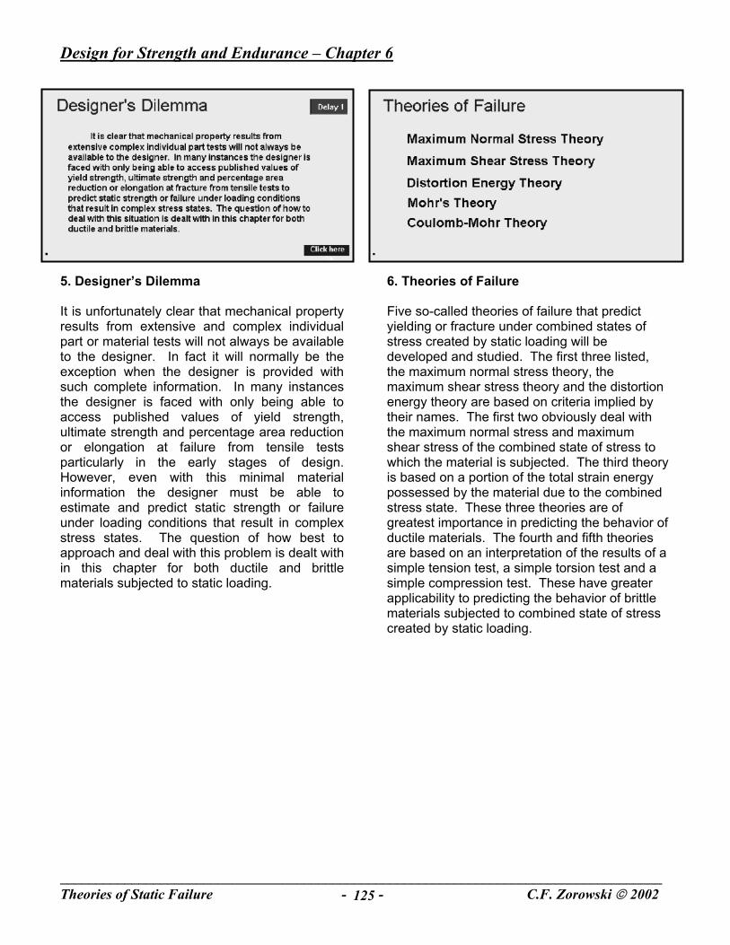
5. Designer’s Dilemma It is unfortunately clear that mechanical property results from extensive and complex individual part or material tests will not always be available to the designer. In fact it will normally be the exception when the designer is provided with such complete information. In many instances the designer is faced with only being able to access published values of yield strength, ultimate strength and percentage area reduction or elongation at failure from tensile tests particularly in the early stages of design. However, even with this minimal material information the designer must be able to estimate and predict static strength or failure under loading conditions that result in complex stress states. The question of how best to approach and deal with this problem is dealt with in this chapter for both ductile and brittle materials subjected to static loading.
6. Theories of Failure Five so-called theories of failure that predict yielding or fracture under combined states of stress created by static loading will be developed and studied. The first three listed, the maximum normal stress theory, the maximum shear stress theory and the distortion energy theory are based on criteria implied by their names. The first two obviously deal with the maximum normal stress and maximum shear stress of the combined state of stress to which the material is subjected. The third theory is based on a portion of the total strain energy possessed by the material due to the combined stress state. These three theories are of greatest importance in predicting the behavior of ductile materials. The fourth and fifth theories are based on an interpretation of the results of a simple tension test, a simple torsion test and a simple compression test. These have greater applicability to predicting the behavior of brittle materials subjected to combined state of stress created by static loading.

Design for Strength and Endurance – Chapter 6
____________________________________________________________________________________Theories of Static Failure - - C.F. Zorowski 2002 126
7. Maximum Normal Stress Theory - 1 In all the theory developments that follow their application will be limited to a general two-dimensional state of stress. This makes understanding the development and application of the theory easier. In addition most loading cases can be reduced to creating a two-dimensional state of stress anyway. The maximum normal stress theory simply proposes that yielding will occur in a material when the maximum normal stress in a combined stress state in that material is equal to the maximum normal stress in a simple tension test. Any general two-dimensional state of stress can be defined in terms its two principal stresses sigma 1 and sigma 2. Assume that these are ordered as listed. i.e. sigma 1 is greater than zero (tensile) and sigma two is negative (compressive). This theory predicts that yielding will take place when sigma 1 is equal to the yield stress, sigma y in tension, or when sigma 2 is equal to minus sigma y in compression whichever occurs first. This can best be visualized in terms of a graphical representation of these limiting criteria as depicted on the next page.
8. Maximum Normal Stress Theory - 2 The maximum normal stress theory in two dimensions is best visualized by plotting the limiting conditions imposed by the theory on a two dimensional axis system defined by sigma 1 and sigma 2 coordinates as illustrated. If sigma 1 and sigma 2 are both positive, that is the stress state lies in the first quadrant then the material will not yield unless either sigma 1 or sigma 2 are equal to the yield stress sigma y. The points sigma y super t on the two axes represent states of simple tension. Since the yield stress in simple compression might be numerically higher than the yield stress in tension the diagram can be shown as extended somewhat in the second, third and fourth quadrants to the limiting values of sigma y super c for simple compression on the negative sigma 1 and negative sigma 2 axes. Then if sigma 1 is positive and sigma 2 is negative, that is the fourth quadrant, then yielding is defined by the theory if either sigma 1 has a value of sigma y super t or sigma 2 becomes equal to minus sigma y super c. In a similar fashion the yielding boundaries in the second and third quadrants can be defined in a similar fashion as prescribed by the theory. Any state of two dimensional stress that lies inside the rectangular figure denotes a condition that yielding will not occur whereas a state of combined stress on any boundary of the figure indicates that yielding will occur. This theory is a pretty good predictor in the first and third quadrants but not in the second and fourth.

Design for Strength and Endurance – Chapter 6
____________________________________________________________________________________Theories of Static Failure - - C.F. Zorowski 2002 127
9. Maximum Shear Stress Theory - 1 The maximum shear stress theory proposes that yielding will occur in a material subjected to a combined state of stress when the maximum shear stress is equal to the maximum shear stress experienced by material in a simple tension test. For simplicity it will be assumed that the yield stress in tension and the yield stress in compression for a ductile material will be equal. This is not unreasonable. The maximum shear stress in a simple tension test is just equal to one half the tensile yield stress or sigma y over 2. For a two-dimensional stress state in which sigma 1 and sigma 2 are the principal stresses and sigma 1 is greater than sigma 2 the maximum shear stress is given by the quantity sigma 1 minus sigma 2 divided by 2. Hence the maximum shear stress theory stated analytically is that sigma 1 minus sigma 2 is equal to sigma yield. If sigma 2 is greater than sigma 1 then the expression of the maximum shear stress theory is that sigma 2 minus sigma 1 is equal to sigma yield. Again this can be best visualized graphically as presented on the next page.
10. Maximum Shear Stress Theory - 2 The equation sigma 1 minus sigma 2 equal to sigma y is a 45-degree line that passes through the points sigma y on the sigma 1 axis and minus sigma y on the negative sigma 2 axis. In a similar manner the equation sigma 2 minus sigma 1 equal to sigma y is also a 45-degree line that passes through sigma y on the positive sigma 2 axis and minus sigma y on the negative sigma 1 axis. These two lines define the limiting condition for yielding as predicted by the maximum shear stress theory. Any state of stress that lies between these two lines will not produce yielding while any point on either line will result in yielding of the material. Note that this implies that very large, in fact infinite values of sigma 1 equal to sigma 2 will not predict yielding. This of course is not reasonable. However, it has already been stated that the maximum normal stress theory is a pretty good predictor in quadrants one and three. Hence a combination of the maximum normal stress theory in quadrants one and three together with the maximum shear stress theory in quadrants two and four might well be a good combination. This will be seen later to be quite acceptable for ductile materials.

Design for Strength and Endurance – Chapter 6
____________________________________________________________________________________Theories of Static Failure - - C.F. Zorowski 2002 128
11. Yielding in Pure Shear Before going on determine the value of the maximum shear stress to produce the onset of yielding in a load state of pure torsion, that is a circular shaft subjected to a twisting torque about its central axis based on the maximum shear stress theory. After solving the problem click on the solution button to check your answer.
(Solution on Page 142)
12. Distortion Energy Theory - 1 The distortion energy theory is based on using a portion of the total strain energy contained in a material subjected to a combined stress state as its criteria for establishing the onset of yielding. More specifically it recognizes that the work done on a material under load can be expressed as energy due to volume change and energy due to distortion of shape. The theory states that yielding will take place when the energy per unit volume due to distortion under combined stress is equal to the distortion energy per unit volume at yielding in a simple tension test. The distortion energy is determined by subtracting the energy due to volume change from the total strain energy. This is done for a material under combined stress and then set equal to this same quantity for a simple tension test. The detailed development follows on the next several pages.

Design for Strength and Endurance – Chapter 6
____________________________________________________________________________________Theories of Static Failure - - C.F. Zorowski 2002 129
13. Distortion Energy Theory - 2 In this development it is necessary to begin with a general three-dimensional state of stress and then reduce the final result to two dimensions for comparison to the maximum normal stress and maximum shear stress theories. The total strain energy per unit volume in terms of the principal stresses in three-dimensions is given by the first equation. Note that it contains both the modulus of the material and Poisson’s ratio since it will be dependent on the specific material being loaded. To review the development of this expression for total strain energy click on the review button and return here when the review is completed. The stain energy per unit volume due to volume change is determined by first defining an average principal stress as one-third the sum of the three principal stresses in the general combined state and substituting this average into the expression for the total strain energy. Click on the second review button for an explanation of how a general three dimensional stress state can be separated into that component that creates just a change in volume leaving a remaining component associated with distortion of shape. The equation for the volume change energy is then expanded back into the three principal stresses as shown in the last equation on the page. Note that the stress part of the equation looks similar to that of the total strain equation with the exception of a change in sign and the elimination of Poisson’s ratio as a multiplier of the product stress terms.
(Reviews on Pages 141 and 142)
14. Distortion Energy - 3 The distortion energy per unit volume is now obtained by subtracting the energy due to change in volume from the total strain energy which gives the equation in which the differences of the principal stresses squared appear for the three possible sets in three dimensions. The expression for the distortion energy in a simple tension test is obtained by simply substituting sigma y the yield stress for sigma 1 in the general equation recognizing that sigma 2 and sigma three are both zero in this instance. Setting sigma three equal to zero in the general equation for distortion energy and equating the result to the distortion energy in a simple tension test gives the equation governing the relationship between the principal stresses in a two dimensional stress state and the yield stress in tension as predicted by the distortion energy theory. Again this is best interpreted graphically as illustrated and described on the next page.

Design for Strength and Endurance – Chapter 6
____________________________________________________________________________________Theories of Static Failure - - C.F. Zorowski 2002 130
15. Distortion Energy - 4 The equation that defines the distortion energy theory of yielding for a two dimensional state of stress is an ellipse whose major axis lies at a 45 degree angle through the origin of the sigma 1, sigma 2 axis system. If sigma 1 or sigma 2 is set equal to zero it is observed that the ellipse passes through the same points of simple tension and simple compression just like the combined maximum normal stress and maximum shear stress theories. Thus the distortion energy theories will predict the onset of yielding to occur due to a combined state of stress in a similar manner to that of the previous two combined theories but not quite as conservatively. The differences between these various criteria are illustrated by the sample problem on the following page.
16. Yielding in Pure Shear Based on the distortion energy theory of yielding determine the value of the maximum shear stress in a state of pure two-dimensional torsion. That is, a shaft subjected to a twisting torque about its central axis. Compare this the maximum shear stress for the same loading previously calculated using the maximum shear stress theory. After solving this problem click on the solution button to check your answer.
(Solution on Page143)

Design for Strength and Endurance – Chapter 6
____________________________________________________________________________________Theories of Static Failure - - C.F. Zorowski 2002 131
17. The Mohr Theory A different approach to predicting the onset of yielding is presented in what is called the “Mohr Theory”. This is based on test results obtained from a simple tensile test, a pure torsion test and a simple compression test. The yield stress from each of these three tests are used to plot three separate Mohr circles as shown in the diagram. An upper and lower envelope represented by the dotted lines is then drawn tangent to the three circles through points A, B and C as indicated. The theory proposes that any Mohr circle associated with a two dimensional sate of stress that is just tangent to these dotted lines will produce the onset of yielding in the material. Or conversely if the Mohr circle of any two dimensional state of stress lies inside of this envelope yielding will not occur. Analytical application of this theory presents a problem since the equations of the dotted lines are undefined and are dependent on the relationship of the three yield stresses measured. A resolution of this difficulty is presented on the next page.
18. Coulomb-Mohr Theory - 1 The Coulomb Mohr theory is proposed as a means of resolving the problem of analytically expressing the criteria of the Mohr theory. This modification of the Mohr theory simply proposes that the points A and B which are the tangents of the simple compression and tension circles lie on a straight line. In essence this neglects the effect of the result of the yield stress measured in the pure torsion test. Recognizing that the yield in compression may be greater than in tension particularly for a brittle material this results in the straight-line equation to the right of the figure. An interesting exercise is to develop this equation from the geometry of the figure.

Design for Strength and Endurance – Chapter 6
____________________________________________________________________________________Theories of Static Failure - - C.F. Zorowski 2002 132
19. Coulomb Mohr Theory - 2 The equation for the Coulomb Mohr theory shown gives the diagonal line in the fourth quadrant. Reversing sigma one and sigma 2 gives the diagonal line in the second quadrant. The figure is completed by combining these new criteria with the maximum normal stress theory in the first and third quadrants accounting for a higher yield stress in compression than in tension. The maximum shear stress theory diagram in which the yield in tension and compression were assumed equal is shown for comparison. It is observed that the Coulomb Mohr theory is essentially an expansion of the maximum shear stress theory taking into account that the compression yield can be higher than the tensile yield, which is most often the case in a brittle material. The question that now needs to be answered is how well do these theories actually predict the onset of yielding in both ductile and brittle materials.
20. Ductile Material Failure In the figure illustrated the results of a number of typical test results, indicated by the red pluses, for yielding under states of combined stress for ductile materials are plotted on top of the combined maximum normal stress and shear stress theories as well as the distortion energy theory in the first and fourth quadrants. Note that the coordinate axis parameters sigma 1 and sigma 2 have been normalized by dividing each by the yield stress. It is observed that the results from actual tests fall very closely to the yield criteria lines defined by these two theories. The criteria of the combined maximum stress and shear stress theory appears to be somewhat conservative while the distortion energy theory appears to be the more accurate. This is a good rule of thumb to remember in their application. Test results in the second and third quadrants would be the reverse of what is presented here since it really would only represent reversing sigm1 and sigma 2. Again it should be noted that the test results illustrated here are generic for ductile materials.

Design for Strength and Endurance – Chapter 6
____________________________________________________________________________________Theories of Static Failure - - C.F. Zorowski 2002 133
21. Applicable Theories Presented in the table are the equations from the maximum normal stress, maximum shear stress and distortion energy theories that are applicable for predicting the onset of yielding for ductile materials depending on the relationship of the principal stresses that represent the combined state of stress under consideration. All combined stress state of importance are covered by the behavior in quadrants one and four. A red yes in the table denoted the most conservative applicable approach while a green yes represents that more accurate prediction. An NA indicates that the particular theory is not applicable. These same equations and their application have been also shown to be equally applicable to predicting the ultimate strength of the material under combined stress if the yield stress is simply replaced by the ultimate strength measured in a tensile test.
22. Brittle failure In the figure presented here are characteristic test results of brittle materials under combined two-dimensional stress states that produce fracture plotted again as red pluses on top of the Coulomb-Mohr Theory in the first and fourth quadrants. It is observed that again the maximum normal stress theory appears quite applicable in the first quadrant where the limiting stress is the ultimate strength in a simple tensile test. In the fourth quadrant the Coulomb-Mohr Theory appears to be overly conservative for the combined states of stress for which sigma 2 is less than one half the ultimate stress in tension. However, a more acceptable fit with the data is obtained if the maximum normal stress theory is extended into the fourth quadrant to the point where sigma 2 is equal to minus one half the ultimate strength in tension and then a diagonal from that point is extended to the point where sigma 2 is equal to minus the ultimate strength in compression. This modification of the Coulomb-Mohr diagram is shown as a dotted yellow line in the fourth quadrant. This dotted portion of the figure is referred to as the Modified Coulomb-Mohr Theory.

Design for Strength and Endurance – Chapter 6
____________________________________________________________________________________Theories of Static Failure - - C.F. Zorowski 2002 134
23. Modified Coulomb-Mohr Equation In this exercise show that the equation listed on this page satisfies the Modified Coulomb-Mohr Theory relationship for the principal stresses sigma 1 and sigma 2 in the lower half of the fourth quadrant as depicted on the previous page. Note that the ultimate stress in tension is replaced by sigma T and the ultimate stress in compression is replaced by sigma C. This is because either the ultimate strength or the yield stress can be used in this relationship. If ultimate stresses are used the prediction is fracture. If yield stresses are used the prediction is the onset of yielding. Of course yielding is usually of less consequence in a brittle material than in a ductile material. When satisfied that this equation is valid click on the solution button to check your result or proceed on.
(Solution on Page 143)
24. Applicable Theories Presented in the table are the equations from the Maximum Normal Stress, Coulomb Mohr and Modified Coulomb Mohr Theories that are applicable for predicting the onset of yielding and fracture for brittle materials depending on the relationship of the principal stresses that represent the combined state of stress under consideration. All combined stress state of importance are covered by the behavior in quadrants one and four. A red yes in the table denoted the most conservative applicable approach while a green yes represents that more accurate prediction. An NA indicates that the particular theory is not applicable. These equations and their application can be used equally well for predicting the onset of yielding or ultimate strength. It is only necessary to substitute the appropriate values for sigma T or sigma C in the equations. However with brittle material the possibility of fracture is the more important event to consider.

Design for Strength and Endurance – Chapter 6
____________________________________________________________________________________Theories of Static Failure - - C.F. Zorowski 2002 135
25. Example Problem –1 The theories developed and discussed in this chapter will now be applied in the following example problem. A stationary solid circular shaft is subjected to both a bending moment M and twisting torque T as shown in the figure. Using a conservative yield stress theory for ductile materials determine a general relationship between the moment M and the torque T that will result in the onset of yielding. If the yield stress in tension of the steel is 35,000 psi, the shaft has a diameter of 1 inch and the magnitude of the applied moment M is twice the torque T calculate the magnitude of the torque in inch pounds that will initiate yielding.
26. Example Problem –2 The first step is to determine the components of the two-dimensional stress state created by the loading system. The bending load will introduce a sigma x stress that can be expressed as M y over I. The shear stress tau xy is given by T r over J from the twist on the shaft. There is no load to create a sigma y stress so it is zero. For a circular shaft y is given by r the radius of the shaft and I the moment of inertia of the cross section is just equal to J the polar moment of inertia divided by 2. Thus sigma x becomes two M times r over J while tau xy remains T times r divided by J. These expressions are now used to define the principal stresses sigma 1 and sigma 2. The first term in sigma 1 is the sum of sigma x and sigma y over 2. This becomes simply M r over J. The second term in sigma 1 is the square root of the quantity sigma x minus sigma y over 2 squared plus tau xy squared. With sigma y zero this second term becomes the square root of M r over J squared plus T r over J squared. Sigma 2 is made up of the same two terms as sigma 1 but with a negative sign in front of the second term. It is observed from these two relationships for sigma 1 and sigma 2 that sigma 2 will be negative.

Design for Strength and Endurance – Chapter 6
____________________________________________________________________________________Theories of Static Failure - - C.F. Zorowski 2002 136
27. Example Problem –3 With sigma 1 positive and sigma 2 negative the most conservative predictor of yielding will be the maximum shear stress theory. Hence sigma 1 and sigma 2 must now be substituted into the expression sigma 1 minus sigma 2 is equal to sigma yield. Performing this substitution results in the equation that 2 times r over J times the square root of M squared plus T squared is equal to sigma y. Squaring both sides of the equation and rearranging gives the final result of M squared plus T squared is equal to sigma y squared over 4 times the quantity J over r quantity squared.
28 Example Problem –4 Now calculate T for a yield stress of 35,000 psi, a shaft radius of 0.5 inches and a load condition that M is equal to 2T. First J is determined to be .098 inches fourth. Then substituting M equal to 2T in the equation relating these loads the final expression for T becomes T equal to sigma y over the square root of 20 all times the quantity J over r. Substituting the appropriate numerical values into this equation and carrying out the mathematical manipulations gives a final answer for T of 1534 inch pounds of torque. The only question now is this really the right answer?

Design for Strength and Endurance – Chapter 6
____________________________________________________________________________________Theories of Static Failure - - C.F. Zorowski 2002 137
29. Example Problem –5 To check the answer for the torque the magnitudes of sigma x and sigma y as well as sigma 1 and sigma 2 will be calculated to see if they are the right order of magnitude. Substituting the appropriate numbers into the expressions for sigma x and tau xy gives values of 31,306 and 7,826 psi respectively for these stresses. These values are then used to calculate sigma 1 and sigma 2 which turn out to be 33,140 psi and –1,847 psi. Note that sigma 2 is negative but is not very large numerically. However with sigma 2 negative and sigma 1 positive the maximum shear stress theory for yielding was the appropriate choice and since sigma 1 is close to the yield stress it would not be expected that sigma 2 would be very large numerically.
30. Example Problem - 6 The fourth quadrant of the maximum shear stress theory diagram is shown here with the coordinate point defined by the magnitude of the principal stresses for this problem indicated. It is observed that this point does lie on the yield line defined by the theory indicating that the answer determined earlier is correct. A surprising result in this example is how close the actual point lies to the sigma one axis. There was no way to anticipate this at the beginning of the solution process.

Design for Strength and Endurance – Chapter 6
____________________________________________________________________________________Theories of Static Failure - - C.F. Zorowski 2002 138
31. Review Exercise In this exercise the items in the list on the left are to be matched with the mathematical relationships on the right. Place the cursor over an item on the left and hold down the left button. A pencil will appear that can be dragged to one of the green dots on the right. If the right choice is made the arrow will remain. If the selection is incorrect the arrow will disappear. After the exercise is completed proceed to the next page.
32. Off Line Exercise A portion of a cast metallic part has a rectangular cross section (1.25 in. x 0.25 in.) and is subjected to a normal compressive load of P equal to 4000 lbs. This section of the part is also required to carry a twisting torque T as shown in the diagram. If the metal has an ultimate strength in tension of 20,000 psi. and an ultimate compressive strength of 35,000 psi. determine the maximum value of torque that can be carried by the part as predicted by the appropriate theory of failure. When finished with this statement click on the exit button or the return to main menu button.
(Solution in Appendix)

Design for Strength and Endurance – Chapter 6
____________________________________________________________________________________Theories of Static Failure - - C.F. Zorowski 2002 139
Chapter 6 Theories of Static Failure
Problem Solutions
Screen Titles
Work Due to Internal Stresses Total Strain Energy Yielding in Pure Shear Tri Axial Stress Breakdown Yielding in Pure Shear Modified Coulomb Mohr Theory
Design for Strength and Endurance – Chapter 6
_____________________________________________________________________________________Theories of Static Failure - 140 - C.F. Zorowski 2002

Design for Strength and Endurance – Chapter 6
_____________________________________________________________________________________Theories of Static Failure - 141 - C.F. Zorowski 2002
1. Work Due to Internal Stresses The work done by the stresses acting on a material as it deforms is stored in the material as strain energy. Within the elastic limit of the material this energy is recoverable as in a compressed spring. To determine an analytical expression for the strain energy begin with the definition of work done by a force as the integral of the force over the distance the force acts. Internal to a stressed body in tension the force is the stress times the area over which it acts and the distance the force acts is the elongation which can be expressed as the strain times the length of the body. Substituting this into the general expression for work the strain energy per unit volume becomes the integral of the stress with respect to the strain. However, since stress and strain are linearly related by the modulus in the elastic region the strain energy per unit volume becomes half the modulus times the strain squared or one over 2E multiplied by the stress squared or one half the stress times the strain. This can be seen to be just the area under the stress strain curve in the elastic region of the material.
2. Total Strain Energy The total strain energy stored in a material subjected to a three dimensional state of stress can be represented as the sum of the unit strain energy components due to each of the three principal stresses. Thus it can be written as one half the sum of the products of the stress times the strain in the three principal directions. By introducing the generalized Hooke’s law each strain components can be expressed in terms of the stress in that same direction together with the strain component due to the Poisson ratio effect of the stresses in the other two directions. This leads to a final equation in terms of the square of the principal stress and a term modified by Poisson’s ratio times the sum of the products of the principal stresses.

Design for Strength and Endurance – Chapter 6
_____________________________________________________________________________________Theories of Static Failure - 142 - C.F. Zorowski 2002
3. Yielding in Pure Shear In a simple tension test at yielding sigma 1 is equal to the yield stress and sigma 2 is zero. For a state of pure shear sigma 1 is equal to minus sigma 2. Therefore the maximum shear stress, which is sigma I minus sigma 2 over two is just equal to sigma 1. From the maximum shear stress theory sigma 1 minus sigma 2 is equal to the yield stress. Therefore for pure shear sigma 1 is equal to the yield stress over two which makes the maximum shear stress in pure torsion equal to the yield stress over two.
4. Tri-Axial Stress Breakdown Consider an element of material subjected to a general three-dimensional state of stress represented by sigma 1, sigma 2 and sigma 3. This can be represented by an equivalent combination of two sets of effects. The first of this equivalent set is represented by a state of hydrostatic tension or compression in which the normal stress on each face is equal and is the average of the three original stresses. The second element in the equivalent set is subjected to three orthogonal stress represented by the original stress on each face minus the average of the three stresses. The element under the state of hydrostatic tension or compression will under go a simple change in volume in which each of its three perpendicular dimensions change the same amount. The second element of the equivalent set then under goes what is described as simple distortional changes in shape. The sum of all changes in this equivalent set are equal to the changes experienced by the element subjected to the original state of stress.

Design for Strength and Endurance – Chapter 6
_____________________________________________________________________________________Theories of Static Failure - 143 - C.F. Zorowski 2002
5. Yielding in Pure Shear In a simple tension test at yielding sigma 1 is equal to the yield stress and sigma 2 is zero. For a state of pure shear sigma 1 is equal to minus sigma 2. Therefore the maximum shear stress which is sigma I minus sigma 2 over two is just equal to sigma 1. From the distortion energy theory sigma 1 squared plus sigma 2 squared minus the product of sigma 1 and sigma 2 is equal to the yield stress squared. Therefore for pure shear sigma 1 squared is equal to the yield stress squared over three. Thus the maximum shear stress in pure torsion is equal to the yield stress divided by the square root of three or .707 times the yield stress. Hence the value predicted by the distortion energy theory required to initiate yielding in pure torsion is slightly higher than that predicted by the maximum shear stress theory.
6. Modified Coulomb-Mohr Theory At sigma 1 equal to sigma T sigma 2 should be equal to minus sigma T to satisfy the equation for the Modified Coulomb-Mohr Theory. Substituting these values into the equation shows that the equation is satisfied. A second check point is that if sigma 2 is equal to minus sigma c then sigma 1 should be zero. Substituting these values into the Modified Coulomb-Mohr equation shows that it is again satisfied. Since the equation satisfies two points on the straight line it must be the correct equation for the line.

Design for Strength and Endurance – Chapter 6
_____________________________________________________________________________________Theories of Static Failure - 144 - C.F. Zorowski 2002