chapter novel applications of chemical looping technologiesap2622/pdf/chemical looping book chapter...
TRANSCRIPT
363
CHAPTER 6
NOVEL APPLICATIONS OF CHEMICAL LOOPING TECHNOLOGIES
A. - H. A. Park , P. Gupta , F. Li , D. Sridhar , and L. - S. Fan
6.1 Introduction
As discussed in the previous chapters, the Type I chemical looping process (see Chapter 2 ) uses a metal/metal oxide particle with a specially designed support and promoters that can undergo multiple ( > 100) reduction/oxidation cycles while maintaining a high oxygen - carrying capacity. These particles, in oxidized form, are capable of reacting with different kinds of carbonaceous fuels, such as coal, biomass, syngas, hydrocarbons, and wax, after which the particles are reduced to the metallic form. At the reduced state, particles can be oxidized to the original state by air, O 2 , CO 2 , or steam. Thus, these engi-neered chemical looping particles allow the effi cient conversion of various carbonaceous fuels to heat CO, H 2 , syngas, or any combination of these prod-ucts. These particles also can be used in the production of steam, electricity, chemicals, or gaseous and liquid fuels. Furthermore, the particle reaction rate, because of the presence of promoter and support, can be an order of magni-tude faster than the metal/metal oxide in its pure form. In addition, as men-tioned in earlier chapters, the redox process in two different reactors also provides a built - in CO 2 separation feature.
The Type II chemical looping process (see Chapter 2 ) uses metal oxide/metal carbonate particles to capture CO 2 , sulfur, and halide impurities simul-taneously over multiple cycles while maintaining a high capture capacity (0.5 - g CO 2 captured per gram of metal oxide). The metal oxide particles are capable
Chemical Looping Systems for Fossil Energy Conversions, by Liang-Shih FanCopyright © 2010 John Wiley & Sons, Inc.
364 NOVEL APPLICATIONS OF CHEMICAL LOOPING TECHNOLOGIES
of capturing CO 2 , sulfur and halide impurities from fl ue gas and fuel gas streams generated from a variety of feed stocks, including coal, natural gas, and biomass to form a mixture of solids mostly consisting of the metal carbon-ate. The metal carbonate can be calcined to produce a sequestration - ready CO 2 stream. This chemical looping process integrated with a gasifi cation system can produce electricity, hydrogen, chemicals, and liquid fuel and with a combustion system can produce electricity with a very low CO 2 footprint.
The high effi ciency and fl exibility of these chemical looping processes allow a wide range of novel applications for this technology. These applications include onboard hydrogen production, carbon dioxide capture, solid oxide fuel cell, direct solid fuel cell, enhanced steam methane reforming, tar sand diges-tion, liquid fuel production, and chemical looping with oxygen uncoupling, all of which are discussed in this chapter.
6.2 Hydrogen Storage and Onboard Hydrogen Production
Because hydrogen is an important clean energy source for the future, various hydrogen production technologies, including the chemical looping process, currently are being developed. The goal is to provide technically and economi-cally feasible ways of generating hydrogen at a large scale. One key issue related to the application of hydrogen as a carbon - free, pollutant - free energy carrier is hydrogen storage. In particular, hydrogen has the potential to be the transportation fuel of the future, because it does not lead to CO 2 emissions that cause global warming. Unless hydrogen is used in a stationary energy conversion system, it has to be transferred to another site, generated in a dis-tributed generation system or generated onboard a vehicle. However, eco-nomically storing or generating hydrogen onboard a vehicle at a high density (both volumetric and gravimetric) is a challenge. 1 – 12 Thus, the development of high - capacity hydrogen storage materials has been one of the focal areas for energy research in recent years. The key factors to be considered for the development of hydrogen storage and/or onboard hydrogen generation systems are as follows: hydrogen capacity, cost, durability/operability, hydro-gen charging/discharging rates, fuel quality, the environment, safety, and health. 12 In what follows, a new onboard hydrogen generation system derived from chemical looping technology is introduced, as well as other, more exten-sively studied, hydrogen storage methods.
6.2.1 Compressed Hydrogen Gas and Liquefi ed Hydrogen
Two of the simplest ways to store hydrogen are as a compressed gas and in liquefi ed form. Current commercially available high - pressure tanks are capable of storing hydrogen gas at 340 atm (5,000 psi) or 680 atm (10,000 psi). 11 At 340 atm, the specifi c volume of hydrogen is 42 L/kg. Thus, for a tank containing 5 kg of hydrogen, this corresponds to a volume of 210 L, without accounting

HYDROGEN STORAGE AND ONBOARD HYDROGEN PRODUCTION 365
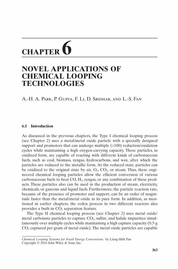
for the volume of the tank walls. Although the hydrogen is stored in pure form, when the weight of the tank is factored in (e.g., 86.3 kg for 4.7 kg of fuel at 204 atm), the gravimetric fuel capacity of high - pressure tanks is approximately 5 wt.%, which is signifi cantly smaller than that of conventional liquid fuels. 3 As shown in Figure 6.1 , the gravimetric and volumetric energy densities of compressed hydrogen gas at 340 atm and 680 atm still are substantially lower than the goals set by the DOE FreedomCAR Partnership. 13 Considering the nonideal behavior of hydrogen gas at high pressure, the increase in pressure beyond 680 atm would not improve signifi cantly the energy content of this storage option. For example, doubling the pressure from 680 atm to 1,360 atm would only increase the volumetric hydrogen gas density by 30%, 12 whereas higher pressure requires a large increase in compression power. At 340 atm, it is estimated that 8.5% of the energy content of the hydrogen would be con-sumed in compression. 14 Unlike conventional tanks for liquid fuels, which can be constructed in different shapes and dimensions to best use the available space, high - pressure tanks for hydrogen storage only can be cylindrical. This also limits the application of compressed gas as a hydrogen storage option. However, compressed hydrogen gas currently is a mature option for vehicular applications, and further research is ongoing for the purpose of cost reduction and lower tank weight design. 13
Another method of storing pure hydrogen is in the liquefi ed form. According to its phase diagram, hydrogen exists as a liquid at below − 253 ° C. 13 Liquid hydrogen has a much higher density than compressed hydrogen with a specifi c volume of 14 L/kg, which signifi cantly reduces the size of the onboard fuel tank. The major issues associated with liquefi ed hydrogen are the energy requirements for liquefaction and the dormancy period. The average energy consumption during liquefaction of hydrogen is 30% of the LHV (lower heating value of hydrogen), which is much greater than the energy for hydro-gen compression to 340 – 680 atm. 13 The dormancy period involves the gradual warming - up of hydrogen in the storage tank and the successive boil - off.
Figure 6.1. Gravimetric and volumetric energy densities of various hydrogen storage. 13

366 NOVEL APPLICATIONS OF CHEMICAL LOOPING TECHNOLOGIES
Research has suggested that for a tank containing 4.6 kg of fuel, approximately 4% of the hydrogen will be boiled off per day. 14,15 Thus, cryogenic tanks with advanced insulation are being developed to overcome the dormancy issues. 16,17 In particular, a high - pressure vessel, lined with aluminum and equipped with a composite outer wrap, a multilayer vacuum insulation, and an outer vacuum vessel, has been tested extensively and implemented in a demonstration vehicle. 16,17 This vehicle can be fueled using either compressed hydrogen gas or liquid hydrogen depending on the desired driving distance. 13
A hybrid hydrogen tank is a relatively new idea consisting of a typical compressed hydrogen tank that is fi lled partially with low - temperature revers-ible hydrogen absorbing alloys. 18 Typical reversible hydrides such as LaNi and FeTi can store hydrogen with volumetric densities of 6.7 – 7.7 L/kg at 100 ° C, which is several times greater than compressed hydrogen 13 in terms of volu-metric density. Because of its high volumetric energy density, this combined storage option can allow more compact hydrogen storage without sacrifi cing the advantages of a compressed hydrogen system.
Compressed, liquefi ed, and hybrid tanks have the major advantage of instantaneously providing pure hydrogen at high rates, whereas other systems involving chemisorption or physisorption of hydrogen require a signifi cant temperature swing to regenerate hydrogen on demand. Refueling also is rela-tively simple and fast because no chemical reactions are involved with the refi lling of compressed and liquefi ed tanks, and the hydrogenation of the hydrides in hybrid tanks is considered to be rapid.
6.2.2 Metal Hydrides
Metal - hydride - based hydrogen storage is not a new technology and has been researched extensively during the past 30 years. Metal hydrides store hydrogen chemically in a crystalline structure that can pack more hydrogen into a given volume than liquid hydrogen. The reversible equilibrium reaction that involves hydrogen storage and regeneration can be written as follows:
MH Heat M Hsolid solidn n, + ↔ + ( )2 2 (6.2.1)
However, because hydrogen is very light and the metals usually are fairly heavy by comparison, the hydrogen storage per unit weight is not as high. Hydrides involving light elements such as Li, Be, B, N, Na, Mg, and Al gener-ally have acceptable hydrogen storage per unit weight; 19 – 26 but for binary hydrides of these elements, the binding energy is too strong to be practical. A high binding energy means that the hydride will only release hydrogen at high temperatures. 24,26 For example, MgH 2 , one of the least stable binary hydrides among the light metals, has a theoretical hydrogen capacity of 7.6 wt.%, but its equilibrium hydrogen pressure only reaches 1 atm at about 300 ° C. 26
AlH 3 is a covalently bonded solid with 10.1 wt.% theoretical hydrogen storage that is actually thermodynamically unstable at room temperature. 11
HYDROGEN STORAGE AND ONBOARD HYDROGEN PRODUCTION 367
Because it is unstable at room temperature, it can release hydrogen at tem-peratures below 100 ° C. No currently known process could produce AlH 3 effi ciently or on a large scale, and this recycling of Al to AlH 3 would have to be done offsite. Many other hydrides exhibit high hydrogen capacities and may have other favorable properties, but they have the same drawback as AlH 3 in that there is no known way to recharge the spent “ fuel ” effi ciently or on a large scale. 19 However, current examples of a few known hydride reactions include hydrolysis of MgH 2 with water to produce Mg(OH) 2 and hydrogen, and catalytic hydrolysis of NaBH 4 (which can be stored as a 25% solution in water) to produce aqueous NaBO 2 and hydrogen as shown in the following chemical reaction 11 :
NaBH H O NaBO H4 2 2 22 4+ → + (6.2.2)
These sorts of hydrides may still fi nd specialty applications where econom-ics are not the primary consideration, but they currently are not suitable for mobile applications. If, however, a simple and effi cient process for regenera-tion of any of these compounds was developed, they could in fact meet the requirements for both volumetric and gravimetric energy density.
A hydride that both can release hydrogen and be regenerated under mild conditions is called a reversible hydride. These hydrides usually have equilibrium hydrogen pressures of 1 atm at mild temperatures ( ∼ 0 – 60 ° C). With the proper catalysts, these hydrides can be generated from their metal alloys at room temperature and high pressure, and will release hydrogen at 1 – 2 atm at higher temperatures (still below 100 ° C). 19 Early reversible metal hydrides include transition metal alloys such as FeTiH 2 and MNi 5 H 6 , where M can be various transition metals. Interestingly enough, the latter compound already is used in Ni – MH rechargeable batteries found in many digital cameras and other electronics. Unfortunately, these alloys typically contain only 1 – 2 wt.% hydrogen and therefore, they are not suitable for mobile applications. 20
For a long time, sodium alanate (NaAlH 4 ) was considered to be in the same category as NaBH 4 and other irreversible hydrides despite having an equilib-rium hydrogen pressure of 1 atm at ∼ 30 ° C. 20 This changed in 1997 when Bogdanovic and Schwickardi reported that NaAlH 4 could be regenerated under relatively mild conditions when doped with certain transition metals. 20 So far, the best results have been obtained using Ti as the dopant. 22 Typical conditions for Ti - catalyzed rehydrogenation are 100 ° C and 100 atm. A balance must be achieved between the kinetics, which become more favorable as the temperature increases, and the thermodynamics, which become less favorable as the temperature increases. NaAlH 4 has a theoretical hydrogen storage capacity of 5.5 wt.%, and a reversible hydrogen storage of up to 5 wt.%. When the weight of the tank itself and the other components of the storage system are accounted for, the total system level capacity is expected to be only 2.5 wt.%. Current research tanks have a capacity of only 1 wt.%. 11
368 NOVEL APPLICATIONS OF CHEMICAL LOOPING TECHNOLOGIES
Other techniques that are worth noting, but are not yet well developed, include lithium imide/lithium amide systems and destabilized mixtures of mul-tiple hydrides. Lithium imide can be hydrogenated to lithium amide with 6.5 wt.% reversible storage at around 250 ° C. 20 Other than the relatively high temperature required, this system also has the drawback of producing small amounts of ammonia, which poison polymer electrolyte membrane (PEM) fuel cells even at trace levels. Destabilized mixtures of hydrides are formed by mixing a high - capacity, stable hydride with a compound that forms a stable intermediate with the hydride ’ s dehydrogenated form. One such mixture is a blend of MgH 2 and LiBH 4 , which has been reported to have 9 wt.% reversible storage capacities, but this is only achieved at a high temperature and with slow kinetics. 20 This particular blend achieves a high capacity, because both components have fairly high hydrogen capacities. Future research may produce more destabilized mixtures with more favorable kinetics and thermodynamics.
6.2.3 Bridged Metal - Organic Frameworks
The recent development of fundamentally new classes of nanoporous materi-als based on metal organic structures has been a signifi cant development in the fi eld of gas storage. 27 Metal - organic frameworks (MOFs) are solids that consist of inorganic groups, usually [ZnO 4 ] 6 + , bonded to linear aromatic car-boxylates that form a robust and highly porous cubic framework. 28 Of particu-lar interest for hydrogen adsorption are the isoreticular MOFs, or IRMOFs, whose surface area and gas adsorption capacities are larger than other micro-porous materials such as zeolites and carbon nanotubes. 29 MOFs are promising candidates for gas storage applications because they can be synthesized at high purity, with high crystallinity, potentially large quantities, and at low cost. Perhaps most importantly, MOFs can have an almost endless variety of struc-tures and functional groups, leading to the possibility of rational design of sorbent materials tailored to specifi c applications. 28
In recent years, IRMOFs by themselves have not produced spectacular results in terms of hydrogen adsorption at room temperature. For example, IRMOF - 1 (or MOF - 5) adsorbed hydrogen up to 4.5 wt.% at 78 K ( − 195 ° C), but only adsorbed 1.0 wt.% at room temperature and 20 bar (2 MPa). 28 When MOFs are mixed with an active - carbon bridge, however, uptake at room tem-perature increased dramatically thanks to a phenomenon known as hydrogen spillover. Hydrogen spillover can be described as the dissociative chemisorp-tion of hydrogen on one site, such as a metal particle, and the subsequent transportation of atomic hydrogen onto another substrate, usually carbon or alumina. 30 In regard to the IRMOF structure, hydrogen rapidly dissociates and bonds to the metal/active carbon catalyst (Pt/AC), but slowly diffuses from the catalyst toward the MOF structure. It has been shown that surface diffu-sion of hydrogen atoms is the rate - determining step in hydrogen spillover. 30 However, in the presence of carbon bridging, a secondary - spillover medium, the overall chemisorption process occurs faster. For example, Li and Yang have

HYDROGEN STORAGE AND ONBOARD HYDROGEN PRODUCTION 369
shown that the uptake of hydrogen onto carbon - bridged IRMOF - 8 at ambient conditions is eight times greater than that of pure IRMOF - 8 under the same conditions, and that the processes are completely reversible/rechargeable at room temperature. 31
Despite continued investigations and research on the kinetics of hydrogen spillover, the kinetics study of surface diffusion of hydrogen atoms under the ambient condition has not been reported. Moreover, the mechanistic details of hydrogen spillover still are not well understood. 30 Thus, future investigation is needed to advance this hydrogen storage concept.
6.2.4 Carbon Nanotubes and Graphite Nanofi bers
Carbon nanotubes (CNTs) generated considerable excitement when initial reports were published showing high storage capacities. Dillon et al. reported initial research on the storage potential of CNTs. 32 They studied the adsorption of hydrogen on soot that contained 0.1 – 0.2 wt.% single - walled nanotubes (SWNTs) and extrapolated their data to determine a hydrogen storage capac-ity of 5 – 10 wt.%. Lee et al. predicted a hydrogen storage capacity of up to 14 wt.% in SWNTs based on theoretical calculations. 33 Multiwalled nanotube (MWNT) capacity was found to vary from 2.7 wt.% to 7.7 wt.%. 33
More recent studies have not been able to achieve the results predicted by Lee et al. 33 Research conducted by Iqbal and Wang 34 found hydrogen adsorp-tion of 2.5 – 3.2 wt.% for SWNTs charged electrochemically. Reversible hydro-gen storage of 1.5 wt.% was achieved with desorption taking place at 70 ° C. Dillon et al. conducted further research on hydrogen adsorption on MWNTs and found that although no hydrogen was adsorbed by clean MWNTs or iron nanoparticles under near - ambient conditions, MWNTs that contained signifi -cant quantities of iron nanoparticles were able to store 0.035 wt.% hydrogen. 32 They concluded that the adsorption characteristics must result from an inter-action between the MWNTs and the iron nanoparticles. Other studies have confi rmed that the presence of metal nanoparticles is essential to hydrogen adsorption in both SWNTs and MWNTs. Most recent studies have found adsorption in the range of 1 – 4 wt.% for SWNTs and lower for MWNTs. 34
Graphite nanofi bers (GNFs) are a nanostructured form of carbon consist-ing of layers of graphite formed into fi bers. The individual layers of graphite may be parallel (tubular), perpendicular (platelet), or at an angle (herring-bone) to the fi ber axis. The length and diameter of individual GNFs can vary depending on many factors, but typical values include lengths of 50 μ m and diameters of 250 nm. 30 GNFs can be formed by several processes, but the most common processes are thermal decomposition of hydrocarbons, typically acet-ylene, ethylene, or benzene, 4,35,36,37 and catalytic graphitization of electrospun polymer fi bers, typically poly(vinylidene fl uoride). 38
The fi rst research on the use of GNFs for hydrogen storage was published in 1998. Initial research done by Chambers et al. 4 achieved hydrogen adsorption varying from 11 wt.% for tubular GNFs to 67 wt.% for herringbone GNFs. Subsequent hydrogen desorption was reported to be as high as 58 wt.%.
370 NOVEL APPLICATIONS OF CHEMICAL LOOPING TECHNOLOGIES
Adsorption took place at room temperature and at pressures ranging from 44 to 112 atm. Desorption took place at room temperature and atmospheric pres-sure. Ahn et al. 36 conducted research on GNFs and other forms of activated carbon and found much lower storage capacities at room temperature and at 77 K ( − 196 ° C). GNFs were found to adsorb approximately the same amount of hydrogen as other forms of activated carbon, with the best capacity being ∼ 1 wt.% at 77 K for GNFs. Fan et al. 37 reported a hydrogen storage capacity of 10 – 13 wt.% for GNFs. More recent research done by Gupta et al. 35 found a hydrogen storage capacity of 17 wt.% for GNFs grown by thermal decom-position of acetylene on Pd sheets. Hong et al. 38 formed GNFs from electros-pun poly(vinylidene fl uoride) nanofi bers and reported a storage capacity of 0.11 – 0.18 wt.%.
GNFs present a very attractive option for hydrogen storage due to their high storage capacity and their ability to both adsorb and desorb hydrogen at room temperature. However, the actual hydrogen storage capacity of these materials varies greatly, and the factors affecting this variance are not yet understood. All studies so far have focused on producing milligram or gram quantities of GNFs, but a commercial system for use in a typical automobile may require anywhere from 3 to 50 kg of GNF per vehicle. No process cur-rently exists for the mass production of GNFs, and it is not known whether such a process could be economical. In addition, the ability of GNFs to with-stand multiple hydrogenation/dehydrogenation cycles is not well understood. One study found that the capacity decreased by 30% after multiple cycles, 37 whereas another study found the capacity actually increased over the fi rst 10 cycles and remained constant thereafter. 35 Although desorption of hydrogen from GNFs is very fast, 4 adsorption takes hours to complete. 4,37
6.2.5 Onboard Hydrogen Production via Iron Based Materials
An onboard hydrogen production process such as one derived from the chemi-cal looping strategy could be an option for the H 2 storage techniques dicussed in the previous sections. When an iron based looping medium is used, this process allows the storage and production of hydrogen onboard a vehicle. This hydrogen storage system is based on the reaction of steam with Fe in order to produce hydrogen as described in the reaction:
3 4 42 3 4 2Fe H O Fe O H+ ↔ + (6.2.3)
Thermodynamics dictates that for stoichiometric conversion of this reac-tion, steam must be made to react with Fe in a countercurrent fashion. This is easily achieved in a series of fi xed bed reactors. TGA experiments show that a temperature above 400 ° C is suffi cient to drive the reaction to completion. Although such an operating temperature is considered to be high relative to aforementioned metal hydride based hydrogen strorage materials, and it requires a large amount of heat input for the hydrogen stored to be released,
HYDROGEN STORAGE AND ONBOARD HYDROGEN PRODUCTION 371
the exothermic nature of the steam iron reaction can potentially minimize the heat input for onboard hydrogen production using iron and steam. ASPEN simulations of Reaction (6.2.3) show that if steam at 300 ° C is made to react with Fe at 25 ° C, the resultant heat of reaction will lead to an adiabatic tem-perature rise to 600 ° C. Hence, if a source of steam is available, Reaction (6.2.3) can potentially be carried out without the need for extra heating devices.
For the system to work, there needs to be a place to generate steam from water. A number of sources of heat may be utilized to achieve this.
Source 1: Hydrogen is produced at high temperatures, but for use in a PEM fuel cell the temperature of the hydrogen needs to be brought down to about 100 ° C. This heat may be used to generate steam.
Source 2: Additionally, more steam may be generated by using the heat from the oxidization of Fe 3 O 4 to Fe 2 O 3 in air.
212
33 4 2 2 3Fe O O Fe O+ → (6.2.4)
Source 3: In case a hydrogen internal combustion engine (ICE) is used, heat can be absorbed from the engine using a suitable coolant (e.g., mineral oil) with a boiling point above 100 ° C to generate steam in a separate heat exchanger. If permitted by the specifi cations of the ICE, water may be directly injected to cool the engine resulting in steam production.
Source 4: The high - grade heat content of the exhaust from a H 2 ICE can be utilized to generate steam on board the vehicle.
Source 5: Use some of the Fe stored on board to react with air. This will allow for the combustion of Fe to Fe 2 O 3 , releasing a large amount of energy. For this purpose, a dedicated fi xed bed can be put into the vehicle for heat generation. Water can be passed through this bed to capture the heat and generate steam.
4 3 22 2 3Fe O Fe O+ → (6.2.5)
Source 6: The fuel cell device utilizing the hydrogen generates a large amount of heat. This heat may be integrated back to generate steam. A PEM fuel cell typically works in the 70 – 150 ° C range. The excess heat may be used to generate low grade steam.
Source 7: The hydrogen produced is put into a storage vessel. This vessel mainly provides hydrogen to the fuel cell, but part of the hydrogen stored may be routed back and combusted to generate heat for produc-ing steam. For initial startup of the vehicle, a dedicated small hydrogen tank may be installed in the vehicle to switch on when the hydrogen storage tank does not have enough hydrogen pressure.
372 NOVEL APPLICATIONS OF CHEMICAL LOOPING TECHNOLOGIES
Source 8: The PEM fuel cell converts only about 90% of the hydrogen input. The remaining hydrogen may be combusted to provide heat for steam.
Source 9: Part of the electricity produced by the fuel cell and stored in the battery may be utilized to electrically heat the water using resistance heating to generate steam.
The water required for H 2 production may be recovered from the fuel cell exhaust in an air - cooled condenser that removes heat by convection into the ambient air when the vehicle is in motion. Greater than 90% of the water necessary is expected to be recovered in this manner. Additionally, in case it is desired, the exhaust may be routed through the air - conditioning system of the vehicle for further condensation, but this may impose an energy penalty on the system.
Once the Fe particles have been oxidized in the vehicle (to Fe 3 O 4 or Fe 2 O 3 as the case may be), they can be reduced back to Fe by utilizing a reaction with fuels:
2 2 3 2 4 2 32 3 2 2x y z x y x y zx y z+ −( )[ ] + → + ( ) + + −( )[ ]Fe O C H O CO H O Fe (6.2.6)
The fuels may be a gaseous fuel like natural gas, producer gas, or syngas, a liquid fuel like gasoline, or a solid fuel like coal, or wood. In the case where Fe 3 O 4 is generated from the vehicle, Reaction (6.2.4) can be carried out fi rst to convert it to Fe 2 O 3 so that the CO 2 generation from Reaction (6.2.6) can be enhanced. This reaction will also help increase the temperature of the particles so that Reaction (6.2.6) can readily proceed.
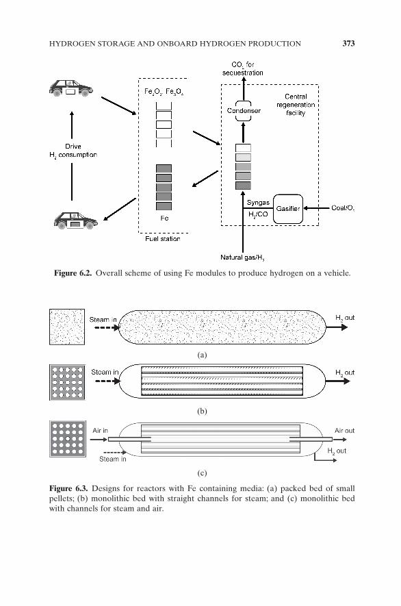
Reaction (6.2.6) will likely need to be conducted outside the vehicle at a central fuel station. Such a centralized station may be built outside a city where the spent particles can be regenerated and distributed to retail outlets. Figure 6.2 shows the overall scheme for using iron to produce hydrogen on a vehicle. The design of the particle regeneration rectors given in the fi gure involves the fl ow of reactive fuel countercurrent to the fl ow of the spent particles as described in Section 4.4.1. The regenerated iron particles exit from the reactor and can be used for producing hydrogen on board the vehicle. The hydrogen generation can be carried out in a packed bed reactor or a monolithic bed reactor as shown in Figure 6.3 . The steam can pass through the reactors at high temperatures and react with iron to form hydrogen. For a packed bed reactor shown in Figure 6.3 (a), the particle formulation can be cast into small pellets of 1 – 5 mm in size. These pellets can be randomly packed into a metallic vessel to establish a packed bed. It is desired that the metallic vessel is of a rectangular cross section for close packing in a module, though circular cross section can also be used. The designs for the monolithic bed reactors are shown in Figures 6.3 (b) and 6.3 (c). The monoliths in the design are of ceramic structures with channels/holes present over the length of the structure. This
HYDROGEN STORAGE AND ONBOARD HYDROGEN PRODUCTION 373
Figure 6.2. Overall scheme of using Fe modules to produce hydrogen on a vehicle.
Figure 6.3. Designs for reactors with Fe containing media: (a) packed bed of small pellets; (b) monolithic bed with straight channels for steam; and (c) monolithic bed with channels for steam and air.
(a)
(b)
(c)

374 NOVEL APPLICATIONS OF CHEMICAL LOOPING TECHNOLOGIES
structure allows the packing of iron particles in a confi ned space. With suitable design on end caps, it is possible to route fl uids through different channels. It also allows air to pass through some channels, while steam fl ows through other channels, as shown in Figure 6.3 (c). This functionality could provide the heat, released from Reactions (6.2.4) and (6.2.5), for generation of steam used for its reaction with iron. In all designs, refractory lining or vacuum jacket could be used to prevent heat losses from the reactors. It is noted that in module design, iron can also be embedded in the ceramic channel wall materials. In this case, both the reduction and regeneration reactions take place directly on the module.
An important aspect of the iron particle regeneration process is that the gaseous products from Reaction (6.2.6) will mainly be steam and CO 2 . After condensation of steam, the CO 2 rich stream can be easily separated and sequestered using the same carbon sequestration techniques intended for stationary power plants. Hence, the process can potentially save the cost for CO 2 capture. Further, since no CO 2 is emitted from the vehicle, the overall scheme provides a viable method for CO 2 emission control when a suitable CO 2 sequestration technique is available.
A number of such reactors may be required for generating an adequate quantity of H 2 for use in a transportation vehicle. Also, if the reactors are connected in series, the H 2 purities obtained can be very high. Such a series reactor assembly forms the key component of a module that can be used for onboard hydrogen production applications. Figures 6.4 , 6.5 and 6.6 present some confi gurations for the modules made up of the reactors shown in Figure 6.3 . The reactors are connected using metallic tubing welded to the end caps. The reactor assembly is enclosed in a suitable metallic box/container with insulation to prevent loss of heat to the surroundings. Depending on the heat integration scheme, the number of fl uid inlet and outlet points may be varied.
Figure 6.4. H 2 production module using a series of fi xed - bed reactors.
In Out Iron fuel module Insulation

HYDROGEN STORAGE AND ONBOARD HYDROGEN PRODUCTION 375
In the simplest scheme, as shown in Figures 6.4 and 6.5 , there are only one inlet (steam) point and one outlet (H 2 ) point. The fl uid fl ow lines can be con-nected to or disconnected from the module using quick - connect couplings. The module can easily be loaded to or unloaded from a transportation vehicle.
Such modules may be directly purchased from a retail store. These may also be sold through “ Iron Stations ” or the “ Fuel Station, ” the future equiva-lent of gas stations, as shown in Figure 6.2 . It is note that even though Reaction (6.2.3) takes place at a temperature above 400 ° C, within the reactors, only the region proximate to where the reaction front is developed will be hot.
Figure 6.5. H 2 production module using a series of monolithic - bed reactors.
In Out Iron fuel moduleInsulation
Figure 6.6. H 2 production module using a series of monolithic - bed reactors with air injection to provide heat for steam formation.
In InOut Out Iron fuel moduleInsulation
Air Steam
376 NOVEL APPLICATIONS OF CHEMICAL LOOPING TECHNOLOGIES
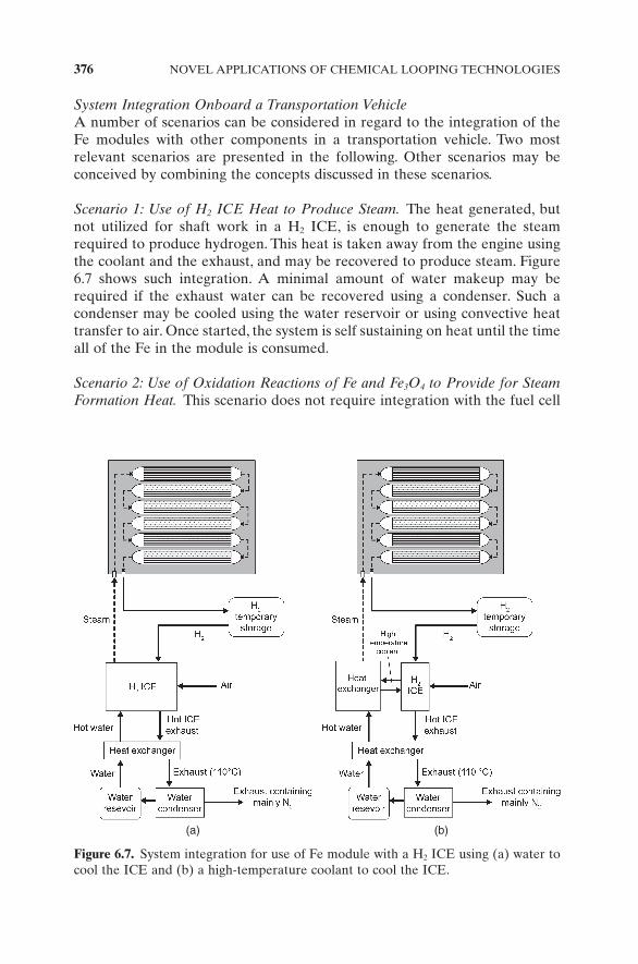
System Integration Onboard a Transportation Vehicle A number of scenarios can be considered in regard to the integration of the Fe modules with other components in a transportation vehicle. Two most relevant scenarios are presented in the following. Other scenarios may be conceived by combining the concepts discussed in these scenarios.
Scenario 1: Use of H 2 ICE Heat to Produce Steam. The heat generated, but not utilized for shaft work in a H 2 ICE, is enough to generate the steam required to produce hydrogen. This heat is taken away from the engine using the coolant and the exhaust, and may be recovered to produce steam. Figure 6.7 shows such integration. A minimal amount of water makeup may be required if the exhaust water can be recovered using a condenser. Such a condenser may be cooled using the water reservoir or using convective heat transfer to air. Once started, the system is self sustaining on heat until the time all of the Fe in the module is consumed.
Scenario 2: Use of Oxidation Reactions of Fe and Fe 3 O 4 to Provide for Steam Formation Heat. This scenario does not require integration with the fuel cell
Figure 6.7. System integration for use of Fe module with a H 2 ICE using (a) water to cool the ICE and (b) a high - temperature coolant to cool the ICE.
(a) (b)

HYDROGEN STORAGE AND ONBOARD HYDROGEN PRODUCTION 377
or the H 2 ICE. Hence, this scenario can be used to provide hydrogen with stand - alone Fe module usage. Air is supplied along with steam into the Fe modules, as shown in Figure 6.8 . This air then oxidizes the Fe/Fe 3 O 4 to Fe 2 O 3 , releasing heat that takes the unreacted Fe particles to reaction temperatures of higher than 400 ° C. The confi guration shown in Figure 6.8 (c) involves fi rst sending air through one packed reactor. Water is then added and being
Figure 6.8. Hydrogen production from a stand - alone Fe module.
(a) (b)
(c)
Iron fuel module Iron fuel module
Iron fuel module
H2O(I) + O2
In H2O(I)
H2O(I) Vent
Out H2
Out airIn air
Air
H2storage
H2storage
378 NOVEL APPLICATIONS OF CHEMICAL LOOPING TECHNOLOGIES
converted to steam. Steam reacts with Fe in the remaining reactors to produce hydrogen. For this operation, one reactor bed in the Fe to Fe 2 O 3 oxidation mode with air is required to produce hydrogen from fi ve Fe reactors.
Meeting DOE Targets The energy density of the Fe composite particles, when fully reduced, is calculated to be up to 1.52 kWh/L or 1.17 kWh/kg of the particles. It is comparable to the DOE 2010 target of 1.5 kWh/L for the volumetric energy density. Since the raw material for producing the composite particle is inexpensive and its synthesis procedure is not elaborate, the cost for this on - board hydrogen production option has the potential to meet the DOE target of $2/kWh set for 2015. The potential challenges to this option, however, include relatively high reaction temperatures and delicate heat integration requirement.
6.3 Carbonation – Calcination Reaction ( CCR ) Process for Carbon Dioxide Capture
As mentioned in Chapter 1 , carbon dioxide capture is the most expensive step of the overall threefold carbon management step, which consists of separation, transportation, and sequestration. The ongoing research and development (R & D) on carbon management includes mapping the strategy for CO 2 separa-tion. Such strategies include improving the energy - intensive low - temperature amine scrubbing process, demonstrating the chilled ammonia process, devel-oping further oxycombustion technology (in which high - purity oxygen is used for combustion), and employing reactive CO 2 separation using dry, solid sor-bents such as limestone, potassium carbonates, lithium silicates, and sodium carbonates, which yield a sequestration - ready CO 2 gas stream upon decompo-sition. 39 Other processes being investigated include low - temperature pressure swing adsorption processes using hydrotalcite. 40 Thus, cost - effective carbon - capture technologies play an important role in CO 2 mitigation for current plant operation. In a typical fl ue gas stream (dry basis) generated from coal combustion power plants, the concentration of CO 2 is low, representing approximately 15% of the fl ue gas stream. Low CO 2 partial pressures, com-bined with the extremely high fl ue gas generation rate, make CO 2 capture from PC power plants an energy - intensive step. An ideal CO 2 capture technol-ogy would incorporate effective process integration schemes to minimize the parasitic energy required for CO 2 separation.
One process alternative uses a calcium - based solid sorbent at a high tem-perature to capture CO 2 and SO 2 simultaneously. The CCR Process, which is an outgrowth of two other processes developed at The Ohio State University: the Ohio State Carbonation Ash Reactivation (OSCAR) Process 41 and the Calcium - Based Reaction Separation for CO 2 (CaRS – CO 2 ) Process, 42 uses calcium oxide to react with the CO 2 and SO 2 present in the fl ue gas stream at

CARBONATION–CALCINATION REACTION (CCR) PROCESS 379
a high temperature (450 – 750 ° C). Similar to the Calcium Looping Process for hydrogen production described in Chapter 4 , the calcium oxide can be derived from multiple sources including hydrated lime, natural limestone, or reengi-neered calcium carbonate, such as Precipitated Calcium Carbonate (PCC) (see Chapter 2 ). 43,44
The concept of capturing and separating CO 2 from fl ue gas using limestone - based sorbents is depicted in Figure 6.9 . The fl ue gas comes into contact with calcium oxide (CaO), which reacts with the CO 2 and SO 2 in the fl ue gas to form calcium carbonate (CaCO 3 ) and calcium sulfate (CaSO 4 ). During the carbonation and sulfation reactions, which typically take place between 600 ° C and 700 ° C, heat is released. The reacted sorbent is regenerated in a separate step by decomposing CaCO 3 at higher temperatures (greater than 850 ° C) to yield CaO and CO 2 . The thermal stability of calcium sulfate ensures that it does not decompose and remains as calcium sulfate. By calcining the sorbent in a proper environment (see Chapter 2 ), the degeneration of the reactivity of regenerated calcium sorbent can be minimized while yielding a pure or con-centrated gas stream of CO 2 that can be compressed and transported for sequestration. The process thus can take a fl ue gas that contains typically 10 – 15% CO 2 and convert it into a nearly pure ( > 90%) CO 2 stream.
Reactions (6.3.1) and (6.3.2) summarize the basic chemistry involved in the process:
Carbonation: CaO s CO g CaCO s kJ mol( ) + ( ) → ( ) = −2 3 178ΔH (6.3.1)
Calcination: CaCO s CaO s CO g kJ mol3 2 178( ) → ( ) + ( ) = +ΔH (6.3.2)
As shown here, the carbonation process is exothermic, whereas calcination requires heat input. The heat integration is thus essential, in that the heat released at temperatures of 600 – 700 ° C during the carbonation process needs to be recovered and used, whereas additional heat energy is necessary for the calcination reaction.
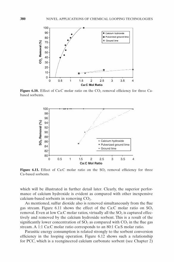
Sorbent reactivity has a signifi cant effect on the CO 2 removal effi ciency. Therefore, the type of sorbent has a considerable effect on the overall CO 2 removal, as shown in Figure 6.10 . The data were obtained from an entrained bed reactor using a fl ue gas stream generated by coal combustion at 9 kg/h,
Figure 6.9. The carbonation – calcination – reaction - based CO 2 capture process.
380 NOVEL APPLICATIONS OF CHEMICAL LOOPING TECHNOLOGIES
which will be illustrated in further detail later. Clearly, the superior perfor-mance of calcium hydroxide is evident as compared with other inexpensive calcium - based sorbents in removing CO 2 .
As mentioned, sulfur dioxide also is removed simultaneously from the fl ue gas stream. Figure 6.11 shows the effect of the Ca:C molar ratio on SO 2 removal. Even at low Ca:C molar ratios, virtually all the SO 2 is captured effec-tively and removed by the calcium hydroxide sorbent. This is a result of the signifi cantly lower concentration of SO 2 as compared with CO 2 in the fl ue gas stream. A 1:1 Ca:C molar ratio corresponds to an 80:1 Ca:S molar ratio.
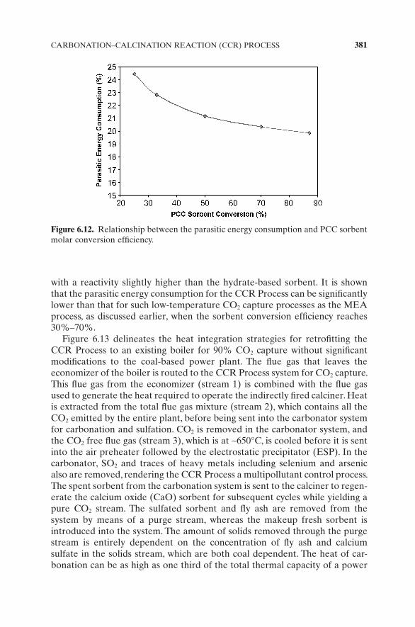
Parasitic energy consumption is related strongly to the sorbent conversion effi ciency in the looping operation. Figure 6.12 shows such a relationship for PCC, which is a reengineered calcium carbonate sorbent (see Chapter 2 )
Figure 6.10. Effect of Ca:C molar ratio on the CO 2 removal effi ciency for three Ca - based sorbents.
Figure 6.11. Effect of Ca:C molar ratio on the SO 2 removal effi ciency for three Ca - based sorbents.
100
98
96
94
92
90
88
86
84
82
80
SO
2 R
emov
al (
%)
0 0.5 1 1.5 2 2.5 3 3.5 4Ca:C Mol Ratio
Calcium hydroxidePulverized ground limeGround lime
CARBONATION–CALCINATION REACTION (CCR) PROCESS 381
with a reactivity slightly higher than the hydrate - based sorbent. It is shown that the parasitic energy consumption for the CCR Process can be signifi cantly lower than that for such low - temperature CO 2 capture processes as the MEA process, as discussed earlier, when the sorbent conversion effi ciency reaches 30% – 70%.
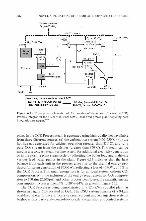
Figure 6.13 delineates the heat integration strategies for retrofi tting the CCR Process to an existing boiler for 90% CO 2 capture without signifi cant modifi cations to the coal - based power plant. The fl ue gas that leaves the economizer of the boiler is routed to the CCR Process system for CO 2 capture. This fl ue gas from the economizer (stream 1) is combined with the fl ue gas used to generate the heat required to operate the indirectly fi red calciner. Heat is extracted from the total fl ue gas mixture (stream 2), which contains all the CO 2 emitted by the entire plant, before being sent into the carbonator system for carbonation and sulfation. CO 2 is removed in the carbonator system, and the CO 2 free fl ue gas (stream 3), which is at ∼ 650 ° C, is cooled before it is sent into the air preheater followed by the electrostatic precipitator (ESP). In the carbonator, SO 2 and traces of heavy metals including selenium and arsenic also are removed, rendering the CCR Process a multipollutant control process. The spent sorbent from the carbonation system is sent to the calciner to regen-erate the calcium oxide (CaO) sorbent for subsequent cycles while yielding a pure CO 2 stream. The sulfated sorbent and fl y ash are removed from the system by means of a purge stream, whereas the makeup fresh sorbent is introduced into the system. The amount of solids removed through the purge stream is entirely dependent on the concentration of fl y ash and calcium sulfate in the solids stream, which are both coal dependent. The heat of car-bonation can be as high as one third of the total thermal capacity of a power
Figure 6.12. Relationship between the parasitic energy consumption and PCC sorbent molar conversion effi ciency.
382 NOVEL APPLICATIONS OF CHEMICAL LOOPING TECHNOLOGIES
plant. In the CCR Process, steam is generated using high - quality heat available from three different sources: (a) the carbonation system (450 – 750 ° C), (b) the hot fl ue gas generated for calciner operation (greater than 850 ° C), and (c) a pure CO 2 stream from the calciner (greater than 850 ° C). This steam can be used in a secondary steam turbine system for additional electricity generation or in the existing plant steam cycle by offsetting the boiler load and in driving various feed water pumps in the plant. Figure 6.13 indicates that the heat balance from each unit in the process gives rise to the thermal energy pro-duced for steam generation of 855 MW th , refl ecting a loss of 45 MW th or 5% in the CCR Process. This small energy loss is for an ideal system without CO 2 compression. With the inclusion of the energy requirement for CO 2 compres-sion to 150 atm (2,200 psi) and other process heat losses, the parasitic energy consumption increases from 5% to 20% – 24%, as given in Figure 6.12 .
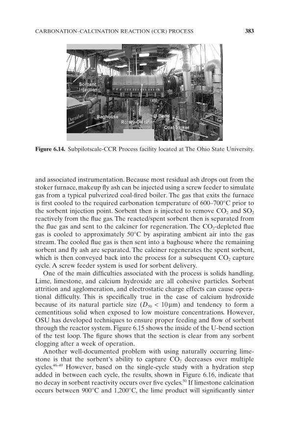
The CCR Process is being demonstrated in a 120 - KW th subpilot plant, as shown in Figure 6.14 , located at OSU. The OSU system consists of a 9 - kg/h coal - fi red stoker furnace, a rotary calciner, sorbent and ash injection systems, baghouse, fans, particulate control devices, data acquisition and control systems,
Figure 6.13. Conceptual schematic of Carbonation – Calcination Reaction (CCR) Process integration for a 300 - MW e (900 - MW th ) coal - fi red power plant depicting heat integration strategies. 42,45
CARBONATION–CALCINATION REACTION (CCR) PROCESS 383
and associated instrumentation. Because most residual ash drops out from the stoker furnace, makeup fl y ash can be injected using a screw feeder to simulate gas from a typical pulverized coal - fi red boiler. The gas that exits the furnace is fi rst cooled to the required carbonation temperature of 600 – 700 ° C prior to the sorbent injection point. Sorbent then is injected to remove CO 2 and SO 2 reactively from the fl ue gas. The reacted/spent sorbent then is separated from the fl ue gas and sent to the calciner for regeneration. The CO 2 - depleted fl ue gas is cooled to approximately 50 ° C by aspirating ambient air into the gas stream. The cooled fl ue gas is then sent into a baghouse where the remaining sorbent and fl y ash are separated. The calciner regenerates the spent sorbent, which is then conveyed back into the process for a subsequent CO 2 capture cycle. A screw feeder system is used for sorbent delivery.
One of the main diffi culties associated with the process is solids handling. Lime, limestone, and calcium hydroxide are all cohesive particles. Sorbent attrition and agglomeration, and electrostatic charge effects can cause opera-tional diffi culty. This is specifi cally true in the case of calcium hydroxide because of its natural particle size ( D 50 < 10 μ m) and tendency to form a cementitious solid when exposed to low moisture concentrations. However, OSU has developed techniques to ensure proper feeding and fl ow of sorbent through the reactor system. Figure 6.15 shows the inside of the U - bend section of the test loop. The fi gure shows that the section is clear from any sorbent clogging after a week of operation.
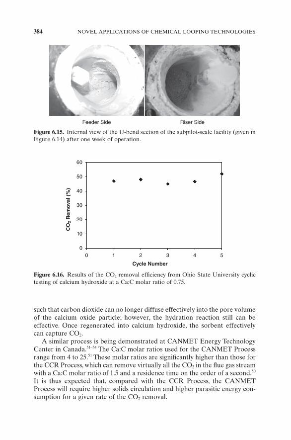
Another well - documented problem with using naturally occurring lime-stone is that the sorbent ’ s ability to capture CO 2 decreases over multiple cycles. 46 – 49 However, based on the single - cycle study with a hydration step added in between each cycle, the results, shown in Figure 6.16 , indicate that no decay in sorbent reactivity occurs over fi ve cycles. 50 If limestone calcination occurs between 900 ° C and 1,200 ° C, the lime product will signifi cantly sinter
Figure 6.14. Subpilotscale - CCR Process facility located at The Ohio State University.
384 NOVEL APPLICATIONS OF CHEMICAL LOOPING TECHNOLOGIES
such that carbon dioxide can no longer diffuse effectively into the pore volume of the calcium oxide particle; however, the hydration reaction still can be effective. Once regenerated into calcium hydroxide, the sorbent effectively can capture CO 2 .
A similar process is being demonstrated at CANMET Energy Technology Center in Canada. 51 – 54 The Ca:C molar ratios used for the CANMET Process range from 4 to 25. 51 These molar ratios are signifi cantly higher than those for the CCR Process, which can remove virtually all the CO 2 in the fl ue gas stream with a Ca:C molar ratio of 1.5 and a residence time on the order of a second. 50 It is thus expected that, compared with the CCR Process, the CANMET Process will require higher solids circulation and higher parasitic energy con-sumption for a given rate of the CO 2 removal.
Figure 6.16. Results of the CO 2 removal effi ciency from Ohio State University cyclic testing of calcium hydroxide at a Ca:C molar ratio of 0.75.
60
50
40
30
20
10
0
CO
2 R
emov
al (
%)
0 1 2 3 4 5
Cycle Number
Figure 6.15. Internal view of the U - bend section of the subpilot - scale facility (given in Figure 6.14 ) after one week of operation.
Feeder Side Riser Side
CHEMICAL LOOPING GASIFICATION INTEGRATED WITH FUEL CELLS 385
6.4 Chemical Looping Gasifi cation Integrated with Fuel Cells
The high effi ciencies and fl exibility to produce desired products, coupled with the integrated environmental benefi ts in terms of a readily sequestrable CO 2 stream, make chemical looping gasifi cation of coal an attractive technology for energy conversion and management. 55 – 58 As discussed in Chapter 5 , the Coal - Direct Chemical Looping (CDCL) Process is very attractive because it is capable of converting as much as 80% of the thermal energy of coal into hydrogen. Here, energy conversion schemes that effectively extract chemical energy from the fuels are proposed by integrating the fuel cell with chemical looping.
6.4.1 Chemical Looping Gasifi cation Integrated with Solid - Oxide Fuel Cells
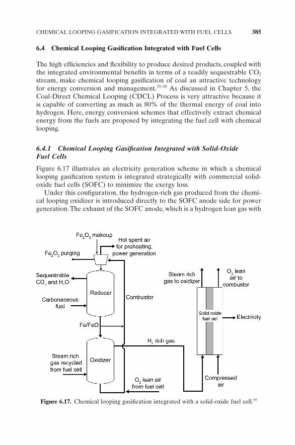
Figure 6.17 illustrates an electricity generation scheme in which a chemical looping gasifi cation system is integrated strategically with commercial solid - oxide fuel cells (SOFC) to minimize the exergy loss.
Under this confi guration, the hydrogen - rich gas produced from the chemi-cal looping oxidizer is introduced directly to the SOFC anode side for power generation. The exhaust of the SOFC anode, which is a hydrogen lean gas with
Figure 6.17. Chemical looping gasifi cation integrated with a solid - oxide fuel cell. 59
386 NOVEL APPLICATIONS OF CHEMICAL LOOPING TECHNOLOGIES
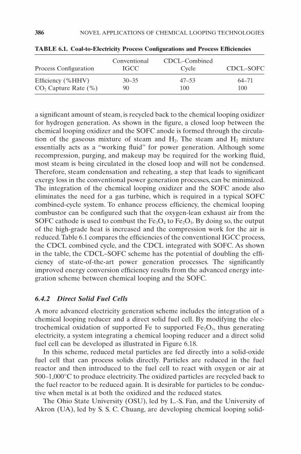
a signifi cant amount of steam, is recycled back to the chemical looping oxidizer for hydrogen generation. As shown in the fi gure, a closed loop between the chemical looping oxidizer and the SOFC anode is formed through the circula-tion of the gaseous mixture of steam and H 2 . The steam and H 2 mixture essentially acts as a “ working fl uid ” for power generation. Although some recompression, purging, and makeup may be required for the working fl uid, most steam is being circulated in the closed loop and will not be condensed. Therefore, steam condensation and reheating, a step that leads to signifi cant exergy loss in the conventional power generation processes, can be minimized. The integration of the chemical looping oxidizer and the SOFC anode also eliminates the need for a gas turbine, which is required in a typical SOFC combined - cycle system. To enhance process effi ciency, the chemical looping combustor can be confi gured such that the oxygen - lean exhaust air from the SOFC cathode is used to combust the Fe 3 O 4 to Fe 2 O 3 . By doing so, the output of the high - grade heat is increased and the compression work for the air is reduced. Table 6.1 compares the effi ciencies of the conventional IGCC process, the CDCL combined cycle, and the CDCL integrated with SOFC. As shown in the table, the CDCL – SOFC scheme has the potential of doubling the effi -ciency of state - of - the - art power generation processes. The signifi cantly improved energy conversion effi ciency results from the advanced energy inte-gration scheme between chemical looping and the SOFC.
6.4.2 Direct Solid Fuel Cells
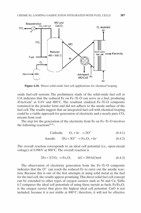
A more advanced electricity generation scheme includes the integration of a chemical looping reducer and a direct solid fuel cell. By modifying the elec-trochemical oxidation of supported Fe to supported Fe 2 O 3 , thus generating electricity, a system integrating a chemical looping reducer and a direct solid fuel cell can be developed as illustrated in Figure 6.18 .
In this scheme, reduced metal particles are fed directly into a solid - oxide fuel cell that can process solids directly. Particles are reduced in the fuel reactor and then introduced to the fuel cell to react with oxygen or air at 500 – 1,000 ° C to produce electricity. The oxidized particles are recycled back to the fuel reactor to be reduced again. It is desirable for particles to be conduc-tive when metal is at both the oxidized and the reduced states.
The Ohio State University (OSU), led by L. - S. Fan, and the University of Akron (UA), led by S. S. C. Chuang, are developing chemical looping solid -
TABLE 6.1. Coal - to - Electricity Process Confi gurations and Process Effi ciencies
Process Confi guration Conventional
IGCC CDCL – Combined
Cycle CDCL – SOFC
Effi ciency (%HHV) 30 – 35 47 – 53 64 – 71 CO 2 Capture Rate (%) 90 100 100
CHEMICAL LOOPING GASIFICATION INTEGRATED WITH FUEL CELLS 387
oxide fuel - cell systems. The preliminary study of the solid - oxide fuel cell at UA indicates that the reduced Fe on Fe – Ti – O can serve as a fuel, producing 45 mA/cm 2 at 0.4 V and 800 ° C. The resultant oxidized Fe – Ti – O composite remained in the powder form and did not adhere to the anode surface of the fuel cell. The results suggest that an integrated fuel cell with chemical looping could be a viable approach for generation of electricity and a nearly pure CO 2 stream from coal.
The step for the generation of the electricity from Fe on Fe – Ti – O involves the following reactions 60,61 :
Cathodic O O224 2+ →− −e (6.4.1)
Anodic Fe O Fe O2 3 622 3+ → +− −e (6.4.2)
The overall reaction corresponds to an ideal cell potential (i.e., open - circuit voltage) of 0.996 V at 800 ° C. The overall reaction is
2 2 3842 2 3Fe 3 O Fe O kJ mol+ → =ΔG (6.4.3)
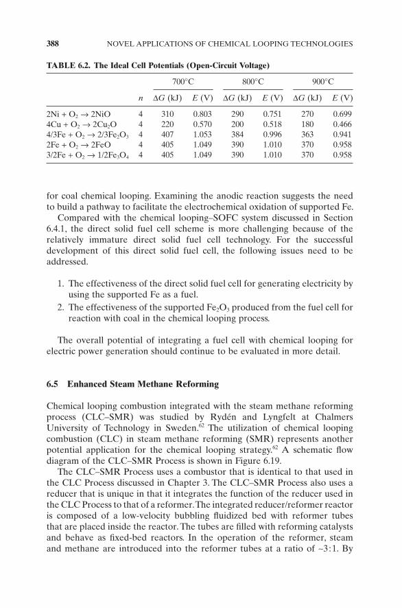
The observation of electricity generation from the Fe – Ti – O composite indicates that the O 2 − can reach the reduced Fe to carry out the anodic reac-tion. Because this is one of the fi rst attempts at using solid metal as the fuel for the fuel cell, the results appear promising. This direct solid fuel cell concept can be extended to other types of oxygen carriers such as Ni and Cu. Table 6.2 compares the ideal cell potentials of using these metals as fuels. Fe/Fe 2 O 3 is the oxygen carrier that gives the highest ideal cell potential. CuO is not included, because it is not stable at 800 ° C; therefore, it will not be effective
Figure 6.18. Direct solid - oxide fuel cell applications for chemical looping.
388 NOVEL APPLICATIONS OF CHEMICAL LOOPING TECHNOLOGIES
for coal chemical looping. Examining the anodic reaction suggests the need to build a pathway to facilitate the electrochemical oxidation of supported Fe.
Compared with the chemical looping – SOFC system discussed in Section 6.4.1 , the direct solid fuel cell scheme is more challenging because of the relatively immature direct solid fuel cell technology. For the successful development of this direct solid fuel cell, the following issues need to be addressed.
1. The effectiveness of the direct solid fuel cell for generating electricity by using the supported Fe as a fuel.
2. The effectiveness of the supported Fe 2 O 3 produced from the fuel cell for reaction with coal in the chemical looping process.
The overall potential of integrating a fuel cell with chemical looping for electric power generation should continue to be evaluated in more detail.
6.5 Enhanced Steam Methane Reforming
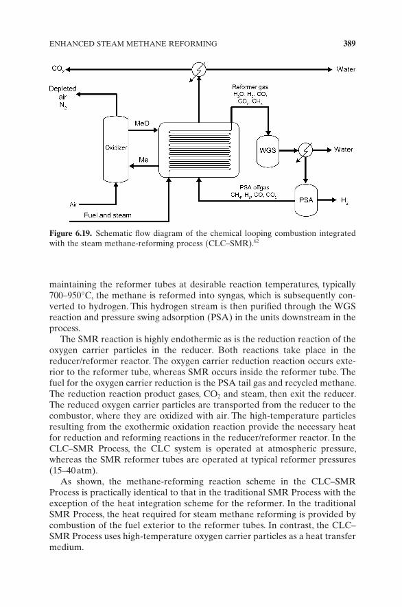
Chemical looping combustion integrated with the steam methane reforming process (CLC – SMR) was studied by Ryd é n and Lyngfelt at Chalmers University of Technology in Sweden. 62 The utilization of chemical looping combustion (CLC) in steam methane reforming (SMR) represents another potential application for the chemical looping strategy. 62 A schematic fl ow diagram of the CLC – SMR Process is shown in Figure 6.19 .
The CLC – SMR Process uses a combustor that is identical to that used in the CLC Process discussed in Chapter 3 . The CLC – SMR Process also uses a reducer that is unique in that it integrates the function of the reducer used in the CLC Process to that of a reformer. The integrated reducer/reformer reactor is composed of a low - velocity bubbling fl uidized bed with reformer tubes that are placed inside the reactor. The tubes are fi lled with reforming catalysts and behave as fi xed - bed reactors. In the operation of the reformer, steam and methane are introduced into the reformer tubes at a ratio of ∼ 3 :1. By
TABLE 6.2. The Ideal Cell Potentials (Open - Circuit Voltage)
n
700 ° C 800 ° C 900 ° C
Δ G (kJ) E (V) Δ G (kJ) E (V) Δ G (kJ) E (V)
2Ni + O 2 → 2NiO 4 310 0.803 290 0.751 270 0.699 4Cu + O 2 → 2Cu 2 O 4 220 0.570 200 0.518 180 0.466 4/3Fe + O 2 → 2/3Fe 2 O 3 4 407 1.053 384 0.996 363 0.941 2Fe + O 2 → 2FeO 4 405 1.049 390 1.010 370 0.958 3/2Fe + O 2 → 1/2Fe 3 O 4 4 405 1.049 390 1.010 370 0.958
ENHANCED STEAM METHANE REFORMING 389
maintaining the reformer tubes at desirable reaction temperatures, typically 700 – 950 ° C, the methane is reformed into syngas, which is subsequently con-verted to hydrogen. This hydrogen stream is then purifi ed through the WGS reaction and pressure swing adsorption (PSA) in the units downstream in the process.
The SMR reaction is highly endothermic as is the reduction reaction of the oxygen carrier particles in the reducer. Both reactions take place in the reducer/reformer reactor. The oxygen carrier reduction reaction occurs exte-rior to the reformer tube, whereas SMR occurs inside the reformer tube. The fuel for the oxygen carrier reduction is the PSA tail gas and recycled methane. The reduction reaction product gases, CO 2 and steam, then exit the reducer. The reduced oxygen carrier particles are transported from the reducer to the combustor, where they are oxidized with air. The high - temperature particles resulting from the exothermic oxidation reaction provide the necessary heat for reduction and reforming reactions in the reducer/reformer reactor. In the CLC – SMR Process, the CLC system is operated at atmospheric pressure, whereas the SMR reformer tubes are operated at typical reformer pressures (15 – 40 atm).
As shown, the methane - reforming reaction scheme in the CLC – SMR Process is practically identical to that in the traditional SMR Process with the exception of the heat integration scheme for the reformer. In the traditional SMR Process, the heat required for steam methane reforming is provided by combustion of the fuel exterior to the reformer tubes. In contrast, the CLC – SMR Process uses high - temperature oxygen carrier particles as a heat transfer medium.
Figure 6.19. Schematic fl ow diagram of the chemical looping combustion integrated with the steam methane - reforming process (CLC – SMR). 62
390 NOVEL APPLICATIONS OF CHEMICAL LOOPING TECHNOLOGIES
To date, the studies on this novel scheme have been limited to theoretical analysis such as heat and mass balances. Experimental testing results are not yet available. Theoretical analysis indicates that the CLC – SMR Process has the potential to achieve a higher H 2 yield than the conventional SMR Process. Therefore, it offers a viable approach for an innovative reforming operation. Some challenges, however, still exist for this process as illustrated below.
1. Approximately 70% of the methane is reformed and converted to H 2 and CO 2 in the WGS reactors. Thus, most of the carbon in this process is separated by the traditional methods such as PSA rather than CLC. Although all of the carbon in the feedstock exits from the reducer/reformer, the CLC system is used to separate only approximately 30% of the total carbon in this process. Thus, the energy savings through carbon capture using the CLC system may not be signifi cant.
2. Both the SMR reaction and the oxygen carrier particle reduction reac-tion, when nickel - or iron - based oxygen carriers are used, are highly endothermic. Thus, the heat required in the integrated reducer/reformer reactor will even be higher than that required in the traditional SMR reformer. The large heat requirement renders the heat integration in the CLC – SMR Process a challenging task.
3. Because high - temperature oxygen carrier particles are the sole heat carrier in the integrated reducer/reformer reactor, there will be a large solids circulation rate and likely a large temperature difference between the combustor and the reducer/reformer. An estimated solids circulation rate of 6,700 t/h for a 300 - MW th CLC – SMR Process indicates a signifi cant solid fl ow rate issue.
4. Heat transfer using fl uidized oxygen carrier particles could pose an increased erosion problem on the reformer tubes.
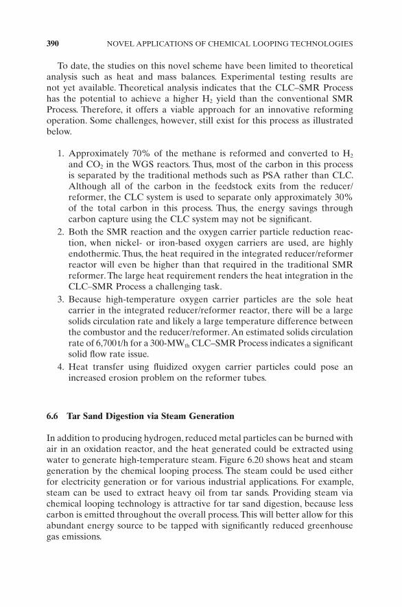
6.6 Tar Sand Digestion via Steam Generation
In addition to producing hydrogen, reduced metal particles can be burned with air in an oxidation reactor, and the heat generated could be extracted using water to generate high - temperature steam. Figure 6.20 shows heat and steam generation by the chemical looping process. The steam could be used either for electricity generation or for various industrial applications. For example, steam can be used to extract heavy oil from tar sands. Providing steam via chemical looping technology is attractive for tar sand digestion, because less carbon is emitted throughout the overall process. This will better allow for this abundant energy source to be tapped with signifi cantly reduced greenhouse gas emissions.
LIQUID FUEL PRODUCTION FROM CHEMICAL LOOPING GASIFICATION 391
6.7 Liquid Fuel Production from Chemical Looping Gasifi cation
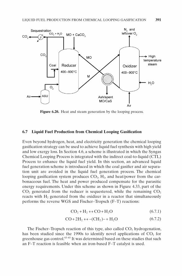
Even beyond hydrogen, heat, and electricity generation the chemical looping gasifi cation strategy can be used to achieve liquid fuel synthesis with high yield and low exergy loss. In Section 4.6 , a scheme is illustrated in which the Syngas Chemical Looping Process is integrated with the indirect coal - to - liquid (CTL) Process to enhance the liquid fuel yield. In this section, an advanced liquid fuel generation scheme is introduced in which the coal gasifi er and air separa-tion unit are avoided in the liquid fuel generation process. The chemical looping gasifi cation system produces CO 2 , H 2 , and heat/power from the car-bonaceous fuel. The heat and power produced compensate for the parasitic energy requirements. Under this scheme as shown in Figure 4.33 , part of the CO 2 generated from the reducer is sequestered, while the remaining CO 2 reacts with H 2 generated from the oxidizer in a reactor that simultaneously performs the reverse WGS and Fischer – Tropsch (F – T) reactions:
CO H CO H O2 2 2+ ↔ + (6.7.1)
CO H CH H O+ ↔ −( )− +2 2 2 2 (6.7.2)
The Fischer – Tropsch reaction of this type, also called CO 2 hydrogenation, has been studied since the 1990s to identify novel applications of CO 2 for greenhouse gas control. 63 – 65 It was determined based on these studies that such an F – T reaction is feasible when an iron - based F – T catalyst is used.
Figure 6.20. Heat and steam generation by the looping process.
392 NOVEL APPLICATIONS OF CHEMICAL LOOPING TECHNOLOGIES
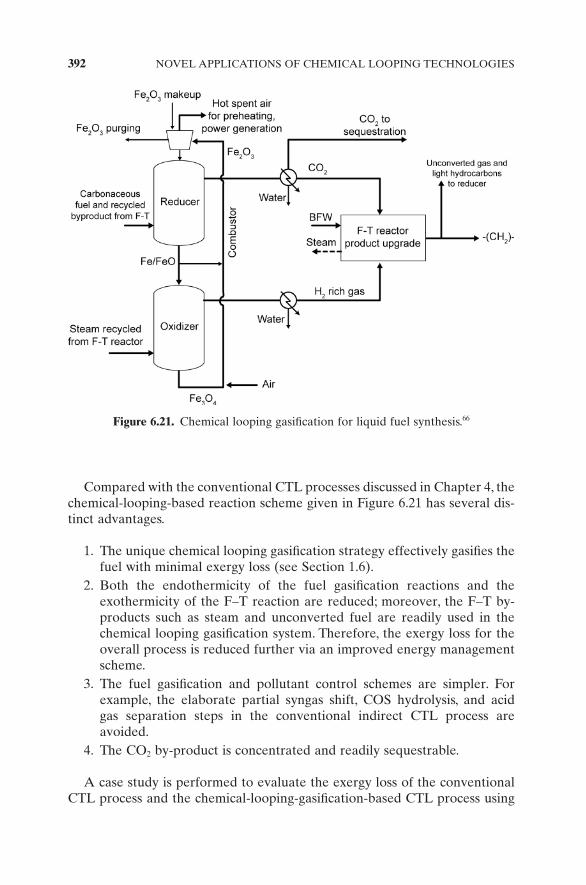
Compared with the conventional CTL processes discussed in Chapter 4 , the chemical - looping - based reaction scheme given in Figure 6.21 has several dis-tinct advantages.
1. The unique chemical looping gasifi cation strategy effectively gasifi es the fuel with minimal exergy loss (see Section 1.6 ).
2. Both the endothermicity of the fuel gasifi cation reactions and the exothermicity of the F – T reaction are reduced; moreover, the F – T by - products such as steam and unconverted fuel are readily used in the chemical looping gasifi cation system. Therefore, the exergy loss for the overall process is reduced further via an improved energy management scheme.
3. The fuel gasifi cation and pollutant control schemes are simpler. For example, the elaborate partial syngas shift, COS hydrolysis, and acid gas separation steps in the conventional indirect CTL process are avoided.
4. The CO 2 by - product is concentrated and readily sequestrable.
A case study is performed to evaluate the exergy loss of the conventional CTL process and the chemical - looping - gasifi cation - based CTL process using
Figure 6.21. Chemical looping gasifi cation for liquid fuel synthesis. 66
CHEMICAL LOOPING WITH OXYGEN UNCOUPLING (CLOU) 393
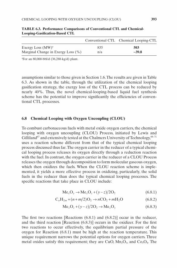
assumptions similar to those given in Section 1.6 . The results are given in Table 6.3 . As shown in the table, through the utilization of the chemical looping gasifi cation strategy, the exergy loss of the CTL process can be reduced by nearly 40%. Thus, the novel chemical - looping - based liquid fuel synthesis scheme has the potential to improve signifi cantly the effi ciencies of conven-tional CTL processes.
6.8 Chemical Looping with Oxygen Uncoupling ( CLOU )
To combust carbonaceous fuels with metal oxide oxygen carriers, the chemical looping with oxygen uncoupling (CLOU) Process, initiated by Lewis and Gilliland 67 and extensively tested at the Chalmers University of Technology, 68 – 71 uses a reaction scheme different from that of the typical chemical looping process discussed thus far. The oxygen carrier in the reducer of a typical chemi-cal looping process releases its oxygen directly through a reduction reaction with the fuel. In contrast, the oxygen carrier in the reducer of a CLOU Process releases the oxygen through decomposition to form molecular gaseous oxygen, which then oxidizes the fuels. When the CLOU reaction scheme is imple-mented, it yields a more effective process in oxidizing, particularly, the solid fuels in the reducer than does the typical chemical looping processes. The specifi c reactions that take place in CLOU include:
Me O Me O Ox y x z y z→ + −( ) 2 2 (6.8.1)
C H O CO H On m n m n m2 2 2 22+ +( ) → + (6.8.2)
Me O O Me Ox z x yy z+ −( ) →2 2 (6.8.3)
The fi rst two reactions [Reactions (6.8.1) and (6.8.2)] occur in the reducer, and the third reaction [Reaction (6.8.3)] occurs in the oxidizer. For the fi rst two reactions to occur effectively, the equilibrium partial pressure of the oxygen for Reaction (6.8.1) must be high at the reaction temperature. This unique requirement narrows the potential options for oxygen carriers. Three metal oxides satisfy this requirement; they are CuO, Mn 2 O 3 , and Co 3 O 4 . The
TABLE 6.3. Performance Comparisons of Conventional CTL and Chemical - Looping - Gasifi cation - Based CTL
Conventional CTL Chemical Looping - CTL
Exergy Loss (MW) a 835 503 Marginal Change in Exergy Loss (%) n/a − 39.8
a For an 80,000 - bbl/d (36,288 - kg/d) plant.
394 NOVEL APPLICATIONS OF CHEMICAL LOOPING TECHNOLOGIES
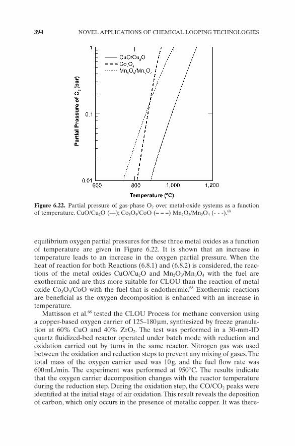
equilibrium oxygen partial pressures for these three metal oxides as a function of temperature are given in Figure 6.22 . It is shown that an increase in temperature leads to an increase in the oxygen partial pressure. When the heat of reaction for both Reactions (6.8.1) and (6.8.2) is considered, the reac-tions of the metal oxides CuO/Cu 2 O and Mn 2 O 3 /Mn 3 O 4 with the fuel are exothermic and are thus more suitable for CLOU than the reaction of metal oxide Co 3 O 4 /CoO with the fuel that is endothermic. 68 Exothermic reactions are benefi cial as the oxygen decomposition is enhanced with an increase in temperature.
Mattisson et al. 68 tested the CLOU Process for methane conversion using a copper - based oxygen carrier of 125 – 180 μ m, synthesized by freeze granula-tion at 60% CuO and 40% ZrO 2 . The test was performed in a 30 - mm - ID quartz fl uidized - bed reactor operated under batch mode with reduction and oxidation carried out by turns in the same reactor. Nitrogen gas was used between the oxidation and reduction steps to prevent any mixing of gases. The total mass of the oxygen carrier used was 10 g, and the fuel fl ow rate was 600 mL/min. The experiment was performed at 950 ° C. The results indicate that the oxygen carrier decomposition changes with the reactor temperature during the reduction step. During the oxidation step, the CO/CO 2 peaks were identifi ed at the initial stage of air oxidation. This result reveals the deposition of carbon, which only occurs in the presence of metallic copper. It was there-
Figure 6.22. Partial pressure of gas - phase O 2 over metal - oxide systems as a function of temperature. CuO/Cu 2 O ( — ); Co 3 O 4 /CoO ( – – – ) Mn 2 O 3 /Mn 3 O 4 ( - - - ). 68
CHEMICAL LOOPING WITH OXYGEN UNCOUPLING (CLOU) 395
fore concluded that the CuO - based oxygen carrier was reduced to metallic copper during the reduction step.
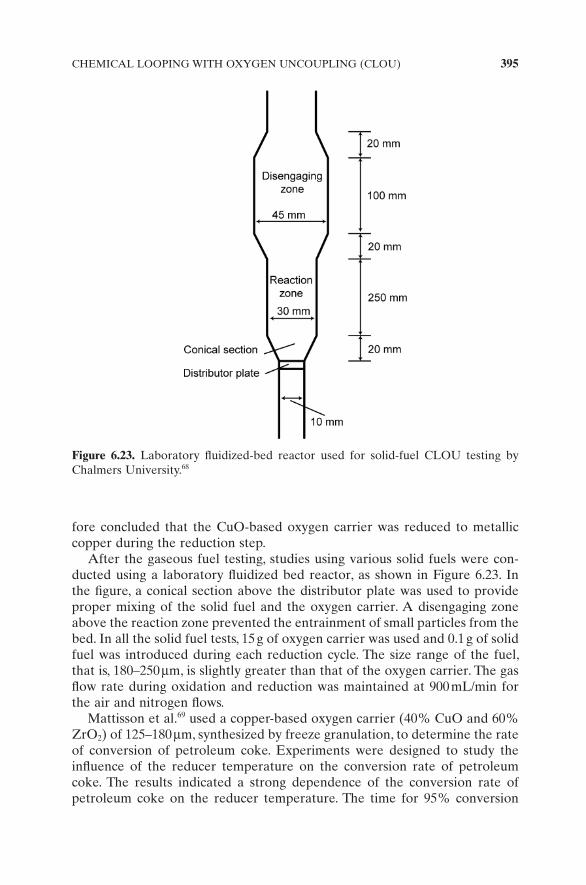
After the gaseous fuel testing, studies using various solid fuels were con-ducted using a laboratory fl uidized bed reactor, as shown in Figure 6.23 . In the fi gure, a conical section above the distributor plate was used to provide proper mixing of the solid fuel and the oxygen carrier. A disengaging zone above the reaction zone prevented the entrainment of small particles from the bed. In all the solid fuel tests, 15 g of oxygen carrier was used and 0.1 g of solid fuel was introduced during each reduction cycle. The size range of the fuel, that is, 180 – 250 μ m, is slightly greater than that of the oxygen carrier. The gas fl ow rate during oxidation and reduction was maintained at 900 mL/min for the air and nitrogen fl ows.
Mattisson et al. 69 used a copper - based oxygen carrier (40% CuO and 60% ZrO 2 ) of 125 – 180 μ m, synthesized by freeze granulation, to determine the rate of conversion of petroleum coke. Experiments were designed to study the infl uence of the reducer temperature on the conversion rate of petroleum coke. The results indicated a strong dependence of the conversion rate of petroleum coke on the reducer temperature. The time for 95% conversion
Figure 6.23. Laboratory fl uidized - bed reactor used for solid - fuel CLOU testing by Chalmers University. 68

396 NOVEL APPLICATIONS OF CHEMICAL LOOPING TECHNOLOGIES
TABLE 6.4. Solid Fuels Testing Results Using the CLOU Concept: Copper-Based Metal Oxide vs. Iron-Based Metal Oxide71
Type of Fuel
Mexican Petroleum
CokeSouth African
CoalIndonesian
Coal
CLOU CLC CLOU CLC CLOU CLC
Time for 95% Conversion (s) 41 648 40 612 30 282Rate of 95% Conversion (%/s) 2.3 0.15 2.4 0.16 3.2 0.34
Type of Fuel
Columbian CoalGerman Lignite
Swedish Wood Char
CLOU CLC CLOU CLC CLOU CLC
Time for 95% Conversion (s) 51 606 25 84 28 378Rate of 95% Conversion (%/s) 1.9 0.16 3.8 1.13 3.4 0.25
decreased from 130 s to 20 s with an increase in temperature from 885 ° C to 985 ° C. 69 A similar conversion of petroleum coke was observed after 15 minutes when iron - based oxygen carriers were used in a typical CLC scheme, high-lighting the signifi cant conversion rate observed while using the CLOU scheme. 70 Leion et al. 71 tested the conversion rates for six different solid fuels using the copper - based oxygen carrier. The results were compared with those when the CLC scheme is used, and the outcome is summarized in Table 6.4 . All the experiments were carried out at 950 ° C. The oxidation of the oxygen carriers was carried out using 10% O 2 balanced with nitrogen. The table high-lights the increased reaction rates observed when adapting the CLOU scheme for solid fuels. Leion et al. 71 also stated that the methane and CO emissions from the CLOU process are lower than those observed in the typical CLC process.
The activity involving CLOU testing using metal oxides other than copper oxide is limited. The application of the copper - based oxygen carrier is, however, constrained because of the low melting point of copper, as discussed in Chapter 2 . Furthermore, as the extent of decomposition of copper oxide is low, a very high circulation rate of copper oxide is thus required for process applications. So far, the only testing performed has been in a laboratory - scale fl uidized - bed reactor.
6.9 Concluding Remarks
This chapter presents examples of novel applications of chemical looping processes for H 2 storage and onboard H 2 production, CO 2 capture in combus-tion fl ue gas, power generation using fuel cells, SMR, tar sand digestion, and
REFERENCES 397
liquid fuel production. Each application employs a unique feature of the chemical looping strategy that characterizes process intensifi cation, leading to a highly effi cient process system. In these particular applications, metal oxide can be used to assist in tar sand digestion and steam methane reforming. The reduced metal oxide from the reducer can be used for the following applica-tions: onboard H 2 production by reacting it with steam, power production by combusting reduced metal oxide in the fuel cell anode, and generation of steam or heat by reacting it with air. In processes such as CLOU, the metal oxide, instead of being reduced by the fuel, can be decomposed to yield molecular gaseous oxygen in the reducer at a high temperature. It is followed, in the reducer, by combustion of molecular gaseous oxygen with fuel to form CO 2 and steam. When this reaction scheme is implemented, the CLOU process is more effective in combusting the gaseous or solid fuels in the reducer than does the typical chemical looping process. The use of the calcium sorbent for CO 2 capture through the carbonation – calcination – hydration looping reactions provides a high - temperature, sorbent - based CO 2 separation method that is a viable alternative to the traditionally low - temperature, solvent - based separation methods. All these chemical looping examples represent energy conversion systems on the cutting edge of effi ciency and technology where CO 2 separation, pollutant control, and product generation can be achieved readily. Employing the fundamental chemical looping concept, other chemical looping schemes also can be conceived, leading to highly effi cient process applications.
References
1. Carpetis , C. , “ Estimation of Storage Costs for Large Hydrogen Storage Facilities , ” International Journal of Hydrogen Energy , 7 ( 2 ), 191 – 203 ( 1982 ).
2. DeLuchi , M. A. , “ Hydrogen vehicles: An Evaluation of Fuel Storage, Performance, Safety, Environmental Impacts and Cost , ” International Journal of Hydrogen Energy , 14 ( 2 ), 81 – 130 ( 1989 ).
3. Kukkone , C. A. , and M. Shelef , “ Hydrogen as an Alternative Automotive Fuel , ” Alternate Fuel , R. M. Bata, National Research Council and National Academy of Engineering. Washington, DC, National Academies Press ( 1992 ).
4. Chambers , A. , C. Park , R. T. K. Baker , and N. M. Rodriguez , “ Hydrogen Storage in Graphite Nanofi bers , ” Journal of Physical Chemistry B , 102 ( 22 ), 4253 – 4256 ( 1998 ).
5. Michel , F. , H. Fieseler , G. Meyer , and F. Thei ß en , “ On - Board Equipment for Liquid Hydrogen Vehicles , ” International Journal of Hydrogen Energy , 23 ( 3 ), 191 – 199 ( 1998 ).
6. Newson , E. , TH. Haletter , P. Hottinger , F. Von Roth , G. W. H. Scherer , and TH. H. Schucan , “ Seasonal Storage of Hydrogen in Stationary Systems with Liquid Organic Hydrides , ” International Journal of Hydrogen Energy , 23 ( 10 ), 905 – 909 ( 1998 ).
7. Verbetsky , V. N. , S. P. Malyshenko , S. V. Mitrokhin , V. V. Solovei , and Y. F. Shmal’ko , “ Metal Hydrides: Properties and Practical Applications – Review of the Works in CIS - Countries , ” International Journal of Hydrogen Energy , 23 ( 12 ), 1165 – 1177 ( 1998 ).
398 NOVEL APPLICATIONS OF CHEMICAL LOOPING TECHNOLOGIES
8. Crabtree , G. W. , M. S. Dresselhaus , and M. V. Buchanan , “ The Hydrogen Economy , ” Physics Today , 5 ( 12 ), 39 – 44 ( 2004 ).
9. U.S. Department of Energy , “ The 2007 Annual Progress Report , ” Hydrogen Program, http://www.hydrogen.energy.gov/annual_progress07.html ( 2008 ).
10. Satyapal , S. , J. Petrovic , C. Read , G. Thomas , and G. Ordaz , “ The U. S. Department Energy ’ s National Hydrogen Storage Project: Progress towards Meeting Hydrogen - Powered Vehicle Requirements , ” Catalysis Today , 120 ( 3 – 4 ), 246 – 256 ( 2007 ).
11. Pant , K. K. , and R. B. Gupta , “ Fundamental and Use of Hydrogen as a Fuel , ” in Hydrogen Fuel: Production, Transport, and Storage , edited by R. B. Gupta , CRC Press , Boca Raton, FL ( 2008 ).
12. Satyapal , S. , and G. Thomas , “ Targets for Onboard Hydrogen Storage Systems: An Aid for the Development of Viable Onboard Hydrogen Storage Technologies , ” in Hydrogen Fuel: Production, Transport, and Storage , edited by R. B. Gupta , CRC Press , Boca Raton, FL ( 2008 ).
13. Gao . M. , and R. Krishnamurthy , “ Hydrogen Transmission in Pipelines and Storage in Pressurized and Cryogenic Tanks , ” in Hydrogen Fuel: Production, Transport, and Storage , edited by R. B. Gupta ., CRC Press , Boca Raton, FL ( 2008 ).
14. Burke , A. F. , and M. Gardiner , “ Hydrogen Storage Options: Technologies and Comparisons for Light - Duty Vehicle Applications , ” UCD - ITS - RR - 05 - 01, Institute of Transport Studies, University of California, Davis ( 2005 ).
15. Arnold , G. , and J. Wolf , “ Liquid Hydrogen for Automotive Application Next Generation Fuel for FC and ICE Vehicles , ” Journal of the Cryogenic Society of Japan , 40 ( 6 ), 221 – 230 ( 2005 ).
16. Aceves , S. M. , J. Martines - Frias , and O. Garcia - Villazana , “ Analytical and Experimental Evaluation of Insulated Pressure Vessels for Cryogenic Hydrogen Storage , ” International Journal of Hydrogen Energy , 25 ( 11 ), 1075 – 1085 ( 2000 ).
17. Aceves , S. M. , G. D. Berry , J. Martinez - Frias , and F. Espinosa - Loza , “ Vehicular Storage of Hydrogen in Insulated Pressure Vessels , ” International Journal of Hydrogen Energy , 31 ( 15 ), 2274 – 2283 ( 2006 ).
18. Akiba , E. , “ Research and Development of Hydrogen Storage Technologies , ” Journal of the Japan Institute of Energy , 85 ( 7 ), 510 – 516 ( 2006 ).
19. Heung , L. K. , and G. G. Wicks , “ Silica Embedded Metal Hydrides , ” Journal of Alloys and Compounds , 293 – 295 , 446 – 451 ( 1999 ).
20. Bogdanovic , B. , and M. Schwickardi , “ Ti - doped NaAlH 4 as a Hydrogen - Storage Material – Preparation by Ti - Catalyzed Hydrogenation of Aluminum Powder in Conjunction with Sodium Hydride , ” Applied Physics A , ( 72 ), 221 – 223 ( 2001 ).
21. Heung , L. K. , “ Using Metal Hydride to Store Hydrogen , ” U.S. Department of Commerce, National Technical Information Service, Springfi eld, VA ( 2003 ).
22. Browman , R. C. , Jr ., S. - J. Hwang , C. C. Ahn , and J. J. Vajo , NMR and X - ray Diffraction Studies of Phases in the Destabilized LiH - Si System , Materials Research Society Symposium Proceedings, 837, N3.6.1 – N3.6.6 ( 2005 ).
23. Li , S. , and P. Jena , Electronic Structure and Hydrogen Desorption in NaAlH 4 , Materials Research Society Symposium Proceedings, 837, N2.5.1 – N2.5.8 ( 2005 ).
24. Bruster , E. , T. A. Dobbins , R. Tittsworth , and D. Anton , Decomposition Behavior of Ti - Doped NaAlH 4 Using X - Ray Absorption Spectroscopy at the Titanium K - Edge , Materials Research Society Symposium Proceedings, 837, N3.4.1 – N.3.4.6 ( 2005 ).
REFERENCES 399
25. Araujo , C. M. , R. Ahuja , and J. M. O. Guillen , “ Role of Titanium in Hydrogen Desorption in Crystalline Sodium Alanate , ” Applied Physics Letters , 86 ( 25 ), 251913 1 – 3 ( 2005 ).
26. Schuth , F. , B. Bogdanovic , and M. Felderhof , “ Light Metal Hydrides and Complex Hydrides for Hydrogen Storage , ” Chemical Communications , 24 , 2249 – 2258 ( 2004 ).
27. Garberoglio , G. , A. I. Skoulidas , and J. K. Johnson , “ Adsorption of Gases in Metal Organic Materials: Comparison of Simulations and Experiments , ” Journal of Physical Chemistry B , 109 ( 27 ), 13094 – 13103 ( 2005 ).
28. Rosi , N. L. , J. Eckert , M. Eddaoudi , D. T. Vodak , J. Kim , M. O’ Keeffe , and O. M. Yaghi ., “ Hydrogen Storage in Microporous Metal - Organic Frameworks , ” Science , 300 , 1127 ( 2003 ).
29. Jung , D. H. , D. Kim , T. B. Lee , T Lee , S. B. Choi , J. H. Yoon , J. Kim , K. Choi , and S. - H. Choi , “ Grand Canonical Monte Carlo Simulation Study on the Catenation Effect on Hydrogen Adsorption onto the Interpenetrating Metal − Organic Frameworks , ” Journal of Physical Chemistry B , 110 ( 46 ), 22987 – 22990 ( 2006 ).
30. Li , Y. , F. H. Yang , and R. T. Yang , “ Kinetics and Mechanistic Model for Hydrogen Spillover on Bridged Metal − Organic Frameworks , ” Journal of Physical Chemistry C , 111 ( 8 ), 3405 – 3411 ( 2007 ).
31. Li , Y. , and R. T. Yang , “ Hydrogen Storage in Metal − Organic Frameworks by Bridged Hydrogen Spillover , ” Journal of the American Chemical Society , 128 ( 25 ), 8136 – 8137 ( 2006 ).
32. Dillon , A. C. , J. L. Blackburn , P. A. Parilla , Y. , Zhao , Y. - H. Kim , S. B. Zhang , A. H. Mahan , J. L. Alleman , K. M. Jones , K. E. H. Gillbert , et al. Discovering the Mechanism of H 2 Adsoprtion on Aromatic Carbon Nanostructures to Develop Adsorbents for Vehicular Applications , Materials Research Society Symposium Proceedings, 837, N4.2.1 – N4.2.7 ( 2005 ).
33. Lee , Y. W. , R. Deshpande , A. C. Dillon , M. J. Heben , H. Dai , and B. M. Clemens , The Role of Metal Catalyst in Near Ambient Hydrogen Adsorption on Multi - walled Carbon Nanotubes , Materials Research Society Symposium Proceedings, 837, N3.18.1 – N3.18.6 ( 2005 ).
34. Wang , Y. , and Z. Iqbal , Electrochemical Hydrogen Adsorption/Storage in Pure and Functionalized Single Wall Carbon Nanotubes , Materials Research Society Symposium Proceedings , 837 , N4.4.1 – N4.4.12 ( 2005 ).
35. Gupta , B. K. , R. S. Tiwari , and O. N. Srivastava , “ Studies on Synthesis and Hydrogenation Behavior of Graphite Nanofi bers Prepared through Palladium Catalyst Assisted Thermal Cracking of Acetylene , ” Journal of Alloys and Compounds , 381 , 301 – 308 ( 2004 ).
36. Ahn , C. C. , Y. Ye , B. V. Ratnakumar , C. Witham , R. C. Bowman , and B. Fultz , “ Hydrogen Desorption and Adsorption Measurements on Graphite Nanofi bers , ” Applied Physics Letters , 73 , 3378 – 3380 ( 1998 ).
37. Fan , Y. - Y. , B. Liao , M. Liu , Y. - L. Wei , M. - Q. Lu , and H. - M. Cheng , “ Hydrogen Uptake in Vapor - Grown Carbon Nanofi bers , ” Carbon , 37 , 1649 – 1652 ( 1999 ).
38. Hong , S. E. , D. – K. Kim , S. M. Jo , D. Y. Kim , B. D. Chin , and D. W. Lee , “ Graphite Nanofi bers Prepared from Catalytic Graphitization of Electrospun Poly(Vinylidene Fluoride) Nanofi bers and Their Hydrogen Storage Capacity , ” Catalysis Today , 120 , 413 – 419 ( 2007 ).
400 NOVEL APPLICATIONS OF CHEMICAL LOOPING TECHNOLOGIES
39. White C. M. , B. R. Strazisar , E. J. Granite , J. S. Hoffman , and H. W. Pennline , “ Separation and Capture of CO 2 from Large Stationary Sources and Sequestration in Geological Formations – Coalbeds and Deep Saline Aquifers , ” Journal of the Air & Waste Management Association , 53 ( 6 ), 645 – 715 ( 2003 ).
40. Lee , K. B. , A. Verdooren , H. S. Caram , and S. Sircar , “ Chemisorption of Carbon Dioxide on Potassium - Carbonate - Promoted Hydrotalcite , ” Journal of Colloid and Interface Science , 308 , 30 – 39 ( 2007 ).
41. Fan , L. - S. , and R. A. Jadhav , “ Clean Coal Technologies: OSCAR and CARBONOX Commercial Demonstrations , ” AIChE Journal , 48 ( 10 ), 2115 – 2123 ( 2002 ).
42. Fan , L. - S. , H. Gupta , and M. Iyer , “ Separation of Carbon Dioxide (CO 2 ) from Gas Mixtures by Calcium Based Reaction Separation (Cars - CO 2 ) Process, ” U.S. Patent Application Publication Number 2008/0,233,029 .
43. Gupta , H. , S. A. Benson , L. - S. Fan , J. D. Laumb , E. S. Olson , C. R. Crocker , R. K. Sharma , R. Z. Knutson , A. S. M. Rokanuzzaman , and J. E. Tibbets , “ Pilot - Scale Studies of NO x Reduction by Activated High - Sodium Lignite Chars: A Demonstration of the CARBONOX Process , ” Industrial & Engineering Chemistry Research , 43 ( 18 ), 5820 – 5827 ( 2004 ).
44. Taerakul , P. , P. Sun , D. W. Golightly , H. W. Walker , L. K. Weavers , B. Zand , T. Butalia , T. Thomas , H. Gupta , and L. - S. Fan , “ Characterization and Re - Use Potential of By - Products Generated from the Ohio State Carbonation and Ash Reactivation (OSCAR) Process , ” Fuel , 86 ( 4 ), 541 – 553 ( 2007 ).
45. Fan , L. - S. , and H. Gupta , “ Sorbent for the Separation of Carbon Dioxide (CO 2 ) from Gas Mixtures, ” U.S. Patent 7,067,456 ( 2006 ).
46. Grasa , G. S. , and J. C. Abanades , “ CO 2 Capture Capacity of CaO in Long Series of Carbonation /Calcination Cycles , ” Industrial & Engineering Chemistry Research , 45 , 8846 – 8851 ( 2006 ).
47. Chrissafi s , K. , “ Multicyclic Study on the Carbonation of CaO Using Different Limestones , ” Journal of Thermal Analysis and Calorimetry , 89 , 525 – 529 ( 2007 ).
48. Fennell , P. S. , R. Paciani , J. S. Dennis , J. F. Davidson , and A. N. Hayhurst , “ The Effects of Repeated Cycles of Calcination and Carbonation on a Variety of Different Limestones, as Measured in a Hot Fluidized Bed of Sand , ” Energy & Fuels , 21 ( 4 ), 2072 – 2081 ( 2007 ).
49. Sun , P. , C. J. Lim , and J. R. Grace , “ Cyclic CO 2 Capture by Limestone - Derived Sorbent During Prolonged Calcination/Carbonation Cycling , ” AIChE Journal , 54 , 1668 – 1677 ( 2008 ).
50. Fan L. - S. , S. Ramkumar , W. Wang , and R. Statnick , “ Separation of Carbon Dioxide from Gas Mixtures by Calcium Based Reaction Separation Process, ” Provisional Patent Application No. 61/116,172 ( 2008 ).
51. Lu , D. Y. , R. W. Hughes , and E. J. Anthony , “ In - Situ CO 2 Capture Using Ca - Based Sorbent Looping in Dual Fluidized Beds , ” Paper presented at the 9th International Conference on Circulating Fluidized Beds, Hamburg, Germany ( 2008 ).
52. Manovic V. , and E. J. Anthony , “ Parametric Study on the CO 2 Capture Capacity of CaO - Based Sorbents in Looping Cycles , ” Energy and Fuels , 22 ( 3 ), 1851 – 1857 ( 2008 ).
53. Manovic V. , and E. J. Anthony , “ Thermal Activation of CaO - Based Sorbent and Self - Reactivation During CO 2 Capture Looping Cycles , ” Environmental Science & Technology , 42 ( 11 ), 4170 – 4174 ( 2008 ).
REFERENCES 401
54. Manovic V. , and E. J. Anthony , “ Sequential SO 2 /CO 2 Capture Enhanced by Steam Reactivation of a CaO - Based Sorbent , ” Fuel , 87 ( 8/9 ), 1564 – 1573 ( 2008 ).
55. Jin , H. , and M. Ishida , “ A New Type of Coal Gas Fueled Chemical - Looping Combustion , ” Fuel , 83 , 2411 – 2417 ( 2004 ).
56. Gupta , P. , L. G. Velazquez - Vargas , T. Thomas , and L. - S. Fan , Process of Chemical Looping Combustion of Coal , 30 th Proceedings of the 30th International Technical Conference on Coal Utilization & Fuel Systems, Clearwater, Florida, April 17 – 21 , ( 2005 ).
57. Garcia - Labiano , F. , J. Adanez , L. F. de Diego , P. Gayan , and A. Abad , “ Effect of Pressure on the Behavior of Copper - , Iron - , and Nickel - Based Oxygen Carriers for Chemical - Looping Combustion , ” Energy & Fuels , 20 ( 1 ), 26 – 33 ( 2006 ).
58. Kronberger , B. , A. Lyngfelt , G. Loeffl er , and H. Hofbauer , “ Design and Fluid Dynamic Analysis of a Bench - Scale Combustion System with CO 2 Separation − Chemical - Looping Combustion , ” Industrial & Engineering Chemistry Research , 44 ( 3 ), 546 – 556 ( 2005 ).
59. Fan , L. - S. , F. L i, L. Zeng , and D. Sridhar , “ Integration of Reforming/Water Splitting and Electrochemical Systems for Power Generation with Integrated Carbon Capture ” , Provisional Patent Application Number 61/240,508 ( 2009 ).
60. Chuang , S. S. C. , “ Catalysis of Solid Oxide Fuel Cell , ” Catalysis , 18 , 186 – 198 ( 2005 ). 61. Chuang , S. S. C. , “ Coal - Based Fuel Cell, ” WO 2,006,028,502 ( 2006 ). 62. Ryden , M. , and A. Lyngfelt , “ Using Steam Reforming to Produce Hydrogen with
Carbon Dioxide Capture by Chemical - Looping Combustion , ” International Journal of Hydrogen energy , 31 ( 10 ), 1271 – 1283 ( 2006 ).
63. Riedel T. , M. Claeys , H. Schulz . , G. Schaub , S. S. Nam , K. W. Jun , M. J. Choi , G. Kishan , and K. W. Lee , “ Comparative Study of Fischer - Tropsch Synthesis with H 2 /CO and H 2 /CO 2 Syngas Using Fe - and Co - Based Catalysts , ” Applied Catalysis A - General , 186 ( 1 – 2 ), 201 – 213 ( 1999 ).
64. Riedel , T. , G. Schaub , K. W. Jun , and K. W. Lee , “ Kinetics of CO 2 Hydrogenation on a K - Promoted Fe Catalyst , ” Industrial & Engineering Chemistry Research , 40 ( 5 ), 1355 – 1363 ( 2001 ).
65. Hildebrandt , D. , D. Glasser , B. Hausberger , B. Patel , and B. Glasser , “ Producing Transportation Fuels with Less Work , ” Science , 323 , 1680 – 1681 ( 2009 ).
66. Fan , L. - S. , F. L i, and L. Zeng , “ Synthetic Fuels and Chemicals Production with In - Situ CO 2 Capture, ” Provisional Patent Application Number 61/240446 ( 2009 ).
67. Lewis , W. K. , and E. R. Gilliland , “ Production of Pure Carbon Dioxide, ” U.S. Patent 2,665,972 ( 1954 ).
68. Mattisson , T. , A. Lyngfelt , and H. Leion , “ Chemical - Looping with Oxygen Uncoupling for Combustion of Solid Fuels , ” International Journal of Greenhouse Gas Control , 3 ( 1 ), 11 – 19 ( 2009 ).
69. Mattisson , T. , H. Leion , and A. Lyngfelt , “ Chemical - Looping with Oxygen Uncoupling Using CuO/ZrO 2 with Petroleum Coke , ” Fuel , 88 ( 4 ), 683 – 690 ( 2009 ).
70. Leion , H. , T. Mattisson , and A. Lyngfelt , “ The Use of Petroleum Coke as Fuel in Chemical – Looping Combustion , ” Fuel , 86 ( 12 – 13 ), 1947 – 1958 ( 2007 ).
71. Leion , H. , T. Mattisson , and A. Lyngfelt , “ Using Chemical - Looping with Oxygen Uncoupling (CLOU) for Combustion of Six Different Solid Fuels , ” Energy Procedia , 1 , 447 – 453 ( 2009 ).