chemical looping technology - columbia...
TRANSCRIPT
Chemical Looping Technology
L. S. Fan
Department of Chemical and Biomolecular Engineering
The Ohio State University Columbus, Ohio 43210
by
Columbia University April 16, 2014
2
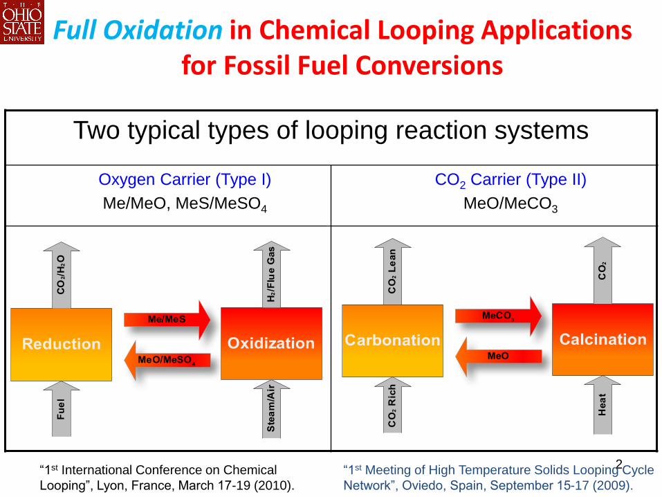
Full Oxidation in Chemical Looping Applications for Fossil Fuel Conversions
Two typical types of looping reaction systems
Oxygen Carrier (Type I)
Me/MeO, MeS/MeSO4
CO2 Carrier (Type II)
MeO/MeCO3
“1st Meeting of High Temperature Solids Looping Cycle
Network”, Oviedo, Spain, September 15-17 (2009).
“1st International Conference on Chemical
Looping”, Lyon, France, March 17-19 (2010).
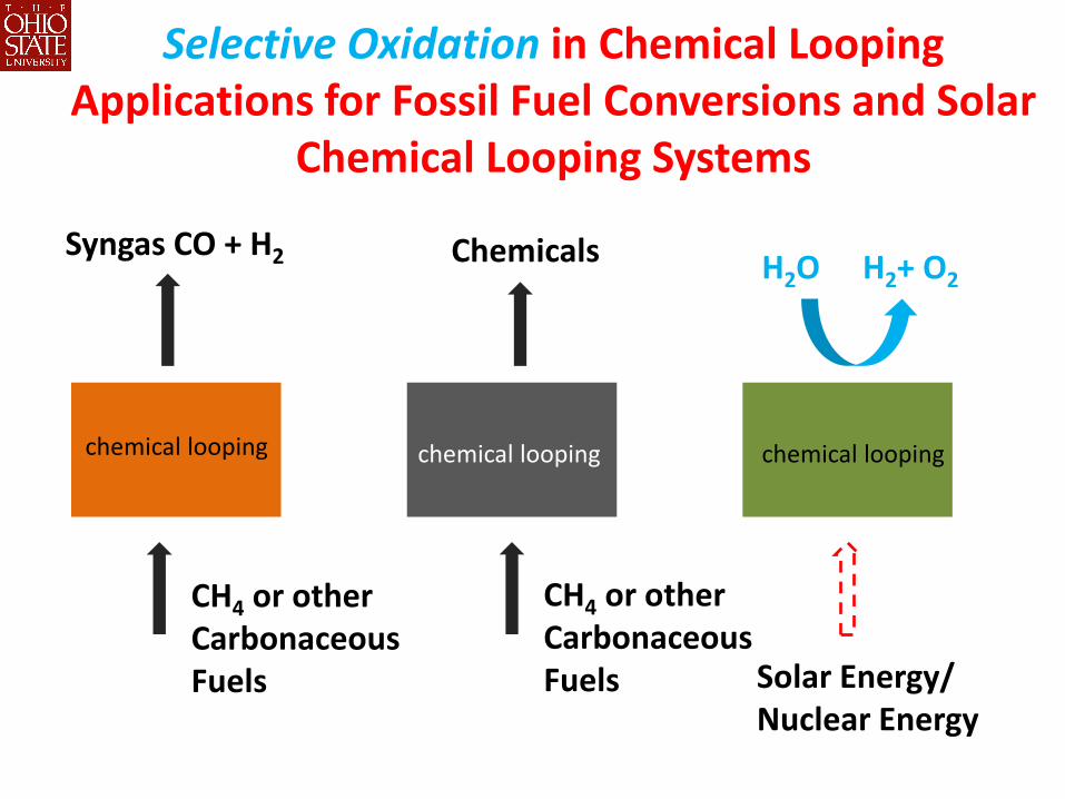
Selective Oxidation in Chemical Looping Applications for Fossil Fuel Conversions and Solar
Chemical Looping Systems
CH4 or other Carbonaceous Fuels
CH4 or other Carbonaceous Fuels
Syngas CO + H2
Chemicals
Solar Energy/ Nuclear Energy
H2O H2+ O2
chemical looping chemical looping chemical looping
0
10
20
30
40
50
60
70
80
90
0 20 40 60 80 100
% Electricity
Ov
era
ll P
roc
es
s E
ffic
ien
cy
0
10
20
30
40
50
60
70
80
90
SCL
Gasfication-WGS
IGCC-SELEXOL
Subcritical MEA
Ultra-supercritical MEA
Ultra-Supercritical Chilled Ammonia
Syngas CLC
H2 Membrane WGS
CO2 Membrane WGS
CDCL
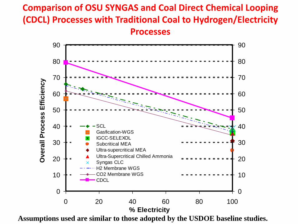
Comparison of OSU SYNGAS and Coal Direct Chemical Looping (CDCL) Processes with Traditional Coal to Hydrogen/Electricity
Processes
Assumptions used are similar to those adopted by the USDOE baseline studies.
5
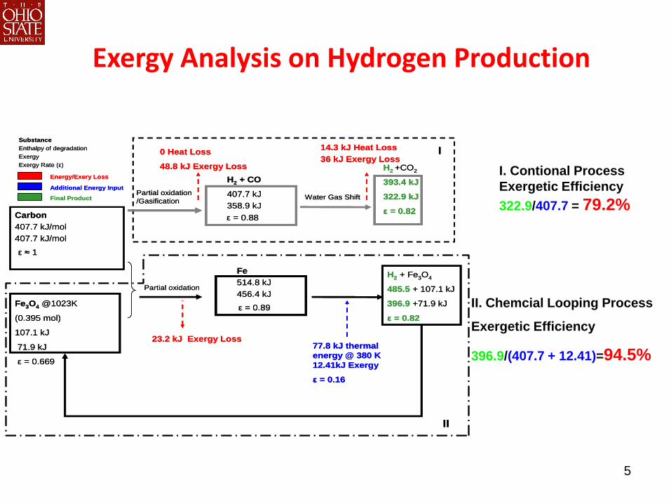
ε ≈ 1
Partial oxidation
/Gasification
ε = 0.88
H2 + CO
407.7 kJ
358.9 kJ
0 Heat Loss
48.8 kJ Exergy Loss
Water Gas Shift
H2 +CO2
393.4 kJ
322.9 kJ
ε = 0.82
ε = 0.89
Fe
514.8 kJ
456.4 kJFe3O4 @1023K
(0.395 mol)
107.1 kJ
71.9 kJ
ε = 0.669
14.3 kJ Heat Loss
36 kJ Exergy Loss
H2 + Fe3O4
485.5 + 107.1 kJ
396.9 +71.9 kJ
ε = 0.82
Carbon
407.7 kJ/mol
407.7 kJ/mol
23.2 kJ Exergy Loss77.8 kJ thermal
energy @ 380 K
12.41kJ Exergy
ε = 0.16
Partial oxidation
I
II
Substance
Enthalpy of degradation
Exergy
Exergy Rate (ε)
Energy/Exery Loss
Additional Energy Input
Final Product
I. Contional Process
Exergetic Efficiency
322.9/407.7 = 79.2%
II. Chemcial Looping Process
Exergetic Efficiency
396.9/(407.7 + 12.41)=94.5%
Exergy Analysis on Hydrogen Production
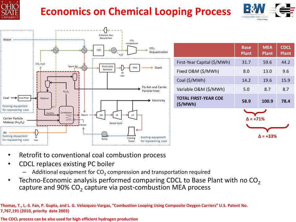
Economics on Chemical Looping Process
Thomas, T., L.-S. Fan, P. Gupta, and L. G. Velazquez-Vargas, “Combustion Looping Using Composite Oxygen Carriers” U.S. Patent No. 7,767,191 (2010, priority date 2003)
The CDCL process can be also used for high efficient hydrogen production
Reducer
Combustor
Pump
Coal Prep.Coal
CO2
compressor
Particulate Removal
FGD Stack
CO2
Sequestration
LPIPHP
Air
Fe2O3
Cooling Tower
ID Fan
Water
ID Fan
H2O
CO2+H2O
Enhancer Gas Recycle Fan
Electricity
Carrier Particle Makeup (Fe2O3)
Fly Ash and Carrier Particle Fines
FGD
Spent Air
Steam
WaterSteam Cycle
FeO/Fe
Existing equipment for repowering case
Existing equipment for repowering case
Existing equipment for repowering case
Base Plant
MEA Plant
CDCL Plant
First-Year Capital ($/MWh) 31.7 59.6 44.2
Fixed O&M ($/MWh) 8.0 13.0 9.6
Coal ($/MWh) 14.2 19.6 15.9
Variable O&M ($/MWh) 5.0 8.7 8.7
TOTAL FIRST-YEAR COE ($/MWh)
58.9 100.9 78.4
∆ = +71%
∆ = +33%
• Retrofit to conventional coal combustion process • CDCL replaces existing PC boiler
– Additional equipment for CO2 compression and transportation required
• Techno-Economic analysis performed comparing CDCL to Base Plant with no CO2 capture and 90% CO2 capture via post-combustion MEA process
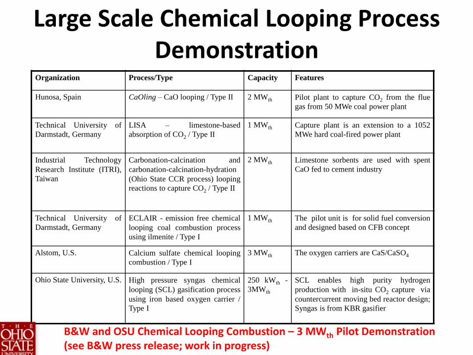
Large Scale Chemical Looping Process Demonstration
Organization Process/Type Capacity Features
Hunosa, Spain CaOling – CaO looping / Type II 2 MWth Pilot plant to capture CO2 from the flue
gas from 50 MWe coal power plant
Technical University of
Darmstadt, Germany LISA – limestone-based
absorption of CO2 / Type II 1 MWth Capture plant is an extension to a 1052
MWe hard coal-fired power plant
Industrial Technology
Research Institute (ITRI),
Taiwan
Carbonation-calcination and
carbonation-calcination-hydration
(Ohio State CCR process) looping
reactions to capture CO2 / Type II
2 MWth Limestone sorbents are used with spent
CaO fed to cement industry
Technical University of
Darmstadt, Germany ECLAIR - emission free chemical
looping coal combustion process
using ilmenite / Type I
1 MWth The pilot unit is for solid fuel conversion
and designed based on CFB concept
Alstom, U.S. Calcium sulfate chemical looping
combustion / Type I 3 MWth The oxygen carriers are CaS/CaSO4
Ohio State University, U.S. High pressure syngas chemical
looping (SCL) gasification process
using iron based oxygen carrier /
Type I
250 kWth -
3MWth SCL enables high purity hydrogen
production with in-situ CO2 capture via
countercurrent moving bed reactor design;
Syngas is from KBR gasifier
B&W and OSU Chemical Looping Combustion – 3 MWth Pilot Demonstration (see B&W press release; work in progress)

Ellingham Diagram: Selection of Primary Metal
Oxygen Carrier Particle Development
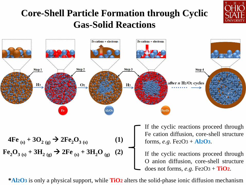
Core-Shell Particle Formation through Cyclic
Gas-Solid Reactions
4Fe (s) + 3O2 (g) 2Fe2O3 (s) (1)
Fe2O3 (s) + 3H2 (g) 2Fe (s) + 3H2O (g) (2)
If the cyclic reactions proceed through
Fe cation diffusion, core-shell structure
forms, e.g. Fe2O3 + Al2O3.
If the cyclic reactions proceed through
O anion diffusion, core-shell structure
does not forms, e.g. Fe2O3 + TiO2.
*Al2O3 is only a physical support, while TiO2 alters the solid-phase ionic diffusion mechanism
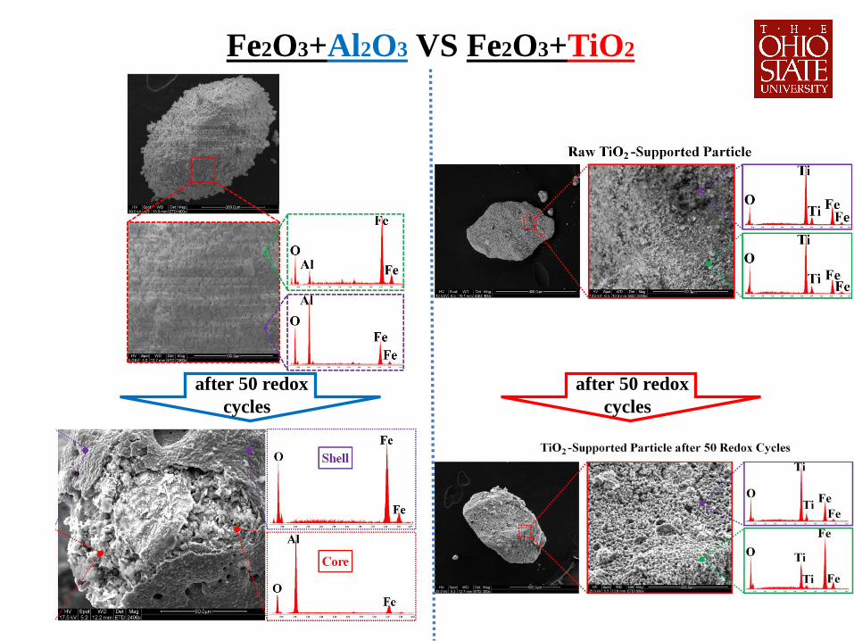
Fe2O3+Al2O3 VS Fe2O3+TiO2
after 50 redox
cycles
after 50 redox
cycles
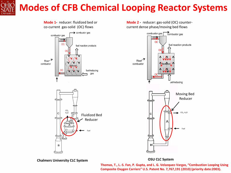
Modes of CFB Chemical Looping Reactor Systems Mode 1- reducer: fluidized bed or
co-current gas-solid (OC) flows Mode 2 - reducer: gas-solid (OC) counter-
current dense phase/moving bed flows
Thomas, T., L.-S. Fan, P. Gupta, and L. G. Velazquez-Vargas, “Combustion Looping Using Composite Oxygen Carriers” U.S. Patent No. 7,767,191 (2010) (priority date:2003).
OSU CLC System Chalmers University CLC System
Fuel
CO2 H2O CO2, H2O
Moving Bed Reducer
Fuel
Fluidized Bed Reducer
12
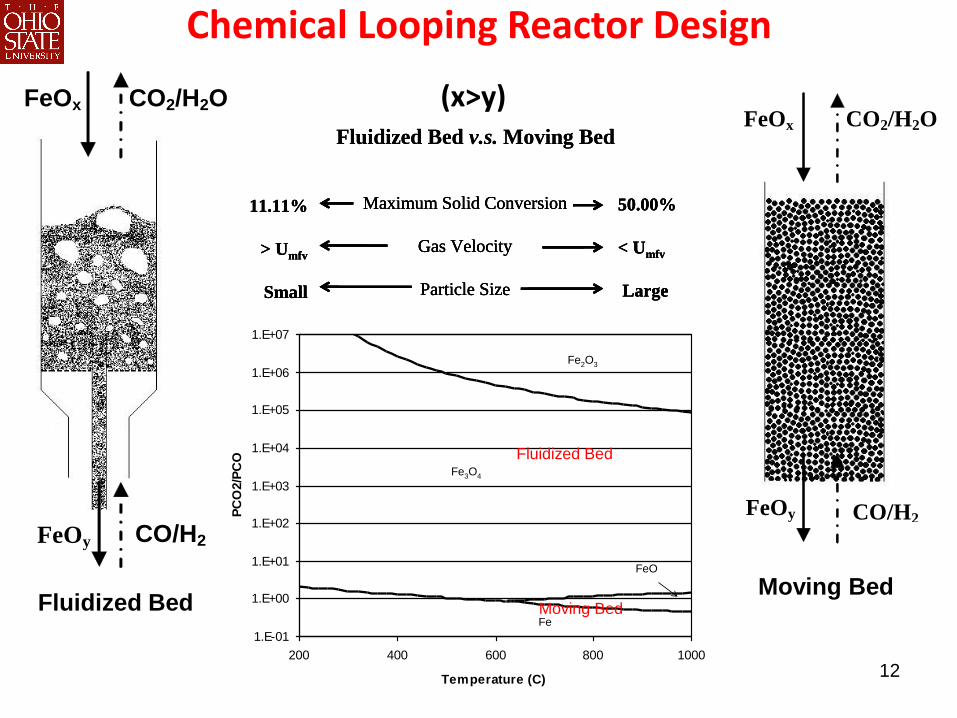
Chemical Looping Reactor Design
FeOy
FeOx
CO/H2
CO2/H2O
(x>y)
FeOy CO/H2
(x>y)
FeOx CO2/H2O
Fluidized Bed Moving Bed
FeOy CO/H2
(X>Y)
FeOx CO2/H2O
Fluidized Bed Moving Bed
Moving Bed – The Selected Reactor Type
FeOy
FeOx
CO/H2
CO2/H2O
(X>Y)
Fluidized Bed v.s. Moving Bed
Maximum Solid Conversion
Gas Velocity
Particle Size
11.11%
> Umfv
Small
50.00%
< Umfv
Large
Fluidized Bed v.s. Moving Bed
Maximum Solid Conversion
Gas Velocity
Particle Size
11.11%
> Umfv
Small
50.00%
< Umfv
Large
Maximum Solid Conversion
Gas Velocity
Particle Size
11.11%
> Umfv
Small
50.00%
< Umfv
Large
1.E-01
1.E+00
1.E+01
1.E+02
1.E+03
1.E+04
1.E+05
1.E+06
1.E+07
200 400 600 800 1000
Temperature (C)
PC
O2/P
CO
Fe2O3
Fe3O4
FeO
Fe
1.E-01
1.E+00
1.E+01
1.E+02
1.E+03
1.E+04
1.E+05
1.E+06
1.E+07
200 400 600 800 1000
Temperature (C)
PC
O2/P
CO
Fe2O3
Fe3O4
FeO
Fe
Fluidized Bed
Moving Bed
(x>y)
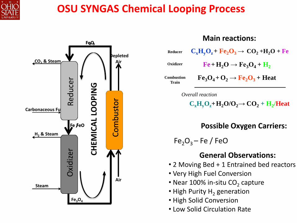
OSU SYNGAS Chemical Looping Process
Possible Oxygen Carriers:
Fe2O3 – Fe / FeO
Main reactions:
General Observations: • 2 Moving Bed + 1 Entrained bed reactors • Very High Fuel Conversion • Near 100% in-situ CO2 capture • High Purity H2 generation • High Solid Conversion • Low Solid Circulation Rate
Fe3O4 + O2 → Fe2O3 + Heat
Overall reaction
CxHyOz+H2O/O2→ CO2 + H2/Heat
CxHyOz+ Fe2O3 → CO2 +H2O + Fe
Fe + H2O → Fe3O4 + H2
Reducer
Oxidizer
Combustion
Train
Red
uce
r O
xid
izer
Co
mb
ust
or
Carbonaceous Fuel
Fe / FeO
Fe 2 O 3
CH
EMIC
AL
LOO
PIN
G
Red
uce
r O
xid
izer
Co
mb
ust
or
CO2 & Steam
H2 & Steam
Steam
Fe / FeO
Fe3O4
Fe 2 O 3
Air
Depleted Air
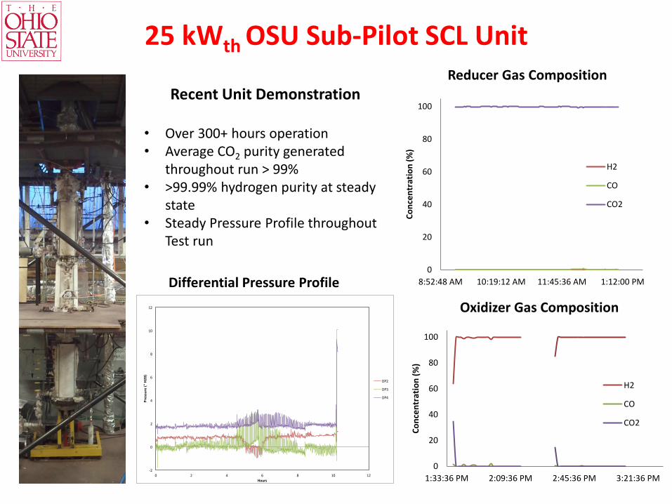
25 kWth OSU Sub-Pilot SCL Unit Reducer Gas Composition
0
20
40
60
80
100
1:33:36 PM 2:09:36 PM 2:45:36 PM 3:21:36 PM
Co
nce
ntr
atio
n (
%)
H2
CO
CO2
Oxidizer Gas Composition
0
20
40
60
80
100
8:52:48 AM 10:19:12 AM 11:45:36 AM 1:12:00 PM
Co
nce
ntr
atio
n (
%)
H2
CO
CO2
Recent Unit Demonstration
• Over 300+ hours operation • Average CO2 purity generated
throughout run > 99% • >99.99% hydrogen purity at steady
state • Steady Pressure Profile throughout
Test run
-2
0
2
4
6
8
10
12
0 2 4 6 8 10 12
Pressure("H20)
Hours
DP2
DP3
DP4
Differential Pressure Profile
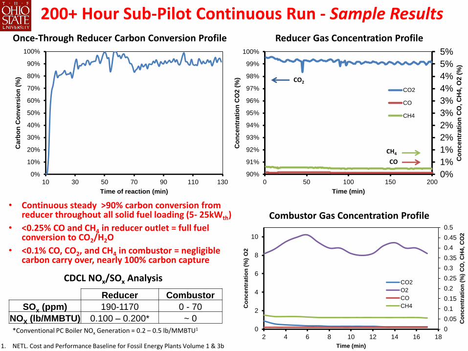
Once-Through Reducer Carbon Conversion Profile Reducer Gas Concentration Profile
200+ Hour Sub-Pilot Continuous Run - Sample Results
0%
1%
1%
2%
2%
3%
3%
4%
4%
5%
5%
90%
91%
92%
93%
94%
95%
96%
97%
98%
99%
100%
0 50 100 150 200
Co
ncen
trati
on
CO
, C
H4,
O2 (
%)
Co
ncen
trati
on
CO
2 (
%)
Time (min)
CO2
CO
CH4
CH4
CO2
CO
0%
10%
20%
30%
40%
50%
60%
70%
80%
90%
100%
10 30 50 70 90 110 130
Carb
on
Co
nv
ers
ion
(%
)
Time of reaction (min)
0
0.05
0.1
0.15
0.2
0.25
0.3
0.35
0.4
0.45
0.5
0
2
4
6
8
10
2 4 6 8 10 12 14 16 18
Co
nc
en
tra
tio
n (
%)
CO
, C
H4
, C
O2
Co
nc
en
tra
tio
n (
%)
O2
Time (min)
CO2
O2
CO
CH4
Combustor Gas Concentration Profile
Reducer Combustor
SOx (ppm) 190-1170 0 - 70
NOX (lb/MMBTU) 0.100 – 0.200* ~ 0
1. NETL. Cost and Performance Baseline for Fossil Energy Plants Volume 1 & 3b
*Conventional PC Boiler NOx Generation = 0.2 – 0.5 lb/MMBTU1
CDCL NOx/SOx Analysis
• Continuous steady >90% carbon conversion from reducer throughout all solid fuel loading (5- 25kWth)
• <0.25% CO and CH4 in reducer outlet = full fuel conversion to CO2/H2O
• <0.1% CO, CO2, and CH4 in combustor = negligible carbon carry over, nearly 100% carbon capture
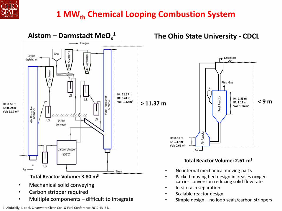
1 MWth Chemical Looping Combustion System
Alstom – Darmstadt MeOx1 The Ohio State University - CDCL
Ht: 1.83 m ID: 1.17 m Vol: 1.96 m3
Ht: 0.61 m ID: 1.17 m Vol: 0.65 m3
Ht: 11.37 m ID: 0.41 m Vol: 1.42 m3
Ht: 8.66 m ID: 0.59 m Vol: 2.37 m3
> 11.37 m < 9 m
Total Reactor Volume: 3.80 m3 • No internal mechanical moving parts • Packed moving bed design increases oxygen
carrier conversion reducing solid flow rate • In-situ ash separation • Scalable reactor design • Simple design – no loop seals/carbon strippers
1. Abdulally, I. et al. Clearwater Clean Coal & Fuel Conference 2012 43–54.
Total Reactor Volume: 2.61 m3
• Mechanical solid conveying • Carbon stripper required • Multiple components – difficult to integrate