chapter2 angle
DESCRIPTION
angleTRANSCRIPT

EKT343 –Principle of Communication Engineering 1

Angle modulation is the process by which the angle (frequency or phase) of the carrier signal is changed in accordance with the instantaneous amplitude of modulating or message signal.
2EKT343 –Principle of Communication
Engineering
classified into two types such as Frequency modulation (FM) Phase modulation (PM)
Used for : Commercial radio broadcasting Television sound transmission Two way mobile radio Cellular radio Microwave and satellite communication system
3EKT343 –Principle of Communication
Engineering

Advantages over AM:Freedom from interference: all natural and external
noise consist of amplitude variations, thus receiver usually cannot distinguish between amplitude of noise or desired signal. AM is noisy than FM.
Operate in very high frequency band (VHF): 88MHz-108MHz
Can transmit musical programs with higher degree of fidelity.
4EKT343 –Principle of Communication
Engineering
In FM, the carrier amplitude remains constant, the carrier frequency varies with the amplitude of modulating signal.
The amount of change in carrier frequency produced by the modulating signal is known as frequency deviation.
5EKT343 –Principle of Communication
Engineering
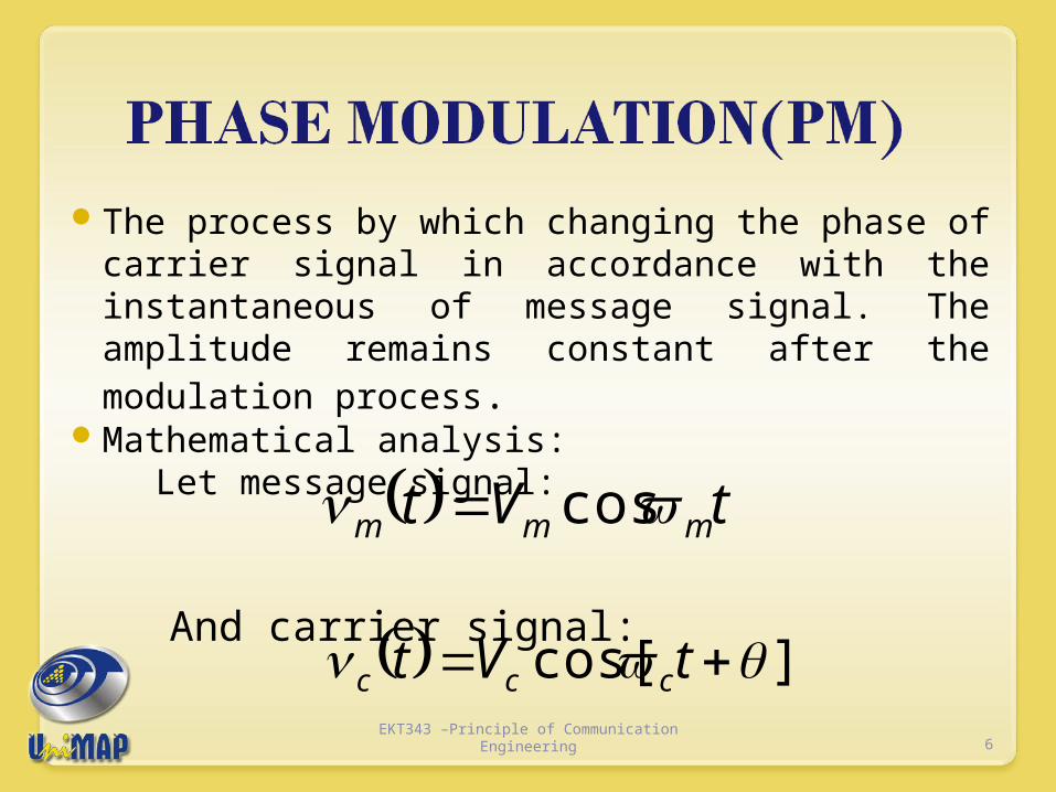
The process by which changing the phase of carrier signal in accordance with the instantaneous of message signal. The amplitude remains constant after the modulation process.
Mathematical analysis: Let message signal:
And carrier signal:
tVt mmm cos
]cos[ tVt ccc
6EKT343 –Principle of Communication
Engineering
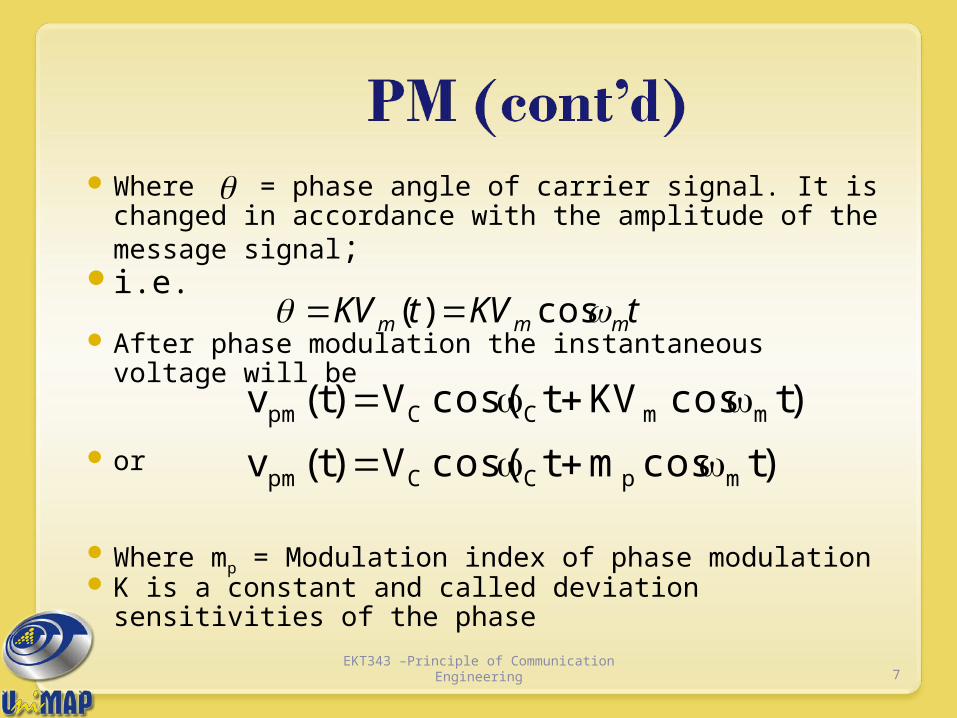
Where = phase angle of carrier signal. It is changed in accordance with the amplitude of the message signal;
i.e.
After phase modulation the instantaneous voltage will be
or
Where mp = Modulation index of phase modulation K is a constant and called deviation sensitivities of
the phase
tKVtKV mmm cos)(
)tcosmtcos(V)t(v
)tcosKVtcos(V)t(v
mpCCpm
mmCCpm
7EKT343 –Principle of Communication
Engineering
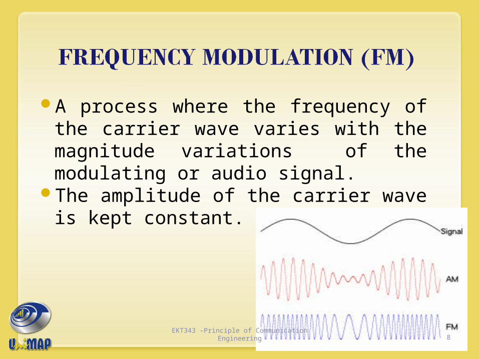
A process where the frequency of the carrier wave varies with the magnitude variations of the modulating or audio signal.
The amplitude of the carrier wave is kept constant.
8EKT343 –Principle of Communication
Engineering

9EKT343 –Principle of Communication
Engineering

EKT343 –Principle of Communication Engineering 10
Carrier
ModulatingSignal
FMsignal
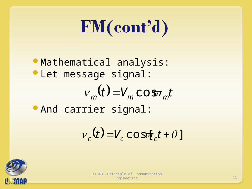
Mathematical analysis:Let message signal:
And carrier signal:
tVt mmm cos
]cos[ tVt ccc
11EKT343 –Principle of Communication
Engineering
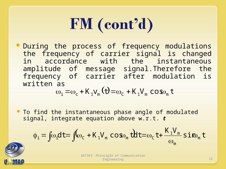
During the process of frequency modulations the frequency of carrier signal is changed in accordance with the instantaneous amplitude of message signal.Therefore the frequency of carrier after modulation is written as
To find the instantaneous phase angle of modulated signal, integrate equation above w.r.t. t
tcosVKtvK mm1Cm1ci
tsinVK
tdttcosVKdt mm
m1Cmm1Cii
12EKT343 –Principle of Communication
Engineering

Thus, we get the FM wave as:
Where modulation index for FM is given by
)tsinVK
tcos(VcosVc)t(v mm
m1CC1FM
)sincos()( tmtVtv mfCCFM
m
m1f
VKm
13EKT343 –Principle of Communication
Engineering
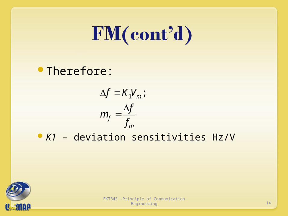
Therefore:
K1 – deviation sensitivities Hz/Vm
f
m
f
fm
VKf
;1
14EKT343 –Principle of Communication
Engineering

TomasiElectronic Communications Systems, 5e
Copyright ©2004 by Pearson Education, Inc.Upper Saddle River, New Jersey 07458
All rights reserved.
15EKT343 –Principle of Communication
Engineering
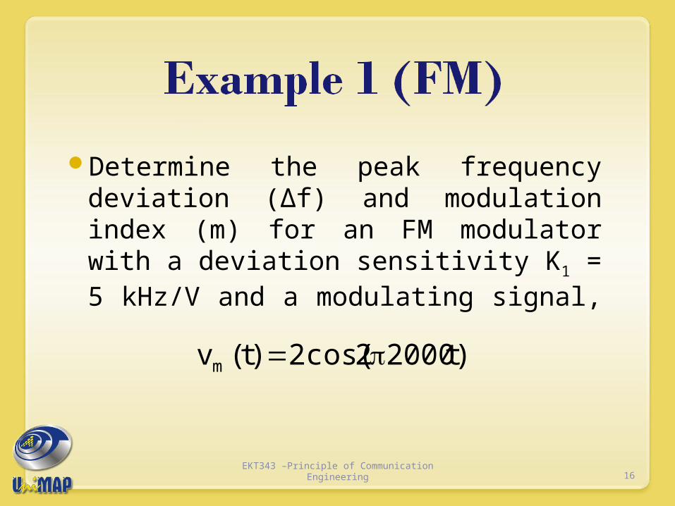
Determine the peak frequency deviation (∆f) and modulation index (m) for an FM modulator with a deviation sensitivity K1 = 5 kHz/V and a modulating signal,
)t20002cos(2)t(vm
16EKT343 –Principle of Communication
Engineering
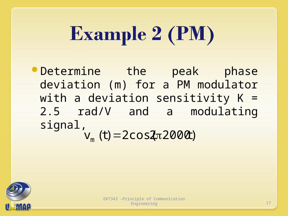
Determine the peak phase deviation (m) for a PM modulator with a deviation sensitivity K = 2.5 rad/V and a modulating signal,
)t20002cos(2)t(vm
17EKT343 –Principle of Communication
Engineering
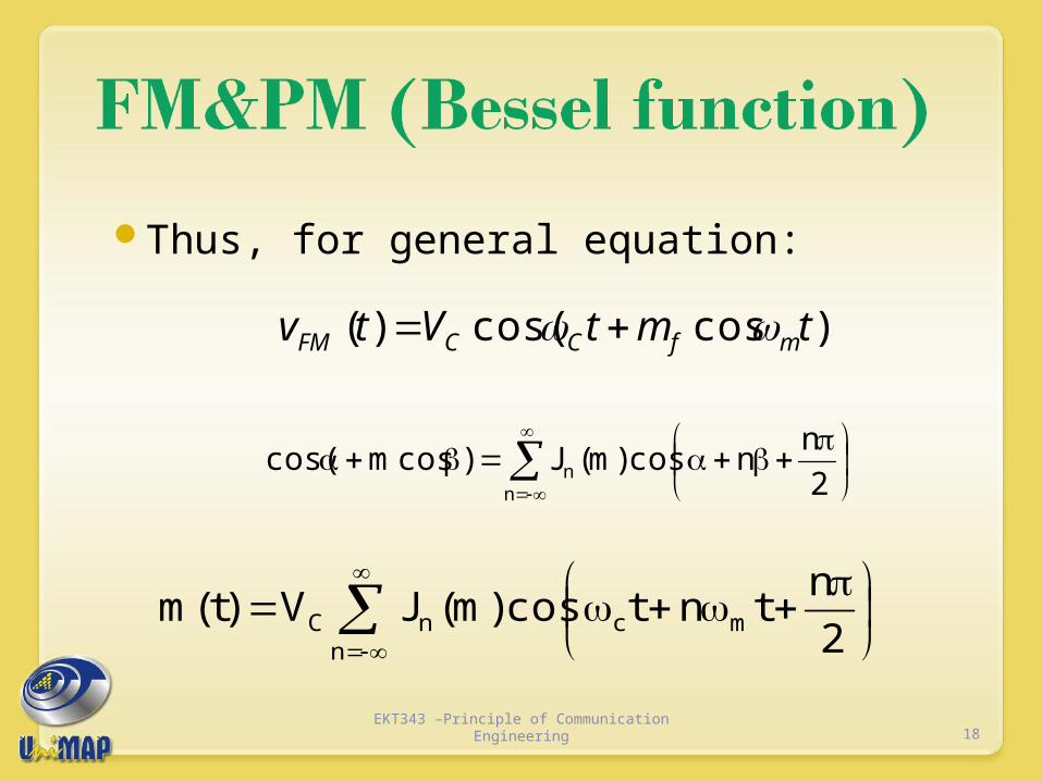
Thus, for general equation:
)coscos()( tmtVtv mfCCFM
2
nncos)m(J)cosmcos(
nn
n
mcnC 2
ntntcos)m(JV)t(m
18EKT343 –Principle of Communication
Engineering

)...}(...)2(cos)(
)2(cos)(2
)(cos)(
2)(cos)(cos)({
2
21
10
fnmCf
mCfmCf
mCfCfCFM
mJtmJ
tmJtmJ
tmJtmJVtv
19EKT343 –Principle of Communication
Engineering

It is seen that each pair of side band is preceded by J coefficients. The order of the coefficient is denoted by subscript m. The Bessel function can be written as
N = number of the side frequency Mf = modulation index
....
!2!2
2/
!1!1
2/1
2
42
n
m
n
m
n
mmJ ff
n
ffn
20EKT343 –Principle of Communication
Engineering

21EKT343 –Principle of Communication Engineering

22EKT343 –Principle of Communication
Engineering
23EKT343 –Principle of Communication
Engineering

For an FM modulator with a modulation index m = 1, a modulating signal vm(t) = Vm
sin(2π1000t), and an unmodulated carrier vc(t) = 10 sin(2π500kt). Determine the number of sets of significant side frequencies and their amplitudes. Then, draw the frequency spectrum showing their relative amplitudes.
24EKT343 –Principle of Communication
Engineering

FM BandwidthPower distribution of FM Generation & Demodulation of FMApplication of FM
25EKT343 –Principle of Communication
Engineering

Theoretically, the generation and transmission of FM requires infinite bandwidth. Practically, FM system have finite bandwidth and they perform well.
The value of modulation index determine the number of sidebands that have the significant relative amplitudes
If n is the number of sideband pairs, and line of frequency spectrum are spaced by fm, thus, the bandwidth is:
For n≥1
mfm nfB 2
26EKT343 –Principle of Communication
Engineering

Estimation of transmission b/w;Assume mf is large and n is approximate mf + 2; thusBfm=2(mf + 2)fm
=
(1) is called Carson’s rule
mm
ff
f)2(2
)1)........((2 mfm ffB
27EKT343 –Principle of Communication
Engineering

For an FM modulator with a peak frequency deviation, Δf = 10 kHz, a modulating-signal frequency fm = 10 kHz, Vc = 10 V and a 500 kHz carrier, determine
Actual minimum bandwidth from the Bessel function table.
Approximate minimum bandwidth using Carson’s rule.
Plot the output frequency spectrum for the Bessel approximation.
28EKT343 –Principle of Communication
Engineering
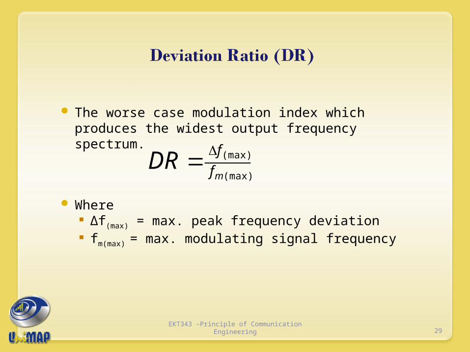
The worse case modulation index which produces the widest output frequency spectrum.
Where ∆f(max) = max. peak frequency deviation fm(max) = max. modulating signal frequency
(max)
(max)
mf
fDR
29EKT343 –Principle of Communication
Engineering

Determine the deviation ratio and bandwidth for the worst-case (widest-bandwidth) modulation index for an FM broadcast-band transmitter with a maximum frequency deviation of 75 kHz and a maximum modulating-signal frequency of 15 kHz.
Determine the deviation ratio and maximum bandwidth for an equal modulation index with only half the peak frequency deviation and modulating-signal frequency.
30EKT343 –Principle of Communication
Engineering

As seen in Bessel function table, it shows that as the sideband relative amplitude increases, the carrier amplitude,J0 decreases.
This is because, in FM, the total transmitted power is always constant and the total average power is equal to the unmodulated carrier power, that is the amplitude of the FM remains constant whether or not it is modulated.
31EKT343 –Principle of Communication
Engineering

In effect, in FM, the total power that is originally in the carrier is redistributed between all components of the spectrum, in an amount determined by the modulation index, mf, and the corresponding Bessel functions.
At certain value of modulation index, the carrier component goes to zero, where in this condition, the power is carried by the sidebands only.
32EKT343 –Principle of Communication
Engineering

The average power in unmodulated carrier
The total instantaneous power in the angle modulated carrier.
The total modulated power
R2
VP
2c
c
R2
V)]t(2t2cos[
2
1
2
1
R
VP
)]t(t[cosR
V
R
)t(mP
2c
c
2c
t
c2
2c
2
t
R
V
R
V
R
V
R
VPPPPP no
nt 2
)(2..
2
)(2
2
)(2
2..
222
21
2
210
33EKT343 –Principle of Communication
Engineering
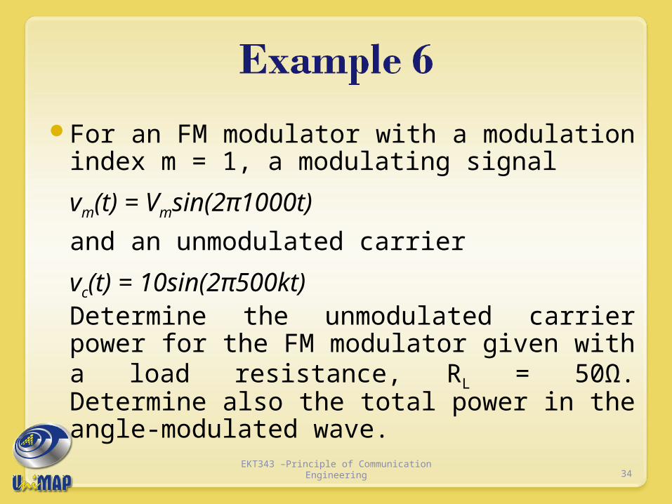
For an FM modulator with a modulation index m = 1, a modulating signal
vm(t) = Vmsin(2π1000t)
and an unmodulated carrier
vc(t) = 10sin(2π500kt) Determine the unmodulated carrier power for the FM modulator given with a load resistance, RL = 50Ω. Determine also the total power in the angle-modulated wave.
34EKT343 –Principle of Communication
Engineering
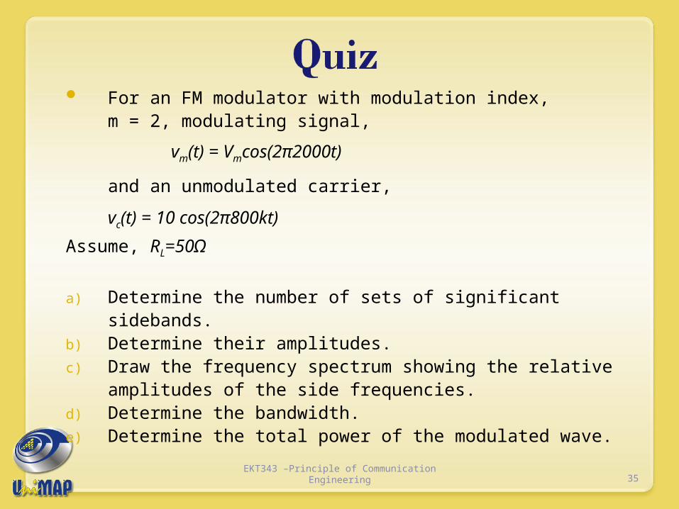
For an FM modulator with modulation index, m = 2, modulating signal,
vm(t) = Vmcos(2π2000t)
and an unmodulated carrier,
vc(t) = 10 cos(2π800kt)
Assume, RL=50Ω
a) Determine the number of sets of significant sidebands.b) Determine their amplitudes.c) Draw the frequency spectrum showing the relative
amplitudes of the side frequencies.d) Determine the bandwidth.e) Determine the total power of the modulated wave.
35EKT343 –Principle of Communication
Engineering
Two major FM generation:i) Direct method:
i) straight forward, requires a VCO whose oscillation frequency has linear dependence on applied voltage.
ii) Advantage: large frequency deviationiii) Disadvantage: the carrier frequency tends to drift and
must be stabilized.iv) Common methods:
i) FM Reactance modulatorsii) Varactor diode modulators
36EKT343 –Principle of Communication
Engineering

1) Reactance modulator
Generation of FM (cont’d)
37EKT343 –Principle of Communication
Engineering

2) Varactor diode modulator
Generation of FM (cont’d)
38EKT343 –Principle of Communication
Engineering

ii) Indirect method: i. Frequency-up conversion.ii. Two ways:
a. Heterodyne methodb. Multiplication method
iii. One most popular indirect method is the Armstrong modulator
39EKT343 –Principle of Communication
Engineering
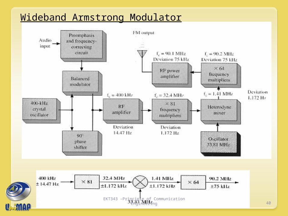
Wideband Armstrong Modulator
40EKT343 –Principle of Communication
Engineering
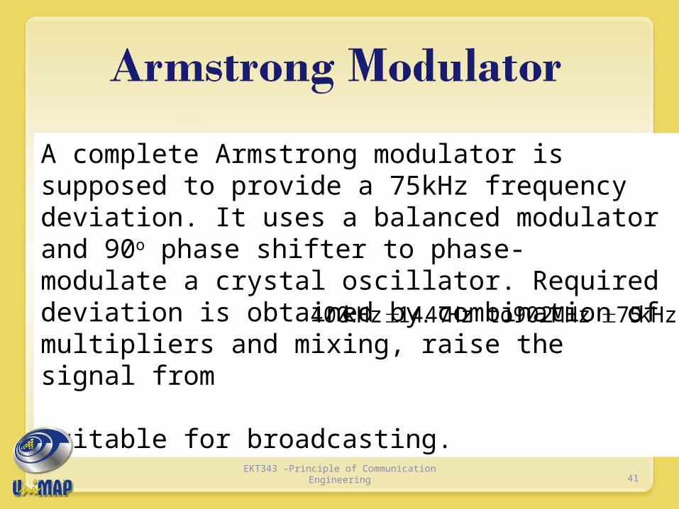
A complete Armstrong modulator is supposed to provide a 75kHz frequency deviation. It uses a balanced modulator and 90o phase shifter to phase- modulate a crystal oscillator. Required deviation is obtained by combination of multipliers and mixing, raise the signal from suitable for broadcasting.
kHz75MHz2.90toHz47.14kHz400
41EKT343 –Principle of Communication
Engineering
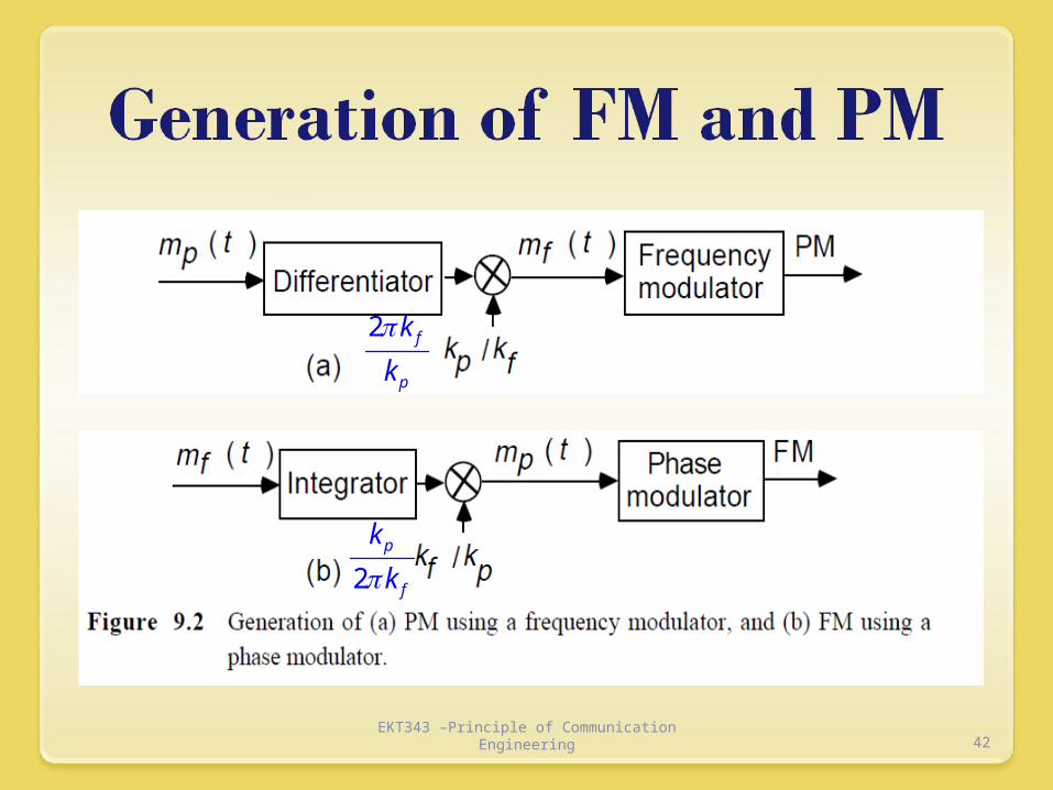
EKT343 –Principle of Communication Engineering 42
2 f
p
k
k
2p
f
k
k
FM demodulation
is a process of getting back or regenerate the original modulating signal from the modulated FM signal.
It can be achieved by converting the frequency deviation of FM signal to the variation of equivalent voltage.
The demodulator will produce an output where its instantaneous amplitude is proportional to the instantaneous frequency of the input FM signal.
43EKT343 –Principle of Communication
Engineering

To detect an FM signal, it is necessary to have a circuit whose output voltage varies linearly with the frequency of the input signal.
The most commonly used demodulator is the PLL demodulator. Can be use to detect either NBFM or WBFM.
44EKT343 –Principle of Communication
Engineering

Phase detector
VCO
Low pass filter
AmplifierFM input
Vc(t)
fvco
V0(t)
fi
45EKT343 –Principle of Communication
Engineering
The phase detector produces an average output voltage that is linear function of the phase difference between the two input signals. Then low frequency component is pass through the LPF to get a small dc average voltage to the amplifier.
After amplification, part of the signal is fed back through VCO where it results in frequency modulation of the VCO frequency. When the loop is in lock, the VCO frequency follows or tracks the incoming frequency.
46EKT343 –Principle of Communication
Engineering

Let instantaneous freq of FM Input, fi(t)=fc +k1vm(t), and the VCO output frequency, f VCO(t)=f0 + k2Vc(t); f0 is the free running frequency.For the VCO frequency to track the
instantaneous incoming frequency, fvco = fi; or ???
47EKT343 –Principle of Communication
Engineering

f0 + k2Vc(t)= fc +k1vm(t), so,
If VCO can be tuned so that fc=f0, then
Where Vc(t) is also taken as the output voltage, which therefore is the demodulated output
)()( 10 tvkfftV mcc
)()( 1 tvktV mc
48EKT343 –Principle of Communication
Engineering
The SNR can be increased without increasing transmitted power about 25dB higher than in AM
Certain forms of interference at the receiver are more easily to suppressed, as FM receiver has a limiter which eliminates the amplitude variations and fluctuations.
The modulation process can take place at a low level power stage in the transmitter, thus a low modulating power is needed.
Power content is constant and fixed, and there is no waste of power transmitted
There are guard bands in FM systems allocated by the standardization body, which can reduce interference between the adjacent channels.
49EKT343 –Principle of Communication
Engineering

In AM systems, noise easily distorts the transmitted signal however, in FM systems any added noise must create a frequency deviation in order to be perceptible.
EKT343 –Principle of Communication Engineering 50
θ
The maximum frequency deviation due to random noise occurs when the noise is at right angles to the resultant signal. In the worst case the signal frequency has been deviated by:
δ = θfm
This shows that the deviation due to noise increases as the modulation frequency increases. Since noise power is the square of the noise voltage, the signal to noise ratio can significantly degrade.
Noise occurs predominantly at the highest frequencies within the baseband
EKT343 –Principle of Communication Engineering 51

In FM systems where the signal level is well above noise received carrier-to-noise ratio and demodulated signal-to-noise ratio are related by:
= signal-to-noise ratio at output of FM demodulator = modulation index = carrier-to-noise ratio at input of FM demodulator
Does not apply when the carrier-to-noise ratio decreases below a certain point. Below this critical point the signal-to-noise ratio decreases significantly.
Known as the FM threshold effect
52EKT343 –Principle of Communication
Engineering
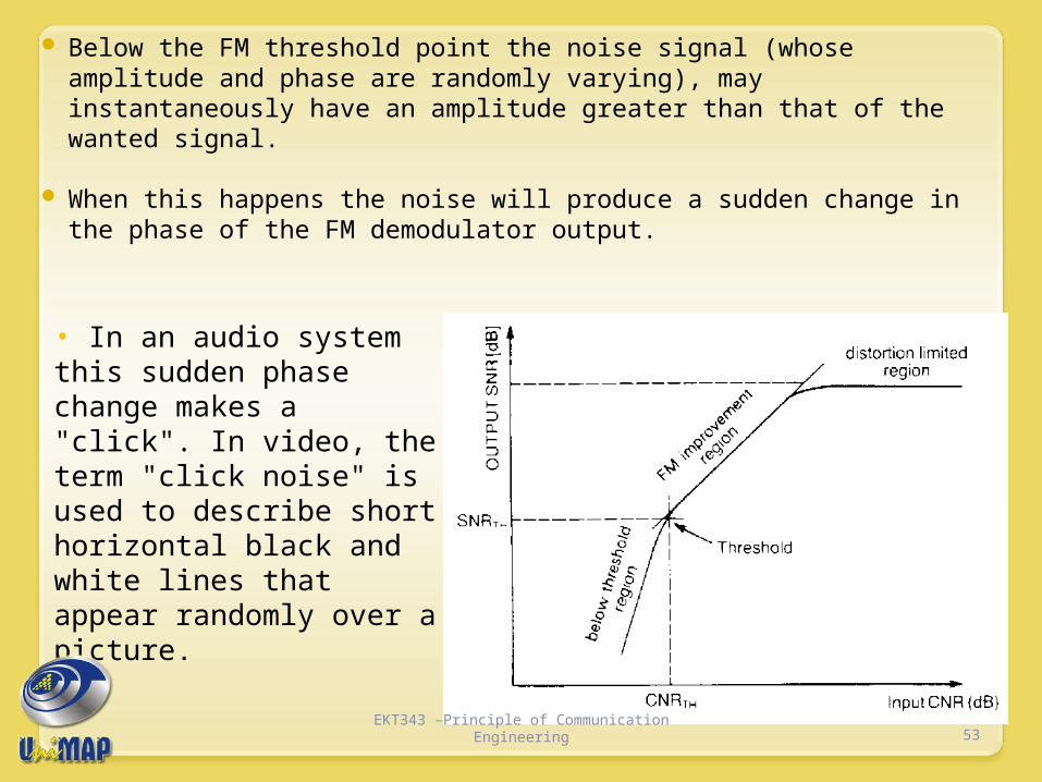
Below the FM threshold point the noise signal (whose amplitude and phase are randomly varying), may instantaneously have an amplitude greater than that of the wanted signal.
When this happens the noise will produce a sudden change in the phase of the FM demodulator output.
53EKT343 –Principle of Communication
Engineering
• In an audio system this sudden phase change makes a "click". In video, the term "click noise" is used to describe short horizontal black and white lines that appear randomly over a picture.

1. Strong nonlinearity; intentionally introduced in a controlled manner. It is introduced for particular application e.g. square law modulators, hard-limiters and frequency multipliers.
2. Weak nonlinearity; introduced because of imperfections in the communication channel. Such linearities reduce the useful signal levels.
In next slide, we will examine the effects of weak nonlinearities on FM signal
54EKT343 –Principle of Communication
Engineering

Transfer characteric of communication channel is given by
Where
We know that
EKT343 –Principle of Communication Engineering 55
)()()()( 33
221 teateateate iiio
)]()(cos[)( ttwEte cci
))()((cos
))()((cos))()(cos()(33
3
2221
ttwEa
ttwEattwEate
cc
cccco
4
3coscos3cos;
2
cos21cos 32 xx
xx
x

After filtering through bandpass filter, the fm signal output
Effect of nonlinearities: nonlinear nature of channel changes the amplitudes of the FM signal
EKT343 –Principle of Communication Engineering 56
))(3)(32cos(4
1
))(2)(22cos(2
1))()((cos
))()(2cos()4
3(
2
1)(
3
122
2
311
3
3
ttfcEa
ttfEattwEa
ttfEaEaEate
c
cccc
cccco
))()(2cos()4
3()( 3
1 3 ttfEaEate ccco
Noise is interference generated by lightning, motors, automotive ignition systems, and power line switching that produces transient signals.
Noise is typically narrow spikes of voltage with high frequencies.
Noise (voltage spikes) add to a signal and interfere with it.
Some noise completely obliterates signal information.
57EKT343 –Principle of Communication
Engineering

FM signals have a constant modulated carrier amplitude.
FM receivers contain limiter circuits that deliberately restrict the amplitude of the received signal.
Any amplitude variations occurring on the FM signal are effectively clipped by limiter circuits.
This amplitude clipping does not affect the information content of the FM signal, since it is contained solely within the frequency variations of the carrier.
58EKT343 –Principle of Communication
Engineering

Figure 5-11: An FM signal with noise. 59EKT343 –Principle of Communication
Engineering
Preemphasis Noise can interfere with an FM signal and
particularly with the high-frequency components of the modulating signal.
Noise is primarily sharp spikes of energy and contains a lot of harmonics and other high-frequency components.
To overcome high-frequency noise, a technique known as preemphasis is used.
A simple high-pass filter can serve as a transmitter’s pre-emphasis circuit.
Pre-emphasis provides more amplification of only high-frequency components.
60EKT343 –Principle of Communication
Engineering

Preemphasis circuit.
61EKT343 –Principle of Communication
Engineering

Preemphasis A simple low-pass filter can operate as a
deemphasis circuit in a receiver. A deemphasis circuit returns the frequency
response to its normal flat level. The combined effect of preemphasis and
deemphasis is to increase the signal-to-noise ratio for the high-frequency components during transmission so that they will be stronger and not masked by noise.
62EKT343 –Principle of Communication
Engineering

Deemphasis circuit.
63EKT343 –Principle of Communication
Engineering

FM is commonly used at VHF radio frequencies for high-fidelity broadcasts of music and speech (FM broadcasting). Normal (analog) TV sound is also broadcast using FM. The type of FM used in broadcast is generally called wide-FM, or W-FM
A narrowband form is used for voice communications in commercial and amateur radio settings. In two-way radio, narrowband narrow-fm (N-FM) is used to conserve bandwidth. In addition, it is used to send signals into space.
64EKT343 –Principle of Communication
Engineering
65EKT343 –Principle of Communication
Engineering

66EKT343 –Principle of Communication
Engineering

Bandwidth:a) Actual minimum bandwidth from
Bessel table:
b) Approximate minimum bandwidth using Carson’s rule:
)(2 mfnB
)(2 mffB
67EKT343 –Principle of Communication
Engineering
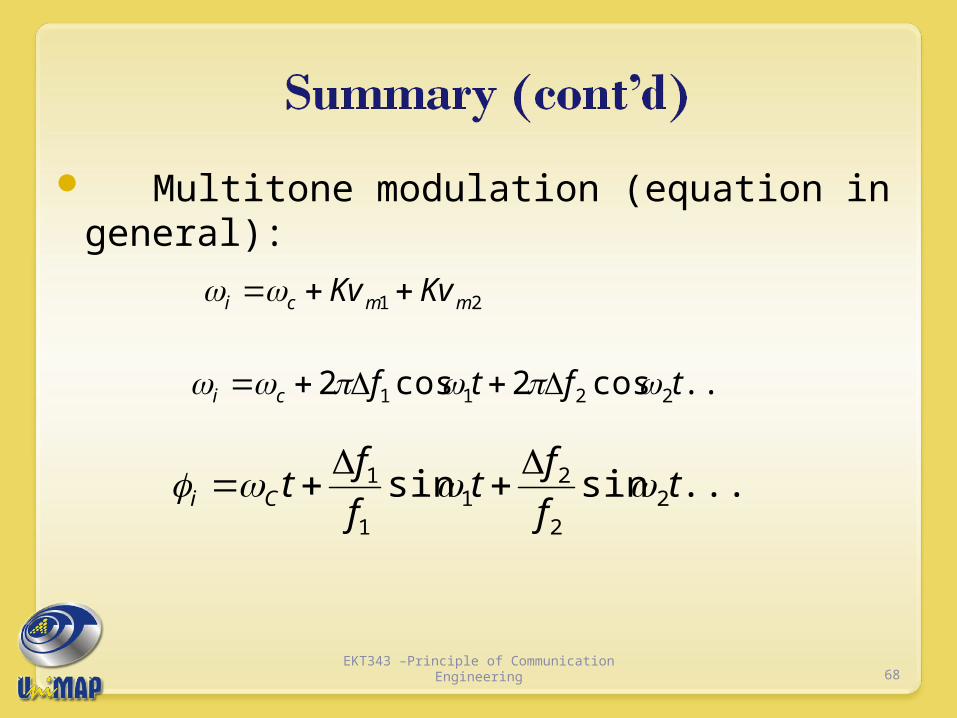
Multitone modulation (equation in general):
21 mmci KvKv
....cos2cos2 2211 tftfci
......sinsin 22
21
1
1 tf
ft
f
ftCi
68EKT343 –Principle of Communication
Engineering

..].........sinsincos[
]sinsincos[
cos
2211
22
21
1
1
tmtmtV
tf
ft
f
ftVtv
Vtv
ffCC
CCfm
iCfm
69EKT343 –Principle of Communication
Engineering

WBFM NBFM
Modulation index
greater than 10 less than 1
Freq deviation 75 kHz 5 kHz
Modulation frequency
30 Hz- 15 kHZ 3 kHz
Spectrum Infinite no of sidebands and carrier
Two sidebands and carrier
Bandwidth 15 x NBFM2(δ*fm (max))
2 fm
Noise More suppressed Less suppressed
Application Entertainment & Broadcasting
Mobile communication
70EKT343 –Principle of Communication
Engineering

Wideband FM gives significant improvement in the SNR at the output of the RX which proportional to the square of modulation index.
Angle modulation is resistant to propagation-induced selective fading since amplitude variations are unimportant and are removed at the receiver using a limiting circuit.
Angle modulation is very effective in rejecting interference. (minimizes the effect of noise).
Angle modulation allows the use of more efficient transmitter power in information.
Angle modulation is capable of handing a greater dynamic range of modulating signal without distortion than AM.
71EKT343 –Principle of Communication
Engineering

Angle modulation requires a transmission bandwidth much larger than the message signal bandwidth.
Angle modulation requires more complex and expensive circuits than AM.
72EKT343 –Principle of Communication
Engineering

END OF ANGLE MODULATION
73EKT343 –Principle of Communication
Engineering

Determine the deviation ratio and worst-case bandwidth for an FM signal with a maximum frequency deviation 25 kHz and maximum modulating signal 12.5 kHz.
74EKT343 –Principle of Communication
Engineering

For an FM modulator with 40-kHz frequency deviation and a modulating-signal frequency 10 kHz, determine the bandwidth using both Carson’s rule and Bessel table.
75EKT343 –Principle of Communication
Engineering

For an FM modulator with an unmodulated carrier amplitude 20 V, a modulation index, m = 1, and a load resistance of 10-ohm, determine the power in the modulated carrier and each side frequency, and sketch the power spectrum for the modulated wave.
76EKT343 –Principle of Communication
Engineering

A frequency modulated signal (FM) has the following expression:
The frequency deviation allowed in this system is 75 kHz. Calculate the: Modulation index Bandwidth required, using Carson’s rule
)1010sin10400cos(38)( 36 tmttv ffm
77EKT343 –Principle of Communication
Engineering