characteristics of interface between mgal2o4 spinel and
TRANSCRIPT

University of WollongongResearch Online
Faculty of Engineering and Information Sciences -Papers: Part A Faculty of Engineering and Information Sciences
2013
Characteristics of Interface between MgAl2O4Spinel and CaO-Al2O3-SiO2-MgO SlagH AbdeyazdanUniversity of Wollongong, [email protected]
M A. RhamdhaniSwinburne University
N DoganUniversity of Wollongong, [email protected]
M Chapman
B J. MonaghanUniversity of Wollongong, [email protected]
Research Online is the open access institutional repository for the University of Wollongong. For further information contact the UOW Library:[email protected]
Publication DetailsAbdeyazdan, H., Rhamdhani, M. A., Dogan, N., Chapman, M. & Monaghan, B. J. (2013). Characteristics of Interface betweenMgAl2O4 Spinel and CaO-Al2O3-SiO2-MgO Slag. Proceedings of the 3rd Indonesian Iron and Steel Conference (pp. 144-159).Bandung, Indonesia: Instutut Technologi Bandung.
Characteristics of Interface between MgAl2O4 Spinel and CaO-Al2O3-SiO2-MgO Slag
Keywordsspinel, cao, al2o3, sio2, mgal2o4, mgo, between, slag, interface, characteristics
Publication DetailsAbdeyazdan, H., Rhamdhani, M. A., Dogan, N., Chapman, M. & Monaghan, B. J. (2013). Characteristics ofInterface between MgAl2O4 Spinel and CaO-Al2O3-SiO2-MgO Slag. Proceedings of the 3rd IndonesianIron and Steel Conference (pp. 144-159). Bandung, Indonesia: Instutut Technologi Bandung.
This conference paper is available at Research Online: http://ro.uow.edu.au/eispapers/1689

3rd
Indonesian Iron and Steel Conference, Institut Teknologi Bandung, 26-27 September 2013 V.4 - hal. 144
Characteristics of Interface between MgAl2O4 Spinel and
CaO-Al2O3-SiO2-MgO Slag
H. Abdeyazdan1, M.A. Rhamdhani2, N. Dogan1, M. Chapman3, B.J. Monaghan1
1PYROmetallurgical Research Group, University of Wollongong, Australia
2HTP Group, Swinburne University of Technology, Melbourne, Australia
3BlueScope Steel, Ltd, Port Kembla, Australia
Abstract
Inclusion type and concentration in steel is critical in steelmaking, affecting both productivity
through clogging, and downstream physical properties of the steel. They are normally removed
from steel by reacting with a slag phase. For efficient inclusion removal the inclusions must
attach/bond with the slag phase. The strength of the attachment can be characterized by the
wettability of the slag on the inclusions. In this study, the interface characteristics between solid
spinel (MgAl2O4) with low porosity of 1.9% and ladle slags of the CaO-Al2O3-SiO2-MgO were
investigated, in particular the contact angle was measured at 1500 °C using a modified sessile drop
technique for different CaO/Al2O3 mass percent ratios ranging from 0.98 to 1.55. Characteristic
curves of wettability (θ) versus time showed a rapid decrease in wetting in the first 10s tending to a
plateau value at extended times. The chemical interaction at the interface between spinel
(MgAl2O4) and slag was analyzed by carrying out detailed thermodynamic evaluation and
characterization using scanning electron microscopy/energy dispersive spectroscopy (SEM/EDS).
There is evidence of the slag penetrating the substrate via pores and along grain boundaries,
forming a penetration layer on the substrate. The depth of the penetration layer was found to be a
function of cooling rate. It decreased from ~190µm to ~50µm for a slow cooled slag-spinel
substrate sample in the furnace to a rapidly cooled slag-spinel substrate sample respectively
Keywords: inclusion removal; wettability; clean steel
I. Introduction
Inclusion control and removal from steel is key in the production of high quality steel1.
Inclusions are usually formed during steel deoxidation process, though they may also
result from slag and mould flux entrainment, refractory degradation or precipitation events
on steel solidification. They are generally removed to the slag phase2. In the removal
process the inclusions contact and bond/react with the slag phase then dissolve in the
slag. If the bond is weak, then local fluid conditions are likely to result in the shearing of
the inclusion-slag bond and the inclusions remain in the steel. The strength of the
inclusion bond or reactivity with slag may be assessed by measuring the dynamic wetting

3rd
Indonesian Iron and Steel Conference, Institut Teknologi Bandung, 26-27 September 2013 V.4 - hal. 145
of the slag on a substrate made of the inclusion phase3. Research on inclusion removal in
steel refining is principally divided into categories of flotation of inclusion to the steel/slag
interface4-5, modification to improve reactivity/separation with the slag phase6 and
dissolution in the slag phase7-13.
A number of studies relevant to inclusion dissolution in slags have been carried out on
bulk refractory or ceramic materials14-18 where the material is dipped in slag and held for a
period of time, removed, then analyzed for slag corrosion and/or penetration. Some recent
studies have used high temperature microscopy offering the possibility of analyzing the
dissolution behavior of a single inclusion in a slag directly 7-13. Monaghan and Chen7 and
Valdez et al.12 used high temperature microscopy to investigate the effect of slag basicity
on spinel inclusion dissolution. They found that the rate of dissolution of the spinel
particles increased with increasing basicity of the slag.
While it is understood that inclusion-slag interfacial tension/wetting play a critical role in
inclusion removal, there are limited data of slags on typical inclusion phase types in the
literature. Recently the current authors3 have investigated dynamic contact angle () of
slags in the CaO-Al2O3-SiO2-MgO system on a ceramic representing an MgAl2O4 spinel-
type inclusion using the sessile drop technique. For slags with CaO/Al2O3 mass ratios,
noted C/A, of between 0.98 and 1.55, it was found that over the first 30 seconds of contact
of the slag on spinel substrate that rapidly decreased from ~40° to ~15°. Further, there
was not a clear relationship between and the C/A of the slag and that the slag
penetrated the spinel substrate. The spinel substrates used had a high porosity of ~6.7%.
It was not clear if the penetration was simply a result of the relatively high porosity sample
and/or a function of the time the samples spent in the furnace. More specifically did the
slag penetration happen during the measurement or as a result of the slag/substrate
remaining in the hot zone of the furnace as it cooled.
To address the uncertainty due to porosity/penetration issues the dynamic contact angles
reported in 6.7% study3 have been repeated using higher density spinel substrates.
II. Experimental
A schematic of the modified sessile drop apparatus used to measure the contact angle in
this study is given in Figure 1. The slag and substrate were heated separately to 1500 °C,
the experimental temperature, under high purity of (99.99%) argon at a flow rate of 0.75
l/min. The gas was scrubbed by passing through ascarite and drierite prior to entering the
furnace. Once the temperature has stabilised (~10 minutes) the slag is added to the spinel
substrate. A novel method of place the slag on the surface of the ceramic substrate has

3rd
Indonesian Iron and Steel Conference, Institut Teknologi Bandung, 26-27 September 2013 V.4 - hal. 146
been developed. The solid slag is held in the Pt wire loop (number 4 in Figure 1). As it
melts and becomes liquid it remains held in the Pt wire by interfacial forces until thermal
stabilization is reached. The slag is then contacted/added to the substrate. This technique
allows the addition of slag in liquid state at the target temperature and avoids the
uncertainty of the time zero of the experiment (starting point of experiment).
Prior to carrying out the experiment the substrate was levelled in the furnace using an
alignment laser. This is critical to minimise gravity affects distorting the liquid. To start the
experiment, the alumina support rod (number 3 in Figure 1) was lowered so that the slag
contacted the MgAl2O4 substrate. The moment at which the liquid slag is contacted to the
substrate and separated from the Pt wire is defined as zero time. Approximately 0.1g of
slag from an original 0.2 g was transferred to the substrate. The mass of slag added
represents a compromise between errors associated with scale at small masses and
using a mass that is less than the critical value of that required for gravity distortions of the
droplet20. Once the slag is added the twin bore tube, alumina support and Pt wire were
withdrawn to a cold part of the furnace chamber. The spreading of the slag on the
substrate was recorded with a Sony 6.1 MP video camera (HDR-SR7E). The camera was
fitted with a 2x telephoto lens and 2 HOYA neutral density filters (NDX4 and NDX400) in
series. At the end of the experiment, after ~15 minutes at the experimental temperature
after time zero, the slag and substrate were cooled in the furnace at a rate of ~7°C/min.
Figure 1 - A schematic of the sessile drop apparatus. 1: Pt Wire, 2: Twin bore tube, 3:
Alumina support, 4: Liquid slag held by Pt wire, 5: Spinel substrate, 6: Tray and block, 7:
Resistance furnace, 8: Inlet gas, 9: Outlet gas, 10: Camera, 11: 2x telephoto lens, 12:
Filters, 13: Quartz window, 14: Monitor, 15: Flange
The contact angle (θ) was calculated using equation (1) and the geometry of a spherical
cap as shown in Figure 2 20 from digital still images captured from the recordings,
θ
(1)
Gambar 13: Coke Oven
Battery G

3rd
Indonesian Iron and Steel Conference, Institut Teknologi Bandung, 26-27 September 2013 V.4 - hal. 147
where R is the radius dissected by a base plane, h is the height of contact circle and a is
radius of contact circle.
Figure 2 - Geometry of a sessile drop approximated by a spherical cap defined by radius
of the base and height above basal plane.
The slags used were prepared by mixing laboratory grade oxides (CaO, Al2O3, SiO2 and
MgO) of appropriate proportions. These mixtures were then melted in a platinum crucible,
quenched and crushed. This process was repeated twice to ensure slag homogeneity.
Compositions of the resultant slag, as measured by XRF, are given in Table 1. C/A
represents the mass% ratio of CaO/Al2O3. From these slags, 0.2g sintered pellets were
prepared and used in the sessile drop experiments.
Table 1: Chemical composition of the experimented slags in mass%
Slag CaO Al2O3 SiO2 MgO C/A
1 41.8 42.7 9.2 6.3 0.98
2 46.3 37.1 9.8 6.8 1.25
3 50.9 32.9 9.5 6.7 1.55
The MgAl2O4 spinel powders were prepared from high purity laboratory grade MgO and
Al2O3 (> 99%) starting materials by reaction sintering. These were mixed and then
pressed into pellets and sintered at 1600 ˚C for 24 hours. This sintered material was then
crushed to a fine powder (< 38µm) and re-sintered at 1725 ˚C for 6 hours. After the
second sintering, the spinel phase was confirmed by X-ray diffraction (XRD). No other
phases were identified via XRD. The substrates were then polished to 1µm for the sessile
drop experiments. The substrates had an average apparent porosity21 of 1.9% and a
spinel composition of 71.7% Al2O3 and 28.3% MgO in mass%. Post experiment the
sample was sectioned and prepared for electro-optical analysis. A JEOL–JSM6490 LV
scanning electron microscopy (SEM) with energy dispersive spectroscopy (EDS) was

3rd
Indonesian Iron and Steel Conference, Institut Teknologi Bandung, 26-27 September 2013 V.4 - hal. 148
used. To assess the effects of time/cooling on penetration of the slag into the spinel
substrate a further experiment was carried out using slag with a C/A ratio of 0.98. In this
experiment the slag was added similarly the previous experiments. The primary difference
was that 30 seconds after time zero, the furnace was opened and the slag-substrate
couple was removed and left to rapidly cool in air on a laboratory bench. All other
experimental conditions were the same as outlined for the furnace cooled samples. The
total time this slag the slag-substrate couple remained in the hot zone of the furnace was
~60 s.
III. Results and Discussion
Figure 3 shows a typical example of the spreading and wetting behavior of a liquid slag
drop on a spinel substrate is shown. It can be seen that the liquid drop spreads out on the
substrate within a few seconds.
The results of the wetting behaviour for the slags are given in Figure 4. The data
presented represent an average of a minimum of two runs per C/A ratio tested. The θ
decreased from 37.7°, 28.7° and 27° at time zero for the C/A 0.98, C/A 1.25 and C/A 1.55
slags respectively to a slag C/A ratio independent value. After 30s, at the end of the
experiment, the θ was ~18.1°. This value represents an average of all data reported. It
would appear the rate of θ change in the early part of the experiment decreases with
increasing C/A ratio. The significant drop in θ in the first 6s is consistent with the previous
work the authors have reported on the higher porosity spinel material3 and similar to what
other workers found for CaO-SiO2-Al2O3 based slags on alumina22. The initial drop in θ is
likely to be principally due to the reaction of the slag with the substrate it may also contain
a momentum component due to the slag addition technique.
t = -22 s t = -2 s t = -1 s t = 0 s
t = 1 s t = 2 s t = 3 s t = 4 s
t = 5 s t = 10 s t = 20 s t = 30 s
Figure 3: Spreading behaviour of the slag C/A 1.25 on the spinel substrate.

3rd
Indonesian Iron and Steel Conference, Institut Teknologi Bandung, 26-27 September 2013 V.4 - hal. 149
Figure 4: θ versus time measured for slags of different C/A ratios on a spinel substrate.
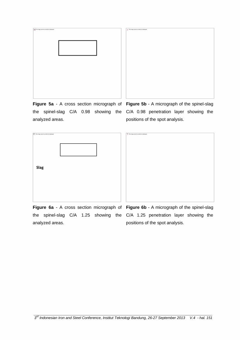
SEM characterization of the interface is given in Figures 5a, 6a and 7a for the C/A 0.98,
C/A 1.25 and C/A 1.55 slags respectively. Inspection of these figures shows a slag
penetration layer at the interface between the slag and spinel substrate. Given the
changes in θ it is likely this layer in part represents reaction between the slag and spinel
substrate. It is also likely to contain a reactivity/penetration component that is associated
with the cooling down period of the experiment. EDS analysis of the areas marked in
Figures 5a to 7a are given in Table 2. EDS spot analyses of the penetration layer shown
in Figures 5b, 6b and 7b are given in Table 3.
Table 2: EDS analysis of areas in Figures 5a, 6a and 7a. Values are in mass%
C/A Location/Phases CaO Al2O3 SiO2 MgO
0.98
Slag 43.3 41.7 9.0 6.0
Penetration zone 6.3 65.4 3.4 24.9
Spinel substrate 0.4 71.6 2.8 25.2
1.25
Slag 41.9 41.7 8.2 8.2
Penetration zone 6.0 67.0 2.6 24.4
Spinel substrate 0.2 72.0 2.8 25.0
1.55
Slag 44.0 42.0 6.6 7.4
Penetration zone 6.3 66.2 3.1 24.4
0
5
10
15
20
25
30
35
40
45
50
0 2 4 6 8 10 12 14 16 18 20 22 24 26 28 30
Co
nta
ct a
ngl
e (
de
g)
time (sec)
C/A=0.98 C/A=1.25 C/A=1.55
3rd
Indonesian Iron and Steel Conference, Institut Teknologi Bandung, 26-27 September 2013 V.4 - hal. 150
Spinel substrate 0.4 71.9 2.9 24.8
Table 3: EDS spot analysis of phases in Figures 5b, 6b and 7b. Values are in mass%
C/A Location/Phases CaO Al2O3 SiO2 MgO
0.98 Spinel (grey phases) 0.1 69.7 2.6 27.6
Slag penetration (White phase) 42.6 47.0 7.6 2.8
1.25 Spinel (grey phases) 0.2 70.3 2.5 27.0
Slag penetration (White phase) 36.7 58.4 2.1 2.8
1.55 Spinel (grey phases) 0.2 69.6 2.6 27.6
Slag penetration (White phase) 43.0 41.2 9.9 5.8
From these data it would appear that the slag C/A 1.25 and 1.55 has become depleted of
CaO and enriched with Al2O3. The composition of slag C/A 0.98 is similar to the starting
slag composition given in Table 1. In the slag penetration layer there appears to be two
phases. A dark phase representing something close to the original spinel and a white
phase that most likely represents slag penetration into the spinel. From Figures 5b, 6b
and 7b it would appear the slag is penetrating through pores and along the grain
boundaries.
Thermodynamic analysis of the slag-spinel substrate systems has also been carried out
using MTData19 and the isopleths representing spinel substrate-slag C/A 0.98 and 1.55
are given in Figures 8a and 8b respectively. From Figure 8a it can be seen that at the
experimental temperature (1500 oC) the spinel phase and oxide liquid (slag) phase are
stable. In Figure 8b for the C/A 1.55 slag, spinel phase, oxide liquid (slag) and halite
(MgO) phases are stable. The phases predicted are broadly consistent with the EDS
analysis of the penetration layer that showed a two phase region. The darker phase being
consistent with the original spinel and the white phase being consistent with the oxide
liquid (slag) phase. To understand why no halite (MgO) phase has been identified as
predicted in Figure 8b for the C/A 1.55 slag requires more detailed analysis.
3rd
Indonesian Iron and Steel Conference, Institut Teknologi Bandung, 26-27 September 2013 V.4 - hal. 151
Figure 5a - A cross section micrograph of
the spinel-slag C/A 0.98 showing the
analyzed areas.
Figure 5b - A micrograph of the spinel-slag
C/A 0.98 penetration layer showing the
positions of the spot analysis.
Figure 6a - A cross section micrograph of
the spinel-slag C/A 1.25 showing the
analyzed areas.
Figure 6b - A micrograph of the spinel-slag
C/A 1.25 penetration layer showing the
positions of the spot analysis.
Slag
Penetration layer
Spinel substrate
Spinel (grey phase)

3rd
Indonesian Iron and Steel Conference, Institut Teknologi Bandung, 26-27 September 2013 V.4 - hal. 152
Figure 7a - A cross section micrograph of
the spinel-slag C/A 1.55 showing the
analyzed areas.
Figure 7b - A micrograph of the spinel-slag
C/A=1.55 penetration layer showing the
positions of the spot analysis.
White phase
Slag
Penetration layer
Spinel substrate
Spinel (grey phase)
White

3rd
Indonesian Iron and Steel Conference, Institut Teknologi Bandung, 26-27 September 2013 V.4 - hal. 153
Figure 8: The MTData19 thermodynamic calculation showing the phase stability in the (a)
spinel-slag C/A 0.98 and (b) spinel-slag C/A 1.55 systems. The associated phase fields
are shown in table below.
Phase field Phases present
A MELILITE + SPINEL
B OXIDE_LIQUID + MELILITE + SPINEL
C OXIDE_LIQUID + MELILITE + SPINEL + CA
D MELILITE + SPINEL + CA + ALPHA_PRIME_C2S
E SPINEL + CA + ALPHA_PRIME_C2S
F OXIDE_LIQUID + MELILITE + SPINEL+ ALPHA_PRIME_C2S
G OXIDE_LIQUID + SPINEL + CA + ALPHA_PRIME_C2S
H C3A2M + SPINEL + CA + ALPHA_PRIME_C2S
I OXIDE_LIQUID + SPINEL + ALPHA_PRIME_C2S
J C3A2M + OXIDE_LIQUID + SPINEL + ALPHA_PRIME_C2S
K OXIDE_LIQUID + HALITE
L OXIDE_LIQUID + ALPHA_PRIME_C2S
M OXIDE_LIQUID + ALPHA_PRIME_C2S + HALITE
N C3A2M + SPINEL + ALPHA_PRIME_C2S
O OXIDE_LIQUID + ALPHA_C2S + HALITE

3rd
Indonesian Iron and Steel Conference, Institut Teknologi Bandung, 26-27 September 2013 V.4 - hal. 154
P C3A2M + OXIDE_LIQUID + ALPHA_PRIME_C2S + HALITE
Q OXIDE_LIQUID + C3A + ALPHA_PRIME_C2S + HALITE
R C3A2M + C3A + ALPHA_PRIME_C2S + HALITE
A more detailed thermodynamic analysis of the phases formed at 1500 oC for the C/A 1.55
is given in Figure 9. From Figure 9 it can be seen that, for mass ratios of MgAl2O4 to slag
up to ~0.76, the amount of spinel is linearly decreasing and inversely proportional to the
liquid oxide phase. After this point it is primarily liquid oxide that is stable. The amount of
halite (MgO) phase predicted to form, shown in Figure 9, reached a maximum of ~ 0.6%
by mass and was only stable over a very limited spinel slag mixture range. Given this
small value and the limitations of EDS analysis it is not surprising that the MgO phase was
not found in the penetration layer of the C/A 1.55 slag.
Figure 9: MTData19 thermodynamic calculations showing the mass of phases present at
different MgAl2O4 to slag C/A 1.55 mass ratios at 1500 ˚C, where 2 = oxide liquid, 8 =
spinel and X2 = halite.

3rd
Indonesian Iron and Steel Conference, Institut Teknologi Bandung, 26-27 September 2013 V.4 - hal. 155
Figure 10: MTData19 thermodynamic calculations showing the mass fraction of
components in the liquid oxide phase at different MgAl2O4 to slag C/A 0.98 mass ratios at
1500 ˚C where 1=CaO, 2=Al2O3, 3=SiO2, 4=MgO.
Figure 11: MTData19 thermodynamic calculations showing the mass fraction of
components in the liquid oxide phase at different MgAl2O4 to slag C/A 1.55 mass ratios at
1500 ˚C where 1=CaO, 2=Al2O3, 3=SiO2, 4=MgO.
The change in mass fraction of the slag components (change in slag composition) of all
the stable phases at 1500 ˚C for three slag-spinel substrate systems was also evaluated

3rd
Indonesian Iron and Steel Conference, Institut Teknologi Bandung, 26-27 September 2013 V.4 - hal. 156
using MTData19. There was little change predicted in the composition of the spinel and
halite phases, as such they are not reproduced here. The slag phase however, and in
particular the slag phase in the C/A 1.55 slag-spinel system, was predicted to change (see
Figures 10 to 11). From the thermodynamic analysis it was expected that there would be
an increase in the Al2O3 of the slags and a decrease in the CaO of the slag. These
changes being modest in C/A 0.98 slag (Figure 10) but increasing with C/A ratio of the
slag (Figure 11). This is broadly consistent with the slag analysis given in Tables 1 and 2.
Though the C/A 0.98 slag showed little change in the slag composition (Tables 1 and 2)
before and after the experiment, this is likely due to uncertainties in the EDS analysis, a
lower driving force for reaction as the Al2O3 and CaO contents of the slag are close to the
equilibrium values or some combination of both.
IV. Effect of Cooling Time on the Penetration Layer
Comparison of the of slag-substrate interface at the end of the experiment under the two
different cooling regimes (slow cooled in the furnace vs. rapid cooled on the bench top) is
given in Figure 12 for the C/A/ 0.98 slag. From Figure 12a and 12b it can be seen that
there is a decrease in the depth of slag penetration from ~190 µm to ~50µm for the slow
and rapid cooled samples respectively. A higher magnification image of the area marked
with a dashed box in Figure 12b, showing the slag penetration is given in in Figure 12c.
Also shown in Figure 12c are the positions of the EDS spot analyses for the spinel (grey
phase) and slag (white phase). The respective EDS compositions are given in Table 4.
The composition of the dark phase represents something close to the original spinel and
the white phase is similar to that of the starting slag but is enriched of alumina and
depleted of magnesia.
From these data it can be seen that the slag is penetrating/reacting with the spinel
substrates even at the short timescales. This is likely to be significant for inclusion
removal, where an inclusion has to bond/react with the slag prior to its dissolution in the
slag. It is likely this penetration would lead to a stronger bond with the slag and therefore
more efficient removal from the liquid steel.

3rd
Indonesian Iron and Steel Conference, Institut Teknologi Bandung, 26-27 September 2013 V.4 - hal. 157
Figure 12a: The thickness of the
penetration layer for C/A 0.98 slag under
standard measurement conditions and
(slow) cooled in the furnace.
Figure 12b: The thickness of the
penetration layer for C/A 0.98 slag where
the sample was removed from the furnace
in ~60 seconds after time zero and (rapid)
cooled on laboratory bench.
Figure 12c - A higher magnification image
of the dashed area marked in Fig 12b,
showing the slag penetration and the
positions of spot analysis for the spinel-
slag C/A 0.98.
Table 4: EDS spot analysis of phases in Figures 12c. Values are in mass%
Location/Phases CaO Al2O3 SiO2 MgO
Spinel (grey phases) 0.1 69.7 2.6 27.6
Slag penetration (White phase) 42.6 47.0 7.6 2.8
phasePenetration layer thickness
Slag
Penetration layer
Spinel substrate
Spinel (gray phase)
White phase
(a)
White
(b)

3rd
Indonesian Iron and Steel Conference, Institut Teknologi Bandung, 26-27 September 2013 V.4 - hal. 158
V. Conclusions
In a study to investigate slag reactivity with inclusions, a series of dynamic wetting
measurements and thermodynamic analysis of slags in the CaO-Al2O3-SiO2-MgO system
on a MgAl2O4 spinel substrate was carried out. The key findings were
The contact angle (θ) of the slag on the substrate decreases rapidly in the first 10s to
a plateau value at extended times. The contact angle (θ) decreased from 37.7°, 28.7°
and 27° at time zero for the C/A 0.98, C/A 1.25 and C/A 1.55 slags respectively to a
slag concentration independent value. After 30s, at the end of the experiment, this
value was ~18.1°. This value represents an average of all data reported.
There was evidence of the slag penetrating the substrate via pores and along grain
boundaries, forming a reaction/penetration layer on the substrate. From SEM and
EDS analysis this penetrated layer appeared two phase and consisted of something
close to the original spinel and a modified slag phase. This was very similar to
previous work by the authors on a higher porosity spinel. It would appear at the
porosity levels studied 6.7 in the previous work and 1.9% in this work the penetration
effects are not a strong function of porosity.
Thermodynamic modelling of the slag-spinel substrate system was broadly consistent
with the EDS analysis of the penetrated layer and post reacted slag.
The thickness of penetration layer decreased from approximately 190µm to 50µm
when the cooling time reduced from 15 min to ~1 min but there is still a
reactivity/penetration layer for short contact period in the low porosity (1.9%) spinel.
V. Acknowledgment
The support of BlueScope Steel and the use of the Australian Research Council funded
JEOL–JSM6490 LV SEM at the UOW Electron Microscopy Centre is acknowledged.
References
1. J.H. Lowe and A. Mitchell: Clean Steel, Institute of Materials, London, (1995), 223.
2. B. Deo and R. Boom: Fundamentals of Steelmaking Metallurgy, Prentice Hall
International, New York, (1993), 254.
3. H. Abdeyazdan, B.J. Monaghan, N. Dogan and M.A. Rhamdhani: High Temperature
Processing Symposium, (2013), 44.
4. L. Jonsson and P. Jönsson: ISIJ International, 36(1996), 1127.
5. L. Zhang, S. Taniguchi and K. Matsumoto: Ironmaking & Steelmaking, 29(2002), 326.
6. Y. Miki, H. Kitaoka, T. Sakuraya and T. Fujii: ISIJ International, 32(1992), 142.

3rd
Indonesian Iron and Steel Conference, Institut Teknologi Bandung, 26-27 September 2013 V.4 - hal. 159
7. B.J. Monaghan and L. Chen: Ironmaking and Steelmaking, 33(2006), 323.
8. B.J. Monaghan, L. Chen and J. Sorbe: Ironmaking & Steelmaking, 32(2005), 258.
9. K. H. Sandhage & G. J. Yurek: Journal of American Ceramic Society, 74(1991), 1941.
10. S. Sridhar & A.W. Cramb: Metallurgical and Materials Transactions B, 31(2000), 406.
11. M. Valdez, K. Prapakorn, A.W. Cramb & S. Seetharaman: Steel Research, 72(2001),
291.
12. M. Valdez, K. Prapakorn, A.W. Cramb & S. Sridhar: Ironmaking and Steelmaking,
29(2001), 47.
13. X. Yu, R.J. Pomfret & K.S. Coley: Metallurgical and Materials Transactions B,
28(1997), 275.
14. K.H. Sandhage & G.J. Yurek: Journal of American Ceramic Society, 71(1988), 478.
15. K.H. Sandhage & G.J. Yurek: Journal of American Ceramic Society, 73(1990), 3633.
16. K.H. Sandhage & G.J. Yurek: Journal of American Ceramic Society, 73(1990), 3643.
17. S. Taira, K. Nakashima & K. Mori: ISIJ International, 33(1993), 116.
18. K. Ueda: Materials Transactions-JIM, 40(1999), 989.
19. R.H. Davies, A.T. Dinsdale, J.A. Gisby, J. Robinson & S.M. Martin: Calphad, 26(2002),
229.
20. N. Eustathopoulos, M.G. Nicholas and B. Drevet: Wettability at high temperatures,
Elsevier, (1999), 106.
21. A. 1774.5 Method 5: The Determination of Density Porosity and Water Adsorption in
Refractories and Refractory Materials, Standards Australia, (2004).
22. J.Y. Choi and H.G. Lee: ISIJ International, 43(2003), 1348.
Curriculum Vitae
Crystalline slag