characterization of the effects of the turbulence on the propagation of a laser beam ... ·...
TRANSCRIPT

a Corresponding author: [email protected]
Characterization of the effects of the turbulence on the propagation of a laser beam in air Zucco M1, Pisani M1 and Astrua M1 1INRiM, Torino, Strada delle Cacce 91, Italy
Résumé. Les mesures de longues distances sont fortement influencées par les effets de turbulence et de gradients de température. Le sujet de cet article est la description du système développé au INRiM pour enquêter sur ces effets. Le système est composé de deux parties distinctes: la première partie consacrée à la mesure de la phase de fluctuation causé par la turbulence est constituée par un interféromètre de longueur d'onde synthétique où les deux bras sont formées par deux faisceaux parallèles à une distance variable en plein air; la deuxième partie, pour mesurer le mouvement de faisceau, est composée d'un faisceau d’un laser He-Ne envoyé à une caméra CCD et à un PSD (détecteur sensible à la position). Les premiers résultats préliminaires obtenus dans des conditions de laboratoire et en plein air, sont décrites
.
1 Introduction The most accurate measurements of long distances are usually performed by means of optical methods, i.e. exploiting the propagation of a laser beam through the air. Anyway, the propagation of a laser beam in air is influenced by turbulence effects and by gradients of temperature caused by thermal exchanges with the ground and the sun’s heating. As a consequence, the beam wanders and random fluctuations of amplitude, intensity, phase and angle-of-arrival occur, causing unavoidable errors in the distance measurement [1,2]. In the framework of the project EMRP SIB60, aimed at improving the traceability of long distance measurements, a device to characterize these effects is under development at INRIM. It is composed of 2 main different set-ups. The first one is composed of a synthetic wavelength interferometer where the two arms are formed by two parallel beams at a variable distance in open air. By changing the distance between the arms and measuring the relative phase fluctuation between the two transmitted beams it could be possible to estimate the dimension of the vortices of the turbulence and the kind of noise associated to the fluctuation. The second device aims to measure the beam wandering and the wavefront distortion. A He-Ne laser is sent to a receiver composed of a CCD camera and a position sensitive detector (PSD). The PSD measures the position of the laser center of mass, in order to obtain a fast analysis of the beam wandering. The CCD captures the
images of the beam at a lower rate and allows to analyse the distortion of the wavefront.
2 Experimental set-up
2.1 Parallel beams In this experiment we have modified the interferometer developed for the measurement of absolute distance in air and based on the synthetic wavelength technique with a superheterodyne detection system [3]. This interferometer is based on two extended cavity diode lasers at 1542 nm whose frequency difference can be tuned continuously without mode jumps by means of the laser temperature control from zero to a frequency difference of about 40 GHz in order to calculate the absolute distance. The synthetic frequency is measured directly by sending the two radiations to a fast detector. A phase locked loop (PLL) system acting on the PZT of one laser is used to lock the laser frequency difference to a synthesizer referenced to the local realization of the SI second, assuring in this way the traceability of the absolute distance measurement to the SI metre. The displacement information is contained in the phase of the synthetic frequency that is too high to be measured by the electronics; the super-heterodyne detection scheme consists in down-converting the frequency to the kilohertz level maintaining the phase information. The
DOI: 10.1051/C© Owned by the authors, published by EDP Sciences, 2015
2015metrolo /gy17 International Congress of Metrology, 1 01 (20 5 )
th1
1 03
3 1
This is an Open Access article distributed under the terms of the Creative Commons Attribution License 4.0, which permits unrestricted use, distribution, and reproduction in any medium, provided the original work is properly cited.
44
Article available at http://cfmetrologie.edpsciences.org or http://dx.doi.org/10.1051/metrology/20150013014

two detectors are followed by two mixers to extract the signals at the super-heterodyne frequency which in our set-up is fixed at 120 kHz. The two signals are then acquired by a parallel ADC board with a sampling rate of 800 kHz. The phase measurement is carried out by a Labview program that implements the I/Q modulation and gives the phase difference Φ between the two synthetic frequencies. We have measured the power spectral density of the displacement of our interferometer and the results are presented in figure 1 where the black curve is the noise limit measured by short-circuiting the measuring arm, the green and blue curves are the power spectral density obtained by placing the retroreflector at 78 and 137 m respectively.
Figure 1. power spectral density of the displacement of our interferometer measured with a synthetic frequency equal to 20 GHz Thanks to the good resolution performances of our interferometer we decided to modify the interferometer scheme into the one represented in Figure 2 where also the reference arm in launched to air. The aim is to measure the fluctuation of displacement between the two arms that would correspond to the effect of the turbulence of air.
Figure 2. Optical set-up of the modified interferometer to measure the effects of fluctuation of air The two launchers and the two reflectors are mounted on two different linear stages, as it can be clearly visible in
the following figure 3, in this way it is possible to change the lateral distance of the beams from a minimum of about 10 cm to a maximum of about 1 m and measure the fluctuation for different distances of the laser beams.
Figure 3. retro-reflectors (a) and fiber launchers (b) mounted on a stage with a distance that can vary from 10 cm to about 1 m.
2.2 CCD camera and position sensitive detector
The second set-up is composed of a diode laser beam sent to a receiver formed by a CCD camera and a PSD, as shown in figure 4. The source is a diode laser at about 635 nm launched by a fixed focus collimator. The laser power is selectable up to about 20 mW and the beam dimension is approximately 7 mm. The signals coming from the PSD are acquired by a ADC board (NI USB-6210) at a selectable frequency up to 1 kHz, in order to measure the x and y position of the laser center of mass. This set up aims at following the fast movements of the beam caused by the air turbulence. On the other hand, the CCD captures the images of the laser beam at a lower rate (1 frame per second) in order to follow the slow movements of the beam (such as the diurnal cycle of temperature). A program implemented in Labview captures the image of the laser spot on the CCD, perform a Gaussian fit and measures the position of the spot center. Moreover, this set-up allows to analyse the distortion of the wavefront induced by air turbulence.
a)
b)
Web of Conferences
13014-p.2
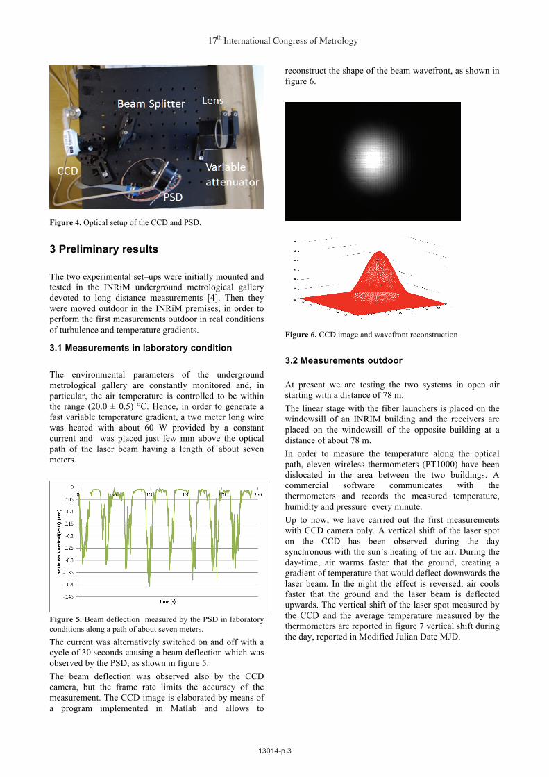
Figure 4. Optical setup of the CCD and PSD.
3 Preliminary results
The two experimental set–ups were initially mounted and tested in the INRiM underground metrological gallery devoted to long distance measurements [4]. Then they were moved outdoor in the INRiM premises, in order to perform the first measurements outdoor in real conditions of turbulence and temperature gradients.
3.1 Measurements in laboratory condition The environmental parameters of the underground metrological gallery are constantly monitored and, in particular, the air temperature is controlled to be within the range (20.0 ± 0.5) °C. Hence, in order to generate a fast variable temperature gradient, a two meter long wire was heated with about 60 W provided by a constant current and was placed just few mm above the optical path of the laser beam having a length of about seven meters.
Figure 5. Beam deflection measured by the PSD in laboratory conditions along a path of about seven meters. The current was alternatively switched on and off with a cycle of 30 seconds causing a beam deflection which was observed by the PSD, as shown in figure 5. The beam deflection was observed also by the CCD camera, but the frame rate limits the accuracy of the measurement. The CCD image is elaborated by means of a program implemented in Matlab and allows to
reconstruct the shape of the beam wavefront, as shown in figure 6.
Figure 6. CCD image and wavefront reconstruction 3.2 Measurements outdoor At present we are testing the two systems in open air starting with a distance of 78 m. The linear stage with the fiber launchers is placed on the windowsill of an INRIM building and the receivers are placed on the windowsill of the opposite building at a distance of about 78 m. In order to measure the temperature along the optical path, eleven wireless thermometers (PT1000) have been dislocated in the area between the two buildings. A commercial software communicates with the thermometers and records the measured temperature, humidity and pressure every minute. Up to now, we have carried out the first measurements with CCD camera only. A vertical shift of the laser spot on the CCD has been observed during the day synchronous with the sun’s heating of the air. During the day-time, air warms faster that the ground, creating a gradient of temperature that would deflect downwards the laser beam. In the night the effect is reversed, air cools faster that the ground and the laser beam is deflected upwards. The vertical shift of the laser spot measured by the CCD and the average temperature measured by the thermometers are reported in figure 7 vertical shift during the day, reported in Modified Julian Date MJD.
17 International Congress of Metrologyth
13014-p.3

Figure 7. vertical shift of the laser spot on the CCD compared with the average air temperature measured during the day in Modified Julian Date MJD. In the green zone, the beam deflection and the temperature have the same behaviour. However, in the green zone in figure 7 it is also possible to observe that in some particular moments, the laser spot position and the temperature grow and decrease together . This behaviour is still under investigation. Anyway the first preliminary results are encouraging. For the future work, we will carry out the measurements with the complete system characterising also the fluctuation of the laser spot displacement. Moreover we will position the thermometers also vertically in order to measure also the vertical gradient.
Acknowledgements The authors would like to acknowledge funding from EMRP SIB60 “Surveying” of the European Metrology Research Programme (EMRP). The EMRP is jointly funded by the EMRP participating countries within EURAMET and the European Union.
References 1. F. K. Brunner, E. Tengström and G. Teleki (Ed.), Refractional Influences in Astrometry and Geodesy, Reidel Publ. pp. 227-238 (1979) 2. A. Weiss, M. Hennes, M. Rotach, Surveys in Geophysics 22, pp 589-596 (2001) 3. M. Zucco, M. Pisani, M. Astrua. Proc. of Precision Electromagnetic Measurements (CPEM 2014) pp. 242-243. IEEE, 2014. 4.�M. Astrua, M. Pisani, M. Zucco, Meas. Sci. Technol. 26 (2015) 084008 (10pp).
Web of Conferences
13014-p.4