effects of propagation conditions on radar beam-ground
TRANSCRIPT
Advances in Geosciences, 2, 201–208, 2005SRef-ID: 1680-7359/adgeo/2005-2-201European Geosciences Union© 2005 Author(s). This work is licensedunder a Creative Commons License.
Advances inGeosciences
Effects of propagation conditions on radar beam-groundinteraction: impact on data quality
A. Fornasiero1,2, P. P. Alberoni2, R. Amorati2, L. Ferraris 1,3, and A. C. Taramasso1,3
1CIMA Universita di Genova e della Basilicata, Savona, Italy2A.R.P.A Emilia-Romagna - Servizio Idrometeorologico, Bologna, Italy3DIST Universita di Genova, Genova, Italy
Received: 25 October 2004 – Revised: 11 May 2005 – Accepted: 16 May 2005 – Published: 8 June 2005
Abstract. A large part of the research in the radar meteorol-ogy is devoted to the evaluation of the radar data quality andto the radar data processing. Even when, a set of absolutequality indexes can be produced (like as ground clutter pres-ence, beam blockage rate, distance from radar, etc.), the finalproduct quality has to be determined as a function of the taskand of all the processing steps.
In this paper the emphasis lies on the estimate of the rain-fall at the ground level taking extra care for the correction forground clutter and beam blockage, that are two main prob-lems affecting radar reflectivity data in complex orography.In this work a combined algorithm is presented that avoidsand/or corrects for these two effects. To achieve this exist-ing methods are modified and integrated with the analysisof radar signal propagation in different atmospheric condi-tions. The atmospheric refractivity profile is retrieved fromthe nearest in space and time radiosounding. This measuredprofile is then used to define the ‘dynamic map’ used as a de-clutter base-field. Then beam blockage correction is appliedto the data at the scan elevations computed from this map.
Two case studies are used to illustrate the proposed algo-rithm. One is a summer event with anomalous propagationconditions and the other one is a winter event. The new al-gorithm is compared to a previous method of clutter removalbased only on static maps of clear air and vertical reflectivitycontinuity test. The improvement in rain estimate is evalu-ated applying statistical analysis and using rain gauges data.The better scores are related mostly to the “optimum” choiceof the elevation maps, introduced by the more accurate de-scription of the signal propagation.
Finally, a data quality indicator is introduced as an out-put of this scheme. This indicator has been obtained fromthe general scheme, which takes into account all radar dataprocessing steps.
Correspondence to:P. P. Alberoni([email protected])
1 The radar beam propagation in standard and anoma-lous conditions
In the low troposphere, the radar signal trajectory depends onthe variation of the refractive indexn, which is a function ofthe temperature and water content. Usually, for dimensionalreasons, the propagation conditions are described using therefractivity (N=(n−1)×106). For microwaves in the low tro-posphere, this parameter can be estimated by the formula ofBean and Dutton (1968):
N = (77.6/T )/(P + 4810Pw/T ) (1)
where N is a dimensionless number,P is the total pres-sure,Pw is the partial pressure of water (mbar) andT isthe temperature (◦Kelvin). Only the firsts kilometres ofatmosphere are important for most radar meteorology ap-plications, where the refractivity gradient is approximately−40 km−1 in standard conditions. In cases of tempera-ture inversion and very humid air conditions, this valuecan be lower than−157 km−1, that is a weather conditionfavourable to anomalous propagation (hereinafter anaprop).The propagation depends strongly on local thermodynamicconditions, which vary substantially in space and time.Anaprop events are generally determined from the thermo-dynamic conditions in the first 200–300 m of atmosphere. Incase of a flat terrain the radar beam reaches this altitude overa short range. As a consequence, even if a sounding station,located close the radar, is unable to characterize the propa-gation conditions over the whole radar domain, it can be suf-ficient just to recognize anaprop conditions. In our work wehave used the TEMP (WMO radiosoundings data format) ofSan Pietro Capofiume station, interpolated at steps of 25 m,to derive the refractivity profile, assuming that this approachis valid in the mountains area. Once the gradient of refractiv-ity is known, the path of a wave relative to the earth can becalculated using the formula reported by Doviak and Zrnic(1984).
h =
√r2 + (kea)2 + 2rkea sinθ − kea + H0 (2)

202 A. Fornasiero et al.: Impact on data quality
Table 1. Anomalous propagation detection thresholds of the VCT,for the first bin with anaprop in a azimuth and for the sequent binsin the same azimuth (“behind anaprop”). Anomalous propagationis identified when the difference between Z value at the elevation ofdynamic map and at the successive elevation exceeds the thresholdT1, or if this difference is greater than 0 dbZ and the reflectivityvalue at the successive elevation is lower than T2.
Threshold (dbZ) Standard Behind anaprop
T1 30 15T2 −10 0
wherer is the radar range,a the Earth’s radius,θ he antennaelevation andH0 the antenna’s height;kea is the effectiveEarth’s radius, which is a function of the refractivity gradient.
2 Clutter and beam blocking removal
2.1 The dynamic map
The most simple and low cost way to suppress clutter echoesis to use maps of clear air (hereinafter CAM), i.e. to store thereflectivity values from radar scans at different elevation an-gles taken during clear air weather conditions. This approachis efficient to remove a large part of ground clutter in stan-dard conditions and to suppress side-lobe clutter. However,this approach resolves neither anomalous propagation effectsnor radar beam blockage. Therefore, we have modified thismethod by introducing propagation and beam blockage mod-elling. As a result two new maps have been defined, namelya forecasted clutter elevation map (hereinafter FCEM) anda beam blocking elevation map (hereinafter BBEM). Thefirst is obtained calculating the path of radar beam using theEq. (2), and overlaying it to a DEM (digital elevation model).Elevation angles of scans are chosen in each bin to minimizethe ground clutter. If the 3-dB beam intercepts even par-tially the ground, the elevation considered over that cell isincreased. In order to identify this condition, the half powerbeam vertical section is represented as an ensemble of nu-merous rays and the path of the lowest one is taken into con-sideration. To describe the form of the beam section it wouldbe necessary a three dimensional model, therefore we haveskipped the problem considering directly the cited multi-raysrepresentation
The second map is chosen in order to ensure that at least50% of transmitted power reaches each bin. The beam block-ing model based on a geometric-optic approach (Bech et al.,2003) is described in Sect. 2.3. This model requires only theknowledge of the DEM and the refractivity gradient.
To describe the atmospheric condition we have used theradiosoundings falling within the twelve hours before andafter the case. The refractivity profile is calculated as timelinear combination of the two profiles obtained from the ra-diosoundings. If the radiosounding is absent, the refractivity
f(θerr) 1- θerr f(∆trs) exp(-∆trs/∆T) f(∆rrs) exp(-∆rrs/∆R)
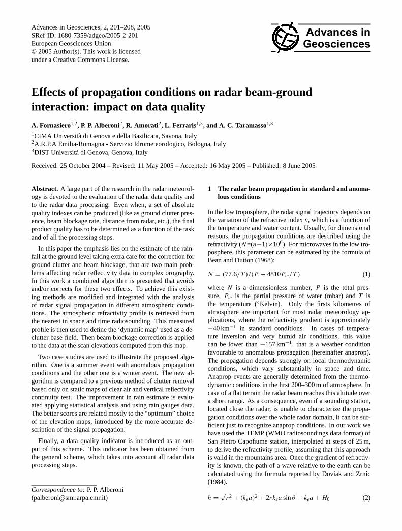
Figure 1. Beam path at 0.5° antenna elevation. It has been ’broken’ the principal lobe in small rays and followed the path of
each one.
Figure 2. N gradient profile. Time: 01/08/2003 00:00.
Figure 3. Comparison between beam blockage attenuation calculated assuming rectangular beam (dashed line) and gaussian beam (solid line). The beam center offset is related to the half-width of a 13° 3-dB beam (figure reported from Bech et al., 2003). The difference between the two assumptions is small taking into consideration a maximum attenuation rate of 50%, i.e. a beam center offset ranging from 0 to 1.
Fig. 1. Beam path at 0.5◦ antenna elevation. It has been “broken”the principal lobe in small rays and followed the path of each one.
standard profile is used. Into the dynamic map are stored thehighest elevations between those indicated by the three maps.
2.2 Removal of residual anomalous propagation clutter
Because of the approximations in the path modelling, such asthe spatial homogeny of refractivity profiles and their lineartime dependence, it is necessary to remove residual anapropclutter. The method used in this work has been implementedby Alberoni et al. (2001) and is based on a vertical Z continu-ity test (hereinafter VCT). Anomalous propagation is iden-tified when the difference between Z value at the elevationof dynamic map and at the successive elevation exceeds thethreshold T1 shown in Table 1, or if this difference is greaterthan 0 dbZ and the reflectivity value at the successive eleva-tion is lower than T2. The main idea of this methodology isthat anaprop clutter, having a small vertical extension, shows,as own “signature”, a steep decrease in the produced reflec-tivity value, more rapid than in cases of rain. We have intro-duced a modification to this scheme that takes into accountcases of rain with limited vertical development. It consists inintroducing a condition to apply the test beyond 80 km fromradar: when the elevation is greater than the first, the differ-ence between the reflectivity at the previous and at the chosenelevation must exceed 10 dbZ. In this way, the bin is markedas possibly contaminated by anaprop clutter, and only in thiscase, if the VCT test is positive, it is rejected.
2.3 Beam blocking model
The beam blocking model developed from Bech et al. (2003)is based on a geometric-optic approach. Because for typicalradar frequencies the physical dimensions of ground targetsare much larger than the wavelength, case of scattering ofradiowaves from ground can be considered in the geomet-ric optics approximation. This model assumes that, the radarbeam has a circular cross-section, where the power densityis uniform. Bech et al. (2003) have shown that the differ-ence in terms of beam blockage rate between a Gaussianantenna gain pattern (more realistic in standard conditions)

A. Fornasiero et al.: Impact on data quality 203
f(θerr) 1- θerr f(∆trs) exp(-∆trs/∆T) f(∆rrs) exp(-∆rrs/∆R)
Figure 1. Beam path at 0.5° antenna elevation. It has been ’broken’ the principal lobe in small rays and followed the path of
each one.
Figure 2. N gradient profile. Time: 01/08/2003 00:00.
Figure 3. Comparison between beam blockage attenuation calculated assuming rectangular beam (dashed line) and gaussian beam (solid line). The beam center offset is related to the half-width of a 13° 3-dB beam (figure reported from Bech et al., 2003). The difference between the two assumptions is small taking into consideration a maximum attenuation rate of 50%, i.e. a beam center offset ranging from 0 to 1.
Fig. 2. N gradient profile. Time: 01/08/2003 00:00.
and a uniform circular one is small into the considered beamblockage limits, i.e. 0–50% (see Fig. 3).
This simplification is useful in nearly all standard propa-gation conditions. The example in the Fig. 1 shows that thepath of the principal lobe “broken” in small rays, at the el-evation of 0.5 degree: the lower part bents to the soil andthe upper part propagates freely in the atmosphere. We canalso conclude that at the elevation of 0.5 degrees, neither thepower density could be considered constant, nor the form ofthe section is circular. However, at the higher elevation an-gles this approximation is reliable for the application of beamblockage rate evaluation. Therefore, in this case, the fractionof power lost is equal to the fraction of beam cross-sectionblocked by ground.
2.4 The quality evaluation: a necessary conclusion of dataprocessing
The ground clutter suppression methodology and beamblockage correction can be subdivided into three steps:
1. selection of a dynamic clear air map
2. correction for the power loss
3. removal of anaprop residual clutter using modified VCTmethod
At the end of this sequence, the quality evaluation synthe-sizes the information available about the initial datum condi-tion and the processing efficacy.
In a detailed analysis, we can define three levels of qualityevaluation each corresponding to an intermediate product:
– the hardware level, where the output quantity is a power
– the measurement level, where the output is reflectivity
– the final product level where the output is the rain rate.
In this work, the input data to our processing scheme is thepolar volume. Prior to our processing Doppler clutter sup-pression was applied to radar signal. Neglecting what hap-pens at the hardware level, we have determined the qualityfunction at the second level.
f(θerr) 1- θerr f(∆trs) exp(-∆trs/∆T) f(∆rrs) exp(-∆rrs/∆R)
Figure 1. Beam path at 0.5° antenna elevation. It has been ’broken’ the principal lobe in small rays and followed the path of
each one.
Figure 2. N gradient profile. Time: 01/08/2003 00:00.
Figure 3. Comparison between beam blockage attenuation calculated assuming rectangular beam (dashed line) and gaussian beam (solid line). The beam center offset is related to the half-width of a 13° 3-dB beam (figure reported from Bech et al., 2003). The difference between the two assumptions is small taking into consideration a maximum attenuation rate of 50%, i.e. a beam center offset ranging from 0 to 1.
Fig. 3. Comparison between beam blockage attenuation calculatedassuming rectangular beam (dashed line) and gaussian beam (solidline). The beam center offset is related to the half-width of a 1.3◦
3-dB beam (figure reported from Bech et al., 2003). The differencebetween the two assumptions is small taking into consideration amaximum attenuation rate of 50%, i.e. a beam center offset rangingfrom 0 to 1 (courtesy: AMS).
Assuming that the data quality is determined byn inde-pendent factors, that are defined by different steps of radardata processing, we have defined the final quality indicatoras a product ofn componentsQi (i=1,..n).
Q =
n∏1
Q∗
i (3)
Each component is calculated combining the quality indica-tors of the data before the correction (Qdi), and after them(Qci), taking into account their maximsQdmax, Qcmax
Q∗
i = Q∗
max,i −(Qdmax,i − Qdi
) (Qcmax,i − Qci
)(4)
Assuming the quality values ranging from 0 to 1 the newfunction is:
Q∗
i = 1 − (1 − Qdi) (1 − Qci) (5)
This type of function complies with the following conditions:
a) quality indicator after a correction is higher or at leastequal to the one before the correction, because negativevalues ofQcare rejected;
b) quality indicator after the perfect correction is equal tothe one of a perfect data.
The choice of a product function is due to the necessity,to satisfy simultaneously each minimum quality condition tohave a reliable data. Furthermore, it is a very general def-inition that requires the detailed knowledge of the task andof the process to obtain the product. The methodology pre-viously described is a part of the complete chain of data

204 A. Fornasiero et al.: Impact on data quality
Table 2. Quality components.Qd andQcare the quality of the datum and of the correction respectively.BBandBBmax indicates the actualand the maximum accepted beam blocking rate.β is the regression exponent of radar-gauges assessment factor,θerr is the antenna pointingerror,1T and1R are the time scale and the distance scale,1trs and1rrs are the time and space distance from the nearest radiosounding,r is distance from radar.
Factors affecting quality Qd Qc
Beam blocking 1-BB/BBmax f(BB)*f( θerr)*f( 1trs )*f( 1rrs )Clutter 0 if clutter is present; 1 elsewhere 0.5Vertical continuity test 0.8 if upper elevation is not present; 1 elsewhere 0Radar distance Qd= exp(−βr) 0f (θerr) 1−θerr
f (1trs) exp(−1trs/1T )
f (1rrs) exp(−1rrs/1R)
processing that can include attenuation correction, verticalprofile of reflectivity reconstruction, secondary trip echo re-moval, event classification etc. Each one of these steps pro-duces quality output potentially to be included in the productquality indicator. In this work only a part of this problem isconsidered, namely only the quality components that are re-lated to the problems considered in the presented methodol-ogy: clutter, beam blocking, radar distance, vertical continu-ity test are considered. These functions are given in Table 2.
In case of the beam blocking, the data quality before thecorrection is defined as linear dependent on the beam block-age rate, with a maximum limit of 50%. Above this limit thedata is rejected. The quality of the correction is determinedas a product of a factor decreasing with beam blocking rate,and depends on the time and space distance from the nearestradiosounding (1trs and1rrs) and on the antenna pointingerror, θerr. For the radiosounding distance we have con-sidered exponential degradation with a time scale1T of 4 hand a distance scale1R of 50 km (this values are derivedfrom meteorological data assimilation common procedures).The last factor depends linearly on the antenna pointing er-ror θerr: the function is derived from the work of Bech etal. (2003), that shows that an errors of 0.05◦ and 0.1◦ pro-duce an error of 5% and 10% respectively in the beam block-age evaluation.
In case of clutter suppression, the quality before the cor-rection is assumed constant and equal to 0 if clutter is de-tected and 1 elsewhere. The quality of the correction is as-sumed equal to 0.5.
In case of vertical continuity test presence, the quality ofthe datum is assumed equal to 0.8 if the test is not applied(i.e. it falls the upper elevation datum), and 1 elsewhere.
Finally it has been chosen a quality component decreasingexponentially with the radar distance (see Table 2) his def-inition is derived from the work of Koistinen and Puhakka(1981) where the climatological assessment factor (ratio be-tween rain gauges rain and radar rain) is shown to have anexponential degradation vs. distance. The regression coef-ficient β is calculated using one year of data and used inthe quality component function. This value partially includes
the climatological effect of the vertical profile of reflectivity(VPR), because it is related to the increase of the height. Thechoice of the component functions is reasonable but requiresoptimization for operational applications.
3 Results
The described methodology has been applied and tested ontwo case studies related to different types of meteorologi-cal events. The first is a thunderstorm occurred in summer2003, on 31 July when anomalous propagation conditionshave been verified. The second is a case of stratiform rainoccurred in winter 2003, on 10 December in the afternoon.The reflectivity dataset is generated by San Pietro Capofi-ume radar located in Italy, in the Po Valley 30–40 km fromthe mountains of Appennino. A radiosounding station is co-located with the radar. We have used the radar scans at min00, 15, 30, 45, decluttered by Doppler filter and acquired atPRF of 1200 Hz and impulse time of 0.5µs, i.e. with a rangeresolution of 75 m, smoothed afterwards to 250 m. The an-tenna beamwidth is 0.9◦ and their scan elevations are 0.5◦,1.4◦, 2.3◦, 3.2◦, 4.1◦. The performance of the new algo-rithm has been evaluated, at first qualitatively, comparing itwith a method of reflectivity correction based only on CAMand VCT. Thereafter a statistical analysis on the two com-plete events has been performed to evaluate quantitatively itsreliability. To illustrate the operational sequence includingthe quality output we have chosen an instant of the thunder-storm event with anomalous propagation. In Fig. 2 the re-fractivity gradient obtained from the nearest radiosoundingis presented. A deep temperature inversion caused anapropin the first 200 m, in fact the value of dN/dh is smaller than−157 km−1. The form of the radar beam for the elevationof 0.5◦ is illustrated in Fig. 1 and has been previously dis-cussed. Using this atmospheric description we have definedthe FCEM and the BBEM and combining them with theCAM we have obtained the dynamic map (Fig. 4). In thiscase, because of the strong anomalous propagation, the ele-vation is nearly overall greater than the first. At this elevationthe modelled beam blockage is almost absent.

A. Fornasiero et al.: Impact on data quality 205
Figure 4. High panel: BBEM + FCEM (lefts) and static map of clear air CAM (rights). Low panel: final dynamic map. Time: 31/07/2003 20:00.
Figure 5. Anomalous propagation (green), detected from original scheme of Alberoni (left panel) and from new scheme (right panel). Time: 31/07/2003 20:00.
Fig. 4. High panel: BBEM+FCEM (lefts) and static map of clear air CAM (rights). Low panel: final dynamic map. Time: 31/07/2003 20:00.
Figure 4. High panel: BBEM + FCEM (lefts) and static map of clear air CAM (rights). Low panel: final dynamic map. Time: 31/07/2003 20:00.
Figure 5. Anomalous propagation (green), detected from original scheme of Alberoni (left panel) and from new scheme (right panel). Time: 31/07/2003 20:00.
Fig. 5. Anomalous propagation (green), detected from original scheme of Alberoni (left panel) and from new scheme (right panel). Time:31/07/2003 20:00.
Next step is the removal of anomalous propagation clut-ter. In Fig. 5 the maps of anaprop obtained from original andmodified scheme are presented: at the SO bound of the map aprecipitation echo is recognised from the original algorithmas anomalous propagation; the second scheme avoids this er-ror.
Thereafter the set of quality indexes (i.e. the fractionalbeam blocking, and the anomalous propagation clutter detec-tion) has been calculated and used for the evaluation of the“final” quality, following the method described in Sect. 2.4
and in Table 2. In Fig. 6, the map of data quality calculatedcell per cell is represented, for the two compared methodsand in a Cartesian grid of 1 km×1 km of resolution. It is vis-ible the high quality difference behind the mountains (zonebetween 180◦ and 270◦ azimuth, affected by beam blockage)and in the anaprop area. Further in the first 20–25 km the ef-fect of side-lobe clutter contamination is clearly visible. In-side this area, data are not corrected by the methods; indeedin this zone it is used the higher elevation available, since thatalso this one is still affected by some clutter residual and so

206 A. Fornasiero et al.: Impact on data quality
Figure 6. Quality maps, in cartesin grid, related to the CAM+VCT method (left panel) and to the new method of radar data correction (right panel). Time: 31/07/2003 20:00.
Figure 7. Map of cumulated rain after CAM+VCT method (left panel) and after the new method correction (right panel). Event 10/12/2003 from 15:00 to 23:00. Increasing rain from blue to red.
Fig. 6. Quality maps, in cartesin grid, related to the CAM+VCT method (left panel) and to the new method of radar data correction (rightpanel). Time: 31/07/2003 20:00.
it is not possible to apply the vertical continuity test. As aresult the quality is lower than elsewhere. Furthermore, theaverage quality value increases (using the new methodology)from 0.49 to 0.55.
Once we have illustrated all the processing steps, let us fo-cus the attention on the events. The cumulated rain for thestratiform event has been calculated, using a medium Mar-shall and Palmer relation. Figure 7 shows the reflectivitymap at 1 km resolution obtained from the method of clut-ter removal based on CAM and VCT, and that obtained fromthe new combined method. It is clear that the new schemereduces the ground clutter and the beam blockage effect (be-yond the mountains the signal is more continuous). It is alsovisible that the remaining problem of the vertical variation ofreflectivity has a strong affect on the final result.
To highlight the impacts of the new algorithm inside andbeyond the mountains area, a quantitative-statistical analysishas been performed using hourly rain measured during theevent from about 130 raingauges located from 135◦ to 270◦
azimuth and more than 20 km far from radar, to avoid thearea of secondary lobes. The radar rain has been interpolatedin a grid of 1 km×1 km of resolution and cumulated in thehour; the hourly datum of each raingauge has been comparedwith them of the radar in the correspondent cell. To convertZ in rain (R), we have used an equation of type Marshalland Palmer (1948),Z=aRb. In absence of the optimum pairof coefficientsa andb it has been fixeda=250 andb=1.5for stratiform rain anda=500 andb=1.5 for convective rainas indicated by Joss and Waldvogel (1970). CallingRG thehourly cumulated rain rate measured by the gauges andRR
them measured by the radar over the correspondent cells, thebias〈εR〉 is defined as
〈εR〉 = 〈RR − RG〉 (6)
where the angle brackets means the average over time andover the cells. The other calculated indexes are (Marzano et
al., 2004):
– the root mean square error
RMSE =
√⟨ε2R
⟩(7)
– the fractional mean reduction
FMR =〈RG〉 − 〈εR〉
〈RG〉(8)
– the fractional variance reduction
FV R =
⟨σ 2
RP
⟩−
⟨σ 2
εE
⟩⟨σ 2
RP
⟩ (9)
The optimal value of FMR, FVR is 1 and of RMSEis 0. We have calculated this indexes using radar rainrates obtained from the new algorithm (BDA) and from“CAM+VCT” algorithm (SA) and we have compared them.Figures 8 and 9 shows RMSE and the FMR, for the two meth-ods, calculated respectively in the summer and in the wintercase study.
The new algorithm shows a lower RMSE in both cases. Itis difficult to evaluate the performance of the algorithms ob-serving the bias and similar indexes as FMR. This indexes arestrictly influenced by factors such as the correct calibrationof a andb coefficients and the VPR correction. In fact, theintroduction of propagation and BB model increases oftenthe height at which the reflectivity data are kept, with respectto the old algorithm; this can imply for the final rain rate asmoothing of the previous improvement or even a worsening.
FVR, in the analysed cases, is very near to 1 because thevariance of the error is smaller than the variance of the rainfield. Further, it must be noted that the indexes are calcu-lated on cells that are concentrated in the Appennino areainto the region Emilia Romagna; i.e. the performance of thealgorithm in the boundary of the radar map is also neglected.

A. Fornasiero et al.: Impact on data quality 207
Figure 6. Quality maps, in cartesin grid, related to the CAM+VCT method (left panel) and to the new method of radar data correction (right panel). Time: 31/07/2003 20:00.
Figure 7. Map of cumulated rain after CAM+VCT method (left panel) and after the new method correction (right panel). Event 10/12/2003 from 15:00 to 23:00. Increasing rain from blue to red. Fig. 7. Map of cumulated rain after CAM+VCT method (left panel) and after the new method correction (right panel). Event 10/12/2003
from 15:00 to 23:00. Increasing rain from blue to red.
Figure 8. RMSE and FMR of summer event for the CAM+VCT algorithm (SA=static map +anaprop removal) and for the new algorithm (BDA=blocking + dynamic map + anaprop removal). MP coefficients are a=500 , b=1.5.
Figure 9 RMSE and FMR of winter event for the CAM+VCT algorithm (SA=static map +anaprop removal) and for the new algorithm (BDA=blocking + dynamic map + anaprop removal). MP coefficients are a=250, b=1.5.
Fig. 8. RMSE and FMR of summer event for the CAM+VCT algo-rithm (SA=static map +anaprop removal) and for the new algorithm(BDA=blocking + dynamic map + anaprop removal). MP coeffi-cients area=500 ,b=1.5.
4 Conclusions
The base-idea of the illustrated methodology is to privilegeerrors minimization respect to their correction. Anapropsuppression can, in fact, lead to underestimation and beamblocking correction, without adequate knowledge of the at-mospheric conditions, can produce wrong results. The pre-sented approach shows some advantages with respect to theCAM+VCT algorithm. Firstly, it takes into account the real(or approximated) atmospheric state and recognizes anoma-lous propagation conditions. This permits to change the ele-vations at which the data are kept, avoiding or reducing thisartefact, before the application of the anaprop removal al-gorithm. Second, it introduces the beam blockage correctionand produces a more reliable field after the mountains, reduc-
Figure 8. RMSE and FMR of summer event for the CAM+VCT algorithm (SA=static map +anaprop removal) and for the new algorithm (BDA=blocking + dynamic map + anaprop removal). MP coefficients are a=500 , b=1.5.
Figure 9 RMSE and FMR of winter event for the CAM+VCT algorithm (SA=static map +anaprop removal) and for the new algorithm (BDA=blocking + dynamic map + anaprop removal). MP coefficients are a=250, b=1.5.
Fig. 9. RMSE and FMR of winter event for the CAM+VCT al-gorithm (SA=static map + anaprop removal) and for the new al-gorithm (BDA=blocking + dynamic map + anaprop removal). MPcoefficients area=250,b=1.5.
ing the shadowing effect of mountains and valleys. Further,the algorithm is simple to implement and has a low computa-tional cost. The schema is suitable to an operational use butit must be integrated with the correction of the vertical profileof reflectivity and with the event classification to choose theZ-R relation. Moreover additional effort should be devotedto verify the efficacy of each processing step and to develop amethod to retrieve the approximated propagation conditionsin real time.
The other relevant aspect is that, the schema produces in-dicators of data quality that are useful to evaluate its relia-bility in hydrological and meteorological applications suchas data assimilation. The final quality value takes memoryof every correction and processing step and corresponds tothe spatial distribution of its effects magnitude. It is closely

208 A. Fornasiero et al.: Impact on data quality
dependent on the problem (i.e. on the product) and on theoperation chain to obtain the product. It is meant as tool toevaluate the reliability of radar data for application such asdata assimilation, radar composite etc. and can be considereduseful to evaluate and compare performances of different al-gorithms or processing lines, alternatively to the use of raingauges. However, the quality indicator here presented is onlypartial. It is necessary to add quality components related tothe correction steps here not yet developed (VPR, attenua-tion, event classification) to obtain a complete description ofthe data quality. The highest interest is in fact devoted to theevaluation of the quality of the final product. Furthermore,it is necessary to optimise the definition of the quality func-tions testing them on operational applications and historicaldataset.
Acknowledgements.The authors greatly acknowledge J. Bech(MeteoCAT) for the ray propagation and beam blocking code. Thiswork is partially supported by CARPE DIEM, a research projectsupported by the European Commission under the 5th FP (ContractNo. EVG1-CT-2001-0045), and form the GNDCI through theproject RAM. The comments and suggestion of the two anonymousreferees have been greatly appreciated.
Edited by: G. BoniReviewed by: anonymous referees
References
Alberoni, P. P., Anderson, T., Mezzasalma, P., Michelson, D. B., andNanni, S.: Use of the vertical reflectivity profile for identificationof anomalous propagation, Meteorological Applications, 8, 257–266, 2001.
Bean, B. R. and Dutton, E. J.: Radio Meteorology, Dover Publica-tions, 435 pp., 1968.
Bech, J., Codina, B., Lorente, J., and Bebbington, D.: The sensitiv-ity of single polarization weather radar beam blockage correctionto variability in the vertical refractivity gradient, Journal of At-mospheric and Oceanic Technology, 20, 6, 845–855, 2003,
Doviak, R. J. and Zrnic, D. S.: Doppler radar and weather observa-tions, Academic Press, 562 pp., 1993.
Joss, J. and Waldvogel, A.: A method to improve the accuracyof radar-measured amounts of precipitation, Prepr. 14th Conf.Radar Meteorol., pp. 237–238, 2001.
Koistinen, J. and Pohjola H.: Operational vertical reflectivity profilecorrection in radar network composites in Finland, Preprints, 2ndEuropean Radar Conference, ERAD, 2002.
Marzano, F. S., Picciotti, E., and Vulpiani, G.: Rain Field andReflectivity Vertical Profile Reconstruction From C-Band RadarVolumetric Data, Ieee transactions on geoscience and remotesensing, 42, 5, 2004.
Marshall, J. S and Palmer, W. McK.: The distribution of raindropswith size, J. Meteor., 5, 165–166, 1948.
WMO Publications: Catalogue of Meteorological Bulletins –Weather reporting, No. 9, Vol. C1,http://www.wmo.int/web/ddbs/Jen/VolumeC1/VolC1.html, 2004.