charge on innovation challenge
TRANSCRIPT

CHARGE ONINNOVATION CHALLENGEELECTRIFYING MINESVendor Technical InformationMAY 2021

This presentation contains forward looking statements of Vale S.A., Rio Tinto, and BHP Group Operations – collectively referred to as “Patrons”, which may include statements regarding plans, strategies and objectives of management, future performance and future opportunities relating to achieving zero greenhouse gas emissions for haul trucks. This information is disclosed on condition that it will only be used for the purpose outlined in this presentation. The forward looking statements in this presentation are not guarantees or predictions of future performance, and involve known and unknown risks, uncertainties and other factors, many of which are beyond our control, and which may cause actual results to differ materially from those expressed in the statements contained in this presentation.
Each of the Patrons has various risk factors, as disclosed in their Annual Reports, that may cause actual results to differ from the forward-looking statements in this presentation.
No Patron undertakes any obligation to update or review any forward-looking statements.
DISCLAIMER
Forward-looking statements
No offer of securities Nothing in this presentation should be construed as either an offer to sell or a solicitation of an offer to buy or sell any securities of any Patron in any jurisdiction, or be treated or relied upon as a recommendation oradvice by a Patron.
2 | Charge On Innovation Challenge

EXECUTIVE SUMMARY
CHARGE ONINNOVATION CHALLENGE

INTRODUCTION
BHP, RioTinto and Vale are the founding partners of an exciting new collaboration - The Charge On innovation challenge.
To develop innovative ways to safely charge our mining truck fleets without losing productivity
But we cannot solve the decarbonization challenge alone.
And we are looking beyond mining for help.
The Charge On innovation challenge will be a vital step in achieving zero emissions mining.
We encourage other mining companies to join us in this challenge, take another step toward zero emissions mining, and to create operations we are proud to pass to the next generation.
4 | Charge On Innovation Challenge

ELECTRIFICATION IS AN IMPORTANT STRATEGY
• This has the potential to reduce the size of the battery required on the truck – Maximise payload• Reduces the number of trucks in the fleet because the trucks don’t have to stop to recharge – Optimise truck numbers• Potential for trucks to travel faster by providing charging and propulsion simultaneously – Maximise productivity
A key opportunity is to charge trucks in-cycle (i.e. while being loaded, dumping or hauling)
• It is important not to sacrifice truck payload as this is a large driver of productivity
Current battery technology constrains how much energy can be carried on board a truck
• This includes electrifying large trucks (220 tonne – 360 tonne payload)
A priority stream of work is to understand how to electrify our current way of operating
• Electrifying equipment• Exploring use of different size and types of equipment
Mining companies are exploring multiple ways of decarbonising material movement, including:
The scope of the Charge On Innovation Challenge is focussed on scalable, interoperablesolutions for delivering electricity to 220 tonne haul trucks, without adding time to the haul cycle.
5 | Charge On Innovation Challenge

CHARGE ON INNOVATION CHALLENGE PROCESS
In collaboration with
CHARGE ON INNOVATION CHALLENGE PROCESS
2021
‘CHARGE ON’COLLABORATION
WORKSHOP
Patrons Identifycharging solutions withbroad industry appeal
and application
EOI OPEN18 MAY
EOI CLOSE30 JUNE
PITCH
JUNE JULYMAY SEPTEMBER OCTOBERAUGUSTVENDORS
Create an attractiveopportunity for market Diversity of thought Patrons actively working
to decarbonize truck fleets
FINALSUBMISSION
FOUNDING PATRONS
Participation of Additional Patrons
ALL INDUSTRIES
CHALLENGE OUTPUTS
Opportunity to progress development in partnership with
OEMs, and other Miners
Potential to progress proposalsindividually or through collaboration
(e.g. multi-party development agreement)
6 | Charge On Innovation Challenge

SCOPEDEFINITION

CHARGE ON INNOVATION CHALLENGE
WHAT IS IT? The Charge On Innovation Challenge asks Vendors to present scalable, interoperable solutions that can safely deliver in the order of 400 kWh electricity to 220 tonne battery-electric trucks in a way that maintains or improves current productivity levels (without adding time to haul cycle).
WHY ARE WE DOING IT? WHAT HAPPENS IF WE DON’T DO IT? Current stationary charging systems would require substantial time to charge a truck out-of-cycle and current dynamic trolley systems are limited in where they can be deployed.
The Founding patrons - BHP, Rio Tinto and Vale - aim to engage the mining sector and adjacent sectors for solutions. We will do this with other miners to demonstrate that in-cycle charging for mining equipment is an attractive market worth pursuing.
WHEN? The Challenge will run from May to October with commercial discussions thereafter to tie into timelines in relation to a Battery Electric (BEV) truck being available for testing from as early as 2023.
We expect some solutions identified in the Challenge could provide propulsion to existing diesel-electric trucks. This may present a pathway to early implementation for dynamiccharging solutions.
There is no contractual obligation to procure any products or services at the end of challenge
?
?
?
8 | Charge On Innovation Challenge
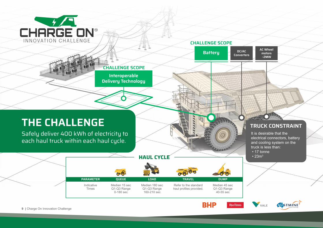
CHALLENGE SCOPE
InteroperableDelivery Technology
CHALLENGE SCOPE
BatteryAC Wheel
motors~2MW
DC/ACConverters
TRUCK CONSTRAINTTHE CHALLENGESafely deliver 400 kWh of electricity toeach haul truck within each haul cycle.
It is desirable that the electrical connectors, battery and cooling system on the truck is less than: • 17 tonne • 23m3
IndicativeTimes
Median 15 secQ1-Q3 Range
0-180 sec
PARAMETER �UEUE TRAVEL DUMPLOAD
Median 180 secQ1-Q3 Range160-210 sec
Refer to the standardhaul profiles provided.
Median 45 secQ1-Q3 Range
40-55 sec
HAUL CYCLE
9 | Charge On Innovation Challenge
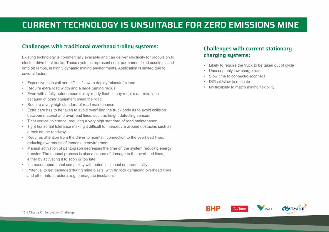
CURRENT TECHNOLOGY IS UNSUITABLE FOR ZERO EMISSIONS MINE
Challenges with traditional overhead trolley systems: Challenges with current stationary
charging systems:
Existing technology is commercially available and can deliver electricity for propulsion to electric-drive haul trucks. These systems represent semi-permanent fixed assets placed onto pit ramps, in highly dynamic mining environments. Application is limited due to several factors:
• Expensive to install and difficult/slow to deploy/relocate/extend• Require extra road width and a large turning radius• Even with a fully autonomous trolley-ready fleet, it may require an extra lane because of other equipment using the road• Require a very high standard of road maintenance• Extra care has to be taken to avoid overfilling the truck body as to avoid collision between material and overhead lines, such as height detecting sensors• Tight vertical tolerance, requiring a very high standard of road maintenance• Tight horizontal tolerance making it difficult to manoeuvre around obstacles such as a rock on the roadway• Requires attention from the driver to maintain connection to the overhead lines, reducing awareness of immediate environment• Manual activation of pantograph decreases the time on the system reducing energy transfer. The manual process is also a source of damage to the overhead lines, either by activating it to soon or too late• Increased operational complexity with potential impact on productivity• Potential to get damaged during mine blasts, with fly rock damaging overhead lines and other infrastructure, e.g. damage to insulators
• Likely to require the truck to be taken out of cycle• Unacceptably low charge rates• Slow time to connect/disconnect• Difficult/slow to relocate• No flexibility to match mining flexibility
10 | Charge On Innovation Challenge

CHALLENGE OPPORTUNITY STATEMENT
TO PROPOSE ELECTRICITY DELIVERY CONCEPTS:
1Vendor concept proposals will ideally be capable of providing a total of 400 kWh over the representative haul cycle, but this may be provided via multiple interactions with the haul truck over the haul cycle. Vendors may submit a solution that provides less than 400 kWh. Also, where possible, Austmine will provide assistance to match Vendors together, so that they may submit joint proposals that meet the 400 kWh target.
Designed with safety as the number one
priority, using inherent defensive design and
fail-safe principles
To supply a 220 tonne payload
battery-electric haul truck (scalable to
360 tonne ultra class)
Capable to transfer 400 kWh1 of electricity into each truck within
each haul cycle
To provide battery charging, or both
propulsion and battery charging
To be cost effective, minimize complexity,
and not reduce productivity
That promotes inter-operability
allowing different OEM trucks to utilize the
same electricitydelivery system
1 2 3 4 5 6
11 | Charge On Innovation Challenge

Broadly speaking, the “Charge On” Innovation Challenge’s Battery Limits are from the AC output terminals of a mine substation to aggregated DC output of the onboard battery system
1. Proposals may have different Technology Readiness Levels (TRL). All vendors to refer to TRL Framework supplied in Technical Information Pack2. Desirable that the concept can be trialled on a mine-site as early as 20233. Vendors may assume trucks have precision guidance via autonomous solutions4. Vendors to note if precision guidance is not required for concept5. Haul trucks available 7000 hours per annum6. Assume no constraining limitations on electricity supply7. Environmental conditions will vary due to global application8. Planned redundancy should be considered to ensure a reliable charging service9. Haul profiles will be provided in x, y, z format
In-Scope Out of Scope Other Considerations/Constraints
1. Electricity delivery between the mine electricity grid and the haul truck (i.e. assume AC mine power is reticulated adjacent to the load and haul network)2. Haul truck onboard battery and battery management technology3. Haul truck onboard electrical hardware for charge receival4. Interaction with the truck whilst stationary or moving5. Battery charging (including AC/DC, DC/DC conversion whether onboard or off board) and direct propulsion6. Site energy management, dispatch optimisation software and integration of concept into mine grid (optional inclusion)
1. On-site electricity reticulation2. Electricity supply to mine site3. Loading and ancillary equipment4. Haul trucks less than 220 tonnes payload5. Haul truck components (apart from onboard battery and electrical connection to delivery infrastructure)6. Regeneration of power into the battery
IN / OUT OF SCOPE
10. Assume concept will be on a mine site with controlled access and therefore some hazards may be managed that would be unacceptable in a public space11. Trolley Assist systems available today operate in the 1000-3000 direct current voltage range
12 | Charge On Innovation Challenge

HAUL CYCLEINFORMATION
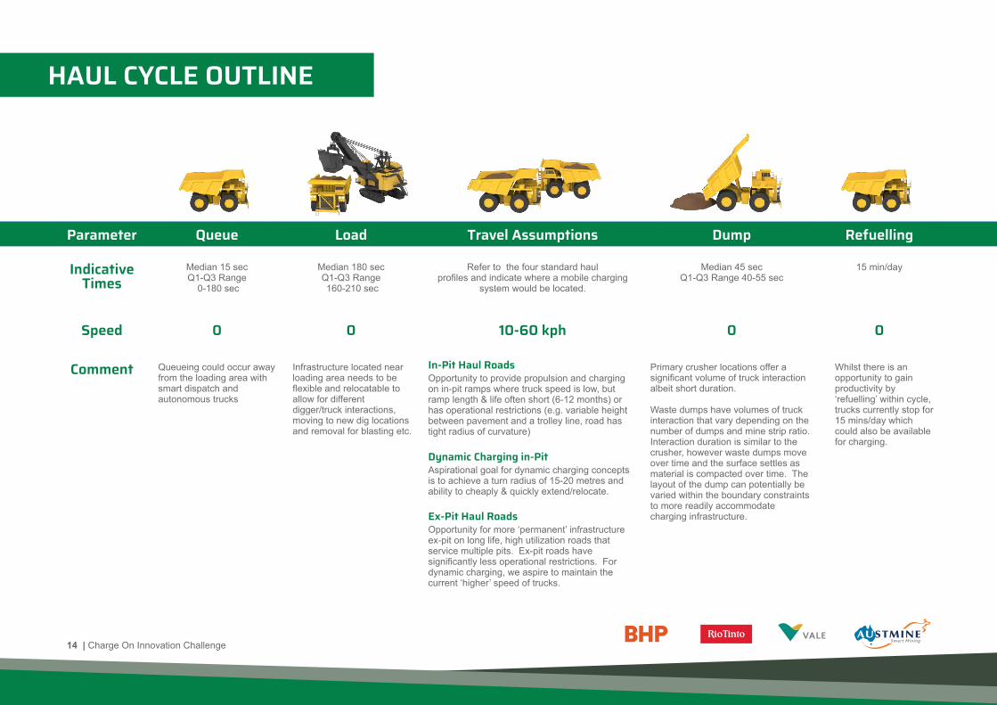
HAUL CYCLE OUTLINE
Parameter �ueue Load Travel Assumptions Dump Refuelling
Refer to the four standard haulprofiles and indicate where a mobile charging
system would be located.
Median 45 secQ1-Q3 Range 40-55 sec
15 min/day
Median 180 secQ1-Q3 Range 160-210 sec
Median 15 secQ1-Q3 Range
0-180 sec
10-60 kph
In-Pit Haul Roads
Dynamic Charging in-Pit
Ex-Pit Haul Roads
0
0
00
IndicativeTimes
Speed
Comment Queueing could occur away from the loading area with smart dispatch and autonomous trucks
Infrastructure located near loading area needs to be flexible and relocatable to allow for different digger/truck interactions, moving to new dig locations and removal for blasting etc.
Opportunity for more ‘permanent’ infrastructure ex-pit on long life, high utilization roads that service multiple pits. Ex-pit roads have significantly less operational restrictions. For dynamic charging, we aspire to maintain the current ‘higher’ speed of trucks.
Aspirational goal for dynamic charging concepts is to achieve a turn radius of 15-20 metres and ability to cheaply & quickly extend/relocate.
Opportunity to provide propulsion and charging on in-pit ramps where truck speed is low, but ramp length & life often short (6-12 months) or has operational restrictions (e.g. variable height between pavement and a trolley line, road has tight radius of curvature)
Primary crusher locations offer a significant volume of truck interaction albeit short duration.
Waste dumps have volumes of truck interaction that vary depending on the number of dumps and mine strip ratio. Interaction duration is similar to the crusher, however waste dumps move over time and the surface settles as material is compacted over time. The layout of the dump can potentially be varied within the boundary constraints to more readily accommodate charging infrastructure.
Whilst there is an opportunity to gain productivity by ‘refuelling’ within cycle, trucks currently stop for 15 mins/day which could also be available for charging.
14 | Charge On Innovation Challenge

THE HAUL CYCLE LANDSCAPE
ELECTRIC SHOVEL (trailing cable)
ELECTRIC SHOVEL (trailing cable)
�UEUEING & LOADING EX-PIT HAUL ROAD (high utilization)
IN-PIT TEMPORARY RAMP DUMP AT WASTE DUMP
DUMP AT CRUSHER
WASTE DUMP RAMP
MINE LOADING AREA
LOADING (backhoe configuration)
15 | Charge On Innovation Challenge

25002000 15001000 3000 3500 4000 4500 5000 55000
140160180200220240260280300
500
SEGMENT 1Solution needs to
be relocatable
SEGMENT 2Solution needs to be
relocatable/extendable
SEGMENT 3
needs to be relocatable/extendable
Waste dumpNon-Fixed destination
EXAMPLE HAUL PROFILES
760
740
720
700
680
660
640
0 2000 4000 6000 8000 10000
SEGMENT 3
SEGMENT 2
SEGMENT 1In-pit road
Restricted road widthSolution needs to be
relocatable/extendable
Ex-pit roadMulti use
Ex-pit road
Crusher
25002000 15001000 3000 3500 40000
400
510
550
610
660
710
500
SEGMENT 1In-pit roadRestricted road width Solution needs to be relocatable/extendable SEGMENT 2
Ex-pit
Crusher
PRO
FILE
APR
OFI
LE B
PRO
FILE
C
Proposals to demonstrate how/where 400 kWh can be supplied to each truckover one cycle for each of the following haul profiles
16 | Charge On Innovation Challenge

• Battery replaces diesel engine & fuel tank.• Battery, cooling system and electrical connection interface are desirable to weight less than 17 tonnes, and fit in a volume of 23 cubic meters.• Battery innovations may be proposed in the challenge.• Solutions should be focussed on servicing the 220 tonne payload truck size, but be scalable up to ultra class truck sizes (360 tonne).
29.5m Running Width
4%Cross Fall
4%Cross Fall
8.3m Truck Width 8m passing Width 2.4m 6m Window Width
1.8m Window Height
PitWallDown
PitWallUp
2.4m2.5m 8.3m Truck Width
38m Total Road Width
EXAMPLE 220 TONNE HAUL TRUCKS
7.32m 24’0’’ 3.83m 12’6’’
6.88m 22’7’’6.71m 22’0’’
7.26m 23’10’’
7.29m 23’11’’
6.88m 22’7’’
7.32m 24’0’’
6.88m 22’7’’
6.86m 22’6’’
FRONT VIEW
IN-PIT HAUL ROAD DIMENSIONS
REAR VIEW SIDE VIEW
17 | Charge On Innovation Challenge

PROFILE A
760
740
720
700
680
660
640
0 2000 4000 6000 8000 10000
SEGMENT 1
TONNAGE LIFE COMMENT
In-pit roadRestricted road widthSolution needs to berelocatable/extendable
SEGMENT 2Ex-pit roadMulti use
SEGMENT 3Ex-pit road
Crusher
SEGMENT 1
SEGMENT 2
SEGMENT 3
Ore and waste traveling up in-pit haul ramp. Restricted road width. Must allow for ancillary equipment to utilise road.
3 years
30 years
30 years
1.5 Mtpa
20 Mtpa
7 Mtpa
Ex-pit road ore and waste from multiple pits. Flexible road width.
Ex-pit road dedicated to haul ore to primary crusher. Flexible road width.
HAUL PROFILE CROSS-SECTION (ONE-WAY)
(Distance m)
TRUCK SPEED OVER HAUL PROFILE (LOADING POINT TO CRUSHER AND RETURN TO LOADING POINT)
Average Speed (km/h) Grade (%)
DUMP �UEUELOAD
(Distance m)
0
-10
0
10
20
30
40
50
60
2000 4000 6000 8000 10000 12000 14000 16000 18000 20000 22000
SEGMENT 1 SEGMENT 2 SEGMENT 3 SEGMENT 3 SEGMENT 2 SEGMENT 1
18 | Charge On Innovation Challenge

PROFILE A
1Duty Cycle - the percentage of maximum engine load
0
-20
0
20
40
60
80
100
2000 4000 6000 8000 10000 12000 14000 16000 18000 20000 22000
(Distance m)
SEGMENT 1 SEGMENT 2 SEGMENT 3 SEGMENT 3 SEGMENT 2 SEGMENT 1
DUMP �UEUELOAD
TRUCK DUTY CYCLE OVER HAUL PROFILE (LOADING POINT TO DUMP AND RETURN TO LOADING POINT)
Duty Cycle1 (%) Grade (%)
19 | Charge On Innovation Challenge

PROFILE B
TONNAGE LIFE COMMENT
SEGMENT 1
SEGMENT 2
Ore and waste traveling up in-pit haul ramp. Restricted road width. Must allow for ancillary equipment to utilise road.
11 years
11 years
16.5 Mtpa
8.8 Mtpa
(Distance m)
Ex-pit road dedicated to haul ore to primary crusher. Flexible road width.
Average Speed (km/h) Grade (%)0 500 1000 1500 2000 2500 3000 3500 4000
460
510
560
610
660
710
HAUL PROFILE CROSS-SECTION (ONE-WAY)
SEGMENT 1
In-pit roadRestricted road widthSolution needs to be
relocatable/extendable
SEGMENT 2
Ex-pit road
Crusher
0
-10
0
10
20
30
40
500 1000 1500 2000 2500 3000 3500 4000 4500 5000 5500 6000 6500 7000
TRUCK SPEED OVER HAUL PROFILE (LOADING POINT TO CRUSHER AND RETURN TO LOADING POINT)
SEGMENT 1 SEGMENT 2 SEGMENT 2 SEGMENT 1
DUMP �UEUELOAD
20 | Charge On Innovation Challenge

PROFILE B
0
-20
0
20
40
60
80
100
500 1000 1500 2000 2500 3000 3500 4000 4500 5000 5500 6000 6500 7000
TRUCK DUTY CYCLE OVER HAUL PROFILE (LOADING POINT TO DUMP AND RETURN TO LOADING POINT)
SEGMENT 1 SEGMENT 2 SEGMENT 2 SEGMENT 1
(Distance m)
DUMP �UEUELOAD
1Duty Cycle - the percentage of maximum engine load
Grade (%)Duty Cycle1 (%)
21 | Charge On Innovation Challenge

PROFILE C
0-500
-10
0
10
20
30
40
500 1000 1500 2000 2500 3000 3500 4000 4500 5000 5500 6000 6500 7000 7500 8000 8500 9000 9500
SEGMENT 1
LOAD �UEUEDUMP
SEGMENT 2 SEGMENT 3 SEGMENT 3 SEGMENT 2 SEGMENT 1
(Distance m)
R - Distance (m)
TRUCK SPEED OVER HAUL PROFILE (LOADING POINT TO DUMP AND RETURN TO LOADING POINT)
TONNAGE LIFE COMMENT
SEGMENT 1
SEGMENT 2
Used by one truck & shovel fleet for year. Very mobile location. Solution must be relocatable/extendable. Road width may be restricted. Must allow for ancillary equipment to utilise road.
1 years
3 years
16.5 Mtpa
32 Mtpa Bridge and main ramp used by two truck & shovel fleets. Bridge location/ elevation changes as mining progresses. Solution must be relocatable. Road width may be restricted. Must allow for ancillary equipment to utilise road.
SEGMENT 3 1 years16 Mtpa Ramp to dump site - used by 1 truck & shovel fleet. Very mobile location. Solution must be relocatable.
SEGMENT 1
Solutionneeds to berelocatable
SEGMENT 2
Solutionneeds to berelocatable/extendable
SEGMENT 3
Needs to berelocatable/extendable
Waste dumpNon-Fixed destination
0 500
140
160
180
200
220
240
260
280
300
1000 1500 2000 2500 3000 3500 4000 4500 5000 5500 6000
Average Speed (km/h) Grade (%)
HAUL PROFILE CROSS-SECTION (ONE-WAY)
22 | Charge On Innovation Challenge

PROFILE C
0-500
0
20
40
60
80
100
500 1000 1500 2000 2500 3000 3500 4000 4500 5000 5500 6000 6500 7000 7500 8000 8500 9000 9500(Distance m)
SEGMENT 1 SEGMENT 2 SEGMENT 3 SEGMENT 3 SEGMENT 2 SEGMENT 1
TRUCK DUTY CYCLE OVER HAUL PROFILE (LOADING POINT TO DUMP AND RETURN TO LOADING POINT)
DUMP �UEUELOAD
1Duty Cycle - the percentage of maximum engine load
Grade (%)Duty Cycle1 (%)
23 | Charge On Innovation Challenge

CHARGE ONINNOVATION CHALLENGESUPPLEMENTARY TECHNICAL INFORMATION

Basic principles observed and reported: Transition from scientific research to applied research.Essential characteristics and behaviors of systems and architectures. Descriptive tools are mathematicalformulations or algorithms.
Technology concept and/or application formulated: Applied research. Theory and scientific principles are focused on a specific application area to define the concept. Characteristics of the application are described. Analytical tools are developed for simulation or analysis of the application.
Analytical and experimental critical function and/or characteristic proof of concept: Proof of concept validation. Active research and development is initiated with analytical and laboratory studies. Demonstration of technical feasibility using breadboard or brassboard implementations that are exercised with representative data.
Component/subsystem validation in laboratory environment: Standalone prototyping implementationand test. Integration of technology elements. Experiments with full-scale problems or data sets.
System/subsystem/component validation in relevant environment: Thorough testing of prototyping in representative environment. Basic technology elements integrated with reasonably realistic supporting elements. Prototyping implementations conform to target environment and interfaces.
System/subsystem model or prototyping demonstration in a relevant end-to-end environment:Prototyping implementations on full-scale realistic problems. Partially integrated with existing systems. Limited documentation available. Engineering feasibility fully demonstrated in actual system application.
System prototyping demonstration in an operational environment: System prototyping demonstration in operational environment. System is at or near scale of the operational system with most functions available for demonstration and test. Well integrated with collateral and ancillary systems. Limited documentation available.
Actual system completed and qualified through test and demonstration in an operational environment: End of system development. Fully integrated with operational hardware and software systems. Most user documentation, training documentation, and maintenance documentation completed. All functionality tested in simulated and operational scenarios. Verification and Validation (V&V) completed.
Actual system proven through successful operations: Fully integrated with operational hardware/software systems. Actual system has been thoroughly demonstrated and tested in its operation al environment. All documentation completed. Successful operational experience. Sustaining engineering support in place.
1
2
4
3
5
6
7
8
9
Bankable Asset Class
TECHNOLOGY READINESS Level Summary
Market competition drivingwidespread development
Multiple CommercialApplication
System test,Launch &
System / Subsystem
TechnologyDemonstration
TechnologyDevelopment
System test,Launch &
Basic TechnologyResearch
Commercial Scale Up
Commercial Trial, small
HypotheticalCommercial Proposition
TRL2
1
2
3
4
5
6
7
8
9
CRI1
1
2
3
4
5
6
TRL FRAMEWORK
Reference documents: ARENA (https://arena.gov.au/)
• Technology Readiness Levels for Renewable Energy Sectors:
https://arena.gov.au/assets/2014/02/Technology-Readiness-Levels.pdf
• Commercial Readiness Index for Renewable Energy Sectors:
https://arena.gov.au/assets/2014/02/Commercial-Readiness-Index.pdf
1Commercial Readiness Index2Technology Readiness Level
25 | Charge On Innovation Challenge

ILLUSTRATIVE CHARGE ON CONCEPTS
Ideas to stimulate thinking Challenge is not restricted to these concepts
HIGH SPEED DYNAMIC CHARGING
�UICK CONNECT STATIONARY CHARGER �UICK CONNECT STATIONARY CHARGER
MOBILE AUTONOMOUS CHARGER WIRELESS DYNAMIC CHARGER
BATTERY SWAPPING
26 | Charge On Innovation Challenge

SUBMISSIONRE�UIREMENTS

INFORMATION WE ARE RE�UESTINGCATEGORY
Concept operability
Commercialisation
Value
TECHNICAL INFORMATION RE�UIRED AT INITIAL SUBMISSION
• Identification of key risks and how they are managed/mitigated
INFORMATION REQUESTED
• How many kWh can be supplied in a cycle for the supplied haul profiles (target 400kWh)• Breakdown of energy (kWh) and power (kW) transferred to truck, at each interaction point in the cycle• Can the solution simultaneously charge the battery and power the drive train?• Battery: charge rate, chemistry, total energy capacity (kWh), pack weight and volume, cost, round trip efficiency, and state of charge across the haul cycle
• Has this technology/concept been deployed in other sectors? i If yes, please provide the range of voltage level, current, and power. ii If yes, and if the solution applies to moving machinery, what are the current limits on speed, vibration?• Can the solution be deployed on open spaces, including high levels of dust, fog, heavy rainfall, on unpaved ground?• Are there any major restrictions on elevation and operating temperature?• Can the solution be operated manually, or is a high level of precision needed? For the latter, are there any modifications needed on the truck/cab?• What are the limits of “misalignment” (positioning tolerance) between power source and sink, both vertically and horizontally?• How long does it take to establish the physical connection between source and sink? And for the decoupling?• How long does it need between the physical connection and before charging begins?
• How the concept connects the truck and the mine grid to deliver electricity• Description of what needs to be located on the truck (weight, volume) and where on truck
Description of:• Vendor to list/describe technology and operations assumptions/constraints.• how it is deployed, extended, relocated (if relevant)• for dynamic charging solutions (minimum turning radius)
• Articulation of technology development plan showing timing of key milestones
Nothing at EOI
Nothing at EOI
HSE
CRITERIA
Energy delivery
Operationalcharacteristics
Interoperability
Integration &deployability
Technology readiness
Commercial readiness
Vendor capability
Vendor needs
Productivity
Life cycle
Capital intensity
Nothing at EOI
Nothing at EOI
• Identification of gaps to commercialize and plan for how gaps will be filled
• Articulate Vendor support requirements and preferred commercial model(s) to support commercialization plan (ie equity, commitment to purchase, grant, in-kind etc) including timing
28 | Charge On Innovation Challenge

INFORMATION WE ARE RE�UESTING AT FINAL SUBMISSION (1 of 2)CATEGORY
Concept operability
INFORMATION REQUESTEDCRITERIA DESCRIPTION
• Overall risk assessment • dentification of key risks and how they are managed/mitigated• Any restrictions relating to environment in which system operates (eg max/min ambient temperature, elevation, vibration, rainfall). Is there a range of extra design features that would be required for extra low/high ambient conditions• Any supplementary fire protection/Thermal runaway prevention information including but not limited to battery cell/module testing data and certifications (IEC62133, IEC 62660, IEC 61982, ISO 12405, UL Subject 2580, etc.)
Overall HSE rating and degree to which defensive design and fail-safe principles are incorporated into concept
Concept effectiveness of energy delivery (Breakdown of energy consumed by the truck, energy delivered directly to the drive train, and energy to battery across the haul cycle)
Concept ability to operate in physical environment
How well does the system scale to charge different truck sizes, and how easy would it be to configure to different truck OEMs
Ease of implementing the solution into an operating mine site (and ability to retrofit)- is there an impact to mine operations to deploy the solution- how complex is the solution
• How many kWh can be supplied in a cycle for the supplied haul profiles (target 400kWh)• Charging topology information (onboard/offboard) and whether bi directional Vehicle to grid (V2G) is contemplated (optional)• Breakdown of energy (kWh) and power (kW) transferred to truck, at each interaction point in the cycle• How many trucks can be charged simultaneously, max charge rates per vehicle and understanding of option to stagger charging on a fleet wide basis• Battery assumptions: charge rate, chemistry, total energy capacity (kWh), pack weight and volume, cost, round trip efficiency, and state of charge across the haul cycle• Can the solution simultaneously charge the battery and power the trucks drive train?• Breakdown of energy delivered direct to drivetrain or via battery (and the associated energy losses) for each haul cycle• Description of the expected impact on power quality resulting from operation of your technology - particularly in relation to power factor, harmonics, phase imbalance and electrical transients
• Has this technology/concept been deployed in other sectors? i If yes, please provide the range of voltage level, current, and power. ii If yes, and if the solution applies to moving machinery, what are the current limits on speed, vibration?• Can the solution be deployed on open spaces, including high levels of dust, fog, heavy rainfall, on unpaved ground?• Are there any major restrictions on altitude and operating temperature?• Can the solution be operated manually, or is a high level of precision needed? For the latter, are there any modifications needed on the truck/cab?• What are the limits of “misalignment” (positioning tolerance) between power source and sink, both vertically and horizontally?• How long does it take to establish the physical connection between source and sink? And for the decoupling?• How long does it need between the physical connection and before charging begins?• Information on whether Vendor has any experience with Energy Management Systems and if so provide details
• How the solution physically and electrically connects to the truck (assume a high voltage connection point is available on the mine site to supply power)• Is there range of AC supply voltages that the product could be adapted to receive for different installations ( i.e standardize voltage to what voltage exists on sites already)• How is it scaled from 220t to 360t payload truck?• What are your requirements of truck Original Equipment Manufacturers (OEMs) to ensure interoperability• Does the battery OEM have any Inverter compatibility requirements (regarding OEMs or technical parameters)• Can the battery OEM provide experience of BMS compliance with specific inverter OEMs• Description of what needs to be located on the truck (weight, volume) and where on truck
Description of:• Vendor to list/describe technology and operations assumptions/constraints.• How it is deployed, relocated, extended (if relevant)• Dynamic Charging solutions (minimum turning radius, required road width, and maximum number of trucks per segment)• How does production continue when system is undergoing maintenance• If relevant, how the solution allows for mining equipment to utilise the same road as your solution (relocating diggers, dozers, water carts etc)
HSE
CRITERIA
Energy delivery
Operationalcharacteristics
Interoperability
Integration &deployability
29 | Charge On Innovation Challenge

https://arena.gov.au/assets/2014/02/Commercial-Readiness-Index.pdf
INFORMATION WE ARE RE�UESTING AT FINAL SUBMISSION (2 of 2)CATEGORY
Commercialisation
Value
INFORMATION REQUESTEDCRITERIA DESCRIPTION
• Table showing the Technology Readiness Level rating for each subsystem & articulation of technology development plan showing timing of key milestones• When will the system be ready for trialling on a mine site?• Are there any limitations on where the trial could be conducted (above and beyond limitations on eg max/min ambient temperature, elevation, vibration, rainfall)
• Commercialization plan showing timing of key milestones and assessment of Commercial Readiness Index• Projected pathway for cost decline as a function of production volume/economies of scale/automation (either entire vehicle or individual components)
• For mobile charging concepts, describe if/how it can be applied to provide propulsion to a diesel-electric truck
• Clear mapping of development plan requirements against organisation capability,• Identification of gaps to commercialize and plan for how gaps will be filled,• Company track record on new product development,• Experience in delivering product and services to industrial environment
• Articulate Vendor support requirements and preferred commercial model(s) to support commercialization plan (ie equity, commitment to purchase, grant, in-kind etc) including timing• Any limitations on Vendor support availability (considering global application)
• Change to cycle time• Expected system availability, reliability• Information regarding redundancy levels for on board components or number of fleet and charging stations• Impact on payload (What part of the contact solution has to be carried by the truck and what is its Volume, Weight)
• Expected life of key equipment and life cycle assessment including O&M and replacement costs (Project life span and component design life, Capacity degradation, Round trip efficiency, Operating and maintenance costs including capital replacements where applicable)
• Capital cost requirements to supply each of the three haul profiles (Profiles A, B and C)• Opportunities for optimisation including future projections with economies of scale and material availability
Maturity of concept/technology (TRL)Can the system be trialled on-site by 2023?
Rating of Commercial Readiness (CRI)Time to market
Opportunity to implement technology on existing diesel-electric truck fleets
Organisation capability and ability to commercialize
Vendor support requirement
Potential impacts on annual production
Expected life of key equipment and life cycle assessment
What is the relative capital cost intensity between different proposals
Technology readiness
CRITERIA
Commercial readiness
Early implementation
Vendor capability
Vendor needs
Productivity
Life cycle
Capital intensity
30 | Charge On Innovation Challenge

www.chargeoninnovation.com