check list – basic engineering package (2)
DESCRIPTION
Check List – Basic Engineering PackageTRANSCRIPT
Check List – Basic Engineering Package (BEP) Information Input/ Review
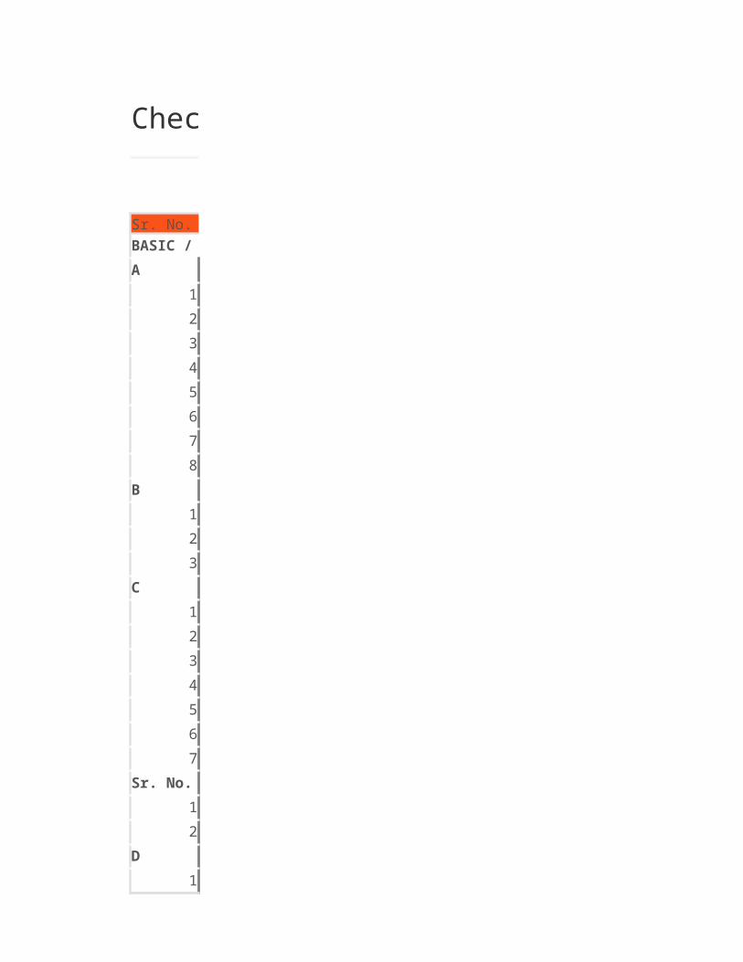
Sr. No.
A1
2
3
4
5
6
7
8
B1
2
3
C1
2
3
4
5
6
7
Sr. No.1
2
D1
2
3
4
BASIC / EXTENDED BASIC ENGINEERING PACKAGE CONTENT LIST (FROM PIPING REQUIREMENT)

5
6
7
8
9
10
REVIEW REQUIREMENTS OF BASIC ENGINEERING PACKAGEA
1
2
3
4
5
6
7
8
9
10
11
12
13
14
B1
2
3
4
5
6
CDEFGSr. No.F
1
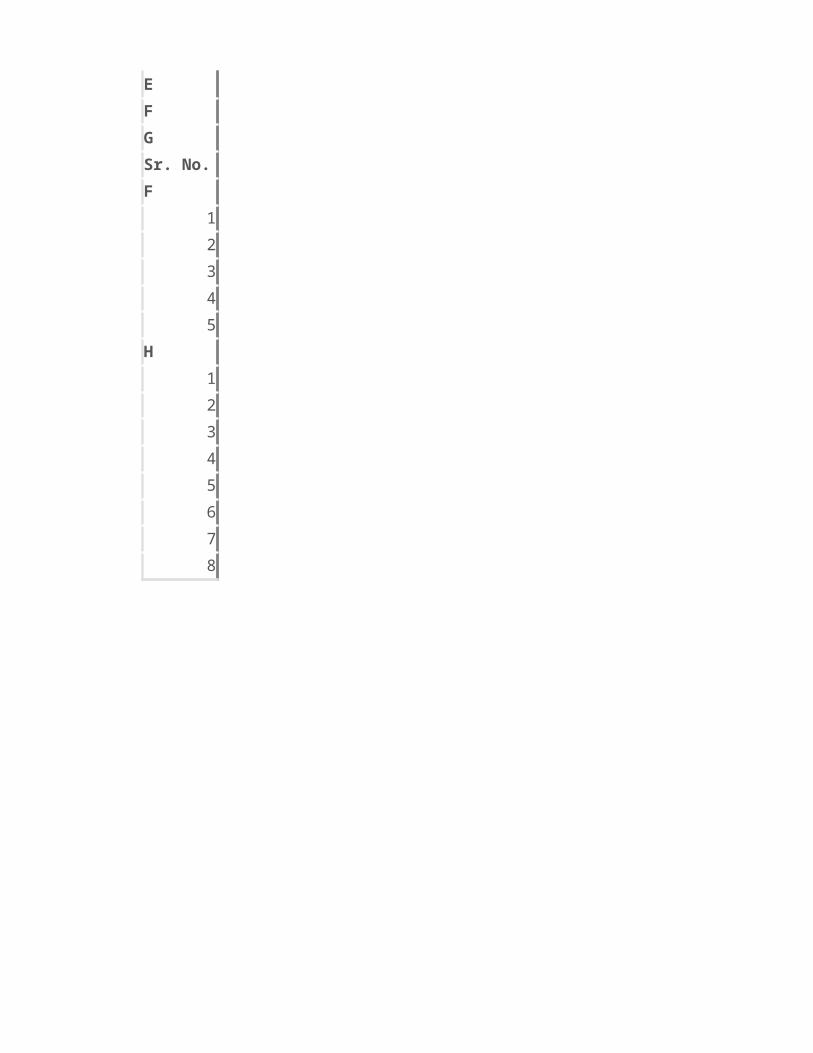
2
3
4
5
H1
2
3
4
5
6
7
8

Check List – Basic Engineering Package (BEP) Information Input/ Review
List
PROCESS INFORMATIONProcess Description
Process and Utility Flow Diagram
Process and Utility P & I Diagram
Utility Distribution Diagram
Minimum Equipment elevation summary or same information in different form
Equipment Process Datasheet
Hazardous Area Classification drawing
MECHANICALEquipment Engineering Datasheet
Package equipment vendor scope of work and tie in list
PIPING DESIGN
Preliminary Equipment Layout
Preliminary piping material specification or material selection criteria
Line List with process conditions
Special design requirements if any
Piping Design Philosophy
Instrument Process Hook up requirement
List
GENERALProject Description
Project Design Basis
Site Condition
List of Design codes and standards
BASIC / EXTENDED BASIC ENGINEERING PACKAGE CONTENT LIST (FROM PIPING REQUIREMENT)
Process Critical line List
Acceptable equipment external nozzle load
Preliminary plot plan
Stress analysis/ Support design guidelines/ standards
3D design criteria
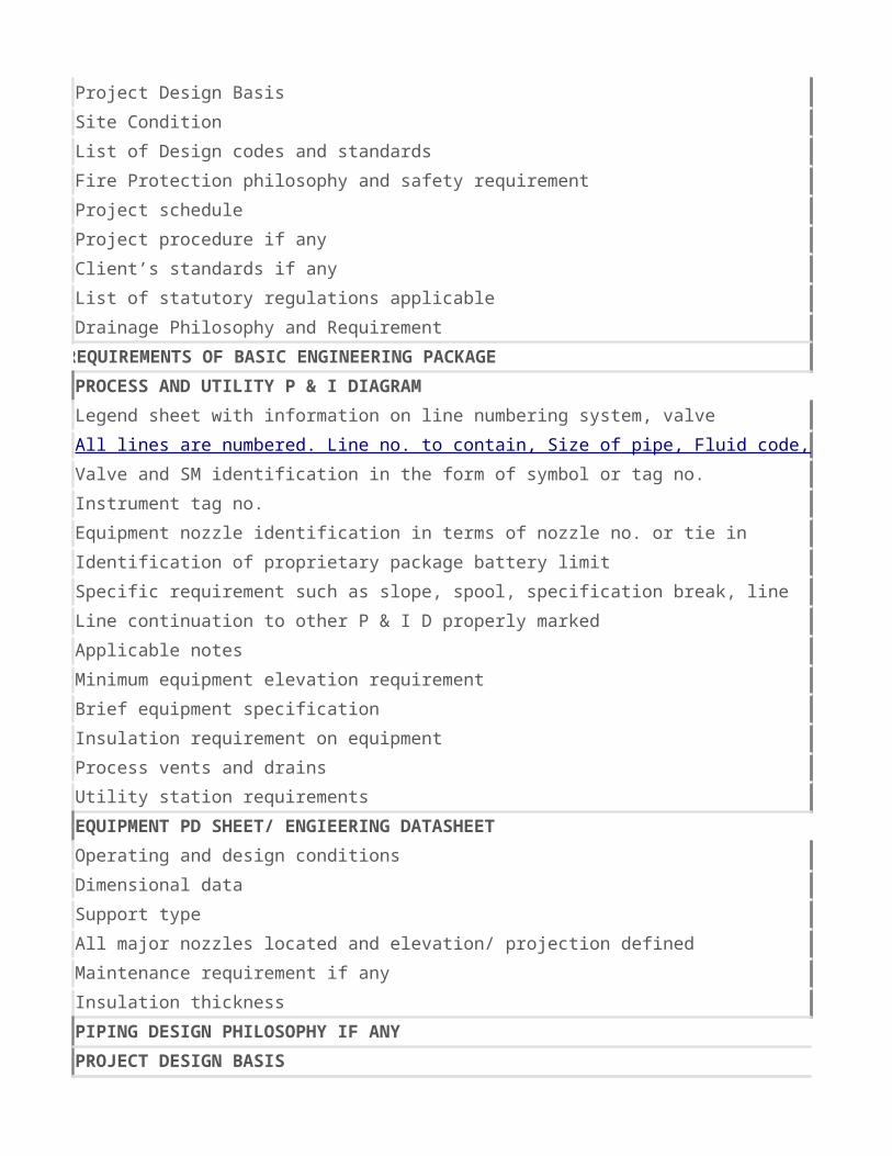
Fire Protection philosophy and safety requirement
Project schedule
Project procedure if any
Client’s standards if any
List of statutory regulations applicable
Drainage Philosophy and Requirement
REVIEW REQUIREMENTS OF BASIC ENGINEERING PACKAGEPROCESS AND UTILITY P & I DIAGRAM
Valve and SM identification in the form of symbol or tag no.
Instrument tag no.
Equipment nozzle identification in terms of nozzle no. or tie in point no.
Identification of proprietary package battery limit
Line continuation to other P & I D properly marked
Applicable notes
Minimum equipment elevation requirement
Brief equipment specification
Insulation requirement on equipment
Process vents and drains
Utility station requirements
EQUIPMENT PD SHEET/ ENGIEERING DATASHEETOperating and design conditions
Dimensional data
Support type
All major nozzles located and elevation/ projection defined
Maintenance requirement if any
Insulation thickness
PIPING DESIGN PHILOSOPHY IF ANYPROJECT DESIGN BASISSTRESS and SUPPORT DESIGN PHILOSOPHY IF ANY3 D DESIGN PHILOSOPHY IF ANYLINE LIST FOR AVAILABILITY OF DATAListPLOT PLANFunctional and Process Point of view
Legend sheet with information on line numbering system, valve identification system, SM numbering, Instrument numbering, Process specific requirement, Instrument process hook up requirement etcAll lines are numbered. Line no. to contain, Size of pipe, Fluid code, Line sequence no., Piping material specification, Insulation/ Painting/ Heat tracing/ Jacketing requirement, Area no. if any as minimum.
Specific requirement such as slope, spool, specification break, line routing criteria, gravity drain, barometric leg requirement, Valve/ Instrument location criteria etc.
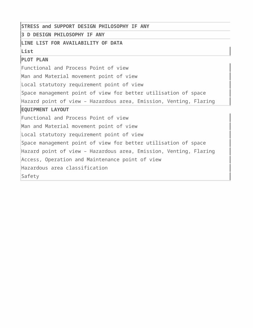
Man and Material movement point of view
Local statutory requirement point of view
Space management point of view for better utilisation of space
Hazard point of view – Hazardous area, Emission, Venting, Flaring etc.
EQUIPMENT LAYOUTFunctional and Process Point of view
Man and Material movement point of view
Local statutory requirement point of view
Space management point of view for better utilisation of space
Hazard point of view – Hazardous area, Emission, Venting, Flaring etc.
Access, Operation and Maintenance point of view
Hazardous area classification
Safety

Check List – Basic Engineering Package (BEP) Information Input/ Review

Check List – (Piping) Project Start/ Kick-Off Meeting Discussion
Sr. No.
1
2
3
4
5
6
7
8
9
10
11
12
Sr. No.
1
2
3
4

5
6
7
8


Check List – (Piping) Project Start/ Kick-Off Meeting Discussion
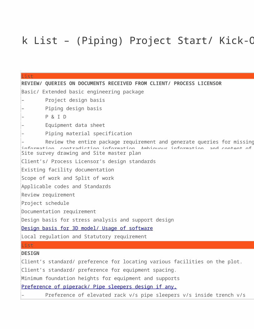
List
Basic/ Extended basic engineering package
Site survey drawing and Site master plan
Client’s/ Process Licensor’s design standards
Existing facility documentation
Scope of work and Split of work
Applicable codes and Standards
Review requirement
Project schedule
Documentation requirement
Design basis for stress analysis and support design
Local regulation and Statutory requirement
ListDESIGNClient’s standard/ preference for locating various facilities on the plot.
Client’s standard/ preference for equipment spacing.
Minimum foundation heights for equipment and supports
REVIEW/ QUERIES ON DOCUMENTS RECEIVED FROM CLIENT/ PROCESS LICENSOR
– Project design basis
– Piping design basis
– P & I D
– Equipment data sheet
– Piping material specification
– Review the entire package requirement and generate queries for missing information, contradicting information, Ambiguous information, and content of information.
Design basis for 3D model/ Usage of software
Preference of piperack/ Pipe sleepers design if any,
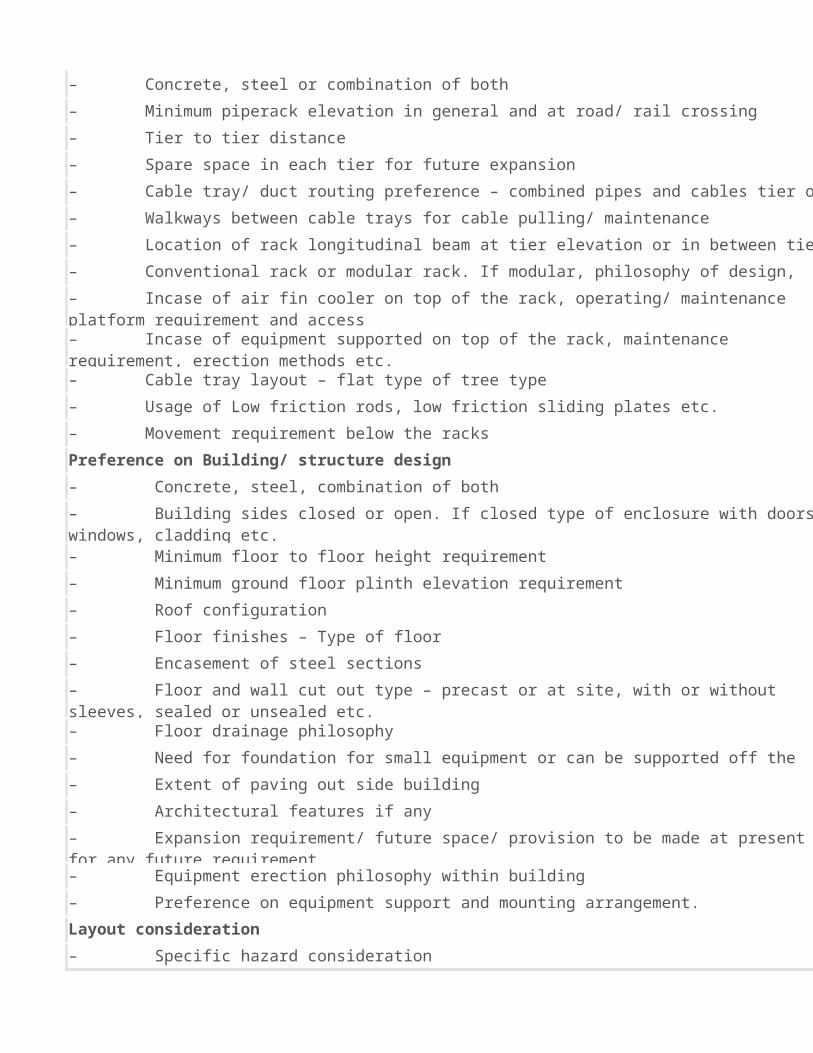
– Preference of elevated rack v/s pipe sleepers v/s inside trench v/s buried pipes and extent of the same– Concrete, steel or combination of both
– Minimum piperack elevation in general and at road/ rail crossing
– Tier to tier distance
– Spare space in each tier for future expansion

Preference on Building/ structure design
Layout consideration
– Cable tray/ duct routing preference – combined pipes and cables tier or separate?
– Walkways between cable trays for cable pulling/ maintenance
– Location of rack longitudinal beam at tier elevation or in between tier elevation.
– Conventional rack or modular rack. If modular, philosophy of design, erection etc.
– Incase of air fin cooler on top of the rack, operating/ maintenance platform requirement and access– Incase of equipment supported on top of the rack, maintenance requirement, erection methods etc.– Cable tray layout – flat type of tree type
– Usage of Low friction rods, low friction sliding plates etc.
– Movement requirement below the racks
– Concrete, steel, combination of both
– Building sides closed or open. If closed type of enclosure with doors windows, cladding etc.– Minimum floor to floor height requirement
– Minimum ground floor plinth elevation requirement
– Roof configuration
– Floor finishes – Type of floor
– Encasement of steel sections
– Floor and wall cut out type – precast or at site, with or without sleeves, sealed or unsealed etc.– Floor drainage philosophy
– Need for foundation for small equipment or can be supported off the floor
– Extent of paving out side building
– Architectural features if any
– Expansion requirement/ future space/ provision to be made at present for any future requirement.– Equipment erection philosophy within building
– Preference on equipment support and mounting arrangement.
– Specific hazard consideration
– Maintenance requirement such as crane, monorail, lifting beams etc.
– Road width, roads cross-section and type of road etc.
– Future expansion provision and consideration
– Operating access requirement for instrument valves manways, handholes etc.
– Storage warehouse sizes, no. of days storage for raw material, intermediate, finished product, waste, by products etc. and their loading and unloading consideration”– Non plant facilities requirement
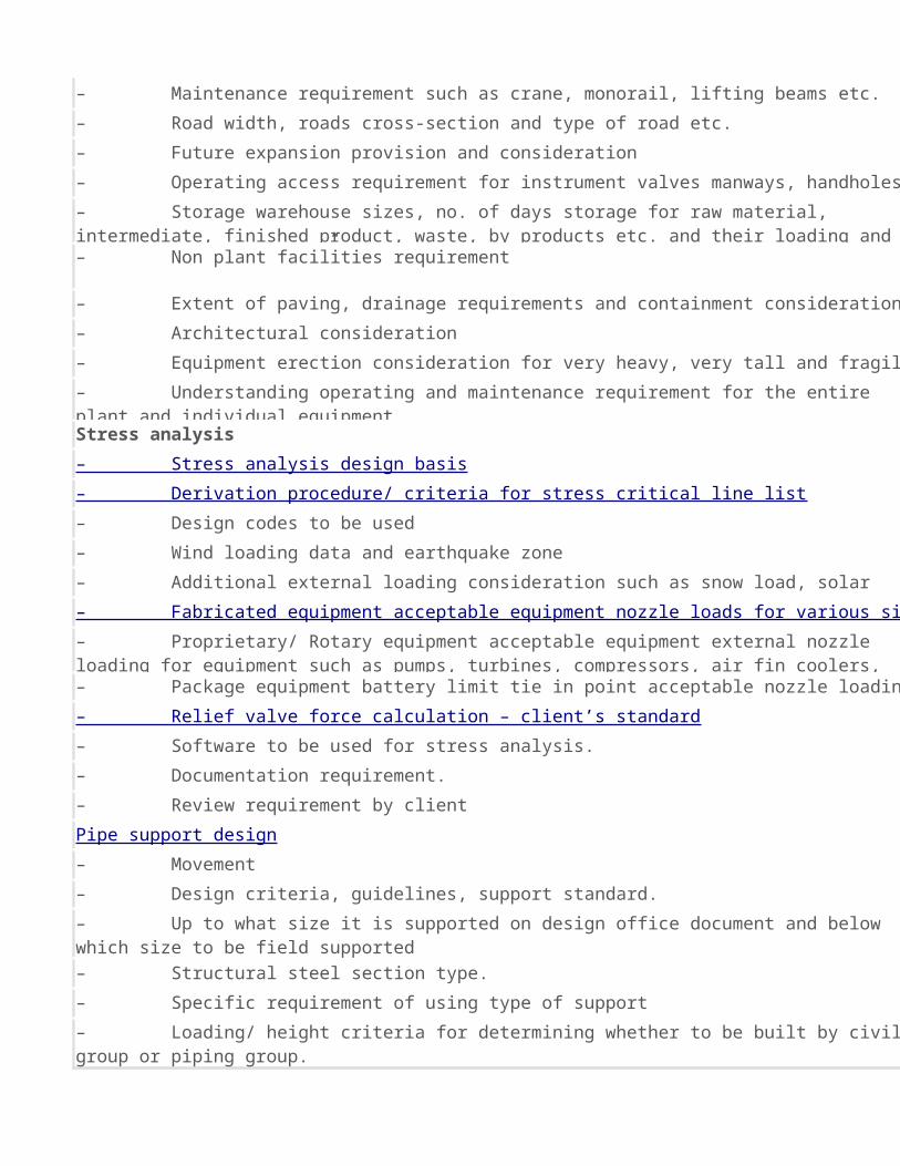
Stress analysis
– Extent of paving, drainage requirements and containment consideration.
– Architectural consideration
– Equipment erection consideration for very heavy, very tall and fragile equipment.
– Understanding operating and maintenance requirement for the entire plant and individual equipment
– Stress analysis design basis
– Derivation procedure/ criteria for stress critical line list
– Design codes to be used
– Wind loading data and earthquake zone
– Additional external loading consideration such as snow load, solar effect etc.– Fabricated equipment acceptable equipment nozzle loads for various sizes and pound rating nozzles
– Proprietary/ Rotary equipment acceptable equipment external nozzle loading for equipment such as pumps, turbines, compressors, air fin coolers, fired heaters etc– Package equipment battery limit tie in point acceptable nozzle loading– Relief valve force calculation – client’s standard
– Software to be used for stress analysis.
– Documentation requirement.
– Review requirement by clientPipe support design
– Movement
– Design criteria, guidelines, support standard.
– Up to what size it is supported on design office document and below which size to be field supported
– Structural steel section type.
– Specific requirement of using type of support
– Loading/ height criteria for determining whether to be built by civil group or piping group.
– Probable vendor for spring
– Usage of low friction slide plates in supports near critical equipment, high expansion area etc– Vessel supported pipes – cleat, standard, design
– Documentation requirement :
Pipe support on model – annotation or actual support Pipe support on isometrics or on layout
Special pipe supports
Support MTO
Support design software
Check List – (Piping) Project Start/ Kick-Off Meeting Discussion


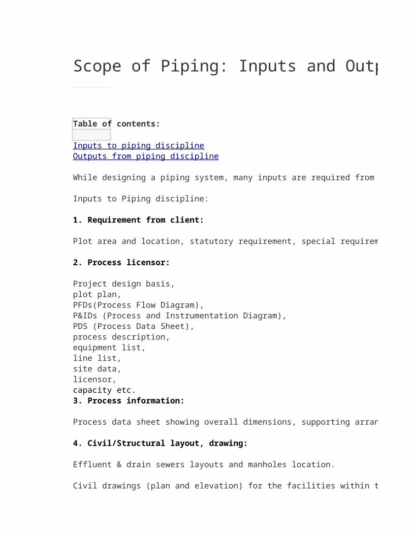
Scope of Piping: Inputs and Outputs
Table of contents:
While designing a piping system, many inputs are required from other disciplines and also inputs are given to other disciplines. There are also few outputs generated by piping which are required for procurement, erection and fabrication of the piping system.
Inputs to Piping discipline:
1. Requirement from client:
Plot area and location, statutory requirement, special requirements etc.
2. Process licensor:
Project design basis,plot plan, PFDs(Process Flow Diagram), P&IDs (Process and Instrumentation Diagram), PDS (Process Data Sheet), process description, equipment list, line list, site data,licensor,capacity etc.3. Process information:
Process data sheet showing overall dimensions, supporting arrangement, all nozzles location, size, rating, etc. for equipment.
4. Civil/Structural layout, drawing:
Effluent & drain sewers layouts and manholes location.
Civil drawings (plan and elevation) for the facilities within the unit like instrumentation control room, electrical sub-station, and laboratory.
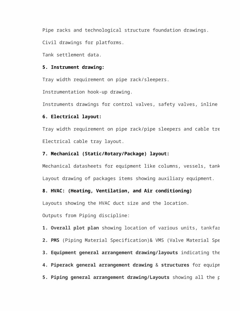
Pipe racks and technological structure foundation drawings.
Inputs to piping disciplineOutputs from piping discipline

Civil drawings for platforms.
Tank settlement data.
5. Instrument drawing:
Tray width requirement on pipe rack/sleepers.
Instrumentation hook-up drawing.
Instruments drawings for control valves, safety valves, inline instruments etc.
6. Electrical layout:
Tray width requirement on pipe rack/pipe sleepers and cable trenches width in units/off-site.
Electrical cable tray layout.
7. Mechanical (Static/Rotary/Package) layout:
Mechanical datasheets for equipment like columns, vessels, tanks etc.
Layout drawing of packages items showing auxiliary equipment.
8. HVAC: (Heating, Ventilation, and Air conditioning)
Layouts showing the HVAC duct size and the location.
Outputs from Piping discipline:
1. Overall plot plan showing location of various units, tankfarms, offsite, package units, non-plant buildings, roads, culverts, piperacks, sleepers, etc.
2. PMS (Piping Material Specification)& VMS (Valve Material Specification).
3. Equipment general arrangement drawing/layouts indicating the location of all the equipment within the unit, platforms , ladders, overhead crane elevation, monorail location, cutouts for piping.
4. Piperack general arrangement drawing & structures for equipment support
5. Piping general arrangement drawing/Layouts showing all the piping and equipment.
6. Piping Bill of Materials (BOM) with technical evaluation and technical bid analysis (TBA).
7. Piping stress analysis report for the critical lines.
8. Drawing showing the vessel cleats location for pipe supports and platform/ladder.
9. Layout for underground services.
10. Piping isometrics with bill of material.
11. Support location plan, support schedule, pipe support drawings.
12. Purchase specification for insulation, painting, wrapping and coating.
13. Material handling study.
While designing a piping system, many inputs are required from other disciplines and also inputs are given to other disciplines. There are also few outputs generated by piping which are required for procurement, erection and fabrication of the piping system.
Process data sheet showing overall dimensions, supporting arrangement, all nozzles location, size, rating, etc. for equipment.
Civil drawings (plan and elevation) for the facilities within the unit like instrumentation control room, electrical sub-station, and laboratory.

Tray width requirement on pipe rack/pipe sleepers and cable trenches width in units/off-site.
, offsite, package units, non-plant buildings, roads, culverts, piperacks, sleepers, etc.
indicating the location of all the equipment within the unit, platforms , ladders, overhead crane elevation, monorail location, cutouts for piping.
showing all the piping and equipment.
(BOM) with technical evaluation and technical bid analysis (TBA).
While designing a piping system, many inputs are required from other disciplines and also inputs are given to other disciplines. There are also few outputs generated by piping which are required for procurement, erection and fabrication of the piping system.
indicating the location of all the equipment within the unit, platforms , ladders, overhead crane elevation, monorail location, cutouts for piping.