check point™ provider-1/sitemanager-1® user guide
TRANSCRIPT

Check Point™Provider-1/SiteManager-1®User Guide
Version NGX R61
February 2006


© 2003-2006 Check Point Software Technologies Ltd.
All rights reserved. This product and related documentation are protected by copyright and distributed under licensing restricting their use, copying, distribution, and decompilation. No part of this product or related documentation may be reproduced in any form or by any means without prior written authorization of Check Point. While every precaution has been taken in the preparation of this book, Check Point assumes no responsibility for errors or omissions. This publication and features described herein are subject to change without notice.
RESTRICTED RIGHTS LEGEND:
Use, duplication, or disclosure by the government is subject to restrictions as set forth in subparagraph (c)(1)(ii) of the Rights in Technical Data and Computer Software clause at DFARS 252.227-7013 and FAR 52.227-19.
TRADEMARKS:
©2003-2006 Check Point Software Technologies Ltd. All rights reserved.
Check Point, Application Intelligence, Check Point Express, the Check Point logo, AlertAdvisor, ClusterXL, Cooperative Enforcement, ConnectControl, Connectra, CoSa, Cooperative Security Alliance, Eventia, Eventia Analyzer, FireWall-1, FireWall-1 GX, FireWall-1 SecureServer, FloodGate-1, Hacker ID, IMsecure, INSPECT, INSPECT XL, Integrity, InterSpect, IQ Engine, Open Security Extension, OPSEC, Policy Lifecycle Management, Provider-1, Safe@Home, Safe@Office, SecureClient, SecureKnowledge, SecurePlatform, SecuRemote, SecureXL Turbocard, SecureServer, SecureUpdate, SecureXL, SiteManager-1, SmartCenter, SmartCenter Pro, Smarter Security, SmartDashboard, SmartDefense, SmartLSM, SmartMap, SmartUpdate, SmartView, SmartView Monitor, SmartView Reporter, SmartView Status, SmartViewTracker, SofaWare, SSL Network Extender, Stateful Clustering, TrueVector, Turbocard, UAM, User-to-Address Mapping, UserAuthority, VPN-1, VPN-1 Accelerator Card, VPN-1 Edge, VPN-1 Pro, VPN-1 SecureClient, VPN-1 SecuRemote, VPN-1 SecureServer, VPN-1 VSX, VPN-1 XL, Web Intelligence, ZoneAlarm, ZoneAlarm Pro, Zone Labs, and the Zone Labs logo, are trademarks or registered trademarks of Check Point Software Technologies Ltd. or its affiliates. All other product names mentioned herein are trademarks or registered trademarks of their respective owners. The products described in this document are protected by U.S. Patent No. 5,606,668, 5,835,726, 6,496,935 and 6,850,943 and may be protected by other U.S. Patents, foreign patents, or pending applications.
For third party notices, see THIRD PARTY TRADEMARKS AND COPYRIGHTS.


Table of Contents 5
Table Of Contents
Preface Who Should Use This Guide.............................................................................. 12Summary of Contents ....................................................................................... 13Related Documentation .................................................................................... 14More Information ............................................................................................. 17
Chapter 1 Introduction The Need for Provider-1/SiteManager-1 ............................................................. 20
Management Service Providers (MSP) ........................................................... 21Data Centers .............................................................................................. 23Large Enterprises........................................................................................ 23
The Check Point Solution ................................................................................. 26Basic Elements........................................................................................... 27Point of Presence (POP) Network Environment............................................... 31Managers and Containers............................................................................. 33Log Managers ............................................................................................. 36High Availability ......................................................................................... 38Security Policies in Provider-1 ..................................................................... 39
The Management Model ................................................................................... 40Introduction to the Management Model......................................................... 40Administrators ............................................................................................ 40Management Tools ...................................................................................... 42
The Provider-1/SiteManager-1 Trust Model......................................................... 48Introduction to the Trust Model .................................................................... 48Secure Internal Communication (SIC) ........................................................... 48Trust Between a CMA and its Customer Network ............................................ 49Trust Between a CLM and its Customer Network ............................................ 50MDS Communication with CMAs .................................................................. 51Trust Between MDS to MDS......................................................................... 51Authenticating the Administrator .................................................................. 51Authenticating via External Authentication Servers......................................... 52Setting up External Authentication ............................................................... 54Re-authenticating when using SmartConsole Clients....................................... 55CPMI Protocol ............................................................................................ 57
Chapter 2 Planning the Provider-1 Environment Asking yourself the right questions... ................................................................. 61Consider the Following Scenario... ..................................................................... 63Protecting the Provider-1/SiteManager-1 Network ............................................... 65MDS Managers and Containers.......................................................................... 66
MDS Managers ........................................................................................... 66MDS Containers.......................................................................................... 66Choosing your deployment for MDS Managers and Containers ......................... 67

6
MDS Clock Synchronization ......................................................................... 68Setting up the Provider-1/SiteManager-1 Environment......................................... 69
A Typical Scenario ...................................................................................... 69A Standalone Provider-1/SiteManager-1 Network ........................................... 70A Distributed Provider-1/SiteManager-1 Network............................................ 71Provider-1/SiteManager-1 Network with Point of Presence (POP) Center........... 72
Hardware Requirements and Recommendations.................................................. 74Provider-1/SiteManager-1 Order of Installation ................................................... 75Licensing and Deployment................................................................................ 76
The Trial Period.......................................................................................... 76Considerations............................................................................................ 76Further Licensing Detail .............................................................................. 78
Miscellaneous Issues ....................................................................................... 82IP Allocation & Routing ............................................................................... 82Network Address Translation (NAT) .............................................................. 83Enabling OPSEC......................................................................................... 84
Chapter 3 Provisioning the Provider-1 Environment Overview ......................................................................................................... 86The Provisioning Process .................................................................................. 87Installation and Configuration ........................................................................... 88
Supported Platforms for the MDS................................................................. 88Minimal Hardware Requirements and Disk Space .......................................... 88Installing the MDS - Creating a Primary Manager ........................................... 89Uninstall the MDS ...................................................................................... 91Entering the MDS License ........................................................................... 91Install the MDG and SmartConsole Clients .................................................... 93
Using the MDG for the First Time...................................................................... 95To Launch the MDG.................................................................................... 95
Defining a Security Policy for the Provider-1 Gateway.......................................... 97Enabling Connections Between Different Components of the System ............... 98
Configurations with More than One MDS .......................................................... 101MDS Clock Synchronization ....................................................................... 101Adding an MDS (Container, Manager, or both), or MLM ................................ 102Editing or Deleting an MDS ....................................................................... 104
When the VPN-1 Pro Gateway is Standalone..................................................... 105When a CMA Manages the VPN-1 Pro Gateway ................................................. 106
Starting the Add Customer Wizard .............................................................. 107OPSEC Application Connections...................................................................... 108
Connecting with an OPSEC Application Client to all Customers ..................... 108Connecting with an OPSEC Application Client to a Single Customer............... 109
Chapter 4 High-Level Customer Management Overview ....................................................................................................... 112
Creating Customers: A Sample Deployment ................................................. 114Inputting Licenses using the MDG.............................................................. 122
Setup Considerations ..................................................................................... 125IP Allocation for CMAs .............................................................................. 125

Table of Contents 7
Assigning Groups ...................................................................................... 125Configuration................................................................................................. 126
Configuring a New Customer ...................................................................... 126Creating Administrator and Customer Groups............................................... 129Changing Administrators............................................................................ 129Modifying a Customer’s Configuration ......................................................... 131Changing GUI Clients ................................................................................ 131Deleting a Customer.................................................................................. 132Configuring a CMA.................................................................................... 132Starting or Stopping a CMA........................................................................ 132Checking CMA Status................................................................................ 132Deleting a CMA ........................................................................................ 133
Chapter 5 Global Policy Management Security Policies in Provider-1 ........................................................................ 136
Introduction to Security Policies in Provider-1 ............................................. 136The Need for Global Policies ...................................................................... 138The Global Policy as a Template................................................................. 139Global Policies and the Global Rule Base .................................................... 140
Global SmartDashboard.................................................................................. 142Introduction to Global SmartDashboard....................................................... 142Global Services......................................................................................... 143Dynamic Objects and Dynamic Global Objects ............................................. 143Synchronizing the Global Policy Database ................................................... 144
Creating a Global Policy through Global SmartDashboard................................... 145Global SmartDefense...................................................................................... 147
Introduction to Global SmartDefense .......................................................... 147Configuring SmartDefense in Global SmartDashboard................................... 147Subscribing a Customer to the Global SmartDefense Service......................... 148Modifying SmartDefense from the SmartDashboard of a CMA........................ 150
Assigning Global Policy .................................................................................. 152Introduction to Assigning Global Policy ....................................................... 152Assigning Global Policy for the First Time.................................................... 152Reassigning Global Policy .......................................................................... 153Reassigning Global Policy to Multiple Customers Simultaneously................... 153Reviewing the Status of Global Policy Assignments ...................................... 154Considerations For Global Policy Assignment ............................................... 155Global Policy History File........................................................................... 157
Configuration................................................................................................. 158Assign/Install a Global Policy ..................................................................... 158Reassigning/Installing a Global Policy on Customers..................................... 159Reinstalling a Customer Policy onto the Customers’ Gateways ....................... 160Remove a Global Policy from Multiple Customers......................................... 161Remove a Global Policy from a Single Customer........................................... 161Viewing the Customer’s Global Policy History File ........................................ 161Global Policies Tab ................................................................................... 161Global Names Format................................................................................ 162

8
Chapter 6 Working in the Customer’s Network Overview ....................................................................................................... 164
Customer Management Add-on (CMA)......................................................... 164Administrators .......................................................................................... 165SmartConsole Client Applications ............................................................... 165
Installing and Configuring for VPN-1 Pro Gateways ........................................... 167Managing Customer Policies ........................................................................... 168
VPN-1 Edge/Embedded Appliances ............................................................ 168Creating Customer Policies ........................................................................ 168Revision Control ....................................................................................... 168
Working with CMAs and CLMs in the MDG ....................................................... 169
Chapter 7 Logging in Provider-1 Logging Customer Activity .............................................................................. 172Exporting Logs............................................................................................... 176
Log Export to Text..................................................................................... 176Manual Log Export to Oracle Database ........................................................ 176Automatic Log Export to Oracle Database .................................................... 177Log Forwarding ......................................................................................... 178Cross Domain Logging ............................................................................... 178
Logging Configuration .................................................................................... 179Setting Up Logging ................................................................................... 179Working with CLMs ................................................................................... 180Setting up Customer Module to Send Logs to the CLM ................................. 181Synchronizing the CLM Database with the CMA Database ............................. 182Configuring an MDS to Enable Log Export ................................................... 182Configuring Log Export Profiles .................................................................. 182Choosing Log Export Fields ........................................................................ 183Log Export Troubleshooting........................................................................ 184Using Eventia Reporter.............................................................................. 185
Chapter 8 VPN in Provider-1 Overview ....................................................................................................... 188
Access Control at the Network Boundary ..................................................... 189Authentication Between Gateways .............................................................. 189How VPN Works........................................................................................ 190
VPN-1 Connectivity in Provider-1 .................................................................... 193VPN-1 Connections for a Customer Network ................................................ 193
Global VPN Communities................................................................................ 197Gateway Global Names.............................................................................. 197VPN Domains in Global VPN ...................................................................... 198Access Control at the Network Boundary ..................................................... 199Access Control and Global VPN Communities .............................................. 199Joining a Gateway to a Global VPN Community ............................................ 200
Configuring Global VPN Communities .............................................................. 202
Chapter 9 Monitoring in Provider-1

Table of Contents 9
Overview ....................................................................................................... 206Monitoring Components in the Provider-1 System ............................................. 207
Exporting the List Pane’s Information to an External File .............................. 208Working with the List Pane ........................................................................ 208
Checking the Status of Components in the System............................................ 209Viewing Status Details............................................................................... 211Locating Components with Problems........................................................... 211
Monitoring Issues for Different Components and Features .................................. 213MDS........................................................................................................ 213Global Policies ......................................................................................... 215Customer Policies ..................................................................................... 216Module Policies ........................................................................................ 216High Availability ....................................................................................... 217Global VPN Communities........................................................................... 218Administrators .......................................................................................... 219GUI Clients .............................................................................................. 220
Using SmartConsole to Monitor Customer’s Network Activity .............................. 222Setting up Log Tracking in Provider-1 ......................................................... 222Tracking Logs with SmartView Tracker ........................................................ 222Eventia Reporter Reports ........................................................................... 225
Chapter 10 High Availability Overview ....................................................................................................... 228CMA High Availability..................................................................................... 229
Active Versus Standby ............................................................................... 231Setting up a Mirror CMA............................................................................ 232CMA Backup using SmartCenter Server....................................................... 232
MDS High Availability .................................................................................... 235MDS Mirror Site........................................................................................ 235MDS Managers ......................................................................................... 236Setting up a New MDS and Initiating Synchronization .................................. 237MDS: Active or Standby............................................................................. 237The MDS Manager’s Databases .................................................................. 238The MDS Container’s Databases ................................................................. 239How Synchronization Works ....................................................................... 239Setting up Synchronization ........................................................................ 242
Configuration................................................................................................. 245Adding another MDS ................................................................................. 245Creating a Mirror of an Existing MDS .......................................................... 246Initializing Synchronization between MDSs.................................................. 247Subsequent Synchronization for MDSs........................................................ 247Selecting a Different MDS to be the Active MDS.......................................... 248Automatic Synchronization for Global Policies Databases.............................. 248Add a Secondary CMA............................................................................... 248Automatic CMA Synchronization................................................................. 249Synchronize ClusterXL Modules.................................................................. 249
Chapter 11 Architecture and Processes

10
Packages in MDS Installation.......................................................................... 252Packages in Common MDS Installation ....................................................... 252Packages in MDS Upgrade......................................................................... 253Eventia Reporter Add-on............................................................................ 253
MDS File System ........................................................................................... 254MDS Directories on /opt and /var File Systems ............................................. 254Structure of CMA Directory Trees ............................................................... 255Check Point Registry ................................................................................. 256Automatic Start of MDS Processes, Files in /etc/rc3.d, /etc/init.d................... 256
Processes...................................................................................................... 257Environment Variables............................................................................... 257MDS Level Processes ................................................................................ 259CMA Level Processes ................................................................................ 260
MDS Configuration Databases ......................................................................... 261Global Policy Database.............................................................................. 261MDS Database.......................................................................................... 261CMA Database.......................................................................................... 262
Connectivity Between Different Processes ........................................................ 263MDS Connection to CMAs.......................................................................... 263Status Collection ...................................................................................... 264Collection of Changes in Objects ................................................................ 264Connection Between MDSs ........................................................................ 265Large Scale Management Processes............................................................ 265VPN-1 Edge Processes .............................................................................. 265Reporting Server Processes ........................................................................ 265
Issues Relating to Different Platforms.............................................................. 266High Availability Scenarios ........................................................................ 266Migration Between Platforms ..................................................................... 267
Chapter 12 Commands and Utilities
Index.......................................................................................................... 309

11
Preface PPreface
In This Chapter
Who Should Use This Guide page 12
Summary of Contents page 13
Related Documentation page 14
More Information page 17

Who Should Use This Guide
12
Who Should Use This GuideThis guide is intended for administrators responsible for maintaining network security within an enterprise, including policy management and user support.
This guide assumes a basic understanding of
• System administration.
• The underlying operating system.
• Internet protocols (IP, TCP, UDP etc.).
Summary of Contents
Preface 13
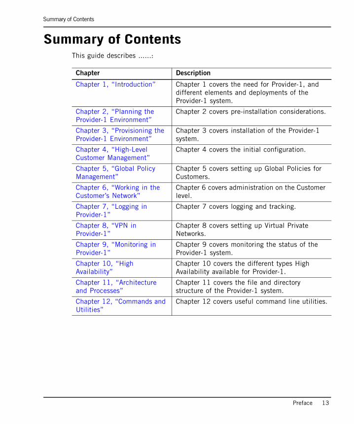
Summary of ContentsThis guide describes ......:
Chapter Description
Chapter 1, “Introduction” Chapter 1 covers the need for Provider-1, and different elements and deployments of the Provider-1 system.
Chapter 2, “Planning the Provider-1 Environment”
Chapter 2 covers pre-installation considerations.
Chapter 3, “Provisioning the Provider-1 Environment”
Chapter 3 covers installation of the Provider-1 system.
Chapter 4, “High-Level Customer Management”
Chapter 4 covers the initial configuration.
Chapter 5, “Global Policy Management”
Chapter 5 covers setting up Global Policies for Customers.
Chapter 6, “Working in the Customer’s Network”
Chapter 6 covers administration on the Customer level.
Chapter 7, “Logging in Provider-1”
Chapter 7 covers logging and tracking.
Chapter 8, “VPN in Provider-1”
Chapter 8 covers setting up Virtual Private Networks.
Chapter 9, “Monitoring in Provider-1”
Chapter 9 covers monitoring the status of the Provider-1 system.
Chapter 10, “High Availability”
Chapter 10 covers the different types High Availability available for Provider-1.
Chapter 11, “Architecture and Processes”
Chapter 11 covers the file and directory structure of the Provider-1 system.
Chapter 12, “Commands and Utilities”
Chapter 12 covers useful command line utilities.

Related Documentation
14
Related DocumentationThe NGX R61 release includes the following documentation
TABLE P-1 VPN-1 Pro documentation suite documentation
Title Description
Getting Started Guide Contains an overview of NGX R61 and step by step product installation and upgrade procedures. This document also provides information about What’s New, Licenses, Minimum hardware and software requirements, etc.
Upgrade Guide Explains all available upgrade paths for Check Point products from VPN-1/FireWall-1 NG forward. This guide is specifically geared towards upgrading to NGX R61.
SmartCenter Guide Explains SmartCenter Management solutions. This guide provides solutions for control over configuring, managing, and monitoring security deployments at the perimeter, inside the network, at all user endpoints.
Firewall and SmartDefense Guide
Describes how to control and secure network access; establish network connectivity; use SmartDefense to protect against network and application level attacks; use Web Intelligence to protect web servers and applications; the integrated web security capabilities; use Content Vectoring Protocol (CVP) applications for anti-virus protection, and URL Filtering (UFP) applications for limiting access to web sites; secure VoIP traffic
Eventia Reporter Explains how to monitor and audit traffic, and generate detailed or summarized reports in the format of your choice (list, vertical bar, pie chart etc.) for all events logged by Check Point VPN-1 Pro, SecureClient and SmartDefense.

Related Documentation
Preface 15
SmartView Tracker Guide.
Provides information about how to collect comprehensive information on your network activity in the form of logs. Learn how to use SmartView Tracker to audit these logs at any given time, analyze traffic patterns and troubleshoot networking and security issues.
SecurePlatform Guide Explains how to install and configure SecurePlatform. This guide will also teach you how to manage your SecurePlatform and explains Dynamic Routing (Unicast and Multicast) protocols.
Provider-1 Guide Explains the Provider-1/SiteManager-1 security management solution. This guide provides details about a three-tier, multi-policy management architecture and a host of Network Operating Center oriented features that automate time-consuming repetitive tasks common in Network Operating Center environments.
TABLE P-2 Integrity Server documentation
Title Description
Integrity Advanced Server Installation Guide
Explains how to install, configure, and maintain the Integrity Advanced Server.
Integrity Advanced Server Administrator Console Reference
Provides screen-by-screen descriptions of user interface elements, with cross-references to relevant chapters of the Administrator Guide. This document contains an overview of Administrator Console navigation, including use of the help system.
Integrity Advanced Server Administrator Guide
Explains how to managing administrators and endpoint security with Integrity Advanced Server.
Integrity Advanced Server Gateway Integration Guide
Provides information about how to integrating your Virtual Private Network gateway device with Integrity Advanced Server. This guide also contains information regarding deploying the unified SecureClient/Integrity client package.
TABLE P-1 VPN-1 Pro documentation suite documentation (continued)
Title Description

Related Documentation
16
Integrity Advanced Server System Requirements
Provides information about client and server requirements.
Integrity Agent for Linux Installation and Configuration Guide
Explains how to install and configure Integrity Agent for Linux.
Integrity XML Policy Reference Guide
Provides the contents of Integrity client XML policy files.
Integrity Client Management Guide
Explains how to use of command line parameters to control Integrity client installer behavior and post-installation behavior.
TABLE P-2 Integrity Server documentation (continued)
Title Description

More Information
Preface 17
More Information• For additional technical information about Check Point products, consult Check
Point’s SecureKnowledge at https://secureknowledge.checkpoint.com/.
• See the latest version of this document in the User Center at http://www.checkpoint.com/support/technical/documents

More Information
18

19
Chapter 1Introduction
In This Chapter
The Need for Provider-1/SiteManager-1 page 20
The Check Point Solution page 26
The Management Model page 40
The Provider-1/SiteManager-1 Trust Model page 48

The Need for Provider-1/SiteManager-1
20
The Need for Provider-1/SiteManager-1In This Section
Secured IT systems are a basic need for modern business environments, and large deployments face unique security challenges. A large scale enterprise must handle the challenges of disparate yet interconnected systems. The large scale enterprise often has corporate security policies that must be tailored to local branch needs, balanced with vital requirement for corporate-wide access, perhaps between branches in different countries.
Businesses with a large user base often need to monitor and control access to confidential internal sites, and to monitor communication failures. Administrators must be alerted to external attacks, not only on a company-wide basis, but also more selectively on a department by department, branch by branch basis.
Companies with many branches must face security and access challenges that small scale businesses do not. For example, an international airline needs to provide access of varying levels to ticket agents, managers, airline staff, and customers, through the Internet, intranets both local and international, and through remote dial-up; all the while preventing unauthorized access to confidential financial data.
Differentiating between levels of access permissions is critical not only for securing user transactions, but also for monitoring for attacks, abuse and load management. Task specialization amongst administrators must also be supported so that security can be centralized.
Service providers such as Data Centers and Managed Service Providers (MSPs) need to securely manage large-scale systems with many different customers and access locations. An MSP must potentially handle separate customer systems with many different LANs, each with its own security policy needs. The MSP must be able to confidentially address the security and management needs for each customer, each with their own system topology and system products. One policy is not sufficient for the needs of so many different types of customers.
A Data Center provides data storage services to customers and must handle access and storage security for many different customers, whose requirements for private and secure access to their data are of critical importance.
Management Service Providers (MSP) page 21
Data Centers page 23
Large Enterprises page 23

Management Service Providers (MSP)
Chapter 1 Introduction 21
We will examine a few basic scenarios: the MSP, the Data Center, and the large scale enterprise.
Management Service Providers (MSP)An MSP manages IT services, such as security and accessibility, for other companies, saving these companies the cost of an expert internal IT staff. A management system must accommodate the MSP’s own business needs, deploying an IT management architecture that scales to support a rapidly growing customer base, while minimizing support procedures and dedicated hardware.
The MSP handles many different customer systems, which creates a variety of IT management needs. Home users may require basic Internet services, with security managed by VPN-1 Edge/Embedded appliances. Small companies may require Internet and customized-security coverage; others want autonomy to manage their own security policies. One small company wants to protect its computers with a single enforcement point, a VPN-1 Pro gateway, while another requires gateways and security services for several offices and multiple networks which must communicate securely and privately.
While the MSP must have administrators that can manage the entire MSP environment, administrators or individual customers must not have access to the environments of other customers.
Let’s examine the network of a fictitious MSP, SupportMSP:
Management Service Providers (MSP)
22
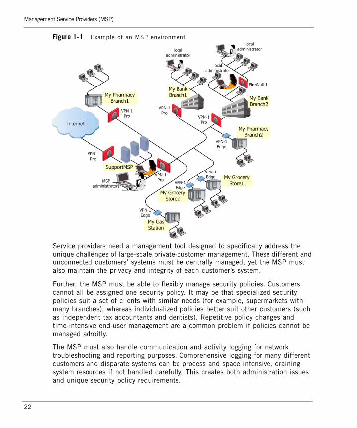
Figure 1-1 Example of an MSP environment
Service providers need a management tool designed to specifically address the unique challenges of large-scale private-customer management. These different and unconnected customers’ systems must be centrally managed, yet the MSP must also maintain the privacy and integrity of each customer’s system.
Further, the MSP must be able to flexibly manage security policies. Customers cannot all be assigned one security policy. It may be that specialized security policies suit a set of clients with similar needs (for example, supermarkets with many branches), whereas individualized policies better suit other customers (such as independent tax accountants and dentists). Repetitive policy changes and time-intensive end-user management are a common problem if policies cannot be managed adroitly.
The MSP must also handle communication and activity logging for network troubleshooting and reporting purposes. Comprehensive logging for many different customers and disparate systems can be process and space intensive, draining system resources if not handled carefully. This creates both administration issues and unique security policy requirements.

Data Centers
Chapter 1 Introduction 23
Data CentersThe data service provider is a type of service center, a company that provides computer data storage and related services, such as backup and archiving, for other companies. For example, let’s examine the network of a fictitious Data Center:Figure 1-2 Example of a Data Center
Similar to the MSP, the Data Center manages its own environment, whereas individual customer administrators and customers cannot have access to other customers' environments.
Large EnterprisesBusinesses that expand through lateral and horizontal integration, such as conglomerates or holding companies, face security policy challenges due to the diverse nature of their subsidiaries’ businesses. In these complex environments, security managers need the right tools to manage multiple policies efficiently. Central management of security policy changes, which are enforced by the different firewalls throughout the system, ensure that the entire corporate IT architecture is adequately protected.
Let’s look at a sample deployment for an automotive manufacturing concern:

Large Enterprises
24
Figure 1-3 Conglomerate’s network
Corporate IT departments must manage security services for a wide-spread system, with link-ups with vendors, external inventory systems, billing inputs, and reporting requirements. Different branches are geographically distributed and have independent network management. Yet the network security personnel must support a corporate-wide security policy, with rules enforcing access for appropriate users, preventing attacks, enabling secure communication and fail-over capabilities.
IT departments must often delegate levels of authority among administrators, so that there is a hierarchy of access even within systems support. Whereas some administrators will have global authorities to maintain the system backbone, others may handle specialized activities and only require permissions for certain parts of the system. For example, an IT support person in a manufacturing branch would not necessarily need to have total administrator privileges for the logistics headquarters network, and a vendor administrator that handles network maintenance would not need corporate- wide permissions.

Large Enterprises
Chapter 1 Introduction 25
IT services in large scale enterprises must often log network activity for security tracking purposes. Comprehensive logging can consume considerable system resources and slow down a corporate network, if not deployed with an appropriate solution. For enterprises with local and remote branches, centralized failover security management is another critical success factor in achieving efficient and comprehensive system security.
For Big Bank, different types of permissions and access management are required to protect internal networks and separate them from external networks accessible to users. Figure 1-4 Big Bank’s network

The Check Point Solution
26
The Check Point SolutionIn This Section
Check Point’s Provider-1/SiteManager-1 is the best-of-breed security management solution designed to meet the scalability requirements of service provider and large enterprise Network Operating Center environments. A unique three-tier, multi-policy management architecture and a host of Network Operating Center oriented features automate time-consuming repetitive tasks common in Network Operating Center environments. Provider-1/SiteManager-1 meets the needs of both the enterprise and of service providers serving the enterprise market. This solution dramatically reduces the administrative cost of managing large security deployments.
The basic three-tier security architecture of the VPN-1 Pro system, consisting of enforcement points, a management console, and a GUI, delivers a robust mechanism for creating firewall security policies and automatically distributing them to multiple enforcement points. Provider-1/SiteManager-1 supports central management for many distinct security policies simultaneously.
Companies envision horizontal growth throughout an industry, to implement economies of scale through incorporation of partner-companies and vendors. Enterprises want to manage vertical growth through product differentiation. Security management achieves a new level of customization and flexibility with Provider-1/SiteManager-1.
With Provider-1/SiteManager-1, security policies can be customized. Enterprises can, for example, tailor a security policy to enable vendor applications which tie into corporate financial networks to communicate safely and securely, yet without having access to confidential corporate data. As another example, a security policy can enable franchise companies to communicate with regional and international headquarters, yet safeguard the franchise internal network integrity.
Basic Elements page 27
Point of Presence (POP) Network Environment page 31
Managers and Containers page 33
Log Managers page 36
High Availability page 38
Security Policies in Provider-1 page 39

Basic Elements
Chapter 1 Introduction 27
An administrator can create policies for groups of customer firewalls, and/or create high-level global policies that manage all customer polices at once. The ability to set policy at every level, including both the customer and global level, delivers exceptional scalability by eliminating the need to recreate policies and policy changes, potentially to thousands of devices.
Basic Elements
In This Section
The Provider-1/SiteManager-1 system is designed to manage many widely distributed enforcement points, for networks that may belong to different customers, different companies, or different corporate branches.
The primary element of a security system is the enforcement point, the VPN-1 Pro gateway. Administrators decide how this firewall is to be managed and apply a security policy, with rules that determine how communication is handled by the firewall.
A Customer Management Add-On (CMA) is a virtual customer management. The CMA manages customer enforcement points, i.e., their firewalls. Through the CMA, an administrator creates policies for Customer gateways.
The Multi-Domain Server (MDS) houses the CMAs, as well as all of the Provider-1/SiteManager-1 system information. It contains the details of the Provider-1/SiteManager-1 network, its administrators, and high level customer management information.
The MDS can hold a substantial amount of customer network and policy detail on a single server, providing a powerful, centralized management node. Multiple MDSs can be linked in the Provider-1/SiteManager-1 system to manage thousands of policies in a single environment, and to provide fail-over capabilities.
Example: MSP Deployment page 28
Example: Enterprise Deployment page 29
Multi-Domain GUI page 31
Note - You may have noticed that the term Customer is capitalized in the preceding sentence. As a convention in this guide, the term Customer will appear as capitalized whenever referring to elements of the Provider-1/SiteManager-1 system.

Basic Elements
28
The CMA is the equivalent of a standalone SmartCenter server in the VPN-1 Pro model (see the VPN Guide and Firewall and SmartDefense Guide). But unlike the SmartCenter server, the CMA is a manager, located on the MDS. Although many CMAs can be stored on the same MDS, CMAs are completely isolated from each other, providing absolute customer privacy. In a large enterprise, each CMA may manage branch or department firewalls, depending on the security resolution required by the corporate security policy.
CMAs are located inside the Provider-1/SiteManager-1 environment. The VPN-1 Pro Module can be located in a separate network, in a separate city or country. Figure 1-5 Distributed Management Configuration
Example: MSP DeploymentLet’s examine the basic system components at a less granular level, looking at a start-up MSP setup with Provider-1. The service provider, Provider, has an MDS and an internal network, connected to the Internet and protected by a VPN-1 Pro gateway. This service provider offers security services to two customers, and manages their VPN-1 Pro gateways.

Basic Elements
Chapter 1 Introduction 29
Each customer has a VPN-1 Pro gateway protecting their respective internal corporate networks. Typing.com has one network with one firewall. TravelAgency has two branches, each protected by its own VPN-1 Pro gateway. Each Customer has its own CMA, which resides in the service provider’s MDS, inside the Provider-1/SiteManager-1 network environment.
Each CMA can manage more than one VPN-1 Pro gateway. TravelAgency has its own private CMA, that manages both of TravelAgency’s VPN-1 Pro gateways. Typing.Com also has its own private CMA, which manages its VPN-1 Pro gateway. TravelAgency cannot access information about the Typing.Com environment, nor about the service provider’s environment.
Notice that Provider also has a CMA to manage its own firewall. Figure 1-6 How CMAs manage VPN-1 Pro gateways
Example: Enterprise DeploymentWhereas a service provider manages individual customer networks, a large enterprise manages branches and departments. So, let’s consider a Provider-1/SiteManager-1 setup for an international accountancy firm. The firm has its corporate headquarters in London, with one branch office in Manchester, and

Basic Elements
30
another in Paris. Each of the branches have VPN-1 Pro gateways protecting internal corporate networks. Let us say that in this corporate environment, all security management is handled through the corporate headquarters in London.
How can this corporate system be protected? The branch offices are assigned CMAs to manage their gateways. In this case, the IT department is centralized in the corporate headquarters in London. An MDS has been created in London to manage the system. The Manchester corporate branch’s VPN-1 Pro gateway is handled by its own CMA. The Paris and Nice branches are both managed by another CMA. Although the MDS and the gateways themselves are in different cities and countries, management is centralized and handled by the IT department in the London office. Figure 1-7 Enterprise deployment

Point of Presence (POP) Network Environment
Chapter 1 Introduction 31
Multi-Domain GUIProvider-1/SiteManager-1 administrators use the Multi-Domain GUI (MDG) as the primary interface to handle customer security management. The MDG has many “views” tailored to display information relevant to specific tasks. Figure 1-8 MDG - Close-up
The MDG manages the entire Provider-1/SiteManager-1 environment, and provides an easy way to incorporate customers and their networks into the Provider-1/SiteManager-1 system. It is used to update Customer and gateway information, and to assign and navigate between global policies. Using the MDG, administrators can provision and monitor security through a single console, and oversee rules, policies, logs, statuses, and alerts for hundreds of customers.
Point of Presence (POP) Network EnvironmentSome small scale businesses may not want the expense of a network or IT maintenance staff. MSPs can provide a total IT package for these customers, using the POP network solution to provide secured, VPN-1 Pro protected Internet service. In the standard Provider-1/SiteManager-1 configuration we have seen, all of the customer’s firewalls are deployed on the customer’s premises. In a POP-based configuration, the firewalls are deployed in the POP center on the service provider’s premises.

Point of Presence (POP) Network Environment
32
Leased lines to the POP service center provide secured Internet access for customers. All Provider-1/SiteManager-1 components, such as the MDS and the MDG (the administrative GUI), are located on the service provider’s premises. Customers dial-in to receive services, and connect to the Internet via the POP center. Although their usage is monitored and protected, they do not have to be involved in any of the security management.
All aspects of security and access are completely maintained by the MSP, using CMAs on the MDS to manage the enforcement point in the POP center. The CMAs in the MDS do this by managing the security policies for the VPN-1 Pro gateways that protect customer access. Figure 1-9 A simple model of a POP configuration
For some MSPs, using VPN-1 Pro VSX technology to provide customer firewalls is a cost-saving solution. When setting up a POP site using VSX, individual security domains can be aggregated on a single platform, substantially minimizing hardware investment. Provider-1/SiteManager-1 VSX has special features which enable CMAs to manage the security policies for the VSX virtual firewalls, protecting customer sites from intrusion. For more information, see the VPN-1 VSX Guide.

Managers and Containers
Chapter 1 Introduction 33
Figure 1-10 POP center using VSX
Managers and ContainersThere are two “types” of MDS: a Manager, which contains Provider-1/SiteManager-1 system information, and a Container, which holds the CMAs. The Manager is the entry point for administrators into the Provider-1/SiteManager-1 environment, via the MDG, the Provider-1/SiteManager-1 GUI.
Provider-1/SiteManager-1 can be installed on a single computer and configured as a combined Manager/Container. It can also be installed on multiple computers, where one MDS is a standalone Manager and another is a standalone Container. There must be at least one Manager and one Container per Provider-1/SiteManager-1 system.
In an environment where there are numerous Customers, it is recommended to use several Containers to “house” the CMAs. Each CMA does the following:
• stores and manages its respective customer’s Network Object database and Security Policies
• receives status notifications and real-time monitoring data from the customer's modules
• receives logs from the customer's modules, unless the logging properties of some or all of the modules are configured otherwise

Managers and Containers
34
Housing too many CMAs on a single Container can lead to performance issues. See “Hardware Requirements and Recommendations” on page 74 to calculate the proper balance. Using Containers, multiple MDSs can cascade to manage thousands of CMAs in a single environment.
Multiple administrators can simultaneously access the system via the MDG by connecting to the same, or different, MDS Managers. Administrators can access the entire Provider-1/SiteManager-1 system from each of the Managers, as all system information is stored on each Manager.
Let’s look at a Provider-1/SiteManager-1 environment for a service provider that handles numerous small customers, and several large-scale customers. Figure 1-11 Multiple MDSs in the service provider environment
This service provider needs a robust system with many Containers to handle the large amount of information stored for all of its Customers. There are two MDS Managers in this system. One is housed as a standalone Manager, whereas the other is housed with a Container on the same server. There are also two other Containers, which are managed by the MDS Managers. Another computer runs the MDG, the Provider-1/SiteManager-1 graphical management tool. Administrators can login to any Manager, and see the entire system via the MDG.
Managers and Containers
Chapter 1 Introduction 35
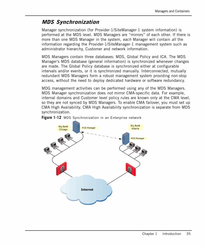
MDS SynchronizationManager synchronization (for Provider-1/SiteManager-1 system information) is performed at the MDS level. MDS Managers are “mirrors” of each other. If there is more than one MDS Manager in the system, each Manager will contain all the information regarding the Provider-1/SiteManager-1 management system such as administrator hierarchy, Customer and network information.
MDS Managers contain three databases: MDS, Global Policy and ICA. The MDS Manager’s MDS database (general information) is synchronized whenever changes are made. The Global Policy database is synchronized either at configurable intervals and/or events, or it is synchronized manually. Interconnected, mutually redundant MDS Managers form a robust management system providing non-stop access, without the need to deploy dedicated hardware or software redundancy.
MDG management activities can be performed using any of the MDS Managers. MDS Manager synchronization does not mirror CMA-specific data. For example, internal domains and Customer level policy rules are known only at the CMA level, so they are not synced by MDS Managers. To enable CMA failover, you must set up CMA High Availability. CMA High Availability synchronization is separate from MDS synchronization. Figure 1-12 MDS Synchronization in an Enterprise network

Log Managers
36
Log Managers
Multi-Domain Log ModuleThe Multi-Domain Log Module (MLM) is an optional server that is dedicated to log collection, separating critical management activities from logging traffic. It thereby provides the infrastructure for further data-mining activities and improves performance for large deployments by offloading log processing activities from the MDS. It is recommended for systems with many CMAs or a heavy logging load.
Redundant log infrastructures can be created by designating an MLM as a primary log server and the MDS as a backup. In the event that the MLM cannot be reached, logs are redirected to the MDS. It is possible to have multiple MLMs in the Provider-1/SiteManager-1 network. The MLM is controlled by the MDG, and maintains Customer Log Modules (CLMs), with a separate log repository for each Customer.
Let’s look at Big Bank. Big Bank is expanding and has opened a number of new branches. It has decided to track activity in its system to satisfy security requirements. It has created an environment with three MDS’s. The system administrators have set up an MDS Manager/Container with a second Container to manage VPN-1 Pro gateways throughout the different bank branches. They have also set up an MLM to track activity.Figure 1-13 A simple system with an internal MLM

Log Managers
Chapter 1 Introduction 37
Customer Log ModuleA Customer Log Module (CLM) is a log server for a single Customer. Service providers can deploy CLMs to monitor specific Customer modules. Enterprises may deploy CLMs to monitor branch activity.
In the example below, Big Bank uses a specific CLM to collect information about the Paris branch’s gateway activities. Figure 1-14 CLM gets activity data from customer’s VPN-1 Pro gateway

High Availability
38
High Availability
CMA High AvailabilityCMA High Availability is implemented by using two CMAs to manage one Customer network, one in Active mode, the other in Standby. Implementing management High Availability guarantees fail-over capability. At any given time, only one CMA is Active, while the Standby CMA is synchronized with the Active CMA.
Data synchronization between the two CMAs greatly improves fault tolerance and enables the administrator to seamlessly activate a Standby CMA when required. With High Availability, should a CMA fail for any reason, the Standby CMA can continue operation without service interruption.
The High Availability scheme requires one Primary CMA and one Secondary CMA, which are housed separately, on different MDS computers. Administrators make security policy changes through the Active CMA. If policy changes are made with the Active CMA, the Standby CMA can be set up to synchronize automatically to reflect these changes.
These CMAs must be synchronized in order to maintain the same information. It is possible to configure the High Availability feature to synchronize automatically for each policy installation operation, on each policy save operation and on any other scheduled event. If the Active CMA’s data has not be synchronized with the Standby CMA, you can still use the Standby CMA, which is updated until the moment of the last synchronization.

Security Policies in Provider-1
Chapter 1 Introduction 39
Security Policies in Provider-1Security Policies are created to enforce security rules. Administrators can create security policies and rules tailored to a specific Customer, or a type of Customer. In the Provider-1/SiteManager-1 environment, administrators create Customer security policies for a specific set of gateways, using the CMA, which is the equivalent of the SmartCenter server in the VPN-1 Pro model. To find out details about how the VPN-1 Pro works with security policies, see the VPN Guide and Firewall and SmartDefense Guide.
The Need for Global PoliciesBesides security policies for a specific set of gateways, administrators need to create policies which apply to the entire Provider-1/SiteManager-1 environment. The separation between different levels of policies, and different types of policies, means that Customer-level security rules do not need to be reproduced throughout the entire Provider-1/SiteManager-1 environment. Policies can be created and privately maintained for each Customer, ensuring a Customer’s security integrity. Global Policies enforce security for the entire Provider-1/SiteManager-1 system.

The Management Model
40
The Management ModelIn This Section
Introduction to the Management ModelIn the Provider-1/SiteManager-1 environment, the management model has been designed so that network security managers can centrally and securely manage many distributed systems. Network security is sharpened by differentiating between different levels of security needs, and differentiating between access privileges and needs. The Provider-1/SiteManager-1 management model allows you to designate trusted users (administrators) with different access rights. It enables trusted communication both within the Provider-1/SiteManager-1 network, and with customers’ network environments.
AdministratorsIt is important, for security purposes, that there be different types of administrative authority. Administrators with authority over the entire system are needed in order to manage the entire Provider-1/SiteManager-1 system. But there also must be a level of administration authority which only applies to the customer environment and not to the Provider-1/SiteManager-1 system.
It is inappropriate for an administrator who remotely manages a VPN-1 Pro gateway in a particular customer network to have authority over or access to the entire Provider-1/SiteManager-1 system. This could be a serious security breach, as a customer’s internal staff would have access to other customer networks. For example, it would not be appropriate for an MSP to allow an administrator of one of its customers to have the authority to shut down an MDS Manager or delete all the superusers from the system.
In the Provider-1/SiteManager-1 environment, four types of administrators have been designated to handle different levels of responsibility. While there is a need for administrators with the authority to create and manage the entire Provider-1/SiteManager-1 environment, not every administrator in the system has this level of complete control. The following table shows permissions by type of administrator.
Introduction to the Management Model page 40
Administrators page 40
Management Tools page 42

Administrators
Chapter 1 Introduction 41
Table 1-1 Administrator levels and their access permissions
Administrator Permissions
Provider-1 Superuser
Provider-1 Superusers manage the entire Provider-1/SiteManager-1 system and can oversee all the networks of all Customers in the Provider-1/SiteManager-1 system. They can use all MDG tools relating to Customer and MDS management, and can manage all other administrators. Provider-1 Superusers have sole permission to manage and change the MDSs. They can:
• Add, edit or delete MDSs, including manager servers, containers, High-Availability servers, logging servers, etc.
• Enable or disable a computer’s permission to access the MDG.
Customer Superuser
Customer Superusers can manage the networks of all Customers in the system, using the MDG and SmartConsole tools. They can use all MDG tools relating to Customer management; create, edit and delete Customers; and see all the network objects for all of the Customers. Customer Superusers can manage Customer Managers and None Administrators. However, they cannot manage or change the MDS environment or manage Provider-1 Superusers.
Customer Manager
Customer Managers manage their assigned set of Customers’ networks from within the Provider-1/SiteManager-1 environment, but have fewer permissions than Customer Superusers. They can:
• Access the General, Global Policies, High Availability and Connected Administrators Views.
• View and manage (add/edit/delete) their Customers’ network objects.
Customer Managers with Read/Write/All permissions can:• Edit their Customers.• Add, edit and delete their Customer's CMAs and CLMs.• Start or stop their Customer's CMAs and CLMs.• Import their Customer’s CMAs to another MDS.• Create None administrators for their customers.
None None administrators manage their Customers according to their assigned permissions. They are outside of the Provider-1/SiteManager-1 management environment. They manage their internal networks using the SmartConsole tools, e.g., SmartDashboard. They do not have access to the Provider-1/SiteManager-1 system, and cannot open an MDG.
Management Tools
42
Management Tools
In This Section
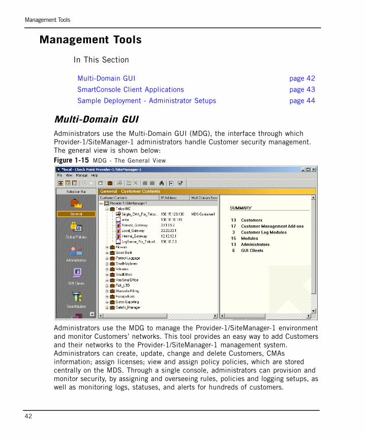
Multi-Domain GUIAdministrators use the Multi-Domain GUI (MDG), the interface through which Provider-1/SiteManager-1 administrators handle Customer security management. The general view is shown below:Figure 1-15 MDG - The General View
Administrators use the MDG to manage the Provider-1/SiteManager-1 environment and monitor Customers’ networks. This tool provides an easy way to add Customers and their networks to the Provider-1/SiteManager-1 management system. Administrators can create, update, change and delete Customers, CMAs information; assign licenses; view and assign policy policies, which are stored centrally on the MDS. Through a single console, administrators can provision and monitor security, by assigning and overseeing rules, policies and logging setups, as well as monitoring logs, statuses, and alerts for hundreds of customers.
Multi-Domain GUI page 42
SmartConsole Client Applications page 43
Sample Deployment - Administrator Setups page 44

Management Tools
Chapter 1 Introduction 43
The MDG also is used to create administrators of all four types and assign their permissions. The MDG can even be used to designate which other computers can be entrusted to run the MDG. Administrators can create a logging setup by adding an MLM (Log Containers) to the Provider-1/SiteManager-1 management system, and designating a dedicated customer’s server as a CLM for that customer. Further, it is possible to update Check Point software installed on all Provider-1/SiteManager-1 computers and Customer network computers using SmartUpdate, via the MDG.
From the MDG, an administrator can launch Global SmartDashboard to create Global Policies, or the administrator can launch SmartConsole Clients for each of the Customers. Outside of the Provider-1/SiteManager-1 environment, local administrators can also run SmartConsole Client applications for each of the Customers.
SmartConsole Client Applications SmartConsole Clients are the Check Point tools used to design, manage, monitor and log the firewall enforcement policies. SmartConsole Clients include all the following:
• SmartDashboard is used by the system administrator to define and manage the Security Policy. From this SmartConsole you can access many Check Point features and add-ons.
• SmartView Tracker is used for managing and tracking logs throughout the system.
• SmartUpdate is used to manage and maintain a license repository, as well as to facilitate upgrading Check Point software.
• SecureClient Packaging Tool is used to define user profiles for SecuRemote/SecureClient clients.
• SmartView Monitor is used to monitor and generate reports on traffic on interfaces, Provider-1/SiteManager-1 and QoS modules, as well as on other Check Point System counters. It is also is used for managing, viewing alerts and testing the status of various Check Point components throughout the system.
• Eventia Reporter is used to generate reports for different aspects of network activity.
• SmartLSM is used for managing large numbers of ROBO Gateways via the SmartCenter server or Provider-1/SiteManager-1 CMA.

Management Tools
44
Sample Deployment - Administrator SetupsLet’s examine a sample deployment, in which a service provider has an MDG console set up within the Provider-1/SiteManager-1 environment, and customers have their own consoles within their internal networks.
The service provider’s Provider-1 Superuser administrator, Rosa, uses the installation CD and command line utilities to configure and set up the entire Provider-1/SiteManager-1 environment. Then, she uses the MDG and the Global SmartDashboard to manage the global policies. As a Provider-1 Superuser, Rosa is responsible for everything to do with the physical layout of the service provider’s environment, and managing all the highest level security authorizations. Figure 1-16 Rosa sets up the Provider-1/SiteManager-1 environment
Rosa knows that her Provider-1/SiteManager-1 environment will run a large system, with hundreds of Customers, and it will not be possible for one administrator to handle all the activity. It is time to start considering staffing issues. Customer Superusers can handle all Customer specific management activities. They can create/delete/edit Customers and create edit or delete CMAs. Rosa authorizes Martin to be a Customer Superuser. Now Martin can add customers to the system.

Management Tools
Chapter 1 Introduction 45
Figure 1-17 Martin adds customers to the Provider-1/SiteManager-1 environment
Martin starts adding customers into the system. Each customer needs a security policy to monitor the customer network’s enforcement point, the VPN-1 Pro gateway. The work is really piling up! Now that the customer base is expanding, it is time for Martin, as a Customer Superuser, to add more customer administrators.
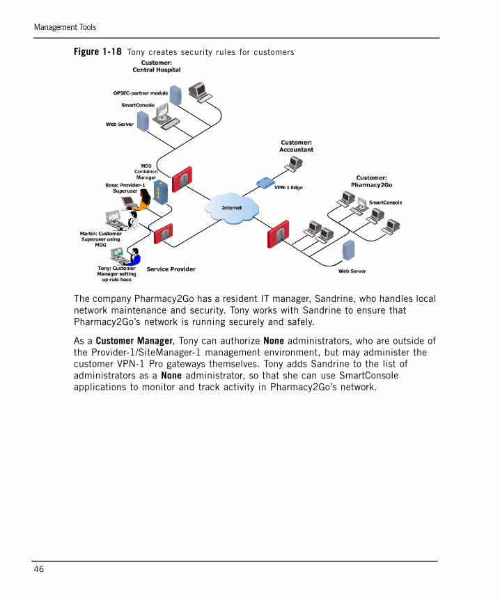
Martin authorizes Tony to be a Customer Manager for the customers Accountant and Pharmacy2Go. Customer Managers can handle many Customer specific management activities. They can add, edit or delete their Customer’s CMAs. They can start or stop their Customer's CMAs and CLMs. They can also import their Customer’s CMAs to another server, and create customer security rules. It’s time for Tony to create security policies for Pharmacy2Go and for Accountant.
Management Tools
46
Figure 1-18 Tony creates security rules for customers
The company Pharmacy2Go has a resident IT manager, Sandrine, who handles local network maintenance and security. Tony works with Sandrine to ensure that Pharmacy2Go’s network is running securely and safely.
As a Customer Manager, Tony can authorize None administrators, who are outside of the Provider-1/SiteManager-1 management environment, but may administer the customer VPN-1 Pro gateways themselves. Tony adds Sandrine to the list of administrators as a None administrator, so that she can use SmartConsole applications to monitor and track activity in Pharmacy2Go’s network.

Management Tools
Chapter 1 Introduction 47
Figure 1-19 Sandrine works with SmartConsole Clients
Sandrine can run SmartConsole Client applications for Pharmacy2Go’s network, now that she has been made a None administrator. Remember, None administrators manage their own internal networks via the CMA. They do not have access to other elements in the Provider-1/SiteManager-1 environment.
Notice that the Provider-1/SiteManager-1 network itself needs to maintain its own security, protecting the confidentially of critical information regarding customer networks, administrators, and access details, as well as for its own network! It can use a stand-alone VPN-1 Pro gateway, or define a CMA to manage its gateway. If the gateway is standalone, Rosa can manage it through its own SmartCenter server. If maintained by the MDS, it is managed with a CMA.

The Provider-1/SiteManager-1 Trust Model
48
The Provider-1/SiteManager-1 Trust ModelIn This Section
Introduction to the Trust ModelThe Provider-1/SiteManager-1 system provides a method for MDSs and CMAs to establish secure, trusted and private communication between Check Point modules while ensuring data integrity. This is a critical component in ensuring that system management commands and system information are delivered securely.
Provider-1/SiteManager-1 systems must establish safe process communication between MDSs, between MDSs and CMAs, between CMAs and the Customers’ Modules that they are managing, and between administrators and CMAs. To ensure secure and private communication, Secure Internal Communication is used.
Secure Internal Communication (SIC)Secure Internal Communication (SIC) is used to establish trust between each of the computers and components in the Provider-1/SiteManager-1 system that must communicate with each other. A basic explanation of how SIC works appears in the SmartCenter Guide.
Safe communication ensures that the system can receive all the necessary information it needs to run correctly. Although information must be allowed to pass freely, it also has to pass securely. This means that all communication must be encrypted so that an imposter cannot send, receive or intercept communication
Introduction to the Trust Model page 48
Secure Internal Communication (SIC) page 48
Trust Between a CMA and its Customer Network page 49
Trust Between a CLM and its Customer Network page 50
MDS Communication with CMAs page 51
Trust Between MDS to MDS page 51
Authenticating the Administrator page 51
Authenticating via External Authentication Servers page 52
Re-authenticating when using SmartConsole Clients page 55
CPMI Protocol page 57

Trust Between a CMA and its Customer Network
Chapter 1 Introduction 49
meant for someone else, be authenticated, so there can be no doubt as to the identity of the communicating peers, and have data integrity, not have been altered or distorted in any way. Of course, it is helpful if it is also user-friendly.
The SIC model incorporates PKI. Certificates are issued to trusted communicating parties by an Internal Certificate Authority. These certificates are then used to authenticate every communication established between the communicating parties.
The following security measures are taken to ensure the safety of SIC:
• Certificates for authentication.
• Standards-based SSL for the creation of the secure channel.
• 3DES for encryption.
Trust Between a CMA and its Customer NetworkIn order to ensure authenticated communication between the Provider-1/SiteManager-1 environment and the Customer network environment, each CMA also has its own Internal Certificate Authority (ICA), which is responsible for issuing certificates to the CMA’s Customer gateways. The CMA ICA is part of the CMA data residing in the MDS Container. Each CMA ICA is associated with a specific Customer. A Customer’s secondary CMA shares the same Internal Certificate Authority as the primary CMA.
The ICA of each CMA issues a certificate to the VPN-1 Pro gateway(s) in the Customer’s network. SIC can then be established between the CMA and each of its Customer’s VPN-1 Pro gateways.
Different CMAs have different ICAs to ensure that a CMA establishes secure communication with its own Customer’s gateways, but that different Customer CMAs cannot penetrate each other’s internal networks and establish communication with another Customer’s gateways.

Trust Between a CLM and its Customer Network
50
Figure 1-20 SIC between CMA and Customer gateway
Trust Between a CLM and its Customer NetworkThe CLM (Customer Log Manager) also receives a certificate from the CMA’s ICA. This is so that the Customer’s VPN-1 Pro gateways can establish communication with the CLM, for tracking and logging purposes. The gateways and CLM must be able to trust their communication with each other, but only if they belong to the same customer. Otherwise, different customers could monitor each other, which would be a security breach.

MDS Communication with CMAs
Chapter 1 Introduction 51
MDS Communication with CMAsEvery MDS Container communicates with the CMAs that it houses locally and securely through a protocol called SIC local. This type of authentication, SIC local, is managed by the Provider-1/SiteManger-1 environment and allows internal MDS communication to be trusted.
SIC is used for remote (not on the same host) communication, whereas SIC local is used for a host’s internal communication. SIC local communication does not make use of certificates.
Trust Between MDS to MDS The primary MDS Manager, the first Manager created, has its own Internal Certificate Authority. This ICA issues certificates to all other MDSs, so that trusted communication can be authenticated and secure between MDSs. All MDSs share one Internal Certificate Authority. Figure 1-21 SIC between MDSs
The ICA creates certificates for all other MDSs, and for Provider-1/SiteManager-1 administrators. Administrators also need to establish trusted communication with the MDSs.
Authenticating the AdministratorAdministrators are authenticated to access the MDS via the MDG either by using a User Name and Password combination (which is considered only semi-secure) or by using a certificate issued by the MDS ICA (far more secure).

Authenticating via External Authentication Servers
52
Figure 1-22 SIC between Administrator and MDS
For management purposes, administrators use the certificates provided by the MDS ICA to establish trusted communication to manage the CMAs. This is because every CMA also trusts the MDS ICA for administrator management activities using a communication medium, CPMI. This means that administrators do not need to have certificates issued to them for every CMA that they communicate with. Figure 1-23 SIC between administrators and a customer CMA
Authenticating via External Authentication ServersProvider-1/SiteManager-1 supports authentication using an external server that contains a database of users’ login information (for example, username, password and attributes). When a Provider-1/SiteManager-1 administrator is set to authenticate using one of these external servers, all authentication requests are forwarded to the authentication server. The external server authenticates and authorizes the user and sends a reply to the MDS. Only if the administrator is authenticated and verified will the MDS allow the administrator to connect to the MDS or the CMA.
Provider-1/SiteManager-1 supports the following external authentication servers for administrators when logging into MDS and CMA:
Authenticating via External Authentication Servers
Chapter 1 Introduction 53
• RADIUS
Originally developed by Livingston Enterprises (now part of Lucent Technologies) in 1992, Remote Authentication Dial-In User Service (RADIUS) is an external authentication scheme that provides security and scalability by separating the authentication function from the access server. The RADIUS protocol uses UDP to communicate with the MDS. RADIUS was submitted to the Internet Engineering Task Force (IETF) as a proposed standard protocol in 1996. RFC 2865 is the latest update to the proposed standard, and can be found at the URL www.ietf.org/rfc/rfc2865.txt.
• TACACS
Terminal Access Controller Access Control System (TACACS) provides access control for routers, network access servers and other networked devices via one or more centralized servers. TACACS was originally developed by the U.S. Department of Defense and BBN Planet Corp. and then further developed by Cisco. A newer version of the protocol called TACACS+ provides enhancements to the original protocol, including the use of TCP instead of UDP.
The system supports physical card key devices or token cards, and supports Kerberos secret-key authentication. TACACS encrypts the username, password, authentication services and accounting information of all authentication requests for more secure communications.
• RSA SecurID ACE/Server
Developed by RSA Security, SecurID requires users to both possess a token authenticator and to supply a PIN or password. Token authenticators generate one-time passwords that are synchronized to an RSA ACE/Server, and may come in the form of hardware or software. Hardware tokens are key-ring or credit card-sized devices, while software tokens reside on the PC or device from which the user wants to authenticate. All tokens generate a random, one-time-use access code that changes every minute or so. When a user attempts to authenticate to a protected resource, that one-time-use code must be validated by the ACE/Server.
The following diagram depicts an authentication process in which administrators use external authentication:

Setting up External Authentication
54
Figure 1-24 Authentication using an External Authentication Server
TACACS and RADIUS authentication methods, when authenticating an administrator connecting to a CMA, use the MDS as a proxy between the CMA and the external authentication server. Therefore, each MDS container should be defined on the authentication server, and the authentication server should be defined in the global database. In addition, if the MDS is down, the CMA will not be able to authenticate administrators.
Setting up External AuthenticationTo authenticate using an authentication server, the MDS must know which administrators should be authenticated. Administrator authentication is performed through the MDG as follows:
1. Open MDG > Administrators.
2. Create a new administrator.
3. In the General tab enter the same user name that was created on the authentication server.
4. Mark the administrator’s permission.
5. On the Authentication tab, select the Authentication Scheme. If using RADIUS or TACACS, choose the appropriate server that was configured in Global SmartDashboard.
6. If using SecureID, do the following:

Re-authenticating when using SmartConsole Clients
Chapter 1 Introduction 55
1. Generate the file sdconf.rec on the ACE/Server, and configure the user to use Tokencode only.
2. Copy sdconf.rec to /var/ace/ on each MDS.
3. Edit the file /etc/services and add the following lines:
• securid 5500/udp
• securidprop 5510/tcp
4. Reboot the MDS machines.
Alternatively, instructions 3., 4. and 5. can be performed from the command line interface (CLI), with the following syntax:
Re-authenticating when using SmartConsole Clients
When a SmartConsole Client is launched from another open SmartConsole Client, the system by default reapplies the credentials entered when the administrator logged into the first Client.
However, there are cases where it is useful to compel administrators to re-authenticate for each SmartConsole Client they launch. When using RSA SecurID to authenticate Provider-1/SiteManager-1 administrators, for instance, it is common to require re-authentication when SmartConsole Clients connect to MDSs or CMAs.
You can compel administrators to re-authenticate every time a new GUI client is launched and connects to:
• a specific CMA
• all CMAs created on this system in the future
• this MDS or MLM
The instructions for each are listed below.
mdscmd setadminauth <administrator name>
<undefined | os | fw1 | securid | tacacs | radius> [authenticationserver name]
[-m mds -u user -p password]

Re-authenticating when using SmartConsole Clients
56
...When Connecting to a Specific CMAThe following commands need to be executed in a root shell on the MDS machine hosting the CMA:
dbedit -s <IP of the CMA> -u <name of the administrator with edit permissions for this CMA> -p <password of the administrator>
modify properties firewall_properties fwm_ticket_ttl 0
update properties firewall_properties
quit
If the relevant Customer has more than one CMA, synchronize the CMAs for the change to take effect on both. If the Customer owns one or more CLMs, the Install Database operation should be performed on each CLM for the change to take effect.
...When Connecting to all CMAs Created on This System in the FutureThe following steps need to be executed in a root shell of every MDS Container machine:
Run the command mdsenv.
Edit the file $MDS_TEMPLATE/conf/objects_5_0.C
Find the line containing :fwm_ticket_ttl
Replace it with the line :fwm_ticket_ttl (0)
...When Connecting to this MDS or MLMThe following commands need to be executed in a root shell on the MDS machine hosting the CMA:
dbedit -s <IP of the MDS or MLM> -u <name of the administrator with edit permissions for the Global Policy of the MDS> -p <password of the administrator>
modify properties firewall_properties fwm_ticket_ttl 0
update properties firewall_properties
quit
If the Provider-1/SiteManager-1 configuration consists of more than one MDS Container server or MLM, synchronize the Global Policy for the change to take effect on all MDS Container servers or MLMs.

CPMI Protocol
Chapter 1 Introduction 57
CPMI ProtocolThe CPMI (Check Point Management Interface) protocol is a generic open protocol that allows third party vendors to interoperate with Check Point management products. The client side of CPMI is included in the OPSEC SDK documentation, so third-party products can integrate with the CMAs. For more information on CPMI, see the CPMI guide in the OPSEC SDK documentation.

CPMI Protocol
58

59
Chapter 2Planning the Provider-1 Environment
In This Chapter
This chapter deals with different aspects required in order to plan and prepare for setting a first time deployment with Provider-1. In every first time setup there are general questions that you need to ask yourself, such as
• What do you need to know about the basic components that need to be installed?
• How should the basic components be deployed and in what order should they be installed?
• What are the hardware requirements that need to be considered?
• What licenses need to be obtained in order to run the product?
Asking yourself the right questions... page 61
Consider the Following Scenario... page 63
Protecting the Provider-1/SiteManager-1 Network page 65
MDS Managers and Containers page 66
Setting up the Provider-1/SiteManager-1 Environment page 69
Hardware Requirements and Recommendations page 74
Provider-1/SiteManager-1 Order of Installation page 75
Licensing and Deployment page 76
Miscellaneous Issues page 82

60
• What are other additional requirements that may influence the performance, strength or security of the environment?
In this chapter, we will deal with many of the questions that you need to consider when planning your Provider-1/SiteManager-1 environment.

Asking yourself the right questions...
Chapter 2 Planning the Provider-1 Environment 61
Asking yourself the right questions...There are many things that need to be considered when deciding how to deploy your Provider-1/SiteManager-1 environment, this section talks very generally about some of the issues. Specific details are discussed at a later stage.
Safety comes first
Whatever deployment you choose to implement needs to safeguard and protect your networks. You will need to install an enforcement module to protect Provider-1/SiteManager-1 environment. For more information see, “Protecting the Provider-1/SiteManager-1 Network” on page 65
MDS Managers & Containers - How Many Do You Need?
Every Provider-1/SiteManager-1 management network requires at least one MDS Manager (where Provider-1/SiteManager-1 system information is stored and MDG clients can connect to it to monitor and control the Provider-1/SiteManager-1 system), and one MDS Container (where CMA/CLM data is stored per Customer.) and more important, The MDS Manager and MDS Container can be installed together on one computer.
Take note that the greater your Customer base the more Containers will be necessary in the system to support the database load for these Customers. For more information, see “MDS Managers and Containers” on page 66.
Choosing The Right Environment
Choose the deployment that best suits your need, amongst the options you can deploy a standalone or a distributed environment. For more information, see “Setting up the Provider-1/SiteManager-1 Environment” on page 69.
Choosing The Right Platform
• When choosing between a Linux, Solaris or Check Point SecurePlatform Operating System/platform, remember that all the MDSs in the system must all be of the same platform.
• The Provider-1/ SiteManager-1 management console, the MDG, can run in both Windows and Solaris environments.
High Availability
If you are supporting many complex Customer networks, you may decide to implement failover/ recovery capabilities:

Asking yourself the right questions...
62
• For CMA High Availability, you need to have at least two Containers. By creating two containers, you will be able to create two CMAs for each Customer. The CMAs will serve as Active and Standby Management servers for the Customer's Enforcement points.
• For MDS High Availability, where there is multiple entry points to the system, you should also have at least two Managers in order to allow you to connect to the system with the MDG even when one of the Managers is not available.
Logging & Tracking
If you decide to implement logging for tracking and troubleshooting purposes, for a very large system where many different services and activities are being tracked, it is recommended that you have one or more dedicated log servers (MLM).
Migrating In A Standalone Environment
If you want to migrate standalone SmartCenter server management components into Provider-1/SiteManager-1 CMAs, ensure that you are thoroughly acquainted with the procedure. Before you begin consult the Upgrade Guide choose a method and ensure a setup that supports your migration strategy.
Routing Issues In A Distributed Environment
If you have a distributed system, with MDS servers located remotely, ensure that you have considered routing issues. Routing must enable all MDS components of the Provider-1/SiteManager-1 system to communicate with each other, and for CMAs to communicate with Customer networks. For more information, see “IP Allocation & Routing” on page 82.
Platform & Performance Issues
Check Provider-1/SiteManager-1 system hardware and platform requirements, and ensure that you have the needed platform patches installed. If you have an MDS with multiple interfaces, ensure that the total load for each MDS computer conforms to performance load recommendations. For more information see, “Hardware Requirements and Recommendations” on page 74.
Setting Up Administrators
Consider which computers administrators will manage the system, and the administration hierarchy that you want to establish.
Setting Up Licenses
Once you have determined what sort of server/computer configuration you need, you will want to ensure that you have the appropriate licenses. For more information, see “Licensing and Deployment” on page 76.

Consider the Following Scenario...
Chapter 2 Planning the Provider-1 Environment 63
Consider the Following Scenario...The following scenario outlines a typical example of the basic components and features that can be implemented that need to be taken into consideration when planning.
Environment: Distributed with High Availability
Consider the following: a medical supplies firm has several branch locations, and requires failover capabilities. MDSs are installed in three branches: Kansas, Osaka, and Montenegro. Each MDS has a mix of primary and secondary CMAs.
Security: VPN-1 Pro module
Critical to comprehensive security, each MDS is protected by a VPN-1 Pro module. This enforcement module should be managed by a CMA or by a standalone SmartCenter server.
The gateway on which the enforcement module is installed must have a security policy that adequately protects the network and which allows secure communication between Provider-1/SiteManager-1 components and external customer networks.
The enforcement module must have security rules that allow CMAs to communicate with customer gateways, and that allow external customer administrators to access CMAs. Figure 2-1 CMA High Availability in an Enterprise network
Requirement: Logging and Tracking
Consider the Following Scenario...
64
Most enterprise systems and MSPs require event logging and tracking. Accountability requirements can lead to sizeable log maintenance. By default, logs will be stored on the Customer’s CMA that manages the module which is generating the logs in the Provider-1/SiteManager-1 management network. For most systems, in terms of licensing, it is more cost-effective to dedicate an MLM server to store logs rather than purchase extra Managers for this purpose. It is recommended that you implement one or more dedicated log servers (MLMs), depending on the activity tracking load in the system Provider-1/SiteManager-1 manages.
For more information about logging, see Chapter 7, “Logging in Provider-1”.
Requirement: GUI Clients & their Platforms
Finally, consider the platforms that will be used to run the GUI tools used to manage the Provider-1/SiteManager-1 and Customer environments. The Provider-1/SiteManager-1 system is monitored using the MDG and SmartConsole Client applications. GUI Clients should be deployed either inside or outside of the Provider-1/SiteManager-1 network to enable administrators to access the Provider-1/SiteManager-1 system. The MDG runs on either Solaris and Windows platforms; the platform does not have to match the MDS’s platform.
Requirement: Routing & Communication
If GUI Clients are located outside of the Provider-1/SiteManager-1 network, communication between these computers and the MDS Manager(s) must be allowed. If MDSs are in different remote locations, and there is more than one Provider-1/SiteManager-1 network, communication between the remote MDSs and the local MDSs must be allowed. Also ensure appropriate routing to support communication between computers and servers.

Protecting the Provider-1/SiteManager-1 Network
Chapter 2 Planning the Provider-1 Environment 65
Protecting the Provider-1/SiteManager-1 Network
No matter how Provider-1/SiteManager-1 management networks are setup and deployed, each management network must be protected. Each network must have firewall protection and an enforcement module must be setup for this purpose. This enforcement module should be managed by a CMA or by a standalone SmartCenter server.
The gateway on which the enforcement module is installed must have a security policy that adequately protects the network and which allows secure communication between Provider-1/SiteManager-1 components and external customer networks.
This enforcement module must ensure continued open communication between all the components, enabling MDSs to communicate with each other, and management servers (CMAs, CLMs, CMA-HAs) to communicate with customer networks. It must support proper routing. At the same time while the lines of communication must be open and free, they must also be secure.
The enforcement module must have security rules that allow CMAs to communicate with customer gateways, and that allow external customer administrators to access CMAs.

MDS Managers and Containers
66
MDS Managers and ContainersEvery Provider-1/SiteManager-1 environment requires at least one MDS Manager and one MDS Container. Beyond the minimum requirements, to determine how many MDSs your environment requires, consider the functionality of the different types of MDSs.
In This Section
MDS ManagersUse the MDG to connect to the MDS Managers in order to monitor and control the Provider-1/SiteManager-1 environment. If more than one MDS Manager is deployed:
• They can provide mutually redundant fail-over capabilities.
• They can be configured to synchronize global policy data either automatically or manually.
MDS ContainersMDS Containers contain and manage Customer data such as the Customer’s network objects’ database and security policies, This data is private (per Customer) and therefore it is not shared. Consider the following:
• “MDS Containers and High Availability” on page 66
• “MDS Containers and Performance Issues” on page 67
MDS Containers and High AvailabilityCustomer data can only be maintained in a redundancy scenario, that is, if High Availability has been enabled for the Customer. This is called CMA-High Availability, or CMA-HA. Data sharing is on a Customer by Customer basis, and is synchronized between the CMA and CMA-HA. At least two Containers are required for CMA High Availability because the Customer’s CMA-HA must be set up on a
MDS Managers page 66
MDS Containers page 66
Choosing your deployment for MDS Managers and Containers page 67
MDS Clock Synchronization page 68

Choosing your deployment for MDS Managers and Containers
Chapter 2 Planning the Provider-1 Environment 67
different Container than the CMA (see Chapter 10, “High Availability”). The Customer's Primary CMA should reside on one Container and the Secondary CMA should reside on the other.
MDS Containers and Performance IssuesThe Container load depends on the complexity of the Customer’s policies and setups. Multiple Containers can cascade to manage thousands of CMAs in a single environment. In general, to support numerous Customers who have complex networks, it is advisable to deploy several Containers, since, a Container with an overload of CMAs can suffer performance-wise.
Choosing your deployment for MDS Managers and Containers
You can set up your MDS Managers and Containers in Mirror Sites, or in a Distributed Environment.
Setting up MDS Managers and Containers in Mirror SitesService provider usually need a robust system with many Containers to handle the large amount of data and rules used to manage their customers’ networks. An MSP may implement a remote mirror site for disaster recovery. For example, an MSP can create a Provider-1/SiteManager-1 management network containing a Manager, with several Containers housing Customers’ CMAs. The MSP can also maintain a mirror site in another city, comprising of a secondary Manager, with several Containers storing CMA-HAs.
MDS Managers and Containers in a Distributed EnvironmentAn enterprise system can centralize the Provider-1/SiteManager-1 management network at one branch yet have one or more backup MDSs at other locations. (For more information about fail-over options, see Chapter 10, “High Availability”.)
For example, a corporate bank with several international branches locates the “primary” Provider-1/SiteManager-1 management network in their headquarters. But, to support Active CMAs for the different local branches, they maintain an MDS Container per region, at a central regional branch. The CMA-HAs can be maintained for fail-over capabilities in the Provider-1/SiteManager-1 management network

MDS Clock Synchronization
68
MDSs in the headquarters, or distributed to the local MDS Containers. If a central regional branch contains an MDS Manager as well, the whole MDS environment can be accessed by connecting the MDG GUI client to that server.Figure 2-2 CMA High Availability in an Enterprise network
MDS Clock SynchronizationFor MDSs to be able to properly synchronize, all MDSs’ system clocks must be synchronized. If there is more than one MDS computer in the system, before installing any new MDS, first synchronize the computer clock with other MDSs in the system.
The time of modification is written using UTC (Coordinated Universal Time), used by MDSs’ system clocks. Synchronize MDS clocks using any synchronization utility. It is recommended that you reset regularly to compensate for clock drift. Correct database operation requires that the MDS clocks are synchronized to the second. It is recommended that MDS clocks be synchronized automatically at least once a day.

Setting up the Provider-1/SiteManager-1 Environment
Chapter 2 Planning the Provider-1 Environment 69
Setting up the Provider-1/SiteManager-1 Environment
The Provider-1/SiteManager-1 topology depends on system and business requirements. A number of simplified basic scenarios for enterprises are discussed in this section. Provider-1/SiteManager-1 is designed to flexibly support many different types of management network and customer network configurations. These include:
• “A Typical Scenario” on page 69
• “A Standalone Provider-1/SiteManager-1 Network” on page 70
• “A Distributed Provider-1/SiteManager-1 Network” on page 71
• “Provider-1/SiteManager-1 Network with Point of Presence (POP) Center” on page 72
A Typical ScenarioEnterprises usually choose to put the Provider-1/SiteManager-1 management network in its own segment, separated from the main enterprise network by an enforcement module. Figure 2-3 Separate and protect network segments

A Standalone Provider-1/SiteManager-1 Network
70
Provider-1/SiteManager-1 servers are often separated from support servers such as Radius, LDAP, and anti-virus servers. This is not by any means a requirement. Figure 2-4 Separate support segments
A Standalone Provider-1/SiteManager-1 NetworkThe Provider-1/SiteManager-1 management system can be set up in one network location, with all the MDSs located in the same local network. Fail-over capabilities are enabled by having at least two Manager/Container MDSs. Management and maintenance is centralized through the Provider-1/SiteManager-1 network segment. The advantage of this setup is that routing complexity is considerably reduced.
Logs can be stored centrally on the MLM server (per Customer in different CLMs) and accessed via SmartView Tracker.

A Distributed Provider-1/SiteManager-1 Network
Chapter 2 Planning the Provider-1 Environment 71
Figure 2-5 Separate Provider-1/SiteManager-1 segment with remote logging
A Distributed Provider-1/SiteManager-1 NetworkThe Provider-1/SiteManager-1 management system can be distributed over different geographical locations to provide disaster recovery capabilities and to minimize the overhead of logging traffic. In such a deployment, MDS managers and containers exist on both the local network and other remote networks. An MLM may also be set up at a remote location as a way of “outsourcing” logging traffic. Routing must ensure that local and remote MDSs can communicate with each other to maintain MDS synchronization. Each Provider-1/SiteManager-1 network segment must have adequate protection, by a VPN-1 Pro enforcement module.

Provider-1/SiteManager-1 Network with Point of Presence (POP) Center
72
Figure 2-6 Separate Provider-1/SiteManager-1 segments for disaster recovery/logging
Provider-1/SiteManager-1 Network with Point of Presence (POP) Center
Provider-1/SiteManager-1 can be configured to manage a POP center which allows branch offices to receive service and secured Internet access via leased lines to the POP service center. All Provider-1/SiteManager-1 components, such as the MDS and the MDG (the management console), are located in one network locations. Customers or corporate users dial-in to receive services, and connect to the Internet via the POP center.
Usage is monitored and protected via the Provider-1/SiteManager-1 management network, and branches do not have to be involved in any of the security management. All aspects of security and access are completely maintained using CMAs on the MDS to manage the enforcement point in the POP center. The CMAs in the MDS do this by managing the security policies for the VPN-1 Pro gateways in the POP center.

Provider-1/SiteManager-1 Network with Point of Presence (POP) Center
Chapter 2 Planning the Provider-1 Environment 73
Figure 2-7 A simple model of a POP configuration

Hardware Requirements and Recommendations
74
Hardware Requirements and Recommendations
The Provider-1/SiteManager-1 disk space requirements are as follows:
• For basic MDS installation: 800MB.
• For each CMA: 50MB for the CMA directory.
When considering disk space, it is recommended to use volume management software.

Provider-1/SiteManager-1 Order of Installation
Chapter 2 Planning the Provider-1 Environment 75
Provider-1/SiteManager-1 Order of Installation
For each MDS component’s setup to be stable and workable, it is important to conduct setup/installation in the following order:
1. Install the Operating System (OS).
2. Conduct OS hardening. It is advisable to remove unnecessary applications, scripts or libraries that are not needed as they are not necessarily secure. It is advisable to limit resident libraries and applications to those needed for system functionality.
3. Install the OS patches.
4. Install Check Point products.
5. Install Check Point patches.
6. Install Check Point hotfixes.
The appropriate OS patches, and the Provider-1/SiteManager-1 installation procedure is discussed in Chapter 3, “Provisioning the Provider-1 Environment”.

Licensing and Deployment
76
Licensing and Deployment
The Trial PeriodAll purchased Check Point products have a 15 day trial period. During this period the software is fully functional and all features are available without a license. After that period, a permanent license must be installed in order to continue using the software. Alternatively, an evaluation license must be obtained.
The starting point of this trial period is defined differently for different products. The Provider-1/SiteManager-1 trial period begins as soon as the MDS is installed (regardless of its type). The trial license is for an MDS Manager maintaining up to 200 CMAs. Each CMA you create during the trial period receives its own trial license for a Primary CMA managing an unlimited number of gateways. The license supports the Check Point SmartUpdate & SmartMap features and expires on the same day as the MDS’s trial license.
Considerations
Provider-1/SiteManager-1 Components Installed at the NOCThe following components are deployed at the Network Operation Center:
• Multi Domain GUIs (MDG)
• Multi Domain Servers (MDS), including Multi Customer Log Modules (MLM)
• Customer Management Add-on (CMA)
• Customer Log Module (CLM)
Selecting MDS and CMA LicensesSimilar MDS components must be installed on different computers. Two Managers cannot share the same computer. Each Container must also be on a separate computer. However, a Manager/Container combination can be housed on the same computer. Licenses are available separately or combined for the MDS components.
When considering which licenses to buy, a second MDS Manager is recommended for disaster recovery. A standalone MDS Manager is available to be used for management purposes only, serving as an entry point to the system.

Considerations
Chapter 2 Planning the Provider-1 Environment 77
If many CMAs will be supported by the system, or if the CMA load increases, more MDS Containers are needed, not Managers. CMAs are maintained only on Containers. Licenses for MLMs (dedicated log servers) are inexpensive, so they are a cost effective alternative to storing logs by default on Managers/Containers.
The MDS license is per IP, and is based on the following factors:
• The MDS type, whether Manager, Container, combined, or Log Manager (MLM).
• For Containers, the MDS license depends on the number of CMA managed.
Provider-1/SiteManager-1’s licensing is geared to match its scalable architecture. Licenses are matched to needs, and can be purchased to accommodate a growing Customer base. Components are licensed according to the number of CMAs and VPN-1 Pro modules. New CMAs can be seamlessly integrated, by upgrading to a larger license.
Each CMA requires its own CMA-level license. These are obtained per CMA’s IP address. The exceptions to this are the VSX Bundle license (see “VSX Bundle License” on page 79). Pro Add-ons for multiple CMAs are purchased in a bundled product, called Pro Add-ons for MDS. The way to generate the CMA Pro Add-on licenses in UserCenter is as follows: Perform the "Activate License" operation on the bundled product, using the IP address of the first CMA, to generate the license for this CMA. For each additional CMA, perform the "Change IP" operation on the bundled product, and change to the IP address of this CMA.
Install the generated licenses at the respective CMA level.
The MLM license is comprehensive so there is no need for separate licenses per CLM. A single license installed on the MLM applies to both the MLM and the CLMs it maintains. CLMs are per Customer and can receive logs from all of the Customer’s modules, regardless of their number. The number of modules that report to the same MLM is unlimited.
The MDG does not require a license.
Provider-1/SiteManager-1 Enterprise EditionProvider-1/SiteManager-1 supports the new licenses for Provider-1/SiteManager-1 Enterprise Edition Products. The new licenses enable an MDS with 3 or 5 CMAs (depends on the license purchased). Each CMA has a Pro license level and can manage an unlimited number of gateways.

Further Licensing Detail
78
Managing LicensesProvider-1/SiteManager-1 uses SmartUpdate to incorporate newer versions and licenses. Required components and licenses can easily be upgraded using the SmartUpdate view in the MDG.
Licenses are additive. For example, an MDS Container license for 50 CMAs and an MDS Container license for 25 CMAs add up to 75 hosted CMAs.
Further Licensing Detail
Licensing the Multi-Domain Server (MDS) There are two basic MDS components: Containers and Manager. Containers hold CMAs, whereas Managers manage the Provider-1/SiteManager-1 environment and provide entry points for the MDG GUI Clients.
SiteManager-1 LicensesThe SiteManager-1 MDS is a low cost MDS, whose CMAs are limited to managing specific modules. SiteManager-1 supports two license schemes:
1. Backwards compatibility license scheme. In this license scheme, each SiteManager-1 CMA manages only one module. The license is installed only at the MDS level: no local CMA licenses are required.
2. Small Office module for 250 protected nodes. In this license scheme, each CMA can manage only Small Office modules or modules protecting 250 hosts.
Multi-Customer Log Module (MLM) LicensesAn MLM is installed as a Container. In order to simplify the deployment process, a single license installed on the MLM applies to both the MLM and the CLMs it maintains. A customer’s CLM can receive logs from all of the customer’s modules, regardless of how many there are. See Chapter 7, “Logging in Provider-1”, for more details.
Customer Management Add-on (CMA) LicensesThe CMA is a Check Point SmartCenter Server. Each CMA manages a single customer’s network and requires a dedicated CMA license. While each CMA belongs to a single Customer, each Customer can have up to two CMAs, for High Availability purposes. These two CMAs must be maintained on different MDSs.

Further Licensing Detail
Chapter 2 Planning the Provider-1 Environment 79
CMAs are licensed according to the number of modules they manage. There are four levels of CMA licenses to enable scalable, cost effective deployment:
• CMA-1 — suitable for a Customer with one module.
• CMA-2 — suitable for a Customer with up to two modules.
• CMA-4 — suitable for a Customer with up to four modules.
• CMA-U — suitable for a Customer with an unlimited number of modules.
You do not have to install additional software when you create a CMA in the Provider-1/SiteManager-1 network. To add a new CMA, you only need add the CMA’s license, which is ordered per CMA IP. The number of QoS enforcement modules managed by a CMA is unlimited and requires no special license.
The CMA manages any of the following:
• VPN-1 Pro Modules versions NG and NGX on a variety of platforms (Solaris, Linux, Nokia, AIX, HP, NT, Win2K)
• VPN-1 Express Modules
• VPN-1 Edge Modules
• Bay Networks Devices
Customer Log Module (CLM) LicensesIf you want to host a CLM on a non-MLM MDS, you must install a CLM license. There is no limit to the number of CLMs that can be defined for a single Provider-1/SiteManager-1 Customer (as opposed to the number of CMAs, which is limited to two); however, each CLM must be created on a separate MDS.
Module LicensesA Customer’s modules require licenses. Modules are licensed according to the number of nodes at a site. A node is any computing device with an IP address connected to the protected network.
Provider-1/SiteManager-1 also supports Quality of Service (QoS) modules.
VSX Bundle LicenseThe VSX Bundle License provides licensing for managing VSs and CMAs, located on an MDS server. The bundle license is installed on the MDS server and permits a specific number of VSs to be managed. The number of CMAs that can be defined

Further Licensing Detail
80
on an MDS equals the number of VSs permitted plus one. The additional CMA is used for the CMA with VSX Box. The VSX bundle, however, does not limit the number of VSXs or VRs.
CMAs without a CMA-level license use the bundle license. If a CMA-level license is installed on a specific CMA to allow the management of a regular gateway, then that CMA stops using the bundle license, and the VSs located on it are not counted off the bundle license. When a CMA is managing a non-VSX module, both a CMA-level license and container license on the MDS is required.
VSX Bundle License for HA CMAsThe VSX HA CMA Bundle License is used for HA CMAs on a primary or backup MDS for High Availability. HA CMAs can use the regular bundle, but Primary CMAs cannot use the HA bundle.
License ViolationsWhen a license violation is detected, syslog messages are sent, pop-up alerts in the MDG, and audit entries in the SmartView Tracker stating the nature of the violation, are generated. In addition, an indication about the license violation appears on the status bar of the MDG.
While the MDS is in violation, new CMAs, VSXs, VSs or VRs cannot be added to the MDS.
Replacing the Trial Period LicenseAfter the trial period expires, a permanent license must be installed. Before installing a new license, make sure the amount of CMAs and VSs do not exceed the amount permitted by the new license. Installing a new license that allows less CMAs or VSs than were configured during the trial period is a violation. As a result, the MDS will not start.
During the trial license, up to 200 CMAs and up to five VSs per CMA are permitted to be configured. In order to configure more than five VSs per CMA, a bundle license or CMA-level license would need to be installed. In order to successfully install a bundle license before the trial license expires, the trial license must be disabled from the CMA. The command for disabling the trial period license on a CMA before the license expires is:
cpprod_util CPPROD_SetPnPDisable 1
This command needs to be executed on each CMA separately and will only take effect after restarting the CMA.

Further Licensing Detail
Chapter 2 Planning the Provider-1 Environment 81
The license violation mechanism is enforced separately for each MDS meaning that if one MDS is in license violation, the other MDSs will continue to function.
Installing the VSX Bundle LicenseInstalling the VSX Bundle license is similar to installing any other MDS level license. The installation can take place on the MDG from the MDS properties view or from the command line, using the “cplic put” command.

Miscellaneous Issues
82
Miscellaneous IssuesIn This Section
IP Allocation & RoutingProvider-1/SiteManager-1 uses a single public IP interface address to implement many private “virtual” addresses. The MDS Container uses virtual IPs to provide CMAs, CMA-HAs and CLMs, which reside on a Container, with IP addresses.
Each MDS Container has an interface with an IP address, which is routable. Behind the interface’s IP address the CMAs have a range of virtual IP addresses, which must be routable as well in order for the modules and the SmartConsole clients to be able to connect to the CMAs. It is possible to use either public or private IPs.
When setting up route tables, ensure that you enable the following communication paths:
• The Customer’s gateways to the Customer’s CLM(s).
• A Customer’s CMA to CLM(s).
• A Customer’s CMA to CMA-HA.
• A CMA-HA to CMA.
• The CMA and CMA-HA to the Customer’s gateways.
• The Customer’s gateways to the CMA and CMA-HA.
Virtual IP Limitations and Multiple Interfaces on an MDSThere is a limitation of 250 Virtual IP addresses per interface for Solaris platform MDS Containers. As each CMA, CMA-HA and CLM receives its own Virtual IP, this puts a cap of 250 CMAs or CLMs per Solaris Container.
If you have more than one interface per MDS, you must specify which will be the leading interface. This interface will be used by MDSs to communicate with each other and perform database synchronization. During MDS installation, you will be prompted to choose the leading interface by the configuration script mdsconfig.
IP Allocation & Routing page 82
Network Address Translation (NAT) page 83
Enabling OPSEC page 84

Network Address Translation (NAT)
Chapter 2 Planning the Provider-1 Environment 83
Ensure that interfaces are routable. CMAs and CMA-HA must be able to communicate with their Customer’s gateways, and CLMs to their Customer’s gateways.
Network Address Translation (NAT)To examine how NAT works, let us consider an example in which a Customer has three firewalls connected to a router (see Figure 2-8). Public IP addresses are used for the connection from the gateway to the router and through to the Internet. Internal IP addresses are used for the connection from the gateways to the local networks.
Private IP addresses are used in the local networks. Using Network Address Translation (NAT), overlapping internal IP addresses can be used, as shown in the example.Figure 2-8 Physical firewall deployment using private IP addresses
In this example, IP addresses starting 192.168.x.x denote public IP addresses. This does not reflect real IP addresses that could be in actual use.
In the next example, the same configuration uses public IP addresses in the local network. In this configuration NAT is not required, as there is no overlapping of IP addresses and real IP addresses are used.

Enabling OPSEC
84
Figure 2-9 Basic firewall deployment using public IP addresses
Provider- 1 supports two kinds of NAT:
• Static NAT, where each private address is translated to a corresponding public address. In a Static NAT scenario with a number of CMAs in an internal network, the address of each CMA is translated to a different public IP address. It is a many-to-many translation.
Static NAT allows computers on both sides of the VPN-1 Pro gateway to initiate connections, so that, for example, internal servers can be made available externally.
• Hide NAT, where a single public address is used to represent multiple computers/CMAs on the internal network with private addresses. Hide NAT is a many-to-one translation. Hide NAT allows connections to be initiated only from the protected side of the VPN-1 Pro gateway.
NAT is thoroughly explained in the Firewall and SmartDefense Guide.
Enabling OPSECProvider-1/SiteManager-1 supports OPSEC APIs on the following levels:
• Module level — Modules managed by Provider-1/SiteManager-1 support all OPSEC APIs (such as CVP, UFP, SAM etc.)
• CMA level — CMAs support all OPSEC Management APIs. This includes CPMI, ELA, LEA and SAM.
• CLM level— CLMs (hosted on MLMs) and stand alone Log Servers support all logging OPSEC APIs. This includes ELA and LEA.

85
Chapter 3Provisioning the Provider-1 Environment
In This Chapter
Overview page 86
The Provisioning Process page 87
Installation and Configuration page 88
Using the MDG for the First Time page 95
Defining a Security Policy for the Provider-1 Gateway page 97
Configurations with More than One MDS page 101
When the VPN-1 Pro Gateway is Standalone page 105
When a CMA Manages the VPN-1 Pro Gateway page 106
OPSEC Application Connections page 108

Overview
86
Overview A successful efficient deployment of Provider-1/SiteManager-1, that utilizes the software to its best, depends on careful consideration, configuration and planning; even before you begin to install the product. There are many different questions that you should be able to answer in order to set up a system that can accomplish the management tasks that you want it to perform. Use Chapter 2, “Planning the Provider-1 Environment”, to help you understand your deployment needs and map out a layout for your network. Once you have planned your network, it is time to set it up. In this chapter we will go through the steps to set up, install and configure your management network.
Bear in mind that a good system setup needs to be robust, flexible and scalable, so that it can expand as your business grows. Your deployment should enable you to add further MDSs using via the MDG, or Command Line utilities. You should also be able to add administrators, customers, and GUI Clients (computers which are allowed to run the MDG) at any given time.

The Provisioning Process
Chapter 3 Provisioning the Provider-1 Environment 87
The Provisioning ProcessThe following procedures will give you a general idea of the steps you need to take to setup and configure the Provider-1/SiteManager-1 network. Many of these procedures are described in greater detail in other sections of this chapter.
1. Setup route tables in advance. This is highly recommended if you already know what IP routing (for all components of the system, such as MDSs, CMAs and customer gateways) is needed for your system. If you cannot be sure what your IP routing needs are, make sure that your route tables are kept up to date when adding MDSs, CMAs and customer gateways to the Provider-1/SiteManager-1 system.
2. Install the first MDS. If you have only one MDS, it must be both a Container and a Manager. It is important to know whether your system will contain other MDSs. For more information, see “Installation and Configuration” on page 88.
3. Start the installation procedure by launching the MDS installation program, mds_setup. The last stage of mds_setup will deal with the configuration of the MDS using the Command Line configuration utility, mdsconfig. This utility can be run manually (at the MDS Command Line) at any given time. Use this utility to configure administrators, GUI Clients, and optionally, the MDS license. For more information, see “Installation and Configuration” on page 88.
4. Configure the MDS license using cplic if it was not configured via mdsconfig. If you have a trial license, this step can be postponed until before the trial period ends; that is, within 15 days. For more information, see “Entering the MDS License” on page 91.
5. Install MDG and SmartConsole Clients. For more information, see “Install the MDG and SmartConsole Clients” on page 93.
6. Install the next MDS (if needed). For more information, see “Configurations with More than One MDS” on page 101.
7. Proceed by deciding for each gateway whether:
• A CMA is going to manage the VPN-1 Pro gateway
• VPN-1 Pro gateway is standalone
Once the preceding procedures are complete, your system is set up and ready to go.

Installation and Configuration
88
Installation and ConfigurationIn This Section
Supported Platforms for the MDSAll MDSs and/or MLMs which are deployed in the same environment should be installed on the same platform. Mixed Solaris and Linux implementations are not supported. See the Provider-1/SiteManager-1 NGX R61 Release Notes at http://www.checkpoint.com/techsupport/downloads.jsp for details on supported platforms and minimum software requirements.
Minimal Hardware Requirements and Disk SpaceHardware requirements depend on the scale of the deployment. The larger the scale of the deployment, the more memory and CPU is necessary.
The Provider-1/SiteManager-1 disk space requirements are as follows:
• For basic MDS installation: 800MB (most of which is under /opt).
• For each CMA: 50MB for the CMA directory (under /var/opt).
Supported Platforms for the MDS page 88
Minimal Hardware Requirements and Disk Space page 88
Installing the MDS - Creating a Primary Manager page 89
Uninstall the MDS page 91
Entering the MDS License page 91
Install the MDG and SmartConsole Clients page 93

Installation and Configuration
Chapter 3 Provisioning the Provider-1 Environment 89
Installing the MDS - Creating a Primary ManagerThe MDS installation utility supports the following installation types:
• Fresh installations.
• Installation on a server with a previous version of Provider-1/SiteManager-1 installed. See the Upgrade Guide for details.
All MDS types, whether Manager, Container or MLM, are created using the same installation process. In order to begin the installation, mount the CD on the relevant subdirectory.
1. Make sure that you have superuser permissions. From the mounted directory, select the subdirectory that matches the operating system of your MDS server - solaris2 or linux.
2. Run the mds_setup script located in the subdirectory matching your operating system. It takes time to extract the files.
3. The configuration utility mdsconfig is activated. Any information that you enter can be modified later, by rerunning the mdsconfig utility. The mdsconfig utility allows you to:
• Select the MDS interface.
• Input a license.
• Create administrators and GUIs.
• Start the MDS.
4. You are prompted to select whether the MDS is a Manager, a Container, both, or an MLM. If you specify that the MDS is a Manager, or that it is both a Manager and Container, you are asked to specify if this is the primary Manager. At least one primary Manager must be created. This primary Manager is responsible to create an MDS ICA which is used to establish secure system communication (SIC).
5. Specify whether the MDS should start automatically with each computer reboot. This is recommended. Enter y to select it. If you choose to restart automatically, you will be prompted to select a default base directory. Enter y to select it.
Note - When installing the MDS on SecurePlatform, the installation is performed using the SecurePlatform installer on the CD. Do not execute the mds_setup script directly. For details, see “Provider-1/SiteManager-1 Upgrade Practices” in The Upgrade Guide.

Installation and Configuration
90
6. You are now prompted to read a License Agreement and if you agree, to accept the terms.
7. Next, a list of the network interfaces on the MDS computer is provided. Enter the name of the primary interface, that is the interface through which the MDS will communicate with other MDSs in the Provider-1/SiteManager-1 network.
If this is a Container MDS, the Provider-1/SiteManager-1 system will also map CMAs to this interface.
8. A trial license is automatically applied. You are prompted to enter a valid license: if you do not do so now, enter it before the end of the 15 day trial period.
9. You may choose an operating system users group which will be allowed access to the MDS files. If you do not choose a users group, the root users will be given permissions to the files.
10. You are prompted to initialize the primary Manager’s ICA. This ICA will issue certificates to MDSs, and to administrators so that they can communicate securely with the system once Trust has been established. The initialization procedure may take some time. A fingerprint is generated for the server. It is recommended to save it to file for later recall.
11. You are prompted to create an administrator. If you chose to do so, enter a name and password, then assign the administrator’s authority level. Create at least one Provider-1 Superuser in order to set up the Provider-1/SiteManager-1 network. You can create other administrators now or later.
12. You are prompted to configure a GUI Client, that is, a computer authorized to run the MDG. Configure at least one computer as a GUI Client. The computer can be designated by IP address, or if the computer name is routable, by name. You may add other GUI clients now or later.
13. When the mdsconfig utility finishes generating files, set the source path by running the following command (depending on your shell):
• For csh - source /opt/CPshared/5.0/tmp/.CPprofile.csh
• For sh - . /opt/CPshared/5.0/tmp/.CPprofile.sh
To avoid running the source path command each time you start the MDS, it is recommended to add these lines to your .cshrc or . profile files, respectively.
14. Start the MDS by running the script mdsstart.

Installation and Configuration
Chapter 3 Provisioning the Provider-1 Environment 91
Uninstall the MDSTo uninstall the MDS, use the command: mds_remove
Entering the MDS License There are two ways to input an MDS license:
• From the Command Line using mdsconfig or cplic. See “Inputting Licenses From the Command Line” on page 91.
• From the MDG, once it has been setup. See “Inputting Licenses using the MDG” on page 91.
Inputting Licenses From the Command Line
mdsconfig
You can use MDS’s Configuration utility (mdsconfig) to input an MDS license. To set the MDS environment variables, enter: mdsenv and then enter: mdsconfig
The menu driven utility will take you through the steps to input your license.
If you are using a license for a trial period, to see the remaining trial period, launch cpconfig and check the Licenses tab.
cplic
When you order a license, you are sent a file or email message with a license string that begins with cplic putlic\. and ends with the last SKU/Feature. For example: cplic putlic 22MAY2005CPMP-PNP-1-NGX.
Choose Copy from the Edit menu of your email application. Use the cplic command to enter license details at the Command Line. To set MDS environment variables, type: mdsenv
To display all licenses already assigned, type: cplic printlic.
Inputting Licenses using the MDGYou can use the MDG to input licenses for your MDSs. Open the General View, MDS Contents Mode (can be selected from the View menu).

Installation and Configuration
92
Figure 3-1 General View — MDS Contents Mode
To change the MDS license:
1. Select New Multi Domain Server... from the Manage menu, or right-click the Provider-1/SiteManager-1 root and select New Multi Domain Server...
2. In the MDS Configuration window, open the Licenses tab. You can click the Fetch From File button to import one or more licenses from a license file as follows:
1. In the Open window, browse to the license file.
2. Select the license file and click Open. The license that belongs to this host is added to the MDS.
Alternatively, click Add to add the license through the Add License window. When you request a license from the Check Point licensing center, you receive a file or email message that includes the license string. To easily enter the license string data from the email into the Add License window, proceed as follows:

Installation and Configuration
Chapter 3 Provisioning the Provider-1 Environment 93
1. In the email message, highlight the entire license string (that starts with cplic putlic... and ends with the last SKU/Feature) to the clipboard. Choose Copy from the Edit menu of the your email application.
2. In the Add License window, click Paste License to paste the license details you have saved on the clipboard into the Add License window. The license details will be inserted into the appropriate fields, described below.
To Validate your license, click Calculate to figure out your Validation Code, and compare with the validation code received from the User Center. If you fail to add your license, contact the Check Point licensing center with the two Validation Codes: the one included in the email you received from the Check Point licensing center, and the one displayed in this window.
Install the MDG and SmartConsole ClientsThe MDG and the SmartConsole Clients (SmartDashboard, SmartView Tracker, etc.) should be installed together. Before installing, see the Provider-1/SiteManager-1 NGX R61 Release Notes at http://www.checkpoint.com/techsupport/downloads.jsp for details on supported platforms and minimum software requirements.
Installing in WindowsOn Windows, the standalone installation is GUI-based. The screens that appear during this installation differ depending on the Check Point components being installed. In order to begin the installation, mount the CD and:
1. Install the SmartConsole package, located on the Provider-1 installation CD under windows/SmartConsole directory.
2. Install the MDG Package, located on the Provider-1 installation CD under windows/MDG directory.
3. Run the MDG from the Start menu.

Installation and Configuration
94
Installing in (Unix) SolarisThis installation is run from the Command Line. To begin the installation, mount the CD on the relevant subdirectory.
1. First become a Superuser.
2. Install the SmartConsole package. Copy the tgzipped file, located on the Provider-1 CD under the directory solaris2/SmartConsole, to a temporary directory. Decompress the file and untar it. For example:
• gtar xzvf SmartConsole_solaris2.tgz
Start the installation by running pkgadd -d.
3. To install the MDG Package, copy the tgzipped file, located on the Provider-1 CD under the directory solaris2/MDG, to a temporary directory.
Decompress the file and untar it. For example:
• gtar xzvf Prov1Gui_solaris2.tgz
Start the installation by running pkgadd -d.
4. To start the MDG, run the script: opt/CPmdg-R61/bin/Provider-1.
Using the MDG for the First Time
Chapter 3 Provisioning the Provider-1 Environment 95
Using the MDG for the First Time Once you have set up an initial MDS Manager, you can start to use the MDG to manage the Provider-1/SiteManager-1 system. Ensure that you have installed the MDG software on your computer and that your computer is a trusted GUI Client. You must be an administrator with appropriate privileges (Superuser or Customer Manager) to run the MDG.
To Launch the MDG1. Proceed according to the relevant platform:
• For Windows 2000, XP or NT — select the following:
Start > Programs > Check Point SmartConsole NGX R61 > Provider-1.
• For Solaris:
1. At the Command Line, type cd <MDGdir> (where MDGdir is the target directory where the MDG was installed).
1. Type ./Provider-1
2. Enter your User Name and Password or browse to your Certificate and enter the password to open the certificate file. Then enter the name or IP address of the MDS Manager to which to you wish to connect.
3. After a brief delay, the MDG is displayed, with the network objects and menu commands you are allowed to access according to your Provider-1/SiteManager-1 permissions.

Using the MDG for the First Time
96
Figure 3-2 MDG before Customers are added

Defining a Security Policy for the Provider-1 Gateway
Chapter 3 Provisioning the Provider-1 Environment 97
Defining a Security Policy for the Provider-1 Gateway
The Provider-1/SiteManager-1 gateway must have a Security Policy that allows connections between:
• the CMA & CMA-HA and their Customer gateways.
• a Customer’s gateways to the Customer’s CMA & CMA-HA.
• Log transfers between Customer gateways and CLMs.
• GUI Clients and Customer gateways, according to which GUI Clients are assigned to which Customer.
• GUI Clients and the CMAs & CMA-HAs, according to which GUI Clients are assigned to which Customer.
Figure 3-3 Allow communication between CMA/CLM and Customer gateways
The Security Policy must also allow connections between:
• The Provider-1/SiteManager-1 management network CMA and the Provider-1/SiteManager-1 management network gateway.

Defining a Security Policy for the Provider-1 Gateway
98
• Between MDSs, if they are distributed between several Provider-1/SiteManager-1 management networks.
• GUI Clients and the MDS Managers, according to which GUI Clients are allowed MDG access.
Figure 3-4 Allow communication between CMA and Provider-1 gateway
For general information regarding creating Security Policies using SmartDashboard, see the SmartCenter Guide.
Enabling Connections Between Different Components of the System
To enable secure communication and proper access between different system components:
1. Launch SmartDashboard and connect to the CMA. Create objects to represent each Customer’s CMA, CMA-HA, CLMs, and the Customer’s gateways.
2. Examine the implied rules for the CMA. These rules are created to allow CLM and CMA communication with gateways for specialized services specific to the type of CPMI communication each management uses to communicate with the

Defining a Security Policy for the Provider-1 Gateway
Chapter 3 Provisioning the Provider-1 Environment 99
Customer’s gateways. Rules must be created to permit the VPN-1 Pro gateway to these specialized CPMI communication services between a specific Customer’s CMAs and CLMs and the Customer’s gateways.
3. Using the implied rules as a template, create rules for each customer permitting services from the source CMAs/CLMs to the Customer gateways, and from Customer gateways to CMAs/CLMs.
4. Examine your network deployment and decide which components should be used in rules in order to enable communications, perform status collections and push/pull certificates. For instance, if the Provider-1/SiteManager-1 network is distributed, with different MDSs in remote locations and VPN-1 Pro gateways protecting a remote Provider-1/SiteManager-1 network, rules must be defined to enable the MDSs to communicate with one another. In such a rule the MDSs need to appear in both the Source and Destination column of the rule. Use Table 3-1 to examine how to create rules that allows connections between specified components.
Table 3-1 Connecting different components in Provider-1/SiteManager-1
Description Source Destination
Enable connections between the MDG and the MDS Manager
GUI Client MDS Manager
Enable connections between an MDS to all other MDSs (for all MDSs with the same ICA). The connection is bi-directional, i.e. each MDS must be able to connect to all other MDSs. This includes Managers and Containers.
MDSs MDSs
CMA status collection. Each CMA collects different status information from its Customer’s modules. If a Customer has two CMAs, the first CMA collects statuses from the peer (“Mirror”) CMA as well.
Customer’s CMA, CMA-HA
VPN-1 Pro ModuleCMA-HA
MDS-level status data collection. In a system with more than one MDS, each Manager collects statuses from the other MDSs in the system (Managers and Containers)
MDSs MDSs

Defining a Security Policy for the Provider-1 Gateway
100
Enable passing a certificate to an MDS.When creating a new MDS in the system, it must be supplied with a SIC certificate created by the ICA of the primary Manager.
MDSs MDSs
Push a certificate to a CMA. When defining a Mirror CMA for a Customer, it must receive a certificate. Usually this is a one- time operation, unless you decide to supply the CMA with a new certificate.
CMA CMA-HA
Customer level High Availability synchronization protocol.When creating a Mirror CMA and later when synchronizing CMAs (of the same Customer).
CMACMA-HA
CMA-HACMA
Table 3-1 Connecting different components in Provider-1/SiteManager-1
Description Source Destination

Configurations with More than One MDS
Chapter 3 Provisioning the Provider-1 Environment 101
Configurations with More than One MDSIn Provider-1/SiteManager-1 systems where more than one MDS is installed, you need to take various configuration factors into account. The following section describes what in detail you need to know.
In This Section
MDS Clock SynchronizationSince the synchronization method relates to time of modification, for proper MDS synchronization, all MDSs’ system clocks must be synchronized accurately, to the second.
Before installing a new MDS, first synchronize the computer clock with other MDSs in the system. Synchronize MDS clocks using any synchronization utility. It is recommended that you reset the computer clock regularly to compensate for clock drift. It is recommended that all the MDS clocks be synchronized automatically at least once a day.
The time of modification is written by the MDS’ system clocks using CUT (Coordinated Universal Time).
MDS Clock Synchronization page 101
Adding an MDS (Container, Manager, or both), or MLM page 102
Editing or Deleting an MDS page 104

Configurations with More than One MDS
102
Adding an MDS (Container, Manager, or both), or MLM
All the different types of MDSs and the MLM are installed using the same process.
MLMs are installed in the same way that other MDSs (Containers and Managers) are installed. Before you begin:
• Ensure that you first synchronize the computer system clock with all other MDS computers in the system.
• Ensure that you have superuser permissions.
Proceed as follows:
1. Obtain a license for the MDS. Ensure that you install the MDS on a standalone machine.
To start the installation run the script mds_setup.
2. Select the MDS type, or an MLM. If you are creating a Manager, the next prompt is to specify if this is the primary Manager. If you have already created a primary Manager when installing the first MDS, type n. Much of the rest of the procedure is the same as for the first MDS created.
3. Specify if the MDS station starts automatically with each computer reboot (recommended, enter y).
4. You are next prompted to read a License Agreement and accept the terms. Please do so. Next, enter the network interfaces that you want to use. A list of network interfaces found on the computer is provided. The Provider-1/SiteManager-1 system will map CMAs to this interface.
5. A trial license is automatically applied. You are prompted to enter a valid license: if you do not do so now, enter it before the end of the 15 day trial period.
6. Next, a list of those interfaces found in the MDS computer is provided. Enter the name of the primary interface, the interface through which the MDS will communicate with other MDSs in the Provider-1/SiteManager-1 network.
7. You are prompted to enter random keystrokes (a random pool). Type slowly and randomly on the keyboard until you hear a beep and the bar is full.
8. You may choose an operating system users group to be allowed access to the MDS files. If you do not choose a users group, the root will be given permissions to the files.
9. You are prompted to enter an Activation Key (one time password). This Activation Key must be identical to the Activation Key designated on the primary Manager for that MDS. This Activation Key is used to set up or

Configurations with More than One MDS
Chapter 3 Provisioning the Provider-1 Environment 103
re-establish a trust-relationship between the new MDS and the first MDS Manager, acting as a Certificate Authority. The primary Manager’s ICA then issues a certificate for the new MDS. Remember to use the same Activation Key later when defining the MDS in the MDG, to initialize communication (in step 13).
10. When you finish creating the MDS, start it by using the command: mdsstart
Define the Additional MDS in MDG and Establish SICIn the MDG, connected to the primary Manager, “create” a new MDS:
11. In the MDG General View, select the MDS Contents Mode from the View menu.
12. Select New Multi Domain Server... from the Manage menu, or right-click the Provider-1/SiteManager-1 root of the MDS Contents Tree and select New Multi Domain Server...
13. The Multi Domain Server Configuration window opens. Name the MDS and assign it an IP address.
Configuring SIC14. Establish SIC communication between the new MDS and other MDSs in the
system, so that they can communicate freely and securely. Click Communication, then enter the Activation Key specified during configuration.
Send the new MDS a certificate by clicking Initialize. Once the MDSs have established trusted communication it will be reflected in the Trust State field, which will change to Trust established.
15. To check SIC communication, click Check SIC Status, which opens a SIC connection and reports the current communication status, after trust has been established for the first time with the MDS Manager acting as the Certificate Authority. There are three possible SIC statuses: Communicating, Unknown (no connection established), or Not Communicating (there is a SIC problem).
Initial Synchronization16. You will be prompted to do an “Initial synchronization” for this MDS; do so.
17. If you have created a new MDS Manager, it is now ready. You can connect directly to it. Log into the new MDS with the MDG. You cannot log directly into a Container: it is accessed through MDG views.

Configurations with More than One MDS
104
Next Steps for MLMAfter creating the MLM, the next step is to set up CLMs for customers for whom there is to be activity logging. The process of creating CLMs is described in Chapter 7, “Logging in Provider-1”.
Editing or Deleting an MDSIn the MDG’s General view MDS Contents mode, select an MDS and choose Manage > Configure, or double-click the MDS, or right-click the MDS and select Configure Multi Domain Server...
The Multi Domain Server Configuration window opens, allowing you to edit the MDS properties, such as IP address, name, license information, and SIC information.
If you want to delete the MDS, do so only if you are certain that you do not need it. Once an MDS is deleted, you will have to reconfigure it from scratch (including its CMAs and Modules), if you need it again.
In the MDG’s General view MDS Contents mode:
1. Select the MDS and select Manage > Delete menu, or right-click the MDS and select Delete Multi Domain Server.
2. Confirm the deletion. Click OK.
3. The MDS is deleted.

When the VPN-1 Pro Gateway is Standalone
Chapter 3 Provisioning the Provider-1 Environment 105
When the VPN-1 Pro Gateway is StandaloneIf the Provider-1/SiteManager-1 network VPN-1 Pro gateway is not managed by a CMA it should be installed as a standalone gateway with a SmartCenter server. The procedure for installing and licensing VPN-1 Pro gateways (modules) is described in detail in the SmartCenter Guide.
1. Install VPN-1 Pro and the SmartCenter server on the Provider-1/SiteManager-1 management network gateway and run cpconfig.
2. Launch SmartDashboard and log into the module.
3. Define a Security Policy for the module. Recognize the MDSs, CMAs and customer networks as Externally Managed objects. The Security Policy should allow communication between administrators and customer gateways, and CMAs/CLMs and customer gateways.
4. Create and install the Security Policy on the module.

When a CMA Manages the VPN-1 Pro Gateway
106
When a CMA Manages the VPN-1 Pro Gateway
Once you have set up the Provider-1/SiteManager-1 network, the next step will be defining a “Provider-1 Customer” and CMA to manage its VPN-1 Pro gateway. The gateway is then mapped to the CMA and a security policy is established for the Provider-1/SiteManager-1 network.
1. Install VPN-1 Pro on the gateway that will secure the Provider-1/SiteManager-1 management network, and run cpconfig. Do not install the SmartCenter server.
The Provider-1/SiteManager-1 network VPN-1 Pro gateway is installed without a SmartCenter server if a CMA from the Provider-1/SiteManager-1 environment will manage it. The procedure for installing and licensing VPN-1 Pro gateways (modules) is described in the SmartCenter Guide.
2. Create a SIC Activation Key on the VPN-1 Pro module.
3. Launch the MDG and log into the MDS.
4. Define a “Provider-1” customer and create a CMA for the “Provider-1” customer.
New Customers are created through a Add Customer Wizard, which takes the administrator through all the steps needed to create a customer, assign an administrator and a GUI Client, and create the CMA. For more information, see “Starting the Add Customer Wizard” on page 107.
5. In the MDG, launch SmartDashboard from the CMA and create the network object representing the VPN-1 Pro gateway on the CMA. To do this:
1. Right-click the Network Objects icon, and from the drop-down menu select New > Check Point > Gateway.
2. Enter configuration details for the gateway, including an IP address. The external gateway should have a routable IP address.
3. The products installed on this computer are Firewall and SVN Foundation.
6. Create SIC trust with the gateway. To do this click Communication, and enter the same Activation Key as you have entered for the gateway. Ensure that you can establish SIC communication with the gateway.
7. Define a Security Policy for the module. The security policy should allow communication between administrators and customer gateways, and CMAs/CLMs and customer gateways.
8. Install the Security Policy on the VPN-1 Pro gateway.

When a CMA Manages the VPN-1 Pro Gateway
Chapter 3 Provisioning the Provider-1 Environment 107
Starting the Add Customer Wizard1. In the MDG Customer Contents Mode:
• click the New Customer tool in the toolbar, or
• choose Manage > New Customer menu, or
• right-click the Provider-1/SiteManager-1 root and choose New Customer... from the drop-down menu.
The Add Customer Wizard will then guide you through the customer creation process.
2. Name the customer Provider-1. For the Global Policies use the Assign all Global Objects option. (For further information, see Chapter 4, “High-Level Customer Management” and Chapter 5, “Global Policy Management”.)
3. For Customer Properties, fill in the Provider-1 Superuser details for a contact person, contact email, and contact phone-number.
4. The wizard prompts you to assign administrators.
5. Specify the GUI Client (computer) from which administrators are authorized to use the MDG and/or SmartConsole application.
6. Create a Customer Management Add-ons (CMAs) for the Provider-1/SiteManager-1 network.
7. Define the CMA. Select the Container MDS on which this CMA will be maintained. You can provide a virtual IP address for the CMA, or the Provider-1/SiteManager-1 system can also produce a virtual IP from a range that you specify. Once you type in a range, fetch an IP address by using the Get Automatic IP Address button. If you have already set up a route table specifying a name and virtual IP for the CMA, you can Resolve by Name, fetching the IP address matching the name of the CMA.
8. Next, fill in the license information. When you request a license from the Check Point licensing center, you receive a file that includes the license string. You can import the file with the license by clicking the Fetch from file... button. Or, you can click Add to access the Add License window. This process is described in the section below, “Inputting Licenses using the MDG” on page 91.
9. Once you input the license and finish creating the CMA, the wizard closes and the Provider customer and CMA appear in the customer tree.

OPSEC Application Connections
108
OPSEC Application ConnectionsCheck Point's OPSEC (Open Platform for Security) integrates and manages all aspects of network security through an open, extensible management framework. Third party security applications can plug into the OPSEC framework via published application programming interfaces (APIs). Once integrated into the OPSEC framework, all applications can be configured and managed from a central point, utilizing a single Security Policy editor.
Connecting with an OPSEC Application Client to all Customers
In this section you will learn how a single OPSEC Application client can connect to all customers in your Provider-1/SiteManager-1 environment. The purpose of this is to define the OPSEC Application object in the MDS global database and assign the global policy to all the customers. Connecting this OPSEC Application with a certificate to a CMA is only supported for CPMI and LEA services.
To Connect the OPSEC Application to a CPMI:1. Define an OPSEC Application object in the MDS global database.
2. If you are working with a CPMI OPSEC Application, you should set the permissions in the CPMI Permissions tab as follows:
1. If you are using a username and password to connect, select the Administrator’s Credentials, to set the permissions according to the user that you will login with. Make sure an administrator is defined with appropriate permissions to the MDS and/or to the customers.
2. If you are using a certificate (sslca) to connect, select Permission Profile to set the permissions.
3. If you wish to use a certificate, initialize the certificate and pull it for use by the OPSEC Application.
4. Assign a global policy to all customers.
5. If this is a CPMI OPSEC Application, use the bind function in the client code. Use the APIs as follows:
1. If you are using a username and password to connect, select the CPMISessionBindUser API, from the client CPMI SDK.

OPSEC Application Connections
Chapter 3 Provisioning the Provider-1 Environment 109
2. If you are using a certificate (sslca) to connect, select CPMISessionBind API from the client CPMI SDK.
6. If this is an OPSEC Application with a certificate, set the client to connect to the CMA or MDS management IP that you would like to connect to.
The server SIC name should be the MDS SIC name even when connecting to the CMA.
Connecting with an OPSEC Application Client to a Single Customer
In this section you will learn how to define an OPSEC Application that will only be allowed to connect to a single customer.
To Connect the OPSEC Application to a Single Customer:1. Define an OPSEC Application object in the Active CMA database for the
specific customer.
2. If this is a CPMI OPSEC Application, set the permissions in the CPMI Permissions tab as follows:
1. If you are using a username and password to connect, select the Administrator’s Credentials, to set the permissions according to the user that you will login with. Make sure an administrator is defined with appropriate permissions to the relevant customer.
2. If you are using a certificate (sslca) to connect, select Permission Profile to set the permissions.
3. If you wish to use a certificate, initialize the certificate and pull it for use by the OPSEC Application.

OPSEC Application Connections
110
4. If this is a CPMI OPSEC Application, use the bind function in the client code. Use the APIs as follows:
1. If you are using a username and password to connect, select the CPMISessionBindUser API, from the client CPMI SDK.
2. If you are using a certificate (sslca) to connect, select CPMISessionBind API from the client CPMI SDK.
5. If this is an OPSEC Application with a certificate, set the client to connect to the CMA IP that you would like to connect to.
Set the CMA sic name as the server’s sic name.

111
Chapter 4High-Level Customer Management
In This Chapter
Overview page 112
Setup Considerations page 125
Configuration page 126

Overview
112
OverviewIn This Section
Once the Provider-1 Superuser has set up the MDSs and the Provider-1/SiteManager-1 system has been protected with a VPN-1 Pro gateway, it is time to start designating networking technicians, administrators and resources to manage customers/branches and their network environments. Customers can now be introduced into the framework. Here are some considerations that it can be useful to address when creating a customer:
• What type of services does the customer/branch require? Will customer administrators manage local network security or will security be handled completely by the Provider-1/SiteManager-1 environment? Will the VPN-1 Pro gateways be at the customer location or in a POP center in the Provider-1/SiteManager-1 environment?
• How complex is the customer’s network environment? How many gateways, routers, computers, hosts, servers and users?
• What security does the customer require? What level of activity tracking?
• Does the customer require fail-over security management capabilities?
The first step is to create a new “Customer.” The Customer is an entity that is used to represent a unique set of network objects, policies, logs and other definitions in the Provider-1/SiteManager-1 system. Usually, the “Customer” object belongs to either:
• an actual customer, or
• an enterprise branch.
This Customer must be provided with a management server (a CMA), for the Customer’s physical gateways, routers, and servers. Provider-1/SiteManager-1 administrators may find it useful to have contact information, a phone number, email, and host address, so as to establish contact with Customer staff that know their system.
Building a customer setup allows the administrator assigned to the customer to bridge the gap between the virtual representation of “the Customer” in the Provider-1/SiteManager-1 system, and the actual customer/branch network requiring security and services.
Creating Customers: A Sample Deployment page 114
Inputting Licenses using the MDG page 122

Overview
Chapter 4 High-Level Customer Management 113
The Customer needs a CMA, created to actually manage the customer’s VPN-1 Pro gateways and networks. The CMA is put on an MDS Container, that should be chosen with an eye towards performance considerations. A customer may have a very complex network with many computers and users. It is better to create this Customer on an MDS Container without a heavy load of CMAs and policies.
Administrators must be selected and assigned to handle “Customer” maintenance within the Provider-1/SiteManager-1 environment; and to manage activities within the customer’s internal network.
The internal network must be mapped into SmartDashboard, with security rules created for it. The network mapping in SmartDashboard must be updated as necessary to address changes in network structure. These customer network activities are handled with applications managing the customer network environment, and are addressed separately in Chapter 6, “Working in the Customer’s Network”, and in further detail in the SmartCenter Guide.
If fail-over management abilities are critical to the customer, a secondary CMA must be created. For further details about CMA High Availability, see Chapter 10, “High Availability”.
Customer can be assigned CLMs, servers that are dedicated to collecting a customer's logs. For more information about customer activity logging, see Chapter 7, “Logging in Provider-1”.
When a Provider-1/SiteManager-1 environment has many customers, it is wise to create security policy templates (Global Policies). Global policies are created using the Global SmartDashboard; this is described in more detail in Chapter 5, “Global Policy Management”.

Creating Customers: A Sample Deployment
114
Creating Customers: A Sample Deployment
In This Section
Introduction to Creating Customers: A Sample DeploymentHow does a real customer become a Customer? Let’s look at a service provider deployment, in which a service provider’s network has already been created, with two MDS Managers/Containers and an MLM. The first customer will now be introduced into the Provider-1/SiteManager-1 framework.
Introduction to Creating Customers: A Sample Deployment page 114
What Type of Administrator? page 116
What Type of Authentication? page 117
Assigning a Computer page 117
Assigning a CMA page 118
Connecting to a Customer Network page 120
Creating more Customers page 120
Creating more MDSs page 121
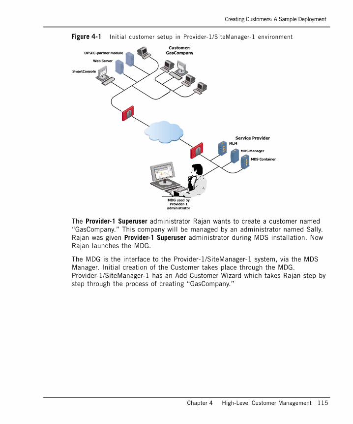
Creating Customers: A Sample Deployment
Chapter 4 High-Level Customer Management 115
Figure 4-1 Initial customer setup in Provider-1/SiteManager-1 environment
The Provider-1 Superuser administrator Rajan wants to create a customer named “GasCompany.” This company will be managed by an administrator named Sally. Rajan was given Provider-1 Superuser administrator during MDS installation. Now Rajan launches the MDG.
The MDG is the interface to the Provider-1/SiteManager-1 system, via the MDS Manager. Initial creation of the Customer takes place through the MDG. Provider-1/SiteManager-1 has an Add Customer Wizard which takes Rajan step by step through the process of creating “GasCompany.”

Creating Customers: A Sample Deployment
116
Figure 4-2 MDG before Customers are added
Rajan inputs details about GasCompany: name, location, contact details. Carmen Sanchez is the Customer’s IT manager on-site who is responsible for GasCompany’s network in Texas, so Rajan inputs Carmen’s contact details. Sally, the administrator who works just down the hall from Rajan, will want to have them handy. Rajan, as a Provider-1 Superuser, is automatically an administrator for GasCompany. He now adds Sally as an administrator. Now Rajan must choose which type of authorizations to give to Sally.
What Type of Administrator?What sort of administrator should Sally be? Sally is going to be handling many different aspects of customer management within the Provider-1/SiteManager-1 environment, but she does not need to create new Customers or be a Superuser. On the other hand, she needs to be able to start and stop the CMA for maintenance or updates. So Rajan assigns her Customer Manager permissions. Rajan also assigns Read/Write permissions for GasCompany to Sally.

Creating Customers: A Sample Deployment
Chapter 4 High-Level Customer Management 117
What Type of Authentication?Rajan must choose an authentication scheme for Sally: either provide a username and password (less secure) or use a certificate (recommended). Rajan chooses authentication via certificate, and generates a certificate for Sally. When Sally logs into the system, she will use this certificate to be authenticated and establish trusted communication. Otherwise...the Provider-1/SiteManager-1 system will not let her in.
Assigning a ComputerUsing the comprehensive Add Customer Wizard, Rajan assigns permission to Sally to use her computer to launch SmartConsole applications and the MDG, in order to manage GasCompany’s network. Rajan does not want every computer to be able to launch applications for this customer: it would be a security breach.Figure 4-3 Sally is now a Customer Manager

Creating Customers: A Sample Deployment
118
Assigning a CMARajan names the first CMA GasCompany_CMA. The CMA is a virtual SmartCenter server. Rajan chooses an MDS Manager/Container in the service provider site to “house” the CMA. Even if there were many other customers, GasCompany does not have a very complex environment, so Rajan is not worried about putting the Customer on any MDS in the system. Of course, if the system was full of Customers with major accounts and thousands of supported gateways, Rajan would think twice about which MDS to use!
To provide it with a virtual IP, which is mapped to the MDS interface, Rajan has already entered a range of virtual IP addresses for the MDS interface in the MDS configuration window. The Provider-1/SiteManager-1 system automatically maps this range to the MDS interface. Now, using the Add Customer Wizard, Rajan creates the CMA and uses the Get Automatic IP Address option. The Provider-1/SiteManager-1 system assigns the first available virtual IP address to GasCompany_CMA.
The CMA license is already on-hand: Rajan ordered it in advance. Using the Add Customer Wizard, Rajan imports licensing data and creates the CMA.
GasCompany wants fail-over security, so Rajan uses the Add Customer Wizard to create a mirror (secondary) CMA named GasCompany_CMA_HA on a different MDS Container. (The mirror CMA must be created on an MDS other than the one hosting the primary CMA).
The CMAs are now up and running; they have been “started” by the system.

Creating Customers: A Sample Deployment
Chapter 4 High-Level Customer Management 119
Figure 4-4 A ‘started’ CMA can begin managing GasCompany’s network
Rajan has completed the basic steps involved in introducing a customer into the Provider-1/SiteManager-1 setup.
Having created a customer’s CMA, it is time to establish a connection between the Active CMA and the VPN-1 Pro gateways it will manage.
There are two processes involved. Sally, the Customer Manager will launch SmartDashboard from the CMA and create a gateway object with the IP address of the gateway. Additionally, the gateway managing the Provider-1/SiteManager-1 management network must allow communication between the CMA and the customer’s gateways. This is described further in Chapter 6, “Working in the Customer’s Network”.
Then Rajan, the Provider-1 Superuser, creates appropriate security rules for the Provider-1/SiteManager-1 management network gateway to allow communication between the CMA and the customer’s gateways. This is described briefly in Chapter 3, “Provisioning the Provider-1 Environment”.

Creating Customers: A Sample Deployment
120
Connecting to a Customer NetworkThe Customer network is defined not at the Provider-1/SiteManager-1 setup level but rather at the customer level, through SmartDashboard. Now Sally is ready to take over. GasCompany’s actual network components are defined in SmartDashboard, which is launched from the CMA. Sally configures the customer/branch’s network by creating objects for the gateways, routers, hosts, users, user groups, servers, and other network components, using SmartDashboard. These activities, which relate exclusively to a specific customer’s network, are addressed in Chapter 6, “Working in the Customer’s Network”, and in further detail in the SmartCenter Guide.
Communication must also be permitted between the Provider-1/SiteManager-1 network and the customer’s gateways. Rajan inserts appropriate rules permitting the CMAs to communicate from the Provider-1/SiteManager-1 network with the customer’s VPN-1 Pro gateways.
Once Sally defines gateways and links them to the GasCompany_CMAs, these gateways are displayed in the MDG. However, information about different individual customer networks is isolated securely and privately from other customer networks. The customer network’s details are stored in CMA databases which are isolated from each other. Only a CMA’s secondary (High Availability) CMA will share access to the CMA’s customer network information.
Creating more CustomersAs more customers/branches are added in the Provider-1/SiteManager-1 setup, the same procedure is followed. A new customer/branch is defined, assigned an administrator and a GUI Client, and a CMA is created for the customer/branch. Rajan assigns two more new Customers to Sally, then another one to Monisha. The Provider-1/SiteManager-1 network is now connected to four customer sites. And it’s just the beginning.

Creating Customers: A Sample Deployment
Chapter 4 High-Level Customer Management 121
Figure 4-5 Creating more customers/branches
Creating more MDSsAt some point the service provider’s MDS Container will be handling a heavy load, with many CMAs supporting a large number of VPN-1 Pro gateways, network objects, and users. It will be a good idea to start creating any new customers on a different MDS Container, perhaps adding a Container to handle the load. Once the new Container is setup, the process for creating new customers is the same. A new customer/branch is defined, assigned an administrator and a GUI Client, and a CMA is created for the customer/branch.

Inputting Licenses using the MDG
122
Figure 4-6 MDG with many Customers
Inputting Licenses using the MDG
In General View - MDS Contents ModeWhen requesting a CMA license from the Check Point licensing center, you provide the IP address of the virtual network interface on the MDS on which the CMA will reside. You receive a file that includes the license string. The file contains details such as the computer IP, the expiration date of the license; the SKU/Features and a Signature Key. SKU/Features is a string composed of groups of characters, listing the features included in the license. The Signature Key is the license key string, for example: PnrCFr35F-xVO7N9nz3-ebTqwgCtA-BQU69trY.
In SmartUpdate ViewThe MDG includes a SmartUpdate view, which can be used to update licenses for CMA’s and customer network objects, and handle remote software installations and licensing of Check Point and third-party (OPSEC) products. Through the SmartUpdate view it is possible to examine, upgrade and manage licenses for all CMAs.

Inputting Licenses using the MDG
Chapter 4 High-Level Customer Management 123
Figure 4-7 SmartUpdate View — Packages Tab
SmartUpdate uses five keys used to uniquely identify each product package: Vendor, Product (Name), Major Version, Minor Version and OS. This information is accessible through the SmartUpdate View by using the Package Repository view.
SmartUpdate functionality is supported by CPRID, the Check Point Remote Installation Daemon that is the SmartUpdate communications backbone. The CPRID client resides on the MDS and communicates with a CPRID server that resides on the Module. CPRID is part of the SVN Foundation. For more information about SmartUpdate architecture and how it functions in general, see the SmartCenter guide. Note that the SmartUpdate View offers functionality tailored to the Provider-1/SiteManager-1 environment.
Table 4-1 describes the three license types used.

Inputting Licenses using the MDG
124
Table 4-1 License Types
License Meaning
Attached Central License
Check Point NGX R61 uses a Central license. The customer VPN-1 Pro gateway’s license is tied to the IP address of the CMA instead of the IP address of the customer’s module. The benefits are:• Only one IP address is needed for all licenses.• A license can be taken from one module and given to another.The license remains valid when changing the IP address of the module, so there is no need to create and install a new license.When a Central license is attached, it means that it has been both added to the License Repository and installed on a Check Point Node.
Unattached Central License
If a Central license has been added to the License Repository, but is not installed on any Check Point Node, it is available for attachment to any computer belonging to the Customer who owns the license.
Attached Local License
A local license is associated with the IP address of a specific module in a customer’s internal network, and can only be used for the module or SmartCenter server with that IP address. The SmartCenter Server itself requires a Local license. When an NGX R61 Local license is added to the License Repository, it is automatically attached to the remote Check Point Node and cannot be detached from it.
Trial Period License
Check Point products have a 15 day trial period license, during which the software is fully functional and all features are available without a full (or an evaluation) license.

Setup Considerations
Chapter 4 High-Level Customer Management 125
Setup Considerations
IP Allocation for CMAsEach CMA must have a routable IP address. Every time a CMA is started, a Virtual network interface for CMA's virtual IP is created. By default, the virtual network interface will be created on the MDS primary network interface.
During MDS configuration, you may specify a range of virtual addresses for a Container interface. Then, as you create each CMA, the Provider-1/SiteManager-1 system can automatically fetch the next available virtual IP and assign it to the CMA. Alternatively, rather than fetch from a range, you can designate a particular virtual IP to a CMA. Keep the CMAs IPs in mind for routing purposes, as you will need to ensure that your route tables allow communication between CMAs and their customer gateways.
You do not need to create any of the actual virtual IP interfaces on the server. If you would like to host the CMA’s IP address on a different network interface, you can do so by stopping the CMA, removing its virtual IP address definition and modifying the CMA file vip_index.conf.
Assigning GroupsIn some cases, the same operation (such as assigning an administrator or policy) must be performed to many customers with similar security policy needs. By default, each time you select customers to apply an operation, you must go through the entire customers list and check them one by one.
To avoid this time-consuming process and facilitate customer selection, it is recommended that you use customer selection groups, which easily identify customers that can be handled simultaneously. Provider-1/SiteManager-1 has two types of selection groups: customer groups and administrator groups. As opposed to groups created through SmartDashboard, these selection groups are not network objects. Their sole purpose is to facilitate customer or administrator selection.
For details on configuring groups, see “Configuration” on page 126.

Configuration
126
ConfigurationIn This Section
Configuring a New Customer
In This Section
New Customers are created through the Add Customer Wizard, which takes the administrator through all the steps needed to create a customer, assign an administrator and a GUI Client, and create the CMA.
Configuring a New Customer page 126
Creating Administrator and Customer Groups page 129
Changing Administrators page 129
Modifying a Customer’s Configuration page 131
Changing GUI Clients page 131
Deleting a Customer page 132
Configuring a CMA page 132
Starting or Stopping a CMA page 132
Checking CMA Status page 132
Deleting a CMA page 133
Start the Add Customer Wizard page 127
Name the Customer and Enable QoS page 127
Customer Details page 127
Assign Administrators to the Customer page 127
Assign Computers on which Administrators use the MDG page 128
Create the CMA page 128
Add CMA License Details page 128

Configuring a New Customer
Chapter 4 High-Level Customer Management 127
Start the Add Customer Wizard1. In the MDG Customer Contents Mode (the view to which the MDG first opens).
To create a customer, click the New Customer tool in the toolbar, or from the Manage, choose New Customer..., or right-click the Provider-1/SiteManager-1 root and choose New Customer... from the drop-down menu. The Add Customer Wizard will then guide you through the definition of the new customer and the customer’s CMA(s). You can create a primary and secondary CMA for the customer at the same time.
Name the Customer and Enable QoS2. Give the Customer a name and enable QoS if desired.
Customer Details3. Assign Customer Properties, for example, a contact person, contact e-email, and
contact phone-number.
You can add or delete these information fields via the Manage > Provider-1/SiteManager-1 Properties, in the Customer Fields tab.
Global Policy4. Configure Global Policy, including Global SmartDefense.
Assign Administrators to the Customer5. The wizard next prompts you to select administrators. To assign an
administrator to a customer, select the administrator from the Not Assigned column and click Add. You can create administrator groups to facilitate administrator assignment. All members of the group you choose are automatically selected, allowing you to Add or Remove them as a group. To create a new administrator, click New Admin.... Then define the new administrator as follows:
1. If you have a Provider-1/SiteManager-1 Superuser permission, you can choose the Administrator’s Provider-1/SiteManager-1 Permission as well.
2. In the Authentication tab, select the administrator’s authentication scheme: password (less secure) or certificate (recommended). If you choose authentication via certificate, in the Certificates tab, create a certificate. It is generated into a file and should be given to the administrator.

Configuring a New Customer
128
3. Define permissions: Read/Write or a Read Only permission to the customer’s network objects and policies. These permissions should also be specified when configuring the customer’s modules. An Edit Administrator Permissions window, corresponding to the cpconfig tab, can be displayed through the Administrators window in two ways: automatically, when you click Add to assign an Administrator to a customer, or manually, by selecting an Administrator from the Assigned list and clicking Permissions...
Assign Computers on which Administrators use the MDG6. Specify the GUI Client (computer) from which administrators are authorized to
use the MDG and/or SmartConsole application.
Create the CMA 7. Decide to create one or two Customer Management Add-ons (CMAs). You can
create two CMAs if you want to enable High Availability. The mirror (secondary) CMA must be created on a different MDS Container from the one housing the primary CMA, so you must have at least two Containers in the system to created CMA High Availability. If you create two CMAs, steps 7 to 9 apply for each CMA.
8. Define the CMA. Select the Container MDS on which this CMA will be maintained. You can provide a virtual IP address for the CMA, or the Provider-1/SiteManager-1 system can also produce a virtual IP from a range that you specify per MDS. You can fetch an IP address (for the MDS) by using the Get Automatic IP Address button. If you have already set up a host table specifying a name and virtual IP for the CMA, you can Resolve by Name, fetching the IP address matching the name of the CMA.
Add CMA License Details9. Next, fill in the license information. When you request a license from the Check
Point licensing center, you receive a file that includes the license string. You can import the file with the license by clicking the Fetch from file... button.
Or, you can click Add to access the Add License window. Then, you can quickly and easily enter the license string data from the email into the Add License window, as follows:
1. In the file, highlight the entire license string (that starts with cplic putlic... and ends with the last SKU/Feature) to the clipboard. Choose Copy from the Edit menu of the your email application.

Creating Administrator and Customer Groups
Chapter 4 High-Level Customer Management 129
2. In the Add License window, click Paste License to paste the license details you have saved on the clipboard into the Add License window. The license details will be inserted into the appropriate fields, described below.
To Validate your license, click Calculate to figure out your Validation Code, and compare with the validation code received from the User Center.
10. For further license management use the following, click Fetch From File to import one or more licenses from a license file. In the Open window, browse to the license file, select it and click Open. The license that belongs to this host is added. The Licenses list displays the details of the CMA’s license entered through the Add License window.
11. To define a mirror CMA, repeat the instructions for adding the first CMA, steps 6 and 7. The mirror (secondary) CMA must be created on a different MDS from the one housing the primary CMA. See Chapter 10, “High Availability”.
12. The new customer appears in the customer tree.
Creating Administrator and Customer Groups
Creating Customer Selection GroupsTo create a customer selection group in any MDG View, select Manage > Selection Groups > Customer Groups... from the menu. Click Add to add a group, then name the group, and select members. To add customers to the selection group, select them in the Not in Group list and click Add. To remove customers click Remove.
Creating Administrator Selection GroupsTo create a customer selection group in any MDG View, select Manage > Selection Groups > Administrator Groups... from the menu. Click Add to add a group, then name the group, and select members. To add administrators to the selection group, select them in the Not in Group list and click Add. To remove administrators click Remove.
Changing AdministratorsTo add/delete/edit a customer’s administrators, change administrator permissions, or edit an administrator's password, you can open the Administrators view and perform these specialized activities relating to administrators.

Changing Administrators
130
Figure 4-8 Administrators View
To make various changes to an administrator, select an administrator and from the right-click drop down menu choose an action.
To create a new administrator, select New Administrator.... from the Manage or right-click the Provider-1/SiteManager-1 root and select Add Administrator. Step through the procedures, which are the same as in the Add Customer Wizard. See “Assign Administrators to the Customer” on page 127.

Modifying a Customer’s Configuration
Chapter 4 High-Level Customer Management 131
Modifying a Customer’s ConfigurationTo modify a customer, select the customer and then choose Configure... from the Manage, or click the configure tool, or double-click the customer. The Customer Configuration window allow you to change all the basic customer settings.
Changing GUI ClientsTo add/edit/switch/delete the GUI Client that a Customer is managed from, you can open the GUI Client view and reassign the Customer to a different GUI Client:Figure 4-9 GUI Clients window (showing Customers per GUI Client)
Select a GUI Client, and from the right click menu, choose an action.
To create a new GUI Client, select New GUI Client.... from the Manage or right-click the Provider-1/SiteManager-1 root and select New GUI Client. Step through the procedures, which are the same as in the Add Customer Wizard. See “Assign Computers on which Administrators use the MDG” on page 128.
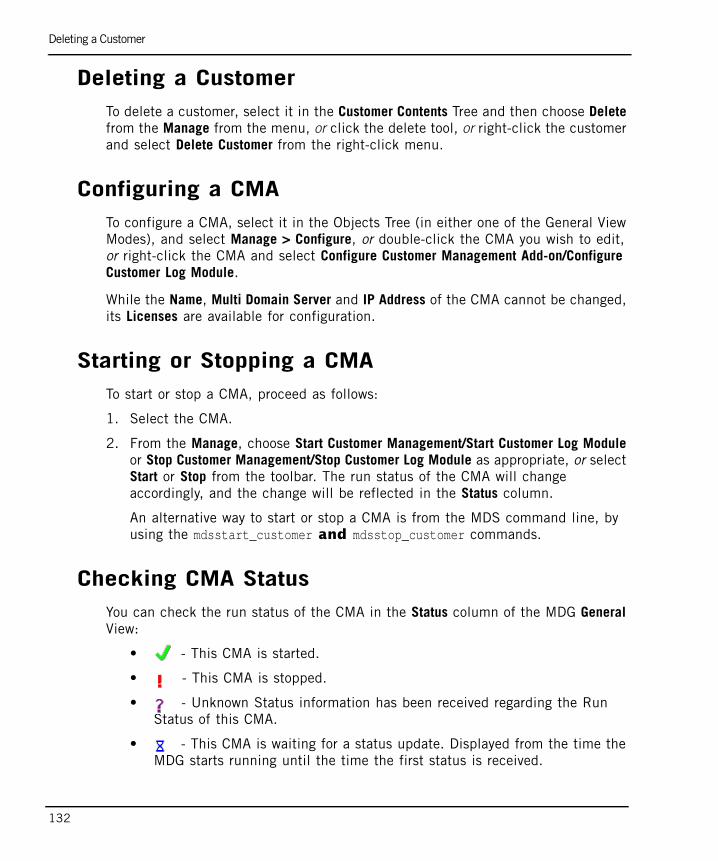
Deleting a Customer
132
Deleting a CustomerTo delete a customer, select it in the Customer Contents Tree and then choose Delete from the Manage from the menu, or click the delete tool, or right-click the customer and select Delete Customer from the right-click menu.
Configuring a CMATo configure a CMA, select it in the Objects Tree (in either one of the General View Modes), and select Manage > Configure, or double-click the CMA you wish to edit, or right-click the CMA and select Configure Customer Management Add-on/Configure Customer Log Module.
While the Name, Multi Domain Server and IP Address of the CMA cannot be changed, its Licenses are available for configuration.
Starting or Stopping a CMATo start or stop a CMA, proceed as follows:
1. Select the CMA.
2. From the Manage, choose Start Customer Management/Start Customer Log Module or Stop Customer Management/Stop Customer Log Module as appropriate, or select Start or Stop from the toolbar. The run status of the CMA will change accordingly, and the change will be reflected in the Status column.
An alternative way to start or stop a CMA is from the MDS command line, by using the mdsstart_customer and mdsstop_customer commands.
Checking CMA StatusYou can check the run status of the CMA in the Status column of the MDG General View:
• - This CMA is started.
• - This CMA is stopped.
• - Unknown Status information has been received regarding the Run Status of this CMA.
• - This CMA is waiting for a status update. Displayed from the time the MDG starts running until the time the first status is received.

Deleting a CMA
Chapter 4 High-Level Customer Management 133
Deleting a CMABefore deleting a CMA, make sure to stop it. Select it in the MDG Customer Contents view and then choose the delete tool in the menu bar, or Manage > Delete, or right-click the CMA and select Delete Customer Management Add-on/Delete Customer Log Module (respectively) from the right-click menu.

Deleting a CMA
134

135
Chapter 5Global Policy Management
In This Chapter
Security Policies in Provider-1 page 136
Global SmartDashboard page 142
Creating a Global Policy through Global SmartDashboard page 145
Global SmartDefense page 147
Assigning Global Policy page 152
Configuration page 158

Security Policies in Provider-1
136
Security Policies in Provider-1In This Section
Introduction to Security Policies in Provider-1A VPN-1 Pro gateway (a “firewall”) at a network boundary acts as an enforcement point that inspects and provides access control for all traffic passing through the gateway. Traffic that does not pass through the enforcement point is not controlled. Figure 5-1 A VPN-1 Pro enforcement point inspects all traffic that crosses it
The VPN-1 Pro administrator is responsible for implementing the company Security Policy. VPN-1 Pro allows the company Security Policy to be consistently enforced across multiple firewalls. To achieve this, an enterprise-wide Security Policy Rule Base is defined for a Customer through the CMA. SmartDashboard is used to install the policy, and distribute it to the Customer’s gateways. Granular control of the policy is possible by having specific rules apply only on specific enforcement points.
Introduction to Security Policies in Provider-1 page 136
The Need for Global Policies page 138
The Global Policy as a Template page 139
Global Policies and the Global Rule Base page 140

Introduction to Security Policies in Provider-1
Chapter 5 Global Policy Management 137
Security policies are created to enforce security rules. Provider-1/SiteManager-1 administrators can create security policies and rules tailored to a specific Customer, or for many Customers of a certain type. In the Provider-1/SiteManager-1 environment, administrators create a Customer’s security policies for a specific set of gateways, using the CMA.
The CMA, which is the equivalent of the SmartCenter server in the VPN-1 Pro model, allows administrators to create rules which apply to specific Customer networks and their firewalls. For information about using SmartDashboard to construct security policies, see the SmartCenter User Guide.Figure 5-2 How security policies are created
The administrator directly defines a Customer’s network and the security policy and QoS policy via the CMA, using SmartDashboard. SmartDashboard is launched for a particular CMA, and the administrator defines all the network objects, gateways, hosts and nodes in the Customer’s network. The administrator also uses SmartDashboard to create a set of rules (a rule base) which compose a security policy. The CMA then downloads (or installs) the Security Policy to the Customer’s VPN-1 Pro gateways.
The fundamental concept of the security policies’ rule base is “That which is not explicitly permitted is prohibited.” The rule base specifies what communication will be allowed to pass and what will be blocked, and specifies the source and destination of the communication, what services can be used, at what times, and whether to log the connection.
When creating rules for the system, an administrator must consider the needs of the organization:

The Need for Global Policies
138
• What are the physical and logical components that make up the organization? Each component of the organization needs to be accounted for. Every server, every printer, every resource, etc.
• Who are the users and administrators and how should they be divided into different groups?
• What are the access needs of these users?
• Are there public access needs?
• What types of access must be prevented?
A substantial amount of planning should go into deciding how to define the Customer network (by creating representative objects), and how they should be implemented.
The Need for Global PoliciesBesides security policies for a specific set of gateways, administrators need to create policies which apply to the entire Provider-1/SiteManager-1 environment or to a group of Customers. The separation between different levels of policies, and different types of policies, means that Customer-level security rules do not need to be reproduced throughout the entire Provider-1/SiteManager-1 environment.
Security policies can be created and privately maintained for each Customer, ensuring a Customer’s security integrity. Global policies enforce security for the entire Provider-1/SiteManager-1 system or for a group of Customers.

The Global Policy as a Template
Chapter 5 Global Policy Management 139
Figure 5-3 Policy creation workflow
The Global Policy as a TemplateSecurity policies can be created and privately maintained per Customer, ensuring a Customer’s security integrity, but some security rules are enforced by all Customers. Global policies can serve as security templates with rules that are applied to many Customers, and their individualized security policies.
Types of Global Policies can be designed for groups of Customers with similar security needs. This eliminates the need to recreate identical policies for each Customer. This feature greatly improves management efficiency. A service provider may use Global Policy rules to provide Customers with access to common MSP services but does not allow Customers to access private information about each other.
An MSP may provide several basic types of security policies. Rather than recreate the rule base for each new Customer, they can create a Global Policy for banks, a different Global Policy for independent dentists and therapists, and a Global Policy for small businesses, such as grocery stores, florists, gas stations or tax accountants.

Global Policies and the Global Rule Base
140
An enterprise may use a Global Policy to set corporate wide policies. For example, an airline company with many branches and sales-offices, sales points and Customer check-in facilities may want to set rules for many different types of standard access needs. Rather than painstakingly recreating the same rule or set of rules for each branch, a global security policy can secure access across the board.
Global Policies and the Global Rule BaseGlobal policies are created using the global rule base, which contains a hierarchy of rules. In a Global Policy, you define common (global) rules, which are given priority in the rule base. These rules can be distributed (or assigned) to whichever Customers you choose. The Global Policy rule base is similar to the management rule base, except that it includes a demarcation or a “place holder” for Customer-specific rules.
The placeholder signifies that all the rules before and after it are global rules. The rule base layout is hierarchical: the most important global rules are highest up in the rule base. They take precedence over the Customer rules. Global rules that are designated as being of lower priority than Customer rules appear below the place holder.
The rules of the Global Policy are not specific to a single policy of single Customer, but apply to all Customers assigned the Global Policy. Figure 5-4 Sample Global Policy
Global rules can serve many uses. They can be used to rapidly implement defense against new cyber attacks or viruses. They can be used to prevent logging for specific types of traffic in order to reduce the amount of information in log files. They can be used to set up rules for CMA communication management, such as allowing additional GUI Clients to be implemented at Customer sites.
Only one set of objects is used for all the Global Policies. The Global Policies database contains this set of objects, which can be used in any global rule in any Global Policy. The administrator creates these objects using Global SmartDashboard. Global Object icons are displayed with a purple G. For example, a Global Check Point Node has the icon.
Global Policies and the Global Rule Base
Chapter 5 Global Policy Management 141
Global policies can be assigned to one or more Customers. Once Global Policies are assigned to a Customer’s CMA, they become part of the CMA’s rule base. The entire CMA’s rule base, including assigned global rules, can then be installed onto selected VPN-1 Pro gateways.

Global SmartDashboard
142
Global SmartDashboardIn This Section
Introduction to Global SmartDashboardIn order to create Global Policies, the Global SmartDashboard is used to create the Global Policy Rule Base. The Global SmartDashboard, launched off the MDS Manager, represents the network and is used to create rules and network objects at the Provider-1/SiteManager-1 system level.
SmartDashboard differs from Global SmartDashboard in that it applies only to the Customer level and below. After a Global Policy is assigned to a Customer, SmartDashboard for the Customer’s CMA will show global rules automatically inserted either above or below editable Customer rules. The Customer administrator can create or edit Customer rules using SmartDashboard, and then install the policy onto the Customer’s VPN-1 Pro gateway.
Once a Global Policy is assigned to a Customer, the global rules are displayed as read-only in the Customer’s SmartDashboard. A Customer administrator cannot edit global rules or Global Objects from SmartDashboard. Figure 5-5 How global rules appear in the Customer’s SmartDashboard
Introduction to Global SmartDashboard page 142
Global Services page 143
Dynamic Objects and Dynamic Global Objects page 143
Synchronizing the Global Policy Database page 144

Global Services
Chapter 5 Global Policy Management 143
Global Services Default services defined by VPN-1 Pro are available for global use. Other services need to be defined. To avoid collision, ensure that you name services with unique names, that should not be the same as in the CMAs’ databases.
Dynamic Objects and Dynamic Global ObjectsDynamic objects are generic network items such as a host or server object that has no IP specified. The administrator creates them in SmartDashboard, and uses them to create generic rules for Customer’s gateways. At each gateway, the dynamic object can be translated into a specific local computer, host or other network object, with an IP address.
Global rules may similarly use dynamic Global Objects, that are generic items (such as a web server) that can be applied to any network. Global objects are defined through the Global SmartDashboard and are downloaded to the CMAs.
At the global level, an administrator defines dynamic Global Objects in addition to standard Global Objects which are available in the Global SmartDashboard. Once a Global Policy is assigned to a Customer, the dynamic global object is replaced by a corresponding Customer object. This makes it possible to create global rules without requiring that the rule use specific network objects. This allows the administrator to create rules that are “templates.”
A dynamic global object serves as virtual place holder for a network element. The network element type can be anything that the administrator designates, including gateways, hosts, or services, or even groups. A dynamic global object is created in the Global SmartDashboard with the suffix _global (for example, FTPserver_global). This object is applied to a global rule. Figure 5-6 Using a Dynamic Global Object in a global rule
To “translate” the dynamic global object, the administrator creates an object in SmartDashboard with the same name, but with an IP address and other details. The Customer’s database substitutes the dynamic global object in the global rule with the local object from the CMA database. Alternatively, the dynamic global object is replaced with a CMA dynamic object, and the object is assigned an IP at the gateway level.

Synchronizing the Global Policy Database
144
To understand how the dynamic global object is used, let us consider an example. An administrator creates a global rule applying to a dynamic global object representing a generic ftp server. But instead of specifying exactly which ftp servers and their IP addresses will be affected by the rule, the servers are represented by a dynamic global object (FTPserver_global).
In each CMA, the Customer administrator will define a host object with the same name. During the assignment of the Global Policy, the references to the global dynamic object in different rules will be replaced by the reference to the local host object with the same name. The _global syntax triggers the reference replacement mechanism.Figure 5-7 Dynamic Global Object used to represent a host
Synchronizing the Global Policy DatabaseThe Global Policy database is synchronized on all MDS Managers automatically, or manually, depending on the settings. Global policies must be synchronized for the entire system, since they are system-wide security templates, and the entire system uses the same Global Objects. Synchronization is performed when the Global Policy is saved, or at a configurable interval. For more information about synchronization, see Chapter 10, “High Availability”.

Creating a Global Policy through Global SmartDashboard
Chapter 5 Global Policy Management 145
Creating a Global Policy through Global SmartDashboard
Global policies are created using the Global SmartDashboard. Customer policies are made using SmartDashboard launched via the CMA. Let us consider an MSP that wants to implement a rule which blocks unwanted services at Customer sites. The Provider-1 Superuser, Carol, wants to set up a rule which will allows Customer administrators discretion to decide which computers are allowed to access the Internet. Figure 5-8 Carol creates a rule for the web server
Carol launches Global SmartDashboard. She creates a global dynamic object to represent a group of computers that are allowed to access the Internet, and names it gInternetAccessAllowed_Global. She creates a rule using the global dynamic object. Figure 5-9 Rule containing Dynamic Global Object
Once she has created a Global Policy including this rule, she assigns/installs it for specific Customers and their network gateways. Each Customer administrator must create a group object with the same name as in the CMA database. This is done through SmartDashboard. In this way, local administrators translate the dynamic global object into sets of network object from the local database.

Creating a Global Policy through Global SmartDashboard
146
For details about using SmartDashboard, consult the SmartCenter Guide. The differences between the Customer’s SmartDashboard and the Global SmartDashboard are as follows:
Table 5-1 Customer vs. Global SmartDashboard
Feature Customer SmartDashboard Global SmartDashboard
Rule Base Local, applying to the Customer network only.
Global, applying to multiple networks of all Customers assigned this Global Policy.
Consists of Customer Security Rules and Global Rules (in Read Only mode) if the Global Policy is assigned to the Customer.
Consists of both Global Rules and a place holder for Customer rules.
Is not associated with the Customer's other security policies.
Automatically added to all of the assigned Customers’ security policies.
Each Customer policy is independent, with its own rules
All the assigned Customers’ policies share the global rules
Network Objects Local, applying to this network only.
Global, applying to multiple networks of all Customers assigned this Global Policy.
Global Properties Enabled. Disabled (manipulations is through the Customer SmartDashboard).
Saving a Security Policy
Adds the security policy to the list of Customer security policies
Adds the Global Policy to the Global Policies database (and displays it in the Global Policies Tree of the MDG).

Global SmartDefense
Chapter 5 Global Policy Management 147
Global SmartDefenseIn This Section
Introduction to Global SmartDefenseCheck Point's SmartDefense and Web Intelligence protections can now be centrally managed with Provider-1/SiteManager-1. These protections, collectively referred to as SmartDefense, can be commonly configured in the Global SmartDashboard, and then distributed to selected Customers via the Assign Global Policy operation. Each Customer can further customize the settings via the SmartDashboard of their CMA. Managing which Customers receive the common SmartDefense settings is performed through the MDG.
It is important to note that the global nature of Global SmartDefense refers to the ability to set one policy for all subscribed Customers from the MDG. However, the CMA administrator for each Customer can modify the SmartDefense and Web Intelligence protections once they have been installed. So in this case the term global does not confer a meaning of read only, as it does in the case of the Global Security Policy.
Configuring SmartDefense in Global SmartDashboard
The Global SmartDefense Policy is configured on the SmartDefense and Web Intelligence tabs of Global SmartDashboard, as shown in Figure 5-10.
Introduction to Global SmartDefense page 147
Configuring SmartDefense in Global SmartDashboard page 147
Subscribing a Customer to the Global SmartDefense Service page 148
Modifying SmartDefense from the SmartDashboard of a CMA page 150

Subscribing a Customer to the Global SmartDefense Service
148
Figure 5-10 SmartDefense and Web Intelligence in Global SmartDashboard
The SmartDefense and Web Intelligence settings and protections that first appear in Global SmartDashboard are identical to the default settings and protections of SmartDefense for VPN-1 Pro. However, the changes that you save here will be applied to any Provider-1 Customer subscribed to the Global SmartDefense service.
Just as on the regular SmartDashboard, the latest SmartDefense and Web Intelligence protections for Global SmartDashboard can be updated via the Online Update operation, located on both tabs and on the SmartDefense Services tab.
Subscribing a Customer to the Global SmartDefense Service
Any Customer that you want to include in the Global SmartDefense policy needs to be subscribed to the SmartDefense service. This is done on the Assign Global Policy tab that is found in both the Add Customer wizard and when editing the properties of an existing Customer. Figure 5-11 shows the Assign Global Policy tab.
Note - You must have an Enterprise Software Subscription to update SmartDefense and Web Intelligence protections. Enterprise Software Subscriptions are available for purchase at the User Center at https://usercenter.checkpoint.com.

Subscribing a Customer to the Global SmartDefense Service
Chapter 5 Global Policy Management 149
Figure 5-11 Assigning Global Policy to a Customer
Once a Customer is subscribed to the Global SmartDefense service, any changes to the Global configuration of SmartDefense are forwarded to the Customer whenever Global Policy is assigned. See “Assigning Global Policy” on page 152 for details.
The Assign Mode controls how the Global SmartDefense protections and settings assigned to the Customer affect any modifications the Customer administrator has made to SmartDefense on the CMA.
• Override simply erases any changes the Customer administrator has made, replacing them with the latest Global SmartDefense policy.
• Merge preserves the Customer administrator’s changes, but updates all other fields with the latest Global settings.
The ramifications of customizing SmartDefense settings when a Customer is set to Merge mode are detailed in the next section, “Modifying SmartDefense from the SmartDashboard of a CMA”.
Modifying SmartDefense from the SmartDashboard of a CMA
150
Modifying SmartDefense from the SmartDashboard of a CMA
A Customer administrator can always modify the SmartDefense and Web Intelligence settings on the CMA, regardless of whether the Customer is subscribed to the Global SmartDefense service, or of what Assign Mode is set for the subscribed Customer.
SmartDefense can be modified on the CMA in a number of ways:
• Directly changing a setting on the SmartDefense or Web Intelligence tabs
• Performing an Online Update
• Activating one of the settings in Central Configuration
For Customers subscribed to the Global SmartDefense service, the Assign Mode selected controls whether the Customer administrator’s modifications are preserved.
Modifications to SmartDefense on the CMA of a Customer set to Override are erased and replaced by the Global SmartDefense Policy whenever Global Policy is assigned.
Modifications to SmartDefense on the CMA of a Customer set to Merge are preserved whenever Global Policy is assigned.
Ramifications of Modifying SmartDefense on the CMAIt should be understood that for Customers configured for Global SmartDefense Merge mode, once a particular setting is changed and saved by the Customer administrator, subsequent Global SmartDefense assignments will not affect it. A particular setting means the exact property changed, not the whole protection.
An Example
Take for example the IP Fragments protection, located at SmartDefense tab > Network Security > IP and ICMP. If the Customer administrator were to change the property Discard incomplete packets after xx seconds from the default value of 1 to 2 and click Save, that specific property will no longer be affected when Global Policy is assigned. However, changes made in Global SmartDefense to other properties within the IP Fragments protection will appear in SmartDefense for this Customer.

Modifying SmartDefense from the SmartDashboard of a CMA
Chapter 5 Global Policy Management 151
Recommendation
When setting a Customer’s Assign Mode, consider to what extent you want to centrally manage the SmartDefense protections for all your Customers. Check Point recommends setting the Assign Mode to Override for most deployments.

Assigning Global Policy
152
Assigning Global PolicyIn This Section
Introduction to Assigning Global PolicyGlobal Policy, which includes the Global Security Policy and Global SmartDefense, should be assigned to Customers when it is first configured, and whenever you want to implement a change. All Global Policy assign operations are performed from the Global Policies - Security Policies and SmartDefense view.
Assigning Global Policy for the First TimeTo assign Global Policy for the first time, select the target Customer, and from the the Manage menu, select Assign/Install Global Policy. Figure 5-12 illustrates the resulting window.Figure 5-12 Assigning Global Policy to a Customer
Introduction to Assigning Global Policy page 152
Assigning Global Policy for the First Time page 152
Reassigning Global Policy page 153
Reassigning Global Policy to Multiple Customers Simultaneously page 153
Reviewing the Status of Global Policy Assignments page 154
Considerations For Global Policy Assignment page 155
Global Policy History File page 157

Reassigning Global Policy
Chapter 5 Global Policy Management 153
From here you can select from the drop-down window the Global Policy to assign to the selected Customer.
Note that if the Customer is subscribed to the SmartDefense service, the window displays the Customer’s SmartDefense Assign Mode.
Reassigning Global PolicyAfter assigning Global Policy to a Customer, you will need to reassign it each time you want to implement a global change, either to the Security Policy or SmartDefense. To reassign Global Policy, select the target Customer, and from the the Manage menu, select Reassign/Install Global Policy. Figure 5-13 illustrates the resulting window.Figure 5-13 Reassigning Global Policy to a Customer
Reassigning Global Policy to Multiple Customers Simultaneously
Global Policy can be reassigned to multiple Customers at the same time. From the Manage menu, select Reassign Global Policy and SmartDefense to Customers (there is also a toolbar button that performs this function). Figure 5-13 illustrates the resulting window.
Note - To configure a Customer for SmartDefense or to change its Assign Mode, see “Subscribing a Customer to the Global SmartDefense Service” on page 148.

Reviewing the Status of Global Policy Assignments
154
Figure 5-14 Reassigning Global Policy to multiple Customers
Reviewing the Status of Global Policy AssignmentsThe status of the Global Security Policy and Global SmartDefense is reported per Customer in the Security Policies and SmartDefense mode of the Global Policies view, illustrated in Figure 5-13).Figure 5-15 Global Policy statuses

Considerations For Global Policy Assignment
Chapter 5 Global Policy Management 155
In this window, each Customer is displayed under the Global Security Policy to which it is assigned, or under the category No Global Policy. The time and date at which the Global Policy was assigned to each Customer is reported, and a status indicator shows whether that assignment is the most up-to-date version of the Global Policy.
When a change is made in Global SmartDashboard, either to a Global Security Policy or to the Global SmartDefense, the change will be reflected in the Global Policy state of each Customer assigned the relevant Policy. (A green check mark indicates that the Policy is up-to-date, while a red exclamation mark indicates that since the Policy was assigned, it has changed, and should be reassigned.)
Considerations For Global Policy Assignment
In This Section
Introduction to Considerations for Global Policy AssignmentWhen assigning a Global Policy to one or more Customers, Global Objects are copied to the database of the Customer’s CMA. Whether all the Global Objects in the database are copied, or only those related to the Global Policy, can be configured per Provider-1/SiteManager-1 Customer in the Customer Configuration window, (which can be accessed by selecting Manage > Configure when selecting a Customer in the General-Customer Contents view).
Rules belonging to the Global Policy package being assigned are added above and below the rules inside ALL local policies defined in that CMA database.
After the Global Policy is assigned, when issuing the “install policy” command for a CMA’s gateways, the gateways will receive the most updated CMA policy containing the latest updates from the Global Policy. Changes may be made to a Global Policy, after which the Global Policy is reassigned to one of more Customers.
Introduction to Considerations for Global Policy Assignment page 155
Assigning Policy for the First Time page 156
When you Change a Global Policy page 156
Assigning a Different Global Policy page 156
Global Object Transfer Method page 157

Considerations For Global Policy Assignment
156
When a Customer’s CMA then installs the updated policy to the Customer gateways, any modifications to global and local objects/ rules are updated on the selected gateways.
The assign and install procedure are two separate processes. The administrator can re-assign a Global Policy without installing a local policy to Customer gateways.
Assigning Policy for the First TimeOnce you create a Customer’s internal network, you will want to create a policy for the Customer. The first step may be creating a Global Policy template for general use by different types of Customer. This allows you a certain amount of flexibility in how you manage security policy assignment.
Global policies are designed in Global SmartDashboard, but the assign/install procedure is handled through the MDG. The MDG provides a Global Policy Mode which give you a few options to handle the procedure of assigning Global Policies. The Global Policy is assigned to the Customer’s CMA.
When you Change a Global PolicyIf you change the Global Policy, you will have to reassign it to all the Customers who have been assigned the policy, and reinstall it onto the Customer’s gateways.
Re-install the Customer’s network policy to a Customer’s gateways when:
• You have made changes to a Global Policy and reassigned it to the CMA, without installing the updated policy to the Customer’s gateways or,
• When you have made changes to the Customer’s network policy.
If you have network load considerations, rather than install the gateways all at once, you may prefer to perform the procedure in stages. You can re-install a current policy to Customers’ gateways (the Install Last Policy command). Or, install on selected gateways by right clicking a Customer and selecting Reassign/Install Global Policy....
Assigning a Different Global PolicyTo assign a different Global Policy to a Customer, use the same procedure as for initially assigning a Global Policy to a Customer. The Global Policy is overwritten when a new one is assigned.

Global Policy History File
Chapter 5 Global Policy Management 157
Global Object Transfer MethodDuring Customer configuration, you define for each Customer how the Global Policy database will transfer objects during global security policy assignment (this is located in the Add Customer Wizard — Assign Global Policy tab). When Global Policies are assigned to CMAs, two methods can be used to transfer all the information to the CMA’s database from the Global Policy database.
It is possible to assign all Global Objects when assigning the Global Policy to a CMA. Or it is possible to assign only objects required by the rule base of the Global Policy assigned to the CMA. This includes objects directly or indirectly referenced by rules, such as network objects contained in groups. Indirectly references objects will also be copied to the CMA’s database, and the administrator will see them in both group and individually.
You can decide to change settings later, but be careful when changing settings. Consider the following scenario: a Customer assigns a Global Policy and transfers all the Global Objects. All objects are copied to the global database. When a Global Policy is re-assigned with just those objects relevant to the Global Policy assigned, extraneous objects not used by the Global Policy will be removed from the Customer’s configuration database. However, if these objects are used by a Customer’s network security rules or objects, the assignment operation will terminate (an error message lists the objects that prevented the operation from proceeding).
Global Policy History FileEach Customer’s log directory includes a history file (named gpolicy.log) which maintains a summary of all actions taken by the Global SmartDashboard that affect the Customer. It records all actions taken, including assigning Global Policies to a CMA and installation on a remote gateway. The file includes time, operations performed, Global Objects added, and problems. To access this file, see “Viewing the Customer’s Global Policy History File” on page 161.

Configuration
158
ConfigurationIn This Section
Assign/Install a Global Policy To assign, reassign, install or remove policies for Customers, you must be a Superuser (either a Customer Superuser or a Provider-1 Superuser. All these actions are performed in the MDG, using the Global Policies view.
You cannot assign a Global Policy to a Customer if a Read/Write SmartDashboard is logged in to the Customer’s CMA. First, close SmartDashboard and then assign the Global Policy. You can, however, assign a Global Policy to a Customer if there is a Read Only SmartDashboard logged in to the CMA. The changes won't be displayed in SmartDashboard until it is disconnected from and then reconnected to the CMA.
Assign to Many Customers: How To Assign/Install from a Global Policy ObjectUse the following method to create a Global Policy, then assign it to several Customers at once. You can also install a policy to all the Customers’ gateways at the same time. If a Customer already has a different Global Policy, it is overwritten.
1. Select the desired Global Policy. Choose Manage > Assign/Install Global Policy..., or right-click the Global Policy and choose Assign/Install Global Policy... from the menu. Select the Global Policy Name of the Global Policy you want to install (for example, Standard_Global_Policy).
2. Check the Customers to which you want to assign this Global Policy in the Unassigned to selected Policy list.
Assign/Install a Global Policy page 158
Reassigning/Installing a Global Policy on Customers page 159
Reinstalling a Customer Policy onto the Customers’ Gateways page 160
Remove a Global Policy from Multiple Customers page 161
Remove a Global Policy from a Single Customer page 161
Viewing the Customer’s Global Policy History File page 161
Global Policies Tab page 161
Global Names Format page 162

Reassigning/Installing a Global Policy on Customers
Chapter 5 Global Policy Management 159
3. To install the policy on all the gateways of the Customers to which the policy is assigned, check Install Policy on assigned Customers. You can choose to install a policy on specific gateways. If you want to choose specific gateways and not install to all the gateways at one time, perform the assign/install via the Customer object.
4. Click OK. A Global Policy Assignment progress window lets your follow each step of the procedure, as the Global Policy is enforced on the selected Customer’s CMAs. You can track installation attempts using the History file.
Assign to One Customer: Assign/Install from a Customer ObjectSelect a Customer that does not have a Global Policy, and assign one of the Global Policies you have created. This method gives you more control over the installation procedure for particular Customer gateways.
For Customers that already have a Global Policy, the option will be to Reassign/Install Global Policy.
1. Select a Customer, then choose Manage > Assign/Install Global Policy..., or right-click the Customer and select Assign/Install Global Policy...
2. The Assign/Install Global Policy window allows you to select the policy to be installed. Select one or more gateways. A policy must already have been installed on the gateways, or the operation will not work. Click OK.
3. The Global Policy is assigned to the Customer’s CMA and the Customer policy is re-installed on the selected gateways.
Reassigning/Installing a Global Policy on Customers
Once a Customer has been assigned a Global Policy, it is possible to update the policy by re-assigning it.
To Reassign/Install a Global Policy for a Specific Customer who already has been Assigned a Global PolicyWhen performing a Reassign/Install the user does not choose the policy. The policy is already selected. You can also re-install the Customer policy to the Customers’ gateways at the same time, but note that this is for all the gateways at once and will only work if there is already a Customer policy resident on the gateway.
Reinstalling a Customer Policy onto the Customers’ Gateways
160
1. Select a Customer, then choose Manage > Reassign/Install Global Policy..., or right-click the Customer and select Reassign/Install Global Policy...
2. The Reassign/Install Global Policy window will display the policy currently installed.
3. Select the specific gateways for which to re-install the policy. Click OK. The Global Policy is assigned to the Customer’s CMA and the resident Customer policy is re-installed on the selected gateways.
To Reassign/Install a Global Policy for Multiple Customers1. Select a Global Policy, then choose Manage > Reassign/Install Global Policy..., or
right-click the Global Policy and select Reassign/Install Global Policy...
2. Select Customers in the Assigned to Selected Policy list.You may choose to Select All, or select (click) Customers in the Assigned to Selected Policy list. To see Customer details, click Properties. To facilitate Customer selection, click Select by Group...
The Customer Selection Groups window is displayed, listing all predefined Customer Selection Groups. All members of the group you choose are automatically selected.
3. If you would also like to install the policy on the Customer’s gateways, check Install last Policy on all gateways of assigned Customers. The Global Policy is assigned in parallel to CMAs of all the Customers.
Reinstalling a Customer Policy onto the Customers’ Gateways
The Install Last Policy window allows you to select a group of Customers and re-install their Customers’ policies onto their gateways. Only use this method if the gateways already have a policy installed. Proceed as follows:
1. Select Manage > Install Last Policy... Select Customers from the Show drop-down list. You may choose All Customers (the default setting), Only Assigned Customers or Only Unassigned Customers.
2. Check the Customers on which you want to install the policy in the Available Customers list. Click OK to apply re-install the policy.
The policy will be installed on all the gateways of the selected Customers.

Remove a Global Policy from Multiple Customers
Chapter 5 Global Policy Management 161
Remove a Global Policy from Multiple Customers1. Select the Global Policy and choose Manage > Remove Global Policy from
Customers..., or right-click the policy and select Remove Global Policy from Customers... from the right-click menu.
2. Check Customers in the Assigned to selected Policy list. To remove the policy from all Customers, click Select All. Customers from which the Global Policy has been removed are automatically assigned to the No Global Policy group.
Remove a Global Policy from a Single CustomerTo remove a Global Policy from only single Customer, proceed as follows:
1. Select the Customer and right-click and choose Manage > Remove Global Policy, or choose Remove Global Policy from the Manage.
2. You are asked whether you are sure you want to remove this Customer from the Global Policy. Click Yes to confirm. The Customer is automatically assigned to No_Global_Policy.
Viewing the Customer’s Global Policy History FileTo view the Customer’s history file, select a Customer, right-click and choose View History File..., or from the Manage, select View History File....
Global Policies TabThe Manage > Provider-1/SiteManager-1 Properties menu > Global Policies tab allows you to specify how Global Policies are to be assigned to Customers and installed on their Modules.
Policy Operation Options• Perform Policy operations on... Customers at a time — each Policy operation is
performed for a group (segment) of Customers at a time. This field allows you to specify the maximum number of Customers per segment. For example, if there are 5 Customers in the system and the segment number is 2, a Global Policy assign operation will be divided as follows:
1. The operation is performed on the CMAs of the first two Customers.
2. The operation is performed on the CMAs of the next two Customers.

Global Names Format
162
3. The operation is performed on the CMA of the fifth Customer.
• Install Security Policy only if it can be installed on all Modules — specify that an installation succeeds only if the Policy is installed on each and every one of a Customer’s Modules. If the installation on any of the Modules fails, then the whole installation fails and the previous Policy remains installed.
• Install Security Policy on cluster, only if it can be installed on all cluster members
— for each Cluster, the installation succeeds only if the Policy is installed on each and every cluster member. If the installation on any of the clusters members fails, then the whole installation for this cluster fails and the previous Policy remains installed. It is recommended that you enable this option.
Global Names FormatThe Manage > Provider-1/SiteManager-1 Properties menu > Global Names Format window allows the user to define a template for Gateway Global Names, that consists of the original name of the Module, the name of the Customer and other details. When enabling the Modules for Global Use, an automatic suggestion for an appropriate name will be offered, based on this template.
The configurable fields are:
• Global Name - A name is automatically suggested. You can use the default name suggested, which is in the format g<GATEWAY>_of_<CUSTOMER> where the name of the Module and the Customer are the variables. For example, a template defined as g<GATEWAY>_of_<CUSTOMER> for gateway MyGateway of Customer MyCustomer, will result in the suggested name gMyGateway_of_MyCustomer.
The global name should be self explanatory and easy to understand and therefore the template must consist of the Customer's name and the Module's original name. The Administrator can later choose to override the template and create a Global Name which can be any unique legitimate string.
• VPN Domains - The additional configurable part of the template is the suffix for the VPN domain object. The template for the domain object contains the Global Name and the suffix. For example, if the defined suffix template is _Domain, the name of the VPN Domain will be gMyGateway_of_MyCustomer_Domain.

163
Chapter 6Working in the Customer’s Network
In This Chapter
Overview page 164
Installing and Configuring for VPN-1 Pro Gateways page 167
Managing Customer Policies page 168
Working with CMAs and CLMs in the MDG page 169

Overview
164
Overview Management within the customer network is much the same for a Provider-1/SiteManager-1 customer as it is in the VPN-1 Pro management model, but with a few key differences. In the VPN-1 Pro management model, policy management is handled through the SmartCenter server. In the Provider-1/SiteManager-1 model, policy management is handled by the Customer Management Add-on (CMA).
Customer Management Add-on (CMA)CMAs are the Provider-1 equivalent of VPN-1 Pro SmartCenter Servers, and support all VPN-1 Pro features. Via the CMA, a customer administrator defines, edits and installs the customer’s security and QoS policies to the customer’s gateways. Each Customer can have either one or two CMAs, where the second CMA is defined for High Availability purposes. In this case, one of the CMAs has to be Active and the other has to be Standby.
In addition, a SmartCenter server can also be added as a backup of the Customer's CMAs. For details, see “CMA Backup using SmartCenter Server” on page 232.
Let’s look at a deployment. The CMA (the SmartCenter equivalent) is located on the MDS within the Provider-1/SiteManager-1 network.Figure 6-1 Customer network and service provider environment

Administrators
Chapter 6 Working in the Customer’s Network 165
Once you have created a customer’s CMA, you can start defining its policies, as described in the SmartCenter Guide. Gateways are “defined” in the Provider-1 environment and managed via the Customer’s CMA. VSX is described in the VSX User Guide.
Remember that routing must be set up to enable communication between Customer’s gateways and the Customer’s CMA(s). Traffic must be allowed between the Provider-1 management network gateway and Customer’s gateways. It should also be enabled for SmartConsole Client applications and CMA connections. Access rules must be set up as appropriate in Customer gateways’ rule bases.
If Logging is set up for the Customer network, or High Availability is enabled, routing must support these functions. See Chapter 7, “Logging in Provider-1”, and Chapter 10, “High Availability”, for further details.
AdministratorsAdministrators are assigned in a way that is slightly different to the way it is done in the VPN-1 Pro management model, as it is centralized through the Provider-1 environment. Two types of administrators are assigned to manage specific Customers’ networks: Customer Managers and None administrators.
For details about the different types of administrators and their levels of system permissions, see Chapter 1, “Introduction”.
SmartConsole Client ApplicationsAdministrators use the following SmartConsole Client applications to design, manage, monitor and log the firewall enforcement policies:
• SmartDashboard is used by the system administrator to define and manage the Security Policy. From this SmartConsole you can create and define networks, gateways, hosts, user groups, services, and policy rules. You can also access many Check Point features and add-ons.
• SmartView Tracker is used for managing and tracking logs throughout the system.
• SmartUpdate is used to manage and maintain a license repository, as well as to facilitate upgrading Check Point software.
• SecureClient Packaging Tool is used to define user profiles for SecuRemote/SecureClient clients.

SmartConsole Client Applications
166
• SmartView Monitor is used to monitor and generate reports on traffic on interfaces, Provider-1/SiteManager-1 and QoS modules, as well as on other Check Point System counters. It is also is used for managing, viewing alerts and testing the status of various Check Point components throughout the system.
• Eventia Reporter is used to generate reports for different aspects of network activity. Eventia Reporter integration is described in Chapter 3, “Provisioning the Provider-1 Environment” and in Chapter 7, “Logging in Provider-1”.
• User Monitor is used for managing SecuRemote users.
• SmartLSM is used for managing large numbers of ROBO Gateways using SmartCenter server/CMAs.
For further information about the SmartConsole Clients, see the SmartCenter Guide. To see how tools are used to monitor the Provider-1 environment, see Chapter 9, “Monitoring in Provider-1”.

Installing and Configuring for VPN-1 Pro Gateways
Chapter 6 Working in the Customer’s Network 167
Installing and Configuring for VPN-1 Pro Gateways
The procedure for installing and licensing VPN-1 Pro gateways (modules) in customer networks is as described in the SmartCenter Guide. Please refer to this guide for details. VPN-1 Pro should be installed to the Customer gateways, without a SmartCenter server.
Licenses can be added via the MDG’s SmartUpdate View. It can be used to update licenses for CMAs and customer network objects, and handle remote software installations and licensing of Check Point and third-party (OPSEC) products. Through the SmartUpdate view it is possible to examine, upgrade and manage licenses for all CMAs.Figure 6-2 SmartUpdate View — Products Tab

Managing Customer Policies
168
Managing Customer PoliciesSimilar to the VPN-1 Pro management model, SmartDashboard is used to create objects representing and mapping Customer gateways, hosts, nodes, and groups. Instead of working with a SmartCenter server, SmartDashboard is launched from the CMA. The actions required to create, define and manage a customer’s network objects are described in the SmartCenter Guide.
VPN-1 Edge/Embedded AppliancesVPN-1 Edge management is integrated into CMA functionality.
Creating Customer PoliciesPolicies are used to enforce and protect communication. Administrators create customer policies for the gateways they manage, using SmartDashboard (as in the VPN-1 Pro management model). There are a few important differences to be aware of. In the Provider-1 environment, global policies containing global rules are created for the entire Provider-1 system. These rules appear as part of the Customer’s rule base, but cannot be edited.
When launching SmartDashboard from the CMA, the rule base that is displayed for the customer will include global rules that were assigned to the Customer. Global rules can appear either before or after the Customer rule base. These global rules cannot be edited except by Provider-1/SiteManager-1 superuser administrators. Global Policies and the global rule base is described in greater detail in Chapter 5, “Global Policy Management”.
For general information regarding creating policies using SmartDashboard, see the SmartCenter Guide.
Revision ControlStarting in R61, a Customer can be configured to save a snapshot of its settings whenever policy is assigned or installed to it. This allows a Customer administrator to roll SmartCenter back to an earlier state, if necessary.
The property Create Database Version is located on the Assign Global Policy tab of the Customer Configuration wizard. While the default setting is not enabled, it is recommended to enable it if disk space is not an issue.

Working with CMAs and CLMs in the MDG
Chapter 6 Working in the Customer’s Network 169
Working with CMAs and CLMs in the MDGAll activities such as creating, editing, deleting, starting and stopping CMAs and CLMs, can be performed by administrators using the Provider-1/SiteManager-1 MDG. These activities are described in Chapter 4, “High-Level Customer Management”, and in Chapter 7, “Logging in Provider-1”.

Working with CMAs and CLMs in the MDG
170

171
Chapter 7Logging in Provider-1
In This Chapter
Logging Customer Activity page 172
Exporting Logs page 176
Logging Configuration page 179

Logging Customer Activity
172
Logging Customer Activity Logs are records of information that are generated when different events occur and then stored for future reference. In Provider-1/SiteManager-1, logs are generated by a Customer’s network modules, CMAs and the MDS. The Security Policy that is installed on the module governs the events which trigger logs originating from the Security modules. For more information about configuring logs see the SmartCenter Guide.
Logs can be stored locally on modules, but a more common configuration is to deploy a remote machine to handle log repository storage. The module sends logs to a Log Server (sometimes referred to as Logger), which collects and stores them. In Provider-1 the Log Server is by default the CMA.
It is recommended that you deploy dedicated Log Servers under either of the following circumstances:
• If heavy logging is expected.
• When the Container on which the CMA resides is expected to be heavily loaded.

Logging Customer Activity
Chapter 7 Logging in Provider-1 173
Figure 7-1 Log Server collects gateway activity logs & stores them in the Customer’s network
A Customer Log Module (CLM) can be deployed in to function as a Log Server for a specific Customer. The CLM is housed on an MDS Container. It is possible to set up a CLM on any MDS Container in the system, as long as the MDS does not have another CMA or CLM of the same Customer on it. Once a CLM is created for a Customer, the Customer’s gateways send records to the CLM, which stores logs on the MDS on which the CLM is housed.
By default, a Log Server and/or a CLM receive logs from modules of a specific Customer. However, you can configure a Log Server/CLM to receive logs from multiple customers. For more information, refer to Check Point's SecureKnowledge database.
A special MDS Container that hosts only CLMs, and is actually dedicated to housing logs for multiple Customers, is called a Multi-Customer Log Module (MLM). If you expect heavy logging, it is advisable and more cost effective in terms of licensing to dedicate a separate server to deal solely with logs.

Logging Customer Activity
174
Figure 7-2 CLM stores gateway activity records on the MLM
Logging can be deployed for a single Customer by:
• Enabling local logging on the Customer’s network Module. Refer to the SmartCenter Guide to find out when to use local logging.
• Logging data to the Customer’s CMA (the default setting).
• Logging to a Log Server set up on a dedicated machine for the Customer.
• Logging to a Customer’s CLM, which is installed on a Container or MLM.
It is possible to have a combined logging setup, with the following two components:
• CLMs extracting information from the Provider-1 environment,
• a Log Server in the Customer’s network receiving records.
In this case, logs are then maintained both in the Provider-1 environment and in the Customer’s network environment.
Table 7-1 highlights the similarities and differences between CMAs, CLMs and Log Servers:

Logging Customer Activity
Chapter 7 Logging in Provider-1 175
Table 7-1 CMAs vs. CLMs vs. Log Servers
CMA CLM Log Server
Function Manages the Security Policy, the User and Object Database for the Customer's Check Point and OPSEC Modules
Collects logs from selected modules
Collects logs from selected modules
Installed on...
An MDS (Container) An MDS (Container or MLM)
A dedicated machine
Location Provider-1/SiteManager-1 Provider-1/SiteManager-1
Customer Site
Max. No. per Customer
2 Unlimited Unlimited
Launches Application...
SmartDashboardSmartUpdateSmartView TrackerSmartView MonitorSmartLSM
SmartDashboard (Read Only)SmartView TrackerSmartView Monitor
SmartDashboard (Read Only)SmartView TrackerSmartView Monitor
Note - Provider-1 supports Eventia Reporter Reports. An Eventia Reporter Server is installed on a separate machine and then configured in the Provider-1 environment.

Exporting Logs
176
Exporting Logs There are several ways and formats in which a log file can be exported:
In This Section
Log Export to TextExport logs to a text file at any given time using SmartView Tracker. For more information, see the SmartView Tracker documentation in the SmartCenter Guide.
Manual Log Export to Oracle DatabaseExport logs manually to an external Oracle Database at any given time.
Table 7-2 Exporting Logs
Format Environment Export to... Event
simple text file Customer or Provider-1
file any time
database Customer or Provider-1
external Oracle database
manual one time event
database Provider-1 external Oracle database
daily event
Log Export to Text page 176
Manual Log Export to Oracle Database page 176
Automatic Log Export to Oracle Database page 177
Log Forwarding page 178
Cross Domain Logging page 178

Automatic Log Export to Oracle Database
Chapter 7 Logging in Provider-1 177
Automatic Log Export to Oracle Database
In This Section
You can export Check Point and OPSEC logs to Oracle commercial relational databases. To do this, you must configure the MDS to support log exports (see “Configuring an MDS to Enable Log Export” on page 182). Logs can automatically be exported once a day at a scheduled time.
Logs exports can only be done on log files that are not currently open and Active. The automatic log export will not take place in the following cases:
• The MDS, CMA or CLM is down at the scheduled log export time.
• The latest log file has not been closed and all previous logs were already exported.
Log FilesFor each CLM, an Active log file, the fw.log file, is created. Logged data is stored to this file for a scheduled period or until it reaches a certain size limit, after which the fw.log file is saved with a new extension, say fw.log.109, and a new file is opened (this process is also known as log “switching”). Once a log file is closed, it is possible to export the file, automatically or manually.
Export ProfilesAutomatic log exports are performed according to a Log Export Profile. This profile defines log export parameters, such as the schedule and the log fields to be exported. Each CMA and CLM can be assigned a Log Export Profile. The same log profile can be applied to a number of CMAs and CLMs that share the same logging needs.
Logs exports are performed on log files that are not currently open. The file must be inActive and not yet exported.
Log Files page 177
Export Profiles page 177
Choosing Fields to Export page 178

Log Forwarding
178
Choosing Fields to ExportAs part of the Log Export Profile, a Provider-1 Superuser designates a list of log fields to export. You can set Default fields to automatically be included in each new Log Export Profile, or modify the fields selection as needed. If you need to define a new profile that is similar to an existing Profile, you can duplicate an existing profile and modify its properties as needed.
Log ForwardingIt is possible to use SmartView Tracker to forward a log file from one MLM to another computer. For more information, see the SmartView Tracker documentation in the SmartCenter Guide.
Cross Domain LoggingBy default, each security gateway managed by a Provider-1 CMA can send its logs either to the CMA (primary or secondary) or to a Log Server (a physical machine or a CLM hosted on an MLM). When using Log Servers or CLMs, the security gateways can send logs only to Log Servers defined in the same management domain (i.e., belonging to the same Provider-1 Customer).
If required, a manual workaround can allow cross-domain (cross-Customer) logging. The workaround is recommended in very limited cases, as it has scalability restrictions, and its setup requires manual intervention in the SIC (Secure Internal Communiations) authentication process.
The procedure for setting this up is detailed in SecureKnowledge; see SK12882.

Logging Configuration
Chapter 7 Logging in Provider-1 179
Logging ConfigurationThe following section outlines the configuration issues that are involved with logging in Provider-1/SiteManager-1.
In This Section
Setting Up Logging1. To create an MLM, follow the same procedure that is done for creating a
Container. See Chapter 3, “Provisioning the Provider-1 Environment”.
2. Using the MDG, create one or more CLMs per customer. Each must be on a different MDS.
Remember to enable communication between the Provider-1 network and the customer's gateways. Add appropriate rules permitting the CLMs to communicate from the Provider-1 network with the customer's Modules, and install the policy on the relevant gateways.
3. Setup each relevant module to the send its logs to the new CLM.
4. Synchronize the new CLM database with the CMA’s database using the "install-database" operation. This must be done so that logs are properly processed. See “Synchronizing the CLM Database with the CMA Database” on page 182”
5. Configure the MDS for the log exporting procedure. See “Configuring an MDS to Enable Log Export” on page 182
Setting Up Logging page 179
Working with CLMs page 180
Setting up Customer Module to Send Logs to the CLM page 181
Synchronizing the CLM Database with the CMA Database page 182
Configuring an MDS to Enable Log Export page 182
Configuring Log Export Profiles page 182
Choosing Log Export Fields page 183
Log Export Troubleshooting page 184
Using Eventia Reporter page 185

Working with CLMs
180
6. If you want to enable automatic log exporting, create a Log Export Profile and assign it to the customer’s CLMs and CMAs. See “Configuring Log Export Profiles” on page 182, and “Choosing Log Export Fields” on page 183.
If you experience any difficulty, consult the Troubleshooting section. See “Log Export Troubleshooting” on page 184
Working with CLMs
In This Section
Add a CLMCLMs can be added through the MDG. Note the following:
• A Customer must have at least one CMA before a CLM can be added to it.
• Each CLM created for the same customer must be deployed on a different MDS.
• A Customer's CLM and CMA cannot be installed on the same MDS.
To add the new CLM:
1. In the MDG Customer View, select a customer, then select Add Customer Log Module from the Manage menu, or right-click the Customer and select Add Customer Log Module.
2. You are required to enter values for the displayed fields.
• Enter a name for the CLM.
• Select the Container MDS on which this CLM will be maintained.
3. Assign a virtual IP address to the CLM. Configuration details for creating Virtual IPs and installing licensing are similar to those of the CMA, see “Planning the Provider-1 Environment” on page 59.
4. Next, fill in the license information, if required.
Add a CLM page 180
Starting or stopping a CLM page 181
Deleting a CLM page 181

Setting up Customer Module to Send Logs to the CLM
Chapter 7 Logging in Provider-1 181
Starting or stopping a CLMTo start or stop a CLM from the MDG General View, proceed as follows:
1. Select the CLM.
2. Do one of the following:
• Choose Manage > Start Customer Management/Start Customer Log Module or Stop Customer Management/Stop Customer Log Module as appropriate, or
• select Start or Stop from the toolbar.
The run status of the CLM will change accordingly, and the change will be reflected in the Status column.
An alternative way to start or stop a CLM is from the MDS command line, by using the mdsstart_customer and mdsstop_customer commands.
Deleting a CLMBefore deleting a CLM, make sure to stop it. Select it in the MDG Customer Contents view and then choose the delete tool in the menu bar, or Manage > Delete, or right-click the CLM and select Delete Customer Management Add-on/Delete Customer Log Module (respectively) from the right-click menu.
Setting up Customer Module to Send Logs to the CLM
Logs are not automatically forwarded to new CLMs. You must manually setup each relevant module to send its logs to the new CLM, as follows:
1. Launch SmartDashboard for the Customer’s CMA and double-click the gateway object to display its Check Point Gateway window.
2. Display the Additional Logging page (under Logs and Masters) and check Forward log files to SmartCenter Server. The SmartCenter Servers drop-down list is enabled.
3. Select the new CLM from the SmartCenter Servers drop-down list and click OK.

Synchronizing the CLM Database with the CMA Database
182
Synchronizing the CLM Database with the CMA Database
To process logs properly, the CLM database should be synchronized with the CMA database. This is done as follows:
1. In SmartDashboard, select Policy > Install Database. The Install Database window is displayed.
2. Under Install Database on, check the CLM you have created and click OK. The Install Users Database status window is displayed. From this window you can follow the progress of the installation.
Configuring an MDS to Enable Log Export1. Stop the MDS processes.
2. Install and configure the Oracle Client.
3. Define the environment variable ORACLE_HOME according to the installation.
4. Add $ORACLE_HOME/lib to the $LD_LIBRARY_PATH.
5. Add $ORACLE_HOME/bin to the $PATH.
6. Restart the MDS processes.
Configuring Log Export ProfilesThe first time you perform a Log Export, a log field table is created in the external database. The table is structured according to the log fields settings defined in the Log Export Profile. The table’s naming convention is <CMA Name>_<CustomerName>_CPLogs. For example, for CMA1 of Customer1, the table will be named CMA1_Customer1_CPLogs.
1. Select Manage > Log Export > Profiles... from the menu.
2. To view the CMAs and CLMs assigned a selected profile, click Show Assigned. To remove a specific CMA or CLM, click Remove.
3. In the General tab, specify basic export parameters, such as the Oracle server receiving the logs, the name and password of the administrator managing that Oracle server, the schedule etc.
4. In the Log Fields tab, select the fields to be exported. Some fields are checked by default. Change these settings as needed.

Choosing Log Export Fields
Chapter 7 Logging in Provider-1 183
If you modify this list (for example, changing a field’s length), once the data is exported, the list details will become incompatible with the target table and future Log Exports will fail. To avoid this, rename the current table.
Next time you perform a Log Export, the process will create a new table using the original table’s name.
5. In the Assign tab, specify which CMAs and CLMs are assigned this profile.
6. To find the profile assigned to a specific CMA or CLM, click Find in the Log Export Profiles window. The window will either display the Log Export Profile's name, or indicate that no profile has been assigned.
Choosing Log Export Fields Use the Log Export Fields window to determine which log fields are exported. You can add, edit and delete fields as needed. Default fields can be selected in this window, to be automatically included in each new Log Export Profile.
Be aware that changing or removing log export fields affects all profiles using these fields.
Proceed as follows:
1. Select Manage > Log Export > Fields... from the menu.
2. Use the Add, Edit and Delete buttons to create a list of fields according to the logging data you want to export.
The Name of the field is as it appears in the Log File. The Exported Name is the name you give to the field you want to appear in the exported Oracle table. The Exported Name should follow Oracle naming restrictions.
Enter a Type, and Length. Check Export by default to have a field selected by default for all new Log Export Profiles.
3. These select fields to automatically include in each new Log Export Profile, check Export by default in the Add Log Export Field window (or double-click an existing field). You can later modify this selection as needed.

Log Export Troubleshooting
184
Log Export TroubleshootingLog Export troubleshooting suggestions are presented below:
Table 7-3 Log Export Troubleshooting
Error Message What to do
No connection with CMA.
Verify the following:• The CMA is running properly.• The CMA has a valid license.
Configuration file not found.
Update the Log Export Profile using the MDG.
No data to export. Run two commands: • mdsenv <cmaname>• fw lslogs -e.
Failed to load dll. The external database’s client is not configured properly.Proceed as follows:1. Stop the MDS.2. Prepare your system for the Log Export process
(see “Configuring an MDS to Enable Log Export” on page 182).
3. Start the MDS.
Failed to connect to the external database.
Verify the following:• The external database is accessible and running
properly.• The external database's client is configured
correctly.• The administrator name and password specified
in the Log Export Profile can indeed be used to login to the database.
• The Oracle Client and the MDG use the same Oracle server name.

Using Eventia Reporter
Chapter 7 Logging in Provider-1 185
Using Eventia ReporterEventia Reporter can now produce both Log Based reports and Express reports for modules managed by Provider-1/SiteManager-1 CMAs. Use Eventia Reporter to create selected reports for specified customers and modules. Reports can be scheduled at any time, and can be sent by email or uploaded to an FTP site. Eventia Reporter needs to be properly configured to work with Provider-1/SiteManager-1, see the Getting Started chapter of the Eventia Reporter User Guide for further details.
Failed to create table in database.
Verify the following:• The administrator has been assigned the
appropriate permissions.• The exported log field names conform to the
external database's naming conventions.
Failed to read Check Point logs.
Verify the following:• The CMA is running properly.• The CMA has a valid license.
Failed to write to external database.
Verify that the external database's table structure (e.g. the log field names and the columns' width) conforms to its definition in the Log Fields tab of the Log Export Profile window.If the two are incompatible, rename the table.
Table 7-3 Log Export Troubleshooting

Using Eventia Reporter
186

187
Chapter 8VPN in Provider-1
In This Chapter
Overview page 188
VPN-1 Connectivity in Provider-1 page 193
Global VPN Communities page 197
Configuring Global VPN Communities page 202

Overview
188
OverviewBranch offices need to connect with other branch offices. Partner sites also need to establish local and remote communication. Once connectivity has been established, the connections must remain secure, offering high levels of privacy, authentication, and integrity.
Only legitimate traffic must be allowed to enter a customer’s internal network, and possibly harmful traffic must be inspected for content. Within the customer’s internal network, different levels of access must also exist so that sensitive data is only available to the right people.
A VPN-1 Pro gateway (a “firewall”) at a network boundary acts as an enforcement point that inspects and provides access control for all traffic passing through the gateway. Traffic that does not pass through the enforcement point is not controlled. Figure 8-1 A VPN-1 Pro enforcement point inspects all traffic that crosses it
The VPN-1 Pro gateway enforces a company’ security policy. To achieve this, an enterprise-wide Security Policy Rule Base is defined at the CMA. SmartDashboard is used to install the policy, and distribute it to a Customer’s gateways. VPN traffic management is controlled and enforced as part of the Security Policy Rule Base.

Access Control at the Network Boundary
Chapter 8 VPN in Provider-1 189
Access Control at the Network BoundaryVPN-1 Pro provides secure access control through granular understanding of underlying services and applications traveling on the network. Stateful Inspection technology provides access control for more than 150 pre-defined applications, services and protocols as well as the ability to specify and define custom services. For complete technical information about Stateful Inspection, see:
http://www.checkpoint.com/products/downloads/firewall-1_statefulinspection.pdf
For more information about services and access control, see the Firewall and SmartDefense Guide.
Authentication Between GatewaysBefore gateways can exchange encryption keys and build VPN tunnels, they first need to authenticate to each other. Gateways authenticate to each other by presenting one of two types of “credentials”:
• Certificates. Each gateway presents a certificate which contains identifying information of the gateway itself, and the gateway’s public key, both of which are signed by the CMA’s trusted CA.
• Pre-shared secret. A pre-shared can be defined for a pair of gateways. Each gateway must “prove” that it knows the agreed upon pre-shared secret. The pre-shared secret can be a mixture of letters and numbers.
Certificates are the preferred means and considered more secure. The Customer CMA’s Internal CA automatically provides a certificate to each gateway it manages, so it is also more convenient to use this type of authentication.
More information about PKI and authentication procedures and methods are available in the VPN Guide.

How VPN Works
190
How VPN WorksA Virtual Private Network (VPN) is a network that employs encrypted tunnels to exchange securely protected data. VPN-1 creates encrypted tunnels by using the Internet Key Exchange (IKE) and IP Security (IPSec) protocols. IKE creates the VPN tunnel, and this tunnel is used to transfer IPSec encoded data.
IKE can be thought of as the process that builds a tunnel, and IPSec packets as “trucks” that carry the encrypted data along the tunnel, from the source gateway to the destination gateway.
For example, a Customer has two hosts (host1 and host6), who are behind different gateways, but need to communicate. Packets pass in the clear between host1 to the local gateway. Using the packet’s source and destination addresses, the gateway determines that a connection should be established with a remote gateway. According to the rule base, the connection is permitted and should be encrypted.
If this is the first connection between the hosts, the gateway initiates an IKE negotiation with the peer gateway protecting host6. During the negotiation, both gateways authenticate each other, and agree on encryption methods and keys.
After a successful IKE negotiation, a VPN tunnel is created. From now on, every packet that passes between the gateways is encrypted according to the IPSec protocol. IKE supplies authenticity (so that gateways are sure they are
Note - IKE & IPSec. Refers to the secure VPN protocols used to manage encryption keys, and exchange encrypted packets.
Encryption algorithm. A set of mathematical processes for rendering information into a format which is incomprehensible. The mathematical transformations and conversions are controlled by a special key. In VPN, various encryption algorithms such as 3DES and AES ensure that only communicating peers are able to understand an encrypted message, using keys to decode the incomprehensible format into the original message.
Note - Key Exchange. The process by which communicating parties negotiate the keys and methods for exchanging data. In VPN-1, this negotiation takes place using the IKE protocol. Keys are used to transform a message into an incomprehensible format (encryption), and to decode the encrypted message back into the original message.

How VPN Works
Chapter 8 VPN in Provider-1 191
communicating with each other) and creates the foundation for IPSec. Once the tunnel is created, IPSec provides privacy (through encryption) and integrity (via one-way hash functions).
Now host1 wants to speak to host8. After another IKE negotiation, host1 establishes a second VPN tunnel with the gateway protecting host8.Figure 8-2 VPN tunnels established for host1
Note -
Integrity. Integrity checks (via hash functions) ensure that the message has not been intercepted and altered during transmission.
Trust. Public key infrastructure (PKI), certificates and certificate authorities are employed to establish trust between gateways. Gateways “trust” that they are indeed communicating with each other, and not with an intruder, based on these methods that establish identity.
Pre-shared Secret. Secret data which gateways agree to employ to ensure that they are communicating with each other. In the absence of PKI, gateways employ a pre-shared secret to establish each other’s identity, which is less secure than PKI.

How VPN Works
192
For each VPN tunnel, after it has been established, packets are dealt with in the following way:
• A packet leaves the source host and reaches the gateway.
• The gateway encrypts the packet.
• The packet goes down the VPN tunnel to the second gateway. The packets are actually standard IP packets passing through the Internet. However, because the packets are encrypted, they can be considered as passing through a private “virtual” tunnel.
• The second gateway decrypts the packet.
• The packet is delivered in the clear to the destination host. From the hosts perspective, they are connecting directly.

VPN-1 Connectivity in Provider-1
Chapter 8 VPN in Provider-1 193
VPN-1 Connectivity in Provider-1A VPN can be established between any type of VPN endpoint, such as a customer’s VPN-1 Pro gateways, or clusters of VPN-1 modules. VPN trust is established via trusted entities, namely the certificates issued by a CMA’s Internal Certificate Authority (ICA), external third party Certificate Authority Servers (via OPSEC connectivity), or by pre-shared secrets.
Similar to the SmartCenter server, the CMA’s ICA issues certificates that are used by the customer’s network gateways to establish trusted SIC connections. The primary MDS Manager issues certificates to authenticate administrators.
VPN connectivity is the same whether run by Provider-1/SiteManager-1 or by SmartCenter. A new method is introduced to provide cross-Customer connectivity, namely the Global VPN Community. The procedure for establishing Global VPN Communities automates part of the step-by-step process of establishing Externally Managed Gateways for each SmartCenter server and exchanging certificates manually.
VPN-1 Connections for a Customer Network
Traditional VPN-1 In Traditional VPN Mode, a single rule, with the Encrypt rule action, deals with both access control and encryption. VPN properties are defined for gateways in the regular rule base, and rules are per pair of gateways: source and destination.
An Encryption domain refers to the hosts behind the gateway. The Encryption domain can be the whole network that lies behind the gateway, or just a section of that network.
For example, one Customer’s gateway might protect both the corporate LAN (Net_A and Net_B) and the DMZ (Net_C). However, only the corporate LAN is defined as the Encryption domain. The DMZ is not secured. Another gateway may protect a set of hosts, all of which are included in the Encryption domain (Net_D).

VPN-1 Connections for a Customer Network
194
Figure 8-3 A VPN between gateways, and the Encryption (VPN) Domain of each gateway
The following shows how VPN might be implemented in a Traditional Encrypt rule:
VPN is established between two gateways managed by the same CMA, in the same way that is done between VPN-1 Pro gateways managed by a standalone SmartCenter server. Using SmartDashboard launched from the CMA, customer modules are configured to route VPN traffic. More information about Traditional VPN is available in the VPN Guide.
Table 8-1 Sample Encrypt rule in a Traditional Rule Base
Source Destination Service Action Track Install On
host1 host2 My_Services
Encrypt Log Policy Targets

VPN-1 Connections for a Customer Network
Chapter 8 VPN in Provider-1 195
Simplified VPN-1 In Simplified VPN Mode, the security rule base deals only with access control. VPN properties, on the other hand, are dealt with per VPN community. A VPN community is defined in SmartDashboard, and is a group of gateways. (In Traditional VPN, communication is defined for a pair of gateways.) The community definition also specifies encryption methods for VPN.
Once a community is established, all communication between community members is encrypted. Communication with outside gateways is not encrypted. To better understand VPN Communities, a number of terms are defined here:
• VPN Community member refers to the gateway at each end of a VPN tunnel.
• VPN domain refers to the hosts behind the gateway. (In Traditional VPN-1, this domain is called the Encryption domain.)
• VPN Site is a community member plus VPN domain. A typical VPN site would be the branch office of a bank.
• VPN Community is the collection of VPN tunnels/links and their attributes.Figure 8-4 VPN entities
Simplified VPN Mode and communities are described in the VPN Guide. As with a standalone SmartCenter management, an administrator establishes VPN between a single Customer’s gateways by defining it via the CMA’s SmartDashboard.
A simplified VPN policy makes it easier for the administrator to configure VPN. However, Traditional policies allow VPNs to be created with greater granularity than Simplified policies, because it defines whether or not to encrypt can be defined per

VPN-1 Connections for a Customer Network
196
rule (source, destination and service). Simplified policies require all the connections between two gateways to be encrypted using the same methods, via a unitary Community definition.
A Traditional VPN-1 implementation can be converted to Simplified mode via a wizard. Because of the granularity of Traditional VPN-1, after running the wizard, some manual optimization of the rule base may be required.
Conversion Considerations
When a Traditional policy is converted to a Simplified policy, an Encrypt rule is converted to community rule. In order to understand the conversion, it is important to understand how an Encrypt rule works. These issues are described in the VPN Guide.

Global VPN Communities
Chapter 8 VPN in Provider-1 197
Global VPN CommunitiesSometimes customers need to establish VPN between gateways that are managed by different CMAs. This might happen, for example, in large enterprises that have created different CMAs to manage corporate networks in different cities or countries. Or, an MSP deployment may require communication between partners, managed as different customers.
Cross-customer VPN is handled by establishing Global VPN Communities. This community is similar to the regular VPN community with the exception that it can deal with modules managed by different CMAs. An administrator establishes VPN between a single Customer’s gateways by defining it via the CMA’s SmartDashboard. A Global VPN Community however is defined at the Provider-1 level, using MDG and Global SmartDashboard.
Provider-1/SiteManager-1 utilizes its knowledge about different customer network environments to ease the definition of VPN for environments run by different CMAs. In the standalone model, cross-customer VPN is established by creating gateways that are defined as externally managed gateway objects. Then certificates and network information are imported into each gateway’s SmartCenter servers’ databases.
In Provider-1, during the Global VPN Community setup, the MDS Manager automatically exports relevant ICA information (such as the CA certificate) for each customer’s CMA, so that both sides can trust the other’s ICA.
Gateway Global Names One Customer’s gateways are not “known” to CMAs of other customers. (This ensures privacy, and the integrity of each customers’ security.) In order for CMAs to “recognize” another Customer’s gateway, the gateway must first be enabled for global use, which “promotes” the gateway object from the customer level to the Provider-1 level.
In order to establish cross-customer VPN, “global gateway objects” are created in the global policy database. A global gateway object is also known as a Neighbor VPN Object. A Customer’s gateway is “promoted” to be a Neighbor VPN Object. It can then participate in a Global VPN Community.
Different customers may coincidentally name their modules with the same name (i.e. ftp_gateway). Since each global gateway object must have its own unique Global Name, the Provider-1 uses a Global Names Template, which automatically suggests a unique name. The default format includes the customer name using the format: g<GATEWAY>_of_<CUSTOMER>.

VPN Domains in Global VPN
198
For example, the BigBank enterprise has a London branch, who’s branch’s VPN-1 Pro enforcement gateway is named “London_gw.” Its Customer is named BigBankUK. Martin, the Provider-1 Superuser administrator, wants to change the default template to add UK (country) at the end.
In MDG, via Manage > Provider-1/SiteManager-1 Properties, in the Global Names Format tab, Martin specifies that the template should use the gateway and customer name and country name, as follows: g<GATEWAY>_of_<CUSTOMER>. When Martin goes through the process of enabling the gateway for global use, the template automatically names the gateway gLondon_gw_of_BigBankUK.
Once a gateway is enabled for global VPN and given a unique name, it appears in the Global Policy.
The templates for global names of gateways and global names of VPN Domain objects can be defined in MDG, via Manage > Provider-1/SiteManager-1 Properties.
Global or Neighbor VPN GatewayFor Global VPN Communities, VPN tunnels are created between Neighbor VPN Gateways. (In a SmartCenter deployment, this is known as an externally managed Gateway, or a gateway managed by a different SmartCenter server.
The neighboring gateway supports certificates issued by the other Customer’s CA. Both gateways need to trust the other’s CA.
VPN Domains in Global VPNThe administrator defines each Customer gateway via SmartDashboard. When defining if the gateway is a VPN gateway, the administrator specifies whether the VPN Domain is to be based on the network’s topology or a specific address range.
This type of network information is managed at the individual Customer’s network level. The information resides in the CMA’s customer network information and is centralized in the CMA database. For VPN between a single Customer’s VPN-1 gateways, the VPN domain is flexible and can be defined by the Customer’s administrator.
CMA databases would have to maintain complete data on all other customer networks, which could also be a security breach. Instead, Provider-1 computes address ranges from those specified in VPN gateway properties. It uses this list as the base for the VPN domain of a particular gateway from another customer’s network.

Access Control at the Network Boundary
Chapter 8 VPN in Provider-1 199
Access Control at the Network BoundaryVPN-1 Pro provides secure access control through its granular understanding of all underlying services and applications traveling on the network. Stateful Inspection technology provides full application-layer awareness, and comprehensive access control for more than 150 pre-defined applications, services and protocols as well as the ability to specify and define custom services.
Stateful Inspection extracts state-related information required for security decisions from all application layers and maintains this information in dynamic state tables for evaluating subsequent connection attempts. For complete technical information about Stateful Inspection, see the Check Point Tech. Note at
http://www.checkpoint.com/products/downloads/firewall-1_statefulinspection.pdf
Access Control and Global VPN CommunitiesConfiguring gateways for a customer’s Global VPN Community does not create a de facto access control policy between the gateways. The fact that two gateways belong to the same VPN community does not mean the gateways have access to each other.
The configuration of the gateways into a Global VPN Community means that if these gateways are allowed to communicate via an access control policy, then that communication is encrypted. Access control is configured in the security policy rule base.
Using the VPN column of the security policy rule base, it is possible to create access control rules that apply only to members of a VPN community, for example:
If all conditions of the rule are met, the rule is matched and the connection allowed. VPN is another level of security separate from the access control level.
Table 8-2
Source Destination VPN Service Action
Any Any Community_A HTTP Accept

Joining a Gateway to a Global VPN Community
200
Access Control in Global VPN Access control for global communities is the same as for a single customer’s VPN community. Namely:
• If ‘Accept all encrypted connections’ is enabled, the appropriate implied VPN rules appear in the policies of relevant CMAs.
• Add the community in the ‘VPN’ tab of a rule.
Information about access control for VPN communities is available in the VPN Guide.
Joining a Gateway to a Global VPN CommunityThere are several steps necessary to join a customer’s module to a Global VPN Community. First, each customer’s module must be enabled for global use. Then a VPN Community must be defined in Global SmartDashboard, including the global gateway objects representing participating customers’ modules.
Lastly, a Global Policy must be assigned to participating customers’ CMAs, and installed on the customer’s module, for each customer and gateway participating in the VPN Community. All gateways participating in the Global VPN Community must employ a Simplified VPN policy. The global policy itself may be either neutral or Simplified.
When assigning a global policy to one or more Customers, global objects are copied to the database of the Customer’s CMA. Whether all the global objects in the database are copied, or only those related to the global policy, is configurable per Customer using the Customer Configuration window. Rules belonging to the global policy package being assigned are being added above and below the rules inside all local policies defined in that CMA database.
For more information about global policies, see Chapter 5, “Global Policy Management”.

Joining a Gateway to a Global VPN Community
Chapter 8 VPN in Provider-1 201
ConsiderationsAfter the global policy is assigned, when issuing the “install policy” command for a CMA’s gateways, the gateways will receive the most updated CMA policy containing the latest updates from the Global Policy. Changes may be made to a global policy, after which the global policy is reassigned to one of more Customers. When a Customer’s CMA then installs the updated policy to the Customer gateways, any modifications to global and local objects/ rules are updated on the selected gateways.
The assign and install procedure are two separate processes. The administrator can re-assign a global policy without installing a local policy to Customer gateways.
During the re-assign operation, gateways that participate in Global VPN Communities are provided the CA certificate for other Customers participating in the community. Certificates are automatically installed in the certificate database of the CMA assigned a global policy.
For each participating Customer, other than the CMA’s Customer, a global “CAServer” object is created in the CMA’s database, representing the certificate authority of the peer Customer. The existence of this object allows for authentication by ‘Matching Criteria’ to work. If by chance the certificate of the peer Customer has already been imported manually into the database, the ‘Matching Criteria’ references the existing certificate.

Configuring Global VPN Communities
202
Configuring Global VPN Communities
Enabling a Customer Gateway to Join a Global VPN CommunityYou must close the Global SmartDashboard and SmartDashboard (if they are open in Read/Write mode), in order to perform the Enable for Global Use operation. If they are open in Read Only mode, they can remain open.
The procedure to join a Global VPN Community is described below.
Step 1 - In the MDG
Repeat this step for all modules that are to participate in the Global VPN Community.
1. In the General View - Customer Contents Mode (or Network Objects Mode) right click a customer’s module and select Enable for Global Use (or Manage > Enable for Global Use). You will be required to provide a Global Name for the gateway.
A global gateway object and a VPN Domain object are created for the customer module in the Global Database.
2. Enabling clusters: The user can enable a VPN cluster for global use in the same way that a customer module is enabled. The cluster is exported to the Global Policy as a global gateway object.
Step 2 - In Global SmartDashboard
3. Define a Global Site-to-Site VPN Community.
4. Add the global gateway objects, defined in step 1, as participating modules in this community.
5. Define global rules as needed for the new Global VPN Community, the global gateway objects, and the External Domains.
Step 3 - In the MDG
6. In the Global Policies View, assign and install the Global Policy to customers and selected customer modules. The Global Policies View has two modes which allow slightly different activities, the Security Policies Mode and the VPN Communities Mode.

Configuring Global VPN Communities
Chapter 8 VPN in Provider-1 203
Different MDG views allow you to perform this step in slightly different ways. You can assign the policy to one customer at a time, for greater load management. Or you can assign the policy to all the customers at once, if load management is not an issue.
To assign to one customer at a time
Through the Security Policies Mode, select a global policy. Then choose Reassign/Install Global Policy... from the Manage menu, or right-click the customer and select Reassign/Install Global Policy.... Select the customer gateways to which the policy should be installed. The policy is assigned to the CMA database, then to the selected customer gateways.
or
Use the VPN Communities Mode, but the procedure is much the same. Right click a customer, then select Reassign/Install Global Policy... from the Manage menu, or select Reassign/Install Global Policy... from the mouse menu.
or
To assign to many customers at one time
The procedure is through the Security Policies Mode, similar to the above. Select a Global Policy and right click, then select Manage > Assign/Install Global Policy or Reassign/Install Global Policy..., or right-click and select Assign/Install Global Policy...
This operation assigns the policy to all customers selected, then installs the policy to the customers’ modules, in one go. It does not allow you to select specific modules to which to install the policy. If chosen, the policy will be installed to all of the modules for the selected Customers. Assigning the policy to many Customers and all their gateways may take some time. Use this option with caution.

Configuring Global VPN Communities
204
7. You can now create security rules regarding VPN via SmartDashboard for a customer’s CMA. Modules which are external to a customer but are part of the Global VPN Community, will appear as global externally managed gateway objects in the CMA's SmartDashboard.
The customer's own participating gateways will appear as they usually do. It is not necessary to define authentication for the external global gateway objects. Matching criteria are automatically defined for the global gateway objects referring to the other CMA’s Certificate Authority.
A Customer can be assigned a Global Policy which references a Global VPN Community, in which, however, none of the Customer's gateways participate. If this happens, the CMA database will have an empty community (without community members).

205
Chapter 9Monitoring in Provider-1
In This Chapter
Overview page 206
Monitoring Components in the Provider-1 System page 207
Checking the Status of Components in the System page 209
Monitoring Issues for Different Components and Features page 213
Using SmartConsole to Monitor Customer’s Network Activity page 222

Overview
206
OverviewProvider-1’s MDG is designed to support daily monitoring and maintenance activities. It has a variety of MDG views that can be used by administrators to confirm that the system is running smoothly and that management activities are being successfully performed.
By default, management activities receive system confirmation within five minutes. Once confirmation has been received, Administrators can use status indicators to determine if management activities were performed successfully. The following status checks can be executed:
If status check reveal that management activities were not successful, you can use the MDG views such as the Critical Notification window to yield further information for troubleshooting purposes.
It is also possible to use the SmartView Console clients (such as SmartView Monitor and SmartView Tracker) for monitoring, tracking and troubleshooting purposes.
Table 9-1 What can be checked?
Components Status Check
Gateways Are they responding?
CMAs/CLMs Are they started or stopped?
High Availability Which MDS or CMA is Active?Which MDS or CMA is Standby?
Global Policies Which Global Policies are availableWhen were the Global Policies assigned?Was the Global Policy Assign operation a success?
Local Policies Which Policy is installed on the gateway?
Global VPN Communities What Global VPN Communities are available?Are the peer Policies updated?
Administrators Which Administrators are currently logged on?
GUI Clients Which GUI Clients are in use?

Monitoring Components in the Provider-1 System
Chapter 9 Monitoring in Provider-1 207
Monitoring Components in the Provider-1 System
The MDG’s General View provides a Customer Contents mode which lets you see at a glance all the components of the system, including Customers, CMAs and their network modules. Figure 9-1 General View — Customer Contents mode
The Customer Contents mode is divided into 2 sections or panes. The far right pane gives a statistical breakdown, or summary of the components in the system depending on what you have selected in the left pane.
For example, if you select the Provider-1/SiteManager-1 root, a summary of Provider-1/SiteManager-1 root Customer-related statistics is displayed: the number of Customers, CMAs, Modules, Administrators and GUI Clients in the system. Another example, if you select a Customer in the left pane, Customer Properties are displayed, including: user-defined free field information (e.g. Contact Person), entered in the Properties tab of the Customer Configuration window.
The left pane provides a view of all the Customers in the system, their CMAs and gateways. Information displayed in this pane includes:

Exporting the List Pane’s Information to an External File
208
• The MDS which contains the CMA and CLM.
• The IP addresses of all the components in the system
• Whether the component is Active or Standby (for High Availability).
• Whether the component has been enabled for global use, in this case the global name is displayed.
Exporting the List Pane’s Information to an External File
You can save List Pane information to an external file (such as an Excel sheet) for future examination by selecting Manage > Export to File.
Working with the List PaneYou can change the way that the Network Objects mode List Pane looks in order to focus on specific components or networks in the system.
Filtering To focus on a specific group of objects that share a certain common denominator (such as their IP address range, Customer name or the MDS they are installed on), filter any of the List pane's columns by right-clicking the column heading and selecting Column Filter... from the displayed menu. Additionally:
• To view existing filters, select View > Filter Details.
• To clear all filters, select View > Clear All.
Showing and Hiding Selected List Pane Columns• You can set the List pane to display only the columns you are interested in and
hide all others. To hide a specific column, right-click its header and choose Hide Column from the menu. To hide or show more than one column at a time, select View > Show/Hide Columns.

Checking the Status of Components in the System
Chapter 9 Monitoring in Provider-1 209
Checking the Status of Components in the System
The most basic monitoring activity is to check that all components in the system (gateways, VPN-1 Edge/Embedded appliances, CLMs, CMAs, MDSs) are up and running. This can be done via the MDG’s General View in the Network Objects mode. In this mode, administrators can examine how system components are functioning. Figure 9-2 General View - Network Objects mode
The Network Objects mode shows general and status information for all components in the system. This information is displayed in the upper part of the window, or the List pane.
In the Network Objects mode List Pane you can right-click or double-click on a component and execute a command. For example, you can start, stop, configure or update a selected component. Additionally you can launch any of the SmartView Console clients and take advantage of their facilities. For example, if a Customer’s gateway is behaving sluggishly, launch SmartView Monitor and/or SmartView Tracker from the said gateway to check what activities are taking place at the gateway so as to determine the root of the sluggishness.

Checking the Status of Components in the System
210
Status symbols in the List pane include:
Table 9-2 Statuses Available per Object
Status Applies to... Description
All objects Displayed from the time the MDG starts running until the time the first status is received. This takes no more than 30 seconds.
MDS/CMA/CLM The object has been started.
MDS/CMA/CLM The object has been stopped.
MDS The object has been disconnected.
Module An application is installed on this Module and is responding to status update requests from the SmartCenter Server.
Module At least one of the applications installed on this Module is not running properly.
Module There is either no application installed on this Module, or the application is installed, but cannot be reached.
Module A status has been received from the server, but the system does not recognize it.
N/A Clusters Cluster objects report the status N/A (Not Available). However the status of each member of the cluster is displayed.

Viewing Status Details
Chapter 9 Monitoring in Provider-1 211
Viewing Status DetailsTo get more details about a network component, select it in and choose Get Status Details... from the Manage menu. The Status Details window provides hardware, policy and/or run status details according to the selected object.Status details include:
Locating Components with ProblemsThe Critical Notifications Pane; which is the lower pane in the Network Objects mode, focuses on components which need critical attention. If a component stops or disconnects, this is displayed in the Critical Notifications pane.
The following types of statuses appear in the Critical Notifications Pane:
Table 9-3 Status Details Available per Object Type
Object Status Details Available
MDS • Version• Operating System• CPU• Memory• Disk
Module • Policy name and installation time• Interface table• Encryption and description• Virtual and real memory• CPU• Disk
Application • Run status• Policy name

Locating Components with Problems
212
Table 9-4 Statuses in the Critical Notifications Pane
For each object, the name, status and time of status update is displayed.
Table 9-5
Status Applies to... Description
MDS/CMA/CLM The object has been stopped.
MDS The object has been disconnected.
Module At least one of the applications installed on this Module is not running properly.
Module There is either no application installed on this Module, or the application is installed, but cannot be reached.

Monitoring Issues for Different Components and Features
Chapter 9 Monitoring in Provider-1 213
Monitoring Issues for Different Components and Features
In this section you will find specific information about different Provider-1 elements and the status issues that are raised for each one individually.
In This Section
MDSMDSs are managed via their own special view, MDG’s General View - MDS Contents mode, for administrator convenience. Since MDSs are so vital to smooth Provider-1 operations, only the Provider-1 Superuser administrator has the ability to view and manage the MDS Contents mode. This mode allows the Provider-1 Superuser administrator to perform MDS management activities and check all MDS statuses at a glance.
MDS page 213
Global Policies page 215
Customer Policies page 216
Module Policies page 216
High Availability page 217
Global VPN Communities page 218
Administrators page 219
GUI Clients page 220

MDS
214
Figure 9-3 General View — MDS Contents mode
However, non Provider-1 Superuser administrators can view the status of MDSs in the MDG’s General View - Network Objects mode. This view displays all system components and how they are functioning.
For a granular view of MDS activity, the Provider-1 Superuser administrator can launch SmartView Tracker in Audit mode. In SmartView Tracker you can see:
• the management activity logs generated by the administrator
• the time the log was generated
• the GUI Client source
• the administrator performing the actions, and changes to network objects.
The Provider-1 Superuser administrator can also start, stop, add or delete an MDS.

Global Policies
Chapter 9 Monitoring in Provider-1 215
Global PoliciesCustomer network systems operate according to the behavior specified in their Security and Global Policy rules. To see how Global Policies have been applied to Customers in the Provider-1 system, use the Global Policies View - Security Policies mode. This mode displays:
• the Global Policies in the system,
• the Customers and CMAs that are assigned to these policies,
• the time when the assignment took place,
• the last time that the global policy was modified,
• the status of the assignment operation (whether or not it was successful).Figure 9-4 Global Policies View - Security Policies mode

Customer Policies
216
Customer Policies
Checking a CMA’s PolicyA CMA’s policy may or may not contain global rules, depending on whether a global policy was assigned to the Customer. Use the Global Policies View - Security Policies mode to check:
• if a Customer’s CMA has been assigned a global policy,
• which Global Policy was assigned,
• the time of the assignment,
• the time that the Global Policy was last changed,
• whether the assignment operation was successful.
You can also use the MDG’s General View - Network Objects mode to see which Customer policy is assigned to a CMA.
Module Policies
Checking a Module’s Current Policy To see which policy is installed on a specific module, you can use the General View - Network Objects mode. For each module the following information is displayed:
• the Policy Name,
• the Module Local Installation Time,
• the local date and time when the policy was installed.
If there are problems with the gateway, they will be displayed in the Critical Notifications Pane, which focuses on components that need attention.

High Availability
Chapter 9 Monitoring in Provider-1 217
High AvailabilityProvider-1/SiteManager-1 implements High Availability on the following levels:
• The enforcement point (VPN-1 Pro module) level.
• The CMA level - two CMAs are supported, as well as an optional SmartCenter Backup server.
• The MDS level.
CMA and MDS High Availability are managed through the MDG’s High Availability View. The administrator can do all management activities relating to MDS High Availability through this view, and examine the status of these actions.
In the High Availability - MDS Contents mode, the following information is displayed:
• MDSs Active/Standby (login) status,
• The Sync Status. This status displays synchronization statuses for MDSs and CMAs. Every synchronization takes a certain amount of time to update the status. The default is 5 minutes. Statuses are as follows:
• Unknown, no information has been received about this CMA synchronization status.
• Never synced, this CMA has never been synchronized with the other CMA.
• Synchronized, this CMA is synchronized with the other CMA.
• Lagging, the data of this CMA is less updated than the data of the other CMA.
• Advanced, the data of this CMA is more updated than the data of the other CMA.
• Collision, the data of this CMA conflicts with the data of the other CMA.
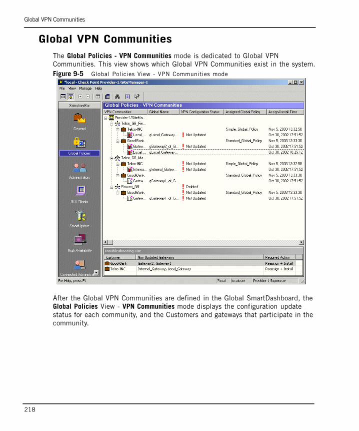
Global VPN Communities
218
Global VPN CommunitiesThe Global Policies - VPN Communities mode is dedicated to Global VPN Communities. This view shows which Global VPN Communities exist in the system.Figure 9-5 Global Policies View - VPN Communities mode
After the Global VPN Communities are defined in the Global SmartDashboard, the Global Policies View - VPN Communities mode displays the configuration update status for each community, and the Customers and gateways that participate in the community.

Administrators
Chapter 9 Monitoring in Provider-1 219
AdministratorsTo view all the administrators that have been created in the system, and the Customers for which they are responsible for, use the Administrators View - Customers per Administrator mode.Figure 9-6 Administrators View - Customers per Administrator
The Administrators View allows you to:
• Add, edit and delete an Administrator.
• Specify and edit the Administrator's password.
• Specify and edit the Administrator's Provider-1/SiteManager-1 permissions.
• Specify and edit the Administrator's Customer permissions (for various Check Point applications).
• Assign or remove an Administrator from managing a Customer's network.
Alternatively, you can view the system by looking at a list of Customers, and which Administrators are assigned to each of them, through the Administrators View - Administrators per Customers mode.

GUI Clients
220
Connected AdministratorsTo see which administrators are Active in the system at any time, use the Connected Administrators View. This view allows you determine if any questionable activity has taken place. This view also allows the Provider-1 Superuser to use mouse’s right-click and regular menus to delete an administrator’s connection.Figure 9-7 Connected Administrators View
GUI ClientsTo see which GUI Clients have been assigned for use, and to which MDSs or Customer environments they are connected, use the GUI Clients View. In this view information is displayed by default in a Customer per GUI Client hierarchy, in other words where you can see the GUI Clients and the Customers assigned to each. You can manage these entities by right-clicking on the GUI Client and selecting to assign Customers to it. This view can be toggled so that the hierarchy is reversed, in other words where you can see GUI Clients per Customer. Similarly, by right-clicking on a Customer you can select to assign GUI Clients to it.Figure 9-8 GUI Clients window - Customers per GUI Client
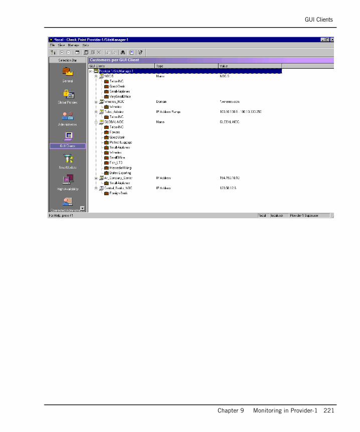
GUI Clients
Chapter 9 Monitoring in Provider-1 221

Using SmartConsole to Monitor Customer’s Network Activity
222
Using SmartConsole to Monitor Customer’s Network Activity
Setting up Log Tracking in Provider-1The Provider-1 system uses either CMAs or CLMs to gather information about Customer gateways' activities. CMAs and CLMs can gather detailed log information from VPN-1 Pro gateways, VPN-1 Edge/Embedded appliances, and many OPSEC-certified security applications. This information can then be accessed using the SmartConsole Clients.
Tracking Logs with SmartView TrackerAll administrator activity using SmartConsole Client applications, such as SmartDashboard, is logged in audit logs. These logs can be monitored using SmartView Tracker, which can dramatically reduce the time needed to troubleshoot configuration errors.
The graphical SmartView Tracker uses the logging data on the server to provide real-time visual tracking, monitoring, and accounting information for all connections including VPN remote user sessions. Administrators can perform searches or filter log records to quickly locate and track events of interest. To use SmartView Tracker, in the MDG, select a CMA, then right click and choose Launch Application > SmartView Tracker.

Tracking Logs with SmartView Tracker
Chapter 9 Monitoring in Provider-1 223
Figure 9-9 SmartView Tracker
If there is an attack or other suspicious network activity, administrators can use SmartView Tracker to temporarily or permanently terminate connections from specific IP addresses. For more information about using SmartView Tracker, see the SmartCenter Guide.
Real-Time Network Monitoring with SmartView MonitorSmartView Monitor is an easy-to-use monitoring tool that allows you to inspect network traffic and connectivity. In addition, it provides real-time information about the performance and security state of both Firewall and VPN operations.
To use SmartView Monitor, select a CMA from any view, then right click and choose Launch Application > SmartView Monitor.

Tracking Logs with SmartView Tracker
224
Figure 9-10 SmartView Monitor
If your network experiences problems such as sluggishness, loss of data or security related problems, it is important to immediately identify these phenomena. SmartView Monitor provides a real-time monitoring tool designed to help administrators find the cause of these problems, when and why they occur, and how to fix them. Use SmartView Monitor to examine traffic, requested services, and network load in the customer network. For more information, see the SmartView Monitor guide.
Check Point System Counters
SmartView Monitor uses Check Point System Counters to collect information about the status, activities, hardware and software usage of different Check Point products in real time. System Counters are used to plot graphs and to view reports of current or archived data collected by Counter Logs.

Eventia Reporter Reports
Chapter 9 Monitoring in Provider-1 225
Traffic Flow and Virtual Link Monitoring
Traffic flow can be monitored per service or network object. SmartView Monitor also enables monitoring based on a variety of parameters, for example the QoS Policy rules installed on an interface, etc. Compliance to a Service Level Agreement (SLA) can be monitored, and alerts can be generated. Traffic can be monitored between two Check Point VPN-1 Pro modules or two QoS Modules for real time analysis of bandwidth and latency.
Blocking Suspicious Connections
Suspicious Activity rules are security rules that enable the administrator to instantly block suspicious connections not restricted by the currently enforced Security Policy.
Eventia Reporter ReportsThe Eventia Reporter delivers a user-friendly solution for auditing traffic and generating detailed or summarized reports in the format of your choice (list, vertical bar, pie chart etc.) for events logged by CMA-managed gateways that are running SmartView Monitor. Eventia Reporter produces reports for these modules.
See the Eventia Reporter Guide to understand how to generate Eventia Reporter Reports.

Eventia Reporter Reports
226

227
Chapter 10High Availability
In This Chapter
Overview page 228
CMA High Availability page 229
MDS High Availability page 235
Configuration page 245

Overview
228
OverviewProvider-1/SiteManager-1 supports High Availability — a Check Point feature that ensures uninterrupted service availability in case of a computer crash. Provider-1/SiteManager-1 implements High Availability at three levels:
• The enforcement point (module) level, such as through ClusterXL.
• The CMA level: two CMAs (one Active, one Standby) are supported, as is one SmartCenter Backup Server, per Customer.
• The MDS level, through MDS synchronization.
By using ClusterXL, Customer networks are protected in the event of a gateway computer failure. Customers may choose to implement gateway clustering within their network environments, using SmartDashboard to configure the system. CMAs support cluster gateway management.
An administrator can implement fail-over gateway management for a Customer network by creating two CMAs, configured to High Availability. These CMAs regularly synchronize their databases, at a configurable interval or specified event (such as saving or installing a policy). One CMA is Active, while the other is Standby. Further High Availability can be achieved by installing a SmartCenter Backup Server, which can take over if both CMAs fail.
The MDS Manager is the point of entry to the Provider-1 system. Any Manager can serve as a point of entry: and if one fails for any reason, another can be used as an access point for system management. Managers are configurable to regularly synchronize their databases, so that if one fails, others contain updated data regarding the system. It is possible to set up MDS Container mirror sites, so that Containers are mirrored.

CMA High Availability
Chapter 10 High Availability 229
CMA High AvailabilityImplementing CMA High Availability guarantees management fail-over capability for a Customer network. At any given time, one gateway management (CMA) is Active while the other is in Standby mode. Data synchronization between the two CMAs greatly improves fault tolerance and enables the administrator to seamlessly activate a Standby CMA when required.
With High Availability, should a CMA fail for any reason, the Standby CMA can seamlessly continue operation. The High Availability scheme requires one Primary CMA and one Secondary CMA, which are housed separately, on different MDS Containers. The MDSs must have the same operating system (e.g., either both Linux or Solaris).
The two CMAs can be created at the same time, or a secondary CMA may be added at a later point. After the secondary CMA has been properly initialized and synchronized, no functional differences exist between the two CMAs. Each CMA must be on a different Container. The same Container cannot contain two CMA’s belonging to the same Customer.
It is possible to set up one Container with primary CMAs, and a second to contain all the secondary CMAs. This is called a “mirror system” and is explained later in this chapter. This can be a useful solution for a service provider, which concentrates all resources in a network operations center.
It is also possible to use a SmartCenter Backup Server that will allow a SmartCenter server to have Management HA relations with a Provider-1 Customer (which may have up to two CMAs in Management HA). Refer to “CMA Backup using SmartCenter Server” on page 232 for additional information.
It is not necessary to dedicate a Container to hold only secondary CMAs, a Container can hold a mix of primary and secondary CMAs, as long as they are for different Customers. Provider-1/SiteManager-1 provides this functional flexibility to support different setup needs. An international corporate network may need to have a mixture of management and backup capabilities that are quite different from those of a large-scale local service provider.
For example, a corporate bank with numerous branches finds it useful to have Active CMAs for local branches maintained on a Container in the area’s central branch. The Standby (High Availability) CMAs are maintained on the MDS in another area’s central branch.
By contrast, an MSP does not mix Active and Standby CMAs to support widespread distribution needs. The MSP implements a single, remote, mirror site for disaster recovery (see “MDS Mirror Site” on page 235).

CMA High Availability
230
To see how this works with two Containers, look at the example below. The Active CMA for a bank’s Chicago network is housed on the Chicago MDS. The Active CMA for the Atlanta network is housed on the Atlanta MDS. Each of the Standby CMAs, however, are housed at the other location’s MDS.Figure 10-1 CMA High Availability in an Enterprise network
To look at a more distributed example, let’s examine a medical supplies firm that has many offices, which want partial failover capabilities. They have MDSs in three branches: Kansas, Osaka, and Montenegro. Each MDS has a mix of Active and Standby CMAs. Mission critical networks have CMAs with High Availability (CMA 1,3,6), while others do not (CMA 2,4,5,7,8).

Active Versus Standby
Chapter 10 High Availability 231
Figure 10-2 CMA High Availability in an Enterprise network
Administrators make security policy changes through the Active CMA, not the Standby. CMA updates are made through the CMA SmartDashboard. If policy changes are made with the Active CMA, the Standby CMA is synchronized automatically to reflect these changes (unless configured otherwise, i.e. manually synchronized).
Active Versus StandbyAll management operations such as editing and installing the Security Policy and modifying users and objects, are done by the Active Management Server. If the Active Management Server is unavailable, and any of the aforementioned operations need to be performed, one of the Standby Management Servers should be made Active. This transition from Standby to Active should be initiated manually.
The Standby Management Servers are synchronized to the Active Management Server, and therefore, are kept up to date with all changes in the databases and Security Policy. Thus enforcement modules can fetch the Security Policy and retrieve a CRL from both the Active Management Server and the Standby Management Servers.
The frequency of the synchronization between the Standby Management Servers and the Active Management Server is set by the System Administrator. This process can be configured to take place automatically, or it can be set to occur manually.

Setting up a Mirror CMA
232
It is possible to configure the High Availability feature to synchronize automatically for each policy installation operation, on each policy save operation and on any other scheduled event. If the Standby Management Server’s data has not been synchronized with the Active Management Server, you can still use the Standby Management Server, which is updated until the moment of the last synchronization.
The terms “Active” and “Standby” are not the same as the terms “Primary CMA” and “Secondary CMA,” which have to do with the chronological order of creation. Either CMAs can be set up to be Active or Standby. Initially, the Primary CMA (the first one created) is the Active one, but later on the administrator can manually change this as needed.
Setting up a Mirror CMAWhen you add a Mirror CMA through the MDG, Provider-1/SiteManager-1 performs a series of automatic operations (no user intervention is required), as below:
1. Creates the CMA on the MDS selected. Copies the Certificate Authority (CA) files of the primary CMA to the mirror CMA.
2. Starts the mirror CMA and exchanges the activation key between the two CMAs. Then initializes SIC communication between the two CMAs.
3. Synchronizes the mirror CMA with the primary CMA. At this stage, both CMAs are running (if the primary CMA is down, the system will automatically attempt to start it).
If the operation fails at stage 2 or 3, the administrator can complete these stages manually.
CMA Backup using SmartCenter ServerSmartCenter Backup Server is able to backup a specific Provider-1 Customer CMA or a High Availability CMA as described above, and can function as an Active/Standby management. For example;
• The SmartCenter Backup Server is the Standby management and the CMA server is the Active management. When the CMA server is unavailable, the SmartCenter Backup Server can become the Active management.
• The CMA Server is the Standby management and the SmartCenter Backup Server is the Active management. When the SmartCenter Backup Server is unavailable, the CMA Server can become the Active management.

CMA Backup using SmartCenter Server
Chapter 10 High Availability 233
GUI Clients and Administrators definitions are separate for the CMAs and for the SmartCenter Backup Server.
GUI Clients and Administrators that were defined on the Provider-1 server are not automatically used on the SmartCenter Backup Server and vice versa. Figure 10-3 SmartCenter Backup Server
SmartCenter Backup Server Setup ProcedureTo perform a SmartCenter Backup Server fresh installation:
1. Perform a fresh SmartCenter server installation as a secondary SmartCenter server.
2. Use cpconfig to configure the following:
1. Select an activation key that will be used to establish secure internal communication (SIC) between the SmartCenter and CMA.
2. Define GUI Clients and Administrators.
3. In SmartDashboard connected to the Provider-1 CMA, create a network object that will represent the secondary SmartCenter Backup Server.

CMA Backup using SmartCenter Server
234
1. Select Manage > Network Objects > Check Point > New > Host
2. In the Check Point Host window, check Secondary Management Station under Check Point Products. This automatically selects Log Server as well.
4. From the object created in step 3 establish secure communication with the secondary SmartCenter Backup Server.
5. From SmartDashboard access the Policy menu, select Management High Availability and press the Synchronize button.
To setup a SmartCenter Backup Server from an existing SmartCenter server:
1. Migrate the existing SmartCenter server to the Provider-1 CMA using the tools in “Upgrading Provider-1” of the NGX R61 Upgrade Guide.
2. Perform a fresh SmartCenter server installation as a secondary SmartCenter server on an existing or new machine.
3. Using cpconfig to select an activation key that will be used to establish secure internal communication (SIC) between the CMA and SmartCenter.
4. Create a network object in the Provider-1 CMA that will represent the secondary SmartCenter Backup Server.
1. Select Manage > Network Objects > Check Point > New > Host
2. In the Check Point Host window, check Secondary Management Station under Check Point Products. This automatically selects Log Server as well.
5. From the object created in step 4 establish secure communication with the secondary SmartCenter Backup Server.
6. From SmartDashboard access the Policy menu, select Management High Availability and press the Synchronize button.

MDS High Availability
Chapter 10 High Availability 235
MDS High Availability
MDS Mirror SiteIt is possible to mirror an entire MDS, using a second MDS. For all CMAs on the first MDS Manager/Container, High Availability CMAs can be created on a second MDS Manager/Container. By default, when changes are made to the CMAs in the first Container, the system synchronizes the Active CMAs with the Standby CMAs. The two MDS Managers are automatically synchronized also. However, CMA synchronization can be set up to occur at specified events, such as every time a Customer’s policy is saved, or when it is installed onto one or more Customer modules. Figure 10-4 Mirror MDS/CMA system

MDS Managers
236
MDS ManagersMDS Managers are “mirrors” of each other. If there is more than one MDS Manager in the system, each Manager will contain all the information regarding the Provider-1/SiteManager-1 management system such as the network setup, administrator hierarchy, selected customer and network information.
MDS Manager synchronization does not mirror CMA-specific data. For example, internal domains and customer level policy rules are known only at the CMA level, so they are not synced by MDS Managers.
Interconnected, mutually redundant MDS Managers form a robust management system providing non-stop access, without the need to deploy dedicated hardware or software redundancy. For MDSs, the Active/Standby status affects only the login to the Global SmartDashboard (as opposed to the login to the MDG). MDG management activities can be performed using any of the MDS Managers. Figure 10-5 MDS Synchronization in an Enterprise network
In terms of using MDGs, all MDS Managers are simultaneously accessible and can perform Read/Write operations at all times, except for creating/revoking MDS certificates in the MDS Configuration window, which can only be done from the Active MDS. MDS information is synchronized at configurable intervals.

Setting up a New MDS and Initiating Synchronization
Chapter 10 High Availability 237
Setting up a New MDS and Initiating Synchronization
MDS Clock SynchronizationFor proper MDS synchronization, all MDSs’ system clocks must be synchronized, as the synchronization method relates to time of modification.
The time of modification is written using UTC (Universal Time Coordinated), used by MDSs’ system clocks. The administrator can synchronize MDS clocks using available synchronization utilities. Resetting regularly to compensate for clock drift is strongly recommended. Correct database synchronization requires that the MDS clocks are synchronized to the second. It is therefore recommended that MDS clocks be synchronized automatically at least once a day.
Whenever a new MDS is defined in the MDG, it must receive a certificate and communication must be established with the new MDS. The MDS also needs to be synchronized in time with the other MDSs. The MDG guides the user through the stages of performing this initial synchronization.
MDS: Active or StandbyProvider-1/SiteManager-1 MDS High Availability means that all MDS Managers are accessible at all times, in the sense that they are all equally available to an MDG as entry points to the Provider-1/SiteManager-1 system. However, only one MDS Manager at a time can be Active in the following respects:
• The administrator can log into the Global SmartDashboard with Read/Write permissions from the MDS.
• The MDS acts as the MDS Certificate Authority.
When the first MDS Manager is created, its status is automatically Active. Any further MDS Managers that are created will be Standby. Each MDS’s Active/Standby status is displayed in the High Availability View - MDS Contents Mode.
The MDS Active/Standby status can be changed, so that a different Manager can be chosen to be Active. Should the Active Manager fail for any reason, another Manager can thus be selected as the Active Manager. All other Managers will then become Standby.

The MDS Manager’s Databases
238
The MDS Manager’s DatabasesThe MDS Manager’s stored data is divided into three databases: MDS, Global Policies and ICA. The content and synchronization method of each database is described below.
MDS DatabaseThis database holds data objects describing MDSs, Customers, CMAs, modules, licenses, administrators, GUI-clients, and information about assignment of Global Policies to customers. This database is synchronized automatically between MDS Managers. MDS Containers also contain parts of this database, which is synchronized for proper operation.
The synchronization method of this database enables simultaneously opening MDGs to different MDS Managers, and performing Read and Write operations at any time from any MDG. Changes committed to the database of one MDS Manager are distributed immediately to all other MDS Managers, and to the MDGs connected to them as well.
If MDSs were disconnected from each other, it is recommended to make changes only on one of them, to avoid data collision. Once the MDSs are reconnected, they will synchronize with each other according to modification time.
Global Policies DatabaseThis database holds the global objects (network objects, services, servers, etc.) and global rules. In terms of the Global Policies database, one of the MDS Managers is Active (the first logged into), while the rest are Standby.
Some operations can only be performed on the Active MDS, such as opening a Read/Write Global SmartDashboard. It is possible to open Global SmartDashboard in read-only mode on a Standby MDS.
ICA (Internal Certificate Authority) Database for MDSsThis database holds certificates for MDSs, administrators and CRLs (certificate revocation lists). Each MDS has a certificate issued by the MDS ICA that is used for secure communication with other MDSs. This database is synchronized whenever the Global Policy database is synchronized. Only the Active MDS can issue and revoke certificates for MDSs. When a Standby MDS Manager is made Active, its ICA also becomes “Active.”
The MDS Container’s Databases
Chapter 10 High Availability 239
The MDS Container’s DatabasesThe MDS Container also stores data, including MDS and Global Policies database information, at the MDS level. Databases at the CMA level are stored separately per Customer. Customer policies, the Customer’s ICA, and CMA-specific information are stored at the CMA level.
The MDS Container does not hold the MDS ICA database. It does hold CMA ICA databases, one per Customer. If a Customer has High Availability, both CMAs share the same CMA ICA, so that they can communicate securely with the Customer’s network modules using the same certificates.
ICA (Internal Certificate Authority) Database for CMAsThis database holds certificates for the Customer’s CMA(s) and network modules. Each Customer’s network module has a certificate issued by the CMA ICA that is used for secure communication between the CMA and module, and between modules. Only the Active CMA can issue and revoke certificates for the Customer’s modules. When a Standby CMA (the High Availability CMA) is made Active, its ICA also becomes “Active.”
How Synchronization Works
MDS Database SynchronizationMDS database synchronization occurs automatically whenever an object is changed. The MDS databases are synchronized for the specific object change.
For example, if a new administrator is added to the system, all MDSs will be updated with this information. In this system, with an MDS Manager/Container and an MDS Container, the MDS database must be synchronized between the Manager/Container and Container so that they are both contain information about the Administrator’s existence.

How Synchronization Works
240
Figure 10-6 MDS database synchronization
MDS ICA Database SynchronizationIf a new MDS is added to the system, the MDS ICA must issue a certificate to the new MDS. If a new administrator is added to the system, the MDS ICA may issue a certificate to the new administrator, depending on the administrator's authentication method. The MDS ICA database is updated. If there is more than one MDS Manager in the system, the MDS Manager’s ICA databases must be synchronized to reflect these additions.
Let us say that when a new administrator is added to the system, she is issued a certificate from the MDS ICA, which she will use at MDG login to authenticate her identity.
If there is more than one MDS Manager in the system, the MDS Manager’s ICA databases are synchronized to reflect this update. But in this system, as there is only one MDS Manager (the MDS Manager/Container), there is no need for MDS ICA synchronization. The MDS Container does not hold the MDS ICA database.
Global Policies Database SynchronizationGlobal Policies data synchronization occurs either when the global policy is saved, or at another defined event (for details about synchronization settings, see “Automatic Synchronization for Global Policies Databases” on page 248). Unlike the MDS database synchronization, which is per object, the entire contents of the Global Policies database are synchronized.
For example, if a new Global Policy is defined, all MDSs will be updated with this information. In this system, containing an MDS Manager/Container and an MDS Container, the Global Policies databases are synchronized so that they both contain information about the new Global Policy.

How Synchronization Works
Chapter 10 High Availability 241
Figure 10-7 Global Policies database synchronization
CMA Database SynchronizationFor Customers with High Availability, data synchronization occurs per Customer. Each CMA pair is synchronized when a Customer policy is saved, or at another defined event (for details about synchronization settings, see “Automatic CMA Synchronization” on page 249). The entire contents of the CMA database are synchronized.
Different Customers may have different synchronization settings. This means that different Customer’s CMAs synchronize according to the specific settings for that Customer only. When information is changed or updated for a Customer, if the Customer has High Availability, both CMAs must receive the new information. For example, if a module is added to a Customer’s network, and the module receives a certificate from the Customer’s ICA, this information must be synchronized between both Customer’s CMAs. Figure 10-8 CMA database synchronization

Setting up Synchronization
242
Cross-MDS SynchronizationAll of these synchronizations take place according to individual synchronization settings or conditions, even though they may take place on the same machines.Figure 10-9 MDS and CMA level synchronizations between two MDSs
Setting up Synchronization
Using the MDG to Synchronize the MDSsProvider-1/SiteManager-1 High Availability is managed through the MDG’s High Availability View. The administrator can perform all management High Availability activities through this view, and view the status of these actions after a configurable delay.

Setting up Synchronization
Chapter 10 High Availability 243
Figure 10-10High Availability View — Customer Contents Mode
The Sync Status displays synchronization statuses for MDSs and CMAs. Every synchronization takes a certain amount of time to update the status. The default is 5 minutes. Statuses are as follows:
• Unknown — No information has been received about this CMA/MDS (see footnote 1.) synchronization status.
• Never synced — This CMA/MDS has never been synchronized with the other CMA/MDS to which the MDG is connected.
• Synchronized — This CMA/MDS (see footnote 1.) is synchronized with the other CMA/MDS to which the MDG is connected.
• Lagging — The data of this CMA/MDS (see footnote 1.) is less updated than the data of the other CMA/MDS to which the MDG is connected.
• Advanced —The data of this CMA/MDS (see footnote 1.) is more updated than the data of the other CMA/MDS to which the MDG is connected.
• Collision — The data of this CMA/MDS (see footnote 1.) conflicts with the data of the other CMA/MDS to which the MDG is connected.

Setting up Synchronization
244
Footnotes:
1. When dealing with MDS synchronization status, the status is relevant for the Global Policies database. The ICA database is synchronized automatically between MDSs when new certificates are created for administrators/MDSs/MLMs, but when the database is modified as a result from operations in Global SmartDashboard, it will be synchronized with the next Global Policies database synchronization.

Configuration
Chapter 10 High Availability 245
Configuration
Adding another MDS The following steps are described in greater detail in Chapter 3, “Provisioning the Provider-1 Environment”, in the section “Installing the MDS - Creating a Primary Manager” on page 89.
1. Synchronize the system clock of the new MDS computer with all other MDSs computers’ system clocks.
2. Run the MDS installation script to install the MDS. When you are asked if this is an MDS Manager or Container MDS, select the type of MDS you want to add.
3. If you set up an MDS Manager, when you are asked if this is the Primary MDS, answer No.
4. During the configuration phase add an MDS license, and the Activation Key (password). This Activation Key if for passing the SIC certificate to the new MDS from the primary MDS.
5. In the MDG connected to the first MDS, define a new MDS. Assign it the IP address of the Leading Interface you selected for it in the configuration phase. Send the new MDS a certificate by the Initialize Communication option. Use the same Activation Key you entered in the configuration of the new MDS.
6. You will be prompted to perform an “Initial synchronization” for this MDS. Select to do so. Your new MDS Manager is now ready. You can connect directly to it with the MDG client.
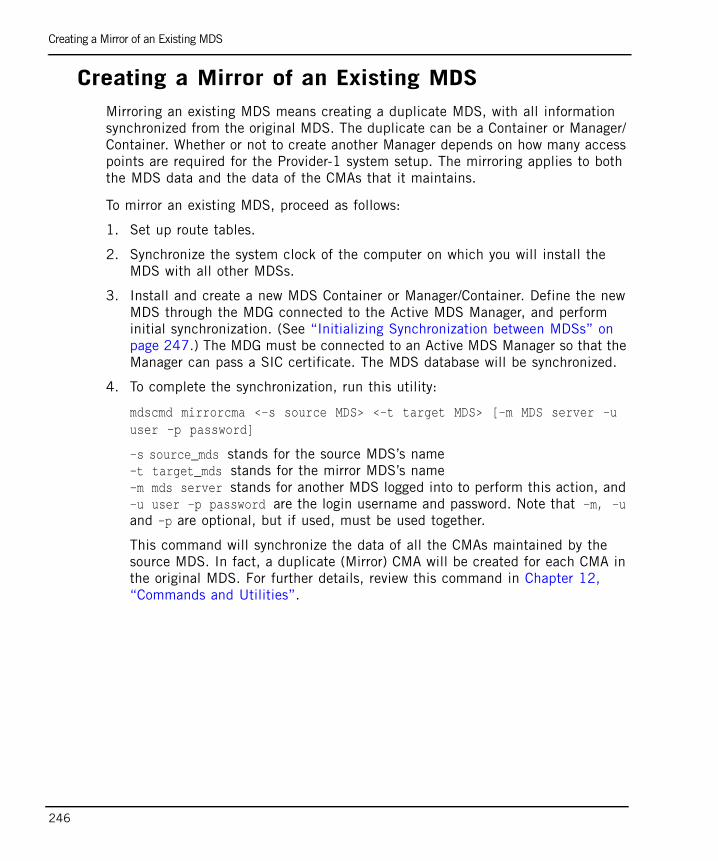
Creating a Mirror of an Existing MDS
246
Creating a Mirror of an Existing MDSMirroring an existing MDS means creating a duplicate MDS, with all information synchronized from the original MDS. The duplicate can be a Container or Manager/ Container. Whether or not to create another Manager depends on how many access points are required for the Provider-1 system setup. The mirroring applies to both the MDS data and the data of the CMAs that it maintains.
To mirror an existing MDS, proceed as follows:
1. Set up route tables.
2. Synchronize the system clock of the computer on which you will install the MDS with all other MDSs.
3. Install and create a new MDS Container or Manager/Container. Define the new MDS through the MDG connected to the Active MDS Manager, and perform initial synchronization. (See “Initializing Synchronization between MDSs” on page 247.) The MDG must be connected to an Active MDS Manager so that the Manager can pass a SIC certificate. The MDS database will be synchronized.
4. To complete the synchronization, run this utility:
mdscmd mirrorcma <-s source MDS> <-t target MDS> [-m MDS server -uuser -p password]
-s source_mds stands for the source MDS’s name-t target_mds stands for the mirror MDS’s name-m mds server stands for another MDS logged into to perform this action, and -u user -p password are the login username and password. Note that -m, -u and -p are optional, but if used, must be used together.
This command will synchronize the data of all the CMAs maintained by the source MDS. In fact, a duplicate (Mirror) CMA will be created for each CMA in the original MDS. For further details, review this command in Chapter 12, “Commands and Utilities”.

Initializing Synchronization between MDSs
Chapter 10 High Availability 247
Initializing Synchronization between MDSsThis step can be performed in the MDS Configuration window while creating the MDS. Or it can be done later after the MDS is created, through the MDG’s High Availability View, as follows:
1. Verify that the Sync Status status of the MDS whose synchronization you want to initialize is Never synced.
2. Ensure that SIC has been established between the two MDSs.
3. Right-click the MDS, then select Initialize Synchronization, or select Initialize Synchronization from the Manage menu. The Status Report window is displayed, showing whether synchronization initialization succeeded or failed.
Subsequent Synchronization for MDSsIf you have already initialized the synchronization of an MDS, but at some point the synchronization encountered problems, you can synchronize the MDS once again through the High Availability View - MDS Contents mode.
You can either select a single MDS and synchronize it with the MDS Manager you logged into; or select a group of MDSs and synchronize all of them with each other.
To Synchronize a Single MDS with an MDS Manager1. Select the MDS you want to synchronize with the MDS Manager you logged
into. Check that its Sync.Status is other than Never synced or Unknown.
2. Right-click the MDS and select Synchronize, or select Synchronize from the Manage menu.
To Synchronize a Group of MDSsChoose Select and Synchronize from the Manage menu. The Multi Domain Server Synchronization window is displayed, in which you to select which MDSs are to be synchronized.

Selecting a Different MDS to be the Active MDS
248
Selecting a Different MDS to be the Active MDSIf the Active/Standby status of the MDS Manager is Standby, you can use the Change Over command to change its this status to Active. Once you change the status there is a delay (by default 5 minutes) until the status is updated.
To Change the Active MDS1. Ensure that you are not logged into Global SmartDashboard (except in
Read-only mode).
2. Select the MDS Manager you want to make Active.
3. Select Change Over from the Manage menu.
4. The status will be changed to Active. The statuses of all other MDS Managers in the system will be Standby.
Automatic Synchronization for Global Policies Databases
The Global Policies database synchronization method is selected in the Global SmartDashboard (Policy > Global properties > Management High Availability menu).
The following options are available:
On Save - after the Save operation in the Global SmartDashboard, the database is synchronized to other MDS Managers and container MDSs as well
Scheduled - you can select a scheduled synchronization (for example, once a day at a certain time). Use local time for the scheduled event.
On Save and Scheduled can be selected simultaneously, or none of the options can be selected.
Add a Secondary CMAAdd a CMA through the MDG. A customer must have at least one CMA before a secondary CMA can be added to it. The secondary CMA must be created on a different MDS. Ensure that the primary CMA’s SmartDashboard is closed. This procedure is described in more detail in the Chapter 4, “High-Level Customer Management”, in the section “Configuration” on page 126.
To add a secondary CMA:

Automatic CMA Synchronization
Chapter 10 High Availability 249
1. In the MDG Customer View, select a customer, then select Add Customer Management Add-on/Add Customer Log Module from the Manage menu, or right-click the customer and select Add Customer Management Add-on/Add Customer Log Module.
2. You are required to complete the fields shown. Enter a name for the CMA which does not contain any spaces. Select the Container MDS on which this CMA will be maintained.
3. Next, fill in the license information.
Automatic CMA Synchronization When a mirror CMA is created, it is automatically synchronized with the primary CMA’s database. To keep these two CMAs regularly synchronized, it is recommended that you set up automatic synchronization through SmartDashboard. The synchronization method is user selectable, through SmartDashboard’s Policy > Management High Availability menu. For detailed instructions on synchronizing management stations, see the “High Availability” chapter of the SmartCenter Guide.
Synchronize ClusterXL ModulesThe Firewall synchronization feature provides the mechanism for synchronizing the states of two VPN-1 Pro modules. High Availability for VPN-1 Pro modules is described in the ClusterXL Guide. High Availability for encrypted connections is described in the VPN Guide.

Synchronize ClusterXL Modules
250

251
Chapter 11Architecture and Processes
In This Chapter
Packages in MDS Installation page 252
MDS File System page 254
Processes page 257
MDS Configuration Databases page 261
Connectivity Between Different Processes page 263
Issues Relating to Different Platforms page 266

Packages in MDS Installation
252
Packages in MDS InstallationIn This Section
Packages in Common MDS InstallationProvider-1/SiteManager-1 NGX R61 Multi-Domain Server installation consists of the following packages:
On Linux and SecurePlatform, package names contain suffix “-00”, for instance, the full name of CPsuite-R61 package for these platforms is CPsuite-R61-00.
All of these packages have pre-defined dependencies between them. Under no circumstances should these packages be manually removed.
Packages in Common MDS Installation page 252
Packages in MDS Upgrade page 253
Eventia Reporter Add-on page 253
Table 11-1 Common MDS Packages in NGX R61
Package Description
CPmds-R61 Check Point Multi-Domain Server NGX R61
CPsuite-R61 Check Point VPN-1 Pro/Express NGX R61
CPEdgecmp Check Point VPN-1 Edge Compatibility Package
CPngcmp-R61 Check Point R55 Compatibility Package for NGX R61
CPR55WCmp-R61 Check Point R55W Compatibility Package for NGX R61
Warning - Manually removing a package has negative implications on the Multi-Domain Server.

Packages in MDS Upgrade
Chapter 11 Architecture and Processes 253
Packages in MDS UpgradeWhen upgrading the entire Multi-Domain Server environment the previous installation stays untouched. This means that you can remove the new installation and return to the working environment of the previous installation, if required. In other words, after upgrading an MDS machine, both the previous version and the new version packages are installed. These packages can be seen using pkginfo command in Solaris environment, or rpm command in Linux.
Provider-1/SiteManager-1 NGX R61 MDS installations consist of somewhat different packages than those that existed previously. Compare for example Table 11-1 with Table 11-2, which lists the packages that existed in Provider-1 NG with Application Intelligence R55.
In Provider-1/SiteManager-1 NG with Application Intelligence (R54), another difference existed for Solaris installations - the package for the SofaWare SmartCenter Safe@ Connector, named SSC-4.
Eventia Reporter Add-onThe Eventia Reporter Add-on for Provider-1/SiteManager-1 doesn’t have its own package. It is installed, removed, enabled and disabled using the SVRSetup script provided with MDS installation.
Table 11-2 Packages in Provider-1 NG with Application Intelligence R55
Package Description
CPmds-R55 Check Point Multi-Domain Server NG with Application Intelligence (R55)
CPfw1-R55 Check Point VPN-1 NG with Application Intelligence (R55)
CPshrd-R55 Check Point SVN Foundation NG with Application Intelligence (R55)
CPfg1-R55 Check Point FloodGate-1 NG with Application Intelligence (R55)
CPrtm-R55 Check Point SmartView Monitor NG with Application Intelligence (R55)
CPfwbc-41 Check Point VPN-1/FireWall-1 4.1 for Backward Compatibility
CPfgbc-41 Check Point FloodGate-1 4.1 for Backward Compatibility (Solaris only)

MDS File System
254
MDS File SystemIn This Section
MDS Directories on /opt and /var File SystemsMDS Installation creates subdirectories under /opt and /var/opt directories. Following is the list of subdirectories created under /opt:
Following is the list of subdirectories created under /var/opt:
MDS Directories on /opt and /var File Systems page 254
Structure of CMA Directory Trees page 255
Check Point Registry page 256
Automatic Start of MDS Processes, Files in /etc/rc3.d, /etc/init.d page 256
Table 11-3 Subdirectories under /opt
Subdirectory Description
CPInstLog Contains installation and upgrade log files.
CPsuite-R61 Contains the installation of the CPsuite-R61 package.
CPshrd-R61 Contains information from the CPsuite-R61 package.
CPshared Exists for compatibility with previous versions.
CPEdgecmp Contains the installation of the CPEdgecmp package.
CPngcmp-R61 Contains the installation of the CPngcmp-R61 package.
CPR55WCmp-R61 Contains the installation of the CPR55WCmp-R61 package.
CPmds-R61 Contains the installation of the CPmds-R61 package.
Table 11-4 Subdirectories under /var/opt
Subdirectory Description
CPsuite-R61 Contains configuration, state and log files for Check Point VPN-1 Pro/Express management.
CPshrd-R61 Contains the configuration of Check Point SVN Foundation, a well as the registry files.
CPEdgecmp Contains configuration files for the CPEdgecmp package.

Structure of CMA Directory Trees
Chapter 11 Architecture and Processes 255
Structure of CMA Directory TreesOn Multi-Domain Container server, the CMA directories can be found under /var/opt/CPmds-R61/customers directory. For each CMA residing on the server, there is a separate directory under this path. Each CMA directory contains the following subdirectories:
CPngcmp-R61 Contains configuration files for the CPngcmp-R61 package.
CPR55WCmp-R61 Contains configuration files for the CPR55WCmp-R61 package.
CPmds-R61 Contains configuration of the Multi-Domain server, MDS-level logs and configuration/state/log files of Customer databases.
Table 11-4 Subdirectories under /var/opt
Subdirectory Description
Table 11-5 CMA Subdirectories
Subdirectory Description
CPsuite-R61 Contains the configuration, state and log files of this Customer, as well as links to the shared binaries and library files.
CPshrd-R61 Contains the configuration for the SVN Foundation for the Customer owning this CMA, as well as links to shared binaries and library files.
CPEdgecmp Contains configuration files of the CPEdgecmp package for the Customer owning this CMA, as well as links to shared binaries and library files.
CPngcmp-R61 Contains configuration files of the CPngcmp-R61 package for the Customer owning this CMA, as well as links to shared binaries and library files.
CPR55WCmp-R61 Contains configuration files of CPR55WCmp-R61 package for the Customer owning this CMA, as well as links to shared binaries and library files.

Check Point Registry
256
Check Point RegistryInformation related to the installation and versioning issues of different components that is requested by different Check Point processes, is centrally stored in a registry file.
The registry is stored in $CPDIR/registry/HKLM_registry.data (where the value of CPDIR environment variable is different whether you are in the MDS environment or whether you are in different CMA environments. This means that there are separate registry files for the MDS and for the CMAs.
Automatic Start of MDS Processes, Files in /etc/rc3.d, /etc/init.d
The script for the automatic start of MDS processes upon boot can be found in /etc/init.d. The name of the file is firewall1. A link to this file appears in /etc/rc3.d directory under the name S95firewall1.

Processes
Chapter 11 Architecture and Processes 257
ProcessesIn This Section
Environment VariablesDifferent Multi-Domain server processes require standard environment variables to be defined. The variables have the following functionality, they:
• Point to the installation directories of different components.
• Contain management IP addresses.
• Hold data important for correct initialization and operation of the processes.
Additionally, specific environment variables control certain parameters of different functions of Multi-Domain server.
MDS installation contains shell scripts for C-Shell and for Bourne Shell, that define the necessary environment variables:
• The C-Shell version is /opt/CPshrd-R61/tmp/.CPprofile.csh
• The Bourne Shell version is /opt/CPshrd-R61/tmp/.CPprofile.sh
Sourcing these files (or in other words, using “source” command in C-Shell or “.” command in Bourne Shell) will define the environment necessary for the MDS processes to run.
Environment Variables page 257
MDS Level Processes page 259
CMA Level Processes page 260

Environment Variables
258
Standard Check Point Environment Variables
Environment Variables Defining Parameters/Thresholds for Different MDS functions
Logging Cache Size
By default, the CMA reserves 1MB memory for log caching on the Management. In very intensive logging systems it is possible to raise the cache size. This requires more memory, but boosts the performance. To change the cache size, set:
LOGDB_CACHE_SIZE variable to the desired size in Kilobytes. For example, to set the cache to 4MB enter:
setenv LOGDB_CACHE_SIZE 4096 (in C-Shell syntax)
Additional environment variables controlling such mechanism as statuses collection mechanism (like MSP_SPACING_REG_CMAS_FOR_STATUSES) or connection retries (like MSP_RETRY_INTERVAL) are described later in this chapter.
Table 11-6 Standard Check Point Environment Variables
Variable Description
FWDIR points to the location of Check Point VPN-1 Pro binary/configuration/library files. • In the MDS environment, this environment variable is
equal to MDSDIR• In CMA environment, it contains
/opt/CPmds-R61/customers/<CMA Name>/CPsuite-R61/fw1
CPDIR points to the location of Check Point SVN Foundation binary/configuration/library files. It points to different directories in MDS and CMA environments.
MDSDIR points to the location of the MDS installation. In Provider-1/SiteManager-1 NGX R61 - /opt/CPmds-R61
SUROOT points to the location of SmartUpdate packages

MDS Level Processes
Chapter 11 Architecture and Processes 259
MDS Level ProcessesEach MDS Level process has one instance on every MDS/MLM machine, when the MDS/MLM server is running. The following processes run on the MDS level:
For proper operation of the Multi-Domain Server all four processes must be running, unless dealing with configurations where cpca shouldn’t be running.
Table 11-7 MDS Level Processes
Process Description
cpd SVN Foundation infrastructure process.
cpca The Certificate Authority manager process. This process doesn’t run on Log Managers or Container MDSs.
fwd Audit Log Server process.
fwm mds MDS main process.

CMA Level Processes
260
CMA Level ProcessesEach one of these processes has a separate instance for every running CMA. The following processes run on the CMA level:
For proper operation of the CMA, at least cpd, cpca, fwd and fwm must be running, unless dealing with configurations where cpca shouldn’t be running. Other processes are required only for CMAs using specific functionality for which these processes are responsible.
Table 11-8 MDS Level Processes
Process Description
cpd SVN Foundation infrastructure process.
cpca The Certificate Authority manager process. This process doesn’t run on Log Managers and Container MDSs.
fwd Log Server process.
fwm SmartCenter server main process.
status_proxy Status collection of ROBO gateways. This process runs only on CMAs that were enabled for Large Scale Management.
sms Manages communication (status collection, logs collection, policy update, configuration update) with VPN-1 Edge/Embedded gateways. This process runs only on CMAs that manage VPN-1 Edge devices.

MDS Configuration Databases
Chapter 11 Architecture and Processes 261
MDS Configuration DatabasesThe Multi-Domain Server environment contains a number of configuration databases, as opposed to a single SmartCenter server, that contains only one.
Each Multi-Domain Server contains:
• one Global Database (located in /var/opt/CPmds-R61/conf directory)
• one MDS Database (located in /var/opt/CPmds-R61/conf/mdsdb directory)
• a number of CMA databases (on Multi-Domain Server Containers only).
Each CMA database is located in /var/opt/CPmds-R61/customers/<CMA Name>/CPsuite-R61/fw1/conf directory.
In This Section
Global Policy DatabaseThis database contains the definitions of global objects and global Security Policies. It can be viewed and edited using Global SmartDashboard client.
When the Assign Global Policy operation is invoked, the objects and policies defined in Global Policy database are copied to CMA databases, where they can be seen and used by SmartDashboard. These objects are editable only from Global SmartDashboard, CMA databases will contain read-only copies.
MDS DatabaseThis database contains two kinds of objects:
• MDS-level management objects – objects like administrators, customers, MDSs and CMAs. These objects are defined either using the Multi-Domain GUI or the MDS Command Line utilities.
• CMA-level Check Point objects – in order to display all customers’ network objects in Multi-Domain GUI, these are centrally collected in MDS Database. Each time the object is updated in SmartDashboard, the changes are automatically updated in MDS Database as well.
Global Policy Database page 261
MDS Database page 261
MDS Connection to CMAs page 263

CMA Database
262
CMA DatabaseThis database contains:
• Definitions of objects and policies created and edited by SmartDashboard, when connecting to the CMA.
• Global Objects (in read-only mode) copied by the Assign Global Policy operation.
• ROBO Gateways definitions made by SmartLSM.
Different CMAs residing on the same MDS have different separate databases.

Connectivity Between Different Processes
Chapter 11 Architecture and Processes 263
Connectivity Between Different ProcessesIn This Section
MDS Connection to CMAsThe main MDS process (fwm mds) looks for CMAs which are up and can be reached, but with which it has no CPMI connections. This connection is used for collecting statuses on the CMA and its Modules, and for receiving changes in objects that are relevant to the MDS/MDG system.
Normally, a special task wakes up every 120 seconds and searches for “CMA connection candidates”. If the task has found connection candidates previously, then by default it wakes up after only 90 seconds. This shorter interval boosts CMAs connections upon MDS startup.
You can change the values of the default intervals:
• To change the CMA connection candidates search interval, set the MSP_RETRY_INTERVAL variable to the desired number of seconds.
• To change the status collection interval, set the MSP_RETRY_INIT_INTERVALvariable to the desired number of seconds.
By default this task attempts to reconnect the MDS to no more than five CMAs per iteration. So, a system with 50 CMAs requires 10 iteration (of 90 seconds each, by default), so connecting to all the CMAs could take up to 15 minutes.
MDS Connection to CMAs page 263
Status Collection page 264
Collection of Changes in Objects page 264
Connection Between MDSs page 265
Large Scale Management Processes page 265
VPN-1 Edge Processes page 265
Reporting Server Processes page 265
High Availability Scenarios page 266
Note - Changing these values (especially MSP_RETRY_INIT_INTERVAL) makes the MDS-CMA connections faster during MDS startup, but may overload the connection if the value is set too low.

Status Collection
264
To change the maximum number of CMAs to which the MDS can connect per cycle, set the MSP_RETRY_INIT_INTERVAL variable to the desired value.
Status CollectionStatus collection begins when an MDG connects to a Manager. The MDS sends all CMAs a request to start collecting statuses. The MDS contacts the CMAs one by one, spacing these requests by one second, thus preventing the MDS load from peaking when multiple statuses arrive. You can change this default spacing and set the required spacing in milliseconds, with the environment variable MSP_SPACING_REG_CMAS_FOR_STATUSES.
Changing the Status Collection CycleThe default status collection cycle takes 300 seconds, i.e. each system entity is monitored once every 5 minutes. This value can be changed per MDS in the MDG as follows:
1. In the General View, display the MDS Contents Mode. Choose and double click an MDS. The Configure Multi Domain Server - General window opens.
2. Under Status Checking Interval, specify the desired number of seconds in the Set to field (this value is saved in the $MDSDIR/tmp/status_interval.dat file).
Once the Status Checking Interval is set in the MDG, it is effective immediately, with no need to restart the MDS. The higher you raise this value, the longer it takes to detect a change in a Module’s status.
Collection of Changes in ObjectsCheck Point objects defined in CMA databases are copied to the MDS database and presented in the Network Objects view of the MDG. Every time one of these objects is updated by SmartDashboard that is connected to the customer’s Active CMA, this change is immediately propagated to the MDS database of the MDS hosting the Active CMA. From there it is distributed to the other MDSs participating in the High Availability environment.
Note - Raising this value makes the MDS connect to all CMAs faster during startup, but may overload if it is set too low.

Connection Between MDSs
Chapter 11 Architecture and Processes 265
Connection Between MDSsWhenever the MDS/MLM servers are connected in High Availability environment they keep a constant network connection open between them. This connection is used to distribute:
• The statuses of CMAs and gateways between the MDS Containers.
• The status of administrators connected to MDS Managers.
• Latest updates of the objects propagated from CMAs.
Large Scale Management ProcessesThe Status Proxy process runs for each CMA that is enabled for Large Scale Management, and is constantly connected to the CMA to which it belongs. This process, amongst other functions, updates the CMA configuration database with such details as the last known IP address of the Dynamic IP address ROBO gateway, as well as, the gateway status.
VPN-1 Edge ProcessesThe SMS process runs for each CMA that manages VPN-1 Edge devices, and is constantly connected to the CMA to which it belongs. The VPN-1 Edge devices can be created either using SmartDashboard or using SmartLSM (where they are defined as VPN-1 Edge ROBO Gateways).
Reporting Server ProcessesWhen the Eventia Reporter Add-on for Provider-1/SiteManager-1 one is used, the Eventia Reporter Server maintains a connection to the MDS. Whenever reports are generated, another component called Eventia Reporter Generator opens a connection to the MDS as well.

Issues Relating to Different Platforms
266
Issues Relating to Different PlatformsProvider-1/SiteManager-1 NGX R61 Multi-Domain Server is supported on the following platforms:
• Sun Solaris
• RedHat Enterprise Linux 3.0
• Check Point SecurePlatform
In This Section
High Availability ScenariosWhen creating High Availability environments with:
• a number of Multi-Domain Managers/Containers
• a number of MLMs
All Provider-1 Multi-Domain Servers (MDSs) connected to a single environment should run on the same platform (i.e. either ALL of these MDSs should be installed on Solaris, RedHat Enterprise Linux or on SecurePlatform).
While all MDSs need to run on the same platform, the MDSs can manage enforcement points which run on different platforms without any problems.
High Availability Scenarios page 266
Migration Between Platforms page 267

Migration Between Platforms
Chapter 11 Architecture and Processes 267
Migration Between PlatformsUse the existing Provider-1 migration tools to move configuration databases (such as the Global Policies databases or the CMA databases) between different Provider-1/ SiteManager-1 platforms:
Table 11-9
Action Use Script/Command Comment
Migrate the Global Policies Database
migrate_global_policies script
Run this script without any parameters in order to see its usage. The files required before executing this script are specified in the script's usage. The specified files should be copied manually to the destination MDS.
Migrate complete CMA databases from one MDS machine to another.
migrate_assist script This script retrieves all of the required files for the migration of the CMA, including its configuration database and log files
Migrate the CMA into the destination environment.
Use any one of:• Import Customer
Management Add-on command from the MDG
• cma_migrate script• mdscmd migratecma
utility

Migration Between Platforms
268

269
Chapter 12Commands and Utilities cma_migrate
Description This utility is used to migrate a source database from a SmartCenter server (Management) or from another CMA. The utility supports porting from a wide range of source databases including NG FP1-3, as well as NG with Application Intelligence and NGX. The source database can be in Unix or Windows format. The cma_migrate utility can be accessed from the MDG by right clicking a CMA and selecting Import Customer Management Add-on from the menu. It is also available within the mdscmd utility. However, the most detailed output is available when using the cma_migrate command directly via the command line.The source database’s subdirectories to be migrated are conf, database and log. If you are migrating an NG- or NGX-type source database, the CPshared conf and database directories should be put inside the <oldsource database directory path>. They should be renamed conf.cpdir and database.cpdir (respectively), to avoid overwriting the FWDIR conf and database directories.
Usage cma_migrate <source database directory path> <target CMA FWDIRdirectory>

270
Syntax
Further Info. The first argument <source database directory path> specifies a path on the local MDS machine, where the data of the source database resides.
Before running cma_migrate, ensure that the source database directory structure is built according to the specifications in the table below:
1. You can use migrate_assist to put all relevant source database files into a directory, which can be either the source directory or built manually.
2. Set the structure under the source database directory to:
Argument Description
source database directorypath
The root of the original source database directory; the FWDIRdirectory, or a copy of it.
target CMA FWDIR directory The directory of the CMA we are migrating into. The target CMA cannot ever have been started before running cma_migrate. There is no need to stop the MDS before running cma_migrate
Table 12-1 Source Database Directory Structure
directory contents
conf This directory contains the information that resides under $FWDIR/conf of the source database.
database This directory contains the information that resides under $FWDIR/database of the source database.

Chapter 12 Commands and Utilities 271
Comments Administrators and GUI Client definitions are not ported by the migrate process. You must define them afterwards.
Communication between imported NG SmartCenter server/CMA and NG Modules should continue to work smoothly after the porting (the Internal Certificate Authority and certificate are ported in the process).
Example cma_migrate /tmp/orig_mgmt_dir/opt/CPmds-R61/customers/cma1/CPsuite-R61/fw1
Further Info. When migrating a management database which contains a gateway object that takes part in a VPN tunnel with an externally managed third-party gateway, an issue with the IKE certificates arises. After migration, when such a gateway presents its IKE certificate to its peer, the peer gateway uses the FQDN of the certificate to retrieve the host name and IP address of the Certificate Authority that issued the certificate. If the IKE certificate was issued by a Check Point Internal CA, the FQDN will contain the host name of the original management. In this case, the peer gateway will try to contact the original management for the CRL information, and failing to do so will not accept the certificate.
There are two ways to resolve this issue:
• Update the DNS server on the peer side to resolve the host name of the original management to the IP address of the relevant CMA.
• Revoke the IKE certificate for the gateway(s) and create a new one. The new certificate will contain the FQDN of the CMA.
log This directory contains the information that resides under $FWDIR/log of the source database or empty if you do not wish to maintain the logs.
conf.cpdir This directory is required when the source database is NG FP1 or higher. It contains the information that resides under $CPDIR/conf of the source database.
database.cpdir This directory is required when the source database is NG FP1 or higher. It contains the information that resides under $CPDIR/databaseof the source database.
Table 12-1 Source Database Directory Structure
directory contents
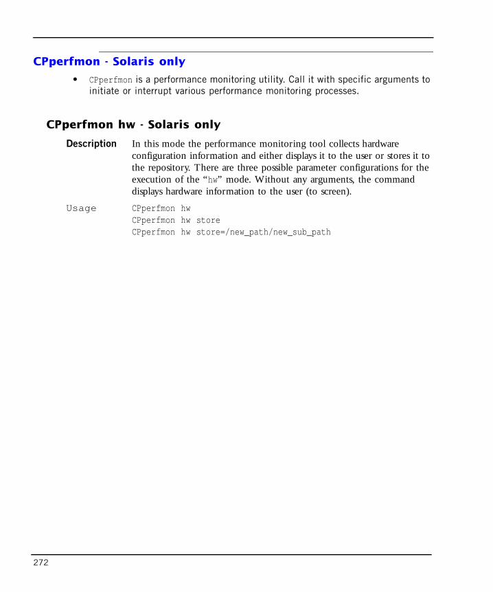
272
CPperfmon - Solaris only
• CPperfmon is a performance monitoring utility. Call it with specific arguments to initiate or interrupt various performance monitoring processes.
CPperfmon hw - Solaris only
Description In this mode the performance monitoring tool collects hardware configuration information and either displays it to the user or stores it to the repository. There are three possible parameter configurations for the execution of the “hw” mode. Without any arguments, the command displays hardware information to the user (to screen).
Usage CPperfmon hwCPperfmon hw storeCPperfmon hw store=/new_path/new_sub_path

Chapter 12 Commands and Utilities 273
Syntax
Further Info. To list system swap configuration, run:/usr/sbin/swap -l To view swap status, run:/usr/sbin/swap -s
Output Following is a sample output:
Argument Description
store Stores the collected hardware information in the default repository ($MDSDIR/log/pmrepository).The generated file name contains a timestamp, and its extension is .hardware. For instance, the file 0207111112.hardware was generated at 07/11/2002 (DD/MM/YYYY) at 11:11 (local time). Using this convention the user can “record” the changes in the hardware configuration by executing “CPperfmon hw store” command after every change.
store=/new_path/new_sub_path If the intended repository directory is different from the default one, the argument “store=/new_path/new_sub_path” should be added. The default repository base path is $MDSDIR/log, under which the performance monitor creates “pmrepository” subdirectory where it stores all of the data files.

274
CPperfmon procmem - Solaris only
Description Use the performance monitoring tool in this mode to schedule MDS processes memory monitoring. This mode consists of periodic sampling of address space maps of all running MDS and CMA processes. The user must provide sampling frequency (number of samples per single day). When scheduling sampling process, CPperfmon creates crontab entries with equal gap between them, i.e. if the requested frequency is twice a day, then two executions will be scheduled, one at 24:00 and one at 12:00. Address space maps sampling process (when initiated by cron) iterates through all of the defined CMAs and collects information.
System Configuration: Sun Microsystems sun4u Sun Ultra 5/10UPA/PCI (UltraSPARC-IIi 360MHz)System clock frequency: 90 MHzMemory size: 256 Megabytes========================= CPUs =========================
Run Ecache CPU CPUBrd CPU Module MHz MB Impl. Mask--- --- ------- ----- ------ ------ ----0 0 0 360 0.2 12 9.1
========================= IO Cards =========================Bus# Freq
Brd Type MHz Slot Name Model--- ---- ---- ---- ------------------------------------------------------0 PCI-1 33 1 ebus0 PCI-1 33 1 network-SUNW,hme0 PCI-1 33 2 SUNW,m64B ATY,GT-C0 PCI-1 33 3 ide-pci1095,646
No failures found in System===========================swapfile dev swaplo blocks free/dev/dsk/c0t0d0s1 136,9 16 1049312 740912total: 204864k bytes allocated + 14664k reserved = 219528k used,483560k available

Chapter 12 Commands and Utilities 275
Usage CPperfmon procmem <frequency>CPperfmon procmem <frequency> store= /new_path/new_sub_pathCPperfmon procmem off
Syntax
Example CPperfmon procmem 4 store=/tmp/mdsmon
Schedule MDS processes memory monitoring to run 4 times a day and store the results in /tmp/mdsmon/pmrepository.
CPperfmon monitor - Solaris only
Description Use the performance monitoring tool in this mode to schedule MDS processes memory monitoring. This mode consists of periodic sampling of system virtual memory statistics, system paging activity, Active processes statistics and connected clients statistics. Parameters which change frequently are sampled every 30 seconds, while other parameters are sampled every 30 minutes.
Usage CPperfmon monitor <duration>CPperfmon monitor <duration> store=/new_path/new_sub_pathCPperfmon monitor off
Argument Description
frequency For continuous monitoring, specify how often to store data.
store Store to the repository. If the intended repository directory is different from the default one, the argument “store=/new_path/new_sub_path” should be added. The default repository base path is $MDSDIR/log, under which the performance monitor creates “pmrepository” subdirectory where it stores all of the data files.
off De-schedules all of the scheduled periodic tasks.

276
Syntax
Example CPperfmon monitor 3Schedule system performance monitoring to run for 3 hours and use the default repository directory.
CPperfmon mdsconfig - Solaris only
Description Collects statistics and information about the user’s MDS and CMA databases. The information is either displayed to screen or stored in the repository. The user can record the changes in various configuration databases by occasionally executing the “CPperfmon mdsconfig store” command.
Usage CPperfmon mdsconfig CPperfmon mdsconfig storeCPperfmon mdsconfig store=/new_path/new_sub_path
Argument Description
duration Duration of monitoring.
monitor off De-schedules all of the scheduled monitoring processes. Removes crontab entries for low frequency processes, terminates high frequency monitoring processes.
store Store to the repository. If the intended repository directory is different from the default one, the argument “store=/new_path/new_sub_path” should be added. The default repository base path is $MDSDIR/log, under which the performance monitor creates “pmrepository” subdirectory where it stores all of the data files.

Chapter 12 Commands and Utilities 277
Syntax
Further Info. Collected parameters are:
• Size of CMA’s objects_5_0.C file.
• Size of CMA’s rulebases_5_0.fws file.
• Number of network objects in CMA’s objects_5_0.C file.
• Number of gateways with firewall installed among the defined network objects.
• Number of rulebases and number of rules in every rule base.
Output Following is a sample output:
Argument Description
store Path of the CPPerfmon repository. The default repository base path is $MDSDIR/log, under which the performance monitor creates “pmrepository” subdirectory where it stores all of the data files.
store=/new_path/new_sub_path Stores the collected databases information in the specified repository (creates a pmrepository subdirectory if necessary). The generated file name contains a timestamp, and has extension .mdsconf. For example, the file 0207111112.mdsconf was generated at 07/11/2002 (DD/MM/YYYY) at 11:11 (local time).
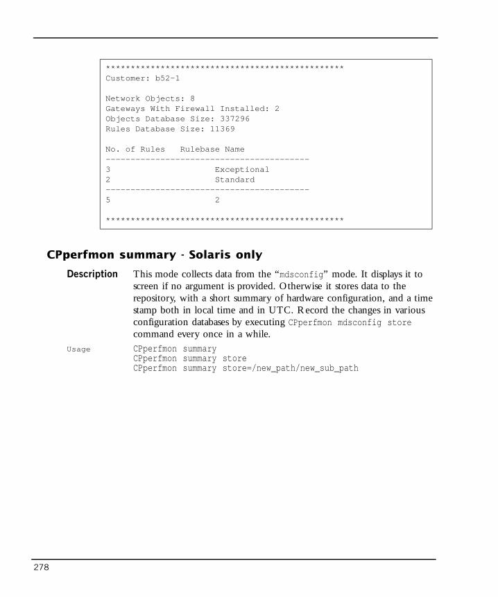
278
CPperfmon summary - Solaris only
Description This mode collects data from the “mdsconfig” mode. It displays it to screen if no argument is provided. Otherwise it stores data to the repository, with a short summary of hardware configuration, and a time stamp both in local time and in UTC. Record the changes in various configuration databases by executing CPperfmon mdsconfig store command every once in a while.
Usage CPperfmon summaryCPperfmon summary store CPperfmon summary store=/new_path/new_sub_path
************************************************Customer: b52-1
Network Objects: 8Gateways With Firewall Installed: 2Objects Database Size: 337296Rules Database Size: 11369
No. of Rules Rulebase Name-----------------------------------------3 Exceptional2 Standard-----------------------------------------5 2
************************************************

Chapter 12 Commands and Utilities 279
Syntax
Output Following is a sample output:
CPperfmon off - Solaris only
Description Use this utility to de-schedule all of the currently scheduled monitoring processes. It is equivalent to calling CPperfmon monitor off and CPperfmon procmem off together.
CPperfPack
Description This utility is used to package the performance monitor repository into single compressed file in order to send it to Check Point technical personnel.
Argument Description
store Path to the repository file. The default repository base path is $MDSDIR/log, under which the performance monitor creates “pmrepository” subdirectory where it stores all of the data files.
store=/new_path/new_sub_path Stores the collected databases information in the specified repository (creates the pmrepository subdirectory when necessary). The generated file name contains a timestamp and extension .mdsconf.
Date: Thu Jul 11 15:12:31 IDT 2002GMT Date: Thu Jul 11 12:12:31 GMT 2002Sun Microsystems sun4u Sun Ultra 5/10 UPA/PCI (UltraSPARC-IIi360MHz 256 Megabytes/dev/dsk/c0t0d0s1 136,9 16 1049312 741040
CMAName
RulebaseSize
ObjectsSize
NetworkObjects
Gateways Rules Rulebases
b52-1b52-2
1136920
337296317520
85
20
50
20

280
Usage CPperfPack [store=<your store>] [target=<your target>]
Syntax
Example CPperfPack storestore=$MDSDIR/log and saves the compressed file in $MDSDIR/tmp.
cpmiquerybin
Description cpmiquerybin utility is the binary core of the Database Query Tool.(For the Database Query Tool, see “mdsquerydb” on page 298.)This command-line CPMI client connects to the specified database, executes a query and displays results as either a collection of FW-1 Sets or tab-delimitered list of requested fields from each retrieved object. The target database of the query tool depends on the environment settings of the shell being used by the user. Whenever the user desires to access one of MDS databases, he/she should execute the mdsenv command, in order to define the environment variables
Argument Description
store Path to the repository file. The default repository base path is $MDSDIR/log.
target CPperfPack compresses the performance monitor repository and saves it in .tar.gz file in the target directory ($MDSDIR/tmp unless specified otherwise). The extension is “.tar.gz”. Example: the file CPperfMon0207111718.tar.gz was generated at 07/11/2002(DD/MM/YYYY) at 17:18 (local time). If the performance monitor repository does not reside in the default path ($MDSDIR/log) the user must provide base path of the repository (the path containing the pmrepository directory).
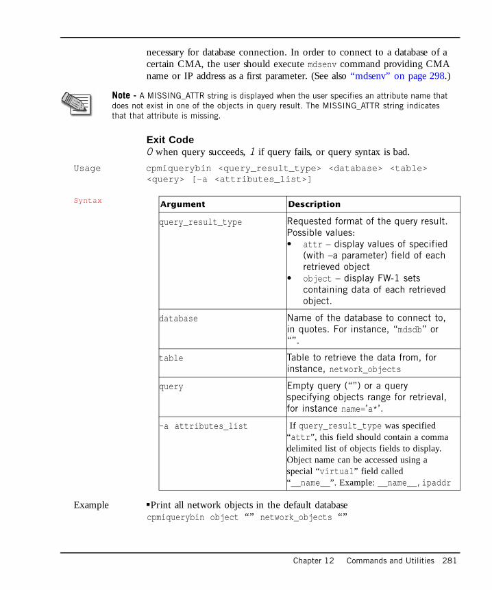
Chapter 12 Commands and Utilities 281
necessary for database connection. In order to connect to a database of a certain CMA, the user should execute mdsenv command providing CMA name or IP address as a first parameter. (See also “mdsenv” on page 298.)
Exit Code0 when query succeeds, 1 if query fails, or query syntax is bad.
Usage cpmiquerybin <query_result_type> <database> <table><query> [-a <attributes_list>]
Syntax
Example !Print all network objects in the default database cpmiquerybin object “” network_objects “”
Note - A MISSING_ATTR string is displayed when the user specifies an attribute name that does not exist in one of the objects in query result. The MISSING_ATTR string indicates that that attribute is missing.
Argument Description
query_result_type Requested format of the query result. Possible values:• attr – display values of specified
(with –a parameter) field of each retrieved object
• object – display FW-1 sets containing data of each retrieved object.
database Name of the database to connect to, in quotes. For instance, “mdsdb” or “”.
table Table to retrieve the data from, for instance, network_objects
query Empty query (“”) or a query specifying objects range for retrieval, for instance name=’a*’.
-a attributes_list If query_result_type was specified “attr”, this field should contain a comma delimited list of objects fields to display. Object name can be accessed using a special “virtual” field called “__name__”. Example: __name__,ipaddr
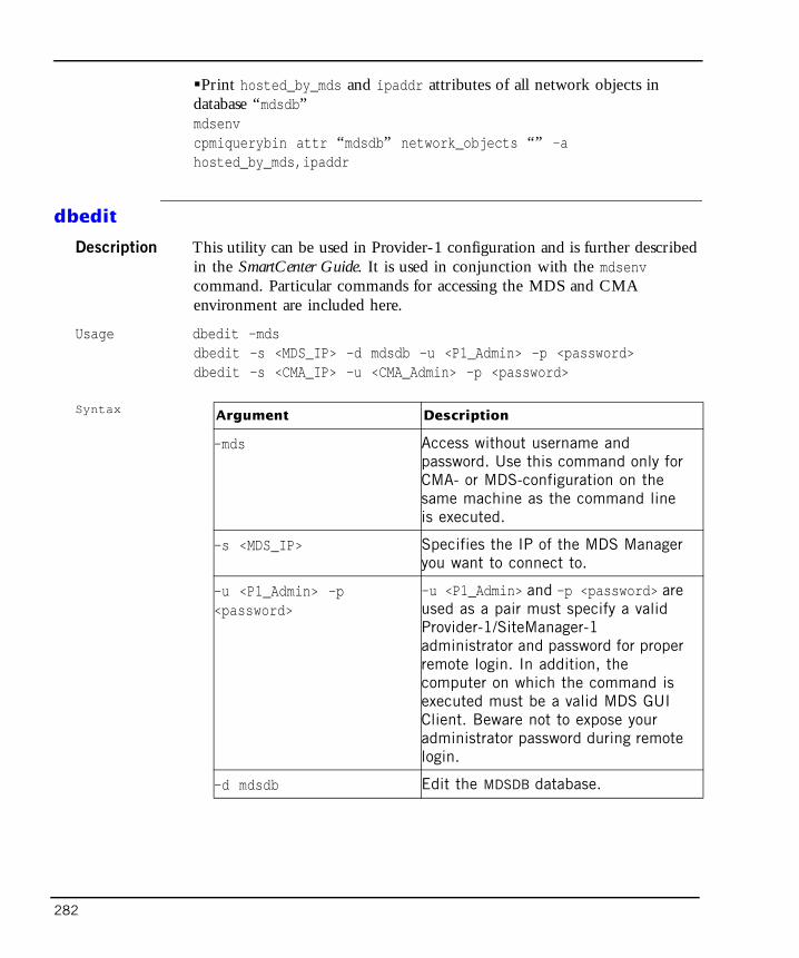
282
!Print hosted_by_mds and ipaddr attributes of all network objects in database “mdsdb” mdsenvcpmiquerybin attr “mdsdb” network_objects “” -ahosted_by_mds,ipaddr
dbedit
Description This utility can be used in Provider-1 configuration and is further described in the SmartCenter Guide. It is used in conjunction with the mdsenv command. Particular commands for accessing the MDS and CMA environment are included here.
Usage dbedit –mdsdbedit –s <MDS_IP> –d mdsdb -u <P1_Admin> -p <password>dbedit –s <CMA_IP> -u <CMA_Admin> -p <password>
Syntax Argument Description
–mds Access without username and password. Use this command only for CMA- or MDS-configuration on the same machine as the command line is executed.
–s <MDS_IP> Specifies the IP of the MDS Manager you want to connect to.
-u <P1_Admin> -p<password>
-u <P1_Admin> and -p <password> are used as a pair must specify a valid Provider-1/SiteManager-1 administrator and password for proper remote login. In addition, the computer on which the command is executed must be a valid MDS GUI Client. Beware not to expose your administrator password during remote login.
–d mdsdb Edit the MDSDB database.

Chapter 12 Commands and Utilities 283
Example To edit the database that resides on the MDS Global database, use the following commands: mdsenvdbedit –mds
To edit the database that resides on the MDS MDSDB database, use the following commands:mdsenvdbedit –mds –d mdsdb
To edit the CMA database, use the following command:mdsenv CMA_Flowerdbedit 10.10.10.10 -mds
where 10.10.10.10 is the CMA IP.
To use dbedit on a remote MDS/CMA the computer that you are running the dbedit on must be defined as an authorized GUI Client of the MDS/CMA. The user must be a Provider-1/SiteManager-1 administrator and provide a username and password: dbedit –s 10.10.10.10 -u CANDACE -p ****
where 10.10.10.10 is the MDS or CMA IP, and **** is a password.
To edit the remote MDS MDSDB database:
dbedit –s 10.10.9.1 –d mdsdb -u ROGER -p ****
where 10.10.9.1 is the MDS IP, ROGER is an administrator and **** is a password.
To edit the remote CMA database: dbedit –s 10.10.19.1 -u SAMANTHA -p ****
where 10.10.19.1 is the CMA IP, SAMANTHA is an administrator and **** is a password.
mcd bin | scripts | conf
Description This command provides a quick directory change to $FWDIR/<param>.
Example mdsenv MyCma1mcd confBrings you to: /opt/CPmds-R61/customers/MyCma1/CPsuite-R61/fw1/conf.

284
mds_backup
Description This utility stores binaries and data from your MDS installation. Runs the gtar command on the root directories of data and binaries. Any extra information located under these directories is backed up except from files that are specified in mds_exclude.dat file. The collected information is wrapped in a single zipped tar file. The name of the created backup file is constructed by the date and time of the backup, followed by the extension .mdsbk.tgz. For example: 13Sep2002-141437.mdsbk.tgz.
Usage mds_backup [-g -b {-d <target dir name>} -v -h]
Syntax
Comments When using the -g or -b options, make sure that no GUI clients or Eventia Reporter servers are connected. Otherwise, the backup may contain inconsistencies due to database changes made during the backup process.
It is important not to run mds_backup from one of the directories that will be backed up. For example, when backing up a NGX MDS, do not run mds_backup from /opt/CPmds-R61 since it is a circular reference (zipping the directory you need to write into).
Active log files are not backed up, in order to avoid read-during-write inconsistencies. It is recommended to perform a log switch prior to the backup procedure.
Argument Description
-g Execute command without asking whether to disconnect GUI clients.
-b Batch mode - execute command without asking anything (-g is implied).
-d Specify a directory to which to write the backup file. When not specified, the backup directory is the current directory. Backing up to a directory within the Check Point directory tree is not permitted.
-v Verbose mode - list all files to be backed up, but do not perform the backup operation.
-h Help - display this help

Chapter 12 Commands and Utilities 285
Further Info. The MDS configuration can be backed up without backing up the log files. Such a backup will usually be significantly smaller in size than a full backup with logs. To backup without log files, add the following line to the file $MDSDIR/conf/mds_exclude.dat:
log/*
mds_restore
Description Restores a MDS that was previously backed up with mds_backup. For correct operation, mds_restore should be restored onto a clean MDS installation.
Usage mds_restore <backup file>
mds_user_expdate
Description This command is used to modify the expiration date of the users defined in the CMAs.
Usage mds_user_expdate
Further Info. After entering the command mds_user_expdate, you are required to choose between two modes:
• Run on all CMAs located on the MDS where the command is executed.
• Run on a specific CMA.
After selecting the run method, specify the expiration date in the following format: <dd-mmm-yyyy>, e.g., 24-Feb-2003.
Comments Make sure to disconnect any GUI client before running this utility so that the changes made by the command will not be overwritten by the client. This utility can work only on Active CMAs. After running this utility, you will need to manually synchronize your CMAs.
mdscmd
Description This command is used to execute different commands on the MDS system. It connects to an MDS Manager as a CPMI client and causes it to execute one of the specified commands described below. Connection parameters [-m

286
MDS server -u user -p password] are required in order to log into a remote MDS manager. If these arguments are omitted, mdscmd connects to the local machine. As the command is a CPMI client, it has an audit log.
Usage mdscmd <sub command and sub command parameters> [-m MDS server -uuser -p password]mdscmd help
Syntax
mdscmd addcustomer
Description This command is used to create a Customer, locally or remotely. If run remotely, add login details. A first CMA can be created at the same time using this command.
Usage mdscmd addcustomer <customerName> [-n cma_name] [-i IP] [-ttarget_mds] [-m mds -u user -p password]
Argument Description
-m MDS server For remote login; specifies the name or IP address of the MDS Manager you want to connect to.
-u user -p password
Used as a pair, they must specify a valid Superuser administrator and password for remote login. In addition, the computer on which the command is executed must be a valid MDS GUI Client. Beware not to expose your administrator password during remote login.
help Print the usage of an mdscmd command and a list of examples.

Chapter 12 Commands and Utilities 287
Syntax
Example Add a new Customer named BestCustomer without a CMA:mdscmd addcustomer BestCustomerAdd a new Customer named BestCustomer with a CMA named BestCustomerCma, using the Virtual IP address 4.4.4.4:mdscmd addcustomer BestCustomer -n BestCustomerCma -i 4.4.4.4
Argument Description
CustomerName Specifies the name of the Customer to add.
-n cma_name A first CMA is created when the customer is created, using the name you provide (cma_name).
-m mds Specifies the name or IP of the MDS Manager you want to connect to.
-u user and -p password Used as a pair, they must specify a valid Superuser administrator and password for remote login. In addition, the computer on which the command is executed must be a valid MDS GUI Client. Beware not to expose your administrator password during remote login.
-i IP Specify the virtual IP address (VIP) assigned to the CMA. If -n cma_nameis used but no IP address is specified, yet a VIP range has been defined for the MDS, the next available VIP is assigned to the CMA. If you use -i IP without -ncma_name, a name is automatically generated with the format: <customer name>_First_CMA.
-t target_mds Specify the MDS to which the CMA is added. If not specified, the mdscmd attempts to add the CMA to the MDS to which it is connected.

288
mdscmd addcma
Description A customer must already be created in order to use this command.
Usage mdscmd addcma <customerName> <-i IP> [-n cma_name] [-ttarget_mds] [-m mds -u user -p password]
Syntax Argument Description
CustomerName Specifies the name of the Customer to which the CMA is added.
-n cma_name Create a CMA with this name. If you do not specify -n cma_name, cma_name is generated automatically in the format: <customer name>_First_CMA.
-i IP Specify the virtual IP address (VIP) used by the CMA. If -n cma_name is used but no IP address is specified, yet a VIP range has been defined for the MDS, the next available VIP is assigned to the CMA. If you use -i IP without -ncma_name, a name is automatically generated with the format: <customer name>_First_CMA.
-t target_mds Define the MDS to which the CMA is added. If you do not specify this parameter, the mdscmd attempts to add the CMA to the MDS to which it is connected.
-m mds Specifies the name or IP of the MDS Manager you want to connect to.
-u user and -p password Used as a pair, they must specify a valid Superuser administrator and password for remote login. In addition, the computer on which the command is executed must be a valid MDS GUI Client. Beware not to expose your administrator password during remote login.

Chapter 12 Commands and Utilities 289
Example Add a new CMA to the Customer BestCustomer using the Virtual IP address 4.4.4.4:
mdscmd addcma BestCustomer -i 4.4.4.4Add a new CMA to the Customer BestCustomer named BestCustomerCma using the Virtual IP address 4.4.4.4:mdscmd addcma BestCustomer -i 4.4.4.4 -n BestCustomerCmaAdd a new CMA to the Customer BestCustomer on host AnotherMds using the Virtual IP address 4.4.4.4:mdscmd addcma BestCustomer -i 4.4.4.4 -t AnotherMds
mdscmd addclm
Description Use the addclm sub-command to add a CLM to an existing Customer. addclm adds either the first or any subsequent CLM of the Customer. To add a CLM to a Customer, it must already have at least one CMA.
Usage mdscmd addclm <customerName> [-i IP] [-t target_mds] [-m mds-u user -p password]
Syntax Argument Description
CustomerName Specifies the name of the Customer to which the CLM is added.
-i IP Specify this parameter to select the Virtual IP address (VIP) to be used by the CLM.
-t target_mds Define the MDS to which the CLM is added. If you do not specify this parameter, the mdscmd attempts to add the CMA to the MDS to which it is connected.
-m mds Specifies the name or IP of the MDS Manager you want to connect to.
-u user and -p password Used as a pair, they must specify a valid Superuser administrator and password for remote login. In addition, the computer on which the command is executed must be a valid MDS GUI Client. Beware not to expose your administrator password during remote login.

290
mdscmd deletecustomer
Description Use this command to delete an existing Customer. When deleting a Customer, you also delete the Customer’s CMAs.
Usage mdscmd deletecustomer <customerName> -m mds -u username -p password
Syntax
Example Delete the Customer BestCustomer mdscmd deletecustomer BestCustomer
mdscmd deletecma
Description Use this command to delete an existing CMA.
Usage mdscmd deletecma <customerName> <-n cma_name | -i IP > [-m mds-u user -p password]
Syntax
Argument Description
CustomerName Specifies the name of the Customer to be deleted.
-m mds Specifies the name or IP of the MDS Manager you want to connect to.
-u user and -p password Used as a pair, they must specify a valid Superuser administrator and password for remote login. In addition, the computer on which the command is executed must be a valid MDS GUI Client. Beware not to expose your administrator password during remote login.
Argument Description
CustomerName Specifies the name of the Customer whose CMA is deleted.
-n cma_name Specify the name of the CMA to be deleted.

Chapter 12 Commands and Utilities 291
Comments One or the other of the following parameters must be specified:
• -i IP — specify this parameter to delete the CMA by its Virtual IP address.
• -n cma_name — Specify this parameter to delete the CMA by its name (set in cma_name).
Example Delete a CMA from the Customer BestCustomer (by stating its virtual IP address — 4.4.4.4):mdscmd deletecma BestCustomer -i 4.4.4.4Delete a CMA from the Customer BestCustomer, using the CMA’s name — BestCustomerCMA, and running from the remote host AnotherMds (using user name: MyUser and password: MyPassword):mdscmd deletecma BestCustomer -n BestCustomerCMA -m AnotherMds-u MyUser -p MyPassword
mdscmd deleteclm
Description Use this command to delete an existing CLM.
Usage mdscmd deleteclm <customerName> <-i IP > [-m mds -u user -ppassword]
-i IP Specify the Virtual IP address (VIP) used by the CMA.
-m mds Specifies the name or IP of the MDS Manager you want to connect to.
-u user and -p password Used as a pair, they must specify a valid Superuser administrator and password for remote login. In addition, the computer on which the command is executed must be a valid MDS GUI Client. Beware not to expose your administrator password during remote login.
Argument Description

292
Syntax
mdscmd enableglobaluse
Description Use this command to connect a customer gateway to a Global VPN Community. Executing this command with a customer’s name and a gateway name, creates a global gateway object and a VPN Domain object for the specific customer module in the Global database.[-g global name] is used to determine the global gateway object name. If [-g global name] is omitted, the global name will be gGW1_of_CUST1 for the gateway GW1 and customer CUST1.The VPN domain object will receive the same name as the global gateway object with a ‘_Domain’ extension.
Usage mdscmd enableglobaluse <customerName> <gatewayName> [-gglobalName] [-m mds -u user -p password]
Argument Description
CustomerName Specifies the name of the Customer to add.
-i IP Specify this parameter to select the Virtual IP address (VIP) to be used by the CLM.
-m mds Specifies the name or IP of the MDS Manager you want to connect to.
-u user and -p password Used as a pair, they must specify a valid Superuser administrator and password for remote login. In addition, the computer on which the command is executed must be a valid MDS GUI Client. Beware not to expose your administrator password during remote login.

Chapter 12 Commands and Utilities 293
Syntax
Comments mdscmd enableglobaluse is equivalent to enabling global use of a gateway from MDG.
mdscmd disableglobaluse
Description Use this command to remove a customer module global gateway object and VPN Domain object from the global database.
Usage mdscmd disableglobaluse <customerName> <gatewayName> [-m mds -uuser -p password]
Argument Description
CustomerName Specifies the name of the Customer to which the CMA belongs.
gatewayName Specifies the name of the gateway.
-g global name This command is used to determine the global gateway object name. If [-g global name] is omitted, the global name will be gGW1_of_CUST1 for the gateway GW1 and customer CUST1
-m mds Specifies the name or IP of the MDS Manager you want to connect to.
-u user and -p password Used as a pair, they must specify a valid Superuser administrator and password for remote login. In addition, the computer on which the command is executed must be a valid MDS GUI Client. Beware not to expose your administrator password during remote login.

294
Syntax
Comments mdscmd disableglobaluse is equivalent to disabling the global use of a gateway from MDG.
mdscmd startcma
Description Use this command to start an existing CMA. Usage mdscmd startcma <customerName> <-n cma_name | -i IP > -m mds
-u username -p password
Syntax
Argument Description
CustomerName Specifies the name of the Customer to which the CMA belongs.
gatewayName Specifies the name of the gateway.
-m mds Specifies the name or IP of the MDS Manager you want to connect to.
-u user and -p password Used as a pair, they must specify a valid Superuser administrator and password for remote login. In addition, the computer on which the command is executed must be a valid MDS GUI Client. Beware not to expose your administrator password during remote login.
Argument Description
CustomerName Specifies the name of the Customer to which the CMA belongs.
-n cma_name Specify the name of the CMA to be started.

Chapter 12 Commands and Utilities 295
Comments One or the other of the following parameters must be specified:
• -i IP — Specify this parameter to start the CMA by its Virtual IP address.
• -n cma_name — Specify this parameter to start the CMA by its name (cma_name).
Example Run the CMA BestCustomerCMA, which is defined for the Customer BestCustomer:mdscmd startcma BestCustomer -n BestCustomerCMA
mdscmd stopcma
Description Use this command to stop a running CMA. Usage mdscmd stopcma <customerName> <-n cma_name | -i IP > -m mds
-u username -p password
Syntax
-i IP Specify this parameter to select the CMA’s Virtual IP address.
-m mds Specifies the name or IP of the MDS Manager you want to connect to.
-u user and -p password Used as a pair, they must specify a valid Superuser administrator and password for remote login. In addition, the computer on which the command is executed must be a valid MDS GUI Client. Beware not to expose your administrator password during remote login.
Argument Description
Argument Description
CustomerName Specifies the name of the Customer to which the CMA belongs.
-n cma_name Specify the name of the CMA to be stopped.

296
Comments One or the other of the following parameters must be specified:
• -i IP —Specify this parameter to stop the CMA using its Virtual IP address.
• -n cma_name — Specify this parameter to stop the CMA using its name (cma_name).
Example Stop the CMA BestCustomerCMA, which is defined for the Customer BestCustomer:
mdscmd stopcma BestCustomer -n BestCustomerCMA
mdscmd migratecma
Description Use this command to migrate/import an existing source database (from a SmartCenter server or CMA) into another CMA.
Usage mdscmd migratecma <customerName> <-l cma_path> <-n cma_name>
-i IP Specify this parameter to select the CMA’s Virtual IP address.
-m mds Specifies the name or IP of the MDS Manager you want to connect to.
-u user and -p password Used as a pair, they must specify a valid Superuser administrator and password for remote login. In addition, the computer on which the command is executed must be a valid MDS GUI Client. Beware not to expose your administrator password during remote login.
Argument Description

Chapter 12 Commands and Utilities 297
Syntax
Example Migrate a source database from an NG (R55) version CMA, named MyFirstCMA, into the CMA BestCustomerCMA, defined for the Customer BestCustomer:
mdscmd migratecma BestCustomer -l/opt/CPmds-R55/customers/MyFirstCMA/CPfw1-R55 -n BestCustomerCMASee also “cma_migrate” on page 269.
mdscmd mirrorcma
Description Use this command to mirror the CMA configuration from one MDS to another MDS. This command is used to create CMA High Availability. This command parses all Customers and checks which Customers have a single CMA defined. If a Customer has a CMA on the source MDS, a secondary CMA is created on the target MDS. No additional CMAs are created for Customers that already have two CMAs.
Usage mdscmd mirrorcma <-s source_mds> <-t target_mds> [-m mds -uuser -p password]
Argument Description
CustomerName Specifies the name of the Customer to which the new CMA belongs.
-n cma_name Specifies the name of the new CMA into which the source database information is migrated.
-l cma_path Specifies the path containing the conf directory migrated into the new CMA.

298
Syntax
Example Mirror the configuration from the MDS FirstMDS to the MDS
SecondMDS:
mdscmd mirrorcma -s FirstMDS -t SecondMDS
mdsenv
Description This command prepares the shell environment variables for running MDS level command lines or specific CMA command lines. Without an argument, the command sets the shell for MDS level commands (mdsstart, mdsstop, etc.).
Usage mdsenv [cma name]
Syntax
mdsquerydb
Description The mdsquerydb command runs the Database Query Tool. The purpose of the Database Query Tool is to allow advanced users to create UNIX shell scripts which can easily access information stored inside the CheckPoint SmartCenter server databases. These include the Global Database (which are usually accessed from the Global SmartDashboard), MDS Database (usually
Argument Description
-s source_mds Specifies the name of the MDS the mirroring is performed from.
-t target_mds Specifies the name of the MDS the mirroring is targeted toward.
-u user and -p password Used as a pair, they must specify a valid Superuser administrator and password for remote login. In addition, the computer on which the command is executed must be a valid MDS GUI Client. Beware not to expose your administrator password during remote login.
Argument Description
cma name With a CMA name, the command prepares the shell for the CMA’s command line (fwload etc.)

Chapter 12 Commands and Utilities 299
accessed from the MDG) and the CMA databases (usually accessed from SmartDashboard).Just as the mdscmd tool allows users to write UNIX shell scripts that add, remove or alter specified Provider-1/SiteManager-1 database objects, the Database Query Tool allows users to access the information related to these database objects. The command is used with specific arguments to perform various queries on SmartCenter server databases.
Usage mdsquerydb key_name [-f output_file_name]
Syntax
Example Retrieve list of all defined keys:mdsquerydbSend the list of customers in the MDS database to the standard output:mdsenvmdsquerydb CustomersRetrieve the list of network objects in the Global database and place the list in:/tmp/gateways.txt:mdsenvmdsquerydb NetworkObjects –f /tmp/gateways.txtRetrieve the list of gateways objects of the CMA called cma1:mdsenv cma1mdsquerydb Gateways –f /tmp/gateways.txt
Comments The purpose of the Database Query Tool is to provide advanced users of Provider-1/SiteManager-1 with means of querying different SmartCenter server databases from UNIX shell scripts. Some Database queries are pre-defined in the configuration file. The configuration file (queries.conf) can be found in $MDSDIR/conf. The file should not be edited by the end-users in any case.
Note - A MISSING_ATTR string is displayed when the user specifies an attribute name that does not exist in one of the objects in query result. The MISSING_ATTR string indicates that that attribute is missing.
Argument Description
key_name Query key, that must be defined in the pre-defined queries configuration file.
-f output_file_nam Write query results to file with the specified file name, instead of to the standard output.

300
mdsstart
Description This command starts the MDS server and all CMAs. You can reduce the time it takes to start and stop the MDS if you have many CMAs. To do so, set the variable NUM_EXEC_SIMUL to the number of CMAs to be launched or stopped simultaneously. When this variable is not defined, the system attempts to start or stop up to 10 CMAs simultaneously.
Usage mdsstart [-m|-s]
Syntax
mdsstat
Description This command utility gives detailed information on the status of the processes of the MDS and CMAs, the up/down status per process.
Usage mdsstat [-h] [-m] [<cma name>]
Syntax
Further Info. Status Legend:up: The process is up.down: The process is down.pnd: The process is pending initialization.N/A: The process's PID is not yet available.N/R: The process is not relevant container MDS.
Argument Description
-m Use to start only the MDS server without starting the CMAs.
-s Use to start the CMAs sequentially.
Argument Description
-h Displays help message.
-m Test status for MDS only.
cma name The name of the CMA whose status is tested.

Chapter 12 Commands and Utilities 301
mdsstop
Description This command stops the MDS server and all the CMAs. You can reduce the time it takes to start and stop the MDS if you have many CMAs. To do so, set the variable NUM_EXEC_SIMUL to the number of CMAs to be launched or stopped simultaneously. When this variable is not defined, the system attempts to start or stop up to 10 CMAs simultaneously.
Usage mdsstop [-m]
Syntax
migrate_assist
Description This utility is a helper utility for cma_migrate. It copies all relevant files from the original source database (from a SmartCenter server or CMA) to the MDS machine. It can be used to pull the original source database directories to the current disk storage using ftp. This file copy is NOT encrypted. Once finished with migrate_assist, you can run cma_migrate, whose input directory is the output directory of migrate_assist.
Usage $ migrate_assistmigrate_assist <source machine name/ip> <source FWDIR folder><user name> <password> <target folder> <source CPDIR folder>
Syntax
Argument Description
-m Use the -m option to stop the MDS server without stopping CMAs.
Argument Description
<user name> <password> The user name and password are needed to gain access to the remote MDS via ftp.

302
Further Info. You can run the cma_migrate utility (or use the Import Customer Management Add-on command in the MDG) after using this utility. The source folder for these actions should be the destination folder of migrate_assist.
When migrating from an NG source SmartCenter server or CMA, the Name and IP address of the Primary SmartCenter server/CMA object become the Name and IP address of the new CMA, and are adjusted accordingly by cma_migrate. An ftp server must be running on the source machine.
migrate_global_policies
Description This utility transfers (and upgrades, if necessary) the Global Policies database of another MDS into the Global Policies database of an NGX MDS. migrate_global_policies replaces all existing Global Policies and Global Objects. Each of the existing Global Policies is saved with a *.pre_migrate extension. Before running migrate_global_policies, first transfer and upgrade all CMAs from one MDS to another. The Global Policies of the following versions of Provider-1/SiteManager-1 can be migrated:
• FP1, FP2, FP3
• R54, R54_VSX, R54_VSX_R2
• R55, R55W
• R60, R60A, R61
Usage migrate_global_policies <path>
source machine name/ip The original SmartCenter server or CMA’s resolvable DNS name or IP.
source FWDIR folder The original SmartCenter server or CMA’s source FWDIR folder path.
source CPDIR folder If the source CPDIR parameter is specified, migrate_assist assumes the source database is NG or later, and imports the source CPDIR folder to the target folder as well.
Argument Description

Chapter 12 Commands and Utilities 303
Syntax
Example migrate_global_policies /tmp/global_files
Argument Description
path Path to a directory containing the copy of $MDSDIR/conf directory from the source MDS

304

Check Point Software Technologies Ltd.
U.S. Headquarters: 800 Bridge Parkway, Redwood City, CA 94065, Tel: (650) 628-2000 Fax: (650) 654-4233, [email protected] Headquarters: 3A Jabotinsky Street, Ramat Gan, 52520, Israel, Tel: 972-3-753 4555 Fax: 972-3-575 9256, http://www.checkpoint.com
THIRD PARTY TRADEMARKS AND COPYRIGHTS
Entrust is a registered trademark of Entrust Technologies, Inc. in the United States and other countries. Entrust’s logos and Entrust product and service names are also trademarks of Entrust Technologies, Inc. Entrust Technologies Limited is a wholly owned subsidiary of Entrust Technologies, Inc. FireWall-1 and SecuRemote incorporate certificate management technology from Entrust.
Verisign is a trademark of Verisign Inc.
The following statements refer to those portions of the software copyrighted by University of Michigan. Portions of the software copyright © 1992-1996 Regents of the University of Michigan. All rights reserved. Redistribution and use in source and binary forms are permitted provided that this notice is preserved and that due credit is given to the University of Michigan at Ann Arbor. The name of the University may not be used to endorse or promote products derived from this software without specific prior written permission. This software is provided “as is” without express or implied warranty. Copyright © Sax Software (terminal emulation only).
The following statements refer to those portions of the software copyrighted by Carnegie Mellon University.
Copyright 1997 by Carnegie Mellon University. All Rights Reserved.
Permission to use, copy, modify, and distribute this software and its documentation for any purpose and without fee is hereby granted, provided that the above copyright notice appear in all copies and that both that copyright notice and this permission notice appear in supporting documentation, and that the name of CMU not be used in advertising or publicity pertaining to distribution of the software without specific, written prior permission.CMU DISCLAIMS ALL WARRANTIES WITH REGARD TO THIS SOFTWARE, INCLUDING ALL IMPLIED WARRANTIES OF MERCHANTABILITY AND FITNESS, IN NO EVENT SHALL CMU BE LIABLE FOR ANY SPECIAL, INDIRECT OR CONSEQUENTIAL DAMAGES OR ANY DAMAGES WHATSOEVER RESULTING FROM LOSS OF USE, DATA OR PROFITS, WHETHER IN AN ACTION OF CONTRACT, NEGLIGENCE OR OTHER TORTIOUS ACTION, ARISING OUT OF OR IN CONNECTION WITH THE USE OR PERFORMANCE OF THIS SOFTWARE.
The following statements refer to those portions of the software copyrighted by The Open Group.
THE SOFTWARE IS PROVIDED "AS IS", WITHOUT WARRANTY OF ANY KIND, EXPRESS OR IMPLIED, INCLUDING BUT NOT LIMITED TO THE WARRANTIES OF MERCHANTABILITY, FITNESS FOR A PARTICULAR PURPOSE AND NONINFRINGEMENT. IN NO EVENT SHALL THE OPEN GROUP BE LIABLE FOR ANY CLAIM, DAMAGES OR OTHER LIABILITY, WHETHER IN AN ACTION OF CONTRACT, TORT OR OTHERWISE, ARISING FROM, OUT OF OR IN CONNECTION WITH THE SOFTWARE OR THE USE OR OTHER DEALINGS IN THE SOFTWARE.
The following statements refer to those portions of the software copyrighted by The OpenSSL Project. This product includes software developed by the OpenSSL Project for use in the OpenSSL Toolkit (http://www.openssl.org/).
THIS SOFTWARE IS PROVIDED BY THE OpenSSL PROJECT ``AS IS'' AND ANY * EXPRESSED OR IMPLIED WARRANTIES, INCLUDING, BUT NOT LIMITED TO, THE IMPLIED WARRANTIES OF MERCHANTABILITY AND FITNESS FOR A PARTICULAR PURPOSE ARE DISCLAIMED. IN NO EVENT SHALL THE OpenSSL PROJECT OR ITS CONTRIBUTORS BE LIABLE FOR ANY DIRECT, INDIRECT, INCIDENTAL, SPECIAL, EXEMPLARY, OR CONSEQUENTIAL DAMAGES (INCLUDING, BUT NOT LIMITED TO, PROCUREMENT OF SUBSTITUTE GOODS OR SERVICES; LOSS OF USE, DATA, OR PROFITS; OR BUSINESS INTERRUPTION) HOWEVER CAUSED
AND ON ANY THEORY OF LIABILITY, WHETHER IN CONTRACT, STRICT LIABILITY, OR TORT (INCLUDING NEGLIGENCE OR OTHERWISE) ARISING IN ANY WAY OUT OF THE USE OF THIS SOFTWARE, EVEN IF ADVISED OF THE POSSIBILITY OF SUCH DAMAGE.
The following statements refer to those portions of the software copyrighted by Eric Young. THIS SOFTWARE IS PROVIDED BY ERIC YOUNG ``AS IS'' AND ANY EXPRESS OR IMPLIED WARRANTIES, INCLUDING, BUT NOT LIMITED TO, THE IMPLIED WARRANTIES OF MERCHANTABILITY AND FITNESS FOR A PARTICULAR PURPOSE ARE DISCLAIMED. IN NO EVENT SHALL THE AUTHOR OR CONTRIBUTORS BE LIABLE FOR ANY DIRECT, INDIRECT, INCIDENTAL, SPECIAL, EXEMPLARY, OR CONSEQUENTIAL DAMAGES (INCLUDING, BUT NOT LIMITED TO, PROCUREMENT OF SUBSTITUTE GOODS OR SERVICES; LOSS OF USE, DATA, OR PROFITS; OR BUSINESS INTERRUPTION) HOWEVER CAUSED AND ON ANY THEORY OF LIABILITY, WHETHER IN CONTRACT, STRICT LIABILITY, OR TORT (INCLUDING NEGLIGENCE OR OTHERWISE) ARISING IN ANY WAY OUT OF THE USE OF THIS SOFTWARE, EVEN IF ADVISED OF THE POSSIBILITY OF SUCH DAMAGE. Copyright © 1998 The Open Group.
The following statements refer to those portions of the software copyrighted by Jean-loup Gailly and Mark Adler Copyright (C) 1995-2002 Jean-loup Gailly and Mark Adler. This software is provided 'as-is', without any express or implied warranty. In no event will the authors be held liable for any damages arising from the use of this software. Permission is granted to anyone to use this software for any purpose, including commercial applications, and to alter it and redistribute it freely, subject to the following restrictions:
1. The origin of this software must not be misrepresented; you must not claim that you wrote the original software. If you use this software in a product, an acknowledgment in the product documentation would be appreciated but is not required.
2. Altered source versions must be plainly marked as such, and must not be misrepresented as being the original software.
3. This notice may not be removed or altered from any source distribution.
The following statements refer to those portions of the software copyrighted by the Gnu Public License. This program is free software; you can redistribute it and/or modify it under the terms of the GNU General Public License as published by the Free Software Foundation; either version 2 of the License, or (at your option) any later version. This program is distributed in the hope that it will be useful, but WITHOUT ANY WARRANTY; without even the implied warranty of MERCHANTABILITY or FITNESS FOR A PARTICULAR PURPOSE. See the GNU General Public License for more details.You should have received a copy of the GNU General Public License along with this program; if not, write to the Free Software Foundation, Inc., 675 Mass Ave, Cambridge, MA 02139, USA.
The following statements refer to those portions of the software copyrighted by Thai Open Source Software Center Ltd and Clark Cooper Copyright (c) 2001, 2002 Expat maintainers. Permission is hereby granted, free of charge, to any person obtaining a copy of this software and associated documentation files (the "Software"), to deal in the Software without restriction, including without limitation the rights to use, copy, modify, merge, publish, distribute, sublicense, and/or sell copies of the Software, and to permit persons to whom the Software is furnished to do so, subject to the following conditions: The above copyright notice and this permission notice shall be included in all copies or substantial portions of the Software. THE SOFTWARE IS PROVIDED "AS IS", WITHOUT WARRANTY OF ANY KIND, EXPRESS OR IMPLIED, INCLUDING BUT NOT LIMITED TO THE WARRANTIES OF MERCHANTABILITY, FITNESS FOR A PARTICULAR PURPOSE AND NONINFRINGEMENT. IN NO EVENT SHALL THE AUTHORS OR COPYRIGHT HOLDERS BE LIABLE FOR ANY CLAIM, DAMAGES OR OTHER LIABILITY, WHETHER IN AN ACTION OF CONTRACT, TORT OR OTHERWISE, ARISING FROM, OUT OF OR IN CONNECTION WITH THE SOFTWARE OR THE USE OR OTHER DEALINGS IN THE SOFTWARE.GDChart is free for use in your applications and for chart generation. YOU

MAY NOT re-distribute or represent the code as your own. Any re-distributions of the code MUST reference the author, and include any and all original documentation. Copyright. Bruce Verderaime. 1998, 1999, 2000, 2001. Portions copyright 1994, 1995, 1996, 1997, 1998, 1999, 2000, 2001, 2002 by Cold Spring Harbor Laboratory. Funded under Grant P41-RR02188 by the National Institutes of Health. Portions copyright 1996, 1997, 1998, 1999, 2000, 2001, 2002 by Boutell.Com, Inc. Portions relating to GD2 format copyright 1999, 2000, 2001, 2002 Philip Warner. Portions relating to PNG copyright 1999, 2000, 2001, 2002 Greg Roelofs. Portions relating to gdttf.c copyright 1999, 2000, 2001, 2002 John Ellson ([email protected]). Portions relating to gdft.c copyright 2001, 2002 John Ellson ([email protected]). Portions relating to JPEG and to color quantization copyright 2000, 2001, 2002, Doug Becker and copyright (C) 1994, 1995, 1996, 1997, 1998, 1999, 2000, 2001, 2002, Thomas G. Lane. This software is based in part on the work of the Independent JPEG Group. See the file README-JPEG.TXT for more information. Portions relating to WBMP copyright 2000, 2001, 2002 Maurice Szmurlo and Johan Van den Brande. Permission has been granted to copy, distribute and modify gd in any context without fee, including a commercial application, provided that this notice is present in user-accessible supporting documentation. This does not affect your ownership of the derived work itself, and the intent is to assure proper credit for the authors of gd, not to interfere with your productive use of gd. If you have questions, ask. "Derived works" includes all programs that utilize the library. Credit must be given in user-accessible documentation. This software is provided "AS IS." The copyright holders disclaim all warranties, either express or implied, including but not limited to implied warranties of merchantability and fitness for a particular purpose, with respect to this code and accompanying documentation. Although their code does not appear in gd 2.0.4, the authors wish to thank David Koblas, David Rowley, and Hutchison Avenue Software Corporation for their prior contributions.
Licensed under the Apache License, Version 2.0 (the "License"); you may not use this file except in compliance with the License. You may obtain a copy of the License at http://www.apache.org/licenses/LICENSE-2.0
The curl license
COPYRIGHT AND PERMISSION NOTICE
Copyright (c) 1996 - 2004, Daniel Stenberg, <[email protected]>.All rights reserved.
Permission to use, copy, modify, and distribute this software for any purpose
with or without fee is hereby granted, provided that the above copyright
notice and this permission notice appear in all copies.
THE SOFTWARE IS PROVIDED "AS IS", WITHOUT WARRANTY OF ANY KIND, EXPRESS OR IMPLIED, INCLUDING BUT NOT LIMITED TO THE WARRANTIES OF MERCHANTABILITY, FITNESS FOR A PARTICULAR PURPOSE AND NONINFRINGEMENT OF THIRD PARTY RIGHTS. IN NO EVENT SHALL THE AUTHORS OR COPYRIGHT HOLDERS BE LIABLE FOR ANY CLAIM, DAMAGES OR OTHER LIABILITY, WHETHER IN AN ACTION OF CONTRACT, TORT OR OTHERWISE, ARISING FROM, OUT OF OR IN CONNECTION WITH THE SOFTWARE OR THE USE OR OTHER DEALINGS IN THE SOFTWARE.
Except as contained in this notice, the name of a copyright holder shall not be used in advertising or otherwise to promote the sale, use or other dealings in this Software without prior written authorization of the copyright holder.
The PHP License, version 3.0
Copyright (c) 1999 - 2004 The PHP Group. All rights reserved.
Redistribution and use in source and binary forms, with or without modification, is permitted provided that the following conditions are met:
1. Redistributions of source code must retain the above copyright notice, this list of conditions and the following disclaimer.
2. Redistributions in binary form must reproduce the above copyright notice, this list of conditions and the following disclaimer in the documentation and/or other materials provided with the distribution.
3. The name "PHP" must not be used to endorse or promote products derived from this software without prior written permission. For written permission, please contact [email protected].
4. Products derived from this software may not be called "PHP", nor may "PHP" appear in their name, without prior written permission from [email protected]. You may indicate that your software works in conjunction with PHP by saying "Foo for PHP" instead of calling it "PHP Foo" or "phpfoo"
5. The PHP Group may publish revised and/or new versions of the license from time to time. Each version will be given a distinguishing version number. Once covered code has been published under a particular version of the license, you may always continue to use it under the terms of that version. You may also choose to use such covered code under the terms of any subsequent version of the license published by the PHP Group. No one other than the PHP Group has the right to modify the terms applicable to covered code created under this License.
6. Redistributions of any form whatsoever must retain the following acknowledgment:
"This product includes PHP, freely available from <http://www.php.net/>".
THIS SOFTWARE IS PROVIDED BY THE PHP DEVELOPMENT TEAM ``AS IS'' AND ANY EXPRESSED OR IMPLIED WARRANTIES, INCLUDING, BUT NOT LIMITED TO, THE IMPLIED WARRANTIES OF MERCHANTABILITY AND FITNESS FOR A PARTICULAR PURPOSE ARE DISCLAIMED. IN NO EVENT SHALL THE PHP DEVELOPMENT TEAM OR ITS CONTRIBUTORS BE LIABLE FOR ANY DIRECT, INDIRECT, INCIDENTAL, SPECIAL, EXEMPLARY, OR CONSEQUENTIAL DAMAGES (INCLUDING, BUT NOT LIMITED TO, PROCUREMENT OF SUBSTITUTE GOODS OR SERVICES; LOSS OF USE, DATA, OR PROFITS; OR BUSINESS INTERRUPTION) HOWEVER CAUSED AND ON ANY THEORY OF LIABILITY, WHETHER IN CONTRACT, STRICT LIABILITY, OR TORT (INCLUDING NEGLIGENCE OR OTHERWISE) ARISING IN ANY WAY OUT OF THE USE OF THIS SOFTWARE, EVEN IF ADVISED OF THE POSSIBILITY OF SUCH DAMAGE.
This software consists of voluntary contributions made by many individuals on behalf of the PHP Group. The PHP Group can be contacted via Email at [email protected].
For more information on the PHP Group and the PHP project, please see <http://www.php.net>. This product includes the Zend Engine, freely available at <http://www.zend.com>.
This product includes software written by Tim Hudson ([email protected]).
Copyright (c) 2003, Itai Tzur <[email protected]>
All rights reserved.
Redistribution and use in source and binary forms, with or without modification, are permitted provided that the following conditions are met:
Redistribution of source code must retain the above copyright notice, this list of conditions and the following disclaimer.
Neither the name of Itai Tzur nor the names of other contributors may be used to endorse or promote products derived from this software without specific prior written permission.
THIS SOFTWARE IS PROVIDED BY THE COPYRIGHT HOLDERS AND CONTRIBUTORS "AS IS" AND ANY EXPRESS OR IMPLIED WARRANTIES, INCLUDING, BUT NOT LIMITED TO, THE IMPLIED WARRANTIES OF MERCHANTABILITY AND FITNESS FOR A PARTICULAR PURPOSE ARE DISCLAIMED. IN NO EVENT SHALL THE COPYRIGHT OWNER OR

CONTRIBUTORS BE LIABLE FOR ANY DIRECT, INDIRECT, INCIDENTAL, SPECIAL, EXEMPLARY, OR CONSEQUENTIAL DAMAGES (INCLUDING, BUT NOT LIMITED TO, PROCUREMENT OF SUBSTITUTE GOODS OR SERVICES; LOSS OF USE, DATA, OR PROFITS; OR BUSINESS
INTERRUPTION) HOWEVER CAUSED AND ON ANY THEORY OF LIABILITY, WHETHER IN CONTRACT, STRICT LIABILITY, OR TORT (INCLUDING NEGLIGENCE OR OTHERWISE) ARISING IN ANY WAY OUT OF THE USE OF THIS SOFTWARE, EVEN IF ADVISED OF THE POSSIBILITY OF SUCH DAMAGE.
Copyright (c) 1998, 1999, 2000 Thai Open Source Software Center Ltd
Permission is hereby granted, free of charge, to any person obtaining a copy of this software and associated documentation files (the "Software"), to deal in the Software without restriction, including without limitation the rights to use, copy, modify, merge, publish, distribute, sublicense, and/or sell copies of the Software, and to permit persons to whom the Software is furnished to do so, subject to the following conditions: The above copyright notice and this permission notice shall be included in all copies or substantial portions of the Software.
THE SOFTWARE IS PROVIDED "AS IS", WITHOUT WARRANTY OF ANY KIND, EXPRESS OR IMPLIED, INCLUDING BUT NOT LIMITED TO THE WARRANTIES OF MERCHANTABILITY, FITNESS FOR A PARTICULAR PURPOSE AND NONINFRINGEMENT. IN NO EVENT SHALL THE AUTHORS OR COPYRIGHT HOLDERS BE LIABLE FOR ANY CLAIM, DAMAGES OR OTHER LIABILITY, WHETHER IN AN ACTION OF CONTRACT, TORT OR OTHERWISE, ARISING FROM, OUT OF OR IN CONNECTION WITH THE SOFTWARE OR THE USE OR OTHER DEALINGS IN THE SOFTWARE.
Copyright © 2003, 2004 NextHop Technologies, Inc. All rights reserved.
Confidential Copyright Notice
Except as stated herein, none of the material provided as a part of this document may be copied, reproduced, distrib-uted, republished, downloaded, displayed, posted or transmitted in any form or by any means, including, but not lim-ited to, electronic, mechanical, photocopying, recording, or otherwise, without the prior written permission of NextHop Technologies, Inc. Permission is granted to display, copy, distribute and download the materials in this doc-ument for personal, non-commercial use only, provided you do not modify the materials and that you retain all copy-right and other proprietary notices contained in the materials unless otherwise stated. No material contained in this document may be "mirrored" on any server without written permission of NextHop. Any unauthorized use of any material contained in this document may violate copyright laws, trademark laws, the laws of privacy and publicity, and communications regulations and statutes. Permission terminates automatically if any of these terms or condi-tions are breached. Upon termination, any downloaded and printed materials must be immediately destroyed.
Trademark Notice
The trademarks, service marks, and logos (the "Trademarks") used and displayed in this document are registered and unregistered Trademarks of NextHop in the US and/or other countries. The names of actual companies and products mentioned herein may be Trademarks of their respective owners. Nothing in this document should be construed as granting, by implication, estoppel, or otherwise, any license or right to use any Trademark displayed in the document. The owners aggressively enforce their intellectual property rights to the fullest extent of the law. The Trademarks may not be used in any way, including in advertising or publicity pertaining to distribution of, or access to, materials in
this document, including use, without prior, written permission. Use of Trademarks as a "hot" link to any website is prohibited unless establishment of such a link is approved in advance in writing. Any questions concerning the use of these Trademarks should be referred to NextHop at U.S. +1 734 222 1600.
U.S. Government Restricted Rights
The material in document is provided with "RESTRICTED RIGHTS." Software and accompanying documentation are provided to the U.S. government ("Government") in a transaction subject to the Federal Acquisition Regulations with Restricted Rights. The Government's rights to use, modify, reproduce, release, perform, display or disclose are
restricted by paragraph (b)(3) of the Rights in Noncommercial Computer Software and Noncommercial Computer Soft-ware Documentation clause at DFAR 252.227-7014 (Jun 1995), and the other restrictions and terms in paragraph (g)(3)(i) of Rights in Data-General clause at FAR 52.227-14, Alternative III (Jun 87) and paragraph (c)(2) of the Commer-cial
Computer Software-Restricted Rights clause at FAR 52.227-19 (Jun 1987).
Use of the material in this document by the Government constitutes acknowledgment of NextHop's proprietary rights in them, or that of the original creator. The Contractor/Licensor is NextHop located at 1911 Landings Drive, Mountain View, California 94043. Use, duplication, or disclosure by the Government is subject to restrictions as set forth in applicable laws and regulations.
Disclaimer Warranty Disclaimer Warranty Disclaimer Warranty Disclaimer Warranty
THE MATERIAL IN THIS DOCUMENT IS PROVIDED "AS IS" WITHOUT WARRANTIES OF ANY KIND EITHER EXPRESS OR IMPLIED. TO THE FULLEST EXTENT POSSIBLE PURSUANT TO THE APPLICABLE LAW, NEXTHOP DISCLAIMS ALL WARRANTIES,
EXPRESSED OR IMPLIED, INCLUDING, BUT NOT LIMITED TO, IMPLIED WARRANTIES OF MERCHANTABILITY, FITNESS FOR A PARTICULAR PURPOSE, NON INFRINGEMENT OR OTHER VIOLATION OF RIGHTS. NEITHER NEXTHOP NOR ANY OTHER PROVIDER OR DEVELOPER OF MATERIAL CONTAINED IN THIS DOCUMENT WARRANTS OR MAKES ANY REPRESEN-TATIONS REGARDING THE USE, VALIDITY, ACCURACY, OR RELIABILITY OF, OR THE RESULTS OF THE USE OF, OR OTHERWISE RESPECTING, THE MATERIAL IN THIS DOCUMENT.
Limitation of Liability
UNDER NO CIRCUMSTANCES SHALL NEXTHOP BE LIABLE FOR ANY DIRECT, INDIRECT, SPECIAL, INCIDENTAL OR CONSEQUENTIAL DAMAGES, INCLUDING, BUT NOT LIMITED TO, LOSS OF DATA OR PROFIT, ARISING OUT OF THE USE, OR THE INABILITY TO USE, THE MATERIAL IN THIS DOCUMENT, EVEN IF NEXTHOP OR A NEXTHOP AUTHORIZED REPRESENTATIVE HAS ADVISED OF THE POSSIBILITY OF SUCH DAMAGES. IF YOUR USE OF MATERIAL FROM THIS DOCUMENT RESULTS IN THE NEED FOR SERVICING, REPAIR OR CORRECTION OF EQUIPMENT OR DATA, YOU ASSUME ANY COSTS THEREOF. SOME STATES DO NOT ALLOW THE EXCLUSION OR LIMITATION OF INCIDENTAL OR CONSEQUENTIAL DAMAGES, SO THE ABOVE LIMITATION OR EXCLUSION MAY NOT FULLY APPLY TO YOU.
Copyright © ComponentOne, LLC 1991-2002. All Rights Reserved.
BIND: ISC Bind (Copyright (c) 2004 by Internet Systems Consortium, Inc. ("ISC"))
Copyright 1997-2001, Theo de Raadt: the OpenBSD 2.9 Release
PCRE LICENCE
PCRE is a library of functions to support regular expressions whose syntax and semantics are as close as possible to those of the Perl 5 language. Release 5 of PCRE is distributed under the terms of the "BSD" licence, as specified below. The documentation for PCRE, supplied in the "doc" directory, is distributed under the same terms as the software itself.
Written by: Philip Hazel <[email protected]>
University of Cambridge Computing Service, Cambridge, England. Phone:

+44 1223 334714.
Copyright (c) 1997-2004 University of Cambridge All rights reserved.
Redistribution and use in source and binary forms, with or without modification, are permitted provided that the following conditions are met:
* Redistributions of source code must retain the above copyright notice, this list of conditions and the following disclaimer.
* Redistributions in binary form must reproduce the above copyright notice, this list of conditions and the following disclaimer in the documentation and/or other materials provided with the distribution.
* Neither the name of the University of Cambridge nor the names of its contributors may be used to endorse or promote products derived from this software without specific prior written permission.
THIS SOFTWARE IS PROVIDED BY THE COPYRIGHT HOLDERS AND CONTRIBUTORS "AS IS" AND ANY EXPRESS OR IMPLIED WARRANTIES, INCLUDING, BUT NOT LIMITED TO, THE IMPLIED WARRANTIES OF MERCHANTABILITY AND FITNESS FOR A PARTICULAR PURPOSE ARE DISCLAIMED. IN NO EVENT SHALL THE COPYRIGHT OWNER OR CONTRIBUTORS BE LIABLE FOR ANY DIRECT, INDIRECT, INCIDENTAL, SPECIAL, EXEMPLARY, OR CONSEQUENTIAL DAMAGES (INCLUDING, BUT NOT LIMITED TO, PROCUREMENT OF SUBSTITUTE GOODS OR SERVICES; LOSS OF USE, DATA, OR PROFITS; OR BUSINESS INTERRUPTION) HOWEVER CAUSED AND ON ANY THEORY OF LIABILITY, WHETHER IN CONTRACT, STRICT LIABILITY, OR TORT (INCLUDING NEGLIGENCE OR OTHERWISE) ARISING IN ANY WAY OUT OF THE USE OF THIS SOFTWARE, EVEN IF ADVISED OF THE POSSIBILITY OF SUCH DAMAGE.

309
Index
AAccess Control
definition 189, 199Active
CMA 231make MDS Active 237
active log file 177active MDS
change 248Activity Logs 222add customer wizard
GUI clients 128second customer management
add-on 129administrator
adding 127authentication 51authentication scheme 51create 90define permissions 128issue certificate 90managing administrators 219view status 219viewing connected
administrators 220administrator permission
Provider-1/SiteManager-1 levelcustomer superuser 41
Architecture of VPN-1 Pro 189assign
administrators to customer 127policy 155
authenticationadministrator 51Matching Criteria 201
authentication scheme 51Automatic Synchronization
global policies databases 248
BBlocking Suspicious
Connections 225
building tunnelsdefinition 189how it works 190
CCentral license 124certificate
initialize MDS certificate 90issue to administrator 90pushing to a CMA 100pushing to an MDS 100
change over 248CLM
logging customer activity 173set up module to send logs 181starting and stopping 181synchronize database with CMA
database 182clock synchronization 68, 101, 237ClusterXL
High Availability 228synchronize 249
CMAadd GUI clients 107adding license 128automatic synchronization 249check status 132cma_migrate 269configure virtual IP 128create 107deleting 133, 181High Availability 229High Availability
synchronization protocol 100
input license 107license 76, 77mdsstart_customer 132, 181mdsstop_customer 132, 181mirror 232OPSEC 108pushing a certificate 100SIC 100
start 181starting or stopping 132stop 181synchronization status 217synchronize CLM database 182uses virtual IP 125
cma_migrate 269conf.cpdir 271Container
license 77virtual IP 125
cpmiquerybin 280CPperfmon 272
hw 272mdsconfig 276monitor 275procmem 274summary 278
CPperfPack 279create
CMA 107Customer 107, 114
Customerassigning
administrator to Customer 127
create 107delete 132edit configuration 131global policy history file 157reassigning/installing global
policy 159removing global policy from a
single customer 161customer
reassigning/installing global policy 159
DData Centers 23Database Query Tool 298
UNIX shell scripts 298databases

E
310
Global Policies database 238ICA database 238, 239MDS database 238
dbedit 282disaster recovery
licensing 76dynamic global objects 143dynamic objects 143
EEventia Reporter Express
Reports 174, 175, 225export logs 177external databases
export logs 177
Ffile
vip_index.conf 125fw.log file 177
Ggeneral view
overview 207, 209global
object 140policies 138rule base 140services 143
global policychange a policy 156create 145database
automatic synchronization 248
dynamic global objects 143Global Object Icons 140Global Policies database 238Global SmartDashboard 142history file 157Install Last Policy 160reassigning/installing 159remove 161removing from a single
customer 161synchronize database 144
viewing history file 161viewing statuses 215
Global SmartDashboard 145Global VPN Communities
status 218Global VPN Community
and Access Control 199gpolicy.elg 157GUI Client 131GUI client
configure 90GUI Clients
view status 220
Hhardware requirements 88High Availability
CMA 229CMA-level synchronization
protocol 100definition 228SmartCenter Backup
server 217, 228, 229, 232viewing status 217
history filedefinition 157, 161viewing global policy history
file 161
IICA
copied for mirror CMA 232ICA database 238, 239initialize Manager’s ICA 90issue certificate to MDS and
administrator 90initial synchronization 237initialize synchronization 247
status report window 247Install Last Policy 160installation
Primary Manager 89supported platforms 88
IPconfiguration 106licensing 77
IP allocationCMA 125
KKey Exchange
definition 190
LLarge Enterprise 23License
get details 93, 129paste 93, 129
licenseCentral 124CMA 76disaster recovery 76input CMA license 107local 124MDG 122MDS 76Trial Period 76
License Repository 124license types 123licensing
MDScplic 91mdsconfig 91
using SmartUpdate 122local license 124log export
fields 183Log Export Profile 177logging
active log file 177cross domain 178export logs 177log forwarding 178OPSEC 177Oracle 177SmartView Tracker 222
MManaged Service Providers 20Manager
initialize ICA 90install 89license 77mirror each other 236Read/Write permissions 236
manual log export 176

S
311
Matching Criteria 201mcd bin 283MDG
client/server configuration 115how to launch 95input license 122on Solaris platform 94starting 95
MDSActive or Standby 237Active/Standby status 217change active MDS 248change over 248clock synchronization 68, 101,
237configure SIC 103create mirror 246initialize synchronization 247Internal Certificate
Authority 237license 76Manager 236MDS database 238mdsconfig 89mdsenv 91mirror 235pushing a certificate 100SIC 100status collection 99synchronization status 217trust state 103
trust established 103MDS clock 101MDS synchronization 101mdscmd
deleteclm 291deletecma 290deletecustomer 290migratecma 296mirrorcma 297startcma 294stopcma 295
mdsstart_customer 132, 181mdsstop_customer 132, 181Mirror CMA 232Mirror MDS 235MLM
license 77logging customer activity 173
monitoringfiltering 208
MSP 20Multi Domain GUI
see MDG 115
Nnetwork load
status 224Network Objects mode 209New Customer Wizard 107
OOPSEC 84
applicationsview status 222
CMA APIs 108logs 177
Oraclelogs 177
PPaste License 93, 129policy
assign 155policy template 139Primary Manager
install 89Provider-1 network
gateway 87Provider-1/SiteManager-1
statisticscustomer contents
mode 207
Rreassigning/installing a global
policy 159remote module
starting or stopping 132, 181removing
global policy from a single customer 161
requested servicesstatus 224
routing 87, 97for CMA and Customer
modules 165IP allocation 82NAT 82virtual IPs 82
SSecure Internal Communication
see SIC 100SecureRemote 166security policies 137Security Policies mode 216selection bar views
general 207, 209selection groups
customer 129SIC 103
check SIC status 103CMA 100configure 103MDS 100to Provider-1 enforcement
module 106Signature Key
definition 122SKU
definition 122SmartCenter Backup server 217,
228, 229, 232setup 233
SmartCenter serversee CMA 164
SmartConsole Client applications 165
SmartUpdatelicense types 123updating licensing 122
SmartUpdate viewCentral license 124configuring module
licenses 167local license 124
SmartView Monitor 223SmartView Tracker
using to view status 222Solaris
install MDG 94Standby
CMA 231Start Customer Management 132,
181Stateful Inspection 189, 199status
exporting data 208viewing details 211viewing system components
status 210status collection
MDS 99stop customer management 132, 181synchronization

T
312
CMA-level high availability synchronization protocol 100
initial 103initialize 247MDS clock 68, 101, 237status 217
synchronizeClusterXL 249CMA
automatically 249group of MDSs 247
System Counters 224
TTrial Period
license 76trust state 103
trust established 103
UUTC 68
Vviews
general 207, 209vip_index.conf file 125virtual IP
configure for CMA 128Virtual Link
monitoring 225VPN tunnels
authentication schemes 189VPN-1 Edge/Embedded
Appliances 168VPN-1 Edge/Embedded appliances
monitor 222VPN-1 Pro gateways
configuring 167