checklists model a5
TRANSCRIPT

CHECKLISTSMODEL A5
ICON Aircraft / 2141 ICON Way, Vacaville, CA 95688
Publication ICA014502, Issue BDate: 25 JANUARY 2021

II
WARNING:Sport flying has inherent risks that can result in serious injury or death. It is the pilot in command’s sole respon-sibility to ensure the safety of themselves and their passengers. These checklists are provided for refer-ence only and are not all inclusive. It is the pilot’s responsibility to operate this aircraft IAW the POH and Maintenance Manual, as well as to comply with all applicable FAA regulations, ASTM standards, and any local government restrictions.
ICON Aircraft Inc.2141 ICON WayVacaville, CA 95688https://www.iconaircraft.com
All rights reserved. No part of this manual may be reproduced or copied in any form or by any means without written permission of ICON Aircraft, Inc.
ICON A5
1
THIS IS NOT ALL INCLUSIVE. IT IS THE PILOT’S RESPONSIBILITY TO EXERCISE GOOD JUDGE-MENT AND TO COMPLY WITH ALL ASPECTS OF THE ICON A5 PILOT’S OPERATING HAND-BOOK, FAA REGULATIONS, ASTM STANDARDS, AND APPLICABLE LAWS.
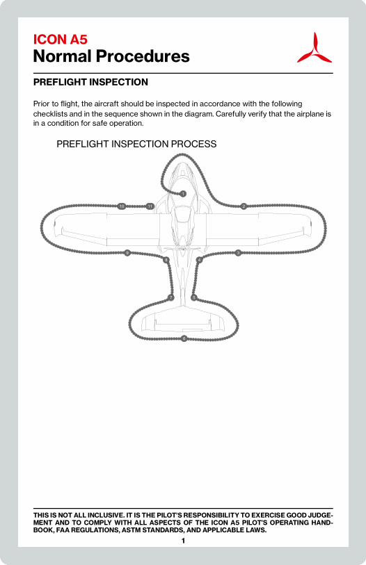
Normal ProceduresPREFLIGHT INSPECTION
Prior to flight, the aircraft should be inspected in accordance with the following checklists and in the sequence shown in the diagram. Carefully verify that the airplane is in a condition for safe operation.
PREFLIGHT INSPECTION PROCESS
10 2
9
8
7
6
5
4
3
1
11

ICON A5 Normal Procedures
2
THIS IS NOT ALL INCLUSIVE. IT IS THE PILOT’S RESPONSIBILITY TO EXERCISE GOOD JUDGE-MENT AND TO COMPLY WITH ALL ASPECTS OF THE ICON A5 PILOT’S OPERATING HAND-BOOK, FAA REGULATIONS, ASTM STANDARDS, AND APPLICABLE LAWS.
(1) Cabin
1. Baggage Area—SECURE stored items
2. Throttle Lever—CHECK freedom of motion
3. Controls—CHECK freedom of motion to all stops
4. Landing Gear Switch—VISUALLY CHECK DOWN (land)/UP (water)
5. Rudder Pedal Area and Parking Brake—CHECK clear and no fluid leaks
6. Master Switch—ON
7. Strobe Lights—VERIFY all lights illuminate
8. Fuel Quantity—CHECK/CONFIRM
9. Landing Gear Position Indicator—VISUALLY VERIFY DOWN (land)/UP (water)
10. Bilge Pump—ON (verify operation & bilge empty)/OFF
11. Water Rudder—VISUALLY inspect and VERIFY operation
12. Circuit Breakers and Fuses—CHECK IN and NONE LIT
13. Master Switch—OFF
14. Canopy Frame, Seal, and Latch—CHECK CONDITION
15. Canopy/Windows—CHECK general condition
16. Fuselage Left Nose—CHECK CONDITION
17. Fresh Air Vent Scoop—CLEAR
18. Nose Gear Strut and Mechanism—CHECK CONDITION
19. Aft Nose Gear Doors—CHECK CONDITION and CONFIRM locked in down position
20. Fuselage Right Nose—CHECK CONDITION
(2) Right Wing LE and Tip
1. Seawings™ LE—CHECK CONDITION and SECURE
2. Wing Lock Handle—CHECK LOCKED and SECURE
3. Wing Inspection Panels (2)—CHECK SECURE
4. Wing Stall Strip—CHECK SECURE
5. Wing Tie Down Fitting—REMOVE
6. Wing LE and HT Hanger Fitting—CHECK CONDITION
7. Wing Vortex Generators (17 Pair)—CHECK SECURE
8. Wing Tip and Lights—CHECK CONDITION
ICON A5
3
Normal Procedures
THIS IS NOT ALL INCLUSIVE. IT IS THE PILOT’S RESPONSIBILITY TO EXERCISE GOOD JUDGE-MENT AND TO COMPLY WITH ALL ASPECTS OF THE ICON A5 PILOT’S OPERATING HAND-BOOK, FAA REGULATIONS, ASTM STANDARDS, AND APPLICABLE LAWS.
(3) Right Wing TE
1. Aileron and Hinges—CHECK FREE and SECURE
2. Top of Wing—CHECK for DAMAGE
3. Flap, Hinges, and Root Fence—CHECK CONDITION
(4) Right Inboard Wing and Engine
1. Parachute Cover—CHECK SECURE
2. Main Landing Gear—CHECK CONDITION
3. Tires—CHECK CONDITION, wear
4. Brakes—CHECK CONDITION, wear, fluid leaks
5. Seawings™ and Hull Step—NO DAMAGE
6. Fuselage Vortex Generators (5)—CHECK SECURE
7. Aft Cowl and Exhaust—SECURE, NO CRACKS
8. Coolant Overflow Bottle—VERIFY LEVEL between min and max
9. Propeller and Spinner—SECURE, NO NICKS
10. Cooling Outlet and Fan—CLEAR, GOOD CONDITION
(5) Right Tail Boom
1. Firewall Drain—CHECK CLEAR
2. Top of Tail Boom Under Propeller—CLEAR OF WATER/DEBRIS
3. Tail Boom and Hull—CHECK CONDITION and CLEAR OF DEBRIS
4. Water Rudder and Access Panel—SECURE, NO DAMAGE
5. Tail Cone Access Panel—SECURE
6. Tail Tie Down—CHECK CONDITION and UNTIE
(6) Tail Surfaces
1. Vertical Tail and HT/VT Joint—CHECK CONDITION and SECURITY
2. Right HT and Tip—VERIFY CONDITON and LOCKED
3. Rudder—CHECK FREE and in GOOD CONDITION

ICON A5 Normal Procedures
4
THIS IS NOT ALL INCLUSIVE. IT IS THE PILOT’S RESPONSIBILITY TO EXERCISE GOOD JUDGE-MENT AND TO COMPLY WITH ALL ASPECTS OF THE ICON A5 PILOT’S OPERATING HAND-BOOK, FAA REGULATIONS, ASTM STANDARDS, AND APPLICABLE LAWS.
NOTE: The rudder is spring-centered with a minor offset to the right. This is normal and should not be adjusted.
4. Static Ports (2)—CHECK CLEAN with CRESCENTS IN PLACE
5. Elevator, Hinges, and Pushrod—CHECK FREE and SECURE
6. Trim Tab and Pushrod—CHECK CONDITION and WITHOUT EXCESSIVE PLAY
7. Left HT and Tip—VERIFY CONDITON and LOCKED
(7) Left Tail Boom
1. Tail Boom and Hull—CHECK CONDITION
(8) Left Inboard Wing
1. Aft Cowl and Exhaust—SECURE, NO CRACKS
2. Seawings™ and Hull Step—NO DAMAGE
3. Fuselage Vortex Generators (5)—CHECK SECURE
4. Main Landing Gear—CHECK CONDITION
5. Tires—CHECK CONDITION, wear
6. Brakes—CHECK CONDITION, wear, fluid leaks
(9) Left Wing TE
1. Flap, Hinges, and Root Fence—CHECK CONDITION
2. Top of Wing—CHECK for DAMAGE
3. Aileron and Hinges—CHECK FREE and SECURE
ICON A5
5
Normal Procedures
THIS IS NOT ALL INCLUSIVE. IT IS THE PILOT’S RESPONSIBILITY TO EXERCISE GOOD JUDGE-MENT AND TO COMPLY WITH ALL ASPECTS OF THE ICON A5 PILOT’S OPERATING HAND-BOOK, FAA REGULATIONS, ASTM STANDARDS, AND APPLICABLE LAWS.
(10) Left Wing Tip and LE
1. Wing Tip and Lights—CHECK CONDITION
2. Wing Vortex Generators (17 pair)—CHECK SECURE
3. Wing LE and HT Hanger Fitting—CHECK CONDITION
4. AOA Ports (2)—CHECK CLEAR
5. Wing Tie Down Fitting—REMOVE
6. Wing Stall Strip—CHECK SECURE
7. Wing Inspection Panels (2)—CHECK SECURE
8. Fuel Vent—CHECK CLEAR
9. Wing Lock Handle—CHECK LOCKED and SECURE
10. Pitot Tube—CHECK CLEAR
11. Seawings™ LE—CHECK CONDITION
12. Bilge Outlet—CHECK CLEAR
(11) Fuel and Engine Oil
1. Fuel Cap—REMOVE
2. Fuel—SUMP via access port and INSPECT fuel
3. Fuel Cap—SECURE (tab swings down)
4. Ignition Switch—OFF and key REMOVED
5. Oil Filler Cap—REMOVE via access door
6. Propeller—TURN SLOWLY CCW (behind prop facing forward) several times by hand, holding pressure for several seconds against each compression stroke, until oil ‘burps’
7. Oil Level—CHECK, SERVICE as necessary, then secure cap and door
8. Cowling—CHECK condition/VERIFY secure
9. Engine Inlet—CLEAR

ICON A5 Normal Procedures
6
THIS IS NOT ALL INCLUSIVE. IT IS THE PILOT’S RESPONSIBILITY TO EXERCISE GOOD JUDGE-MENT AND TO COMPLY WITH ALL ASPECTS OF THE ICON A5 PILOT’S OPERATING HAND-BOOK, FAA REGULATIONS, ASTM STANDARDS, AND APPLICABLE LAWS.
BEFORE COCKPIT ENTRY
1. Chocks and Tie Downs—VERIFY REMOVED
2. Aircraft Documents—VERIFY/REVIEW
3. Preflight Planning—COMPLETE
4. Takeoff Data—CALCULATE as required
5. Life Vest(s)—GOOD CONDITION/DON (as required)
6. Windows—BOTH IN or BOTH REMOVED
7. Wind Deflectors—BOTH INSTALLED (if windows removed)
AFTER COCKPIT ENTRY
1. Canopy—LOWERED to detent or CLOSED
2. Belts/Harnesses—FASTEN
3. Headsets—CONNECTED
4. Landing Gear Switch—DOWN (land)/UP (water)
5. Electrical Switches—ALL OFF (or as required)
6. Master Switch—ON
7. Annunciator Panel—PRESS to test; VERIFY all lights illuminate
8. Landing Gear Position Indicator—DOWN (land)/UP (water)
9. Bilge Pump—On (verify operation & bilge empty)/OFF
10. Fuel Valve—ON
11. IPS Safety Pin—REMOVE and stow
ENGINE START
1. Strobes—ON
2. Brakes—TEST and SET
3. Throttle—OPEN 1/2”
4. Area Around Aircraft—CLEAR
5. Ignition Switch
a. A—pause 6 sec confirm FUEL PRESS light OUT
b. B—pause 6 sec confirm FUEL PRESS light OUT
c. BOTH—confirm ENGINE + LAND AIRCRAFT lights OUT
d. START—RELEASE as engine fires

ICON A5
7
Normal Procedures
THIS IS NOT ALL INCLUSIVE. IT IS THE PILOT’S RESPONSIBILITY TO EXERCISE GOOD JUDGE-MENT AND TO COMPLY WITH ALL ASPECTS OF THE ICON A5 PILOT’S OPERATING HAND-BOOK, FAA REGULATIONS, ASTM STANDARDS, AND APPLICABLE LAWS.
NOTE: Max crank time is 10 seconds, followed by 2 minutes off.
5. Throttle—ADJUST to 2000 RPM
6. Oil Pressure—MONITOR; shutdown if not up in 10 seconds
7. Throttle—ADVANCE above 2500 RPM until ALTERNATOR light out
BEFORE TAXI
1. Radio—SET as required
2. Transponder—VERIFY VFR (1200)
3. AWOS — RECORD as required
4. Altimeter—SET/VERIFY
5. GPS—SET as required
6. Exterior Lights—ON as required
7. Engine Instruments—CHECK
TAXIING
CAUTION: Extended periods of idle taxiing can cause engine coolant temperature to exceed limits. Best cooling on the ground is achieved with engine set 3000-4000 rpm.
Land
1. Parking Brake—RELEASE
2. Brakes—CHECK
3. Steering—CHECK
Water
1. Landing Gear—UP, or as required
2. Flaps—UP (0°)
3. Water Rudder—DOWN, or as required for improved authority
ICON A5 Normal Procedures
8
THIS IS NOT ALL INCLUSIVE. IT IS THE PILOT’S RESPONSIBILITY TO EXERCISE GOOD JUDGE-MENT AND TO COMPLY WITH ALL ASPECTS OF THE ICON A5 PILOT’S OPERATING HAND-BOOK, FAA REGULATIONS, ASTM STANDARDS, AND APPLICABLE LAWS.
ENGINE RUN-UP
1. Throttle—ADVANCE TO 4000 RPM
2. Ignition Switch—B (pause until LAND AIRCRAFT AND ENGINE lights illuminate)
3. Ignition Switch—A (pause 6 seconds)
a. RPM: 180 max drop from original
b. FUEL PRESSURE Annunciator—OUT
3. Ignition Switch—B (pause 6 seconds)
a. RPM—180 max drop from original
b. FUEL PRESSURE Annunciator—OUT
3. Ignition Switch—BOTH
4. Annunciator Panel—ALL LIGHTS OUT
5. Engine Instruments—CHECK
6. Throttle—RETARD to idle
NOTE: During the ignition check, the RPM may increase when oper-ating on a single lane. This is normal; the original RPM will be restored after a short time operating on both lanes.
AUTOPILOT PRE-FLIGHT (IF APPLICABLE)
1. Autopilot—ENGAGE using AP/CWS button, or AP button on mode controller
2. Flight Controls—VERIFY autopilot can be overpowered in both pitch and roll
3. AP DISC Button—PRESS and VERIFY autopilot disengages and audio alert is heard
4. Flight Director—SET FOR TAKEOFF (VS mode or push FD Button to turn off the Flight Director)
5. Flight Controls—VERIFY autopilot servos are disengaged from pitch and roll and all controls move freely
BEFORE TAKEOFF
1. Flight Controls—FREE and CORRECT
2. Flaps—CHECK operation
3. Trim—SET for takeoff
4. Instruments—CHECK
5. Canopy—LATCHED

ICON A5
9
Normal Procedures
THIS IS NOT ALL INCLUSIVE. IT IS THE PILOT’S RESPONSIBILITY TO EXERCISE GOOD JUDGE-MENT AND TO COMPLY WITH ALL ASPECTS OF THE ICON A5 PILOT’S OPERATING HAND-BOOK, FAA REGULATIONS, ASTM STANDARDS, AND APPLICABLE LAWS.
RUNWAY TAKEOFF
Normal Takeoff
1. Flaps—UP (0°)
2. Throttle—MAX
3. Engine Instruments—CHECK
4. Stick—Rotate at 50 KIAS
5. Landing Gear—RETRACT at positive rate of climb (<75 KIAS)
Short Field Takeoff
1. Flaps—HALF (15°)
2. Brakes—HOLD
3. Throttle—smoothly advance to MAX
4. Engine Instruments—CHECK
5. Brakes—RELEASE
6. Stick—ROTATE at 45 KIAS
7. Landing Gear—RETRACT at positive rate of climb (<75 KIAS)
8. Climb at VX (50 KIAS) until obstacles cleared (if required)
9. Flaps—RETRACT once cleared of obstacles or climbing through 100ft AGL
Soft Field Takeoff
1. Flaps—HALF (15°)
2. Stick—FULL AFT
3. Throttle—smoothly advance to MAX
4. Engine Instruments—CHECK
5. At Nosewheel Liftoff—Relax stick pressure to stay inside ground effect until suffi-cient energy is gained
6. Landing Gear—RETRACT at positive rate of climb (<75 KIAS)
7. Climb at VX (50 KIAS) until obstacles cleared (if required)
8. Flaps—RETRACT once cleared of obstacles or climbing through 100ft AGL

ICON A5 Normal Procedures
10
THIS IS NOT ALL INCLUSIVE. IT IS THE PILOT’S RESPONSIBILITY TO EXERCISE GOOD JUDGE-MENT AND TO COMPLY WITH ALL ASPECTS OF THE ICON A5 PILOT’S OPERATING HAND-BOOK, FAA REGULATIONS, ASTM STANDARDS, AND APPLICABLE LAWS.
WATER TAKEOFF
Step Taxi/Takeoff
1. Bilge Pump—ON (verify bilge empty) / OFF
2. Landing Gear—UP, indicating up
3. Flaps—FULL (30°)
4. Water Rudder—UP
5. Throttle—MAX
6. Stick—POSITION for minimum water drag
7. Flaps—RETRACT when safely airborne above 50 KIAS (<75 KIAS)
WARNING: Contacting the wing tip with the water while in motion can create a dangerous situation and must be avoided.
CAUTION: Prolonged step taxi should only be conducted in glassy or normal water conditions.
CAUTION: Rough water takeoffs are considered an advanced tech-nique and should not be performed by beginning or rela-tively inexperienced seaplane pilots.
CAUTION: Takeoff distance will be extended with less than full flaps set.
NOTE: Ideal step taxi speed is 20-25kts GS.
CLIMB
1. AOA—WHITE LINE
2. Instruments—MONITOR
3. Landing Gear—VERIFY UP
CRUISE
1. Cruise Power—SET
2. Fuel Quantity—MONITOR
3. Instruments—MONITOR

ICON A5
11
Normal Procedures
THIS IS NOT ALL INCLUSIVE. IT IS THE PILOT’S RESPONSIBILITY TO EXERCISE GOOD JUDGE-MENT AND TO COMPLY WITH ALL ASPECTS OF THE ICON A5 PILOT’S OPERATING HAND-BOOK, FAA REGULATIONS, ASTM STANDARDS, AND APPLICABLE LAWS.
DESCENT
1. Throttle—AS REQUIRED
2. Landing Gear—AS REQUIRED
RUNWAY LANDING
Approach
1. Landing Gear—EXTEND for the runway (<75 KIAS), indicating down
2. Flaps—UP (0°), or as desired for type of landing
3. Water Rudder—UP
4. Brakes—CHECK for firmness and parking brake OFF
5. AOA—WHITE LINE
NOTE: Recommended power setting for approach and touchdown is 3000 rpm
Normal Landing
1. AOA—YELLOW LINE, at touchdown
2. Throttle—IDLE, after touchdown
3. Braking—MINIMUM REQUIRED
Short Field Landing
1. Flaps—FULL (30°, <75 KIAS) before short final
2. AOA—YELLOW LINE, Short final
3. AOA—MID YELLOW, at touchdown
4. Throttle—IDLE, after touchdown
5. Braking—AS NEEDED

ICON A5 Normal Procedures
12
THIS IS NOT ALL INCLUSIVE. IT IS THE PILOT’S RESPONSIBILITY TO EXERCISE GOOD JUDGE-MENT AND TO COMPLY WITH ALL ASPECTS OF THE ICON A5 PILOT’S OPERATING HAND-BOOK, FAA REGULATIONS, ASTM STANDARDS, AND APPLICABLE LAWS.
Soft Field Landing
1. Flaps—FULL (30°, <75 KIAS) before short final
2. AOA—YELLOW LINE, Short final
3. AOA—MID YELLOW, at touchdown
4. Throttle—AS REQUIRED
5. Stick—Apply back stick to hold nose off ground
6. Braking—MINIMIZE and maintain AFT stick during roll out
WATER LANDING
Approach
1. Landing Gear—UP for water, indicating up
2. Flaps—FULL (30°, <75 KIAS)
3. Water Rudder—UP
4. AOA—WHITE LINE
WARNING: Confirm landing gear up for water landing. Aircraft may flip inverted if landed on water with landing gear extended.
Normal Water Landing
1. AOA—YELLOW LINE, at touchdown
2. Throttle—IDLE, smoothly reduce power once touched down
3. Stick—AFT, increase back pressure as you settle into the water
NOTE: Recommended power setting for approach and touchdown is 3000 rpm.
Rough Water Landing
1. AOA—MID YELLOW, at touchdown
2. Throttle—Increase RPM slightly (~100-200rpm) before touchdown
3. Stick—AFT, increase back pressure as you settle into the water
CAUTION: Touching down on the front or back side of a swell can induce porpoising. Control any porpoise by resetting the stick slightly AFT and maintain or increase power as needed

ICON A5
13
Normal Procedures
THIS IS NOT ALL INCLUSIVE. IT IS THE PILOT’S RESPONSIBILITY TO EXERCISE GOOD JUDGE-MENT AND TO COMPLY WITH ALL ASPECTS OF THE ICON A5 PILOT’S OPERATING HAND-BOOK, FAA REGULATIONS, ASTM STANDARDS, AND APPLICABLE LAWS.
to dampen oscillations and settle into the water. Do not abruptly reduce power while in a porpoise.
Glassy Water Landing
1. Locate suitable shoreline visual reference
2. GPS—Select HSI/panel display for VSI reference (if on-board and desired)
3. Final Approach Path—as close to visual reference as practical
No later than last visual reference:
4. AOA—YELLOW LINE
5. Throttle—Set RPM to establish 100-150 ft/min decent (approx 3700-4000 RPM)
6. After Touchdown—Smoothly reduce power to idle
7. Stick—AFT, increase back pressure as you settle into the water
BALKED LANDING
1. Throttle—MAX
2. AOA—white line
3. Flaps—RETRACT after positive rate of climb
BEFORE RAMPING
Water to Ramp
1. Throttle—IDLE
2. Flaps—UP
3. Landing Gear—EXTEND (<4kts GS)
CAUTION: Ramping with landing gear not fully down will damage the landing gear.
4. Water Rudder—UP, before entering the ramp

ICON A5 Normal Procedures
14
THIS IS NOT ALL INCLUSIVE. IT IS THE PILOT’S RESPONSIBILITY TO EXERCISE GOOD JUDGE-MENT AND TO COMPLY WITH ALL ASPECTS OF THE ICON A5 PILOT’S OPERATING HAND-BOOK, FAA REGULATIONS, ASTM STANDARDS, AND APPLICABLE LAWS.
Ramp to Water
1. Throttle—IDLE
2. Flaps—UP
3. Landing Gear—DOWN, make certain nose wheel is centered before entering water
4. Water Rudder—UP
5. Brakes—RELEASE, use brakes to control entry into water
After Entry
6. Landing Gear—RETRACT once fully buoyant (<4kts GS)
BEFORE BEACHING
1. Throttle—IDLE
2. Canopy—UNLATCH
3. Seatbelt—OFF
4. Headsets—OFF
5. Water Rudder—UP, before hitting shallow waters
6. Ignition—OFF, prior to touching the shoreline
7. Proceed to “Shutdown” on page 14
NOTE: It is recommended to beach the A5 bow-on to any suitable beach area. The beach should be smooth sand and free of debris to avoid damage to the hull.
SHUTDOWN
1. Brakes—HOLD (on land)
2. Flaps—UP
3. Trim—SET takeoff
4. Engine—STABILIZE at idle (2 minutes in hot conditions)
5. Ignition Switch—OFF
6. Radio and Transponder—OFF (if applicable)
7. Lights— ALL OFF
8. Master Switch—OFF
9. Parking Brake—SET (if desired)
10. IPS Safety Pin—INSTALL

ICON A5
15
Normal Procedures
THIS IS NOT ALL INCLUSIVE. IT IS THE PILOT’S RESPONSIBILITY TO EXERCISE GOOD JUDGE-MENT AND TO COMPLY WITH ALL ASPECTS OF THE ICON A5 PILOT’S OPERATING HAND-BOOK, FAA REGULATIONS, ASTM STANDARDS, AND APPLICABLE LAWS.
POST-FLIGHT INSPECTION
1. Propeller—CHECK for nicks, water damage
2. Bilge Pump—RUN until no water; then confirm bilge pump and master switch OFF
3. Tie Downs and Chocks—AS REQUIRED
4. General Aircraft Condition—INSPECT

ICON A5 Normal Procedures
16
THIS IS NOT ALL INCLUSIVE. IT IS THE PILOT’S RESPONSIBILITY TO EXERCISE GOOD JUDGE-MENT AND TO COMPLY WITH ALL ASPECTS OF THE ICON A5 PILOT’S OPERATING HAND-BOOK, FAA REGULATIONS, ASTM STANDARDS, AND APPLICABLE LAWS.

ICON A5
17
THIS IS NOT ALL INCLUSIVE. IT IS THE PILOT’S RESPONSIBILITY TO EXERCISE GOOD JUDGE-MENT AND TO COMPLY WITH ALL ASPECTS OF THE ICON A5 PILOT’S OPERATING HAND-BOOK, FAA REGULATIONS, ASTM STANDARDS, AND APPLICABLE LAWS.
Emergency ProceduresGENERAL INFORMATION
This section provides checklists and procedures for coping with emergencies that may occur. Emergencies caused by airplane malfunctions are rare if proper preflight inspections and maintenance are practiced. En-route weather emergencies may be minimized by careful flight planning and good judgment when unexpected weather is encountered. Should an emergency arise, the basic guidelines in this section should be considered and applied as necessary to correct the problem.
The A5 has a series of annunciator lights that assist the pilot in assessing the criticality of various situations.
The following terminology is used to categorize the level of urgency to land the aircraft during an abnormal or emergency situation:
Land as soon as practical
Extended flight is not recommended. The landing site and duration of flight is at the discretion of the pilot. Flying to a nearby airport with support services is recommended.
Land as soon as possible
Fly toward the nearest suitable landing area (runway or water) while being prepared to execute the “Engine Failure In-Flight” on page 23 to an emergency landing site (e.g. road).
Precautionary Landing
A premeditated landing, on or off an airport, when further flight is possible but inadvisable. Examples of conditions that may call for a precautionary landing include deteriorating weather, being lost, fuel shortage, and gradually developing engine trouble.
Forced Landing
An immediate landing, on or off an airport, necessitated by the inability to continue further flight. A typical example of which is an airplane forced down by engine failure.
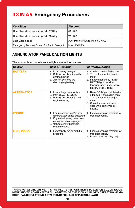
AIRSPEEDS FOR EMERGENCY OPERATIONS
Condition Airspeed
Engine Failure After Takeoff AOA-Pitch for white line (~60 KIAS)
Engine Failure In-Flight AOA-Pitch for white line (~60 KIAS)
Precautionary Landing with Engine Power AOA-Pitch for white line (~60 KIAS)
ICON A5 Emergency Procedures
THIS IS NOT ALL INCLUSIVE. IT IS THE PILOT’S RESPONSIBILITY TO EXERCISE GOOD JUDGE-MENT AND TO COMPLY WITH ALL ASPECTS OF THE ICON A5 PILOT’S OPERATING HAND-BOOK, FAA REGULATIONS, ASTM STANDARDS, AND APPLICABLE LAWS.
18
ANNUNCIATOR PANEL CAUTION LIGHTS
The annunciator panel caution lights are amber in color.
Operating Maneuvering Speed—1510 lbf 87 KIAS
Operating Maneuvering Speed—1145 lbf 76 KIAS
Best Glide Speed AOA-Pitch for white line (~60 KIAS)
Emergency Descent Speed for Rapid Descent Max 120 KIAS
Caution Cause/Remarks Corrective Action
BATTERY 1. Low battery voltage.2. Battery not charging with
engine running.3. Aircraft systems are
discharging battery.
1. Confirm Master Switch ON.2. Turn off non-critical equip-
ment.3. If accompanied by ALTER-
NATOR light, consider lowering landing gear while battery is still strong.
ALTERNATOR 1. Low voltage on main bus.2. If flying, ALT B failure.3. Battery not charging with
engine running.
1. Reset 30 Amp circuit breaker if tripped. If trips again then:
2. Turn off non-critical equip-ment.
3. Consider lowering landing gear while battery is still strong.
ENGINE 1. Engine component/sensor failure/exceedance detected.
2. Engine limits may have been exceeded; check gauges.
3. 10 hours max flight time recommended.
1. Land as soon as practical for troubleshooting.
FUEL PRESS 1. Excessively low or high fuel pressure.
1. Land as soon as practical for troubleshooting.
2. Power reduction may help.
Condition Airspeed

ICON A5 Emergency Procedures
19
THIS IS NOT ALL INCLUSIVE. IT IS THE PILOT’S RESPONSIBILITY TO EXERCISE GOOD JUDGE-MENT AND TO COMPLY WITH ALL ASPECTS OF THE ICON A5 PILOT’S OPERATING HAND-BOOK, FAA REGULATIONS, ASTM STANDARDS, AND APPLICABLE LAWS.
ANNUNCIATOR PANEL WARNING LIGHTS
The annunciator panel warning lights are red in color.
ICON PARACHUTE SYSTEM (IPS) ACTUATION
IPS actuation is recommended for any of the following:
• Loss of Aircraft Control
• Engine Failure with NO SUITABLE landing area
Warning Cause/Remarks Corrective Action
PURGE BILGE 1. At least 1 gallon of water in bilge.
2. Could create weight or CG out of limits.
1. Bilge pump—ON.If light remains on:
1. Do not takeoff.
SECURE WING/TAIL 1. One or more sensors indicate unlocked.
2. Does not identify affected sensor.
On ground:
1. Do not takeoff.2. Confirm wings/tails locked.In flight:
1. Minimize maneuvering.2. Land as soon as practical.
LAND AIRCRAFT+ FUEL PRESS
1. Critically low or high fuel pres-sure.
1. Land as soon as possible.
LAND AIRCRAFT+ ENGINE
1. Critical engine component or sensor failure.
2. Engine limits may have been exceed.
1. Land as soon as possible.2. Check Gauges.
LAND AIRCRAFT+ ENGINE+ ALTERNATOR
1. Low voltage on main bus.2. If flying, ALT A failure.
1. Turn off non-critical equip-ment.
2. Land as soon as possible.3. Consider lowering landing
gear while battery still strong.
LAND AIRCRAFT+ ALTERNATOR+ BATTERY
1. Excessively low battery.2. If flying, Alt B failure.3. Battery not charging with
engine running.4. ALT A may also have failed.
1. Confirm Master Switch ON.2. Turn off non-critical equip-
ment.3. Land as soon as possible.4. Lower landing gear now if
land landing.NOTE: Battery life may limit engine run time.
LAND AIRCRAFT+ ENGINE+ ALTERNATOR+ BATTERY
1. Excessively low battery.2. If flying, Alt A failure.3. Battery not charging with
engine running.4. ALT B may also have failed.
1. Confirm Master Switch ON.2. Turn off non-critical equip-
ment.3. Land as soon as possible.4. Lower landing gear now if
land landing.NOTE: Battery life may limit engine run time.

ICON A5 Emergency Procedures
THIS IS NOT ALL INCLUSIVE. IT IS THE PILOT’S RESPONSIBILITY TO EXERCISE GOOD JUDGE-MENT AND TO COMPLY WITH ALL ASPECTS OF THE ICON A5 PILOT’S OPERATING HAND-BOOK, FAA REGULATIONS, ASTM STANDARDS, AND APPLICABLE LAWS.
20
• Pilot Incapacitation or inability to cope with situation or flight conditions
Parachute Deployment
1. Safety Pin—CONFIRM REMOVED, Remove if necessary
2. Parachute Handle—PULL HARD
3. Ignition Key—OFF
4. Master Switch—OFF (right before touchdown)
Notes:Approximately 48 lbf of force is required to actuate the IPS.
Optimal IPS actuation is from level flight above 500 ft AGL.
Descent rate under parachute will be approximately 1200 ft/min.
Landing gear will automatically extend following IPS actuation. Once extended, it cannot be raised.
Seat belts should remain secure during descent until contact with the surface and all motion stops.
At pilot’s discretion, consider unlocking canopy and removing windows during descent.
Exit the aircraft after all motion stops.
The ELT may not activate during IPS deployment or touchdown. It is therefore recommended to manually activate the ELT during the descent.
INADVERTENT SPIN/LOSS OF CONTROL
1. IPS Handle—PULL HARD
2. Ignition Key—OFF
3. Proceed to “Parachute Deployment” on page 20
WARNING: The aircraft has not been certified for traditional spin recovery and the only approved method of spin recovery is activation of the IPS.
AUTOPILOT LOSS OF CONTROL
If autopilot begins to behave unexpectedly, run away from a steady condition, or approach an unusual attitude:

ICON A5 Emergency Procedures
21
THIS IS NOT ALL INCLUSIVE. IT IS THE PILOT’S RESPONSIBILITY TO EXERCISE GOOD JUDGE-MENT AND TO COMPLY WITH ALL ASPECTS OF THE ICON A5 PILOT’S OPERATING HAND-BOOK, FAA REGULATIONS, ASTM STANDARDS, AND APPLICABLE LAWS.
1. Red Autopilot Disengage Button—PRESS
2. Recover manually to straight and level flight
3. If autopilot fails to disengage, proceed to “Failed Autopilot Disengagement” on page 21
FAILED AUTOPILOT DISENGAGEMENT
1. Overpower the autopilot servos to reach straight and level flight. The forces on the stick will be higher than normal but can be overpowered and flown by hand.
2. Once control of the aircraft is established, if forces persist, PULL the autopilot fuse from the overhead panel.
INADVERTENT IMC (AUTOPILOT INSTALLED)
Perform the following steps on the Autopilot Control Panel.
1. Blue LVL Button—PRESS
2. TRK Button—PRESS. The selected track bug should align with your current track on the PFD.
3. HDG/TRK Knob—TURN so that the selected track bug is 180° from current track
4. Wait for the aircraft to exit IMC conditions back in the direction you came from.
INADVERTENT ICING ENCOUNTER (NO AUTOPILOT INSTALLED)
1. Exit Icing Conditions.
CAUTION: The presence of even small amounts of ice on the airframe may increase stall speed, decrease stall angle of attack and reduce performance including climb rate.
ENGINE FIRE ON GROUND/START
1. Ignition—OFF
2. Master Switch—OFF
3. Egress Airplane

ICON A5 Emergency Procedures
THIS IS NOT ALL INCLUSIVE. IT IS THE PILOT’S RESPONSIBILITY TO EXERCISE GOOD JUDGE-MENT AND TO COMPLY WITH ALL ASPECTS OF THE ICON A5 PILOT’S OPERATING HAND-BOOK, FAA REGULATIONS, ASTM STANDARDS, AND APPLICABLE LAWS.
22
ENGINE FIRE IN FLIGHT
1. Ignition—OFF
2. Master Switch—OFF
3. Fuel Valve—OFF
4. Proceed to “Emergency Rapid Descent” on page 22 or “Forced Landing” on page 25 as required.
ELECTRICAL FIRE IN FLIGHT
1. Master Switch—OFF
2. Alternator Circuit Breaker—PULL (in overhead console)
NOTE: The above actions will not affect engine operation.3. Land As Soon As Possible
EMERGENCY RAPID DESCENT
1. Throttle—IDLE
2. Flaps—UP
3. Airspeed—
ABNORMAL ENGINE VIBRATION
1. Throttle—Reduce to minimum practical
2. Assess Vibration—Take action
Option Actions
Smooth Air 120 KIAS
Rough Air 90 KIAS
MY17 Aircraft, Windows Removed 90 KIAS
Option Actions
If vibration stops. 1. Land as soon as practical
If vibration continues. 1. Land as soon as possible (suitable landing area)

ICON A5 Emergency Procedures
23
THIS IS NOT ALL INCLUSIVE. IT IS THE PILOT’S RESPONSIBILITY TO EXERCISE GOOD JUDGE-MENT AND TO COMPLY WITH ALL ASPECTS OF THE ICON A5 PILOT’S OPERATING HAND-BOOK, FAA REGULATIONS, ASTM STANDARDS, AND APPLICABLE LAWS.
ENGINE FAILURE DURING TAKEOFF PRIOR TO LIFTOFF
1. Throttle—IDLE
2. Brakes—AS REQUIRED
ENGINE FAILURE AFTER TAKEOFF
1. AOA—White line
2. Landing Site—SELECT
3. Landing Gear—As Required
If time permits
4. Flaps—As Required
5. Ignition Key—OFF
6. Master Switch—OFF
7. Fuel Valve—OFF
NOTE: In most situations, when the engine fails below 300ft AGL, the landing should be made straight ahead, turning only to avoid obstructions.
ENGINE FAILURE IN-FLIGHT
1. AOA—white line
2. Landing Site—SELECT
3. Confirm:
a. Throttle—above idle
b. Master Switch—ON
c. Ignition—BOTH
d. Fuel Valve—ON
5. If engine does not restart, proceed to “Forced Landing” on page 25 or “Parachute Deployment” on page 20 as required.
NOTE: Recommended landing configuration for off airport landing other than hard surface is GEAR UP.

ICON A5 Emergency Procedures
THIS IS NOT ALL INCLUSIVE. IT IS THE PILOT’S RESPONSIBILITY TO EXERCISE GOOD JUDGE-MENT AND TO COMPLY WITH ALL ASPECTS OF THE ICON A5 PILOT’S OPERATING HAND-BOOK, FAA REGULATIONS, ASTM STANDARDS, AND APPLICABLE LAWS.
24
COOLANT TEMPERATURE HIGH
Ground
1. Throttle—ADVANCE to 3000-4000 RPM (if feasible)
If high coolant temperature persists:
2. Shutdown as soon as practical
NOTE: Use of cabin heater may help reduce coolant temperature.
In Flight
1. Throttle—REDUCE power to minimum required
2. Airspeed—INCREASE
If high coolant temperature persists:
3. Land as soon as possible
OIL PRESSURE-LOW/HIGH (IN THE RED)
Ground
1. Throttle—IDLE
2. Ignition—OFF as soon as practical
In Flight
1. Throttle—Reduce
2. Land as soon as possible

ICON A5 Emergency Procedures
25
THIS IS NOT ALL INCLUSIVE. IT IS THE PILOT’S RESPONSIBILITY TO EXERCISE GOOD JUDGE-MENT AND TO COMPLY WITH ALL ASPECTS OF THE ICON A5 PILOT’S OPERATING HAND-BOOK, FAA REGULATIONS, ASTM STANDARDS, AND APPLICABLE LAWS.
OIL TEMPERATURE HIGH
Ground
1. Throttle—ADVANCE to 3000-4000 RPM (if feasible)
If high oil temperature persists:
2. Shutdown as soon as possible
In Flight
1. Throttle—REDUCE
2. Airspeed—INCREASE
If high oil temperature persists:
3. Land as soon as possible
FORCED LANDING
1. AOA—White Line (~60 KIAS)
2. Landing Site—SELECT
3. Landing Gear and Flaps—As Required for type of landing
NOTE: Flaps will Reduce Glide distance. Flaps should not be selected until landing is assured.
4. Ignition Key—OFF
5. Canopy—Unlatch
If time permits
6. Transponder—Squawk 7700
7. Communicate intentions (121.5)
8. Fuel Valve—OFF
9. Master Switch—OFF
NOTE: AOA requires power. Once Master Switch is turned off, AOA indicator will not work.
NOTE: Recommended landing configuration for off airport landing other than hard surface is GEAR UP.
ICON A5 Emergency Procedures
THIS IS NOT ALL INCLUSIVE. IT IS THE PILOT’S RESPONSIBILITY TO EXERCISE GOOD JUDGE-MENT AND TO COMPLY WITH ALL ASPECTS OF THE ICON A5 PILOT’S OPERATING HAND-BOOK, FAA REGULATIONS, ASTM STANDARDS, AND APPLICABLE LAWS.
26
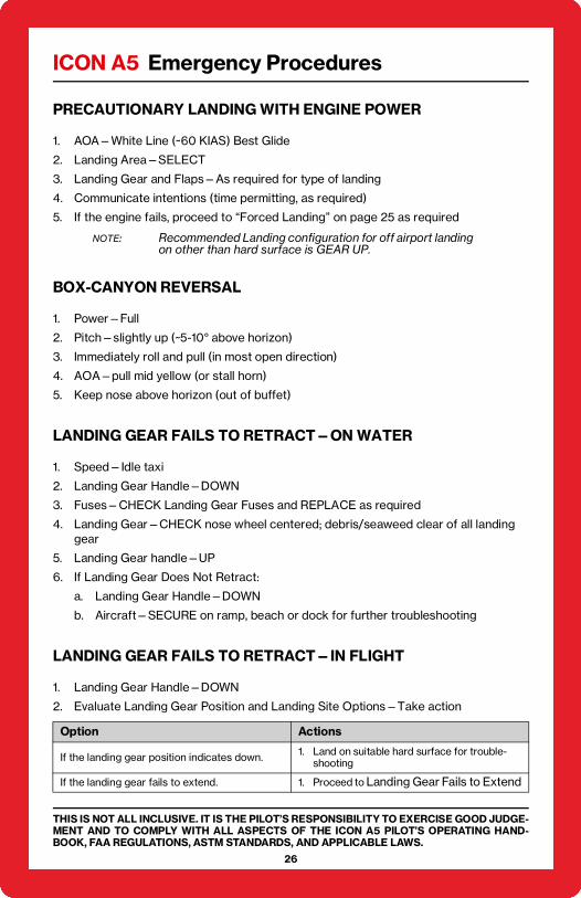
PRECAUTIONARY LANDING WITH ENGINE POWER
1. AOA—White Line (~60 KIAS) Best Glide
2. Landing Area—SELECT
3. Landing Gear and Flaps—As required for type of landing
4. Communicate intentions (time permitting, as required)
5. If the engine fails, proceed to “Forced Landing” on page 25 as required
NOTE: Recommended Landing configuration for off airport landing on other than hard surface is GEAR UP.
BOX-CANYON REVERSAL
1. Power—Full
2. Pitch—slightly up (~5-10° above horizon)
3. Immediately roll and pull (in most open direction)
4. AOA—pull mid yellow (or stall horn)
5. Keep nose above horizon (out of buffet)
LANDING GEAR FAILS TO RETRACT—ON WATER
1. Speed—Idle taxi
2. Landing Gear Handle—DOWN
3. Fuses—CHECK Landing Gear Fuses and REPLACE as required
4. Landing Gear—CHECK nose wheel centered; debris/seaweed clear of all landing gear
5. Landing Gear handle—UP
6. If Landing Gear Does Not Retract:
a. Landing Gear Handle—DOWN
b. Aircraft—SECURE on ramp, beach or dock for further troubleshooting
LANDING GEAR FAILS TO RETRACT—IN FLIGHT
1. Landing Gear Handle—DOWN
2. Evaluate Landing Gear Position and Landing Site Options—Take action
Option Actions
If the landing gear position indicates down. 1. Land on suitable hard surface for trouble-shooting
If the landing gear fails to extend. 1. Proceed to Landing Gear Fails to Extend
ICON A5 Emergency Procedures
27
THIS IS NOT ALL INCLUSIVE. IT IS THE PILOT’S RESPONSIBILITY TO EXERCISE GOOD JUDGE-MENT AND TO COMPLY WITH ALL ASPECTS OF THE ICON A5 PILOT’S OPERATING HAND-BOOK, FAA REGULATIONS, ASTM STANDARDS, AND APPLICABLE LAWS.
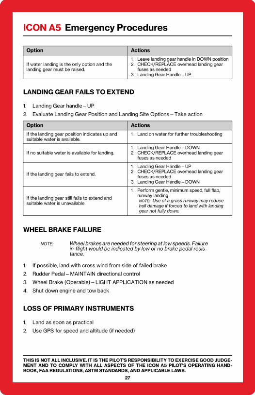
LANDING GEAR FAILS TO EXTEND
1. Landing Gear handle—UP
2. Evaluate Landing Gear Position and Landing Site Options—Take action
WHEEL BRAKE FAILURE
NOTE: Wheel brakes are needed for steering at low speeds. Failure in-flight would be indicated by low or no brake pedal resis-tance.
1. If possible, land with cross wind from side of failed brake
2. Rudder Pedal—MAINTAIN directional control
3. Wheel Brake (Operable)—LIGHT APPLICATION as needed
4. Shut down engine and tow back
LOSS OF PRIMARY INSTRUMENTS
1. Land as soon as practical
2. Use GPS for speed and altitude (if needed)
If water landing is the only option and the landing gear must be raised.
1. Leave landing gear handle in DOWN position2. CHECK/REPLACE overhead landing gear
fuses as needed3. Landing Gear Handle—UP
Option Actions
If the landing gear position indicates up and suitable water is available.
1. Land on water for further troubleshooting
If no suitable water is available for landing.1. Landing Gear Handle—DOWN2. CHECK/REPLACE overhead landing gear
fuses as needed
If the landing gear fails to extend.
1. Landing Gear Handle—UP2. CHECK/REPLACE overhead landing gear
fuses as needed3. Landing Gear Handle—DOWN
If the landing gear still fails to extend and suitable water is unavailable.
1. Perform gentle, minimum speed, full flap, runway landingNOTE: Use of a grass runway may reduce hull damage if forced to land with landing gear not fully down.
Option Actions

ICON A5 Emergency Procedures
THIS IS NOT ALL INCLUSIVE. IT IS THE PILOT’S RESPONSIBILITY TO EXERCISE GOOD JUDGE-MENT AND TO COMPLY WITH ALL ASPECTS OF THE ICON A5 PILOT’S OPERATING HAND-BOOK, FAA REGULATIONS, ASTM STANDARDS, AND APPLICABLE LAWS.
28
OVERVOLTAGE
1. Land as soon as possible
NOTE: The A5 has no overvoltage indicator, but smoke or an acid smell in the cockpit is an indication of overvoltage. (See “Electrical Fire in Flight” on page 22.)