chest radiology in icu
TRANSCRIPT

EMAN MAHMOUDLECTURER OF CHEST DISEASES
ASWAN UNIVERSITY

YOUR INTERPRETATION?

Chest radiographs on the same patient few minutes apart showing the effect of technique; the left image shows medistinal widening and basal cloudning due to poor inspiratory effort

PA vs AP
(posterioranterior) position. Note that the x-ray tube is 72 inches away.
the supine AP (anteriorposterior) position the x-ray tube is 40 inches
from the patient.


1-tubes2-lines
3-air in chest4-fluid in chest
5-vascular pedicles
AGENDA


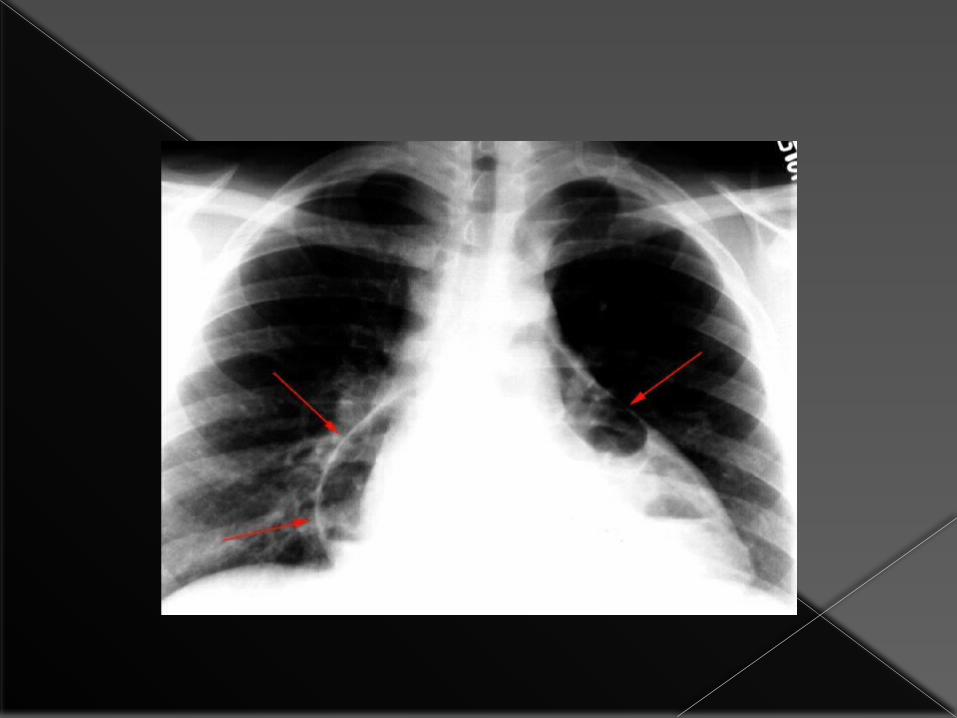
WHAT IS THE CAUSE OF THIS RADIOLOGICAL ABNORMALITY?
1.Pneumonia
2.Lung collapse due to mucous impaction
3.Malposition of endotracheal tube.
4.Fluid extravasation.
1.Pneumonia
2.Lung collapse due to mucous impaction
3.Malposition of endotracheal tube.
4.Fluid extravasation.
Why the CXR is useful in Tubes and Lines
To check it is in the right position To check for complications of
placement of the tube/line

What are the common tubes?
•Endotracheal tube
•Nasogastric tubes
•Intercostal chest drains
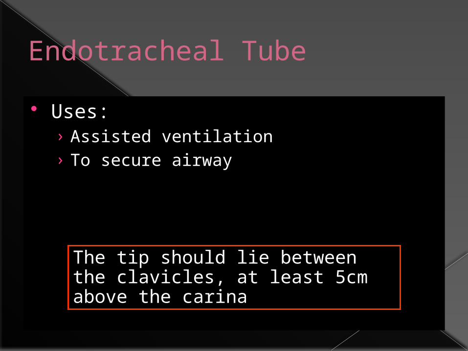
Endotracheal Tube Uses:
› Assisted ventilation› To secure airway
The tip should lie between the clavicles, at least 5cm above the carina

Correctly sited endotracheal tube
Dee method for approximating the position o f t he carina can be used.This involves defining the aortic arch and then drawing a lineInfer omedially through the middle of the arch at a45 degree angle to t he midline

The Ideal position for endotracheal tubes is in the mid trachea, 5cm from t he carina, when the head is neither flexed nor extended. This allows for movement of the tip with head movements. The minimal safe distance from the carina is 2cm.

What can go wrong with ET Tubes?
Tube too far advanced› Typically, within right main stem bronchus
Placement within oesophagus
Tracheal perforation
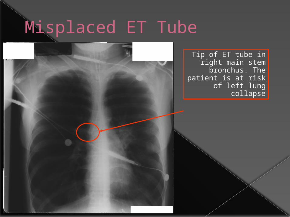
Misplaced ET TubeTip of ET tube in right main stem bronchus. The patient is at risk of left lung collapse


Nasogastric Tubes Uses:
› Decompression of dilated stomach› Administration of medication / nutritional
support
The tip should lie below the diaphragm with at least 10cm lying within the stomach

Optimum Position of NG tube
The tip should lie below the diaphragm coiled within the stomach

Satisfactory Position of NG tube
Tip of tube
Note that this patient also has small bilateral pleural
effusions

Frontal(A) and lateral (B) radiographs of the neck show An tube(arrow) coiled in the upper esophagus with its tip in the oropharynx(arrowhead)

•Generally a chest x-ray is not necessary following the placement of a nasogastric tube. •Feeding tubes are generally placed into the proximal small bowel, as confirmed by an abdominal film.•A chest x-ray may be obtained following the insertion of small-bore feeding tubes to rule out placement within the lung, which may have serious consequences

What can go wrong with NG Tubes?
Commonest (and most dangerous) is placement within bronchial tree› This can be FATAL if NG feeding occurs into
the lung Perforation of oesophagus is rare
Be suspicious of a misplaced NG tube if the patient is extremely uncomfortable during tube insertion with severe coughing
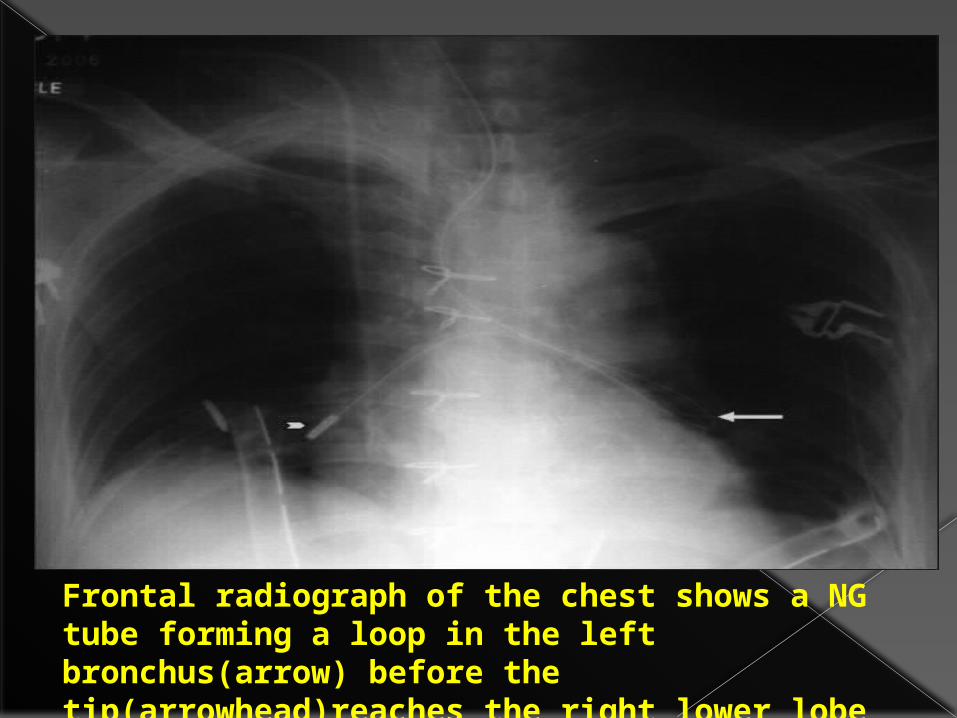
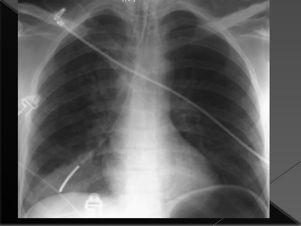
Frontal radiograph of the chest shows a NG tube forming a loop in the left bronchus(arrow) before the tip(arrowhead)reaches the right lower lobe bronchus
Intercostal Chest Drains These are used to remove fluid or air within
the pleural space
Main indications for insertion› Pneumothorax
Tension Simple pneumothorax unresponsive to
aspiration Pnemothorax in a patient with chronic lung
disease› Drainage of pleural fluid
Pleural effusion Haemothorax

Optimum position of drain This depends on why the drain is
being inserted:› Pneumothorax
Towards lung apex (superiorly)
› Pleural fluid drainage Towards cardiophrenic border (inferiorly)

Bilateral chest drainsThis patient has bilateral chest drains, inserted following pneumothoraces secondary to rib fractures.
Note surgical emphysema. Both drains lie towards the apex, but the left drain is coiled and should be withdrawn a little .
The pneumothoraces are not visible on this film.

Problems with Chest Drains
These mostly occur with drain placement› Pain, damage to neurovascular bundle› Trauma to liver, spleen, lung› Drainage ports
These must lie within the chest or there is a risk of surgical emphysema and drain failureDrainage hole correctly
sited within chest

Chest x-ray showing malpositioned intercostal drainage tube in a case of pneumo-thorax with collapse on right side

Chest x-ray showing malpositioned intercostal drainage tube in a case of pleural effusion on left side
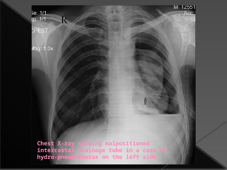
Chest X-ray showing malpositioned intercostal drainage tube in a case of hydro-pneumothorax on the left side
What are the common lines?
•Central venous catheters
• pulmonary artry catheter
•Cardiac Pacemaker

Central Venous Catheters Uses:
› Rapid fluid replacement› Monitoring of central venous pressure› Administration of some drugs
May be inserted from either subclavian or internal jugular vein
The tip should lie within the superior vena cava

Where is the Superior Vena Cava?
Lateral to thoracic spine, inferior to medial end of right clavicle
Figures copyright Primal Pictures 1993
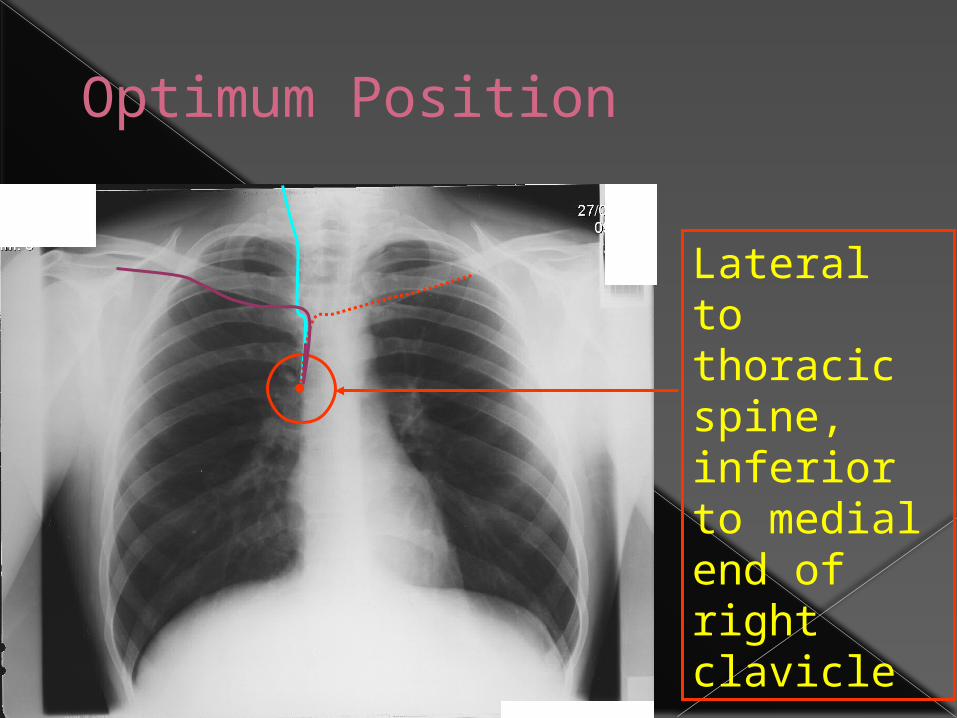
Optimum Position
Lateral to thoracic spine, inferior to medial end of right clavicle


Where the ideal site of catheter tip?
Ideally the catheter tip should lie between the most proximal venous valves of the subclavian or jugular veins and the right atrium.How far from the brachiocephalic vein are these valves?•1. 15 cm•2. 10 cm•3. 5 cm•4. 2.5 cm
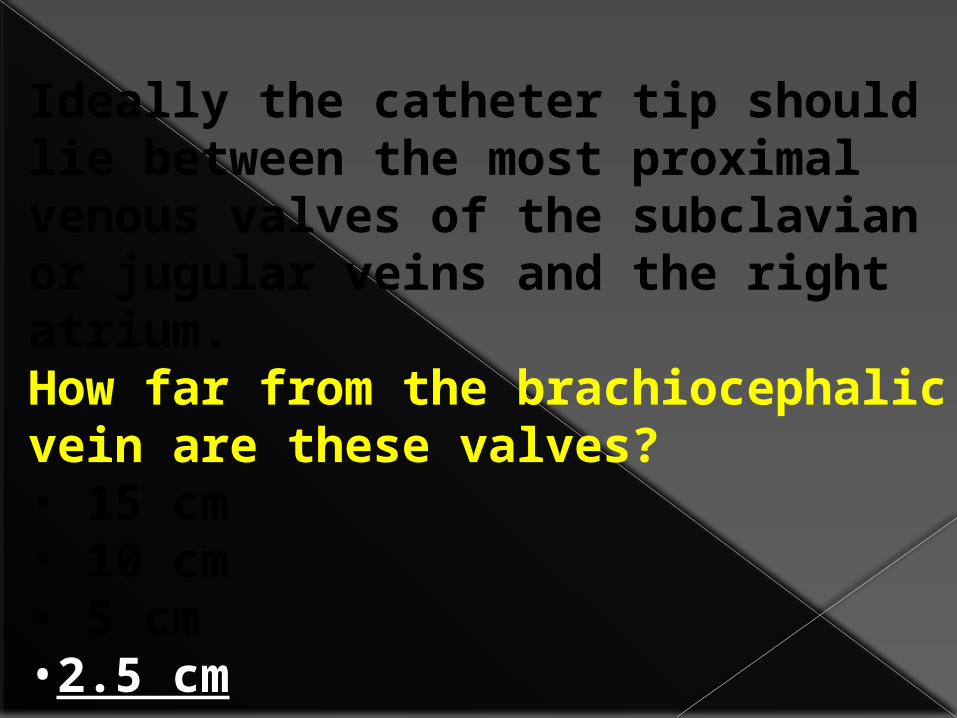
Ideally the catheter tip should lie between the most proximal venous valves of the subclavian or jugular veins and the right atrium.How far from the brachiocephalic vein are these valves?• 15 cm• 10 cm• 5 cm•2.5 cm

The tip of the line should be distal to the last venous valve,which is located 2.5cm from the j unction of the internal jugular and the subclavian veins.
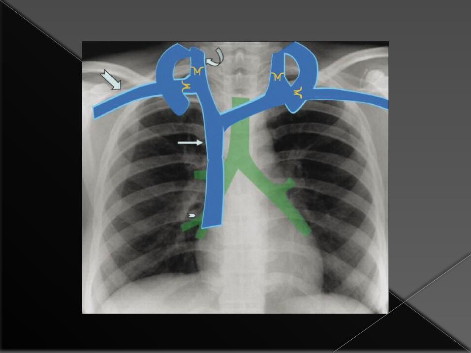
On the CXR, the position of the valve correspond s to the inner aspect of the first rib.

Many central venous lines have two or three lumens,each with adifferent orifice.If the tip of the line is positioned in the superior vena cava all orifices will bedistal to the lastvalve.
On the CXR,the first anterior intercostal space corresponds to the approximate site of the junction of the brachiocephalic veins to form the superior vena cava

On the CXR, the cavo atrial junction correspond s to the lower border of bronchus intermedius.If the line tip reaches the right atrium,it can caused bys arhythmia or result in injection of undiluted toxic medications into the heart.

Right internal jugular venous line in good position (red arrow)
The tip of this left internal jugular venous line lies at the origin of the SVC (green arrow)

Incorrect placement of central line 1A central venous line inserted into the right subclavian vein has passed up into the right
internal jugular vein

Incorrect placement of central line 2
Left internal jugular venous line. The tip lies too inferiorly, within the right atrium (white arrow) and
should be withdrawn to the SVC (green arrow)

Frontal chest radiograph following placement of a central venous catheter shows right paratracheal soft tissue with abulging contour(arrows),due to
mediastinal hematoma.

Frontal chest radiograp h shows an abnormally medial course of the catheter(arrows)in acase of inadvertent carotid cannulation

Pulmonary Artery Wedge Pressure Measurement
This may be performed following cardiac surgery and in patients with severe cardiac / pulmonary dysfunction
The approach is usually via the right internal jugular vein
The catheter passes through the SVC, the right atrium, the right ventricle and the tip lies within a pulmonary artery

The tip of the pulmonary artery wedge pressure catheter lies within the right pulmonary artery
This patient has had recent
cardiac surgery (note sternotomy
wires)

What other lines can you see?
Answer next slide…

Cardiac Pacemakers Used to treat conduction abnormalities
Pacemakers may be single chamber (pacing lead embedded in right ventricular wall) or dual chamber (second lead embedded in right atrial wall)
They are usually inserted via subclavian veins

Dual Chamber Cardiac Pacemaker
Pacemaker
Pacing leads in left subclavian
veinLeads in
superior vena cava
Right ventricular
lead
Right atrial lead
Note that there are no sharp bends in the leads
Problems with Pacemakers At insertion:
› Pneumothorax› Vascular trauma› Cardiac wall puncture
Delayed› Lead migration› Lead fracture
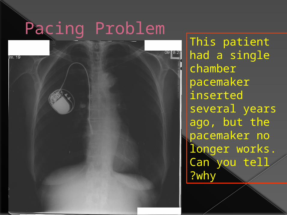
Pacing ProblemThis patient had a single chamber pacemaker inserted several years ago, but the pacemaker no longer works. Can you tell why?

Misplaced pacing lead
The ventricular lead has become detached
and now lies coiled within the right
atrium. It should lie in the region of the red
circle

AGENDA1-tubes
2-lines3-air in chest
4-fluid in chest5-vascular pedicles

In the supine patient, intr apleural air rises anteriorly and medially, often making the diagnosis of pneumothorax difficult.
The anteromedial and subpulmonary locations are the initial areas of air collection in the supine patient.An apical pneumothorax in a supine patient is a sign that a large volume of air is present.
Subpulmonic pneumothorax occurs when air accumulates between the base of the lung and the diaphragm.
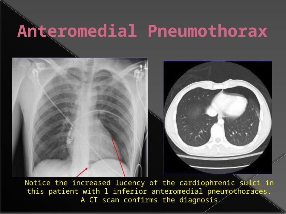
Anteromedial Pneumothorax
Notice the increased lucency of the cardiophrenic sulci in this patient with l inferior anteromedial pneumothoraces. A CT scan confirms the
diagnosis

subpulmonic pneumothorax
a hyperlucent upper quadrant with visualization of the superior surface of the diaphragm and visualization of the inferiorvena cava.
double-diaphragm sign

Deep sulcus sign
Antero lateral air may increase the radiolucency at the costo phrenicsulcus. This is called the deep sulcus sign.

Apicolateral pneumothorax Apicolateral
pneumothorax (arrows) with right upper lobe collapse (arrowheads)

Tension pneumothorax
shifting of the heart border, the superior vena cava, and the inferior vena cava. The shifting of these structures can lead to decreased venous
return.

•Mediastinal shifT is usually seen in a tension pneumothorax.
• The use of PEEP may prevent this from occurring.
•The most reliable sign of tension pneumothorax is depression of a hemidiaphragm.
Tension pnemothorax

•A tension pneumothorax In the ICU patient is a clinical diagnosis based on ventilatory and cardiac compromise.
Radiographically, a tension pneumothorax In an ICU patient can b e an extremely challenging diagnosis.
Parenchymal disease such as ARDS may reduce lung compliance such that to lung collapse in the face of a tension pneumothorax may not occur

Pneumomediastinum
In the intubated patient the most likely source of air in the mediastinum is pulmonary interstitial air dissecting centripetally.
Air in the mediastinum may also originate from tracheobronchial injury or air dissecting through fascial planes from the retroperitoneum.
A sudden increase in thoracic pressures (e.g. blunt trauma) may also cause alveolar rupture and consequently pneumomediastinum

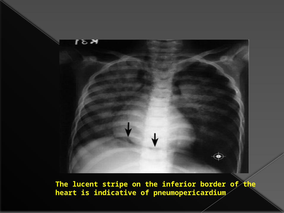
The lucent stripe on the inferior border of the heart is indicative of pneumopericardium

•Notice the lucencies around the great vessels and superior vena cava seen on both AP chest film (left) and CT (right). •Patients with posteromedial pneumomediastinum (usually due to esophageal rupture) may have dissecting air at the paraspinal costophrenic angle and beneath the parietal pleura of the left diaphragm. This is called the V-sign of Naclerio.

The ches t Xray is als o not always Useful for the diagnosis of a pneumothorax in a ventilated patient in the ICU.
In such a patient the air in the pleura l space tends to accumulate anterior to the lung in the supine position,causing it not to be seen on an AP view X-ray.

In addition, mechanically ventilated lungs do not collapse even in the presence of a pneumothorax.
For these reasons ,X-rays have a sensitivity of only53% in detecting pneumothoracesIn such critically ill patients as compared to the gold standar CT
Ultrasound compares favourably with CT scan in the diagnostic ability for some disease conditions ,most prominently pneumothorax, where it has a sensitivity of 92%compared to CT.
For these reasons,ultrasound is fast becoming an essential part of the chest imagin garmamentarium in the ICU

Algorithm for the ultrasound diagnosis of pneumothorax
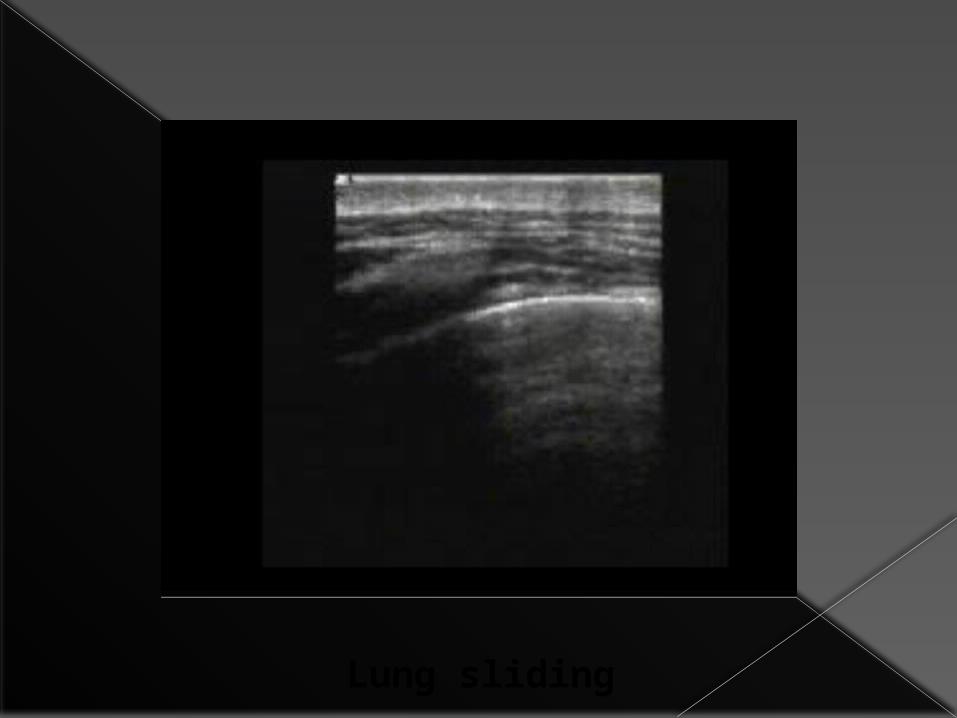
Lung sliding


B lines


The granular pattern below the pleural line in the left half of the picture is lung parenchyma, while the horizontall ines above it
indicate the chest n
1-tubes2-lines
3-air in chest4-fluid in chest
AGENDA

•The appearance of apleural effusion on a chest film is largely Dependent on the position of the patient.
Fluid in the chest cavity will accumulate in the dependent areas of the chest.
This makes idenitifing small collections extremely difficult ,especially in t the supine patient.

Fluid in the posterior basilar space appears as an homogenous graded increase in the density of the lung base,maximal inferiorly.
The normal bronchovascular markings are not lost.
As the amount of fluid increases ,the diaphragmatic contour and lateral costophrenic sulcus may be obliterated.

This patient has large bilateral
effusions; notice the
density gradient in
each lung field
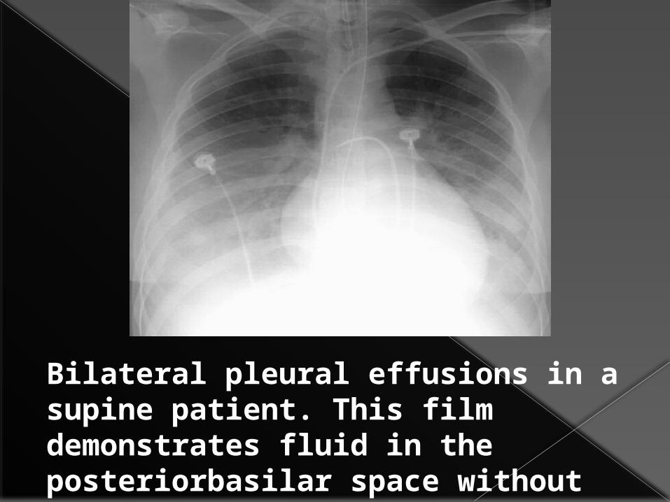
Bilateral pleural effusions in a supine patient. This film demonstrates fluid in the posteriorbasilar space without loss of normal bronchialmarkings.
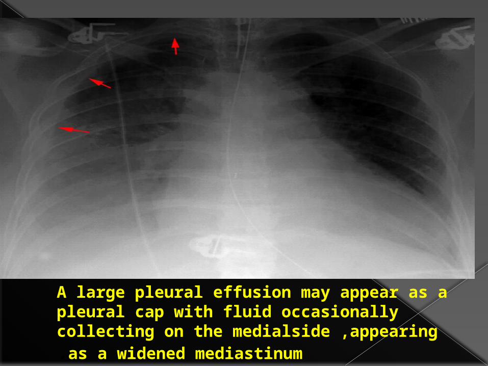
A large pleural effusion may appear as a pleural cap with fluid occasionally collecting on the medialside ,appearing as a widened mediastinum.

How much fluid must accumulate before you expect to see changes in the supine patient's chestx-ray?
1.5 ml2.50 ml3.>500 ml
How much fluid must accumulate before you expect to see changes in the supine patient's chestx-ray?
1.5 ml2.50 ml3.>500 m

How much fuid must collect before costo phrenic blunting is visible in the erect patient?
1.20 ml2.50-75 ml
3.100-200ml4>.500ml

How much fuid must collect before costo phrenic blunting is visible in the erect patient?
1.20 ml2.50-75 ml
3.100-200ml4>.500ml

Howmuchfuidmustcollectbeforecostophrenicbluntingisvisibleinthe
erectpatient?1.20 ml
2.50-75 ml3.100-200ml
4>.500ml
This Pa chest film of an erect patient shows a large Pleural effusion on the right. Even an effusion this size may be difficult to detect in a supine film.

Pleural fluid (arrows) layers out on this left lateral decubitis film.


Pulmonary vascular width

USING VASCULAR PEDICLE WIDTH

VASCULAR PEDICLE WIDTH AND FLUID STATUS IN PULMONARY OEDEMA

QUIZ TIME

AtelectasisThe most common cause of lung opacity in an ICU patient.
There is an increased incidence after general anesthesia and thoracic/upper abdominal surgery .
The incidence is also increased in patients with pre-existing lung disease, smokers, obese patients, and the elderly .
The left lower lobe is the most common location.

Radiographically, atelectasis may vary from complete lung collapse to relatively normal-appearing lungs
Mild atelectasis usually takes the form of minimal basilar shadowing or linear streaks (subsegmental or "discoid" atelectasis) and may not be physiologically significant .
.lobe follows when collapsing.

Atelectasis• Atelectasis will often respond to increased
ventilation, while pneumonia, for example, will not.
• Crowding of vessels, shifting of structures such as interlobar fissures towards areas of lung volume loss and elevation of the hemidiaphragm suggests atelectasis.
• Another key for distinguishing between atelectasis and consolidation is recognition of the typical patterns that each pulmonary

Left lower lobe atelectasis with lost of the hemidiaphragmatic shadow (arrows).

The arrows point to the horizantal fissure. Notice the normal position of the pulmonary arteries in this patient.
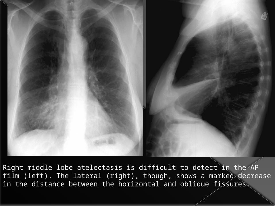
Right middle lobe atelectasis is difficult to detect in the AP film (left). The lateral (right), though, shows a marked decrease in the distance between the horizontal and oblique fissures.

Left Upper Lobe Atelectasis
•The result is predominantly anterior shift of the upper lobe in left upper lobe collapse,
• loss of the left upper cardiac border.
• The expanded lower lobe will migrate to a location both superior and posterior to the upper lobe in order to occupy the vacated space.
• The left mainstem bronchus also rotates to a nearly horizontal position.

left upper lobe atelectasis following right upper lobectomy.

Pneumonia in the ICU
In a supine patient who has aspirated, where are the common locations of pneumonia?
1-Posterior segment of upper lobe
2-Superior segment of lower lobe
3-Basilar segment of lower lobe
4-Apex

pneumonia first appears as• patchy opacifications or ill-defined nodules. • multifocal and bilateral, •often in the gravity dependent areas of the lung. E-coli and pseudomonas species can rapidly involve the entire lung. Their symmetric pattern often simulates pulmonary edema. The presence of patchy air space opacities, air bronchograms, ill-defined segmental consolidation or associated pleural effusion support the diagnosis of pneumonia.
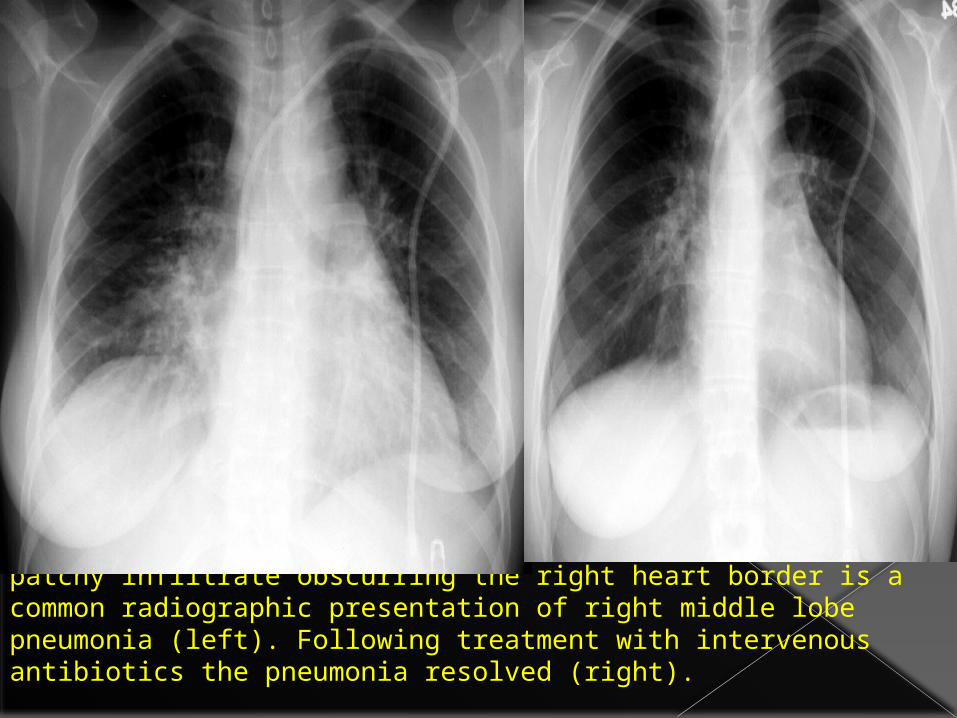
patchy infiltrate obscurring the right heart border is a common radiographic presentation of right middle lobe pneumonia (left). Following treatment with intervenous antibiotics the pneumonia resolved (right).

Aspiration Aspiration is very common in ICU patients.
Aspiration and its consequences can be divided into 3 forms: 1- Aspiration pneumonitis, 2- aspiration pneumonia, 3- obstruction of a central airway.• The severity of aspiration is related to the volume and type of the aspirate.

This patient suffered a witnessed aspiration during intubation. This film was taken 24 hours later. Note the patchy infiltrates maximal at the left base.

Aspiration of gastric acid is also known as Mendelson's Syndrome, it is the most common type of aspiration.
The degree of irritation to the lung is directly dependent on the acidity and volume of the aspirated fluid.
The lung responds to pH < 2.5 with severe bronchospasm and the release of inflammatory mediators. The initial result is a chemical pulmonary edema.

Pulmonary EmbolismThese include •discoid atelectasis, •elevation of the hemidiaphragm,•enlargement of the main pulmonary artery "sausage" or a "knuckle" (Palla's sign),•pulmonary oligemia beyond the point of occlusion (Westermark's sign). Occasionally, pulmonary embolisms will cause• infarction causing a unique constellation of radiographic signs.
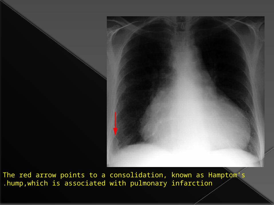
The red arrow points to a consolidation, known as Hamptom's hump,which is associated with pulmonary infarction.


Oligemia (Westermark's sign) Increase in hilar vessel size with abrupt tapering(Knuckle sign) Volume loss


Cardiogenic oedema VS ARDS•Features that are helpful in distinguishing CHF from ARDS include the following:•cardiogenic pulmonary edema typically begins centrally in the bilateral perihilar areas, • Pleural effusions are not typical of ARDS but often present in CHF. •Kerley B lines are common in CHF but not in ARDS,

•cardiogenic edema may clear rapidly, ARDS typically clears slowly.
• cardiogenic edema, which, once resolved, does not leave behind permanent pulmonary changes.
• ARDS cases will result in some degree of permanent pulmonary fibrosis,

اليك اتوب و استغفرك انت اال اله ال ان اشهد بحمدك و اللهم سبحانك