chilled ceilings i - rehau · acoustic chilled ceilings and high-performance acoustic chilled...
TRANSCRIPT

CHILLED CEILINGS ITechnical manual including Acoustic chilled ceilings

1
This Technical Information concerning acoustic chilled ceilings and chilled ceilings is valid from June, 2013.
This supersedes the previous Technical Information 860602 (Edition May 2012).
Our current Technical Information is available for down-loading at www.rehau.com.
This document is protected by copyright. All associated rights, in particular with respect to translation, reprinting, the reproduction of illustrations, telecommunications, reproduction on photomechanical or similar equipment, and data storage in data processing equipment, remain reserved.
All dimensions and weights are intended as reference.We reserve the right to correct errors and make changes.
Due to a system conversion to SAP in 2012, our article numbers have changed to material numbers.
The previous article numbers have become material numbers with 2 extra digits: old: 123456-789 (article number)new: 11234561789 (material number)To illustrate this in the catalogue, we have visually identi-fied the additional digits: 1 = 1, e.g.: 11234561789
Please note that in the system all quotations, order confir-mations, dispatch notes and invoices will largely only be issued with the 11-digit number.

2
CONTENTS
1 � � � � � INFORMATION AND SAFETY INSTRUCTIONS� � � � � � � � � 4
2 � � � � � ACOUSTIC CHILLED CEILINGS � � � � � � � � � � � � � � � � 52.1 . . . . System description . . . . . . . . . . . . . . . . . . . . . . 52.1.1 . . . System components . . . . . . . . . . . . . . . . . . . . . 52.1.2 . . . Usable pipes . . . . . . . . . . . . . . . . . . . . . . . . . 52.1.3 . . . Description . . . . . . . . . . . . . . . . . . . . . . . . . . 62.1.4 . . . Application areas . . . . . . . . . . . . . . . . . . . . . . . 62.1.5 . . . Overview of acoustic chilled ceiling program for perforation
patterns 6/18 R, 8/18 R and 8/18 Q . . . . . . . . . . . . . 72.1.6 . . . Acoustic chilled ceiling with 6/18 R perforation pattern. . . . . 82.1.7 . . . Acoustic chilled ceiling with 8/18 R perforation pattern. . . . 102.1.8 . . . Acoustic chilled ceiling with 8/18 Q perforation pattern. . . . 122.1.9 . . . Ceiling sail . . . . . . . . . . . . . . . . . . . . . . . . . 142.1.9.1 . . Description . . . . . . . . . . . . . . . . . . . . . . . . . 142.1.9.2 . . Areas of application. . . . . . . . . . . . . . . . . . . . . 142.1.9.3 . . Ceiling sail 8/18 R and 8/18 Q . . . . . . . . . . . . . . . 142.1.10. . . Connecting elements . . . . . . . . . . . . . . . . . . . . 142.1.11. . . Optional insulation - Mineral wool in accordance
with DIN 13162. . . . . . . . . . . . . . . . . . . . . . . 142.2 . . . . Mounting . . . . . . . . . . . . . . . . . . . . . . . . . . 152.2.1 . . . Ambient site conditions . . . . . . . . . . . . . . . . . . . 152.2.2 . . . Storage. . . . . . . . . . . . . . . . . . . . . . . . . . . 152.2.3 . . . Transport . . . . . . . . . . . . . . . . . . . . . . . . . . 162.3 . . . . Installation process . . . . . . . . . . . . . . . . . . . . . 162.3.1 . . . Overview of installation process . . . . . . . . . . . . . . . 162.3.2 . . . Mounting of the distribution pipeline network . . . . . . . . 162.3.3 . . . Substructures . . . . . . . . . . . . . . . . . . . . . . . 162.3.4 . . . Preparations for ceiling element installation . . . . . . . . . 172.3.5 . . . Alignment and fastening of the chilled ceiling elements . . . 172.3.6 . . . Rinsing, filling and de-aerating . . . . . . . . . . . . . . . 192.3.7 . . . Inactive ceiling areas . . . . . . . . . . . . . . . . . . . . 192.3.8 . . . Spackling. . . . . . . . . . . . . . . . . . . . . . . . . . 192.3.9 . . . Surface grinding, edge alignment . . . . . . . . . . . . . . 202.3.10. . . Subsurface . . . . . . . . . . . . . . . . . . . . . . . . . 202.3.11. . . Primer . . . . . . . . . . . . . . . . . . . . . . . . . . . 202.3.12. . . Paints and lacquers . . . . . . . . . . . . . . . . . . . . . 202.3.13. . . Locating pipes transporting media . . . . . . . . . . . . . . 202.4 . . . . Joints and connections . . . . . . . . . . . . . . . . . . . 212.4.1 . . . Movement joint . . . . . . . . . . . . . . . . . . . . . . . 212.4.2 . . . Wall connection. . . . . . . . . . . . . . . . . . . . . . . 21
3 � � � � � CHILLED CEILINGS� � � � � � � � � � � � � � � � � � � � � 223.1 . . . . System description . . . . . . . . . . . . . . . . . . . . . 223.1.1 . . . System components . . . . . . . . . . . . . . . . . . . . 223.1.2 . . . Usable pipes . . . . . . . . . . . . . . . . . . . . . . . . 223.1.3 . . . Description . . . . . . . . . . . . . . . . . . . . . . . . . 223.1.4 . . . Application areas . . . . . . . . . . . . . . . . . . . . . . 223.2 . . . . Mounting . . . . . . . . . . . . . . . . . . . . . . . . . . 243.2.1 . . . Ambient site conditions . . . . . . . . . . . . . . . . . . . 243.2.2 . . . Storage. . . . . . . . . . . . . . . . . . . . . . . . . . . 243.2.3 . . . Installation process . . . . . . . . . . . . . . . . . . . . . 243.3 . . . . Surface treatment . . . . . . . . . . . . . . . . . . . . . 273.3.1 . . . Subsurface . . . . . . . . . . . . . . . . . . . . . . . . . 273.3.2 . . . Primer . . . . . . . . . . . . . . . . . . . . . . . . . . . 273.3.3 . . . Wallpaper and plasters . . . . . . . . . . . . . . . . . . . 273.3.4 . . . Paints and lacquers . . . . . . . . . . . . . . . . . . . . . 283.3.5 . . . Locating pipes transporting media . . . . . . . . . . . . . . 283.4 . . . . Joints and connections . . . . . . . . . . . . . . . . . . . 283.4.1 . . . Floating wall connection . . . . . . . . . . . . . . . . . . 283.4.2 . . . Movement joint . . . . . . . . . . . . . . . . . . . . . . . 29
4 � � � � � PLANNING � � � � � � � � � � � � � � � � � � � � � � � � � 304.1 . . . . Planning principles . . . . . . . . . . . . . . . . . . . . . 304.2 . . . . Heating/Cooling capacity . . . . . . . . . . . . . . . . . . 304.3 . . . . Sound absorption . . . . . . . . . . . . . . . . . . . . . . 304.4 . . . . Planning example of a ceiling field based on an acoustic chilled
ceiling . . . . . . . . . . . . . . . . . . . . . . . . . . . 304.5 . . . . Connection . . . . . . . . . . . . . . . . . . . . . . . . . 314.6 . . . . Joint planning principles . . . . . . . . . . . . . . . . . . 314.7 . . . . Control technology . . . . . . . . . . . . . . . . . . . . . 324.8 . . . . Comfort . . . . . . . . . . . . . . . . . . . . . . . . . . 324.9 . . . . Degassing . . . . . . . . . . . . . . . . . . . . . . . . . 32

3
Notes on this Technical Information
ValidityThis Technical Information applies to COUNTRY.
Applicable Technical Information - Technical Information, Underfloor heating/cooling - Technical Information, System principles, pipes and joints
NavigationAt the beginning of this Technical Information you can find a detailed table of contents with hierarchical titles and corresponding page numbers.
Pictograms and logos
Safety instructions
Legal information
Important information which has to be observed
Information on the Internet
The advantages for you
Up-to-dateness of the Technical InformationFor your own safety and for the correct application of our products please check at regular intervals whether a newer version of your Technical Informa-tion is availablet. The issue date of your Technical Information is always printed on the bottom left-hand side of the cover page.You can obtain the current Technical Information from your REHAU sales office, specialist distributor or you can download it from the Internet at:www.rehau.com or www.rehau.com/downloads.
Safety instructions and operating instructions - For your own safety and the safety of other people, please read through all safety instructions and operating instructions carefully before commencing assembly.
- Keep the operating instructions safe and have them available. - If you have not understood the safety instructions or the individual assembly instructions or find them unclear, please contact your REHAU sales office.
- Failure to comply with the safety instructions can result in damage to property or personal injury.
Use in line with the specificationThe acoustic chilled ceilings and chilled ceilings may only be planned, ins-talled and operated as described in this Technical Information. Any other use is not in accordance with the specification and is therefore not permitted.
Observe all applicable national and international regulations relating to laying, assembly, safety and the prevention of accidents when installing pipe systems as well as the instructions in this Technical Information.Areas of application not covered in this Technical Information (special applica-tions) require consultation with our technical applications department. Please contact your REHAU sales office for a comprehensive consultation.
Personnel requirements - Our systems should only be installed by people who are authorised to do so and have received training in this.
- Work on electrical installations or pipeline components should only be carried out by qualified and authorised persons.
General precautions - Keep your workplace tidy and free of obstructions. - Make sure there is always sufficient light in your workplace. - Keep children, pets and unauthorised persons away from tools and the assembly area. This applies particularly to renovations in inhabited areas.
- Only use the components intended for that particular REHAU pipe system. The use of components from other systems or the use of tools that are not part of the relevant REHAU assembly system may result in accidents or other risks.
- Avoid open flames in the work area.
Working clothes - Wear protective goggles, suitable working clothes, safety shoes, a hard hat and a hairnet if you have long hair.
- Do not wear loosely fitting clothes or jewelry as they may get caught in moving parts.
- Wear a hard hat when carrying out assembly work at head height or above your head.
During assembly - Always read and follow the operating instructions for the REHAU assembly tool used.
- The REHAU pipe cutters have a sharp blade. Store and handle them in such a way that there is no risk of injury from the pipe cutters.
- When trimming the pipes, maintain a safe distance between the hand holding the pipe and the cutting tool.
- Never put your hand in the tool‘s cutting zone or on moving parts during the cutting process.
- Following the expansion process, the expanded pipe shrinks back to its original shape (memory effect). Do not insert any foreign objects into the expanded pipe during this stage.
- Never put your hand in the tool‘s compression zone or on moving parts during the compression process.
- Until the connection is established following the compression process, the fitting can fall out of the pipe. There is a risk of injury!
- During maintenance or retooling work and when changing the assembly area, always unplug the tool and prevent it from being switched on acciden-tally.
1 INFORMATION AND SAFETY INSTRUCTIONS
4
2 ACOUSTIC CHILLED CEILINGS
2�1 System description
- High cooling output of up to 79 W/m² - High sound absorption effect of αw up to 0.80 - Suited for heating and cooling - Four board sizes offer high configuration levels - Three different perforation patterns offer high design flexibility - Stable sandwich construction offers outstanding handling - Simple assembly thanks to predrilled fixing grid with thermally active ceiling elements
- Preassembled ceiling element permits short installation times
2�1�1 System components
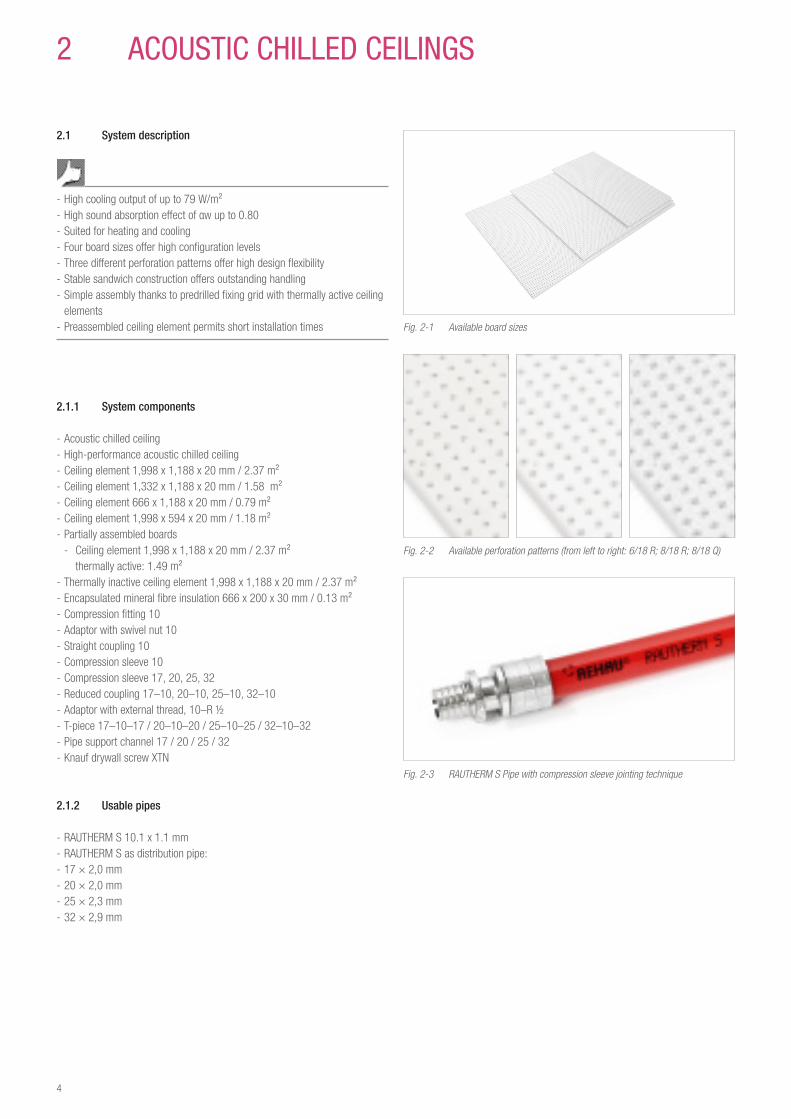
- Acoustic chilled ceiling - High-performance acoustic chilled ceiling - Ceiling element 1,998 x 1,188 x 20 mm / 2.37 m² - Ceiling element 1,332 x 1,188 x 20 mm / 1.58 m² - Ceiling element 666 x 1,188 x 20 mm / 0.79 m² - Ceiling element 1,998 x 594 x 20 mm / 1.18 m² - Partially assembled boards
- Ceiling element 1,998 x 1,188 x 20 mm / 2.37 m² thermally active: 1.49 m²
- Thermally inactive ceiling element 1,998 x 1,188 x 20 mm / 2.37 m² - Encapsulated mineral fibre insulation 666 x 200 x 30 mm / 0.13 m² - Compression fitting 10 - Adaptor with swivel nut 10 - Straight coupling 10 - Compression sleeve 10 - Compression sleeve 17, 20, 25, 32 - Reduced coupling 17–10, 20–10, 25–10, 32–10 - Adaptor with external thread, 10–R ½ - T-piece 17–10–17 / 20–10–20 / 25–10–25 / 32–10–32 - Pipe support channel 17 / 20 / 25 / 32 - Knauf drywall screw XTN
2�1�2 Usable pipes
- RAUTHERM S 10.1 x 1.1 mm - RAUTHERM S as distribution pipe: - 17 × 2,0 mm - 20 × 2,0 mm - 25 × 2,3 mm - 32 × 2,9 mm
Fig. 2-1 Available board sizes
Fig. 2-2 Available perforation patterns (from left to right: 6/18 R; 8/18 R; 8/18 Q)
Fig. 2-3 RAUTHERM S Pipe with compression sleeve jointing technique

5
Acou
stic
chi
lled
ceili
ngs
2�1�3 Description
Basically, the acoustic chilled ceilings and high-performance acoustic chilled ceilings, together with the thermally inactive ceiling elements are made from line-production gypsum plasterboards in accordance with DIN 18180/DIN EN 520 and DIN EN 14190 respectively, and with or without integrated graphite.The acoustic chilled ceiling and the high-performance acoustic chilled ceiling are made of two perforated gypsum plasterboards, bonded together so that the perforation patterns are precisely aligned with one another. Grooves have been milled into the gypsum plasterboards. Into these, the prefabricated, white, RAUTHERM 10.1 x 1.1 mm S Pipe is integrated in loops with a pipe distance of 36 mm. A layer of black, acoustic fleece is laminated on the rear side. The composite structure formed by the gypsum plasterboard and the acoustic fleece ensures simple assembly, a uniform overlay as well as providing a high level of stiffness. The 4 different ceiling element sizes ensure high coverage rates for both the active cooling surface as well as the active acoustic surface even in rooms with special shapes.The 4 sharp edges / 4 SK and the pre-drilled fixing grid allow an easy installa-tion of the ceiling surface.
The acoustic chilled ceiling and the high-performance acoustic chilled ceiling are available with the following perforation patterns:
Perforationpatterndesignation
Perforationpatternappearance
Perforationgeometry
Perforationdiameter
Perforationspacing(center-center)
6/18 R regular round 6 mm 18 mm8/18 R regular round 8 mm 18 mm8/18 Q regular square 8 mm 18 mm
Tab. 2-1 Perforation patterns
2�1�4 Application areas
Acoustic chilled ceilings and high-performance acoustic chilled ceilings are intended for the construction of suspended ceiling surfaces and for use inside buildings.
Acoustic chilled ceilings and high-performance acoustic chilled ceilings having a five reaction classification: Class B s2 d0 in accordance with DIN EN 13501. They are not suitable for fire protection ceilings or as other components with a fire resistance classification of F30 to F90 or higher! Requirements with respect to preventative and structural fire protection in escape or emergency routes must be complied with!
Acoustic chilled ceilings and high-performance acoustic chilled ceilings may be employed in commercial areas, in office and administration buildings without moisture loading.With the exception of washrooms and toilet areas without showers, the system is not suited for employment in moist areas of any type, such as in commer-cial wet rooms, saunas and pools.

6
2�1�5 Overview of acoustic chilled ceiling program for perforation patterns 6/18 R, 8/18 R and 8/18 Q
Ceiling element [L x W] Designation DimensionsL x W x H [mm]
Element area [m²]
Thermally active area [m²]
Large element 1,998 × 1,188 × 20 2,37 2,26
Medium element 1,132 × 1,188 × 20 1,58 1,49
Small element 666 × 1,188 × 20 0,79 0,73
Large element(connecting element)
1,998 × 1,188 × 20 2,37 without
1/2 element(half width)
1,998 × 594 × 20 1,18 1,10
Large elementThermally partially activated
⅔ active - ⅓ inactive
1,998 × 1,188 × 20 2,37 1,49
Large elementThermally partially activated
⅓ inactive - ⅔ active
1,998 × 1,188 × 20 2,37 1,49
Tab. 2-2 Overview of acoustic chilled ceiling range for perforation patterns 6/18 R, 8/18 R and 8/18 Q

7
Acou
stic
chi
lled
ceili
ngs
2�1�6 Acoustic chilled ceiling with 6/18 R perforation pattern
Fig. 2-4 6/18 R perforation pattern
Ceiling type Unit Acoustic chilled ceiling High-performance acoustic chilled ceilingStandard cooling capacity in accordance with DIN EN 14240 (8K)1)
W/m² 58.1 63.2
Standard cooling capacity in accordance with DIN EN 14240 (10 K)1)
W/m² 73.8 80.1
Standard heating capacity based on DIN EN 14037 (10 K)1)
W/m² 56.7 60,3
Standard heating capacitybased on DIN EN 14037 (15 K)1)
W/m² 85.5 90.7
Assessed sound absorption level αw in accordance with ISO 11654
– 0,45 (LM) or 0,50 (L)4) 0,45 (LM) or 0,50 (L)4)
Sound absorption class in accordance with ISO 11654
– D or D4) D or D4)
Noise Reductions Coefficient (NRC) in accordance with ASTM C423
– 0,60 or 0,604) 0,60 or 0,604)
Fire reaction classificationin accordance with DIN EN 13501
– B-s2, d0 B-s2, d0
Element surface area m² 2,37 1,58 0,79 2,37 1,58 0,79Thermally active element surface m² 2,26 1,49 0,73 2,26 1,49 0,73Lenght2) (longitudinal edge) mm 1,998 1,332 666 1,998 1,332 666Width²) (transverse edge) mm 1,188 1,188 1,188 1,188 1,188 1,188Thickness2) mm 20 20 20 20 20 20Element weight kg 38,0 25,3 12,7 38,0 25,3 12,7Pipe length m 60 40 20 60 40 20Element pressure loss at m = 25 kg/m²·h Pa
(mbar)20,300 (203)
7,000 (70)
1,100 (11)
20,300 (203)
7,000 (70)
1,100 (11)
Element cooling output (8 K)3) W 131 87 42 143 94 46Element cooling output (10 K)3) W 167 110 54 181 119 58Element heating output (10 K)3) W 128 84 41 136 90 40Element heating output (15 K)3) W 193 127 62 205 135 66
1 In accordance with the heating/cooling capacity standard, all values are based on 1 m2 of active surface area.2 The specified dimensions and tolerances are compliant with the requirements of DIN EN 5203 Heating/cooling capacity of the total element surface area4 The first value represents the sound absorption without a mineral fibre insulation backing layer, the second value represents the sound absorption with an encapsulated, 30 mm mineral fibre insulation layer on the rear side.
·

8
Cooling capacity in accordance with DIN EN 14240The cooling capacity is based on a 1 m² active cooling area.
Sound absorption in accordance with DIN EN ISO 354, without mineral fibre backing layer
Suspended height 200 mm
Assessed sound absorption level αw = 0.45 (LM) in accordance with ISO 11654Sound absorption class in accordance with ISO 11654: DVerbal assessment in accordance with VDI 3755: AbsorbingNoise Reduction Coefficient (NRC) in accordance with ASTM C423: 0.60Sound Absorbing Average (SAA) in accordance with ASTM C423: 0.59
Heating capacity based on DIN EN 14037The heating capacity is based on a 1 m² active heating area.
Sound absorption in accordance with DIN EN ISO 354, with 30 mm mineral fibre backing layer
Suspended height 200 mm
Assessed sound absorption level αw = 0.50 (L) in accordance with ISO 11654Sound absorption class in accordance with ISO 11654: DVerbal assessment in accordance with VDI 3755: AbsorbingNoise Reduction Coefficient (NRC) in accordance with ASTM C423: 0.60Sound Absorbing Average (SAA) in accordance with ASTM C423: 0.61

9
Acou
stic
chi
lled
ceili
ngs
2�1�7 Acoustic chilled ceiling with 8/18 R perforation pattern
Fig. 2-5 8/18 R perforation pattern
Ceiling type Unit Acoustic chilled ceiling High-performance acoustic chilled ceilingStandard cooling capacity in accordance with DIN EN 14240 (8K)1)
W/m² 56,5 62,2
Standard cooling capacity in accordance with DIN EN 14240 (10 K)1)
W/m² 71,9 79,0
Standard heating capacity based on DIN EN 14037 (10 K)1)
W/m² 56,3 60,6
Standard heating capacitybased on DIN EN 14037 (15 K)1)
W/m² 86,2 92,4
Assessed sound absorption level αw in accordance with ISO 11654
– 0,65 (L) bzw. 0,754) 0,65 (L) bzw. 0,754)
Sound absorption class in accordance with ISO 11654
– C bzw. C4) C bzw. C4)
Noise Reductions Coefficient (NRC) in accordance with ASTM C423
– 0,70 bzw. 0,704) 0,70 bzw. 0,704)
Fire reaction classificationin accordance with DIN EN 13501
– B-s2, d0 B-s2, d0
Element surface area m² 2,37 1,58 0,79 2,37 1,58 0,79Thermally active element surface m² 2,26 1,49 0,73 2,26 1,49 0,73Lenght2) (longitudinal edge) mm 1,998 1,332 666 1,998 1,332 666Width2) (transverse edge) mm 1,188 1,188 1,188 1,188 1,188 1,188Thickness2) mm 20 20 20 20 20 20Element weight kg 36,0 24,0 12,0 36,0 24,0 12,0Pipe length m 60 40 20 60 40 20Element pressure loss at m = 25 kg/m²·h Pa
(mbar)20,300 (203)
7,000 (70)
1,100 (11)
20,300 (203)
7,000 (70)
1,100 (11)
Element cooling output (8 K)3) W 128 84 41 141 93 45Element cooling output (10 K)3) W 162 107 52 179 118 58Element heating output (10 K)3) W 127 84 41 137 90 44Element heating output (15 K)3) W 195 128 63 209 138 67
1 In accordance with the heating/cooling capacity standard, all values are based on 1 m2 of active surface area.2 The specified dimensions and tolerances are compliant with the requirements of DIN EN 5203 Heating/cooling capacity of the total element surface area4 The first value represents the sound absorption without a mineral fibre insulation backing layer, the second value represents the sound absorption with an encapsulated, 30 mm
mineral fibre insulation layer on the rear side.

10
Cooling capacity in accordance with DIN EN 14240The cooling capacity is based on a 1 m² active cooling area.
Sound absorption in accordance with DIN EN ISO 354, without mineral fibre backing layer
Suspended height 200 mm
Assessed sound absorption level αw = 0.65 (L) in accordance with ISO 11654Sound absorption class in accordance with ISO 11654: CVerbal assessment in accordance with VDI 3755: Highly absorbingNoise Reduction Coefficient (NRC) in accordance with ASTM C423: 0.70Sound Absorbing Average (SAA) in accordance with ASTM C423: 0.71
Heating capacity based on DIN EN 14037The heating capacity is based on a 1 m² active heating area.
Sound absorption in accordance with DIN EN ISO 354, with 30 mm mineral fibre backing layer
Suspended height 200 mm
Assessed sound absorption level αw = 0.75 in accordance with ISO 11654Sound absorption class in accordance with ISO 11654: CVerbal assessment in accordance with VDI 3755: Highly absorbingNoise Reduction Coefficient (NRC) in accordance with ASTM C423: 0.70Sound Absorbing Average (SAA) in accordance with ASTM C423: ) 0.73

11
Acou
stic
chi
lled
ceili
ngs
2�1�8 Acoustic chilled ceiling with 8/18 Q perforation pattern
Fig. 2-6 8/18 Q perforation pattern
Ceiling type Unit Acoustic chilled ceiling High-performance acoustic chilled ceilingStandard cooling capacity in accordance with DIN EN 14240 (8K)1)
W/m² 52,2 57,0
Standard cooling capacity in accordance with DIN EN 14240 (10 K)1)
W/m² 66,2 72,2
Standard heating capacity based on DIN EN 14037 (10 K)1)
W/m² 52,4 55,9
Standard heating capacity based on DIN EN 14037 (15 K)1)
W/m² 79,0 84,1
Assessed sound absorption level αw in accordance with ISO 11654
– 0,70 bzw. 0,804) 0,70 bzw. 0,804)
Sound absorption classin accordance with ISO 11654
– C bzw. B4) C bzw. B4)
Noise Reductions Coefficient (NRC) in accordance with ASTM C423
– 0,70 bzw. 0,754) 0,70 bzw. 0,754)
Fire reaction classification in accordance with DIN EN 13501
– B-s2, d0 B-s2, d0
Element surface area m² 2,37 1,58 0,79 2,37 1,58 0,79Thermally active element surface m² 2,26 1,49 0,73 2,26 1,49 0,73Length2) (longitudinal edge) mm 1,998 1,332 666 1,998 1,332 666Width2) (transverse edge) mm 1,188 1,188 1,188 1,188 1,188 1,188Thickness2) mm 20 20 20 20 20 20Element weight kg 36,0 24,0 12,0 36,0 24,0 12,0Pipe length m 60 40 20 60 40 20Element pressure loss at m = 25 kg/m²·h Pa
(mbar)20,300 (203)
7,000 (70)
1,100 (11)
20,300 (203)
7,000 (70)
1,100 (11)
Element cooling output (8 K)3) W 118 78 38 129 85 42Element cooling output (10 K)3) W 150 99 48 163 108 53Element heating output (10 K)3) W 118 78 38 126 83 41Element heating output (15 K)3) W 179 118 58 190 125 61
1 In accordance with the heating/cooling capacity standard, all values are based on 1 m² of active surface area.2 The specified dimensions and tolerances are compliant with the requirements of DIN EN 5203 Heating/cooling capacity of the total element surface area4 The first value represents the sound absorption without a mineral fibre insulation backing layer, the second value represents the sound absorption with an encapsulated, 30 mm mineral fibre insulation layer on the rear side.
·

12
Cooling capacity in accordance with DIN EN 14240The cooling capacity is based on a 1 m² active cooling area.
Sound absorption in accordance with DIN EN ISO 354, without mineral fibre backing layer
Suspended height 200 mm
Assessed sound absorption level αw = 0.70 in accordance with ISO 11654Sound absorption class in accordance with ISO 11654: CVerbal assessment in accordance with VDI 3755: Highly absorbingNoise Reduction Coefficient (NRC) in accordance with ASTM C423: 0.70Sound Absorbing Average (SAA) in accordance with ASTM C423: 0.72
Heating capacity based on DIN EN 14037The heating capacity is based on a 1 m² active heating area.
Sound absorption in accordance with DIN EN ISO 354, with 30 mm mineral fibre backing layer
Suspended height 200 mm
Assessed sound absorption level αw = 0.80 in accordance with ISO 11654Sound absorption class in accordance with ISO 11654: BVerbal assessment in accordance with VDI 3755: Highly absorbingNoise Reduction Coefficient (NRC) in accordance with ASTM C423: 0.75Sound Absorbing Average (SAA) in accordance with ASTM C423: 0.74

13
Acou
stic
chi
lled
ceili
ngs
2�1�9 Ceiling sail
2�1�9�1 Description
Fig. 2-7 Ceiling sail edge finish
The basis of the ceiling sails with an acoustic chilled ceiling or high-perfor-mance acoustic chilled ceiling is formed by gypsum plasterboard finished on a production line to DIN 18180 / DIN EN 520 and DIN EN 14190 with or without graphite. The edge finish of the sails freely suspended in the room can be designed for example with folded gypsum plasterboard set on edge. The cool-ing capacity can be increased by 15 – 20 % with this open design.
2�1�9�2 Areas of application
The acoustic chilled ceiling and the high-performance acoustic chilled ceiling as sails is suitable for use in offices and meeting rooms with exposed concrete surfaces, glass elements or reverberant floors. The flexible arrangement of the sails has the advantage that the lighting and ventilation can be placed in any position between the ceiling sails in particular during renovations. This is an advantage in situation of modifications.
2�1�9�3 Ceiling sail 8/18 R and 8/18 Q
Heated/chilled ceiling type Unit AKD sail 8/18 R H-AKD sail 8/18 RStandard cooling capacity to DIN EN 14240 (8 K)1)
W/m² 69,4 72,9
Standard cooling capacity to DIN EN 14240 (10 K)1)
W/m² 87,6 92,3
Standard heating capacity based on DIN EN 14037 (15 K)1)
W/m² 112,6 120,0
Heated/chilled ceiling type Unit AKD sail 8/18 Q H-AKD sail 8/18 QStandard cooling capacity to DIN EN 14240 (8 K)1)
W/m² 67,1 71,6
Standard cooling capacity to DIN EN 14240 (10 K)1)
W/m² 85,0 90,4
Standard heating capacity based on DIN EN 14037 (15 K)1)
W/m² 113,2 121,0
1) The values refer to 1 m2 active surface
Tab. 2-3
Prior to fastening the edge finishes, it has to be ensured that the pipes inte-grated in the ceiling elements will not be damaged.
2�1�10 Connecting elements
Fig. 2-8 Available, thermally inactive elements
Thermally inactive ceiling elements can be employed in conjunction with the matching perforation pattern of the acoustic chilled ceiling type.
Suitable for chilled ceiling type
Acoustic chilled ceiling High-performance acoustic chilled ceiling
Perforation pattern 6/18 R 8/18 R 8/18 Q 6/18 R 8/18 R 8/18 QElement surface area (m²) 2,37 2,37Length (mm) 1998 1998Width (mm) 1188 1188Thickness (mm) 20 20Element weight (kg) 44,0 42,0 42,0 44,0 42,0 42,0
Tab. 2-4 Connecting Elements
The graphite inclusions in the high-performance acoustic chilled ceiling result in a colour difference in the perforation pattern of the acoustic chilled ceiling. If daylight shines as grazing light the color difference becomes apparent as a difference between pale and dark grey. To avoid this colour difference, a cor-responding matching selection between the thermal inactivated element and the associated chilled ceiling type must be made.
Connecting elements can either be manually cut into shape using an appropri-ate handsaw, or can be mechanically cut, using an appropriate radial saw. Regardless of which method is employed, we strongly recommend using a guide rail to ensure a straight cut.
The connecting elements don’t have a predrilled fixing grid.
2�1�11 Optional insulation - Mineral wool in accordance with DIN 13162
Fig. 2-9 PE-encapsulated mineral fibre

14
Applying an additional, encapsulated mineral fibre backing to the acoustic chilled ceiling or the high-performance acoustic chilled ceiling provides an improved sound absorption level.
Technical characteristics Units Data StandardLenght mm 666 –Width mm 200 –Height mm 30 –Weight kg 0,070 –Rated thermal transfer ability (λ)
W/(mK) 0,040 –
Applications – DI DIN 4108-10Mineral fibre construction class – A1 DIN EN 13501-1Fire classification of the mineral fibre in conjunction with PE sheeting
– E DIN EN 13501
PE sheeting thickness μm ca. 25 –Flow resistance, MF kPas/m² ≥ 5 (AF 5) –Thickness tolerance class – T2 DIN EN 13162
The mineral fibre is enclosed in PE sheeting to prevent fibre flight.
The insulation material is loosely applied flat, on the rear side of the acoustic chilled ceiling or high-performance acoustic chilled ceiling and between the substructure bearers.
Avoid storage in direct sunlight.
2�2 Mounting
2�2�1 Ambient site conditions
Many years of experience have shown that the ideal installation conditions for working with gypsum plasterboards are a relative humidity of between 40 % and 80 % and room temperatures above +5 °C.
Cladding using products based on gypsum plasterboards should not be performed when the ambient humidity in the structure exceeds 80 % for extended periods.
After installation, the acoustic chilled ceiling and high-performance acoustic chilled ceiling must be protected against the long-term effects of humidity. Therefore, the structure must be adequately ventilated once assembly has been completed. Directly blowing on the ceiling surface with either hot or cold air is to be avoided. If hot asphalt is intended to provide the screed, spackling may only be carried out once the screed has cooled. Rapid, sudden heat increases in the winter are to be avoided, as these could result in changes in length, tension fractures or bulging on the ceiling surface.
Particularly plastering and screed work results in drastic increases in relative humidity. Thorough ventilation must be provided for these situations, particu-larly in conjunction with dry construction moistened.
The acoustic chilled ceiling and high-performance acoustic chilled ceiling must be prevented from getting completely moistened.
2�2�2 Storage
Acoustic chilled ceiling, high-performance acoustic chilled ceiling elements and accessories must be protected against the effects of humidity and sunlight. Basically, all gypsum products must be stored in dry areas. To avoid deformations and breakage, the acoustic chilled ceiling and high-performance acoustic chilled ceiling elements should be stored flat, e.g., on pallets or sup-port blocks, spaced approx. 35 cm apart. Improper storage of chilled ceiling elements, such as, for example, in an upright position, will result in deforma-tion and damage to corners and edges, impeding proper assembly.
Fig. 2-10 Delivery and storage of acoustic chilled ceiling elements
When storing boards indoors, note the structure‘s ceiling load bearing capac-ity. Twenty acoustic chilled ceiling elements measuring 1,998 x 1,188 x 20 mm have a weight in total of approx. 800 kg.
The elements must be stored with the black fleece facing upwards.

15
Acou
stic
chi
lled
ceili
ngs
2�2�3 Transport
Acoustic chilled ceiling elements are delivered on pallets. On site they must be kept upright and moved by two individuals, or using suitable methods of transport. When carried manually, the ceiling elements should be slightly tilted, with hands placed at least 10 cm away from the board edge.
The elements must be carried with the fleece-covered side “up”.
Fig. 2-11 Manual handling of acoustic chilled ceiling elements at the site
2�3 Installation process
2�3�1 Overview of installation process
1. Mounting of the distribution network on the ceiling slab2. Preparation of the substructure3. Mounting of the active ceiling elements on the substructure4. Connection of the ceiling elements to the distribution pipes5. Rinsing and performing the pressure test6. If required, complete insulation of the distribution and connecting pipes7. Mounting of the inactive ceiling areas8. Spackling the joints and screw heads9. Treating the ceiling surface
2�3�2 Mounting of the distribution pipeline network
Before the acoustic chilled ceiling elements can be installed, the pipe system must first be suspended below the ceiling slab, preferably utilizing the Tichel-mann system. When performing this task, make sure not to come into contact with the hangers on which the metal substructure will be suspended.
Fig. 2-12 Distribution pipeline network
We recommend a vapor-proof insulation for the connecting lines, in order to avoid water condensation.
2�3�3 Substructures
In accordance with DIN 18181, acoustic chilled ceiling and high-performance acoustic chilled ceiling elements are designed to be installed on metal sub-structures. Substructures based on metal profiles must be designed as metal substructures (refer to Fig. 2-12 and 2-13).We recommend CD profiles 60 x 27 x 0.6 mm for metal substructure designs.
The suspended metal substructure consisting of Nonius hangers, CD profiles and connecting anchors must be capable of bearing the approx. 16 kg/m2 weight of the installed acoustic chilled ceiling or high-performance acoustic chilled ceiling elements.
Fig. 2-13 Suspended metal substructure lying parallel to the longitudinal edge of the board
Allowable spans:
Hanger a 750 mmBasic profile b 750 mmSupport battens c 297 mm parallel to the longitudinal edge of the board
Fig. 2-14 Suspended metal substructure lying parallel to the transverse edge of the board
Allowable spans:
Hanger a 750 mmBasic profile b 750 mmSupport battens c 333 mm parallel to the transverse edge of the board

16
Examples of suspended metal substructure:
So-called “Nonius” hangers with two securing splints are particularly well-suited for installation of the metal substructures. The securing splints must be designed so that they prevent independent slipping.
So-called “anchors” are recommended, in order to secure the base profile to the support battens.
Anchor and attachment hardware approved for the specific applications and loads involved are employed to attach these substructures to solid ceilings. Connections between metal base and support battens must be made using appropriate accessory components from the CD profile manufacturer. Details concerning their design can be found in the individual construction technology documentation prepared by the CD profile manufacturer.
The substructure support profiles must always lie parallel to the board edges.
2�3�4 Preparations for ceiling element installation
1. Prepare pipework for connection to the supply lines. Lengthen pipes with coupler and RAUTHERM S pipe 10.1 x 1.1 mm if necessary.
Fig. 2-15 Preparing the pipework
2. Grind the edges on the visible side so that a slight chamfer is formed.
Fig. 2-16 Grinding the edges
3. Prime edges with the “Knauf Tiefengrund” primer from Knauf Co.
Please see the literature of the manufacturer Knauf for further information on handling the primer
Fig. 2-17 Priming edges
2�3�5 Alignment and fastening of the chilled ceiling elements
Make sure the elements are laid in a uniform direction. The boards are marked red and blue at the cutting edges. A red board mark must always be fitted to a blue board mark when assembling.

17
Acou
stic
chi
lled
ceili
ngs
Fig. 2-18 Alignment of the ceiling elements
1 assembly aid, according to perforation pattern
2 additional visual inspection
The ceiling elements are aligned with each other using an assembly aid cor-responding to the perforation pattern. The alignment of the perforation pattern must always be inspected visually in addition.
Fig. 2-19 Jointing
The optimum joint width is 2 mm to 4 mm. The minimum joint width of 2 mm may not be exceeded because otherwise the joint cannot be filled up to the full joint height of 20 mm.
Mounting the chilled ceiling elementsFor installation we recommend a mechanical board lifter when installingacoustic chilled ceiling or high-performance acoustic chilled ceiling elements.
Fig. 2-20 Board lifter to correctly position the ceiling elements
The chilled ceiling elements (acoustic chilled ceiling and high-performance acoustic chilled ceiling) may only be fastened with the Knauf drywall screw XTN or equivalent with the following features in the pre-drilled holes on the visible side: - Screw length: 33 mm - Diameter: 3,9 mm - Head form: flat head (8 mm diameter) - Screw tip: rolled - Coating: black phosphatized - Thread type: double-flighted thread
Use approx. 25 screws per m2, support battens parallel to the transverse edge.
We recommend the employment of a drywall screwdriver with a depth stop.
Fig. 2-21 Installation, using a drywall screwdriver with depth stop
Screw holes outside the indicated fixing grid points can damage the fabricated 10.1 x 1.1 mm RAUTHERM S pipe. Ceiling elements are installed with the continuous visible board side face inwards into the room.
If the acoustic chilled ceiling or high-performance acoustic chilled ceiling elements are installed in such a way that the suspended metal construc-tion’s support battens lie parallel to the longitudinal edge of the board, every predrilled hole in the attachment grid should be filled with a drywall screw suitable to the chilled ceiling type. If the ceiling elements are installed parallel to the short end, every second perforation row along the short edge must be filled with a drywall screw suitable to the chilled ceiling type.
18
The hydraulic connection is made by the heating technician after assembly of the thermally active chilled ceiling elements.
2�3�6 Rinsing, filling and de-aerating
Rinsing must occur immediately after the installation of the active acoustic chilled ceiling elements. At the conclusion of filling, - hydraulic compensation of the individual pipe sections (if the Tichelmann system was employed) or
- the separate heating circuits (if connected directly to a manifold) must be carried out.
Venting the air bubbles from the system requires that a minimum volume flow rate must be established. This flow rate is 0.8 l/min, corresponding to a speed of 0.2 m/sec.
Pressure testThe pressure test must be performed once the air has been ventilated from the system. It must be carried out and documented in accordance with the pressure test profile set forth in the Technical Information, “Underfloor heat-ing/cooling”. Where a freezing risk exists, appropriate steps should be taken to prevent the system from being damaged by freezing. These can include, for example, structure heating or the employment of an antifreeze agent.
Pressure test reports can be downloaded at www.rehau.com/downloads.
The de-aeration of the system and subsequent pressure testing are vital to commissioning the acoustic chilled ceiling or high-performance acoustic chilled ceiling.
The connecting lines must be insulated as required and encapsulated mineral wool insulation laid on the ceiling elements if necessary.
2�3�7 Inactive ceiling areas
Thermal inactivated areas may be clad with thermal inactivated elements. These are to be selected based on the employed chilled ceiling, so that their design and their perforation pattern match.
Fig. 2-22 Example of the inclusion of an air outlet in a thermally inactive element
Thermally inactive ceiling areas can be finished off, using commercially avail-able gypsum plasterboards or perforated gypsum plasterboards. Care should be taken to ensure that the 20 mm assembly height of the acoustic chilled ceiling or high-performance acoustic chilled ceiling boards is maintained. In these areas, the weight-bearing of the associated substructure must be adequate.
Assembly elements such as, for example, integrated lighting, air vents or sprinklers, may only be installed in thermally inactive areas of the ceiling. This must be taken into account in a timely manner while the ceiling surface is being planned.Hanging lamps may not be installed on acoustic chilled ceiling or high-perfor-mance acoustic chilled ceiling boards.Suitable measures must be taken to ensure that hanging lamps are either suspended from the base ceiling or are fixed to the substructure without exceeding the maximum load capacity. Additional basic profiles and support batten profiles must be considered in this section of the substructure.
When planning the inclusion of built-in elements, it may be necessary to create safety zones to the acoustic chilled ceiling elements. Please note the requirements provided by the assembly element manufacturers.
Due the graphite integrated into its gypsum matrix, high-performance acoustic chilled ceiling boards are electrically conductive. On the one hand, this can lead to faulty currents if an integrated lamp is improperly installed. On the other hand, a certain shielding effect with regard to electromagnetic radiation may also be present.
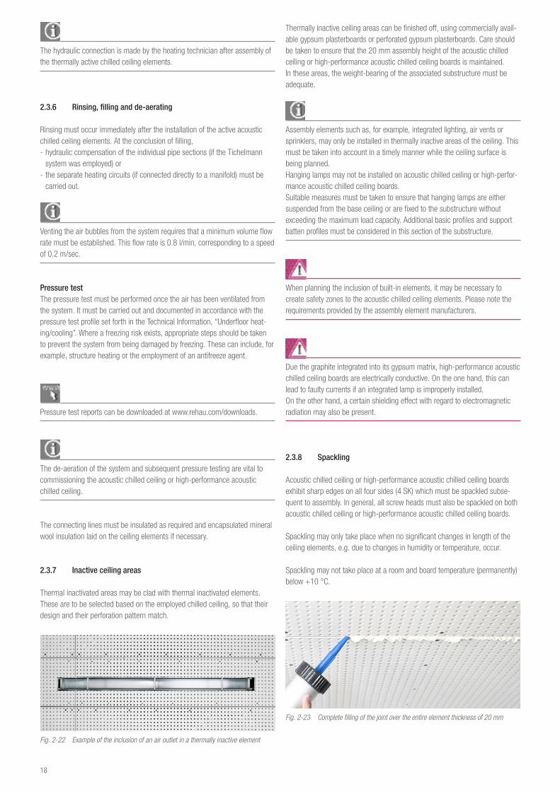
2�3�8 Spackling
Acoustic chilled ceiling or high-performance acoustic chilled ceiling boards exhibit sharp edges on all four sides (4 SK) which must be spackled subse-quent to assembly. In general, all screw heads must also be spackled on both acoustic chilled ceiling or high-performance acoustic chilled ceiling boards.
Spackling may only take place when no significant changes in length of the ceiling elements, e.g. due to changes in humidity or temperature, occur.
Spackling may not take place at a room and board temperature (permanently) below +10 °C.
Fig. 2-23 Complete filling of the joint over the entire element thickness of 20 mm

19
Acou
stic
chi
lled
ceili
ngs
The joint must be filled with “Knauf Uniflott” up to the full height of the ceiling element thickness of 20 mm.See the literature of the manufacturer Knauf for details on handling the spackling compound.
Fig. 2-24 Removing hardened spackle
Fig. 2-25 Screw head spackling
Spackling of the perforation pattern in thermally active ceiling elements is not permitted.
2�3�9 Surface grinding, edge alignment
After spackling, the spackled joints and screw heads must be grounded. This can be done manually, using sandpaper with grain sizes 100 to 200.
Fig. 2-26 Surface grinding
2�3�10 Subsurface
The subsurface, which is, the side of the acoustic chilled ceiling or high-performance acoustic chilled ceiling facing the room and including the joints, must comply with the requirements for surface levelness as set forth in DIN 18202. Beyond this, it must also be dry, load bearing and free of dust and dirt.
2�3�11 Primer
Prior to any additional coats of paint being applied, the acoustic chilled ceil-ing or high-performance acoustic chilled ceiling boards, together with the spackled areas, must be primed. Primer helps balance out the absorption differences between gypsum plasterboard and joint spackle.If interior dispersion paint is applied directly to gypsum plasterboards, absorp-tion differences can result in colour variations and shadowing. Attempts to correct such differences by repainting can result in paint cracks.
Primer may only be applied with a suitable roller or brush. We do not recom-mend the employment of a paint spray gun.
2�3�12 Paints and lacquers
Most commercially available emulsion paints can be used.
Mineral-based paints such as, for example, lime, mineral and silicate paints are not suitable.
Fig. 2-27 Using a roller for painting
Paint may only be applied with a suitable roller or brush. We do not recom-mend the employment of a paint spray gun.
2�3�13 Locating pipes transporting media
Using thermal sheeting, pipes carrying media can be located during a warm-up process. For this, the thermal sheeting is placed on the area being examined, after which the warm-up process is carried out on the acoustic chilled ceiling or high-performance acoustic chilled ceiling. Thermal sheeting can be reused several times.

20
Fig. 2-28 Using thermal sheeting to locate pipes transporting media
2�4 Joints and connections
Joints and connections must already be considered during the planning phase. Joint planning principles can be found in Section 4.7.The following structural and planning principles must be considered:
- The employment of expansion or movement joints on the ceiling surface must provide the same degree of movement as the structure’s moving joints.
- DIN 18181 requires that ceiling surfaces be interrupted in both the lon-gitudinal as well as the transverse directions every 10 m by expansion or movement joints.
- Suspended ceiling cladding must be structurally separated from integrated supports and assembly components such as, for example, lamps.
- Wherever the cross-section changes to a marked degree, for example, due to hallway widening or jutting walls, the ceiling surface must be equipped with joints.
When acoustic chilled ceiling or high-performance acoustic chilled ceiling boards are installed, the following joint or connection types may arise.
2�4�1 Movement joint
The entire ceiling structure must be separated in the area surrounding a movement joint. A movement joint is employed to bridge structural joints in the building’s corpus, or if the ceiling length necessitates a subdivision into sections. This is required at least every 10 m for the acoustic chilled ceiling or high-performance acoustic chilled ceiling.
Fig. 2-29 Design example field joint (moving joint)
1 Acoustic chilled ceiling or high-performance acoustic chilled ceiling
2 Perforated or non-perforated connecting element
3 Cover profile
4 Metal substructure / CD profile
2�4�2 Wall connection
Wall connections between acoustic chilled ceiling or high-performance acoustic chilled ceiling boards and room enclosing surfaces must always be expanding, so that the temperature-related horizontal expansion of the ceiling elements can be compensated for by these joints.
Fig. 2-30 Example of a floating wall connection
Fig. 2-31 Fig. 2.30 Design example floating wall connection
Fig. 2-32 Design example wall connection with stepped connecting element
1 Acoustic chilled ceiling or high-performance acoustic chilled ceiling
2 Perforated or non-perforated connecting element
3 Shadow gap
4 Metal substructure / CD profile
5 U connection profile / UD 30
6 Connection seal (alternative)
7 Stepped connecting element

21
Acou
stic
chi
lled
ceili
ngs
3 CHILLED CEILINGS
3�1 System description
- High capacity output of up to 76 W/m² - Suited for heating and cooling - Four board sizes offer high configuration levels - Stable sandwich construction offers outstanding handling - Simple assembly thanks to predrilled fixing grid - Preassembled ceiling element permits short installation times
3�1�1 System components
- Chilled ceiling - High-performance chilled ceiling - Ceiling element 2,000 x 1,250 x 30 mm / 2.5 m² - Ceiling element 1,500 x 1,250 x 30 mm / 1.88 m² - Ceiling element 1,000 x 1,250 x 30 mm / 1.25 m² - Ceiling element 500 x 1,250 x 30 mm / 0.63 m² - Compression fitting 10 - Adaptor with union nut 10 - Straight coupling 10 - Compression sleeve 10 - Compression sleeve 17, 20, 25, 32 - Reduced coupling 17–10, 20–10, 25–10, 32–10 - Adaptor with male thread, 10–R ½ - T-piece 17–10–17 / 20–10-20 / 25–10–25 / 32–10–32 - Pipe support channel 16 / 17 / 20 / 25 / 32 - Rigips Climafit drywall screw TN Gold
3�1�2 Usable pipes
- RAUTHERM S 10.1 x 1.1 mm - RAUTHERM S as distribution pipe:
- 17 × 2,0 mm - 20 × 2,0 mm - 25 × 2,3 mm - 32 × 2,9 mm
Fig. 3-1 Chilled ceiling for dry construction
Fig. 3-2 Available board sizes
3�1�3 Description
Basically, the chilled ceiling and high-performance chilled ceiling are made from line-production gypsum plasterboards in accordance with DIN 18180/DIN EN 520 respectively, and with or without integrated graphite. The chilled ceiling and high-performance chilled ceiling are gypsum plasterboards with grooves milled into them and RAUTHERM S 10.1 x 1.1 mm pipes with a 45 mm laying gap integrated in a loop pattern. A backing made of EPS 035 polystyrene insulation; together with gypsum reinforcement strips ensure easy installation. Ceiling elements in four different sizes ensure high coverage rates for active cooling areas, even in non-uniformly sized rooms. Inactive areas on the ceiling surface can be closed using commercially available 15 mm gyp-sum plasterboards in a double cladding design. The half-round, flattened edge (HRAK) on the sides parallel to the applied reinforcing strips allows the ceiling surface to be easily manufactured.
3�1�4 Application areas
Chilled ceilings and high-performance chilled ceilings are intended for the construction of suspended ceiling surfaces and for use inside buildings.
Chilled ceilings and high-performance chilled ceilings possess Class B s1, d0 fire behaviour characteristics in accordance with DIN EN 13501. They are not suitable for employment as fire protection ceilings or as other components with a fire resistance classification of F30 to F90 or higher! Requirements with respect to preventative and structural fire protection in escape or emergency routes must be complied with!
The ceiling elements can be employed in domestic and commercial areas such as office and administration buildings without moisture loading. With the exception of washrooms and toilet areas without showers, the system is not suited for employment in moist areas of any type, such as in commercial wet rooms, saunas and pools.

22
Ceiling type Unit Chilled ceiling High-performance chilled ceilingStandard cooling capacity in accordance with DIN EN 14240 (8K)1)
W/m² 51,7 59,9
Standard cooling capacity in accordance with DIN EN 14240 (10 K)1)
W/m² 66,0 75,5
Standard heating capacity based on DIN EN 14037 (10 K)1)
W/m² 53,3 59,9
Standard heating capacity based on DIN EN 14037 (15 K)1)
W/m² 82,6 92,7
Fire reaction classification in accordance with DIN EN 13501
– B-s1, d0 B-s1, d0
Element surface area m² 2,50 1,88 1,25 0,63 2,50 1,88 1,25 0,63Thermally active element surface m² 2,10 1,60 1,00 0,50 2,10 1,60 1,00 0,50Length2) mm 2000 1500 1000 500 2000 1500 1000 500Width2) mm 1250 1250 1250 1250 1250 1250 1250 1250Thickness) mm 30 30 30 30 30 30 30 30Element weight kg 42,5 32,0 21,0 10,7 41,3 30,9 20,6 10,3Pipe length m 48 37 23 11 48 37 23 11Element pressure loss m = 25 kg/m²·h Pa
(mbar)17.800 (178)
8.500 (85)
2.700 (27)
415 (4)
17.800 (178)
8.500 (85)
2.700 (27)
415 (4)
Element cooling output (8 K)3) W 108 83 52 26 126 96 60 30Element cooling output (10 K)3) W 138 105 66 33 158 121 75 38Element heating output (10 K)3) W 112 85 53 27 126 96 60 30Element heating output (15 K)3) W 173 132 82 41 194 148 93 46
1 In accordance with the heating/cooling capacity standard, all values are based on 1 m2 of active surface area.2 The specified dimensions and tolerances are compliant with the requirements of DIN EN 520.3 Heating/cooling capacity of the total element surface area
Cooling capacity in accordance with DIN EN 14240The cooling capacity is based on a 1 m² active cooling area.
Heating capacity based on DIN EN 14037The heating capacity is based on a 1 m² active heating area.
·

23
Chill
ed c
eilin
gs
3�2 Mounting
3�2�1 Ambient site conditions
Many years of experience have shown that the ideal installation conditions for working with gypsum plasterboards are a relative humidity of between 40 % and 70 % and room temperatures above +10 °C.
Cladding using products based on gypsum plasterboards should not be performed when the ambient humidity in the structure exceeds 80 % for extended periods.
After installation, the ceiling elements must be protected against the long-term effects of humidity. Therefore, the structure must be adequately ventilated once assembly has been completed. Directly blowing on the ceiling surface with either hot or cold air is to be avoided. If hot asphalt is intended to provide the screed, spackling may only be carried out once the screed has cooled. Rapid, sudden heat increases in the winter are to be avoided, as these could result in changes in length, tension fractures or bulging on the ceiling surface.
Particularly plastering and screed work results in drastic increases in relative humidity. Thorough ventilation must be provided for these situations, particu-larly in conjunction with dry construction work.
3�2�2 Storage
Chilled ceiling, high-performance chilled ceiling boards and accessories must be protected against the effects of humidity. Basically, all gypsum products must be stored in dry areas. To avoid deformations and breakage, the ceiling elements should be stored flat, e.g., on pallets or support blocks, spaced approx. 35 cm apart. Improper storage of chilled ceiling elements, such as, for example, in an upright position, will result in deformation which will impede proper assembly.
When storing boards indoors, note the structure’s ceiling load bearing capac-ity. Twenty ceiling elements measuring 2,000 x 1,250 mm have a weight in total of approx. 850 kg.
3�2�3 Installation process
1. Mounting of the distribution network on the ceiling slab2. Preparation of the substructure3. Mounting of the active ceiling elements on the substructure4. Connection of the ceiling elements to the distribution pipes5. Rinsing and performing the pressure test6. If required, complete insulation of the distribution and connecting pipes7. Mounting of the inactive ceiling areas8. Spackling the ceiling surface9. Treating the ceiling surface
SubstructureIn accordance with DIN 18181, chilled ceiling and high-performance chilled ceiling boards are designed for assembly on metal substructures. Two ver-sions of substructures based on metal profiles can be employed: - Directly attached metal substructure (refer to Fig. 3-3) - Suspended metal substructure (refer to Fig. 3-4)
Substructures in the form of metal substructures must be capable of bearing the approx. 17 kg/m2 weight of the chilled ceiling and high-performance chilled ceiling boards..

24
Fig. 3-3 Directly attached metal substructure in accordance with DIN 18181 Wall connection, refer to Fig. 3-9
Fig. 3-4 Suspended metal substructure in accordance with DIN 18181 Wall connection, refer to Fig. 3-9
Substructure versions Directly attached metal substructure(refer to Fig� 3-3)
Suspended metal substructure(refer to Fig� 3-4)
Hanger a 1000 mm 750 mmBasic profile b entfällt 1000 mmSupport profile c 417 mm
parallel to the longitudinal edge of the board417 mm parallel to the longitudinal edge of the board
Tab. 3-1 Support spans for metal substructures for horizontal surfaces and 10 – 50° roof slopes
CD profiles 60 x 27 x 0.6 mm are recommended for building the metal substructure.
Conventional suspension elements in accordance with DIN 18181, such as Nonius hangers, perforated or slotted strip steel, wire hangers or direct hang-ers can be employed to attach the boards to suspended metal substructures. Anchor and attachment hardware approved for the specific applications and loads involved are employed to secure these substructures to solid ceilings.
Connections between metal base and support battens must be made using appropriate accessory components from the CD profile manufacturer. Details concerning their design can be found in the individual construction technology documentation prepared by the CD profile manufacturer.
For requirements with respect to the different versions of substructures, table 3-3 offers information concerning the dimensions of base and support bat-tens, together with the permissible support spacing.
The support profiles of the substructure must always lie parallel with the installed ceiling elements reinforcing strips. The support profiles may only be installed to the gypsum strip laminated on the upper surface of the chilled ceiling elements.
Fig. 3-5 Installed ceiling element
TransportCeiling elements are delivered on pallets. On site they must be carried upright or moved using suitable methods of transport.
Carrying chilled ceiling elements and high-performance chilled ceiling ele-ments with the polystyrene insulation facing “down” is to be avoided.

25
Chill
ed c
eilin
gs
Mounting the chilled ceiling elementsWe recommend the employment of a mechanical board lifter when installing the ceiling elements. In this way, the chilled ceiling and high-performance chilled ceiling elements can be installed by a single individual.
Only standard drywall screws may be employed to secure the chilled ceiling boards. These must exhibit the following characteristics on the visible side: - Screw length: 55 mm - Nominal diameter: 3,9 mm - Thread type: Coarse thread
Only Rigips Climafit drywall screws TN Gold manufactured by the firm of Rigips may be employed to secure high-performance chilled ceiling elements. These are to be inserted in the predrilled fixing grid on the front face and must have the following characteristics: - Screw length 55 mm - Nominal diameter: 3,9 mm - Head form: trumpet head - Screw tip: rolled - Coating: Ruspert-Gold - Thread type: Coarse thread
Use approx. 20 screws per m².
We recommend the employment of a drywall screwdriver with a depth stop.
Screw holes outside the indicated fastening points can damage the fabricated 10.1 x 1.1 mm RAUTHERM S pipes. Ceiling elements are installed with the continuous visible board side face inwards into the room. Ceiling elements may only be secured with drywall screws in the area of the laminated gypsum strip backing. Installing screws in the area of the laminated polystyrene insula-tion on the back can result in board breakage.
No cross joints may be made when installing the chilled ceiling and the high-performance chilled ceiling elements. A side-offset of at least 400 mm must be maintained.
Fig. 3-6 Proper ceiling elements assembly
1 Insulation
2 Gypsum strips
3 CD profile
Inactive ceiling areasInactive ceiling areas can be finished off using commercially available s = 15 mm gypsum plasterboards, designed as double cladding. The substructure in these areas must be able to support the associated weight
Assembly elements such as, for example, integrated lighting, air vents or sprinklers, may only be installed in thermally inactive areas of the ceiling. This must be taken into account in a timely manner while the ceiling surface is being planned.
When planning the inclusion of built-in elements, it may be necessary to cre-ate safety zones to the chilled ceiling elements. Please note the requirements provided by the assembly element manufacturers.
SpacklingIn general, the half-round, flattened edges of the chilled ceiling or high-performance chilled ceiling elements, together with the screw heads, must be spackled. The transverse board edges must be bevelled and, prior to spackling, must be cleaned with a moist brush or sponge. Basically, all board joints should be free of dust. To prevent cracking, the joints of the ceiling ele-ments must always be designed to include paper reinforcement strips. Prior to spackling, these must be moistened in order to prevent bubbling.
The gypsum plasterboard “LaPlura” made by LaFarge forms the basis for the REHAU chilled ceiling. The gypsum plasterboard “Rigips Climafit” made by Rigips forms the basis for the REHAU high-performance chilled ceiling.Therefore the materials to be used per work step are listed in the table below.
Work step Chilled ceiling High-performance chilled ceiling
1. First spackle application
LaFillfresh B45/B90 VARIO joint spackle or VARIO 30 joint spackle
2. Apply reinforce ment strips
Paper reinforcement strips1)
Glass fibre reinforcement strips
3. Second spackle application
LaFillfresh B45/B90 VARIO joint spackle or VARIO 30 joint spackle
4. As requiredFinish
LaFinish VARIO joint spackle or ProMix Plus
1 To avoid blisters, the paper reinforcement strips must be moistened before applying
Fig. 3-7 Spackling with reinforcement strips

26
Flushing, filling and de-aeratingFlushing must occur immediately after the installation of the active chilled ceiling elements. At the conclusion of filling, hydraulic compensation of the individual pipe sections (if the Tichelmann system was employed) or the sepa-rate heating circuits (if connected directly to a manifold) must be carried out.
Venting the air bubbles from the system requires that a minimum volume flow rate must be established. This flow rate is 0.8 l/min, corresponding to a speed of 0.2 m/sec.
Pressure testThe pressure test must be performed once the air has been ventilated from the system. It must be carried out and documented in accordance with the pressure test report for REHAU underfloor heating/cooling. Where a freezing risk exists, appropriate steps should be taken to prevent the system from be-ing damaged by freezing. These can include, for example, structure heating or the employment of an antifreeze agent.
Pressure test reports can be downloaded at www.rehau.com/downloads.
The de-aerating of the system and subsequent pressure testing are vital to commissioning the chilled ceiling or high-performance chilled ceiling.
3�3 Surface treatment
3�3�1 Subsurface
The subsurface, that is, the side of the ceiling elements facing the room and including the joints, must comply with the requirements for surface levelness as set forth in DIN 18202. Beyond this, it must also be dry, load bearing and free of dust and dirt.
The employment of special wallpaper, shiny coatings, indirect lighting or strip lighting, makes particular demands on the subsurface levelness. In these instances, the entire ceiling surface must be spackled.
The design information related to quality stages Q3 and Q4, respectively, must be strictly adhered to.
3�3�2 Primer
Prior to any additional application of colour or of wallpaper, the ceiling ele-ments and spackled joints must be primed. Primer helps balance out the absorption differences between gypsum plasterboard and joint spackle. If in-terior dispersion paint is applied directly to gypsum plasterboards, absorption differences can result in colour variations and shadowing. Attempts to correct such differences by repainting can result in paint cracks.
3�3�3 Wallpaper and plasters
Before applying wallpaper, we recommend applying a wallpaper primer. This will ease the removal of old wallpaper during subsequent renovations.
Only methyl cellulose adhesives may be employed for wallpapering.

27
Chill
ed c
eilin
gs
3�3�4 Paints and lacquers
Chilled ceiling and high-performance chilled ceiling boards can be coated using plastic-bonded roller and brush plasters. Primers or adhesive coatings based on the manufacturer’s recommendations should be employed for this.
Performance degradations resulting from the application of roller and brush plasters must be taken into account.
Most commercially available emulsion paints can be used. Paint may only be applied with a suitable roller or brush or, after priming, with a paint spray gun.
Mineral-based paints such as, for example, lime, mineral and silicate paints are not suitable.
Any fibres which are not secured by priming must be removed prior to paint application. When coating with lacquer, we recommend the application of two coats. Information regarding special spackling requirements for quality stage Q4 must be strictly complied with.
3�3�5 Locating pipes transporting media
Using thermal sheeting, pipes carrying media can be located during a warm-up process. For this, the thermal sheeting is placed on the area being examined, after which the ceiling elements are commissioned. Thermal sheet-ing can be reused several times.
Fig. 3-8 Using thermal sheeting to locate pipes transporting media
3�4 Joints and connections
Joints and connections must already be taken into account during the plan-ning phase. Joint planning principles can be found in Section 4.7 on pg. 31. The following structural and planning principles must be considered:
- The employment of expansion or movement joints on the ceiling surface must provide the same degree of movement as the structure’s moving joints.
- DIN 18181 requires that ceiling surfaces be interrupted in both the lon-gitudinal as well as the transverse directions every 10 m by expansion or movement joints.
- Suspended ceiling cladding must be structurally separated from integrated supports and assembly components such as, for example, lamps.
- Wherever the cross-section changes to a marked degree, for example, due to hallway widening or jutting walls, the ceiling surface must be equipped with joints..
When chilled ceiling or high-performance chilled ceiling elements are in-stalled, the following joint or connection types may arise.
3�4�1 Floating wall connection
A floating wall connection must be provided between the ceiling elements and the room wall. The temperature-related horizontal expansion of the ceiling elements can be compensated for by these connections. In the area around the floating joint, the ceiling connection profile is visible. The front face of the chilled ceiling and high-performance chilled ceiling can be covered by an edge profile.
The support battens may be spaced up to a maximum distance of 10 cm from the adjacent wall surface.
Fig. 3-9 Floating wall connection
1 Chilled ceiling or high-performance chilled ceiling
2 Metal substructure
3 Edge profile
4 Connection profile
5 Connection seal

28
3�4�2 Movement joint
The entire ceiling structure must be separated in the area surrounding a movement joint. It is employed to bridge structural joints in the building’s corpus, or if the ceiling length necessitates a subdivision into sections. This is required at least every 10 m for the chilled ceiling or high-performance chilled ceiling.
Fig. 3-10 Movement joint (measurements shown in mm)
1 Chilled ceiling or high-performance chilled ceiling
2 Edge profile

29
Chill
ed c
eilin
gs
4 PLANNING
4�1 Planning principles
In order to ensure the proper execution of the acoustic chilled ceiling/high-performance acoustic chilled ceiling or the chilled ceiling/high-performance chilled ceiling elements, ceiling planning must be carried out on the basis of a ceiling plan agreed upon by architects and specialized planners. Ceiling instal-lations such as, for example, lighting, vents or sprinklers must be considered during planning so that the necessary active ceiling areas can be defined for the acoustic chilled ceiling/high-performance acoustic chilled ceiling or chilled ceiling/high-performance chilled ceiling. A timely coordination across trades is essential. Heating and cooling output calculations must be available.
4�2 Heating/Cooling capacity
The heating/cooling capacity of the acoustic chilled ceiling/high-performance acoustic chilled ceiling or chilled ceiling/high-performance chilled ceiling elements are based on DIN EN 14037 for heating and, for cooling, are in ac-cordance with DIN EN 14240. They have been determined by an independent certified testing institute.
Capacity diagrams are available for downloading from the Internet under www.rehau.com/downloads.
For heating, the maximum permissible continuous operating temperature for the acoustic chilled ceiling/high-performance acoustic chilled ceiling or chilled ceiling/high-performance chilled ceiling must be limited to +45 °C. Higher temperatures will result in ceiling element destruction.
4�3 Sound absorption
The sound absorption level was determined by an independent testing institu-tion in accordance with DIN EN ISO 354. An associated assessment of the sound absorption, together with a breakdown into Sound Absorption Classes has been performed in accordance with DIN EN ISO 11654 for the acoustic chilled ceiling and high-performance acoustic chilled ceiling.
Test reports related to sound absorption, together with sound absorptiondiagrams can be downloaded from the Internet at www.rehau.com/downloads.
4�4 Planning example of a ceiling field based on an acoustic chilled ceiling
The positions of the chilled ceiling elements must be considered already in the planning to ensure fast, easy and professional installation without problems later on the building site. Therefore the following planning principles must be observed:
Preferably large ceiling elements are to be used because this reduces the number of joints and the associated spackling effort.
The arrangement of the chilled ceiling elements and the positioning of the distribution pipe network within the active ceiling field must be considered already in the planning in the interests of interface coordination of the drywall installation and building technology units.
Fig. 4-1 Schematic diagram of the installation order of the acoustic chilled ceiling elements of small ceiling areas
Fig. 4-2 Schematic diagram of the installation order of the acoustic chilled ceiling elements of large ceiling areas
Every acoustic chilled ceiling/high-performance acoustic chilled ceiling ele-ment is marked red and blue on the transverse and longitudinal edges.

30
4�5 Connection
Fig. 4-3 Schematic diagram of a separate connection
Fig. 4-4 Schematic diagram of the Tichelmann system
The Tichelmann system is the most sensible means of establishing the hydraulic connection between the individual ceiling elements for the acoustic chilled ceiling or high-performance acoustic chilled ceiling.Separate connection of individual acoustic chilled ceiling elements to the heat-ing circuit distributor is generally only employed for very small active cooling areas.
Connection employing the Tichelmann system requires that only equally sized acoustic chilled ceiling elements or fields of equal pipe length are employed.
4�6 Joint planning principles
Joints and connections must already be considered during the planning phase. The following structural and planning principles must be considered:
- The employment of expansion or movement joints on the ceiling surface must provide the same degree of movement as the structure’s movement joints.
- DIN 18181 requires that ceiling surfaces be interrupted in both the lon-gitudinal as well as the transverse directions every 10 m by expansion or movement joints.
- Suspended ceiling cladding must be structurally separated from integrated supports and assembly components such as, for example, lamps.
- Wherever the cross-section changes to a marked degree, for example, due to hallway widening or jutting walls, the ceiling surface must be equipped with joints.
Fig. 4-5 Jutting wall section
Fig. 4-6 Suspended ceiling with supports
Fig. 4-7 Hallway ceiling with niches

31
Planning
4�7 Control technology
Individual room control technology must be employed if acoustic chilled ceilings, high-performance acoustic chilled ceilings, chilled ceilings and high-performance chilled ceilings are to be used. In order to avoid water condensa-tion resulting from cooling to form on the ceiling side facing the room interior, it is vital that the ambient room condensation temperature be monitored. Where cooling occurs, the flow temperature of acoustic chilled ceilings, high-performance acoustic chilled ceilings, chilled ceilings and high-performance chilled ceilings must lie + 2 K above the dew point temperature:
Tflow = Tdew point + 2 K
Condensation formation on the surface of chilled ceilings can result in an unevenness of the board surfaces. Frequent moisture buildup on the ceiling surface can result in the destruction of the acoustic chilled ceiling elements.
4�8 Comfort
In order to ensure a comfortable indoor climate when acoustic chilled ceilings and chilled ceilings are employed for heating, the element surface tempera-tures must be taken into account during design.
In rooms with a clearance of ≤ 2.6 m, the surface temperature of the acoustic chilled ceiling, the high-performance acoustic chilled ceiling, the chilled ceil-ing and the high-performance chilled ceiling must be restricted to +29 °C for heating.
4�9 Degassing
The use of degassing devices is recommended to remove air residue from the pipe network.

32
NOTES

33
Planning
NOTES

34
NOTES

FOLLOW@REHAUunderfloor
LIKEREHAU easyheat
CONNECTREHAU UK Ltd
The REHAU Docs App contains all relevant document about our systems. Whether you need brochures, technical information, installation instructions or a catalogue – the app provides fast access at any time. More information and download at: www.rehau.uk/undercontrol
Your REHAU sales office is happy to assist you:London, REHAU Ltd, The Building Centre, 25 Store Street, London WC1E 7BT Phone: 0207 580 6155 Fax: 0207 307 8595 Slough, Units 5 J & K, Langley Business Centre, Station Road, Langley, Slough SL3 8DS Phone: 01753 588500 Fax: 01753 588501 Manchester, Brinell Drive, Irlam, Manchester M44 5BL Phone: 0161 777 7400 Fax: 0161 777 7401 Glasgow, Phoenix House, Phoenix Crescent, Strathclyde Business Park, Bellshill, North Lanarkshire ML4 3NJ Phone: 01698 503700 Fax: 01698 503701 Dublin, 9 St. Johns Court, Business Park, Swords Road, Santry, Dublin 9 Phone: 00353 (0)1 8165020 Fax: 00353 (0)1 8165021
© REHAU LtdHill Court, Walford
Ross-on-WyeHerefordshire, HR9 5QN
www.rehau.uk
860602 EN 06.2017
Our verbal and written advice with regard to usage is based on years of experience and standardised assumptions and is provided to the best of our
knowledge. The intended use of REHAU products is described comprehensively in the technical product information. The latest version can be
viewed at www.rehau.com/ti. We have no control over the application, use or processing of the products. Responsibility for these activities therefore
remains entirely with the respective user/processor. Where claims for liability nonetheless arise, they shall be governed exclusively according to our
terms and conditions, available at www.rehau.com/conditions, insofar as nothing else has been agreed upon with REHAU in writing. This shall also
apply for all warranty claims, with the warranty applying to the consistent quality of our products in accordance with our specifications. Subject to
technical changes.
35