chloride 80-net ups manual
DESCRIPTION
chloride 80-net ups user manual guideTRANSCRIPT

Chloride 80-NET from 60 to 500 kVA
User Manual
AC Power forBusiness-Critical Continuity™

Chloride 80-NET
UNINTERRUPTIBLE POWER SUPPLY
USER MANUAL10H52179UM10 - rev. 3
Chloride 80-NET
2 User Manual 10H52179UM10 - Rev. 3 - 06/2011
All rights, including rights of translation,reproduction by printing, copying or similarmethods, even of parts, are reserved.Violaters will be liable for damages.All rights, including rights deriving frompatent license or registration of utility modelor design, are reserved.Delivery subject to availability. Right oftechnical modifications is reserved.
Chloride 80-NET may differ from the modeldisplayed on the front cover.
Chloride 80-NET
User Manual 10H52179UM10 - Rev. 3 - 06/2011 3
1. INTRODUCTION .................................................................................. 51.1. Notes to the CE Declaration of Conformity ........................................................... 51.2. Symbols and pictograms ...................................................................................... 51.3. Terms used .......................................................................................................... 61.4. Documentation structure..................................................................................... 61.5. Information about the presence of foreign materials in the vicinity of UPSequipment installations .............................................................................................. 6
2. PREPARATION FOR USE ....................................................................... 92.1. Transport ............................................................................................................. 92.2. Delivery and storage ............................................................................................ 92.3. Unpacking and unloading the cabinets from the pallet......................................... 92.4. Environmental conditions .................................................................................... 102.5. Access to service area and cooling system............................................................ 112.6. Installation and footprint...................................................................................... 12
3. INSTALLATION .................................................................................... 213.1. Electrical preparations.......................................................................................... 213.2. Currents and suggested cable sizes ...................................................................... 223.3. Physical appearance ............................................................................................. 233.4. External protection devices .................................................................................. 273.5. Backfeed protection............................................................................................. 313.6. External electrical connections ............................................................................. 323.7. Power connections............................................................................................... 323.8. Connecting the batteries...................................................................................... 393.9. Connections between battery compartments and UPS ........................................ 413.10. Handling the batteries ....................................................................................... 43
4. CONNECTIVITY PANEL......................................................................... 454.1. Slot for Connectivity Products - XS3 ..................................................................... 474.2. Slot for LIFE.net Products - XS6............................................................................. 474.3. Serial Interface for Service (serial input/output) - X3............................................. 474.4. Serial Interface for Connectivity Products (serial input/output) - X6 ..................... 474.5. Connector for external battery disconnector - XT1/2............................................ 474.6. Ethernet RJ-45 Interface for Service and Placement into service - X9 .................... 484.7. Connector for RPO (input and output) - XT3/8 ..................................................... 484.8. Customizable output/input contact - TB1 ............................................................ 494.9. SUB-D connector for parallel UPS connection - X19A, X19B.................................. 514.10. RJ-45 Ethernet interface for synchronization with external signal - X20 .............. 514.11. Battery Area Temperature sensor (input) - XT1 .................................................. 514.12. Connector for backfeed status (output) - XT2 .................................................... 52
5. NORMAL AND SAFE OPERATION.......................................................... 535.1. Function............................................................................................................... 535.2. Special features.................................................................................................... 545.3. Block diagram ...................................................................................................... 555.4. Maintenance Bypass............................................................................................. 56

Chloride 80-NET
4 User Manual 10H52179UM10 - Rev. 3 - 06/2011
5.5. Operating modes................................................................................................. 565.6. Placement into service ......................................................................................... 585.7. UPS switching procedures.................................................................................... 605.8. Inverter STOP/START procedures......................................................................... 62
6. OPERATOR INTERFACE PANEL ............................................................. 636.1. Chloride 80-NET 60-200 kVA................................................................................ 636.2. Chloride 80-NET 300-500 kVA.............................................................................. 81
7. MAINTENANCE ................................................................................... 977.1. Maintenance intervals.......................................................................................... 977.2. Disposal of batteries ............................................................................................ 977.3. Service addresses................................................................................................. 977.4. Decommisioning ................................................................................................. 97
8. PARALLEL CONFIGURATION ................................................................ 998.1. Placement into service ......................................................................................... 998.2. System configurations ......................................................................................... 998.3. Communication between UPS blocks................................................................... 998.4. Parallel switching procedures............................................................................... 100
9. OPTIONS ............................................................................................ 1059.1. Remote alarm unit ............................................................................................... 1059.2. External battery circuit breaker ............................................................................ 1059.3. Top cable entry .................................................................................................... 1059.4. Dust filters ........................................................................................................... 1059.5. Empty battery compartment ............................................................................... 1059.6. Empty options compartment............................................................................... 1059.7. Frequency converter application.......................................................................... 1069.8. MopUPS shutdown and monitoring software....................................................... 1069.9. ManageUPS adapter ............................................................................................ 1079.10. Connectivity ...................................................................................................... 1089.11. Special versions (60-200 kVA) ............................................................................ 109
10. TECHNICAL DATA.............................................................................. 11310.1. UPS 60-120 kVA................................................................................................. 11310.2. UPS 160-200 kVA............................................................................................... 11710.3. UPS 300-500 kVA............................................................................................... 121
Chloride 80-NET Introduction
User Manual 10H52179UM10 - Rev. 3 - 06/2011 5
1. INTRODUCTION
This User’s Manual contains information on the installation, operation and use of theChloride 80-NET Uninterruptible Power System (UPS).We recommend reading this document before installing the equipment, which must beoperated only by qualified personnel. Afterwards, the manual must be kept and referred to whenever work must be done on theUPS.
1.1. Notes to the CE Declaration of ConformityChloride 80-NET conforms to the following European directives:2006/95/EECDirective of the council for adapting the legal regulations of member states on electricalequipment for use within specific voltage limits (superseding the 73/23/EEC and successiveamendments).2004/108/EECDirective of the council for adapting the legal regulations of member states onelectromagnetic compatibility, (superseding the 89/336/EEC and successive amendments).Conformity is established through compliance with the following standards:• IEC/EN 62040-1• IEC/EN 62040-2 Additional information regarding adherence to these directives is included in theappendices NSR and EMC to the Declaration of Conformity. If needed, the Declaration ofConformity can be requested from Chloride.
1.2. Symbols and pictogramsThe following symbols and pictograms are used in this manual:
WarningIndicates instructions which, if not followed, may result in danger to life,safety, the reliability of your device or data security.
NoticeIndicates additional information and tips.
Indicates a step that you must carry out.

Introduction Chloride 80-NET
6 User Manual 10H52179UM10 - Rev. 3 - 06/2011
1.3. Terms used
1.3.1. Service Bypass
A switch that provides continuous supply to the load via the bypass input power line duringmaintenance work; also referred to as the maintenance bypass.
1.3.2. Static Bypass Switch
A thyristor switch which connects the load directly to the power line; also referred to as astatic switch or static bypass.
1.3.3. Qualified personnel
Personnel who are familiar with the installation, assembly, placement into service andoperation of the product, and are qualified to carry out these procedures.
1.3.4. Display (60-200 kVA)
The operator interface for controlling and testing the machine state includes analphanumeric LCD display and several LEDs.
1.3.5. Touch screen LCD - LCD touch screen (300-500 kVA)
The operator interface for controlling and testing the machine state includes a LCD touchscreen (LCD touch screen).
1.4. Documentation structureThese instructions may be supplemented with additional sheets, describing specificextensions or options.
1.5. Information about the presence of foreign materials in the vicinity of UPS equipment installations
WarningThe purpose of this note is to provide information and warnings on a potential riskto the operational integrity of an installed UPS system, as posed by the presenceof foreign material inside or in the vicinity of the UPS module and its associatedauxiliary equipment/components.
This risk is especially high if conductive materials find their way inside the UPSmodule or the associated auxiliary equipment/components.
The risk potentially involves damage to the installed UPS equipment andsubsequent degradation or loss of power to the connected critical site load.
Chloride applies the highest safety standards in equipment design to ensure thatno live parts are exposed to external contact, and also to ensure that theequipment is protected against the introduction of foreign bodies duringoperation (built to IP20, with optional filters available for special conditions).
Chloride 80-NET Introduction
User Manual 10H52179UM10 - Rev. 3 - 06/2011 7
However, it is not possible for Chloride to ensure that foreign bodies will not beintroduced during on-site installation, or when the UPS doors & covers are "open"and the electrical terminals are exposed to allow power line connections to bemade by the electrical contractor/installer.
It is also not uncommon to have other personnel working in the same (UPSequipment) room during on-site installation. Such personnel sometimes workabove the UPS equipment and associated auxiliary equipment/components.
To prevent major disruption to site operations and risk to property and personnel, including the possibility of a fatality, each site's facility manager or construction manager must prevent foreign bodies from being introduced into the UPS module and associated auxiliary equipment/components.
All UPS modules and associated auxiliary equipment/components are thoroughlyinspected by Chloride engineers prior to placement into service and testing on-site. When conductive foreign bodies are identified, our engineers are instructedto interrupt all work until the equipment and the area have been thoroughlycleaned of any contaminants.
However, the person responsible for the site must ensure that the UPS moduleand associated auxiliary equipment/components, and the immediatesurroundings, are kept clean and free from any possible conductive material suchas metal foil, food wraps, cable shields, washers and other hardware, scrap metal,swarf and dust.
If the UPS system is shut down after placement into service & testing arecompleted, the UPS room must be kept clean to avoid the possibility (duringrestart) of the considerable volume of air-flow produced by UPS operation todislodge and/or drag any foreign bodies into the equipment, which would resultin system failure and possible supply interruption to the critical site load, andseveral hours of downtime resulting from the damage typically associated withsuch events.
If the UPS is left running/operational at the completion of placement into serviceand testing, the room similarly needs to be kept clean to prevent foreign bodiesfrom entering the UPS module via its forced air-flow.
Chloride will not accept liability or pay damages deriving from accidents causedby the introduction of conductive foreign bodies into the UPS module orassociated auxiliary equipment/components, which occured before or after theunit is placed into service in its operating environment.

Introduction Chloride 80-NET
8 User Manual 10H52179UM10 - Rev. 3 - 06/2011
Chloride 80-NET Preparation For Use
User Manual 10H52179UM10 - Rev. 3 - 06/2011 9
2. PREPARATION FOR USE
2.1. TransportThe equipment must be kept upright at all times and handled with care. Damage may becaused if it is dropped or subjected to severe impact. When moving the equipment with aforklift, secure it against tilting.
2.2. Delivery and storageThe goods have been checked thoroughly before shipment. On receipt, check thepackaging and make sure the contents are undamaged. Any damage or missing parts mustbe reported to the supplier within 8 days of delivery.
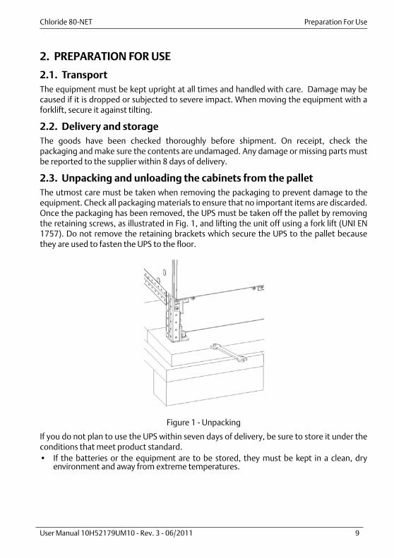
2.3. Unpacking and unloading the cabinets from the palletThe utmost care must be taken when removing the packaging to prevent damage to theequipment. Check all packaging materials to ensure that no important items are discarded.Once the packaging has been removed, the UPS must be taken off the pallet by removingthe retaining screws, as illustrated in Fig. 1, and lifting the unit off using a fork lift (UNI EN1757). Do not remove the retaining brackets which secure the UPS to the pallet becausethey are used to fasten the UPS to the floor.
Figure 1 - Unpacking
If you do not plan to use the UPS within seven days of delivery, be sure to store it under theconditions that meet product standard.• If the batteries or the equipment are to be stored, they must be kept in a clean, dry
environment and away from extreme temperatures.

Preparation For Use Chloride 80-NET
10 User Manual 10H52179UM10 - Rev. 3 - 06/2011
2.4. Environmental conditionsThe UPS must be installed vertically, on a level and even surface, and in an area protectedfrom extremes of temperature, water and humidity. Do not stack the units or place objectson top of them.The operating temperature range of the UPS is 0°C - 40°C.The ideal environmental temperature range is 15 °C to 25 °C. The battery life is specified for20°C. Each increment of 10 °C above 25 °C reduces the expected life by 50%.
2.4.1. Installation altitude
The maximum operating altitude of the UPS, without derating, is 1000 m. At higher altitudesthe load must be reduced according to Fig. 2.
Figure 2 - Permissible load dependent on installation altitude
Load
in %
Installation altitude in m

Chloride 80-NET Preparation For Use
User Manual 10H52179UM10 - Rev. 3 - 06/2011 11
2.5. Access to service area and cooling systemWhen installed, the UPS can only be accessed from the front. All front doors have amaximum aperture of 90°. The area must have sufficient space for installation procedures tobe carried out. Access doors must be wide enough to permit unobstructed transport of thedevice (chap. 2. on page 9). To allow correct air flow for the cooling system, leave aminimum distance of 500 mm between the top of the cabinet and the ceiling of theinstallation area. The UPS air intake is at the front, and the air outlet is on the top (see Fig. 3).
Figure 3 - In/out air flow
AIR FLOW OUTLET
AIR FLOWINTAKE
Preparation For Use Chloride 80-NET
12 User Manual 10H52179UM10 - Rev. 3 - 06/2011
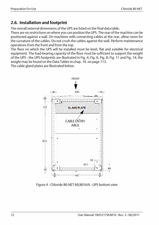
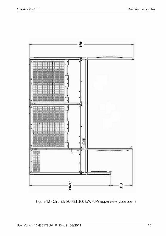
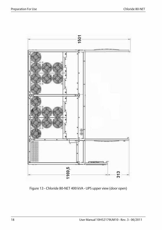
2.6. Installation and footprintThe overall external dimensions of the UPS are listed on the final data table.There are no restrictions on where you can position the UPS. The rear of the machine can bepositioned against a wall. On machines with connecting cables at the rear, allow room forthe curvature of the cables. Do not crush the cables against the wall. Perform maintenanceoperations from the front and from the top.The floor on which the UPS will be installed must be level, flat and suitable for electricalequipment. The load-bearing capacity of the floor must be sufficient to support the weightof the UPS - the UPS footprints are illustrated in Fig. 4, Fig. 6, Fig. 8, Fig. 11 and Fig. 14, theweight may be found on the Data Tables in chap. 10. on page 113.The cable gland plates are illustrated below:
Figure 4 - Chloride 80-NET 60/80 kVA - UPS bottom view
CABLE ENTRY AREA
FRONT
Chloride 80-NET Preparation For Use
User Manual 10H52179UM10 - Rev. 3 - 06/2011 13
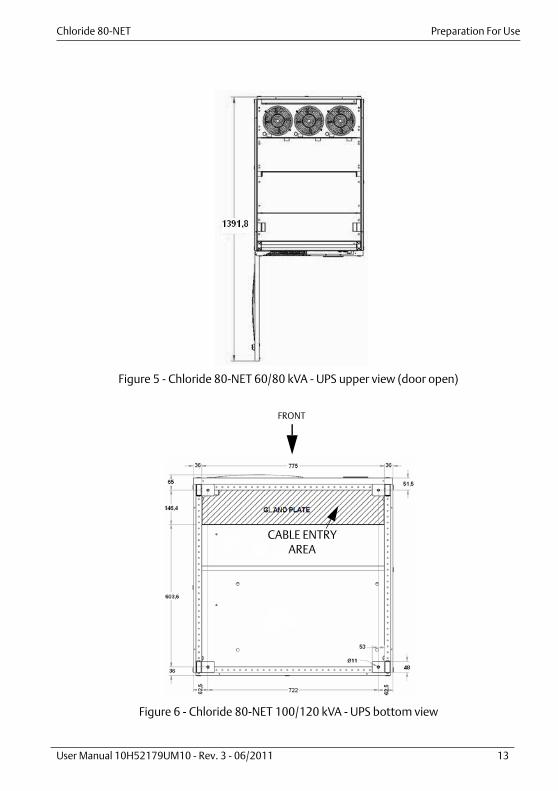
Figure 5 - Chloride 80-NET 60/80 kVA - UPS upper view (door open)
Figure 6 - Chloride 80-NET 100/120 kVA - UPS bottom view
FRONT
CABLE ENTRY AREA

Preparation For Use Chloride 80-NET
14 User Manual 10H52179UM10 - Rev. 3 - 06/2011
Figure 7 - Chloride 80-NET 100/120 kVA - UPS upper view (door open)
Figure 8 - Chloride 80-NET 160/200 kVA - UPS bottom view(position and dimensions of the feet and cable entry area)
FRONT
CABLE ENTRY AREA
GLANDPLATE
Chloride 80-NET Preparation For Use
User Manual 10H52179UM10 - Rev. 3 - 06/2011 15
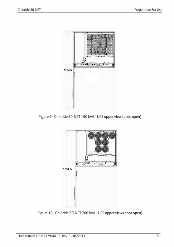
Figure 9 - Chloride 80-NET 160 kVA - UPS upper view (door open)
Figure 10 - Chloride 80-NET 200 kVA - UPS upper view (door open)

Preparation For Use Chloride 80-NET
16 User Manual 10H52179UM10 - Rev. 3 - 06/2011
Figure 11 - Chloride 80-NET 300/400 kVA - UPS bottom view(position and dimensions of the feet and cable entry area)
FRO
NT
CA
BLE
ENTR
Y A
REA
GLA
ND
PLA
TE
Chloride 80-NET Preparation For Use
User Manual 10H52179UM10 - Rev. 3 - 06/2011 17
Figure 12 - Chloride 80-NET 300 kVA - UPS upper view (door open)
Preparation For Use Chloride 80-NET
18 User Manual 10H52179UM10 - Rev. 3 - 06/2011
Figure 13 - Chloride 80-NET 400 kVA - UPS upper view (door open)

Chloride 80-NET Preparation For Use
User Manual 10H52179UM10 - Rev. 3 - 06/2011 19
Figure 14 - Chloride 80-NET 500 kVA - UPS bottom view(position and dimensions of the feet and cable entry area)
FRO
NT
CA
BLE
ENTR
Y A
REA
GLA
ND
PLA
TE

Preparation For Use Chloride 80-NET
20 User Manual 10H52179UM10 - Rev. 3 - 06/2011
Figure 15 - Chloride 80-NET 500 kVA - UPS upper view (door open)

Chloride 80-NET Installation
User Manual 10H52179UM10 - Rev. 3 - 06/2011 21
3. INSTALLATION
3.1. Electrical preparations
WarningFor reasons of safety, the secondary access panel MUST NOT BE REMOVED. If, for any reason, it is necessary to remove this panel, the entire installation must be switched off and de-energized; otherwise complete safety cannot be guaranteed. The UPS is connected to 400/230 V three-phase power lines; DC voltagesabove 500 V are also found in the battery circuit. Installation must only becarried out by qualified personnel in accordance with these operatinginstructions and both national and local electrical codes. Since UPS devicescreate a large leakage current, connect the device to ground prior toplacement into service. Improper connection can damage the device andlead to injuries and even death.
WarningWith regard to electromagnetic conformance, the device was developed inaccordance with product standard IEC/EN 62040-2. The UPS must beprotected against overvoltages in line power in excess of those at which it wastested. Over voltages in the power supply system may occur for severalreasons, including lightning strikes, ON/OFF switching of inductive orcapacitive loads (such as power transformers or capacitor banks), and short-circuit shutdowns.
NoticeQS1, QS2 and QS4 are used for disconnecting.
WarningDo not operate the battery switch QS9 when the inverter is ON.

Installation Chloride 80-NET
22 User Manual 10H52179UM10 - Rev. 3 - 06/2011
3.2. Currents and suggested cable sizesFor external wiring requirements, see Table 1 on page 29 and Table 3 on page 30. Seenational and local rules for selection of conductor size. Connect the line power cables to UPSterminals U, V, W, N. Connect the bypass line power cables to UPS terminals U1, V1, W1, N.Connect the load to UPS terminals U2, V2, W2, N. (see Fig. 20 on page 31).In the absence of a separate Bypass line power supply, connect jumpers between U and U1,V and V1, W and W1.The cross section indicated in Table 1 on page 29 and Table 3 on page 30 refer to thefollowing conditions:1) 70°C rated PVC copper cables;2) Cable routed in conduits for electrical installations. Separated conduits for each line;3) Air temperature in the conduits not exceeding 30°C;4) Cable lengths up to 30 m;5) Stranded wires up to 35 mm2 and for single wires above 35 mm2.
NoticeFor different conditions, it will be necessary to verify whether cabledimensions meet the requirements of IEC 60287.
NoticeWhen selecting the cable, it is important to take into account the voltagedrop due to the cable length (if the voltage drop exceeds 3%, increase thecross section).
NoticeIf the UPS supplies predominantly non-linear loads, the cross section of thePEN conductor must be oversized by a factor of 1.7 for 60-200 kVA or 1.5 for300-500 kVA.
NoticeTo avoid electrical interference:• - power cables (primary input, bypass input, battery, output load cables)
should be routed separately• - communication and data lines should be routed using proper conduits
and kept separate from all power cables.
NoticeThe cross section of the ground cables indicated in Table 1 on page 29 and Table 3 on page 30 is indicative. It must be selected in accordance with national and local rules, and coordinated with protection devices installed ahead of the UPS.

Chloride 80-NET Installation
User Manual 10H52179UM10 - Rev. 3 - 06/2011 23
3.3. Physical appearanceLegend:• QS1 = LINE POWER INPUT SWITCH• QS2 = BYPASS LINE POWER SWITCH• QS3 = MAINTENANCE BYPASS SWITCH• QS4 = OUTPUT SWITCH• QS9 = BATTERY SWITCH
Figure 16 - Chloride 80-NET 60/80/100/120 kVA - UPS front view
Connectivity panel
QS1 QS2 QS4QS3 QS9
QS1 QS2 QS4
QS3 QS9
60/80kVA 100/120 KVA
ST. SW./BOOST MODULEST. SW./BOOST MODULE
INVERTER MODULEINVERTER MODULE
RECTIFIER MODULERECTIFIER MODULE

Installation Chloride 80-NET
24 User Manual 10H52179UM10 - Rev. 3 - 06/2011
Figure 17 - Chloride 80-NET 160/200 kVA - UPS front view
QS1
QS2
QS4
QS3
QS9
INVERTER MODULEPHASE U
RECTIFIER MODULEPHASE V
INVERTER MODULEPHASE W
BOOST MODULE
RECTIFIER MODULEPHASE U
INVERTER MODULEPHASE V
RECTIFIER MODULEPHASE W
STATIC SWITCHMODULE
QS4
Connectivity panel

Chloride 80-NET Installation
User Manual 10H52179UM10 - Rev. 3 - 06/2011 25
Figure 18 - Chloride 80-NET 300/400 kVA - UPS front view
MO
DU
LE
REC
TIFI
ER 2
PHA
SE U
MO
DU
LE
INV
ERTE
R 2
PHA
SE U
MO
DU
LE
INV
ERTE
R 2
PHA
SE V
MO
DU
LE
REC
TIFI
ER 2
PHA
SE V
MO
DU
LE
REC
TIFI
ER 2
PHA
SE W
MO
DU
LE
INV
ERTE
R 2
PHA
SE W
MO
DU
LEBO
OST
1
MO
DU
LEBO
OST
2
MO
DU
LE
REC
TIFI
ER 1
PHA
SE U
MO
DU
LE
INV
ERTE
R 1
PHA
SE U
MO
DU
LEPH
ASE
V
MO
DU
LE
REC
TIFI
ER 1
PHA
SE V
MO
DU
LE
REC
TIFI
ER 1
PHA
SE W
MO
DU
LE
INV
ERTE
R 1
PHA
SE W
MO
DU
LEST
ATI
C
INV
ERTE
R 1
QS1
QS2
QS3 QS4
QS9
Con
nect
ivit
y pa
nel

Installation Chloride 80-NET
26 User Manual 10H52179UM10 - Rev. 3 - 06/2011
Figure 19 - Chloride 80-NET 500 kVA - UPS front view
MO
DU
LERE
CTI
FIER
1
PHA
SE V
MO
DU
LERE
CTI
FIER
2
PHA
SE V
MO
DU
LERE
CTI
FIER
1
PHA
SE W
MO
DU
LERE
CTI
FIER
2
PHA
SE W
MO
DU
LEIN
VER
TER
1
PHA
SE V
MO
DU
LEIN
VER
TER
2
PHA
SE V
MO
DU
LEBO
OST
3
MO
DU
LEBO
OST
4
Con
nect
ivit
y pa
nel
QS1
QS2
QS3
QS4
QS9
MO
DU
LERE
CTI
FIER
1
PHA
SE U
MO
DU
LEBO
OST
1
MO
DU
LERE
CTI
FIER
2
PHA
SE U
MO
DU
LEIN
VER
TER
1
PHA
SE U
MO
DU
LEIN
VER
TER
2
PHA
SE U
MO
DU
LEIN
VER
TER
1
PHA
SE W
MO
DU
LEIN
VER
TER
2
PHA
SE W
MO
DU
LEBO
OST
2
MO
DU
LEST
ATI
C

Chloride 80-NET Installation
User Manual 10H52179UM10 - Rev. 3 - 06/2011 27
3.4. External protection devicesThis device is equipped with manual switches intended only for Service Bypass and InternalService operations. It is therefore essential that the customer install external protectiondevices at the installation site. These must be installed near the unit and labelled as the linepower separation device for the UPS (see IEC/EN 62040-1).
3.4.1. Use of differential protection devices
A differential device installed on the primary and bypass inputs supply senses the sum of allground leakage currents in both the UPS and the load it supplies.To avoid spurious operation, the following must be taken into consideration when selectingdifferential protection devices for installation on input lines:
1 The nominal value of ID must take into account the ground leakage current of the UPSand the load under normal operating conditions: ID = IDUPS + load leakage current. N.B. The maximum limit for UPS ground leakage current is 5% of nominal input current(see IEC/EN62040-1)
2 Be of a delayed operation type (greater than 30 0mS);3 The type of differential switch used must conform to product regulation
IEC/EN62040-1.
WarningThe following label must be displayed on all switching devices installed in the sameelectrical system as the UPS, even when they are located far from the area where thesystem is located (according to European standard IEC/EN 62040-1):
MAKE SURE THE UNINTERRUPTIBLE POWER SYSTEM IS ISOLATEDBEFORE WORKING ON THIS CIRCUIT
Notice - Differential Current Breakers• The UPS does not require differential protection devices connected ahead of it.
However, when these devices are installed in compliance with localregulations, note that separate DCBs in the line power and bypass line powercircuits may trip unexpectedly, thus interrupting the power supply to the unit.Therefore, if a DCB must be installed, only one should be used for both primaryand bypass inputs.
• In parallel distributed systems, only one common differential protection deviceshould be installed ahead of the point where the line divides into the UPSprimary and bypass line power circuits. If separate DCBs are installed indifferent configurations, they may trip unexpectedly.
• In order to guarantee correct distribution in the neutral cables, installationpersonnel shall make sure that the lengths of the cables are as equal aspossible.However, if the bypass lines lead from sources that are electrically isolatedfrom each other, a differential protection device may be installed on each line.In this case, and in cases when the load is supplied from the Bypass via theStatic Bypass Switch, the isolated sources are connected in parallel. A case-by-case analysis should be made as to whether any resulting imbalance betweenthe currents on the Bypass lines is compatible with the respective protectiondevices.
Installation Chloride 80-NET
28 User Manual 10H52179UM10 - Rev. 3 - 06/2011
3.4.2. Primary line power input
These should be capable of protecting the primary AC line power ahead of the UPS. It shouldbe able to handle the maximum input current of the UPS (Table 1 on page 29 and Table 3 onpage 30) and to interrupt the circuit at its maximum current level during a short circuit.
3.4.3. Bypass line power input
Bypass line power input protection devices must have the following characteristics:
1 Maximum current rated in accordance with the values in Table 1 on page 29 and Table 3on page 30;
2 I2t rating lower than the thyristor rating (see chap. 10. on page 113 for pre-arc I2tratings) in order to protect it in case of output short circuit. To allow for componenttolerances, the external protection device pre-arc I2t rating should not exceed 80% ofthe thyristor I2t rating;
3 Pre-arc I2t rating higher than that of the Inverter fuse (already installed inside the UPS -see chap. 10. on page 113 for pre-arc I2t ratings) so that the Inverter fuse will blow incase of an overcurrent caused by an internal failure. In this case the load is supplied bythe Bypass - to allow for component tolerances, the external protection device pre-arcI2t rating should be at least 20% higher than that of the Inverter fuse.
3.4.4. Battery input
These should be capable of protecting the battery against short-circuits, and should takeinto account the maximum current drain (during discharge at 1.8V per cell), see Table 1 onpage 29 and Table 3 on page 30. These devices should be installed as close as possible to thebattery.
3.4.5. UPS Output line
Since load(s) can be supplied through the Uninterruptible Power System from two sources,the ratings of the following supplies should be taken into account when designing theoutput line protection system.Supply from inverter:see Table 1 on page 29 and Table 3 on page 30 and chap. 10. on page 113Supply from Static Bypass Switch and maintenance Static Bypass Switch:see Table 1 on page 29 and Table 3 on page 30 and chap. 10. on page 113
N.B. If a single differential breaker is installed ahead of the UPS, any fault in the installationgrounding system will result in the interruption of power to both the line power input andthe direct line.
Chloride 80-NET Installation
User Manual 10H52179UM10 - Rev. 3 - 06/2011 29
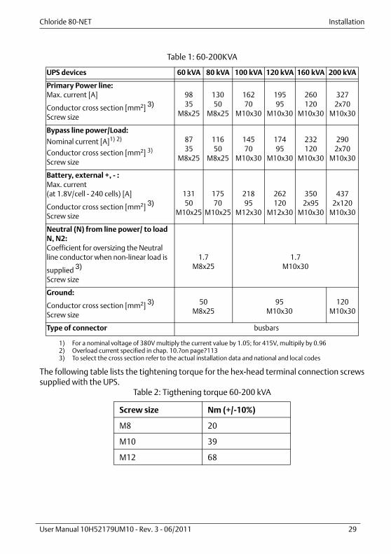
Table 1: 60-200KVA
The following table lists the tightening torque for the hex-head terminal connection screwssupplied with the UPS.
Table 2: Tigthening torque 60-200 kVA
UPS devices 60 kVA 80 kVA 100 kVA 120 kVA 160 kVA 200 kVA
Primary Power line:Max. current [A]
Conductor cross section [mm2] 3)
Screw size
9835
M8x25
13050
M8x25
16270
M10x30
19595
M10x30
260120
M10x30
3272x70
M10x30
Bypass line power/Load:
Nominal current [A]1) 2)
Conductor cross section [mm2] 3)
Screw size
1) For a nominal voltage of 380V multiply the current value by 1.05; for 415V, multipily by 0.962) Overload current specified in chap. 10.?on page?1133) To select the cross section refer to the actual installation data and national and local codes
8735
M8x25
11650
M8x25
14570
M10x30
17495
M10x30
232120
M10x30
2902x70
M10x30
Battery, external +, - :Max. current(at 1.8V/cell - 240 cells) [A]
Conductor cross section [mm2] 3)
Screw size
13150
M10x25
17570
M10x25
21895
M12x30
262120
M12x30
3502x95
M10x30
4372x120
M10x30
Neutral (N) from line power/ to load N, N2:Coefficient for oversizing the Neutral line conductor when non-linear load is
supplied 3)
Screw size
1.7M8x25
1.7M10x30
Ground:
Conductor cross section [mm2] 3)
Screw size
50M8x25
95M10x30
120M10x30
Type of connector busbars
Screw size Nm (+/-10%)
M8 20
M10 39
M12 68
Installation Chloride 80-NET
30 User Manual 10H52179UM10 - Rev. 3 - 06/2011
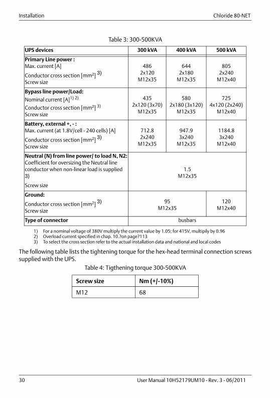
Table 3: 300-500KVA
The following table lists the tightening torque for the hex-head terminal connection screwssupplied with the UPS.
Table 4: Tigthening torque 300-500KVA
UPS devices 300 kVA 400 kVA 500 kVA
Primary Line power :Max. current [A]
Conductor cross section [mm2] 3)
Screw size
4862x120
M12x35
6442x180
M12x35
8052x240
M12x40
Bypass line power/Load:
Nominal current [A]1) 2)
Conductor cross section [mm2] 3)
Screw size
1) For a nominal voltage of 380V multiply the current value by 1.05; for 415V, multipily by 0.962) Overload current specified in chap. 10.?on page?1133) To select the cross section refer to the actual installation data and national and local codes
4352x120 (3x70)
M12x35
5802x180 (3x120)
M12x35
7254x120 (2x240)
M12x40
Battery, external +, - :Max. current (at 1.8V/cell - 240 cells) [A]
Conductor cross section [mm2] 3)
Screw size
712.82x240
M12x35
947.93x240
M12x35
1184.83x240
M12x40
Neutral (N) from line power/ to load N, N2:Coefficient for oversizing the Neutral line conductor when non-linear load is supplied 3)
Screw size
1.5M12x35
Ground:
Conductor cross section [mm2] 3)
Screw size
95M12x35
120M12x40
Type of connector busbars
Screw size Nm (+/-10%)
M12 68

Chloride 80-NET Installation
User Manual 10H52179UM10 - Rev. 3 - 06/2011 31
3.5. Backfeed protectionTo prevent electric shock hazards caused by backfeed through the the Static Bypass Switch,an external disconnector must be installed in conformance with Product Standard IEC/EN62040-1. The UPS generates a logic command at XT2 (see Fig. 29, Fig. 30, Fig. 31, Fig. 32 andFig. 33) to ensure that the disconnector operates correctly.
N.B. In case of single-line feeder, the disconnector must be installed ahead of the UPSprimary and bypass inputs. When this disconnector is activated, the UPS switches to BatteryMode.
N.B. The PE and N terminals must be connected in accordance with the requirements ofthe local line power distribution system (TN-C, TN-S, TN-C-S, TT etc.). For instance, inTN-C installations the PEN conductor from the supply transformer must be connected to theUPS PE and N terminals. See para. 3.6 on page 32 and Fig. 43 on page 103.
Figure 20 - External protection devices
Line Power Supply Bypass Line Power Supply

Installation Chloride 80-NET
32 User Manual 10H52179UM10 - Rev. 3 - 06/2011
3.6. External electrical connectionsTo access the external electrical connections, open the front door of the UPS and remove thesecondary access panel (see Fig. 16, Fig. 17, Fig. 18 and Fig. 19). Connect the ground cable(PE) first at .
Make sure the UPS is isolated before removing panels.
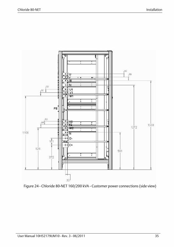
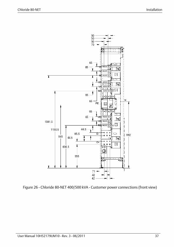
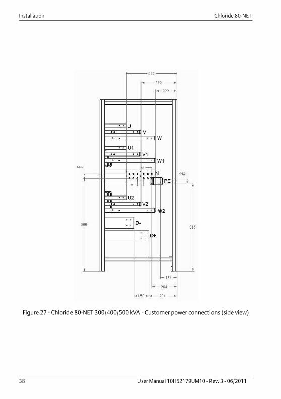
3.7. Power connectionsThe power connections (see Fig. 21-Fig. 27) on the front of the UPS are: • U, V, W - LINE POWER INPUT• U1, V1, W1 - LINE POWER BYPASS (only at the standard UPS type)• N - NEUTRAL BAR (PEN/N) (COMMON TEST POINT FOR PRIMARY INPUT NEUTRAL,
BYPASS INPUT NEUTRAL AND OUTPUT NEUTRAL)• U2, V2, W2 - UPS OUTPUT TO LOAD• D-, C+ - BATTERY TERMINALS
• GROUND CONNECTION (PE)
NoticeFor a TN-C distribution system, connect an insulated jumper between UPSground and the UPS Neutral connector. Refer to local Standards and regulations for the correct jumper cross section.Connect line power cable PEN to the UPS Neutral connector (N).
NoticeEnsure that the line power and load conductors are connected to the UPS as aclockwise (right hand) 3 phase system.

Chloride 80-NET Installation
User Manual 10H52179UM10 - Rev. 3 - 06/2011 33
Figure 21 - Chloride 80-NET 60/80 kVA - Customer power connections (front view)
Figure 22 - Chloride 80-NET 100/120 kVA - Customer power connections (front view)
The distance between the power connection holes is 36 mm, unless otherwise specified.
The distance between the power connection holes is 50 mm, unless otherwise specified.

Installation Chloride 80-NET
34 User Manual 10H52179UM10 - Rev. 3 - 06/2011
Figure 23 - Chloride 80-NET 160/200 kVA - Customer power connections (front view)
Chloride 80-NET Installation
User Manual 10H52179UM10 - Rev. 3 - 06/2011 35
Figure 24 - Chloride 80-NET 160/200 kVA - Customer power connections (side view)

Installation Chloride 80-NET
36 User Manual 10H52179UM10 - Rev. 3 - 06/2011
Figure 25 - Chloride 80-NET 300 kVA - Customer power connections (front view)
Chloride 80-NET Installation
User Manual 10H52179UM10 - Rev. 3 - 06/2011 37
Figure 26 - Chloride 80-NET 400/500 kVA - Customer power connections (front view)
Installation Chloride 80-NET
38 User Manual 10H52179UM10 - Rev. 3 - 06/2011
Figure 27 - Chloride 80-NET 300/400/500 kVA - Customer power connections (side view)

Chloride 80-NET Installation
User Manual 10H52179UM10 - Rev. 3 - 06/2011 39
3.8. Connecting the batteriesThe UPS is equipped with a separating device for the battery DC power connection.
Before connecting the batteries, please read the notice and warning label on the UPS or battery compartment.
NoticeFull safety instructions on the use and maintenance of UPS batteries areprovided in the appropriate battery manufacturers' manuals. The batterysafety information contained in this section consists of key considerationswhich must be taken into account when designing the installation and mayaffect its outcome, depending on local conditions.
WarningSpecial care should be taken when working with the batteries associated withthe Chloride 80-NET. When all batteries are connected together the overallvoltage exceeds 500V. It is very important to make sure that the batteries are separately installed in aspecially designed, lockable, dedicated battery cabinet or battery room.Battery cabinet specifications can be found in para 9.5. on page 105 of thismanual.
WarningIn the event of malfunction, the battery shelves and/or cabinet or batteryholders may become live!
NoticeThe requirements of EC directives are met when battery compartments withoriginal accessories are used. If other batteries are used, make sure that theapplicable EC directives are met and that conformance is declared. The UPSmust still be parameterized with the service software and equipped with an all-pole disconnecting device and fuses, as per Table 1 on page 29 and Table 3 onpage 30. When dimensioning your battery cables, note the connectiontolerances at terminals +/-.
WarningENSURE CORRECT POLARITY!

Installation Chloride 80-NET
40 User Manual 10H52179UM10 - Rev. 3 - 06/2011
NoticeThe most common battery type used in UPS installations is the valveregulated battery. Valve regulated cells are not sealed. The amount of gas given off is less than for flooded cells, but when planningthe battery installation, allowance must be made for adequate ventilationand heat dissipation. Valve-regulated cells are not completely maintenance-free. They must bekept clean and their connections checked periodically to ensure they aretight and that there is no evidence of corrosion. It is inevitable that batteries will lose some charge during transportation andstorage. Before attempting a capacity test, make sure the batteries are fullycharged, as this may take several hours. Cell performance typically improves after a few discharge/recharge cycles.
NoticeThe battery charger can be configured for different types of batteries anddifferent numbers of cells. In the technical data table (chap. 10. on page 113)lists the type of batteries that can be used and the number of the cells for whichthe battery charger is configured. The maximum charging current is selectableand depends on the rating of the UPS and its operating conditions (chap. 10. onpage 113). Several charging methods (depending on the type of battery) areavailable and can be configured by authorized personal only.

Chloride 80-NET Installation
User Manual 10H52179UM10 - Rev. 3 - 06/2011 41
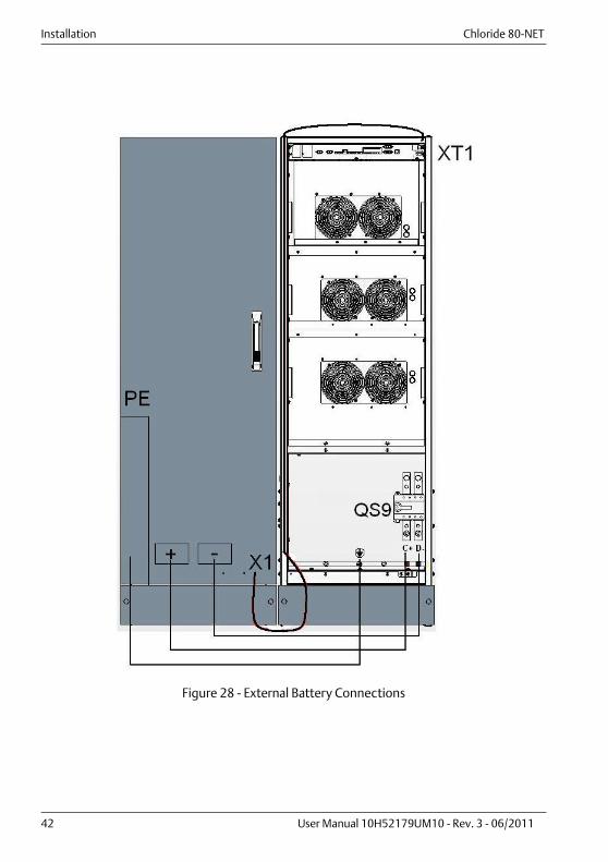
3.9. Connections between battery compartments and UPSThe cables for connecting the UPS to the battery cabinets are not supplied. They can beprovided by the manufacturer upon special request.A battery area temperature sensor is supplied as standard equipment and includes aconnecting cable with length of 7 meters.
• The battery area temperature sensor should be installed adjacent to the UPS (see Fig.21-Fig. 27 for the position of the input battery connections inside the UPS).
• Make the ground connections (PE).• Connect the batteries with cables, as suggested in Table 1 on page 29 and Table 3 on
page 30 to terminals + (positive pole) and - (negative pole), and in accordance with theconnection diagram.
• Connect the battery area temperature sensor to connector XT1 in the connectivitypanel (Fig. 29, Fig. 30, Fig. 31, Fig. 32, Fig. 33).
• The wires that connect the temperature probe must be shielded and routed indedicated conduits that are separate from the power cables.
• Connect the two wires (if installed) that monitor the status of the external batterydisconnector to XT1/2 in the connectivity panel (Fig. 29, Fig. 30, Fig. 31, Fig. 32, Fig.33). These wires must be routed in a dedicated conduit that is separate from the powercables. To improve noise immunity, use twisted pairs or shielded wires.
WarningBefore the system starts, ensure that UPS battery connection polarity is correct.Wrong connections can damage the system and endanger operator safety.
Installation Chloride 80-NET
42 User Manual 10H52179UM10 - Rev. 3 - 06/2011
Figure 28 - External Battery Connections

Chloride 80-NET Installation
User Manual 10H52179UM10 - Rev. 3 - 06/2011 43
3.10. Handling the batteries
3.10.1. Recharging batteries
3.10.2. Replacing batteries
3.10.3. Connecting external batteries
WarningBatteries are a potential source of danger due to their electrical charge andchemical composition. Therefore, observe the handling instructions providedby the battery manufacturer. These usually can be found in the material whichis included in the shipment.
NoticeWhen recharging, follow the instructions printed on the packaging
NoticeBefore replacing batteries, make sure the new batteries are fully charged.
WarningIf a battery has been disconnected and must be reconnected, the batteryisolator may be reconnected only after you have made certain that voltagewith the correct polarity is present in the intermediate circuit (see Connectingthe Batteries).

Installation Chloride 80-NET
44 User Manual 10H52179UM10 - Rev. 3 - 06/2011

Chloride 80-NET CONNECTIVITY PANEL
User Manual 10H52179UM10 - Rev. 3 - 06/2011 45
4. CONNECTIVITY PANEL
Chloride 80-NET is equipped with the following interfaces:• XS3) Slot for Connectivity Products (X3 will be switched to XS3 to parameterize
Connectivity Products);• XS6) Slot for LIFE.net modem;• X3) Serial Interface for Service;• X6) Serial Interface for external LIFE.net;• XT1/2) 4-pole screw connector. Pin 1 and 2 to monitor the external battery
disconnector;• X9) RJ-45 Ethernet Interface for Service and Placement into service only;• XT3/8) 4-pole screw connector for RPO Input and Output;• XT4) not used;• TB1) 2x16-pole screw connector for input and output contacts;• X19A/B) 2x15-pole connectors for parallel UPS connection;• X20) RJ-45 Interface for synchronization with external signal;• XT1) 2-pole Battery Area Temperature sensor (input);• XT2) 2-pole screw connector for Backfeed output contact;.
Figure 29 - Chloride 80-NET 60/80 kVA - Connectivity panel
Figure 30 - Chloride 80-NET 100/120 kVA - Connectivity panel
Figure 31 - Chloride 80-NET 160/200 kVA - Connectivity panel
XS3 XS6RS232-1
X3 XT1/2X9
XT3/8
XT4
TB1
X19/A
X19/B
X20 XT1
XT2RS232-2
X6
XS3 XS6
RS232-1X3
XT1/2
X9
XT3/8
XT4
TB1
X19/A
X19/B
X20 XT1XT2RS232-2X6
XS3 XS6
RS232-1X3
XT1/2
X9
XT3/8
XT4
TB1
X19/A
X19/B
X20XT1
XT2
RS232-2X6
CONNECTIVITY PANEL Chloride 80-NET
46 User Manual 10H52179UM10 - Rev. 3 - 06/2011
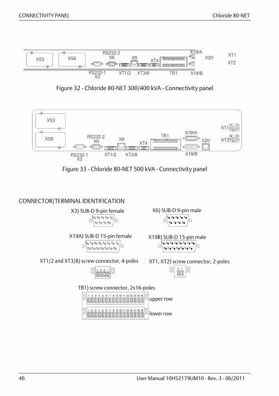
Figure 32 - Chloride 80-NET 300/400 kVA - Connectivity panel
Figure 33 - Chloride 80-NET 500 kVA - Connectivity panel
CONNECTOR/TERMINAL IDENTIFICATION
XS3 XS6
RS232-1X3
XT1/2
X9
XT3/8
XT4
TB1
X19/A
X19/B
X20 XT1
XT2
RS232-2X6
XS3
XS6
RS232-1X3
RS232-2X6
XT1/2
X9
XT3/8
XT4
TB1X19/A
X19/B
X20
XT1
XT2
X3) SUB-D 9-pin female
X19A) SUB-D 15-pin female
X6) SUB-D 9-pin male
X19B) SUB-D 15-pin male
XT1, XT2) screw connector, 2-poles
TB1) screw connector, 2x16-poles
upper row
lower row
XT1/2 and XT3/8) screw connector, 4-poles
Chloride 80-NET CONNECTIVITY PANEL
User Manual 10H52179UM10 - Rev. 3 - 06/2011 47
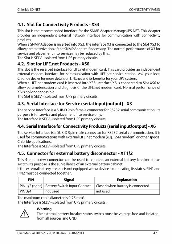
4.1. Slot for Connectivity Products - XS3This slot is the recommended interface for the SNMP Adapter ManageUPS NET. This Adapterprovides an independent external network interface for communication with connectivityproducts.When a SNMP Adapter is inserted into XS3, the interface X3 is connected to the Slot XS3 toallow parameterization of the SNMP Adapter if necessary. The normal performance of X3 forservice and placement into service may be reduced by this.The Slot is SELV - isolated from UPS primary circuits.
4.2. Slot for LIFE.net Products - XS6This slot is the reserved interface for LIFE.net modem card. This card provides an independentexternal modem interface for communication with LIFE.net service station. Ask your localChloride dealer for more details on LIFE.net and its benefits for your UPS system.When a LIFE.net modem card is inserted into XS6, interface X6 is connected to Slot XS6 toallow parameterisation and diagnosis of the LIFE.net modem card. Normal performance ofX6 is no longer possible.The Slot is SELV - isolated from UPS primary circuits.
4.3. Serial Interface for Service (serial input/output) - X3The service Interface is a SUB-D 9pin female connector for RS232 serial communication. Itspurpose is for service and placement into service only.The Interface is SELV - isolated from UPS primary circuits.
4.4. Serial Interface for Connectivity Products (serial input/output) - X6The service Interface is a SUB-D 9pin male connector for RS232 serial communication. It isused for communications with external LIFE.net modem (e.g. GSM modem) or other specialChloride applications.The Interface is SELV - isolated from UPS primary circuits.
4.5. Connector for external battery disconnector - XT1/2This 4-pole screw connector can be used to connect an external battery breaker statusswitch. Its purpose is the surveillance of an external battery cabinet.If the external battery breaker is not equipped with a device for indicating its status, PIN1 andPIN2 must be connected together.
The maximum cable diameter is 0.75 mm2.The Interface is SELV - isolated from UPS primary circuits.
PIN Signal Explanation
PIN 1/2 (right) Battery Switch Input Contact Closed when battery is connectedPIN 3/4 not used not used
WarningThe external battery breaker status switch must be voltage-free and isolatedfrom all sources and GND.
CONNECTIVITY PANEL Chloride 80-NET
48 User Manual 10H52179UM10 - Rev. 3 - 06/2011
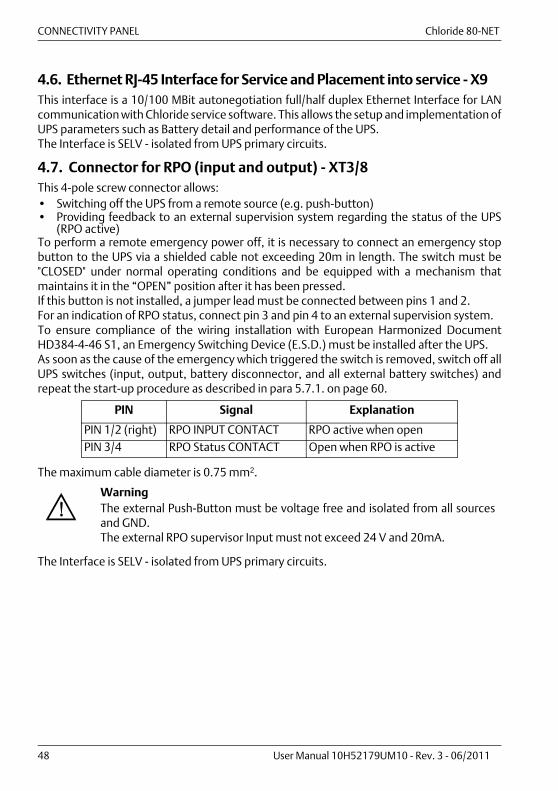
4.6. Ethernet RJ-45 Interface for Service and Placement into service - X9This interface is a 10/100 MBit autonegotiation full/half duplex Ethernet Interface for LANcommunication with Chloride service software. This allows the setup and implementation ofUPS parameters such as Battery detail and performance of the UPS.The Interface is SELV - isolated from UPS primary circuits.
4.7. Connector for RPO (input and output) - XT3/8This 4-pole screw connector allows:• Switching off the UPS from a remote source (e.g. push-button)• Providing feedback to an external supervision system regarding the status of the UPS
(RPO active)To perform a remote emergency power off, it is necessary to connect an emergency stopbutton to the UPS via a shielded cable not exceeding 20m in length. The switch must be"CLOSED" under normal operating conditions and be equipped with a mechanism thatmaintains it in the “OPEN” position after it has been pressed.If this button is not installed, a jumper lead must be connected between pins 1 and 2.For an indication of RPO status, connect pin 3 and pin 4 to an external supervision system.To ensure compliance of the wiring installation with European Harmonized DocumentHD384-4-46 S1, an Emergency Switching Device (E.S.D.) must be installed after the UPS.As soon as the cause of the emergency which triggered the switch is removed, switch off allUPS switches (input, output, battery disconnector, and all external battery switches) andrepeat the start-up procedure as described in para 5.7.1. on page 60.
The maximum cable diameter is 0.75 mm2.
The Interface is SELV - isolated from UPS primary circuits.
PIN Signal Explanation
PIN 1/2 (right) RPO INPUT CONTACT RPO active when openPIN 3/4 RPO Status CONTACT Open when RPO is active
WarningThe external Push-Button must be voltage free and isolated from all sourcesand GND.The external RPO supervisor Input must not exceed 24 V and 20mA.
Chloride 80-NET CONNECTIVITY PANEL
User Manual 10H52179UM10 - Rev. 3 - 06/2011 49
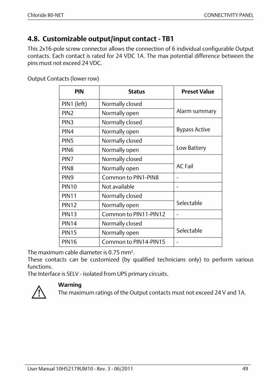
4.8. Customizable output/input contact - TB1This 2x16-pole screw connector allows the connection of 6 individual configurable Outputcontacts. Each contact is rated for 24 VDC 1A. The max potential difference between thepins must not exceed 24 VDC.
Output Contacts (lower row)
The maximum cable diameter is 0.75 mm2.These contacts can be customized (by qualified technicians only) to perform variousfunctions.The Interface is SELV - isolated from UPS primary circuits.
PIN Status Preset Value
PIN1 (left) Normally closedAlarm summaryPIN2 Normally open
PIN3 Normally closedBypass ActivePIN4 Normally open
PIN5 Normally closedLow BatteryPIN6 Normally open
PIN7 Normally closedAC FailPIN8 Normally open
PIN9 Common to PIN1-PIN8 -
PIN10 Not available -
PIN11 Normally closedSelectablePIN12 Normally open
PIN13 Common to PIN11-PIN12 -
PIN14 Normally closedSelectablePIN15 Normally open
PIN16 Common to PIN14-PIN15 -
WarningThe maximum ratings of the Output contacts must not exceed 24 V and 1A.
CONNECTIVITY PANEL Chloride 80-NET
50 User Manual 10H52179UM10 - Rev. 3 - 06/2011
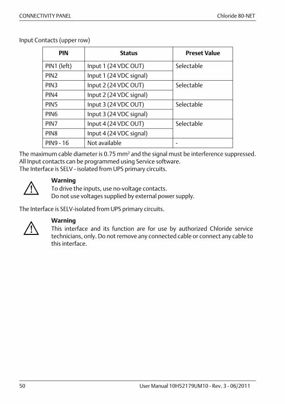
Input Contacts (upper row)
The maximum cable diameter is 0.75 mm2 and the signal must be interference suppressed.All Input contacts can be programmed using Service software.The Interface is SELV - isolated from UPS primary circuits.
The Interface is SELV-isolated from UPS primary circuits.
PIN Status Preset Value
PIN1 (left) Input 1 (24 VDC OUT) Selectable
PIN2 Input 1 (24 VDC signal)
PIN3 Input 2 (24 VDC OUT) Selectable
PIN4 Input 2 (24 VDC signal)
PIN5 Input 3 (24 VDC OUT) Selectable
PIN6 Input 3 (24 VDC signal)
PIN7 Input 4 (24 VDC OUT) Selectable
PIN8 Input 4 (24 VDC signal)
PIN9 - 16 Not available -
WarningTo drive the inputs, use no-voltage contacts.Do not use voltages supplied by external power supply.
WarningThis interface and its function are for use by authorized Chloride servicetechnicians, only. Do not remove any connected cable or connect any cable tothis interface.

Chloride 80-NET CONNECTIVITY PANEL
User Manual 10H52179UM10 - Rev. 3 - 06/2011 51
4.9. SUB-D connector for parallel UPS connection - X19A, X19BThis interface is used for paralleling 2 or more UPS with each other.It enables data exchange between UPS electronics so that the UPS can provide a commonoutput.The Interface is SELV-isolated from UPS primary circuits.
4.10. RJ-45 Ethernet interface for synchronization with external signal - X20This Interface is used to communicate with an external synchronization device, such asMBSM.It can be used to synchronize the outputs of multiple UPS devices, even when they do notsupply a common output. This enables an external static switching device (e.g. CROSS) tocommutate between UPS outputs in the event of a malfunction, without creatingsynchronization problems.
The Interface is SELV-isolated from UPS primary circuits.
4.11. Battery Area Temperature sensor (input) - XT1
Input for the battery area temperature sensor.The interface is a 2-pole screw terminal (Phoenix 1.5/2 STF) that accepts wires up to0.75 mm2.
WarningThis interface and its function are for authorized Chloride service technicians,only. Do not remove any connected cable from this interface or connect anycable to it.
WarningThis interface and its function are for authorized Chloride service technicians,only. Do not remove any connected cable from this interface or connect anycable to it.
Pin Signal Explanation
1-2 TEMPERATURE SENSOR Temperature sensor
CONNECTIVITY PANEL Chloride 80-NET
52 User Manual 10H52179UM10 - Rev. 3 - 06/2011
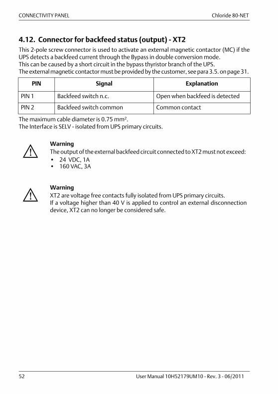
4.12. Connector for backfeed status (output) - XT2This 2-pole screw connector is used to activate an external magnetic contactor (MC) if theUPS detects a backfeed current through the Bypass in double conversion mode.This can be caused by a short circuit in the bypass thyristor branch of the UPS.The external magnetic contactor must be provided by the customer, see para 3.5. on page 31.
The maximum cable diameter is 0.75 mm2.The Interface is SELV - isolated from UPS primary circuits.
PIN Signal Explanation
PIN 1 Backfeed switch n.c. Open when backfeed is detected
PIN 2 Backfeed switch common Common contact
WarningThe output of the external backfeed circuit connected to XT2 must not exceed: • 24 VDC, 1A• 160 VAC, 3A
WarningXT2 are voltage free contacts fully isolated from UPS primary circuits.If a voltage higher than 40 V is applied to control an external disconnectiondevice, XT2 can no longer be considered safe.
Chloride 80-NET Normal and safe operation
User Manual 10H52179UM10 - Rev. 3 - 06/2011 53
5. NORMAL AND SAFE OPERATION
5.1. FunctionThe uninterruptible power supply (UPS) is connected between line power and electrical load.It protects the load from line power interruptions and power failures.
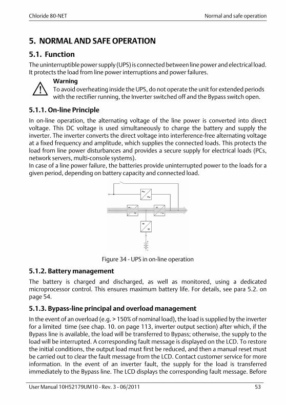
5.1.1. On-line Principle
In on-line operation, the alternating voltage of the line power is converted into directvoltage. This DC voltage is used simultaneously to charge the battery and supply theinverter. The inverter converts the direct voltage into interference-free alternating voltageat a fixed frequency and amplitude, which supplies the connected loads. This protects theload from line power disturbances and provides a secure supply for electrical loads (PCs,network servers, multi-console systems).In case of a line power failure, the batteries provide uninterrupted power to the loads for agiven period, depending on battery capacity and connected load.
Figure 34 - UPS in on-line operation
5.1.2. Battery management
The battery is charged and discharged, as well as monitored, using a dedicatedmicroprocessor control. This ensures maximum battery life. For details, see para 5.2. onpage 54.
5.1.3. Bypass-line principal and overload management
In the event of an overload (e.g. > 150% of nominal load), the load is supplied by the inverterfor a limited time (see chap. 10. on page 113, inverter output section) after which, if theBypass line is available, the load will be transferred to Bypass; otherwise, the supply to theload will be interrupted. A corresponding fault message is displayed on the LCD. To restorethe initial conditions, the output load must first be reduced, and then a manual reset mustbe carried out to clear the fault message from the LCD. Contact customer service for moreinformation. In the event of an inverter fault, the supply for the load is transferredimmediately to the Bypass line. The LCD displays the corresponding fault message. Before
WarningTo avoid overheating inside the UPS, do not operate the unit for extended periodswith the rectifier running, the Inverter switched off and the Bypass switch open.

Normal and safe operation Chloride 80-NET
54 User Manual 10H52179UM10 - Rev. 3 - 06/2011
carrying out a manual reset to restore initial conditions, it is necessary to remove the rootcause of the fault. It is strongly recommended you contact customer support for moreinformation.
5.1.4. Communication
The UPS offers several interfaces for communication with computers. Further information isincluded in chap. 4. on page 45.
5.2. Special features
5.2.1. Safe and reliable operation
• Real on-line functioning, i.e. complete de-coupling of the load from all abnormalities inline power
• Important features of the UPS, such as vector control and high flexibility, are supportedby the DSP board).
• Static Bypass Switch increases the reliability of electrical supply
5.2.2. Easy installation and operation
• Parameterisation using bundled PC software• No Operator presence required during normal operation• Simple LCD provides clear indication of status, load and battery quality. The concept
behind the display and the way it operates is easy to understand.• Event memory for fault analysis• Fault display and audible signal
5.2.3. Battery management
• Automatic battery management ensures maximum battery life• Automatic battery circuit test• Temperature-dependent charging
5.2.4. Environment, EMC
• EMC limits values to comply with European regulations and standards• Energy savings due to high efficiency• Low noise level• Special EMC filter for higher demands (optional)
5.2.5. Modern technology
• Interfaces with software for all operating systems• IGBT power transistors• Highly integrated digital electronics (ASICs)• Especially well suited for computer loadsThe UPS can also be used as a frequency converter for 50/60 Hz or vice versa.
Chloride 80-NET Normal and safe operation
User Manual 10H52179UM10 - Rev. 3 - 06/2011 55
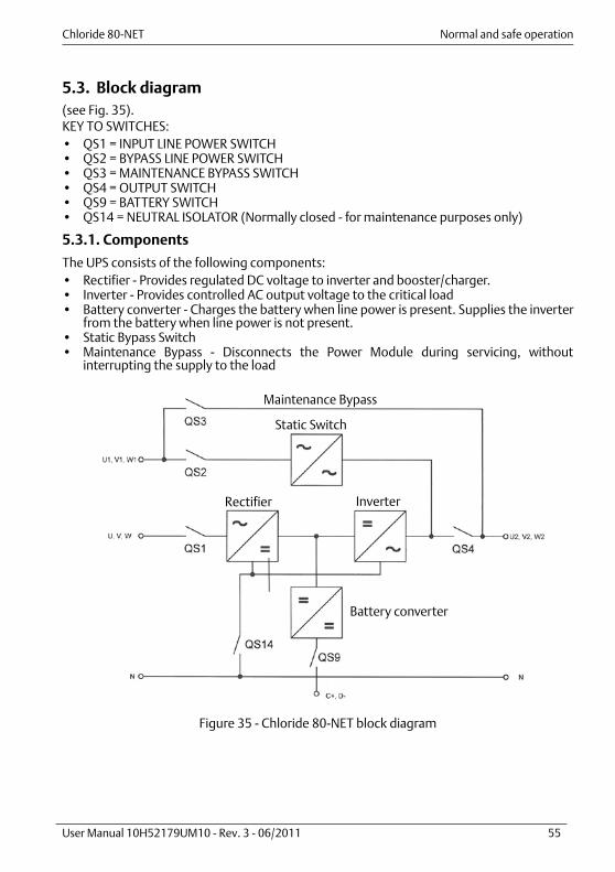
5.3. Block diagram(see Fig. 35).KEY TO SWITCHES:• QS1 = INPUT LINE POWER SWITCH• QS2 = BYPASS LINE POWER SWITCH• QS3 = MAINTENANCE BYPASS SWITCH• QS4 = OUTPUT SWITCH• QS9 = BATTERY SWITCH• QS14 = NEUTRAL ISOLATOR (Normally closed - for maintenance purposes only)
5.3.1. Components
The UPS consists of the following components: • Rectifier - Provides regulated DC voltage to inverter and booster/charger.• Inverter - Provides controlled AC output voltage to the critical load• Battery converter - Charges the battery when line power is present. Supplies the inverter
from the battery when line power is not present.• Static Bypass Switch• Maintenance Bypass - Disconnects the Power Module during servicing, without
interrupting the supply to the load
Figure 35 - Chloride 80-NET block diagram
Static Switch
InverterRectifier
Battery converter
Maintenance Bypass

Normal and safe operation Chloride 80-NET
56 User Manual 10H52179UM10 - Rev. 3 - 06/2011
5.4. Maintenance Bypass Chloride 80-NET is equipped with a Maintenance Bypass Switch (QS3) that allows the user toperform maintenance on the UPS without interrupting the supply to the load.Transfer to and from Maintenance must be done in accordance with the procedures 3 and 4described in para 5.7. on page 60.• QS1 = OPEN• QS2 = OPEN• QS3 = CLOSED• QS4 = OPEN• QS9 = OPEN(see Fig. 16, Fig. 17, Fig. 18 and Fig. 19)
5.5. Operating modesThe UPS has four different operating modes. These are described below.
5.5.1. On-line operation
Normal UPS operating mode. The connected loads are supplied from line power via theInverter. The batteries are charged as necessary. The inverter reliably filters line powerdisturbances and provides a stable, interference-free supply to the load. On 60-200 kVArated versions, “OK” lights up when the UPS is operating in the on-line mode. On 300-500kVA rated versions, the Normal state is displayed.In this operating mode, the UPS switches to battery operation if a line power failure occurs.If an overload or short circuit occurs on the UPS output, or if there is a fault in the inverter,the UPS switches to Bypass operation.
Figure 36 - Power flow in on-line operation
WarningDuring parallel operation, switching of the load on the built-in service bypassmust be performed by an external device (see chap. 8. on page 99).

Chloride 80-NET Normal and safe operation
User Manual 10H52179UM10 - Rev. 3 - 06/2011 57
5.5.2. Battery operation
In this operating mode, the connected load is supplied from the batteries via the inverter. Inthe event of power failure, battery operation is automatically activated and supplies theloads without interruption. If the power failure lasts longer than 30 s, the UPS signals a faultcondition. On 60-200 kVA rated versions, when the UPS is operating in the battery mode,the “OK” LED (green) on the control panel lights up and the “ALARM” LED (yellow) flashes.On 300-500 kVA rated versions, the battery's operating condition is displayed. From thisoperating mode, the UPS automatically reverts to on-line operation within the backup timeafter the line power returns. If the duration of the power failure is longer than batterycapacity under current load, the UPS provides the relative information via its interfaces.Computers can be automatically powered down with additional software (optional).
Figure 37 - Power flow during battery operation
5.5.3. Bypass operation
In this operating mode, the connected loads are supplied from line power via the StaticBypass Switch. The Static Bypass Switch is used to provide power to the loads. If an overloador short-circuit on UPS output occurs, the Static Bypass Switch is automatically activated toprovide uninterrupted power to the loads. On 60-200 kVA rated versions, the “ALARM” LED(yellow) on the control panel lights up. On 300-500 kVA rated versions, the Bypass operatingcondition is displayed. From this operating mode, the UPS automatically reverts to on-lineoperation after the fault is corrected.Bypass operation can also be specifically selected from the control panel using the pushbutton.
Figure 38 - Power flow in Bypass operation

Normal and safe operation Chloride 80-NET
58 User Manual 10H52179UM10 - Rev. 3 - 06/2011
5.5.4. Digital interactive mode
If priority has been set to the digital interactive mode, intelligent double conversiontechnology will enable Chloride 80-NET to continuously monitor the condition of the inputsupply (including its failure rate) to ensure maximum reliability for critical users. On the basisof the analysis performed, it decides whether to supply the load through the direct line orthe conditioned line. This operational mode, which offers significant energy savings byincreasing overall AC/AC efficiency of the UPS, is primarily intended for general purpose ICTapplications. However, it does not provide the same output power quality as compared withUPS operation in the double conversion mode. Therefore it must be determined whetherthis mode is appropriate for special applications. Digital interactive mode is not available forparallel systems.
5.5.5. Maintenance Bypass
In this operating mode, the connected loads are supplied directly from line power. TheDisplay/Control Panel is disabled.Maintenance Bypass is used to supply the connected loads during maintenance work on theUPS.
Figure 39 - Power flow during service Bypass operation
5.6. Placement into service
5.6.1. Forming
If the UPS devices have not been used for one year or more, the intermediate circuitcapacitors must be reformed. If the UPS devices are placed into service within one year afterdelivery (check nameplate), this action is not necessary.
Contact customer service if the intermediate circuit capacitors must be reformed.
Carry out placement into service as follows:
Chloride 80-NET Normal and safe operation
User Manual 10H52179UM10 - Rev. 3 - 06/2011 59
5.6.2. Switch on the UPS
• Check that the UPS is connected according to chap. 3. on page 21. For parallel operationplease check chap. 8. on page 99.
• Make sure the ventilation grilles are unobstructed• Make sure the ground connection is in place• Make sure that any external switches are in the OFF (0) position and that the UPS is
completely de-energized• Make sure that any external batteries are disconnected
5.6.3. Connect the batteries
Before the system starts, make sure that UPS battery connection polarity is correct. Wrongconnections can damage the system and endanger operator safety.
5.6.4. Switch to on-line operation
• Set the UPS to On-line Operation (see para 5.7 on page 60).
WarningDo not connect any devices that may overload the UPS or draw direct currentfrom it.
NoticeIf these instructions are not observed correctly, problems may occur with thesupply of power.
WarningThis operation must be carried out by authorized personnel.To prevent damage to the system, before closing QS9, use a suitable instrument to make sure that the polarity of the battery voltage measured on the external side of QS9 matches the polarity indicated in (see Fig. 21-Fig. 27).
WarningClose QS9 only after battery polarity has been carefully checked.

Normal and safe operation Chloride 80-NET
60 User Manual 10H52179UM10 - Rev. 3 - 06/2011
5.7. UPS switching proceduresProcedures refer to para 5.3. on page 55.
5.7.1. Procedure 1: UPS TURN-ON PROCEDURE
Starting with the UPS completely deenergized, this procedure explains how to switch on theUPS and set it to Normal Operating Mode.
5.7.2. Procedure 2: UPS TURN-OFF PROCEDURE
Starting with the UPS in the Normal Mode, this procedure explains how to switch off the UPS.When this procedure is followed, the output voltage is completely turned off and any loadconnected to UPS output is shut down.
Step Action Status
1 Switch QS1 to the ON position Rectifier start up2 Switch QS2 to the ON position (wait for the Static Bypass
Switch to switch on)Static Bypass Switch ON and fans ON
3 Close external battery switches then switch QS9 to the ON position
4 Switch QS4 to the ON positionIMPORTANT: when QS4 is closed, the output of the UPS and all the loads connected to it will be energized.
System in Bypass Mode - Output voltage present
5 On the 60-200 kVA version, press the “Start Inverter” button on the monitor panel (for approx. 5 seconds). On the 300-500 kVA version, touch the “Start Inverter” icon on the LCD touch screen.
Normal Mode
Step Action Status
1 On the 60-200 kVA version, press the “Stop Inverter” button on the monitor panel (for approx. 5 seconds). On the 300-500 kVA version, touch the “Stop Inverter” icon on the LCD touch screen.
System in Bypass Mode
2 Switch QS9 to the OFF position3 Switch QS4 to the OFF position Load not supplied4 Switch QS2 to the OFF position5 Switch QS1 to the OFF position
Chloride 80-NET Normal and safe operation
User Manual 10H52179UM10 - Rev. 3 - 06/2011 61
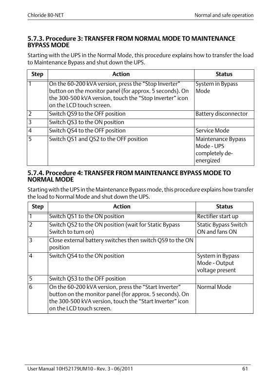
5.7.3. Procedure 3: TRANSFER FROM NORMAL MODE TO MAINTENANCE BYPASS MODE
Starting with the UPS in the Normal Mode, this procedure explains how to transfer the loadto Maintenance Bypass and shut down the UPS.
5.7.4. Procedure 4: TRANSFER FROM MAINTENANCE BYPASS MODE TO NORMAL MODE
Starting with the UPS in the Maintenance Bypass mode, this procedure explains how transferthe load to Normal Mode and shut down the UPS.
Step Action Status
1 On the 60-200 kVA version, press the “Stop Inverter” button on the monitor panel (for approx. 5 seconds). On the 300-500 kVA version, touch the “Stop Inverter” icon on the LCD touch screen.
System in Bypass Mode
2 Switch QS9 to the OFF position Battery disconnector3 Switch QS3 to the ON position4 Switch QS4 to the OFF position Service Mode5 Switch QS1 and QS2 to the OFF position Maintenance Bypass
Mode - UPS completely de-energized
Step Action Status
1 Switch QS1 to the ON position Rectifier start up2 Switch QS2 to the ON position (wait for Static Bypass
Switch to turn on)Static Bypass Switch ON and fans ON
3 Close external battery switches then switch QS9 to the ON position
4 Switch QS4 to the ON position System in Bypass Mode - Output voltage present
5 Switch QS3 to the OFF position6 On the 60-200 kVA version, press the “Start Inverter”
button on the monitor panel (for approx. 5 seconds). On the 300-500 kVA version, touch the “Start Inverter” icon on the LCD touch screen.
Normal Mode

Normal and safe operation Chloride 80-NET
62 User Manual 10H52179UM10 - Rev. 3 - 06/2011
5.8. Inverter STOP/START procedures
5.8.1. Single UPS - Start Inverter
UPS in Bypass mode: To start the inverter and transfer the load to the inverter, press the“Start Inverter” button on the display (for 60-200 kVA versions) or touch the ‘Start Inverter’icon on the LCD touch screen (for 300-500 kVA versions).
5.8.2. Single UPS - Stop Inverter
UPS in normal mode: To stop the inverter and transfer the load to the Bypass line, press the“Stop Inverter” button on the display (for 60-200 kVA versions) or touch the ‘Stop Inverter’icon on the LCD touch screen (for 300-500 kVA versions) .
5.8.3. Parallel UPS system - Start Inverter
System in Bypass mode: To start all the inverters and transfer the load to the inverters, pressthe “Start Inverter” button on the display (for 60-200 kVA versions) or touch the ‘StartInverter’ icon on the LCD touch screen (for 300-500 kVA versions) on each machine. Theinverters will start when all Start Inverter commands have been given.
5.8.4. Parallel UPS system - Stop Inverter
System in normal mode: To shut down all the inverters and transfer the load to the Bypassline, press the “Stop Inverter” button on the display (for 60-200 kVA versions) or touch the‘Stop Inverter’ icon on the LCD touch screen (for 300-500 kVA versions) on each machine.The inverters will shut down when all Stop Inverter commands have been given.

Chloride 80-NET OPERATOR INTERFACE PANEL
User Manual 10H52179UM10 - Rev. 3 - 06/2011 63
6. OPERATOR INTERFACE PANEL
6.1. Chloride 80-NET 60-200 kVA
Figure 40 - Chloride 80-NET 60-200 kVA - operator interface panel
LEGEND1 Left button 2 Up button3 Down button 4 Right button5 Start Inverter button 6 Stop Inverter button7 System Normal LED 8 Warning LED9 Alarm LED 10 Reset button
DISPLAY
12
4
63
5
9
7
8 10

OPERATOR INTERFACE PANEL Chloride 80-NET
64 User Manual 10H52179UM10 - Rev. 3 - 06/2011
6.1.1. Description of Control Panel Functions
‚Ä¢ Start InverterPress the “Start Inverter” button for 5 seconds.
‚Ä¢ Stop InverterPress the “Stop Inverter” button for 5 seconds.The UPS can be manually switched between Bypass and on-line operation using the keys“Start Inverter” (I) and “Stop Inverter” (O).
• Silencing the BuzzerTo silence the Buzzer, press the Reset button momentarily
• Reset buttonTo restore normal UPS operation after a fault condition, correct the situation that caused thefault and then press the Reset button for at least one second. If a fault occurs, pressing the button mutes the audible alarm. After the fault has beencorrected, pressing the button a second time resets the fault message and restores UPSoperation.
• General Status LEDThree LED indicators provide a quick, general understanding of the status of the UPS, asdescribed below:
OK LED (green) Normal Operation
When this light is on steadily (not flashing), the system is runningnormally and no warnings or alarms are present. During line powerfailures (and with all other conditions being nominal), this LED willflash.
Warning LED (yellow) Warning Condition(s) present
This indication is activated by abnormal conditions which could affectnormal UPS operation. These conditions do not originate with theUPS, but may be caused either by the surrounding environment or bythe electrical installation (line power side and load side). A descriptionof the active warning(s) can be viewed by browsing the relevant LCDdisplay menus.
Alarm LED (red) Alarm Condition
When this light is on, immediate attention should be given to theseverity of the alarm, and service should be called promptly. Adescription of the active alarm(s) can be viewed by browsing therelevant LCD display menus.

Chloride 80-NET OPERATOR INTERFACE PANEL
User Manual 10H52179UM10 - Rev. 3 - 06/2011 65
6.1.2. Display
The Display provides the user with a range of information and functions that can be accessedusing control panel navigation keys 1 to 4 (see Fig. 40 on page 63).UPS modifications and settings must be made by qualified technicians, only. Settings shouldbe tested only if the loads connected to the UPS are non-critical.$
The Main Page displays a block diagram of the UPS and uses standard technical symbols toindicate current operating status (e.g. on-line operation, battery operation, Bypassoperation, etc.), load level, and remaining backup time. To access the Main Menu page fromthe Main (default) page, press the Right soft key (key 4 - see Fig. 40 on page 63). From thismenu, you can scroll through the various sub-menus using the Up and Down soft keys (2 and3). Press the Right soft key to select any menu from the list, and the Left soft key (1) to returnto the Main Menu page.The table on the following page provides a summary of the sub-menus.
When the UPS is not in the normal operating mode, you can access the "Warning and Alarm"summary page directly from the Main (default) page. Warnings and alarms are identified bytext strings and codes (see Table 6 on page 72 and Table 7 on page 75). During batterypowered operation, the display switches between warning code and estimated backup time(minutes).

OPERATOR INTERFACE PANEL Chloride 80-NET
66 User Manual 10H52179UM10 - Rev. 3 - 06/2011
Table 5: Display menu summary
Menu Sub-menus Information/Functions
Actual values • Line power Input• Bypass Input• DC Link• UPS Output• Battery
Provides information about the input, Bypass and output voltages and frequencies; line power failures; output current and power; DC stage parameters; inverter operation; and battery condition.
Status • Rectifier• Boost• Battery• Battery Charger• Inverter• Bypass• Load
Provides status information about the main UPS blocks.
Battery test • Test Status• Perform a Test
Provides information about battery status and enables you to perform a battery test. You can select the length of the battery test from the list that appears.
LIFE • Next call date• Next call time• Delayed call after• Connection status• Call Type• Service Mode
Provides status information about LIFE, and allows you to reset a delayed call; perform a manual call; and select service mode.
Language Allows you to select the display language from: English; German; French; Italian; Spanish; Portuguese; Chinese; Turkish.
Guide procedure
• Manual Bypass• Return from Bypass• Start up• Shut down
Procedures to guide the operator through specific functions.
About • Manufacturer• Type of UPS• Website• Firmware Code/Rev./Date
Provides miscellaneous information about the UPS, including the code, revision and release date for the various firmware versions.

Chloride 80-NET OPERATOR INTERFACE PANEL
User Manual 10H52179UM10 - Rev. 3 - 06/2011 67
6.1.3. Sample guided procedure for switching the UPS from Normal Mode to Maintenance Bypass - Manual Bypass
When the desired procedure is selected from the Guided Procedures menu (in this case theSingle UPS Manual Bypass procedure), the following window appears in the display andshows the principle UPS components and their current status:
The various UPS switches are also shown. The Maintenance Bypass switch, QS3, is shown inthe open (OFF) position in the above example. Flashing icons inform the operator that thecorresponding switch must be opened or closed.
In the event of a fault, a warning message is displayed (see para 6.1.4. on page 71 for full listof warning messages). Exit the procedure, correct the fault and reset before proceeding.Pressing the button identified by the “Exit” message at any time interrupts the procedure.
In this example, the “Stop Inverter" message appears in the bottom right of the display, and
the Stop symbol flashes over the Inverter, indicating that the user must shut down theInverter by pressing the corresponding button on the panel. (See “Instruction messages” onpage 71 for full list of instruction messages).
Exit
Stop
Inverter
Manual Bypass
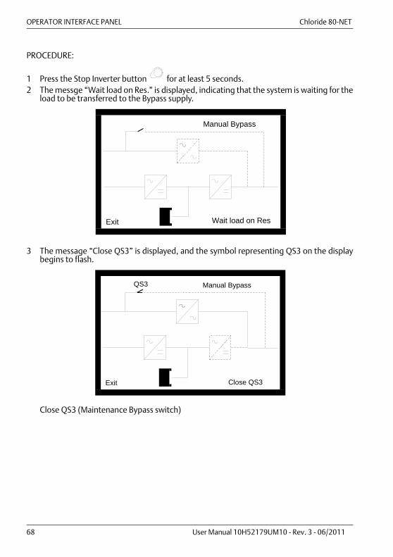
OPERATOR INTERFACE PANEL Chloride 80-NET
68 User Manual 10H52179UM10 - Rev. 3 - 06/2011
PROCEDURE:
1 Press the Stop Inverter button for at least 5 seconds.2 The messge “Wait load on Res.” is displayed, indicating that the system is waiting for the
load to be transferred to the Bypass supply.
3 The message “Close QS3” is displayed, and the symbol representing QS3 on the displaybegins to flash.
Close QS3 (Maintenance Bypass switch)
Exit Wait load on Res
Manual Bypass
Exit Close QS3
Manual BypassQS3
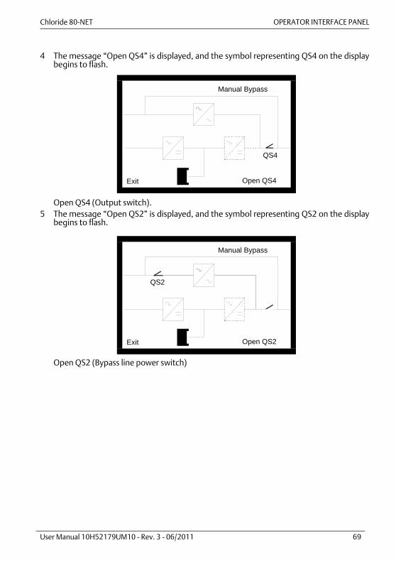
Chloride 80-NET OPERATOR INTERFACE PANEL
User Manual 10H52179UM10 - Rev. 3 - 06/2011 69
4 The message “Open QS4” is displayed, and the symbol representing QS4 on the displaybegins to flash.
Open QS4 (Output switch).5 The message “Open QS2” is displayed, and the symbol representing QS2 on the display
begins to flash.
Open QS2 (Bypass line power switch)
Exit Open QS4
Manual Bypass
QS4
Exit Open QS2
Manual Bypass
QS2
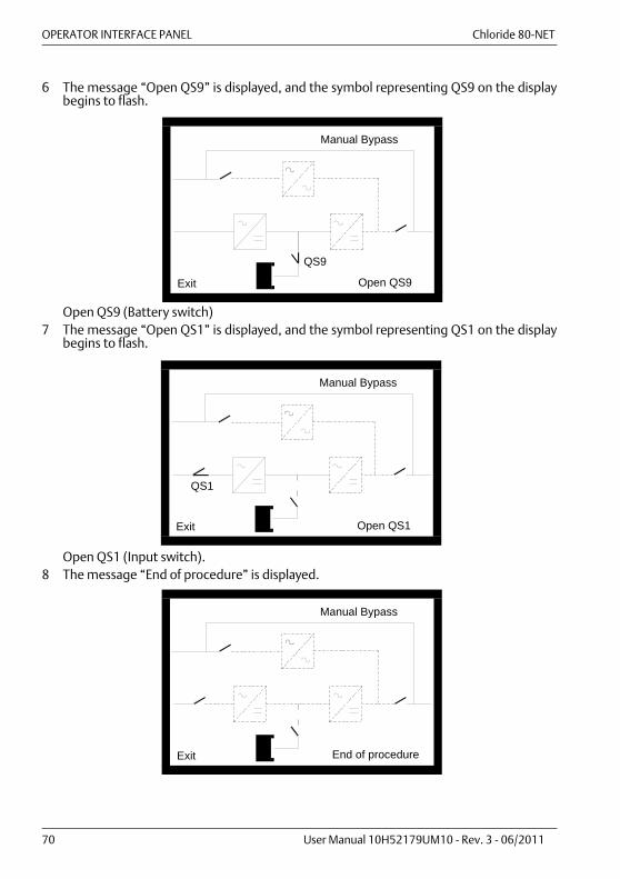
OPERATOR INTERFACE PANEL Chloride 80-NET
70 User Manual 10H52179UM10 - Rev. 3 - 06/2011
6 The message “Open QS9” is displayed, and the symbol representing QS9 on the displaybegins to flash.
Open QS9 (Battery switch)7 The message “Open QS1” is displayed, and the symbol representing QS1 on the display
begins to flash.
Open QS1 (Input switch).8 The message “End of procedure” is displayed.
Exit Open QS9
Manual Bypass
QS9
Exit Open QS1
Manual Bypass
QS1
Exit End of procedure
Manual Bypass
Chloride 80-NET OPERATOR INTERFACE PANEL
User Manual 10H52179UM10 - Rev. 3 - 06/2011 71
Instruction messages
6.1.4. Warning messages
Stop Inverter Open QS1 Close QS1
Start Inverter Open QS2 Close QS2
Press Exit Open QS3 Close QS3
Reset Fault Open QS4 Close QS4
Open QS9 Close QS9
Procedure not OK
VDC wait OK
Waiting Bypass ON
Wait for Load on Bypass
Wait for Load on Inverter

OPERATOR INTERFACE PANEL Chloride 80-NET
72 User Manual 10H52179UM10 - Rev. 3 - 06/2011
6.1.5. Warning and Fault indications
The UPS recognizes and calls attention to a number of events occurring during operation.These events are divided into Warning and Fault indications. Whether the message is awarning or fault can be determined from the number which appears in the Warning/FaultDiagnosis page of the display, and the way the buzzer sounds.
BuzzerThe buzzer has two different patterns, which indicate the type of warning.• Pattern 1: long intervals - This event is less serious. It is not essential that the cause be
corrected immediately, unless otherwise specified on the "Warning indicators" table.• Pattern 2: short intervals - This is a serious event. The cause should be rectified right
away to avoid a fault condition.The buzzer is silenced automatically as soon as the cause of the event is corrected. It can alsobe silenced manually by pressing the TEST/RESET button.
Warning indicatorsIf a warning indication appears, the UPS will continue to operate. The yellow warning LED willlight up on the control panel. A number will appear in the display to indicate the type ofwarning.
Displayed WarningsThe various possible warning indications are listed on the table below:
Table 6: Warning Indications
DSP STAGEID MESSAGE
W1.1 Placement into service or test modeW1.2 Maintenance Bypass switch closedW1.3 Fan life exceededW1.5 Synchronization system faultW1.6 DIC Power-upW1.7 System shutdown (DIC generated)W1.8 ID card missingW1.9 Calibration started
W1.10 Input air high temperatureW1.11 Input air temp. out of rangeW1.12 Neutral-Booster stab. over-temp.W1.13 Neutral switch openW1.14 SBS output switch openW1.15 SBS Bypass switch closedW1.16 Do not insert battery switch
RECTIFIER STAGEID MESSAGE
W1.1 Line power switch open

Chloride 80-NET OPERATOR INTERFACE PANEL
User Manual 10H52179UM10 - Rev. 3 - 06/2011 73
W1.2 Primary line power failureW1.3 Overload warningW1.4 Primary line power wrong phase rotationW1.5 DC voltage lowW1.6 Rectifier over-temperatureW1.7 Out of synchronization
INVERTER STAGEID MESSAGE
W1.1 Inv. overtemperature warningW1.2 DC undervoltageW1.3 Overload warningW1.4 Inverter off warningW1.5 Inv. off pending commandW1.6 Inv. on pending commandW3.1 Current limitW3.2 kW protectionW3.3 Inv. off for shutdown command
BYPASS STAGEID MESSAGE
W1.1 Bypass switch openW1.2 Bypass line power failureW1.3 Overload warningW1.4 Bypass wrong phase rotationW1.5 Bypass disabled for DC voltage lowW1.6 Bypass over-temperature warning
BATTERY STAGEID MESSAGE
W1.1 Battery switch openW1.3 Imminent end of autonomy timeW1.5 Battery end of dischargeW1.7 High battery temperatureW1.8 Battery temp. out of rangeW1.9 Temp. probe not responding
W1.10 Battery autonomy testLOAD STAGE
ID MESSAGEW1.1 Output switch open
Table 6: Warning Indications

OPERATOR INTERFACE PANEL Chloride 80-NET
74 User Manual 10H52179UM10 - Rev. 3 - 06/2011
W1.2 Output load not suppliedW1.3 Retransfer inhibitedW1.4 Load supplied by BypassW1.5 Load supp. by maintenance Bypass
BATTERY CHARGER STAGEID MESSAGE
W1.1 Charger communication lostW1.2 Actual values differ from set onesW1.3 Charger on cmd but input volt. lowW1.4 Chg. on and chg. out. short circ.W1.5 Chg. off and chg. out. short circ.W1.6 Charger detects no batt. connectedW1.7 Chg. forced on, volt. not raisingW1.8 Charger detects reversed polarity
BOOST STAGEID MESSAGE
W1.1 DC voltage lowW1.2 Booster-charger over-temperature
Table 6: Warning Indications
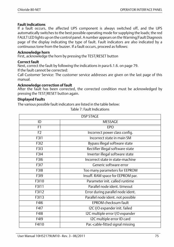
Chloride 80-NET OPERATOR INTERFACE PANEL
User Manual 10H52179UM10 - Rev. 3 - 06/2011 75
Fault indicationsIf a fault occurs, the affected UPS component is always switched off, and the UPSautomatically switches to the best possible operating mode for supplying the loads; the redFAULT LED lights up on the control panel. A number appears on the Warning/Fault Diagnosispage of the display indicating the type of fault. Fault indicators are also indicated by acontinuous tone from the buzzer. If a fault occurs, proceed as follows:
Acknowledge hornFirst, acknowledge the horn by pressing the TEST/RESET button
Correct faultNext, correct the fault by following the indications in para 6.1.6. on page 79.If the fault cannot be corrected:Call Customer Service: The customer service addresses are given on the last page of thismanual.
Acknowledge correction of faultAfter the fault has been corrected, the corrected condition must be acknowledged bypressing the TEST/RESET button again.
Displayed FaultsThe various possible fault indicators are listed in the table below:
Table 7: Fault Indications
DSP STAGEID MESSAGEF1 EPOF2 Incorrect power class config.
F3I1 Incorrect state in main SMF3I2 Bypass illegal software stateF3I3 Rectifier illegal software stateF3I4 Inverter illegal software stateF3I6 Incorrect state in state-machineF3I7 Generic software errorF3I8 Too many parameters for EEPROMF3I9 Insuff. RAM space for EEPROM par.
F3I10 Parameter init. called runtimeF3I11 Parallel node ident. timeoutF3I12 Error during parallel node ident.F3I13 Parallel node ident. not possibleF4I6 EPROM checksum faultF4I7 I2C I/O expander init. failedF4I8 I2C multiple error I/O expanderF4I9 I2C multiple error ID card
F4I10 Par.-cable-fitted signal missing
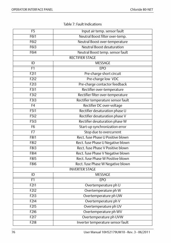
OPERATOR INTERFACE PANEL Chloride 80-NET
76 User Manual 10H52179UM10 - Rev. 3 - 06/2011
F5 Input air temp. sensor faultF6I1 Neutral Boost filter over-temp.F6I2 Neutral Boost over-temperatureF6I3 Neutral Boost desaturationF6I4 Neutral Boost temp. sensor fault
RECTIFIER STAGEID MESSAGEF1 EPO
F2I1 Pre-charge short circuitF2I2 Pre-charge low VDCF2I3 Pre-charge contactor feedbackF3I1 Rectifier over-temperatureF3I2 Rectifier filter over-temperatureF3I3 Rectifier temperature sensor faultF4 Rectifier DC over-voltage
F5I1 Rectifier desaturation phase UF5I2 Rectifier desaturation phase VF5I3 Rectifier desaturation phase WF6 Start-up synchronization errorF7 Stop due to overcurrent
F8I1 Rect. fuse Phase U Positive blownF8I2 Rect. fuse Phase U Negative blownF8I3 Rect. fuse Phase V Positive blownF8I4 Rect. fuse Phase V Negative blownF8I5 Rect. fuse Phase W Positive blownF8I6 Rect. fuse Phase W Negative blown
INVERTER STAGEID MESSAGEF1 EPO
F2I1 Overtemperature ph UF2I2 Overtemperature ph WF2I3 Overtemperature ph UWF2I4 Overtemperature ph VF2I5 Overtemperature ph UVF2I6 Overtemperature ph WVF2I7 Overtemperature ph UVWF2I8 Inverter temperature sensor fault
Table 7: Fault Indications

Chloride 80-NET OPERATOR INTERFACE PANEL
User Manual 10H52179UM10 - Rev. 3 - 06/2011 77
F2I9 Inverter filter over-temperatureF3I1 Multiple inv. overcurr. cut offF3I2 Inv. stopped due to overcurrentF3I3 kW protectionF4 DC BUS overvoltage
F5I1 Output overvoltageF5I2 Output undervoltageF5I3 Output freq. out of limitsF5I4 Output short circuitF5I5 DC component phase UF5I6 DC component phase VF5I7 DC component phase WF6I1 DC/AC desaturation ph. UF6I2 DC/AC desaturation ph. VF6I3 DC/AC desaturation ph. WF7 Battery thyristor fault
BYPASS STAGEID MESSAGEF1 EPO
F2I1 Broken byp. or V_Byp measurementF2I2 Bypass ready signal failureF3 Backfeed protection active
F4I1 Bypass over-temperatureF4I2 Bypass temperature sensor fault
F5 Bypass overload timeoutF6 Bypass line power failed during DLSF7 Parallel byp. failure during DLS
BATTERY STAGEID MESSAGEF1 Battery reverse polarityF2 Battery overvoltageF3 Battery test faultF4 Battery fuse blown
BATTERY CHARGER STAGEID MESSAGEF1 Charger communic. not possibleF2 Charger over-current
Table 7: Fault Indications
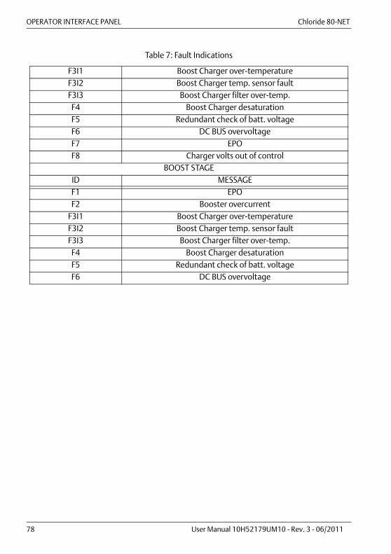
OPERATOR INTERFACE PANEL Chloride 80-NET
78 User Manual 10H52179UM10 - Rev. 3 - 06/2011
F3I1 Boost Charger over-temperatureF3I2 Boost Charger temp. sensor faultF3I3 Boost Charger filter over-temp.F4 Boost Charger desaturationF5 Redundant check of batt. voltageF6 DC BUS overvoltageF7 EPOF8 Charger volts out of control
BOOST STAGEID MESSAGEF1 EPOF2 Booster overcurrent
F3I1 Boost Charger over-temperatureF3I2 Boost Charger temp. sensor faultF3I3 Boost Charger filter over-temp.F4 Boost Charger desaturationF5 Redundant check of batt. voltageF6 DC BUS overvoltage
Table 7: Fault Indications
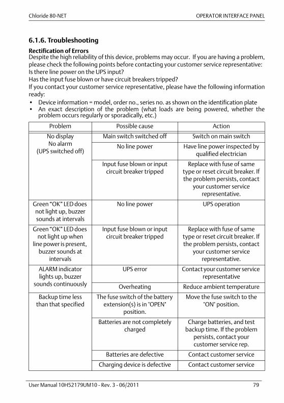
Chloride 80-NET OPERATOR INTERFACE PANEL
User Manual 10H52179UM10 - Rev. 3 - 06/2011 79
6.1.6. Troubleshooting
Rectification of ErrorsDespite the high reliability of this device, problems may occur. If you are having a problem,please check the following points before contacting your customer service representative:Is there line power on the UPS input?Has the input fuse blown or have circuit breakers tripped? If you contact your customer service representative, please have the following informationready:• Device information = model, order no., series no. as shown on the identification plate• An exact description of the problem (what loads are being powered, whether the
problem occurs regularly or sporadically, etc.)
Problem Possible cause Action
No displayNo alarm
(UPS switched off)
Main switch switched off Switch on main switch
No line power Have line power inspected by qualified electrician
Input fuse blown or input circuit breaker tripped
Replace with fuse of same type or reset circuit breaker. If the problem persists, contact
your customer service representative.
Green “OK” LED does not light up, buzzer sounds at intervals
No line power UPS operation
Green “OK” LED does not light up when
line power is present, buzzer sounds at
intervals
Input fuse blown or input circuit breaker tripped
Replace with fuse of same type or reset circuit breaker. If the problem persists, contact
your customer service representative.
ALARM indicator lights up, buzzer
sounds continuously
UPS error Contact your customer service representative
Overheating Reduce ambient temperature
Backup time less than that specified
The fuse switch of the battery extension(s) is in "OPEN"
position.
Move the fuse switch to the "ON" position.
Batteries are not completely charged
Charge batteries, and test backup time. If the problem
persists, contact your customer service rep.
Batteries are defective Contact customer service
Charging device is defective Contact customer service
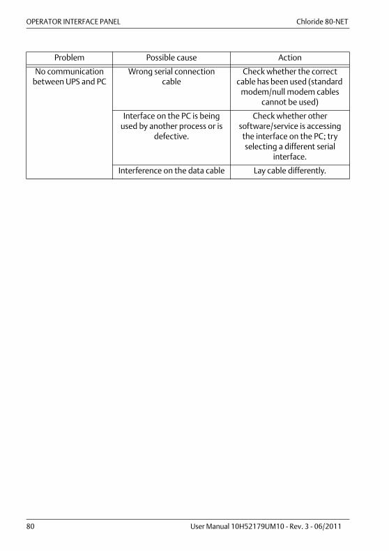
OPERATOR INTERFACE PANEL Chloride 80-NET
80 User Manual 10H52179UM10 - Rev. 3 - 06/2011
No communication between UPS and PC
Wrong serial connection cable
Check whether the correct cable has been used (standard
modem/null modem cables cannot be used)
Interface on the PC is being used by another process or is
defective.
Check whether other software/service is accessing
the interface on the PC; try selecting a different serial
interface.
Interference on the data cable Lay cable differently.
Problem Possible cause Action

Chloride 80-NET OPERATOR INTERFACE PANEL
User Manual 10H52179UM10 - Rev. 3 - 06/2011 81
6.2. Chloride 80-NET 300-500 kVAThe Chloride 80-NET 300/400/500 kVA operator interface for controlling and testing themachine state includes an LCD touch screen.When you approach Chloride 80-NET 300/400/500 kVA, remember that the touch screenmay be in Screensaver mode. Touch the screen to bring up the main page on the display.Several menu items can be accessed from the main display screen. These menu items aredetailed in subsequent sections.
Figure 41 - Chloride 80-NET 300-500 kVA - operator interface panel
Descriptions1. Bypass Input: voltage and frequency readings2. Line power Input: voltage, current and frequency readings3. Output: voltage, current and frequency readings4. Battery: voltage and current readings5. System Status:System Normal Indicator (Normal Operation): when the green status box appears, thismeans that the system is operating normally and that no warning or alarm has occurred.During line power failures (with all other conditions being nominal), this box is replaced by ayellow triangle.Warning Indicator (Warning Condition(s) present): this indication is activated by thepresence of abnormal conditions which could affect the normal operation of the UPS. Theseconditions do not originate with the UPS, but may be caused either by the surroundingenvironment or by the electrical installation (line power side and load side). A description ofthe active warning(s) can be viewed by clicking on the yellow triangle or using the warningand fault button at the bottom of the page.
1
2
3
4
5
6
7
8
9

OPERATOR INTERFACE PANEL Chloride 80-NET
82 User Manual 10H52179UM10 - Rev. 3 - 06/2011
Fault Indicator (Alarm Condition): when the red circle with white cross appears,immediate attention should be given to the severity of the alarm, and service should becalled promptly. A description of the active alarm(s) can be viewed by clicking on thewarning and fault button at the bottom of the page.
Regardless of which indicator is active, all available diagnostic information on the unit can bedisplayed by touching this area.
6. Control Buttons:Start Inverter and Stop Inverter : the touch screen display features two separatebuttons for starting and shutting down the inverter. The start/stop control incorporates asafety feature for preventing accidental operation. In fact, when the start or stop functionsfor the inverter are selected, a pop-up window appears asking for confirmation of the actionselected. This pop up feature is run at every command that results in a permanent change toUPS settings.Reset Fault : for resetting faults (this becomes red when there is a system fault)Buzzer Mute : for silencing the buzzer in the case of an alarm.
7. Menu Buttons:Warning/Fault: this page contains information regarding various abnormal conditionsconcerning the unit, as subdivided into the specific converters such as the Bypass, rectifier,inverter, booster charger and battery . In addition, there are also several "Info" statementsthat are catagorized by status. These provide further details about the condition of the unit.Diagnostic classification :• FAULT• WARNING• INFOEvent Log: displays the date and time of all UPS events.Measures: this page contains the full set of measurements for each functional block(rectifier, Bypass, booster/charger, batteries, inverter and load).Battery: displays battery status/parameters such as temperature, cell voltage, capacity andrun time, as well as commands that enable the user to configure and execute the batterytest.LIFE: contains information about the status of Chloride LIFE.net connections, calls and calltypes and allow certain specific commands to be executed. This button is not active if theLIFE.net option is not available on UPS.Settings: this page allows users to customize the settings of the touch screen display and toselect the desired language. Each of these sub pages is programmed to revert back to themain page after 30 seconds of inactivity. The text displayed by the touch screen is availablein 15 languages: English, Italian, French, German, Spanish, Portuguese, Turkish, Polish,Swedish, Norwegian, Finnish, Czech, Russian, Arabic and Chinese - all selectable by the user.
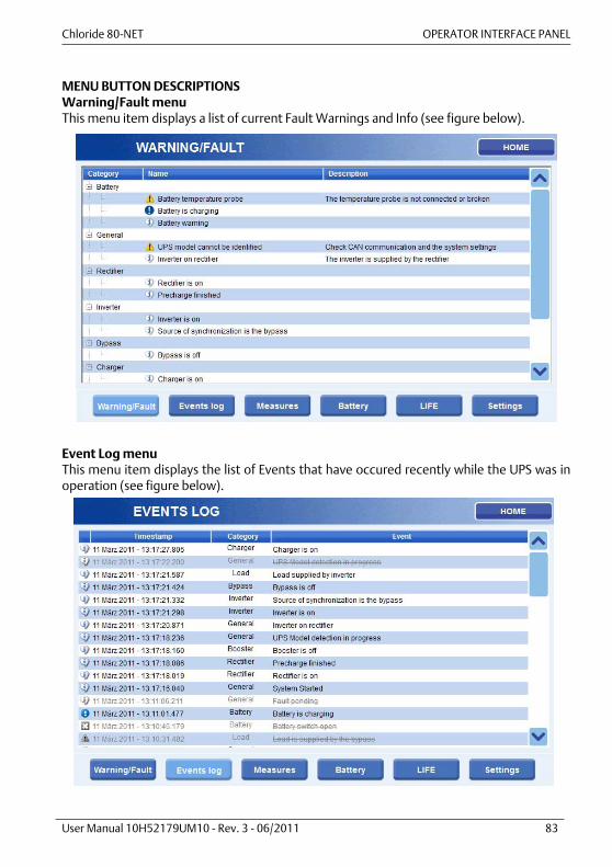
Chloride 80-NET OPERATOR INTERFACE PANEL
User Manual 10H52179UM10 - Rev. 3 - 06/2011 83
MENU BUTTON DESCRIPTIONSWarning/Fault menuThis menu item displays a list of current Fault Warnings and Info (see figure below).
Event Log menuThis menu item displays the list of Events that have occured recently while the UPS was inoperation (see figure below).
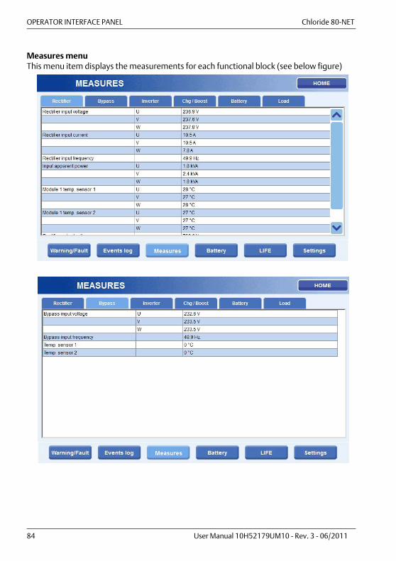
OPERATOR INTERFACE PANEL Chloride 80-NET
84 User Manual 10H52179UM10 - Rev. 3 - 06/2011
Measures menuThis menu item displays the measurements for each functional block (see below figure)
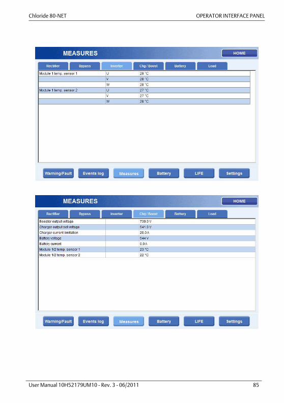
Chloride 80-NET OPERATOR INTERFACE PANEL
User Manual 10H52179UM10 - Rev. 3 - 06/2011 85

OPERATOR INTERFACE PANEL Chloride 80-NET
86 User Manual 10H52179UM10 - Rev. 3 - 06/2011

Chloride 80-NET OPERATOR INTERFACE PANEL
User Manual 10H52179UM10 - Rev. 3 - 06/2011 87
Battery menuThis menu manages the status of the battery (see below figure).
1. Battery Status: 1.1 Battery Status. Specify whether battery is charging or not1.2 Charger Status. Specify Battery Charger status1.3 Battery Test Status. Specify details of the last battery test executed1.4 Automatic Battery Test Status. Specify details related to Automatic battery test
2. Battery Test: The following commands can be set using this page2.1 Enable automatic battery test. Using this command, the Automatic Battery test is
enabled using the existing parameter configuration. These parameters can bemodified only by PPvis
2.2 Configure and manage Manual Battery test. Features:2.2.1 Test duration and Min Voltage can be modified using the + and - button2.2.2 Start battery using dedicated command button (Start Battery Test)2.2.3 Test duration can be monitored on a dedicated progress bar (Battery test
progress bar )2.2.4 While the test is running, it can be aborted with a dedicated Stop command
button (Stop Battery Test)2.2.5 Battery test status provides immediate information about test status
3. Battery measures: This section monitors variables applicable to the battery.
1 2 3
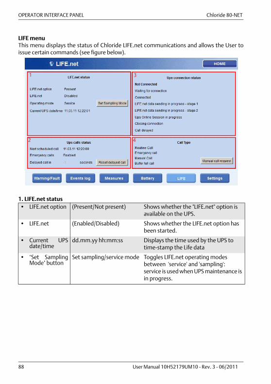
OPERATOR INTERFACE PANEL Chloride 80-NET
88 User Manual 10H52179UM10 - Rev. 3 - 06/2011
LIFE menuThis menu displays the status of Chloride LIFE.net communications and allows the User toissue certain commands (see figure below).
1. LIFE.net status• LIFE.net option (Present/Not present) Shows whether the "LIFE.net" option is
available on the UPS.
• LIFE.net (Enabled/Disabled) Shows whether the LIFE.net option has been started.
• Current UPSdate/time
dd.mm.yy hh:mm:ss Displays the time used by the UPS to time-stamp the Life data
• ‘Set SamplingMode’ button
Set sampling/service mode Toggles LIFE.net operating modes between 'service' and 'sampling': service is used when UPS maintenance is in progress.
1 3
2 4
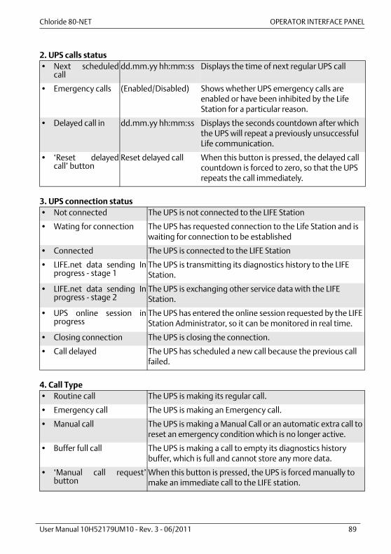
Chloride 80-NET OPERATOR INTERFACE PANEL
User Manual 10H52179UM10 - Rev. 3 - 06/2011 89
2. UPS calls status
3. UPS connection status
4. Call Type
• Next scheduledcall
dd.mm.yy hh:mm:ss Displays the time of next regular UPS call
• Emergency calls (Enabled/Disabled) Shows whether UPS emergency calls are enabled or have been inhibited by the Life Station for a particular reason.
• Delayed call in dd.mm.yy hh:mm:ss Displays the seconds countdown after which the UPS will repeat a previously unsuccessful Life communication.
• ‘Reset delayedcall’ button
Reset delayed call When this button is pressed, the delayed call countdown is forced to zero, so that the UPS repeats the call immediately.
• Not connected The UPS is not connected to the LIFE Station
• Wating for connection The UPS has requested connection to the Life Station and is waiting for connection to be established
• Connected The UPS is connected to the LIFE Station
• LIFE.net data sending Inprogress - stage 1
The UPS is transmitting its diagnostics history to the LIFE Station.
• LIFE.net data sending Inprogress - stage 2
The UPS is exchanging other service data with the LIFE Station.
• UPS online session inprogress
The UPS has entered the online session requested by the LIFE Station Administrator, so it can be monitored in real time.
• Closing connection The UPS is closing the connection.
• Call delayed The UPS has scheduled a new call because the previous call failed.
• Routine call The UPS is making its regular call.
• Emergency call The UPS is making an Emergency call.
• Manual call The UPS is making a Manual Call or an automatic extra call to reset an emergency condition which is no longer active.
• Buffer full call The UPS is making a call to empty its diagnostics history buffer, which is full and cannot store any more data.
• ‘Manual call request’button
When this button is pressed, the UPS is forced manually to make an immediate call to the LIFE station.
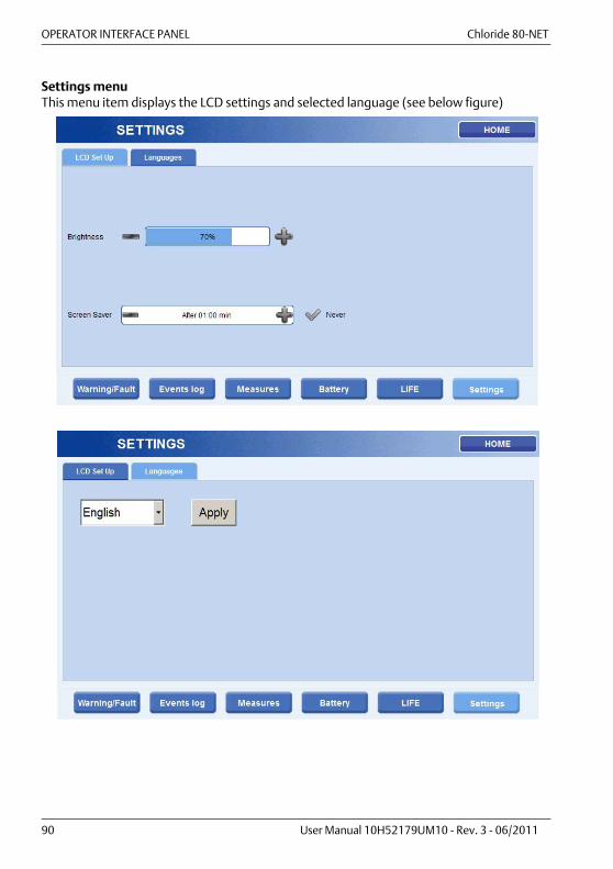
OPERATOR INTERFACE PANEL Chloride 80-NET
90 User Manual 10H52179UM10 - Rev. 3 - 06/2011
Settings menuThis menu item displays the LCD settings and selected language (see below figure)

Chloride 80-NET OPERATOR INTERFACE PANEL
User Manual 10H52179UM10 - Rev. 3 - 06/2011 91
8. Animated One Line Mimic: this area displays all the functional blocks in the UPS. Touchany icon to obtain detailed information about the corresponding functional block. The colorof the block identifies its functional status:
• normal conditions • warning conditions • fault conditions
ANIMATED ONE LINE MIMIC MENU DESCRIPTIONBy clicking on a block (Rectifier, Inverter, ...), the relative page providing detailedinformation will be displayed.
Rectifier Functional blockThis page displays detailed information about the current status of the Rectifier.
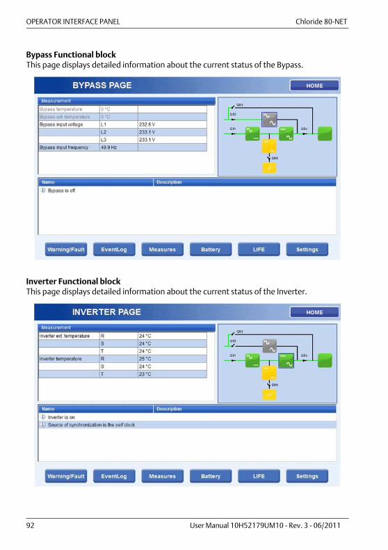
OPERATOR INTERFACE PANEL Chloride 80-NET
92 User Manual 10H52179UM10 - Rev. 3 - 06/2011
Bypass Functional blockThis page displays detailed information about the current status of the Bypass.
Inverter Functional blockThis page displays detailed information about the current status of the Inverter.

Chloride 80-NET OPERATOR INTERFACE PANEL
User Manual 10H52179UM10 - Rev. 3 - 06/2011 93
Booster Functional blockThis page displays detailed information about the current status of the Booster.
Battery Functional blockThis page displays detailed information about the current status of the Battery.

OPERATOR INTERFACE PANEL Chloride 80-NET
94 User Manual 10H52179UM10 - Rev. 3 - 06/2011
Load Functional blockThis page displays detailed information about the current status of the Load.
9. About button: this button displays the Type and Size of the unit. When this area istouched, you will obtain Serial Number, FW details and IP and MAC addresses.This page displays detailed information about the UPS S/, size and model, FW revision andsystem time.
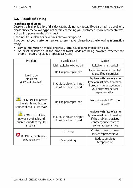
Chloride 80-NET OPERATOR INTERFACE PANEL
User Manual 10H52179UM10 - Rev. 3 - 06/2011 95
6.2.1. Troubleshooting
Rectification of Errors Despite the high reliability of this device, problems may occur. If you are having a problem,please check the following points before contacting your customer service representative:Is there line power on the UPS input?Is the input fuse blown or have circuit breakers tripped?If you contact your customer service representative, please have the following informationready:• Device information = model, order no., series no. as per identification plate.• An exact description of the problem (what loads are being powered, whether the
problem occurs regularly or sporadically, etc.)
Problem Possible cause Action
No displayNo alarm
(UPS switched off)
Main switch switched off Switch on main switch
No line power presentHave line power inspected
by qualified electrician
Input fuse blown or input circuit breaker tripped
Replace with fuse of same type or reset circuit breaker. If problem persists, contact
your customer service representative.
ICON ON, line power not available and buzzer
sounds at regular intervals
No line power presentNormal mode. UPS from
battery
ICON ON, but line power is available and
buzzer sounds at regular intervals
Input fuse blown or input circuit breaker tripped
Replace with fuse of same type or reset circuit breaker.
If the problem persists, contact your customer service representative.
ICON ON, continuous acoustic alarm
UPS errorContact your customer service representative
OverheatingReduce ambient
temperature

OPERATOR INTERFACE PANEL Chloride 80-NET
96 User Manual 10H52179UM10 - Rev. 3 - 06/2011
Backup time less than that specified
External cabinet BATTERY FUSE "OPEN".
Move the fuse switch to the "ON" position.
Batteries are not completely charged
Charge batteries, and test backup time. If problem
persists, contact your customer service rep.
Batteries are defective Contact customer service
Charging device is defectiveCheck battery charge status
on the LCD. Contact customer service.
Problem Possible cause Action

Chloride 80-NET Maintenance
User Manual 10H52179UM10 - Rev. 3 - 06/2011 97
7. MAINTENANCE
7.1. Maintenance intervalsChloride recommends that regular maintenance checks be carried out on-site by anauthorized customer service. The UPS informs the user when the normal service life of a fanhas ended. A replacement fan is recommended.
7.2. Disposal of batteriesWhen the useful life of the batteries has ended, they must be replaced by your CustomerService representative. Exhausted accumulator batteries are classified as “harmful toxicwaste” that must be disposed of in the EU by a certified disposal specialist . Outside the EU,they must be disposed of in accordance with the applicable regulations for the givencountry. The Customer service centre is fully equipped to deal with such batteries inaccordance with regulations and with full respect for the environment.The typical useful life of the battery is 3 to 5 years at 25° C ambient temperature. However,useful life also depends on the frequency and duration of line power failures.
7.3. Service addressesOnsite service is available worldwide. Service telephone and fax numbers can be found onthe last page of this manual.
7.4. Decommisioning
7.4.1. Taking out of service
N.B. Switch to service Bypass• Switch the UPS to Maintenance Bypass operation (see para 5.7.3. on page 61)N.B. Disconnect the batteries• Open the battery isolator or battery switch if other external batteries are used.• Before continuing work, measure the voltage on the battery terminals and on the line
power input, and wait until these have dropped to 0 V; or wait at least 5 min. Failure todo so may cause severe electrical shock and possibly death.
The UPS is now in the maintenance Bypass operating mode. The only voltage present is atthe line power and load terminals. Qualified personnel may now carry out maintenance workwhile taking the corresponding safety measures.
N.B. Disconnect line powerIf the loads no longer need power, you may open the external line power separation devicefor the UPS.

Maintenance Chloride 80-NET
98 User Manual 10H52179UM10 - Rev. 3 - 06/2011

Chloride 80-NET PARALLEL CONFIGURATION
User Manual 10H52179UM10 - Rev. 3 - 06/2011 99
8. PARALLEL CONFIGURATION
Up to 8 Chloride 80-NET units can be connected in parallel to increase power capacity andthus to provide more secure power to the load (redundancy).The modules in parallel exchange information via a 15-wire shielded cable.The total load current is shared between the modules.For optimum performance of the parallel system and proper current sharing, especially inthe Bypass mode, make sure that the series impedance of the modules in parallel is thesame.The cross section and length of the power cables used to connect the inputs of each UPSmodule must be the same. The same applies to the output cables and the battery cables, ifthe modules are connected to the same DC source.Differences of 20% are allowed for power cable lengths of up to 20 m. For larger distances,cable lengths may not vary by more than 10%.
8.1. Placement into servicePlacement into service of multiple-block systems must be carried out by appropriatelytrained technicians.
8.2. System configurationsFig. 42 and Fig. 43 illustrate the schematic diagram of a multiple-block system with ServiceBypass Switch (SBS) in various multiple-block systems - contact Chloride Technical Supportfor more information. The SBS shown in the diagrams may be installed in Chloride 80-NETparallel systems where standard, 400 V units are installed.
8.3. Communication between UPS blocksUPS units exchange information through the connector cable (15 pin connector). Fig. 44displays the loop circuit, which is electronically monitored. The communication cables areshielded and must be run separately and away from the power cables. The total length ofthese cables should not exceed 19m.

PARALLEL CONFIGURATION Chloride 80-NET
100 User Manual 10H52179UM10 - Rev. 3 - 06/2011
8.4. Parallel switching proceduresProcedures refer to para 5.3. on page 55.
8.4.1. Procedure 1: UPS TURN-ON PROCEDUREStarting with each UPS completely deenergized, this procedure explains how to switch onUPS units and set them to Normal Operation Mode. On each UPS, perform the followingprocedure:
8.4.2. Procedure 2: UPS TURN-OFF PROCEDUREStarting with each UPS in Normal Mode, this procedure explains how to switch off the UPSunits. When this procedure is followed completely, the output voltage will be completelyturned off and any load(s) connected to the UPS output will be shut down. On each UPS,perform the following procedure:
Step Action Status
1 Switch QS1 to the ON position Rectifier start up
2 Switch QS2 to the ON position (wait for Static Bypass Switch to switch on)
Static Bypass Switch ON and fans ON
3 Close external battery switches, then set switch QS9 to the ON position
4 Switch QS4 to the ON positionIMPORTANT: when switch QS4 is closed, the output of the UPS and all the loads connected to it will be energized.
System in Bypass Mode - Output voltage present
When the above steps have been completed for all the UPS units in the parallel system:
5 On the 60-200 kVA version, press the “Start Inverter” button on the monitor panel of each UPS (for approx. 5 seconds) until all the inverters are ON. On the 300-500 kVA version, touch the “Start Inverter” icon. At this point, the Inverters synchronize and take over the Load
Normal Mode (On Line)
Step Action Status
1 On the 60-200 kVA version, press the “Stop Inverter” button on the monitor panel of each UPS (for approx. 5 seconds) until all the inverters are OFF. On the 300-500 kVA version, touch the “Stop Inverter” icon. At this point, the Load is supplied by the Bypass
System in Bypass Mode
2 Switch QS9 to the OFF position3 Switch QS4 to the OFF position Load not
supplied4 Switch QS2 to the OFF position5 Switch QS1 to the OFF position
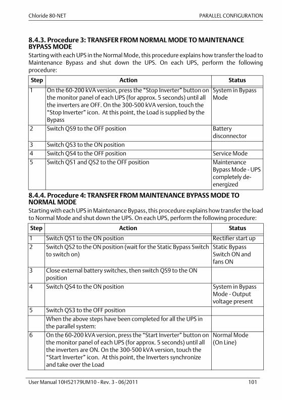
Chloride 80-NET PARALLEL CONFIGURATION
User Manual 10H52179UM10 - Rev. 3 - 06/2011 101
8.4.3. Procedure 3: TRANSFER FROM NORMAL MODE TO MAINTENANCE BYPASS MODEStarting with each UPS in the Normal Mode, this procedure explains how transfer the load toMaintenance Bypass and shut down the UPS. On each UPS, perform the followingprocedure:
8.4.4. Procedure 4: TRANSFER FROM MAINTENANCE BYPASS MODE TO NORMAL MODEStarting with each UPS in Maintenance Bypass, this procedure explains how transfer the loadto Normal Mode and shut down the UPS. On each UPS, perform the following procedure:
Step Action Status
1 On the 60-200 kVA version, press the “Stop Inverter” button on the monitor panel of each UPS (for approx. 5 seconds) until all the inverters are OFF. On the 300-500 kVA version, touch the “Stop Inverter” icon. At this point, the Load is supplied by the Bypass
System in Bypass Mode
2 Switch QS9 to the OFF position Battery disconnector
3 Switch QS3 to the ON position4 Switch QS4 to the OFF position Service Mode5 Switch QS1 and QS2 to the OFF position Maintenance
Bypass Mode - UPS completely de-energized
Step Action Status
1 Switch QS1 to the ON position Rectifier start up2 Switch QS2 to the ON position (wait for the Static Bypass Switch
to switch on)Static Bypass Switch ON and fans ON
3 Close external battery switches, then switch QS9 to the ON position
4 Switch QS4 to the ON position System in Bypass Mode - Output voltage present
5 Switch QS3 to the OFF positionWhen the above steps have been completed for all the UPS in the parallel system:
6 On the 60-200 kVA version, press the “Start Inverter” button on the monitor panel of each UPS (for approx. 5 seconds) until all the inverters are ON. On the 300-500 kVA version, touch the “Start Inverter” icon. At this point, the Inverters synchronize and take over the Load
Normal Mode (On Line)
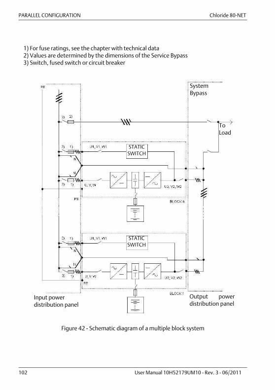
PARALLEL CONFIGURATION Chloride 80-NET
102 User Manual 10H52179UM10 - Rev. 3 - 06/2011
Figure 42 - Schematic diagram of a multiple block system
Output powerdistribution panel
Input power distribution panel
SystemBypass
1) For fuse ratings, see the chapter with technical data2) Values are determined by the dimensions of the Service Bypass3) Switch, fused switch or circuit breaker
ToLoad
STATICSWITCH
STATICSWITCH
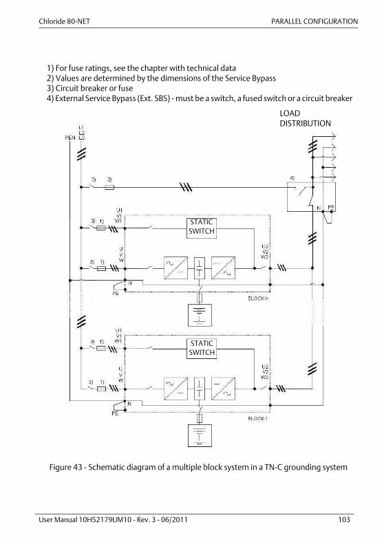
Chloride 80-NET PARALLEL CONFIGURATION
User Manual 10H52179UM10 - Rev. 3 - 06/2011 103
Figure 43 - Schematic diagram of a multiple block system in a TN-C grounding system
1) For fuse ratings, see the chapter with technical data2) Values are determined by the dimensions of the Service Bypass 3) Circuit breaker or fuse4) External Service Bypass (Ext. SBS) - must be a switch, a fused switch or a circuit breaker
LOADDISTRIBUTION
STATICSWITCH
STATICSWITCH

PARALLEL CONFIGURATION Chloride 80-NET
104 User Manual 10H52179UM10 - Rev. 3 - 06/2011
Figure 44 - Loop circuit for parallel UPS (15 pin connector)
1) 15-way Sub-D plug cable
X19/A
X19/B
UPS 41)
UPS 3
UPS 2
UPS 1
X19/A
X19/B
X19/A
X19/B
X19/A
X19/B
1)
1)
1)

Chloride 80-NET Options
User Manual 10H52179UM10 - Rev. 3 - 06/2011 105
9. OPTIONS
Some of the options listed in this section may modify the data on the standard technical datatables (see chap. 10. on page 113). It may not be possible to use certain optionssimultaneously on the same UPS.
9.1. Remote alarm unitA remote alarm panel is available for displaying important individual UPS messages. Thelength of the connection cable must not exceed 300m.
9.2. External battery circuit breakerThis option consists of a fully-rated circuit breaker with an auxiliary contact which allows theUPS to monitor its status via a dedicated input contact. The circuit breaker is housed in awall-mounted box and designed for use with rack-mounted battery systems. The circuitbreaker also protects the power cables connecting the battery to the UPS.
9.3. Top cable entryThis option permits power cables to be routed through the top of the UPS (with ratings from60 to 120 kVA only).
9.4. Dust filtersThis option improves the air inlet protection level from IP20 to IP40 for specific applicationssuch as dusty environments. The filter is housed in the UPS compartment (IP20).
9.5. Empty battery compartmentThese compartments consist of:• Compartment• Disconnecting device• Fuses• Safety panel• Connection terminals• UPS/battery connection cables (for adjacent installation)There are two sizes available:
* including front handle; without handle: 830 mm.
9.6. Empty options compartmentA matching compartment is available for customized applications such as:• Isolation transformers• Input/Output voltage matching transformers• Customized distribution boards
Width (mm) Depth (mm) Height (mm) Net Weight (kg)Type A 820 858* 1780 210Type B 1020 858* 1780 260

Options Chloride 80-NET
106 User Manual 10H52179UM10 - Rev. 3 - 06/2011
One size is available:
* including front handle; without handle: 830 mm.
9.7. Frequency converter applicationChloride 80-NET can be programmed for use as a frequency converter (50Hz in - 60Hz out,or 60Hz in - 50Hz out), with or without a battery connected. In this operating configuration,the data (such as output overload capacity) shown in the standard technical data tables mayvary. Please contact Chloride Technical Support for details.
9.8. MopUPS shutdown and monitoring softwareMopUPS Professional is a software package providing safe system shutdown and powermanagement. With advanced features such as network shutdown, scheduled shutdown andrestart, event messaging, event logging, data logging, real time viewing, UPS diagnosticsand remote access, MopUPS has everything necessary for preserving data and maximizingsystem uptime.The software features:
1 Remote managementSite power and UPS status information can be accessed securely from any computer onyour IP-based network. View event history and voltage logs for trend analysis. View UPSsystem status in real time for situational decision support. Access is based on UserAuthentication with 128bit, MD5 encryption.
2 Remote messagingKeeps you informed anywhere -- fault and recovery messages are sent via SNMP Trap oremail. Body of email will include URL for quick link back to UPS Web page. Many pagersystems will forward email to your wireless pager - so you can be informed anywhere.
3 Safe system shutdownPreserves data integrity and minimizes recovery delays with automated systemshutdown. MopUPS monitors the UPS for power failure, low battery, or other events thatjeopardize computer power -- and initiates controlled system shutdown.
While it is always possible to use a serial connection, it is recommended that a ManageUPSnetwork SNMP Adapter be used for scommunication between MopUPS Professional andChloride 80-NET so that multiple Server Systems can communicate with the UPS viaEthernet.With Chloride 80-NET in redundant parallel configuration, MopUPS P/R Edition monitors allthe connected Chloride 80-NET units simultaneously. It acquires load data, estimatedcapacities, and other measurements from individual modules, and groups them togetheraccording to whether the system is serial or parallel-redundant and whether it is centralizedor parallel-distributed (with or without redundancy). This special edition of MopUPS cananalyse module-specific conditions and report situations that may affect redundancy orpower margin. ManageUPS Net Adapter is required when using MopUPS P/R Edition.For more details, see http://connectivity.chloridepower.com/
Width (mm) Depth (mm) Height (mm) Net Weight (kg)Type B 1020 858* 1780 240

Chloride 80-NET Options
User Manual 10H52179UM10 - Rev. 3 - 06/2011 107
9.9. ManageUPS adapterManageUPS NET Adapter III offers an open approach to network power management bydelivering a complete set of manageability options including: WEB, Telnet, and Out-Of-Bandaccessibility, in addition to the full-featured, embedded SNMP agent. Event messages arealso available as email and SNMP Traps - a truly versatile tool for managing Chloride 80-NETUPS systems in a network environment.The software features:
1 DHCP Network ConfigurationSupports automatic IP settings configuration using the DHCP protocol. The DHCP servermust be located on a network that is routable from the LAN which ManageUPS-II isconnected to.
2 Multiple Network Access MethodsSite power and UPS status information can be accessed securely from any computer onyour network. View UPS system status in real time for situational decision support.Access via Telnet, SNMP, or Web Browser. SNMP Agent conforms to RFC1628 StandardUPS MIB.
3 Network ShutdownManageUPS includes a UPS status server and a network shutdown controller. Use thesefeatures with host shutdown software (RCCMD, MopUPS NSA, MopUPS Professional orMopUPS P/R) to ensure safe shutdown of multiple servers, workstations or PCs in TCP/IPnetwork environments.
4 Event and Data LoggingManageUPS II keeps a log file of UPS events and environment data. On-board log fileviewer lets you filter records for easy analysis.
For details, see http://connectivity.chloridepower.com/

Options Chloride 80-NET
108 User Manual 10H52179UM10 - Rev. 3 - 06/2011
9.10. ConnectivityThe following table gives details of the various combinations of connectivity solutions whichcan be used in association with Chloride 80-NET. Only one of the combinations may be usedat a time; other combinations may be possible. For port numbers, please refer to chap. 4. onpage 45. For further information, please see Chloride Connectivity. The following interfacescan be found on Chloride 80-NET:
Interface Description Input/Output/Serial/CANXS3 Slot available for use with a connectivity
option, typically ManageUPS NET III AdapterSerial
XS6 Slot for the LIFE.net slot modem SerialX3 Standard serial interface RS232 COM
- female -Available, if XS3 slot is empty or MUN III cardis installed
Serial
X6 Standard serial interface RS232 COM forexternal LIFE.net kit (e.g. LIFE.net, GSMmodem) only is XS6 is empty- male -Not available, if a XS6 slot modem is installed
Serial
X9 RJ45 Ethernet interface for service andplacement into service;Interface for PPVis communication
CAN
X19 2x15-pole screw connector for parallel UPSconnection
X20 RJ45 interface for synchronization withexternal signal
XT_A/B 2x16-pole screw connector for input andoutput contacts
Input and Output
XT 1/2 Only pin 1 and 2 of the 4-pole screwconnector is used for> external battery status
Input
XT 3/08 4-pole screw for EPO input and output Input and OutputXT1 External battery temperature sensor
connectionInput
XT2 2-pole screw connector for backfeed outputcontact
Output
XT4 Not used!
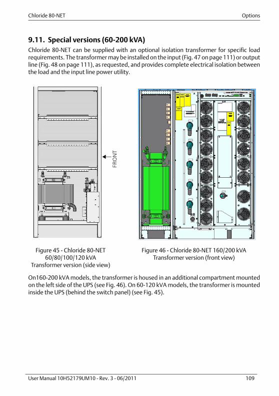
Chloride 80-NET Options
User Manual 10H52179UM10 - Rev. 3 - 06/2011 109
9.11. Special versions (60-200 kVA)Chloride 80-NET can be supplied with an optional isolation transformer for specific loadrequirements. The transformer may be installed on the input (Fig. 47 on page 111) or outputline (Fig. 48 on page 111), as requested, and provides complete electrical isolation betweenthe load and the input line power utility.
On160-200 kVA models, the transformer is housed in an additional compartment mountedon the left side of the UPS (see Fig. 46). On 60-120 kVA models, the transformer is mountedinside the UPS (behind the switch panel) (see Fig. 45).
Figure 45 - Chloride 80-NET60/80/100/120 kVA
Transformer version (side view)
Figure 46 - Chloride 80-NET 160/200 kVA Transformer version (front view)
FRONT
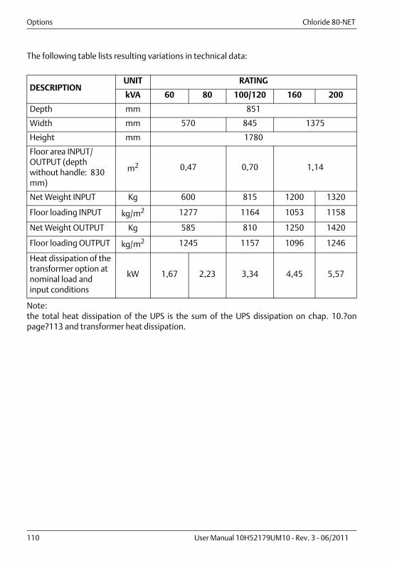
Options Chloride 80-NET
110 User Manual 10H52179UM10 - Rev. 3 - 06/2011
The following table lists resulting variations in technical data:
Note:the total heat dissipation of the UPS is the sum of the UPS dissipation on chap. 10.?onpage?113 and transformer heat dissipation.
DESCRIPTIONUNIT RATING
kVA 60 80 100/120 160 200
Depth mm 851
Width mm 570 845 1375
Height mm 1780
Floor area INPUT/OUTPUT (depth without handle: 830 mm)
m2 0,47 0,70 1,14
Net Weight INPUT Kg 600 815 1200 1320
Floor loading INPUT kg/m2 1277 1164 1053 1158
Net Weight OUTPUT Kg 585 810 1250 1420
Floor loading OUTPUT kg/m2 1245 1157 1096 1246
Heat dissipation of the transformer option at nominal load and input conditions
kW 1,67 2,23 3,34 4,45 5,57
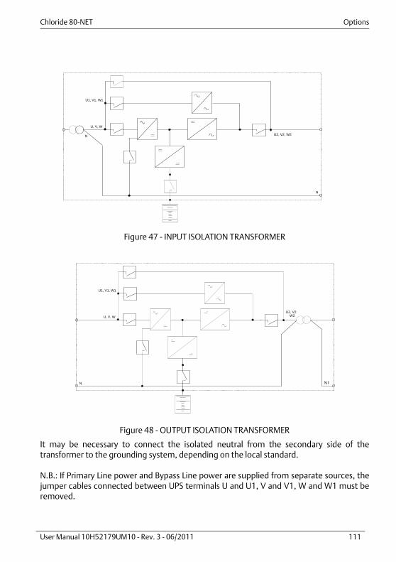
Chloride 80-NET Options
User Manual 10H52179UM10 - Rev. 3 - 06/2011 111
Figure 47 - INPUT ISOLATION TRANSFORMER
Figure 48 - OUTPUT ISOLATION TRANSFORMER
It may be necessary to connect the isolated neutral from the secondary side of thetransformer to the grounding system, depending on the local standard.
N.B.: If Primary Line power and Bypass Line power are supplied from separate sources, thejumper cables connected between UPS terminals U and U1, V and V1, W and W1 must beremoved.
U, V, W
U1, V1, W1
U2, V2, W2
N
N
U, V, W
U1, V1, W1
U2, V2 W2
NN N1

Options Chloride 80-NET
112 User Manual 10H52179UM10 - Rev. 3 - 06/2011

Chloride 80-NET Technical data
User Manual 10H52179UM10 - Rev. 3 - 06/2011 113
10. TECHNICAL DATA
10.1. UPS 60-120 kVAUPS model Chloride 80-NET
Power (kVA) 60 80 100 120
System dataAC/AC efficiency with resistive load, without
recharging current1) 2)
50% load (%)100% load (%)VFD (%)
94,494,598,3
94,594,598,3
94,795
98,3
9595
98,3
Heat dissipation at
maximum output load1)
Float mode (kW)(Btu/h)
3,5 4,7 5,3 6,3
10723 14298 16162 19395
Recharge mode (kW)(Btu/h)
3,7 4,8 5,5 6,6
12458 16544 18856 22570
Digital i/active mode (kW)
1,2 1,6 2,0 2,4
Noise at 1 m as per ISO 3746 (dBA ± 2dBA) 62 65
Protection degree with doors open IP20
Mechanical dimensions:
Height (mm) 1780
Width (mm) 570 845
Depth (mm) 851
Shipping Weight (kg) 320 436
Net Weight (kg) 290 400
Number of cabinets 1
Frame color (RAL scale) 7016
Floor area (depth without handle: 830 mm) (m2) 0,47 0,70
Floor loading (kg/m2) 592 613 570
Cable entry Bottom
Service access Front/Top
Cooling
(m3/h)
Forced ventilation, front air intake, top air outlet
662 918
LocationIndoor
(free from corrosive gases and conductive dust)
TemperatureOperating (°C)3) 0-40
Transport andstorage (°C)
-20 to +70
Max. relative humidity @ 20°C (non condensing)(%) Up to 95
Max. altitude above sea-level without derating (m)Up to 1000 above M.S.L. (at higher altitudes
Chloride 80-NET complies with IEC/EN 62040-3)
Immunity to electrical interference IEC/EN 62040-2
EMC CLASS standard IEC/EN 62040-2 Class C3
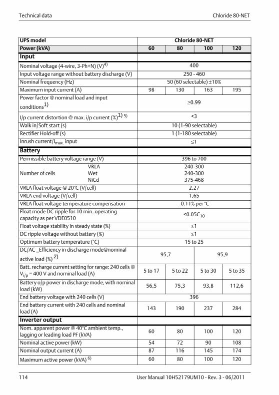
Technical data Chloride 80-NET
114 User Manual 10H52179UM10 - Rev. 3 - 06/2011
Input
Nominal voltage (4-wire, 3-Ph+N) (V)4) 400
Input voltage range without battery discharge (V) 250 - 460
Nominal frequency (Hz) 50 (60 selectable) 10%
Maximum input current (A) 98 130 163 195
Power factor @ nominal load and input
conditions1) 0.99
I/p current distortion @ max. i/p current (%)1) 5) <3
Walk in/Soft start (s) 10 (1-90 selectable)
Rectifier Hold-off (s) 1 (1-180 selectable)
Inrush current/Imax. input 1
BatteryPermissible battery voltage range (V) 396 to 700
Number of cellsVRLAWetNiCd
240-300240-300375-468
VRLA float voltage @ 20°C (V/cell) 2,27
VRLA end voltage (V/cell) 1,65
VRLA float voltage temperature compensation -0.11% per °C
Float mode DC ripple for 10 min. operating capacity as per VDE0510
<0.05C10
Float voltage stability in steady state (%) 1
DC ripple voltage without battery (%) 1
Optimum battery temperature (°C) 15 to 25
DC/AC _Efficiency in discharge mode@nominal
active load (%) 2) 95,7 95,9
Batt. recharge current setting for range: 240 cells @ Vi/p = 400 V and nominal load (A) 5 to 17 5 to 22 5 to 30 5 to 35
Battery o/p power in discharge mode, with nominal load (kW)
56,5 75,3 93,8 112,6
End battery voltage with 240 cells (V) 396
End battery current with 240 cells and nominalload (A)
143 190 237 284
Inverter outputNom. apparent power @ 40°C ambient temp., lagging or leading load PF (kVA)
60 80 100 120
Nominal active power (kW) 54 72 90 108
Nominal output current (A) 87 116 145 174
Maximum active power (kVA) 6) 60 80 100 120
UPS model Chloride 80-NET
Power (kVA) 60 80 100 120
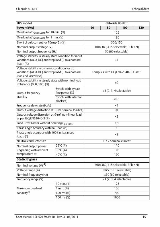
Chloride 80-NET Technical data
User Manual 10H52179UM10 - Rev. 3 - 06/2011 115
Overload at VOUT NOM. for 10 min. (%) 125
Overload at VOUT NOM. for 1 min. (%) 150
Short circuit current for 10ms/<5s (%) 300/150
Nominal output voltage (V) 400 (380/415 selectable; 3Ph + N)
Nominal output frequency (Hz) 50 (60 selectable)
Voltage stability in steady state condition for input variations (AC & DC) and step load (0 to a nominal load) (%)
±1
Voltage stability in dynamic condition for i/p variations (AC & DC) and step load (0 to a nominal load and vice versa)
Complies with IEC/EN 62040-3, Class 1
Voltage stability in steady state with nominal load imbalance (0, 0, 100) (%)
±3
Output frequencystability
Synch. with bypass line power (%)
±1 (2, 3, 4 selectable)
Synch. with internal clock (%)
±0.1
Frequency slew rate (Hz/s) <1
Output voltage distortion at 100% nominal load (%) <1
Output voltage distorsion at @ ref. non-linear load as per IEC/EN62040-3 (%)
<3
Load Crest Factor without derating (Ipk:Irms) 3:1
Phase angle accuracy with bal. loads (°) 1
Phase angle accuracy with 100% unbalancedloads (°)
<3
Neutral conductor size 1.7 x nominal current
Nominal output power upgrading with ambient temperature at:
25°C (%) 110
30°C (%) 105
40°C (%) 100
Static Bypass
Nominal voltage (V) 4) 400 (380/415 selectable, 3Ph + N)
Voltage range (%) 10 (5 to 15 selectable)
Nominal frequency (Hz) ±50 (60 selectable)
Frequency range (%) ±1 (2, 3, 4 selectable)
Maximum overload
capacity7)
10 min. (%) 125
1 min. (%) 150
600 ms (%) 700
100 ms (%) 1000
UPS model Chloride 80-NET
Power (kVA) 60 80 100 120

Technical data Chloride 80-NET
116 User Manual 10H52179UM10 - Rev. 3 - 06/2011
General conditions for the Technical Data table:The data shown are typical and not definable in other ways; furthermore, the data refer to25°C ambient temperature and PF= 1 unless otherwise specified.Not all the data shown apply simultaneously and may be changed without prior notice.Data apply to the standard version, unless otherwise specified. For test conditions andmeasurement tolerances not specified on the table, see the Witness Test Report procedure.
SCR
I2t @ Tvj=125 °C
8.3-10 ms (A2s)80000 125000
ITSM @ Tvj=125 °C10 ms (A)
4000 5000
Inverter fuse ratingI2t @ Tvj=125 °C
8.3-10 ms (A2s)3800 14500
Inverter to Bypass and Bypass to inverter transfer time with inverter synchronized to Bypass (ms)
No break
Default transfer delay time (inverter to Bypass) with inverter not synchronized to Bypass (ms)
<20
1) Nominal input voltage and input frequency;2) For tolerances see IEC/EN 60146-1 or DIN VDE 0558. The data refers to 25°C ambient temperature;3) Recommended average daily ambient temperature 35°C, with a maximum of 40°C for 8 hours, as
required by product standard;4) If a split input configuration is used, the primary input and the Bypass input must have a common
neutral. The neutral conductor may be connected only to the Bypass or to primary line power, but it must be present (Bypass and primary neutrals are connected inside the UPS);
5) With input voltage at nominal value and voltage distortion THD 1%;6) Nominal apparent power loads with PF > 0.9 can be supplied with marginal limitation of
other performance values. Please contact the technical support team for further information;
7) In case of different levels of overload, see the specific overload curve.
NoticeRead and heed the information provided on device labels.
UPS model Chloride 80-NET
Power (kVA) 60 80 100 120
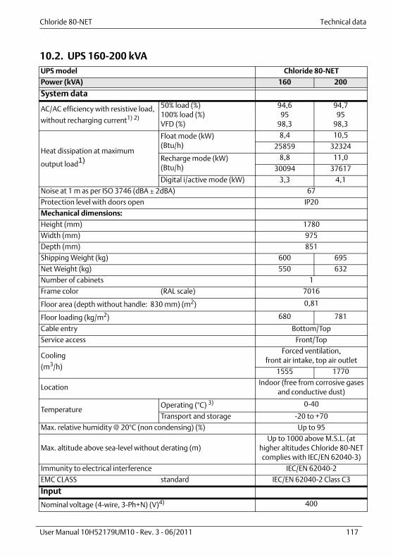
Chloride 80-NET Technical data
User Manual 10H52179UM10 - Rev. 3 - 06/2011 117
10.2. UPS 160-200 kVAUPS model Chloride 80-NET
Power (kVA) 160 200
System data
AC/AC efficiency with resistive load,
without recharging current1) 2)
50% load (%)100% load (%)VFD (%)
94,695
98,3
94,795
98,3
Heat dissipation at maximum
output load1)
Float mode (kW)(Btu/h)
8,4 10,5
25859 32324
Recharge mode (kW)(Btu/h)
8,8 11,0
30094 37617
Digital i/active mode (kW) 3,3 4,1
Noise at 1 m as per ISO 3746 (dBA ± 2dBA) 67
Protection level with doors open IP20
Mechanical dimensions:
Height (mm) 1780
Width (mm) 975
Depth (mm) 851
Shipping Weight (kg) 600 695
Net Weight (kg) 550 632
Number of cabinets 1
Frame color (RAL scale) 7016
Floor area (depth without handle: 830 mm) (m2) 0,81
Floor loading (kg/m2) 680 781
Cable entry Bottom/Top
Service access Front/Top
Cooling
(m3/h)
Forced ventilation,front air intake, top air outlet
1555 1770
Location Indoor (free from corrosive gases
and conductive dust)
TemperatureOperating (°C) 3) 0-40
Transport and storage -20 to +70
Max. relative humidity @ 20°C (non condensing) (%) Up to 95
Max. altitude above sea-level without derating (m)Up to 1000 above M.S.L. (at
higher altitudes Chloride 80-NET complies with IEC/EN 62040-3)
Immunity to electrical interference IEC/EN 62040-2
EMC CLASS standard IEC/EN 62040-2 Class C3
Input
Nominal voltage (4-wire, 3-Ph+N) (V)4) 400
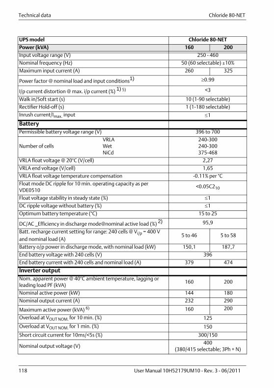
Technical data Chloride 80-NET
118 User Manual 10H52179UM10 - Rev. 3 - 06/2011
Input voltage range (V) 250 - 460
Nominal frequency (Hz) 50 (60 selectable) ±10%
Maximum input current (A) 260 325
Power factor @ nominal load and input conditions1) 0.99
I/p current distortion @ max. i/p current (%) 1) 5) <3
Walk in/Soft start (s) 10 (1-90 selectable)
Rectifier Hold-off (s) 1 (1-180 selectable)
Inrush current/Imax. input 1
BatteryPermissible battery voltage range (V) 396 to 700
Number of cellsVRLAWetNiCd
240-300240-300375-468
VRLA float voltage @ 20°C (V/cell) 2,27
VRLA end voltage (V/cell) 1,65
VRLA float voltage temperature compensation -0.11% per °C
Float mode DC ripple for 10 min. operating capacity as per VDE0510
<0.05C210
Float voltage stability in steady state (%) 1
DC ripple voltage without battery (%) 1
Optimum battery temperature (°C) 15 to 25
DC/AC _Efficiency in discharge mode@nominal active load (%) 2) 95,9
Batt. recharge current setting for range: 240 cells @ Vi/p = 400 V and nominal load (A)
5 to 46 5 to 58
Battery o/p power in discharge mode, with nominal load (kW) 150,1 187,7
End battery voltage with 240 cells (V) 396
End battery current with 240 cells and nominal load (A) 379 474
Inverter outputNom. apparent power @ 40°C ambient temperature, lagging or leading load PF (kVA)
160 200
Nominal active power (kW) 144 180
Nominal output current (A) 232 290
Maximum active power (kVA) 6) 160 200
Overload at VOUT NOM. for 10 min. (%) 125
Overload at VOUT NOM. for 1 min. (%) 150
Short circuit current for 10ms/<5s (%) 300/150
Nominal output voltage (V)400
(380/415 selectable; 3Ph + N)
UPS model Chloride 80-NET
Power (kVA) 160 200

Chloride 80-NET Technical data
User Manual 10H52179UM10 - Rev. 3 - 06/2011 119
Nominal output frequency (Hz) 50 (60 selectable)
Voltage stability in steady state condition for input variations (AC & DC) and step load (0 to 100%) (%)
±1
Voltage stability in dynamic condition for i/p variations (AC & DC) and step load (0 to 100% and vice versa)
Complies with IEC/EN 62040-3, Class 1
Voltage stability in steady state with 100% load imbalance (0, 0, 100) (%)
±3
Output frequency stabilitySynch. with Bypass line power (%)
±1 (2, 3, 4 selectable)
Synch. with internal clock (%) ±0.1
Frequency slew rate (Hz/s) <1
Output voltage distortion at 100% nominal load (%) <1
Output voltage distorsion at @ ref. non-linear load as per IEC/EN62040-3 (%)
<3
Load Crest Factor without derating (Ipk:Irms) 3:1
Phase angle accuracy with bal. loads (°) 1
Phase angle accuracy with 100% unbalanced loads (°) <3
Neutral conductor size 1.7 x nominal current
Nominal output power upgrading with ambient temperature at:
25°C (%) 110
30°C (%) 105
40°C (%) 100
Static Bypass
Nominal voltage (V) 4) 400(380/415 selectable, 3Ph + N)
Voltage range (%) 10 (5 to 15 selectable)
Nominal frequency (Hz) ±50 (60 selectable)
Frequency range (%) ±1 (2, 3, 4 selectable)
Maximum overload capacity 7)
10 min. (%) 125
1 min. (%) 150
600 ms (%) 700
100 ms (%) 1000
SCR
I2t @ Tvj=125 °C; 8.3-10 ms
(A2s)320000
ITSM @ Tvj=125 °C; 10 ms (A) 8000
Inverter fuse ratingI2t @ Tvj=125 °C; 8.3-10 ms
(A2s)44000 67000
Inverter to Bypass and Bypass to inverter transfer time with inverter synchronized to Bypass (ms)
No break
UPS model Chloride 80-NET
Power (kVA) 160 200

Technical data Chloride 80-NET
120 User Manual 10H52179UM10 - Rev. 3 - 06/2011
General conditions for the Technical Data table:The data shown are typical and not definable in other ways; furthermore, the data refer to25°C ambient temperature and PF= 1 unless otherwise specified.Not all the data shown apply simultaneously and may be changed without prior notice.Data apply to the standard version, unless otherwise specified. For test conditions andmeasurement tolerances not specified on the table, see the Witness Test Report procedure.
Default transfer delay time (inverter to Bypass) with inverter not synchronized to Bypass (ms)
<20
1) Nominal input voltage and input frequency;2) For tolerances see IEC/EN 60146-1 or DIN VDE 0558. The data refers to 25°C ambient temperature;3) Recommended average daily ambient temperature 35°C, with a maximum of 40°C for 8 hours, as
required by product standard;4) If a split input configuration is used, the primary input and the Bypass input must have a common
neutral. The neutral conductor may be connected only to the Bypass or to primary line power, but it must be present (Bypass and primary neutrals are connected inside the UPS);
5) With input voltage at nominal value and voltage distortion THD 1%;6) Nominal apparent power loads with PF > 0.9 can be supplied with marginal limitation of other
performance values. Please contact the technical support team for further information;7) In case of different levels of overload, see the specific overload curve.
NoticeRead and heed to the information provided on the device labels.
UPS model Chloride 80-NET
Power (kVA) 160 200

Chloride 80-NET Technical data
User Manual 10H52179UM10 - Rev. 3 - 06/2011 121
10.3. UPS 300-500 kVAUPS model Chloride 80-NET
Power (kVA) 300 400 500
System dataAC/AC efficiency with resistive load, without
recharging current1) 2)
50% load (%)100% load (%)VFD (%)
94,695
98,3
94,795
98,3
9595
98,3
Heat dissipation at
maximum output load1)
Float mode (kW)(Btu/h)
15,8 21,1 26,3
48486 64648 80811
Recharge mode (kW)(Btu/h)
16,5 21,9 27,4
56274 74669 93336
Digital i/active mode (kW)
6,1 8,2 10,2
Noise at 1 m as per ISO 3746 (dBA ± 2dBA) 70 71 72
Protection degree with doors open IP20
Mechanical dimensions:
Height (mm) 1800
Width (mm) 1675 1900
Depth (mm) 851
Shipping Weight (kg) 1115 1285 1550
Net Weight (kg) 1035 1190 1430
Number of cabinets 1
Frame color (RAL scale) 7016
Floor area (depth without handle: 830 mm) (m2) 1,39 1,58
Floor loading (kg/m2) 762 878 907
Cable entry Bottom/Top
Service access Front/Top
Cooling
(m3/h)
Forced ventilation, front air intake, top air outlet
2916 3401 3822
LocationIndoor
(free from corrosive gases and conductive dust)
TemperatureOperating (°C) 3) 0-40
Transport andstorage (°C)
-20 to +70
Max. relative humidity @ 20°C (non condensing) (%) Up to 95
Max. altitude above sea-level without derating (m)Up to 1000 above M.S.L. (at higher altitudes
Chloride 80-NET complies with IEC/EN 62040-3)
Immunity to electrical interference IEC/EN 62040-2
EMC CLASS standard IEC/EN 62040-2 Class C3
Input
Nominal voltage (4-wire, 3-Ph+N) (V)4) 400
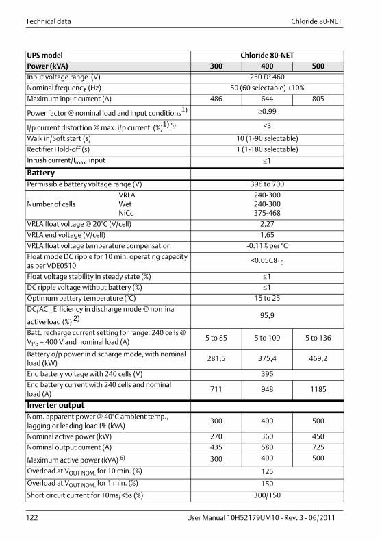
Technical data Chloride 80-NET
122 User Manual 10H52179UM10 - Rev. 3 - 06/2011
Input voltage range (V) 250 в 460
Nominal frequency (Hz) 50 (60 selectable) ±10%
Maximum input current (A) 486 644 805
Power factor @ nominal load and input conditions1) 0.99
I/p current distortion @ max. i/p current (%)1) 5) <3
Walk in/Soft start (s) 10 (1-90 selectable)
Rectifier Hold-off (s) 1 (1-180 selectable)
Inrush current/Imax. input 1
BatteryPermissible battery voltage range (V) 396 to 700
Number of cellsVRLAWetNiCd
240-300240-300375-468
VRLA float voltage @ 20°C (V/cell) 2,27
VRLA end voltage (V/cell) 1,65
VRLA float voltage temperature compensation -0.11% per °C
Float mode DC ripple for 10 min. operating capacity as per VDE0510
<0.05C810
Float voltage stability in steady state (%) 1
DC ripple voltage without battery (%) 1
Optimum battery temperature (°C) 15 to 25
DC/AC _Efficiency in discharge mode @ nominal
active load (%) 2) 95,9
Batt. recharge current setting for range: 240 cells @ Vi/p = 400 V and nominal load (A) 5 to 85 5 to 109 5 to 136
Battery o/p power in discharge mode, with nominal load (kW)
281,5 375,4 469,2
End battery voltage with 240 cells (V) 396
End battery current with 240 cells and nominalload (A)
711 948 1185
Inverter outputNom. apparent power @ 40°C ambient temp., lagging or leading load PF (kVA)
300 400 500
Nominal active power (kW) 270 360 450
Nominal output current (A) 435 580 725
Maximum active power (kVA) 6) 300 400 500
Overload at VOUT NOM. for 10 min. (%) 125
Overload at VOUT NOM. for 1 min. (%) 150
Short circuit current for 10ms/<5s (%) 300/150
UPS model Chloride 80-NET
Power (kVA) 300 400 500

Chloride 80-NET Technical data
User Manual 10H52179UM10 - Rev. 3 - 06/2011 123
Nominal output voltage (V) 400 (380/415 selectable; 3Ph + N)
Nominal output frequency (Hz) 50 (60 selectable)
Voltage stability in steady state condition for input variations (AC & DC) and step load (0 to a nominal load) (%)
±1
Voltage stability in dynamic condition for i/p variations (AC & DC) and step load (0 to a nominal load and vice versa)
Complies with IEC/EN 62040-3, Class 1
Voltage stability in steady state with nominal load imbalance (0, 0, 100) (%)
±3
Output frequencystability
Synch. with Bypass line power (%)
±1 (2, 3, 4 selectable)
Synch. with internal clock (%)
±0.1
Frequency slew rate (Hz/s) <1
Output voltage distortion at 100% nominal load (%) <1
Output voltage distorsion at @ ref. non-linear load as per IEC/EN62040-3 (%)
<3
Load Crest Factor without derating (Ipk:Irms) 3:1
Phase angle accuracy with bal. loads (°) 1
Phase angle accuracy with 100% unbalanced loads(°) <3
Neutral conductor size 1.5 x nominal current
Nominal output power upgrading with ambient temperature at:
25°C (%) 110
30°C (%) 105
40°C (%) 100
Static Bypass
Nominal voltage (V)4) 400 (380/415 selectable, 3Ph + N)
Voltage range (%) 10 (5 to 15 selectable)
Nominal frequency (Hz) ±50 (60 selectable)
Frequency range (%) ±1 (2, 3, 4 selectable)
Maximum overload
capacity7)
10 min. (%) 125
1 min. (%) 150
600 ms (%) 700
100 ms (%) 1000
SCR
I2t @ Tvj=125 °C
8.3-10 ms (A2s)320000 1201250
ITSM @ Tvj=125 °C10 ms (A)
8000 15500
UPS model Chloride 80-NET
Power (kVA) 300 400 500

Technical data Chloride 80-NET
124 User Manual 10H52179UM10 - Rev. 3 - 06/2011
General conditions for the Technical Data table:The data shown are typical and not definable in other ways; furthermore, the data refer to25°C ambient temperature and PF= 1 unless otherwise specified.Not all the data shown apply simultaneously and may be changed without prior notice.Data apply to the standard version, unless otherwise specified. For test conditions andmeasurement tolerances not specified on the table, see the Witness Test Report procedure.
Inverter fuse ratingI2t @ Tvj=125 °C
8.3-10 ms (A2s)176000 268000
Inverter to Bypass and Bypass to inverter transfer time with inverter synchronized to Bypass (ms)
No break
Default transfer delay time (inverter to Bypass) with inverter not synchronized to Bypass (ms)
<20
1) Nominal input voltage and input frequency;2) For tolerances see IEC/EN 60146-1 or DIN VDE 0558. The data refers to 25°C ambient temperature;3) Recommended average daily ambient temperature 35°C, with a maximum of 40°C for 8 hours, as
required by product standard;4) If a split input configuration is used, the primary input and the Bypass input must have a common
neutral. The neutral conductor may be connected only to the Bypass or to primary line power, but it must be present (Bypass and primary neutrals are connected inside the UPS);
5) With input voltage at nominal value and voltage distortion THD 1%;6) Nominal apparent power loads with PF > 0.9 can be supplied with marginal limitation of other
performance values. Please contact the technical support team for further information;7) In case of different levels of overload, see the specific overload curve.
NoticeRead and heed the information provided on device labels.
UPS model Chloride 80-NET
Power (kVA) 300 400 500

Ensuring The High AvailabilityOf Mission-Critical Data And Applications.
Locations
Emerson Network Power - EMEAVia Leonardo Da Vinci 16/18
Zona Industriale Tognana35028 Piove di Sacco (PD) Italy
Tel: +39 049 9719 111Fax: +39 049 5841 257
Chloride - World Headquarters Via Fornace, 30
40023 Castel Guelfo (BO) ItalyTel: +39 0542 632 111Fax: +39 0542 632 120
United States1050 Dearborn Drive
P.O. Box 29186Columbus, OH 43229
Tel: +1 614 8880246
Asia7/F, Dah Sing Financial Centre
108 Gloucester Road, WanchaiHong Kong
Tel: +852 2572220Fax: +852 28029250
Emerson Network PowerThe global leader in enabling Business-Critical Continuity™ EmersonNetworkPower.com
AC Power
Connectivity
DC Power
Embedded Computing
Embedded Power
Infrastructure Management & Monitoring
Outside Plant
Power Switching & Controls
Precision Cooling
Racks & Integrated Cabinets
Services
Surge Protection
Emerson, Business-Critical Continuity and Emerson Network Power are trademarks of Emerson Electric Co. or one of its affiliated companies. ©2011 Emerson Electric Co.