christian ohler, abb switzerland corporate research ... · reactive power is the power flowing into...
TRANSCRIPT
© ABB GroupJuly 20, 2014 | Slide 1
Physical Aspects of Power SystemsControl
Christian Ohler, ABB Switzerland Corporate Research

Purpose of this PresentationDescribe how power systems are controlled
§ (1) Fundamentals: Power system components, active andreactive power
§ (2) Frequency and voltage control
§ (3) Outlook: Impact of renewables?
§ Focus is on the interaction of the components – the systemaspect: why is the power system stable?
© ABB Switzerland Ltd, Corporate ResearchJuly 20, 2014 | Slide 2

Fundamentals: Power System Components,Active and Reactive Power
(1)
© ABB Switzerland Ltd, Corporate ResearchJuly 20, 2014 | Slide 3

Power systems are made from four main components:Overhead lines, transformers, generators, breakers
© ABB Switzerland Ltd, Corporate ResearchJuly 20, 2014 | Slide 4
High voltage overheadlines enable longdistance powertransmission with lowlosses
Transformers allow foradequate voltage
levels for generation,transmission,
distribution, andconsumption
Synchronousgenerators control realpower and reactivepower
Circuit breakers caninterrupt short circuits
and disconnect gridsegments with a fault

Three symmetric phases provide steady power fromalternating current and do not need return conductors
© ABB Switzerland Ltd, Corporate ResearchJuly 20, 2014 | Slide 5
V2~
V1~
V3~
I1à
I2à
I1+I2+I3 = 0N
Current II1 I2 I3
120°I1
I2
I3
Phasor representation
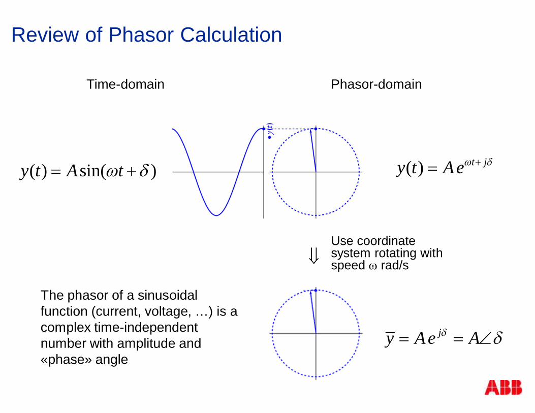
Review of Phasor Calculation
Time-domain Phasor-domain
( ) t jy t Aew d+=( ) sin( )y t A tw d= +
Use coordinatesystem rotating withspeed w rad/sß
jy Ae Ad d= = Ð
The phasor of a sinusoidalfunction (current, voltage, …) is acomplex time-independentnumber with amplitude and«phase» angle
Why bother about active and reactive power?
§ The balance of active power controls the frequency of thegrid
§ The balance of mainly the reactive power controls thevoltage at every point of the grid
© ABB Switzerland Ltd, Corporate ResearchJuly 20, 2014 | Slide 7

Definition of Active and Reactive Power
© ABB Switzerland Ltd, Corporate ResearchJuly 20, 2014 | Slide 8
0
0
§ For each single phase there isthe instaneous power
§ p(t) = v(t) * i(t)
§ Active (real) powerPactive(t) = P*(1-cos(2wt)) where
P = Veff*Ieff*cos(f)
Veff = Vmax /√2 etc. , =
èOscillates around P, is nevernegative
§ Reactive powerPreactive(t) = Q* sin(2wt) where
Q = Veff*Ieff*sin(f)
èOscillates around zero
v(t)i(t)
p(t)
p(t)p_active(t)
p_reactive(t)
f
T

Reactive power is the power flowing into and out of themagnetic field around the conductors
§ Three phases
§ The sum of active power is timeindependent (doesn’t oscillate)
§ The sum of reactive power is zero, but theredistribution of the magnetic field is theconsequence of the oscillating reactivepower in each phase
è Reactive power flow can not be neglected!
§ Sign convention: inductors (lines,transformers, induction motors) consumereactive power, capacitors generate reactivepower
© ABB Switzerland Ltd, Corporate ResearchJuly 20, 2014 | Slide 9
H

Reactive power is the power flowing into and out of themagnetic field around the conductors (Animation)
© ABB Switzerland Ltd, Corporate ResearchJuly 20, 2014 | Slide 10
Source: P. Leuchtmann, ETH Zurich, 2014.
Magnetic field around the six conductors of two 380 kV overhead circuits

Poynting vectors of active and reactive power fluxshow their physical character
© ABB Switzerland Ltd, Corporate ResearchJuly 20, 2014 | Slide 11
Poynting vectorenvelopes ofreactive power fluxin a balancedthree-phaseoverhead line
Poynting vectorenvelopes of activepower flux in abalanced three-phase overheadline
Source: Z. Cakareski, A. Emanuel, 1999.

Summary 1 – A substantial part of the power is usedfor the electromagnetic fields around the conductors
§ High voltage for low losses
§ Alternating current in order to be able to transform thevoltage and to interrupt
§ In each phase, reactive power oscillates back and forthbetween the source and the sink at the frequency of thepower system. Reactive power is the change of the energystored in the electromagnetic fields of the components inoperation.
© ABB Switzerland Ltd, Corporate ResearchJuly 20, 2014 | Slide 12

Frequency and Voltage Control
(2)
© ABB Switzerland Ltd, Corporate ResearchJuly 20, 2014 | Slide 13

The power that a single generator feeds into the grid isa function of rotor angle (and hence torque, heat, fuel)
§ Three phase stator connected to the power grid, stator field rotates withgrid frequency
§ Rotor of a synchronous generator and its DC field rotates with the samefrequency
§ The more torque the turbine provides to the generator shaft, the larger willbe the angle between rotor and stator field
© ABB Switzerland Ltd, Corporate ResearchJuly 20, 2014 | Slide 14
dGovernor
valve
Source: Wikipedia

Operation avoids coming close to the maximum torquewhere the generator looses synchronization
§ P(d) = Pmax * sin(d)
§ Stable against small disturbances inmechanical torque or grid voltage ford<90°
§ Realistic operation point with sufficientsafety margin is 45°
© ABB Switzerland Ltd, Corporate ResearchJuly 20, 2014 | Slide 15
maxP
d1 8 0 °9 0 ° 3 6 0 °2 7 0 °
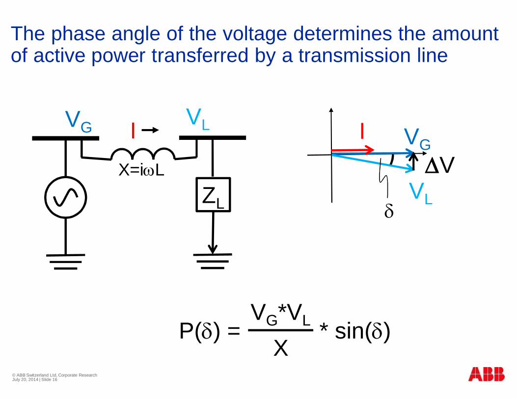
The phase angle of the voltage determines the amountof active power transferred by a transmission line
© ABB Switzerland Ltd, Corporate ResearchJuly 20, 2014 | Slide 16
ZL
VG VLIX=iwL
P(d) = VG*VL * sin(d)VG*VL
X
DVVL
I VG
d
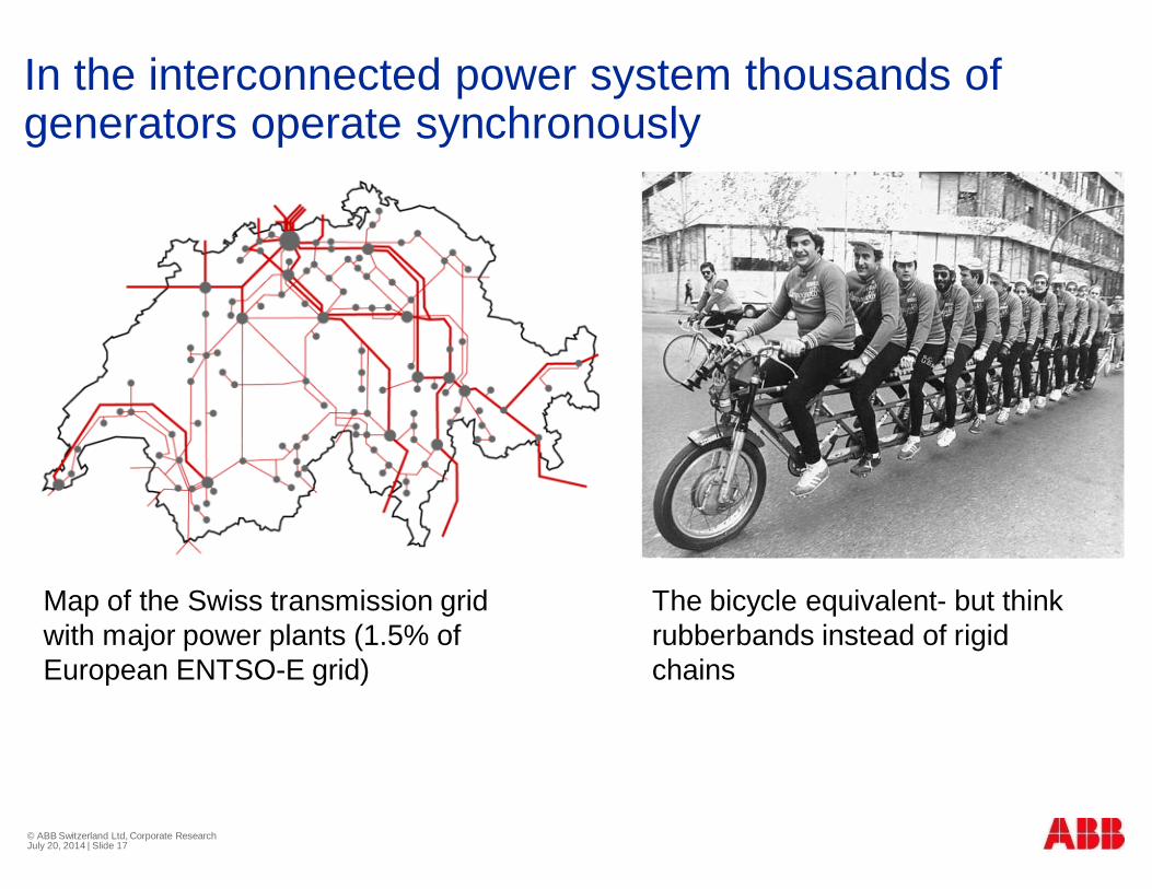
In the interconnected power system thousands ofgenerators operate synchronously
© ABB Switzerland Ltd, Corporate ResearchJuly 20, 2014 | Slide 17
The bicycle equivalent- but thinkrubberbands instead of rigidchains
Map of the Swiss transmission gridwith major power plants (1.5% ofEuropean ENTSO-E grid)

Some power plants contract part of their output forprimary, secondary, tertiary reserve (frequency control)
© ABB Switzerland Ltd, Corporate ResearchJuly 20, 2014 | Slide 18
Pow
er
Timehours
Primary
Secondary
Tertiary
Primary frequency control§ The power plants contracted for primary frequencycontrol act as a proportional controler
§ The power plants contracted for secondaryreserve act as an integral controler
§ If the tertiary reserve is insufficient, the final optionis load sheddingL

Tripping of a nuclear power plant in Hamburg on June28, 2007 measured in Zurich
© ABB Switzerland Ltd, Corporate ResearchJuly 20, 2014 | Slide 19
49.9
49.92
49.94
49.96
49.98
50
50.02
50.04
14.46 Uhr 14.51 Uhr 14.56 Uhr 15.01 Uhr 15.06 Uhr 15.11 Uhr 15.16 Uhr
Freq
uenc
y[H
z]
-1500
-1300
-1100
-900
-700
-500
-300
-100
100
Pow
er[W
]
Frequency [Hz]Power flow [W]
Tolerance band
15:02 KKW Krümmel istaken off the grid.Pnom = 1376MW i.e. almosthalf of the reserve power isneeded
ABB BESS supplies 1ppmof the overall primaryfrequency regulation
3 kW battery supplies 1 ppm

Overhead lines and cables have an impedance, hencethe receiving end voltage depends on the load.
© ABB Switzerland Ltd, Corporate ResearchJuly 20, 2014 | Slide 20
VG
VLI
ZLoad
ZGrid
ZGrid / ZLoad
P / Pmax
I / Ishort
VL / VG
§ In this (unrealistic) example Z(Grid) and Z(Load) are both pure resistancesand the voltage at maximum power transfer is 50% of the sending voltage.

The voltage drop across a transmission line is mainlycaused by the reactive power transferred
© ABB Switzerland Ltd, Corporate ResearchJuly 20, 2014 | Slide 21
ZL
VG VLIX=iwL
Q(DV) = * DV (for d=0)VL
X
DV
VL
I
VG

The maximum real power transfer capability is stronglydependent on the power factor of the load
© ABB Switzerland Ltd, Corporate ResearchJuly 20, 2014 | Slide 22
P / Pmax
VL / VG0.90 lag 0.95 lag 1.0 0.95 lead 0.90 lead
Power factor
Locus of critical points
Source: After Kundur (1994)

The rotor excitation of synchronous generators controlsthe voltage at that grid location
© ABB Switzerland Ltd, Corporate ResearchJuly 20, 2014 | Slide 23
Overexcitation
Underexcitation
Capacitive current
Inductive current
d
d
d
d
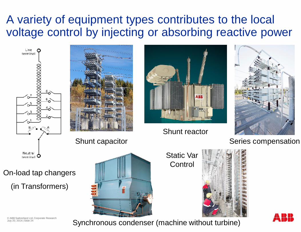
A variety of equipment types contributes to the localvoltage control by injecting or absorbing reactive power
© ABB Switzerland Ltd, Corporate ResearchJuly 20, 2014 | Slide 24
Series compensation
On-load tap changers
(in Transformers)
Shunt reactorShunt capacitor
Synchronous condenser (machine without turbine)
Static VarControl

no load
The elongation due to resistive losses causes a sag ofoverhead lines
clearance
sag§ Resistive losses heats up conductor
§ Heating causes elongation
§ Elongation causes sag
§ Sag reduces clearance
§ Severe overtemperature causesannealing
Minimum
clearance
sag
maximum load

Short lines can be loaded to the thermal limit, longerlines are limited by voltage drop and angle stability
0 80 320 1000Line Length (kms)
Line
Load
abilit
yThermal limit
anglestability limit
UnusedThermal capacity
voltagedrop limit
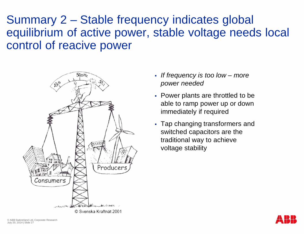
Summary 2 – Stable frequency indicates globalequilibrium of active power, stable voltage needs localcontrol of reacive power
§ If frequency is too low – morepower needed
§ Power plants are throttled to beable to ramp power up or downimmediately if required
§ Tap changing transformers andswitched capacitors are thetraditional way to achievevoltage stability
© ABB Switzerland Ltd, Corporate ResearchJuly 20, 2014 | Slide 27

Renewables Integration
(3)
© ABB Switzerland Ltd, Corporate ResearchJuly 20, 2014 | Slide 28

The power electronic converter lets the solar cell looklike a synchronous generator
§ Power semiconductors switch on/off with high frequency
§ Output is smoothened with low pass filters
§ Power converters can
§ Maximize the output power of the solar cell
§ While generating or consuming reactive power
© ABB Switzerland Ltd, Corporate ResearchJuly 20, 2014 | Slide 29

Integration of power from wind and sun into the powersystem is a challenge, but can be done
§ New location for feeding power into the grid
èGrid upgrades and voltage control withpower electronic converters
§ Larger reserve requirements (prediction error)
è Renewables can also take the role ofreserve (trade-off with energy yield)
§ Wind and sun are contingent, statisticalenergy sourcesà Need to give economicincentive to
§ grid upgrades
§ complementary power plant technologywith fast ramp rate, capacity credits
§ energy storage© ABB Switzerland Ltd, Corporate ResearchJuly 20, 2014 | Slide 30

Summary of this PresentationPhysical Aspects of Power Systems Control
(1) High voltage alternating current for low losses.àWehave to deal with reactive power.
(2) Frequency low.à More active power needed. Voltagedepends on local reactive power balance.
(3) PV and wind power can contribute to voltage control (andfrequency control), but their intermittent statistical natureincreases the frequency reserve requirements. And they arecontingent and statistical by nature.
© ABB Switzerland Ltd, Corporate ResearchJuly 20, 2014 | Slide 31

© ABB Switzerland Ltd, Corporate ResearchJuly 20, 2014 | Slide 32
Photo: Michael Ploss