chutes part 5: rock linings
TRANSCRIPT
© Catchments & Creeks Pty Ltd Version 2 - July 2010 Page 1
Chutes Part 5: Rock linings DRAINAGE CONTROL TECHNIQUE
Low Gradient Velocity Control Short-Term ✔
Steep Gradient ✔ Channel Lining Medium-Long Term ✔
Outlet Control [1] Soil Treatment Permanent [2]
[1] Chutes can act as stable outlet structures for Catch Drains and Flow Diversion Banks.
[2] The design of permanent chutes may require consideration of issues not discussed here.
Symbol
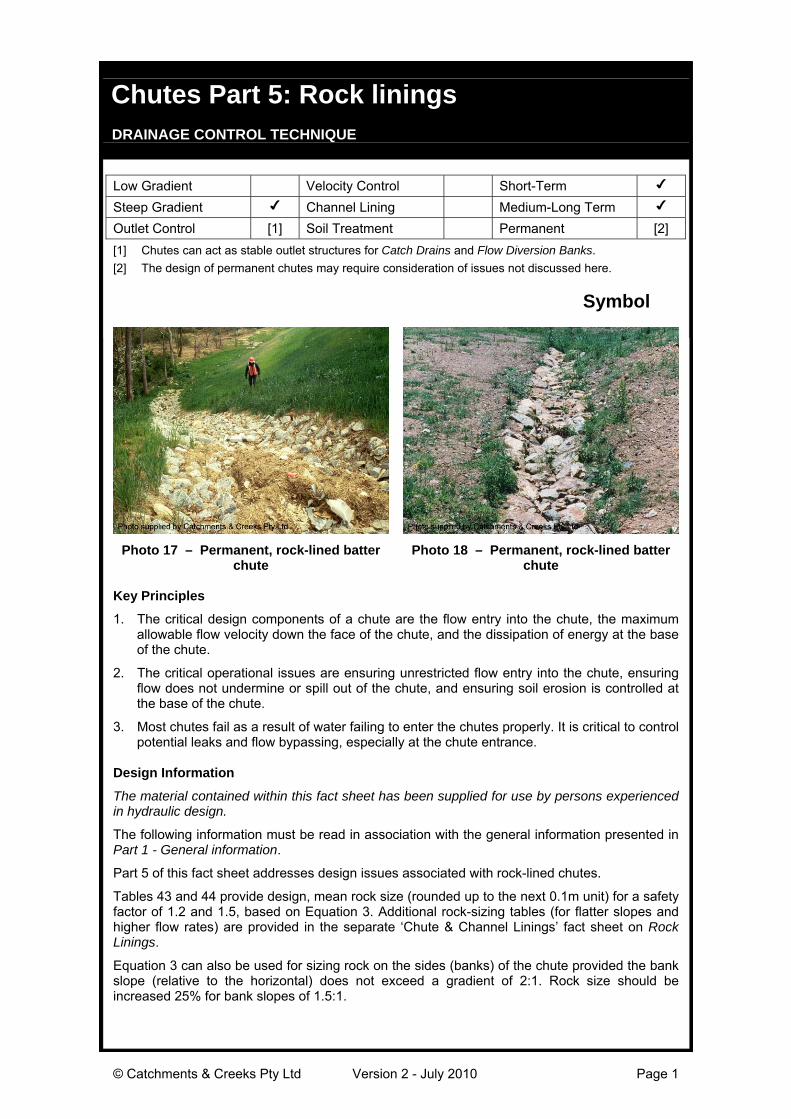
Photo 17 – Permanent, rock-lined batterchute
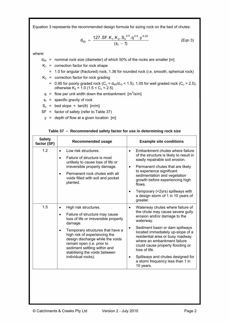
Photo 18 – Permanent, rock-lined batterchute
Key Principles
1. The critical design components of a chute are the flow entry into the chute, the maximumallowable flow velocity down the face of the chute, and the dissipation of energy at the baseof the chute.
2. The critical operational issues are ensuring unrestricted flow entry into the chute, ensuringflow does not undermine or spill out of the chute, and ensuring soil erosion is controlled atthe base of the chute.
3. Most chutes fail as a result of water failing to enter the chutes properly. It is critical to controlpotential leaks and flow bypassing, especially at the chute entrance.
Design Information
The material contained within this fact sheet has been supplied for use by persons experiencedin hydraulic design.
The following information must be read in association with the general information presented inPart 1 - General information.
Part 5 of this fact sheet addresses design issues associated with rock-lined chutes.
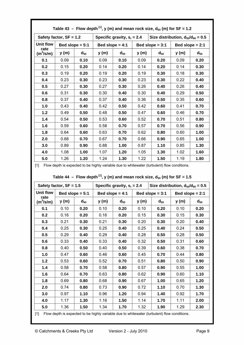
Tables 43 and 44 provide design, mean rock size (rounded up to the next 0.1m unit) for a safetyfactor of 1.2 and 1.5, based on Equation 3. Additional rock-sizing tables (for flatter slopes andhigher flow rates) are provided in the separate ‘Chute & Channel Linings’ fact sheet on RockLinings.
Equation 3 can also be used for sizing rock on the sides (banks) of the chute provided the bankslope (relative to the horizontal) does not exceed a gradient of 2:1. Rock size should beincreased 25% for bank slopes of 1.5:1.
© Catchments & Creeks Pty Ltd Version 2 - July 2010 Page 2
Equation 3 represents the recommended design formula for sizing rock on the bed of chutes.
dSF K K S q y
so
r50
1 20 5 0 5 0 25127
1
. . . . . . .
( )
. . .
(Eqn 3)
where:
d50 = nominal rock size (diameter) of which 50% of the rocks are smaller [m]
K1 = correction factor for rock shape
= 1.0 for angular (fractured) rock, 1.36 for rounded rock (i.e. smooth, spherical rock)
K2 = correction factor for rock grading
= 0.95 for poorly graded rock (Cu = d60/d10 < 1.5), 1.05 for well graded rock (Cu > 2.5),otherwise K2 = 1.0 (1.5 < Cu < 2.5)
q = flow per unit width down the embankment [m3/s/m]
sr = specific gravity of rock
So = bed slope = tan(θ) [m/m]
SF = factor of safety (refer to Table 37)
y = depth of flow at a given location [m]
Table 37 – Recommended safety factor for use in determining rock size
Safetyfactor (SF) Recommended usage Example site conditions
1.2 Low risk structures.
Failure of structure is mostunlikely to cause loss of life orirreversible property damage.
Permanent rock chutes with allvoids filled with soil and pocketplanted.
Embankment chutes where failureof the structure is likely to result ineasily repairable soil erosion.
Permanent chutes that are likelyto experience significantsedimentation and vegetationgrowth before experiencing highflows.
Temporary (<2yrs) spillways witha design storm of 1 in 10 years ofgreater.
1.5 High risk structures.
Failure of structure may causeloss of life or irreversible propertydamage.
Temporary structures that have ahigh risk of experiencing thedesign discharge while the voidsremain open (i.e. prior tosediment settling within andstabilising the voids betweenindividual rocks).
Waterway chutes where failure ofthe chute may cause severe gullyerosion and/or damage to thewaterway.
Sediment basin or dam spillwayslocated immediately up-slope of aresidential area or busy roadwaywhere an embankment failurecould cause property flooding orloss of life.
Spillways and chutes designed fora storm frequency less than 1 in10 years.
© Catchments & Creeks Pty Ltd Version 2 - July 2010 Page 3
Design unit flow rate (q), flow velocity (V), and flow depth (y):
Wherever practical, the unit flow rate ‘q’ (m3/s/m), flow velocity ‘V’ (m/s), and flow depth ‘y’ (m)used to determine rock size should be based on the ‘local’ conditions (e.g. the unit flow rate at agiven location within the chute cross-section, or the depth-average flow velocity at a givenlocation), rather than a value averaged over the full cross-section.
Rock type, size and grading:
The rock should be durable and resistant to weathering, and should be proportioned so thatneither the breadth nor the thickness of a single rock is less than one-third its length. Generally,crushed (angular) rock is more stable than rounded stone.
Typical relative densities of various types of rock are provided in Table 38.
Table 38 – Typical relative density (specific gravity) of rock
Rock type Relative density (sr)
Sandstone 2.1 to 2.4
Granite 2.5 to 3.1, commonly 2.6
Limestone 2.6
Basalt 2.7 to 3.2
The maximum rock size should generally not exceed twice the nominal (d50) rock size.
Table 39 provides a typical rock size distribution for use in preliminary design. Table 39 isprovided for general information only, it does not represent a recommended designspecification.
Table 39 – Typical distribution of rock size [1]
Rock size ratio Assumed distribution value
d100/d50 2.00
d90/d50 1.82
d75/d50 1.50
d65/d50 1.28
d40/d50 0.75
d33/d50 0.60
d10/d50 > 0.50
[1] Wide variations in the rock size distribution can occur unless suitably controlled by the materialcontract specifications.
Thickness of rock protection:
The thickness of the rock protection should be sufficient to allow at least two overlapping layersof the nominal (d50) rock size.
The thickness of rock protection must also be sufficient to accommodate the largest rock size.
In order to allow at least two layers of rock, the minimum thickness of rock protection (T) can beapproximated by the values presented in Table 40.
Table 40 – Minimum thickness (T) of rock lining
Min. Thickness (T) Size distribution (d50/d90) Description
1.4 d50 1.0 Highly uniform rock size
1.6 d50 0.8 Typical upper limit of quarry rock
1.8 d50 0.67 Recommended lower limit of distribution
2.1 d50 0.5 Typical lower limit of quarry rock
© Catchments & Creeks Pty Ltd Version 2 - July 2010 Page 4
Backing material or filter layer:
Non-vegetated armour rock must be placed over a layer of suitably graded filter rock orgeotextile filter cloth (minimum bidim A24 or the equivalent). The geotextile filter cloth must havesufficient strength and must be suitably overlapped to withstand the placement of the rock.
Armour rock that is intended to be vegetated by appropriately filling all voids with soil and pocketplanting, generally will not require an underlying filter layer, unless the long-term viability of thevegetation is questioned due to possible high scour velocities, or limited natural light or rainfallconditions.
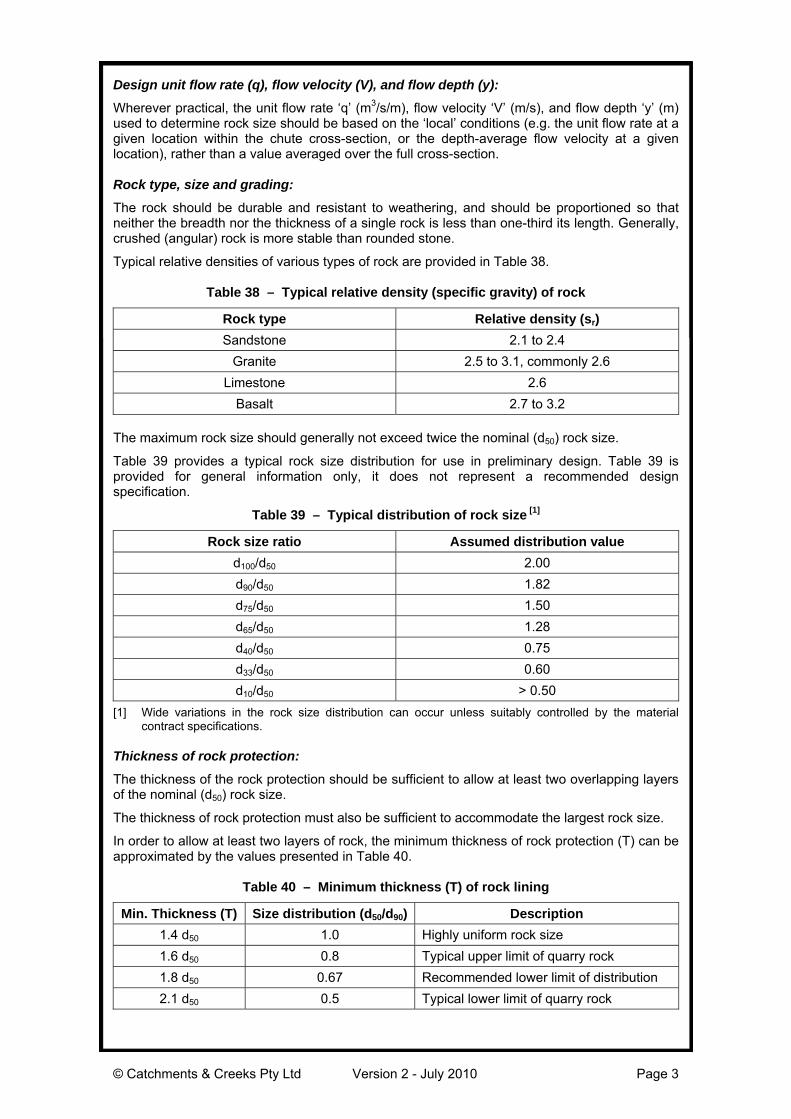
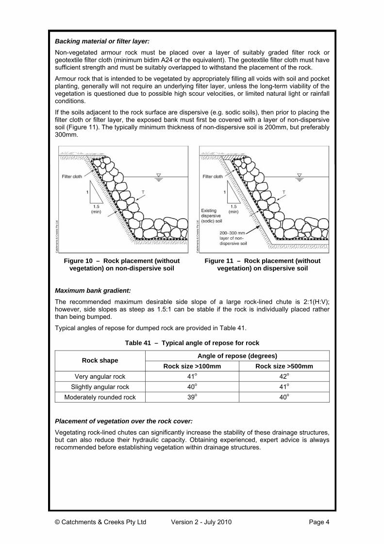
If the soils adjacent to the rock surface are dispersive (e.g. sodic soils), then prior to placing thefilter cloth or filter layer, the exposed bank must first be covered with a layer of non-dispersivesoil (Figure 11). The typically minimum thickness of non-dispersive soil is 200mm, but preferably300mm.
Figure 10 – Rock placement (withoutvegetation) on non-dispersive soil
Figure 11 – Rock placement (withoutvegetation) on dispersive soil
Maximum bank gradient:
The recommended maximum desirable side slope of a large rock-lined chute is 2:1(H:V);however, side slopes as steep as 1.5:1 can be stable if the rock is individually placed ratherthan being bumped.
Typical angles of repose for dumped rock are provided in Table 41.
Table 41 – Typical angle of repose for rock
Angle of repose (degrees)Rock shape
Rock size >100mm Rock size >500mm
Very angular rock 41o 42o
Slightly angular rock 40o 41o
Moderately rounded rock 39o 40o
Placement of vegetation over the rock cover:
Vegetating rock-lined chutes can significantly increase the stability of these drainage structures,but can also reduce their hydraulic capacity. Obtaining experienced, expert advice is alwaysrecommended before establishing vegetation within drainage structures.
© Catchments & Creeks Pty Ltd Version 2 - July 2010 Page 5
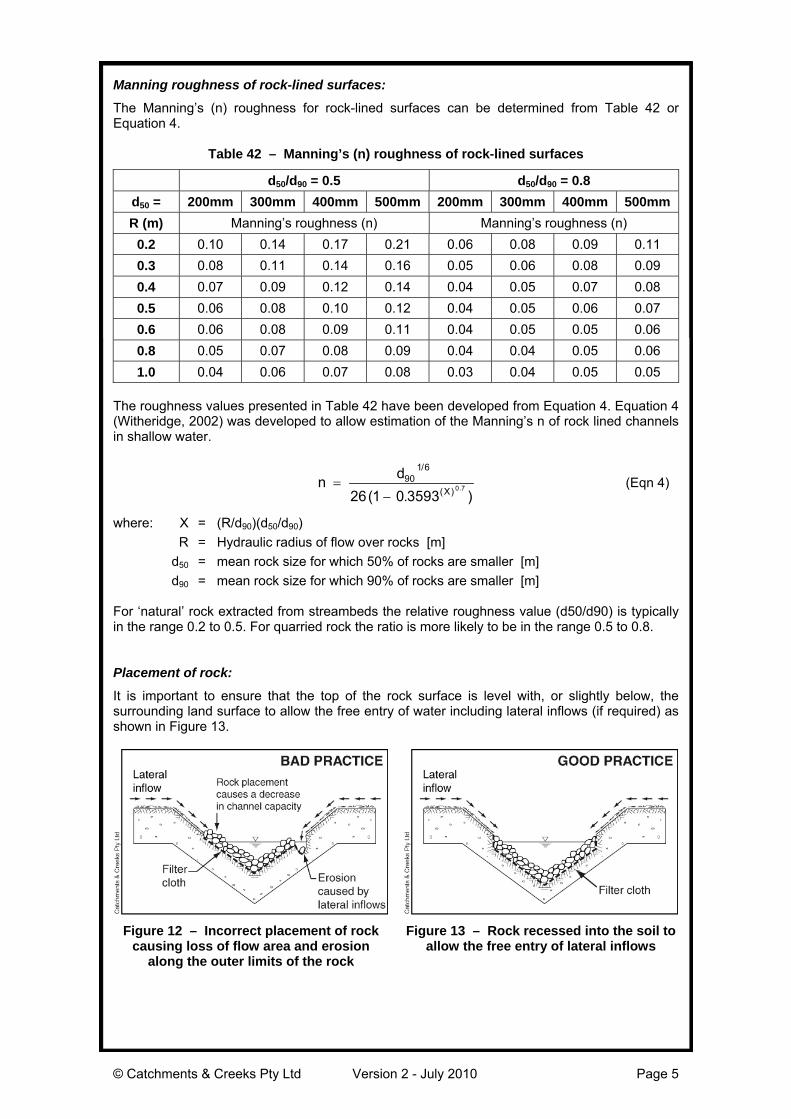
Manning roughness of rock-lined surfaces:
The Manning’s (n) roughness for rock-lined surfaces can be determined from Table 42 orEquation 4.
Table 42 – Manning’s (n) roughness of rock-lined surfaces
d50/d90 = 0.5 d50/d90 = 0.8
d50 = 200mm 300mm 400mm 500mm 200mm 300mm 400mm 500mm
R (m) Manning’s roughness (n) Manning’s roughness (n)
0.2 0.10 0.14 0.17 0.21 0.06 0.08 0.09 0.11
0.3 0.08 0.11 0.14 0.16 0.05 0.06 0.08 0.09
0.4 0.07 0.09 0.12 0.14 0.04 0.05 0.07 0.08
0.5 0.06 0.08 0.10 0.12 0.04 0.05 0.06 0.07
0.6 0.06 0.08 0.09 0.11 0.04 0.05 0.05 0.06
0.8 0.05 0.07 0.08 0.09 0.04 0.04 0.05 0.06
1.0 0.04 0.06 0.07 0.08 0.03 0.04 0.05 0.05
The roughness values presented in Table 42 have been developed from Equation 4. Equation 4(Witheridge, 2002) was developed to allow estimation of the Manning’s n of rock lined channelsin shallow water.
nd
X
90
1 6
26 1 0 35930 7
/
( )( . ). (Eqn 4)
where: X = (R/d90)(d50/d90)
R = Hydraulic radius of flow over rocks [m]
d50 = mean rock size for which 50% of rocks are smaller [m]
d90 = mean rock size for which 90% of rocks are smaller [m]
For ‘natural’ rock extracted from streambeds the relative roughness value (d50/d90) is typicallyin the range 0.2 to 0.5. For quarried rock the ratio is more likely to be in the range 0.5 to 0.8.
Placement of rock:
It is important to ensure that the top of the rock surface is level with, or slightly below, thesurrounding land surface to allow the free entry of water including lateral inflows (if required) asshown in Figure 13.
Figure 12 – Incorrect placement of rockcausing loss of flow area and erosion
along the outer limits of the rock
Figure 13 – Rock recessed into the soil toallow the free entry of lateral inflows
© Catchments & Creeks Pty Ltd Version 2 - July 2010 Page 6
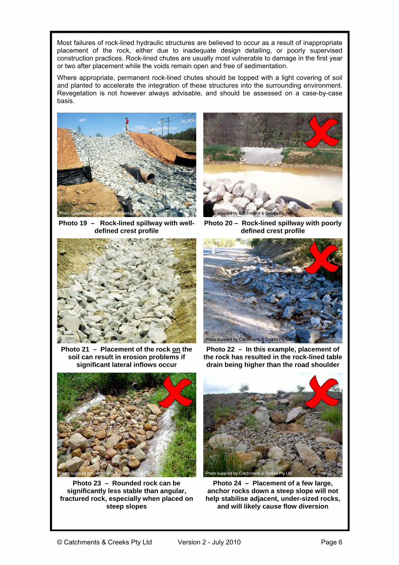
Most failures of rock-lined hydraulic structures are believed to occur as a result of inappropriateplacement of the rock, either due to inadequate design detailing, or poorly supervisedconstruction practices. Rock-lined chutes are usually most vulnerable to damage in the first yearor two after placement while the voids remain open and free of sedimentation.
Where appropriate, permanent rock-lined chutes should be topped with a light covering of soiland planted to accelerate the integration of these structures into the surrounding environment.Revegetation is not however always advisable, and should be assessed on a case-by-casebasis.
Photo 19 – Rock-lined spillway with well-defined crest profile
Photo 20 – Rock-lined spillway with poorlydefined crest profile
Photo 21 – Placement of the rock on thesoil can result in erosion problems if
significant lateral inflows occur
Photo 22 – In this example, placement ofthe rock has resulted in the rock-lined tabledrain being higher than the road shoulder
Photo 23 – Rounded rock can besignificantly less stable than angular,
fractured rock, especially when placed onsteep slopes
Photo 24 – Placement of a few large,anchor rocks down a steep slope will nothelp stabilise adjacent, under-sized rocks,
and will likely cause flow diversion
© Catchments & Creeks Pty Ltd Version 2 - July 2010 Page 7
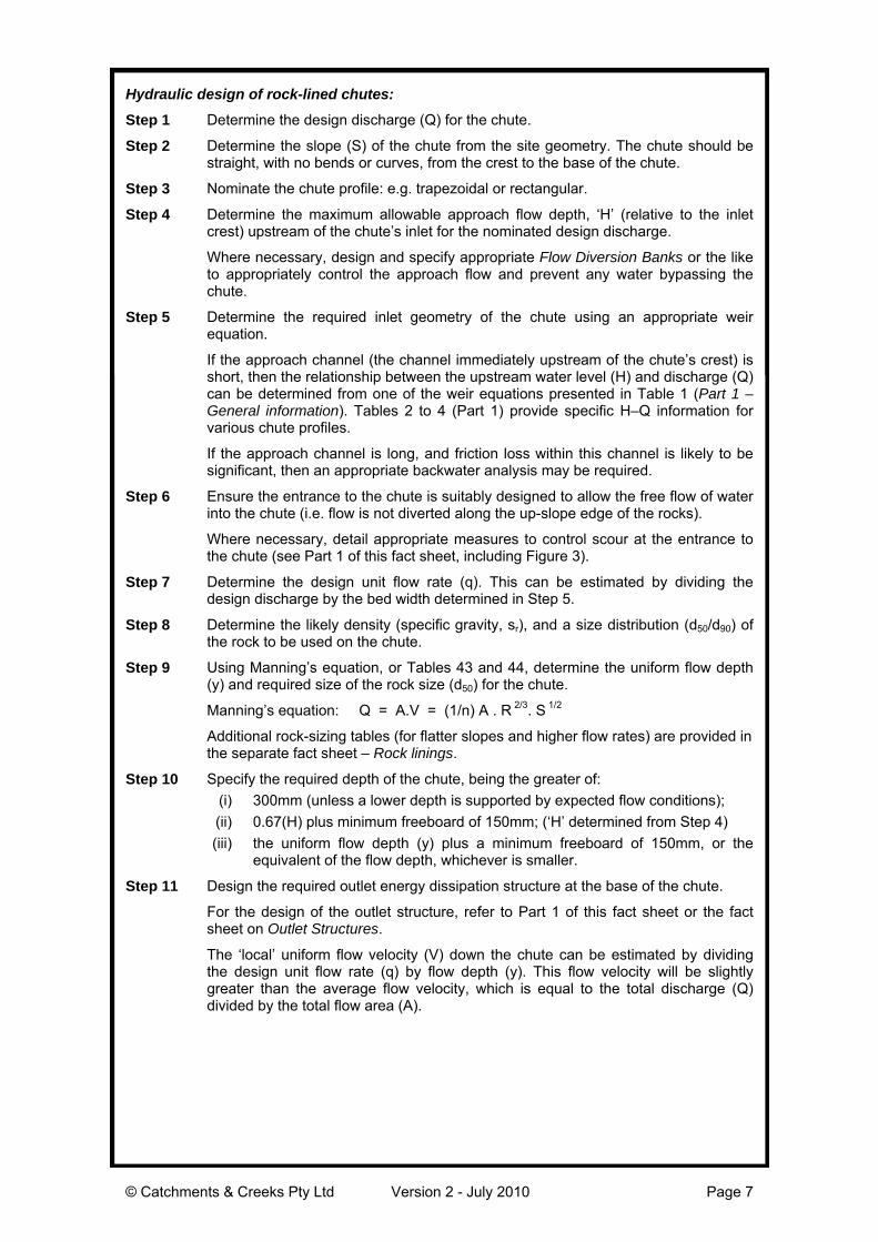
Hydraulic design of rock-lined chutes:
Step 1 Determine the design discharge (Q) for the chute.
Step 2 Determine the slope (S) of the chute from the site geometry. The chute should bestraight, with no bends or curves, from the crest to the base of the chute.
Step 3 Nominate the chute profile: e.g. trapezoidal or rectangular.
Step 4 Determine the maximum allowable approach flow depth, ‘H’ (relative to the inletcrest) upstream of the chute’s inlet for the nominated design discharge.
Where necessary, design and specify appropriate Flow Diversion Banks or the liketo appropriately control the approach flow and prevent any water bypassing thechute.
Step 5 Determine the required inlet geometry of the chute using an appropriate weirequation.
If the approach channel (the channel immediately upstream of the chute’s crest) isshort, then the relationship between the upstream water level (H) and discharge (Q)can be determined from one of the weir equations presented in Table 1 (Part 1 –General information). Tables 2 to 4 (Part 1) provide specific H–Q information forvarious chute profiles.
If the approach channel is long, and friction loss within this channel is likely to besignificant, then an appropriate backwater analysis may be required.
Step 6 Ensure the entrance to the chute is suitably designed to allow the free flow of waterinto the chute (i.e. flow is not diverted along the up-slope edge of the rocks).
Where necessary, detail appropriate measures to control scour at the entrance tothe chute (see Part 1 of this fact sheet, including Figure 3).
Step 7 Determine the design unit flow rate (q). This can be estimated by dividing thedesign discharge by the bed width determined in Step 5.
Step 8 Determine the likely density (specific gravity, sr), and a size distribution (d50/d90) ofthe rock to be used on the chute.
Step 9 Using Manning’s equation, or Tables 43 and 44, determine the uniform flow depth(y) and required size of the rock size (d50) for the chute.
Manning’s equation: Q = A.V = (1/n) A . R 2/3. S 1/2
Additional rock-sizing tables (for flatter slopes and higher flow rates) are provided inthe separate fact sheet – Rock linings.
Step 10 Specify the required depth of the chute, being the greater of:
(i) 300mm (unless a lower depth is supported by expected flow conditions);
(ii) 0.67(H) plus minimum freeboard of 150mm; (‘H’ determined from Step 4)
(iii) the uniform flow depth (y) plus a minimum freeboard of 150mm, or theequivalent of the flow depth, whichever is smaller.
Step 11 Design the required outlet energy dissipation structure at the base of the chute.
For the design of the outlet structure, refer to Part 1 of this fact sheet or the factsheet on Outlet Structures.
The ‘local’ uniform flow velocity (V) down the chute can be estimated by dividingthe design unit flow rate (q) by flow depth (y). This flow velocity will be slightlygreater than the average flow velocity, which is equal to the total discharge (Q)divided by the total flow area (A).
© Catchments & Creeks Pty Ltd Version 2 - July 2010 Page 8
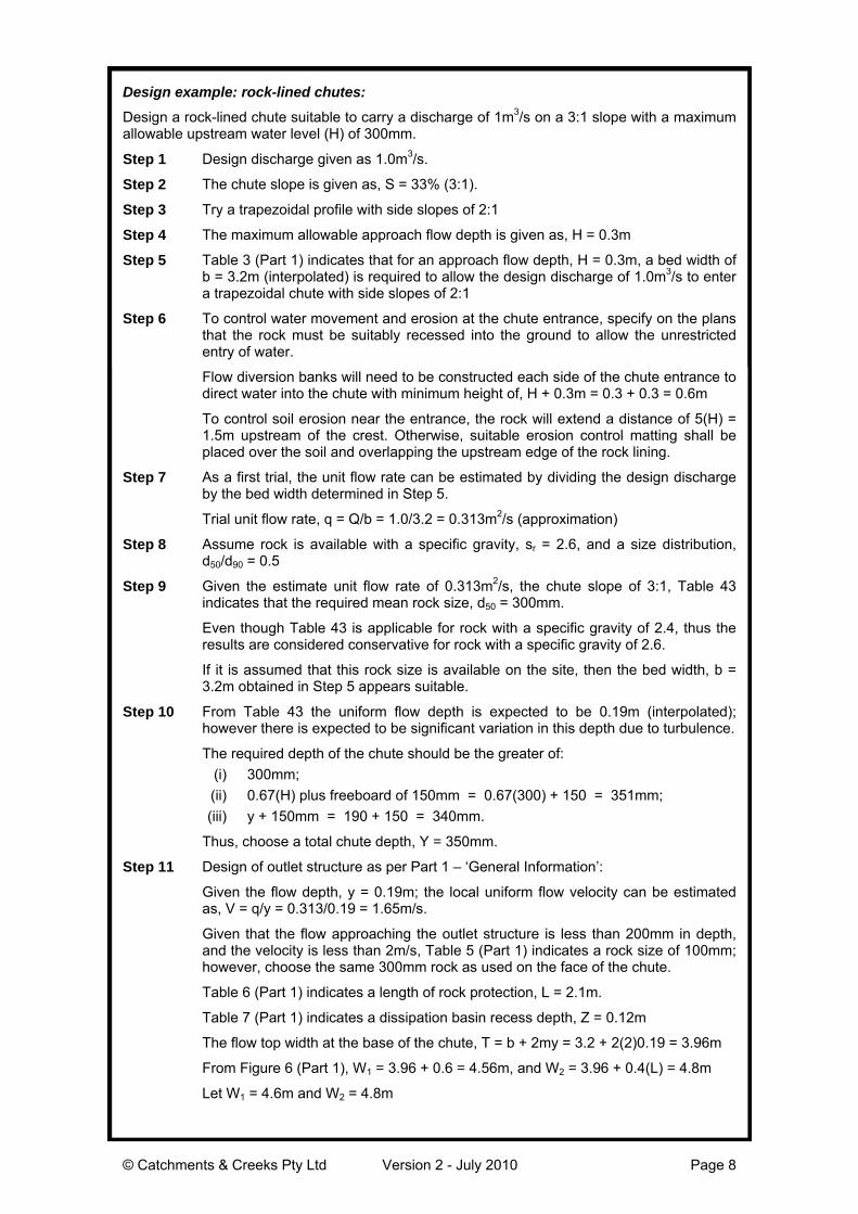
Design example: rock-lined chutes:
Design a rock-lined chute suitable to carry a discharge of 1m3/s on a 3:1 slope with a maximumallowable upstream water level (H) of 300mm.
Step 1 Design discharge given as 1.0m3/s.
Step 2 The chute slope is given as, S = 33% (3:1).
Step 3 Try a trapezoidal profile with side slopes of 2:1
Step 4 The maximum allowable approach flow depth is given as, H = 0.3m
Step 5 Table 3 (Part 1) indicates that for an approach flow depth, H = 0.3m, a bed width ofb = 3.2m (interpolated) is required to allow the design discharge of 1.0m3/s to entera trapezoidal chute with side slopes of 2:1
Step 6 To control water movement and erosion at the chute entrance, specify on the plansthat the rock must be suitably recessed into the ground to allow the unrestrictedentry of water.
Flow diversion banks will need to be constructed each side of the chute entrance todirect water into the chute with minimum height of, H + 0.3m = 0.3 + 0.3 = 0.6m
To control soil erosion near the entrance, the rock will extend a distance of 5(H) =1.5m upstream of the crest. Otherwise, suitable erosion control matting shall beplaced over the soil and overlapping the upstream edge of the rock lining.
Step 7 As a first trial, the unit flow rate can be estimated by dividing the design dischargeby the bed width determined in Step 5.
Trial unit flow rate, q = Q/b = 1.0/3.2 = 0.313m2/s (approximation)
Step 8 Assume rock is available with a specific gravity, sr = 2.6, and a size distribution,d50/d90 = 0.5
Step 9 Given the estimate unit flow rate of 0.313m2/s, the chute slope of 3:1, Table 43indicates that the required mean rock size, d50 = 300mm.
Even though Table 43 is applicable for rock with a specific gravity of 2.4, thus theresults are considered conservative for rock with a specific gravity of 2.6.
If it is assumed that this rock size is available on the site, then the bed width, b =3.2m obtained in Step 5 appears suitable.
Step 10 From Table 43 the uniform flow depth is expected to be 0.19m (interpolated);however there is expected to be significant variation in this depth due to turbulence.
The required depth of the chute should be the greater of:
(i) 300mm;
(ii) 0.67(H) plus freeboard of 150mm = 0.67(300) + 150 = 351mm;
(iii) y + 150mm = 190 + 150 = 340mm.
Thus, choose a total chute depth, Y = 350mm.
Step 11 Design of outlet structure as per Part 1 – ‘General Information’:
Given the flow depth, y = 0.19m; the local uniform flow velocity can be estimatedas, V = q/y = 0.313/0.19 = 1.65m/s.
Given that the flow approaching the outlet structure is less than 200mm in depth,and the velocity is less than 2m/s, Table 5 (Part 1) indicates a rock size of 100mm;however, choose the same 300mm rock as used on the face of the chute.
Table 6 (Part 1) indicates a length of rock protection, L = 2.1m.
Table 7 (Part 1) indicates a dissipation basin recess depth, Z = 0.12m
The flow top width at the base of the chute, T = b + 2my = 3.2 + 2(2)0.19 = 3.96m
From Figure 6 (Part 1), W1 = 3.96 + 0.6 = 4.56m, and W2 = 3.96 + 0.4(L) = 4.8m
Let W1 = 4.6m and W2 = 4.8m
© Catchments & Creeks Pty Ltd Version 2 - July 2010 Page 9
Table 43 – Flow depth [1], y (m) and mean rock size, d50 (m) for SF = 1.2
Safety factor, SF = 1.2 Specific gravity, sr = 2.4 Size distribution, d50/d90 = 0.5
Bed slope = 5:1 Bed slope = 4:1 Bed slope = 3:1 Bed slope = 2:1Unit flowrate
(m3/s/m) y (m) d50 y (m) d50 y (m) d50 y (m) d50
0.1 0.09 0.10 0.09 0.10 0.09 0.20 0.09 0.20
0.2 0.15 0.20 0.14 0.20 0.14 0.20 0.14 0.30
0.3 0.19 0.20 0.19 0.20 0.19 0.30 0.18 0.30
0.4 0.23 0.30 0.23 0.30 0.23 0.30 0.22 0.40
0.5 0.27 0.30 0.27 0.30 0.26 0.40 0.26 0.40
0.6 0.31 0.30 0.30 0.40 0.30 0.40 0.29 0.50
0.8 0.37 0.40 0.37 0.40 0.36 0.50 0.35 0.60
1.0 0.43 0.40 0.42 0.50 0.42 0.60 0.41 0.70
1.2 0.49 0.50 0.48 0.50 0.47 0.60 0.46 0.70
1.4 0.54 0.50 0.53 0.60 0.52 0.70 0.51 0.80
1.6 0.59 0.60 0.58 0.70 0.57 0.70 0.56 0.90
1.8 0.64 0.60 0.63 0.70 0.62 0.80 0.60 1.00
2.0 0.68 0.70 0.67 0.70 0.66 0.90 0.65 1.00
3.0 0.89 0.90 0.88 1.00 0.87 1.10 0.85 1.30
4.0 1.08 1.00 1.07 1.20 1.05 1.30 1.02 1.60
5.0 1.26 1.20 1.24 1.30 1.22 1.50 1.19 1.80
[1] Flow depth is expected to be highly variable due to whitewater (turbulent) flow conditions.
Table 44 – Flow depth [1], y (m) and mean rock size, d50 (m) for SF = 1.5
Safety factor, SF = 1.5 Specific gravity, sr = 2.4 Size distribution, d50/d90 = 0.5
Bed slope = 5:1 Bed slope = 4:1 Bed slope = 3:1 Bed slope = 2:1Unit flowrate
(m3/s/m) y (m) d50 y (m) d50 y (m) d50 y (m) d50
0.1 0.10 0.20 0.10 0.20 0.10 0.20 0.10 0.20
0.2 0.16 0.20 0.16 0.20 0.15 0.30 0.15 0.30
0.3 0.21 0.30 0.21 0.30 0.20 0.30 0.20 0.40
0.4 0.25 0.30 0.25 0.40 0.25 0.40 0.24 0.50
0.5 0.29 0.40 0.29 0.40 0.28 0.50 0.28 0.50
0.6 0.33 0.40 0.33 0.40 0.32 0.50 0.31 0.60
0.8 0.40 0.50 0.40 0.50 0.39 0.60 0.38 0.70
1.0 0.47 0.60 0.46 0.60 0.45 0.70 0.44 0.80
1.2 0.53 0.60 0.52 0.70 0.51 0.80 0.50 0.90
1.4 0.58 0.70 0.58 0.80 0.57 0.90 0.55 1.00
1.6 0.64 0.70 0.63 0.80 0.62 0.90 0.60 1.10
1.8 0.69 0.80 0.68 0.90 0.67 1.00 0.65 1.20
2.0 0.74 0.80 0.73 0.90 0.72 1.10 0.70 1.30
3.0 0.97 1.10 0.96 1.20 0.94 1.40 0.92 1.70
4.0 1.17 1.30 1.16 1.50 1.14 1.70 1.11 2.00
5.0 1.36 1.50 1.34 1.70 1.32 1.90 1.29 2.30
[1] Flow depth is expected to be highly variable due to whitewater (turbulent) flow conditions.

© Catchments & Creeks Pty Ltd Version 2 - July 2010 Page 10
Common Problems
Severe erosion problems if rocks areplaced directly on dispersive soil. To reducethe potential for such problems, dispersivesoils should be covered with a minimum200mm layer of non-dispersive soil beforerock placement.
Failure of rock-lined chutes due to theabsence of a suitable filter cloth oraggregate filter layer beneath the primaryarmour rock layer.
Weed invasion of the rock protection canbecome unsightly. The control of weedgrowth can be an expensive, labourintensive exercise.
Rill erosion can occur along the upper edgeof the rock if they are not properly set intothe soil.
Severe rilling along the sides of the chutecan be caused by splash or lateral inflowsbeing deflected by the edge of the chute.
Erosion at the base of the chute caused byinadequate energy dissipation.
Special Requirements
An underlying geotextile or rock filter layeris generally required unless all voids arefilled with soil and pocket planted (thuspreventing the disturbance and release ofunderlying sediments through these voids).
The upper rock surface should blend withsurrounding land to allow water to freelyenter the channel.
Flow Diversion Banks are often required todirect flows into the chute.
Good subsoil drainage and foundations arerequired to stabilise the chute lining.
Site Inspection
Check flow entry conditions to ensure nobypassing, undermining, sedimentation orerosion.
Check for piping failure, scour holes, orbank failures.
Check for erosion around the outer edgesof the treated area.
Ensure the chute is straight.
Ensure the rock size and shape agrees withapproved plan.
Check the thickness of rock application andthe existence of underlying filter layer.
Check for excessive vegetation growth thatmay restrict the channel capacity.
Ensure the outlet is appropriately stabilised.
Installation (chute formation)
1. Refer to approved plans for locationand construction details. If there arequestions or problems with the locationor method of installation, contact theengineer or responsible on-site officerfor assistance.
2. Ensure all necessary soil testing (e.g.soil pH, nutrient levels) and analysishas been completed, and required soiladjustments performed prior to planting.
3. Clear the location for the chute clearingonly what is needed to provide accessfor personnel and equipment forinstallation.
4. Remove roots, stumps, and otherdebris and dispose of them properly.
5. Construct the subgrade to theelevations shown on the plans. Removeall unsuitable material and replace withstable material to achieve the desiredfoundations.
6. If the chute is temporary, then compactthe subgrade to a firm consistency. Ifthe chute is intended to be permanent,then compact and finish the subgradeas specified within the design plans.
7. Avoid compacting the subgrade to acondition that would prevent the turffrom bonding with the subgrade.
8. Ensure the sides of the chute are nosteeper than a 1.5:1 (H:V) slope.
9. Ensure the completed chute hassufficient deep along its full length.
10. Ensure the chute is straight from itscrest to the toe of the chute.
11. On fill slopes, ensure that the soil isadequately compacted for a width of atleast one metre each side of the chuteto minimise the risk of soil erosion,otherwise protect the soil with suitablescour protection measures such as turfor erosion control mats.
12. Place and secure the turf as directed.
13. Install an appropriate outlet structure(energy dissipater) at the base of thechute (refer to separate specifications).
14. Ensure water leaving the chute and theoutlet structure will flow freely withoutcausing undesirable ponding or scour.
15. Appropriately stabilise all disturbedareas immediately after construction.
© Catchments & Creeks Pty Ltd Version 2 - July 2010 Page 11
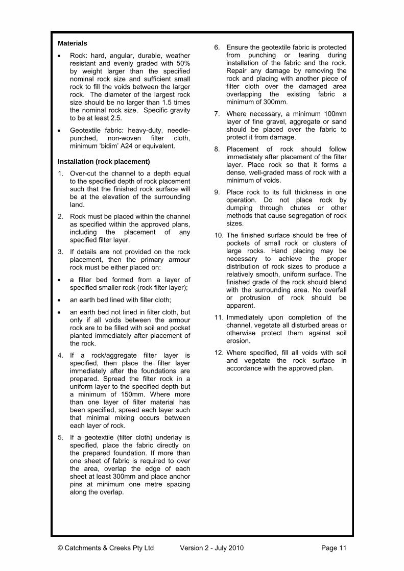
Materials
Rock: hard, angular, durable, weatherresistant and evenly graded with 50%by weight larger than the specifiednominal rock size and sufficient smallrock to fill the voids between the largerrock. The diameter of the largest rocksize should be no larger than 1.5 timesthe nominal rock size. Specific gravityto be at least 2.5.
Geotextile fabric: heavy-duty, needle-punched, non-woven filter cloth,minimum ‘bidim’ A24 or equivalent.
Installation (rock placement)
1. Over-cut the channel to a depth equalto the specified depth of rock placementsuch that the finished rock surface willbe at the elevation of the surroundingland.
2. Rock must be placed within the channelas specified within the approved plans,including the placement of anyspecified filter layer.
3. If details are not provided on the rockplacement, then the primary armourrock must be either placed on:
a filter bed formed from a layer ofspecified smaller rock (rock filter layer);
an earth bed lined with filter cloth;
an earth bed not lined in filter cloth, butonly if all voids between the armourrock are to be filled with soil and pocketplanted immediately after placement ofthe rock.
4. If a rock/aggregate filter layer isspecified, then place the filter layerimmediately after the foundations areprepared. Spread the filter rock in auniform layer to the specified depth buta minimum of 150mm. Where morethan one layer of filter material hasbeen specified, spread each layer suchthat minimal mixing occurs betweeneach layer of rock.
5. If a geotextile (filter cloth) underlay isspecified, place the fabric directly onthe prepared foundation. If more thanone sheet of fabric is required to overthe area, overlap the edge of eachsheet at least 300mm and place anchorpins at minimum one metre spacingalong the overlap.
6. Ensure the geotextile fabric is protectedfrom punching or tearing duringinstallation of the fabric and the rock.Repair any damage by removing therock and placing with another piece offilter cloth over the damaged areaoverlapping the existing fabric aminimum of 300mm.
7. Where necessary, a minimum 100mmlayer of fine gravel, aggregate or sandshould be placed over the fabric toprotect it from damage.
8. Placement of rock should followimmediately after placement of the filterlayer. Place rock so that it forms adense, well-graded mass of rock with aminimum of voids.
9. Place rock to its full thickness in oneoperation. Do not place rock bydumping through chutes or othermethods that cause segregation of rocksizes.
10. The finished surface should be free ofpockets of small rock or clusters oflarge rocks. Hand placing may benecessary to achieve the properdistribution of rock sizes to produce arelatively smooth, uniform surface. Thefinished grade of the rock should blendwith the surrounding area. No overfallor protrusion of rock should beapparent.
11. Immediately upon completion of thechannel, vegetate all disturbed areas orotherwise protect them against soilerosion.
12. Where specified, fill all voids with soiland vegetate the rock surface inaccordance with the approved plan.
© Catchments & Creeks Pty Ltd Version 2 - July 2010 Page 12
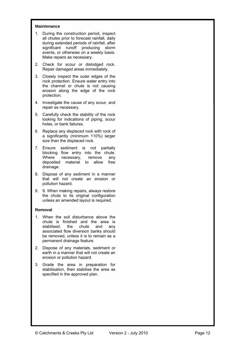
Maintenance
1. During the construction period, inspectall chutes prior to forecast rainfall, dailyduring extended periods of rainfall, aftersignificant runoff producing stormevents, or otherwise on a weekly basis.Make repairs as necessary.
2. Check for scour or dislodged rock.Repair damaged areas immediately.
3. Closely inspect the outer edges of therock protection. Ensure water entry intothe channel or chute is not causingerosion along the edge of the rockprotection.
4. Investigate the cause of any scour, andrepair as necessary.
5. Carefully check the stability of the rocklooking for indications of piping, scourholes, or bank failures.
6. Replace any displaced rock with rock ofa significantly (minimum 110%) largersize than the displaced rock.
7. Ensure sediment is not partiallyblocking flow entry into the chute.Where necessary, remove anydeposited material to allow freedrainage.
8. Dispose of any sediment in a mannerthat will not create an erosion orpollution hazard.
9. 9. When making repairs, always restorethe chute to its original configurationunless an amended layout is required.
Removal
1. When the soil disturbance above thechute is finished and the area isstabilised, the chute and anyassociated flow diversion banks shouldbe removed, unless it is to remain as apermanent drainage feature.
2. Dispose of any materials, sediment orearth in a manner that will not create anerosion or pollution hazard.
3. Grade the area in preparation forstabilisation, then stabilise the area asspecified in the approved plan.