cim for data exchange within a dms for electric...
TRANSCRIPT

www.smartgen.it
CIM for data exchange within a DMS for electric
distribution networks
CIM Users Group Spring 2013 Meeting
Giulia Troglio, Federico Silvestro

Outline
• The SmartGen Project
• Project Architecture
• The adoption of CIM
• Testing Phase
• Conclusion
2

Outline
• The SmartGen Project
• Project Architecture
• The adoption of CIM
• Testing Phase
• Conclusion
3
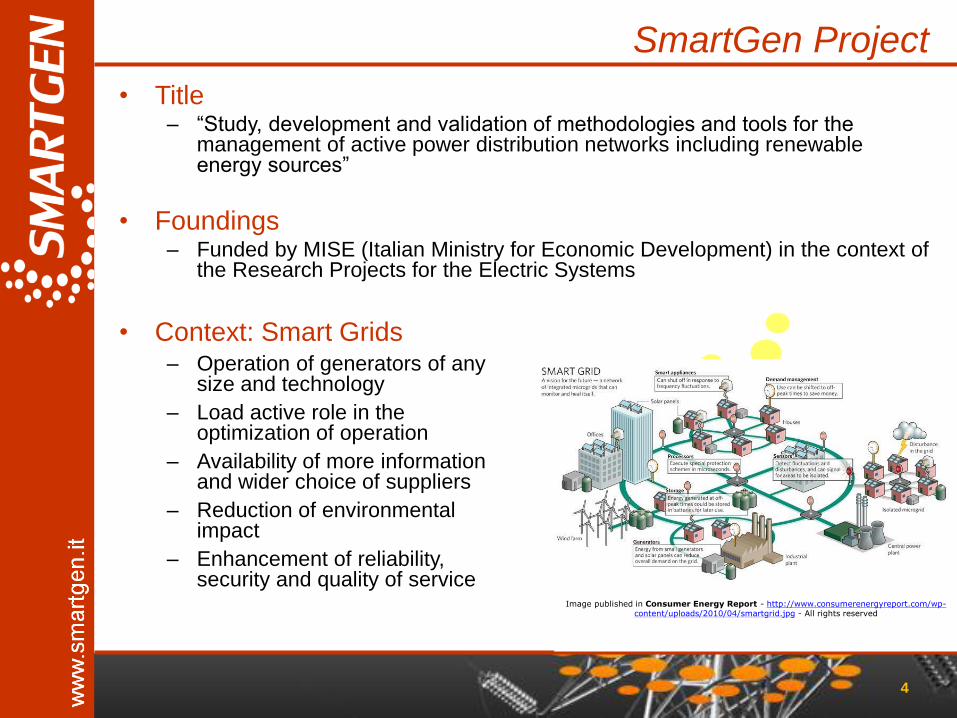
SmartGen Project
• Title – “Study, development and validation of methodologies and tools for the
management of active power distribution networks including renewable energy sources”
• Foundings – Funded by MISE (Italian Ministry for Economic Development) in the context of
the Research Projects for the Electric Systems
4
Image published in Consumer Energy Report - http://www.consumerenergyreport.com/wp-
content/uploads/2010/04/smartgrid.jpg - All rights reserved
• Context: Smart Grids – Operation of generators of any
size and technology
– Load active role in the optimization of operation
– Availability of more information and wider choice of suppliers
– Reduction of environmental impact
– Enhancement of reliability, security and quality of service

Project Consortium
Softeco Sismat S.r.l. Project coordination System integration, automation and communication software, wholesale market management
s.d.i. S.p.A. SCADA & DMS design and implementation, innovative power network management
Enel Engineering and Research System requirements, DMS architecture definition, piloting and demonstration
University of Genova - DINAEL Scientific coordinator DMS architecture, technology survey and enhancement, dissemination
University of Bologna - DIE DMS advanced functionalities and monitoring interfaces
0 24 48 72 96 120 144 1680
0.1
0.2
0.3
0.4
0.5
0.6
0.7
0.8
0.9
1Autumn Load Profiles
Acti
ve P
ow
er (
pu
)
Time (h)
Residential
Agricultural
Industrial
Commercial
Academic research
Industrial infrastructure research
Industrial research
START: January 2011 DURATION: 36 months COSTS > 2.8 M€
Financing = 1.1 M€

SmartGen Project Role
6
1. ENERGY BALANCE Generation / Demand Load curve control
WHOLESALE ELECTRIC MARKET
POWER GRID INFRASTRUCTURE Transmission & distribution network
Microgrid, VPP/VPU
2. GRID SECURITY Network stability Provision continuity / QoS
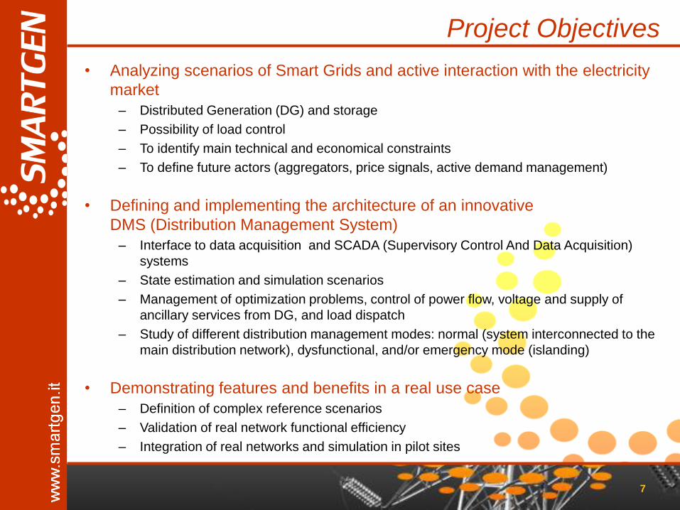
Project Objectives
• Analyzing scenarios of Smart Grids and active interaction with the electricity
market
– Distributed Generation (DG) and storage
– Possibility of load control
– To identify main technical and economical constraints
– To define future actors (aggregators, price signals, active demand management)
• Defining and implementing the architecture of an innovative
DMS (Distribution Management System)
– Interface to data acquisition and SCADA (Supervisory Control And Data Acquisition)
systems
– State estimation and simulation scenarios
– Management of optimization problems, control of power flow, voltage and supply of
ancillary services from DG, and load dispatch
– Study of different distribution management modes: normal (system interconnected to the
main distribution network), dysfunctional, and/or emergency mode (islanding)
• Demonstrating features and benefits in a real use case
– Definition of complex reference scenarios
– Validation of real network functional efficiency
– Integration of real networks and simulation in pilot sites
7

Outline
• The SmartGen Project
• Project Architecture
• The adoption of CIM
• Testing Phase
• Conclusion
8
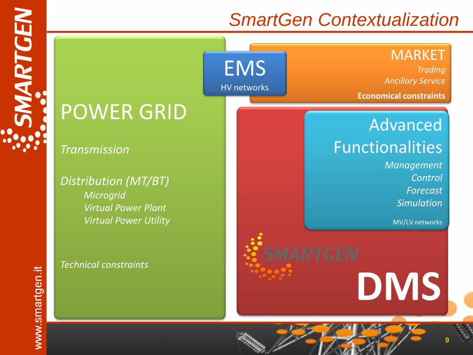
SmartGen Contextualization
9
DMS
POWER GRID Transmission Distribution (MT/BT)
Microgrid Virtual Power Plant Virtual Power Utility
Technical constraints
MARKET Trading
Ancillary Service
Economical constraints
EMS HV networks
Advanced Functionalities
Management Control
Forecast Simulation
MV/LV networks

Architecture - details
10
TECHNICAL CONSTRAINTS (INFRASTRUCTURE)
TECHNICAL CONSTRAINTS (ELECTRICAL NETWORK)
DIS
TRIB
UTI
ON
TR
AN
SMIS
SIO
N
SCA
DA
ECONOMICAL CONSTRAINTS (MARKET)
MV
LV
GENERATION
STORAGE
LOAD
HV/MV
LOCAL CONTROL
GENERATION
STORAGE
LOAD
EMS HV
CO
MM
UN
ICA
TIO
N
SmartGen DMS
ADVANCED FUNCTIONALITIES (ALGORITHMS)
SER
VIC
E B
RO
KER
/ S
CH
EDU
LER
CIM SERVER
OPTIMAL RECONFIGURATION
STATE ESTIMATION
FAULT LOCATION
OPTIMIZATION
SCA
DA
LOAD FORECAST
GENERATION FORECAST
TECHNICAL CONSTRAINTS (SIMULATION)
HISTORIAN DB
CIM DB
REAL TIME DB
CO
MM
UN
ICAT
ION
ACTIVE DEMAND / DSM
OP
C
LOAD/PRODUCTION AGGREGATION
TRADING
ANCILLARY SERVICES
I/O
LOCAL CONTROL
LOCAL CONTROL
LOCAL CONTROL
LOCAL CONTROL
LOCAL CONTROL
MV/LV DECENTRALIZED CONTROL
FAULT LOCATION
DECENTRALIZED CONTROL
FAULT LOCATION

Architecture – control levels
11
TECHNICAL CONSTRAINTS (INFRASTRUCTURE)
TECHNICAL CONSTRAINTS (ELECTRICAL NETWORK)
DIS
TRIB
UTI
ON
TR
AN
SMIS
SIO
N
SCA
DA
ECONOMICAL CONSTRAINTS (MARKET)
MV
LV
GENERATION
STORAGE
LOAD
HV/MV
LOCAL CONTROL
GENERATION
STORAGE
LOAD
EMS HV
CO
MM
UN
ICA
TIO
N
SmartGen DMS
ADVANCED FUNCTIONALITIES (ALGORITHMS)
SER
VIC
E B
RO
KER
/ S
CH
EDU
LER
CIM SERVER
OPTIMAL RECONFIGURATION
STATE ESTIMATION
FAULT LOCATION
OPTIMIZATION
SCA
DA
LOAD FORECAST
GENERATION FORECAST (weather)
TECHNICAL CONSTRAINTS (SIMULATION)
HISTORIAN DB
CIM DB
REAL TIME DB
CO
MM
UN
ICAT
ION
ACTIVE DEMAND / DSM
OP
C
LOAD/PRODUCTION AGGREGATION
TRADING
ANCILLARY SERVICES
I/O
LOCAL CONTROL
LOCAL CONTROL
LOCAL CONTROL
LOCAL CONTROL
LOCAL CONTROL
MV/LV DECENTRALIZED CONTROL
FAULT LOCATION
DECENTRALIZED CONTROL
FAULT LOCATION
2. Decentralized control
3. Local control
1. Central control

DMS Communication
• SmartGen DMS based on – SCADA system, for data acquisition from the field
– CIM Server, as an archive for CIM data
– Advanced DMS component, with smart features
• Communication among DMS components: – Data exchange on a regular basis
• Periodically
• Upon request
– Each system based on its own proprietary format to • Read input data
• Store information
• Write output data
• Need for a universal model for data structure – Data exchange among the DMS components
– Connection to external systems
12
Outline
• The SmartGen Project
• Project Architecture
• The adoption of CIM
• Testing Phase
• Conclusion
13
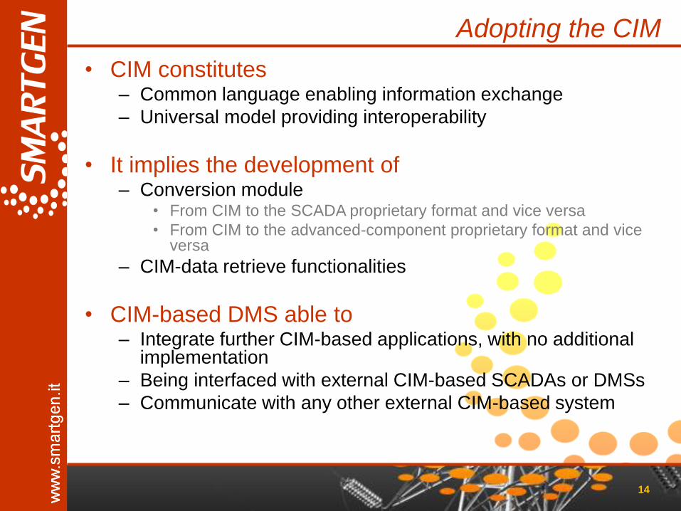
Adopting the CIM
• CIM constitutes – Common language enabling information exchange
– Universal model providing interoperability
• It implies the development of – Conversion module
• From CIM to the SCADA proprietary format and vice versa
• From CIM to the advanced-component proprietary format and vice versa
– CIM-data retrieve functionalities
• CIM-based DMS able to – Integrate further CIM-based applications, with no additional
implementation
– Being interfaced with external CIM-based SCADAs or DMSs
– Communicate with any other external CIM-based system
14

SmartGen CIM Profile
• CIM versions in SmartGen – CIM v14 ENTSO-E 2009 (as exported by DIgSilent)
• SmartGen CIM profile includes: – Elements represented by the SCADA
– Elements of the advanced DMS component
• Standard IEC61970 – Core
– OperationalLimits
– Topology
– Wires
– Generation • Production
– LoadModel
– Meas
– SCADA
– ControlArea
– StateVariables
• Standard IEC 61968 extensions
• Electric Market interface
15
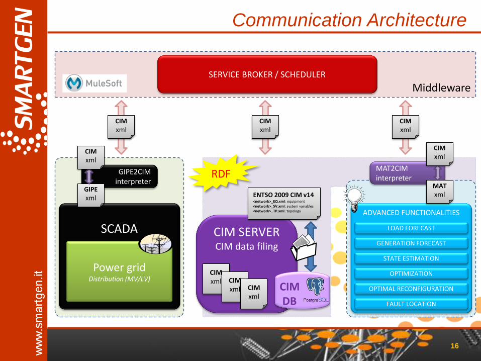
Middleware
Communication Architecture
16
SCADA
Power grid Distribution (MV/LV)
ADVANCED FUNCTIONALITIES
SERVICE BROKER / SCHEDULER
CIM SERVER CIM data filing
CIM xml CIM
xml CIM xml
ENTSO 2009 CIM v14 <network>_EQ.xml: equipment <network>_SV.xml: system variables <network>_TP.xml: topology
CIM DB
RDF GIPE2CIM interpreter
MAT2CIM interpreter
MAT xml
CIM xml
GIPE xml
CIM xml
CIM xml
CIM xml
CIM xml
OPTIMAL RECONFIGURATION
STATE ESTIMATION
FAULT LOCATION
OPTIMIZATION
LOAD FORECAST
GENERATION FORECAST

Output Input
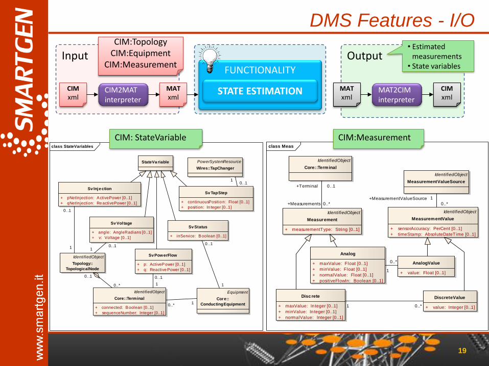
DMS Features - I/O
17
CIM2MAT interpreter
MAT xml
MAT2CIM interpreter
MAT xml
CIM xml
• Estimated measurements
• Set points • Commands
CIM:Topology CIM:Equipment
CIM:Measurement
• Topology • Equipment • Measurements ADVANCED FUNCTIONALITIES
OPTIMAL RECONFIGURATION
STATE ESTIMATION
FAULT LOCATION
OPTIMIZATION
LOAD FORECAST
GENERATION FORECAST
• CIM:Measurement • CIM: StateVariable •…
• Conversion module
– CIM2MAT
• From CIM to the advanced DMS component proprietary format
– MAT2CIM
• From the advanced DMS component proprietary format to CIM
CIM EQ.xml TP.xml MS.xml
Output Input
DMS Features - I/O
18
CIM2MAT interpreter
MAT xml
MAT2CIM interpreter
MAT xml
CIM xml
• Estimated measurements
• Set points • Commands
CIM:Topology CIM:Equipment
CIM:Measurement
• Topology • Equipment • Measurements ADVANCED FUNCTIONALITIES
RECONFIGURATION
STATE ESTIMATION
FAULT LOCATION
OPTIMIZATION
LOAD FORECAST
GENERATION FORECAST
• CIM:Measurement • CIM: StateVariable •…
• Conversion module
– CIM2MAT
• From CIM to the advanced DMS component proprietary format
– MAT2CIM
• From the advanced DMS component proprietary format to CIM
CIM EQ.xml TP.xml MS.xml
Output Input
DMS Features - I/O
19
CIM2MAT interpreter
MAT xml
CIM xml
MAT2CIM interpreter
MAT xml
CIM xml
CIM:Topology CIM:Equipment
CIM:Measurement FUNCTIONALITY
STATE ESTIMATION
class Meas
IdentifiedObject
Measurement
+ measurementType: String [0..1]
IdentifiedObject
Core::Terminal
Analog
+ maxValue: Float [0..1]
+ minValue: Float [0..1]
+ normalValue: Float [0..1]
+ positiveFlowIn: Boolean [0..1]
Disc rete
+ maxValue: In teger [0..1]
+ minValue: In teger [0..1]
+ normalValue: Integer [0..1]
IdentifiedObject
MeasurementValue
+ sensorAccuracy: PerCent [0..1]
+ timeStamp: AbsoluteDateTime [0..1]
AnalogValue
+ value: Float [0..1]
DiscreteValue
+ value: Integer [0..1]
IdentifiedObject
MeasurementValueSource
+MeasurementValueSource 1
0..*
1 0..*
1
0..*
+Measurements 0..*
+Terminal 0. .1
• Estimated measurements
• State variables
CIM:Measurement class StateVariables
StateVa riable
Sv Inje ction
+ pNetInjection: ActivePower [0..1]
+ qNetInjection: Re activePower [0..1]
Sv Vol tage
+ angle: AngleRadians [0..1]
+ v: Voltage [0..1]
Sv Status
+ inService: Boolean [0..1]
Sv PowerFlow
+ p: ActivePower [0..1]
+ q: Reactive Power [0..1]
Sv TapStep
+ continuousPositio n: Float [0..1]
+ position: In teger [0..1]
IdentifiedObject
Core::Terminal
+ connected: Boolean [0..1]
+ sequenceNumber: Integer [0..1]
IdentifiedObject
Topology::
TopologicalNode
Equipment
Core::
ConductingEquipment
PowerSystemResource
Wires::TapChanger
0..*1
0..*
0. .1
0. .11
0. .1
1
0. .1
1
0. .11
0. .1
1
CIM: StateVariable

Output Input
DMS Features - I/O
20
CIM2MAT interpreter
MAT xml
CIM xml
MAT2CIM interpreter
MAT xml
CIM xml
CIM:Topology CIM:Equipment
CIM:Measurement FUNCTIONALITY
OPTIMIZATION
• Generation set points • Generation profiles
class Control
Disc rete Command
ValueAliasSet ValueToAlias
SetPointAnalog
ControlType
Control
Core::Unit
Measurement
0. .1 0. .1
0..*0. .10. .1
0..*
1
1. .*
0. .1
0. .1
10..*
1
0..*
0..*
1
• CIM: SetPoint class SetPoints
IdentifiedObject
Core::Terminal
Wires::TapChanger
ConductingEquipment
Wires::RegulatingCondEq
SeasonDayTypeSchedule
Wires::RegulationSchedule
IdentifiedObject
Meas::Control
Wires::SynchronousMachine
Wires::RegulatingControl
+ discrete: Bo olean [0..1]
+ mode: RegulatingCon trolModeKind [0..1]
+ targetRange: Float [0..1]
+ targetValue: Float [0..1]
IdentifiedObject
Core::PowerSystemResource
«enumeration»
Wires::
RegulatingControlModeKind
«enum»
voltage
activePower
reactivePower
currentFlow
fixed
admit tance
timeScheduled
temperature
powerFactor
Wires::
VoltageControlZone
0. .1
0..*0. .1
0..*
0..*1
0. .1
1. .* 0..*
0. .1
0..*
0. .1
• CIM:RegulationSchedule

Output Input
DMS Features - I/O
21
CIM2MAT interpreter
MAT xml
CIM xml
MAT2CIM interpreter
MAT xml
CIM xml
CIM:Topology CIM:Equipment
CIM:Measurement FUNCTIONALITY
(RE-)CONFIGURATION
Commands Open/close
class Control
Disc rete Command
ValueAliasSet ValueToAlias
SetPointAnalog
ControlType
Control
Core::Unit
Measurement
0. .1 0. .1
0..*0. .10. .1
0..*
1
1. .*
0. .1
0. .1
10..*
1
0..*
0..*
1
class StateVariables
StateVa riable
Sv Inje ction
+ pNetInjection: ActivePower [0..1]
+ qNetInjection: Re activePower [0..1]
Sv Vol tage
+ angle: AngleRadians [0..1]
+ v: Voltage [0..1]
Sv Status
+ inService: Boolean [0..1]
Sv PowerFlow
+ p: ActivePower [0..1]
+ q: Reactive Power [0..1]
Sv TapStep
+ continuousPositio n: Float [0..1]
+ position: In teger [0..1]
IdentifiedObject
Core::Terminal
+ connected: Boolean [0..1]
+ sequenceNumber: Integer [0..1]
IdentifiedObject
Topology::
TopologicalNode
Equipment
Core::
ConductingEquipment
PowerSystemResource
Wires::TapChanger
0..*1
0..*
0. .1
0. .11
0. .1
1
0. .1
1
0. .11
0. .1
1
CIM: StateVariable CIM: Measurement • CIM: Command

Outline
• The SmartGen Project
• Project Architecture
• The adoption of CIM
• Testing Phase
• Conclusion
22
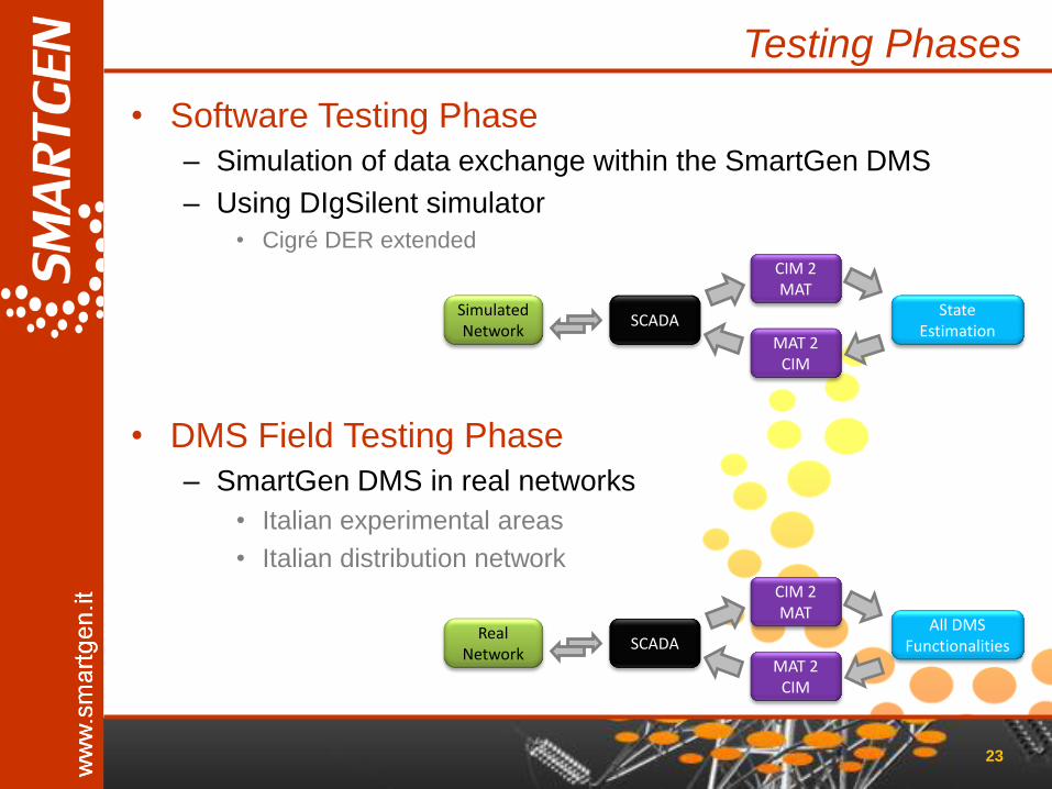
Testing Phases
• Software Testing Phase
– Simulation of data exchange within the SmartGen DMS
– Using DIgSilent simulator
• Cigré DER extended
• DMS Field Testing Phase
– SmartGen DMS in real networks
• Italian experimental areas
• Italian distribution network
23
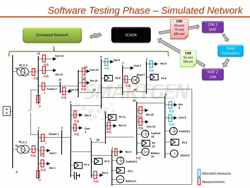
SCADA Simulated Network
State Estimation
CIM 2 MAT
MAT 2 CIM
SCADA Real
Network
All DMS Functionalities
CIM 2 MAT
MAT 2 CIM
HV
0
12
1
TR_0_1
TR_0_2
13
14
2
3
4
5
11
S3
10
9
8
7
S2
6
S1
Feeder 1
Feeder 2
P,Q
V
I
Com 12
Res 12
Com 13
Com 14
Res 14
Res 8
P,Q Com 7
Res 6
Com 1
Res 1
V
I
P,Q
Res 3
P,Q
Com 3
Res 4
Res 11
H2 O
2 + -
Res 5
H2 O
2
+ -
P,Q Res 10
P,Q Com 10
H2 O
2
Res 9
Com 9
CH
P
Allocated measures
Measurements
PV 3 PV 4
PV 5
PV 9 PV 10
PV 6 PV 8
P,Q
P,Q
P,Q
P,Q
P,Q
P,Q P,Q
P,Q
P,Q
P,Q
P,Q
P,Q
P,Q
Diesel 9
FuelCell 9 FuelCell 10
FuelCell 5
Battery 5
Battery 10
P,Q
PV 11
Wind 7
Software Testing Phase – Simulated Network
SCADA Simulated Network
State Estimation
CIM 2 MAT
MAT 2 CIM
P,Q
CIM EQ.xml TP.xml MS.xml
CIM SV.xml MS.xm

Field Testing Phase – Real Networks
• The ensemble of pilot sites was chosen in order to test (in simulated and/or in field) all the SmartGen functions:
– State estimation
– Load/generation forecast
– Optimization of the working point
– Optimal (re-)configuration
– Fault location
• Three sites are identified sites because: – They allow to apply and test a comprehensive combination of the DMS functions
– They already have a good degree of instrumentation
– More activities aimed at the installation of additional instrumentation will be possible
25
Experimental Area ENEL I&R (Livorno)
Distribution netwotk AMAIE SpA (Sanremo)
Microgrid University of Genova
(Genoa)

LOAD
STORAGE
GENERATION
1 - Experimental Area in Livorno - ENEL
26
• Area owned by ENEL INGEGNERIA e RICERCA
• Internal network MV and LV:
– Common services and utilities(300kW)
– Pilot plants for combustion testing (1900kW):
– Experimental plants with distributed generation (1200 kW)
– Experimental storage systems (100 kW)
• Possibility of field tests with no impact on the distributor
• Functionalities that can be demonstrated
– State estimation
– Optimization
– Islanding

2 - Sanremo distribution network - AMAIE
• The portion of the electricity distribution network managed by AMAIE SpA covers
about half of Sanremo’s municipal area and includes both urban and rural areas
• The network is composed of
– A primary substation (HV/MV 132/15 kV)
• double bar structure equipped with 2 transformers of 40 MVA.
– 10 MV feeders, typically managed in a radial structure, departing from the substation
– 115 km of MV lines, both cables and overhead lines. MV network managed in
compensated neutral
– ~ 200 secondary substations (MV/LV 15/0,4 kV), among public and private ones
• Of which about 10% remotely controlled
– ~30.000 users (27.000 for domestic use, 15 for industrial use, 3.000 other)
– ~50 PV plants
• 1 x 470 kW in MV
• 10 x (10-100kW) in LV
• Domestic < 6 kW
27
• Functionalities that can be demonstrated
– Open/close control function
– Fault location
– State estimation

3 - VPP - University of Genoa
28
• Microgrid at a MV/LV substation
– Photovoltaic plant (20 kWp) • Monocrystalline module with 180 Wp.
• Expected production per year: 24,4 MWh
– Storage (10kW/12kWh) • Lithium battery technology
• Controllable loads
– System monitoring and real-time control
• Possibility of field tests with no impact on the distributor
• Functionalities that can be demonstrated
– State estimation
– Optimization
– Islanding
PV Battery
Aux
Substation
Micro SCADA Substation

Outline
• The SmartGen Project
• Project Architecture
• The adoption of CIM
• Testing Phase
• Conclusion
29
Conclusion
• Project advances – Providing enabling technologies for active distribution network management
• Distributed generation / Load control
– Design and development of an advanced DMS, also open to future scenarios of the electricity market
• Network control / energy balance
– The Consortium includes the entire supply chain and integrates the necessary research skills
• Distributors / Universities / Product and service companies
• The adoption of CIM – Provides the SmartGen DMS with interoperability
– Allows the integration of CIM-based applications, with no additional implementation
– Enables to interface the SmartGen DMS with external CIM-based systems, without restricted access
• SmartGen contributes to – Diffusion of CIM as a commonly recognized standard for electrical data
representation
– Extension of CIM for the application to distribution network
30
Dr. Giulia Troglio Softeco Sismat S.r.l. [email protected]
www.smartgen.it
Dr. Federico Silvestro Università di Genova [email protected]
CIM for data exchange within a DMS
for electric distribution networks

HV
0
12
1
TR_0_1
TR_0_2
13
14
2
3
4
5
11
S3
10
9
8
7
S2
6
S1
Feeder 1
Feeder 2
P,Q
V
I
Com 12
Res 12
Com 13
Com 14
Res 14
Res 8
P,Q Com 7
Res 6
Com 1
Res 1
V
I
P,Q
Res 3
P,Q
Com 3
Res 4
Res 11
H2
O2
+ -
Res 5
H2
O2
+ -
P,Q Res 10
P,Q Com 10
H2
O2
Res 9
Com 9
CH
P
Allocated measures
Measurements
PV 3
PV 4
PV 5
PV 9 PV 10
PV 6 PV 8
P,Q
P,Q
P,Q
P,Q
P,Q
P,Q
P,Q
P,Q
P,Q
P,Q
P,Q
P,Q
P,Q
Diesel 9
FuelCell 9 FuelCell 10
FuelCell 5
Battery 5
Battery 10
P,Q
PV 11
Wind 7
Simulated Test Network