circuits lab report exp1
DESCRIPTION
Circuits Lab Report Exp1TRANSCRIPT

Mapua Institute of TechnologyMuralla St., Intramuros, Manila
Department of EE-ECE-CpE
Experiment 1
Familiarization with Electrical Measuring Instruments
EE101L/A8
GROUP # 4
Leader: Ganatuin, John Mitchell
Carino, Karl Mikhail
Cruz, Ignacio
Del Rosario, Adrian
Manuel, Michael Paul
Senires Jr, Gilbert
Date of Performance:
1/14/12
Date of Submission:
1/21/12
Engr. MercadoInstructor

Objectives1. We need to determine the different characteristics and the
proper connection of common electrical measuring devices.2. For us to learn how to read measurements of basic
electrical measuring devices and to measure/compute for values of a resistor using the color coding.
3. And for us to familiarize ourselves to the basic devices like basic circuit training kit, know the proper connections of the trainer kit devices. And also know how to use the V.O.M.
HypothesisExperiment 1, we’re about to familiarize ourselves with the devices and know how to read the measurements using the different measuring devices in the laboratory. Given a set of resistors we got the values of each resistor by using the V.O.M., then also use the volt meter for the voltage, voltage, ammeter for the current flowing and then compute for the power by using the formula P=IV. The last part is to use tina pro to simulate and let us learn the fastest way to know the voltage and current by the use of computer.
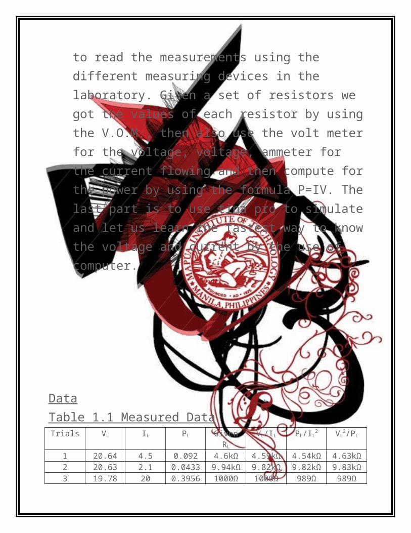
DataTable 1.1 Measured Data
Trials VL IL PL GivenRL
VL/IL PL/IL2 VL
2/PL
1 20.64 4.5 0.092 4.6kΩ 4.59kΩ 4.54kΩ 4.63kΩ2 20.63 2.1 0.0433 9.94kΩ 9.82kΩ 9.82kΩ 9.83kΩ3 19.78 20 0.3956 1000Ω 1000Ω 989Ω 989Ω4 20.07 20 0.4014 1000Ω 1000Ω 1kΩ 1kΩ5 20.65 9 0.1859 2177Ω 2.29kΩ 2.30kΩ 2.29kΩ6 20.66 1 0.0207 21.84kΩ 20.66kΩ 20.7kΩ 20.62kΩ7 20.65 2 0.0413 9.97kΩ 10.33kΩ 10.33kΩ 10.33kΩ8 20.66 0.42 0.0087 46.6kΩ 49.19kΩ 49.32kΩ 49.06kΩ9 20.64 2.1 0.0433 9.97kΩ 9.83kΩ 9.82kΩ 9.84kΩ10 20.64 0.4 0.0083 46.9kΩ 51.6kΩ 51.88kΩ 51.33kΩ
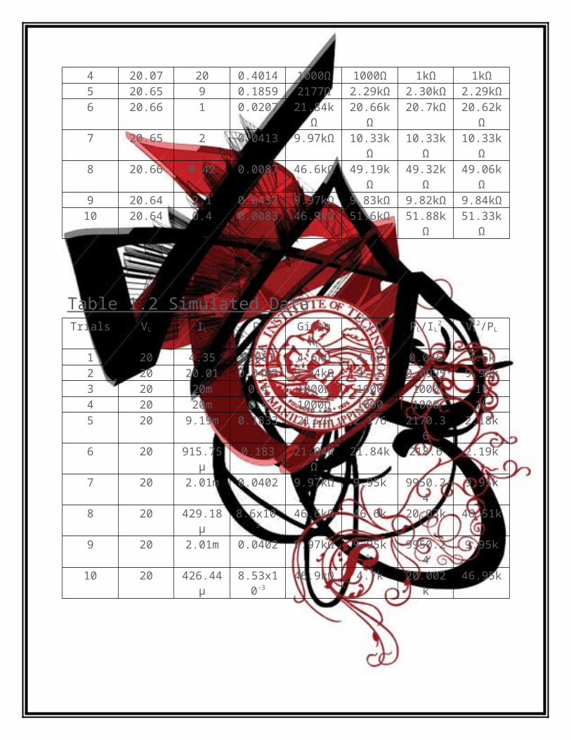
Table 1.2 Simulated DataTrials VL IL PL Given
RL
VL/IL PL/IL2 VL
2/PL
1 20 4.35 0.087 4.6kΩ 4.60 0.046 4.6k2 20 20.01 0.0402 9.94kΩ 9.52 0.0995 9.95k3 20 20m 0.4 1000Ω 1000 1000 1k4 20 20m 0.4 1000Ω 1000 1000 1k5 20 9.19m 0.1833 2177Ω 2.176 2170.36 2.18k6 20 915.75µ 0.183 21.84kΩ 21.84k 218.6 2.19k7 20 2.01m 0.0402 9.97kΩ 9.95k 9950.24 9.95k8 20 429.18µ 8.6x10⁻³ 46.6kΩ 46.6k 20.03k 46.51k9 20 2.01m 0.0402 9.97kΩ 9.95k 9950.24 9.95k10 20 426.44µ 8.53x10⁻³ 46.9kΩ 4.7k 20.002k 46.95k
AnalysisIn Experiment 1, we are focused and familiarized the different measuring instruments regarding electricity and electrical circuits. It was the first time for the group to conduct such experiment. It was the time for them to recognize and familiarize themselves with the different instruments around.
The experiment was divided into two major parts. The first part was again subdivided into three parts wherein the different characteristics of an analog ammeter and an analog voltmeter were to be determined. The other part of the experiment focuses on the usage of a basic circuit trainer kit that will enhance the students with their knowledge about simple circuits and the quantity measurements used in it.
The first part of the experiment is concerned with the determination and observation of the different characteristics of an analog ammeter. The first thing that the group did was to measure the input resistance of the analog meter using the electrical Volt-Ohm Meter or VOM for short. After setting the range and the settings, the group was able to measure 4.4 Ω resistances across the ammeter. We can say that the ammeter really possess and should always possess a very small value of resistance. After then, the group was able to compute for the Voltage Vm that will cause full deflection. The value of the voltage is 4.4 V. We used 1A as our current because according to our instructor, we will use the maximum Ampere that the ammeter can measure as our IT. It is evident that the device only requires enough or a very low amount of voltage in order for a value to be generated and be read by the user. Nevertheless, if anything in the above statement is violated, it might produce or make the ammeter burn that is why it should never be connected in parallel with a load for it will have the same voltage with the other element. Hence, companies only produce ammeters with enough voltage and current in order for it to be used properly.
In the second part of the experiment, the group is to determine the different characteristics of an analog voltmeter. This was done by measuring the input resistance of an analog voltmeter across the input terminals and also through using a Volt-Ohm Meter. The group was able to measure 20.04KΩ which is a correct value because the resistance of voltmeters are precisely and really made large. With the given resistance, the group also computed for the current in the voltmeter. After computing, the group was able to found out that the Current is 500µA. Again we used 10V as our VT, because according to our instructor we will use the maximum value that we can get to our voltmeter as our VT. The Voltmeter Sensitivity was also computed through the reciprocal of the current and the value is 2004 which made us really assured that our voltmeter is accurate. The group found out the sensitivity show how efficient and how effective the voltmeter. As the voltmeter sensitivity increases, the better and the more effective the voltmeter that is used.

In the last part of the experiment, the group was tasked to assemble and measure the corresponding value of the current and voltage in the circuit. The group started choosing different resistors with equivalent values. The group used multiple resistors that are supplied and each has constant resistance. Although the individual resistances of the resistors are already indicated by the respective color codes, the group still measured the resistance through the VOM. We then found out that the reading in the VOM is somehow deviated by the amount of tolerance each resistor possesses. After measuring, the group found out that the only varying factor is current which depends on voltage and resistance of the circuit. It was stated that we use a constant value of 20V but since it was hard for us to gather data, we opted to use resistors that has a large value for us to use 20V. Because low resistance resistor will obviously be destructed by the high voltage, the resulting currents after each trial vary.
Then the group was also tasked to compute for the power dissipated during its flow in each resistor. This is then done by simple having the product of the voltage (VL) to the current (IL) indicated in the ammeter. The group used manual computations for the computation part because we’re not very good at using Microsoft Excel. The last three tables were used to determine the resistance of the resistors obtained from the values in the ammeter, the voltmeter and the Power. Through manipulating the formula, different formulas were derived which are:
(1)V L
I L, (2)
PL
I L2 , and (3)
V L2
PL
. It was observe that there is a difference between the original and
computed resistance yet only small differences was observed. Through using a Computer Software which is Tina Pro, we simulated the values and we gathered the data which produces almost the same values we gathered in the first table. The result of the software showed and verified that we have done the experiment correctly and we were able to gather the corresponding values in the correct manner.

ConclusionThrough the experiment, the we were able to determine the characteristics and the proper way of connecting common electrical measuring devices such as ammeter, and Volt-Ohm meter. We were also able to learn how to read measurements of these basic electrical measuring devices. Lastly, we were able to be acquainted with the basic circuit training kit and learn how it is properly handled.
In the Experiment, we were able to gather new information with regarding Basic Electrical Circuits. We learned that in order to have a useful ammeter, an additional resistance called shunt resistor must be placed parallel to it. The group also found out that a voltmeter measures the voltage drop and is in parallel with the circuit while an ammeter measures the current and is in series with the circuit.
The group were also able to distinguish some of the major characteristics of an analog ammeter, a voltmeter, and a digital VOM. The internal resistance of an analog ammeter is really made small so that when it is connected in series with a circuit, it will not absorb most of the voltage across the circuit so as not affecting the flow of current throughout the circuit. Same goes for an analog voltmeter, wherein its internal resistance is intentionally made very large to minimize the amount of current being drawn from the circuit; and since its purpose is to measure voltage across a load, it has to be in parallel with that element so that they will share the same amount of voltage. In order to extend the range of the voltmeter can measure, series multiplier resistors are placed inside it and it is connected in series with the basic meter. This will help and increase the total resistance of the voltmeter whenever there is an excessive flow of current through it.
We were also able to know one important practice in the laboratory and it is to be able to carry out the correct way of connecting the terminals of different elements in a circuit. The ammeter has several terminals depending on the range of current to be measured. We learned that we must start with the highest range of the current in order for it not to break.
The group concludes that in a given linear circuit containing a resistor, the amount of current being drawn by the resistor is inversely proportional to the total resistance of the resistor when the voltage source is held constant. We have seen and obeyed Ohm’s law through increasing the resistance of the resistor and so the current in it flow in a decreasing aspect. We also conclude that familiarization with the different electrical measuring instruments is a very essential thing for us engineering students in order for us to understand fully the other experiments that we will perform and conduct.

Questions and Answers1. Describe the type of meter movement used in the analog meters.
The voltage drop in the circuits is measured through the current in the circuit. The movement in the analog meters shows the d’ Arsonval meter movement. Through moving a movable-iron-core coil mounted on a pivot between the poles of a permanent magnet, current flows and a torque is produces which makes the pointer to deflect. There is also a spring connected to the pointer to counteract the torque produced by the pointer, so it will move in proportionality with the current density. As the current increases, the point will travel farther. Moreover, the amount of current through the coil determines the value of the deflection of the pointer which is seen and viewed through the movement of the meter.
2. What device is used to extend the range of the DC ammeter and how is it connected to the basic meter?
In order to extend the range of the DC ammeter, an additional resistance is added to it. This additional resistance is called the shunt resistor. This is placed in parallel with the galvanometer of an ammeter to extend its range. In order to be produce more current, the additional resistance must be lesser than the resistance of the galvanometer. It also employs the d’ Arsonval movement and allows multiple ranges of reading for specific amount of current. Furthermore, Shunt resistor provides additional resistances that would complement the additional amount of the current that is present in the ammeter.
3. What device is used to extend the range of a DC voltmeter and how is it connected to the basic meter?
In order to extend the range of a DC voltmeter, an additional resistor must be placed in series with the galvanometer of a voltmeter. This additional resistor is called the multiplier resistor. Through the utilization of d’ Arsonval movement of this device, this added resistance will make the voltmeter’s path to withdraw lesser current. Henceforth, its voltage is not changed and therefore, it will extend the range of the voltmeter. Also, this additional resistance will then set off the increasing amount of current inside the device.

4. Why is it necessary that an ammeter be a low resistance instrument? Why must a voltmeter be a high resistance instrument?
The ammeter must be a low resistance instrument since basically, an ammeter's resistance is deliberately made very small, so as to minimize the amount of voltage drop across it. Also because if the ammeter will have a decent to high resistance it, the total resistance of the circuit will be affected and it will produce a change in the current flow of the circuit, which will provide an different and incorrect value as it is read through the ammeter. Contrary, voltmeters are always connected in parallel with an element to which the voltage should be measured; since through a parallel connection, voltage remains the same. Also, an ideal voltmeter has infinite resistance since it is place parallel to the circuit. Moreover, when the current enters a junction in a parallel path, most of the current will tend to go to the least resistive path or the path which have smaller resistance. Another reason is that when the current arrives in a junction of a parallel path, most current will tend to go to the least resistive path. Nevertheless, when current is being drawn by the inherent resistance of a voltmeter, it varies proportionately through the parallel path.
5. What type of basic meter is configured as a wattmeter?
In a basic wattmeter, there are two coils in which one coil is placed in series with the circuit and the other one is placed in parallel with the circuit. A current coil with a really low impedance, is in series with the load while the other one which is the voltage coil is connected in parallel with the element. The deflection of the pointer will be proportional both to the Current and Voltae coil. The presence of the wattmeter will produce the deflection which will result into the magnitude of power.
6. Two 150V voltmeters are being compared; meter A has 5kΩ/V while meter B has a total meter resistance of 750kΩ. Which is more sensitive meter? Why?
Meter A: (50V )(5 k /V )=750k
Meter B: 750kΩ
Both voltmeters A and B possess 750kΩ of internal resistance. The sensitivity of a voltmeter is taken by dividing the resistance of the voltmeter by the full scale voltage reading of the voltmeter. Hence, the two meters has equal sensitivity when it comes to reading potential difference.

7. What current is required for full scale deflection of a galvanometer having a current sensitivity of 50μA per scale division? The meter has exactly 50 divisions on either side of the mid-scale index.
Sensitivity: Division: Current required for full-scale deflection:
I m=kd=(50 divisions)
8. What potential difference appears across the galvanometer described in problem 6 when the pointer is fully deflected? The meter resistance is 10Ω.
Internal resistance:
Voltmeter sensitivity: d=5 kv
Current that will cause full scale deflection:
Potential difference:
9. Determine the series resistance needed to convert a galvanometer to a voltmeter reading 15V on full scale deflection if a current of 2.5mA causes full scale deflection and the resistance of the coil is 10Ω.
I m=2 .5×10−3 Α=2 .5 mΑ
V T=2. 00×10−3V=2. 00 mV
k=50 divisions
RM=10Ω
I m=d−1=(5k Ω/V )−1=0 .2×10−3 A
V T=I m Rm=(0 .2×10−3 Α )(10Ω)

Voltage for full-scale deflection: Current for full-scale deflection: Internal Resistance: Series resistance multiplier:
10. Determine the shunt resistance needed to convert a galvanometer to an ammeter with a full scale reading of 10A if the scale requires 2.5mA to cause full deflection with a coil resistance of 10Ω.
Small current to cause full scale deflection: Current at full scale deflection: Resistance of the basic meter: Shunt resistance:
References Fundamentals of Electric Circuits 4th Edition by Alexander &
Sadiku
RS=5990Ω
R sh=2. 50×10−3Ω=2 . 5mΩ
V T=15V
I M=2. 5mΑ=2. 5×10⁻³ ΑRM=10Ω
V T=I m( RS+Rm)
RS=V T
I m
−Rm=15 V
2 .5×10−3 Α−10Ω
I M=2. 5mΑ=2. 5×10⁻³ AI T=10 Α
RM=10Ω
I m=Rsh
Rsh−Rm
I T
R sh=Im
IT−I m
Rm=2. 5×10⁻³ A10 Α−2 .5×10−3 A
(10Ω )
R sh=2. 50×10−3Ω=2 . 5mΩ

Lecture notes from our lecture class EE101 Previous Lab Reports of EE101L Electric Circuits 1 Laboratory Manual (EECE version) www.wikipedia.org www.google.com
RatingLeader: Ganatuin, John Mitchell
Carino, Karl Mikhail 10
Cruz, Ignacio 10
Del Rosario, Adrian 10
Manuel, Michael Paul 10
Senires Jr, Gilbert 10