cisco 1000 series connected grid routers scada software ... · 1 cisco 1000 series connected grid...
TRANSCRIPT
Cisco 1000 Series Connected Grid Routers SCADA Software Configuration GuideOctober 2012
Americas HeadquartersCisco Systems, Inc.170 West Tasman DriveSan Jose, CA 95134-1706 USAhttp://www.cisco.comTel: 408 526-4000
800 553-NETS (6387)Fax: 408 527-0883
Text Part Number: OL-27645-02

THE SPECIFICATIONS AND INFORMATION REGARDING THE PRODUCTS IN THIS MANUAL ARE SUBJECT TO CHANGE WITHOUT NOTICE. ALL STATEMENTS, INFORMATION, AND RECOMMENDATIONS IN THIS MANUAL ARE BELIEVED TO BE ACCURATE BUT ARE PRESENTED WITHOUT WARRANTY OF ANY KIND, EXPRESS OR IMPLIED. USERS MUST TAKE FULL RESPONSIBILITY FOR THEIR APPLICATION OF ANY PRODUCTS.
THE SOFTWARE LICENSE AND LIMITED WARRANTY FOR THE ACCOMPANYING PRODUCT ARE SET FORTH IN THE INFORMATION PACKET THAT SHIPPED WITH THE PRODUCT AND ARE INCORPORATED HEREIN BY THIS REFERENCE. IF YOU ARE UNABLE TO LOCATE THE SOFTWARE LICENSE OR LIMITED WARRANTY, CONTACT YOUR CISCO REPRESENTATIVE FOR A COPY.
The Cisco implementation of TCP header compression is an adaptation of a program developed by the University of California, Berkeley (UCB) as part of UCB’s public domain version of the UNIX operating system. All rights reserved. Copyright © 1981, Regents of the University of California.
NOTWITHSTANDING ANY OTHER WARRANTY HEREIN, ALL DOCUMENT FILES AND SOFTWARE OF THESE SUPPLIERS ARE PROVIDED “AS IS” WITH ALL FAULTS. CISCO AND THE ABOVE-NAMED SUPPLIERS DISCLAIM ALL WARRANTIES, EXPRESSED OR IMPLIED, INCLUDING, WITHOUT LIMITATION, THOSE OF MERCHANTABILITY, FITNESS FOR A PARTICULAR PURPOSE AND NONINFRINGEMENT OR ARISING FROM A COURSE OF DEALING, USAGE, OR TRADE PRACTICE.
IN NO EVENT SHALL CISCO OR ITS SUPPLIERS BE LIABLE FOR ANY INDIRECT, SPECIAL, CONSEQUENTIAL, OR INCIDENTAL DAMAGES, INCLUDING, WITHOUT LIMITATION, LOST PROFITS OR LOSS OR DAMAGE TO DATA ARISING OUT OF THE USE OR INABILITY TO USE THIS MANUAL, EVEN IF CISCO OR ITS SUPPLIERS HAVE BEEN ADVISED OF THE POSSIBILITY OF SUCH DAMAGES.Cisco and the Cisco logo are trademarks or registered trademarks of Cisco and/or its affiliates in the U.S. and other countries. To view a list of Cisco trademarks, go to this URL: www.cisco.com/go/trademarks. Third-party trademarks mentioned are the property of their respective owners. The use of the word partner does not imply a partnership relationship between Cisco and any other company. (1110R)
No combinations are authorized or intended under this document.
Any Internet Protocol (IP) addresses used in this document are not intended to be actual addresses. Any examples, command display output, and figures included in the document are shown for illustrative purposes only. Any use of actual IP addresses in illustrative content is unintentional and coincidental.
Cisco 1000 Series Connected Grid Routers WiFi Software Configuration Guide © 2012 Cisco Systems, Inc. All rights reserved.
OL-27645-02
C O N T E N T S
C H A P T E R 1 Protocol Translation 1-1
Information About SCADA 1-1
Role of the CGR 1000 1-1
Key Terms 1-2
Protocol Translation Application 1-2
Prerequisites 1-3
Guidelines and Limitations 1-4
Default Settings 1-4
Configuring Protocol Translation 1-4
Enabling the CGR 1000 Serial Port and T101 Encapsulation 1-4
Enabling Protocol Translation 1-5
Configuring T101 and T104 Protocol Stacks 1-5
Configuring the T101 Protocol Stack 1-6
Configuring the T104 Protocol Stack 1-8
Starting the Protocol Translation Engine 1-10
Verifying Configuration 1-11
Configuration Example 1-11
Feature History 1-12
C H A P T E R 2 Configuring PPP 2-1
Information About PPP 2-1
Prerequisites 2-2
Guidelines and Limitations 2-2
Default Settings 2-3
Enabling the CGR 1000 Serial Port 2-3
Clearing Interface Counters 2-5
Configuring the Line Parameters 2-5
Enabling PPP 2-6
Configuring PPP 2-7
Verifying Configuration 2-8
Configuration Examples 2-9
Feature History 2-9
1Cisco 1000 Series Connected Grid Routers SCADA Software Configuration Guide
Contents
C H A P T E R 3 Raw Socket Transport 3-1
Information About Raw Socket Transport 3-1
Prerequisites 3-2
Configuring Raw Socket Transport 3-2
Enabling the CGR 1000 Serial Port and Raw Socket Encapsulation 3-3
Configuring an Asynchronous Serial Line for Raw Socket Transport 3-3
Verifying Configuration 3-5
Configuration Example 3-6
Feature History 3-7
2Cisco 1000 Series Connected Grid Routers SCADA Software Configuration Guide
OL-27645-02
Cisco 1000 Series ConnectedOL-27645-02
C H A P T E R 1
Protocol TranslationThis chapter provides details about configuring Protocol Translation on the Cisco 1000 Series Connected Grid Routers (hereafter referred to as the CGR 1000) for operation within a Supervisory Control and Data Acquisition (SCADA) system.
This chapter includes the following sections:
• Information About SCADA, page 1-1
• Prerequisites, page 1-3
• Guidelines and Limitations, page 1-4
• Default Settings, page 1-4
• Configuring Protocol Translation, page 1-4
• Configuration Example, page 1-11
• Feature History, page 1-12
Information About SCADASCADA refers to a control and management system employed in industries such as water management, electric power, and manufacturing. A SCADA system collects data from various types of equipment within the system and forwards that information back to a Control Center for analysis. Generally, individuals located at the Control Center monitor the activity on the SCADA system and intervene when necessary.
The Remote Terminal Unit (RTU) acts as the primary control system within a SCADA system. RTUs are configured to control specific functions within the SCADA system, which can be modified as necessary through a user interface.
Role of the CGR 1000In the network, the Control Center always serves as the master in the network when communicating with the CGR 1000. The CGR 1000 serves as a proxy master station for the Control Center when it communicates with the RTU.
1 Grid Routers SCADA Software Configuration Guide
Chapter 1 Protocol TranslationInformation About SCADA
The CGR 1000 provides IEC 60870 T101 to IEC 60870 T104 protocol translation to serve as a SCADA gateway to do the following:
• Receive data from RTUs (T101) and relay configuration commands from the Control Center (T104) to RTUs.
• Receive configuration commands from the Control Center and relay RTU data to the Control Center
• Terminate incoming T104 requests from the Control Center, when an RTU is offline.
Key TermsThe following terms are relevant when you configure the T101 and T104 protocol stacks on the CGR 1000:
• Channel–A channel is configured on each CGR 1000 serial port interface to provide a connection to a single RTU for each IP connection to a remote Control Center. Each connection transports a single T101 (RTU) or T104 (Control Center) protocol stack.
• Link Address–Refers to the device or station address.
• Link Mode (Balanced and Unbalanced)–Refers to the modes of data transfer.
– An Unbalanced setting refers to a data transfer initiated from the master.
– A Balanced setting can refer to either a master or slave initiated data transfer.
• Sector–Refers to a single RTU within a remote site.
• Sessions–Represents a single connection to a remote site.
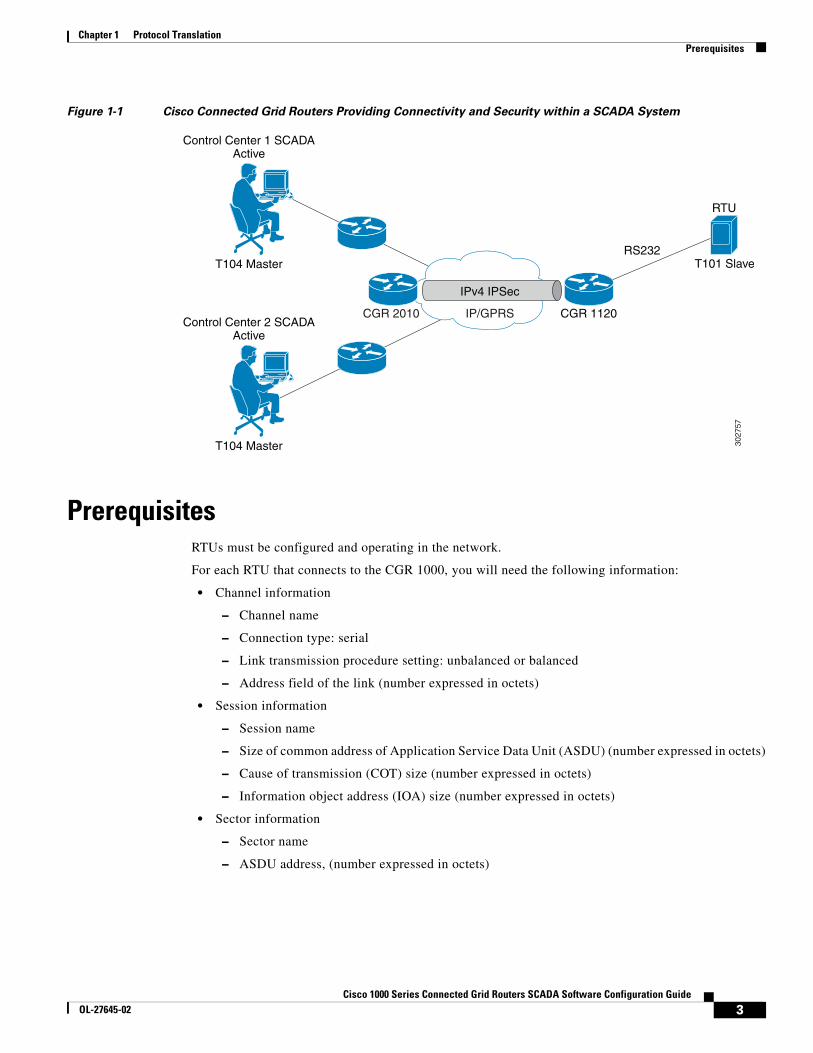
Protocol Translation ApplicationIn Figure 1-1, the CGR 1120 (installed within a secondary substation of the Utility Network) employs Protocol Translation to provide secure, end-to-end connectivity between Control Centers and RTUs within a SCADA System.
The CGR 1120 connects to the RTU (slave) through a RS232 connection. The CGR 1120 securely forwards SCADA data from the RTU to the Control Center in the SCADA system through an IPSec tunnel. You can terminate the IPSec tunnel on either a Cisco 2010 Connected Grid Router (CGR 2010) or a head-end router (such as the Cisco ASR 1000). However, only the CGR 2010 inspects the SCADA traffic before it forwards the traffic to the proper Control Center.
2Cisco 1000 Series Connected Grid Routers SCADA Software Configuration Guide
OL-27645-02
Chapter 1 Protocol TranslationPrerequisites
Figure 1-1 Cisco Connected Grid Routers Providing Connectivity and Security within a SCADA System
PrerequisitesRTUs must be configured and operating in the network.
For each RTU that connects to the CGR 1000, you will need the following information:
• Channel information
– Channel name
– Connection type: serial
– Link transmission procedure setting: unbalanced or balanced
– Address field of the link (number expressed in octets)
• Session information
– Session name
– Size of common address of Application Service Data Unit (ASDU) (number expressed in octets)
– Cause of transmission (COT) size (number expressed in octets)
– Information object address (IOA) size (number expressed in octets)
• Sector information
– Sector name
– ASDU address, (number expressed in octets)
3027
57
IP/GPRS
RTU
CGR 1120
RS232
Control Center 1 SCADAActive
T104 Master T101 Slave
Control Center 2 SCADAActive
T104 Master
CGR 2010
IPv4 IPSec
3Cisco 1000 Series Connected Grid Routers SCADA Software Configuration Guide
OL-27645-02
Chapter 1 Protocol TranslationGuidelines and Limitations
Guidelines and LimitationsEach channel supports only one session.
Each sessions supports only one sector.
Default Settings
Configuring Protocol TranslationThis section includes the following topics:
• Enabling the CGR 1000 Serial Port and T101 Encapsulation, page 1-4
• Enabling Protocol Translation, page 1-5
• Configuring T101 and T104 Protocol Stacks, page 1-5
Enabling the CGR 1000 Serial Port and T101 EncapsulationBefore you can enable and configure Protocol Translation on the CGR 1000, you must first enable the serial port on the CGR 1000 and enable T101 encapsulation on that port.
BEFORE YOU BEGIN
Determine availability of serial port on the Cisco CG-OS router.
DETAILED STEPS
Parameters Default
Role for T101 Master
Role for T104 Slave
Command Purpose
Step 1 configure terminal Enters the global configuration mode.
Step 2 interface serial slot/port Enters the interface command mode for the serial slot/port.
Note The slot/port configuration for the serial port can be 1/1 or 1/2.
Step 3 no shutdown Brings up the port, administratively.
Step 4 encapsulation t101 Enables encapsulation on the serial port for the T101 protocol.
4Cisco 1000 Series Connected Grid Routers SCADA Software Configuration Guide
OL-27645-02
Chapter 1 Protocol TranslationConfiguring Protocol Translation
EXAMPLE
This example shows how to enable serial port 1/1 and how to enable encapsulation on that port to support T101 communication.
router# configure terminal router(config)# interface serial 1/1router (config-if)# no shutdownrouter (config-if)# encapsulation t101
Enabling Protocol TranslationTo enable the CGR 1000 to act as a SCADA Gateway, you must enable the Protocol Translation feature on the router.
BEFORE YOU BEGIN
Enable the serial port on the router and T101 encapsulation on that serial port.
See Enabling the CGR 1000 Serial Port and T101 Encapsulation.
DETAILED STEPS
EXAMPLE
This example shows how to enable the Protocol Translation feature on the CGR 1000 to allow it to operate as a SCADA gateway for RTUs and Control Centers.
router# configure terminal router(config)# feature scada-gwrouter(config)#
Configuring T101 and T104 Protocol StacksAfter enabling Protocol Translation feature on the CGR 1000, you must configure the T101 and T104 protocol stacks, which allow end-to-end communication between Control Centers (T104) and RTUs (T101) within a SCADA system.
• Configuring the T101 Protocol Stack
• Configuring the T104 Protocol Stack, page 1-8
• Starting the Protocol Translation Engine, page 1-10
BEFORE YOU BEGIN
Ensure that you have gathered all the required configuration information. See Prerequisites.
Enable Protocol Translation. See Enabling Protocol Translation.
Command Purpose
Step 1 configure terminal Enters global configuration mode.
Step 2 feature scada-gw Enables the Protocol Translation feature on the CGR 1000.
5Cisco 1000 Series Connected Grid Routers SCADA Software Configuration Guide
OL-27645-02
Chapter 1 Protocol TranslationConfiguring Protocol Translation
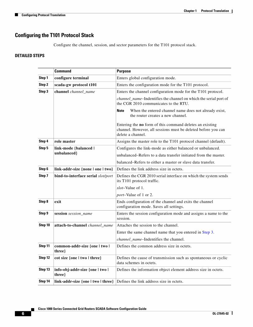
Configuring the T101 Protocol Stack
Configure the channel, session, and sector parameters for the T101 protocol stack.
DETAILED STEPS
Command Purpose
Step 1 configure terminal Enters global configuration mode.
Step 2 scada-gw protocol t101 Enters the configuration mode for the T101 protocol.
Step 3 channel channel_name Enters the channel configuration mode for the T101 protocol.
channel_name–Indentifies the channel on which the serial port of the CGR 2010 communicates to the RTU.
Note When the entered channel name does not already exist, the router creates a new channel.
Entering the no form of this command deletes an existing channel. However, all sessions must be deleted before you can delete a channel.
Step 4 role master Assigns the master role to the T101 protocol channel (default).
Step 5 link-mode {balanced | unbalanced}
Configures the link-mode as either balanced or unbalanced.
unbalanced–Refers to a data transfer initiated from the master.
balanced–Refers to either a master or slave data transfer.
Step 6 link-addr-size {none | one | two} Defines the link address size in octets.
Step 7 bind-to-interface serial slot/port Defines the CGR 2010 serial interface on which the system sends its T101 protocol traffic.
slot–Value of 1.
port–Value of 1 or 2.
Step 8 exit Ends configuration of the channel and exits the channel configuration mode. Saves all settings.
Step 9 session session_name Enters the session configuration mode and assigns a name to the session.
Step 10 attach-to-channel channel_name Attaches the session to the channel.
Enter the same channel name that you entered in Step 3.
channel_name–Indentifies the channel.
Step 11 common-addr-size {one | two | three}
Defines the common address size in octets.
Step 12 cot size {one | two | three} Defines the cause of transmission such as spontaneous or cyclic data schemes in octets.
Step 13 info-obj-addr-size {one | two | three}
Defines the information object element address size in octets.
Step 14 link-addr-size {one | two | three} Defines the link address size in octets.
6Cisco 1000 Series Connected Grid Routers SCADA Software Configuration Guide
OL-27645-02
Chapter 1 Protocol TranslationConfiguring Protocol Translation
EXAMPLE
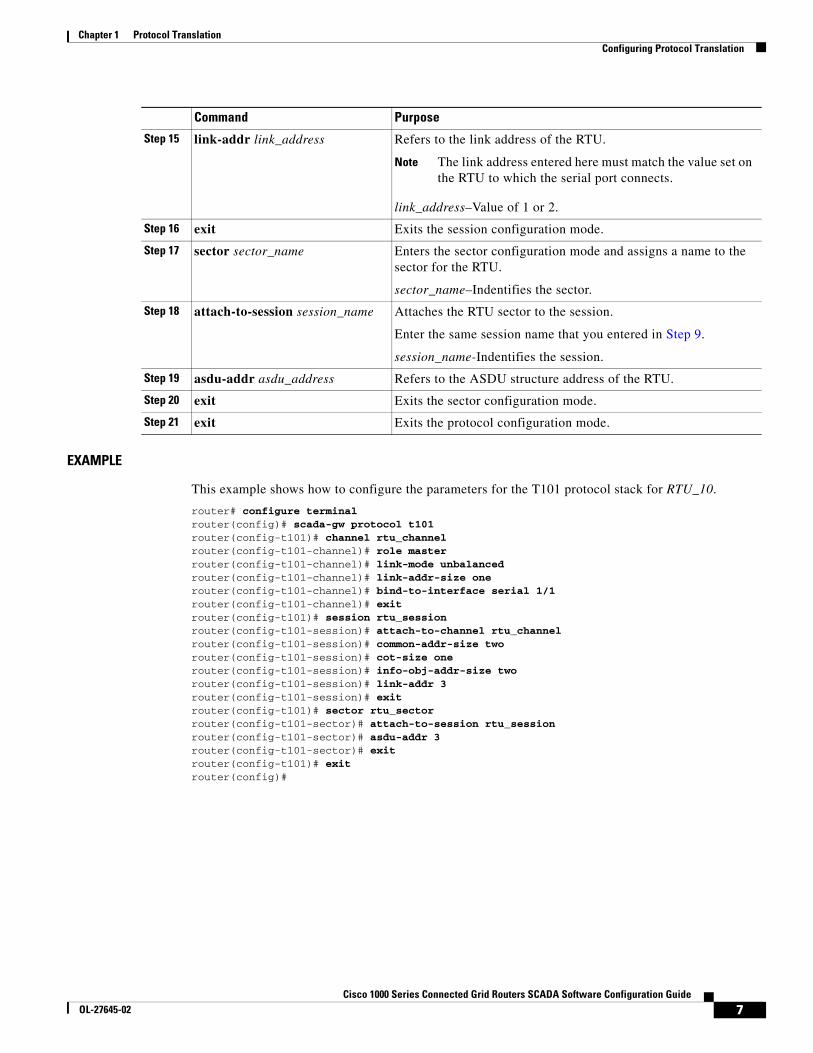
This example shows how to configure the parameters for the T101 protocol stack for RTU_10.
router# configure terminal router(config)# scada-gw protocol t101router(config-t101)# channel rtu_channelrouter(config-t101-channel)# role masterrouter(config-t101-channel)# link-mode unbalancedrouter(config-t101-channel)# link-addr-size onerouter(config-t101-channel)# bind-to-interface serial 1/1router(config-t101-channel)# exitrouter(config-t101)# session rtu_sessionrouter(config-t101-session)# attach-to-channel rtu_channelrouter(config-t101-session)# common-addr-size tworouter(config-t101-session)# cot-size onerouter(config-t101-session)# info-obj-addr-size tworouter(config-t101-session)# link-addr 3router(config-t101-session)# exitrouter(config-t101)# sector rtu_sectorrouter(config-t101-sector)# attach-to-session rtu_sessionrouter(config-t101-sector)# asdu-addr 3router(config-t101-sector)# exitrouter(config-t101)# exitrouter(config)#
Step 15 link-addr link_address Refers to the link address of the RTU.
Note The link address entered here must match the value set on the RTU to which the serial port connects.
link_address–Value of 1 or 2.
Step 16 exit Exits the session configuration mode.
Step 17 sector sector_name Enters the sector configuration mode and assigns a name to the sector for the RTU.
sector_name–Indentifies the sector.
Step 18 attach-to-session session_name Attaches the RTU sector to the session.
Enter the same session name that you entered in Step 9.
session_name-Indentifies the session.
Step 19 asdu-addr asdu_address Refers to the ASDU structure address of the RTU.
Step 20 exit Exits the sector configuration mode.
Step 21 exit Exits the protocol configuration mode.
Command Purpose
7Cisco 1000 Series Connected Grid Routers SCADA Software Configuration Guide
OL-27645-02
Chapter 1 Protocol TranslationConfiguring Protocol Translation
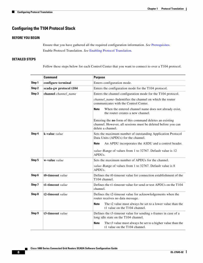
Configuring the T104 Protocol Stack
BEFORE YOU BEGIN
Ensure that you have gathered all the required configuration information. See Prerequisites.
Enable Protocol Translation. See Enabling Protocol Translation.
DETAILED STEPS
Follow these steps below for each Control Center that you want to connect to over a T104 protocol.
Command Purpose
Step 1 configure terminal Enters configuration mode.
Step 2 scada-gw protocol t104 Enters the configuration mode for the T104 protocol.
Step 3 channel channel_name Enters the channel configuration mode for the T104 protocol.
channel_name–Indentifies the channel on which the router communicates with the Control Center.
Note When the entered channel name does not already exist, the router creates a new channel.
Entering the no form of this command deletes an existing channel. However, all sessions must be deleted before you can delete a channel.
Step 4 k-value value Sets the maximum number of outstanding Application Protocol Data Units (APDUs) for the channel.
Note An APDU incorporates the ASDU and a control header.
value–Range of values from 1 to 32767. Default value is 12 APDUs.
Step 5 w-value value Sets the maximum number of APDUs for the channel.
value–Range of values from 1 to 32767. Default value is 8 APDUs.
Step 6 t0-timeout value Defines the t0-timeout value for connection establishment of the T104 channel.
Step 7 t1-timeout value Defines the t1-timeout value for send or test APDUs on the T104 channel.
Step 8 t2-timeout value Defines the t2-timeout value for acknowledgements when the router receives no data message.
Note The t2 value must always be set to a lower value than the t1 value on the T104 channel.
Step 9 t3-timeout value Defines the t3-timeout value for sending s-frames in case of a long idle state on the T104 channel.
Note The t3 value must always be set to a higher value than the t1 value on the T104 channel.
8Cisco 1000 Series Connected Grid Routers SCADA Software Configuration Guide
OL-27645-02
Chapter 1 Protocol TranslationConfiguring Protocol Translation
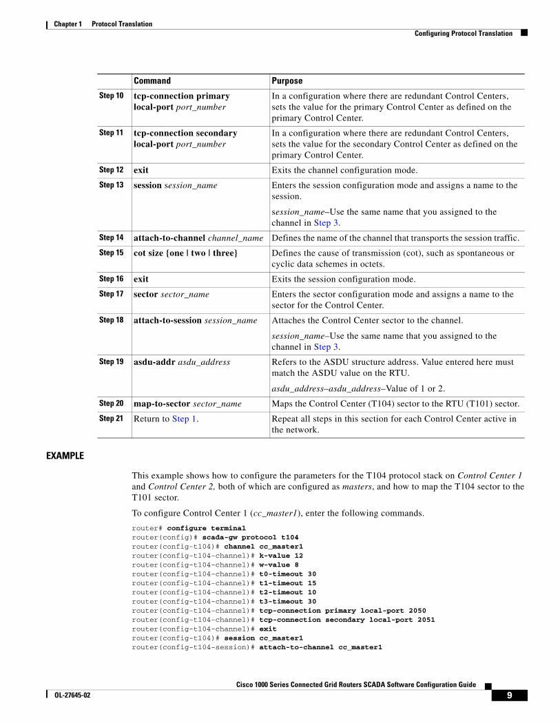
EXAMPLE
This example shows how to configure the parameters for the T104 protocol stack on Control Center 1 and Control Center 2, both of which are configured as masters, and how to map the T104 sector to the T101 sector.
To configure Control Center 1 (cc_master1), enter the following commands.
router# configure terminal router(config)# scada-gw protocol t104router(config-t104)# channel cc_master1router(config-t104-channel)# k-value 12router(config-t104-channel)# w-value 8router(config-t104-channel)# t0-timeout 30router(config-t104-channel)# t1-timeout 15router(config-t104-channel)# t2-timeout 10router(config-t104-channel)# t3-timeout 30router(config-t104-channel)# tcp-connection primary local-port 2050router(config-t104-channel)# tcp-connection secondary local-port 2051router(config-t104-channel)# exitrouter(config-t104)# session cc_master1router(config-t104-session)# attach-to-channel cc_master1
Step 10 tcp-connection primary local-port port_number
In a configuration where there are redundant Control Centers, sets the value for the primary Control Center as defined on the primary Control Center.
Step 11 tcp-connection secondary local-port port_number
In a configuration where there are redundant Control Centers, sets the value for the secondary Control Center as defined on the primary Control Center.
Step 12 exit Exits the channel configuration mode.
Step 13 session session_name Enters the session configuration mode and assigns a name to the session.
session_name–Use the same name that you assigned to the channel in Step 3.
Step 14 attach-to-channel channel_name Defines the name of the channel that transports the session traffic.
Step 15 cot size {one | two | three} Defines the cause of transmission (cot), such as spontaneous or cyclic data schemes in octets.
Step 16 exit Exits the session configuration mode.
Step 17 sector sector_name Enters the sector configuration mode and assigns a name to the sector for the Control Center.
Step 18 attach-to-session session_name Attaches the Control Center sector to the channel.
session_name–Use the same name that you assigned to the channel in Step 3.
Step 19 asdu-addr asdu_address Refers to the ASDU structure address. Value entered here must match the ASDU value on the RTU.
asdu_address–asdu_address–Value of 1 or 2.
Step 20 map-to-sector sector_name Maps the Control Center (T104) sector to the RTU (T101) sector.
Step 21 Return to Step 1. Repeat all steps in this section for each Control Center active in the network.
Command Purpose
9Cisco 1000 Series Connected Grid Routers SCADA Software Configuration Guide
OL-27645-02
Chapter 1 Protocol TranslationConfiguring Protocol Translation
router(config-t104-session)# cot-size tworouter(config-t104-session)# exitrouter(config-t104)# sector cc_master1-sectorrouter(config-t104-sector)# attach-to-session cc_master1router(config-t104-sector)# asdu-adr 3router(config-t104-sector)# map-to-sector rtu_sectorrouter(config-t104)# exitrouter(config)#
To configure Control Center 2 (cc_master2), enter the following commands.
router(config)# scada-gw protocol t104router(config-t104)# channel cc_master2router(config-t104-channel)# k-value 12router(config-t104-channel)# w-value 8router(config-t104-channel)# t0-timeout 30router(config-t104-channel)# t1-timeout 15router(config-t104-channel)# t2-timeout 10router(config-t104-channel)# t3-timeout 30router(config-t104-channel)# tcp-connection primary local-port 2060router(config-t104-channel)# tcp-connection secondary local-port 2061router(config-t104-channel)# exitrouter(config-t104)# session cc_master2router(config-t104-session)# attach-to-channel cc_master2router(config-t104-session)# cot-size tworouter(config-t104-session)# exitrouter(config-t104)# sector cc_master2-sectorrouter(config-t104-sector)# attach-to-session cc_master2router(config-t104-sector)# asdu-adr 3router(config-t104-sector)# map-to-sector rtu_sectorrouter(config-t104-sector)# exitrouter(config-t104)# exitrouter(config)#
Starting the Protocol Translation Engine
BEFORE YOU BEGIN
After configuring the T101 and T104 protocols on the CGR 1000, you can start the Protocol Translation Engine.
DETAILED STEPS
router# configure terminalrouter(config)# scada-gw enable
Command Purpose
Step 1 configure terminal Enters global configuration mode.
Step 2 scada-gw enable Starts the Protocol Translation Engine on the CGR 1000.
10Cisco 1000 Series Connected Grid Routers SCADA Software Configuration Guide
OL-27645-02

Chapter 1 Protocol TranslationVerifying Configuration
Verifying Configuration
Configuration ExampleThe following example shows how to configure the serial port interface for T101 connection, configure T101 and T104 protocol stacks, and starts the Protocol Translation Engine on the CGR 1000.
router# configure terminal router(config)# interface serial 1/1router (config-if)# no shutdownrouter (config-if)# encapsulation 101router (config-if)# exitrouter(config)# scada-gw protocol t101router(config-t101)# channel rtu_channelrouter(config-t101-channel)# role masterrouter(config-t101-channel)# link-mode unbalancedrouter(config-t101-channel)# link-addr-size onerouter(config-t101-channel)# bind-to-interface serial 1/1router(config-t101-channel)# exitrouter(config-t101)# session rtu_sessionrouter(config-t101-session)# attach-to-channel rtu_channelrouter(config-t101-session)# common-addr-size tworouter(config-t101-session)# cot-size onerouter(config-t101-session)# info-obj-addr-size tworouter(config-t101-session)# link-addr 3router(config-t101-session)# exitrouter(config-t101)# sector rtu_sectorrouter(config-t101-sector)# attach-to-session rtu_sessionrouter(config-t101-sector)# asdu-addr 3router(config-t101-sector)# exitrouter(config-t101)# exitrouter(config)# scada-gw protocol t104router(config-t104)# channel cc_master1router(config-t104-channel)# k-value 12router(config-t104-channel)# w-value 8router(config-t104-channel)# t0-timeout 30router(config-t104-channel)# t1-timeout 15router(config-t104-channel)# t2-timeout 10router(config-t104-channel)# t3-timeout 30router(config-t104-channel)# tcp-connection primary local-port 2050router(config-t104-channel)# tcp-connection secondary local-port 2051router(config-t104-channel)# exitrouter(config-t104)# session cc_master1router(config-t104-session)# attach-to-channel cc_master1router(config-t104-session)# cot-size tworouter(config-t104-session)# exitrouter(config-t104)# sector cc_master1-sectorrouter(config-t104-sector)# attach-to-session cc_master1router(config-t104-sector)# asdu-adr 3router(config-t104-sector)# map-to-sector rtu_sectorrouter(config-t104)# exitrouter(config)# scada-gw protocol t104router(config-t104)# channel cc_master2
Command Purpose
show running-config Shows the configuration of the router including those features that are active and their settings.
11Cisco 1000 Series Connected Grid Routers SCADA Software Configuration Guide
OL-27645-02
Chapter 1 Protocol TranslationFeature History
router(config-t104-channel)# k-value 12router(config-t104-channel)# w-value 8router(config-t104-channel)# t0-timeout 30router(config-t104-channel)# t1-timeout 15router(config-t104-channel)# t2-timeout 10router(config-t104-channel)# t3-timeout 30router(config-t104-channel)# tcp-connection primary local-port 2060router(config-t104-channel)# tcp-connection secondary local-port 2061router(config-t104-channel)# exitrouter(config-t104)# session cc_master2router(config-t104-session)# attach-to-channel cc_master2router(config-t104-session)# cot-size tworouter(config-t104-session)# exitrouter(config-t104)# sector cc_master2-sectorrouter(config-t104-sector)# attach-to-session cc_master2router(config-t104-sector)# asdu-adr 3router(config-t104-sector)# map-to-sector rtu_sectorrouter(config-t104-sector)# exitrouter(config-t104)# exitrouter(config)# scada-gw enable
Feature History
Feature Name Release Feature Information
Protocol translation Cisco CG-OS Release CG2(1) Initial support of the feature on the CGR 1000 Series Routers.
12Cisco 1000 Series Connected Grid Routers SCADA Software Configuration Guide
OL-27645-02
Cisco 1000 Series ConnectedOL-27645-02
C H A P T E R 2
Configuring PPPThis chapter describes how to configure the Point-to-Point Protocol (PPP) on serial ports on Cisco 1000 Series Connected Grid Routers (hereafter referred to as the Cisco CG-OS router or CGR 1000).
PPP over the serial port provides IP connectivity to downstream systems within the Supervisory Control and Data Acquisition (SCADA) system.
Additionally, this chapter provides details on enabling and configuring serial ports with either a RS232 DCE or RS485 interface.
This chapter includes the following sections:
• Information About PPP, page 2-1
• Prerequisites, page 2-2
• Guidelines and Limitations, page 2-2
• Default Settings, page 2-3
• Enabling the CGR 1000 Serial Port, page 2-3
• Configuring the Line Parameters, page 2-5
• Enabling PPP, page 2-6
• Configuring PPP, page 2-7
• Verifying Configuration, page 2-8
• Configuration Examples, page 2-9
• Feature History, page 2-9
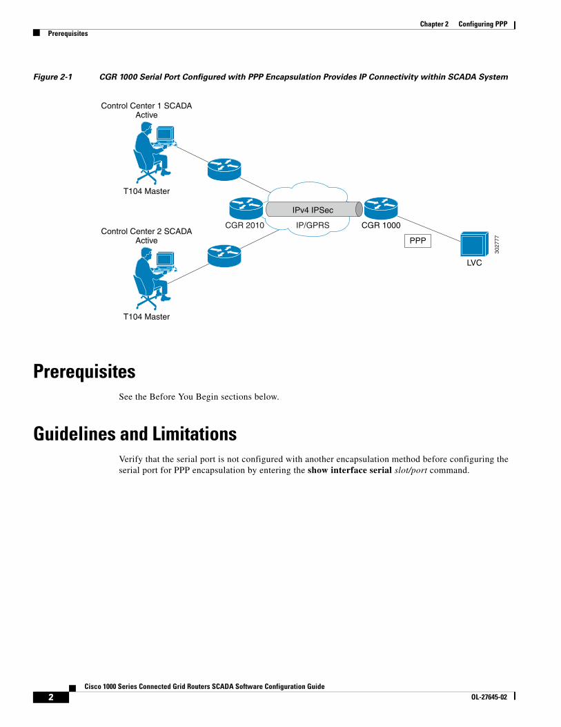
Information About PPPPPP over the serial port provides IP connectivity to downstream systems within the SCADA system.
Figure 2-1 provides an example in which you enable the serial port on a CGR 1000 and configure PPP encapsulation on that port to provide connectivity to a low voltage concentrator (LVC). Data from the LVC is then transmitted over a secure IPSec tunnel network to a Control Center for processing.
Challenge Handshake Authentication Protocol (CHAP) provides authentication for communications between the LVC and the CGR 1000. With CHAP, the secret must be in plaintext form. However, the router also supports encrypted passwords.
1 Grid Routers SCADA Software Configuration Guide
Chapter 2 Configuring PPPPrerequisites
Figure 2-1 CGR 1000 Serial Port Configured with PPP Encapsulation Provides IP Connectivity within SCADA System
PrerequisitesSee the Before You Begin sections below.
Guidelines and LimitationsVerify that the serial port is not configured with another encapsulation method before configuring the serial port for PPP encapsulation by entering the show interface serial slot/port command.
3027
77
IP/GPRS
LVC
PPP
CGR 1000
Control Center 1 SCADAActive
T104 Master
Control Center 2 SCADAActive
T104 Master
CGR 2010
IPv4 IPSec
2Cisco 1000 Series Connected Grid Routers SCADA Software Configuration Guide
OL-27645-02
Chapter 2 Configuring PPPDefault Settings
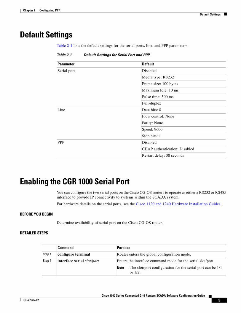
Default SettingsTable 2-1 lists the default settings for the serial ports, line, and PPP parameters.
Enabling the CGR 1000 Serial PortYou can configure the two serial ports on the Cisco CG-OS routers to operate as either a RS232 or RS485 interface to provide IP connectivity to systems within the SCADA system.
For hardware details on the serial ports, see the Cisco 1120 and 1240 Hardware Installation Guides.
BEFORE YOU BEGIN
Determine availability of serial port on the Cisco CG-OS router.
DETAILED STEPS
Table 2-1 Default Settings for Serial Port and PPP
Parameter Default
Serial port Disabled
Media type: RS232
Frame size: 100 bytes
Maximum Idle: 10 ms
Pulse time: 500 ms
Full-duplex
Line Data bits: 8
Flow control: None
Parity: None
Speed: 9600
Stop bits: 1
PPP Disabled
CHAP authentication: Disabled
Restart delay: 30 seconds
Command Purpose
Step 1 configure terminal Router enters the global configuration mode.
Step 1 interface serial slot/port Enters the interface command mode for the serial slot/port.
Note The slot/port configuration for the serial port can be 1/1 or 1/2.
3Cisco 1000 Series Connected Grid Routers SCADA Software Configuration Guide
OL-27645-02
Chapter 2 Configuring PPPEnabling the CGR 1000 Serial Port
EXAMPLE
This example shows how to enable serial port interface 1/1 on the router, define that interface as a RS232 media-type, enable PPP encapsulation on the interface, and add a description.
router# configure terminal router(config)# interface serial 1/1router (config-if)# encapsulation ppprouter (config-if)# media-type RS232router (config-if)# no shutdownrouter (config-if)# description “Adding PPP encapsulation to serial port”
Step 2 description text Provides a textual description of the interface being configured.
text–Allows 80 alphanumeric, case sensitive, characters.
Step 3 ip address ip address mask [secondary]
Specifies a primary or secondary IPv4 address for an interface.
ip address mask–The network mask can be a four-part dotted decimal address. For example, 255.0.0.0 indicates that each bit equal to 1 means the corresponding address bit belongs to the network address.
The network mask can be indicated as a slash (/) and a number (a prefix length). The prefix length is a decimal value that indicates how many of the high-order contiguous bits of the address comprise the prefix (the network portion of the address). A slash must precede the decimal value and there is no space between the IP address and the slash.
Step 4 no shutdown Brings up the port, administratively.
Step 5 media-type {rs232 | rs485} Specifies the media type on the serial port. RS232 is the default.
Step 6 frame-size number Sets the maximum bytes per frame.
number–Values of 1 to 512. Default setting is 100 bytes.
Step 7 max-idle number Sets the gap between frames.
number–Value of 1 to 1000. Default setting is 10 ms.
Step 8 pulse-time number Defines the period of time before the software notifies a connecting system of an up or down state (enabled/disabled) of the serial port or its link.
number–Value of 1 to 3000. Default setting is 500 ms.
Step 9 {full-duplex | half-duplex} Configures the serial port to operate in either full-duplex or half-duplex mode. Default setting is full-duplex.
Step 10 copy running-config startup-config
(Optional) Saves this configuration change.
Command Purpose
4Cisco 1000 Series Connected Grid Routers SCADA Software Configuration Guide
OL-27645-02
Chapter 2 Configuring PPPConfiguring the Line Parameters
Clearing Interface CountersWhen debugging a connection issue, you can use any of all of the following commands to clear the counters.
Configuring the Line ParametersYou can set and modify the line parameters using the Linux TTY application for each of the Cisco serial ports on the CG-OS router.
BEFORE YOU BEGIN
Enable the serial port on the CG-OS router and define the interface as a RS232 or RS485.
See Enabling the CGR 1000 Serial Port.
DETAILED STEPS
Command Purpose
clear counters interface all Clears counters on all interfaces.
clear counters interface serial slot/port Clears all interface counters for a specified interface.
Command Purpose
Step 1 configure terminal Router enters the global configuration mode.
Step 1 line tty {1 | 2} Enter this command at the global configuration mode to modify line settings.
1–Configures the line for serial port 1/1
2–Configures the line for serial port 1/2
Step 2 [no] databits Defines the number of data bits per character.
number–Values are 5 to 8. Default values is 8.
The no form of the command disables the function.
Step 3 [no] flowcontrol {hardware | none}
Enables or disables the use of flow control on the line.
hardware–Enables CTS and RTS as the flow control mechanism.
none–Select this option when the configuration does not want or require flow control.
The no form of the command disables the function.
Note Setting must match that of the peer.
Step 4 [no] parity {even | odd | none} Sets or disables the terminal parity.
Note Setting must match that of the peer
5Cisco 1000 Series Connected Grid Routers SCADA Software Configuration Guide
OL-27645-02
Chapter 2 Configuring PPPEnabling PPP
EXAMPLE
This example shows how to configure line settings on serial port 1/2.
router# configure terminal router(config)# line tty 1router (config-line)# flowcontrol nonerouter (config-line)# parity evenrouter (config-line)# speed 56000
Enabling PPPYou must enable the PPP feature on the Cisco CG-OS router. It is not enabled by default.
DETAILED STEPS
EXAMPLE
This example shows how to enable PPP on the CG-OS router.
router# configure terminal router(config)# feature ppp
Step 5 [no] speed value Sets the transmit and receive speeds for the line.
Value–Any value between 300 and 115200 baud rate. Default value is 9600.
The no form of the command removes the setting.
Note Setting must match that of the peer.
Step 6 [no] stopbits {1 | 2} Defines the asynchronous line stop bits. Default value is 1.
Note When you set the stop bits for a value of 2 and the data bits for a value of 5, the stop bits setting becomes 1.5
Step 7 [no] location string Specifies the location of the router.
string–Up to 240 bytes.
Command Purpose
Command Purpose
Step 1 configure terminal Enters the global configuration mode.
Step 2 feature ppp Enables the PPP feature.
6Cisco 1000 Series Connected Grid Routers SCADA Software Configuration Guide
OL-27645-02
Chapter 2 Configuring PPPConfiguring PPP
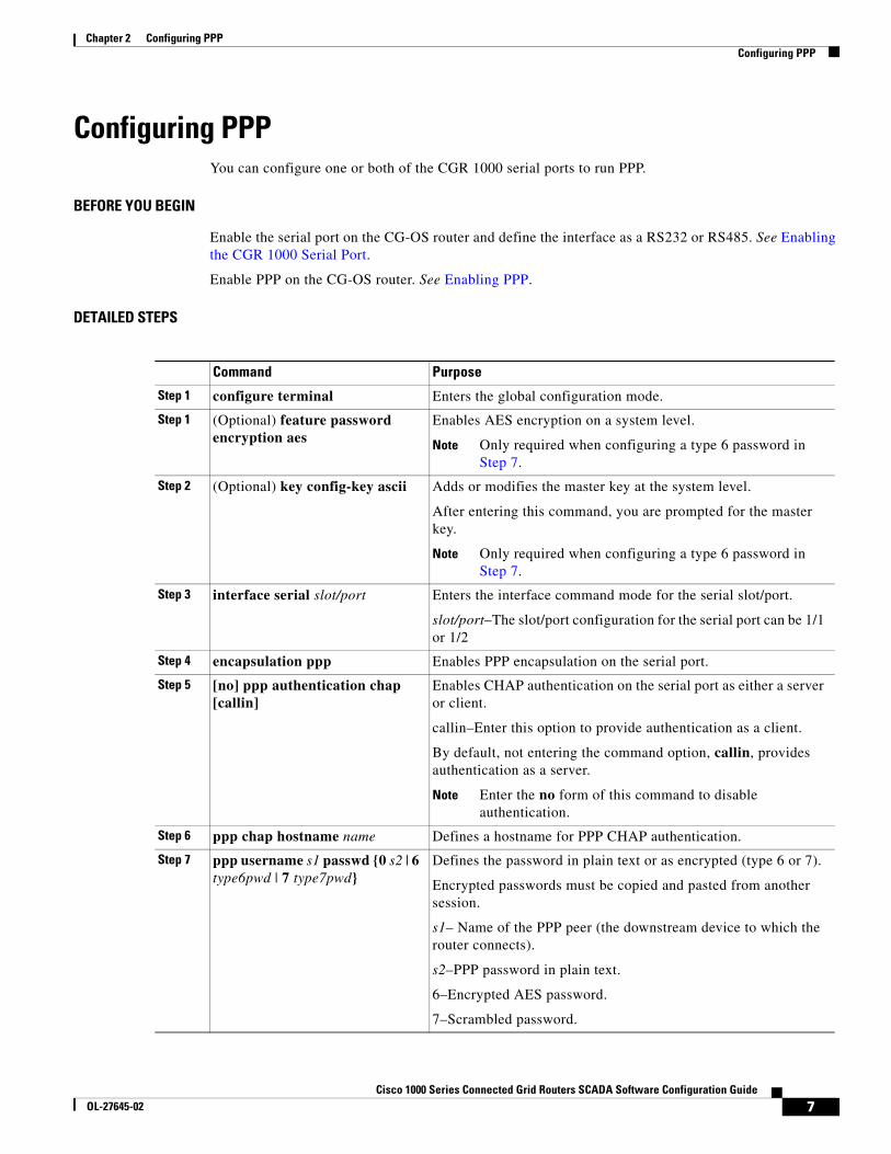
Configuring PPPYou can configure one or both of the CGR 1000 serial ports to run PPP.
BEFORE YOU BEGIN
Enable the serial port on the CG-OS router and define the interface as a RS232 or RS485. See Enabling the CGR 1000 Serial Port.
Enable PPP on the CG-OS router. See Enabling PPP.
DETAILED STEPS
Command Purpose
Step 1 configure terminal Enters the global configuration mode.
Step 1 (Optional) feature password encryption aes
Enables AES encryption on a system level.
Note Only required when configuring a type 6 password in Step 7.
Step 2 (Optional) key config-key ascii Adds or modifies the master key at the system level.
After entering this command, you are prompted for the master key.
Note Only required when configuring a type 6 password in Step 7.
Step 3 interface serial slot/port Enters the interface command mode for the serial slot/port.
slot/port–The slot/port configuration for the serial port can be 1/1 or 1/2
Step 4 encapsulation ppp Enables PPP encapsulation on the serial port.
Step 5 [no] ppp authentication chap [callin]
Enables CHAP authentication on the serial port as either a server or client.
callin–Enter this option to provide authentication as a client.
By default, not entering the command option, callin, provides authentication as a server.
Note Enter the no form of this command to disable authentication.
Step 6 ppp chap hostname name Defines a hostname for PPP CHAP authentication.
Step 7 ppp username s1 passwd {0 s2 | 6 type6pwd | 7 type7pwd}
Defines the password in plain text or as encrypted (type 6 or 7).
Encrypted passwords must be copied and pasted from another session.
s1– Name of the PPP peer (the downstream device to which the router connects).
s2–PPP password in plain text.
6–Encrypted AES password.
7–Scrambled password.
7Cisco 1000 Series Connected Grid Routers SCADA Software Configuration Guide
OL-27645-02
Chapter 2 Configuring PPPVerifying Configuration
EXAMPLE
This example shows how to configure PPP (as a server) with encrypted authentication of type 6 on the enabled serial port 1/1.
router# configure terminal router(config)# interface serial 1/1router(config-if)# encapuslation ppprouter(config-if)# ppp authentication chap callinrouter(config-if)# ppp chap hostname cgr1120router(config-if)# ppp username lcv-va07 passwd 0 secretword
Verifying ConfigurationTo display PPP or serial port configuration information, perform one of the following tasks.
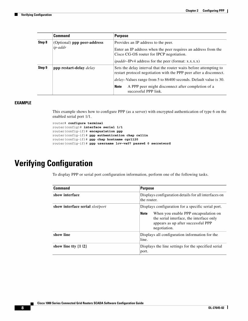
Step 8 (Optional) ppp peer-address ip-addr
Provides an IP address to the peer.
Enter an IP address when the peer requires an address from the Cisco CG-OS router for IPCP negotiation.
ipaddr–IPv4 address for the peer (format: x.x.x.x)
Step 9 ppp restart-delay delay Sets the delay interval that the router waits before attempting to restart protocol negotiation with the PPP peer after a disconnect.
delay–Values range from 5 to 86400 seconds. Default value is 30.
Note A PPP peer might disconnect after completion of a successful PPP link.
Command Purpose
Command Purpose
show interface Displays configuration details for all interfaces on the router.
show interface serial slot/port Displays configuration for a specific serial port.
Note When you enable PPP encapsulation on the serial interface, the interface only appears as up after successful PPP negotiation.
show line Displays all configuration information for the line.
show line tty {1 |2} Displays the line settings for the specified serial port.
8Cisco 1000 Series Connected Grid Routers SCADA Software Configuration Guide
OL-27645-02
Chapter 2 Configuring PPPConfiguration Examples
Configuration Examplesrouter# configure terminal router(config)# interface serial 1/1router(config-if)# media-type RS232router(config-if)# no shutdownrouter(config-if)# exitrouter(config)# line tty 1router (config-line)# flowcontrol nonerouter (config-line)# parity evenrouter (config-line)# speed 56000router (config-line)# exitrouter (config)# exitrouter (config-if)# description “Adding PPP encapsulation to serial port”router(config-if)# encapuslation ppprouter(config-if)# ppp authentication chap callinrouter(config-if)# ppp chap hostname cgr1120router(config-if)# ppp username lcv-va07 passwd 0 secretwordrouter (config-if)# copy running-config startup-config
Feature History
Feature Name Release Feature Information
Active serial ports on CGR 1000 routers.
Cisco CG-OS Release CG2(1) Initial support of the feature on the CGR 1000 Series Routers.
PPP over serial ports.
9Cisco 1000 Series Connected Grid Routers SCADA Software Configuration Guide
OL-27645-02

Chapter 2 Configuring PPPFeature History
10Cisco 1000 Series Connected Grid Routers SCADA Software Configuration Guide
OL-27645-02
Cisco 1000 Series ConnectedOL-27645-02
C H A P T E R 3
Raw Socket TransportThe Raw Socket Transport feature provides a method for placing serial data into packets and transferring the data across an IP network, using TCP connections between Cisco Connected Grid Routers (Cisco CG-OS routers or CGRs).
This chapter describes how to configure Raw Socket Transport on the Cisco Series 1000 Connected Grid Router (CGR 1000). The feature is also supported on the Cisco 2010 Connected Grid Router (CGR 2010); for more information, see Configuring Raw Socket Protocol on the CGR 2010 Router.
This chapter includes the following sections:
• Information About Raw Socket Transport, page 3-1
• Prerequisites, page 3-2
• Configuring Raw Socket Transport, page 3-2
• Configuration Example, page 3-6
• Feature History, page 3-7
Information About Raw Socket TransportRaw Socket is a method for transporting serial data through an IP network. The feature can be used to transport Supervisory Control and Data Acquisition (SCADA) data from Remote Terminal Units (RTUs). This method is an alternative to the Block Serial Tunnel (BSTUN) protocol.
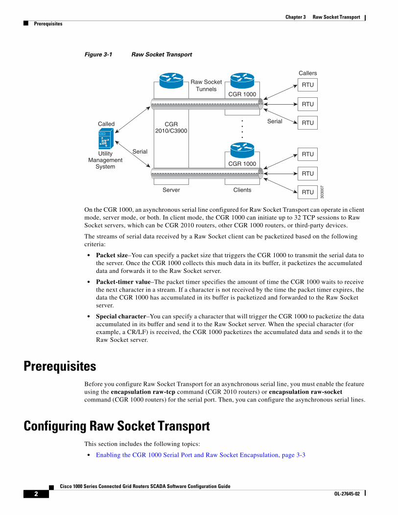
Figure 3-1 shows a sample Raw Socket configuration. In this example, serial data is transferred between RTUs and a utility management system across an IP network that includes a single CGR 2010 router and several CGR 1000 routers. The CGR 2010 router acts as a Raw Socket server, listening for TCP connection requests from the CGR 1000 routers, which are configured as Raw Socket clients.
A Raw Socket client receives streams of serial data from the RTUs and accumulates this data in its buffer, then places the data into packets, based on user-specified packetization criteria. The Raw Socket client initiates a TCP connection with the Raw Socket server and sends the packetized data across the IP network to the Raw Socket server, which retrieves the serial data from the packets and sends it to the serial interface, and on to the utility management system.
1 Grid Routers SCADA Software Configuration Guide
Chapter 3 Raw Socket TransportPrerequisites
Figure 3-1 Raw Socket Transport
On the CGR 1000, an asynchronous serial line configured for Raw Socket Transport can operate in client mode, server mode, or both. In client mode, the CGR 1000 can initiate up to 32 TCP sessions to Raw Socket servers, which can be CGR 2010 routers, other CGR 1000 routers, or third-party devices.
The streams of serial data received by a Raw Socket client can be packetized based on the following criteria:
• Packet size–You can specify a packet size that triggers the CGR 1000 to transmit the serial data to the server. Once the CGR 1000 collects this much data in its buffer, it packetizes the accumulated data and forwards it to the Raw Socket server.
• Packet-timer value–The packet timer specifies the amount of time the CGR 1000 waits to receive the next character in a stream. If a character is not received by the time the packet timer expires, the data the CGR 1000 has accumulated in its buffer is packetized and forwarded to the Raw Socket server.
• Special character–You can specify a character that will trigger the CGR 1000 to packetize the data accumulated in its buffer and send it to the Raw Socket server. When the special character (for example, a CR/LF) is received, the CGR 1000 packetizes the accumulated data and sends it to the Raw Socket server.
PrerequisitesBefore you configure Raw Socket Transport for an asynchronous serial line, you must enable the feature using the encapsulation raw-tcp command (CGR 2010 routers) or encapsulation raw-socket command (CGR 1000 routers) for the serial port. Then, you can configure the asynchronous serial lines.
Configuring Raw Socket TransportThis section includes the following topics:
• Enabling the CGR 1000 Serial Port and Raw Socket Encapsulation, page 3-3
CGR 1000
CGR 1000
Serial
Raw Socket Tunnels
Serial RTU
Callers
Called
RTU
RTU
ClientsServer
3030
07
UtilityManagement
System
CGR2010/C3900
RTU
RTU
RTU
2Cisco 1000 Series Connected Grid Routers SCADA Software Configuration Guide
OL-27645-02
Chapter 3 Raw Socket TransportConfiguring Raw Socket Transport
• Configuring an Asynchronous Serial Line for Raw Socket Transport, page 3-3
Enabling the CGR 1000 Serial Port and Raw Socket EncapsulationTo enable the Raw Socket feature on the CGR 1000 router, you must first enable a serial port and enable Raw Socket encapsulation for that port.
BEFORE YOU BEGIN
Determine availability of the serial port on the CGR 1000 router.
DETAILED STEPS
EXAMPLE
This example shows how to enable serial port 1/1 and how to enable Raw Socket encapsulation on that port.
router# configure terminal router(config)# interface serial 1/1router(config-if)# no shutdownrouter(config-if)# encapsulation raw-socketrouter(config-if)# exitrouter(config)#
Configuring an Asynchronous Serial Line for Raw Socket TransportAfter enabling Raw Socket encapsulation for a serial port, you specify Raw Socket settings for an asynchronous serial line.
BEFORE YOU BEGIN
Enable a serial port and Raw Socket encapsulation for that port, as described in the previous section.
DETAILED STEPS
Follow the steps below for each asynchronous serial line you are configuring to use Raw Socket Transport.
Command Purpose
Step 1 configure terminal Enters the global configuration mode.
Step 2 interface serial slot/port Enters the interface command mode for the serial slot/port.
Note The slot/port configuration for the serial port can be 1/1 or 1/2.
Step 3 no shutdown Brings up the port, administratively.
Step 4 encapsulation raw-socket Enables Raw Socket encapsulation for the serial port.
3Cisco 1000 Series Connected Grid Routers SCADA Software Configuration Guide
OL-27645-02
Chapter 3 Raw Socket TransportConfiguring Raw Socket Transport
Command Purpose
Step 1 configure terminal Enters configuration mode.
Step 2 line tty 1 | 2 Enters line configuration mode for a standard asynchronous line.
Step 3 raw-socket tcp client dest_ip_address dest_port [local_ip_address] [local_port]
(If configuring as a Raw Socket client) Specifies settings for Raw Socket Transport TCP client sessions.
dest_ip_address–Destination IP address of the remote Raw Socket server.
dest_port–Destination port number to use for the TCP connection to the remote server.
local_ip_address–(Optional) Local IP address that the client can also bind to.
local_port–(Optional) Local port number that the client can also bind to.
Step 4 raw-socket tcp server port [ip_address] (If configuring as a Raw Socket server) Starts the Raw Socket Transport TCP server for an asynchronous line interface. In Raw Socket server mode, the CGR 1000 listens for incoming connection requests from Raw Socket clients.
port–Port number the server listens on.
ip_address–(Optional) Local IP address on which the server listens for connection requests.
Step 5 raw-socket tcp idle-timeout session_timeout Sets the Raw Socket Transport TCP session timeout for the asynchronous line interface. If no data is transferred between the client and server over this interval, then the TCP session is closed. The client then automatically attempts to reestablish the TCP session with the server.
This timeout setting applies to all Raw Socket Transport TCP sessions under this particular line.
session_timeout–Currently configured session idle timeout in minutes. The default is 5 minutes.
Step 6 raw-socket packet-length packet_size Specifies the packet size that triggers the CGR 1000 to transmit the data to the server. When the CGR 1000 accumulates this much data in its buffer, it packetizes the data and forwards it to the Raw Socket server.
packet_size–Packet size in bytes (16–1400). The default is off, meaning that the maximum packet size for the interface is used.
4Cisco 1000 Series Connected Grid Routers SCADA Software Configuration Guide
OL-27645-02
Chapter 3 Raw Socket TransportVerifying Configuration
EXAMPLE
This example shows how to configure the Raw Socket Transport feature for an asynchronous serial line. The CGR 1000 is configured as a Raw Socket client that initiates TCP sessions with two Raw Socket servers and forwards packetized serial data to them. The CGR 1000 collects streams of serial data in its buffer; when it accumulates 827 bytes in its buffer, the CGR 1000 packetizes the data and forwards it to the Raw Socket servers. In the event that no data is exchanged between the CGR 1000 and one of the Raw Socket servers for 10 minutes, then the TCP session with the Raw Socket server is closed, and the CGR 1000 attempts to reestablish the session with the Raw Socket server.
router# configure terminal router(config)# line tty 1router(config-tty)# raw-socket tcp client 10.0.0.1 4000router(config-tty)# raw-socket tcp client 20.0.0.1 4000router(config-tty)# raw-socket packet-length 827router(config-tty)# raw-socket tcp idle-timeout 10router(config-tty)# exitrouter(config)#
Verifying Configuration
Step 7 raw-socket packet-timer packet_timer Specifies the maximum time in milliseconds the CGR 1000 waits to receive the next character in a stream. If a character is not received by the time the packet-timer expires, the accumulated data is packetized and forwarded to the Raw Socket server.
packet_timer–Time in milliseconds. The default is 10 milliseconds.
Step 8 raw-socket special-char special_character Specifies a character that will trigger the CGR 1000 to packetize the data accumulated in its buffer and send it to the Raw Socket server.
When the serial interface receives this special character, the interface packetizes the accumulated bytes into a TCP frame and sends it to the server through the Raw Socket Transport tunnel.
special_character–Character value (0–255). By default, the special character trigger is disabled.
Command Purpose
Command Purpose
show running-config Shows the configuration of the router including those features that are active and their settings.
show raw-socket tcp detail Displays information about Raw Socket Transport TCP activity.
show raw-socket tcp sessions Displays information about Raw Socket Transport TCP sessions.
5Cisco 1000 Series Connected Grid Routers SCADA Software Configuration Guide
OL-27645-02
Chapter 3 Raw Socket TransportConfiguration Example
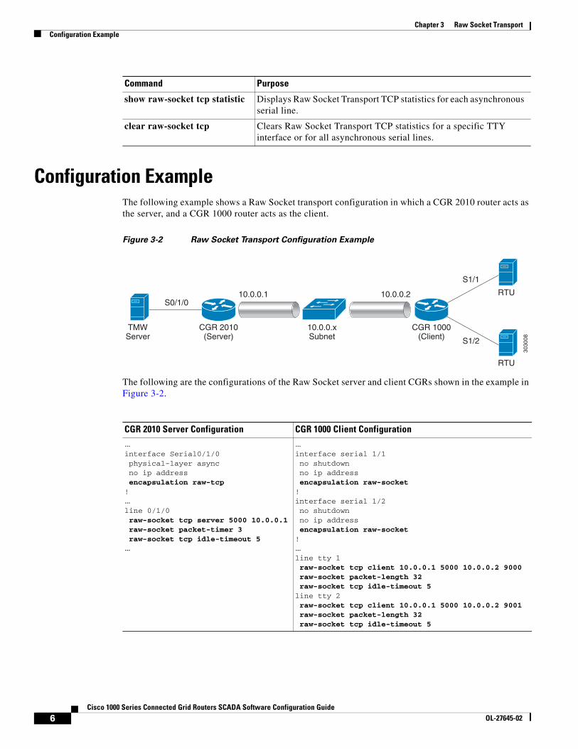
Configuration ExampleThe following example shows a Raw Socket transport configuration in which a CGR 2010 router acts as the server, and a CGR 1000 router acts as the client.
Figure 3-2 Raw Socket Transport Configuration Example
The following are the configurations of the Raw Socket server and client CGRs shown in the example in Figure 3-2.
show raw-socket tcp statistic Displays Raw Socket Transport TCP statistics for each asynchronous serial line.
clear raw-socket tcp Clears Raw Socket Transport TCP statistics for a specific TTY interface or for all asynchronous serial lines.
Command Purpose
CGR 2010(Server)
CGR 1000(Client)
10.0.0.xSubnet
TMWServer
S0/1/010.0.0.1 10.0.0.2
S1/1
S1/2
3030
08
RTU
RTU
CGR 2010 Server Configuration CGR 1000 Client Configuration…interface Serial0/1/0 physical-layer async no ip address encapsulation raw-tcp! …line 0/1/0 raw-socket tcp server 5000 10.0.0.1 raw-socket packet-timer 3 raw-socket tcp idle-timeout 5…
…interface serial 1/1 no shutdown no ip address encapsulation raw-socket! interface serial 1/2 no shutdown no ip address encapsulation raw-socket! …line tty 1 raw-socket tcp client 10.0.0.1 5000 10.0.0.2 9000 raw-socket packet-length 32 raw-socket tcp idle-timeout 5line tty 2 raw-socket tcp client 10.0.0.1 5000 10.0.0.2 9001 raw-socket packet-length 32 raw-socket tcp idle-timeout 5
6Cisco 1000 Series Connected Grid Routers SCADA Software Configuration Guide
OL-27645-02

Chapter 3 Raw Socket TransportFeature History
Feature History
Feature Name Release Feature Information
Raw socket transport Cisco CG-OS Release CG3(1) Initial support of the feature on the CGR 1000 Series Routers.
7Cisco 1000 Series Connected Grid Routers SCADA Software Configuration Guide
OL-27645-02

Chapter 3 Raw Socket TransportFeature History
8Cisco 1000 Series Connected Grid Routers SCADA Software Configuration Guide
OL-27645-02