cisco 819 integrated services router configuration guide
DESCRIPTION
Cisco 819 Integrated Services Router Configuration Guide.TRANSCRIPT

Cisco 819 Series Integrated Services Routers Software Configuration Guide November 2, 2012
Americas HeadquartersCisco Systems, Inc.170 West Tasman DriveSan Jose, CA 95134-1706 USAhttp://www.cisco.comTel: 408 526-4000
800 553-NETS (6387)Fax: 408 527-0883
Text Part Number: OL-23590-02

THE SPECIFICATIONS AND INFORMATION REGARDING THE PRODUCTS IN THIS MANUAL ARE SUBJECT TO CHANGE WITHOUT NOTICE. ALL STATEMENTS, INFORMATION, AND RECOMMENDATIONS IN THIS MANUAL ARE BELIEVED TO BE ACCURATE BUT ARE PRESENTED WITHOUT WARRANTY OF ANY KIND, EXPRESS OR IMPLIED. USERS MUST TAKE FULL RESPONSIBILITY FOR THEIR APPLICATION OF ANY PRODUCTS.
THE SOFTWARE LICENSE AND LIMITED WARRANTY FOR THE ACCOMPANYING PRODUCT ARE SET FORTH IN THE INFORMATION PACKET THAT SHIPPED WITH THE PRODUCT AND ARE INCORPORATED HEREIN BY THIS REFERENCE. IF YOU ARE UNABLE TO LOCATE THE SOFTWARE LICENSE OR LIMITED WARRANTY, CONTACT YOUR CISCO REPRESENTATIVE FOR A COPY.
The Cisco implementation of TCP header compression is an adaptation of a program developed by the University of California, Berkeley (UCB) as part of UCB’s public domain version of the UNIX operating system. All rights reserved. Copyright © 1981, Regents of the University of California.
NOTWITHSTANDING ANY OTHER WARRANTY HEREIN, ALL DOCUMENT FILES AND SOFTWARE OF THESE SUPPLIERS ARE PROVIDED “AS IS” WITH ALL FAULTS. CISCO AND THE ABOVE-NAMED SUPPLIERS DISCLAIM ALL WARRANTIES, EXPRESSED OR IMPLIED, INCLUDING, WITHOUT LIMITATION, THOSE OF MERCHANTABILITY, FITNESS FOR A PARTICULAR PURPOSE AND NONINFRINGEMENT OR ARISING FROM A COURSE OF DEALING, USAGE, OR TRADE PRACTICE.
IN NO EVENT SHALL CISCO OR ITS SUPPLIERS BE LIABLE FOR ANY INDIRECT, SPECIAL, CONSEQUENTIAL, OR INCIDENTAL DAMAGES, INCLUDING, WITHOUT LIMITATION, LOST PROFITS OR LOSS OR DAMAGE TO DATA ARISING OUT OF THE USE OR INABILITY TO USE THIS MANUAL, EVEN IF CISCO OR ITS SUPPLIERS HAVE BEEN ADVISED OF THE POSSIBILITY OF SUCH DAMAGES.
Cisco and the Cisco logo are trademarks or registered trademarks of Cisco and/or its affiliates in the U.S. and other countries. To view a list of Cisco trademarks, go to this URL: www.cisco.com/go/trademarks. Third-party trademarks mentioned are the property of their respective owners. The use of the word partner does not imply a partnership relationship between Cisco and any other company. (1110R)
Any Internet Protocol (IP) addresses and phone numbers used in this document are not intended to be actual addresses and phone numbers. Any examples, command display output, network topology diagrams, and other figures included in the document are shown for illustrative purposes only. Any use of actual IP addresses or phone numbers in illustrative content is unintentional and coincidental.
Cisco 819 Series Integrated Services Routers Software Configuration Guide© 2011-2012 Cisco Systems, Inc. All rights reserved.

OL-23590-02
C O N T E N T S
C H A P T E R 1 Product Overview 1-1
General Description 1-1
SKU Information 1-3
New Features 1-3
3G Features 1-3
WLAN Features 1-4
4G LTE Features 1-4
Platform Features 1-4
Security Features 1-4
C H A P T E R 2 Wireless Device Overview 2-1
ScanSafe 2-1
TFTP support with Ethernet WAN interface 2-2
LEDs 2-2
C H A P T E R 3 Wireless Local Area Network 3-1
WLAN Features 3-1
Dual-Radio 3-1
Images Supported 3-2
CleanAir Technology 3-2
Dynamic Frequency Selection 3-2
LEDs 3-2
3-3
C H A P T E R 4 4G LTE Wireless WAN 4-1
Prerequisites for Cisco 819HG-4G and Cisco 819G-4G LTE ISRs 4-1
Restrictions for Cisco 819HG-4G and Cisco 819G-4G LTE ISRs 4-2
How to Configure Cisco 819HG-4G and Cisco 819G-4G LTE ISRs 4-2
Configuration Examples for Cisco 819HG-4G and Cisco 819G-4G LTE ISRs 4-2
Basic Cellular Configuration: Example 4-2
Dialer-Watch Configuration without External Dialer Interface: Example 4-3
Dialer-Persistent Configuration with External Dialer Interface: Example 4-3
GRE Tunnel over Cellular Interface Configuration: Example 4-4
1Cisco 819 Series Integrated Services Routers Software Configuration Guide

Contents
LEDs 4-5
Modem Firmware Upgrade 4-6
Troubleshooting 4-6
4-6
C H A P T E R 5 Basic Router Configuration 5-1
Interface Ports 5-2
Default Configuration 5-2
Information Needed for Configuration 5-3
Configuring Command-Line Access 5-5
Example 5-7
Configuring Global Parameters 5-8
Configuring WAN Interfaces 5-8
Configuring a Gigabit Ethernet WAN Interface 5-9
Configuring the Cellular Wireless WAN Interface 5-10
Prerequisites for Configuring the 3G Wireless Interface 5-11
Restrictions for Configuring the Cellular Wireless Interface 5-11
Data Account Provisioning 5-12
Configuring a Cellular Interface 5-15
Configuring DDR 5-17
Examples for Configuring Cellular Wireless Interfaces 5-20
Configuring Dual SIM 5-22
Configuring GPS 5-23
Configuring GPS NMEA 5-24
Connecting the Cisco 819 ISR to a PC Running Microsoft Streets 5-26
Configuring Router for Image and Config Recovery Using Push Button 5-27
Output When Button Is Not Pushed: Example 5-28
Output When Button Is Pushed: Example 5-28
Push Button in WLAN AP 5-29
Configuring the Fast Ethernet LAN Interfaces 5-29
Configuring a Loopback Interface 5-29
Example 5-30
Verifying Configuration 5-30
Configuring Static Routes 5-31
Example 5-32
Verifying Configuration 5-32
Configuring Dynamic Routes 5-32
Configuring Routing Information Protocol 5-33
2Cisco 819 Series Integrated Services Routers Software Configuration Guide
OL-23590-02
Contents
Example 5-34
Verifying Configuration 5-34
Configuring Enhanced Interior Gateway Routing Protocol 5-34
Example 5-35
Verifying Configuration 5-35
C H A P T E R 6 Configuring Backup Data Lines and Remote Management 6-1
Configuring Backup Interfaces 6-1
Configuring Cellular Dial-on-Demand Routing Backup 6-3
Configuring DDR Backup Using Dialer Watch 6-3
Configuring DDR Backup Using Floating Static Route 6-5
Cellular Wireless Modem as Backup with NAT and IPsec Configuration 6-5
Configuring Dial Backup and Remote Management Through the Console Port 6-8
Example 6-13
C H A P T E R 7 Environmental and Power Management 7-1
Cisco EnergyWise Support 7-2
C H A P T E R 8 Configuring the Serial Interface 8-1
Legacy Protocol Transport 8-2
Configuring Serial Interfaces 8-2
Information About Configuring Serial Interfaces 8-3
Cisco HDLC Encapsulation 8-3
PPP Encapsulation 8-3
Multilink PPP 8-4
Keepalive Timer 8-4
Frame Relay Encapsulation 8-5
LMI on Frame Relay Interfaces 8-6
How to Configure Serial Interfaces 8-6
Configuring a Synchronous Serial Interface 8-6
Specifying a Synchronous Serial Interface 8-7
Specifying Synchronous Serial Encapsulation 8-7
Configuring PPP 8-8
Configuring Half-Duplex and Bisync for Synchronous Serial Port Adapters on Cisco 819 ISRs 8-8
Configuring Compression of HDLC Data 8-9
Using the NRZI Line-Coding Format 8-9
Enabling the Internal Clock 8-10
Inverting the Transmit Clock Signal 8-10
3Cisco 819 Series Integrated Services Routers Software Configuration Guide
OL-23590-02

Contents
Setting Transmit Delay 8-11
Configuring DTR Signal Pulsing 8-11
Ignoring DCD and Monitoring DSR as Line Up/Down Indicator 8-11
Specifying the Serial Network Interface Module Timing 8-12
Configuring Low-Speed Serial Interfaces 8-14
Understanding Half-Duplex DTE and DCE State Machines 8-14
Changing Between Synchronous and Asynchronous Modes 8-18
Configuration Examples 8-19
Interface Enablement Configuration: Examples 8-19
Low-Speed Serial Interface: Examples 8-20
Synchronous or Asynchronous Mode: Examples 8-20
Half-Duplex Timers: Example 8-20
C H A P T E R 9 Configuring Security Features 9-1
Authentication, Authorization, and Accounting 9-1
Configuring AutoSecure 9-2
Configuring Access Lists 9-2
Access Groups 9-3
Configuring Cisco IOS Firewall 9-3
Configuring Cisco IOS IPS 9-4
URL Filtering 9-4
Configuring VPN 9-4
Remote Access VPN 9-5
Site-to-Site VPN 9-6
Configuration Examples 9-7
Configure a VPN over an IPSec Tunnel 9-7
Configure the IKE Policy 9-7
Configure Group Policy Information 9-9
Apply Mode Configuration to the Crypto Map 9-10
Enable Policy Lookup 9-11
Configure IPSec Transforms and Protocols 9-12
Configure the IPSec Crypto Method and Parameters 9-12
Apply the Crypto Map to the Physical Interface 9-14
Where to Go Next 9-14
Create a Cisco Easy VPN Remote Configuration 9-14
Configuration Example 9-16
Configure a Site-to-Site GRE Tunnel 9-17
Configuration Example 9-19
4Cisco 819 Series Integrated Services Routers Software Configuration Guide
OL-23590-02

Contents
C H A P T E R 10 Configuring the Ethernet Switches 10-1
Switch Port Numbering and Naming 10-1
Restrictions for the FE Switch 10-1
Information About Ethernet Switches 10-2
VLANs and VLAN Trunk Protocol 10-2
Layer 2 Ethernet Switching 10-2
802.1x Authentication 10-2
Spanning Tree Protocol 10-2
Cisco Discovery Protocol 10-2
Switched Port Analyzer 10-3
IGMP Snooping 10-3
Storm Control 10-3
Fallback Bridging 10-3
Overview of SNMP MIBs 10-3
BRIDGE-MIB for Layer 2 Ethernet Switching 10-4
MAC Address Notification 10-5
How to Configure Ethernet Switches 10-6
Configuring VLANs 10-6
VLANs on the FE Ports 10-6
VLANs on the GE Port 10-7
Configuring Layer 2 Interfaces 10-7
Configuring 802.1x Authentication 10-8
Configuring Spanning Tree Protocol 10-8
Configuring MAC Table Manipulation 10-9
Configuring Cisco Discovery Protocol 10-9
Configuring the Switched Port Analyzer 10-10
Configuring IP Multicast Layer 3 Switching 10-10
Configuring IGMP Snooping 10-10
Configuring Per-Port Storm Control 10-10
Configuring Fallback Bridging 10-11
Managing the Switch 10-12
C H A P T E R 11 Configuring PPP over Ethernet with NAT 11-1
Configure the Virtual Private Dialup Network Group Number 11-2
Configure the Fast Ethernet WAN Interfaces 11-3
Configure the Dialer Interface 11-4
Configure Network Address Translation 11-6
Configuration Example 11-9
5Cisco 819 Series Integrated Services Routers Software Configuration Guide
OL-23590-02

Contents
Verifying Your Configuration 11-11
C H A P T E R 12 Configuring a LAN with DHCP and VLANs 12-1
Configure DHCP 12-2
Configuration Example 12-4
Verify Your DHCP Configuration 12-4
Configure VLANs 12-5
Assign a Switch Port to a VLAN 12-6
Verify Your VLAN Configuration 12-7
C H A P T E R 13 Configuring a VPN Using Easy VPN and an IPSec Tunnel 13-1
Configure the IKE Policy 13-3
Configure Group Policy Information 13-5
Apply Mode Configuration to the Crypto Map 13-6
Enable Policy Lookup 13-7
Configure IPSec Transforms and Protocols 13-8
Configure the IPSec Crypto Method and Parameters 13-8
Apply the Crypto Map to the Physical Interface 13-10
Create an Easy VPN Remote Configuration 13-10
Verifying Your Easy VPN Configuration 13-12
Configuration Example 13-12
A P P E N D I X A Cisco IOS Software Basic Skills A-1
Configuring the Router from a PC A-1
Understanding Command Modes A-2
Getting Help A-4
Enable Secret Passwords and Enable Passwords A-5
Entering Global Configuration Mode A-5
Using Commands A-6
Abbreviating Commands A-6
Undoing Commands A-6
Command-Line Error Messages A-6
Saving Configuration Changes A-7
Summary A-7
Where to Go Next A-7
6Cisco 819 Series Integrated Services Routers Software Configuration Guide
OL-23590-02

Contents
A P P E N D I X B Concepts B-1
Network Protocols B-1
IP B-1
Routing Protocol Options B-2
RIP B-2
Enhanced IGRP B-3
PPP Authentication Protocols B-3
PAP B-3
CHAP B-4
TACACS+ B-4
Ethernet B-4
Dial Backup B-5
Backup Interface B-5
Floating Static Routes B-5
Dialer Watch B-5
NAT B-6
Easy IP (Phase 1) B-6
Easy IP (Phase 2) B-7
QoS B-7
IP Precedence B-8
PPP Fragmentation and Interleaving B-8
CBWFQ B-8
RSVP B-8
Low Latency Queuing B-9
Access Lists B-9
A P P E N D I X C ROM Monitor C-1
Entering the ROM Monitor C-1
ROM Monitor Commands C-2
Command Descriptions C-3
Disaster Recovery with TFTP Download C-3
TFTP Download Command Variables C-4
Required Variables C-4
Optional Variables C-5
Using the TFTP Download Command C-5
Examples C-6
Configuration Register C-10
7Cisco 819 Series Integrated Services Routers Software Configuration Guide
OL-23590-02

Contents
Changing the Configuration Register Manually C-11
Changing the Configuration Register Using Prompts C-11
Console Download C-12
Command Description C-12
Error Reporting C-13
Debug Commands C-13
Exiting the ROM Monitor C-14
A P P E N D I X D Common Port Assignments D-1
8Cisco 819 Series Integrated Services Routers Software Configuration Guide
OL-23590-02

Cisco 819 Series IntegraOL-23590-02
C H A P T E R 1
Product OverviewThis chapter provides an overview of the features available for the Cisco 819 Integrated Services Routers (ISRs) and contains the following sections:
• General Description, page 1-1
• SKU Information, page 1-3
• New Features, page 1-3
General DescriptionThe Cisco 819 ISRs provide Internet, VPN, data, and backup capability to corporate teleworkers and remote and small offices of fewer than 20 users. These routers are capable of bridging and multiprotocol routing between LAN and WAN ports and provide advanced features such as antivirus protection.
The Cisco 819 ISRs are fixed-configuration data routers that provide four 10/100 Fast Ethernet (FE), 1 Gigabit Ethernet (GE), and WAN connections over Serial and Cellular (3G) interface.
The Cisco 819HGW and Cisco 819HWD ISRs support WiFi radios (AP802H-AGN). A Wireless Local Area Network (WLAN) implements a flexible data communication system frequently augmenting rather than replacing a wired LAN within a building or campus. WLANs use radio frequency to transmit and receive data over the air, minimizing the need for wired connections.
The Cisco 819HG-4G and Cisco 819G-4G support multimode 4G LTE and have embedded Sierra Wireless multimode modem.
Note Cisco 819 ISR is used to refer to Cisco 819G , Cisco 819HG, Cisco 819H, Cisco 819HWD, Cisco 819HGW, Cisco 819HG-4G, and Cisco 819G-4G ISRs unless specifically called out otherwise.
1-1ted Services Routers Software Configuration Guide

Chapter 1 Product Overview General Description
Figure 1-1 shows the Cisco 819HG ISR.
Figure 1-1 Cisco 819HG Integrated Services Router
Figure 1-2 shows the Cisco 819HGW ISR.
Figure 1-2 Cisco 819HGW Integrated Services Router
2830
10
285479
1-2Cisco 819 Series Integrated Services Routers Software Configuration Guide
OL-23590-02

Chapter 1 Product Overview SKU Information
SKU InformationFor the complete list of SKUs available in Cisco 819 ISRs, see SKU Information.
New FeaturesThis section lists the software, platform, and security features supported by the Cisco 819 ISRs.
• 3G Features, page 1-3
• WLAN Features, page 1-4
• 4G LTE Features, page 1-4
• Platform Features, page 1-4
• Security Features, page 1-4
Note The WAAS Express feature is not supported. This feature will be supported for 3G and 4G interfaces with later IOS releases.
3G Features • Modem control and management
• Asynchronous transport (AT) command set
• Wireless Host Interface Protocol (WHIP)
• Control and Status (CNS) for out-of-band modem control and status
• Diagnostic Monitor (DM) logging
• Account provisioning
• Modem firmware upgrade
• SIM locking and unlocking
• MEP unlocking
• OMA-DM activation
• Dual SIM card slots
• Link persistence
• SMS Services
• Global Positioning System (GPS) Services
• 3G MIB
1-3Cisco 819 Series Integrated Services Routers Software Configuration Guide
OL-23590-02

Chapter 1 Product Overview New Features
WLAN Features • Dual Radio
• CleanAir Technology
• Dynamic Frequency Selection
4G LTE Features • IPv4 bearer
• MIPv4, NEMOv4, RFC 3025
• IPv4 subnet behind LTE UE interface
• Evolved High-Rate Packet Data (EHRPD), which allows seamless handoff between 4G LTE and 3G services (C819(H)G-4G-V-K9 only)
• Seamless hand-off between LTE and EHRPD network (C819(H)G-4G-V-K9 only)
• Support for UMTS service as a fallback option from LTE service (C819(H)G-4G-A-K9 and C819(H)G-4G-G-K9 only)
• Seamless handoff between LTE and UMTS service (C819(H)G-4G-A-K9 and C819(H)G-4G-G-K9 only)
• Remote access to Qualcomm diagnostic monitor port
• OTA-DM including wireless configuration FOTA (C819(HG-4G-V-K9 only)
• Mini USB type 2 connector for modem provisioning
Platform FeaturesFor the complete list of Cisco 819 ISR platform features, see Platform Features for Cisco 819 ISRs.
Security FeaturesThe Cisco 819 ISRs provide the following security features:
• Intrusion Prevention System (IPS)
• Dynamic Multipoint VPN (DMVPN)
• IPsec
• Quality of service (QoS)
• Firewall
• URL filtering
1-4Cisco 819 Series Integrated Services Routers Software Configuration Guide
OL-23590-02

Cisco 819 Series IntegraOL-23590-02
C H A P T E R 2
Wireless Device OverviewThe Cisco 819 ISRs provide Internet, VPN, data, and backup capability to corporate teleworkers and remote and small offices of fewer than 20 users. These fixed routers are capable of bridging and multiprotocol routing between LAN and WAN ports and provide advanced features such as antivirus protection.
The fixed 3G routers can be used as the primary WAN connectivity and as a backup for critical applications and can also be used as the primary WAN connection.
Note There are two SIM card slots in the Cisco 819 ISRs. For information on how to install the SIM cards, see Cisco 819 Integrated Services Router Hardware Installation Guide.
• ScanSafe, page 2-1
• TFTP support with Ethernet WAN interface, page 2-2
• LEDs, page 2-2
ScanSafe The Cisco Integrated Services Router G2 (ISR G2) family delivers numerous security services, including firewall, intrusion prevention, and VPN. These security capabilities have been extended with Cisco ISR Web Security with Cisco ScanSafe for a web security and web filtering solution that requires no additional hardware or client software.
Cisco ISR Web Security with Cisco ScanSafe enables branch offices to intelligently redirect web traffic to the cloud to enforce granular security and acceptable use policies over user web traffic. With this solution, you can deploy market-leading web security quickly and can easily to protect branch office users from web-based threats, such as viruses, while saving bandwidth, money, and resources.
For more information, see Cisco ISR Web Security with Cisco ScanSafe Solution Guide.
2-1ted Services Routers Software Configuration Guide

Chapter 2 Wireless Device Overview TFTP support with Ethernet WAN interface
TFTP support with Ethernet WAN interfaceTrivial File Transfer Protocol (TFTP) is a file transfer protocol notable for its simplicity. It is generally used for automated transfer of configuration or boot files between machines in a local environment.
The Cisco 819H ISR supports TFTP with Ethernet WAN interface that supports data transfer rate of 10 Mbps.
For more information, see the “Using the TFTP Download Command” section on page C-5.
Note This feature is supported in all Cisco 819 ISRs that have ROMMON version 15.2(2r)T and above.
Note TFTP download using switch port is supported in Cisco 819HGW SKUs only.
LEDsThe LED is located on the front panel of the router. Table 2-1 describes the 3G LED for the Cisco 819 ISR.
Table 2-1 3G LED Descriptions
LED Color Description
SYS Yellow FPGA download is complete.
Green (blinking) ROMMON is operational.
Green (solid) IOS is operational.
Green (four blinks during bootup)
Reset button has been pushed during the bootup.
Off After powering up, when FPGA is being downloaded (in ROMMON).
ACT Green Network activity on FE Switch ports, GE WAN port, 3G cellular interface and serial interfaces.
Off No network activity.
WWAN Green Module is powered on and connected but not transmitting or receiving.
Green (slow blinking) Module is powered on and searching for connection.
Green (fast blinking) Module is transmitting or receiving.
Off Module is not powered.
GPS Green (solid) Standalone GPS.
Green (slow blinking) GPS is acquiring.
Yellow (solid) Assisted GPS.
Yellow (slow blinking) Assisted GPS is acquiring.
Off GPS is not configured.
2-2Cisco 819 Series Integrated Services Routers Software Configuration Guide
OL-23590-02

Chapter 2 Wireless Device Overview LEDs
Use the following show commands to check the LED status for your router:
• show platform led (for all LEDs)
• show controller cellular 0 (for 3G LEDs)
The following is a sample output from the show platform led command and shows the LED status:
router# show platform led
RSSI Green (solid) Signal > –60
Very strong signal
Green (four blinks and then a long pause)
Signal <= –60 to 74
Strong signal
Green (two blinks and then a long pause)
Signal <= –75 to –89
Fair signal
Green (one blink and then a long pause)
Signal <= –90 to –109
Marginal signal
Off Signal <= –110
Unusable signal
SIM1,2 Green / Yellow (one green blink followed by two yellow blinks)
SIM in slot 0 active, SIM in slot 1 is not.
Yellow / Green (one yellow blink followed by two greenblinks)
SIM in slot 1 active, SIM in slot 0 is not.
Off / Green (two green blinks and then pause)
No SIM in slot 0, SIM present in slot 1.
Green / Off (Slow single green blink and then pause)
SIM present in slot0, no SIM in slot 1.
Off / Off No SIM present in either slots.
3G One blink green and then pause
For 1xRTT, EGPRS, GPRS service.
Two blink green and then pause
For EVDO, EVDO/1xRTT, UMTS.
Three blink green and then pause
For EVDO/1xRTT RevA, HSPA, HSUPA/HSDPA.
Green (solid) For HSPA PLUS.
1. Not applicable to Verizon and Sprint EVDO modems.
2. There is only one LED to indicate the status two SIMs. A one-blink pattern represents the status of the SIM in slot 0, followed by a two-blink pattern for the SIM in slot 1.
Table 2-1 3G LED Descriptions (continued)
LED Color Description
2-3Cisco 819 Series Integrated Services Routers Software Configuration Guide
OL-23590-02

Chapter 2 Wireless Device Overview LEDs
LED STATUS:==========LEDS : SYSTEM WWAN RSSI GPSSTATUS: GREEN GREEN GREEN(2 BLINK) OFF
LEDS : ACTIVITY SIM(slot0 / slot1) 3GSTATUS: OFF GREEN / YELLOW GREEN
LAN PORTS : FE0 FE1 FE2 FE3 LINK/ENABLE LED : OFF OFF OFF OFF SPEED LED : Unknown Unknown Unknown Unknown
PORT : GE-WAN0LINK/ENABLE LED : OFF SPEED LED : Unknown
The following is a sample output from the show controllers cellular command showing the 3G LED status:
router# show controllers cellular 0
Interface Cellular03G Modem-QuadBand HSPA+R7/HSPA/UMTS QuadBand EDGE/GPRS Global and GPS, Cellular modem configuration:---------------------------GSM-Carrier Type : Cellular GSM Global.SKU (PRI) Value: 9900198 .
Modem is recognized as validmanufacture id: 0x00001199 product id: 0x000068A3Sierra Wireless Mini Card MC8705 HSPA+R7 modem.
Cellular Dual SIM details:---------------------------
SIM 0 is presentSIM 0 is active SIM
Modem Management Statistics---------------------------Modem resets = 2Last known modem state = 'application' modePackets sent = 2508, Packets received = 44621, Packets pending = 0DIP MDM link status retry count = 0 pdp context = 0DIP MDM link up pending = 0 pdp context = 0IDB Cellular0: DIP profile id = 255RSSI LED : 3-blink Green <<<<<<<<<<<<<<<<<<<<<<<<<<<<<<<<<<<<<Service LED : 3-blink Green <<<<<<<<<<<<<<<<<<<<<<<<<<<<<<<<<<<<<SIM LED : Slot0 - Green; Slot1 - Off <<<<<<<<<<<<<<<<<<<<<<<GPS LED : Off <<<<<<<<<<<<<<<<<<<<<<<<<<<<<<<<<<<<<GPS NMEA port = Disabled (Stream OFF)DM port = Disabled : : :B
2-4Cisco 819 Series Integrated Services Routers Software Configuration Guide
OL-23590-02

Cisco 819 Series IntegraOL-23590-02
C H A P T E R 3
Wireless Local Area NetworkA Wireless Local Area Network (WLAN) implements a flexible data communication system frequently augmenting rather than replacing a wired LAN within a building or campus. WLANs use radio frequency to transmit and receive data over the air, minimizing the need for wired connections.
The Cisco 819HGW and Cisco 819HWD ISRs have a Host router software running on the first core. The second core runs the WLAN Access Point software.
If WLAN is not supported in an SKU, all 1 GB DRAM memory is allocated to the first core. For the SKUs that support WLAN, 128 MB out of the 1 GB main memory is allocated to the second core.
If WLAN is not supported in an SKU, all 1 GB compact flash memory is allocated to the first core. For the SKUs that support WLAN, 64 MB out of the 1 GB main memory is allocated to the second core.
Note WLAN is only supported on Cisco 819HGW and Cisco 819HWD ISRs introduced in IOS release 15.2(4)M1.
WLAN FeaturesThe Cisco 819HGW and Cisco 819HWD ISRs support the following features:
• Dual-Radio, page 3-1
• Images Supported, page 3-2
• CleanAir Technology, page 3-2
• Dynamic Frequency Selection, page 3-2
• LEDs, page 3-2
Dual-RadioThis release supports Cisco 802 Access Points (AP802). The AP802 is an integrated access point on the Next Generation of Cisco 819HGW Cisco 819HWD ISRs.
The access point is a wireless LAN transceiver that acts as the connection point between wireless and wired networks or as the center point of a standalone wireless network. In large installations, the roaming functionality provided by multiple access points enables wireless users to move freely throughout the facility while maintaining uninterrupted access to the network.
3-1ted Services Routers Software Configuration Guide
Chapter 3 Wireless Local Area Network WLAN Features
AP802 Dual Radio contains two different types of wireless radio that can support connections on both 2.4 GHz used by 802.11b, 802.11g, and 802.11n; and 5 GHz used by 802.11a and 802.11n.
With the dual-radio/dual-band IEEE 802.11n access point, the Cisco 819HGW and Cisco 819HWD ISRs offer a secure, integrated access point in a single device. The ISRs support both autonomous and unified modes, and are backward-compatible with 802.11a/b/g.
The routers support IEEE 802.11n draft 2.0 and use multiple-input, multiple-output (MIMO) technology that provides increased throughput, reliability, and predictability.
For complete information on how to configure wireless device and radio settings, see Basic Wireless Device Configuration and Configuring Radio Settings.
Images SupportedFor the images supported in the AP802 Dual radio, see Minimum software version needed to support AP802.
CleanAir Technology The CleanAir is a new wireless technology that intelligently avoids Radio Frequency (RF) to protect 802.11n performance. For more information, see Cisco CleanAir Technology. This feature is supported in all SKUs.
Dynamic Frequency SelectionThe Dynamic Frequency Selection (DFS) is the process of detecting radar signals that must be protected against 802.11a interference, and upon detection switching the 802.11a operating frequency to one that is not interfering with the radar systems. Transmit Power Control (TPC) is used to adapt the transmission power based on regulatory requirements and range information.
Note The DFS functionality is disabled for FCC SKUs pending FCC certification. For more information, see Dynamic Frequency Selection and IEEE 802.11h Transmit Power Control.
LEDsThe WLAN LED is located at the front panel of the router. Table 3-1 describes the WLAN LED for the Cisco 819HGW and Cisco 819HWD ISRs.
3-2Cisco 819 Series Integrated Services Routers Software Configuration Guide
OL-23590-02

Chapter 3 Wireless Local Area Network WLAN Features
Table 3-1 WLAN LED Descriptions
WLAN LED Color Description
Boot loader status sequence
Blinking Green Board initialization in progress.
Initializing FLASH file system.
Initializing Ethernet.
Ethernet is OK.
Starting Cisco IOS.
Initialization successful.
Association status
Green Normal operating condition with no wireless client associated.
Blue Normal operating condition with at least one wireless client associated.
Operating status Blinking Blue Software upgrade in progress.
Rapidly cycling through Blue, Green, Red, and White
Access point location command invoked.
Blinking Red Ethernet link not operational.
Boot loader errors
Blinking Red and Blue FLASH file system failure.
Blinking Red and Off Environment variable failure.
Bad MAC address.
Ethernet failure during image recovery.
Boot environment failure.
No Cisco image file.
Boot failure.
Cisco IOS errors Red Software failure. Try to disconnect and reconnect the unit power.
3-3Cisco 819 Series Integrated Services Routers Software Configuration Guide
OL-23590-02

Chapter 3 Wireless Local Area Network WLAN Features
3-4Cisco 819 Series Integrated Services Routers Software Configuration Guide
OL-23590-02

Cisco 819 Series IntegraOL-23590-02
C H A P T E R 4
4G LTE Wireless WANFor Cisco IOS Release 15.2(4)M1, the multimode 4G LTE feature is supported on Cisco 819 ISR. The Cisco 819HG-4G and Cisco 819G-4G LTE ISRs support 4G LTE and 3G cellular networks. The 4G LTE ISRs come with a Sierra Wireless multimode modem that supports the following modes:
• 3G Evolution-Data Optimized (EVDO or DOrA)—EVDO is a 3G telecommunications standard for the wireless transmission of data through radio signals, typically for broadband Internet access. DOrA refers to EVDO Rev-A. EVDO uses multiplexing techniques including Code Devision Multiple Access (CDMA), as well as Time Division Multiple Access (TDMA), to maximize both individual users’ throughput and the overall system throughput.
• 3G Evolution High-Speed Packet Access (HSPA/HSPA+)—HSPA is a UMTS-based 3G network. It supports High-Speed Downlink Packet Access (HSDPA) and High-Speed Uplink Packet Access (HSUPA) data for improved download and upload speeds. Evolution High-Speed Packet Access (HSPA+) supports Multiple Input/Multiple Output (MIMO) antenna capability.
• 4G LTE—4G LTE mobile specification provides multi-megabit bandwidth, more efficient radio network, latency reduction, and improved mobility. LTE solutions target new cellular networks. These networks initially support up to 100 Mb/s peak rates in the downlink and up to 50 Mb/s peak rates in the uplink. The throughput of these networks is higher than the existing 3G networks.
This chapter contains the following sections:
• Prerequisites for Cisco 819HG-4G and Cisco 819G-4G LTE ISRs, page 4-1
• Restrictions for Cisco 819HG-4G and Cisco 819G-4G LTE ISRs, page 4-2
• How to Configure Cisco 819HG-4G and Cisco 819G-4G LTE ISRs, page 4-2
• Configuration Examples for Cisco 819HG-4G and Cisco 819G-4G LTE ISRs, page 4-2
• LEDs, page 4-5
• Modem Firmware Upgrade, page 4-6
• Troubleshooting, page 4-6
Prerequisites for Cisco 819HG-4G and Cisco 819G-4G LTE ISRs • You must have 4G LTE network coverage where your router will be physically placed. For a
complete list of supported carriers, see the product data sheet.
• You must subscribe to a service plan with a wireless service provider and obtain a SIM card.
4-1ted Services Routers Software Configuration Guide

Chapter 4 4G LTE Wireless WAN Restrictions for Cisco 819HG-4G and Cisco 819G-4G LTE ISRs
• You must install the SIM card before configuring your 4G LTE router. For instructions on how to install and replace the SIM card, see the “Installing the Router” section of Cisco 819 Integrated Services Routers Hardware Installation Guide.
Restrictions for Cisco 819HG-4G and Cisco 819G-4G LTE ISRs • Currently, cellular networks support only outgoing calls.
• Throughput—Due to shared nature of wireless communications, the experienced throughput varies depending on the number of active users or congestion in a given network.
• Cellular networks have higher latency compared to wired networks. Latency rates depend on the technology and carrier. Latency may be higher because of network congestion.
• Any restrictions that are part of the terms of service from your carrier.
• 3G/4G Simple Network Management Protocol (SNMP) MIB is not yet supported in this release.
• Public Land Mobile Network (PLMN) CLIs exist but the feature is not supported in this release.
• Dual SIM feature is not supported in this release.
• GPS is not yet supported in this release.
How to Configure Cisco 819HG-4G and Cisco 819G-4G LTE ISRsFor instructions on how to configure the 4G LTE features on your Cisco 819 ISR, see the “How to Configure Cisco 4G LTE Wireless WAN EHWICs” section of Configuring Cisco 4G LTE Wireless WAN EHWIC.
Note For Cisco 819HG-4G and Cisco 819G-4G LTE ISRs, use slot “0” for all commands.
Configuration Examples for Cisco 819HG-4G and Cisco 819G-4G LTE ISRs
The following example shows how to configure the cellular interface for Cisco 819HG-4G and Cisco 819G-4G LTE ISRs:
• Basic Cellular Configuration: Example, page 4-2
• Dialer-Watch Configuration without External Dialer Interface: Example, page 4-3
• Dialer-Persistent Configuration with External Dialer Interface: Example, page 4-3
• GRE Tunnel over Cellular Interface Configuration: Example, page 4-4
Basic Cellular Configuration: ExampleThe following example shows how to configure the cellular interface to be used as primary and is configured as the default route:
chat-script lte "" "AT!CALL1" TIMEOUT 20 "OK"
4-2Cisco 819 Series Integrated Services Routers Software Configuration Guide
OL-23590-02

Chapter 4 4G LTE Wireless WAN Configuration Examples for Cisco 819HG-4G and Cisco 819G-4G LTE ISRs
!!controller Cellular 0! !interface Cellular0 ip address negotiated encapsulation slip load-interval 30 dialer in-band dialer idle-timeout 0 dialer string lte dialer-group 1 no peer default ip address async mode interactive routing dynamic!dialer-list 1 protocol ip permit!line 3 script dialer lte modem InOut no exec transport input all transport output all!
Dialer-Watch Configuration without External Dialer Interface: ExampleThe following example shows how to configure the dialer-watch without external dialer interface. The bold text is used to indicate important commands that are specific to the dialer-watch:
chat-script lte "" "AT!CALL1" TIMEOUT 20 "OK" interface Cellular0ip address negotiated encapsulation slip dialer in-band dialer string LTE dialer watch-group 1 async mode interactive!dialer watch-list 1 ip 5.6.7.8 0.0.0.0dialer watch-list 1 delay route-check initial 60dialer watch-list 1 delay connect 1!ip route 0.0.0.0 0.0.0.0 cellular 0line 3script dialer LTE modem InOut no exec transport input all transport output all
Dialer-Persistent Configuration with External Dialer Interface: ExampleThe following example shows how to configure the dialer-persistent with external dialer interface. The bold text is used to indicate important commands that are specific to the dialer-persistent:
interface Cellular0ip address negotiated
4-3Cisco 819 Series Integrated Services Routers Software Configuration Guide
OL-23590-02

Chapter 4 4G LTE Wireless WAN Configuration Examples for Cisco 819HG-4G and Cisco 819G-4G LTE ISRs
encapsulation slip dialer in-band dialer pool-member 1 async mode interactive routing dynamicinterface Dialer1ip address negotiatedencapsulation slip dialer pool 1 dialer idle-timeout 0 dialer string lte dialer persistent dialer-group 1!dialer-list 1 protocol ip permitip route 0.0.0.0 0.0.0.0 dialer 1line 3script dialer lte modem InOut no exec transport input all transport output all
GRE Tunnel over Cellular Interface Configuration: ExampleThe following example shows how to configure the static IP address when a GRE tunnel interface is configured with ip address unnumbered cellular interface:
Note The GRE tunnel configuration is supported only if the service providers provide a public IP address on the LTE interface.
Note For service providers using a private IP address, the point-to-point static GRE tunnel cannot be set up with a private IP address at one end and a public IP address on the other end.
interface Tunnel2 ip unnumbered <internal LAN interface GE0/0 etc.> tunnel source Cellular0tunnel destination a.b.c.d interface Cellular0 ip address negotiated encapsulation slip no ip mroute-cache dialer in-band dialer string lte dialer-group 1 async mode interactive! traffic of interest through the tunnel/cellular interfaceip route x.x.x.x 255.0.0.0 Tunnel2! route for the tunnel destination via cellular ip route a.b.c.d 255.255.255.255 cellular 0
4-4Cisco 819 Series Integrated Services Routers Software Configuration Guide
OL-23590-02

Chapter 4 4G LTE Wireless WAN LEDs
LEDsTable 1 lists the definition of 3G/4G LED behavior for the Cisco 819HG-4G and Cisco 819G-4G ISRs.
Table 1 4G LTE LED Descriptions
LED Color Description
SYS Yellow FPGA download is complete.
Green (blinking) ROMMON is operational.
Green (solid) IOS is operational.
Green (four blinks during bootup)
Reset button has been pushed during the bootup.
Off After powering up, when FPGA is being downloaded (in ROMMON).
ACT Green Network activity on FE Switch ports, GE WAN port, 3G cellular interface, and serial interfaces.
Off No network connectivity.
WWAN Green Module is powered on and connected but not transmit-ting or receiving.
Green (slow blinking) Module is powered on and searching for connection.
Green (fast blinking) Module is transmitting or receiving.
Off Module is not powered.
GPS Green (solid) Standalone GPS.
Green (slow blinking) GPS is acquiring.
Yellow (solid) Assisted GPS.
Yellow (slow blinking) Assisted GPS is acquiring.
Off GPS is not configured.
RSSI Green (solid) Signal > –60 dBm
Very strong signal
Green (three blinks and then long pause)
Signal <= –60 to 74 dBm
Strong signal
Green (two blinks and then long pause)
Signal <= –75 to 89 dBm
Fair signal
Green (one blink and then long pause)
Signal <= –90 to 109 dBm
Marginal signal
Off Signal <= –110 dBm
Unusable signal
4-5Cisco 819 Series Integrated Services Routers Software Configuration Guide
OL-23590-02

Chapter 4 4G LTE Wireless WAN Modem Firmware Upgrade
Modem Firmware UpgradeFor instructions on how to upgrade the modem firmware for Cisco 819HG-4G and Cisco 819G-4G ISRs, see the “Modem Firmware Upgrade” section of Configuring Cisco 4G LTE Wireless WAN EHWIC.
TroubleshootingFor information on the troubleshooting procedures for Cisco 819HG-4G and Cisco 819G-4G ISRs, see the “Troubleshooting” section of Configuring Cisco 4G LTE Wireless WAN EHWIC.
Note For Cisco 819HG-4G and Cisco 819G-4G ISRs, use slot “0” for all commands.
SIM Green / Yellow (one green blink followed by two yellow blinks)
SIM in slot 0 is active, SIM in slot 1 is not.
Yellow / Green (one yellow blink followed by two green blinks)
SIM in slot 1 is active, SIM in slot 0 is not.
Off / Green (two green blinks and then pause)
No SIM in slot 0, SIM present in slot 1.
Green / Off (Slow single green blink and then pause)
SIM present in slot 0, no SIM in slot 1.
Off / Off No SIM present in either slots.
3G/4G Green (one blink and then pause)
For 1xRTT, EGPRS, or GPRS service.
Green (two blinks and then pause)
For EVDO, EVDO/1xRTT, or UMTS service.
Green (three blinks and then pause)
For EVDO/1xRTT RevA, HSPA, or HSUPA/HSDPA service.
Green (four blinks and then pause)
For HSPA+ service.
Green (Solid) For 4G/LTE service.
Off No Service.
Table 1 4G LTE LED Descriptions (continued)
LED Color Description
4-6Cisco 819 Series Integrated Services Routers Software Configuration Guide
OL-23590-02

Cisco 819 Series IntegrOL-23590-02
C H A P T E R 5
Basic Router ConfigurationThis chapter provides procedures for configuring the basic parameters of your Cisco router, including global parameter settings, routing protocols, interfaces, and command-line access. It also describes the default configuration on startup.
• Interface Ports, page 5-2
• Default Configuration, page 5-2
• Information Needed for Configuration, page 5-3
• Configuring Command-Line Access, page 5-5
• Configuring Global Parameters, page 5-8
• Configuring WAN Interfaces, page 5-8
• Configuring a Loopback Interface, page 5-29
• Configuring Static Routes, page 5-31
• Configuring Dynamic Routes, page 5-32
Note Individual router models may not support every feature described in this guide. Features that are not supported by a particular router are indicated whenever possible.
This chapter includes configuration examples and verification steps, as available.
For complete information on how to access global configuration mode, see the “Entering Global Configuration Mode” section on page A-5.
5-1ated Services Router Software Configuration Guide

Chapter 5 Basic Router Configuration Interface Ports
Interface PortsTable 5-1 lists the interfaces that are supported for each router and their associated port labels on the equipment.
Note There are two labels for the associated antennas with the labels: Main and DIV/GPS
Default ConfigurationWhen you first boot up your Cisco router, some basic configuration has already been performed. All of the LAN and WAN interfaces have been created, console and vty ports are configured, and the inside interface for Network Address Translation (NAT) has been assigned. Use the show running-config command to view the initial configuration, as shown in the following example for a Cisco 819 ISR:
Router# show runningBuilding configuration...
Current configuration : 977 bytes!version 15.1service timestamps debug datetime msecservice timestamps log datetime msecno service password-encryption! hostname Router!boot-start-markerboot-end-markerno aaa new-modelip source-routeip cef no ipv6 ceflicense udi pid CISCO819G-G-K9 sn FHK1429768Qcontroller Cellular 0interface Cellular0 no ip address encapsulation pppinterface Ethernet-wan0 no ip address shutdown duplex auto
Table 5-1 Supported Interfaces and Associated Port Labels by Cisco Router
Router Interface Port Label
Cisco 819 Router 4-port Fast Ethernet LAN LAN, FE0–FE3
Gigabit Ethernet WAN GE WAN 0
Serial Serial
Mini USB for 3G port Provisioning
3G RSVD
Console/Aux port CON/AUX
5-2Cisco 819 Series Integrated Services Router Software Configuration Guide
OL-23590-02

Chapter 5 Basic Router Configuration Information Needed for Configuration
speed autointerface FastEthernet0interface FastEthernet1interface FastEthernet2interface FastEthernet3interface Serial0 no ip address shutdown no fair-queue clock rate 2000000!interface Vlan1 no ip address!ip forward-protocol ndno ip http serverno ip http secure-server
logging esm config
control-planeline con 0 no modem enableline aux 0line 3 no execline 7 stopbits 1 speed 115200line vty 0 4 login transport input all!scheduler allocate 20000 1000end
Information Needed for ConfigurationYou need to gather some or all of the following information, depending on your planned network scenario, before configuring your network:
• If you are setting up an Internet connection, gather the following information:
– PPP client name that is assigned as your login name
– PPP authentication type: Challenge Handshake Authentication Protocol (CHAP) or Password Authentication Protocol (PAP)
– PPP password to access your Internet service provider (ISP) account
– DNS server IP address and default gateways
• If you are setting up a connection to a corporate network, you and the network administrator must generate and share the following information for the WAN interfaces of the routers:
– PPP authentication type: CHAP or PAP
– PPP client name to access the router
– PPP password to access the router
5-3Cisco 819 Series Integrated Services Router Software Configuration Guide
OL-23590-02

Chapter 5 Basic Router Configuration Information Needed for Configuration
• If you are setting up IP routing:
– Generate the addressing scheme for your IP network.
• If you are setting up the serial interface:
– Mode of operation (sync, async, bisync)
– Clock rate depending on the mode
– IP address depending on the mode
• If you are setting up 3G:
– You must have service availability on the Cisco 819 ISR from a carrier, and you must have network coverage where your router will be physically placed. For a complete list of supported carriers, see the data sheet at Cisco 3G Wireless Connectivity Solutions.
– You must subscribe to a service plan with a wireless service provider and obtain a SIM card.
– You must install the SIM card before configuring the 3G Cisco 819 ISR. For instructions on how to install the SIM card, see Cisco 800 Series RoutersConfiguring Cisco EHWIC and 880G for 3.7G (HSPA+)/3.5G (HSPA).
• You must install the required antennas before you configure the 3G for Cisco 819 ISR. See the following URLs for instructions on how to install the antennas:
– 3G-ANTM1919D—See Cisco Multiband Swivel-Mount Dipole Antenna (3G-ANTM1919D).
– 3G-ANTM1916-CM—See Cisco Multiband Omnidirectional Ceiling Mount Antenna (3G-ANTM1916-CM).
– 3G-AE015-R (Antenna Extension)—See Cisco Single-Port Antenna Stand for Multiband TNC Male-Terminated Portable Antenna (Cisco 3G-AE015-R).
– 3G-AE010-R (Antenna Extension)—See Cisco Single-Port Antenna Stand for Multiband TNC Male-Terminated Portable Antenna (Cisco 3G-AE015-R). This document applies to both 3G-AE015-R and 3G-AE010-R. The only difference between these two products is the length of the cable.
– 3G-ANTM-OUT-OM—See Cisco 3G Omnidirectional Outdoor Antenna (3G-ANTM-OUT-OM).
– 3G-ANTM-OUT-LP—See Cisco Multiband Omnidirectional Panel-Mount Antenna (3G-ANTM-OUT-LP).
– 3G-ACC-OUT-LA—See Cisco 3G Lightning Arrestor (3G-ACC-OUT-LA).
– 4G-ANTM-OM-CM—See Cisco 4G Indoor Ceiling-Mount Omnidirectional Antenna (4G-ANTM-OM-CM).
• You must check your LEDs for signal reception as described in Table 2-1.
• You should be familiar with the Cisco IOS software, see the Cisco IOS documentation beginning with Release 12.4(15)T or later for Cisco 3G support.
• To configure your 3G data profile, you will need the username, password, and access point name (APN) from your service provider:
After you have collected the appropriate information, you can perform a full configuration on your router, beginning with the tasks in the “Configuring Command-Line Access” section on page 5-5.
To obtain or change software licenses:
• See Software Activation on Cisco Integrated Services Routers and Cisco Integrated Service Routers G2.
5-4Cisco 819 Series Integrated Services Router Software Configuration Guide
OL-23590-02

Chapter 5 Basic Router Configuration Configuring Command-Line Access
Configuring Command-Line AccessTo configure parameters to control access to the router, perform the following steps, beginning in global configuration mode:
SUMMARY STEPS
1. line [aux | console | tty | vty] line-number
2. password password
3. login
4. exec-timeout minutes [seconds]
5. line [aux | console | tty | vty] line-number
6. password password
7. login
8. end
5-5Cisco 819 Series Integrated Services Router Software Configuration Guide
OL-23590-02
Chapter 5 Basic Router Configuration Configuring Command-Line Access
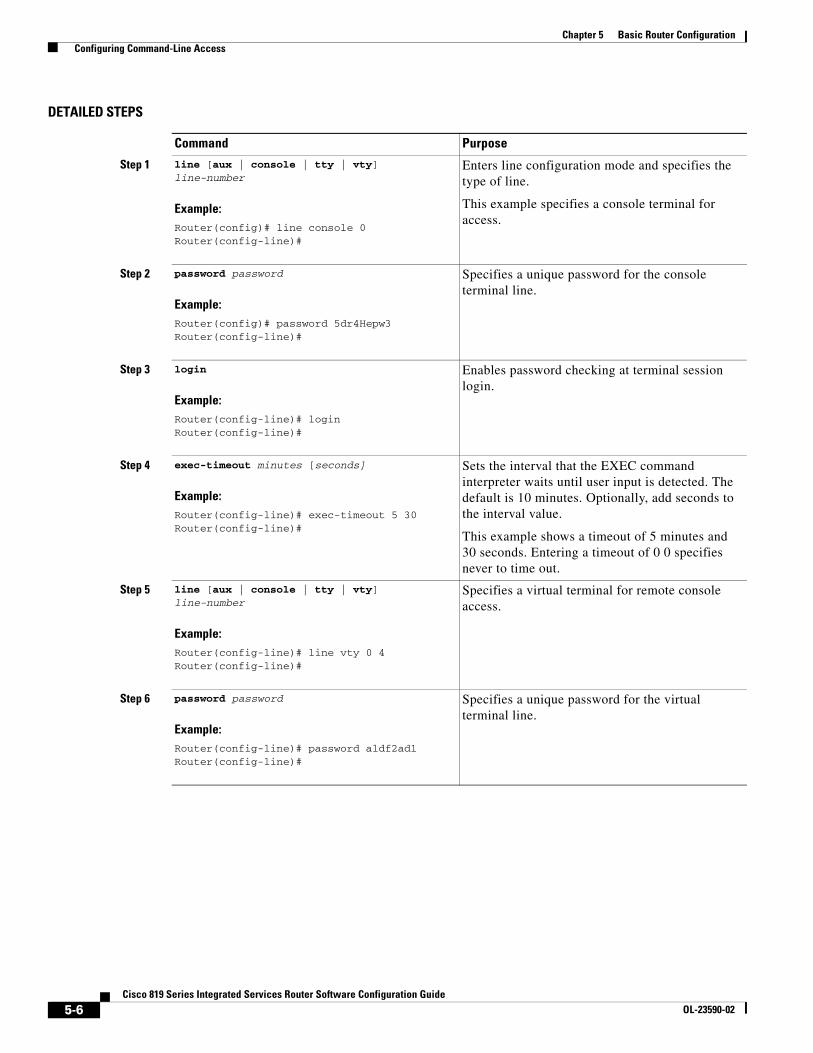
DETAILED STEPS
Command Purpose
Step 1 line [aux | console | tty | vty] line-number
Example:Router(config)# line console 0Router(config-line)#
Enters line configuration mode and specifies the type of line.
This example specifies a console terminal for access.
Step 2 password password
Example:Router(config)# password 5dr4Hepw3Router(config-line)#
Specifies a unique password for the console terminal line.
Step 3 login
Example:Router(config-line)# loginRouter(config-line)#
Enables password checking at terminal session login.
Step 4 exec-timeout minutes [seconds]
Example:Router(config-line)# exec-timeout 5 30Router(config-line)#
Sets the interval that the EXEC command interpreter waits until user input is detected. The default is 10 minutes. Optionally, add seconds to the interval value.
This example shows a timeout of 5 minutes and 30 seconds. Entering a timeout of 0 0 specifies never to time out.
Step 5 line [aux | console | tty | vty] line-number
Example:Router(config-line)# line vty 0 4Router(config-line)#
Specifies a virtual terminal for remote console access.
Step 6 password password
Example:Router(config-line)# password aldf2ad1Router(config-line)#
Specifies a unique password for the virtual terminal line.
5-6Cisco 819 Series Integrated Services Router Software Configuration Guide
OL-23590-02

Chapter 5 Basic Router Configuration Configuring Command-Line Access
Example
The following configuration shows the command-line access commands.
You do not need to input the commands marked “default.” These commands appear automatically in the configuration file generated when you use the show running-config command.
!line con 0exec-timeout 10 0password 4youreyesonlylogintransport input none (default)stopbits 1 (default)line vty 0 4password secretlogin!
Step 7 login
Example:Router(config-line)# loginRouter(config-line)#
Enables password checking at the virtual terminal session login.
Step 8 end
Example:Router(config-line)# endRouter#
Exits line configuration mode, and returns to privileged EXEC mode.
Command Purpose
5-7Cisco 819 Series Integrated Services Router Software Configuration Guide
OL-23590-02

Chapter 5 Basic Router Configuration Configuring Global Parameters
Configuring Global ParametersTo configure selected global parameters for your router, perform these steps:
SUMMARY STEPS
1. configure terminal
2. hostname name
3. enable secret password
4. no ip domain-lookup
DETAILED STEPS
Configuring WAN InterfacesConfigure the WAN interface for your router using one of the following as appropriate:
• Configuring a Gigabit Ethernet WAN Interface, page 5-9
• Configuring the Cellular Wireless WAN Interface, page 5-10
Command Purpose
Step 1 configure terminal
Example:Router> enableRouter# configure terminalRouter(config)#
Enters global configuration mode, when using the console port.
If you are connecting to the router using a remote terminal, use the following:
telnet router name or addressLogin: login idPassword: *********Router> enable
Step 2 hostname name
Example:Router(config)# hostname RouterRouter(config)#
Specifies the name for the router.
Step 3 enable secret password
Example:Router(config)# enable secret cr1ny5hoRouter(config)#
Specifies an encrypted password to prevent unauthorized access to the router.
Step 4 no ip domain-lookup
Example:Router(config)# no ip domain-lookup Router(config)#
Disables the router from translating unfamiliar words (typos) into IP addresses.
5-8Cisco 819 Series Integrated Services Router Software Configuration Guide
OL-23590-02
Chapter 5 Basic Router Configuration Configuring WAN Interfaces
• Configuring Dual SIM, page 5-22
• Configuring GPS, page 5-23
• Configuring Router for Image and Config Recovery Using Push Button, page 5-27
Configuring a Gigabit Ethernet WAN InterfaceTo configure the Ethernet interface on a Cisco 819 ISR, perform these steps, beginning in global configuration mode:
SUMMARY STEPS
1. interface type number
2. ip address ip-address mask
3. no shutdown
4. exit
5-9Cisco 819 Series Integrated Services Router Software Configuration Guide
OL-23590-02

Chapter 5 Basic Router Configuration Configuring WAN Interfaces
DETAILED STEPS
Configuring the Cellular Wireless WAN InterfaceThe Cisco 819 ISRs provide a Third-Generation (3G) wireless interface for use over Global System for Mobile Communications (GSM) and code division multiple access (CDMA) networks. The interface is a 34-millimetre embedded mini express card.
Its primary application is WAN connectivity as a backup data link for critical data applications. However, the 3G wireless interface can also function as the router’s primary WAN connection.
To configure the 3G cellular wireless interface, follow these guidelines and procedures:
• Prerequisites for Configuring the 3G Wireless Interface, page 5-11
• Restrictions for Configuring the Cellular Wireless Interface, page 5-11
• Data Account Provisioning, page 5-12
• Configuring a Cellular Interface, page 5-15
• Configuring DDR, page 5-17
• Examples for Configuring Cellular Wireless Interfaces, page 5-20
• Configuring Dual SIM, page 5-22
• Configuring GPS, page 5-23
Command Purpose
Step 1 interface type number
Example:Router(config)# interface gigabitethernet 0Router(config-if)#
Enters the configuration mode for a Gigabit Ethernet WAN interface on the router.
Step 2 ip address ip-address mask
Example:Router(config-if)# ip address 192.168.12.2 255.255.255.0Router(config-if)#
Sets the IP address and subnet mask for the specified Gigabit Ethernet interface.
Step 3 no shutdown
Example:Router(config-if)# no shutdownRouter(config-if)#
Enables the Ethernet interface, changing its state from administratively down to administratively up.
Step 4 exit
Example:Router(config-if)# exitRouter(config)#
Exits configuration mode for the Gigabit Ethernet interface and returns to global configuration mode.
5-10Cisco 819 Series Integrated Services Router Software Configuration Guide
OL-23590-02
Chapter 5 Basic Router Configuration Configuring WAN Interfaces
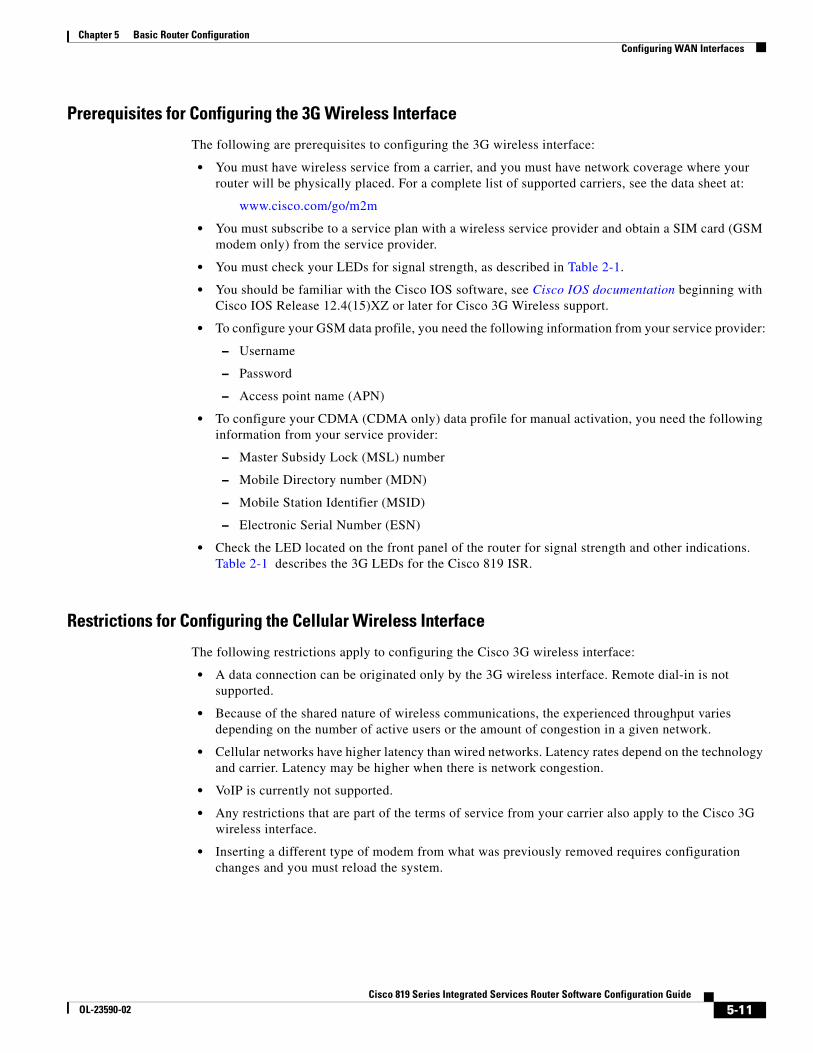
Prerequisites for Configuring the 3G Wireless Interface
The following are prerequisites to configuring the 3G wireless interface:
• You must have wireless service from a carrier, and you must have network coverage where your router will be physically placed. For a complete list of supported carriers, see the data sheet at:
www.cisco.com/go/m2m
• You must subscribe to a service plan with a wireless service provider and obtain a SIM card (GSM modem only) from the service provider.
• You must check your LEDs for signal strength, as described in Table 2-1.
• You should be familiar with the Cisco IOS software, see Cisco IOS documentation beginning with Cisco IOS Release 12.4(15)XZ or later for Cisco 3G Wireless support.
• To configure your GSM data profile, you need the following information from your service provider:
– Username
– Password
– Access point name (APN)
• To configure your CDMA (CDMA only) data profile for manual activation, you need the following information from your service provider:
– Master Subsidy Lock (MSL) number
– Mobile Directory number (MDN)
– Mobile Station Identifier (MSID)
– Electronic Serial Number (ESN)
• Check the LED located on the front panel of the router for signal strength and other indications. Table 2-1 describes the 3G LEDs for the Cisco 819 ISR.
Restrictions for Configuring the Cellular Wireless Interface
The following restrictions apply to configuring the Cisco 3G wireless interface:
• A data connection can be originated only by the 3G wireless interface. Remote dial-in is not supported.
• Because of the shared nature of wireless communications, the experienced throughput varies depending on the number of active users or the amount of congestion in a given network.
• Cellular networks have higher latency than wired networks. Latency rates depend on the technology and carrier. Latency may be higher when there is network congestion.
• VoIP is currently not supported.
• Any restrictions that are part of the terms of service from your carrier also apply to the Cisco 3G wireless interface.
• Inserting a different type of modem from what was previously removed requires configuration changes and you must reload the system.
5-11Cisco 819 Series Integrated Services Router Software Configuration Guide
OL-23590-02

Chapter 5 Basic Router Configuration Configuring WAN Interfaces
Data Account Provisioning
Note To provision your modem, you must have an active wireless account with a service provider. A SIM card must be installed in a GSM 3G wireless card.
To provision your data account, follow these procedures:
• Verifying Signal Strength and Service Availability, page 5-12
• Configuring a GSM Modem Data Profile, page 5-13
• CDMA Modem Activation and Provisioning, page 5-14
Verifying Signal Strength and Service Availability
To verify the signal strength and service availability on your modem, use the following commands in privileged EXEC mode.
SUMMARY STEPS
1. show cellular 0 network
2. show cellular 0 hardware
3. show cellular 0 connection
4. show cellular 0 gps
5. show cellular 0 radio
6. show cellular 0 profile
7. show cellular 0 security
8. show cellular 0 sms
9. show cellular 0 all
DETAILED STEPS
Command or Action Purpose
Step 1 show cellular 0 network
Example:Router# show cellular 0 network
Displays information about the carrier network, cell site, and available service.
Step 2 show cellular 0 hardware
Example:Router# show cellular 0 hardware
Displays the cellular modem hardware information.
Step 3 show cellular 0 connection
Example:Router# show cellular 0 connection
Displays the current active connection state and data statistics.
5-12Cisco 819 Series Integrated Services Router Software Configuration Guide
OL-23590-02

Chapter 5 Basic Router Configuration Configuring WAN Interfaces
Configuring a GSM Modem Data Profile
To configure or create a new modem data profile, enter the following command in privileged EXEC mode.
SUMMARY STEPS
1. cellular 0 gsm profile create <profile number> <apn> <authentication> <username> <password> ipv4
DETAILED STEPS
Table 5-2 lists the modem data profile parameters.
Step 4 show cellular 0 gps
Example:Router# show cellular 0 gps
Displays the cellular gps information.
Step 5 show cellular 0 radio
Example:Router# show cellular 0 radio
Shows the radio signal strength.
Note The RSSI should be better than –90 dBm for steady and reliable connection.
Step 6 show cellular 0 profile
Example:Router# show cellular 0 profile
Shows information about the modem data profiles created.
Step 7 show cellular 0 security
Example:Router# show cellular 0 security
Shows the security information for the modem, such as SIM and modem lock status.
Step 8 show cellular 0 sms
Example:Router# show cellular 0 sms
Displays the cellular sms information.
Step 9 show cellular 0 all
Example:Router# show cellular 0 all
Shows consolidated information about the modem, such as the profiles that were created, the radio signal strength, the network security, and so on.
Command or Action Purpose
Command or Action Purpose
Step 1 cellular 0 gsm profile create <profile number> <apn> <authentication> <username> <password> ipv4
Example:Router# gsm profile create 2 <apn-name> chap username password ipv4
Creates a new modem data profile. See Table 5-2 for details about the command parameters.
5-13Cisco 819 Series Integrated Services Router Software Configuration Guide
OL-23590-02

Chapter 5 Basic Router Configuration Configuring WAN Interfaces
CDMA Modem Activation and Provisioning
Activation procedures may differ, depending upon your carrier. Consult your carrier, and perform one of the following procedures as appropriate:
• Manual activation
• Activating using over-the-air service provisioning
The following table lists the activation and provisioning processes supported by different wireless carriers.
Manual Activation
Note You must have valid mobile directory number (MDN), mobile subsidy lock (MSL), and mobile station identifier (MSID) information from your carrier before you start this procedure.
To configure a modem profile manually, use the following command, beginning in EXEC mode:
cellular unit cdma activate manual mdn msid msl
Besides being activated, the modem data profile is provisioned through the Internet Over the Air (IOTA) process. The IOTA process is initiated automatically when you use the cellular unit cdma activate manual mdn msid msl command.
The following is a sample output from this command:
router# cellular 0 cdma activate manual 1234567890 1234567890 12345 NAM 0 will be configured and will become ActiveModem will be activated with following Parameters MDN :1234567890; MSID :1234567890; SID :1234; NID 12:Checking Current Activation StatusModem activation status: Not ActivatedBegin ActivationAccount activation - Step 1 of 5Account activation - Step 2 of 5Account activation - Step 3 of 5
Table 5-2 Modem Data Profile Parameters
profile number Number for the profile that you are creating. You can create up to 16 profiles.
apn Access point name. You must get this information from the service provider.
authentication Type of authentication, for example, CHAP, PAP.
Username Username provided by your service provider.
Password Password provided by your service provider.
Activation and Provisioning Process Carrier
Manual Activation using MDN, MSID, MSL Sprint
OTASP1 Activation
1. OTASP=Over the Air Service Provisioning.
Verizon Wireless
IOTA2 for Data Profile refresh
2. IOTA=Internet Over the Air.
Sprint
5-14Cisco 819 Series Integrated Services Router Software Configuration Guide
OL-23590-02

Chapter 5 Basic Router Configuration Configuring WAN Interfaces
Account activation - Step 4 of 5Account activation - Step 5 of 5Secure Commit Result: SucceedDone Configuring - Resetting the modemThe activation of the account is CompleteWaiting for modem to be ready to start IOTABeginning IOTArouter#*Feb 6 23:29:08.459: IOTA Status Message Received. Event: IOTA Start, Result: SUCCESS*Feb 6 23:29:08.459: Please wait till IOTA END message is received*Feb 6 23:29:08.459: It can take up to 5 minutes*Feb 6 23:29:27.951: OTA State = SPL unlock, Result = Success*Feb 6 23:29:32.319: OTA State = Parameters committed to NVRAM, Result = Success*Feb 6 23:29:40.999: Over the air provisioning complete; Result:Success*Feb 6 23:29:41.679: IOTA Status Message Received. Event: IOTA End, Result: SUCCESS
The IOTA start and end must have “success” as the resulting output. If you receive an error message, you can run IOTA independently by using the cellular cdma activate iota command.
Your carrier may require periodic refreshes of the data profile. Use the following command to refresh the data profile:
cellular cdma activate iota
Activating with Over-the-Air Service Provisioning
To provision and activate your modem using Over-the-Air Service Provisioning (OTASP), use the following command, beginning in EXEC mode.
router # cellular 0 cdma activate otasp phone_number
Note You need to obtain the phone number for use with this command from your carrier. The standard OTASP calling number is *22899.
The following is a sample output from this command:
router# cellular 0 cdma activate otasp *22899Beginning OTASP activationOTASP number is *22899819H#OTA State = SPL unlock, Result = Successrouter#OTA State = PRL downloaded, Result = SuccessOTA State = Profile downloaded, Result = SuccessOTA State = MDN downloaded, Result = SuccessOTA State = Parameters committed to NVRAM, Result = SuccessOver the air provisioning complete; Result:Success
Configuring a Cellular Interface
To configure the cellular interface, enter the following commands, beginning in privileged EXEC mode.
SUMMARY STEPS
1. configure terminal
2. interface cellular 0
3. encapsulation ppp
5-15Cisco 819 Series Integrated Services Router Software Configuration Guide
OL-23590-02

Chapter 5 Basic Router Configuration Configuring WAN Interfaces
4. ppp chap hostname hostname
5. ppp chap password 0 password
6. asynchronous mode interactive
7. ip address negotiated
Note The PPP Challenge Handshake Authentication Protocol (CHAP) authentication parameters that you use in this procedure must be the same as the username and password provided by your carrier and configured only under the GSM profile. CDMA does not require a username or password.
DETAILED STEPS
Command or Action Purpose
Step 1 configure terminal
Example:Router# configure terminal
Enters global configuration mode from the terminal.
Step 2 interface cellular 0
Example:Router (config)# interface cellular 0
Specifies the cellular interface.
Step 3 encapsulation ppp
Example:Router (config-if)# encapsulation ppp
Specifies PPP encapsulation for an interface configured for dedicated asynchronous mode or dial-on-demand routing (DDR).
Step 4 ppp chap hostname hostname
Example:Router (config-if)# ppp chap hostname [email protected]
Defines an interface-specific Challenge Handshake Authentication Protocol (CHAP) hostname. This must match the username given by the carrier. Applies to GSM only.
Step 5 ppp chap password 0 password
Example:Router (config-if)# ppp chap password 0 cisco
Defines an interface-specific CHAP password. This must match the password given by the carrier.
Step 6 asynchronous mode interactive
Example:Router (config-if)# asynchronous mode interactive
Returns a line from dedicated asynchronous network mode to interactive mode, enabling the slip and ppp commands in privileged EXEC mode.
Step 7 ip address negotiated
Example:Router (config-if)# ip address negotiated
Specifies that the IP address for a particular interface is obtained via PPP and IPCP address negotiation.
5-16Cisco 819 Series Integrated Services Router Software Configuration Guide
OL-23590-02

Chapter 5 Basic Router Configuration Configuring WAN Interfaces
Note When the cellular interface requires a static IP address, the address may be configured as ip address negotiated. Through IP Control Protocol (IPCP), the network ensures that the correct static IP address is allocated to the device. If a tunnel interface is configured with the ip address unnumbered <cellular interface> command, the actual static IP address must be configured under the cellular interface, in place of ip address negotiated. For a sample cellular interface configuration, see the “Basic Cellular Interface Configuration” section on page 5-20.
Configuring DDR
Perform these steps to configure dial-on-demand routing (DDR) for the cellular interface.
SUMMARY STEPS
1. configure terminal
2. interface cellular 0
3. dialer in-band
4. dialer idle-timeout seconds
5. dialer string string
6. dialer group number
7. exit
8. dialer-list dialer-group protocol protocol-name {permit | deny | list access-list-number | access-group}
9. ip access-list <access list number> permit <ip source address>
10. line 3
11. script dialer <regexp>
12. exit
13. chat-script <script name> ”” “ATDT*99*<profile number>#” TIMEOUT <timeout value> CONNECTorchat-script <script name> "" "ATDT*777*<profile number>#" TIMEOUT <timeout value> CONNECT
14. interface cellular 0
15. dialer string <string>
5-17Cisco 819 Series Integrated Services Router Software Configuration Guide
OL-23590-02

Chapter 5 Basic Router Configuration Configuring WAN Interfaces
DETAILED STEPS
Command or Action Purpose
Step 1 configure terminal
Example:Router# configure terminal
Enters global configuration mode.
Step 2 interface cellular 0
Example:Router (config)# interface cellular 0
Specifies the cellular interface.
Step 3 dialer in-band
Example:Router (config-if)# dialer in-band
Enables DDR and configures the specified serial interface for in-band dialing.
Step 4 dialer idle-timeout seconds
Example:Router (config-if)# dialer idle-timeout 30
Specifies the duration of idle time, in seconds, after which a line is disconnected.
Step 5 dialer string string
Example:Router (config-if)# dialer string gsm
Specifies the number or string to dial. Use the name of the chat script here.
Step 6 dialer-group number
Example:Router (config-if)# dialer-group 1
Specifies the number of the dialer access group to which a specific interface belongs.
Step 7 exit
Example:Router (config-if)# exit
Enters the global configuration mode.
Step 8 dialer-list dialer-group protocol protocol-name {permit | deny | list access-list-number | access-group}
Example:Router (config)# dialer-list 1 protocol ip list 1
Creates a dialer list for traffic of interest and permits access to an entire protocol.
Step 9 ip access-list <access list number> permit <ip source address>
Example:Router (config)# ip access list 1 permit any
Defines traffic of interest.
5-18Cisco 819 Series Integrated Services Router Software Configuration Guide
OL-23590-02

Chapter 5 Basic Router Configuration Configuring WAN Interfaces
Step 10 line 3
Example:Router (config-line)# line 3
Specifies the line configuration mode. It is always 3.
Step 11 script dialer <regexp>
Example:Router (config-line)# script-dialer gsm
Specifies a default modem chat script.
Step 12 exit
Example:Router (config-line)# exit
Exits line configuration mode.
Step 13 For GSM:chat-script <script name> ”” “ATDT*99*<profile number>#” TIMEOUT <timeout value> CONNECT
For CDMA:chat-script <script name> "" "ATDT*777*<profile number>#" TIMEOUT <timeout value> CONNECT
Example:Router (config)# chat-script gsm "" "ATDT*98*2#" TIMEOUT 60 "CONNECT“
Configures this line for GSM.
Configures this line for CDMA.
Defines the Attention Dial Tone (ATDT) commands when the dialer is initiated.
Step 14 interface cellular 0
Example:Router (config)# interface cellular 0
Specifies the cellular interface.
Step 15 dialer string string
Example:Router (config)# dialer string gsm
Specifies the dialer script (defined using the chat script command).
Command or Action Purpose
5-19Cisco 819 Series Integrated Services Router Software Configuration Guide
OL-23590-02

Chapter 5 Basic Router Configuration Configuring WAN Interfaces
Examples for Configuring Cellular Wireless Interfaces
This section provides the following configuration examples:
• Basic Cellular Interface Configuration, page 5-20
• Tunnel over Cellular Interface Configuration, page 5-21
• Configuration for 8705 modem, page 5-21
Basic Cellular Interface Configuration
The following example shows how to configure a gsm cellular interface to be used as a primary WAN connection. It is configured as the default route.
chat-script gsm "" "ATDT*98*2#" TIMEOUT 60 "CONNECT“
!interface Cellular0 ip address negotiated encapsulation ppp dialer in-band dialer string gsm dialer-group 1 async mode interactive ppp chap hostname [email protected] ppp chap password 0 cisco ppp ipcp dns request!
ip route 0.0.0.0 0.0.0.0 Cellular0!!access-list 1 permit anydialer-list 1 protocol ip list 1!line 3 exec-timeout 0 0 script dialer gsm login modem InOut
The following example shows how to configure a cdma cellular interface to be used as a primary WAN connection. It is configured as the default route.
chat-script cdma "" "ATDT#777" TIMEOUT 60 "CONNECT“
!interface Cellular0 ip address negotiated encapsulation ppp dialer in-band dialer string cdma dialer-group 1 async mode interactive ppp chap password 0 cisco!
ip route 0.0.0.0 0.0.0.0 Cellular0!!access-list 1 permit anydialer-list 1 protocol ip list 1!
5-20Cisco 819 Series Integrated Services Router Software Configuration Guide
OL-23590-02
Chapter 5 Basic Router Configuration Configuring WAN Interfaces
line 3 exec-timeout 0 0 script dialer cdma login modem InOut
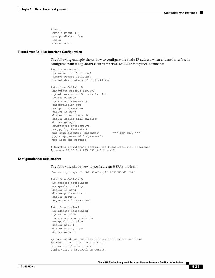
Tunnel over Cellular Interface Configuration
The following example shows how to configure the static IP address when a tunnel interface is configured with the ip address unnumbered <cellular interface> command:
interface Tunnel2 ip unnumbered Cellular0 tunnel source Cellular0 tunnel destination 128.107.248.254
interface Cellular0 bandwidth receive 1400000 ip address 23.23.0.1 255.255.0.0 ip nat outside ip virtual-reassembly encapsulation ppp no ip mroute-cache dialer in-band dialer idle-timeout 0 dialer string dial<carrier> dialer-group 1 async mode interactive no ppp lcp fast-start ppp chap hostname <hostname> *** gsm only *** ppp chap password 0 <password> ppp ipcp dns request ! traffic of interest through the tunnel/cellular interfaceip route 10.10.0.0 255.255.0.0 Tunnel2
Configuration for 8705 modem
The following shows how to configure an HSPA+ modem:
chat-script hspa "" "AT!SCACT=1,1" TIMEOUT 60 "OK"
interface Cellular0 ip address negotiated encapsulation slip dialer in-band dialer pool-member 1 dialer-group 1 async mode interactive
interface Dialer1 ip address negotiated ip nat outside ip virtual-reassembly in encapsulation slip dialer pool 1 dialer string hspa dialer-group 1
ip nat inside source list 1 interface Dialer1 overload ip route 0.0.0.0 0.0.0.0 Dialer1 access-list 1 permit any dialer-list 1 protocol ip permit
5-21Cisco 819 Series Integrated Services Router Software Configuration Guide
OL-23590-02

Chapter 5 Basic Router Configuration Configuring WAN Interfaces
line 3 script dialer hspa+ modem InOut no exec transport input all
Configuring Dual SIMThe Dual SIM feature implements auto-switch and failover between two cellular networks on a Cisco 819 ISR. This feature is enabled by default with SIM slot 0 being the primary slot and slot 1 being the secondary (failover) slot.
You can configure the Dual SIM feature using the following commands:
Note the following:
• For auto-switch and failover to work, configure the SIM profile for slots 0 and 1 using the gsm sim profile command.
• For auto-switch and failover to work, configure the chat script without a specific profile number.
• If no SIM profile is configured, profile #1 is used by default.
• If no GSM failover timer is configured, the default failover timeout is 2 minutes.
• If no GSM SIM primary slot is configured, the default primary SIM is slot 0.
The following example shows you how to set the SIM switchover timeout period to 3 minutes:
router# conf trouter(config-controller)# gsm failovertimer 3
The following example shows you how to authenticate using an unencrypted pin:
router(config-controller)# gsm sim authenticate 0 1234 slot 0
The following example shows you how to set the maximum number of SIM switchover retries to 20:
router(config-controller)# gsm sim max-retry 20
The following example shows you how to set SIM slot 1 as the primary slot:
router(config-controller)# gsm sim primary slot 1
The following example shows you how to configure the SIM card in slot 0 to use profile 10:
router(config-controller)# gsm sim profile 10 slot 0
Command Syntax Description
gsm failovertimer gsm failovertimer <1-7> Sets the failover timer in minutes.
gsm sim authenticate gsm sim authenticate <0,7> <pin> slot <0-1> Verifies the SIM CHV1 code.
gsm sim max-retry gsm sim max-retry <0-65535> Specifies the maximum number of failover retries. The default value is 10.
gsm sim primary slot gsm sim primary slot <0-1> Modifies the primary slot assignment.
gsm sim profile gsm sim profile <1-16> slot <0-1> Configures the SIM profile.
5-22Cisco 819 Series Integrated Services Router Software Configuration Guide
OL-23590-02

Chapter 5 Basic Router Configuration Configuring WAN Interfaces
Perform the following commands to manually switch the SIM:
The following command forces the modem to connect to SIM1:
Router# cellular 0 gsm sim activate slot 1
Configuring GPSYou can configure the GPS feature using the following commands:
The following examples show how to display summary and detailed GPS data for the Cisco 819 ISR. The output contains the following information:
• GPS state and mode information
• GPS tracking state
• NMEA stream state
• GPS location and timestamp information
• GPS satellite information
router# show cellular 0 gps GPS Info-------------GPS State: GPS enabledGPS Mode Configured: standaloneLatitude: 37 Deg 24 Min 59 Sec NorthLongitude: 121 Deg 55 Min 8 Sec WestTimestamp (GMT): Thu Jul 29 11:08:39 2010Fix type: 3D, Height: -6 mHeading: 408, Velocity Horiz: 3, Velocity Vert: 0Satellite Info----------------
Command Syntax Description
cellular GSM SIM cellular GSM SIM {lock | unlock} Locks or unlocks the SIM.
gsm sim cellular <unit> gsm sim [lock | unlock] <pin> Locks or unlocks the gsm SIM.
gsm sim unblock cellular <unit> gsm sim unblock <puk> <newpin> Unblocks the gsm SIM.
gsm sim change-pin cellular <unit> gsm sim change-pin <oldpin> <newpin>
Changes the PIN of the SIM.
gsm sim activate slot cellular <unit> gsm sim activate slot <slot_no> Activates the GSM SIM.
Command Syntax Description
gsm gps mode gsm gps mode standalone Enables the GPS standalone mode.
gsm gps nmea gsm gps nmea [ip | serial] Enables the NMEA mode.
• ip—NMEA over IP interface.
• serial—NMEA over serial interface.
show cellular gps show cellular unit gps Displays a summary of GPS data.
show cellular unit gps detail Displays a detailed list of GPS data.
5-23Cisco 819 Series Integrated Services Router Software Configuration Guide
OL-23590-02

Chapter 5 Basic Router Configuration Configuring WAN Interfaces
Satellite #13, elevation 75, azimuth 46, SNR 21 ...
router# show cellular 0 gps detailGPS Info-------------GPS State: GPS enabledGPS Mode Configured: standaloneLatitude: 37 Deg 24 Min 59 Sec NorthLongitude: 121 Deg 55 Min 7 Sec WestTimestamp (GMT): Thu Jul 29 22:17:57 2010Fix type: 3D, Height: 12 mHeading: 0, Velocity Horiz: 0, Velocity Vert: 0HEPE: 2680 cmUncertainty Info: Angle: 0 deg, A: 24 m, Position: 12 m, Vertical: 12 mSatellite Info----------------Satellite #7, elevation 16, azimuth 123, SNR 14 *...
Configuring GPS NMEA
The GPS NMEA streaming to external NMEA 2.0 compliant GPS plotter applications is supported on the Cisco 819 ISRs.
To enable the NMEA data streaming, perform the following commands:
SUMMARY STEPS
1. conf t
2. controller cellular 0
3. gsm gps mode standalone
4. gsm gps nmea [ip | serial]
5. end
6. show running
7. show line
8. telnet ip address port
5-24Cisco 819 Series Integrated Services Router Software Configuration Guide
OL-23590-02

Chapter 5 Basic Router Configuration Configuring WAN Interfaces
DETAILED STEPS
Command Description
Step 1 conf t
Example:Router# conf t
Enters configuration mode.
Step 2 controller cellular 0
Example:router(config)# controller cellular 0
Enters controller cellular configuration mode.
Step 3 gsm gps mode standalone
Example:Router(config-controller)# gsm gps mode standalone
Enables standalone GPS.
Step 4 gsm gps nmea [ip | serial]
Example: Router(config-controller)# gsm gps nmea ip
Enables NMEA over IP interface.
• ip—NMEA over IP interface.
• serial—NMEA over serial interface.
Step 5 end
Example:Router(config-controller)# end
Exits controller configuration mode and returns to privileged EXEC mode.
Step 6 show running
Example:Router# show running<snip>controller Cellular 0gsm gps mode standalonegsm gps nmea ip
Shows the output of the configuration.
5-25Cisco 819 Series Integrated Services Router Software Configuration Guide
OL-23590-02
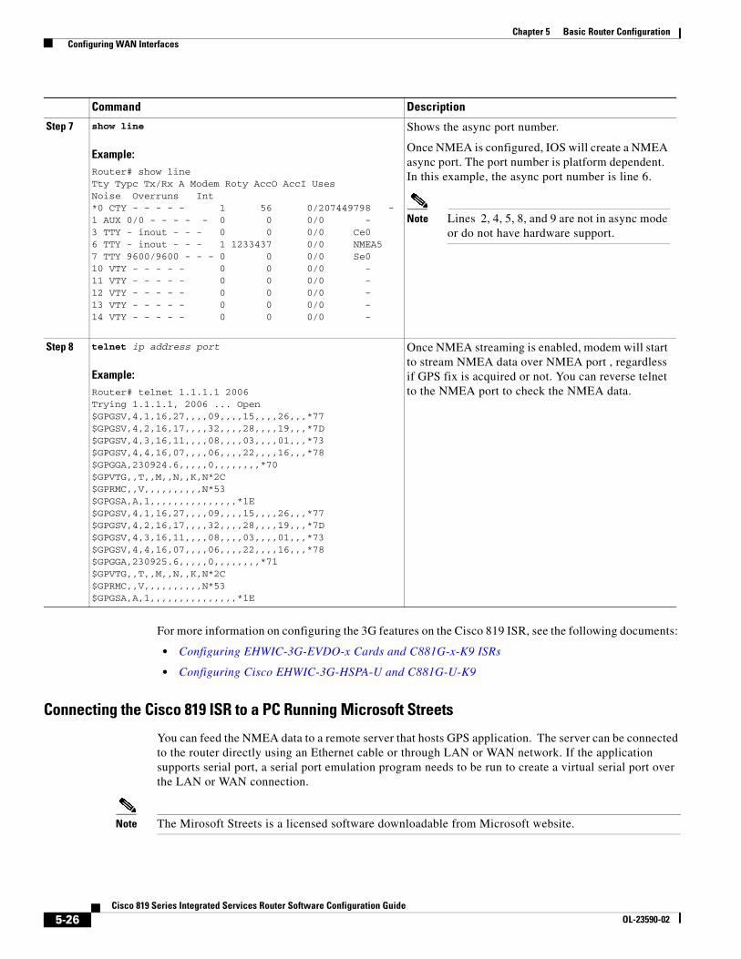
Chapter 5 Basic Router Configuration Configuring WAN Interfaces
For more information on configuring the 3G features on the Cisco 819 ISR, see the following documents:
• Configuring EHWIC-3G-EVDO-x Cards and C881G-x-K9 ISRs
• Configuring Cisco EHWIC-3G-HSPA-U and C881G-U-K9
Connecting the Cisco 819 ISR to a PC Running Microsoft Streets
You can feed the NMEA data to a remote server that hosts GPS application. The server can be connected to the router directly using an Ethernet cable or through LAN or WAN network. If the application supports serial port, a serial port emulation program needs to be run to create a virtual serial port over the LAN or WAN connection.
Note The Mirosoft Streets is a licensed software downloadable from Microsoft website.
Step 7 show line
Example:Router# show lineTty Typc Tx/Rx A Modem Roty AccO AccI Uses Noise Overruns Int*0 CTY - - - - - 1 56 0/207449798 -1 AUX 0/0 - - - - - 0 0 0/0 - 3 TTY - inout - - - 0 0 0/0 Ce06 TTY - inout - - - 1 1233437 0/0 NMEA57 TTY 9600/9600 - - - 0 0 0/0 Se010 VTY - - - - - 0 0 0/0 -11 VTY - - - - - 0 0 0/0 -12 VTY - - - - - 0 0 0/0 -13 VTY - - - - - 0 0 0/0 -14 VTY - - - - - 0 0 0/0 -
Shows the async port number.
Once NMEA is configured, IOS will create a NMEA async port. The port number is platform dependent. In this example, the async port number is line 6.
Note Lines 2, 4, 5, 8, and 9 are not in async mode or do not have hardware support.
Step 8 telnet ip address port
Example:Router# telnet 1.1.1.1 2006 Trying 1.1.1.1, 2006 ... Open$GPGSV,4,1,16,27,,,,09,,,,15,,,,26,,,*77$GPGSV,4,2,16,17,,,,32,,,,28,,,,19,,,*7D$GPGSV,4,3,16,11,,,,08,,,,03,,,,01,,,*73$GPGSV,4,4,16,07,,,,06,,,,22,,,,16,,,*78$GPGGA,230924.6,,,,,0,,,,,,,,*70$GPVTG,,T,,M,,N,,K,N*2C$GPRMC,,V,,,,,,,,,,N*53$GPGSA,A,1,,,,,,,,,,,,,,,*1E$GPGSV,4,1,16,27,,,,09,,,,15,,,,26,,,*77$GPGSV,4,2,16,17,,,,32,,,,28,,,,19,,,*7D$GPGSV,4,3,16,11,,,,08,,,,03,,,,01,,,*73$GPGSV,4,4,16,07,,,,06,,,,22,,,,16,,,*78$GPGGA,230925.6,,,,,0,,,,,,,,*71$GPVTG,,T,,M,,N,,K,N*2C$GPRMC,,V,,,,,,,,,,N*53$GPGSA,A,1,,,,,,,,,,,,,,,*1E
Once NMEA streaming is enabled, modem will start to stream NMEA data over NMEA port , regardless if GPS fix is acquired or not. You can reverse telnet to the NMEA port to check the NMEA data.
Command Description
5-26Cisco 819 Series Integrated Services Router Software Configuration Guide
OL-23590-02

Chapter 5 Basic Router Configuration Configuring WAN Interfaces
To connect the Cisco 819 ISR to a PC running Microsoft Streets, perform the following steps:
Step 1 Connect the PC to the router using an Ethernet cable.
Step 2 Ensure that the PC and router can ping.
Step 3 Launch the serial port redirector on the PC.
Step 4 Create a virtual serial port that connects to the NMEA port on the router.
Step 5 Launch the Microsoft Streets on your PC.
Step 6 Select the GPS Menu.
Step 7 Click Start Tracking.
Step 8 If a location fix is acquired from the show cellular gps command output on the router, you will see the current location plotted on the graph and a red brown dotted cursor with a circle around it on the map.
Note If no location fix is acquired, the Microsoft application times out and disconnects.
Note Obtaining a GPS-fixed location requires a supported GPS antenna to be connected to the DIV/GPS port. Obtaining a GPS-fixed location using the Standalone mode can take up to 12 minutes. This depends on the location and type of antenna used.
Configuring Router for Image and Config Recovery Using Push ButtonA push button feature is available on the Cisco 819 ISR. The reset button on the front panel of the router enables this feature.
Perform the following steps to use this feature:
Step 1 Unplug power.
Step 2 Press the reset button on the front panel of the router.
Step 3 Power up the sytem while holding down the reset button.
The system LED blinks four times indicating that the router has accepted the button push.
Using this button takes effect only during ROMMON initialization. During a warm reboot, pressing this button has no impact on performance. Table 5-3 shows the high level functionality when the button is pushed during ROMMON initialization.
5-27Cisco 819 Series Integrated Services Router Software Configuration Guide
OL-23590-02

Chapter 5 Basic Router Configuration Configuring WAN Interfaces
Use the show platform command to display the current bootup mode for the router. The following sections show sample outputs when the button is not pushed and when the button is pushed.
Output When Button Is Not Pushed: Example
router# show platform boot-record
Platform Config Boot Record :============================Configuration Register at boot time : 0x0Reset Button Status at Boot Time : Not PressedStartup-config Backup Status at Boot: No StatusStartup-config(backup file)location : No BackupGolden config file at location : No Recovery DetectedConfig Recovery Status : No Status
Output When Button Is Pushed: Example
router# show platform boot-record Platform Config Boot Record :============================Configuration Register at boot time : 0x0Reset Button Status at Boot Time : PressedStartup-config Backup Status at Boot: OkStartup-config(backup file)location : flash:/startup.backup.19000716-225840-UTCGolden config file at location : flash:/golden.cfgConfig Recovery Status : Ok
Table 5-3 Push Button Functionailty during ROMMON Initialization
ROMMON Behavior IOS Behavior
• Boots using default baud rate.
• Performs auto-boot.
• Loads the *.default image if available on compact flash
Note If no *.default image is available, the ROMMON will boot up with the first Cisco IOS image on flash.
Examples of names for default images: c800-universalk9-mz.SPA.default, c-800-universalk9_npe-mz.151T.default, image.default
Note You can only have one configuration file with *.cfg option. Having more than one file will result in uncertain operational behavior.
If the configuration named *.cfg is available in nvram storage or flash storage, IOS will perform a backup of the original configuration and will boot up using this configuration.
Note You can only have one configuration file with *.cfg option. Having more than one file will result in uncertain operational behavior.
5-28Cisco 819 Series Integrated Services Router Software Configuration Guide
OL-23590-02

Chapter 5 Basic Router Configuration Configuring a Loopback Interface
Push Button in WLAN AP
When the push button on the front panel is pressed, WLAN AP will perform both image and configuration recovery.
To perform image recovery, WLAN will go into the boot loader so that the user can download the image from the bootloader prompt.
To perform configuration recovery, WLAN AP will overwrite the contents of flash:/config.txt with the contents of flash:/cpconfig-ap802.cfg file if available in flash drive. Otherwise, flash:/config.txt will be deleted.
Configuring the Fast Ethernet LAN InterfacesThe Fast Ethernet LAN interfaces on your router are automatically configured as part of the default VLAN and are not configured with individual addresses. Access is provided through the VLAN. You may assign the interfaces to other VLANs if you want. For more information about creating VLANs, see the “Configuring the Ethernet Switches” section on page 10-1.
Configuring a Loopback InterfaceThe loopback interface acts as a placeholder for the static IP address and provides default routing information.
Perform these steps to configure a loopback interface, beginning in global configuration mode:
SUMMARY STEPS
1. interface type number
2. ip address ip-address mask
3. exit
5-29Cisco 819 Series Integrated Services Router Software Configuration Guide
OL-23590-02

Chapter 5 Basic Router Configuration Configuring a Loopback Interface
DETAILED STEPS
Example
The loopback interface in this sample configuration is used to support Network Address Translation (NAT) on the virtual-template interface. This configuration example shows the loopback interface configured on the Fast Ethernet interface with an IP address of 200.200.100.1/24, which acts as a static IP address. The loopback interface points back to virtual-template1, which has a negotiated IP address.
!interface loopback 0ip address 200.200.100.1 255.255.255.0 (static IP address)ip nat outside!interface Virtual-Template1ip unnumbered loopback0no ip directed-broadcastip nat outside!
Verifying Configuration
To verify that you have properly configured the loopback interface, enter the show interface loopback command. You should see a verification output similar to the following example:
Router# show interface loopback 0Loopback0 is up, line protocol is up Hardware is Loopback Internet address is 200.200.100.1/24 MTU 1514 bytes, BW 8000000 Kbit, DLY 5000 usec, reliability 255/255, txload 1/255, rxload 1/255 Encapsulation LOOPBACK, loopback not set Last input never, output never, output hang never Last clearing of "show interface" counters never Queueing strategy: fifo
Command Purpose
Step 1 interface type number
Example:Router(config)# interface Loopback 0Router(config-if)#
Enters configuration mode for the loopback interface.
Step 2 ip address ip-address mask
Example:Router(config-if)# ip address 10.108.1.1 255.255.255.0Router(config-if)#
Sets the IP address and subnet mask for the loopback interface.
Step 3 exit
Example:Router(config-if)# exitRouter(config)#
Exits configuration mode for the loopback interface and returns to global configuration mode.
5-30Cisco 819 Series Integrated Services Router Software Configuration Guide
OL-23590-02

Chapter 5 Basic Router Configuration Configuring Static Routes
Output queue 0/0, 0 drops; input queue 0/75, 0 drops 5 minute input rate 0 bits/sec, 0 packets/sec 5 minute output rate 0 bits/sec, 0 packets/sec 0 packets input, 0 bytes, 0 no buffer Received 0 broadcasts, 0 runts, 0 giants, 0 throttles 0 input errors, 0 CRC, 0 frame, 0 overrun, 0 ignored, 0 abort 0 packets output, 0 bytes, 0 underruns 0 output errors, 0 collisions, 0 interface resets 0 output buffer failures, 0 output buffers swapped out
Another way to verify the loopback interface is to ping it:
Router# ping 200.200.100.1 Type escape sequence to abort.Sending 5, 100-byte ICMP Echos to 200.200.100.1, timeout is 2 seconds:!!!!!Success rate is 100 percent (5/5), round-trip min/avg/max = 1/2/4 ms
Configuring Static RoutesStatic routes provide fixed routing paths through the network. They are manually configured on the router. If the network topology changes, the static route must be updated with a new route. Static routes are private routes unless they are redistributed by a routing protocol.
Follow these steps to configure static routes, beginning in global configuration mode.
SUMMARY STEPS
1. ip route prefix mask {ip-address | interface-type interface-number [ip-address]}
2. end
DETAILED STEPS
For general information on static routing, see the “Floating Static Routes” section on page B-5.
Command Purpose
Step 1 ip route prefix mask {ip-address | interface-type interface-number [ip-address]}
Example:Router(config)# ip route 192.168.1.0 255.255.0.0 10.10.10.2Router(config)#
Specifies the static route for the IP packets.
For details about this command and about additional parameters that can be set, see Cisco IOS IP Routing: Protocol-Independent Command Reference.
Step 2 end
Example:Router(config)# endRouter#
Exits router configuration mode, and enters privileged EXEC mode.
5-31Cisco 819 Series Integrated Services Router Software Configuration Guide
OL-23590-02

Chapter 5 Basic Router Configuration Configuring Dynamic Routes
ExampleIn the following configuration example, the static route sends out all IP packets with a destination IP address of 192.168.1.0 and a subnet mask of 255.255.255.0 on the Fast Ethernet interface to another device with an IP address of 10.10.10.2. Specifically, the packets are sent to the configured PVC.
You do not need to enter the command marked “(default).” This command appears automatically in the configuration file generated when you use the show running-config command.
!ip classless (default)ip route 192.168.1.0 255.255.255.0 10.10.10.2!
Verifying ConfigurationTo verify that you have properly configured static routing, enter the show ip route command and look for static routes signified by the “S.”
You should see a verification output similar to the following:
Router# show ip routeCodes: C - connected, S - static, R - RIP, M - mobile, B - BGP D - EIGRP, EX - EIGRP external, O - OSPF, IA - OSPF inter area N1 - OSPF NSSA external type 1, N2 - OSPF NSSA external type 2 E1 - OSPF external type 1, E2 - OSPF external type 2 i - IS-IS, su - IS-IS summary, L1 - IS-IS level-1, L2 - IS-IS level-2 ia - IS-IS inter area, * - candidate default, U - per-user static route o - ODR, P - periodic downloaded static route
Gateway of last resort is not set
10.0.0.0/24 is subnetted, 1 subnetsC 10.108.1.0 is directly connected, Loopback0S* 0.0.0.0/0 is directly connected, FastEthernet0
Configuring Dynamic RoutesIn dynamic routing, the network protocol adjusts the path automatically, based on network traffic or topology. Changes in dynamic routes are shared with other routers in the network.
The Cisco routers can use IP routing protocols, such as Routing Information Protocol (RIP) or Enhanced Interior Gateway Routing Protocol (EIGRP), to learn routes dynamically. You can configure either of these routing protocols on your router.
• Configuring Routing Information Protocol, page 5-33
• Configuring Enhanced Interior Gateway Routing Protocol, page 5-34
5-32Cisco 819 Series Integrated Services Router Software Configuration Guide
OL-23590-02

Chapter 5 Basic Router Configuration Configuring Dynamic Routes
Configuring Routing Information ProtocolTo configure the RIP routing protocol on the router, perform these steps, beginning in global configuration mode:
SUMMARY STEPS
1. router rip
2. version {1 | 2}
3. network ip-address
4. no auto-summary
5. end
DETAILED STEPS
For general information on RIP, see “RIP” section on page B-2.
Command Task
Step 1 router rip
Example:Router> configure terminalRouter(config)# router ripRouter(config-router)#
Enters router configuration mode, and enables RIP on the router.
Step 2 version {1 | 2}
Example:Router(config-router)# version 2Router(config-router)#
Specifies use of RIP version 1 or 2.
Step 3 network ip-address
Example:Router(config-router)# network 192.168.1.1Router(config-router)# network 10.10.7.1Router(config-router)#
Specifies a list of networks on which RIP is to be applied, using the address of the network of each directly connected network.
Step 4 no auto-summary
Example:Router(config-router)# no auto-summaryRouter(config-router)#
Disables automatic summarization of subnet routes into network-level routes. This allows subprefix routing information to pass across classfull network boundaries.
Step 5 end
Example:Router(config-router)# endRouter#
Exits router configuration mode, and enters privileged EXEC mode.
5-33Cisco 819 Series Integrated Services Router Software Configuration Guide
OL-23590-02

Chapter 5 Basic Router Configuration Configuring Dynamic Routes
Example
The following configuration example shows RIP version 2 enabled in IP network 10.0.0.0 and 192.168.1.0.
To see this configuration, use the show running-config command from privileged EXEC mode.
!Router# show running-configrouter rip version 2 network 10.0.0.0 network 192.168.1.0 no auto-summary!
Verifying Configuration
To verify that you have properly configured RIP, enter the show ip route command and look for RIP routes signified by “R.” You should see a verification output like the following example:
Router# show ip routeCodes: C - connected, S - static, R - RIP, M - mobile, B - BGP D - EIGRP, EX - EIGRP external, O - OSPF, IA - OSPF inter area N1 - OSPF NSSA external type 1, N2 - OSPF NSSA external type 2 E1 - OSPF external type 1, E2 - OSPF external type 2 i - IS-IS, su - IS-IS summary, L1 - IS-IS level-1, L2 - IS-IS level-2 ia - IS-IS inter area, * - candidate default, U - per-user static route o - ODR, P - periodic downloaded static route
Gateway of last resort is not set
10.0.0.0/24 is subnetted, 1 subnetsC 10.108.1.0 is directly connected, Loopback0R 3.0.0.0/8 [120/1] via 2.2.2.1, 00:00:02, Ethernet0/0
Configuring Enhanced Interior Gateway Routing ProtocolTo configure Enhanced Interior Gateway Routing Protocol (EIGRP), perform these steps, beginning in global configuration mode:
SUMMARY STEPS
1. router eigrp as-number
2. network ip-address
3. end
5-34Cisco 819 Series Integrated Services Router Software Configuration Guide
OL-23590-02

Chapter 5 Basic Router Configuration Configuring Dynamic Routes
DETAILED STEPS
For general information on EIGRP concept, see the “Enhanced IGRP” section on page B-3.
Example
The following configuration example shows the EIGRP routing protocol enabled in IP networks 192.145.1.0 and 10.10.12.115. The EIGRP autonomous system number is 109.
To see this configuration, use the show running-config command, beginning in privileged EXEC mode.
!router eigrp 109
network 192.145.1.0network 10.10.12.115
!
Verifying Configuration
To verify that you have properly configured IP EIGRP, enter the show ip route command and look for EIGRP routes indicated by “D.” You should see a verification output similar to the following:
Router# show ip routeCodes: C - connected, S - static, R - RIP, M - mobile, B - BGP D - EIGRP, EX - EIGRP external, O - OSPF, IA - OSPF inter area N1 - OSPF NSSA external type 1, N2 - OSPF NSSA external type 2 E1 - OSPF external type 1, E2 - OSPF external type 2 i - IS-IS, su - IS-IS summary, L1 - IS-IS level-1, L2 - IS-IS level-2 ia - IS-IS inter area, * - candidate default, U - per-user static route o - ODR, P - periodic downloaded static route
Gateway of last resort is not set 10.0.0.0/24 is subnetted, 1 subnetsC 10.108.1.0 is directly connected, Loopback0D 3.0.0.0/8 [90/409600] via 2.2.2.1, 00:00:02, Ethernet0/0
Command Purpose
Step 1 router eigrp as-number
Example:Router(config)# router eigrp 109Router(config)#
Enters router configuration mode and enables EIGRP on the router. The autonomous-system number identifies the route to other EIGRP routers and is used to tag the EIGRP information.
Step 2 network ip-address
Example:Router(config)# network 192.145.1.0Router(config)# network 10.10.12.115Router(config)#
Specifies a list of networks on which EIGRP is to be applied, using the IP address of the network of directly connected networks.
Step 3 end
Example:Router(config-router)# endRouter#
Exits router configuration mode and enters privileged EXEC mode.
5-35Cisco 819 Series Integrated Services Router Software Configuration Guide
OL-23590-02

Chapter 5 Basic Router Configuration Configuring Dynamic Routes
5-36Cisco 819 Series Integrated Services Router Software Configuration Guide
OL-23590-02
Cisco 819 Series IntegraOL-23590-02
C H A P T E R 6
Configuring Backup Data Lines and Remote ManagementThis chapter describes configuring backup data lines and remote management in the following sections:
• Configuring Backup Interfaces, page 6-1
• Configuring Cellular Dial-on-Demand Routing Backup, page 6-3
• Configuring Dial Backup and Remote Management Through the Console Port, page 6-8.
The Cisco 819 Integrated Services Router (ISR) supports backup data connectivity with a backup data line that enables them to mitigate WAN downtime.
Cisco 819 ISRs also support remote management functions through the auxiliary port on any Cisco 819 series ISRs.
Note On the Cisco 819 ISRs, the console port and the auxiliary port are on the same physical RJ-45 port. Therefore, the two ports cannot be activated simultaneously. You must use the command-line interface (CLI) to enable the desired function.
Configuring Backup InterfacesWhen the router receives an indication that the primary interface is down, the backup interface becomes enabled. After the primary connection has been restored for a specified period, the backup interface is disabled.
Even if the backup interface comes out of standby mode, the router does not enable the backup interface unless the router receives the traffic specified for that backup interface.
Table 6-1 shows the backup interfaces available for each Cisco 819 ISR, along with their port designations. Basic configurations for these interfaces are given in the “Configuring WAN Interfaces” section on page 5-8.
Table 6-1 Model Number and Data Line Backup Capabilities
Router Model Number 3G
819 Yes
6-1ted Services Routers Software Configuration Guide

Chapter 6 Configuring Backup Data Lines and Remote Management Configuring Backup Interfaces
To configure your router with a backup interface, perform these steps, beginning in global configuration mode:
SUMMARY STEPS
1. interface type number
2. backup interface interface-type interface-number
3. exit
DETAILED STEPS
Command Purpose
Step 1 interface type number
Example:Router(config)# interface xxx 0Router(config-if)#
Enters interface configuration mode for the interface for which you want to configure backup.
This can be a serial interface, ISDN interface, or asynchronous interface.
Step 2 backup interface interface-type interface-number
Example:Router(config-if)# backup interface serial 0Router(config-if)#
Assigns an interface as the secondary, or backup interface.
This can be a serial interface or asynchronous interface. For example, a serial 1 interface could be configured to back up a serial 0 interface.
The example shows a serial interface configured as the backup interface for the ATM 0 interface.
Step 3 exit
Example:Router(config-if)# exitRouter(config)#
Exits the configuration interface mode.
6-2Cisco 819 Series Integrated Services Routers Software Configuration Guide
OL-23590-02

Chapter 6 Configuring Backup Data Lines and Remote Management Configuring Cellular Dial-on-Demand Routing Backup
Configuring Cellular Dial-on-Demand Routing BackupTo monitor the primary connection and initiate the backup connection over the cellular interface when needed, the router can use one of the following methods:
• Backup Interface—The backup interface that stays in standby mode until the primary interface line protocol is detected as down and then is brought up. See the “Configuring Backup Interfaces” section on page 6-1.
• Dialer Watch—Dialer watch is a backup feature that integrates dial backup with routing capabilities. See the “Configuring DDR Backup Using Dialer Watch” section on page 6-3.
• Floating Static Route—The route through the backup interface has an administrative distance that is greater than the administrative distance of the primary connection route and therefore would not be in the routing table until the primary interface goes down. When the primary interaface goes down, the floating static route is used. See the “Configuring DDR Backup Using Floating Static Route” section on page 6-5
Note You cannot configure a backup interface for the cellular interface and any other asynchronous serial interface.
Configuring DDR Backup Using Dialer WatchTo initiate dialer watch, you must configure the interface to perform dial-on-demand routing (DDR) and backup. Use traditional DDR configuration commands, such as dialer maps, for DDR capabilities. To enable dialer watch on the backup interface and create a dialer list, use the following commands in interface configuration mode.
SUMMARY STEPS
1. configure terminal
2. interface type number
3. dialer watch group group-number
4. dialer watch-list group-number ip ip-address address-mask
5. dialer-list <dialer-group> protocol <protocol name> {permit | deny | list <access list number> | access-group}
6. ip access-list <access list number> permit <ip source address>
7. interface cellular 0
8. dialer string <string>
6-3Cisco 819 Series Integrated Services Routers Software Configuration Guide
OL-23590-02
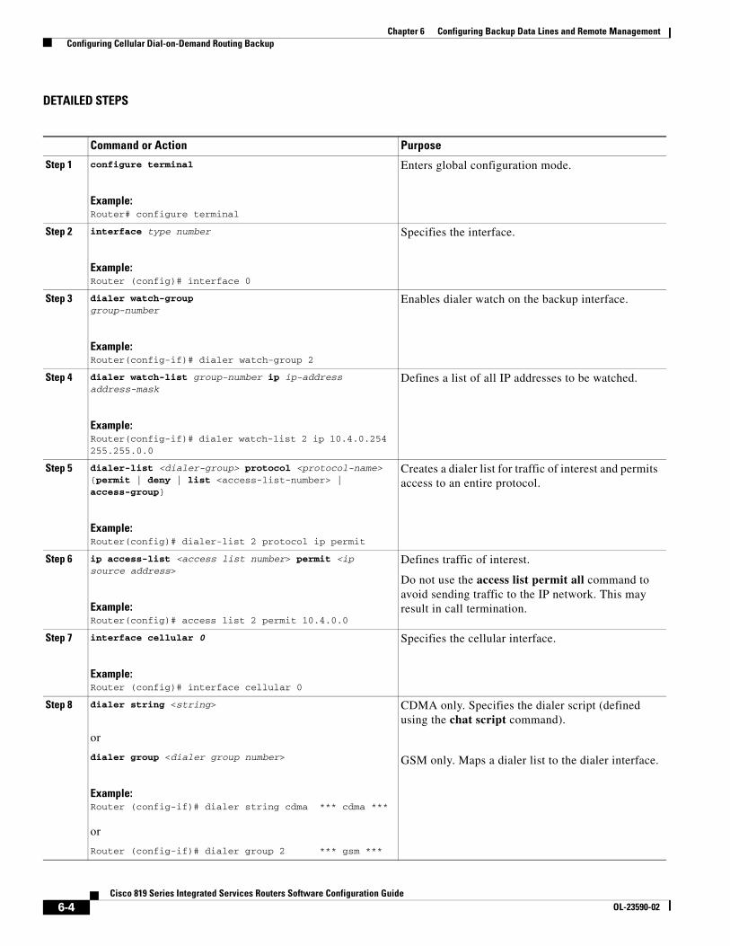
Chapter 6 Configuring Backup Data Lines and Remote Management Configuring Cellular Dial-on-Demand Routing Backup
DETAILED STEPS
Command or Action Purpose
Step 1 configure terminal
Example:Router# configure terminal
Enters global configuration mode.
Step 2 interface type number
Example:Router (config)# interface 0
Specifies the interface.
Step 3 dialer watch-groupgroup-number
Example:Router(config-if)# dialer watch-group 2
Enables dialer watch on the backup interface.
Step 4 dialer watch-list group-number ip ip-address address-mask
Example:Router(config-if)# dialer watch-list 2 ip 10.4.0.254 255.255.0.0
Defines a list of all IP addresses to be watched.
Step 5 dialer-list <dialer-group> protocol <protocol-name> {permit | deny | list <access-list-number> | access-group}
Example:Router(config)# dialer-list 2 protocol ip permit
Creates a dialer list for traffic of interest and permits access to an entire protocol.
Step 6 ip access-list <access list number> permit <ip source address>
Example:Router(config)# access list 2 permit 10.4.0.0
Defines traffic of interest.
Do not use the access list permit all command to avoid sending traffic to the IP network. This may result in call termination.
Step 7 interface cellular 0
Example:Router (config)# interface cellular 0
Specifies the cellular interface.
Step 8 dialer string <string>
or
dialer group <dialer group number>
Example:Router (config-if)# dialer string cdma *** cdma ***
or
Router (config-if)# dialer group 2 *** gsm ***
CDMA only. Specifies the dialer script (defined using the chat script command).
GSM only. Maps a dialer list to the dialer interface.
6-4Cisco 819 Series Integrated Services Routers Software Configuration Guide
OL-23590-02

Chapter 6 Configuring Backup Data Lines and Remote Management Configuring Cellular Dial-on-Demand Routing Backup
Configuring DDR Backup Using Floating Static RouteTo configure a floating static default route on the secondary interface, use the following commands, beginning in the global configuration mode.
Note Make sure you have ip classless enabled on your router.
SUMMARY STEPS
1. configure terminal
2. ip route network-number network-mask {ip address | interface} [administrative distance] [name name]
DETAILED STEPS
Cellular Wireless Modem as Backup with NAT and IPsec ConfigurationThe following example shows how to configure the 3G wireless modem as backup with NAT and IPsec on either GSM or CDMA networks.
Note The receive and transmit speeds cannot be configured. The actual throughput depends on the cellular network service.
Current configuration : 3433 bytes!version 12.4no service padservice timestamps debug datetime msecservice timestamps log datetime msecno service password-encryption!hostname Router!boot-start-markerboot-end-marker
Command or Action Purpose
Step 1 configure terminal
Example:Router# configure terminal
Enters global configuration mode from the terminal.
Step 2 ip route network-number network-mask{ip-address | interface} [administrative distance] [name name]
Example:Router (config)# ip route 0.0.0.0 Dialer 2 track 234
Establishes a floating static route with the configured administrative distance through the specified interface.
A higher administrative distance should be configured for the route through the backup interface, so that the backup interface is used only when the primary interface is down.
6-5Cisco 819 Series Integrated Services Routers Software Configuration Guide
OL-23590-02

Chapter 6 Configuring Backup Data Lines and Remote Management Configuring Cellular Dial-on-Demand Routing Backup
!!no aaa new-model!!! !crypto isakmp policy 1 encr 3des authentication pre-sharecrypto isakmp key gsm address 128.107.241.234 !!crypto ipsec transform-set gsm ah-sha-hmac esp-3des !crypto map gsm1 10 ipsec-isakmp set peer 128.107.241.234 set transform-set gsm match address 103!!!no ip dhcp use vrf connectedip dhcp excluded-address 10.4.0.254!ip dhcp pool gsmpool network 10.4.0.0 255.255.0.0 dns-server 66.209.10.201 66.102.163.231 default-router 10.4.0.254 !!ip cef!no ipv6 cefmultilink bundle-name authenticatedchat-script gsm "" "atdt*98*1#" TIMEOUT 30 "CONNECT" !!archive log config hidekeys!!interface 0 no ip address ip virtual-reassembly load-interval 30 no ilmi-keepalive!interface 0.1 point-to-point backup interface Cellular0 ip nat outside ip virtual-reassembly pvc 0/35 pppoe-client dial-pool-number 2 !!interface FastEthernet0!interface FastEthernet1!interface FastEthernet2!interface FastEthernet3
6-6Cisco 819 Series Integrated Services Routers Software Configuration Guide
OL-23590-02
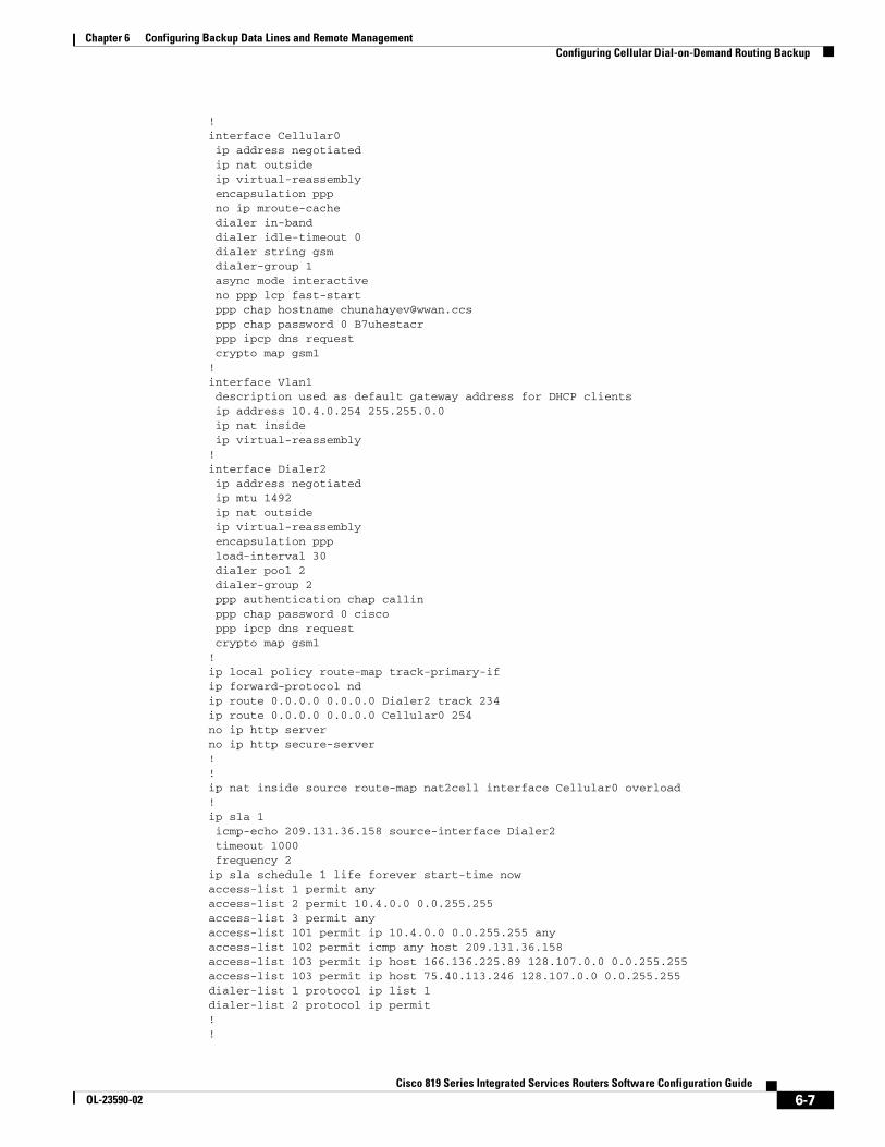
Chapter 6 Configuring Backup Data Lines and Remote Management Configuring Cellular Dial-on-Demand Routing Backup
!interface Cellular0 ip address negotiated ip nat outside ip virtual-reassembly encapsulation ppp no ip mroute-cache dialer in-band dialer idle-timeout 0 dialer string gsm dialer-group 1 async mode interactive no ppp lcp fast-start ppp chap hostname [email protected] ppp chap password 0 B7uhestacr ppp ipcp dns request crypto map gsm1 !interface Vlan1 description used as default gateway address for DHCP clients ip address 10.4.0.254 255.255.0.0 ip nat inside ip virtual-reassembly!interface Dialer2 ip address negotiated ip mtu 1492 ip nat outside ip virtual-reassembly encapsulation ppp load-interval 30 dialer pool 2 dialer-group 2 ppp authentication chap callin ppp chap password 0 cisco ppp ipcp dns request crypto map gsm1 !ip local policy route-map track-primary-ifip forward-protocol ndip route 0.0.0.0 0.0.0.0 Dialer2 track 234ip route 0.0.0.0 0.0.0.0 Cellular0 254no ip http serverno ip http secure-server!!ip nat inside source route-map nat2cell interface Cellular0 overload! ip sla 1 icmp-echo 209.131.36.158 source-interface Dialer2 timeout 1000 frequency 2ip sla schedule 1 life forever start-time nowaccess-list 1 permit anyaccess-list 2 permit 10.4.0.0 0.0.255.255access-list 3 permit anyaccess-list 101 permit ip 10.4.0.0 0.0.255.255 anyaccess-list 102 permit icmp any host 209.131.36.158access-list 103 permit ip host 166.136.225.89 128.107.0.0 0.0.255.255access-list 103 permit ip host 75.40.113.246 128.107.0.0 0.0.255.255dialer-list 1 protocol ip list 1dialer-list 2 protocol ip permit!!
6-7Cisco 819 Series Integrated Services Routers Software Configuration Guide
OL-23590-02

Chapter 6 Configuring Backup Data Lines and Remote Management Configuring Dial Backup and Remote Management Through the Console Port
!route-map track-primary-if permit 10 match ip address 102 set interface Dialer2!route-map nat2cell permit 10 match ip address 101 match interface Cellular0!!control-plane!!line con 0 no modem enableline aux 0line 3 exec-timeout 0 0 script dialer gsm login modem InOut no execline vty 0 4 login!scheduler max-task-time 5000 !webvpn cefend
Configuring Dial Backup and Remote Management Through the Console Port
When customer premises equipment, such as a Cisco 819 ISR is connected to an ISP, an IP address is dynamically assigned to the router, or the IP address may be assigned by the router peer through the centrally managed function. The dial backup feature can be added to provide a failover route in case the primary line fails. The Cisco 819 ISRs can use the auxiliary port for dial backup and remote management.
6-8Cisco 819 Series Integrated Services Routers Software Configuration Guide
OL-23590-02

Chapter 6 Configuring Backup Data Lines and Remote Management Configuring Dial Backup and Remote Management Through the Console Port
Figure 6-1 shows the network configuration used for remote management access and for providing backup to the primary WAN line.
Figure 6-1 Dial Backup and Remote Management Through the Auxiliary Port
1 Cisco 819 router A Main WAN link; primary connection to Internet service provider
2 Modem B Dial backup; serves as a failover link for Cisco 819 routers when primary line goes down
3 PC C Remote management; serves as dial-in access to allow changes or updates to Cisco IOS configurations
8226
9
A1
3
2
2
C
B
BC
2
Internet
PSTN
6-9Cisco 819 Series Integrated Services Routers Software Configuration Guide
OL-23590-02

Chapter 6 Configuring Backup Data Lines and Remote Management Configuring Dial Backup and Remote Management Through the Console Port
To configure dial backup and remote management for these routers, perform these steps, beginning in global configuration mode:
SUMMARY STEPS
1. ip name-server server-address
2. ip dhcp pool name
3. exit
4. chat-script script-name expect-send
5. interface type number
6. exit
7. interface type number
8. dialer watch-group group-number
9. exit
10. ip nat inside source {list access-list-number}{interface type number | pool name} [overload]
11. ip route prefix mask {ip-address | interface-type interface-number [ip-address]}
12. access-list access-list-number {deny | permit} source [source-wildcard]
13. dialerwatch-list group-number {ip ip-address address-mask | delay route-check initial seconds}
14. line [aux | console | tty | vty] line-number [ending-line-number]
15. modem enable
16. exit
17. line [aux | console | tty | vty] line-number [ending-line-number]
18. flowcontrol {none | software [lock] [in | out] | hardware [in | out]}
6-10Cisco 819 Series Integrated Services Routers Software Configuration Guide
OL-23590-02

Chapter 6 Configuring Backup Data Lines and Remote Management Configuring Dial Backup and Remote Management Through the Console Port
DETAILED STEPS
Command Purpose
Step 1 ip name-server server-address
Example:Router(config)#ip name-server 192.168.28.12Router(config)#
Enters your ISP DNS IP address.
Tip You may add multiple server addresses if available.
Step 2 ip dhcp pool name
Example:Router(config)#ip dhcp pool 1Router(config-dhcp)#
Creates a DHCP address pool on the router and enters DHCP pool configuration mode. The name argument can be a string or an integer.
• Configure the DHCP address pool. For sample commands that you can use in DHCP pool configuration mode, see the “Example” section on page 6-13.
Step 3 exit
Example:Router(config-dhcp)#exitRouter(config)#
Exits config-dhcp mode and enters global configuration mode.
Step 4 chat-script script-name expect-send
Example:Router(config)# chat-script Dialout ABORT ERROR ABORT BUSY ““ “AT” OK “ATDT 5555102 T” TIMEOUT 45 CONNECT \cRouter(config)#
Configures a chat script used in dial-on-demand routing (DDR) to give commands for dialing a modem and for logging in to remote systems. The defined script is used to place a call over a modem connected to the PSTN.
Step 5 interface type number
Example:Router(config)# interface Async 1Router(config-if)#
Creates and enters configuration mode for the asynchronous interface.
Configure the asynchronous interface. For sample commands that you can use in asynchronous interface configuration mode, see the “Example” section on page 6-13.
Step 6 exit
Example:Router(config-if)# exitRouter(config)#
Enters global configuration mode.
Step 7 interface type number
Example:Router(config)# interface Dialer 3Router(config-if)#
Creates and enters configuration mode for the dilaer interface.
6-11Cisco 819 Series Integrated Services Routers Software Configuration Guide
OL-23590-02

Chapter 6 Configuring Backup Data Lines and Remote Management Configuring Dial Backup and Remote Management Through the Console Port
Step 8 dialer watch-group group-number
Example:Router(config-if)# dialer watch-group 1Router(config-if)#
Specifies the group number for the watch list.
Step 9 exit
Example:Router(config-if)# exitRouter(config)#
Exits the interface configuration mode.
Step 10 ip nat inside source {list access-list-number} {interface type number | pool name} [overload]
Example:Router(config)# ip nat inside source list 101 interface Dialer 3 overload
Enables dynamic translation of addresses on the inside interface.
Step 11 ip route prefix mask {ip-address | interface-type interface-number [ip-address]}
Example:Router(config)# ip route 0.0.0.0 0.0.0.0 22.0.0.2Router(config)#
Sets the IP route to point to the dialer interface as a default gateway.
Step 12 access-list access-list-number {deny | permit} source [source-wildcard]
Example:Router(config)# access-list 1 permit 192.168.0.0 0.0.255.255 any
Defines an extended access list that indicates which addresses need translation.
Step 13 dialerwatch-list group-number {ip ip-address address-mask | delay route-check initial seconds}
Example:Router(config)# dialer watch-list 1 ip 22.0.0.2 255.255.255.255Router(config)#
Evaluates the status of the primary link, based on the existence of routes to the peer. The address 22.0.0.2 is the peer IP address of the ISP.
Step 14 line [aux | console | tty | vty] line-number [ending-line-number]
Example:Router(config)# line console 0Router(config-line)#
Enters configuration mode for the line interface.
Command Purpose
6-12Cisco 819 Series Integrated Services Routers Software Configuration Guide
OL-23590-02

Chapter 6 Configuring Backup Data Lines and Remote Management Configuring Dial Backup and Remote Management Through the Console Port
ExampleThe following configuration example specifies an IP address for the interface through PPP and IPCP address negotiation and dial backup over the console port:
!ip name-server 192.168.28.12ip dhcp excluded-address 192.168.1.1!ip dhcp pool 1 import all network 192.168.1.0 255.255.255.0 default-router 192.168.1.1!! Need to use your own correct ISP phone number.modemcap entry MY-USER_MODEM:MSC=&F1S0=1chat-script Dialout ABORT ERROR ABORT BUSY ““ “AT” OK “ATDT 5555102\T”TIMEOUT 45 CONNECT \c!!!!interface vlan 1 ip address 192.168.1.1 255.255.255.0 ip nat inside ip tcp adjust-mss 1452 hold-queue 100 out!
Step 15 modem enable
Example:Router(config-line)# modem enableRouter(config-line)#
Switches the port from console to auxiliary port function.
Step 16 exit
Example:Router(config-line)# exitRouter(config)#
Exits the configure interface mode.
Step 17 line [aux | console | tty | vty] line-number [ending-line-number]
Example:Router(config)# line aux 0Router(config)#
Enters configuration mode for the auxiliary interface.
Step 18 flowcontrol {none | software [lock] [in | out] | hardware [in | out]}
Example:Router(config)# flowcontrol hardwareRouter(config)#
Enables hardware signal flow control.
Command Purpose
6-13Cisco 819 Series Integrated Services Routers Software Configuration Guide
OL-23590-02

Chapter 6 Configuring Backup Data Lines and Remote Management Configuring Dial Backup and Remote Management Through the Console Port
! Dial backup and remote management physical interface.interface Async1 no ip address encapsulation ppp dialer in-band dialer pool-member 3 async default routing async dynamic routing async mode dedicated ppp authentication pap callin!interface ATM0 mtu 1492 no ip address no atm ilmi-keepalive pvc 0/35 pppoe-client dial-pool-number 1!! Primary WAN link.interface Dialer1 ip address negotiated ip nat outside encapsulation ppp dialer pool 1 ppp authentication pap callin ppp pap sent-username account password 7 pass ppp ipcp dns request ppp ipcp wins request ppp ipcp mask request!! Dialer backup logical interface.interface Dialer3 ip address negotiated ip nat outside encapsulation ppp no ip route-cache no ip mroute-cache dialer pool 3 dialer idle-timeout 60 dialer string 5555102 modem-script Dialout dialer watch-group 1!! Remote management PC IP address.peer default ip address 192.168.2.2no cdp enable!! Need to use your own ISP account and password.ppp pap sent-username account password 7 passppp ipcp dns requestppp ipcp wins requestppp ipcp mask request!! IP NAT over Dialer interface using route-map.ip nat inside source route-map main interface Dialer1 overloadip nat inside source route-map secondary interface Dialer3 overloadip classless!! When primary link is up again, distance 50 will override 80 if dial backup ! has not timed out. Use multiple routes because peer IP addresses are alternated ! among them when the CPE is connected.ip route 0.0.0.0 0.0.0.0 64.161.31.254 50ip route 0.0.0.0 0.0.0.0 66.125.91.254 50ip route 0.0.0.0 0.0.0.0 64.174.91.254 50ip route 0.0.0.0 0.0.0.0 63.203.35.136 80
6-14Cisco 819 Series Integrated Services Routers Software Configuration Guide
OL-23590-02

Chapter 6 Configuring Backup Data Lines and Remote Management Configuring Dial Backup and Remote Management Through the Console Port
ip route 0.0.0.0 0.0.0.0 63.203.35.137 80ip route 0.0.0.0 0.0.0.0 63.203.35.138 80ip route 0.0.0.0 0.0.0.0 63.203.35.139 80ip route 0.0.0.0 0.0.0.0 63.203.35.140 80ip route 0.0.0.0 0.0.0.0 63.203.35.141 80ip route 0.0.0.0 0.0.0.0 Dialer1 150no ip http serverip pim bidir-enable!! PC IP address behind CPE.access-list 101 permit ip 192.168.0.0 0.0.255.255 anyaccess-list 103 permit ip 192.168.0.0 0.0.255.255 any!! Watch multiple IP addresses because peers are alternated ! among them when the CPE is connected.dialer watch-list 1 ip 64.161.31.254 255.255.255.255dialer watch-list 1 ip 64.174.91.254 255.255.255.255dialer watch-list 1 ip 64.125.91.254 255.255.255.255!! Dial backup will kick in if primary link is not available ! 5 minutes after CPE starts up.dialer watch-list 1 delay route-check initial 300dialer-list 1 protocol ip permit!! Direct traffic to an interface only if the dialer is assigned an IP address.route-map main permit 10 match ip address 101 match interface Dialer1!route-map secondary permit 10 match ip address 103 match interface Dialer3!! Change console to aux function.line con 0 exec-timedout 0 0 modem enable stopbits 1line aux 0 exec-timeout 0 0 ! To enable and communicate with the external modem properly. script dialer Dialout modem InOut modem autoconfigure discovery transport input all stopbits 1 speed 115200 flowcontrol hardwareline vty 0 4 exec-timeout 0 0 password cisco login!scheduler max-task-time 5000end
6-15Cisco 819 Series Integrated Services Routers Software Configuration Guide
OL-23590-02

Chapter 6 Configuring Backup Data Lines and Remote Management Configuring Dial Backup and Remote Management Through the Console Port
6-16Cisco 819 Series Integrated Services Routers Software Configuration Guide
OL-23590-02

Cisco 819 Series IntegraOL-23590-02
C H A P T E R 7
Environmental and Power ManagementThe Cisco 819 integrated services routers are equipped with sensors in the router body for monitoring the environment temperature and logging the temperature every 30 seconds.There are four sensors located on the four corners of the router chassis. There is an additonal System Ambient sensor and a 3G sensor.
The corner sensors display the following message:
• Error message on the console—When the temperature ranges are outside the set temperature thresholds, the monitor displays an error message. Different temperature ranges are set for different SKUs of the router:
– Cisco 819G (non-hardened): 0 to 60 degrees celcius
– Cisco 819HG (hardened): –25 to 75 degrees celcius
• SNMP Traps—syslog messages are created when the temperature is outside the specified range.
• Server “call home” feature—The server callhome feature is already enabled to call Cisco TAC in the event of very high or low temperatures.
In addition to the corner sensors, the System Ambient and 3G sensors also log the temperature every 30 seconds onto bootflash memory.
Any time the temperature is above the high threshold, or lower than the low threshold, the temperature information will be saved in non-volatile memory region, and is also displayed as part of this output.
Use the show environment command to check the temperature of the router. You can also use this command to display the power usage and the power consumption of the unit at the end.
The following is a sample output for the show environment command:
router# show environment
SYSTEM WATTAGE=============== Board Power consumption is: 4.851 W Power Supply Loss: 1.149 W Total System Power consumption is: 6.000 W
REAL TIME CLOCK BATTERY STATUS============================== Battery OK (checked at power up)
TEMPERATURE STATUS================== Sensor Current High/Low Name Temperature Status Threshold --------------------- -------------- -------------- ---------
7-1ted Services Routers Software Configuration Guide

Chapter 7 Environmental and Power Management Cisco EnergyWise Support
Sensor 1 36 Normal 60/0 Sensor 2 34 Normal 60/0 Sensor 3 40 Normal 60/0 Sensor 4 38 Normal 60/0 System Ambient Sensor 35 Normal 60/0 3G Modem Sensor 33 Normal 85/0
Environmental information last updated 00:00:26 ago
Note If the modem temperature goes up to 85 degrees for non-hardened or 90 degrees for hardened version, a warning message appears. The router automatically shuts down if the temperature goes higher than 108 degrees.
Cisco EnergyWise SupportThe Cisco 819 ISRs have hardware and software features for reducing power consumption. The hardware features include high-efficiency AC power supplies and electrical components with built-in power saving features, such as RAM select and clock gating. For more information, see Cisco 819 Integrated Services Router Hardware Installation Guide.
The software features include Cisco EnergyWise, a power efficiency management feature that powers down unused modules and disable unused clocks to the modules and peripherals on the router.
The Cisco 819 ISRs must be running Cisco IOS Release 15.0(1)M or later to support EnergyWise.
Detailed configuration procedures are included in the Cisco EnergyWise Configuration Guide, EnergyWise Phase 1 and Cisco EnergyWise Configuration Guide, EnergyWise Phase 2.
7-2Cisco 819 Series Integrated Services Routers Software Configuration Guide
OL-23590-02

Cisco 819 Series IntegraOL-23590-02
C H A P T E R 8
Configuring the Serial InterfaceThis chapter describes configuring serial interface management in the following sections:
• Legacy Protocol Transport, page 8-2
• Configuring Serial Interfaces, page 8-2
• Information About Configuring Serial Interfaces, page 8-3
• How to Configure Serial Interfaces, page 8-6
• Configuration Examples, page 8-19
The Cisco 819 Integrated Services Router (ISR) supports synchronous by default and asynchronous serial interface protocols.
Configuring the serial interface in the Cisco 819 ISR allows you to enable applications such as WAN access, legacy protocol transport, console server, and dial access server. It also allows remote network management, external dial-modem access, low-density WAN aggregation, legacy protocol transport, and high port-density support.
Serial interfaces enables the following features:
• WAN access and aggregation
• Legacy protocol transport
• Dial access server
Serial interfaces can be used to provide WAN access for remote sites. With support for serial speeds up to 8 Mbps, it is ideal for low- and medium-density WAN aggregation.
Figure 8-1 WAN Concentration
2457
90
Host Cisco 819 Cisco 819 IBM 3174
IP Network
8-1ted Services Routers Software Configuration Guide

Chapter 8 Configuring the Serial Interface Legacy Protocol Transport
Legacy Protocol TransportSerial and synchronous/asynchronous ports are ideally suited to transport legacy traffic across a TCP/IP network, facilitating network convergence. Legacy protocols supported by Cisco IOSR Software include:
• Synchronous Data Link Control (SDLC) Protocol
• Binary Synchronous Communications Protocol (Bisync)
• X.25 Protocol
Figure 8-2 Network Convergence
The Cisco 819 ISRs use Cisco Smart Serial connectors. The supported cables are noted in Table 8-1.
Configuring Serial InterfacesWhen the router receives an indication that the primary interface is down, the backup interface becomes enabled. After the primary connection has been restored for a specified period, the backup interface is disabled.
Even if the backup interface comes out of standby mode, the router does not enable the backup interface unless the router receives the traffic specified for that backup interface.
2457
91
Cisco 819
RegionalCenter
Frame Relay,Leased Line
Primary WAN
Headquarters
Table 8-1 Smart Serial Cabling for Cisco 819 ISRs
Product Number Cable Type Length Connector Type
CAB-SS-V35MT V.35 DTE 10 ft (3m) Male
CAB-SS-V35FC 10 ft (3m) Female V.35 DCE 10 ft (3m) Female
CAB-SS-232MT EIA/TIA-232 DTE 10 ft (3m) Male
CAB-SS-232FC EIA/TIA-232 DTE 10 ft (3m) Female
CAB-SS-449MT EIA/TIA-449 DTE 10 ft (3m) Male
CAB-SS-449FC EIA/TIA-449 DTE 10 ft (3m) Female
CAB-SS-X21MT X.21 DTE 10 ft (3m) Male
CAB-SS-X21FC X.21 DTE 10 ft (3m) Female
CAB-SS-530MT EIA/TIA-530 DTE 10 ft (3m) Male
CAB-SS-530AMT EIA/TIA-232 DTE 10 ft (3m) Male
8-2Cisco 819 Series Integrated Services Routers Software Configuration Guide
OL-23590-02

Chapter 8 Configuring the Serial Interface Information About Configuring Serial Interfaces
Information About Configuring Serial InterfacesTo configure serial interfaces, you must understand the following concept:
• Cisco HDLC Encapsulation, page 8-3
• PPP Encapsulation, page 8-3
• Keepalive Timer, page 8-4
• Frame Relay Encapsulation, page 8-5
Cisco HDLC EncapsulationCisco High-Level Data Link Controller (HDLC) is the Cisco proprietary protocol for sending data over synchronous serial links using HDLC. Cisco HDLC also provides a simple control protocol called Serial Line Address Resolution Protocol (SLARP) to maintain serial link keepalives. Cisco HDLC is the default for data encapsulation at Layer 2 (data link) of the Open System Interconnection (OSI) stack for efficient packet delineation and error control.
Note Cisco HDLC is the default encapsulation type for the serial interfaces.
When the encapsulation on a serial interface is changed from HDLC to any other encapsulation type, the configured serial subinterfaces on the main interface inherit the newly changed encapsulation and they do not get deleted.
Cisco HDLC uses keepalives to monitor the link state, as described in the “Keepalive Timer” section on page 8-4.
PPP EncapsulationPPP is a standard protocol used to send data over synchronous serial links. PPP also provides a Link Control Protocol (LCP) for negotiating properties of the link. LCP uses echo requests and responses to monitor the continuing availability of the link.
Note When an interface is configured with PPP encapsulation, a link is declared down, and full LCP negotiation is re-initiated after five echo request (ECHOREQ) packets are sent without receiving an echo response (ECHOREP).
PPP provides the following Network Control Protocols (NCPs) for negotiating properties of data protocols that will run on the link:
• IP Control Protocol (IPCP) to negotiate IP properties
• Multiprotocol Label Switching control processor (MPLSCP) to negotiate MPLS properties
• Cisco Discovery Protocol control processor (CDPCP) to negotiate CDP properties
• IPv6CP to negotiate IP Version 6 (IPv6) properties
• Open Systems Interconnection control processor (OSICP) to negotiate OSI properties
8-3Cisco 819 Series Integrated Services Routers Software Configuration Guide
OL-23590-02

Chapter 8 Configuring the Serial Interface Information About Configuring Serial Interfaces
PPP uses keepalives to monitor the link state, as described in the “Keepalive Timer” section on page 8-4.
PPP supports the following authentication protocols, which require a remote device to prove its identity before allowing data traffic to flow over a connection:
• Challenge Handshake Authentication Protocol (CHAP)—CHAP authentication sends a challenge message to the remote device. The remote device encrypts the challenge value with a shared secret and returns the encrypted value and its name to the local router in a response message. The local router attempts to match the remote device’s name with an associated secret stored in the local username or remote security server database; it uses the stored secret to encrypt the original challenge and verify that the encrypted values match.
• Microsoft Challenge Handshake Authentication Protocol (MS-CHAP)—MS-CHAP is the Microsoft version of CHAP. Like the standard version of CHAP, MS-CHAP is used for PPP authentication; in this case, authentication occurs between a personal computer using Microsoft Windows NT or Microsoft Windows 95 and a Cisco router or access server acting as a network access server.
• Password Authentication Protocol (PAP)—PAP authentication requires the remote device to send a name and a password, which are checked against a matching entry in the local username database or in the remote security server database.
Use the ppp authentication command in interface configuration mode to enable CHAP, MS-CHAP, and PAP on a serial interface.
Note Enabling or disabling PPP authentication does not effect the local router’s willingness to authenticate itself to the remote device.
Multilink PPP
Multilink Point-to-Point Protocol (MLPPP) is supported on the Cisco 819 ISR serial interface. MLPPP provides a method for combining multiple physical links into one logical link. The implementation of MLPPP combines multiple PPP serial interfaces into one multilink interface. MLPPP performs the fragmenting, reassembling, and sequencing of datagrams across multiple PPP links.
MLPPP provides the same features that are supported on PPP Serial interfaces with the exception of QoS. It also provides the following additional features:
• Fragment sizes of 128, 256, and 512 bytes
• Long sequence numbers (24-bit)
• Lost fragment detection timeout period of 80 ms
• Minimum-active-links configuration option
• LCP echo request/reply support over multilink interface
• Full T1 and E1 framed and unframed links
Keepalive TimerCisco keepalives are useful for monitoring the link state. Periodic keepalives are sent to and received from the peer at a frequency determined by the value of the keepalive timer. If an acceptable keepalive response is not received from the peer, the link makes the transition to the down state. As soon as an acceptable keepalive response is obtained from the peer or if keepalives are disabled, the link makes the transition to the up state.
8-4Cisco 819 Series Integrated Services Routers Software Configuration Guide
OL-23590-02

Chapter 8 Configuring the Serial Interface Information About Configuring Serial Interfaces
Note The keepalive command applies to serial interfaces using HDLC or PPP encapsulation. It does not apply to serial interfaces using Frame Relay encapsulation.
For each encapsulation type, a certain number of keepalives ignored by a peer triggers the serial interface to transition to the down state. For HDLC encapsulation, three ignored keepalives causes the interface to be brought down. For PPP encapsulation, five ignored keepalives causes the interface to be brought down. ECHOREQ packets are sent out only when LCP negotiation is complete (for example, when LCP is open).
Use the keepalive command in interface configuration mode to set the frequency at which LCP sends ECHOREQ packets to its peer. To restore the system to the default keepalive interval of 10 seconds, use the keepalive command with no argument. To disable keepalives, use the keepalive disable command. For both PPP and Cisco HDLC, a keepalive of 0 disables keepalives and is reported in the show running-config command output as keepalive disable.
When LCP is running on the peer and receives an ECHOREQ packet, it responds with an ECHOREP packet, regardless of whether keepalives are enabled on the peer.
Keepalives are independent between the two peers. One peer end can have keepalives enabled; the other end can have them disabled. Even if keepalives are disabled locally, LCP still responds with ECHOREP packets to the ECHOREQ packets it receives. Similarly, LCP also works if the period of keepalives at each end is different.
Frame Relay EncapsulationWhen Frame Relay encapsulation is enabled on a serial interface, the interface configuration is hierarchical and comprises the following elements:
• The serial main interface comprises the physical interface and port. If you are not using the serial interface to support Cisco HDLC and PPP encapsulated connections, then you must configure subinterfaces with permanent virtual circuits (PVCs) under the serial main interface. Frame Relay connections are supported on PVCs only.
• Serial subinterfaces are configured under the serial main interface. A serial subinterface does not actively carry traffic until you configure a PVC under the serial subinterface. Layer 3 configuration typically takes place on the subinterface.
• When the encapsulation on a serial interface is changed from HDLC to any other encapsulation type, the configured serial subinterfaces on the main interface inherit the newly changed encapsulation and they do not get deleted.
• Point-to-point PVCs are configured under a serial subinterface. You cannot configure a PVC directly under a main interface. A single point-to-point PVC is allowed per subinterface. PVCs use a predefined circuit path and fail if the path is interrupted. PVCs remain active until the circuit is removed from either configuration. Connections on the serial PVC support Frame Relay encapsulation only.
Note The administrative state of a parent interface drives the state of the subinterface and its PVC. When the administrative state of a parent interface or subinterface changes, so does the administrative state of any child PVC configured under that parent interface or subinterface.
To configure Frame Relay encapsulation on serial interfaces, use the encapsulation (Frame Relay VC-bundle) command.
8-5Cisco 819 Series Integrated Services Routers Software Configuration Guide
OL-23590-02

Chapter 8 Configuring the Serial Interface How to Configure Serial Interfaces
Frame Relay interfaces support two types of encapsulated frames:
• Cisco (default)
• IETF
Use the encap command in PVC configuration mode to configure Cisco or IETF encapsulation on a PVC. If the encapsulation type is not configured explicitly for a PVC, then that PVC inherits the encapsulation type from the main serial interface.
Note Cisco encapsulation is required on serial main interfaces that are configured for MPLS. IETF encapsulation is not supported for MPLS.
Before you configure Frame Relay encapsulation on an interface, you must verify that all priorLayer 3 configuration is removed from that interface. For example, you must ensure that there is no IP address configured directly under the main interface; otherwise, any Frame Relay configuration done under the main interface will not be viable.
LMI on Frame Relay Interfaces
The Local Management Interface (LMI) protocol monitors the addition, deletion, and status of PVCs. LMI also verifies the integrity of the link that forms a Frame Relay UNI interface. By default, cisco LMI is enabled on all PVCs.
If the LMI type is cisco (the default LMI type), the maximum number of PVCs that can be supported under a single interface is related to the MTU size of the main interface. Use the following formula to calculate the maximum number of PVCs supported on a card or SPA:
(MTU - 13)/8 = maximum number of PVCs
Note The default setting of the mtu command for a serial interface is 1504 bytes. Therefore, the default numbers of PVCs supported on a serial interface configured with cisco LMI is 186.
How to Configure Serial InterfacesThis section contains the following tasks:
• Configuring a Synchronous Serial Interface, page 8-6
• Configuring Low-Speed Serial Interfaces, page 8-14
Configuring a Synchronous Serial InterfaceSynchronous serial interfaces are supported on various serial network interface cards or systems. This interface supports full-duplex operation at T1 (1.544 Mbps) and E1 (2.048 Mbps) speeds.
To configure a synchronous serial interface, perform the tasks in the following sections. Each task in the list is identified as either required or optional.
• Specifying a Synchronous Serial Interface, page 8-7 (Required)
• Specifying Synchronous Serial Encapsulation, page 8-7 (Optional)
• Configuring PPP, page 8-8 (Optional)
8-6Cisco 819 Series Integrated Services Routers Software Configuration Guide
OL-23590-02

Chapter 8 Configuring the Serial Interface How to Configure Serial Interfaces
• Configuring Half-Duplex and Bisync for Synchronous Serial Port Adapters on Cisco 819 ISRs, page 8-8 (Optional)
• Configuring Compression of HDLC Data, page 8-9 (Optional)
• Using the NRZI Line-Coding Format, page 8-9 (Optional)
• Enabling the Internal Clock, page 8-10 (Optional)
• Inverting the Transmit Clock Signal, page 8-10 (Optional)
• Setting Transmit Delay, page 8-11 (Optional)
• Configuring DTR Signal Pulsing, page 8-11 (Optional)
• Ignoring DCD and Monitoring DSR as Line Up/Down Indicator, page 8-11 (Optional)
• Specifying the Serial Network Interface Module Timing, page 8-12 (Optional)
See the “Configuration Examples” section on page 8-19 for examples of configuration tasks described in this chapter.
Specifying a Synchronous Serial Interface
To specify a synchronous serial interface and enter interface configuration mode, use one of the following commands in global configuration mode.
Specifying Synchronous Serial Encapsulation
By default, synchronous serial lines use the High-Level Data Link Control (HDLC) serial encapsulation method, which provides the synchronous framing and error detection functions of HDLC without windowing or retransmission. The synchronous serial interfaces support the following serial encapsulation methods:
• HDLC
• Frame Relay
• PPP
• Synchronous Data Link Control (SDLC)
• SMDS
• Cisco Serial Tunnel (STUN)
• Cisco Bisync Serial Tunnel (BSTUN)
• X.25-based encapsulations
To define the encapsulation method, use the following command in interface configuration mode.
Command Purpose
Router(config)# interface serial 0 Enters interface configuration mode.
Command PurposeRouter(config-if)# encapsulation {hdlc | frame-relay | ppp | sdlc-primary | sdlc-secondary | smds | stun | x25 | bstun}
Configures synchronous serial encapsulation.
8-7Cisco 819 Series Integrated Services Routers Software Configuration Guide
OL-23590-02

Chapter 8 Configuring the Serial Interface How to Configure Serial Interfaces
Note You cannot use the physical-layer async command for frame-relay encapsulation.
Encapsulation methods are set according to the type of protocol or application you configure in the Cisco IOS software.
• PPP is described in Configuring Media-Independent PPP and Multilink PPP.
• The remaining encapsulation methods are defined in their respective books and chapters describing the protocols or applications. Serial encapsulation methods are also discussed in the Cisco IOS Interface and Hardware Component Command Reference, under the encapsulation command.
By default, synchronous interfaces operate in full-duplex mode. To configure an SDLC interface for half-duplex mode, use the following command in interface configuration mode.
Binary synchronous communication (Bisync) is a half-duplex protocol. Each block of transmission is acknowledged explicitly. To avoid the problem associated with simultaneous transmission, there is an implicit role of primary and secondary station. The primary sends the last block again if there is no response from the secondary within the period of block receive timeout.
To configure the serial interface for full-duplex mode, use the following command in interface configuration mode.
Configuring PPP
To configure PPP, refer to the Configuring Media-Independent PPP and Multilink PPP.
Configuring Half-Duplex and Bisync for Synchronous Serial Port Adapters on Cisco 819 ISRs
The synchronous serial port adapters on Cisco 819 ISRs support half-duplex and Bisync. Bisync is a character-oriented data-link layer protocol for half-duplex applications. In half-duplex mode, data is sent one direction at a time. Direction is controlled by handshaking the Request to Send (RST) and Clear to Send (CTS) control lines. These are described in the “Configuring Bisync” section on page 8-8.
Configuring Bisync
To configure the Bisync feature on the synchronous serial port adapters on Cisco 819 ISRs, refer to the Block Serial Tunneling (BSTUN) Overview. All commands listed in this section apply to the synchronous serial port adapters on Cisco 891 ISRs. Any command syntax that specifies an interface number supports the Cisco 891 ISRs slot/port syntax.
Command Purpose
Router(config-if)# half-duplex Configures an SDLC interface for half-duplex mode.
Command Purpose
Router(config-if)# full-duplex Specifies that the interface can run Bisync using switched RTS signals.
8-8Cisco 819 Series Integrated Services Routers Software Configuration Guide
OL-23590-02

Chapter 8 Configuring the Serial Interface How to Configure Serial Interfaces
Configuring Compression of HDLC Data
You can configure point-to-point software compression on serial interfaces that use HDLC encapsulation. Compression reduces the size of a HDLC frame via lossless data compression. The compression algorithm used is a Stacker (LZS) algorithm.
Compression is performed in software and might significantly affect system performance. We recommend that you disable compression if CPU load exceeds 65 percent. To display the CPU load, use the show process cpu EXEC command.
If the majority of your traffic is already compressed files, you should not use compression.
To configure compression over HDLC, use the following commands in interface configuration mode.
SUMMARY STEPS
1. encapsulation hdlc
2. compress stac
DETAILED STEPS
Using the NRZI Line-Coding Format
The nonreturn-to-zero (NRZ) and nonreturn-to-zero inverted (NRZI) formats are supported on the Cisco 819 serial ports.
NRZ and NRZI are line-coding formats that are required for serial connections in some environments. NRZ encoding is most common. NRZI encoding is used primarily with EIA/TIA-232 connections in IBM environments.
The default configuration for all serial interfaces is NRZ format. The default is no nrzi-encoding.
To enable NRZI format, use one of the following commands in interface configuration mode.
SUMMARY STEPS
1. nrzi-encoding
Command or Action Purpose
Step 1 encapsulation hdlc
Example:Router(config-if)# encapsulation hdlc
Enables encapsulation of a single protocol on the serial line.
Step 2 compress stac
Example:Router(config-if)# compress stac
Enables compression.
8-9Cisco 819 Series Integrated Services Routers Software Configuration Guide
OL-23590-02

Chapter 8 Configuring the Serial Interface How to Configure Serial Interfaces
DETAILED STEPS
Enabling the Internal Clock
When a DTE does not return a transmit clock, use the following interface configuration command on the router to enable the internally generated clock on a serial interface:
SUMMARY STEPS
1. transmit-clock-internal
DETAILED STEPS
Inverting the Transmit Clock Signal
Systems that use long cables or cables that are not transmitting the TxC signal (transmit echoed clock line, also known as TXCE or SCTE clock) can experience high error rates when operating at the higher transmission speeds. For example, if the interface on the PA-8T and PA-4T+ synchronous serial port adapters is reporting a high number of error packets, a phase shift might be the problem. Inverting the clock signal can correct this shift. To invert the clock signal, use the following commands in interface configuration mode.
SUMMARY STEPS
1. invert txclock
2. invert rxclock
Command or Action Purpose
Step 1 nrzi-encoding
Example:Router(config-if)# nrzi-encodingorRouter(config-if)# nrzi-encoding [mark]
Enables NRZI encoding format.
Enables NRZI encoding format for router.
Command or Action Purpose
Step 1 transmit-clock-internal
Example:Router(config-if)# transmit-clock-internal
Enables the internally generated clock on a serial interface.
8-10Cisco 819 Series Integrated Services Routers Software Configuration Guide
OL-23590-02

Chapter 8 Configuring the Serial Interface How to Configure Serial Interfaces
DETAILED STEPS
Setting Transmit Delay
It is possible to send back-to-back data packets over serial interfaces faster than some hosts can receive them. You can specify a minimum dead time after transmitting a packet to remove this condition. This setting is available for serial interfaces on the MCI and SCI interface cards and for the HSSI or MIP. Use one of the following commands, as appropriate for your system, in interface configuration mode.
Configuring DTR Signal Pulsing
You can configure pulsing dedicated Token Ring (DTR) signals on all serial interfaces. When the serial line protocol goes down (for example, because of loss of synchronization), the interface hardware is reset and the DTR signal is held inactive for at least the specified interval. This function is useful for handling encrypting or other similar devices that use the toggling of the DTR signal to reset synchronization. To configure DTR signal pulsing, use the following command in interface configuration mode.
Ignoring DCD and Monitoring DSR as Line Up/Down Indicator
By default, when the serial interface is operating in DTE mode, it monitors the Data Carrier Detect (DCD) signal as the line up/down indicator. By default, the attached DCE device sends the DCD signal. When the DTE interface detects the DCD signal, it changes the state of the interface to up.
In some configurations, such as an SDLC multidrop environment, the DCE device sends the Data Set Ready (DSR) signal instead of the DCD signal, which prevents the interface from coming up. To tell the interface to monitor the DSR signal instead of the DCD signal as the line up/down indicator, use the following command in interface configuration mode.
Command or Action Purpose
Step 1 invert txclock
Example:Router(config-if)# invert txclock
Inverts the clock signal on an interface.
Step 2 invert rxclock
Example:Router(config-if)# invert rxclock
Inverts the phase of the RX clock on the UIO serial interface, which does not use the T1/E1 interface.
Command Purpose
Router(config-if)# transmitter-delay microseconds
Sets the transmit delay on the MCI and SCI synchronous serial interfaces.
Router(config-if)# transmitter-delay hdlc-flags
Sets the transmit delay on the HSSI or MIP.
Command Purpose
Router(config-if)# pulse-time seconds Configures DTR signal pulsing.
8-11Cisco 819 Series Integrated Services Routers Software Configuration Guide
OL-23590-02

Chapter 8 Configuring the Serial Interface How to Configure Serial Interfaces
SUMMARY STEPS
1. ignore-dcd
DETAILED STEPS
Caution Unless you know for certain that you really need this feature, be very careful using this command. It will hide the real status of the interface. The interface could actually be down and you will not know by looking at show displays.
Specifying the Serial Network Interface Module Timing
On Cisco 819 ISRs, you can specify the serial Network Interface Module timing signal configuration. When the board is operating as a DCE and the DTE provides terminal timing (SCTE or TT), you can configure the DCE to use SCTE from the DTE. When running the line at high speeds and long distances, this strategy prevents phase shifting of the data with respect to the clock.
To configure the DCE to use SCTE from the DTE, use the following command in interface configuration mode.
SUMMARY STEPS
1. dce-terminal-timing enable
DETAILED STEPS
When the board is operating as a DTE, you can invert the TXC clock signal it gets from the DCE that the DTE uses to transmit data. Invert the clock signal if the DCE cannot receive SCTE from the DTE, the data is running at high speeds, and the transmission line is long. Again, this prevents phase shifting of the data with respect to the clock.
To configure the interface so that the router inverts the TXC clock signal, use the following command in interface configuration mode.
Command or Action Purpose
Step 1 ignore-dcd
Example:Router(config-if)# ignore-dcd
Configures the serial interface to monitor the DSR signal as the line up/down indicator.
Command or Action Purpose
Step 1 dce-terminal-timing enable
Example:Router(config-if)# dce-terminal-timing enable
Configures the DCE to use SCTE from the DTE.
8-12Cisco 819 Series Integrated Services Routers Software Configuration Guide
OL-23590-02

Chapter 8 Configuring the Serial Interface How to Configure Serial Interfaces
SUMMARY STEPS
1. dte-invert-txc
DETAILED STEPS
Command or Action Purpose
Step 1 dte-invert-txc
Example:Router(config-if)# dte-invert-txc
Specifies timing configuration to invert TXC clock signal.
8-13Cisco 819 Series Integrated Services Routers Software Configuration Guide
OL-23590-02

Chapter 8 Configuring the Serial Interface How to Configure Serial Interfaces
Configuring Low-Speed Serial Interfaces This section describes how to configure low-speed serial interfaces and contains the following sections:
• Understanding Half-Duplex DTE and DCE State Machines, page 8-14
• Changing Between Synchronous and Asynchronous Modes, page 8-18
For configuration examples, see the “Low-Speed Serial Interface: Examples” section on page 8-20.
Understanding Half-Duplex DTE and DCE State Machines
The following sections describe the communication between half-duplex DTE transmit and receive state machines and half-duplex DCE transmit and receive state machines.
Half-Duplex DTE State Machines
As shown in Figure 3, the half-duplex DTE transmit state machine for low-speed interfaces remains in the ready state when it is quiescent. When a frame is available for transmission, the state machine enters the transmit delay state and waits for a time period, which is defined by the half-duplex timer transmit-delay command. The default is 0 milliseconds. Transmission delays are used for debugging half-duplex links and assisting lower-speed receivers that cannot process back-to-back frames.
Figure 3 Half-Duplex DTE Transmit State Machine
After idling for a defined number of milliseconds (ms), the state machine asserts a request to send (RTS) signal and changes to the wait-clear-to-send (CTS) state for the DCE to assert CTS. A timeout timer with a value set by the half-duplex timer rts-timeout command starts. This default is 3 ms. If the timeout timer expires before CTS is asserted, the state machine returns to the ready state and deasserts RTS. If CTS is asserted before the timer expires, the state machine enters the transmit state and sends the frames.
Transmitdelaystate
Transmitstate
WaitCTSstate
Waittransmit
finishstate
WaitRTS drop
delaystate
WaitCTSdropstate
Readystate
Set timer = transmit-delay
Timer expires
Transmission finished
Set timer = rts drop-delay
Timer expires
Deassert RTSSet timer = cts drop-timeout
CTS deassertedor timer expires To ready
stateIf timer expiresincrement errorcounter enabled
Timer expires CTS is asserted
Continuetransmission
Start transmission
More framesto send
Deassert RTSIncrement error counter
Transmit queueno longer empty
Assert RTSSet timer = rts timeout
No more frames to send
S45
38
8-14Cisco 819 Series Integrated Services Routers Software Configuration Guide
OL-23590-02

Chapter 8 Configuring the Serial Interface How to Configure Serial Interfaces
Once there are no more frames to transmit, the state machine transitions to the wait transmit finish state. The machine waits for the transmit FIFO in the serial controller to empty, starts a delay timer with a value defined by the half-duplex timer rts-drop-delay interface command, and transitions to the wait RTS drop delay state.
When the timer in the wait RTS drop delay state expires, the state machine deasserts RTS and transitions to the wait CTS drop state. A timeout timer with a value set by the half-duplex timer cts-drop-timeout interface command starts, and the state machine waits for the CTS to deassert. The default is 250 ms. Once the CTS signal is deasserted or the timeout timer expires, the state machine transitions back to the ready state. If the timer expires before CTS is deasserted, an error counter is incremented, which can be displayed by issuing the show controllers command for the serial interface in question.
As shown in Figure 4, a half-duplex DTE receive state machine for low-speed interfaces idles and receives frames in the ready state. A giant frame is any frame whose size exceeds the maximum transmission unit (MTU). If the beginning of a giant frame is received, the state machine transitions to the in giant state and discards frame fragments until it receives the end of the giant frame. At this point, the state machine transitions back to the ready state and waits for the next frame to arrive.
Figure 4 Half-Duplex DTE Receive State Machine
An error counter is incremented upon receipt of the giant frames. To view the error counter, use the show interfaces command for the serial interface in question.
Half-Duplex DCE State Machines
As shown in Figure 5, for a low-speed serial interface in DCE mode, the half-duplex DCE transmit state machine idles in the ready state when it is quiescent. When a frame is available for transmission on the serial interface, such as when the output queues are no longer empty, the state machine starts a timer (based on the value of the half-duplex timer transmit-delay command, in milliseconds) and transitions to the transmit delay state. Similar to the DTE transmit state machine, the transmit delay state gives you the option of setting a delay between the transmission of frames; for example, this feature lets you compensate for a slow receiver that loses data when multiple frames are received in quick succession. The default transmit-delay value is 0 ms; use the half-duplex timer transmit-delay interface configuration command to specify a delay value not equal to 0.
In giantstate
Processreceived
frame
Complete framereceived
Readystate
Incomplete frame receivedDropframe
Drop frame
End of giantframe received
Drop frameincrement giants error counter
End of giant framenot received
S45
39
8-15Cisco 819 Series Integrated Services Routers Software Configuration Guide
OL-23590-02

Chapter 8 Configuring the Serial Interface How to Configure Serial Interfaces
Figure 5 Half-Duplex DCE Transmit State Machine
After the transmit delay state, the next state depends on whether the interface is in constant-carrier mode (the default) or controlled-carrier mode.
If the interface is in constant-carrier mode, it passes through the following states:
1. The state machine passes to the transmit state when the transmit-delay timer expires. The state machine stays in the transmit state until there are no more frames to transmit.
2. When there are no more frames to transmit, the state machine passes to the wait transmit finish state, where it waits for the transmit FIFO to empty.
3. Once the FIFO empties, the DCE passes back to the ready state and waits for the next frame to appear in the output queue.
If the interface is in controlled-carrier mode, the interface performs a handshake using the data carrier detect (DCD) signal. In this mode, DCD is deasserted when the interface is idle and has nothing to transmit. The transmit state machine transitions through the states as follows:
1. After the transmit-delay timer expires, the DCE asserts DCD and transitions to the DCD-txstart delay state to ensure a time delay between the assertion of DCD and the start of transmission. A timer is started based on the value specified using the dcd-txstart-delay command. (This timer has a default value of 100 ms; use the half-duplex timer dcd-txstart-delay interface configuration command to specify a delay value.)
2. When this delay timer expires, the state machine transitions to the transmit state and transmits frames until there are no more frames to transmit.
3. After the DCE transmits the last frame, it transitions to the wait transmit finish state, where it waits for transmit FIFO to empty and the last frame to transmit to the wire. Then DCE starts a delay timer by specifying the value using the dcd-drop-delay command. (This timer has the default value of 100 ms; use the half-duplex timer dcd-drop-delay interface configuration command to specify a delay value.)
DCDdrop delay
state
Timer expires To readystate
Deassert DCD
No more frames to transmit
Transmitdelaystate
Transmitstate
DCD-txstartdelaystate
Waittransmit
finishstate
Readystate
Set timer = transmit-delay
Transmission finished(controlled-carrier mode)
Transmission finished(constant-carrier mode)
Set timer = dcd-drop-delay
Timer expires(controlled-carrier mode)
Timer expires(constant-carrier mode)
Start transmission
Timer expiresContinue
transmission
Start transmission
More framesto send
Transmit queueno longer empty
Assert DCDSet timer = dcd-txstart-delay
S45
40
8-16Cisco 819 Series Integrated Services Routers Software Configuration Guide
OL-23590-02

Chapter 8 Configuring the Serial Interface How to Configure Serial Interfaces
4. The DCE transitions to the wait DCD drop delay state. This state causes a time delay between the transmission of the last frame and the deassertion of DCD in the controlled-carrier mode for DCE transmits.
5. When the timer expires, the DCE deasserts DCD and transitions back to the ready state and stays there until there is a frame to transmit on that interface.
As shown in Figure 6, the half-duplex DCE receive state machine idles in the ready state when it is quiescent. It transitions out of this state when the DTE asserts RTS. In response, the DCE starts a timer based on the value specified using the cts-delay command. This timer delays the assertion of CTS because some DTE interfaces expect this delay. (The default value of this timer is 0 ms; use the half-duplex timer cts-delay interface configuration command to specify a delay value.)
Figure 6 Half-Duplex DCE Receive State Machine
When the timer expires, the DCE state machine asserts CTS and transitions to the receive state. It stays in the receive state until there is a frame to receive. If the beginning of a giant frame is received, it transitions to the in giant state and keeps discarding all the fragments of the giant frame and transitions back to the receive state.
Transitions back to the ready state occur when RTS is deasserted by the DTE. The response of the DCE to the deassertion of RTS is to deassert CTS and go back to the ready state.
Placing a Low-Speed Serial Interface in Constant-Carrier Mode
To return a low-speed serial interface to constant-carrier mode from controlled-carrier mode, use the following command in interface configuration mode.
SUMMARY STEPS
1. no half-duplex controlled-carrier
DETAILED STEPS
CTSdelaystate
In giantstate
Processreceived
frame
Complete framereceived
Receivestate
Readystate
Set timer = cts-delay
Timer expires Incomplete frame receivedDropframe
Drop frame
End of giantframe received
Drop frameincrements giant counter
End of giant framenot received
RTS is asserted
Assert CTS
S45
41
RTS deasserted,deassert CTS
RTS is deasserted
Command or Action Purpose
Step 1 no half-duplex controlled-carrier
Example:Router(config-if)# no half-duplex controlled-carrier
Places a low-speed serial interface in constant-carrier mode.
8-17Cisco 819 Series Integrated Services Routers Software Configuration Guide
OL-23590-02

Chapter 8 Configuring the Serial Interface How to Configure Serial Interfaces
Tuning Half-Duplex Timers
To optimize the performance of half-duplex timers, use the following command in interface configuration mode.
The timer tuning commands permit you to adjust the timing of the half-duplex state machines to suit the particular needs of their half-duplex installation.
Note that the half-duplex timer command and its options replaces the following two timer tuning commands that are available only on high-speed serial interfaces:
• sdlc cts-delay
• sdlc rts-timeout
Changing Between Synchronous and Asynchronous Modes
To specify the mode of a low-speed serial interface as either synchronous or asynchronous, use the following command in interface configuration mode.
SUMMARY STEPS
1. physical-layer {sync | async}
DETAILED STEPS
This command applies only to low-speed serial interfaces available on Cisco 2520 through Cisco 2523 routers.
Note When you make a transition from asynchronous mode to synchronous mode in serial interfaces, the interface state becomes down by default. You should then use the no shutdown option to bring the interface up.
In synchronous mode, low-speed serial interfaces support all interface configuration commands available for high-speed serial interfaces, except the following two commands:
• sdlc cts-delay
• sdlc rts-timeout
Command Purpose
Router(config-if)# half-duplex timer {cts-delay value | cts-drop-timeout value |dcd-drop-delay value | dcd-txstart-delay value |rts-drop-delay value | rts-timeout value |transmit-delay value}
Tunes half-duplex timers.
Command or Action Purpose
Step 1 physical-layer {sync | async}
Example:Router(config-if)# physical-layer sync
Specifies the mode of a low-speed interface as either synchronous or asynchronous.
8-18Cisco 819 Series Integrated Services Routers Software Configuration Guide
OL-23590-02

Chapter 8 Configuring the Serial Interface Configuration Examples
When placed in asynchronous mode, low-speed serial interfaces support all commands available for standard asynchronous interfaces. The default is synchronous mode.
Note When you use this command, it does not appear in the output of the show running-config and show startup-config commands, because the command is a physical-layer command.
To return to the default mode (synchronous) of a low-speed serial interface on a Cisco 2520 through Cisco 2523 router, use the following command in interface configuration mode.
SUMMARY STEPS
1. no physical-layer
DETAILED STEPS
Configuration Examples
Interface Enablement Configuration: ExamplesThe following example illustrates how to begin interface configuration on a serial interface. It assigns PPP encapsulation to serial interface 0.
interface serial 0 encapsulation ppp
The same example on the router, assigning PPP encapsulation to port 0 in slot 1, requires the following commands:
interface serial 1/0 encapsulation ppp
The following example shows how to configure the access server so that it will use the default address pool on all interfaces except interface 7, on which it will use an address pool called lass:
ip address-pool localip local-pool lass 172.30.0.1 async interface interface 7 peer default ip address lass
Command or Action Purpose
Step 1 no physical-layer
Example:Router(config-if)# no physical-layer
Returns the interface to its default mode, which is synchronous.
8-19Cisco 819 Series Integrated Services Routers Software Configuration Guide
OL-23590-02

Chapter 8 Configuring the Serial Interface Configuration Examples
Low-Speed Serial Interface: ExamplesThe section includes the following configuration examples for low-speed serial interfaces:
• Synchronous or Asynchronous Mode: Examples, page 8-20
• Half-Duplex Timers: Example, page 8-20
Synchronous or Asynchronous Mode: Examples
The following example shows how to change a low-speed serial interface from synchronous to asynchronous mode:
interface serial 2 physical-layer async
The following examples show how to change a low-speed serial interface from asynchronous mode back to its default synchronous mode:
interface serial 2 physical-layer sync
or
interface serial 2 no physical-layer
The following example shows some typical asynchronous interface configuration commands:
interface serial 2 physical-layer async ip address 10.0.0.2 255.0.0.0 async default ip address 10.0.0.1 async mode dedicated async default routing
The following example shows some typical synchronous serial interface configuration commands available when the interface is in synchronous mode:
interface serial 2 physical-layer sync ip address 10.0.0.2 255.0.0.0 no keepalive ignore-dcd nrzi-encoding no shutdown
Half-Duplex Timers: Example
The following example shows how to set the cts-delay timer to 1234 ms and the transmit-delay timer to 50 ms:
interface serial 2 half-duplex timer cts-delay 1234 half-duplex timer transmit-delay 50
8-20Cisco 819 Series Integrated Services Routers Software Configuration Guide
OL-23590-02

Cisco 819 Series IntegraOL-23590-02
C H A P T E R 9
Configuring Security FeaturesThis chapter provides an overview of authentication, authorization, and accounting (AAA), which is the primary Cisco framework for implementing selected security features that can be configured on the Cisco 819 Integrated Services Routers (ISRs).
This chapter contains the following sections:
• Authentication, Authorization, and Accounting, page 9-1
• Configuring AutoSecure, page 9-2
• Configuring Access Lists, page 9-2
• Configuring Cisco IOS Firewall, page 9-3
• Configuring Cisco IOS IPS, page 9-4
• URL Filtering, page 9-4
• Configuring VPN, page 9-4
Authentication, Authorization, and AccountingAAA network security services provide the primary framework through which you set up access control on your router. Authentication provides the method of identifying users, including login and password dialog, challenge and response, messaging support, and, depending on the security protocol you choose, encryption. Authorization provides the method for remote access control, including one-time authorization or authorization for each service, per-user account list and profile, user group support, and support of IP, Internetwork Packet Exchange (IPX), AppleTalk Remote Access (ARA), and Telnet. Accounting provides the method for collecting and sending security server information used for billing, auditing, and reporting, such as user identities, start and stop times, executed commands (such as PPP), number of packets, and number of bytes.
AAA uses protocols such as RADIUS, TACACS+, or Kerberos to administer its security functions. If your router is acting as a network access server, AAA is the means through which you establish communication between your network access server and your RADIUS, TACACS+, or Kerberos security server.
9-1ted Services Routers Software Configuration Guide

Chapter 9 Configuring Security Features Configuring AutoSecure
For information about configuring AAA services and supported security protocols, see Securing User Services Configuration Guide Library, Cisco IOS Release 12.4T.
Configuring AutoSecureThe AutoSecure feature disables common IP services that can be exploited for network attacks and enables IP services and features that can aid in the defense of a network when under attack. These IP services are all disabled and enabled simultaneously with a single command, greatly simplifying security configuration on your router. For a complete description of the AutoSecure feature, see the AutoSecure feature document.
Configuring Access ListsAccess lists permit or deny network traffic over an interface based on source IP address, destination IP address, or protocol. Access lists are configured as standard or extended. A standard access list either permits or denies passage of packets from a designated source. An extended access list allows designation of both the destination and the source, and it allows designation of individual protocols to be permitted or denied passage.
For more complete information on creating access lists, see Security Configuration Guide: Access Control Lists, Cisco IOS Release 12.4T.
An access list is a series of commands with a common tag to bind them together. The tag is either a number or a name. Table 9-1 lists the commands used to configure access lists.
Table 9-1 Access List Configuration Commands
ACL Type Configuration Commands
Numbered
Standard access-list {1-99}{permit | deny} source-addr [source-mask]
Extended access-list {100-199}{permit | deny} protocol source-addr [source-mask] destination-addr [destination-mask]
Named
Standard ip access-list standard name deny {source | source-wildcard | any}
Extended ip access-list extended name {permit | deny} protocol {source-addr[source-mask] | any}{destination-addr [destination-mask] | any}
9-2Cisco 819 Series Integrated Services Routers Software Configuration Guide
OL-23590-02

Chapter 9 Configuring Security Features Configuring Cisco IOS Firewall
To create, refine, and manage access lists, see Security Configuration Guide: Access Control Lists, Cisco IOS Release 12.4T.
Access GroupsAn access group is a sequence of access list definitions bound together with a common name or number. An access group is enabled for an interface during interface configuration. Use the following guidelines when creating access groups.
• The order of access list definitions is significant. A packet is compared against the first access list in the sequence. If there is no match (that is, if neither a permit nor a deny occurs), the packet is compared with the next access list and so on.
• All parameters must match the access list before the packet is permitted or denied.
• There is an implicit “deny all” at the end of all sequences.
For information on configuring and managing access groups, see Securing the Data Plane Configuration Guide Library, Cisco IOS Release 12.4.
Configuring Cisco IOS FirewallThe Cisco IOS Firewall lets you configure a stateful firewall where packets are inspected internally and the state of network connections is monitored. Stateful firewall is superior to static access lists because access lists can only permit or deny traffic based on individual packets, not based on streams of packets. Also, because Cisco IOS Firewall inspects the packets, decisions to permit or deny traffic can be made by examining application layer data, which static access lists cannot examine.
To configure a Cisco IOS Firewall, specify which protocols to examine by using the following command in interface configuration mode:
ip inspect name inspection-name protocol timeout seconds
When inspection detects that the specified protocol is passing through the firewall, a dynamic access list is created to allow the passage of return traffic. The timeout parameter specifies the length of time the dynamic access list remains active without return traffic passing through the router. When the timeout value is reached, the dynamic access list is removed, and subsequent packets (possibly valid ones) are not permitted.
Use the same inspection name in multiple statements to group them into one set of rules. This set of rules can be activated elsewhere in the configuration by using the ip inspect inspection-name in | out command when you configure an interface at the firewall.
For additional information about configuring a Cisco IOS Firewall, see Securing the Data Plane Configuration Guide Library, Cisco IOS Release 12.4.
The Cisco IOS Firewall may also be configured to provide voice security in Session Initiated Protocol (SIP) applications. SIP inspection provides basic inspect functionality (SIP packet inspection and detection of pin-hole openings), as well as protocol conformance and application security. For more information, see “Cisco IOS Firewall: SIP Enhancements: ALG and AIC” at http://www.cisco.com/en/US/docs/ios/sec_data_plane/configuration/guide/sec_sip_alg_aic.html.
9-3Cisco 819 Series Integrated Services Routers Software Configuration Guide
OL-23590-02
Chapter 9 Configuring Security Features Configuring Cisco IOS IPS
Configuring Cisco IOS IPSCisco IOS Intrusion Prevention System (IPS) technology is available on Cisco 819 ISRs and enhances perimeter firewall protection by taking appropriate action on packets and flows that violate the security policy or represent malicious network activity.
Cisco IOS IPS identifies attacks using “signatures” to detect patterns of misuse in network traffic. Cisco IOS IPS acts as an in-line intrusion detection sensor, watching packets and sessions as they flow through the router, scanning each to match known IPS signatures. When Cisco IOS IPS detects suspicious activity, it responds before network security can be compromised, it logs the event, and, depending on configuration, it does one of the following:
• Sends an alarm
• Drops suspicious packets
• Resets the connection
• Denies traffic from the source IP address of the attacker for a specified amount of time
• Denies traffic on the connection for which the signature was seen for a specified amount of time
For additional information about configuring Cisco IOS IPS, see the Securing the Data Plane Configuration Guide Library, Cisco IOS Release 12.4.
URL FilteringCisco 819 ISRs provide category based URL filtering. The user provisions URL filtering on the ISR by selecting categories of websites to be permitted or blocked. An external server, maintained by a third party, will be used to check for URLs in each category. Permit and deny policies are maintained on the ISR. The service is subscription based, and the URLs in each category are maintained by the third party vendor.
For additional information about configuring URL filtering, see Subscription-based Cisco IOS Content Filtering.
Configuring VPNA virtual private network (VPN) connection provides a secure connection between two networks over a public network such as the Internet. Cisco 819 ISRs support two types of VPNs-site-to-site and remote access. Site-to-site VPNs are used to connect branch offices to corporate offices, for example. Remote access VPNs are used by remote clients to log in to a corporate network. Two examples are given in this section: remote access VPN and site-to-site VPN.
• Remote Access VPN, page 9-5
• Site-to-Site VPN, page 9-6
• Configuration Examples, page 9-7
• Configure a VPN over an IPSec Tunnel, page 9-7
• Create a Cisco Easy VPN Remote Configuration, page 9-14
• Configure a Site-to-Site GRE Tunnel, page 9-17
9-4Cisco 819 Series Integrated Services Routers Software Configuration Guide
OL-23590-02

Chapter 9 Configuring Security Features Configuring VPN
Remote Access VPNThe configuration of a remote access VPN uses Cisco Easy VPN and an IP Security (IPSec) tunnel to configure and secure the connection between the remote client and the corporate network. Figure 9-1 shows a typical deployment scenario.
Figure 9-1 Remote Access VPN Using IPSec Tunnel
The Cisco Easy VPN client feature eliminates much of the tedious configuration work by implementing the Cisco Unity Client protocol. This protocol allows most VPN parameters, such as internal IP addresses, internal subnet masks, DHCP server addresses, Windows Internet Naming Service (WINS) server addresses, and split-tunneling flags, to be defined at a VPN server, such as a Cisco VPN 3000 concentrator that is acting as an IPSec server.
A Cisco Easy VPN server–enabled device can terminate VPN tunnels initiated by mobile and remote workers who are running Cisco Easy VPN Remote software on PCs. Cisco Easy VPN server-enabled devices allow remote routers to act as Cisco Easy VPN Remote nodes.
The Cisco Easy VPN client feature can be configured in one of two modes—client mode or network extension mode. Client mode is the default configuration and allows only devices at the client site to access resources at the central site. Resources at the client site are unavailable to the central site. Network extension mode allows users at the central site (where the VPN 3000 series concentrator is located) to access network resources on the client site.
1 Remote networked users
2 VPN client—Cisco 819 access router
3 Router—Providing the corporate office network access
4 VPN server—Easy VPN server; for example, a Cisco VPN 3000 concentrator with outside interface address 210.110.101.1
5 Corporate office with a network address of 10.1.1.1
6 IPSec tunnel
2
1
1217
82
Internet
3 4
5
6
9-5Cisco 819 Series Integrated Services Routers Software Configuration Guide
OL-23590-02

Chapter 9 Configuring Security Features Configuring VPN
After the IPSec server has been configured, a VPN connection can be created with minimal configuration on an IPSec client, such as a supported Cisco 819 ISR. When the IPSec client initiates the VPN tunnel connection, the IPSec server pushes the IPSec policies to the IPSec client and creates the corresponding VPN tunnel connection.
Note The Cisco Easy VPN client feature supports configuration of only one destination peer. If your application requires the creation of multiple VPN tunnels, you must manually configure the IPSec VPN and Network Address Translation/Peer Address Translation (NAT/PAT) parameters on both the client and the server.
Cisco 819 ISRs can be also configured to act as Cisco Easy VPN servers, letting authorized Cisco Easy VPN clients establish dynamic VPN tunnels to the connected network. For information on the configuration of Cisco Easy VPN servers, see the Easy VPN Server feature document at http://www.cisco.com/en/US/docs/ios/12_2t/12_2t8/feature/guide/ftunity.html.
Site-to-Site VPNThe configuration of a site-to-site VPN uses IPSec and the generic routing encapsulation (GRE) protocol to secure the connection between the branch office and the corporate network. Figure 9-2 shows a typical deployment scenario.
Figure 9-2 Site-to-Site VPN Using an IPSec Tunnel and GRE
For more information about IPSec and GRE configuration, see the Secure Connectivity Configuration Guide Library, Cisco IOS Release 12.4T.
1 Branch office containing multiple LANs and VLANs
2 Fast Ethernet LAN interface—With address 192.165.0.0/16 (also the inside interface for NAT)
3 VPN client—Cisco 819 ISR
4 Fast Ethernet —With address 200.1.1.1 (also the outside interface for NAT)
5 LAN interface—Connects to the Internet; with outside interface address of 210.110.101.1
6 VPN client—Another router, which controls access to the corporate network
7 LAN interface—Connects to the corporate network, with inside interface address of 10.1.1.1
8 Corporate office network
9 IPSec tunnel with GRE
1217
83Internet
3
1
2 4 5 7
6
8
9
9-6Cisco 819 Series Integrated Services Routers Software Configuration Guide
OL-23590-02

Chapter 9 Configuring Security Features Configuring VPN
Configuration ExamplesEach example configures a VPN over an IPSec tunnel, using the procedure given in the “Configure a VPN over an IPSec Tunnel” section on page 9-7. Then, the specific procedure for a remote access configuration is given, followed by the specific procedure for a site-to-site configuration.
The examples shown in this chapter apply only to the endpoint configuration on the Cisco 819 ISRs. Any VPN connection requires both endpoints to be configured properly to function. See the software configuration documentation as needed to configure VPN for other router models.
VPN configuration information must be configured on both endpoints. You must specify parameters, such as internal IP addresses, internal subnet masks, DHCP server addresses, and Network Address Translation (NAT).
Configure a VPN over an IPSec TunnelPerform the following tasks to configure a VPN over an IPSec tunnel:
• Configure the IKE Policy, page 9-7
• Configure Group Policy Information, page 9-9
• Apply Mode Configuration to the Crypto Map, page 9-10
• Enable Policy Lookup, page 9-11
• Configure IPSec Transforms and Protocols, page 9-12
• Configure the IPSec Crypto Method and Parameters, page 9-12
• Apply the Crypto Map to the Physical Interface, page 9-14
• Where to Go Next, page 9-14
Configure the IKE Policy
To configure the Internet Key Exchange (IKE) policy, perform these steps, beginning in global configuration mode:
SUMMARY STEPS
1. crypto isakmp policy priority
2. encryption {des | 3des | aes | aes 192 | aes 256}
3. hash {md5 | sha}
4. authentication {rsa-sig | rsa-encr | pre-share}
5. group {1 | 2 | 5}
6. lifetime seconds
7. exit
9-7Cisco 819 Series Integrated Services Routers Software Configuration Guide
OL-23590-02
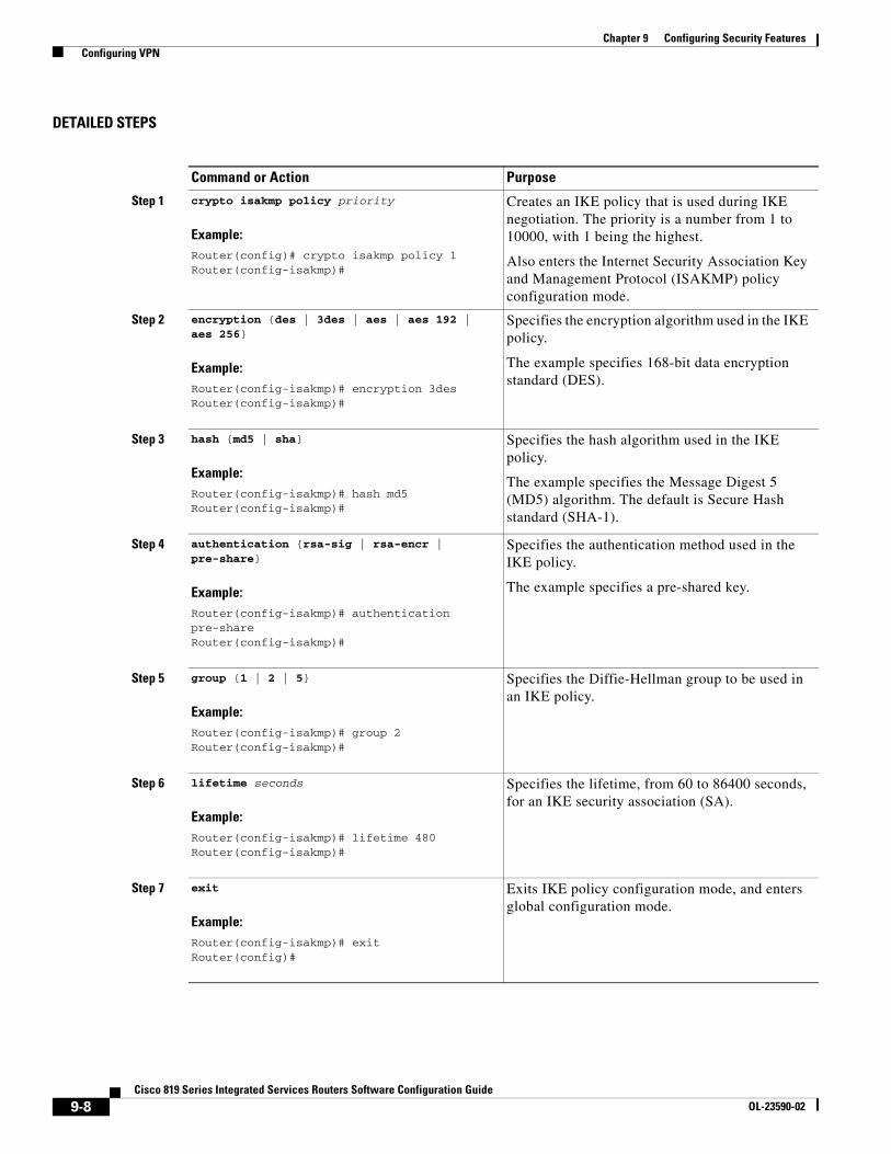
Chapter 9 Configuring Security Features Configuring VPN
DETAILED STEPS
Command or Action Purpose
Step 1 crypto isakmp policy priority
Example:Router(config)# crypto isakmp policy 1Router(config-isakmp)#
Creates an IKE policy that is used during IKE negotiation. The priority is a number from 1 to 10000, with 1 being the highest.
Also enters the Internet Security Association Key and Management Protocol (ISAKMP) policy configuration mode.
Step 2 encryption {des | 3des | aes | aes 192 | aes 256}
Example:Router(config-isakmp)# encryption 3desRouter(config-isakmp)#
Specifies the encryption algorithm used in the IKE policy.
The example specifies 168-bit data encryption standard (DES).
Step 3 hash {md5 | sha}
Example:Router(config-isakmp)# hash md5Router(config-isakmp)#
Specifies the hash algorithm used in the IKE policy.
The example specifies the Message Digest 5 (MD5) algorithm. The default is Secure Hash standard (SHA-1).
Step 4 authentication {rsa-sig | rsa-encr | pre-share}
Example:Router(config-isakmp)# authentication pre-shareRouter(config-isakmp)#
Specifies the authentication method used in the IKE policy.
The example specifies a pre-shared key.
Step 5 group {1 | 2 | 5}
Example:Router(config-isakmp)# group 2Router(config-isakmp)#
Specifies the Diffie-Hellman group to be used in an IKE policy.
Step 6 lifetime seconds
Example:Router(config-isakmp)# lifetime 480Router(config-isakmp)#
Specifies the lifetime, from 60 to 86400 seconds, for an IKE security association (SA).
Step 7 exit
Example:Router(config-isakmp)# exitRouter(config)#
Exits IKE policy configuration mode, and enters global configuration mode.
9-8Cisco 819 Series Integrated Services Routers Software Configuration Guide
OL-23590-02

Chapter 9 Configuring Security Features Configuring VPN
Configure Group Policy Information
To configure the group policy, perform these steps, beginning in global configuration mode:
SUMMARY STEPS
1. crypto isakmp client configuration group {group-name | default}
2. key name
3. dns primary-server
4. domain name
5. exit
6. ip local pool {default | poolname} [low-ip-address [high-ip-address]]
DETAILED STEPS
Command or Action Purpose
Step 1 crypto isakmp client configuration group {group-name | default}
Example:Router(config)# crypto isakmp client configuration group rtr-remoteRouter(config-isakmp-group)#
Creates an IKE policy group containing attributes to be downloaded to the remote client.
Also enters the Internet Security Association Key and Management Protocol (ISAKMP) group policy configuration mode.
Step 2 key name
Example:Router(config-isakmp-group)# key secret-passwordRouter(config-isakmp-group)#
Specifies the IKE pre-shared key for the group policy.
Step 3 dns primary-server
Example:Router(config-isakmp-group)# dns 10.50.10.1Router(config-isakmp-group)#
Specifies the primary Domain Name System (DNS) server for the group.
You may also want to specify Windows Internet Naming Service (WINS) servers for the group by using the wins command.
Step 4 domain name
Example:Router(config-isakmp-group)# domain company.comRouter(config-isakmp-group)#
Specifies group domain membership.
9-9Cisco 819 Series Integrated Services Routers Software Configuration Guide
OL-23590-02

Chapter 9 Configuring Security Features Configuring VPN
Apply Mode Configuration to the Crypto Map
To apply mode configuration to the crypto map, perform these steps, beginning in global configuration mode:
SUMMARY STEPS
1. crypto map map-name isakmp authorization list list-name
2. crypto map tag client configuration address [initiate | respond]
DETAILED STEPS
Step 5 exit
Example:Router(config-isakmp-group)# exitRouter(config)#
Exits IKE group policy configuration mode, and enters global configuration mode.
Step 6 ip local pool {default | pool name} [low-ip-address {high-ip-address]]
Example:Router(config)# ip local pool dynpool 30.30.30.20 30.30.30.30Router(config)#
Specifies a local address pool for the group.
For details about this command and additional parameters that can be set, see Cisco IOS Dial Technologies Command Reference.
Command or Action Purpose
Command or Action Purpose
Step 1 crypto map map-name isakmp authorization list list-name
Example:Router(config)# crypto map dynmap isakmp authorization list rtr-remoteRouter(config)#
Applies mode configuration to the crypto map and enables key lookup (IKE queries) for the group policy from an authentication, authorization, and accounting (AAA) server.
Step 2 crypto map tag client configuration address [initiate | respond]
Example:Router(config)# crypto map dynmap client configuration address respondRouter(config)#
Configures the router to reply to mode configuration requests from remote clients.
9-10Cisco 819 Series Integrated Services Routers Software Configuration Guide
OL-23590-02

Chapter 9 Configuring Security Features Configuring VPN
Enable Policy Lookup
To enable policy lookup through AAA, perform these steps, beginning in global configuration mode:
SUMMARY STEPS
1. aaa new-model
2. aaa authentication login {default | list-name} method1 [method2...]
3. aaa authorization {network | exec | commands level | reverse-access | configuration} {default | list-name} [method1 [method2...]]
4. username name {no password | password password | password encryption-type encrypted-password}
DETAILED STEPS
Command or Action Purpose
Step 1 aaa new-model
Example:Router(config)# aaa new-modelRouter(config)#
Enables the AAA access control model.
Step 2 aaa authentication login {default | list-name} method 1 [method2...]
Example:Router(config)# aaa authentication login rtr-remote localRouter(config)#
Specifies AAA authentication of selected users at login, and specifies the method used.
This example uses a local authentication database. You could also use a RADIUS server for this. For details, see Securing User Services Configuration Guide Library, Cisco IOS Release 12.4T and Cisco IOS Security Command Reference.
Step 3 aaa authorization {network | exec | commands level | reverse-access | configuration} {default | list-name} [method 1 [method2...]
Example:Router(config)# aaa authorization network rtr-remote localRouter(config)#
Specifies AAA authorization of all network-related service requests, including PPP, and specifies the method of authorization.
This example uses a local authorization database. You could also use a RADIUS server for this. For details, see Securing User Services Configuration Guide Library, Cisco IOS Release 12.4T and Cisco IOS Security Command Reference.
Step 4 username name {no password | password password | password encryption-type encrypted-password}
Example:Router(config)# username Cisco password 0 CiscoRouter(config)#
Establishes a username-based authentication system.
This example implements a username of Cisco with an encrypted password of Cisco.
9-11Cisco 819 Series Integrated Services Routers Software Configuration Guide
OL-23590-02

Chapter 9 Configuring Security Features Configuring VPN
Configure IPSec Transforms and Protocols
A transform set represents a certain combination of security protocols and algorithms. During IKE negotiation, the peers agree to use a particular transform set for protecting data flow.
During IKE negotiations, the peers search in multiple transform sets for a transform that is the same at both peers. When a transform set is found that contains such a transform, it is selected and applied to the protected traffic as a part of both peers’ configurations.
To specify the IPSec transform set and protocols, perform these steps, beginning in global configuration mode:
SUMMARY STEPS
1. crypto ipsec profile profile-name
2. crypto ipsec transform-set transform-set-name transform1 [transform2] [transform3] [transform4]
3. crypto ipsec security-association lifetime {seconds seconds | kilobytes kilobytes}
DETAILED STEPS
Configure the IPSec Crypto Method and Parameters
A dynamic crypto map policy processes negotiation requests for new security associations from remote IPSec peers, even if the router does not know all the crypto map parameters (for example, IP address).
To configure the IPSec crypto method, perform these steps, beginning in global configuration mode:
Command or Action Purpose
Step 1 crypto ipsec profile profile-name
Example:Router(config)# crypto ipsec profile pro1Router(config)#
Configures IPSec profile to apply protection on the tunnel for encryption.
Step 2 crypto ipsec transform-set transform-set-name transform1 [transform2] [transform3] [transform4]
Example:Router(config)# crypto ipsec transform-set vpn1 esp-3des esp-sha-hmacRouter(config)#
Defines a transform set—an acceptable combination of IPSec security protocols and algorithms.
See Secure Connectivity Configuration Guide Library, Cisco IOS Release 12.4T for details about the valid transforms and combinations.
Step 3 crypto ipsec security-association lifetime {seconds seconds | kilobytes kilobytes}
Example:Router(config)# crypto ipsec security-association lifetime seconds 86400Router(config)#
Specifies global lifetime values used when IPSec security associations are negotiated.
9-12Cisco 819 Series Integrated Services Routers Software Configuration Guide
OL-23590-02

Chapter 9 Configuring Security Features Configuring VPN
SUMMARY STEPS
1. crypto dynamic-map dynamic-map-name dynamic-seq-num
2. set transform-set transform-set-name [transform-set-name2...transform-set-name6]
3. reverse-route
4. exit
5. crypto map map-name seq-num [ipsec-isakmp] [dynamic dynamic-map-name] [discover] [profile profile-name]
DETAILED STEPS
Command or Action Purpose
Step 1 crypto dynamic-map dynamic-map-name dynamic-seq-num
Example:Router(config)# crypto dynamic-map dynmap 1Router(config-crypto-map)#
Creates a dynamic crypto map entry and enters crypto map configuration mode.
See Cisco IOS Security Command Reference for more details about this command.
Step 2 set transform-set transform-set-name [transform-set-name2...transform-set-name6]
Example:Router(config-crypto-map)# set transform-set vpn1Router(config-crypto-map)#
Specifies which transform sets can be used with the crypto map entry.
Step 3 reverse-route
Example:Router(config-crypto-map)# reverse-routeRouter(config-crypto-map)#
Creates source proxy information for the crypto map entry.
See Cisco IOS Security Command Reference for details.
Step 4 exit
Example:Router(config-crypto-map)# exitRouter(config)#
Returns to global configuration mode.
Step 5 crypto map map-name seq-num [ipsec-isakmp] [dynamic dynamic-map-name] [discover] [profile profile-name]
Example:Router(config)# crypto map static-map 1 ipsec-isakmp dynamic dynmapRouter(config)#
Creates a crypto map profile.
9-13Cisco 819 Series Integrated Services Routers Software Configuration Guide
OL-23590-02
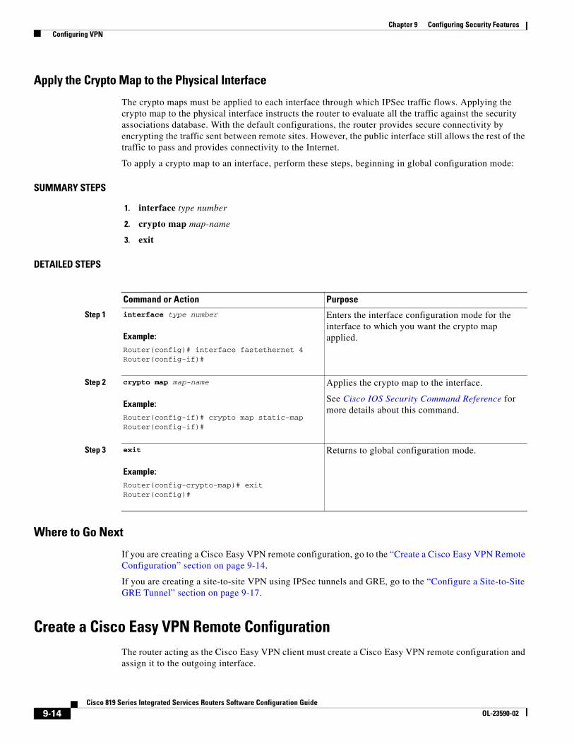
Chapter 9 Configuring Security Features Configuring VPN
Apply the Crypto Map to the Physical Interface
The crypto maps must be applied to each interface through which IPSec traffic flows. Applying the crypto map to the physical interface instructs the router to evaluate all the traffic against the security associations database. With the default configurations, the router provides secure connectivity by encrypting the traffic sent between remote sites. However, the public interface still allows the rest of the traffic to pass and provides connectivity to the Internet.
To apply a crypto map to an interface, perform these steps, beginning in global configuration mode:
SUMMARY STEPS
1. interface type number
2. crypto map map-name
3. exit
DETAILED STEPS
Where to Go Next
If you are creating a Cisco Easy VPN remote configuration, go to the “Create a Cisco Easy VPN Remote Configuration” section on page 9-14.
If you are creating a site-to-site VPN using IPSec tunnels and GRE, go to the “Configure a Site-to-Site GRE Tunnel” section on page 9-17.
Create a Cisco Easy VPN Remote ConfigurationThe router acting as the Cisco Easy VPN client must create a Cisco Easy VPN remote configuration and assign it to the outgoing interface.
Command or Action Purpose
Step 1 interface type number
Example:Router(config)# interface fastethernet 4Router(config-if)#
Enters the interface configuration mode for the interface to which you want the crypto map applied.
Step 2 crypto map map-name
Example:Router(config-if)# crypto map static-mapRouter(config-if)#
Applies the crypto map to the interface.
See Cisco IOS Security Command Reference for more details about this command.
Step 3 exit
Example:Router(config-crypto-map)# exitRouter(config)#
Returns to global configuration mode.
9-14Cisco 819 Series Integrated Services Routers Software Configuration Guide
OL-23590-02

Chapter 9 Configuring Security Features Configuring VPN
To create the remote configuration, perform these steps, beginning in global configuration mode:
SUMMARY STEPS
1. crypto ipsec client ezvpn name
2. group group-name key group-key
3. peer {ip address | hostname}
4. mode {client | network-extension | network extension plus}
5. exit
6. crypto isakmp keepalive seconds
7. interface type number
8. crypto ipsec client ezvpn name [outside | inside]
9. exit
DETAILED STEPS
Command or Action Purpose
Step 1 crypto ipsec client ezvpn name
Example:Router(config)# crypto ipsec client ezvpn ezvpnclientRouter(config-crypto-ezvpn)#
Creates a Cisco Easy VPN remote configuration, and enters Cisco Easy VPN remote configuration mode.
Step 2 group group-name key group-key
Example:Router(config-crypto-ezvpn)# group ezvpnclient key secret-passwordRouter(config-crypto-ezvpn)#
Specifies the IPSec group and IPSec key value for the VPN connection.
Step 3 peer {ip address | hostname}
Example:Router(config-crypto-ezvpn)# peer 192.168.100.1Router(config-crypto-ezvpn)#
Specifies the peer IP address or hostname for the VPN connection.
Note A hostname can be specified only when the router has a DNS server available for hostname resolution.
Note Use this command to configure multiple peers for use as backup. If one peer goes down, the Easy VPN tunnel is established with the second available peer. When the primary peer comes up again, the tunnel is re-established with the primary peer.
9-15Cisco 819 Series Integrated Services Routers Software Configuration Guide
OL-23590-02

Chapter 9 Configuring Security Features Configuring VPN
Configuration Example
The following configuration example shows a portion of the configuration file for the VPN and IPSec tunnel described in this chapter:
!aaa new-model!aaa authentication login rtr-remote localaaa authorization network rtr-remote localaaa session-id common!username Cisco password 0 Cisco
Step 4 mode {client | network-extension | network extension plus}
Example:Router(config-crypto-ezvpn)# mode clientRouter(config-crypto-ezvpn)#
Specifies the VPN mode of operation.
Step 5 exit
Example:Router(config-crypto-ezvpn)# exitRouter(config)#
Returns to global configuration mode.
Step 6 crypto isakmp keepalive seconds
Example:Router(config-crypto-ezvpn)# crypto isakmp keepalive 10Router(config)#
Enables dead peer detection messages. Time between messages is given in seconds, with a range of 10 to 3600.
Step 7 interface type number
Example:Router(config)# interface fastethernet 4Router(config-if)#
Enters the interface configuration mode for the interface to which you want the Cisco Easy VPN remote configuration applied.
Note For routers with an ATM WAN interface, this command would be interface atm 0.
Step 8 crypto ipsec client ezvpn name [outside | inside]
Example:Router(config-if)# crypto ipsec client ezvpn ezvpnclient outsideRouter(config-if)#
Assigns the Cisco Easy VPN remote configuration to the WAN interface, causing the router to automatically create the NAT or port address translation (PAT) and access list configuration needed for the VPN connection.
Step 9 exit
Example:Router(config-crypto-ezvpn)# exitRouter(config)#
Returns to global configuration mode.
Command or Action Purpose
9-16Cisco 819 Series Integrated Services Routers Software Configuration Guide
OL-23590-02

Chapter 9 Configuring Security Features Configuring VPN
!crypto isakmp policy 1
encryption 3desauthentication pre-sharegroup 2lifetime 480
!crypto isakmp client configuration group rtr-remote
key secret-passworddns 10.50.10.1 10.60.10.1domain company.compool dynpool
!crypto ipsec transform-set vpn1 esp-3des esp-sha-hmac!crypto ipsec security-association lifetime seconds 86400!crypto dynamic-map dynmap 1
set transform-set vpn1reverse-route
!crypto map static-map 1 ipsec-isakmp dynamic dynmapcrypto map dynmap isakmp authorization list rtr-remotecrypto map dynmap client configuration address respond
crypto ipsec client ezvpn ezvpnclientconnect autogroup 2 key secret-passwordmode clientpeer 192.168.100.1
!
interface fastethernet 4crypto ipsec client ezvpn ezvpnclient outsidecrypto map static-map
!interface vlan 1
crypto ipsec client ezvpn ezvpnclient inside!
Configure a Site-to-Site GRE TunnelTo configure a GRE tunnel, perform these steps, beginning in global configuration mode:
SUMMARY STEPS
1. interface type number
2. ip address ip-address mask
3. tunnel source interface-type number
4. tunnel destination default-gateway-ip-address
5. crypto map map-name
6. exit
7. ip access-list {standard | extended} access-list-name
8. permit protocol source source-wildcard destination destination-wildcard
9. exit
9-17Cisco 819 Series Integrated Services Routers Software Configuration Guide
OL-23590-02

Chapter 9 Configuring Security Features Configuring VPN
DETAILED STEPS
Command or Action Purpose
Step 1 interface type number
Example:Router(config)# interface tunnel 1Router(config-if)#
Creates a tunnel interface and enters interface configuration mode.
Step 2 ip address ip-address mask
Example:Router(config-if)# 10.62.1.193 255.255.255.252Router(config-if)#
Assigns an address to the tunnel.
Step 3 tunnel source interface-type number
Example:Router(config-if)# tunnel source fastethernet 0Router(config-if)#
Specifies the source endpoint of the router for the GRE tunnel.
Step 4 tunnel destination default-gateway-ip-address
Example:Router(config-if)# tunnel destination 192.168.101.1Router(config-if)#
Specifies the destination endpoint of the router for the GRE tunnel.
Step 5 crypto map map-name
Example:Router(config-if)# crypto map static-mapRouter(config-if)#
Assigns a crypto map to the tunnel.
Note Dynamic routing or static routes to the tunnel interface must be configured to establish connectivity between the sites.
Step 6 exit
Example:Router(config-if)# exitRouter(config)#
Exits interface configuration mode, and returns to global configuration mode.
Step 7 ip access-list {standard | extended} access-list-name
Example:Router(config)# ip access-list extended vpnstatic1Router(config-acl)#
Enters ACL configuration mode for the named ACL that is used by the crypto map.
9-18Cisco 819 Series Integrated Services Routers Software Configuration Guide
OL-23590-02

Chapter 9 Configuring Security Features Configuring VPN
Configuration Example
The following configuration example shows a portion of the configuration file for a VPN using a GRE tunnel scenario described in the preceding sections:
!aaa new-model!aaa authentication login rtr-remote localaaa authorization network rtr-remote localaaa session-id common!username cisco password 0 cisco!interface tunnel 1
ip address 10.62.1.193 255.255.255.252
tunnel source fastethernet 0
tunnel destination interface 192.168.101.1
ip route 20.20.20.0 255.255.255.0 tunnel 1
crypto isakmp policy 1encryption 3desauthentication pre-sharegroup 2
!crypto isakmp client configuration group rtr-remote
key secret-passworddns 10.50.10.1 10.60.10.1domain company.compool dynpool
!crypto ipsec transform-set vpn1 esp-3des esp-sha-hmac!crypto ipsec security-association lifetime seconds 86400!crypto dynamic-map dynmap 1
set transform-set vpn1reverse-route
!crypto map static-map 1 ipsec-isakmp dynamic dynmap
Step 8 permit protocol source source-wildcard destination destination-wildcard
Example:Router(config-acl)# permit gre host 192.168.100.1 host 192.168.101.1Router(config-acl)#
Specifies that only GRE traffic is permitted on the outbound interface.
Step 9 exit
Example:Router(config-acl)# exitRouter(config)#
Returns to global configuration mode.
Command or Action Purpose
9-19Cisco 819 Series Integrated Services Routers Software Configuration Guide
OL-23590-02

Chapter 9 Configuring Security Features Configuring VPN
crypto map dynmap isakmp authorization list rtr-remotecrypto map dynmap client configuration address respond!! Defines the key association and authentication for IPsec tunnel.crypto isakmp policy 1 hash md5 authentication pre-sharecrypto isakmp key cisco123 address 200.1.1.1!!! Defines encryption and transform set for the IPsec tunnel.crypto ipsec transform-set set1 esp-3des esp-md5-hmac !! Associates all crypto values and peering address for the IPsec tunnel.crypto map to_corporate 1 ipsec-isakmp set peer 200.1.1.1 set transform-set set1 match address 105!!! VLAN 1 is the internal home network.interface vlan 1 ip address 10.1.1.1 255.255.255.0 ip nat inside ip inspect firewall in ! Inspection examines outbound traffic.crypto map static-mapno cdp enable
!! FE4 is the outside or Internet-exposed interfaceinterface fastethernet 4 ip address 210.110.101.21 255.255.255.0 ! acl 103 permits IPsec traffic from the corp. router as well as ! denies Internet-initiated traffic inbound. ip access-group 103 in ip nat outside no cdp enable crypto map to_corporate ! Applies the IPsec tunnel to the outside interface.!! Utilize NAT overload in order to make best use of the ! single address provided by the ISP.ip nat inside source list 102 interface Ethernet1 overloadip classlessip route 0.0.0.0 0.0.0.0 210.110.101.1no ip http server!!! acl 102 associated addresses used for NAT.access-list 102 permit ip 10.1.1.0 0.0.0.255 any! acl 103 defines traffic allowed from the peer for the IPsec tunnel.access-list 103 permit udp host 200.1.1.1 any eq isakmpaccess-list 103 permit udp host 200.1.1.1 eq isakmp anyaccess-list 103 permit esp host 200.1.1.1 any! Allow ICMP for debugging but should be disabled because of security implications.access-list 103 permit icmp any any access-list 103 deny ip any any ! Prevents Internet-initiated traffic inbound.! acl 105 matches addresses for the IPsec tunnel to or from the corporate network.access-list 105 permit ip 10.1.1.0 0.0.0.255 192.168.0.0 0.0.255.255no cdp run
9-20Cisco 819 Series Integrated Services Routers Software Configuration Guide
OL-23590-02

Cisco 819 Series IntegraOL-23590-02
C H A P T E R 10
Configuring the Ethernet SwitchesThis chapter gives an overview of configuration tasks for the 4-port Fast Ethernet (FE) switch and for the Gigabit Ethernet (GE) switch that services the embedded wireless access point on the Cisco 819 Integrated Services Routers (ISRs).
The FE switches are 10/100Base T Layer 2 Fast Ethernet switches. Traffic between different VLANs on a switch is routed through the router platform with the switched virtual interface (SVI).
The GE switch is a 1000Base T Layer 2 Gigabit Ethernet switch, the internal interface between the router and its embedded wireless access point.
Any switch port may be configured as a trunking port to connect to other Cisco Ethernet switches.
This chapter contains the following sections:
• Switch Port Numbering and Naming, page 10-1
• Restrictions for the FE Switch, page 10-1
• Information About Ethernet Switches, page 10-2
• Overview of SNMP MIBs, page 10-3
• How to Configure Ethernet Switches, page 10-6
Switch Port Numbering and NamingThe ports on the FE switch are numbered FE0 through FE3. The port on the GE switch is named and numbered Wlan-GigabitEthernet0.
Restrictions for the FE SwitchThe following restrictions apply to the FE switch:
• The ports of an FE switch must NOT be connected to any Fast Ethernet onboard port of the router.
• Inline power is not supported on Cisco 819 ISRs.
• VTP pruning is not supported.
• The FE switch can support up to 200 secure MAC addresses.
10-1ted Services Routers Software Configuration Guide

Chapter 10 Configuring the Ethernet Switches Information About Ethernet Switches
Information About Ethernet SwitchesTo configure Ethernet switches, you should understand the following concept:
• VLANs and VLAN Trunk Protocol, page 10-2
• Layer 2 Ethernet Switching, page 10-2
• 802.1x Authentication, page 10-2
• Spanning Tree Protocol, page 10-2
• Cisco Discovery Protocol, page 10-2
• Switched Port Analyzer, page 10-3
• IGMP Snooping, page 10-3
• Storm Control, page 10-3
• Fallback Bridging, page 10-3
VLANs and VLAN Trunk ProtocolFor information on the concept of VLANs and VLAN Trunk Protocol (VTP), see VLANs.
Layer 2 Ethernet SwitchingFor information on the concept of Layer 2 Ethernet Switching, see Layer 2 Ethernet Switching.
802.1x AuthenticationFor information on the concept of 802.1x Authentication, see 802.1x Authentication.
Spanning Tree ProtocolFor information on the concept of Spanning Tree Protocol, see Using the Spanning Tree Protocol with the Cisco EtherSwitch Network Module.
Cisco Discovery ProtocolCisco Discovery Protocol (CDP) runs over Layer 2 (the data link layer) on all Cisco routers, bridges, access servers, and switches. CDP allows network management applications to discover Cisco devices that are neighbors of already known devices, in particular, neighbors running lower-layer, transparent protocols. With CDP, network management applications can learn the device type and the SNMP agent address of neighboring devices. This feature enables applications to send SNMP queries to neighboring devices.
10-2Cisco 819 Series Integrated Services Routers Software Configuration Guide
OL-23590-02

Chapter 10 Configuring the Ethernet Switches Overview of SNMP MIBs
CDP runs on all LAN and WAN media that support Subnetwork Access Protocol (SNAP). Each CDP-configured device sends periodic messages to a multicast address. Each device advertises at least one address at which it can receive SNMP messages. The advertisements also contain the time-to-live, or hold-time information, which indicates the length of time a receiving device should hold CDP information before discarding it.
Switched Port AnalyzerFor information on the concept of Switched Port Analyzer, see Switched Port Analyzer.
IGMP SnoopingFor information on the concept of IGMP Snooping, see IGMP Snooping.
IGMP Version 3
The Cisco 819 ISRs support Version 3 of IGMP snooping.
IGMPv3 provides supports for source filtering, which enables a multicast receiver host to signal to a router which groups the receiver host wants to receive multicast traffic from, and from which sources this traffic is expected. Enabling the IGMPv3 feature with IGMP snooping on Cisco ISRs provides Basic IGMPv3 Snooping Support (BISS). BISS provides constrained flooding of multicast traffic in the presence of IGMPv3 hosts. This support constrains traffic to approximately the same set of ports as IGMPv2 snooping does with IGMPv2 hosts. The constrained flooding only considers the destination multicast address.
Storm ControlFor information on the concept of storm control, see Storm Control.
Fallback BridgingFor information on the concept of fallback bridging, see Fallback Bridging.
Overview of SNMP MIBsSimple Management Network Protocol (SNMP) development and use is centered around the Management Information Base (MIB). An SNMP MIB is an abstract data base and it is a conceptual specification for information that a management application may read and modify in a certain form. This does not imply that the information is kept in the managed system in that same form. The SNMP agent translates between the internal data structures and formats of the managed system and the external data structures and formats defined for the MIB.
The SNMP MIB is conceptually a tree structure with conceptual tables. Cisco Layer 2 Switching Interface MIB is discussed in more detail in the next section. Relative to this tree structure, the term MIB is used in two senses. In one sense, it is actually a MIB branch, usually containing information for a single aspect of technology, such as a transmission medium or a routing protocol. A MIB used in this
10-3Cisco 819 Series Integrated Services Routers Software Configuration Guide
OL-23590-02

Chapter 10 Configuring the Ethernet Switches Overview of SNMP MIBs
sense is more accurately called a MIB module and is usually defined in a single document. In the other sense, a MIB is a collection of such branches. Such a collection might comprise, for example, all the MIB modules implemented by a given agent, or the entire collection of MIB modules defined for SNMP.
A MIB is a tree where the leaves are individual items of data called objects. An object may be, for example, a counter or a protocol status. MIB objects are also sometimes called variables.
For a list of MIBs supported on Cisco 819 4G LTE routers, see the “SNMP MIBs” section of Configuring Cisco 4G LTE Wireless WAN EHWIC.
MIBs were modified in IOS release 15.2(4)M1 to support Cisco 819HGW and Cisco 819HWD SKUs. Table 10-1 lists the MIBs for Cisco 819 ISRs.
BRIDGE-MIB for Layer 2 Ethernet Switching The Layer 2 Ethernet Switching Interface BRIDGE-MIB is supported in the Cisco 819 platforms. The BRIDGE-MIB enables the user to know the Media Access Control (MAC) addresses and spanning tree information of the Ethernet switch modules. The user can query the MIB agent using the SNMP protocol and get the details of Ethernet switch modules such as MAC addresses of each interfaces and spanning protocol information.
The Bridge-MIB uses the following approaches to get the L2 layers BRIDGE-MIB information:
• Community-string-based approach
• Context-based approach
In the community-string-based approach, one community string is created for each VLAN. Based on the query, the respective VLAN MIB is displayed.
To get the BRIDGE-MIB details, use the snmp-server community public RW command in the configuration mode.
Router(config)#snmp-server community public RW
Table 10-1 MIBs for Cisco 819 ISRs
MIBs MIBs Link
CISCO-PRODUCTS-MIB To locate and download MIBs for selected platforms, Cisco IOS releases, and feature sets, use Cisco MIB Locator found at the following URL:
http://tools.cisco.com/ITDIT/MIBS/servlet/index
CISCO-ENTITY-VENDORTYPE-OID-MIB
OLD-CISCO-CHASSIS-MIB
CISCO-WAN-3G-MIB
10-4Cisco 819 Series Integrated Services Routers Software Configuration Guide
OL-23590-02

Chapter 10 Configuring the Ethernet Switches Overview of SNMP MIBs
Use the following syntax to query the SNMP BRIDGE-MIB details:
snmpwalk -v2c <ip address of the ISR, …> public .1.3.6.1.2.1.17snmpwalk -v2c <ip address of the ISR, …> public@2 .1.3.6.1.2.1.17snmpwalk -v2c <ip address of the ISR, …> public@3 .1.3.6.1.2.1.17
Note When you create a VLAN ‘x’, the logical entity public@x is added. If you query with public community, the L3 MIB is displayed. When you query with public@x, the L2 MIB for VLAN ‘x’ is displayed.
In the context-based approach, the SNMP context mapping commands are used to display the values for L2 interfaces. Each VLAN is mapped to a context. When the user queries with a context, the MIB displays the data for that specific VLAN, which is mapped to the context. In this approach, each VLAN is manually mapped to a context.
To get the BRIDGE-MIB details, use the following commands in the configuration mode:
Router(config)#Routersnmp-server group public v2c context bridge-groupRouter(config)#snmp-server community public RWRouter(config)#snmp-server community private RWRouter(config)#snmp-server context bridge-groupRouter(config)#snmp mib community-map public context bridge-group
Use the following syntax to query the SNMP BRIDGE-MIB details:
snmpwalk -v2c <ip address of the ISR, …> public@1 .1.3.6.1.2.1.17 ?L2-MIBsnmpwalk -v2c <ip address of the ISR, …> private .1.3.6.1.2.1.17?L3-MIB
Note When you query with the public community, the L2 MIB is displayed. Use private group for L3 MIB.
For more details to configure and retrieve the BRIDGE-MIB details, see The BRIDGE-MIB.
MAC Address NotificationMAC address notification enables you to track users on a network by storing the MAC address activity on the switch. Whenever the switch learns or removes a MAC address, an SNMP notification can be generated and sent to the NMS. If you have many users coming and going from the network, you can set a trap interval time to bundle the notification traps and reduce network traffic. The MAC notification history table stores the MAC address activity for each hardware port for which the trap is enabled. MAC address notifications are generated for dynamic and secure MAC addresses; events are not generated for self addresses, multicast addresses, or other static addresses.
For more details to configure MAC address notification, see Configuring MAC Address Notification Traps.
10-5Cisco 819 Series Integrated Services Routers Software Configuration Guide
OL-23590-02

Chapter 10 Configuring the Ethernet Switches How to Configure Ethernet Switches
How to Configure Ethernet SwitchesSee the following sections for configuration tasks for Ethernet switches.
• Configuring VLANs, page 10-6
• Configuring Layer 2 Interfaces, page 10-7
• Configuring 802.1x Authentication, page 10-8
• Configuring Spanning Tree Protocol, page 10-8
• Configuring MAC Table Manipulation, page 10-9
• Configuring Cisco Discovery Protocol, page 10-9
• Configuring the Switched Port Analyzer, page 10-10
• Configuring IP Multicast Layer 3 Switching, page 10-10
• Configuring IGMP Snooping, page 10-10
• Configuring Per-Port Storm Control, page 10-10
• Configuring Fallback Bridging, page 10-11
• Managing the Switch, page 10-12
Configuring VLANs This section provides information on how to configure VLANs. The Cisco 819 ISRs support 2 VLANs and the Cisco 819 ISRs support 8 VLANs.
• VLANs on the FE Ports, page 10-6
• VLANs on the GE Port, page 10-7
VLANs on the FE Ports
Perform these steps to configure VLANs, beginning in configuration mode.
Command Purpose
Step 1 interface fe port Selects the Fast Ethernet port to configure.
Step 2 shutdown (Optional) Shuts down the interface to prevent traffic flow until configuration is complete.
10-6Cisco 819 Series Integrated Services Routers Software Configuration Guide
OL-23590-02

Chapter 10 Configuring the Ethernet Switches How to Configure Ethernet Switches
For additional information, see Layer 2 LAN Ports.
VLANs on the GE Port
Because the GE port is an internal interface that services only the router’s embedded access point, it cannot be configured only with the command switchport access vlan X, where X is other than 1. It may, however, be configured in trunk mode. This may be done by performing the following steps, beginning in configuration mode.
Configuring Layer 2 InterfacesFor information on how to configure Layer 2 interfaces, see Configuring Layer 2 Interfaces.
Step 3 switchport Configures the Fast Ethernet port for Layer 2 switching.
Note You must enter the switchport command once without any keywords to configure the Fast Ethernet port as a Layer 2 port before you can enter additional switchport commands with keywords. This command creats a Cisco default VLAN.
This configuration sets the default trunking administrative mode to switchport mode dynamic desirable and the trunk encapsulation to negotiate.
By default, all VLANs created are included in the default trunk.
Step 4 switchport access vlan vlan_id Creates instances of additional VLANs. Allowable values of vlan_id are 2 to 4094, except for reserved values of 1002 to 1005.
Step 5 no shutdown Activates the interface.
Step 6 end Exits configuration mode.
Command Purpose
Comand Purpose
Step 1 interface Wlan-GigabitEthernet0 Selects the Gigabit Ethernet port to configure.
Step 2 switchport mode trunk Places the port in trunk mode.
Step 3 switchport access vlan vlan_id (Optional) Once the port is in trunk mode, it may be assigned a VLAN number other than 1.
10-7Cisco 819 Series Integrated Services Routers Software Configuration Guide
OL-23590-02
Chapter 10 Configuring the Ethernet Switches How to Configure Ethernet Switches
This section contains information on the following topics:
• Configuring a range of interfaces
• Defining a range macro
• Configuring Layer 2 optional interface features
Configuring 802.1x AuthenticationFor information on how to configure 802.1x port-based authentication, see Configuring IEEE 802.1x Port-Based Authentication.
This section contains information on the following topics:
• Understanding the default 802.1x configuration
• Enabling 802.1x Authentication
• Configuring the switch-to-RADIUS-server comunication
• Enabling periodic reauthentication
• Changing the quiet period
• Changing the switch-to-client retransmission time
• Setting the switch-to-client frame-retransmission number
• Enabling multiple hosts
• Resetting the 802.1x configuration to default values
• Displaying 802.1x statistics and status
Configuring Spanning Tree ProtocolFor information on how to configure Spanning Tree Protocol, see Configuring Spanning Tree.
This section contains information on the following topics:
• Enabling spanning tree
• Configuring spanning tree port priority
• Configuring spanning tree port cost
• Configuring the bridge priority of a VLAN
• Configuring the Hello Time
• Configuring the forward-delay time for a VLAN
• Configuring the maximum aging time for a VLAN
• Disabling spanning tree
10-8Cisco 819 Series Integrated Services Routers Software Configuration Guide
OL-23590-02

Chapter 10 Configuring the Ethernet Switches How to Configure Ethernet Switches
Configuring MAC Table ManipulationFor information on how to configure MAC table manipulation, see Configuring MAC Table Manipulation.
Port Security
The topic of enabling known MAC address traffic deals with port security. Port security can be either static or dynamic.
Static port security allows the user to specify which devices are allowed access through a given switch port. The specification is done manually by placing allowed device MAC addresses in the MAC address table. Static port security is also known as MAC address filtering.
Dynamic port security is similar. However, instead of specifying the MAC address of the devices, the user specifies the maximum number of devices that will be allowed on the port. If the maximum number specified is more than the number of MAC addresses specified manually, the switch will learn the MAC address automatically, up to the maximum specified. If the maximum number specified is less than the number of MAC addresess already specified statically, an error message will be produced.
The following command is used to specify static or dynamic port security.
Configuring Cisco Discovery ProtocolFor information on how to configure Cisco Discovery Protocol (CDP), see Configuring Cisco Discovery Protocol.
This section contains information on the following topics:
• Enabling CDP
• Enabling CDP on an interface
• Monitoring and maintaining CDP
Command Purpose
Router(config)# mac-address-table secure [<mac-address> | maximum maximum addresses] fastethernet interface-id [vlan <vlan id>]
<mac-address> enables static port security. Use of the keyword maximum enables dynamic port security.
10-9Cisco 819 Series Integrated Services Routers Software Configuration Guide
OL-23590-02

Chapter 10 Configuring the Ethernet Switches How to Configure Ethernet Switches
Configuring the Switched Port AnalyzerFor information on how to configure a switched port analyzer (SPAN) session, see Configuring the Switched Port Analyzer (SPAN).
This section contains information on the following topics:
• Configuring the SPAN sources
• Configuring SPAN destinations
• Verifying the SPAN session
• Removing sources or destinations from a SPAN session
Configuring IP Multicast Layer 3 SwitchingFor information on how to configure IP multicast Layer 3 switching, see Configuring IP Multicast Layer 3 Switching.
This section contains information on the following topics:
• Enabling IP multicast routing globally
• Enabling IP protocol-independent multicast (PIM) on Layer 3 interfaces
• Verifying IP multicast Layer 3 hardware switching summary
• Verifying the IP multicast routing table
Configuring IGMP SnoopingFor information on how to configure IGMP snooping, see Configuring IGMP Snooping.
This section contains information on the following topics:
• Enabling or disabling IGMP snooping
• Enabling IGMP immediate-leave processing
• Statically configuring an interface to join a group
• Configuring a multicast router port
IGMP Version 3
In support of the IGMPv3 feature in Cisco IOS Release 12.4(15)T, the groups and count keywords were added to the show ip igmp snooping command, and the output of the show ip igmp snooping command was modified to include global information about IGMP snooping groups. Use the show ip igmp snooping command with the groups keyword to display the multicast table learned by IGMP snooping for all VLANs or the show ip igmp snooping command with the groups keyword, vlan-id keyword, and vlan-id argument to display the multicast table learned by IGMP snooping for a specific VLAN. Use the show ip igmp snooping command with the groups and count keywords to display the number of multicast groups learned by IGMP snooping.
Configuring Per-Port Storm ControlFor information on how to configure per-port storm control, see Configuring Per-Port Storm-Control.
10-10Cisco 819 Series Integrated Services Routers Software Configuration Guide
OL-23590-02

Chapter 10 Configuring the Ethernet Switches How to Configure Ethernet Switches
This section contains information on the following topics:
• Enabling per-port storm-control
• Disabling per-port storm-control
Configuring Fallback BridgingFor information on how to configure fallback bridging, see Configuring Fallback Bridging.
This section contains information on the following topics:
• Understanding the default fallback bridging configuration
• Creating a bridge group
• Preventing the forwarding of dynamically learned stations
• Configuring the bridge table aging time
• Filtering frames by a specific MAC address
• Adjusting spanning-tree parameters
• Monitoring and maintaining the network
10-11Cisco 819 Series Integrated Services Routers Software Configuration Guide
OL-23590-02

Chapter 10 Configuring the Ethernet Switches How to Configure Ethernet Switches
Managing the SwitchFor information on management of the switch, see Managing the EtherSwitch HWIC.
This section contains information on the following topics:
• Adding Trap Managers
• Configuring IP Information
• Enabling Switch Port Analyzer
• Managing the ARP Table
• Managing the MAC Address Tables
• Removing Dynamic Addresses
• Adding Secure Addresses
• Configuring Static Addresses
• Clearing all MAC Address Tables
10-12Cisco 819 Series Integrated Services Routers Software Configuration Guide
OL-23590-02

Cisco 819 Series IntegraOL-23590-02
C H A P T E R 11
Configuring PPP over Ethernet with NATThis chapter provides an overview of Point-to-Point Protocol over Ethernet (PPPoE) clients and Network Address Translation (NAT) that can be configured on the Cisco 819 Integrated Services Routers (ISRs).
Multiple PCs can be connected to the LAN behind the router. Before the traffic from these PCs is sent to the PPPoE session, it can be encrypted, filtered, and so forth. Figure 11-1 shows a typical deployment scenario with a PPPoE client and NAT configured on the Cisco router.
Figure 11-1 PPP over Ethernet with NAT
1217
53
2
3
5
6
1
7
4
Internet
1 Multiple networked devices—Desktops, laptop PCs, switches
2 Fast Ethernet LAN interface (inside interface for NAT)
3 PPPoE client—Cisco 819 ISRs
4 Point at which NAT occurs
5 Fast Ethernet WAN interface (outside interface for NAT)
6 Cable modem or other server that is connected to the Internet
7 PPPoE session between the client and a PPPoE server
11-1ted Services Routers Software Configuration Guide

Chapter 11 Configuring PPP over Ethernet with NAT Configure the Virtual Private Dialup Network Group Number
PPPoE
The PPPoE Client feature on the router provides PPPoE client support on Ethernet interfaces. A dialer interface must be used for cloning virtual access. Multiple PPPoE client sessions can be configured on an Ethernet interface, but each session must use a separate dialer interface and a separate dialer pool.
A PPPoE session is initiated on the client side by the Cisco 819 ISRs. An established PPPoE client session can be terminated in one of two ways:
• By entering the clear vpdn tunnel pppoe command. The PPPoE client session terminates, and the PPPoE client immediately tries to reestablish the session. This also occurs if the session has a timeout.
• By entering the no pppoe-client dial-pool number command to clear the session. The PPPoE client does not attempt to re-establish the session.
NAT
NAT (represented as the dashed line at the edge of the Cisco router) signifies two addressing domains and the inside source address. The source list defines how the packet travels through the network.
Configuration Tasks
Perform the following tasks to configure this network scenario:
• Configure the Virtual Private Dialup Network Group Number, page 11-2
• Configure the Fast Ethernet WAN Interfaces, page 11-3
• Configure the Dialer Interface, page 11-4
• Configure Network Address Translation, page 11-6
An example showing the results of these configuration tasks is shown in the “Configuration Example” section on page 11-9.
Configure the Virtual Private Dialup Network Group NumberConfiguring a virtual private dialup network (VPDN) enables multiple clients to communicate through the router by way of a single IP address.
Complete the following steps to configure a VPDN, starting from the global configuration mode.
SUMMARY STEPS
1. vpdn enable
2. vpdn-group name
3. request-dialin
4. protocol {l2tp | pppoe}
5. exit
6. exit
11-2Cisco 819 Series Integrated Services Routers Software Configuration Guide
OL-23590-02
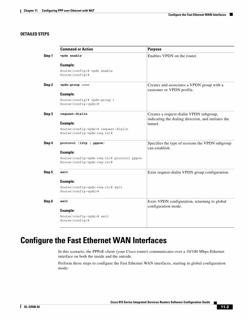
Chapter 11 Configuring PPP over Ethernet with NAT Configure the Fast Ethernet WAN Interfaces
DETAILED STEPS
Configure the Fast Ethernet WAN InterfacesIn this scenario, the PPPoE client (your Cisco router) communicates over a 10/100 Mbps-Ethernet interface on both the inside and the outside.
Perform these steps to configure the Fast Ethernet WAN interfaces, starting in global configuration mode:
Command or Action Purpose
Step 1 vpdn enable
Example:Router(config)# vpdn enableRouter(config)#
Enables VPDN on the router.
Step 2 vpdn-group name
Example:Router(config)# vpdn-group 1Router(config-vpdn)#
Creates and associates a VPDN group with a customer or VPDN profile.
Step 3 request-dialin
Example:Router(config-vpdn)# request-dialinRouter(config-vpdn-req-in)#
Creates a request-dialin VPDN subgroup, indicating the dialing direction, and initiates the tunnel.
Step 4 protocol {l2tp | pppoe}
Example:Router(config-vpdn-req-in)# protocol pppoeRouter(config-vpdn-req-in)#
Specifies the type of sessions the VPDN subgroup can establish.
Step 5 exit
Example:Router(config-vpdn-req-in)# exitRouter(config-vpdn)#
Exits request-dialin VPDN group configuration.
Step 6 exit
Example:Router(config-vpdn)# exitRouter(config)#
Exits VPDN configuration, returning to global configuration mode.
11-3Cisco 819 Series Integrated Services Routers Software Configuration Guide
OL-23590-02

Chapter 11 Configuring PPP over Ethernet with NAT Configure the Dialer Interface
SUMMARY STEPS
1. interface type number
2. pppoe-client dial-pool-number number
3. no shutdown
4. exit
Configure the Dialer InterfaceThe dialer interface indicates how to handle traffic from the clients, including, for example, default routing information, the encapsulation protocol, and the dialer pool to use. The dialer interface is also used for cloning virtual access. Multiple PPPoE client sessions can be configured on a Fast Ethernet interface, but each session must use a separate dialer interface and a separate dialer pool.
Complete the following steps to configure a dialer interface for one of the Fast Ethernet LAN interfaces on the router, starting in global configuration mode.
Command Purpose
Step 1 interface type number
Example:Router(config)# interface fastethernet 4Router(config-if)#
Enters interface configuration mode for a Fast Ethernet WAN interface.
Step 2 pppoe-client dial-pool-number number
Example:Router(config-if)# pppoe-client dial-pool-number 1Router(config-if)#
Configures the PPPoE client and specifies the dialer interface to use for cloning.
Step 3 no shutdown
Example:Router(config-if)# no shutdownRouter(config-if)#
Enables the Fast Ethernet interface and the configuration changes just made to it.
Step 4 exit
Example:Router(config-if)# exitRouter(config)#
Exits configuration mode for the Fast Ethernet interface and returns to global configuration mode.
11-4Cisco 819 Series Integrated Services Routers Software Configuration Guide
OL-23590-02

Chapter 11 Configuring PPP over Ethernet with NAT Configure the Dialer Interface
SUMMARY STEPS
1. interface dialer dialer-rotary-group-number
2. ip address negotiated
3. ip mtu bytes
4. encapsulation encapsulation-type
5. ppp authentication {protocol1 [protocol2...]}
6. dialer pool number
7. dialer-group group-number
8. exit
9. dialer-list dialer-group protocol protocol-name {permit | deny | list access-list-number | access-group}
10. ip route prefix mask {interface-type interface-number}
DETAILED STEPS
Command Purpose
Step 1 interface dialer dialer-rotary-group-number
Example:Router(config)# interface dialer 0Router(config-if)#
Creates a dialer interface (numbered 0 to 255), and enters interface configuration mode.
Step 2 ip address negotiated
Example:Router(config-if)# ip address negotiatedRouter(config-if)#
Specifies that the IP address for the interface is obtained through PPP/IPCP (IP Control Protocol) address negotiation.
Step 3 ip mtu bytes
Example:Router(config-if)# ip mtu 1492Router(config-if)#
Sets the size of the IP maximum transmission unit (MTU). The default minimum is 128 bytes. The maximum for Ethernet is 1492 bytes.
Step 4 encapsulation encapsulation-type
Example:Router(config-if)# encapsulation pppRouter(config-if)#
Sets the encapsulation type to PPP for the data packets being transmitted and received.
Step 5 ppp authentication {protocol1 [protocol2...]}
Example:Router(config-if)# ppp authentication chapRouter(config-if)#
Sets the PPP authentication method to Challenge Handshake Authentication Protocol (CHAP).
For details about this command and additional parameters that can be set, see Cisco IOS Security Command Reference.
11-5Cisco 819 Series Integrated Services Routers Software Configuration Guide
OL-23590-02
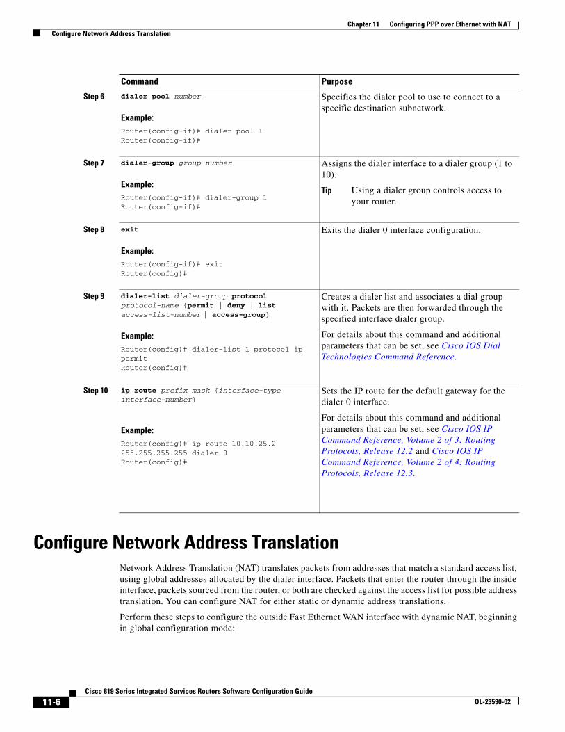
Chapter 11 Configuring PPP over Ethernet with NAT Configure Network Address Translation
Configure Network Address TranslationNetwork Address Translation (NAT) translates packets from addresses that match a standard access list, using global addresses allocated by the dialer interface. Packets that enter the router through the inside interface, packets sourced from the router, or both are checked against the access list for possible address translation. You can configure NAT for either static or dynamic address translations.
Perform these steps to configure the outside Fast Ethernet WAN interface with dynamic NAT, beginning in global configuration mode:
Step 6 dialer pool number
Example:Router(config-if)# dialer pool 1Router(config-if)#
Specifies the dialer pool to use to connect to a specific destination subnetwork.
Step 7 dialer-group group-number
Example:Router(config-if)# dialer-group 1Router(config-if)#
Assigns the dialer interface to a dialer group (1 to 10).
Tip Using a dialer group controls access to your router.
Step 8 exit
Example:Router(config-if)# exitRouter(config)#
Exits the dialer 0 interface configuration.
Step 9 dialer-list dialer-group protocol protocol-name {permit | deny | list access-list-number | access-group}
Example:Router(config)# dialer-list 1 protocol ip permitRouter(config)#
Creates a dialer list and associates a dial group with it. Packets are then forwarded through the specified interface dialer group.
For details about this command and additional parameters that can be set, see Cisco IOS Dial Technologies Command Reference.
Step 10 ip route prefix mask {interface-type interface-number}
Example:Router(config)# ip route 10.10.25.2 255.255.255.255 dialer 0Router(config)#
Sets the IP route for the default gateway for the dialer 0 interface.
For details about this command and additional parameters that can be set, see Cisco IOS IP Command Reference, Volume 2 of 3: Routing Protocols, Release 12.2 and Cisco IOS IP Command Reference, Volume 2 of 4: Routing Protocols, Release 12.3.
Command Purpose
11-6Cisco 819 Series Integrated Services Routers Software Configuration Guide
OL-23590-02

Chapter 11 Configuring PPP over Ethernet with NAT Configure Network Address Translation
SUMMARY STEPS
1. ip nat pool name start-ip end-ip {netmask netmask | prefix-length prefix-length}
2. ip nat inside source {list access-list-number} {interface type number | pool name} [overload]
3. interface type number
4. ip nat {inside | outside}
5. no shutdown
6. exit
7. interface type number
8. ip nat {inside | outside}
9. no shutdown
10. exit
11. access-list access-list-number {deny | permit} source [source-wildcard]
11-7Cisco 819 Series Integrated Services Routers Software Configuration Guide
OL-23590-02

Chapter 11 Configuring PPP over Ethernet with NAT Configure Network Address Translation
DETAILED STEPS
Command Purpose
Step 1 ip nat pool name start-ip end-ip {netmask netmask | prefix-length prefix-length}
Example:Router(config)# ip nat pool pool1 192.168.1.0 192.168.2.0 netmask 255.255.252.0Router(config)#
Creates pool of global IP addresses for NAT.
Step 2 ip nat inside source {list access-list-number} {interface type number | pool name} [overload]
Example:Router(config)# ip nat inside source list 1 interface dialer 0 overload
or
Example:Router(config)# ip nat inside source list acl1 pool pool1
Enables dynamic translation of addresses on the inside interface.
The first example shows the addresses permitted by the access list 1 to be translated to one of the addresses specified in the dialer interface 0.
The second example shows the addresses permitted by access list acl1 to be translated to one of the addresses specified in the NAT pool pool1.
For details about this command and additional parameters that can be set, as well as information about enabling static translation, see Cisco IOS IP Command Reference, Volume 1 of 4: Addressing and Services.
Step 3 interface type number
Example:Router(config)# interface vlan 1Router(config-if)#
Enters configuration mode for the VLAN (on which the Fast Ethernet LAN interfaces [FE0–FE3] reside) to be the inside interface for NAT.
Step 4 ip nat {inside | outside}
Example:Router(config-if)# ip nat insideRouter(config-if)#
Identifies the specified VLAN interface as the NAT inside interface.
For details about this command and additional parameters that can be set, as well as information about enabling static translation, see Cisco IOS IP Command Reference, Volume 1 of 4: Addressing and Services.
Step 5 no shutdown
Example:Router(config-if)# no shutdownRouter(config-if)#
Enables the configuration changes just made to the Ethernet interface.
Step 6 exit
Example:Router(config-if)# exitRouter(config)#
Exits configuration mode for the Fast Ethernet interface.
11-8Cisco 819 Series Integrated Services Routers Software Configuration Guide
OL-23590-02

Chapter 11 Configuring PPP over Ethernet with NAT Configuration Example
Note If you want to use NAT with a virtual-template interface, you must configure a loopback interface. See the “Basic Router Configuration” section on page 5-1 for information on configuring a loopback interface.
For complete information on the NAT commands, see the Cisco IOS Release 12.3 documentation set. For more general information on NAT concept, see “Cisco IOS Software Basic Skills” section on page A-1.
Configuration ExampleThe following configuration example shows a portion of the configuration file for the PPPoE scenario described in this chapter.
The VLAN interface has an IP address of 192.168.1.1 with a subnet mask of 255.255.255.0. NAT is configured for inside and outside
Step 7 interface type number
Example:Router(config)# interface fastethernet 4Router(config-if)#
Enters configuration mode for the Fast Ethernet WAN interface (FE4) to be the outside interface for NAT.
Step 8 ip nat {inside | outside}
Example:Router(config-if)# ip nat outsideRouter(config-if)#
Identifies the specified WAN interface as the NAT outside interface.
For details about this command and additional parameters that can be set, as well as information about enabling static translation, see Cisco IOS IP Command Reference, Volume 1 of 4: Addressing and Services.
Step 9 no shutdown
Example:Router(config-if)# no shutdownRouter(config-if)#
Enables the configuration changes just made to the Ethernet interface.
Step 10 exit
Example:Router(config-if)# exitRouter(config)#
Exits configuration mode for the Fast Ethernet interface.
Step 11 access-list access-list-number {deny | permit} source [source-wildcard]
Example:Router(config)# access-list 1 permit 192.168.1.0 255.255.255.0
Defines a standard access list indicating which addresses need translation.
Note All other addresses are implicitly denied.
Command Purpose
11-9Cisco 819 Series Integrated Services Routers Software Configuration Guide
OL-23590-02

Chapter 11 Configuring PPP over Ethernet with NAT Configuration Example
Note Commands marked by “(default)” are generated automatically when you run the show running-config command.
vpdn enablevpdn-group 1request-dialinprotocol pppoe!interface vlan 1ip address 192.168.1.1 255.255.255.0no ip directed-broadcast (default)ip nat inside interface FastEthernet 4no ip address no ip directed-broadcast (default)ip nat outsidepppoe enable group globalpppoe-client dial-pool-number 1no sh !interface dialer 0ip address negotiatedip mtu 1492encapsulation pppppp authentication chapdialer pool 1dialer-group 1!dialer-list 1 protocol ip permitip nat inside source list 1 interface dialer 0 overloadip classless (default)ip route 10.10.25.2 255.255.255.255 dialer 0 ip nat pool pool1 192.168.1.0 192.168.2.0 netmask 255.255.252.0ip nat inside source list acl1 pool pool1!
11-10Cisco 819 Series Integrated Services Routers Software Configuration Guide
OL-23590-02

Chapter 11 Configuring PPP over Ethernet with NAT Configuration Example
Verifying Your ConfigurationUse the show ip nat statistics command in privileged EXEC mode to verify the PPPoE with NAT configuration. You should see verification output similar to the following example:
Router# show ip nat statistics Total active translations: 0 (0 static, 0 dynamic; 0 extended)Outside interfaces: FastEthernet4Inside interfaces: Vlan1Hits: 0 Misses: 0CEF Translated packets: 0, CEF Punted packets: 0Expired translations: 0Dynamic mappings:-- Inside Source[Id: 1] access-list 1 interface Dialer0 refcount 0Queued Packets: 0
11-11Cisco 819 Series Integrated Services Routers Software Configuration Guide
OL-23590-02

Chapter 11 Configuring PPP over Ethernet with NAT Configuration Example
11-12Cisco 819 Series Integrated Services Routers Software Configuration Guide
OL-23590-02

Cisco 819 IntegraOL-23590-02
C H A P T E R 12
Configuring a LAN with DHCP and VLANsThe Cisco 819 Integrated Services Routers (ISRs) support clients on both physical LANs and virtual LANs (VLANs). The routers can use the Dynamic Host Configuration Protocol (DHCP) to enable automatic assignment of IP configurations for nodes on these networks.
Figure 12-1 shows a typical deployment scenario with two physical LANs connected by the router and two VLANs.
Figure 12-1 Physical and Virtual LANs with DHCP Configured on the Cisco Router
DHCP
DHCP, which is described in RFC 2131, uses a client/server model for address allocation. As an administrator, you can configure your Cisco 800 series router to act as a DHCP server, providing IP address assignment and other TCP/IP-oriented configuration information to your workstations. DHCP frees you from having to manually assign an IP address to each client.
1 Fast Ethernet LAN (with multiple networked devices)
2 Router and DHCP server—Cisco 819 ISR—connected to the Internet
3 VLAN 1
4 VLAN 2
9233
9
1
2
3
4
12-1ted Services Routers Software Configuration Guide

Chapter 12 Configuring a LAN with DHCP and VLANs Configure DHCP
When you configure a DHCP server, you must configure the server properties, policies, and DHCP options.
Note Whenever you change server properties, you must reload the server with the configuration data from the Network Registrar database.
VLANs
The Cisco 819 routers support four Fast Ethernet ports on which you can configure VLANs.
VLANs enable networks to be segmented and formed into logical groups of users, regardless of the user’s physical location or LAN connection.
Configuration Tasks
Perform the following tasks to configure this network scenario:
• Configure DHCP, page 12-2
• Configure VLANs, page 12-5
Note The procedures in this chapter assume you have already configured basic router features, as well as PPPoE or PPPoA with NAT. If you have not performed these configurations tasks, see the “Basic Router Configuration” section on page 5-1 and “Configuring a VPN Using Easy VPN and an IPSec Tunnel” section on page 13-1 as appropriate for your router.
Configure DHCPPerform these steps to configure your router for DHCP operation, beginning in global configuration mode:
SUMMARY STEPS
1. ip domain name name
2. ip name-server server-address1 [server-address2...server-address6]
3. ip dhcp excluded-address low-address [high-address]
4. ip dhcp pool name
5. network network-number [mask | prefix-length]
6. import all
7. default-router address [address2...address8]
8. dns-server address [address2...address8]
9. domain-name domain
10. exit
12-2Cisco 819 Integrated Services Routers Software Configuration Guide
OL-23590-02

Chapter 12 Configuring a LAN with DHCP and VLANs Configure DHCP
DETAILED STEPS
Command Purpose
Step 1 ip domain name name
Example:Router(config)# ip domain name smallbiz.comRouter(config)#
Identifies the default domain that the router uses to complete unqualified hostnames (names without a dotted-decimal domain name).
Step 2 ip name-server server-address1 [server-address2...server-address6]
Example:Router(config)# ip name-server 192.168.11.12Router(config)#
Specifies the address of one or more Domain Name System (DNS) servers to use for name and address resolution.
Step 3 ip dhcp excluded-address low-address [high-address]
Example:Router(config)# ip dhcp excluded-address 192.168.9.0
Specifies IP addresses that the DHCP server should not assign to DHCP clients. In this example, we are excluding the router address.
Step 4 ip dhcp pool name
Example:Router(config)# ip dhcp pool dpool1Router(config-dhcp)#
Creates a DHCP address pool on the router and enters DHCP pool configuration mode. The name argument can be a string or an integer.
Step 5 network network-number [mask | prefix-length]
Example:Router(config-dhcp)# network 10.10.0.0 255.255.255.0Router(config-dhcp)#
Defines subnet number (IP) address for the DHCP address pool, optionally including the mask.
Step 6 import all
Example:Router(config-dhcp)# import allRouter(config-dhcp)#
Imports DHCP option parameters into the DHCP portion of the router database.
Step 7 default-router address [address2...address8]
Example:Router(config-dhcp)# default-router 10.10.10.10Router(config-dhcp)#
Specifies up to eight default routers for a DHCP client.
12-3Cisco 819 Integrated Services Routers Software Configuration Guide
OL-23590-02

Chapter 12 Configuring a LAN with DHCP and VLANs Configure DHCP
Configuration ExampleThe following configuration example shows a portion of the configuration file for the DCHP configuration described in this chapter:
ip dhcp excluded-address 192.168.9.0!ip dhcp pool dpool1 import all network 10.10.0.0 255.255.255.0 default-router 10.10.10.10 dns-server 192.168.35.2 domain-name cisco.com!ip domain name smallbiz.comip name-server 192.168.11.12
Verify Your DHCP ConfigurationUse the following commands to view your DHCP configuration.
• show ip dhcp import—Displays the optional parameters imported into the DHCP server database.
• show ip dhcp pool—Displays information about the DHCP address pools.
• show ip dhcp server statistics—Displays the DHCP server statistics, such as the number of address pools, bindings, and so forth.
Router# show ip dhcp importAddress Pool Name: dpool1
Router# show ip dhcp poolPool dpool1 : Utilization mark (high/low) : 100 / 0
Step 8 dns-server address [address2...address8]
Example:Router(config-dhcp)# dns-server 192.168.35.2Router(config-dhcp)#
Specifies up to eight DNS servers available to a DHCP client.
Step 9 domain-name domain
Example:Router(config-dhcp)# domain-name cisco.comRouter(config-dhcp)#
Specifies the domain name for a DHCP client.
Step 10 exit
Example:Router(config-dhcp)# exitRouter(config)#
Exits DHCP configuration mode, and enters global configuration mode.
Command Purpose
12-4Cisco 819 Integrated Services Routers Software Configuration Guide
OL-23590-02

Chapter 12 Configuring a LAN with DHCP and VLANs Configure VLANs
Subnet size (first/next) : 0 / 0 Total addresses : 254 Leased addresses : 0 Pending event : none 1 subnet is currently in the pool : Current index IP address range Leased addresses 10.10.0.1 10.10.0.1 - 10.10.0.254 0
Router# show ip dhcp server statisticsMemory usage 15419Address pools 1Database agents 0Automatic bindings 0Manual bindings 0Expired bindings 0Malformed messages 0Secure arp entries 0
Message ReceivedBOOTREQUEST 0DHCPDISCOVER 0DHCPREQUEST 0DHCPDECLINE 0DHCPRELEASE 0DHCPINFORM 0
Message SentBOOTREPLY 0DHCPOFFER 0DHCPACK 0DHCPNAK 0Router#
Configure VLANsPerform these steps to configure VLANs on your router, beginning in global configuration mode:
SUMMARY STEPS
1. vlan ?
2. ISL VLAN ID
3. exit
12-5Cisco 819 Integrated Services Routers Software Configuration Guide
OL-23590-02

Chapter 12 Configuring a LAN with DHCP and VLANs Configure VLANs
DETAILED STEPS
Assign a Switch Port to a VLANPerform these steps to assign a switch port to a VLAN, beginning in global configuration mode:
SUMMARY STEPS
1. interface switch port id
2. switchport access vlan vlan-id
3. end
Command Purpose
Step 1 vlan ?
Example:
Router# config tRouter(config)# vlan database?
WORD ISL VLAN IDs 1-4094accounting VLAN accounting configurationifdescr VLAN subinterface ifDescr
Router(config)# vlan 2
Enters VLAN configuration mode.
Step 2 ISL VLAN ID
Example:
Router(config)#vlan 2Router(config-vlan)#
Adds VLANs, with identifiers ranging from 1 to 4094.
For details about this command and additional parameters that can be set, see Cisco IOS Switching Services Command Reference.
Step 3 exit
Example:Router(config-vlan)# exitRouter(config)#
Updates the VLAN database, propagates it throughout the administrative domain, and returns to global configuration mode.
12-6Cisco 819 Integrated Services Routers Software Configuration Guide
OL-23590-02
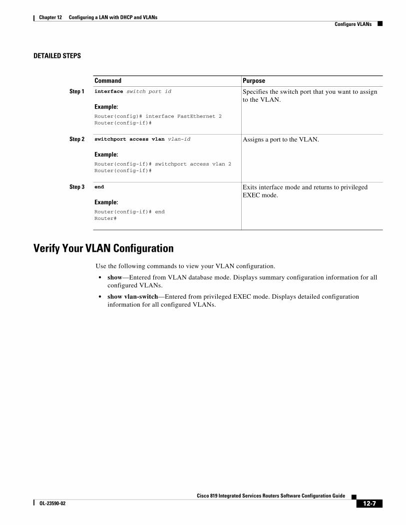
Chapter 12 Configuring a LAN with DHCP and VLANs Configure VLANs
DETAILED STEPS
Verify Your VLAN ConfigurationUse the following commands to view your VLAN configuration.
• show—Entered from VLAN database mode. Displays summary configuration information for all configured VLANs.
• show vlan-switch—Entered from privileged EXEC mode. Displays detailed configuration information for all configured VLANs.
Command Purpose
Step 1 interface switch port id
Example:Router(config)# interface FastEthernet 2Router(config-if)#
Specifies the switch port that you want to assign to the VLAN.
Step 2 switchport access vlan vlan-id
Example:Router(config-if)# switchport access vlan 2Router(config-if)#
Assigns a port to the VLAN.
Step 3 end
Example:Router(config-if)# endRouter#
Exits interface mode and returns to privileged EXEC mode.
12-7Cisco 819 Integrated Services Routers Software Configuration Guide
OL-23590-02

Chapter 12 Configuring a LAN with DHCP and VLANs Configure VLANs
Router# vlan databaseRouter(vlan)# show
VLAN ISL Id: 1 Name: default Media Type: Ethernet VLAN 802.10 Id: 100001 State: Operational MTU: 1500 Translational Bridged VLAN: 1002 Translational Bridged VLAN: 1003
VLAN ISL Id: 2 Name: VLAN0002 Media Type: Ethernet VLAN 802.10 Id: 100002 State: Operational MTU: 1500
VLAN ISL Id: 3 Name: red-vlan Media Type: Ethernet VLAN 802.10 Id: 100003 State: Operational MTU: 1500
VLAN ISL Id: 1002 Name: fddi-default Media Type: FDDI VLAN 802.10 Id: 101002 State: Operational MTU: 1500 Bridge Type: SRB Translational Bridged VLAN: 1 Translational Bridged VLAN: 1003
VLAN ISL Id: 1003 Name: token-ring-default Media Type: Token Ring VLAN 802.10 Id: 101003 State: Operational MTU: 1500 Bridge Type: SRB Ring Number: 0 Bridge Number: 1 Parent VLAN: 1005 Maximum ARE Hop Count: 7 Maximum STE Hop Count: 7 Backup CRF Mode: Disabled Translational Bridged VLAN: 1 Translational Bridged VLAN: 1002
VLAN ISL Id: 1004 Name: fddinet-default Media Type: FDDI Net VLAN 802.10 Id: 101004 State: Operational MTU: 1500 Bridge Type: SRB Bridge Number: 1 STP Type: IBM
VLAN ISL Id: 1005 Name: trnet-default
12-8Cisco 819 Integrated Services Routers Software Configuration Guide
OL-23590-02

Chapter 12 Configuring a LAN with DHCP and VLANs Configure VLANs
Media Type: Token Ring Net VLAN 802.10 Id: 101005 State: Operational MTU: 1500 Bridge Type: SRB Bridge Number: 1 STP Type: IBM
Router# show vlan-switch
VLAN Name Status Ports---- -------------------------------- --------- -------------------------------1 default active Fa0, Fa1, Fa32 VLAN0002 active Fa21002 fddi-default active1003 token-ring-default active1004 fddinet-default active1005 trnet-default active
VLAN Type SAID MTU Parent RingNo BridgeNo Stp BrdgMode Trans1 Trans2---- ----- ---------- ----- ------ ------ -------- ---- -------- ------ ------1 enet 100001 1500 - - - - - 1002 10032 enet 100002 1500 - - - - - 0 01002 fddi 101002 1500 - - - - - 1 10031003 tr 101003 1500 1005 0 - - srb 1 10021004 fdnet 101004 1500 - - 1 ibm - 0 01005 trnet 101005 1500 - - 1 ibm - 0 0
12-9Cisco 819 Integrated Services Routers Software Configuration Guide
OL-23590-02

Chapter 12 Configuring a LAN with DHCP and VLANs Configure VLANs
12-10Cisco 819 Integrated Services Routers Software Configuration Guide
OL-23590-02

Cisco 819 IntegraOL-23590-02
C H A P T E R 13
Configuring a VPN Using Easy VPN and an IPSec TunnelThis chapter provides an overview of the creation of Virtual Private Networks (VPNs) that can be configured on the Cisco 819 Integrated Services Routers (ISRs).
Cisco routers and other broadband devices provide high-performance connections to the Internet, but many applications also require the security of VPN connections that perform a high level of authentication and that encrypt the data between two particular endpoints.
Two types of VPNs are supported—site-to-site and remote access. Site-to-site VPNs are used to connect branch offices to corporate offices, for example. Remote access VPNs are used by remote clients to log in to a corporate network.
The example in this chapter illustrates the configuration of a remote access VPN that uses the Cisco Easy VPN and an IPSec tunnel to configure and secure the connection between the remote client and the corporate network. Figure 13-1 shows a typical deployment scenario.
13-1ted Services Routers Software Configuration Guide

Chapter 13 Configuring a VPN Using Easy VPN and an IPSec Tunnel
Figure 13-1 Remote Access VPN Using IPSec Tunnel
Cisco Easy VPN
The Cisco Easy VPN client feature eliminates much of the tedious configuration work by implementing the Cisco Unity Client protocol. This protocol allows most VPN parameters, such as internal IP addresses, internal subnet masks, DHCP server addresses, WINS server addresses, and split-tunneling flags, to be defined at a VPN server that is acting as an IPSec server.
An Easy VPN server-enabled device can terminate VPN tunnels initiated by mobile and remote workers who are running Cisco Easy VPN Remote software on PCs. Easy VPN server-enabled devices allow remote routers to act as Easy VPN Remote nodes.
The Cisco Easy VPN client feature can be configured in one of two modes—client mode or network extension mode. Client mode is the default configuration and allows only devices at the client site to access resources at the central site. Resources at the client site are unavailable to the central site. Network extension mode allows users at the central site to access network resources on the client site.
After the IPSec server has been configured, a VPN connection can be created with minimal configuration on an IPSec client, such as a supported Cisco 819 ISR. When the IPSec client initiates the VPN tunnel connection, the IPSec server pushes the IPSec policies to the IPSec client and creates the corresponding VPN tunnel connection.
1 Remote, networked users
2 VPN client—Cisco 819 ISRs
3 Router—Providing the corporate office network access
4 VPN server—Easy VPN server
5 Corporate office with a network address of 10.1.1.1
6 IPSec tunnel
2
1
1217
82
Internet
3 4
5
6
13-2Cisco 819 Integrated Services Routers Software Configuration Guide
OL-23590-02

Chapter 13 Configuring a VPN Using Easy VPN and an IPSec Tunnel Configure the IKE Policy
Note The Cisco Easy VPN client feature supports configuration of only one destination peer. If your application requires the creation of multiple VPN tunnels, you must manually configure the IPSec VPN and Network Address Translation/Peer Address Translation (NAT/PAT) parameters on both the client and the server.
Configuration Tasks
Perform the following tasks to configure your router for this network scenario:
• Configure the IKE Policy, page 13-3
• Configure Group Policy Information, page 13-5
• Apply Mode Configuration to the Crypto Map, page 13-6
• Enable Policy Lookup, page 13-7
• Configure IPSec Transforms and Protocols, page 13-8
• Configure the IPSec Crypto Method and Parameters, page 13-8
• Apply the Crypto Map to the Physical Interface, page 13-10
• Create an Easy VPN Remote Configuration, page 13-10
An example showing the results of these configuration tasks is provided in the “Configuration Example” section on page 13-12.
Note The procedures in this chapter assume that you have already configured basic router features, as well as PPPoE or PPPoA with NAT, DCHP and VLANs. If you have not performed these configurations tasks, see “Basic Router Configuration” section on page 5-1.
Note The examples shown in this chapter refer only to the endpoint configuration on the Cisco 819 router. Any VPN connection requires both endpoints be configured properly to function. See the software configuration documentation as needed to configure VPN for other router models.
Configure the IKE PolicyPerform these steps to configure the Internet Key Exchange (IKE) policy, beginning in global configuration mode:
SUMMARY STEPS
1. crypto isakmp policy priority
2. encryption {des | 3des | aes | aes 192 | aes 256}
3. hash {md5 | sha}
4. authentication {rsa-sig | rsa-encr | pre-share}
5. group {1 | 2 | 5}
6. lifetime seconds
7. exit
13-3Cisco 819 Integrated Services Routers Software Configuration Guide
OL-23590-02
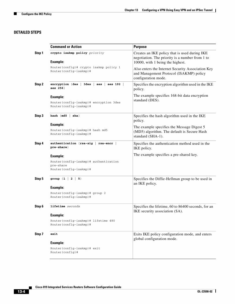
Chapter 13 Configuring a VPN Using Easy VPN and an IPSec Tunnel Configure the IKE Policy
DETAILED STEPS
Command or Action Purpose
Step 1 crypto isakmp policy priority
Example:Router(config)# crypto isakmp policy 1Router(config-isakmp)#
Creates an IKE policy that is used during IKE negotiation. The priority is a number from 1 to 10000, with 1 being the highest.
Also enters the Internet Security Association Key and Management Protocol (ISAKMP) policy configuration mode.
Step 2 encryption {des | 3des | aes | aes 192 | aes 256}
Example:Router(config-isakmp)# encryption 3desRouter(config-isakmp)#
Specifies the encryption algorithm used in the IKE policy.
The example specifies 168-bit data encryption standard (DES).
Step 3 hash {md5 | sha}
Example:Router(config-isakmp)# hash md5Router(config-isakmp)#
Specifies the hash algorithm used in the IKE policy.
The example specifies the Message Digest 5 (MD5) algorithm. The default is Secure Hash standard (SHA-1).
Step 4 authentication {rsa-sig | rsa-encr | pre-share}
Example:Router(config-isakmp)# authentication pre-shareRouter(config-isakmp)#
Specifies the authentication method used in the IKE policy.
The example specifies a pre-shared key.
Step 5 group {1 | 2 | 5}
Example:Router(config-isakmp)# group 2Router(config-isakmp)#
Specifies the Diffie-Hellman group to be used in an IKE policy.
Step 6 lifetime seconds
Example:Router(config-isakmp)# lifetime 480Router(config-isakmp)#
Specifies the lifetime, 60 to 86400 seconds, for an IKE security association (SA).
Step 7 exit
Example:Router(config-isakmp)# exitRouter(config)#
Exits IKE policy configuration mode, and enters global configuration mode.
13-4Cisco 819 Integrated Services Routers Software Configuration Guide
OL-23590-02

Chapter 13 Configuring a VPN Using Easy VPN and an IPSec Tunnel Configure Group Policy Information
Configure Group Policy InformationPerform these steps to configure the group policy, beginning in global configuration mode:
SUMMARY STEPS
1. crypto isakmp client configuration group {group-name | default}
2. key name
3. dns primary-server
4. domain name
5. exit
6. ip local pool {default | poolname} [low-ip-address [high-ip-address]]
DETAILED STEPS
Command or Action Purpose
Step 1 crypto isakmp client configuration group {group-name | default}
Example:Router(config)# crypto isakmp client configuration group rtr-remoteRouter(config-isakmp-group)#
Creates an IKE policy group containing attributes to be downloaded to the remote client.
Also enters the Internet Security Association Key and Management Protocol (ISAKMP) group policy configuration mode.
Step 2 key name
Example:Router(config-isakmp-group)# key secret-passwordRouter(config-isakmp-group)#
Specifies the IKE pre-shared key for the group policy.
Step 3 dns primary-server
Example:Router(config-isakmp-group)# dns 10.50.10.1Router(config-isakmp-group)#
Specifies the primary Domain Name System (DNS) server for the group.
Note You may also want to specify Windows Internet Naming Service (WINS) servers for the group by using the wins command.
Step 4 domain name
Example:Router(config-isakmp-group)# domain company.comRouter(config-isakmp-group)#
Specifies group domain membership.
13-5Cisco 819 Integrated Services Routers Software Configuration Guide
OL-23590-02

Chapter 13 Configuring a VPN Using Easy VPN and an IPSec Tunnel Apply Mode Configuration to the Crypto Map
Apply Mode Configuration to the Crypto MapPerform these steps to apply mode configuration to the crypto map, beginning in global configuration mode:
SUMMARY STEPS
1. crypto map map-name isakmp authorization list list-name
2. crypto map tag client configuration address [initiate | respond]
DETAILED STEPS
Step 5 exit
Example:Router(config-isakmp-group)# exitRouter(config)#
Exits IKE group policy configuration mode, and enters global configuration mode.
Step 6 ip local pool {default | poolname} [low-ip-address [high-ip-address]]
Example:Router(config)# ip local pool dynpool 30.30.30.20 30.30.30.30Router(config)#
Specifies a local address pool for the group.
For details about this command and additional parameters that can be set, see Cisco IOS Dial Technologies Command Reference.
Command or Action Purpose
Command or Action Purpose
Step 1 crypto map map-name isakmp authorization list list-name
Example:Router(config)# crypto map dynmap isakmp authorization list rtr-remoteRouter(config)#
Applies mode configuration to the crypto map and enables key lookup (IKE queries) for the group policy from an authentication, authorization, and accounting (AAA) server.
Step 2 crypto map tag client configuration address [initiate | respond]
Example:Router(config)# crypto map dynmap client configuration address respondRouter(config)#
Configures the router to reply to mode configuration requests from remote clients.
13-6Cisco 819 Integrated Services Routers Software Configuration Guide
OL-23590-02
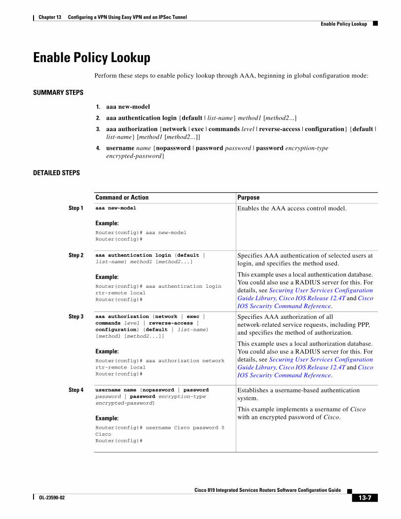
Chapter 13 Configuring a VPN Using Easy VPN and an IPSec Tunnel Enable Policy Lookup
Enable Policy LookupPerform these steps to enable policy lookup through AAA, beginning in global configuration mode:
SUMMARY STEPS
1. aaa new-model
2. aaa authentication login {default | list-name} method1 [method2...]
3. aaa authorization {network | exec | commands level | reverse-access | configuration} {default | list-name} [method1 [method2...]]
4. username name {nopassword | password password | password encryption-type encrypted-password}
DETAILED STEPS
Command or Action Purpose
Step 1 aaa new-model
Example:Router(config)# aaa new-modelRouter(config)#
Enables the AAA access control model.
Step 2 aaa authentication login {default | list-name} method1 [method2...]
Example:Router(config)# aaa authentication login rtr-remote localRouter(config)#
Specifies AAA authentication of selected users at login, and specifies the method used.
This example uses a local authentication database. You could also use a RADIUS server for this. For details, see Securing User Services Configuration Guide Library, Cisco IOS Release 12.4T and Cisco IOS Security Command Reference.
Step 3 aaa authorization {network | exec | commands level | reverse-access | configuration} {default | list-name} [method1 [method2...]]
Example:Router(config)# aaa authorization network rtr-remote localRouter(config)#
Specifies AAA authorization of all network-related service requests, including PPP, and specifies the method of authorization.
This example uses a local authorization database. You could also use a RADIUS server for this. For details, see Securing User Services Configuration Guide Library, Cisco IOS Release 12.4T and Cisco IOS Security Command Reference.
Step 4 username name {nopassword | password password | password encryption-type encrypted-password}
Example:Router(config)# username Cisco password 0 CiscoRouter(config)#
Establishes a username-based authentication system.
This example implements a username of Cisco with an encrypted password of Cisco.
13-7Cisco 819 Integrated Services Routers Software Configuration Guide
OL-23590-02

Chapter 13 Configuring a VPN Using Easy VPN and an IPSec Tunnel Configure IPSec Transforms and Protocols
Configure IPSec Transforms and ProtocolsA transform set represents a certain combination of security protocols and algorithms. During IKE negotiation, the peers agree to use a particular transform set for protecting data flow.
During IKE negotiations, the peers search in multiple transform sets for a transform that is the same at both peers. When such a transform set is found, it is selected and applied to the protected traffic as a part of both peers’ configurations.
Perform these steps to specify the IPSec transform set and protocols, beginning in global configuration mode:
SUMMARY STEPS
1. crypto ipsec transform-set transform-set-name transform1 [transform2] [transform3] [transform4]
2. crypto ipsec security-association lifetime {seconds seconds | kilobytes kilobytes}
DETAILED STEPS
Note With manually established security associations, there is no negotiation with the peer, and both sides must specify the same transform set.
Configure the IPSec Crypto Method and ParametersA dynamic crypto map policy processes negotiation requests for new security associations from remote IPSec peers, even if the router does not know all the crypto map parameters (for example, IP address).
Perform these steps to configure the IPSec crypto method, beginning in global configuration mode:
Command or Action Purpose
Step 1 crypto ipsec transform-set transform-set-name transform1 [transform2] [transform3] [transform4]
Example:Router(config)# crypto ipsec transform-set vpn1 esp-3des esp-sha-hmacRouter(config)#
Defines a transform set—an acceptable combination of IPSec security protocols and algorithms.
See Cisco IOS Security Command Reference for details about the valid transforms and combinations.
Step 2 crypto ipsec security-association lifetime {seconds seconds | kilobytes kilobytes}
Example:Router(config)# crypto ipsec security-association lifetime seconds 86400Router(config)#
Specifies global lifetime values used when IPSec security associations are negotiated.
See Cisco IOS Security Command Reference for details.
13-8Cisco 819 Integrated Services Routers Software Configuration Guide
OL-23590-02

Chapter 13 Configuring a VPN Using Easy VPN and an IPSec Tunnel Configure the IPSec Crypto Method and Parameters
SUMMARY STEPS
1. crypto dynamic-map dynamic-map-name dynamic-seq-num
2. set transform-set transform-set-name [transform-set-name2...transform-set-name6]
3. reverse-route
4. exit
5. crypto map map-name seq-num [ipsec-isakmp] [dynamic dynamic-map-name] [discover] [profile profile-name]
DETAILED STEPS
Command or Action Purpose
Step 1 crypto dynamic-map dynamic-map-name dynamic-seq-num
Example:Router(config)# crypto dynamic-map dynmap 1Router(config-crypto-map)#
Creates a dynamic crypto map entry and enters crypto map configuration mode.
See Cisco IOS Security Command Reference for more details about this command.
Step 2 set transform-set transform-set-name [transform-set-name2...transform-set-name6]
Example:Router(config-crypto-map)# set transform-set vpn1Router(config-crypto-map)#
Specifies which transform sets can be used with the crypto map entry.
Step 3 reverse-route
Example:Router(config-crypto-map)# reverse-routeRouter(config-crypto-map)#
Creates source proxy information for the crypto map entry.
See Cisco IOS Security Command Reference for details.
Step 4 exit
Example:Router(config-crypto-map)# exitRouter(config)#
Returns to global configuration mode.
Step 5 crypto map map-name seq-num [ipsec-isakmp] [dynamic dynamic-map-name] [discover] [profile profile-name]
Example:Router(config)# crypto map static-map 1 ipsec-isakmp dynamic dynmapRouter(config)#
Creates a crypto map profile.
13-9Cisco 819 Integrated Services Routers Software Configuration Guide
OL-23590-02

Chapter 13 Configuring a VPN Using Easy VPN and an IPSec Tunnel Apply the Crypto Map to the Physical Interface
Apply the Crypto Map to the Physical InterfaceThe crypto maps must be applied to each interface through which IP Security (IPSec) traffic flows. Applying the crypto map to the physical interface instructs the router to evaluate all the traffic against the security associations database. With the default configurations, the router provides secure connectivity by encrypting the traffic sent between remote sites. However, the public interface still allows the rest of the traffic to pass and provides connectivity to the Internet.
Perform these steps to apply a crypto map to an interface, beginning in global configuration mode:
SUMMARY STEPS
1. interface type number
2. crypto map map-name
3. exit
DETAILED STEPS
Create an Easy VPN Remote Configuration The router acting as the IPSec remote router must create an Easy VPN remote configuration and assign it to the outgoing interface.
Perform these steps to create the remote configuration, beginning in global configuration mode:
SUMMARY STEPS
1. crypto ipsec client ezvpn name
2. group group-name key group-key
Command or Action Purpose
Step 1 interface type number
Example:Router(config)# interface fastethernet 4Router(config-if)#
Enters the interface configuration mode for the interface to which you want the crypto map applied.
Step 2 crypto map map-name
Example:Router(config-if)# crypto map static-mapRouter(config-if)#
Applies the crypto map to the interface.
See Cisco IOS Security Command Reference for more details about this command.
Step 3 exit
Example:Router(config-crypto-map)# exitRouter(config)#
Returns to global configuration mode.
13-10Cisco 819 Integrated Services Routers Software Configuration Guide
OL-23590-02

Chapter 13 Configuring a VPN Using Easy VPN and an IPSec Tunnel Create an Easy VPN Remote Configuration
3. peer {ipaddress | hostname}
4. mode {client | network-extension | network extension plus}
5. exit
6. interface type number
7. crypto ipsec client ezvpn name [outside | inside]
8. exit
DETAILED STEPS
Command or Action Purpose
Step 1 crypto ipsec client ezvpn name
Example:Router(config)# crypto ipsec client ezvpn ezvpnclientRouter(config-crypto-ezvpn)#
Creates a Cisco Easy VPN remote configuration, and enters Cisco Easy VPN remote configuration mode.
Step 2 group group-name key group-key
Example:Router(config-crypto-ezvpn)# group ezvpnclient key secret-passwordRouter(config-crypto-ezvpn)#
Specifies the IPSec group and IPSec key value for the VPN connection.
Step 3 peer {ipaddress | hostname}
Example:Router(config-crypto-ezvpn)# peer 192.168.100.1Router(config-crypto-ezvpn)#
Specifies the peer IP address or hostname for the VPN connection.
Note A hostname can be specified only when the router has a DNS server available for hostname resolution.
Step 4 mode {client | network-extension | network extension plus}
Example:Router(config-crypto-ezvpn)# mode clientRouter(config-crypto-ezvpn)#
Specifies the VPN mode of operation.
Step 5 exit
Example:Router(config-crypto-ezvpn)# exitRouter(config)#
Returns to global configuration mode.
Step 6 interface type number
Example:Router(config)# interface fastethernet 4Router(config-if)#
Enters the interface configuration mode for the interface to which you want the Cisco Easy VPN remote configuration applied.
Note For routers with an ATM WAN interface, this command would be interface atm 0.
13-11Cisco 819 Integrated Services Routers Software Configuration Guide
OL-23590-02

Chapter 13 Configuring a VPN Using Easy VPN and an IPSec Tunnel Verifying Your Easy VPN Configuration
Verifying Your Easy VPN ConfigurationThe following example verifies your easy vpn connection:
Router# show crypto ipsec client ezvpn
Tunnel name :ezvpnclientInside interface list:vlan 1Outside interface:fastethernet 4Current State:IPSEC_ACTIVELast Event:SOCKET_UPAddress:8.0.0.5Mask:255.255.255.255Default Domain:cisco.com
Configuration ExampleThe following configuration example shows a portion of the configuration file for the VPN and IPSec tunnel described in this chapter:
!aaa new-model!aaa authentication login rtr-remote localaaa authorization network rtr-remote localaaa session-id common!username Cisco password 0 Cisco!crypto isakmp policy 1
encryption 3desauthentication pre-sharegroup 2lifetime 480
!crypto isakmp client configuration group rtr-remote
key secret-passworddns 10.50.10.1 10.60.10.1domain company.com
Step 7 crypto ipsec client ezvpn name [outside | inside]
Example:Router(config-if)# crypto ipsec client ezvpn ezvpnclient outsideRouter(config-if)#
Assigns the Cisco Easy VPN remote configuration to the WAN interface, causing the router to automatically create the NAT or port address translation (PAT) and access list configuration needed for the VPN connection.
Step 8 exit
Example:Router(config-crypto-ezvpn)# exitRouter(config)#
Returns to global configuration mode.
Command or Action Purpose
13-12Cisco 819 Integrated Services Routers Software Configuration Guide
OL-23590-02

Chapter 13 Configuring a VPN Using Easy VPN and an IPSec Tunnel Configuration Example
pool dynpool!crypto ipsec transform-set vpn1 esp-3des esp-sha-hmac!crypto ipsec security-association lifetime seconds 86400!crypto dynamic-map dynmap 1
set transform-set vpn1reverse-route
!crypto map static-map 1 ipsec-isakmp dynamic dynmapcrypto map dynmap isakmp authorization list rtr-remotecrypto map dynmap client configuration address respond
crypto ipsec client ezvpn ezvpnclientconnect autogroup 2 key secret-passwordmode clientpeer 192.168.100.1
!
interface fastethernet 4crypto ipsec client ezvpn ezvpnclient outsidecrypto map static-map
!interface vlan 1
crypto ipsec client ezvpn ezvpnclient inside!
13-13Cisco 819 Integrated Services Routers Software Configuration Guide
OL-23590-02

Chapter 13 Configuring a VPN Using Easy VPN and an IPSec Tunnel Configuration Example
13-14Cisco 819 Integrated Services Routers Software Configuration Guide
OL-23590-02

Cisco 819 Integrated SeOL-18906-02
A
P P E N D I X A Cisco IOS Software Basic SkillsUnderstanding how to use Cisco IOS software can save you time when you are configuring your router. This appendix contains the following sections which provide basic information:
• Configuring the Router from a PC, page A-1
• Understanding Command Modes, page A-2
• Getting Help, page A-4
• Enable Secret Passwords and Enable Passwords, page A-5
• Entering Global Configuration Mode, page A-5
• Using Commands, page A-6
• Saving Configuration Changes, page A-7
• Summary, page A-7
• Where to Go Next, page A-7
If you are already familiar with Cisco IOS software, go to the following chapter:
• Basic Router Configuration, page 5-1
Configuring the Router from a PCYou can configure your router from a PC that is connected through the console port by using terminal emulation software. The PC uses this software to send commands to your router. Table A-1 lists some common types of terminal emulation software that you can use, depending on the operating system that you are running.
A-1rvices Routers Software Configuration Guide

Appendix A Cisco IOS Software Basic Skills Understanding Command Modes
You can use the terminal emulation software to change settings for the router that is connected to the PC. Configure the software to the following standard VT-100 emulation settings so that your PC can communicate with your router:
• 9600 baud
• 8 data bits
• No parity
• 1 stop bit
• No flow control
These settings should match the default settings of your router. To change the router baud, data bits, parity, or stop bits settings, you must reconfigure parameters in the ROM monitor. For more information, see the “ROM Monitor” section on page C-1 To change the router flow control setting, use the flowcontrol command in global configuration mode.
For information on how to enter global configuration mode so that you can configure your router, see the “Entering Global Configuration Mode” section on page A-5.
Understanding Command ModesThis section describes the Cisco IOS command mode structure. Each command mode supports specific Cisco IOS commands. For example, you can use the interface type number command only from global configuration mode.
The following Cisco IOS command modes are hierarchical. When you begin a router session, you are in user EXEC mode.
• User EXEC
• Privileged EXEC
• Global configuration
Table A-2 lists the command modes that are used in this guide, describes how to access each mode, shows the prompt for each mode, and explains how to exit to a mode or enter another mode. Because each mode configures different router elements, you might need to enter and exit modes frequently. You can see a list of available commands for a particular mode by entering a question mark (?) at the prompt. For a description of each command, including syntax, see the Cisco IOS Release 12.3 documentation set.
Table A-1 Types of Terminal Emulation Software
PC Operating System Terminal Emulation Software
Windows 95, Windows 98, Windows 2000, Windows NT, Windows XP
HyperTerm (included with Windows software), ProComm Plus
Windows 3.1 Terminal (included with Windows software)
Macintosh ProComm, VersaTerm
A-2Cisco 819 Integrated Services Routers Software Configuration Guide
OL-18906-02

Appendix A Cisco IOS Software Basic Skills Understanding Command Modes
Table A-2 Command Modes Summary
Mode Access Method Prompt Mode Exit and Entrance About This Mode
User EXEC Begin a session with your router.
Router> To exit a router session, enter the logout command.
Use this mode to:
• Change terminal settings.
• Perform basic tests.
• Display system information.
Privileged EXEC
Enter the enable command from user EXEC mode.
Router# • To exit to user EXEC mode, enter the disable command.
• To enter global configuration mode, enter the configure command.
Use this mode to:
• Configure your router operating parameters.
• Perform the verification steps shown in this guide.
To prevent unauthorized changes to your router configuration, protect access to this mode by using a password as described in the “Enable Secret Passwords and Enable Passwords” procedure on page A-5.
Global configuration
Enter the configure command from privileged EXEC mode.
Router (config)#
• To exit to privileged EXEC mode, enter the exit or end command or press Ctrl-Z.
• To enter interface configuration mode, enter the interface command.
Use this mode to configure parameters that apply to your router globally.
From this mode, you can access the following modes:
• Interface configuration
• Router configuration
• Line configuration
Interface configuration
Enter the interface command (with a specific interface, such as interface atm 0) from global configuration mode.
Router (config-if)#
• To exit to global configuration mode, enter the exit command.
• To exit to privileged EXEC mode, enter the end command or press Ctrl-Z.
• To enter subinterface configuration mode, specify a subinterface by using the interface command.
Use this mode to configure parameters for the router Ethernet and serial interfaces or subinterfaces.
A-3Cisco 819 Integrated Services Routers Software Configuration Guide
OL-18906-02

Appendix A Cisco IOS Software Basic Skills Getting Help
Getting HelpYou can use the question mark (?) and arrow keys to help you enter commands.
For a list of available commands for a prticular command mode, enter a question mark:
Router> ?access-enable Create a temporary access-list entryaccess-profile Apply user-profile to interfaceclear Reset functions...
To complete a command, enter a few known characters followed by a question mark (with no space):
Router> sh?* s=show set show slip systat
For a list of command variables, enter the command followed by a space and a question mark:
Router> show ?...clock Display the system clockdialer Dialer parameters and statisticsexception exception information...
To redisplay a command that you previously entered, press the Up Arrow key. You can continue to press the Up Arrow key for more commands.
Router configuration
Enter one of the router commands followed by the appropriate keyword—for example router rip—from global configuration mode.
Router (config- router)#
• To exit to global configuration mode, enter the exit command.
• To exit to privileged EXEC mode, enter the end command or press Ctrl-Z.
Use this mode to configure an IP routing protocol.
Line configuration
Enter the line command with the desired line number and optional line type, for example, line 0, from global configuration mode.
Router (config- line)#
• To exit to global configuration mode, enter the exit command.
• To exit to privileged EXEC mode, enter the end command or press Ctrl-Z.
Use this mode to configure parameters for the terminal line.
Table A-2 Command Modes Summary (continued)
Mode Access Method Prompt Mode Exit and Entrance About This Mode
A-4Cisco 819 Integrated Services Routers Software Configuration Guide
OL-18906-02

Appendix A Cisco IOS Software Basic Skills Enable Secret Passwords and Enable Passwords
Enable Secret Passwords and Enable PasswordsBy default, the router ships without password protection. Because many privileged EXEC commands are used to set operating parameters, you should password-protect these commands to prevent unauthorized use.
You can use two commands to do this:
• enable secret password—A very secure, encrypted password.
• enable password—A less secure, unencrypted local password.
Both the enable and enable secret passwords control access to various privilege levels (0 to 15). The enable password is intended for local use and is thus unencrypted. The enable secret password is intended for network use; that is, in environments where the password crosses the network or is stored on a TFTP server. You must enter an enable secret or enable password with a privilege level of 1 to gain access to privileged EXEC mode commands.
For maximum security, the passwords should be different. If you enter the same password for both during the setup process, your router accepts the passwords, but warns you that they should be different.
An enable secret password can contain from 1 to 25 uppercase and lowercase alphanumeric characters. An enable password can contain any number of uppercase and lowercase alphanumeric characters. In both cases, a number cannot be the first character. Spaces are also valid password characters; for example, two words is a valid password. Leading spaces are ignored; trailing spaces are recognized.
Entering Global Configuration ModeTo make any configuration changes to your router, you must be in global configuration mode. This section describes how to enter global configuration mode while using a terminal or PC that is connected to your router console port.
To enter global configuration mode, follow these steps:
Step 1 After your router boots up, enter the enable or enable secret command:
Router> enable
Step 2 If you have configured your router with an enable password, enter it when you are prompted.
The enable password does not appear on the screen when you enter it. This example shows how to enter privileged EXEC mode:
Password: enable_passwordRouter#
Privileged EXEC mode is indicated by the pound sign (#) in the prompt. You can now make changes to your router configuration.
Step 3 Enter the configure terminal command to enter global configuration mode:
Router# configure terminalRouter(config)#
You can now make changes to your router configuration.
A-5Cisco 819 Integrated Services Routers Software Configuration Guide
OL-18906-02
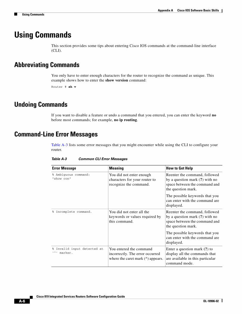
Appendix A Cisco IOS Software Basic Skills Using Commands
Using CommandsThis section provides some tips about entering Cisco IOS commands at the command-line interface (CLI).
Abbreviating CommandsYou only have to enter enough characters for the router to recognize the command as unique. This example shows how to enter the show version command:
Router # sh v
Undoing CommandsIf you want to disable a feature or undo a command that you entered, you can enter the keyword no before most commands; for example, no ip routing.
Command-Line Error MessagesTable A-3 lists some error messages that you might encounter while using the CLI to configure your router.
Table A-3 Common CLI Error Messages
Error Message Meaning How to Get Help
% Ambiguous command: "show con"
You did not enter enough characters for your router to recognize the command.
Reenter the command, followed by a question mark (?) with no space between the command and the question mark.
The possible keywords that you can enter with the command are displayed.
% Incomplete command. You did not enter all the keywords or values required by this command.
Reenter the command, followed by a question mark (?) with no space between the command and the question mark.
The possible keywords that you can enter with the command are displayed.
% Invalid input detected at ‘^’ marker.
You entered the command incorrectly. The error occurred where the caret mark (^) appears.
Enter a question mark (?) to display all the commands that are available in this particular command mode.
A-6Cisco 819 Integrated Services Routers Software Configuration Guide
OL-18906-02

Appendix A Cisco IOS Software Basic Skills Saving Configuration Changes
Saving Configuration ChangesYou must enter the copy running-config startup-config command to save your configuration changes to NVRAM so that they are not lost if there is a system reload or power outage. This example shows how to use this command to save your changes:
Router# copy running-config startup-configDestination filename [startup-config]?
Press Return to accept the default destination filename startup-config, or enter your desired destination filename and press Return.
It might take a minute or two to save the configuration to NVRAM. After the configuration has been saved, the following message appears:
Building configuration...Router#
SummaryNow that you have reviewed some Cisco IOS software basics, you can begin to configure your router. Remember:
• You can use the question mark (?) and arrow keys to help you enter commands.
• Each command mode restricts you to a set of commands. If you are having difficulty entering a command, check the prompt, and then enter the question mark (?) for a list of available commands. You might be in the wrong command mode or using the wrong syntax.
• To disable a feature, enter the keyword no before the command; for example, no ip routing.
• Save your configuration changes to NVRAM so that they are not lost if there is a system reload or power outage.
Where to Go NextTo configure your router, go to the “Basic Router Configuration” section on page 5-1.
A-7Cisco 819 Integrated Services Routers Software Configuration Guide
OL-18906-02

Appendix A Cisco IOS Software Basic Skills Where to Go Next
A-8Cisco 819 Integrated Services Routers Software Configuration Guide
OL-18906-02
Cisco 860 Series, Cisco 880 Series, and Cisco 890 Series Integrated SeOL-18906-02
A
P P E N D I X B ConceptsThis appendix contains conceptual information that may be useful to Internet service providers or network administrators when they configure Cisco routers.
The following topics are included in this appendix:
• Network Protocols, page B-1
• Routing Protocol Options, page B-2
• PPP Authentication Protocols, page B-3
• TACACS+, page B-4
• Ethernet, page B-4
• Dial Backup, page B-5
• NAT, page B-6
• Easy IP (Phase 1), page B-6
• Easy IP (Phase 2), page B-7
• QoS, page B-7
• Access Lists, page B-9
Network ProtocolsNetwork protocols enable the network to pass data from its source to a specific destination over LAN or WAN links. Routing address tables are included in the network protocols to provide the best path for moving the data through the network.
IPThe best-known Transmission Control Protocol/Internet Protocol (TCP/IP) at the internetwork layer is IP, which provides the basic packet delivery service for all TCP/IP networks. In addition to the physical node addresses, the IP protocol implements a system of logical host addresses called IP addresses. The IP addresses are used by the internetwork and higher layers to identify devices and to perform internetwork routing. The Address Resolution Protocol (ARP) enables IP to identify the physical address that matches a given IP address.
IP is used by all protocols in the layers above and below it to deliver data, which means that all TCP/IP data flows through IP when it is sent and received regardless of its final destination.
B-1rvices Routers Software Configuration Guide

Appendix B Concepts Routing Protocol Options
IP is a connectionless protocol, which means that IP does not exchange control information (called a handshake) to establish an end-to-end connection before transmitting data. In contrast, a connection-oriented protocol exchanges control information with the remote computer to verify that it is ready to receive data before sending it. When the handshaking is successful, the computers have established a connection. IP relies on protocols in other layers to establish the connection if connection-oriented services are required.
Internet Packet Exchange (IPX) exchanges routing information using Routing Information Protocol (RIP), a dynamic distance-vector routing protocol. RIP is described in more detail in the following sections.
Routing Protocol OptionsRouting protocols include the following:
• Routing Information Protocol (RIP)
• Enhanced Interior Gateway Routing Protocol (Enhanced IGRP)
RIP and Enhanced IGRP differ in several ways, as shown in Table B-1.
RIPRIP is an associated protocol for IP, and is widely used for routing protocol traffic over the Internet. RIP is a distance-vector routing protocol, which means that it uses distance (hop count) as its metric for route selection. Hop count is the number of routers that a packet must traverse to reach its destination. For example, if a particular route has a hop count of 2, then a packet must traverse two routers to reach its destination.
By default, RIP routing updates are broadcast every 30 seconds. You can reconfigure the interval at which the routing updates are broadcast. You can also configure triggered extensions to RIP so that routing updates are sent only when the routing database is updated. For more information on triggered extensions to RIP, see the Cisco IOS Release 12.3 documentation set.
Table B-1 RIP and Enhanced IGRP Comparison
Protocol Ideal Topology Metric Routing Updates
RIP Suited for topologies with 15 or fewer hops.
Hop count. Maximum hop count is 15. Best route is one with lowest hop count.
By default, every 30 seconds. You can reconfigure this value and also use triggered extensions to RIP.
Enhanced IGRP
Suited for large topologies with 16 or more hops to reach a destination.
Distance information. Based on a successor, which is a neighboring router that has a least-cost path to a destination that is guaranteed to not be part of a routing loop.
Hello packets sent every 5 seconds, as well as incremental updates sent when the state of a destination changes.
B-2Cisco 860 Series, Cisco 880 Series, and Cisco 890 Series Integrated Services Routers Software Configuration Guide
OL-18906-02

Appendix B Concepts PPP Authentication Protocols
Enhanced IGRPEnhanced IGRP is an advanced Cisco-proprietary distance-vector and link-state routing protocol, which means it uses a metric more sophisticated than distance (hop count) for route selection. Enhanced IGRP uses a metric based on a successor, which is a neighboring router that has a least-cost path to a destination that is guaranteed not to be part of a routing loop. If a successor for a particular destination does not exist but neighbors advertise the destination, the router must recompute a route.
Each router that is running Enhanced IGRP sends hello packets every 5 seconds to inform neighboring routers that it is functioning. If a particular router does not send a hello packet within a prescribed period, Enhanced IGRP assumes that the state of a destination has changed and sends an incremental update.
Because Enhanced IGRP supports IP, you can use one routing protocol for multiprotocol network environments, minimizing the size of the routing tables and the amount of routing information.
PPP Authentication ProtocolsThe Point-to-Point Protocol (PPP) encapsulates network-layer protocol information over point-to-point links.
PPP originated as an encapsulation protocol for transporting IP traffic over point-to-point links. PPP also established a standard for the assignment and management of IP addresses, asynchronous (start/stop) and bit-oriented synchronous encapsulation, network protocol multiplexing, link configuration, link quality testing, error detection, and option negotiation for such capabilities as network-layer address negotiation and data-compression negotiation. PPP supports these functions by providing an extensible Link Control Protocol (LCP) and a family of Network Control Protocols (NCPs) to negotiate optional configuration parameters and facilities.
The current implementation of PPP supports two security authentication protocols to authenticate a PPP session:
• Password Authentication Protocol (PAP)
• Challenge Handshake Authentication Protocol (CHAP)
PPP with PAP or CHAP authentication is often used to inform the central site which remote routers are connected to it.
PAPPAP uses a two-way handshake to verify the passwords between routers. To understand how PAP works, imagine a network topology in which a remote office Cisco router is connected to a corporate office Cisco router. After the PPP link is established, the remote office router repeatedly sends a configured username and password until the corporate office router accepts the authentication.
PAP has the following characteristics:
• The password portion of the authentication is sent across the link in clear text (not scrambled or encrypted).
• PAP provides no protection from playback or repeated trial-and-error attacks.
• The remote office router controls the frequency and timing of the authentication attempts.
B-3Cisco 860 Series, Cisco 880 Series, and Cisco 890 Series Integrated Services Routers Software Configuration Guide
OL-18906-02
Appendix B Concepts TACACS+
CHAPCHAP uses a three-way handshake to verify passwords. To understand how CHAP works, imagine a network topology in which a remote office Cisco router is connected to a corporate office Cisco router.
After the PPP link is established, the corporate office router sends a challenge message to the remote office router. The remote office router responds with a variable value. The corporate office router checks the response against its own calculation of the value. If the values match, the corporate office router accepts the authentication. The authentication process can be repeated anytime after the link is established.
CHAP has the following characteristics:
• The authentication process uses a variable challenge value rather than a password.
• CHAP protects against playback attack through the use of the variable challenge value, which is unique and unpredictable. Repeated challenges limit the time of exposure to any single attack.
• The corporate office router controls the frequency and timing of the authentication attempts.
Note We recommend using CHAP because it is the more secure of the two protocols.
TACACS+Cisco 819 routers support the Terminal Access Controller Access Control System Plus (TACACS+) protocol through Telnet. TACACS+ is a Cisco-proprietary authentication protocol that provides remote access authentication and related network security services, such as event logging. User passwords are administered in a central database rather than in individual routers. TACACS+ also provides support for separate modular authentication, authorization, and accounting (AAA) facilities that are configured at individual routers.
Ethernet Ethernet is a baseband LAN protocol that transports data and voice packets to the WAN interface using carrier sense multiple access collision detect (CSMA/CD). The term is now often used to refer to all CSMA/CD LANs. Ethernet was designed to serve in networks with sporadic, occasionally heavy traffic requirements. The IEEE 802.3 specification was developed in 1980, based on the original Ethernet technology.
Under the Ethernet CSMA/CD media-access process, any host on a CSMA/CD LAN can access the network at any time. Before sending data, CSMA/CD hosts listen for traffic on the network. A host wanting to send data waits until it detects no traffic before it transmits. Ethernet allows any host on the network to transmit whenever the network is quiet. A collision occurs when two hosts listen for traffic, hear none, and then transmit simultaneously. In this situation, both transmissions are damaged, and the hosts must retransmit at some later time. Algorithms determine when the colliding hosts should retransmit.
B-4Cisco 860 Series, Cisco 880 Series, and Cisco 890 Series Integrated Services Routers Software Configuration Guide
OL-18906-02

Appendix B Concepts Dial Backup
Dial BackupDial backup provides protection against WAN downtime by allowing a user to configure a backup modem line connection. The following can be used to bring up the dial backup feature in Cisco IOS software:
• Backup Interface, page B-5
• Floating Static Routes, page B-5
• Dialer Watch, page B-5
Backup InterfaceA backup interface is an interface that stays idle until certain circumstances occur, such as WAN downtime, at which point it is activated. The backup interface can be a physical interface such as a Basic Rate Interface (BRI), or an assigned backup dialer interface to be used in a dialer pool. While the primary line is up, the backup interface is placed in standby mode. In standby mode, the backup interface is effectively shut down until it is enabled. Any route associated with the backup interface does not appear in the routing table.
Because the backup interface command is dependent on the router’s identifying that an interface is physically down, it is commonly used to back up ISDN BRI connections, asynchronous lines, and leased lines. The interfaces to such connections go down when the primary line fails, and the backup interface quickly identifies such failures.
Floating Static RoutesFloating static routes are static routes that have an administrative distance greater than the administrative distance of dynamic routes. Administrative distances can be configured on a static route so that the static route is less desirable than a dynamic route. In this manner, the static route is not used when the dynamic route is available. However, if the dynamic route is lost, the static route can take over, and the traffic can be sent through this alternative route. If this alternative route uses a dial-on-demand routing (DDR) interface, then that interface can be used as a backup feature.
Dialer WatchDialer watch is a backup feature that integrates dial backup with routing capabilities. Dialer watch provides reliable connectivity without having to define traffic of interest to trigger outgoing calls at the central router. Hence, dialer watch can be considered regular DDR with no requirement for traffic of interest. By configuring a set of watched routes that define the primary interface, you can monitor and track the status of the primary interface as watched routes are added and deleted.
When a watched route is deleted, dialer watch checks for at least one valid route for any of the IP addresses or networks being watched. If there is no valid route, the primary line is considered down and unusable. If there is a valid route for at least one of the watched IP networks defined and the route is pointing to an interface other than the backup interface configured for dialer watch, the primary link is considered up and dialer watch does not initiate the backup link.
B-5Cisco 860 Series, Cisco 880 Series, and Cisco 890 Series Integrated Services Routers Software Configuration Guide
OL-18906-02

Appendix B Concepts NAT
NATNetwork Address Translation (NAT) provides a mechanism for a privately addressed network to access registered networks, such as the Internet, without requiring a registered subnet address. This mechanism eliminates the need for host renumbering and allows the same IP address range to be used in multiple intranets.
NAT is configured on the router at the border of an inside network (a network that uses nonregistered IP addresses) and an outside network (a network that uses a globally unique IP address; in this case, the Internet). NAT translates the inside local addresses (the nonregistered IP addresses assigned to hosts on the inside network) into globally unique IP addresses before sending packets to the outside network.
With NAT, the inside network continues to use its existing private or obsolete addresses. These addresses are converted into legal addresses before packets are forwarded onto the outside network. The translation function is compatible with standard routing; the feature is required only on the router connecting the inside network to the outside domain.
Translations can be static or dynamic. A static address translation establishes a one-to-one mapping between the inside network and the outside domain. Dynamic address translations are defined by describing the local addresses to be translated and the pool of addresses from which to allocate outside addresses. Allocation occurs in numeric order, and multiple pools of contiguous address blocks can be defined.
NAT eliminates the need to readdress all hosts that require external access, saving time and money. It also conserves addresses through application port-level multiplexing. With NAT, internal hosts can share a single registered IP address for all external communications. In this type of configuration, relatively few external addresses are required to support many internal hosts, thus conserving IP addresses.
Because the addressing scheme on the inside network may conflict with registered addresses already assigned within the Internet, NAT can support a separate address pool for overlapping networks and translate as appropriate.
Easy IP (Phase 1)The Easy IP (Phase 1) feature combines Network Address Translation (NAT) and PPP/Internet Protocol Control Protocol (IPCP). This feature enables a Cisco router to automatically negotiate its own registered WAN interface IP address from a central server and to enable all remote hosts to access the Internet using this single registered IP address. Because Easy IP (Phase 1) uses existing port-level multiplexed NAT functionality within Cisco IOS software, IP addresses on the remote LAN are invisible to the Internet.
The Easy IP (Phase 1) feature combines NAT and PPP/IPCP. With NAT, the router translates the nonregistered IP addresses used by the LAN devices into the globally unique IP address used by the dialer interface. The ability of multiple LAN devices to use the same globally unique IP address is known as overloading. NAT is configured on the router at the border of an inside network (a network that uses nonregistered IP addresses) and an outside network (a network that uses a globally unique IP address; in this case, the Internet).
With PPP/IPCP, Cisco routers automatically negotiate a globally unique (registered) IP address for the dialer interface from the ISP router.
B-6Cisco 860 Series, Cisco 880 Series, and Cisco 890 Series Integrated Services Routers Software Configuration Guide
OL-18906-02

Appendix B Concepts Easy IP (Phase 2)
Easy IP (Phase 2)The Easy IP (Phase 2) feature combines Dynamic Host Configuration Protocol (DHCP) server and relay. DHCP is a client-server protocol that enables devices on an IP network (the DHCP clients) to request configuration information from a DHCP server. DHCP allocates network addresses from a central pool on an as-needed basis. DHCP is useful for assigning IP addresses to hosts that are temporarily connected to the network or for sharing a limited pool of IP addresses among a group of hosts that do not need permanent IP addresses.
DHCP frees you from having to assign an IP address to each client manually.
DHCP configures the router to forward User Datagram Protocol (UDP) broadcasts, including IP address requests, from DHCP clients. DHCP allows for increased automation and fewer network administration problems by:
• Eliminating the need for the manual configuration of individual computers, printers, and shared file systems
• Preventing the simultaneous use of the same IP address by two clients
• Allowing configuration from a central site
QoSThis section describes quality of service (QoS) parameters, including the following:
• IP Precedence, page B-8
• PPP Fragmentation and Interleaving, page B-8
• CBWFQ, page B-8
• RSVP, page B-8
• Low Latency Queuing, page B-9
QoS refers to the capability of a network to provide better service to selected network traffic over various technologies, including ATM, Ethernet and IEEE 802.1 networks, and IP-routed networks that may use any or all of these underlying technologies. Primary goals of QoS include dedicated bandwidth, controlled jitter and latency (required by some real-time and interactive traffic), and improved loss characteristics. QoS technologies provide the elemental building blocks for future business applications in campus, WAN, and service provider networks.
QoS must be configured throughout your network, not just on your router running VoIP, to improve voice network performance. Not all QoS techniques are appropriate for all network routers. Edge routers and backbone routers in your network do not necessarily perform the same operations; the QoS tasks they perform might differ as well. To configure your IP network for real-time voice traffic, you need to consider the functions of both edge and backbone routers in your network.
QoS software enables complex networks to control and predictably service a variety of networked applications and traffic types. Almost any network can take advantage of QoS for optimum efficiency, whether it is a small corporate network, an Internet service provider, or an enterprise network.
B-7Cisco 860 Series, Cisco 880 Series, and Cisco 890 Series Integrated Services Routers Software Configuration Guide
OL-18906-02

Appendix B Concepts QoS
IP PrecedenceYou can partition traffic in up to six classes of service using IP Precedence (two others classes are reserved for internal network use). The queuing technologies throughout the network can then use this signal to expedite handling.
Features such as policy-based routing and committed access rate (CAR) can be used to set precedence based on extended access-list classification. This allows considerable flexibility for precedence assignment, including assignment by application or user, by destination and source subnet, and so on. Typically this functionality is deployed as close to the edge of the network (or administrative domain) as possible, so that each subsequent network element can provide service based on the determined policy.
IP Precedence can also be set in the host or network client with the signaling used optionally. IP Precedence enables service classes to be established using existing network queuing mechanisms (such as class-based weighted fair queueing [CBWFQ]) with no changes to existing applications or complicated network requirements.
PPP Fragmentation and InterleavingWith multiclass multilink PPP interleaving, large packets can be multilink-encapsulated and fragmented into smaller packets to satisfy the delay requirements of real-time voice traffic; small real-time packets, which are not multilink encapsulated, are transmitted between fragments of the large packets. The interleaving feature also provides a special transmit queue for the smaller, delay-sensitive packets, enabling them to be transmitted earlier than other flows. Interleaving provides the delay bounds for delay-sensitive voice packets on a slow link that is used for other best-effort traffic.
In general, multilink PPP with interleaving is used in conjunction with CBWFQ and RSVP or IP Precedence to ensure voice packet delivery. Use multilink PPP with interleaving and CBWFQ to define how data is managed; use Resource Reservation Protocol (RSVP) or IP Precedence to give priority to voice packets.
CBWFQIn general, class-based weighted fair queuing (CBWFQ) is used in conjunction with multilink PPP and interleaving and RSVP or IP Precedence to ensure voice packet delivery. CBWFQ is used with multilink PPP to define how data is managed; RSVP or IP Precedence is used to give priority to voice packets.
There are two levels of queuing; ATM queues and Cisco IOS queues. CBWFQ is applied to Cisco IOS queues. A first-in-first-out (FIFO) Cisco IOS queue is automatically created when a PVC is created. If you use CBWFQ to create classes and attach them to a PVC, a queue is created for each class.
CBWFQ ensures that queues have sufficient bandwidth and that traffic gets predictable service. Low-volume traffic streams are preferred; high-volume traffic streams share the remaining capacity, obtaining equal or proportional bandwidth.
RSVPRSVP enables routers to reserve enough bandwidth on an interface to ensure reliability and quality performance. RSVP allows end systems to request a particular QoS from the network. Real-time voice traffic requires network consistency. Without consistent QoS, real-time traffic can experience jitter,
B-8Cisco 860 Series, Cisco 880 Series, and Cisco 890 Series Integrated Services Routers Software Configuration Guide
OL-18906-02

Appendix B Concepts Access Lists
insufficient bandwidth, delay variations, or information loss. RSVP works in conjunction with current queuing mechanisms. It is up to the interface queuing mechanism (such as CBWFQ) to implement the reservation.
RSVP works well on PPP, HDLC, and similar serial-line interfaces. It does not work well on multi-access LANs. RSVP can be equated to a dynamic access list for packet flows.
You should configure RSVP to ensure QoS if the following conditions describe your network:
• Small-scale voice network implementation
• Links slower than 2 Mbps
• Links with high utilization
• Need for the best possible voice quality
Low Latency QueuingLow latency queuing (LLQ) provides a low-latency strict priority transmit queue for real-time traffic. Strict priority queuing allows delay-sensitive data to be dequeued and sent first (before packets in other queues are dequeued), giving delay-sensitive data preferential treatment over other traffic.
Access ListsWith basic standard and static extended access lists, you can approximate session filtering by using the established keyword with the permit command. The established keyword filters TCP packets based on whether the ACK or RST bits are set. (Set ACK or RST bits indicate that the packet is not the first in the session and the packet therefore belongs to an established session.) This filter criterion would be part of an access list applied permanently to an interface.
B-9Cisco 860 Series, Cisco 880 Series, and Cisco 890 Series Integrated Services Routers Software Configuration Guide
OL-18906-02

Appendix B Concepts Access Lists
B-10Cisco 860 Series, Cisco 880 Series, and Cisco 890 Series Integrated Services Routers Software Configuration Guide
OL-18906-02
Cisco 819 Integrated SeOL-18906-02
A
P P E N D I X C ROM MonitorThe ROM monitor firmware runs when the router is powered up or reset. The firmware helps to initialize the processor hardware and boot the operating system software. You can use the ROM monitor to perform certain configuration tasks, such as recovering a lost password or downloading software over the console port. If there is no Cisco IOS software image loaded on the router, the ROM monitor runs the router.
This appendix contains the following sections:
• Entering the ROM Monitor, page C-1
• ROM Monitor Commands, page C-2
• Command Descriptions, page C-3
• Disaster Recovery with TFTP Download, page C-3
• Configuration Register, page C-10
• Console Download, page C-12
• Debug Commands, page C-13
• Exiting the ROM Monitor, page C-14
Entering the ROM MonitorTo use the ROM monitor, you must be using a terminal or PC that is connected to the router over the console port.
Perform these steps to configure the router to boot up in ROM monitor mode the next time it is rebooted.
Command Purpose
Step 1 enable Enters privileged EXEC mode.
Enter your password if prompted.
Step 2 configure terminal Enters global configuration mode.
Step 3 config-reg 0x0 Resets the configuration register.
C-1rvices Routers Software Configuration Guide

Appendix C ROM Monitor ROM Monitor Commands
Timesaver Break (system interrupt) is always enabled for 60 seconds after the router reboots, regardless of whether it is set to on or off in the configuration register. During this 60-second window, you can break to the ROM monitor prompt by pressing the Break key.
ROM Monitor CommandsEnter ? or help at the ROM monitor prompt to display a list of available commands and options, as follows:
rommon 1 > ?alias set and display aliases commandboot boot up an external processbreak set/show/clear the breakpointconfreg configuration register utilitycont continue executing a downloaded imagecontext display the context of a loaded imagecookie display contents of cookie PROM in hexcopy Copy a file-copy [-b <buffer_size>] <src_file> <dst_file>delete Delete file(s)-delete <filenames ...>dir List files in directories-dir <directory>dis display instruction streamdnld serial download a program moduleformat Format a filesystem-format <filessystem>frame print out a selected stack framefsck Check filesystem consistency-fsck <filesystem>help monitor builtin command helphistory monitor command historymeminfo main memory informationmkdir Create dir(s)-mkdir <dirnames ...>more Concatenate (type) file(s)-cat <filenames ...>rename Rename a file-rename <old_name> <new_name>repeat repeat a monitor commandreset system resetrmdir Remove a directoryset display the monitor variablesstack produce a stack tracesync write monitor environment to NVRAMsysret print out info from last system returntftpdnld tftp image downloadunalias unset an aliasunset unset a monitor variablexmodem x/ymodem image download
Step 4 exit Exits global configuration mode.
Step 5 reload Reboots the router with the new configuration register value. The router remains in ROM monitor and does not boot the Cisco IOS software.
As long as the configuration value is 0x0, you must manually boot the operating system from the console. See the boot command in the “Command Descriptions” section in this appendix.
After the router reboots, it is in ROM monitor mode. The number in the prompt increments with each new line.
Command Purpose
C-2Cisco 819 Integrated Services Routers Software Configuration Guide
OL-18906-02

Appendix C ROM Monitor Command Descriptions
Commands are case sensitive. You can halt any command by pressing the Break key on a terminal. If you are using a PC, most terminal emulation programs halt a command when you press the Ctrl and the Break keys at the same time. If you are using another type of terminal emulator or terminal emulation software, see the documentation for that product for information on how to send a Break command.
Command DescriptionsTable C-1 describes the most commonly used ROM monitor commands.
Disaster Recovery with TFTP DownloadThe standard way to load new software on your router is to use the copy tftp flash privileged EXEC command from the Cisco IOS software command-line interface (CLI). However, if the router is unable to boot Cisco IOS software, you can load new software while in ROM monitor mode.
This section describes how to load a Cisco IOS software image from a remote TFTP server to the router flash memory. Use the tftpdnld command only for disaster recovery because it erases all existing data in flash memory before downloading a new software image to the router.
Table C-1 Commonly Used ROM Monitor Commands
Command Description
help or ? Displays a summary of all available ROM monitor commands.
-? Displays information about command syntax; for example:
rommon 16 > dis -?usage : dis [addr] [length]
The output for this command is slightly different for the xmodem download command:
rommon 11 > xmodem -?xmodem: illegal option -- ?usage: xmodem [-cyrxu] <destination filename>-c CRC-16-y ymodem-batch protocol-r copy image to dram for launch-x do not launch on download completion-u upgrade ROMMON, System will reboot after upgrade
reset or i Resets and initializes the router, similar to a power up.
dir device: Lists the files on the named device; for example, flash memory files:
rommon 4 > dir flash:Directory of flash:/2 -rwx 10283208 <date> c880-advsecurityk9-mz9064448 bytes available (10289152 bytes used)
boot commands For more information about the ROM monitor boot commands, see Cisco IOS Configuration Fundamentals and Network Management Guide.
b Boots the first image in flash memory.
b flash: [filename] Attempts to boot the image directly from the first partition of flash memory. If you do not enter a filename, this command will boot this first image in flash memory.
C-3Cisco 819 Integrated Services Routers Software Configuration Guide
OL-18906-02

Appendix C ROM Monitor Disaster Recovery with TFTP Download
TFTP Download Command VariablesThis section describes the system variables that can be set in ROM monitor mode and that are used during the TFTP download process. There are both required variables and optional variables.
Note The commands described in this section are case sensitive and must be entered exactly as shown.
Required Variables
These variables must be set with these commands before you use the tftpdnld command:
Variable Command
WAN GE setting FE_PORT=4
Switch port setting FE_PORT={0-3}
IP address of the router IP_ADDRESS=ip_address
Subnet mask of the router IP_SUBNET_MASK=ip_address
IP address of the default gateway of the router DEFAULT_GATEWAY=ip_address
IP address of the TFTP server from which the software will be downloaded
TFTP_SERVER=ip_address
Name of the file that will be downloaded to the router
TFTP_FILE=filename
C-4Cisco 819 Integrated Services Routers Software Configuration Guide
OL-18906-02

Appendix C ROM Monitor Disaster Recovery with TFTP Download
Optional Variables
These variables can be set with these commands before using the tftpdnld command:
Using the TFTP Download CommandTo download a file through TFTP, perform these steps in ROM monitor mode.
Step 1 Use the appropriate commands to enter all the required variables and any optional variables described in preceding sections.
Step 2 Enter the tftpdnld command as follows:
rommon 1 > tftpdnld -r
Note The -r variable is optional. Entering this variable downloads and boots the new software but does not save the software to flash memory. You can then use the image that is in flash memory the next time you enter the reload command.
Variable Command
Configures how the router displays file download progress.
0—No progress is displayed.
1—Exclamation points (!!!) are displayed to indicate file download progress. This is the default setting.
2—Detailed progress is displayed during the file download process; for example:
• Initializing interface.
• Interface link state up.
• ARPing for 1.4.0.1
• ARP reply for 1.4.0.1 received. MAC address 00:00:0c:07:ac:01
TFTP_VERBOSE=setting
Number of times the router attempts ARP and TFTP download. The default is 7.
TFTP_RETRY_COUNT=retry_times
Length of time, in seconds, before the download process times out. The default is 2400 seconds (40 minutes).
TFTP_TIMEOUT=time
Whether or not the router performs a checksum test on the downloaded image:
1—Checksum test is performed.
0—No checksum test is performed.
TFTP_CHECKSUM=setting
C-5Cisco 819 Integrated Services Routers Software Configuration Guide
OL-18906-02

Appendix C ROM Monitor Disaster Recovery with TFTP Download
You will see an output similar to the following:
IP_ADDRESS: 10.3.6.7IP_SUBNET_MASK: 255.255.0.0DEFAULT_GATEWAY: 10.3.0.1TFTP_SERVER: 192.168.254.254TFTP_FILE: c880-advsecurityk9-mzDo you wish to continue? y/n: [n]:
Step 3 If you are sure that you want to continue, enter y in response to the question in the output:
Do you wish to continue? y/n: [n]:y
The router begins to download the new file.
If you mistakenly entered yes, you can enter Ctrl-C or Break to stop the transfer before the flash memory is erased.
Examples
The following shows the example configuration for TFTP support with WAN interface:
rommon 1 >rommon 1 >rommon 1 > setPS1=rommon ! >RTC_STAT=0GE_SPEED_MODE=4LICENSE_BOOT_LEVEL=advipservices,all:c800;WARM_REBOOT=FALSETFTP_SERVER=209.165.200.225IP_SUBNET_MASK=255.255.255.224DEFAULT_GATEWAY=209.165.200.225IP_ADDRESS=209.165.200.226TFTP_FILE=c800-universalk9-mz.SPA.152-3.16.M0.1FE_PORT=4?=0RELOAD_TYPE=1CRASHINFO=flash:crashinfo_20120406-133436-UTCBSI=0RANDOM_NUM=683383170RET_2_RTS=22:51:49 UTC Fri Jul 13 2012RET_2_RCALTS=1342219899rommon 2 >rommon 2 >rommon 2 > tftpdnld -r
IP_ADDRESS: 209.165.200.225 IP_SUBNET_MASK: 255.255.255.224 DEFAULT_GATEWAY: 209.165.200.225 TFTP_SERVER: 209.165.200.225 TFTP_FILE: c800-universalk9-mz.SPA.152-3.16.M0.1 TFTP_MACADDR: 00:22:bd:ec:23:f4 TFTP_DESTINATION: flash: TFTP_VERBOSE: Progress TFTP_RETRY_COUNT: 18 TFTP_TIMEOUT: 7200 TFTP_CHECKSUM: Yes FE_PORT: 4.......
C-6Cisco 819 Integrated Services Routers Software Configuration Guide
OL-18906-02

Appendix C ROM Monitor Disaster Recovery with TFTP Download
Receiving c800-universalk9-mz.SPA.152-3.16.M0.1 from 209.165.200.225 !!!!!!!!!!!!!!!!!!!!!!!!!!!!!!!!!!!!!!!!!!!!!!!!!!!!!!!!!!!!!!!!!!!!!!!!!!!!!!!!!!!!!!!!!!!!!!!!!!!!!!!!!!!!!!!!!!!!!!!!!!!!!!!!!!!!!!!!!!!!!!!!!!!!!!!!!!!!!!!!!!!!!!!!!!!!!!!!!!!!!!!!!!!!!!!!!!!!!!!File reception completed.IOS Image Load Test___________________Digitally Signed Production Software
Validating checksum.
loading image c800-universalk9-mz.SPA.152-3.16.M0.1program load complete, entry point: 0x4000000, size: 0x307eeb0Self decompressing the image : ########################################################################################################################################################################################################################################################################################################################################################################################################################################### [OK]*** No sreloc sectionSmart Init is enabledsmart init is sizing iomem TYPE MEMORY_REQ Onboard devices & buffer pools 0x020ECEC0----------------------------------------------- TOTAL: 0x020ECEC0
Rounded IOMEM up to: 32Mb.Using 3 percent iomem. [32Mb/896Mb]
Restricted Rights Legend
Use, duplication, or disclosure by the Government issubject to restrictions as set forth in subparagraph(c) of the Commercial Computer Software - RestrictedRights clause at FAR sec. 52.227-19 and subparagraph(c) (1) (ii) of the Rights in Technical Data and ComputerSoftware clause at DFARS sec. 252.227-7013.
cisco Systems, Inc. 170 West Tasman Drive San Jose, California 95134-1706
Cisco IOS Software, C800 Software (C800-UNIVERSALK9-M), Version 15.2(3.16)M0.1, MAINTENANCE INTERIM SOFTWARETechnical Support: http://www.cisco.com/techsupportCopyright (c) 1986-2012 by Cisco Systems, Inc.Compiled Thu 07-Jun-12 04:44 by prod_rel_team
WDC is not configuredThis product contains cryptographic features and is subject to UnitedStates and local country laws governing import, export, transfer anduse. Delivery of Cisco cryptographic products does not implythird-party authority to import, export, distribute or use encryption.Importers, exporters, distributors and users are responsible forcompliance with U.S. and local country laws. By using this product youagree to comply with applicable laws and regulations. If you are unableto comply with U.S. and local laws, return this product immediately.
A summary of U.S. laws governing Cisco cryptographic products may be found at:http://www.cisco.com/wwl/export/crypto/tool/stqrg.html
If you require further assistance please contact us by sending email to
C-7Cisco 819 Integrated Services Routers Software Configuration Guide
OL-18906-02

Appendix C ROM Monitor Disaster Recovery with TFTP Download
Installed image archiveCisco C819HGW+7-A-A-K9 (revision 4.0) with 883788K/33715K bytes of memory.Processor board ID FAC15455YYZ4 FastEthernet interfaces2 Gigabit Ethernet interfaces1 Serial(sync/async) interface2 terminal lines1 Virtual Private Network (VPN) Module1 Cellular interface1 cisco Embedded AP (s)DRAM configuration is 32 bits wide255K bytes of non-volatile configuration memory.961128K bytes of ATA System CompactFlash (Read/Write)
Press RETURN to get started!
*Jan 2 00:00:02.391: %IOS_LICENSE_IMAGE_APPLICATION-6-LICENSE_LEVEL: Module name = c800 Next reboot level = advipservices and License = advipservices*Jul 13 23:00:20.435: %VPN_HW-6-INFO_LOC: Crypto engine: onboard 0 State changed to: Initialized*Jul 13 23:00:20.515: %VPN_HW-6-INFO_LOC: Crypto engine: onboard 0 State changed to: Enabled*Jul 13 23:00:24.431: c3600_scp_set_dstaddr2_idb(184)add = 0 name is Wlan-GigabitEthernet0*Jul 13 23:00:41.395: %LINEPROTO-5-UPDOWN: Line protocol on Interface wlan-ap0, changed state to up*Jul 13 23:00:41.395: %LINK-3-UPDOWN: Interface GigabitEthernet0, changed state to up*Jul 13 23:00:41.399: %LINK-3-UPDOWN: Interface Serial0, changed state to down*Jul 13 23:00:42.187: %LINEPROTO-5-UPDOWN: Line protocol on Interface Vlan1, changed state to down*Jul 13 23:00:42.395: %LINEPROTO-5-UPDOWN: Line protocol on Interface GigabitEthernet0, changed state to up*Jul 13 23:00:42.399: %LINEPROTO-5-UPDOWN: Line protocol on Interface Serial0, changed state to down*Jul 13 23:00:55.915: %SYS-5-CONFIG_I: Configured from memory by console*Jul 13 23:00:56.159: %FW-6-INIT: Firewall inspection startup completed; beginning operation.*Jul 13 23:00:56.255: %LINEPROTO-5-UPDOWN: Line protocol on Interface Vlan114, changed state to down*Jul 13 23:00:56.255: %LINEPROTO-5-UPDOWN: Line protocol on Interface Vlan192, changed state to down*Jul 13 23:00:56.255: %LINEPROTO-5-UPDOWN: Line protocol on Interface Vlan193, changed state to down*Jul 13 23:00:56.255: %LINEPROTO-5-UPDOWN: Line protocol on Interface Vlan194, changed state to down*Jul 13 23:00:56.255: %LINEPROTO-5-UPDOWN: Line protocol on Interface Vlan195, changed state to down*Jul 13 23:00:57.011: %SYS-5-RESTART: System restarted --Cisco IOS Software, C800 Software (C800-UNIVERSALK9-M), Version 15.2(3.16)M0.1, MAINTENANCE INTERIM SOFTWARETechnical Support: http://www.cisco.com/techsupportCopyright (c) 1986-2012 by Cisco Systems, Inc.Compiled Thu 07-Jun-12 04:44 by prod_rel_team*Jul 13 23:00:57.095: %SNMP-5-COLDSTART: SNMP agent on host router is undergoing a cold start*Jul 13 23:00:57.103: %SYS-6-BOOTTIME: Time taken to reboot after reload = 558 seconds*Jul 13 23:00:57.167: %SSH-5-ENABLED: SSH 1.99 has been enabled*Jul 13 23:00:57.175: %LINK-5-CHANGED: Interface Serial0, changed state to administratively down*Jul 13 23:00:57.203: %CRYPTO-6-ISAKMP_ON_OFF: ISAKMP is OFF*Jul 13 23:00:57.203: %CRYPTO-6-GDOI_ON_OFF: GDOI is OFFJul 13 23:00:57.303: %SYS-6-LOGGINGHOST_STARTSTOP: Logging to host 195.168.100.234 port 514 started - CLI initiated
C-8Cisco 819 Integrated Services Routers Software Configuration Guide
OL-18906-02

Appendix C ROM Monitor Disaster Recovery with TFTP Download
Jul 13 23:00:57.303: %SYS-6-LOGGINGHOST_STARTSTOP: Logging to host 100.100.100.100 port 520 started - CLI initiatedJul 13 23:00:58.059: %LINK-3-UPDOWN: Interface FastEthernet0, changed state to upJul 13 23:00:58.079: %LINK-3-UPDOWN: Interface FastEthernet1, changed state to upJul 13 23:00:58.099: %LINK-3-UPDOWN: Interface FastEthernet2, changed state to upJul 13 23:00:58.111: %LINK-3-UPDOWN: Interface FastEthernet3, changed state to upJul 13 23:00:58.123: %LINK-3-UPDOWN: Interface Wlan-GigabitEthernet0, changed state to upJul 13 23:00:59.059: %LINEPROTO-5-UPDOWN: Line protocol on Interface FastEthernet0, changed state to downJul 13 23:00:59.079: %LINEPROTO-5-UPDOWN: Line protocol on Interface FastEthernet1, changed state to downJul 13 23:00:59.123: %LINEPROTO-5-UPDOWN: Line protocol on Interface FastEthernet2, changed state to downJul 13 23:00:59.123: %LINEPROTO-5-UPDOWN: Line protocol on Interface FastEthernet3, changed state to downJul 13 23:00:59.123: %LINEPROTO-5-UPDOWN: Line protocol on Interface Wlan-GigabitEthernet0, changed state to upJul 13 23:00:59.883: %DTP-5-TRUNKPORTON: Port Fa3 has become dot1q trunkJul 13 23:01:01.091: %LINK-3-UPDOWN: Interface FastEthernet0, changed state to upJul 13 23:01:01.231: %LINK-3-UPDOWN: Interface FastEthernet1, changed state to upJul 13 23:01:01.259: %LINK-3-UPDOWN: Interface FastEthernet2, changed state to upJul 13 23:01:01.375: %LINK-3-UPDOWN: Interface FastEthernet3, changed state to upJul 13 23:01:02.091: %LINEPROTO-5-UPDOWN: Line protocol on Interface FastEthernet0, changed state to upJul 13 23:01:02.527: %LINEPROTO-5-UPDOWN: Line protocol on Interface FastEthernet1, changed state to upJul 13 23:01:02.527: %LINEPROTO-5-UPDOWN: Line protocol on Interface FastEthernet2, changed state to upJul 13 23:01:02.527: %LINEPROTO-5-UPDOWN: Line protocol on Interface FastEthernet3, changed state to upJul 13 23:01:07.811: %SECONDCORE-5-BOOTSTAGE: ROMMON on 2nd core UPJul 13 23:01:07.915: %SECONDCORE-5-BOOTSTAGE: AP-BOOTLOADER on 2nd core UPJul 13 23:01:09.687: %CISCO800-6-SIM_STATUS: SIM in slot 1 is not presentrouter>router>router>router>enrouter#router#router#router#Jul 13 23:01:17.063: %CISCO800-2-MODEM_DOWN: Cellular0 modem is now DOWN.shrouter#sh plarouter#sh platform verrouter#sh platform versions
Platform Revisions/Versions :===========================FPGA : 1.02 [Val = 0x12]]Env Rev : 4.5 [Val = 0x405]Rework Rev : 00 00 00 00 00 00CPU Name : P1021SECCPU Ver : 1.1 [Val = SVR:0x80EC0311]Core Rev : 5.1 [Val = PVR:0x80212051]CCB CLOCK : 269 MHz
IOS :Cisco IOS Software, C800 Software (C800-UNIVERSALK9-M), Version 15.2(3.16)M0.1, MAINTENANCE INTERIM SOFTWARETechnical Support: http://www.cisco.com/techsupportCopyright (c) 1986-2012 by Cisco Systems, Inc.Compiled Thu 07-Jun-12 04:44 by prod_rel_team
ROMMON (Readonly) :
C-9Cisco 819 Integrated Services Routers Software Configuration Guide
OL-18906-02

Appendix C ROM Monitor Configuration Register
System Bootstrap, Version 15.2(2r)T, RELEASE SOFTWARE (fc1)Technical Support: http://www.cisco.com/techsupportCopyright (c) 2012 by cisco Systems, Inc.
WLAN AP Boot loader (bundled):AP802 Boot Loader (AP802-BOOT-M) Version 12.4(25e)JA1, RELEASE SOFTWARE (fc1)Technical Support: http://www.cisco.com/techsupportCompiled Wed 30-May-12 03:46 by prod_rel_team
router#Jul 13 23:01:25.291: %CELLWAN-2-SIM_FAILURE: [Cellular0]: SIM read failed for slot 0Jul 13 23:01:25.391: %CISCO800-2-MODEM_UP: Cellular0 modem is now UP.Jul 13 23:01:25.391: %CISCO800-6-SIM_STATUS: SIM in slot 0 is not presentrouter#router#router#router#Jul 13 23:01:27.163: %LINEPROTO-5-UPDOWN: Line protocol on Interface Vlan1, changed state to uprouter#router#router#Jul 13 23:01:30.123: %LINEPROTO-5-UPDOWN: Line protocol on Interface Vlan114, changed state to upJul 13 23:01:30.263: %LINEPROTO-5-UPDOWN: Line protocol on Interface Vlan193, changed state to upJul 13 23:01:30.295: %LINEPROTO-5-UPDOWN: Line protocol on Interface Vlan194, changed state to upJul 13 23:01:30.543: %LINEPROTO-5-UPDOWN: Line protocol on Interface Vlan195, changed state to uprouter#router#router#router#router#sh invNAME: "C819HGW+7-A-A-K9", DESCR: "C819HGW+7-A-A-K9 chassis, Hw Serial#: FAC15455YYZ, Hw Revision: 4.0"PID: C819HGW+7-A-A-K9 , VID: V01, SN: FAC15455YYZ
NAME: "C819HGW Mother board on Slot 0", DESCR: "C819HGW Mother board"PID: C819HGW+7-A-A-K9 , VID: V01, SN: FOC15455YYZ
NAME: "Modem 0 on Cellular0", DESCR: "Sierra Wireless Mini Card MC8705 HSPA+R7 modem"PID: MC8705 , VID: 1.0, SN: 357115040057411
router#router#router#router#
Configuration RegisterThe virtual configuration register is in nonvolatile NVRAM and has the same functionality as other Cisco routers. You can view or modify the virtual configuration register from either the ROM monitor or the operating system software. Within the ROM monitor, you can change the configuration register by entering the register value in hexadecimal format, or by allowing the ROM monitor to prompt you for the setting of each bit.
C-10Cisco 819 Integrated Services Routers Software Configuration Guide
OL-18906-02

Appendix C ROM Monitor Configuration Register
Changing the Configuration Register ManuallyTo change the virtual configuration register from the ROM monitor manually, enter the confreg command followed by the new value of the register in hexadecimal format, as shown in the following example:
rommon 1 > confreg 0x2101
You must reset or power cycle for new config to take effectrommon 2 >
The value is always interpreted as hexadecimal. The new virtual configuration register value is written into NVRAM but does not take effect until you reset or reboot the router.
Changing the Configuration Register Using PromptsEntering the confreg command without an argument displays the contents of the virtual configuration register and a prompt to alter the contents by describing the meaning of each bit.
In either case, the new virtual configuration register value is written into NVRAM but does not take effect until you reset or reboot the router.
The following display shows an example of entering the confreg command:
rommon 7> confreg Configuration Summaryenabled are:console baud: 9600boot: the ROM Monitor do you wish to change the configuration? y/n [n]: yenable “diagnostic mode”? y/n [n]: yenable “use net in IP bcast address”? y/n [n]: enable “load rom after netboot fails”? y/n [n]: enable “use all zero broadcast”? y/n [n]: enable “break/abort has effect”? y/n [n]: enable “ignore system config info”? y/n [n]: change console baud rate? y/n [n]: yenter rate: 0 = 9600, 1 = 4800, 2 = 1200, 3 = 2400 [0]: 0change the boot characteristics? y/n [n]: yenter to boot: 0 = ROM Monitor 1 = the boot helper image 2-15 = boot system [0]: 0 Configuration Summaryenabled are:diagnostic modeconsole baud: 9600boot: the ROM Monitor do you wish to change the configuration? y/n [n]: You must reset or power cycle for new config to take effect
C-11Cisco 819 Integrated Services Routers Software Configuration Guide
OL-18906-02

Appendix C ROM Monitor Console Download
Console DownloadYou can use console download, which is a ROM monitor function, to download either a software image or a configuration file over the router console port. After download, the file is either saved to the mini-flash memory module or to main memory for execution (image files only).
Use console download when you do not have access to a TFTP server.
Note If you want to download a software image or a configuration file to the router over the console port, you must use the ROM monitor dnld command.
Note If you are using a PC to download a Cisco IOS image over the router console port at 115,200 bps, ensure that the PC serial port is using a 16550 universal asynchronous transmitter/receiver (UART). If the PC serial port is not using a 16550 UART, we recommend using a speed of 38,400 bps or less when downloading a Cisco IOS image over the console port.
Command DescriptionThe following are the syntax and descriptions for the xmodem console download command:
xmodem [-cyrx] destination_file_name
Follow these steps to run Xmodem:
Step 1 Move the image file to the local drive where Xmodem will execute.
Step 2 Enter the xmodem command.
c Optional. Performs the download using 16-bit cyclic redundancy check (CRC-16) error checking to validate packets. Default is 8-bit CRC.
y Optional. Sets the router to perform the download using Ymodem protocol. The default is Xmodem protocol. The protocols differ as follows:
• Xmodem supports a 128-block transfer size. Ymodem supports a 1024-block transfer size.
• Ymodem uses CRC-16 error checking to validate each packet. Depending on the device that the software is being downloaded from, this function might not be supported by Xmodem.
r Optional. Image is loaded into DRAM for execution. The default is to load the image into flash memory.
x Optional. Image is loaded into DRAM without being executed.
destination_file_name
Name of the system image file or the system configuration file. In order for the router to recognize it, the name of the configuration file must be router_confg.
C-12Cisco 819 Integrated Services Routers Software Configuration Guide
OL-18906-02

Appendix C ROM Monitor Debug Commands
Error ReportingBecause the ROM monitor console download uses the console to perform the data transfer, when an error occurs during a data transfer, error messages are only displayed on the console once the data transfer is terminated.
If you have changed the baud rate from the default rate, the error message is followed by a message telling you to restore the terminal to the baud rate specified in the configuration register.
Debug CommandsMost ROM monitor debugging commands are functional only when Cisco IOS software has crashed or is halted. If you enter a debugging command and Cisco IOS crash information is not available, the following error message is displayed:
"xxx: kernel context state is invalid, can not proceed."
The following are ROM monitor debugging commands:
• stack or k—Produces a stack trace; for example:
rommon 6> stackStack trace:PC = 0x801111b0Frame 00: FP = 0x80005ea8 PC = 0x801111b0Frame 01: FP = 0x80005eb4 PC = 0x80113694Frame 02: FP = 0x80005f74 PC = 0x8010eb44Frame 03: FP = 0x80005f9c PC = 0x80008118Frame 04: FP = 0x80005fac PC = 0x80008064Frame 05: FP = 0x80005fc4 PC = 0xfff03d70
• context—Displays processor context; for example:
rommon 7> contextCPU context of the most recent exception:PC = 0x801111b0 MSR = 0x00009032 CR = 0x53000035 LR = 0x80113694CTR = 0x801065e4 XER = 0xa0006d36 DAR = 0xffffffff DSISR = 0xffffffffDEC = 0xffffffff TBU = 0xffffffff TBL = 0xffffffff IMMR = 0xffffffffR0 = 0x00000000 R1 = 0x80005ea8 R2 = 0xffffffff R3 = 0x00000000R4 = 0x8fab0d76 R5 = 0x80657d00 R6 = 0x80570000 R7 = 0x80570000R8 = 0x00000000 R9 = 0x80570000 R10 = 0x0000954c R11 = 0x00000000R12 = 0x00000080 R13 = 0xffffffff R14 = 0xffffffff R15 = 0xffffffffR16 = 0xffffffff R17 = 0xffffffff R18 = 0xffffffff R19 = 0xffffffffR20 = 0xffffffff R21 = 0xffffffff R22 = 0xffffffff R23 = 0xffffffffR24 = 0xffffffff R25 = 0xffffffff R26 = 0xffffffff R27 = 0xffffffffR28 = 0xffffffff R29 = 0xffffffff R30 = 0xffffffff R31 = 0xffffffff
• frame—Displays an individual stack frame.
• sysret—Displays return information from the last booted system image. This information includes the reason for terminating the image, a stack dump of up to eight frames, and, if an exception is involved, the address where the exception occurred; for example:
rommon 8> sysretSystem Return Info:count: 19, reason: user breakpc:0x801111b0, error address: 0x801111b0Stack Trace:FP: 0x80005ea8, PC: 0x801111b0FP: 0x80005eb4, PC: 0x80113694FP: 0x80005f74, PC: 0x8010eb44
C-13Cisco 819 Integrated Services Routers Software Configuration Guide
OL-18906-02
Appendix C ROM Monitor Exiting the ROM Monitor
FP: 0x80005f9c, PC: 0x80008118FP: 0x80005fac, PC: 0x80008064FP: 0x80005fc4, PC: 0xfff03d70FP: 0x80005ffc, PC: 0x00000000FP: 0x00000000, PC: 0x00000000
• meminfo—Displays size in bytes, starting address, available range of main memory, the starting point and size of packet memory, and size of NVRAM; for example:
rommon 9> meminfoMain memory size: 40 MB.Available main memory starts at 0x10000, size 40896KBIO (packet) memory size: 5 percent of main memory.NVRAM size: 32KB
Exiting the ROM MonitorYou must set the configuration register to a value from 0x2 to 0xF for the router to boot a Cisco IOS image from flash memory upon startup or reloading.
The following example shows how to reset the configuration register and cause the router to boot a Cisco IOS image stored in flash memory:
rommon 1 > confreg 0x2101
You must reset or power cycle for the new configuration to take effect:
rommon 2 > boot
The router will boot the Cisco IOS image in flash memory. The configuration register will change to 0x2101 the next time the router is reset or power cycled.
C-14Cisco 819 Integrated Services Routers Software Configuration Guide
OL-18906-02

Cisco 819 Integrated SeOL-18906-02
A
P P E N D I X D Common Port AssignmentsTable D-1 lists currently assigned Transmission Control Protocol (TCP) port numbers. To the extent possible, the User Datagram Protocol (UDP) uses the same numbers.
Table D-1 Currently Assigned TCP and UDP Port Numbers
Port Keyword Description
0 — Reserved
1–4 — Unassigned
5 RJE Remote job entry
7 ECHO Echo
9 DISCARD Discard
11 USERS Active users
13 DAYTIME Daytime
15 NETSTAT Who is up or NETSTAT
17 QUOTE Quote of the day
19 CHARGEN Character generator
20 FTP-DATA File Transfer Protocol (data)
21 FTP File Transfer Protocol
23 TELNET Terminal connection
25 SMTP Simple Mail Transport Protocol
37 TIME Time
39 RLP Resource Location Protocol
42 NAMESERVER Hostname server
43 NICNAME Who is
49 LOGIN Login Host Protocol
53 DOMAIN Domain name server
67 BOOTPS Bootstrap Protocol Server
68 BOOTPC Bootstrap Protocol Client
69 TFTP Trivial File Transfer Protocol
75 — Any private dial-out service
D-1rvices Routers Software Configuration Guide

Appendix D Common Port Assignments
77 — Any private RJE service
79 FINGER Finger
95 SUPDUP SUPDUP Protocol
101 HOST NAME Network interface card (NIC) hostname server
102 ISO-TSAP ISO-Transport Service Access Point (TSAP)
103 X400 X400
104 X400-SND X400-SND
111 SUNRPC Sun Microsystems Remote Procedure Call
113 AUTH Authentication service
117 UUCP-PATH UNIX-to-UNIX Copy Protocol (UUCP) Path Service
119 NNTP Usenet Network News Transfer Protocol
123 NTP Network Time Protocol
126 SNMP Simple Network Management Protocol
137 NETBIOS-NS NetBIOS name service
138 NETBIOS-DGM NetBIOS datagram service
139 NETBIOS-SSN NetBIOS session service
161 SNMP Simple Network Management Protocol
162 SNMP-TRAP Simple Network Management Protocol traps
512 rexec UNIX remote execution (control)
513 TCP—rloginUDP—rwho
TCP—UNIX remote login
UDP—UNIX broadcast name service
514 TCP—rshUDP—syslog
TCP—UNIX remote shell
UDP—system log
515 Printer UNIX line printer remote spooling
520 RIP Routing Information Protocol
525 Timed Time server
Table D-1 Currently Assigned TCP and UDP Port Numbers (continued)
Port Keyword Description
D-2Cisco 819 Integrated Services Routers Software Configuration Guide
OL-18906-02