cisco ace 4710 application control engine …...cisco ace 4710 appliances are connected to cisco...
TRANSCRIPT
Deployment Guide
© 2010 Cisco Systems, Inc. All rights reserved. This document is Cisco Public Information. Page 1 of 24
Cisco ACE 4710 Application Control Engine Appliance
V1.1 (Release)
Table of Contents
Table of Contents ..........................................................................................................1
Introduction....................................................................................................................3
Preface.................................................................................................................................. 3
Audience .............................................................................................................................. 3
Assumptions.......................................................................................................................... 3
Related Documents ............................................................................................................. 3
References............................................................................................................................ 3
Deployment ...................................................................................................................3
Physical Topology ................................................................................................................ 3
Management Topology....................................................................................................... 5
Logical Topology.................................................................................................................. 6
High Availability and Fault Tolerance .........................................................................7
Quality of Service................................................................................................................. 7
Carrier Delay......................................................................................................................... 9
Preemption with Fault-Tolerant Tracking.......................................................................... 10
Preemption without Fault-Tolerant Tracking .................................................................... 11
Virtual IP Address Tracking.........................................................................................12
Overview............................................................................................................................. 12
Advantages ........................................................................................................................ 13
Disadvantages ................................................................................................................... 13
Implementation.................................................................................................................. 13
Verification.......................................................................................................................... 14
Configuration Reference ............................................................................................15
Cisco Catalyst 6500 Series Switch 1 ................................................................................. 15
Cisco Catalyst 6500 Series Switch 2 ................................................................................. 17
Cisco ACE 4710: Active ..................................................................................................... 20
Cisco ACE 4710: Standby .................................................................................................. 23
IP SLA Tracking Configuration Reference......................................................................... 25

Deployment Guide
© 2010 Cisco Systems, Inc. All rights reserved. This document is Cisco Public Information. Page 2 of 24
Deployment Guide
© 2010 Cisco Systems, Inc. All rights reserved. This document is Cisco Public Information. Page 3 of 24
Introduction
Preface
This document describes how to deploy the Cisco® ACE 4710 Application Control Engine appliance.
Audience
This document is intended for use by anyone deploying a pair of Cisco ACE 4710 appliances.
Assumptions
● Cisco ACE is deployed in a routed-mode design, but it should be relatively simple to use in bridged or one-
arm mode.
● Automatic failover is not desirable, so fault-tolerant preemption is disabled.
● Cisco ACE 4710 appliances are connected to Cisco Catalyst® 6500 Series Switches running Cisco IOS®
Software.
Related Documents
● Cisco ACE 4710 Design Guide
● Cisco ACE 4710 High-Availability Guide
References
Cisco ACE 4710 Online Reference Guides (http://www.cisco.com)
Deployment
Physical Topology
To increase application and infrastructure availability, the Cisco ACE 4710 appliance takes advantage of all four
Gigabit Ethernet interfaces and Cisco ACE virtualization. These interfaces can be configured in a PortChannel to
create a single logical link between the Cisco ACE 4710 and Cisco Catalyst 6500 Series Switches. Trunked VLANs
can be used to carry all client and server messaging, management traffic, and fault-tolerant communication.
Connecting the Cisco ACE 4710 to a Cisco Catalyst 6500 Series Switch in this manner has several obvious
advantages:
● It allows the creation of a single very high-bandwidth logical link, helping ensure the highest level (4 Gbps)
of throughput possible on the Cisco ACE 4710 appliance.
● It gracefully handles asymmetric traffic profiles typical of web architectures.
● It simplifies the interface configuration since the single PortChannel and IEEE 802.1q trunk need only be
configured once and applied to each physical interface.
● Future upgrades, for example from 1 Gbps to 4 Gbps, can be accomplished in real time by installing a license
for increased throughput without the need to physically recable the appliance interfaces.
● Individual Cisco ACE contexts are not limited by the throughput of a single 1-Gbps interface. Traffic can be
shaped according to the available throughput at the context, virtual-IP, or real-server level rather than at the
interface level.
● It allows the Cisco ACE to reach throughput license limits, including throughput limits additionally reserved for
management traffic. By default, the entry-level Cisco ACE appliance has a 1-Gbps through-traffic bandwidth
limit and an additional 1-Gbps management-traffic bandwidth limit, resulting in a maximum bandwidth of

Deployment Guide
© 2010 Cisco Systems, Inc. All rights reserved. This document is Cisco Public Information. Page 4 of 24
2 Gbps. Similarly, with the 2-Gbps license, the Cisco ACE has a 2-Gbps through-traffic bandwidth limit
and a 1-Gbps management-traffic bandwidth limit, for a total maximum bandwidth of 3 Gbps.
● The PortChannel provides redundancy should any of the four physical interfaces fail.
● The single logical link can support all the common deployment modes, including routed, bridged, one-arm,
and asymmetric server return, while also addressing high availability and stateful connection replication
without problems.
As shown in Figure 1, in this deployment each Cisco ACE 4710 will be physically connected to interfaces gigabit
4/37 to 40 on each Cisco Catalyst 6500 Series switch. These interfaces will be configured as a PortChannel, as
shown in Figure 2.
Figure 1. Physical Deployment
Figure 2. Interfaces Between Cisco ACE and Switch

Deployment Guide
© 2010 Cisco Systems, Inc. All rights reserved. This document is Cisco Public Information. Page 5 of 24
The connections between the Cisco Catalyst 6500 Series Switches are also important. Between each Cisco Catalyst
6500 Series Switch, interface gigabit 4/46 will be used to carry Cisco ACE fault-tolerant traffic only, and interfaces
gigabit 4/47 to 48 will carry the data VLANS. This configuration is shown in Figure 3.
Figure 3. Interfaces Between Switches
Caution: This topology uses a single link for fault-tolerant traffic, but it is generally a best practice to use a
distributed PortChannel (multiple links spanning multiple blades) to guard against physical failure.
Management Topology
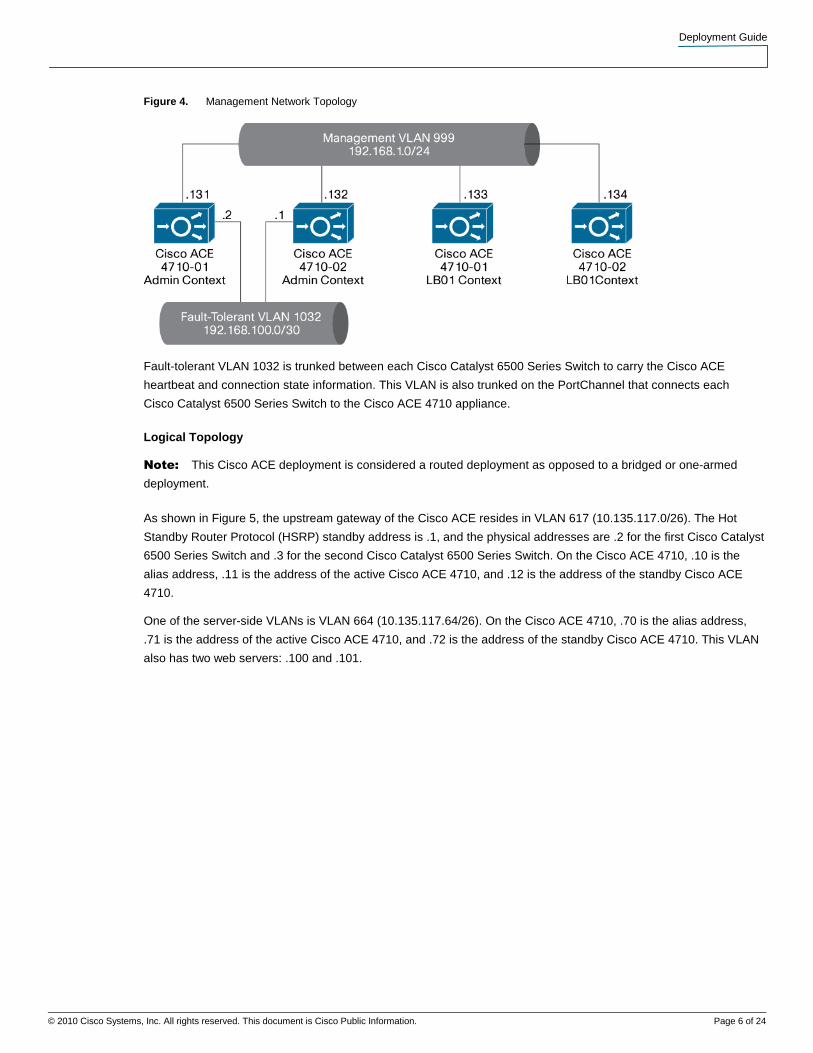
As shown in Figure 4, the management VLAN 999 connects to the Admin context as well as the LB01 context. Since
this VLAN is actively shared by each Cisco ACE 4710, the command shared-vlan-hostid is applied to the Admin
context to avoid any MAC-address duplication errors between the Cisco ACE 4710 appliances.
shared-vlan-hostid 1
peer shared-vlan-hostid 2
Note: See the Cisco ACE 4710 Command Reference for more information about the shared-vlan-hostid
command:
http://www.cisco.com/en/US/docs/app_ntwk_services/data_center_app_services/ace_appliances/vA3_1_0/comman
d/reference/config.html#wp1447465.
Deployment Guide
© 2010 Cisco Systems, Inc. All rights reserved. This document is Cisco Public Information. Page 6 of 24
Figure 4. Management Network Topology
Fault-tolerant VLAN 1032 is trunked between each Cisco Catalyst 6500 Series Switch to carry the Cisco ACE
heartbeat and connection state information. This VLAN is also trunked on the PortChannel that connects each
Cisco Catalyst 6500 Series Switch to the Cisco ACE 4710 appliance.
Logical Topology
Note: This Cisco ACE deployment is considered a routed deployment as opposed to a bridged or one-armed
deployment.
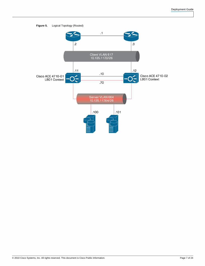
As shown in Figure 5, the upstream gateway of the Cisco ACE resides in VLAN 617 (10.135.117.0/26). The Hot
Standby Router Protocol (HSRP) standby address is .1, and the physical addresses are .2 for the first Cisco Catalyst
6500 Series Switch and .3 for the second Cisco Catalyst 6500 Series Switch. On the Cisco ACE 4710, .10 is the
alias address, .11 is the address of the active Cisco ACE 4710, and .12 is the address of the standby Cisco ACE
4710.
One of the server-side VLANs is VLAN 664 (10.135.117.64/26). On the Cisco ACE 4710, .70 is the alias address,
.71 is the address of the active Cisco ACE 4710, and .72 is the address of the standby Cisco ACE 4710. This VLAN
also has two web servers: .100 and .101.
Deployment Guide
© 2010 Cisco Systems, Inc. All rights reserved. This document is Cisco Public Information. Page 7 of 24
Figure 5. Logical Topology (Routed)
Deployment Guide
© 2010 Cisco Systems, Inc. All rights reserved. This document is Cisco Public Information. Page 8 of 24
High Availability and Fault Tolerance
Quality of Service
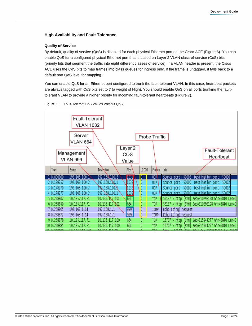
By default, quality of service (QoS) is disabled for each physical Ethernet port on the Cisco ACE (Figure 6). You can
enable QoS for a configured physical Ethernet port that is based on Layer 2 VLAN class-of-service (CoS) bits
(priority bits that segment the traffic into eight different classes of service). If a VLAN header is present, the Cisco
ACE uses the CoS bits to map frames into class queues for ingress only. If the frame is untagged, it falls back to a
default port QoS level for mapping.
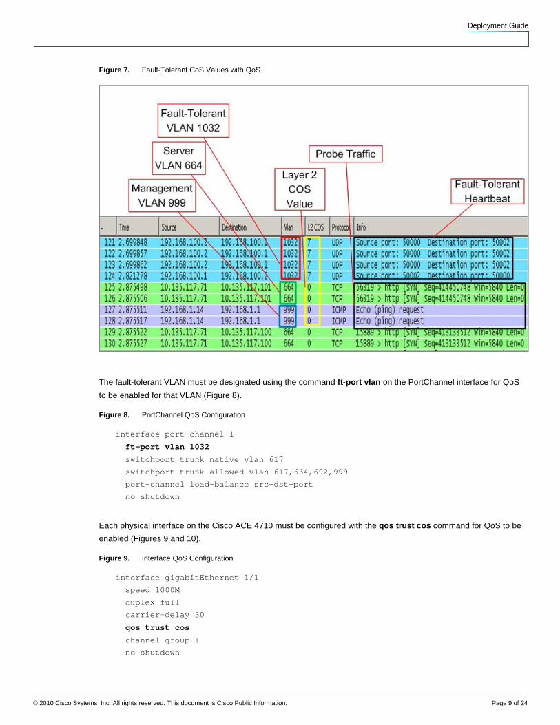
You can enable QoS for an Ethernet port configured to trunk the fault-tolerant VLAN. In this case, heartbeat packets
are always tagged with CoS bits set to 7 (a weight of High). You should enable QoS on all ports trunking the fault-
tolerant VLAN to provide a higher priority for incoming fault-tolerant heartbeats (Figure 7).
Figure 6. Fault-Tolerant CoS Values Without QoS
Deployment Guide
© 2010 Cisco Systems, Inc. All rights reserved. This document is Cisco Public Information. Page 9 of 24
Figure 7. Fault-Tolerant CoS Values with QoS
The fault-tolerant VLAN must be designated using the command ft-port vlan on the PortChannel interface for QoS
to be enabled for that VLAN (Figure 8).
Figure 8. PortChannel QoS Configuration
interface port-channel 1
ft-port vlan 1032
switchport trunk native vlan 617
switchport trunk allowed vlan 617,664,692,999
port-channel load-balance src-dst-port
no shutdown
Each physical interface on the Cisco ACE 4710 must be configured with the qos trust cos command for QoS to be
enabled (Figures 9 and 10).
Figure 9. Interface QoS Configuration
interface gigabitEthernet 1/1
speed 1000M
duplex full
carrier-delay 30
qos trust cos
channel-group 1
no shutdown
Deployment Guide
© 2010 Cisco Systems, Inc. All rights reserved. This document is Cisco Public Information. Page 10 of 24
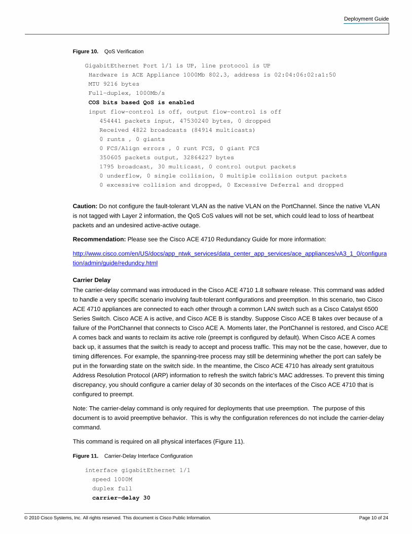
Figure 10. QoS Verification
GigabitEthernet Port 1/1 is UP, line protocol is UP
Hardware is ACE Appliance 1000Mb 802.3, address is 02:04:06:02:a1:50
MTU 9216 bytes
Full-duplex, 1000Mb/s
COS bits based QoS is enabled
input flow-control is off, output flow-control is off
454441 packets input, 47530240 bytes, 0 dropped
Received 4822 broadcasts (84914 multicasts)
0 runts , 0 giants
0 FCS/Align errors , 0 runt FCS, 0 giant FCS
350605 packets output, 32864227 bytes
1795 broadcast, 30 multicast, 0 control output packets
0 underflow, 0 single collision, 0 multiple collision output packets
0 excessive collision and dropped, 0 Excessive Deferral and dropped
Caution: Do not configure the fault-tolerant VLAN as the native VLAN on the PortChannel. Since the native VLAN
is not tagged with Layer 2 information, the QoS CoS values will not be set, which could lead to loss of heartbeat
packets and an undesired active-active outage.
Recommendation: Please see the Cisco ACE 4710 Redundancy Guide for more information:
http://www.cisco.com/en/US/docs/app_ntwk_services/data_center_app_services/ace_appliances/vA3_1_0/configura
tion/admin/guide/redundcy.html
Carrier Delay
The carrier-delay command was introduced in the Cisco ACE 4710 1.8 software release. This command was added
to handle a very specific scenario involving fault-tolerant configurations and preemption. In this scenario, two Cisco
ACE 4710 appliances are connected to each other through a common LAN switch such as a Cisco Catalyst 6500
Series Switch. Cisco ACE A is active, and Cisco ACE B is standby. Suppose Cisco ACE B takes over because of a
failure of the PortChannel that connects to Cisco ACE A. Moments later, the PortChannel is restored, and Cisco ACE
A comes back and wants to reclaim its active role (preempt is configured by default). When Cisco ACE A comes
back up, it assumes that the switch is ready to accept and process traffic. This may not be the case, however, due to
timing differences. For example, the spanning-tree process may still be determining whether the port can safely be
put in the forwarding state on the switch side. In the meantime, the Cisco ACE 4710 has already sent gratuitous
Address Resolution Protocol (ARP) information to refresh the switch fabric’s MAC addresses. To prevent this timing
discrepancy, you should configure a carrier delay of 30 seconds on the interfaces of the Cisco ACE 4710 that is
configured to preempt.
Note: The carrier-delay command is only required for deployments that use preemption. The purpose of this
document is to avoid preemptive behavior. This is why the configuration references do not include the carrier-delay
command.
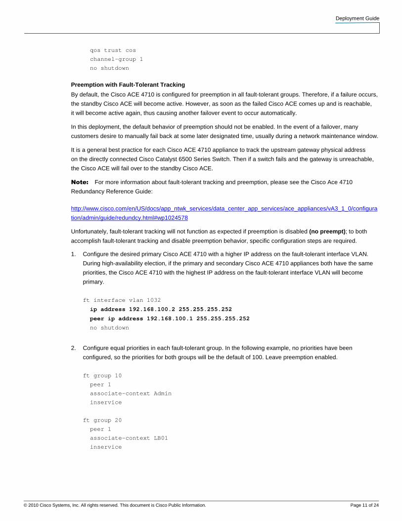
This command is required on all physical interfaces (Figure 11).
Figure 11. Carrier-Delay Interface Configuration
interface gigabitEthernet 1/1
speed 1000M
duplex full
carrier-delay 30
Deployment Guide
© 2010 Cisco Systems, Inc. All rights reserved. This document is Cisco Public Information. Page 11 of 24
qos trust cos
channel-group 1
no shutdown
Preemption with Fault-Tolerant Tracking
By default, the Cisco ACE 4710 is configured for preemption in all fault-tolerant groups. Therefore, if a failure occurs,
the standby Cisco ACE will become active. However, as soon as the failed Cisco ACE comes up and is reachable,
it will become active again, thus causing another failover event to occur automatically.
In this deployment, the default behavior of preemption should not be enabled. In the event of a failover, many
customers desire to manually fail back at some later designated time, usually during a network maintenance window.
It is a general best practice for each Cisco ACE 4710 appliance to track the upstream gateway physical address
on the directly connected Cisco Catalyst 6500 Series Switch. Then if a switch fails and the gateway is unreachable,
the Cisco ACE will fail over to the standby Cisco ACE.
Note: For more information about fault-tolerant tracking and preemption, please see the Cisco Ace 4710
Redundancy Reference Guide:
http://www.cisco.com/en/US/docs/app_ntwk_services/data_center_app_services/ace_appliances/vA3_1_0/configura
tion/admin/guide/redundcy.html#wp1024578
Unfortunately, fault-tolerant tracking will not function as expected if preemption is disabled (no preempt); to both
accomplish fault-tolerant tracking and disable preemption behavior, specific configuration steps are required.
1. Configure the desired primary Cisco ACE 4710 with a higher IP address on the fault-tolerant interface VLAN.
During high-availability election, if the primary and secondary Cisco ACE 4710 appliances both have the same
priorities, the Cisco ACE 4710 with the highest IP address on the fault-tolerant interface VLAN will become
primary.
ft interface vlan 1032
ip address 192.168.100.2 255.255.255.252
peer ip address 192.168.100.1 255.255.255.252
no shutdown
2. Configure equal priorities in each fault-tolerant group. In the following example, no priorities have been
configured, so the priorities for both groups will be the default of 100. Leave preemption enabled.
ft group 10
peer 1
associate-context Admin
inservice
ft group 20
peer 1
associate-context LB01
inservice
Deployment Guide
© 2010 Cisco Systems, Inc. All rights reserved. This document is Cisco Public Information. Page 12 of 24
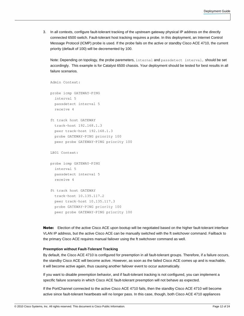
3. In all contexts, configure fault-tolerant tracking of the upstream gateway physical IP address on the directly
connected 6500 switch. Fault-tolerant host tracking requires a probe. In this deployment, an Internet Control
Message Protocol (ICMP) probe is used. If the probe fails on the active or standby Cisco ACE 4710, the current
priority (default of 100) will be decremented by 100.
Note: Depending on topology, the probe paremeters, internal and passdetect interval, should be set
accordingly. This example is for Catalyst 6500 chassis. Your deployment should be tested for best results in all
failure scenarios.
Admin Context:
probe icmp GATEWAY-PING
interval 5
passdetect interval 5
receive 4
ft track host GATEWAY
track-host 192.168.1.3
peer track-host 192.168.1.3
probe GATEWAY-PING priority 100
peer probe GATEWAY-PING priority 100
LB01 Context:
probe icmp GATEWAY-PING
interval 5
passdetect interval 5
receive 4
ft track host GATEWAY
track-host 10.135.117.2
peer track-host 10.135.117.3
probe GATEWAY-PING priority 100
peer probe GATEWAY-PING priority 100
Note: Election of the active Cisco ACE upon bootup will be negotiated based on the higher fault-tolerant interface
VLAN IP address, but the active Cisco ACE can be manually switched with the ft switchover command. Failback to
the primary Cisco ACE requires manual failover using the ft switchover command as well.
Preemption without Fault-Tolerant Tracking
By default, the Cisco ACE 4710 is configured for preemption in all fault-tolerant groups. Therefore, if a failure occurs,
the standby Cisco ACE will become active. However, as soon as the failed Cisco ACE comes up and is reachable,
it will become active again, thus causing another failover event to occur automatically.
If you want to disable preemption behavior, and if fault-tolerant tracking is not configured, you can implement a
specific failure scenario in which Cisco ACE fault-tolerant preemption will not behave as expected.
If the PortChannel connected to the active Cisco ACE 4710 fails, then the standby Cisco ACE 4710 will become
active since fault-tolerant heartbeats will no longer pass. In this case, though, both Cisco ACE 4710 appliances
Deployment Guide
© 2010 Cisco Systems, Inc. All rights reserved. This document is Cisco Public Information. Page 13 of 24
consider themselves active, but since one is completely cut off, it does not cause any problems. After the
PortChannel is restored to the original active Cisco ACE 4710, the appliance will again take over as the active
device regardless of preemption settings on the fault-tolerant groups. To make preemption behave as expected
(no preemption), use fault-tolerant tracking to reduce the priority level of the failed Cisco ACE so that it will not take
over as the active device after it is restored.
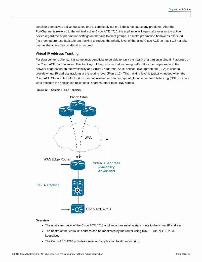
Virtual IP Address Tracking
For data center resiliency, it is sometimes beneficial to be able to track the health of a particular virtual IP address on
the Cisco ACE load balancer. This tracking will help ensure that incoming traffic takes the proper route at the
network edge based on the availability of a virtual IP address. An IP service-level agreement (SLA) is used to
provide virtual IP address tracking at the routing level (Figure 12). This tracking level is typically needed when the
Cisco ACE Global Site Selector (GSS) in not involved or another type of global server load balancing (GSLB) cannot
work because the application relies on IP address rather than DNS names.
Figure 12. Sample IP SLA Topology
Overview
● The upstream router of the Cisco ACE 4710 appliance can install a static route to the virtual IP address.
● The health of the virtual IP address can be monitored by the router using ICMP, TCP, or HTTP GET
keepalives.
● The Cisco ACE 4710 provides server and application health monitoring.

Deployment Guide
© 2010 Cisco Systems, Inc. All rights reserved. This document is Cisco Public Information. Page 14 of 24
● The same virtual IP addresses can be advertised from multiple data centers.
● Layer 3 routing protocols are used for route propagation and content request routing.
● Disaster recovery is provided by network convergence.
Advantages
● Tracking can be used track virtual IP addresses that are behind a Network Address Translation (NAT)
device (firewall).
● Segmentation is provided for security and load-balancing functions. Inspections do not need to be enabled
on the distribution devices or Cisco ACE.
● Routing protocol and environment tuning can account for very fast convergence during failure conditions.
● This design can be used during application migration in which virtual IP addresses cannot be changed.
Disadvantages
● IP SLA and tracking cannot track IP addresses at the port level; it cannot track individual port availability
of a virtual IP address with multiple ports. This is a limitation of route health injection (RHI) as well.
● New virtual IP address implementation with multiple network touchpoints may be administratively challenging.
● Troubleshooting between multiple routing domains and multiple service devices can be challenging.
● Tracking is limited to a maximum of 500 tracked instances (depending on the code version).
Implementation
Figure 13. IP SLA Implementation
● Configure the upstream router to inject a 32-bit host route as a static route in the routing table using IP SLA
and tracking.
● The router injects or removes the route based on the health of the back-end servers (checked with ICMP,
TCP or HTTP GET).
Note: See the “Configuration Reference” section later in this document for the IP SLA configuration template.
Deployment Guide
© 2010 Cisco Systems, Inc. All rights reserved. This document is Cisco Public Information. Page 15 of 24
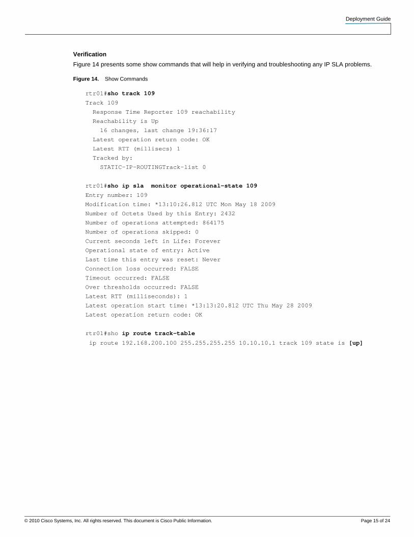
Verification
Figure 14 presents some show commands that will help in verifying and troubleshooting any IP SLA problems.
Figure 14. Show Commands
rtr01#sho track 109
Track 109
Response Time Reporter 109 reachability
Reachability is Up
16 changes, last change 19:36:17
Latest operation return code: OK
Latest RTT (millisecs) 1
Tracked by:
STATIC-IP-ROUTINGTrack-list 0
rtr01#sho ip sla monitor operational-state 109
Entry number: 109
Modification time: *13:10:26.812 UTC Mon May 18 2009
Number of Octets Used by this Entry: 2432
Number of operations attempted: 864175
Number of operations skipped: 0
Current seconds left in Life: Forever
Operational state of entry: Active
Last time this entry was reset: Never
Connection loss occurred: FALSE
Timeout occurred: FALSE
Over thresholds occurred: FALSE
Latest RTT (milliseconds): 1
Latest operation start time: *13:13:20.812 UTC Thu May 28 2009
Latest operation return code: OK
rtr01#sho ip route track-table
ip route 192.168.200.100 255.255.255.255 10.10.10.1 track 109 state is [up]
Deployment Guide
© 2010 Cisco Systems, Inc. All rights reserved. This document is Cisco Public Information. Page 16 of 24
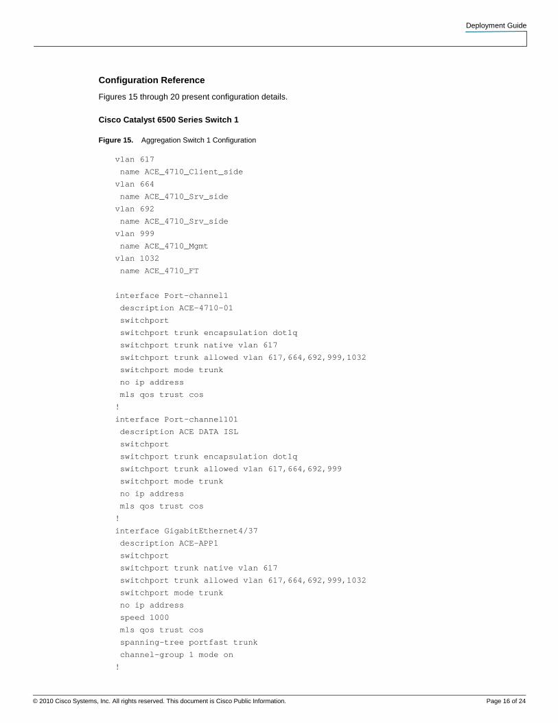
Configuration Reference
Figures 15 through 20 present configuration details.
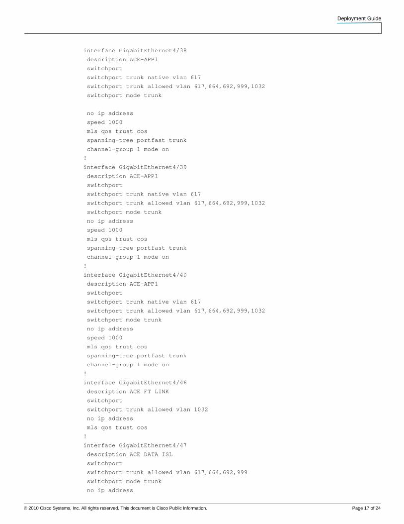
Cisco Catalyst 6500 Series Switch 1
Figure 15. Aggregation Switch 1 Configuration
vlan 617
name ACE_4710_Client_side
vlan 664
name ACE_4710_Srv_side
vlan 692
name ACE_4710_Srv_side
vlan 999
name ACE_4710_Mgmt
vlan 1032
name ACE_4710_FT
interface Port-channel1
description ACE-4710-01
switchport
switchport trunk encapsulation dot1q
switchport trunk native vlan 617
switchport trunk allowed vlan 617,664,692,999,1032
switchport mode trunk
no ip address
mls qos trust cos
!
interface Port-channel101
description ACE DATA ISL
switchport
switchport trunk encapsulation dot1q
switchport trunk allowed vlan 617,664,692,999
switchport mode trunk
no ip address
mls qos trust cos
!
interface GigabitEthernet4/37
description ACE-APP1
switchport
switchport trunk native vlan 617
switchport trunk allowed vlan 617,664,692,999,1032
switchport mode trunk
no ip address
speed 1000
mls qos trust cos
spanning-tree portfast trunk
channel-group 1 mode on
!
Deployment Guide
© 2010 Cisco Systems, Inc. All rights reserved. This document is Cisco Public Information. Page 17 of 24
interface GigabitEthernet4/38
description ACE-APP1
switchport
switchport trunk native vlan 617
switchport trunk allowed vlan 617,664,692,999,1032
switchport mode trunk
no ip address
speed 1000
mls qos trust cos
spanning-tree portfast trunk
channel-group 1 mode on
!
interface GigabitEthernet4/39
description ACE-APP1
switchport
switchport trunk native vlan 617
switchport trunk allowed vlan 617,664,692,999,1032
switchport mode trunk
no ip address
speed 1000
mls qos trust cos
spanning-tree portfast trunk
channel-group 1 mode on
!
interface GigabitEthernet4/40
description ACE-APP1
switchport
switchport trunk native vlan 617
switchport trunk allowed vlan 617,664,692,999,1032
switchport mode trunk
no ip address
speed 1000
mls qos trust cos
spanning-tree portfast trunk
channel-group 1 mode on
!
interface GigabitEthernet4/46
description ACE FT LINK
switchport
switchport trunk allowed vlan 1032
no ip address
mls qos trust cos
!
interface GigabitEthernet4/47
description ACE DATA ISL
switchport
switchport trunk allowed vlan 617,664,692,999
switchport mode trunk
no ip address
Deployment Guide
© 2010 Cisco Systems, Inc. All rights reserved. This document is Cisco Public Information. Page 18 of 24
mls qos trust cos
channel-group 101 mode on
!
interface GigabitEthernet4/48
description ACE DATA ISL
switchport
switchport trunk allowed vlan 617,664,692,999
switchport mode trunk
no ip address
mls qos trust cos
channel-group 101 mode on
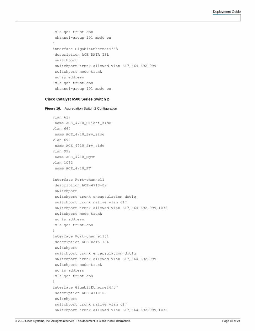
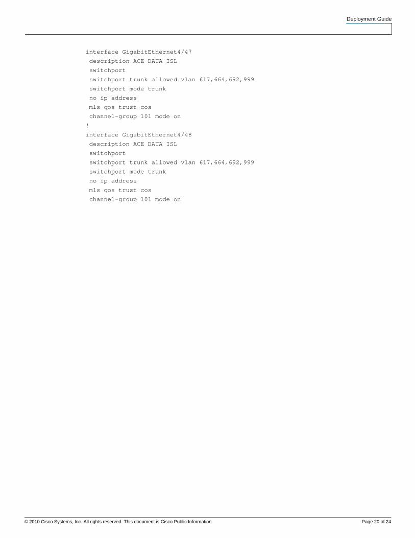
Cisco Catalyst 6500 Series Switch 2
Figure 16. Aggregation Switch 2 Configuration
vlan 617
name ACE_4710_Client_side
vlan 664
name ACE_4710_Srv_side
vlan 692
name ACE_4710_Srv_side
vlan 999
name ACE_4710_Mgmt
vlan 1032
name ACE_4710_FT
interface Port-channel1
description ACE-4710-02
switchport
switchport trunk encapsulation dot1q
switchport trunk native vlan 617
switchport trunk allowed vlan 617,664,692,999,1032
switchport mode trunk
no ip address
mls qos trust cos
!
interface Port-channel101
description ACE DATA ISL
switchport
switchport trunk encapsulation dot1q
switchport trunk allowed vlan 617,664,692,999
switchport mode trunk
no ip address
mls qos trust cos
!
interface GigabitEthernet4/37
description ACE-4710-02
switchport
switchport trunk native vlan 617
switchport trunk allowed vlan 617,664,692,999,1032

Deployment Guide
© 2010 Cisco Systems, Inc. All rights reserved. This document is Cisco Public Information. Page 19 of 24
switchport mode trunk
no ip address
speed 1000
mls qos trust cos
spanning-tree portfast trunk
channel-group 1 mode on
!
interface GigabitEthernet4/38
description ACE-4710-02
switchport
switchport trunk native vlan 617
switchport trunk allowed vlan 617,664,692,999,1032
switchport mode trunk
no ip address
speed 1000
mls qos trust cos
spanning-tree portfast trunk
channel-group 1 mode on
!
interface GigabitEthernet4/39
description ACE-4710-02
switchport
switchport trunk native vlan 617
switchport trunk allowed vlan 617,664,692,999,1032
switchport mode trunk
no ip address
speed 1000
mls qos trust cos
spanning-tree portfast trunk
channel-group 1 mode on
!
interface GigabitEthernet4/40
description ACE-4710-02
switchport
switchport trunk native vlan 617
switchport trunk allowed vlan 617,664,692,999,1032
switchport mode trunk
no ip address
speed 1000
mls qos trust cos
spanning-tree portfast trunk
channel-group 1 mode on
!
interface GigabitEthernet4/46
description ACE FT LINK
switchport
switchport trunk allowed vlan 1032
no ip address
mls qos trust cos
!
Deployment Guide
© 2010 Cisco Systems, Inc. All rights reserved. This document is Cisco Public Information. Page 20 of 24
interface GigabitEthernet4/47
description ACE DATA ISL
switchport
switchport trunk allowed vlan 617,664,692,999
switchport mode trunk
no ip address
mls qos trust cos
channel-group 101 mode on
!
interface GigabitEthernet4/48
description ACE DATA ISL
switchport
switchport trunk allowed vlan 617,664,692,999
switchport mode trunk
no ip address
mls qos trust cos
channel-group 101 mode on
Deployment Guide
© 2010 Cisco Systems, Inc. All rights reserved. This document is Cisco Public Information. Page 21 of 24
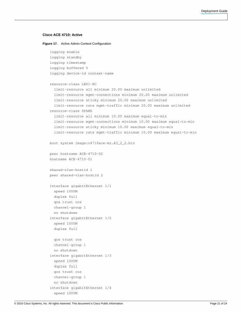
Cisco ACE 4710: Active
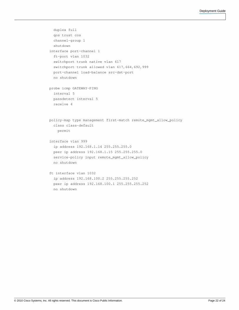
Figure 17. Active Admin Context Configuration
logging enable
logging standby
logging timestamp
logging buffered 5
logging device-id context-name
resource-class LB01-RC
limit-resource all minimum 20.00 maximum unlimited
limit-resource mgmt-connections minimum 20.00 maximum unlimited
limit-resource sticky minimum 20.00 maximum unlimited
limit-resource rate mgmt-traffic minimum 20.00 maximum unlimited
resource-class SPARE
limit-resource all minimum 10.00 maximum equal-to-min
limit-resource mgmt-connections minimum 10.00 maximum equal-to-min
limit-resource sticky minimum 10.00 maximum equal-to-min
limit-resource rate mgmt-traffic minimum 10.00 maximum equal-to-min
boot system image:c4710ace-mz.A3_2_2.bin
peer hostname ACE-4710-02
hostname ACE-4710-01
shared-vlan-hostid 1
peer shared-vlan-hostid 2
interface gigabitEthernet 1/1
speed 1000M
duplex full
qos trust cos
channel-group 1
no shutdown
interface gigabitEthernet 1/2
speed 1000M
duplex full
qos trust cos
channel-group 1
no shutdown
interface gigabitEthernet 1/3
speed 1000M
duplex full
qos trust cos
channel-group 1
no shutdown
interface gigabitEthernet 1/4
speed 1000M
Deployment Guide
© 2010 Cisco Systems, Inc. All rights reserved. This document is Cisco Public Information. Page 22 of 24
duplex full
qos trust cos
channel-group 1
shutdown
interface port-channel 1
ft-port vlan 1032
switchport trunk native vlan 617
switchport trunk allowed vlan 617,664,692,999
port-channel load-balance src-dst-port
no shutdown
probe icmp GATEWAY-PING
interval 5
passdetect interval 5
receive 4
policy-map type management first-match remote_mgmt_allow_policy
class class-default
permit
interface vlan 999
ip address 192.168.1.14 255.255.255.0
peer ip address 192.168.1.15 255.255.255.0
service-policy input remote_mgmt_allow_policy
no shutdown
ft interface vlan 1032
ip address 192.168.100.2 255.255.255.252
peer ip address 192.168.100.1 255.255.255.252
no shutdown
Deployment Guide
© 2010 Cisco Systems, Inc. All rights reserved. This document is Cisco Public Information. Page 23 of 24
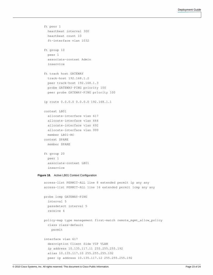
ft peer 1
heartbeat interval 300
heartbeat count 10
ft-interface vlan 1032
ft group 10
peer 1
associate-context Admin
inservice
ft track host GATEWAY
track-host 192.168.1.2
peer track-host 192.168.1.3
probe GATEWAY-PING priority 100
peer probe GATEWAY-PING priority 100
ip route 0.0.0.0 0.0.0.0 192.168.1.1
context LB01
allocate-interface vlan 617
allocate-interface vlan 664
allocate-interface vlan 692
allocate-interface vlan 999
member LB01-RC
context SPARE
member SPARE
ft group 20
peer 1
associate-context LB01
inservice
Figure 18. Active LB01 Context Configuration
access-list PERMIT-ALL line 8 extended permit ip any any
access-list PERMIT-ALL line 16 extended permit icmp any any
probe icmp GATEWAY-PING
interval 5
passdetect interval 5
receive 4
policy-map type management first-match remote_mgmt_allow_policy
class class-default
permit
interface vlan 617
description Client Side VIP VLAN
ip address 10.135.117.11 255.255.255.192
alias 10.135.117.10 255.255.255.192
peer ip address 10.135.117.12 255.255.255.192
Deployment Guide
© 2010 Cisco Systems, Inc. All rights reserved. This document is Cisco Public Information. Page 24 of 24
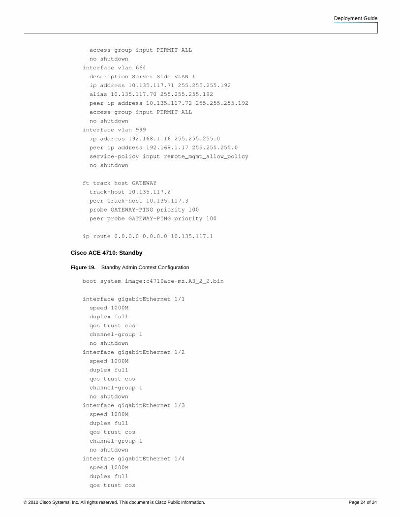
access-group input PERMIT-ALL
no shutdown
interface vlan 664
description Server Side VLAN 1
ip address 10.135.117.71 255.255.255.192
alias 10.135.117.70 255.255.255.192
peer ip address 10.135.117.72 255.255.255.192
access-group input PERMIT-ALL
no shutdown
interface vlan 999
ip address 192.168.1.16 255.255.255.0
peer ip address 192.168.1.17 255.255.255.0
service-policy input remote_mgmt_allow_policy
no shutdown
ft track host GATEWAY
track-host 10.135.117.2
peer track-host 10.135.117.3
probe GATEWAY-PING priority 100
peer probe GATEWAY-PING priority 100
ip route 0.0.0.0 0.0.0.0 10.135.117.1
Cisco ACE 4710: Standby
Figure 19. Standby Admin Context Configuration
boot system image:c4710ace-mz.A3_2_2.bin
interface gigabitEthernet 1/1
speed 1000M
duplex full
qos trust cos
channel-group 1
no shutdown
interface gigabitEthernet 1/2
speed 1000M
duplex full
qos trust cos
channel-group 1
no shutdown
interface gigabitEthernet 1/3
speed 1000M
duplex full
qos trust cos
channel-group 1
no shutdown
interface gigabitEthernet 1/4
speed 1000M
duplex full
qos trust cos
Deployment Guide
© 2010 Cisco Systems, Inc. All rights reserved. This document is Cisco Public Information. Page 25 of 24
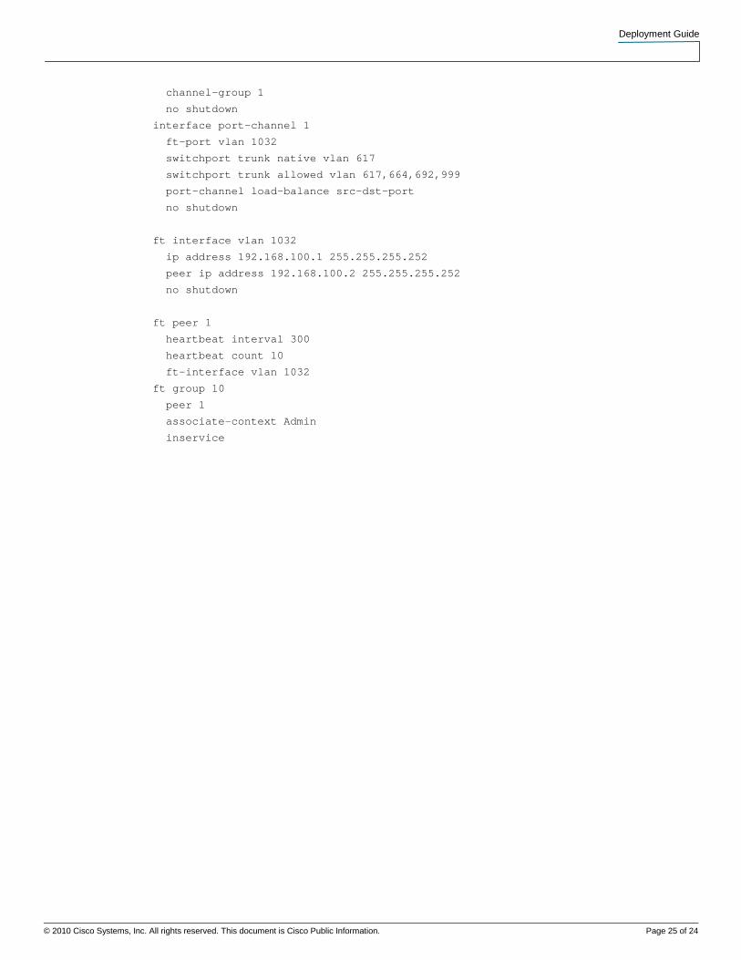
channel-group 1
no shutdown
interface port-channel 1
ft-port vlan 1032
switchport trunk native vlan 617
switchport trunk allowed vlan 617,664,692,999
port-channel load-balance src-dst-port
no shutdown
ft interface vlan 1032
ip address 192.168.100.1 255.255.255.252
peer ip address 192.168.100.2 255.255.255.252
no shutdown
ft peer 1
heartbeat interval 300
heartbeat count 10
ft-interface vlan 1032
ft group 10
peer 1
associate-context Admin
inservice
Deployment Guide
© 2010 Cisco Systems, Inc. All rights reserved. This document is Cisco Public Information. Page 26 of 24
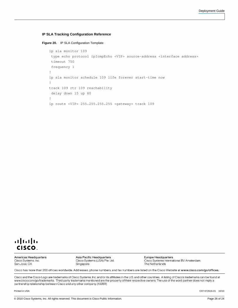
IP SLA Tracking Configuration Reference
Figure 20. IP SLA Configuration Template
ip sla monitor 109
type echo protocol ipIcmpEcho <VIP> source-address <interface address>
timeout 750
frequency 1
!
ip sla monitor schedule 109 life forever start-time now
!
track 109 rtr 109 reachability
delay down 15 up 60
!
ip route <VIP> 255.255.255.255 <gateway> track 109
Printed in USA C07-572616-01 10/10