cisco certified simplified
DESCRIPTION
its a simplified cisco book for the study of ccna.TRANSCRIPT

1
CISCO CERTIFIED NETWORK ASSOCIATE
Revision 1.0 Netmax Technologies is an independent entity from Cisco Systems, Inc. and is not affiliated with Cisco Systems, Inc. in any manner. This study guide and/or material is not sponsored by, endorsed by, or affiliated with Cisco Systems, Inc. Cisco®, Cisco Systems®, CCDA™, CCNA™, CCDP™, CCNP™, CCIE™, CCSI™ the Cisco Systems logo and the CCIE logo are trademarks or registered trademarks of Cisco Systems, Inc. in the United States and certain other countries. All other trademarks are trademarks of their respective owners.
__________________________________________________________________________

2
__________________________________________________________________________
_______________________________________________________________________________ I N T R O D U C T I O N
Routers manufactured by Cisco Systems currently carry the vast majority of Internet traffic worldwide. Cisco routers are powerful devices specifically designed to move information quickly and efficiently between networks. The comprehensive family of Cisco routers range in size and capacity from small, modular access routers designed to power small offices and departments to powerful models designed to enable entire cities.
C O U R S E I N T R O D U C T I O N In this course we are going a study a lot of technologies and our objective will be: Create large sized LAN network Implement WAN connectivity between multiple locations Routing traffic between different locations Secure networks and Control traffic flow Connect organization to ISP Implement new protocols like IPv6 Wi-Fi LAN networks To achieve all these objectives we must know about following technologies Switching VLAN, Inter VLAN, Frame Tagging, Spanning Tree, Port Security, Ether Channel Routing Static, Dynamic, RIP, EIGRP, OSPF Wan Point-to-point Leased lines, Radio Links, Frame Relay Security Access-lists, CBAC, VPN, NAT To perform all these tasks on Router and Switches some prerequisites are required OSI and TCP/IP model IPv4 basics & Subnetting Router and Switch Administration IPv6: Implementation & Migration The course is divided in 14 Chapters. The details are given in the Contents table.

3
__________________________________________________________________________
C O U R S E C O N T E N T S Introduction…………………………………………………………………………………… Networks and its Components…………………………………………………………. OSI Model……………………………………………………………………………... NIC and its Operation………………………………………………………………….. Ethernet – Most common technology …………………………………………………. LAN segmentation in Ethernet………………………………………………………… Cisco Hierarchical Model……………………………………………………………… TCP/IP………………………………………………………………………………………... TCP/IP model………………………………………………………………………….. Application Layer Protocols…………………………………………………………… Transport layer TCP/UDP …………………………………………………………….. Internet Protocols………………………………………………………………………. Other protocols………………………………………………………………………..... IP addressing & Subnetting…………………………………………………………………… IP Addressing Rules…………………………………………………………………… Subnetting……………………………………………………………………………… VLSM…………………………………………………………………………………. Zero Subnet……………………………………………………………………………. IP Classless……………………………………………………………………………. Router Administration……………………………………………………………………….. Router Architecture…………………………………………………………………… Router Interfaces and Ports…………………………………………………………… Types of Router……………………………………………………………………………… Router Access Methods………………………………………………………………. Router Modes…………………………………………………………………………. Router Commands…………………………………………………………………………… Configuring Passwords……………………………………………………………….. Managing Configuration………………………………………………………………. Banners………………………………………………………………………………... Router Clock & NTP………………………………………………………………….. Logging ………………………………………………………………………………. Interface Configuration………………………………………………………………..

4
__________________________________________________________________________
Display Interface Status………………………………………………………………. Telnet, SSH, SDM……………………………………………………………………. Advanced Router Management……………………………………………………………… Router boot sequence…………………………………………………………………. Router booting sources………………………………………………………….…….. Configuration register………………………………………………………….……… Breaking passwords………………………………………………………….….…….. Backup & Upgrade IOS ………………………………………………………….…… Backup & restore Configuration………………………………………………….…… Resolving Hostnames……………………………………………………….…….…… Managing Telnet ………………………………………………………………….…… Using CDP………………………………………………………………….…….…… IP routing………………………………………………………………….…….…… Introduction………………………………………………………………….…….…… IP routing process………………………………………………………………….…….…… Types of Routing………………………………………………………………….…….…… Static………………………………………………………………….…….…… Dynamic………………………………………………………………….…….…… Static Routing………………………………………………………………….…….…… Default Routing………………………………………………………………….…….…… Floating Static Route………………………………………………………………….…….…… Configuration using SDM Types of Dynamic Routing…………………………………………………………………. Distance Vector………………………………………………………………….… Link State………………………………………………………………….…….…… Distance vector operation………………………………………………………………….… Loop Avoidance methods…………………………………………………………………. Link State Operation………………………………………………………………….…… Autonomous Systems………………………………………………………………….… Routing Information Protocol…………………………………………………………… Basic Configuration………………………………………………………………… Passive interfaces…………………………………………………………………. Debugging RIP………………………………………………………………….… Configuration using SDM Enhanced Interior Gateway Routing Protocol…………………………………………… Protocol Dependent Module……………………………………………………… Reliable Transport Protocol……………………………………………………… Diffusing Update Algorithm (DUAL) …………………………………………… Basic Configuration……………………………………………………… Bandwidth metric tuning……………………………………………………… Successor and Feasible successor………………………………………………… Advertised distance and Feasible distance……………………………………… Open Shortest Path First………………………………………………………………….

5
__________________________________________________________________________
OSPF features………………………………………………………………….… Hierarchical model…………………………………………………………………. OSPF terms………………………………………………………………….…….… Router ID………………………………………………………………….…….… LSA flooding………………………………………………………………….…….… Designated Router ………………………………………………………… Backup designated router…………………………………………………… Configuration………………………………………………………………….…… Display Information & debugging…………………………………………………… Configuration using SDM…………………………………………………………………… Redistribution………………………………………………………………….…………. Route Summarization………………………………………………………………….…… LAN Switching………………………………………………………………….…… Switch Operation………………………………………………………………….…… Types Of switches………………………………………………………………….…… Selection Criteria for selection of switch………………………………………………… Basic switch administration……………………………………………………………… VLAN ………………………………………………………………….………………. Frame tagging………………………………………………………………….…… VLAN Trunking Protocol………………………………………………………………… Inter VLAN ………………………………………………………………….………….. Cisco Network Assistant…………………………………………………………………. Voice VLAN ………………………………………………………………….…… Spanning Tree Protocol………………………………………………………………….…… STP terms………………………………………………………………….…… Operation………………………………………………………………….…… Port-fast………………………………………………………………….…… Uplink-fast………………………………………………………………….…… Backbone-fast ………………………………………………………………….…… RSTP………………………………………………………………….…… Port Security………………………………………………………………….…… Ether Channel………………………………………………………………….…… Using CAN………………………………………………………………….…… Access Control Lists………………………………………………………………….…… Security Threats………………………………………………………………….…… IOS security solutions…………………………………………………………………. Access Control Lists………………………………………………………………….…… Types of ACL………………………………………………………………….…… Standard ACL………………………………………………………………….…… Named ACL………………………………………………………………….…… VTY control using ACL…………………………………………………………………. Extended ACL………………………………………………………………….…… Time Based ACL………………………………………………………………….……

6
__________________________________________________________________________
CBAC………………………………………………………………….…… ACL configuration using SDM………………………………………………………… Network Address Translation………………………………………………………………….…… Introduction………………………………………………………………….…… NAT terms………………………………………………………………….…… Static NAT………………………………………………………………….…… Port based Static NAT………………………………………………………………….…… Dynamic NAT………………………………………………………………….…… Dynamic NAT using Overload…………………………………………………………… NAT using SDM………………………………………………………………….…… Wireless Technologies………………………………………………………………….…… Wireless Basics………………………………………………………………….…… NIC working………………………………………………………………….…… 802.11 Standards………………………………………………………………….…… Service Set………………………………………………………………….…… Service Set Identifier………………………………………………………………….…… Independent basic service set……………………………………………………… Basic service set………………………………………………………………….…… Extended service set……………………………………………………………… Cisco Unified Wireless Solutions…………………………………………………………… Wireless Security………………………………………………………………….………. WEP………………………………………………………………….…… WPA/WPA2………………………………………………………………….…… 802.1X………………………………………………………………….…… Internet Protocol version 6………………………………………………………………….… Introduction………………………………………………………………….…… Changes in comparison to IPv4………………………………………………………… IPv6 Header Format………………………………………………………………….…… IPV6 addressing………………………………………………………………….…… Auto-configuration………………………………………………………………….…… Basic Configuration on Router…………………………………………………………… Static routing………………………………………………………………….…… Dynamic routing ………………………………………………………………….…… RIPng………………………………………………………………….…… EIGRPv6………………………………………………………………….…… OPSFv3………………………………………………………………….…… Migration to IPv6………………………………………………………………….…… Dual Stacking………………………………………………………………….. IPv6 to IPv4 Tunnel……………………………………………………………… NAT-PT………………………………………………………………….…… Wide Area Networks………………………………………………………………….……

7
__________________________________________________________________________
WAN technologies………………………………………………………………….…… Selection Criteria for WAN networks…………………………………………………… WAN terms………………………………………………………………….…… WAN encapsulation………………………………………………………………….…… Point to Point WAN technologies………………………………………………………… Steps to setup P-t-P wan…………………………………………………………………. p-t-p topologies………………………………………………………………….… Router Configuration……………………………………………………………… Modem Configuration …………………………………………………………… HDLC & PPP………………………………………………………………….…… PPP authentication………………………………………………………………….…… Frame Relay basics………………………………………………………………….… Point to point frame relay……………………………………………………………… Multi-point Frame relay…………………………………………………………………. Frame relay traffic shaping……………………………………………………………… Configuration using SDM……………………………………………………………….

8
__________________________________________________________________________
NETWORKS AND COMPONENTS Network is the method to share hardware resources and software resources. We can share the resources with the help of operating system like windows, Linux, UNIX etc. To connect multiple networks we have to use internetworking devices like router, bridge, layer 3, switches etc. Administrator model for Networks We can say that there are four components which are required to create networks
1. Software 2. Protocol Stack 3. Network Interface Card 4. Media
Software Networking software can be divided in two categories:
Server software: - The software used to provide a particular service. Client software: - The software which is used to access service provided by server.

9
Design Considerations Server software and Client software should be compatible. Protocol stack must be same. Connectivity can be performed via switch/hub etc. If NIC standards are different then translational bridge is required. If media is different then Trans-Receiver is required.
__________________________________________________________________________

10
_________________________________________________________________________ OSI Model OSI model is the layer approach to design, develop and implement networks. OSI model provides following advantages: -
• Designing of network will be standards based. • Development time of new technologies will be reduced. • Devices from multiple vendors can communicate with each other. • Implementation and troubleshooting of network will be easier.
Application Layer: -
__________________________________________________________________________

11
__________________________________________________________________________
Application layer accepts data and forward into the protocol stack. It creates user interface between application software and protocol stack.
Presentation Layer: -
This layer decides presentation format of the data. It also able to performs other function like compression/decompression and encryption/decryption.
Session Layer: -
This layer initiate, maintain and terminate sessions between different applications. Due to this layer multiple application software can be executed at the same time.
Transport Layer: -
Transport layer is responsible for connection oriented and connection less communication. Transport layer also performs other functions like :-
Positive Acknowledgement & Response Error checking Flow Control Buffering Windowing Multiplexing Sequencing

12
Connection Oriented Communication
Connection less Communication
__________________________________________________________________________
Sender Receiver
Send Error checking Transport layer generates cyclic redundancy check (CRC) by using a polynomial and
forward the CRC value to destination in data. The other end will generate CRC according to data and match the generated CRC value with received value. If both are same, then data is accepted otherwise discarded.
Flow Control

13
__________________________________________________________________________
Flow control is used to control the flow of data during communication. For this purpose following methods are used: -
Buffering Buffer is the temporary storage area. All the data is stored in the buffer memory and
when communication ability is available the data is forward to another. Windowing Windowing is the maximum amounts of the data that can be send to destination
without receiving Acknowledgement. It limits the size of buffer. Multiplexing Multiplexing is used for multiple applications on same IP.
Sequencing Transport layer add sequence number to data, so that out of sequence data can be
detected and rearranged in proper manner. Positive Acknowledgement and Response When data is send to destination, the destination will reply with Acknowledgement
to indicate the positive reception of data. If Acknowledgement is not received within a specified time then the data is resend from buffer memory.
Network Layer
This layer performs function like logical addressing and path determination. Each networking device has a physical address that is MAC address. But logical addressing is easier to communicate on large size network. Logical addressing Logical addressing defines network address and host address. This type of addressing is used to simplify implementation of large network. Some examples of logical addressing are: - IP addresses, IPX addresses etc.
Path determination Network layer has different routing protocols like RIP, EIGRP, BGP, and ARP etc. to perform the path determination for different routing protocol. Its other responsibilities are: Fragmentation Quality of Service Header checksum Protocol Identification
Data Link Layer
The functions of Data Link layer are divided into two sub layers

14
__________________________________________________________________________
• Logical Link Control • Media Access Control
Logical Link Control defines the encapsulation that will be used by the NIC to delivered data to destination. Some examples of Logical Link Control are ARPA (Ethernet), 802.11 wi-fi.
Media Access Control defines methods to access the shared media and establish the identity with the help of MAC address. Some examples of Media Access Control are CSMA/CD, Token Passing.
Physical Layer
Physical Layer is responsible to communicate bits over the media this layer deals with the standard defined for media and signals. This layer may also perform modulation and demodulation as required.
______________________________________________________________ Devices at different Layers
Physical Layer Devices Hub, Modem, Media, DCE (Data comm. Equipment) CSU/DSU, Repeater, Media converter
Data Link Layer NIC, Switch, Bridge
Network Layer Device Router, Layer 3 Switch
All Layers Device PC, Firewall

15
______________________________________________________________________________
Data Encapsulation
Data => Segment => Packet => Frames => Bits
__________________________________________________________________________

16
LAN Technologies
_____________________________________________________________________________________
Ethernet Ethernet is the most popular LAN technology. It can support verity of media like copper (UTP, Coaxial, fiber optic). This technology supports wide range of speed from 10mbps to 10000 mbps. Ethernet at Logical Link Control To create logical link control Ethernet uses ARPA protocol also called IEEE802.3. Ethernet adds source MAC, destination MAC, error checking information and some other information to data. Ethernet encapsulation explain as follows
__________________________________________________________________________

17
Ethernet frame Preamble An alternating 1,0 pattern provides a 5MHz clock at the start of each packet, which allows the receiving devices to lock the incoming bit stream. Start Frame Delimiter (SFD)/Synch The preamble is seven octets and the SFD is one octet (synch). The SFD is 10101011, where the last pair of 1s allows the receiver to come into the alternating 1,0 pattern somewhere in the middle and still sync up and detect the beginning of the data. Length or type 802.3 uses a length field, but the Ethernet frame uses a type field to identify the network layer protocol. 802.3 cannot identify the upper-layer protocol and must be used with a proprietary LAN-IPX, for example Ethernet at Media Access Control Ethernet at Media Access Control layer uses CSMA/CD protocol to access the shared media. In these days, we use Ethernet with switches and in switches the technology is made CSMA/CA (Collision Avoidance). So this reason Ethernet is best compare with Token Ring, FDDI & Wi-Fi.
__________________________________________________________________________

18
CSMA/CD This algorithm runs when a collision occurs
__________________________________________________________________________

19
Varieties of Ethernet
10Mbit/s Ethernet
10BASE2 (also called ThinNet or Cheapernet): 50-ohm coaxial cable connects machines together, each machine using a T-adaptor to connect to its NIC. Requires terminators at each end. For many years this was the dominant Ethernet standard 10 Mbit/s.
10BASE-T: runs over four wires (two twisted pairs) on a Category 3 or Category 5 cable. A hub or switch sits in the middle and has a port for each node. This is also the configuration used for 100BASE-T and gigabit Ethernet. 10 Mbit/s.
Fast Ethernet
100BASE-T: A term for any of the three standard for 100 Mbit/s Ethernet over twisted pair cable.
100BASE-TX: Uses two pairs, but requires Category 5 cable. Similar star-shaped configuration to 10BASE-T. 100 Mbit/s.
100BASE-FX: 100 Mbit/s Ethernet over fibre.
Gigabit Ethernet
1000BASE-T: 1 Gbit/s over Category 5e copper cabling.
__________________________________________________________________________
20
1000BASE-SX: 1 Gbit/s over fiber.
1000BASE-LX: 1 Gbit/s over fiber. Optimized for longer distances over single-mode fiber.
1000BASE-CX: A short-haul solution (up to 25 m) for running 1 Gbit/s Ethernet over special copper cable. Predates 1000BASE-T, and now obsolete.
10-gigabit Ethernet
The 10-gigabit Ethernet family of standards encompasses media types for single-mode fibre (long haul), multi-mode fibre (up to 300 m), copper backplane (up to 1 m) and copper twisted pair (up to 100 m). It was first standardised as IEEE Std 802.3ae-2002, but is now included in IEEE Std 802.3-2008.
10GBASE-T: designed to support copper twisted pair was specified by the IEEE Std 802.3an-2006 which has been incorporated into the IEEE Std 802.3-2008.
____________________________________________________________________
Ethernet Cabling
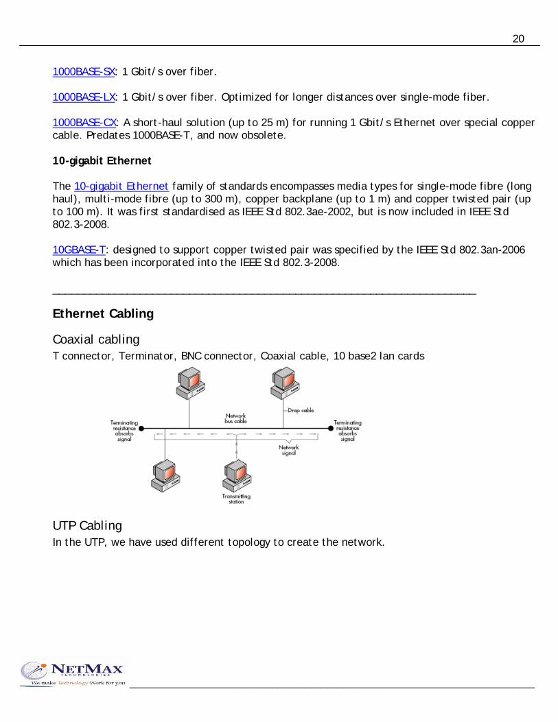
Coaxial cabling T connector, Terminator, BNC connector, Coaxial cable, 10 base2 lan cards
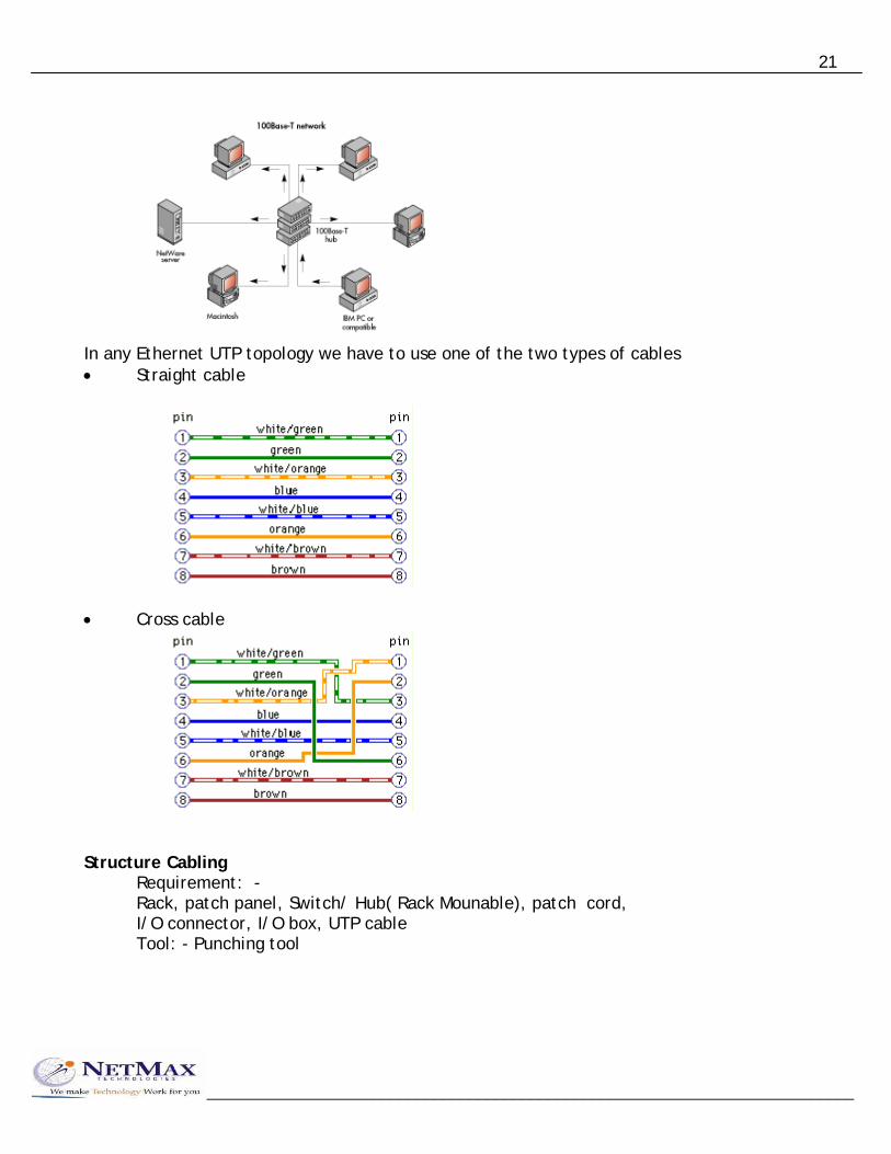
UTP Cabling In the UTP, we have used different topology to create the network.
__________________________________________________________________________
21
In any Ethernet UTP topology we have to use one of the two types of cables • Straight cable
• Cross cable
Structure Cabling
Requirement: - Rack, patch panel, Switch/ Hub( Rack Mounable), patch cord, I/O connector, I/O box, UTP cable Tool: - Punching tool
__________________________________________________________________________

22
_____________________________________________________________________
Problems of Ethernet technology • In Ethernet only one pc is able to send data at a time, due to this the bandwidth of
ethernet will be shared. • Not an equal access technology. • One pc will send data, which will be received by the all devices of network. Due to
this data communication will not be secured. • Collision will occur in the network and collision will lead to other problems like
latency, delay and reduce throughput. Latency – time duration to send packet from start to end. Throughput – speed to send data (output)
• All PCs will have single broadcast domain. Due to this the bandwidth will be reduced.
_____________________________________________________________________
LAN Segmentation of Ethernet Network There are three methods to perform LAN segmentation (1) LAN segmentation using bridge. (2) LAN segmentation using switches. (3) LAN segmentation using Routers. Collision domain A group of pc, in which collision can occur, is called a collision domain. Broadcast domain A group of pc in which broadcast message is delivered is called broadcast domain. LAN segmentation using bridge.
Existing
__________________________________________________________________________

23
New
__________________________________________________________________________
1st collision domain 2nd collision domain 3rd collision domain 1 broadcast domain
Working of Bridge: - Working of Bridge explains in following steps: - (i) Bridge can receives a frame in the buffer memory. (ii) The source MAC address of frame this stored to the bridging table.
Port number MAC address 1 2 3
(iii) According to the destination MAC address the frame will be forwarded or drop (a) If destination MAC address of the frame is known then frame is forwarded to the particular port. (b) If destination MAC address is unknown by bridging table then frame is forwarded to the all port except receiving port. (c) If destination MAC address is broadcast MAC address ff.ff.ff.ff.ff.ff. (d) If destination MAC address exist on the same port from which port received then frame is dropped.
LAN segmentation using Switches Due to perform Lan segmentation using switches. We have to remove hubs from the network and replace hub with switches the working of switches. The working of switch is exactly like a bridge. A multiport bridge can be used as a bridge. Multiple Collision domain = micro segmentation

24
1 Broadcast domain
__________________________________________________________________________
TIP: Switch’s working is similar to the bridge. Advantages of Switches: - (1) Bandwidth will not be shared and overall throughput will depend on wire speed of the switch. Wire speed is also called switching capacity measured in mbps or gbps. (2) Any time access technology. (3) One to one communication so that network will be more secures. (4) Switches will perform micro segmentation and no collision will occur in network.
Lan segmentation using router If we are facing high concession in the n/w due to the large number of broadcast then we can divide broadcast domain of network. So that number of broadcast message will be reduced.
1st Broadcast Domain 2nd Broadcast Domain 3rd Broadcast Domain

25
__________________________________________________________________________
We have to install router between multiple switches to divide the broadcast domain. Each broadcast domain has to used different network address and router will provide inter network communication between them.

26
Router Administration In this chapter we will study hardware architecture, Router Booting behavior, Command Line Usage and administration.
Pc Architecture
I/O Controller
K/B Controller
Keyboard
Display Card
Serial Parallel USB
Sound Card
Processor
RAM
Memory controller
HDD FD CDD
BIOS ROM
CMOS RAM
V.D.U
Router Architecture
__________________________________________________________________________
IOS
Processor
RAM
LAN
WAN
Ports
I/O Controller
Flash RAM O/S
NVRAM
BIOS ROM
Memory Controller
Components of ROUTER

27
__________________________________________________________________________
Router operation When a pc has to send data to a different network address, then data will be forwarded to the router. It will analysis IP address of the data and obtain a route from the routing table. According to the route data will be dropped, If route not available. Processor Speed: - 20 MHz to 1GHz Architecture: - RISC Reduce Instruction set computer Manufacturers: - Motorola, IBM, Power PC, Texas, Dallis, Intel. Flash RAM Flash Ram is the permanent read/write memory. This memory is used to store one or more copies of router o/s. Router o/s is also called IOS (Internetwork Operating System).
Flash Ram stores the only o/s. The size of flash ram in the router is 4mb to 128mb. The flash ram may be available in one of the following three packages: - SIMM Flash: - Single In-Line Memory Module PCMCIA Flash: - Personal Computer Memory Card Interface Architecture Compact Flash: - (Small Memory) NVRAM NVRAM is a “Non Volatile Random Access Memory”. It is used to store the configuration of the Router. The size of NVRAM is 8 KB to 512 KB. RAM Ram of the router is divided into two logical parts. (i) Primary RAM (ii) Shared RAM
Primary RAM Primary RAM is used for: -
• Running copy of IOS. • Running configuration • Routing table • ARP table (IP address to MAC address) • Processor & other data structure

28
__________________________________________________________________________
Shared RAM Shared RAM is used as a buffer memory to shared the data received from different interfaces. Size of ram in a router may vary from 2 mb to 512 mb.
The types of memory that may be present in a ram are: -
• DRAM Dynamic RAM • EDORAM Extended Data Out RAM • SDRAM Synchronous Dynamic RAM
BIOS ROM The BIOS ROM is the permanent ROM. This memory is used to store following program & Routines: -
• Boot strap loader (doing booting) • Power on self test routines • Incomplete IOS • ROM Monitor (ROM-MON)
Router Interfaces & Ports
Interface is used to connect LAN networks or wan networks to the router. Interface will use protocol stacks to send/receive data. Ports are used for the configuration of routers. Ports are not used to connect different networks. The primary purpose of port is the management of router.
_______________________________________________________________ Router Interfaces Interface Connector color Speed Use Ethernet RJ45 yellow 10 mbps To connect Ethernet LAN Using UTP media AUI DB15 yellow 10 mbps To connect Ethernet LAN Using Trans-Receiver Fast Ethernet RJ45 yellow 100 mbps To connect Ethernet LAN Serial DB60 blue E1-2 mbps To connect WAN
T1-1.5 mbps Technology like Leased Lines, Radio link, Frame Relay, X.25, ATM Smart Serial SS blue “ “
29
__________________________________________________________________________
BRI ISDN RJ45 orange 192 kbps To connect ISDN Basic Rate Interface VOIP RJ11 white - to connect Phones, Fax, EPABX AUI – Attachment Unit Interface EPABX – Electronic Private Automatic Branch PSTN – Public Services Telephone Network ____________________________________________________________ Router Ports Port Connector Color Speed Details Console RJ45 sky blue 9600bps Used for configuration using PC Auxiliary RJ45 black depend on To connect remote Modem router using PSTN line Virtual terminal - - - To connect remote router Vty with telnet protocol via interface _____________________________________________________________ Other interfaces:- (1) Token Ring RJ45 Violet 4/16 mbps To connect Token Ring network. (2) E1/T1 controller RJ45 White E1-2048 kbps Connect E1/T1lines T1-1544 kbps (3) ADSL RJ11 - UP- 1 mbps For ADSL Broadband (Asynchronous Digital Subscriber Line) Down- 8 mbps Types of routers:-
• Fixed configuration router
• Modular router • Chassis based router
30
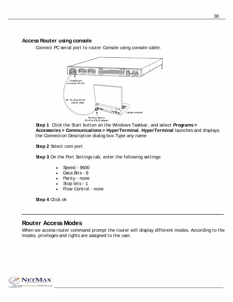
Access Router using console Connect PC serial port to router Console using console cable.
Step 1 Click the Start button on the Windows Taskbar, and select Programs > Accessories > Communications > HyperTerminal. HyperTerminal launches and displays the Connection Description dialog box.Type any name Step 2 Select com port
Step 3 On the Port Settings tab, enter the following settings:
• Speed - 9600 • Data Bits - 8 • Parity - none • Stop bits - 1 • Flow Control - none
Step 4 Click ok
________________________________________________________
Router Access Modes When we access router command prompt the router will display different modes. According to the modes, privileges and rights are assigned to the user.
__________________________________________________________________________

31
__________________________________________________________________________
User mode In this mode, we can display basic parameter and status of the router we can test connectivity and perform telnet to other devices. In this mode we are not configure to manage & configure router.
Privileged mode In this mode, we can display all information, configuration, perform administration task, debugging, testing and connectivity with other devices. We are not able to perform here configuration editing of the router. The command to enter in this mode is ‘enable’. We have to enter enable password or enable secret password to enter in this mode. Enable secret has more priority than enable password. If both passwords are configured then only enable secret will work.
Global configuration This mode is used for the configuration of global parameters in the router. Global parameters applied to the entire router. The command enter in this mode is ‘configure terminal’. For e.g: - router hostname or access list of router
Line configuration mode This mode is used to configure lines like console, vty and auxiliary. There are main types of line that are configured. (i) Console router(config)#line console 0 (ii) Auxiliary router(config)#line aux 0 (iii) Telnet or vty router(config)#line vty 0 4
Interface configuration mode This mode is used to configure router interfaces. For e.g:- Ethernet, Serial, BRI etc. Router(config)#interface <type> <number> e.g. Router(config)#interface serial 1
Routing configuration mode This mode is used to configure routing protocol like RIP, EIGRP, OSPF etc. Router(config)#router <protocol> [<option>]

32
Router(config)#router rip Router(config)#router eigrp 10
Configuring Passwords There are five types of password available in a router
(3) Auxiliary Password router#configure terminal router(config)#line Aux 0 router(config-line)#password <word> router(config-line)#login router(config-line)#exit
(4) Enable Password
router>enable router#configure terminal router(config)#enable password <word> router(config)#exit
Enab
Encr
TIP:
(1) Console Password router#configure terminal router(config)#line console 0 router(config-line)#password <word> router(config-line)#login router(config-line)#exit (2) Vty Password
router#configure terminal router(config)#line vty 0 4 router(config-line)#password <word> router(config-line)#login router(config-line)#exit
le Secret Password Enable Password is the clear text password. It is stored as clear text in configuration where as enable secret password is the encrypted password with MD5 (Media Digest 5) algorithm.
Router#configure terminal Router(config)#enable secret <word> Router(config)#exit
ypting all passwords All passwords other than enable secret password are clear text password. We can encrypt all passwords using level 7 algorithm. The command to encrypt all passwords are: Router#configure terminal Router(config)#service password-encryption
In CISCO router any configuration can be removed by using ‘no’ prefix to the same command.
__________________________________________________________________________

33
Managing Configuration There are two types of configurations present in a router
(1) Startup Configuration (2) Running Configuration Startup configuration is stored in the NVRAM. Startup configuration is used to save settings in a router. Startup configuration is loaded at the time of booting in to the Primary RAM. Running Configuration is present in the Primary RAM wherever we run a command for configuration, this command is written in the running configuration.
To display running-configuration Router#show running-configuration
To display startup configuration Router#show startup-configuration
To erase old configuration
To save configuration Router#copy running-config startup-config Or Router#write
To abort configuration Router#copy startup-config running-config
CISCO command line editing & shortcuts
Command line shortcuts Tab – to auto complete command ? – To take help Ctrl+P – to recall previous command Ctrl+N – next command Ctrl+Z – alternate to ‘end’ command Ctrl+C – to abort Q – to quit Ctrl+Shift+6 – to break connection
Command line editing shortcuts Ctrl+A – to move cursor at start of line Ctrl+E – to move cursor at end of line Ctrl+ B – to move cursor one character back Ctrl+F – to move cursor one character forward Ctrl+W – to delete word one by one word back Ctrl+D – to delete one character Ctrl+U – to delete one line Esc+B – to take cursor one word back
Configuring HostName Router#configure terminal Router#hostname <name>
________________________________________________________________
Configuration Interfaces Interfaces configuration is one of the most important part of the router configuration. By default, all interfaces of Cisco router are in disabled mode. We
__________________________________________________________________________

34
have to use different commands as our requirement to enable and configure the interface.
Configuring IP, Mask and Enabling the Interface Router#configure terminal Router(config)#interface <type> <no> Router(config-if)#ip address <ip> <mask> Router(config-if)#no shutdown Router(config-if)#exit
Interface Numbers Interface numbers start from 0 for each type of interface some routers will directly used interface number while other router will use slot no/port no addressing technique. Eth 0 Slot 1 Slot 0 Serial 0 Serial 1/0 Serial 0/0 Serial 1 Serial 1/1
__________________________________________________________________________
To configure Interface description Router#configure terminal Router(config)#interface <type> <no> Router(config-if)#description <line>
Configuring parameters on LAN interface Router#configure terminal Router(config)#interface <type> <no> R t ( fi if)#d l <h lf|f ll| t >
Configuring parameters on WAN interface Router#configure terminal Router(config)#interfac <type> <no> Router(config-if)#encapsulation <protocol> Router(config-if)#clock rate <value> Router(config-if)#end
To display interface status R t # h i t f (t h ll
Show interfaces command will display following parameters about an interface
Status Mac address IP address Subnet mask Hardware type / manufacturer Bandwidth Reliability Delay Load ( Tx load Rx load) Encapsulation ARP type (if applicable)
Keep alive Queuing strategy Input queue detail Output queue details Traffic rate (In packet per second,bit per second) Input packet details Output packet details Modem signals (wan interface only) M.T.U maximum transmission rate (mostly 1500 bytes)

35
Configuring sub interface Sub interface are required in different scenario. For e.g:- in Ethernet we need sub interface for Vlan communication and in frame relay we need sub interface for multipoint connectivity. Sub interface means creating a logical interface from physical interface.
Router#config ter Router(config)#interface <type> <no>.<subint no> Router(config-subif)# Router(config)#interface serial 0.2
Configuring secondary IP Router(config-if)#IP address 192.168.10.5 255.255.255.0 Router(config-if)#IP address 192.168.10.18 255.255.255.0 secondary
_______________________________________________________________
Managing Command Line History We can use CTRL+P & CTRL+N shortcuts to display command history. By default router will up to 10 commands. In the command line history, we can use following commands to edit this setting
To display commands present in history
Router#show history
To change history size Router#config terminal Router(config)#line console 0 Router(config-if)#history size <value>
Configuring Banners Banners are just a message that can appear at different prompts according to the type. Different banners are: Message of the day (motd)-This banner appear at every access method
Login-Appear before login prompt
Exec- Appear after we enter to the execution mode
Incoming-Appear for incoming connections
__________________________________________________________________________
Syntax:- Router#config terminal Router(config)#banner <type> <delim. char>
Text Massage <delimation char>
Router(config)#
Example:- Router#config terminal Router(config)#banner motd $ This router is distribution 3600 router connected to Reliance $

36
Logging configuration Router generates the log message, which has stored in the router internal buffer and also displayed on the console.
Synchronous Logging on console Router#config terminal Router(config)#line console 0 Router(config)#logging synchronous Router(config)#exit
To send log messages to sys log server Router#config ter Router(config)#logging <IP address> Router(config)#exit
Download Syslog Server Software from internet & install it on PC to store syslog messages.
Configuring Router Clock We can configure router clock with the help of two methods.
(1) Configure clock locally (2) Using NTP server (Network Time Protocol) Router does not have battery to save the clock setting. So that clock will reset to
the default on reboot. In new routers clock battery will be available for time keeping.
__________________________________________________________________________
To display clock Router#show clock
To configure clock Router#clock set hh:mm:ss day month year
To configure clock from NTP server Router#config terminal Router(config)#ntp server <IP address> Router(config)#exit
Use “C:\>ping pool.ntp.org” To get ntp server ip from internet
Status message of Interfaces When we use “Show Interfaces” command on router. The first two lines will display the status message. It will display one of the following four messages.
Interface is administratively down, line protocol is down.
This message means that the interface is shutdown by the administrator using “shutdown” command. We can change this status with help of “no shutdown” command.
Interface is up, line protocol is up.

37
This message will appear when everything working fine and interface is able to communicate with other devices. In case of Ethernet, this message will display when interface is connected and enabled. In case of serial, this message will display when end to end connectivity is established.
Interface is down, line protocol is down In case of serial, this message will appear due to loss in connectivity with modem.
Interface is up, line protocol is down This message will appear due to the encapsulation failure. In case of Ethernet, this message may appear when interface is not connected properly. In case of serial, this message may appear due connectivity problem with far end router.
Setup Mode
The router will enter in setup mode if there is no configuration is present in NVRAM. The router will display following message
“Would you like to enter in initial configuration dialog [ y / n ]: “ There are two types of setup modes:
• Basic setup mode • Extended setup mode
In basic mode only one interface is configured which will be used for telnet or web access connectivity. In extended mode all interfaces are configured. At the end we can save configuration changes or discard changes
Telnet access Telnet is a virtual port through which we can access router command line using interfaces
__________________________________________________________________________
Switch Router
PC

38
__________________________________________________________________________
To accept telnet connection we have to configure following options on router: Configure IP on interface Configure VTY, enable secret password On client PC test connectivity with router & use command ‘telnet <router_ip>’
SSH access to Router or Switch
There are four steps required to enable SSH support on an IOS router:
1. Configure the hostname, domain name command. 2. Generate the SSH key to be used. 3. Enable SSH transport support for the virtual type terminal (vtys). 4. Enable aaa new model 5.
SDM access to Router or Switch 1. Install SDM software on PC 2. Install java run time environment 3. install latest browser 4. enable http server in router (config)# ip http server 5. Configure IP address on router and establish connectivity with PC 6. Open browser and type http://<ip of router>/ 7. Enter enable secret password if configured.

39
Advanced router administration
Router Booting Sources
A router can boot from various sources. By default, it will boot from the flash memory and we can control the sequence with the help of configuration system or commands. A router can boot from following sources: -
(1) First file in flash (2) Specific file in flash (3) Incomplete IOS (4) TFTP Server (5) Rom Monitor (from Bios) The first to control boot sequence using configuration system register. We can modify
configuration register value with the help of “config-register” command in global configuration mode. We can also modify register value from ROM monitor mode.
Configuration Register Configuration Register is 16-bit value, which is stored in the NVRAM. At the time of booting
the Bootstrap Loader reads the value of configuration Register and according to the value it configure its booting behavior.
0x2102 (IOS with Config) With this value the router will boot from first file present in the flash memory. This is the default value of configuration register. After loading IOS the router will also load startup-config into running-config.
0x2101 (Incomplete IOS with Config) The router will boot from incomplete IOS and then load the startup-config.
0x2100 (Rom Monitor) With this router will not boot, but enters in the Rom Monitor mode.
0x2142 (IOS without Config) The router will boot from first file in flash. But bypass the startup configuration
0x2141 (Incomplete IOS without Config) The router will boot from Incomplete IOS but bypass the startup-config.
To change Config-Register from global mode Router#configure terminal Router(config)#config-register <value> Router(config)#exit
Note: - this is the only value, which is configured in the configuration mode and does not need to be saved.
__________________________________________________________________________

40
To change Config-Register using Rom Monitor Steps: - (1) Power on the router (2) Press “ctrl+break” from console with in 60 sec. (3) The router will enter to the Rom Monitor. Type following commands
Rommon 1> confreg <value> Rommon 2> i
Note: - in 2500 series router “o/r” command should be used in place of “confreg” command.
Boot System commands Boot system command is the second method to control sequence of router. These commands will be executed only when configuration register is set to 0x2102. Boot system commands are executed in global configuration mode. These commands are executed in the same sequence they are applied to the router. If one boot system command is successful then next boot system command is not executed in the router.
To boot router from specific file in flash Router(config)#boot system flash <file name> To boot router from TFTP server/network Router(config)#boot system tftp <file name> <IP address>
To boot from first file in flash Router(config)#boot system flash To boot from incomplete IOS Router(config)#boot system rom
Using TFTP server in CISCO TFTP server is modified form of FTP. It is used to transfer file without performing
authentication. TFTP has only home directory, in which subdirectories are not allowed. Directory browsing is not allowed in the home directory. TFTP server
TFTP is the udp-based protocol, which works on port no 69. TFTP has following features in comparison to the FTP.
• Only get file and put file service is available. • Authentication is not supported. • Home directory may not have subdirectories • Directory browsing is not allowed
Installation and Configuration of TFTP server In windows system, we have to execute following steps to use the pc as TFTP server.
• Download TFTP server software from Internet.
__________________________________________________________________________

41
• Install the TFTP server software on pc. • If software is not installed as the service then software should be running on
screen. • Configure home directory of server or use default.
Functions to be perform with the help of TFTP server • To boot router from TFTP server • Backup IOS and configuration • Restore IOS and configuration • Upgrade IOS
To boot from TFTP server
• Run the tftp server s/w on pc. And copy IOS image file in the Home directory of tftp server.
• Test connectivity between router and tftp server. • On router use following commands:-
Router#conf ter Router(config)#boot system tftp c1700-1s-mz.122.3.bin 10.0.0.18 Router(config)#exit Router#copy runn start
Reload the device. Make sure that configuration register set as 0x2102. To backup IOS
• Test connectivity and make sure TFTP server is running. • Type command: -
Router#show flash (note the IOS filename) Router#copy flash TFTP
Source filename = ? Destination filename=? IP of TFTP server=?
To backup Configuration • Test connectivity and make sure TFTP server is running. • Type commands: -
__________________________________________________________________________
Router#copy running-config tftp OR Router#copy startup-config tftp Remote IP: ________ Destination Filename: ________

42
__________________________________________________________________________
To restore Configuration
Test connectivity and make sure TFTP server is running. Make sure configuration file is present in home directory and note the filename. Type commands: -
Router#copy tftp running-config Remote IP: __________ Source Filename: ___________ Destination Filename[running-config]: _ Press enter here Restore/Upgrade IOS
There are four different conditions in which we can restore/upgrade IOS. Case 1: old IOS is present and flash is in read/write mode.
• Copy IOS image in tftp server’s home directory. • Test connectivity and make sure tftp server is running. • On router use commands: -
Router# copy tftp flash Source file: - Destination file: - IP address: - Erase Flash [y/n]:
Case2: Old IOS is present but flash is in read only mode.
In this case, we have to set config-register to 0x2101 to boot the router from incomplete IOS. After booting the flash will be read/write mode. Now use same command as in condition case 1. When IOS loading is complete reset config-register to 0x2102.
Case3: old IOS is not present but incomplete IOS is present in bios. The router will automatically boot from incomplete IOS. And we have to execute same commands as in case1 and case2.
Case4: Complete IOS and incomplete IOS is not present in router. There are two methods to load IOS with the help of Rom Monitor mode.
Method1: Loading IOS using xmodem
In this case we have to use xmodem command and the IOS will be loaded with the help of console cable. Tftp is not required in this case.
Enter to the Rom Monitor and type following command. Rom Mon 1>xmodem <filename>

43
When router display a message “ Ready to receive file” then click on HyperTerminal then Transfer>> Send file>> use browse to select file>> select protocol xmodem>> send.
Method2: In this case we have to use tftp server in Rom Monitor. Connect the pc tftp server make sure tftp is running and IOS image present in the home directory.
Enter to the Rom Monitor mode and type following command. Rom Mon>IP_ADDRESS=10.0.0.2 Rom Mon> TFTP_SERVER=10.0.0.1 Rom Mon> TFTP_FILE=<filename> Rom Mon> DEFAULT_GATEWAY=10.0.0.1 Rom Mon> IP_SUBNET_MASK=255.0.0.0 Rom Mon> tftpdnld When IOS transfer is completed then type command. Rom Mon>boot
To view source from which router boots.
Router#show version
________________________________________________________________
Resolving Host Names In router, we can communicate with the help of IP address as well as host name and domain name. There are two methods to resolve hostname into IP address.
Using local hostname database
We can use local hostname database by using IP host command. We can use this command with following syntax: -
To create local hostname database Router(config)#IP host <name> <IP address>
To display hosts Router#show hosts
Using a DNS server
We can configure router to send DNS queries to DNS server. The DNS server will resolve hostname and then pc or router will try to communicate with destination. We can create maximum 6 IP.
Router#config terminal Router(config)#IP name-server <IP> [<IP2>] Router(config)#IP name-server 202.56.230.6 Router(config)#exit
__________________________________________________________________________

44
____________________________________________________________________________________
Managing Telnet connection Our router is able to telnet other devices as well as other devices can also perform telnet to our router.
To allow Telnet access to router For this purpose we have to configure IP address, vty password and enable
secret password. IP must exist between client and router. When router will be able to perform telnet access. On telnet client we have to use following command: - Router#Telnet <IP of router>
To display connected users Router#show users
To disconnect a user Router#clear line <no>
To telnet a device from router Router#telnet <IP>
To exit from telnet session Router#exit
TIP: If we want to allow telnet router without password then on the VTY type command “No Login”.
_____________________________________________________________________________
Cisco Discovery Protocol This protocol is by default enabled in Cisco devices. It will send periodic update after every one minute on all interfaces. The neighbors will receive this information and store in the CDP neighborship table. CDP is helpful in troubleshooting or to create documentation of CDP. We can obtain following information about neighbor automatically.
(1) Hostname (2) Device type (3) Model/Platform (4) IOS version (5) Local connected interface (6) Remote device connected interface (7) Entry IP address etc.
__________________________________________________________________________

45
__________________________________________________________________________
Display CDP status Router#sh cdp
To display CDP enabled interfaces Router#sh cdp interface
To display CDP neighbors Router#sh cdp neighbor Or Router#sh cdp neighbor detail
To disable CDP from device Router#conf ter Router(config)#no cdp run
To disable CDP on particular interface Router#conf ter Router(config)#int <type> <no.> Router(config-if)#no cdp enable Router(cobfig-if)#exit
To change CDP timers Router#conf ter Router(config)#cdp timer <value> (by default 60 sec) Router(config)#cdp holdtime <value> (by default 180 sec) (Value in seconds)

46
TCP/IP MODEL TCP/IP is the most popular protocol stack, which consist of large no of protocol. According to the OSI model TCP/IP consist of only four layers. TCP/IP model is modified form of DOD (Department of Defense) model.
Application Layer This layer contains a large no. of protocols. Each protocol is designed to act as server &
client. Some of protocol will need connection oriented. TCP and others may need connection less UDP for data transfer. Application layer use port no.s to identity each application at Transport layer. This layer performs most of functions, which are specified by the Application, Presentation, and Session layer of OSI model.
Transport Layer Two protocols are available on Transport layer Transmission Control Protocol User Datagram Protocol
__________________________________________________________________________

47
Transmission Control Protocol: TCP performs connection-oriented communication. Its responsibilities are: - Error Checking Acknowledgement Sequencing Flow Control Windowing
• Source Port and Destination Port fields together identify the two local end points of the particular connection. A port plus its hosts’ IP address forms a unique end point. Ports are used to communicate with the upper layer and distinguish different application sessions on the host.
• The Sequence Number and Acknowledgment Number fields specify bytes in the byte stream. The sequence number is used for segment differentiation and is useful for reordering or retransmitting lost segments. The Acknowledgment number is set to the next segment expected.
• Data offset or TCP header length indicates how many 4-byte words are contained in the TCP header.
• The Window field indicates how many bytes can be transmitted before an acknowledgment is received.
• The Checksum field is used to provide extra reliability and security to the TCP segment.
• The actual user data are included after the end of the header.
__________________________________________________________________________

48
User Datagram Protocol UDP is considered to be a connectionless protocol. It leaves reliability to be handled by the application layer. All it cares about is fast transmission. UDP header is responsible for error checking and identifying applications using port numbers.
Internet Layer The main function of Internet layer is routing and providing a single network interface to the upper layers protocols. Upper or lower protocols have not any functions relating to routing. To prevent this, IP provides one single network interface for the upper layer protocols. After that it is the job of IP and the various Network Access protocols to get along and work together. The main protocols are used in Internet layer:-
1) Internet Protocol (IP) 2) Internet Control Message Protocol (ICMP) 3) Address Resolution Protocol (ARP) 4) Reverse Address Resolution Protocol (RARP) 5) Proxy ARP
Internet Protocol This protocol works at internet layer. It is responsible for logical addressing, defining type of service and fragmentation.
__________________________________________________________________________

49
• Source Port and Destination Port fields together identify the two local end points of the particular connection. A port plus its hosts IP address forms a unique end point. Ports are used to communicate with the upper layer and distinguish different application sessions on the host.
• The Sequence Number and Acknowledgment Number fields specify bytes in the byte stream. The sequence number is used for segment differentiation and is useful for reordering or retransmitting lost segments. The Acknowledgment number is set to the next segment expected.
• Data offset or TCP header length indicates how many 4-byte words are contained in the TCP header.
• Window indicates how many bytes can be transmitted before an acknowledgment is received.
• Checksum is used to provide extra reliability and security to the TCP segment. • User data represents the actual data which are always included at end of the
header.
__________________________________________________________________________

50
__________________________________________________________________________
IP Subnetting In TCP/IP by default three sizes of networks are available: - (1) Class A -224 PC -> 16777216 (2) Class B - 216 PC-> 65536 (3) Class C – 28 PC -> 256
In subneting, we will divide class A,B & C network into small size sub networks. This procedure is called subneting. Subneting is performed with the help of subnet mask. There are two types of subneting that we performed: - (1) FLSM Fixed Length Subnet Mask (2) VLSM Variable Length Subnet Mask
Why to Subnet (i) Default Class Network provide us large no. of PCs in comparison to the requirement of PCs in the network. (ii) It is practical never possible to create a class A or class B sized network. To reduce the broadcast of network, we have to perform LAN segmentation of routers. In each sub network, we need different network addresses.
How to Subnet? In this formula, we will first modify our requirement according to the no. of subnet possible then we calculate new subnet mask and create IP range.
Example 1 Class = C No. of subnet =5 Step1 No. of subnet possible is 2,4,8,16,32…… Class= C No. of subnets= 8 Step 2 Calculate key value 2? = No. of subnets 2? = 8 23= 8 Step 3 Calculate new subnet mask In class C

51
__________________________________________________________________________
Net id Host id 24+key 8-key 24+3 8-3 27 5 11111111.11111111.11111111.11100000 255. 255. 255. 224 We add this address to make subnet mask Step 4 Range No. of Pc/Subnet= Total Pc/ No. of Subnet = 256/8 =32 In Class C x.x.x.0 – x.x.x.31 (1)- (30) x.x.x.32- x.x.x.63 64- 95 96- 127 128- 159 160- 191 192- 223 x.x.x.224-x.x.x.255 The first IP of each subnet will be subnet id and last IP will be sub network broadcast address. Example 2 Class= C No. of subnet= 10 Step 1 No. of subnet= 16 Step 2 24= 16 Step 3 Net id Host id 24+4 8-4 11111111.11111111.11111111.11110000
Subneting method 2
52
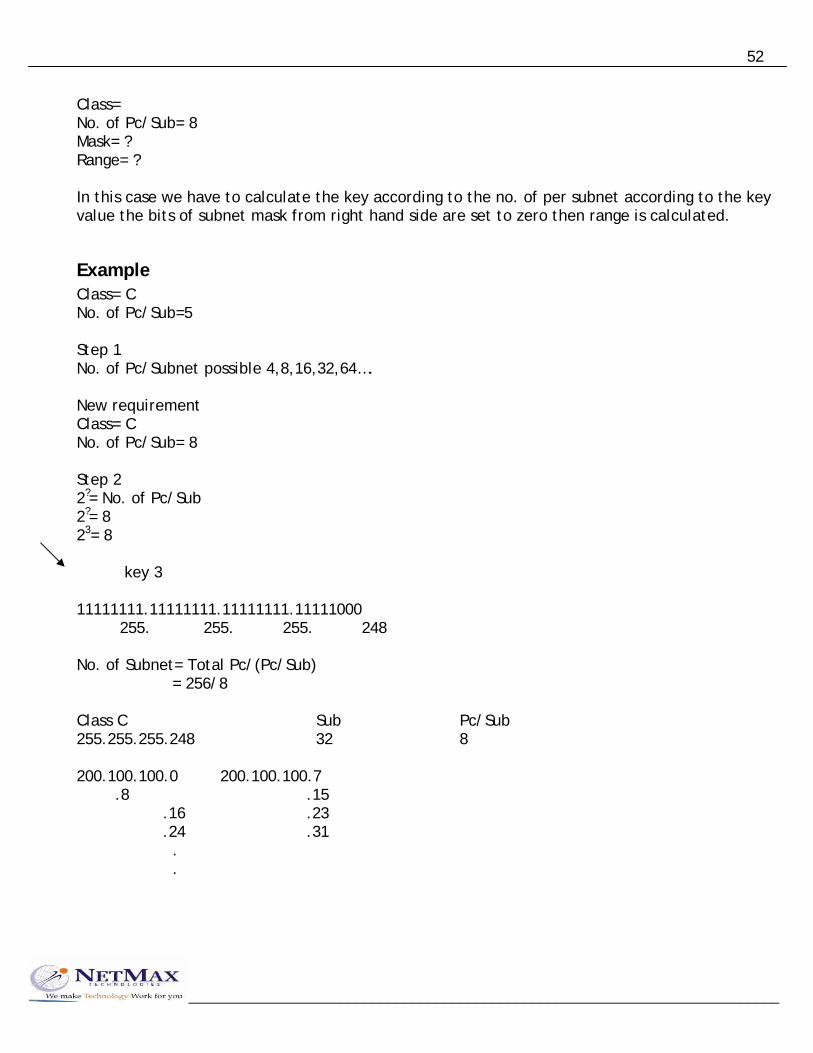
Class= No. of Pc/Sub= 8 Mask= ? Range= ? In this case we have to calculate the key according to the no. of per subnet according to the key value the bits of subnet mask from right hand side are set to zero then range is calculated.
Example Class= C No. of Pc/Sub=5 Step 1 No. of Pc/Subnet possible 4,8,16,32,64…. New requirement Class= C No. of Pc/Sub= 8 Step 2 2?= No. of Pc/Sub 2?= 8 23= 8 key 3 11111111.11111111.11111111.11111000 255. 255. 255. 248 No. of Subnet= Total Pc/(Pc/Sub) = 256/8 Class C Sub Pc/Sub 255.255.255.248 32 8 200.100.100.0 200.100.100.7 .8 .15 .16 .23 .24 .31 . .
__________________________________________________________________________

53
__________________________________________________________________________
Example 2 Class C No. of Pc/Sub=50 Step 1 Class= C No. of Pc/Sub= 64 Step 2 26= 64 11111111.11111111.11111111.11000000 255. 255. 255. 192 No. of subnet= 256/64= 4 Class C Sub Pc/Sub 255.255.255.192 4 64
Method 3 No. of Pc/Sub= 50 New req. No. of Pc/Sub= 64 No. of Subnet= 256/64= 4 Class= C No. of Sub= 4 22= 4 24+2 8-2 11111111.11111111.11111111.11000000 255. 255. 255. 192
Zero Subnet According to the rules of IP Addressing the first subnet and last subnet is not useable due to routing problem. In new Cisco router a command is present in default configuration. With this command, we are able to use first and last Subnet after Subneting. Command is Router#config ter Router(config)#ip subnet-zero

54
Router(config)#exit Example: - Check whether an address is valid IP, N/w address or Broadcast address. If IP is valid then calculate its N/w & Broadcast address. 200.100.100.197 255.255.255.240 28 4 200.100.100.197 200.100.100.1100 0101 Valid IP 200.100.100.192 200.100.100.1100 0000 Network address 200.100.100.207 200.100.100.1100 1111 Broadcast address Example: - Class= B No. of subnet= 64 26= 64 11111111.11111111.11111111.11000000 255. 255. 255. 192 No. of Pc/Sub= 65536/64= 1024 150.20.0.0 – 150.20.3.255 150.20.4.0 – 150.20.7.255 150.20.8.0 – 150.20.11.255
Prefix Notation of representing IP Address IP address can be written as IP & Mask as well as IP/Prefix. 200.100.100.18 255.255.255.248 200.100.100.18/29 170.20.6.6 255.255.255.224.0 170.20.6.6/19 This method is representing IP address also called CIDR (Classless Inter Domain Routing) notation.
__________________________________________________________________________

55
No Subneting 200.100.8.X 200.100.1.X 200.100.7.X 200.100.9.X 200.100.4.X 200.100.6.X 200.100.5.X 200.100.3.X 200.100.2.X
FLSM 200.100.1.112-127/28 200.100.1.128-143/28 200.100.1.95-111/28 200.100.1.48-63/28 200.100.1.80-95/28 200.100.1.64-79/28 200.100.1.32-47/28 200.100.0-15/28 200.100.1.16-31/28
Remaining Subnet 144 – 159 160 – 175 176 – 191
__________________________________________________________________________

56
192 – 207 208 – 223 224 – 239 240 – 255
Problem with FLSM In FLSM, we have to create subnet of equal size. All N/w will be allotted constant size subnet instead of their IP addresses requirement. Due to this a N/w may be allotted more than required IP address and less than required IP addresses.
VLSM /25 /26 /27 /28 /29 255.255.255.128 255.255.255.192 255.255.255.224 255.255.255.240 255.255.255.248
Sub Pc/Sub Sub Pc/Sub Sub Pc/Sub Sub Pc/Sub Sub Pc/Sub 2 128 4 64 8 32 16 16 32 8
__________________________________________________________________________
0 – 127 0 – 63 0 – 31 0 – 15 0 – 7 128 – 255 64 – 127 32 – 63 16 – 31 8 – 15 128 – 191 64 – 95 32 – 47 16 – 23 192 – 255 96 – 127 48 – 63 24 - 31 64 –79 80 – 95 96 – 111 /30 255.255.255.252
Sub Pc/Sub 64 4 0 – 3 4 – 7 8 – 11 20 64 12 – 15 32-63/30 64-95/27

57
2 IP 2 0-3/30 4-7/30 2 2 8-11/30 12-15/30 5 16-23/29 10 50 96-111/28 128-191/26 Remaining 24 – 31 112 – 127 If we are using VLSM and Dynamic Routing then routing be compatible to VLSM. This will happen only if Subnet masks are also sends in the routing updates.
Super Netting Combining small N/w to create a large size N/w is called Super Network. Super netting is mostly used to define route summarizations in routing tables. It is not used for the implementation of large network. 170.10.0.0 170.00001010.00000000.00000000 170.11.0.0 170.00001011.00000000.00000000
__________________________________________________________________________

58
IP Routing When we want to connect two or more networks using different n/w addresses then we have to use IP Routing technique. The router will be used to perform routing between the networks. A router will perform following functions for routing.
• Path determination • Packet forwarding
(1) Path determination
The process of obtaining path in routing table is called path determination. There are three different methods to which router can learn path.
• Automatic detection of directly connected n/w. • Static & Default routing • Dynamic routing
(2) Packet forwarding
It is a process that is by default enable in router. The router will perform packet forwarding only if route is available in the routing table.
Routing Process • The pc has a packet in which destination address is not same as the local n/w address. • The pc will send an ARP request for default gateway. The router will reply to the ARP
address and inform its Mac address to pc. • The pc will encapsulate data, in which source IP is pc itself, destination IP is server, source
Mac is pc’s LAN interface and destination Mac is router’s LAN interface.
R1
__________________________________________________________________________
10.0.0.1 PC1 10.0.0.6 172.16.0.5
S. MAC D. MAC PC1 R1 D. IP 172.16.0.5 S. IP 10.0.0.6

59
__________________________________________________________________________
The router will receive the frame, store it into the buffer. When obtain packet from the frame then forward data according to the destination IP of packet. The router will obtain a route from routing table according to which next hop IP and interface is selected (iv) According to the next hop, the packet will encapsulated with new frame and data is send to the output queue of the interface.
Static Routing In this routing, we have to use IP route commands through which we can specify routes for different networks. The administrator will analyze whole internetwork topology and then specify the route for each n/w that is not directly connected to the router.
Steps to perform static routing (1) Create a list of all n/w present in internetwork. (2) Remove the n/w address from list, which is directly connected to n/w. (3) Specify each route for each routing n/w by using IP route command. Router(config)#ip route <destination n/w> <mask> <next hop ip> Next hop IP it is the IP address of neighbor router that is directly connected our router.
Static Routing Example: - Router#conf ter Router(config)#ip route 10.0.0.0 255.0.0.0 192.168.10.2
Advantages of static routing (1) Fast and efficient. (2) More control over selected path. (3) Less overhead for router. (4) Bandwidth of interfaces is not consumed in routing updates.
Disadvantages of static routing (1) More overheads on administrator. (2) Load balancing is not easily possible. (3) In case of topology change routing table has to be change manually.

60
__________________________________________________________________________
Steps to perform static routing Create a list of all the networks present in internetwork Specify route for each network unknown by router with following command Router(config)#ip route <desination network> < Subnet mask > < Next Hop IP> Next hop IP is the neighbor router interface which is directly connected to our router.
Alternate command to specify static route Static route can also specify in following syntax: - Old Router(config)#ip route 172.16.0.0 255.255.0.0 172.25.0.2 Or Router(config)#ip route 172.16.0.0 255.255.0.0 serial 0
Backup route or loading static route If more than one path are available from our router to destination then we can specify one route as primary and other route as backup route. Administrator Distance is used to specify one route as primary and other route as backup. Router will select lower AD route to forward the traffic. By default static route has AD value of 1. With backup path, we will specify higher AD so that this route will be used if primary route is unavailable.
Protocols AD Directly Connected 0 Static 1 BGP 20 EIGRP 90 IGRP 100 OSPF 110 RIP 120
Syntax: - To set backup path
Router(config)#ip route <dest. n/w> <mask> <next hop> <AD> Or <exit interface>
Example: - Router#conf ter Router(config)#ip route 150.10.0.0 255.255.0.0 150.20.0.5

61
Router(config)#ip route 150.10.0.0 25.255.0.0 160.20.1.1 8 (below 20) Router(config)#exit
Default Routing Default routing means a route for any n/w. these routes are specify with the help of following syntax: - Router(config)#ip route 0.0.0.0 0.0.0.0 <next hop> Or <exit interface> This type of routing is used in following scenario.
Scenario 1: - Stub network A n/w which has only one exit interface is called stub network.
__________________________________________________________________________
R
If there is one next hop then we can use default routing.
Scenario 2 Internet connectivity On Internet, million of n/ws are present. So we have to specify default routing on our router. Default route is also called gateway of last resort. This route will be used when no other routing protocol is available.
ISP

62
200.100.100.11 172.16.0.5
__________________________________________________________________________
10.0.0.0
R1 R2
Router(config)#ip route 10.0.0.0 255.0.0.0 172.16.0.5 Router(config)#ip route 0.0.0.0 0.0.0.0 200.100.100.11
To display routing table Router#sh ip route
To display static routes only Router#sh ip route static
To display connected n/ws only Router#sh ip route connected S 192.168.10.0/28 [1/0] via 172.16.0.5
_____________________________________________________________________
Dynamic Routing In dynamic routing, we will enable a routing protocol on router. This protocol will send its routing information to the neighbor router. This protocol will send its routing information to the neighbor router. The neighbors will analyze the information and write new routes to the routing table. The routers will pass routing information receive from one router to other router also. If there are more than one path available then routes are compared and best path is selected. Some examples of dynamic protocol are: - RIP, IGRP, EIGRP, OSPF
Types of Dynamic Routing Protocols According to the working there are two types of Dynamic Routing Protocols.
(1) Distance Vector (2) Link State
According to the type of area in which protocol is used there are two types of protocol: - (1) Interior Routing Protocol (2) Exterior Routing Protocol

63
Autonomous system Autonomous system is the group of contiguous routers and n/w, which will share their routing information directly with each other. If all routers are in single domain and they share their information directly with each other then the size of routing updates will depend on the no. of n/w present in the Internetwork. Update for each n/w may take 150 – 200 bytes information. For example: - if there are 1000 n/ws then size of update will be 200*1000 = 200000 bytes The routing information is send periodically so it may consume a large amount of bandwidth in our n/w. AS 500
AS 400AS 200
Interior Routing
Exterior Routing Border Routing
Domain
Protocols Interior Routing Exterior Routing RIP BGP IGRP EXEIGRP EIGRP OSPF
Distance Vector Routing The Routing, which is based on two parameters, that is distance and direction is called Distance Vector Routing. The example of Distance Vector Routing is RIP & IGRP.
__________________________________________________________________________

64
__________________________________________________________________________
Operation: - (1) Each Router will send its directly connected information to the neighbor router. This information is send periodically to the neighbors. (2) The neighbor will receive routing updates and process the route according to following conditions: - (i) If update of a new n/w is received then this information is stored in routing table. (ii) If update of a route is received which is already present in routing table then route will be refresh that is route times is reset to zero. (iii) If update is received for a route with lower metric then the route, which is already present in our routing table. The router will discard old route and write the new route in the routing table. (iv) If update is received with higher metric then the route that is already present in routing table, in this case the new update will be discard. (3) A timer is associated with each route. The router will forward routing information on all interfaces and entire routing table is send to the neighbor. There are three types of timers associated with a route. (i) Route update timer It is the time after which the router will send periodic update to the neighbor. (ii) Route invalid timer It is the time after which the route is declared invalid, if there are no updates for the route. Invalid route are not forwarded to neighbor routers but it is still used to forward the traffic. (iii) Route flush timer It is the time after which route is removed from the routing table, if there are no updates about the router.
Metric of Dynamic Routing Metric are the measuring unit to calculate the distance of destination n/w. A protocol may use a one or more than one at a time to calculate the distance. Different types of metric are: - (1) Hop Count (2) Band Width (3) Load (4) Reliability (5) Delay (6) MTU

65
__________________________________________________________________________
Hop Count:It is the no. of Hops (Routers) a packet has to travel for a destination n/w.
Bandwidth : Bandwidth is the speed of link & path with higher bandwidth is preferred to send data.
Load : Load is the amount of traffic present in the interface. Paths with lower load and high throughput
is used to send data.
Reliability : Reliability is up time of interface over a period of time.
Delay : Delay is the time period b/w a packet is sent and received by the destination. MTU : Maximum Transmission Unit It is the maximum size of packet that can be sent in a frame mostly MTU is set to 1500.
Problems of Distance Vector There are two main problems of distance vector routing
(1) Bandwidth Consumption (2) Routing Loops
Bandwidth Consumption The problem of accessive bandwidth consumption is solved out with the help of autonomous system. It exchanges b/w different routers. We can also perform route summarization to reduce the traffic.
Routing Loops It may occur between adjacent routers due to wrong routing information. Distance Vector routing is also called routing by Rumor. Due to this the packet may enter in the loop condition until their TTL is expired.
Method to solve routing loops There are five different methods to solve or reduce the problem of routing loop. (1) Maximum Hop Count (2) Flash Updates/Triggered Updates (3) Split Horizon (4) Poison Reverse (5) Hold Down

66
__________________________________________________________________________
Maximum Hop Count This method limits the maximum no. of hops a packet can travel. This method does not solve loop problem. But it reduce the loop size in the n/w. Due to this method the end to end size of a n/w is also limited.
Flash Updates/Triggered Updates In this method a partial update is send to the all neighbors as soon as there is topology change. The router, which receives flash updates, will also send the flash updates to the neighbor routers.
Split Horizon Split Horizon states a route that update receive from an interface can not be send back to same interface.
Poison Reverse This method is the combination of split Horizon and Flash updates. It implements the rule that information received from the interface can not be sent back to the interface and in case of topology change flash updates will be send to the neighbor.
Hold Down If a route changes frequently then the route is declared in Hold Down state and no updates are received until the Hold Down timer expires.
Routing Information Protocol Features of RIP: -
• Distance Vector • Open standard • Broadcast Updates
(255.255.255.255) • Metric - Hop Count
Timers Update 30 sec Invalid 180 sec Hold 180 sec Flush 240 sec * Loop Control Split Horizon Triggered Updates Maximum Hop Count Hold Down * Maximum Hop Count 15 * Administrative Distance 120 * Equal Path Cost Load Balancing * Maximum Load path 6

67
Default 4 * Does not support VLSM * Does not support Autonomous system
Configuring RIP Router#conf ter Router(config)#router rip Router(config-router)#network <own net address> Router(config-router)#network <own net address> -------------- -------------- Router(config-router)#exit
172.16.0.6 10.0.0.1 172.16.0.5 175.2.1.1 200.100.100.12
R1
Router(config-router)#network 10.0.0.0 Router(config-router)#network 172.16.0.0 Router(config-router)#network 200.100.100.0 175.2.0.0 via 172.16.0.6
Display RIP Routers Router#sh ip route rip R 192.168.75.0/24 [120/5] via 172.30.0.2 00:00:25 serial 1/0
__________________________________________________________________________
RIP Dest. n/w mask AD Metric Next Hop Timer own Interface

68
__________________________________________________________________________
RIP advanced configuration
Passive Interfaces An interface, which is not able to send routing updates but able to receive routing update only is called Passive Interface. We can declare an interface as passive with following commands: - Router#conf ter Router(config)#router rip Router(config-router)#Passive-interface <type> <no> Router(config-router)#exit
To change Administrative Distance Router(config)#router rip Router(config-router)#distance <value> Router(config-router)#exit 95 or 100
To configure Load Balance RIP is able to perform equal path cost Load Balancing. If multiple paths are available with equal Hop Count for the destination then RIP will balance load equally on all paths. Load Balancing is enabled by default 4 paths. We can change the no. of paths. It can use simultaneously by following command: - Router(config)#router rip Router(config-router)#maximum-path <1-6>
To display RIP parameters Router#sh ip protocol Or Router#sh ip protocol RIP
This command display following parameters: - (i) RIP Timers (ii) RIP Version (iii) Route filtering (iv) Route redistribution (v) Interfaces on which update send (vi) And receive (vii) Advertise n/w (viii) Passive interface (ix) Neighbor RIP (x) Routing information sources (xi) Administrative Distance

69
__________________________________________________________________________
RIP version 2 RIP version 2 supports following new features: - (1) Support VLSM (send mask in updates) (2) Multicast updates using address 224.0.0.9 (3) Support authentication
Commands to enable RIP version 2 We have to change RIP version 1 to RIP version 2. Rest all communication will remain same in RIP version 2.
Router(config)#Router RIP Router(config-router)#version 2 Router(config-router)#exit
RIP Debugging
To debug RIP routing Router#debug ip rip
To disable debug routing Router#no debug ip rip Or Router#no debug all Or Router#undebug all
_____________________________________________________________________
Interior Gateway Routing Protocol Features: - * Cisco proprietary * Distance vector * Timers Update 90 sec Invalid 270 sec Hold time 280 sec Flush 630 sec * Loop control All methods * Max hop count 100 upto 255

70
__________________________________________________________________________
* Metric (24 bit composite) Bandwidth (default) Delay (default) Load Reliability MTU * Broadcast updates to address 255.255.255.255 * Unequal path cost load balancing * Automatic route summarization * Support AS * Does not support VLSM
Configuring IGRP Router(config)#router igrp <as no>(1 – 65535) Router(config-router)#network <net address> Router(config-router)#network <net address> Router(config-router)#exit
_____________________________________________________________________
Link State Routing This type of routing is based on link state. Its working is explain as under (1) Each router will send Hello packets to all neighbors using all interfaces. (2) The router from which Hello reply receive are stored in the neighborship table. Hello packets are send periodically to maintain the neighbor table. (3) The router will send link state information to the all neighbors. Link state information from one neighbor is also forwarded to other neighbor. (4) Each router will maintain its link state database created from link state advertisement received from different routers. (5) The router will use best path algorithm to store the path in routing table.
Problems of Link State Routing The main problems of link state routing are: - (1) High bandwidth consumption. (2) More hardware resources required that is processor and memory (RAM)

71
_____________________________________________________________________
Enhanced Interior Gateway Routing Protocol Features: -
* Cisco proprietary * Hybrid protocol Link State Distance Vector * Multicast Updates using Address 224.0.0.10 * Support AS * Support VLSM * Automatic Route Summarization * Unequal path cost load balancing
* Metric (32 bit composite) Bandwidth Delay Load Reliability MTU * Neighbor Recovery * Partial updates * Triggered updates * Backup Route * Multi Protocol Routing
EIGRP Protocols & Modules Protocol depended module This module is used to perform multi protocol routing that is the router will maintain 3 routing table for TCP/IP, IPX/SPX and Appletalk. It will analyze the update packet and send to the corresponding routing table. Reliable Transport Protocol RTP is used to exchange routing updates with neighbor routers. It will also maintain neighbor relationship with the help of Hello packet. RTP has following features: - (1) Multicast updates (224.0.0.10) (2) Neighbor recovery: If neighbor stops responding to the Hello packets then RTP will send 16 unicast Hello packet for that neighbor. (3) Partial updates (4) No updates are send if there is no topology change. Due to this feature it is also called quiet protocol. Diffusing Update Algorithm (DUAL)
DUAL is responsible for calculating best path from the topology table. Dual has following features: - * Backup Path * VLSM * Route queries to neighbor for unknown n/w.
__________________________________________________________________________

72
Configuring EIGRP Basic Configuration
Router(config)#router eigrp <as no> Router(config-router)#network <net addr.> Router(config-router)#network <net addr.> Router(config-router)#exit
Configuring Bandwidth on Interface for EIGRP By default the router will detect maximum speed of interface and use this value as the bandwidth metric forEIGRP. But it may be possible that the interfaces and working at its maximum speed then we have to configure bandwidth on inte rface, so that EIGRP is able to calculate correct method.
Router(config)#interface <type> <no> Router(config-if)#bandwidth <value in kbps> Router(config-if)#exit Router(config)#interface serial 0 Router(config-if)#bandwidth 256 Router(config-if)#exit
Serial E1 modem Serial E1
__________________________________________________________________________
2048 k 2048 k 256 k sync
Configuring Unequal path cost load balancing To configure load balancing, we have to set two parameters (1) Maximum path (by default 4) (2) Variance (default 1)
Maximum Path: - it is maximum no. of paths that can be used for load balancing simultaneously. Variance: - it is the multiplier value to the least metric for a destination n/w up to which the load can be balanced.

73
Router(config)#Router eigrp <as no> Router(config-router)#variance <value> Router(config-router)#exit
Display Commands Router#clear ip route * Flush routing table. Router#sh ip eigrp topology It shows topology database. P-> passive-> stable A->active->under updation Router#sh ip eigrp neighbor It shows neighbor table
Debug IGRP Router#debug ip igrp events Its display info. On special event Router#debug ip igrp transactions It shows every update
Debug EIGRP Router#debug ip eigrp Router#debug ip eigrp summary
__________________________________________________________________________________________
Open Shortest Path First Features: -
* Link State * Open standard * Multicast updates 224.0.0.5 224.0.0.6 * Support VLSM * Support Area similar to AS * Manual Route Summarization
* Hierarchical model * Metric Bandwidth * Equal path cost load balancing * Support authentication * Unlimited hop count
OSPF Terminology Already known topics in this: -
(1) Hello packets (2) LSA (Link State Advertisement) (3) Neighbor (4) Neighbor table (5) Topology table (LSA database)
__________________________________________________________________________

74
Router ID Router ID is the highest IP address of router interfaces. This id is used as the identity of the router. It maintaining stale databases. The first preference for selecting router ID is given to the Logical interfaces. If logical interface is not present then highest IP of physical interface is selected as router id.
Area
Area is the group of routers & n/ws, which can share their routing information directly with each other.
Adjacency
A router is called adjacency when neighbor relationship is established. We can also say adjacency relationship is formed between the routers.
OSPF Hierarchical Model
__________________________________________________________________________

75
Area Router A router, which has all interfaces member of single area, is called area router.
Backbone Area Area 0 is called backbone area. All other areas must connect to the backbone area for communication.
Backbone Router A router, which has all interfaces members of area 0, is called backbone router.
Area Border Router A router, which connects an area with area 0, is called area border router.
LSA Flooding in OSPF If there are multiple OSPF routers on multi access n/w then there will be excessive no. of LSA generated by the router and they can choke bandwidth of the network.
Designated Router A router with highest RID (router id) will be designated router for a particular interface. This router is responsible for receiving LSA from non-DR router and forward LSA to the all DR router.
Backup Designated Router This router will work as backup for the designated router. In BDR mode, it will receive all information but do not forward this information to other non-DR router.
__________________________________________________________________________

76
This problem is solved with the help of electing a router as designated router and backup designated router.
Commands to configure OSPF Router#conf ter Router(config)#router ospf <process no> Router(config-router)#network <net address> <wild mask> area <area id> Router(config-router)#network <net address> <wild mask> area <area id> Router(config-router)#exit Wild Mask – Complement of subnet mask Example 255.255.0.0 0.0.255.255
255.255.255.255 - Subnet mask Wild mask
255.255.255.255 - 0.255.255.192 0 . 0 . 0 . 63
Configuring bandwidth on interface If the actual bandwidth of interface is not equal to the maximum speed of interface then we have to use bandwidth command to specify the actual bandwidth. Router(config)#interface <type> <no> Router(config-if)#bandwidth <speed>
Configuring logical interface for OSPF By default the highest IP address of interface will be elected as Router id. If there is a change in status of interface then router will reelect some IP as Router id. So if we create logical interface, it will never go down and first preference give to the logical interface for RID. Command: - Router(config)#interface loopback <no> Router(config-if)#ip address 200.100.100.1 255.255.255.255 Router(config-if)#no sh
__________________________________________________________________________

77
Router(config-if)#exit
NOTE: The subnet mask 255.255.255.255 is called host mask. It is recommended to use this mask due to which minimum IP address will be wasted.
Command to display OSPF parameter Router#show ip protocol Router#show ip ospf Display Neighbor Table Router#show ip ospf neighbor Display Database Router#show ip ospf database To display DR/BDR Elections Router#show ip ospf interfaces
Example Area 0 200.100.100.33/30 200.100.100.34/30
__________________________________________________________________________
200.100.100.66/27 200.100.100.160/26
R1 R2
R1 Router(config)#router ospf 33 Router(config-router)#network 200.100.100.32 0.0.0.3 area 0

78
Router(config-router)#network 200.100.100.64 0.0.0.31 area 0 Router(config-router)#exit R2 Router(config)#router ospf 2 Router(config-router)#network 200.100.100.32 0.0.0.3 area 0 Router(config-router)#network 200.100.100.128 0.0.0.63 area 0 Router(config-router)#exit
200.100.100.5/30 200.100.100.17/30
__________________________________________________________________________
200.100.100.6/30 200.100.100.18/30 200.100.100.230/27 200.100.100.38/28 200.100.100.161/28
R1 R2 R3
R1 Router(config-router)#network 200.100.100.4 0.0.0.3 Router(config-router)#network 200.100.100.32 0.0.0.15 R2 Router(config-router)#network 200.100.100.4 0.0.0.3 Router(config-router)#network 200.100.100.160 0.0.0.15 Router(config-router)#network 200.100.100.16 0.0.0.3 R3 Router(config-router)#network 200.100.100.16 0.0.0.3 Router(config-router)#network 200.100.100.224 0.0.0.31

79
LAN Switching Ethernet switches are used in LAN to create Ethernet networks. Switches forward the traffic on the basis of MAC address. Switches maintain a switching table in which MAC addresses and Port No are used to perform switching decision. Working of bridge and switch is similar to each other.
Classification of switches Switches are classified according to the following criteria: -
Types of switches based on working (1) Store & Forward This switch receives entire frame then perform error checking and start forwarding data to the destination. (2) Cut through This switch starts forwarding frame as soon as first six bytes of the frame are received. (3) Fragment-free This switch receives 64 bytes of the frame, perform error checking and then start forwarding data. (4) Adaptive cut-through It changes its mode according the condition. If there are errors in frames then it changes its mode to Store & Forward.
Types of switches based on management (1) Manageable switches (2) Non-Manageable switches
Types of switches based on OSI layer (1) Layer 2 switches (only switching) (2) Layer 3 switches (switching & routing)
Switches based on hierarchical model (1) Core layer switches (2) Distribution layer switches (3) Access layer switches
__________________________________________________________________________
Features of switch - No. of ports - Speed of ports
Types of switches based on command mode (only in Cisco) (1) IOS based (2) CLI based
- Type of media - Switching or Wire speed or Throughput
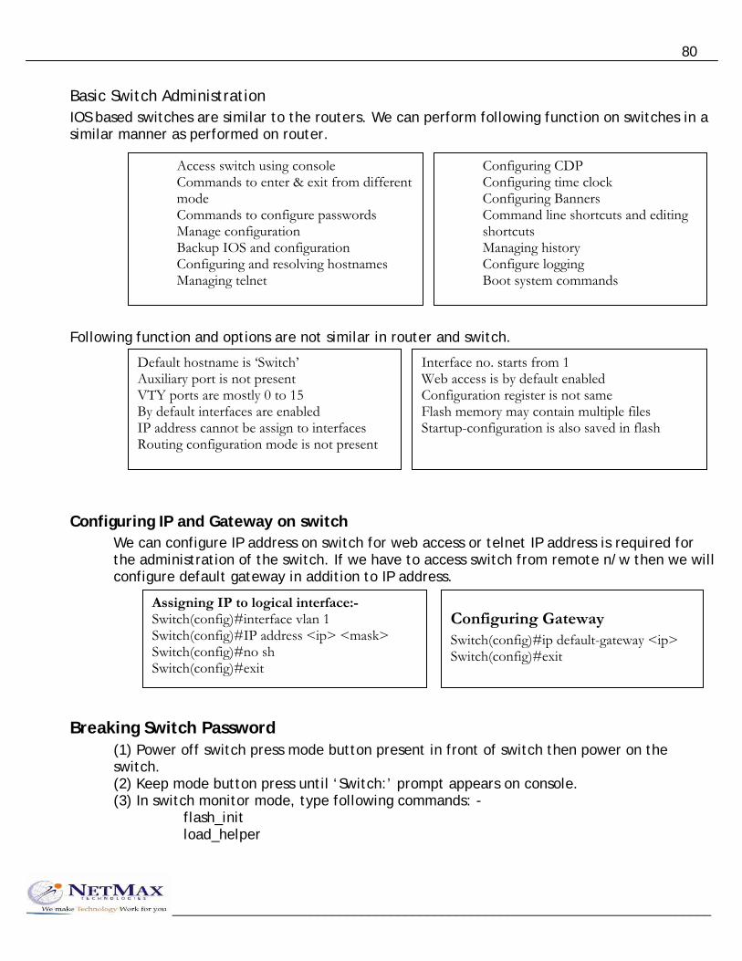
80
Basic Switch Administration IOS based switches are similar to the routers. We can perform following function on switches in a similar manner as performed on router.
Access switch using console Commands to enter & exit from different mode Commands to configure passwords Manage configuration Backup IOS and configuration Configuring and resolving hostnames Managing telnet
Configuring CDP Configuring time clock Configuring Banners Command line shortcuts and editing shortcuts Managing history Configure logging Boot system commands
Following function and options are not similar in router and switch. Default hostname is ‘Switch’
Auxiliary port is not present VTY ports are mostly 0 to 15 By default interfaces are enabled IP address cannot be assign to interfaces Routing configuration mode is not present
Interface no. starts from 1 Web access is by default enabled Configuration register is not same Flash memory may contain multiple files Startup-configuration is also saved in flash
Configuring IP and Gateway on switch We can configure IP address on switch for web access or telnet IP address is required for the administration of the switch. If we have to access switch from remote n/w then we will configure default gateway in addition to IP address.
Assigning IP to logical interface:- Switch(config)#interface vlan 1 Switch(config)#IP address <ip> <mask> Switch(config)#no sh Switch(config)#exit
Configuring Gateway Switch(config)#ip default-gateway <ip> Switch(config)#exit
Breaking Switch Password (1) Power off switch press mode button present in front of switch then power on the switch. (2) Keep mode button press until ‘Switch:’ prompt appears on console. (3) In switch monitor mode, type following commands: -
flash_init load_helper
__________________________________________________________________________

81
__________________________________________________________________________
rename flash:config.text flash:<anyname> dir flash: boot
(4) After booting switch will prompt to enter in initial configuration dialog. Enter ‘no’ here and type.
Switch>enable Rename flash:<anyname> Flash:config.text Configure memory
Change password and save config. Then copy run strat_config.
Cisco Hierarchal Model When we want to create a large sized LAN network then we may face following problems if we are going design the network in flat model.
High latency Conjunction between switches between switches Large broadcast domain
Cisco hierarchal model recommends three layer design of the network
Core layer Distribution layer Access layer
On each layer there are some rules which we have to follow Highest performance devices are connected on Core layer. Resources should be placed on Core layer. Polices should not be applied on core layer. On distribution layer, we can implement policies. Distribution and Core devices should be connected with high-speed links. Access layer devices are basic devices and may be non manageable.

82
Hierarchal model
After using hierarchal model the most of LAN problem will be solved but one problem still remain same that is all hosts will be in single broadcast domain. The no of broadcasts may impact the performance of the network. We have to implement following solution for this problem.
(1) Physical Segmentation (2) Logical Segmentation
Logical Segmentation of Network To perform logical segmentation, we have to create VLAN in the network. With the help of VLAN, we can logically divide the broadcast domain of the network. VLAN (Virtual LAN) VLAN provides Virtual Segmentation of Broadcast Domain in the network. The devices, which are member of same Vlan, are able to communicate with each other. The devices of different Vlan may communicate with each other with routing. So that different Vlan devices will use different n/w addresses. Vlan provides following advantages: -
(1) Logical Segmentation of network (2) Enhance network security
__________________________________________________________________________

83
Creating port based Vlan In port based Vlan, first we have to create a VLAN on switch then we have to add ports to the Vlan.
Commands to create Vlan Switch#config ter Switch(config)#vlan <no> Switch(config)#name <word>
Commands to configure ports for a Vlan Switch#conf ter Switch(config)#interface <type> <no>
By default, all ports are member of single vlan that is Vlan1. we can change vlan membership according to our requirement.
Commands to configure multiple ports in a vlan Switch#conf ter Switch(config)#interface range <type> <slot/port no (space)–(space) port no> Switch(config-if)#switchport access vlan <no> Switch(config-if)#exit
Example: - Suppose we want to add interface fast Ethernet 0/10 to 0/18 in vlan5
Switch#config ter Switch(config)#interface range fastethernet 0/10 – 18 Switch(config-if)#switchport access vlan 5 Switchconfig-if#exit
__________________________________________________________________________

84
To display mac address table Switch#sh mac-address-table
To Display Vlan and port membership
Switch#sh vlan
Trunking When there are multiple switches then we have to use trunk links to connect one switch with other. If we are not using trunk links then we have to connect one cable from each VLAN to the corresponding VLAN of the other switch.
Normal
Trunking
__________________________________________________________________________
85
__________________________________________________________________________
will perform trunking with the help of frame tagging. The trunk port will send data frames by adding a Vlan id information to the frame, at the receiving end vlan id information is removing from the end and according to the tag data is delivered to the corresponding vlan. There are two protocols to perform frame tagging.
(1) Inter switch link (2) IEEE 802.1 q
Configuring Trunking In cisco switches all switch ports may be configured in three modes
(1) Trunk desirable (default) (2) Trunk on (3) Trunk off
Switch#conf ter Switch(config)#interface <type> <no> Switch(config-if)#switchport mode <trunk|access|dynamic desirable> Switch(config-if)#exit
To configure Vlans allowed on Trunk By default all Vlans are allowed on Trunk port. We can add/remove a partucular Vlan from trunk port with following command
Switch#config ter Switch(config)#interface <type> <no> Switch(config-if)#switchport trunk allowed vlan <options> Options:- all, remove <vlan>, add <vlan>

86
Except <vlan>
To display trunk interfaces Switch#sh interface trunk Switch#sh interface <type> <no> trunk
Vlan Trunking Protocol (VTP) With the help of VTP, we can simplify the process of creating Vlan. In multiple switches, we can configure one switch as VTP server and all other switches will be configured as VTP client. We will create Vlans on VTP server switch. The server will send periodic updates to VTP client switches. The clients will create Vlans from the update received from the VTP server.
VTP server VTP server is a switch in which we can create, delete or modify Vlans. The server will send periodic updates for VTP clients.
VTP client On VTP client, we are not able to create, modify or delete Vlans. The client will receive and forward vtp updates. The client will create same Vlans as defined in vtp update.
__________________________________________________________________________

87
VTP Transparent Transparent is a switch, which will receive and forward VTP update. It is able to create, delete and modify Vlans locally. A transparent will not send its own VTP updates and will not learn any information from received vtp update.
Commands Switch#conf ter Switch(config)#vtp domain <name> Switch(config)#vtp password <word> Switch(config)#vtp mode <server|client|transparent> Switch(config)#exit
By default in cisco switches the VTP mode is set as VTP server with no domain and no password.
To display VTP status Switch#sh vtp status
VTP Pruning Pruning is the VTP feature through which a trunk link can be automatically disable, for a particular Vlan if neighbor switch does not contain ports in that Vlan. Vlan1 is not prun eligible.
__________________________________________________________________________
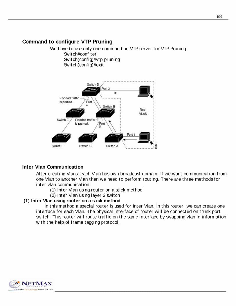
88
Command to configure VTP Pruning We have to use only one command on VTP server for VTP Pruning.
Switch#conf ter Switch(config)#vtp pruning Switch(config)#exit
Inter Vlan Communication After creating Vlans, each Vlan has own broadcast domain. If we want communication from one Vlan to another Vlan then we need to perform routing. There are three methods for inter vlan communication.
(1) Inter Vlan using router on a stick method (2) Inter Vlan using layer 3 switch
(1) Inter Vlan using router on a stick method In this method a special router is used for Inter Vlan. In this router, we can create one interface for each Vlan. The physical interface of router will be connected on trunk port switch. This router will route traffic on the same interface by swapping vlan id information with the help of frame tagging protocol.
__________________________________________________________________________

89
Configuration on Router Router#config ter Router(config)#interface fastethernet 0/0 Router(config-if)#no ip address Router(config-if)#no sh Router(config-if)#exit Router(config)#interface fastethernet 0/0.1 Router(config-if)#encapsulation dot1q 1 Router(config-if)#ip address 10.0.0.1 255.0.0.0 Router(config-if)#no sh Router(config-if)#exit
Router(config)#interface fastethernet 0/0.2 Router(config-if)#encapsulation dot1q 3 Router(config-if)#ip address 11.0.0.1 255.0.0.0 Router(config-if)#no sh Router(config-if)#exit Router(config)#interface fastethernet 0/0.3 Router(config-if)#encapsulation dot1q 5 Router(config-if)#ip address 12.0.0.1 255.0.0.0 Router(config-if)#no sh Router(config-if)#exit
Configuration on Core switch (1) Configure switch as VTP server (2) Create Vlans (3) Configure interface connected to router as Trunk (4) Configure interfaces connected to other switches as trunk (if required)
Configuration on Distribution layer switches (1) Configure switch as VTP client
__________________________________________________________________________

90
(2) Configure required interface as Trunk (optional) (3) Add ports to Vlan
Configuration on Pc Configure IP and Gateway
________________________________________________________________
Spanning Tree Protocol When we connect multiple switches with each other and multiple path exist from one switch to another switch then it may lead to the switching loop in the network. Multiple paths are used to create redundancy in the network. STP is only required when multiple path exist then there is possibility of loop in n/w.
Problems the occur with redundancy path (1) Multiple copies of the frame will be received by destination. (2) Frequent changes in the mac address table of switch. (3) A mac address may appear at multiple ports in a switch. (4) Packets may enter in the endless loop.
Spanning Tree Protocol will solve this problem by blocking the redundancy interface. So that only one path will remain active in the switches. If the primary path goes down then disabled link will become enable and data will be transferred through that path.
__________________________________________________________________________
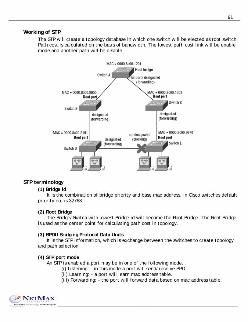
91
Working of STP The STP will create a topology database in which one switch will be elected as root switch. Path cost is calculated on the basis of bandwidth. The lowest path cost link will be enable mode and another path will be disable.
STP terminology (1) Bridge id It is the combination of bridge priority and base mac address. In Cisco switches default priority no. is 32768. (2) Root Bridge The Bridge/Switch with lowest Bridge id will become the Root Bridge. The Root Bridge is used as the center point for calculating path cost in topology. (3) BPDU Bridging Protocol Data Units It is the STP information, which is exchange between the switches to create topology and path selection. (4) STP port mode An STP is enabled a port may be in one of the following mode.
(i) Listening: - in this mode a port will send/receive BPD. (ii) Learning: - a port will learn mac address table. (iii) Forwarding: - the port will forward data based on mac address table.
__________________________________________________________________________
92
__________________________________________________________________________
(iv) Blocking: - the port is block to send/receive data by Spanning Tree Protocol. (v) Disable: - the port is administratively disabled.
Path cost calculation The links in switches will be enable or disabled on the basis of path cost. The path cost for each link is calculated according to following table.
Old IEEE New IEEE
Speed Cost Cost 10 Mb 100 100 100 Mb 10 19 1 Gb 1 4 10 Gb 1 2
To configure ports for forwarding mode directly Switch#config ter Switch(config)#interface <type> <no> Switch(config-if)#switchport host
Configuring port security In manageable switches, we can restrict the no. of mac addresses that a port can learn. Even we can specify the mac address statically with a command. With port security, we can also specify the action to be perform if port security violation is detected.
Switch#conf ter Switch(config)#interface <type> <no> Switch(config-if)#switchport port-security Switch(config-if)#switchport port-security maximum <no. of mac> Switch(config-if)#switchport port-security violation <shutdown|restrict|reject> Switch(config-if)#switchport port-security mac-address sticky Switch(config-if)#switchport port-security mac-address sticky <mac address> Switch(config-if)#exit

93
Network Security
Security Threats CisCO IOS solutions
Access Control List ACL are the basic security feature that is required in any network to control the flow of
traffic. Most of time our network may have servers and clients for which traffic control is required. We can also use ACL to classify the traffic. ACLs are used in features like QOS (Quality of Service), Prioritize traffic and interesting traffic for ISDN.
Classification Access Control List: - Types of ACL based on Protocol: - (1) IP Access Control List (2) IPX Access Control List (3) Appletalk Access Control List Types of ACL based on Feature: - (1) Standard ACL (2) Extended ACL
Types of ACL based on Access mode: - (1) Numbered ACL (2) Named ACL
Types of ACL based on Order of rules: - (1) Deny, permit (2) Permit, deny
Types of ACL based on direction: - (1) Inbound ACL (2) Outbound ACL
__________________________________________________________________________

94
Flow chart of Inbound ACL
A Packet is received
__________________________________________________________________________
No
The packet is passed to Routing Engine
Is there any Access-list applied on interface in Inbound direction?
Yes No The packet
is dropped. Is there any macthing rule in ACL from top-down order?
Yes Yes No The packet
is passed to RE
The packet is dropped.
Is it permit?
IP Standard ACL (Numbered) In Standard ACL, we are only able to specify source address for the filtering of packets. The syntax to create IP standard ACL are: - Router#conf ter Router(config)#access-list <no> <permit|deny> <source> Router(config)#exit <source> Single pc host 192.168.10.5 192.168.10.5 192.168.10.5 0.0.0.0

95
N/w 200.100.100.0 0.0.0.255 Subnet 200.100.100.32 0.0.0.15 All any
Applying ACL on interface Router#conf ter Router(config)#interface <type> <no> Router(config-if)#ip access-group <ACL no.> <in|out> Router(config-if)#exit
Rule for applying ACL Only one ACL can be applied on each interface, in each direction for each protocol. Example: - Suppose we want to allow Internet only for 192.168.10.32 – 70. Internet Router(config)#access-list 25 permit 192.168.10.32 0.0..31
Router(config)#access-list 25 permit 192.168.10.64 0.0.0.3 Router(config)#access-list 25 permit 192.168.10.68 Router(config)#access-list 25 permit 192.168.10.69 Router(config)#access-list 25 permit 192.168.10.70 Router(config)#interface serial 0 Router(config-if)#ip access-group 25 out
Router
IP Standard ACL (Named) In Numbered ACL editing feature is not available that is we are not able to delete single rule from the ACL. In Named ACL editing feature is available. Router#config ter Router(config)#ip access-list standard <name> Router(config-std-nacl)#<deny|permit> <source> Router(config-std-nacl)#exit
__________________________________________________________________________
Router#conf ter Router(config)#ip access-list standard abc Router(config-std-nacl)#deny 172.16.0.16 Router(config-std-nacl)#deny 172.16.0.17 Router(config-std-nacl)#deny 172.16.0.18 Router(config-std-nacl)#permit any Router(config-std-nacl)#exit
To modify the ACL Router#conf ter Router(config)#ip access-list standard abc Router(config-std-nacl)#no deny 172.16.0.17 Router(config-std-nacl)#exit

96
__________________________________________________________________________
To control Telnet access using ACL If we want to control telnet with the help of ACL then we can create a standard ACL and apply this ACL on vty port. The ACL that we will create for vty will be permit – deny order. Example: - suppose we want to allow telnet to our router from 192.168.10.5 & 200.100.100.30 pc. Router#conf ter Router(config)#access-list 50 permit 192.168.10.5 Router(config)#access-list 50 permit 192.168.10.30 Router(config)#access-list 50 deny Router(config)#line vty 0 4 Router(config-line)#access-class 50 in Router(config)#exit IP Extended ACL (Numbered) Extended ACL are advanced ACL. ACL, which can control traffic flow on the basis of five different parameters that are: - (i) Source address (ii) Destination address (iii) Source port (iv) Destination port (v) Protocol (layer 3/layer 4)
The syntax to create Extended ACL Router#conf ter Router(config)#access-list <no> <deny|permit> <protocol> <source> [<s.port>] <destination> [<d.port>] router(config)#exit <no> -> 100 to 199 <protocol> -> layer 3 or layer 4 IP TCP UDP ICMP IGRP <Source port> no (1 to 65535) or <Destination port> telnet/www/ftp etc. <Source> <Destination>
Example rules of Extended ACL Router(config)#access-list 140 deny ip 192.168.10.3 0.0.0.0 any (All tcp/ip data is denied from source 192.168.10.3 to any destination)

97
__________________________________________________________________________
Router(config)#access-list 120 permit ip any any (All tcp/ip data permit from any source to any destination) Router(config)#access-list 145 deny tcp any host 200.100.100.5 (All tcp data is denied from any source to host 200.100.100.5) Router(config)#access-list 130 permit tcp any host 200.100.100.10 eq 80 (All tcp based data from any source is allowed to access destination 200.100.100.10 on port no. 80 that is www(http) ) – web access Router(config)#access-list 130 permit udp any host 200.100.100.10 eq 53 (Any pc is able to access our DNS service running on port no. 53) Router(config)#access-list 150 deny tcp any any eq 23 [or telnet] (Telnet traffic is not allowed) Router(config)#access-list 160 deny icmp any any (All icmp data from any source to any destination is denied)
To display ACL Router#show access-lists or Router#show access-list <no>
To display ACL applied on interface Router#show ip interface
Example: - Extended ACL Suppose we want to control inbound traffic for our network. ACL should be designed according the following policy. (1) Access to web server (200.100.100.3) is allowed from any source. (2) FTP server (200.100.100.4) should be accessible only from branch office n/w (200.100.175.0/24). (3) ICMP & Telnet should be allowed only from remote pc 200.100.175.80 (4) Any pc can access DNS (200.100.100.8)
200.100.175.x
Router

98
Router 200.100.100.x
Router(config)#access-list 130 permit tcp any host 200.100.100.3 eq 80 Router(config)#access-list 130 permit tcp 200.100.175.0 0.0.0.255 200.100.100.4 0.0.0.0 Eq 21 Router(config)#access-list 130 permit icmp 200.100.175.80 0.0.0.0 any Router(config)#access-list 130 permit tcp 200.100.175.80 0.0.0.0 any eq 23 Router(config)#access-list 130 permit udp any host 200.100.100.8 eq 53
Switch port ACL You can only apply port ACLs to layer 2 interfaces on your switches because they are only supported on physical layer 2 interfaces. You can apply them as only inbound lists on your interfaces, and you can use only named lists as well. Extended IP access lists use both source and destination addresses as well as optional protocol information and port number. There are also MAC extended access lists that use source and destination MAC addresses and optional protocol type information. Switches scrutinize all inbound ACLs applied to a certain interface and decide to allow traffic through depending on whether the traffic is a good match to the ACL or not. ACLs can also be used to control traffic on VLANs. You just need to apply a port ACL to a trunk port.
Switch#conf ter Switch(config)#mac access-list extended abc Switch(config-ext-mac)#deny any host 000d.29bd.4b85 Switch(config-ext-mac)#permit any any Switch(config-ext-mac)#do show access-list Switch(config-ext-mac)#int f0/6 Switch(config-if)#mac access-group abc
Lock and Key (Dynamic ACLs)
These ACLs depends on either remote or local Telnet authentication in combination with extended ACLs. Before you can configure a dynamic ACL, you need to apply an extended ACL on your router to stop the flow of traffic through it.
__________________________________________________________________________

99
__________________________________________________________________________
Reflexive ACLs These ACLs filter IP packets depending upon upper-layer session information, and they often permit outbound traffic to pass but place limitations on inbound traffic. You can not define reflexive ACLs with numbered or standard IP ACLs, or any other protocol ACLs. They can be used along with other standard or static extended ACLs, but they are only defined with extended named IP ACLs.
Time-Based ACLs In this you can specify a certain time of day and week and then identity that particular period by giving it a name referenced by a task. The reference function will fall under whatever time constraints you have dictated. The time period is based upon the router’s clock, but it is highly recommended that using it in conjunction with Network Time Protocol (NTP) synchronization.
Router#conf ter Router(config)#time-range no-http Router(config-time-range)#periodic <Wednesday|weekdays|weekend> 06:00 to 12:00 Router(config-time-range)#exit Router(config)#time-range tcp-yes Router(config-time-range)#periodic weekend 06:00 to 12:00 Router(config-time-range)#exit Router(config)ip access-list extended time Router(config-ext-nacl)#deny tcp any any eq www time-range no-http Router(config-ext-nacl)#permit tcp any any time-range tcp-yes Router(config-ext-nacl)#interface f0/0 Router(config-if)#ip access-group time in Router(config-if)#do show time-range
Remarks Remarks are the comments or remarks regarding the entries you have made in both your IP Standard and Extended ACLs.
Router#conf ter Router(config)#access-list 110 remark <remark words> permit rahul from admin only to sale Router(config)#access-list 110 permit ip host 172.16.10.1 172.16.20.0 0.0.0.255 Router(config)#access-list 110 deny ip 172.16.10.0 0.0.0.255 172.16.20.0 0.0.0.255

100
__________________________________________________________________________
Security Configuration using SDM Content Based ACL (CBAC)
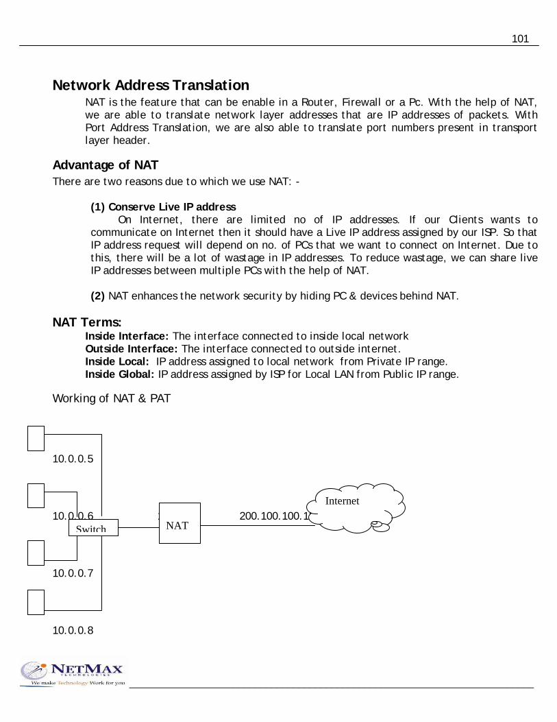
101
Network Address Translation NAT is the feature that can be enable in a Router, Firewall or a Pc. With the help of NAT, we are able to translate network layer addresses that are IP addresses of packets. With Port Address Translation, we are also able to translate port numbers present in transport layer header.
Advantage of NAT There are two reasons due to which we use NAT: -
(1) Conserve Live IP address On Internet, there are limited no of IP addresses. If our Clients wants to communicate on Internet then it should have a Live IP address assigned by our ISP. So that IP address request will depend on no. of PCs that we want to connect on Internet. Due to this, there will be a lot of wastage in IP addresses. To reduce wastage, we can share live IP addresses between multiple PCs with the help of NAT. (2) NAT enhances the network security by hiding PC & devices behind NAT.
NAT Terms: Inside Interface: The interface connected to inside local network Outside Interface: The interface connected to outside internet. Inside Local: IP address assigned to local network from Private IP range. Inside Global: IP address assigned by ISP for Local LAN from Public IP range.
Working of NAT & PAT 10.0.0.5 10.0.0.6 10.0.0.1 200.100.100.12 10.0.0.7
NAT Switch
Internet
10.0.0.8
__________________________________________________________________________

102
10.0.0.5 200.100.100.12 1080
Port Translation 1100
10.0.0.6 200.100.100.12 1085
10.0.0.7 200.100.100.12 1024
10.0.0.8 200.100.100.12 1024
Types of NAT
Static NAT This NAT is used for servers in which one Live IP is directly mapped to one Local IP. This NAT will forward on the traffic for the Live IP to the Local PC in the n/w.
Static NAT 200.1.1.5 = 192.168.10.6
__________________________________________________________________________
Live 200.1.1.5
Internet Router
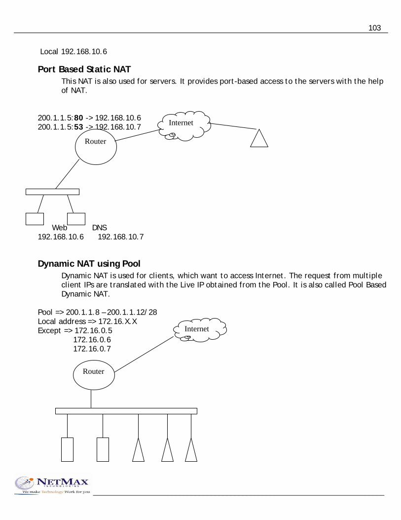
103
Local 192.168.10.6
Port Based Static NAT This NAT is also used for servers. It provides port-based access to the servers with the help of NAT.
200.1.1.5:80 -> 192.168.10.6 200.1.1.5:53 -> 192.168.10.7
Router
Internet
__________________________________________________________________________
Web DNS 192.168.10.6 192.168.10.7
Dynamic NAT using Pool Dynamic NAT is used for clients, which want to access Internet. The request from multiple client IPs are translated with the Live IP obtained from the Pool. It is also called Pool Based Dynamic NAT.
Pool => 200.1.1.8 – 200.1.1.12/28 Local address => 172.16.X.X Except => 172.16.0.5 172.16.0.6 172.16.0.7
Internet
Router

104
__________________________________________________________________________
Web Server DNS Full access 172.16.X.X 172.16.0.5 172.16.0.6 172.16.0.7 Pool allotted => 200.1.1.0 – 15/28 Server Static => 200.1.1.3 = 172.16.0.7 Port Based Static NAT 200.1.1.4:53 = 172.16.0.6 200.1.1.4:80 = 172.16.0.5 Client Dynamic NAT Pool => 200.1.1.8 – 200.1.1.12/28 Local address => 172.16.0.X
Configuring NAT Router#conf ter Router(config)#int serial 0 Router(config-if)#ip nat outside Router(config-if)#int eth 0 Router(config-if)#ip nat inside Router(config-if)#exit Router(config)#ip nat inside source static 172.16.0.7 200.1.1.3 Router(config)#ip nat inside source static tcp 172.16.0.5 80 200.1.1.4 80 Router(config)#ip nat inside source static udp 172.16.0.6 53 200.1.1.4 53 Router(config)#access-list 30 permit any Router(config)#ip nat pool abc 200.1.1.8 200.1.1.12 netmask 255.255.255.240 Router(config)#ip nat inside source list 30 pool abc overload
To display NAT translation Router#sh ip nat translations (after ping any address, it shows ping details)
To clear IP NAT Translation Router#clear ip nat Translation

105
Wide Area Network The network that is design for long distance communication is called Wide Area Network. A WAN network uses WAN protocols, WAN interface card to communicate with remote network.
Point-to-Point Circuit Switching Packet Switching Cell Switching
WAN
Leased line ISDN Frame Relay ATM MLLN PSTN X.25 Radio Link For 2 locations Unlimited Maximum Maximum
Factors to be considered while selecting a WAN technology (1) No. of locations (2) Hours of connectivity (3) Speed (4) Cost (Bandwidth + Distance) (5) Reliability
WAN Encapsulation WAN encapsulation is used to convert a packet into frame and transfer data to WAN links, Different type of encapsulation are designed for different WAN technologies. The general format of WAN encapsulation is: -
Flag Address Control Data FCS Flag
FH Packet FT
Common WAN Encapsulation Point-to-Point High level data link control HDLC Point-to-Point, Point-to-Point Protocol PPP Circuit Switch PPP Frame Relay Frame Relay Cisco Frame Relay Frame Relay IETF X.25 Link Access Procedure Based LAPB
__________________________________________________________________________

106
ISDN Link Access Procedure Based for D channel LAPD ATM ATM Adaptation layer 5 AAL5
Point-to-Point WAN technologies These WAN technologies are used to connect two locations with each other. It is the 24-hour high speed and reliable connectivity. We can setup this WAN technology in three steps: - Step 1: - Connect the devices according to topology. Step 2: - Configure Modems. Step 3: - Configure Router.
Step 1
Point-to-Point WAN Topology (a) Campus n/w or Drop wire n/w V.35 Line Line RS 232 EIA/TIA 530 2 wire TP Or 4 wire TP DB-60 Smart Serial RJ-45 * Distance depends on modems & mostly up to 10-15 kms.
Modem
Serial Router eth
Router
(b) Leased line via Service Provided
__________________________________________________________________________

107
G703 G704 Line Local Loop Local Loop Line V.35 RS 232, EIA/TIA 530 SS, DB-60
Modem
Modem
Modem
Exchange Mux Mux
Modem
R R
(c) Managed Leased Line n/w (MLLN)
Exchange MLLN MUX
MLLN MUX
MLLN Modem
MLLN Modem
Router
Router
__________________________________________________________________________

108
(d) Radio Link Antenna V.35 RS 232 EIA 530 DB-60 Smart Serial
Radio Modem
Radio Modem
Router
Router
(e) Radio Link using IDU & ODU ODU ODU UTP or Coaxial IDU IDU ODU – Out Door Unit IDU – In Door Unit
Radio Modem
Radio Modem
Radio Modem
Radio Modem
Router
Router
__________________________________________________________________________

109
Line
4 Wire 2 Wire 1 ------- 1 2 ------- Loop 1 2 3 3 4 ------- Loop2 4 ------- Signal 5 ------ - 5 ------- 6 6 7 7 8 8
Step 2 Configurations of Modems
We have to configure various parameters in the modem. There are three different methods to configure these parameters according to Modem.
Three methods for configuration of router are:
1) Configuration of modem using Jumper setting/ Dip switches. 2) Configuration of modem using LCD menu. 3) Configuration of Modem using Console/ Terminal.
Step 3 Configuration of Router To configure Router for a Leased line scenario or Point-to-Point n/w, we have to set following parameters: -
1) IP addresses 2) IP routing 3) WAN encapsulation
__________________________________________________________________________
172.16.0.1 172.16.0.2 192.168.5.1 10.0.0.1

110
In Point-to-Point WAN n/w any type of routing be perform on routers.
WAN Encapsulation Two routers interfaces in Point-to-Point WAN must required to have same WAN encapsulation. Two types of WAN encapsulation are supported in this type of network.
(1) HDLC (2) PPP
HDLC PPP
__________________________________________________________________________
Same Manufacturer PPP Different Manufacturer
By default, Cisco routers will use Cisco HDLC encapsulation. We can change encapsulation by following command: -
Router#conf ter Router(config)#interface <type> <no> Router(config-if)#encapsulation ppp|hdlc
____________________________________________________________________ High Level Data Link Control
HDLC is the modified form of SDLC (Synchronous Data Link Control). SDLC was developed by IBM for router to main frame communication. HDLC is modified for router-to-router communication. Most of manufacturer has developed their proprietary HDLC protocol. So HDLC from one manufacturer is not compatible for other. HDLC encapsulation is designed for Point-to-Point router communication. In HDLC no addressing is required, but still all station address is used in encapsulation. HDLC provides only basic features and error checking for the frame.

111
PPP – Point-to-Point Protocol
PPP is an open standard WAN protocol that can be used in Point-to-Point and circuit switching networks. PPP provides various advantages as compared to HDLC. PPP has following special features: -
(1) Authentication (2) Multi Link (3) Compression (4) Call Back
PPP at OSI layer A P TCP/IP S IPX/SPX
__________________________________________________________________________
T N Lan, Wan Protocols DL
PPP
HDLC
LAPB
EE 8023 ARPA
P Network D A NCP T ------------------- A LCP PPP L I -------------------- N K HDLC Physical

112
Three Phases of PPP (1) Link Control Protocol (LCP) This protocol negotiates the basic feature of PPP. It exchanges the parameter and option to be used with link. LCP supported features are: - Authentication, Compression, Multi link & Call back (2) Authentication Phase - optional In this phase authentication is performed with peers with the help of one of the following protocol.
(i) Password Authentication Protocol (ii) Challenge Handshake Authentication Protocol (iii) Microsoft CHAP (iv) Shiva PAP (clear text)
(3) Network Control Protocol Phase (NCP) In this phase parameters for routed protocol are established. In NCP, there is one module for each router protocol.
IPCP for TCP/IP IPXCP for IPX/SPX CDPCP for CDP etc.
Configuring Authentication in PPP Example: - Router 1 Router 2
S1 S0
Router 1 Router#config ter Router(config)#int serial 0 Router(config-if)# encapsulation ppp Router(config-if)# ppp authentication chap Router(config-if)#ip address 10.0.0.1 255.0.0.0 Router(config-if)#no sh Router(config-if)#exit Router(config)#hostname chd Router(config)#username ldh password net123 Router(config)#exit Router 2 Router#config ter
__________________________________________________________________________

113
__________________________________________________________________________
Router(config)#int serial 1 Router(config-if)#encapsulation ppp Router(config-if)#ppp authentication chap Router(config-if)#ip address 10.0.0.2 255.0.0.0 Router(config-if)#no sh Router(config-if)#exit Router(config)#hostname ldh Router(config)#username chd password net123 Router(config)#exit
Configuring Compression in PPP In PPP, one of the following three protocols can be used for compression
(1) Stac (2) Predictor (3) Microsoft Point-to-Point Compression
Router#config ter Router(config)#interface <type> <no> Router(config-if)#encapsulation ppp Router(config-if)#compress <Stac|MPPC|Predictor> Router(config-if)#exit
To display Compression Router#show compress
PPP debug commands Router#debug ppp error Router#debug ppp authentication Router#debug ppp negotiation
To display PPP status Router#show interface LCP Open LCP Closed LCP Request sent LCP Listen IPCP Open IPCP Closed

114
CDPCP Open CDPCP Closed
________________________________________________________________
Packet Switching Packet Switching is the wan technology in which all devices are connected to the packet switching exchange. The devices will request packet switching exchange to create a virtual connection then data is transferred over the virtual connection. It is possible to create more than one virtual connection and transfer data over them one by one.
Example of Packet Switching Technology are: - (1) X.25 (2) Frame Relay
Frame Relay Frame Relay is the Packet switching technology in which virtual connections are established. The frame relay supports only permanent virtual connections. Frame used special addresses called DLCI to create common and virtual connections.
FR SW
Frame Relay Topology V.35 232 4 wire Tp 530 Line Local loop Line
FR Modem
FR Modem
V.35, RS232, EIA 530
__________________________________________________________________________
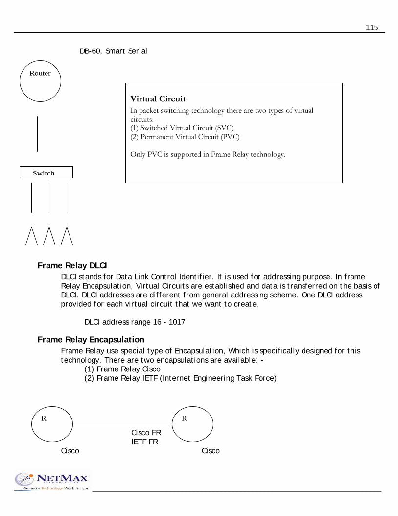
115
DB-60, Smart Serial
__________________________________________________________________________
Router
Virtual Circuit In packet switching technology there are two types of virtual circuits: - (1) Switched Virtual Circuit (SVC) (2) Permanent Virtual Circuit (PVC) Only PVC is supported in Frame Relay technology.
Switch
Frame Relay DLCI DLCI stands for Data Link Control Identifier. It is used for addressing purpose. In frame Relay Encapsulation, Virtual Circuits are established and data is transferred on the basis of DLCI. DLCI addresses are different from general addressing scheme. One DLCI address provided for each virtual circuit that we want to create.
DLCI address range 16 - 1017
Frame Relay Encapsulation Frame Relay use special type of Encapsulation, Which is specifically designed for this technology. There are two encapsulations are available: -
(1) Frame Relay Cisco (2) Frame Relay IETF (Internet Engineering Task Force)
Cisco FR IETF FR
R R
Cisco Cisco

116
__________________________________________________________________________
IETF FR
R R
Non Cisco any
Frame Relay Local Management Interface LMI are the keep-alive signals, which are used to keep the virtual circuit up and running. LMI are exchange between frame relay switch and router. We have to set same LMI on router as specified by the service provider. There are three types of LMI that we can use
(1) CISCO (2) Q933a (3) ANSI Cisco routers may use AUTO LMI in which router will automatically detect the required LMI.
Configuring Frame Relay Point to Point connectivity Cisco ANSI 300 for R2 400 for R1 encap: - Cisco FR
M M
M M
SW FR
SW

117
192.168.10.1 192.168.10.2 172.16.0.1 172.30.0.1
R1 R2
R1 Router#config ter Router(config)#int eth0 Router(config-if)#ip address 172.16.0.1 255.255.0.0 Router(config-if)#no sh Router(config-if)#exit Router(config)#ip route 172.30.0.0 255.255.0.0 192.168.10.2 Router(config)#int serial 0 Router(config-if)#encapsulation frame-relay Router(config-if)#frame-relay lmi-type cisco Router(config-if)#ip address 192.168.10.1 255.255.255.0 Router(config-if)#frame-relay interface-dlci 300 Router(config-dlci)#exit Router(config-if)#frame-relay map ip 192.168.10.2 300 Router(config-if)#no sh Router(config-if)#exit
R2 Router#config ter Router(config)#int eth0 Router(config-if)#ip address 172.30.0.1 255.255.0.0 Router(config-if)#no sh Router(config-if)#exit Router(config)#ip route 172.16.0.0 255.255.0.0 192.168.10.1 Router(config)#int serial 0 Router(config-if)#encapsulation frame-relay Router(config-if)#frame-relay lmi-type cisco Router(config-if)#ip address 192.168.10.2 255.255.255.0 Router(config-if)#frame-relay interface-dlci 400
__________________________________________________________________________

118
__________________________________________________________________________
Router(config-dlci)#exit Router(config-if)#frame-relay map ip 192.168.10.1 400 Router(config-if)#no sh Router(config-if)#exit
Frame Relay point to multipoint In frame relay we can communicate with multiple locations by using virtual circuits. So if we want to establish multipoint connectivity then there are two methods: Using Point-to-point sub-interface Using multipoint sub-interface Creating point-to-point sub-interface is preferred method.
R1 Router#config ter Router(config)#int eth0 Router(config-if)#ip address 172.16.0.1 255.255.0.0 Router(config-if)#no sh Router(config-if)#exit Router(config)#ip route 172.30.0.0 255.255.0.0 192.168.10.2 Router(config)#ip route 172.20.0.0 255.255.0.0 172.16.0.2 Router(config)#ip route 172.25.0.0 255.255.0.0 10.0.0.2 Router(config)#int serial 0 Router(config-if)#encapsulation frame-relay Router(config-if)#frame-relay lmi-type cisco Router(config-if)#no ip address Router(config-if)#no shutdown Router(config-if)#exit Router(config)#interface serial 0.1 point-to-point Router(config-if)#ip address 192.168.10.1 255.255.255.0 Router(config-if)#frame-relay map ip 192.168.10.2 300 Router(config-if)#no sh Router(config-if)#exit Router(config)#interface serial 0.2 point-to-point Router(config-if)#ip address 172.16.0.1 255.255.255.0
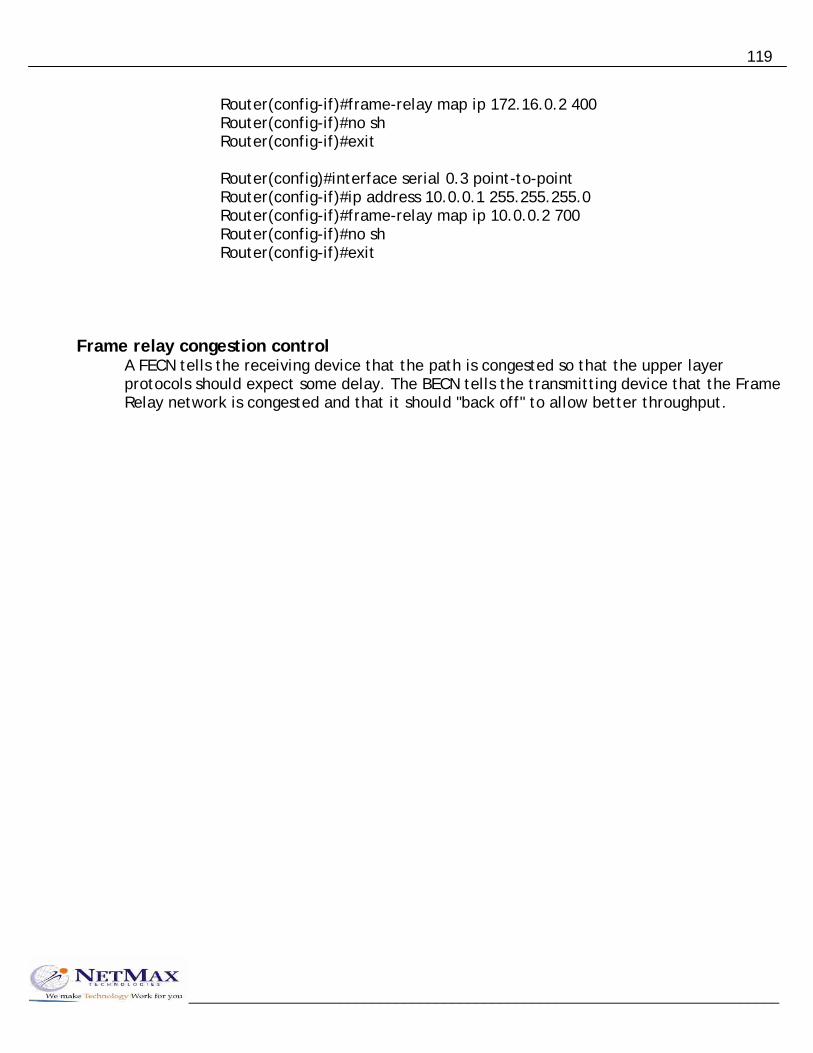
119
__________________________________________________________________________
Router(config-if)#frame-relay map ip 172.16.0.2 400 Router(config-if)#no sh Router(config-if)#exit Router(config)#interface serial 0.3 point-to-point Router(config-if)#ip address 10.0.0.1 255.255.255.0 Router(config-if)#frame-relay map ip 10.0.0.2 700 Router(config-if)#no sh Router(config-if)#exit
Frame relay congestion control A FECN tells the receiving device that the path is congested so that the upper layer protocols should expect some delay. The BECN tells the transmitting device that the Frame Relay network is congested and that it should "back off" to allow better throughput.