jim doherty cisco networking simplified (2nd edition)
TRANSCRIPT
Cisco Press
800 East 96th Street
Indianapolis, IN 46240 USA
Cisco Networking SimplifiedSecond Edition
Jim Doherty
Neil Anderson
Paul Della Maggiora
Illustrations by Nathan Clement
ii
Cisco Networking Simplified, Second Edition
Jim Doherty, Neil Anderson, Paul Della Maggiora
Copyright© 2008 Cisco Systems, Inc.
Published by:
Cisco Press
800 East 96th Street
Indianapolis, IN 46240 USA
All rights reserved. No part of this book may be reproduced or transmitted in any form or by any means, electronic or
mechanical, including photocopying, recording, or by any information storage and retrieval system, without written permis-
sion from the publisher, except for the inclusion of brief quotations in a review.
Printed in the United States of America
First Printing December 2007
Library of Congress Cataloging-in-Publication Data:
Doherty, Jim.
Cisco networking simplified / Jim Doherty, Neil Anderson, Paul Della Maggiora. -- 2nd ed.
p. cm.
ISBN 978-1-58720-199-8 (pbk.)
1. Computer networks. I. Anderson, Neil. II. Della Maggiora, Paul L.
III. Title.
TK5105.8.C57D44 2007
004.6—dc22
2007046376
ISBN-13: 978-1-58720-199-8
ISBN-10: 1-58720-199-2
Warning and Disclaimer
This book is designed to provide information about Cisco networking. Every effort has been made to make this book as com-
plete and accurate as possible, but no warranty or fitness is implied.
The information is provided on an “as is” basis. The authors, Cisco Press, and Cisco Systems, Inc. shall have neither liability
nor responsibility to any person or entity with respect to any loss or damages arising from the information contained in this
book or from the use of the discs or programs that may accompany it.
The opinions expressed in this book belong to the authors and are not necessarily those of Cisco Systems, Inc.
Publisher
Paul Boger
Associate Publisher
Dave Dusthimer
Cisco Representative
Anthony Wolfenden
Cisco Press Program Manager
Jeff Brady
Executive Editor
Karen Gettman
Managing Editor
Patrick Kanouse
Development Editor
Sheri Cain
Senior Project Editor
Tonya Simpson
Copy Editor
Gayle Johnson
Technical Editors
Bradley Mitchell, Matthew Stein
Editorial Assistant
Vanessa Evans
Cover Designer
Louisa Adair
Interior Design and Composition
Mark Shirar
Proofreader
Paula Lowell
Indexer
Heather McNeil

iii
Trademark Acknowledgments
All terms mentioned in this book that are known to be trademarks or service marks have
been appropriately capitalized. Cisco Press or Cisco Systems, Inc., cannot attest to the
accuracy of this information. Use of a term in this book should not be regarded as affecting
the validity of any trademark or service mark.
Feedback Information
At Cisco Press, our goal is to create in-depth technical books of the highest quality and value.
Each book is crafted with care and precision, undergoing rigorous development that
involves the unique expertise of members from the professional technical community.
Readers’ feedback is a natural continuation of this process. If you have any comments
regarding how we could improve the quality of this book, or otherwise alter it to better suit
your needs, you can contact us through e-mail at [email protected]. Please make sure
to include the book title and ISBN in your message.
We greatly appreciate your assistance.
Corporate and Government Sales
The publisher offers excellent discounts on this book when ordered in quantity for bulk
purchases or special sales, which may include electronic versions and/or custom covers and
content particular to your business, training goals, marketing focus, and branding interests.
For more information, please contact:
U.S. Corporate and Government Sales
1-800-382-3419
For sales outside the United States, please contact:
International Sales
iv
About the Technical Reviewers
Bradley Mitchell is a freelance writer covering technology topics, specializing in computer
networking. Online, he has produced the About.com Wireless/Networking site since 2000.
He also is a senior engineer at Intel Corporation. Over the past 14 years at Intel he has
served in various capacities for research and development of software and network systems.
He obtained a master’s degree in computer science from the University of Illinois and a
bachelor’s degree from MIT.
Matthew Stein is a marketing manager for Enterprise Solutions Marketing (ESM) at Cisco.
In his role, he defines and develops network service solutions for the enterprise market,
which spans multiple networking technologies and drives business growth, performance, and
IT efficiencies. He previously worked in the Wireless Business Unit of Cisco, where he was
responsible for leading the development and marketing integration of Enterprise networking
solutions for the Cisco Aironet Wireless product line. Before joining Cisco in May 2000,
Stein served as a database design system engineer for GE Lighting. He also was a system
engineer for the Center for Brain Imaging at the Medical College of Wisconsin. He received
his bachelor of science degree in electrical engineering from Case Western Reserve
University.
v
Acknowledgments
Jim and Neil would like to thank the following people:
Our families, whom we lied to after the last book, when we said we would not do this
again, and who put up with our working late nights and weekends. This time, we mean it.
Our publisher and the fine team at Cisco Press and Pearson Education. We would especially
like to thank our editor, Sheri Cain, who bravely agreed to join us on another project; our
production manager, Patrick Kanouse; Chris Cleveland; Karen Gettman; Tonya Simpson;
Jennifer Gallant; Gayle Johnson; and the rest of the Cisco Press team working behind the
scenes.
As always, we want to thank our illustrator, Nathan Clement at Stickman Studios
(http://www.stickman-studio.com/), who never fails to deliver a great product.
A special thanks to our technical reviewers, Bradley Mitchell and Matthew Stein, who
worked hard on our readers’ behalf to keep us honest and accurate.
We would also like to thank the following people at Cisco who helped with content and
questions: Tim Szigeti, Brian Cox, Ron Maxam, John Strika, Mike Herbert, Jason Frazier,
Max Ardica, Stephenie Chastain, Joel King, May Konfong, Damon Li, Martin Pueblas,
Chris O’Brien, and Roland Dobbins.
Dedications
This book is dedicated to Bradley Mitchell.
Bradley was introduced to us by our publisher as a technical reviewer when we wrote our
first book together back in 2004 (Home Networking Simplified).
We were so happy with his effort, his insightful comments, and his technical expertise that
we asked him to be a reviewer on the next book. And on the one after that. And so on and
so on until we look back and realize that over five titles, the entire set of the Networking
Simplified series, Bradley has been a critical part of our writing team, and our books are bet-
ter for it.
This is not to say that our other reviewers along the way have not been great. They have.
But Bradley catches errors that no one else catches (writers, reviewers, publishing team). He
is constantly making sure that we have our audience in mind and advises us to rewrite sec-
tions when have gone off the deep end. And when we refer to a 128-digit number (and then
feel compelled to give an example of one), Bradley actually counts the digits, lets us know
that we left off two 0s at the beginning, and then reminds us that you probably don’t care
about seeing the actual number anyway.
It’s nearly impossible to attain perfection in a book like this, but Bradley gets us much, much
closer than we would have otherwise. This book, and all our books, are better than they
would have been, because Bradley took the time to help us make them better.
We’ve never had a chance to meet him in person. When we do, we’ll shake his hand and buy
him a beer (or maybe five—one for each book). In the meantime, we hope this is enough.

vii
Part II: Networking Infrastructure . . . . . . . . . . . . . . . . . . . . . . . . . . . . . . . . . . . . . .33
Ethernet . . . . . . . . . . . . . . . . . . . . . . . . . . . . . . . . . . . . . . . . . . . . . . . . . . . . . . . . . . . . .34
History of Ethernet . . . . . . . . . . . . . . . . . . . . . . . . . . . . . . . . . . . . . . . . . . . . . . . . . . . . . . . . . . . . .35
What Is Ethernet? . . . . . . . . . . . . . . . . . . . . . . . . . . . . . . . . . . . . . . . . . . . . . . . . . . . . . . . . . . . . . . .35
Evolution of Ethernet . . . . . . . . . . . . . . . . . . . . . . . . . . . . . . . . . . . . . . . . . . . . . . . . . . . . . . . . . . . .36
At-a-Glance: Ethernet . . . . . . . . . . . . . . . . . . . . . . . . . . . . . . . . . . . . . . . . . . . . . . . . . . . . . . .37–39
Reducing Collisions on Ethernet . . . . . . . . . . . . . . . . . . . . . . . . . . . . . . . . . . . . . . . . . . . . . . . .40
LAN Switching . . . . . . . . . . . . . . . . . . . . . . . . . . . . . . . . . . . . . . . . . . . . . . . . . . . . . . . .42
Fast Computers Need Faster Networks . . . . . . . . . . . . . . . . . . . . . . . . . . . . . . . . . . . . . . . .43
Switching Basics: It’s a Bridge . . . . . . . . . . . . . . . . . . . . . . . . . . . . . . . . . . . . . . . . . . . . . . . . . .43
Switching Ethernets . . . . . . . . . . . . . . . . . . . . . . . . . . . . . . . . . . . . . . . . . . . . . . . . . . . . . . . . . . . .44
Switches Take Over the World . . . . . . . . . . . . . . . . . . . . . . . . . . . . . . . . . . . . . . . . . . . . . . . . .44
At-a-Glance: Switching . . . . . . . . . . . . . . . . . . . . . . . . . . . . . . . . . . . . . . . . . . . . . . . . . . . . .45–47
Spanning Tree . . . . . . . . . . . . . . . . . . . . . . . . . . . . . . . . . . . . . . . . . . . . . . . . . . . . . . . .48
Network Loops . . . . . . . . . . . . . . . . . . . . . . . . . . . . . . . . . . . . . . . . . . . . . . . . . . . . . . . . . . . . . . . . .49
Sometimes, the Earth Is Flat . . . . . . . . . . . . . . . . . . . . . . . . . . . . . . . . . . . . . . . . . . . . . . . . . . . .49
Preventing Network Loops . . . . . . . . . . . . . . . . . . . . . . . . . . . . . . . . . . . . . . . . . . . . . . . . . . . . .49
Spanning-Tree Fundamentals . . . . . . . . . . . . . . . . . . . . . . . . . . . . . . . . . . . . . . . . . . . . . . . . . . .49
At-a-Glance: Spanning Tree . . . . . . . . . . . . . . . . . . . . . . . . . . . . . . . . . . . . . . . . . . . . . . . .51–53
Routing . . . . . . . . . . . . . . . . . . . . . . . . . . . . . . . . . . . . . . . . . . . . . . . . . . . . . . . . . . . . . .54
Routers . . . . . . . . . . . . . . . . . . . . . . . . . . . . . . . . . . . . . . . . . . . . . . . . . . . . . . . . . . . . . . . . . . . . . . . . .55
Routers Talk Among Themselves to Find Routes . . . . . . . . . . . . . . . . . . . . . . . . . . . . . . .55
Routers Route Packets . . . . . . . . . . . . . . . . . . . . . . . . . . . . . . . . . . . . . . . . . . . . . . . . . . . . . . . . .55
Routers Bridge and Switches Route . . . . . . . . . . . . . . . . . . . . . . . . . . . . . . . . . . . . . . . . . . . .56
At-a-Glance: Routing . . . . . . . . . . . . . . . . . . . . . . . . . . . . . . . . . . . . . . . . . . . . . . . . . . . . . . .57–59
Routing and Switching . . . . . . . . . . . . . . . . . . . . . . . . . . . . . . . . . . . . . . . . . . . . . . . . . . . . . .60–61
Contents
Introduction . . . . . . . . . . . . . . . . . . . . . . . . . . . . . . . . . . . . . . . . . . . . . . . . . . . . . . . . . . . . . . . . . . . .xiii
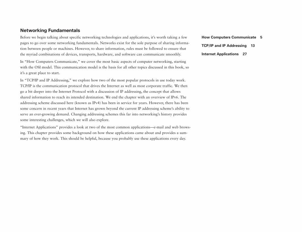
Part I: Networking Fundamentals . . . . . . . . . . . . . . . . . . . . . . . . . . . . . . . . . . . . . . . .3
How Computers Communicate . . . . . . . . . . . . . . . . . . . . . . . . . . . . . . . . . . . . . . . . . .4
The OSI Model . . . . . . . . . . . . . . . . . . . . . . . . . . . . . . . . . . . . . . . . . . . . . . . . . . . . . . . . . . . . . . . . . . .5
Open Versus Proprietary Systems . . . . . . . . . . . . . . . . . . . . . . . . . . . . . . . . . . . . . . . . . . . . . . .5
Seven Layers . . . . . . . . . . . . . . . . . . . . . . . . . . . . . . . . . . . . . . . . . . . . . . . . . . . . . . . . . . . . . . . . . . . .5
At-a-Glance: OSI Model . . . . . . . . . . . . . . . . . . . . . . . . . . . . . . . . . . . . . . . . . . . . . . . . . . . . . . .7–9
Internet Infrastructure: How It All Connects . . . . . . . . . . . . . . . . . . . . . . . . . . . . . . . . .10–11
TCP/IP and IP Addressing . . . . . . . . . . . . . . . . . . . . . . . . . . . . . . . . . . . . . . . . . . . . .12
Computers Speaking the Same Language . . . . . . . . . . . . . . . . . . . . . . . . . . . . . . . . . . . . .13
What Is an Address? . . . . . . . . . . . . . . . . . . . . . . . . . . . . . . . . . . . . . . . . . . . . . . . . . . . . . . . . . . .13
Dynamically Allocated IP Addresses . . . . . . . . . . . . . . . . . . . . . . . . . . . . . . . . . . . . . . . . . . .14
Domain Names and Relationship to IP Addresses . . . . . . . . . . . . . . . . . . . . . . . . . . . . . .14
Matching Domain Names to IP Addresses . . . . . . . . . . . . . . . . . . . . . . . . . . . . . . . . . . . . . .15
At-a-Glance: TCP/IP . . . . . . . . . . . . . . . . . . . . . . . . . . . . . . . . . . . . . . . . . . . . . . . . . . . . . . . .16–18
At-a-Glance: IP Addressing . . . . . . . . . . . . . . . . . . . . . . . . . . . . . . . . . . . . . . . . . . . . . . . . .19–21
At-a-Glance: IPv6 . . . . . . . . . . . . . . . . . . . . . . . . . . . . . . . . . . . . . . . . . . . . . . . . . . . . . . . . . . .22–24
NAT and PAT . . . . . . . . . . . . . . . . . . . . . . . . . . . . . . . . . . . . . . . . . . . . . . . . . . . . . . . . . . . . . . . . . . .25
Internet Applications . . . . . . . . . . . . . . . . . . . . . . . . . . . . . . . . . . . . . . . . . . . . . . . . . .26
The Internet and Its Applications . . . . . . . . . . . . . . . . . . . . . . . . . . . . . . . . . . . . . . . . . . . . . . .27
E-Mail . . . . . . . . . . . . . . . . . . . . . . . . . . . . . . . . . . . . . . . . . . . . . . . . . . . . . . . . . . . . . . . . . . . . . . . . . . .27
Web Browsing . . . . . . . . . . . . . . . . . . . . . . . . . . . . . . . . . . . . . . . . . . . . . . . . . . . . . . . . . . . . . . . . . .28
E-Mail . . . . . . . . . . . . . . . . . . . . . . . . . . . . . . . . . . . . . . . . . . . . . . . . . . . . . . . . . . . . . . . . . . . . . . . . . . .30
Peer-to-Peer Sharing . . . . . . . . . . . . . . . . . . . . . . . . . . . . . . . . . . . . . . . . . . . . . . . . . . . . . . . . . . .31
viii
Part III: Network Design . . . . . . . . . . . . . . . . . . . . . . . . . . . . . . . . . . . . . . . . . . . . . . .63
Campus Networks and Hierarchical Design . . . . . . . . . . . . . . . . . . . . . . . . . . . . . .64
Building Networks for Ease of Use . . . . . . . . . . . . . . . . . . . . . . . . . . . . . . . . . . . . . . . . . . . . .65
At-a-Glance: Hierarchical Campus Design . . . . . . . . . . . . . . . . . . . . . . . . . . . . . . . . . .66–69
WAN Network Design . . . . . . . . . . . . . . . . . . . . . . . . . . . . . . . . . . . . . . . . . . . . . . . . .70
Moving Traffic Across the Street and the World . . . . . . . . . . . . . . . . . . . . . . . . . . . . . . . .71
WAN Services . . . . . . . . . . . . . . . . . . . . . . . . . . . . . . . . . . . . . . . . . . . . . . . . . . . . . . . . . . . . . . . . . .71
Integrated Services Digital Network . . . . . . . . . . . . . . . . . . . . . . . . . . . . . . . . . . . . . . . . . . . .71
Frame Relay . . . . . . . . . . . . . . . . . . . . . . . . . . . . . . . . . . . . . . . . . . . . . . . . . . . . . . . . . . . . . . . . . . . .72
ATM . . . . . . . . . . . . . . . . . . . . . . . . . . . . . . . . . . . . . . . . . . . . . . . . . . . . . . . . . . . . . . . . . . . . . . . . . . . .72
MPLS . . . . . . . . . . . . . . . . . . . . . . . . . . . . . . . . . . . . . . . . . . . . . . . . . . . . . . . . . . . . . . . . . . . . . . . . . . .73
Broadband . . . . . . . . . . . . . . . . . . . . . . . . . . . . . . . . . . . . . . . . . . . . . . . . . . . . . . . . . . . . . . . . . . . . .73
Virtual Private Networks (VPN) . . . . . . . . . . . . . . . . . . . . . . . . . . . . . . . . . . . . . . . . . . . . . . . . .73
WAN Devices . . . . . . . . . . . . . . . . . . . . . . . . . . . . . . . . . . . . . . . . . . . . . . . . . . . . . . . . . . . . . . . . . . .73
At-a-Glance: Frame Relay . . . . . . . . . . . . . . . . . . . . . . . . . . . . . . . . . . . . . . . . . . . . . . . . . .74–75
At-a-Glance: Asynchronous Transfer Mode (ATM) . . . . . . . . . . . . . . . . . . . . . . . . . .76–77
Multiprotocol Label Switching (MPLS) Services . . . . . . . . . . . . . . . . . . . . . . . . . . . . . . . .78
At-a-Glance: MPLS . . . . . . . . . . . . . . . . . . . . . . . . . . . . . . . . . . . . . . . . . . . . . . . . . . . . . . . . .79–81
MPLS Traffic Separation . . . . . . . . . . . . . . . . . . . . . . . . . . . . . . . . . . . . . . . . . . . . . . . . . . . . . . . .82
Broadband Technologies . . . . . . . . . . . . . . . . . . . . . . . . . . . . . . . . . . . . . . . . . . . . . . .84
Always-on Access . . . . . . . . . . . . . . . . . . . . . . . . . . . . . . . . . . . . . . . . . . . . . . . . . . . . . . . . . . . . .85
Broadband Technology Evolution . . . . . . . . . . . . . . . . . . . . . . . . . . . . . . . . . . . . . . . . . . . . . . .85
At-a-Glance: ISDN . . . . . . . . . . . . . . . . . . . . . . . . . . . . . . . . . . . . . . . . . . . . . . . . . . . . . . . . . .87–88
At-a-Glance: Broadband . . . . . . . . . . . . . . . . . . . . . . . . . . . . . . . . . . . . . . . . . . . . . . . . . . . .89–91
Virtual Private Networks . . . . . . . . . . . . . . . . . . . . . . . . . . . . . . . . . . . . . . . . . . . . . . .92
Secure Networking Over the Internet . . . . . . . . . . . . . . . . . . . . . . . . . . . . . . . . . . . . . . . . . . .93
At-a-Glance: VPNs . . . . . . . . . . . . . . . . . . . . . . . . . . . . . . . . . . . . . . . . . . . . . . . . . . . . . . . . .95–97
Establishing a VPN Connection . . . . . . . . . . . . . . . . . . . . . . . . . . . . . . . . . . . . . . . . . . . . .98–99
At-a-Glance: Encryption . . . . . . . . . . . . . . . . . . . . . . . . . . . . . . . . . . . . . . . . . . . . . . . . . .100–102
Client Authentication . . . . . . . . . . . . . . . . . . . . . . . . . . . . . . . . . . . . . . . . . . . . . . . . . . . . .103–104
Optical Technologies . . . . . . . . . . . . . . . . . . . . . . . . . . . . . . . . . . . . . . . . . . . . . . . . .106
LANs, WANs—and Now MANs . . . . . . . . . . . . . . . . . . . . . . . . . . . . . . . . . . . . . . . . . . . . . . . .107
SONET, DWDM, and DPT . . . . . . . . . . . . . . . . . . . . . . . . . . . . . . . . . . . . . . . . . . . . . . . . . . . . . .107
At-a-Glance: Metro Optical . . . . . . . . . . . . . . . . . . . . . . . . . . . . . . . . . . . . . . . . . . . . . . .109–111
Branch Office Network Designs . . . . . . . . . . . . . . . . . . . . . . . . . . . . . . . . . . . . . . .112
Distributed Workforce . . . . . . . . . . . . . . . . . . . . . . . . . . . . . . . . . . . . . . . . . . . . . . . . . . . . . . . . .113
Distributed Office Challenges . . . . . . . . . . . . . . . . . . . . . . . . . . . . . . . . . . . . . . . . . . . . . . . . .113
At-a-Glance: Branch Office Design . . . . . . . . . . . . . . . . . . . . . . . . . . . . . . . . . . . . . . .114–117
Part IV: Network Availability . . . . . . . . . . . . . . . . . . . . . . . . . . . . . . . . . . . . . . . . . .119
High Availability . . . . . . . . . . . . . . . . . . . . . . . . . . . . . . . . . . . . . . . . . . . . . . . . . . . . .120
At-a-Glance: High Availability . . . . . . . . . . . . . . . . . . . . . . . . . . . . . . . . . . . . . . . . . . . .124–126
Control Plane . . . . . . . . . . . . . . . . . . . . . . . . . . . . . . . . . . . . . . . . . . . . . . . . . . . . . . . .128
When Good Networks Go Bad . . . . . . . . . . . . . . . . . . . . . . . . . . . . . . . . . . . . . . . . . . . . . . . .129
Control Plane Protection . . . . . . . . . . . . . . . . . . . . . . . . . . . . . . . . . . . . . . . . . . . . . . . . . . . . . .129
At-a-Glance: Control Plane Protection . . . . . . . . . . . . . . . . . . . . . . . . . . . . . . . . . . . .130–131
Quality of Service and Network Availability . . . . . . . . . . . . . . . . . . . . . . . . . . . .132
Quality of Service as Network Protection? . . . . . . . . . . . . . . . . . . . . . . . . . . . . . . . . . . . .133
Scavenger QoS . . . . . . . . . . . . . . . . . . . . . . . . . . . . . . . . . . . . . . . . . . . . . . . . . . . . . . . . . . . . . . .133
At-a-Glance: QoS for Network Resiliency . . . . . . . . . . . . . . . . . . . . . . . . . . . . . . . .134–136
Disaster Recovery . . . . . . . . . . . . . . . . . . . . . . . . . . . . . . . . . . . . . . . . . . . . . . . . . . .138
What Happens When the Network Stops Working . . . . . . . . . . . . . . . . . . . . . . . . . . . .139
DR Planning . . . . . . . . . . . . . . . . . . . . . . . . . . . . . . . . . . . . . . . . . . . . . . . . . . . . . . . . . . . . . . . . . . .139
Resiliency and Backup Services . . . . . . . . . . . . . . . . . . . . . . . . . . . . . . . . . . . . . . . . . . . . . .140
Preparedness Testing . . . . . . . . . . . . . . . . . . . . . . . . . . . . . . . . . . . . . . . . . . . . . . . . . . . . . . . . .140
At-a-Glance: Disaster Recovery: Business Continuance . . . . . . . . . . . . . . . . . .141–143
Disaster Recovery . . . . . . . . . . . . . . . . . . . . . . . . . . . . . . . . . . . . . . . . . . . . . . . . . . . . . . . . . . . .144
ix
Intrusion Prevention Systems . . . . . . . . . . . . . . . . . . . . . . . . . . . . . . . . . . . . . . . . .176
Intrusion Detection Systems . . . . . . . . . . . . . . . . . . . . . . . . . . . . . . . . . . . . . . . . . . . . . . . . . .177
Intrusion Prevention Systems . . . . . . . . . . . . . . . . . . . . . . . . . . . . . . . . . . . . . . . . . . . . . . . . .177
The Problem with False Positives . . . . . . . . . . . . . . . . . . . . . . . . . . . . . . . . . . . . . . . . . . . . .177
At-a-Glance: Intrusion Detection . . . . . . . . . . . . . . . . . . . . . . . . . . . . . . . . . . . . . . . . .178–179
Port-Based Security . . . . . . . . . . . . . . . . . . . . . . . . . . . . . . . . . . . . . . . . . . . . . . . . .180
Combating Access-Based Attacks . . . . . . . . . . . . . . . . . . . . . . . . . . . . . . . . . . . . . . . . . . . .181
At-a-Glance: Port-Based Security . . . . . . . . . . . . . . . . . . . . . . . . . . . . . . . . . . . . . . . .182–184
Identity-Based Networking . . . . . . . . . . . . . . . . . . . . . . . . . . . . . . . . . . . . . . . . . . .186
Network Access Conundrum . . . . . . . . . . . . . . . . . . . . . . . . . . . . . . . . . . . . . . . . . . . . . . . . .187
Identity-Based Networking . . . . . . . . . . . . . . . . . . . . . . . . . . . . . . . . . . . . . . . . . . . . . . . . . . . .187
802.1x . . . . . . . . . . . . . . . . . . . . . . . . . . . . . . . . . . . . . . . . . . . . . . . . . . . . . . . . . . . . . . . . . . . . . . . . .187
At-a-Glance: Identity . . . . . . . . . . . . . . . . . . . . . . . . . . . . . . . . . . . . . . . . . . . . . . . . . . . . .188–190
Authentication . . . . . . . . . . . . . . . . . . . . . . . . . . . . . . . . . . . . . . . . . . . . . . . . . . . . . . . . . . . . . . . . .191
Network Admission Control . . . . . . . . . . . . . . . . . . . . . . . . . . . . . . . . . . . . . . . . . . .192
Combating Virus Outbreaks . . . . . . . . . . . . . . . . . . . . . . . . . . . . . . . . . . . . . . . . . . . . . . . . . . .193
Assessing Device “Health” . . . . . . . . . . . . . . . . . . . . . . . . . . . . . . . . . . . . . . . . . . . . . . . . . . . .193
Network Admission Control . . . . . . . . . . . . . . . . . . . . . . . . . . . . . . . . . . . . . . . . . . . . . . . . . . .194
At-a-Glance: NAC . . . . . . . . . . . . . . . . . . . . . . . . . . . . . . . . . . . . . . . . . . . . . . . . . . . . . . . .195–197
URL Filtering: Eliminating Unwanted Web Page Access . . . . . . . . . . . . . . . . . .198
Internet Access and Liability Issues . . . . . . . . . . . . . . . . . . . . . . . . . . . . . . . . . . . . . . . . . . .199
Enforcing Corporate Internet Usage Policies . . . . . . . . . . . . . . . . . . . . . . . . . . . . . . . . . .199
At-a-Glance: URL Filtering . . . . . . . . . . . . . . . . . . . . . . . . . . . . . . . . . . . . . . . . . . . . . . .200–201
URL Filtering and Firewalls . . . . . . . . . . . . . . . . . . . . . . . . . . . . . . . . . . . . . . . . . . . . . . . . . . . .202
Deep Packet Inspection: Controlling Unwanted Applications . . . . . . . . . . . . .204
How Do You Catch a Criminal When Everyone Wears a Mask? . . . . . . . . . . . . . . .205
Deep Packet Inspection . . . . . . . . . . . . . . . . . . . . . . . . . . . . . . . . . . . . . . . . . . . . . . . . . . . . . . .205
At-a-Glance: Deep Packet Inspection . . . . . . . . . . . . . . . . . . . . . . . . . . . . . . . . . . . .206–208
Packet Inspection . . . . . . . . . . . . . . . . . . . . . . . . . . . . . . . . . . . . . . . . . . . . . . . . . . . . . . . . . . . . .209
Network Management . . . . . . . . . . . . . . . . . . . . . . . . . . . . . . . . . . . . . . . . . . . . . . .146
Keeping the Network Alive from Afar . . . . . . . . . . . . . . . . . . . . . . . . . . . . . . . . . . . . . . . . .147
Network Documentation: A Must-Have . . . . . . . . . . . . . . . . . . . . . . . . . . . . . . . . . . . . . . . .148
Network-Management Protocols . . . . . . . . . . . . . . . . . . . . . . . . . . . . . . . . . . . . . . . . . . . . . .148
Troubleshooting Tools . . . . . . . . . . . . . . . . . . . . . . . . . . . . . . . . . . . . . . . . . . . . . . . . . . . . . . . . .149
At-a-Glance: Network Management . . . . . . . . . . . . . . . . . . . . . . . . . . . . . . . . . . . . . .150–151
Network Management . . . . . . . . . . . . . . . . . . . . . . . . . . . . . . . . . . . . . . . . . . . . . . . . . . . . . . . .152
Part V: Securing the Network . . . . . . . . . . . . . . . . . . . . . . . . . . . . . . . . . . . . . . . . .155
Network Security . . . . . . . . . . . . . . . . . . . . . . . . . . . . . . . . . . . . . . . . . . . . . . . . . . . .156
Identity . . . . . . . . . . . . . . . . . . . . . . . . . . . . . . . . . . . . . . . . . . . . . . . . . . . . . . . . . . . . . . . . . . . . . . . .157
Perimeter Security . . . . . . . . . . . . . . . . . . . . . . . . . . . . . . . . . . . . . . . . . . . . . . . . . . . . . . . . . . . .157
Data Privacy . . . . . . . . . . . . . . . . . . . . . . . . . . . . . . . . . . . . . . . . . . . . . . . . . . . . . . . . . . . . . . . . . .157
Security Monitoring . . . . . . . . . . . . . . . . . . . . . . . . . . . . . . . . . . . . . . . . . . . . . . . . . . . . . . . . . . .158
Policy Enforcement . . . . . . . . . . . . . . . . . . . . . . . . . . . . . . . . . . . . . . . . . . . . . . . . . . . . . . . . . . . .158
At-a-Glance: Network Security . . . . . . . . . . . . . . . . . . . . . . . . . . . . . . . . . . . . . . . . . . .159–160
At-a-Glance: Hacking . . . . . . . . . . . . . . . . . . . . . . . . . . . . . . . . . . . . . . . . . . . . . . . . . . . . .161–163
DoS Attacks . . . . . . . . . . . . . . . . . . . . . . . . . . . . . . . . . . . . . . . . . . . . . . . . . . . . . . . . . . . . . .164–165
Snooping and Spoofing . . . . . . . . . . . . . . . . . . . . . . . . . . . . . . . . . . . . . . . . . . . . . . . . . . . . . . .166
Firewalls . . . . . . . . . . . . . . . . . . . . . . . . . . . . . . . . . . . . . . . . . . . . . . . . . . . . . . . . . . . .168
Protecting the Perimeter . . . . . . . . . . . . . . . . . . . . . . . . . . . . . . . . . . . . . . . . . . . . . . . . . . . . . .169
Get Off the Net! . . . . . . . . . . . . . . . . . . . . . . . . . . . . . . . . . . . . . . . . . . . . . . . . . . . . . . . . . . . . . . .169
Firewall for Your Protection . . . . . . . . . . . . . . . . . . . . . . . . . . . . . . . . . . . . . . . . . . . . . . . . . . .169
Personal Firewalls . . . . . . . . . . . . . . . . . . . . . . . . . . . . . . . . . . . . . . . . . . . . . . . . . . . . . . . . . . . . .170
At-a-Glance: Firewalls and IDS . . . . . . . . . . . . . . . . . . . . . . . . . . . . . . . . . . . . . . . . . . .171–172
Firewalls and IDS . . . . . . . . . . . . . . . . . . . . . . . . . . . . . . . . . . . . . . . . . . . . . . . . . . . . . . . . . . . . .173
Access and Content Security . . . . . . . . . . . . . . . . . . . . . . . . . . . . . . . . . . . . . . . . . . . . . . . . .174
x
Telemetry: Identifying and Isolating Attack Sources . . . . . . . . . . . . . . . . . . . . .210
Normal or Abnormal . . . . . . . . . . . . . . . . . . . . . . . . . . . . . . . . . . . . . . . . . . . . . . . . . . . . . . . . . . .211
Using Telemetry to Combat Attacks . . . . . . . . . . . . . . . . . . . . . . . . . . . . . . . . . . . . . . . . . . .211
At-a-Glance: Telemetry . . . . . . . . . . . . . . . . . . . . . . . . . . . . . . . . . . . . . . . . . . . . . . . . . .212–213
Physical Security: IP Video Surveillance . . . . . . . . . . . . . . . . . . . . . . . . . . . . . . .214
Locks on the Doors . . . . . . . . . . . . . . . . . . . . . . . . . . . . . . . . . . . . . . . . . . . . . . . . . . . . . . . . . . .215
Video Surveillance . . . . . . . . . . . . . . . . . . . . . . . . . . . . . . . . . . . . . . . . . . . . . . . . . . . . . . . . . . . .215
At-a-Glance: Physical Security . . . . . . . . . . . . . . . . . . . . . . . . . . . . . . . . . . . . . . . . . .216–217
Physical and Logical Security . . . . . . . . . . . . . . . . . . . . . . . . . . . . . . . . . . . . . . . . . . . . . . . . .218
Part VI: Data Centers and Application Networking . . . . . . . . . . . . . . . . . . . . . .221
Moving Data Efficiently . . . . . . . . . . . . . . . . . . . . . . . . . . . . . . . . . . . . . . . . . . . . . . . . . . . . . . . .221
Data Centers . . . . . . . . . . . . . . . . . . . . . . . . . . . . . . . . . . . . . . . . . . . . . . . . . . . . . . . .222
Store Once, Use Often . . . . . . . . . . . . . . . . . . . . . . . . . . . . . . . . . . . . . . . . . . . . . . . . . . . . . . . .223
n-Tier Model . . . . . . . . . . . . . . . . . . . . . . . . . . . . . . . . . . . . . . . . . . . . . . . . . . . . . . . . . . . . . . . . . .223
Functions and Requirements . . . . . . . . . . . . . . . . . . . . . . . . . . . . . . . . . . . . . . . . . . . . . . . . . .223
At-a-Glance: Data Centers . . . . . . . . . . . . . . . . . . . . . . . . . . . . . . . . . . . . . . . . . . . . . . .225–227
Data Center Application: Corporate Expense System . . . . . . . . . . . . . . . . . . . . . . . . .228
Storage Area Networks . . . . . . . . . . . . . . . . . . . . . . . . . . . . . . . . . . . . . . . . . . . . . .230
Efficient Deployment of Critical Data . . . . . . . . . . . . . . . . . . . . . . . . . . . . . . . . . . . . . . . . . .231
Fiber Channel and IP . . . . . . . . . . . . . . . . . . . . . . . . . . . . . . . . . . . . . . . . . . . . . . . . . . . . . . . . . .231
Infiniband . . . . . . . . . . . . . . . . . . . . . . . . . . . . . . . . . . . . . . . . . . . . . . . . . . . . . . . . . . . . . . . . . . . . .232
At-a-Glance: Storage Networking . . . . . . . . . . . . . . . . . . . . . . . . . . . . . . . . . . . . . . . .233–235
Server-Centric Storage . . . . . . . . . . . . . . . . . . . . . . . . . . . . . . . . . . . . . . . . . . . . . . . . . . . . . . .236
Caching . . . . . . . . . . . . . . . . . . . . . . . . . . . . . . . . . . . . . . . . . . . . . . . . . . . . . . . . . . . . .238
Moving Content Close to the User . . . . . . . . . . . . . . . . . . . . . . . . . . . . . . . . . . . . . . . . . . . .239
How Caching Works . . . . . . . . . . . . . . . . . . . . . . . . . . . . . . . . . . . . . . . . . . . . . . . . . . . . . . . . . .239
Caching More Than Web Pages . . . . . . . . . . . . . . . . . . . . . . . . . . . . . . . . . . . . . . . . . . . . . . .239
Storage Caching: From Disk to Memory . . . . . . . . . . . . . . . . . . . . . . . . . . . . . . . . . . . . . . .240
Issues Affecting Caching . . . . . . . . . . . . . . . . . . . . . . . . . . . . . . . . . . . . . . . . . . . . . . . . . . . . . .240
Caching . . . . . . . . . . . . . . . . . . . . . . . . . . . . . . . . . . . . . . . . . . . . . . . . . . . . . . . . . . . . . . . . . . . . . . .241
Wide Area File Services . . . . . . . . . . . . . . . . . . . . . . . . . . . . . . . . . . . . . . . . . . . . . .242
Branch Offices Rule . . . . . . . . . . . . . . . . . . . . . . . . . . . . . . . . . . . . . . . . . . . . . . . . . . . . . . . . . . .243
Centralizing Storage . . . . . . . . . . . . . . . . . . . . . . . . . . . . . . . . . . . . . . . . . . . . . . . . . . . . . . . . . .243
Enter Wide Area File Services (WAFS) . . . . . . . . . . . . . . . . . . . . . . . . . . . . . . . . . . . . . . . .243
At-a-Glance: Wide Area File Services . . . . . . . . . . . . . . . . . . . . . . . . . . . . . . . . . . .244–246
Wide Area Application Services . . . . . . . . . . . . . . . . . . . . . . . . . . . . . . . . . . . . . . .248
Centralizing Applications . . . . . . . . . . . . . . . . . . . . . . . . . . . . . . . . . . . . . . . . . . . . . . . . . . . . . .249
Enter Wide Area Application Services (WAAS) . . . . . . . . . . . . . . . . . . . . . . . . . . . . . . .249
At-a-Glance: Wide Area Application Services . . . . . . . . . . . . . . . . . . . . . . . . . . .250–252
Part VII: Unified Communications . . . . . . . . . . . . . . . . . . . . . . . . . . . . . . . . . . . . .255
Voice over IP . . . . . . . . . . . . . . . . . . . . . . . . . . . . . . . . . . . . . . . . . . . . . . . . . . . . . . . .256
Making Calls over the Web . . . . . . . . . . . . . . . . . . . . . . . . . . . . . . . . . . . . . . . . . . . . . . . . . . . .257
Unifying Communications . . . . . . . . . . . . . . . . . . . . . . . . . . . . . . . . . . . . . . . . . . . . . . . . . . . . .257
Client Layer . . . . . . . . . . . . . . . . . . . . . . . . . . . . . . . . . . . . . . . . . . . . . . . . . . . . . . . . . . . . . . . . . . .258
Infrastructure Layer . . . . . . . . . . . . . . . . . . . . . . . . . . . . . . . . . . . . . . . . . . . . . . . . . . . . . . . . . . .258
Call-Processing Layer . . . . . . . . . . . . . . . . . . . . . . . . . . . . . . . . . . . . . . . . . . . . . . . . . . . . . . . . .258
Application Layer . . . . . . . . . . . . . . . . . . . . . . . . . . . . . . . . . . . . . . . . . . . . . . . . . . . . . . . . . . . . .259
Deployment Models . . . . . . . . . . . . . . . . . . . . . . . . . . . . . . . . . . . . . . . . . . . . . . . . . . . . . . . . . . .259
At-a-Glance: Voice over IP . . . . . . . . . . . . . . . . . . . . . . . . . . . . . . . . . . . . . . . . . . . . . . .261–263
Voice over IP . . . . . . . . . . . . . . . . . . . . . . . . . . . . . . . . . . . . . . . . . . . . . . . . . . . . . . . . . . . . . . . . . .264
At-a-Glance: Unified Communications . . . . . . . . . . . . . . . . . . . . . . . . . . . . . . . . . . .265–266
Voice over IP: Toll Bypass . . . . . . . . . . . . . . . . . . . . . . . . . . . . . . . . . . . . . . . . . . . . . . . . . . . . .267
xi
IP Call Center . . . . . . . . . . . . . . . . . . . . . . . . . . . . . . . . . . . . . . . . . . . . . . . . . . . . . . .296
Why Can’t I Talk to a Real Person? . . . . . . . . . . . . . . . . . . . . . . . . . . . . . . . . . . . . . . . . . . . .297
Anatomy of a Contact Center . . . . . . . . . . . . . . . . . . . . . . . . . . . . . . . . . . . . . . . . . . . . . . . . .297
From the Caller to the Agent, and Back Again . . . . . . . . . . . . . . . . . . . . . . . . . . . . . . . . .297
Managing Caller and Contact Agent Efficiency . . . . . . . . . . . . . . . . . . . . . . . . . . . . . . . .298
New Methods for Customer Interaction . . . . . . . . . . . . . . . . . . . . . . . . . . . . . . . . . . . . . . .298
At-a-Glance: IP Contact Center . . . . . . . . . . . . . . . . . . . . . . . . . . . . . . . . . . . . . . . . . .299–300
Call-Center Tech Support . . . . . . . . . . . . . . . . . . . . . . . . . . . . . . . . . . . . . . . . . . . . . . . . . . . . .301
Call-Center Telemarketing . . . . . . . . . . . . . . . . . . . . . . . . . . . . . . . . . . . . . . . . . . . . . . . . . . . .302
Multicast and IPTV Broadcasts . . . . . . . . . . . . . . . . . . . . . . . . . . . . . . . . . . . . . . . .304
Watching Movies Without Flooding the World . . . . . . . . . . . . . . . . . . . . . . . . . . . . . . . . .305
At-a-Glance: IP Multicast . . . . . . . . . . . . . . . . . . . . . . . . . . . . . . . . . . . . . . . . . . . . . . . . .307–308
Multicast . . . . . . . . . . . . . . . . . . . . . . . . . . . . . . . . . . . . . . . . . . . . . . . . . . . . . . . . . . . . . . . . . . . . . .309
Part VIII: Mobility . . . . . . . . . . . . . . . . . . . . . . . . . . . . . . . . . . . . . . . . . . . . . . . . . . . .311
Wireless World . . . . . . . . . . . . . . . . . . . . . . . . . . . . . . . . . . . . . . . . . . . . . . . . . . . . . . . . . . . . . . . .311
Mobility and Wireless Networks . . . . . . . . . . . . . . . . . . . . . . . . . . . . . . . . . . . . . . .312
Throwing Away the Ties That Bind . . . . . . . . . . . . . . . . . . . . . . . . . . . . . . . . . . . . . . . . . . . .313
At-a-Glance: Wireless LANs . . . . . . . . . . . . . . . . . . . . . . . . . . . . . . . . . . . . . . . . . . . . .314–315
Wired LANs . . . . . . . . . . . . . . . . . . . . . . . . . . . . . . . . . . . . . . . . . . . . . . . . . . . . . . . . . . . . . . . . . . .316
Wireless LANs . . . . . . . . . . . . . . . . . . . . . . . . . . . . . . . . . . . . . . . . . . . . . . . . . . . . . . . . . . . . . . . .317
Selecting and Building Wireless Networks . . . . . . . . . . . . . . . . . . . . . . . . . . . . .318
Designing a Wireless Network . . . . . . . . . . . . . . . . . . . . . . . . . . . . . . . . . . . . . . . . . . . . . . . .319
At-a-Glance: Designing Wi-Fi Networks . . . . . . . . . . . . . . . . . . . . . . . . . . . . . . . . .320–323
Securing Wireless Networks . . . . . . . . . . . . . . . . . . . . . . . . . . . . . . . . . . . . . . . . . .324
Locking Down Wireless . . . . . . . . . . . . . . . . . . . . . . . . . . . . . . . . . . . . . . . . . . . . . . . . . . . . . . .325
Balancing Security and Access . . . . . . . . . . . . . . . . . . . . . . . . . . . . . . . . . . . . . . . . . . . . . . .325
At-a-Glance: Securing Wi-Fi . . . . . . . . . . . . . . . . . . . . . . . . . . . . . . . . . . . . . . . . . . . . .326–328
Quality of Service . . . . . . . . . . . . . . . . . . . . . . . . . . . . . . . . . . . . . . . . . . . . . . . . . . .268
Converged Networks and QoS . . . . . . . . . . . . . . . . . . . . . . . . . . . . . . . . . . . . . . . . . . . . . . .269
What Is QoS? . . . . . . . . . . . . . . . . . . . . . . . . . . . . . . . . . . . . . . . . . . . . . . . . . . . . . . . . . . . . . . . . .269
QoS and Unified Communications . . . . . . . . . . . . . . . . . . . . . . . . . . . . . . . . . . . . . . . . . . . .269
At-a-Glance: QoS . . . . . . . . . . . . . . . . . . . . . . . . . . . . . . . . . . . . . . . . . . . . . . . . . . . . . . . .271–272
How Packets Are Prioritized . . . . . . . . . . . . . . . . . . . . . . . . . . . . . . . . . . . . . . . . . . . . . . . . . .273
Unified Personal Communications . . . . . . . . . . . . . . . . . . . . . . . . . . . . . . . . . . . . .274
Too Many Communications, Too Little Time . . . . . . . . . . . . . . . . . . . . . . . . . . . . . . . . . . .275
Unify Me . . . . . . . . . . . . . . . . . . . . . . . . . . . . . . . . . . . . . . . . . . . . . . . . . . . . . . . . . . . . . . . . . . . . . .275
Cisco Unified Personal Communicator (CUPC) . . . . . . . . . . . . . . . . . . . . . . . . . . . . . . . .275
At-a-Glance: Unified Communications . . . . . . . . . . . . . . . . . . . . . . . . . . . . . . . . . . .276–277
Meeting Collaboration Spaces . . . . . . . . . . . . . . . . . . . . . . . . . . . . . . . . . . . . . . . .278
Meetings, Meetings, Meetings . . . . . . . . . . . . . . . . . . . . . . . . . . . . . . . . . . . . . . . . . . . . . . . .279
Meetings Are an Activity, Not a Place . . . . . . . . . . . . . . . . . . . . . . . . . . . . . . . . . . . . . . . . .279
At-a-Glance: Meeting Collaboration . . . . . . . . . . . . . . . . . . . . . . . . . . . . . . . . . . . . .280–281
Traditional Videoconferencing . . . . . . . . . . . . . . . . . . . . . . . . . . . . . . . . . . . . . . . .282
I See You . . . . . . . . . . . . . . . . . . . . . . . . . . . . . . . . . . . . . . . . . . . . . . . . . . . . . . . . . . . . . . . . . . . . . .283
Video over IP Networks . . . . . . . . . . . . . . . . . . . . . . . . . . . . . . . . . . . . . . . . . . . . . . . . . . . . . . .283
At-a-Glance: IP Videoconferencing . . . . . . . . . . . . . . . . . . . . . . . . . . . . . . . . . . . . . .284–285
Videoconferencing . . . . . . . . . . . . . . . . . . . . . . . . . . . . . . . . . . . . . . . . . . . . . . . . . . . . . . . . . . . .286
Videoconferencing Application E-Learning . . . . . . . . . . . . . . . . . . . . . . . . . . . . . . . . . . . .287
Telepresence . . . . . . . . . . . . . . . . . . . . . . . . . . . . . . . . . . . . . . . . . . . . . . . . . . . . . . . .288
Conferencing Gets Simple . . . . . . . . . . . . . . . . . . . . . . . . . . . . . . . . . . . . . . . . . . . . . . . . . . . .289
Video Killed the Radio Star . . . . . . . . . . . . . . . . . . . . . . . . . . . . . . . . . . . . . . . . . . . . . . . . . . . .289
The Next-Best Thing to Being There . . . . . . . . . . . . . . . . . . . . . . . . . . . . . . . . . . . . . . . . . .289
At-a-Glance: Telepresence . . . . . . . . . . . . . . . . . . . . . . . . . . . . . . . . . . . . . . . . . . . . . .290–291
Presence and Location-Aware Services . . . . . . . . . . . . . . . . . . . . . . . . . . . . . . . .292
I Sense a Presence . . . . . . . . . . . . . . . . . . . . . . . . . . . . . . . . . . . . . . . . . . . . . . . . . . . . . . . . . . .293
The Importance of Location . . . . . . . . . . . . . . . . . . . . . . . . . . . . . . . . . . . . . . . . . . . . . . . . . . .293
At-a-Glance: Presence and Location-Aware Services . . . . . . . . . . . . . . . . . . .294–295
xii
Outdoor and Municipal Wireless Networks . . . . . . . . . . . . . . . . . . . . . . . . . . . . .330
It’s Just Like a Building, Only Way Bigger . . . . . . . . . . . . . . . . . . . . . . . . . . . . . . . . . . . . .331
At-a-Glance: Municipal Wi-Fi . . . . . . . . . . . . . . . . . . . . . . . . . . . . . . . . . . . . . . . . . . . . .332–334
VoIP over Wireless Networks . . . . . . . . . . . . . . . . . . . . . . . . . . . . . . . . . . . . . . . . .336
Wireless VoIP . . . . . . . . . . . . . . . . . . . . . . . . . . . . . . . . . . . . . . . . . . . . . . . . . . . . . . . . . . . . . . . . .337
At-a-Glance: Wireless VoIP . . . . . . . . . . . . . . . . . . . . . . . . . . . . . . . . . . . . . . . . . . . . . .338–339
Wireless VoIP . . . . . . . . . . . . . . . . . . . . . . . . . . . . . . . . . . . . . . . . . . . . . . . . . . . . . . . . . . . . . . . . .340
Wireless Guest Access . . . . . . . . . . . . . . . . . . . . . . . . . . . . . . . . . . . . . . . . . . . . . . .342
Mi Casa Es Su Casa . . . . . . . . . . . . . . . . . . . . . . . . . . . . . . . . . . . . . . . . . . . . . . . . . . . . . . . . . . .343
At-a-Glance: Wireless Guest Access . . . . . . . . . . . . . . . . . . . . . . . . . . . . . . . . . . . .344–345
RFID and Location-Based Services . . . . . . . . . . . . . . . . . . . . . . . . . . . . . . . . . . . .346
Finding Your Stuff . . . . . . . . . . . . . . . . . . . . . . . . . . . . . . . . . . . . . . . . . . . . . . . . . . . . . . . . . . . . .347
Wireless LANS: They’re Not Just for Checking E-Mail on the Toilet Anymore! .347
At-a-Glance: Location-Based Services . . . . . . . . . . . . . . . . . . . . . . . . . . . . . . . . . .348–350
Wireless Location Services . . . . . . . . . . . . . . . . . . . . . . . . . . . . . . . . . . . . . . . . . . . . . . . . . . .351
Part IX: Virtualized Networks . . . . . . . . . . . . . . . . . . . . . . . . . . . . . . . . . . . . . . . . .353
Virtualizing Data Centers . . . . . . . . . . . . . . . . . . . . . . . . . . . . . . . . . . . . . . . . . . . . .354
Growth of the Data Center . . . . . . . . . . . . . . . . . . . . . . . . . . . . . . . . . . . . . . . . . . . . . . . . . . . .355
Data Center Virtualization . . . . . . . . . . . . . . . . . . . . . . . . . . . . . . . . . . . . . . . . . . . . . . . . . . . . .355
At-a-Glance: Virtual Data Centers . . . . . . . . . . . . . . . . . . . . . . . . . . . . . . . . . . . . . . . .356–358
Virtualizing Network Infrastructure . . . . . . . . . . . . . . . . . . . . . . . . . . . . . . . . . . . .360
Leveraging Network Investment . . . . . . . . . . . . . . . . . . . . . . . . . . . . . . . . . . . . . . . . . . . . . .361
A Network Is a Network . . . . . . . . . . . . . . . . . . . . . . . . . . . . . . . . . . . . . . . . . . . . . . . . . . . . . . .361
Virtualizing Network Infrastructure . . . . . . . . . . . . . . . . . . . . . . . . . . . . . . . . . . . . . . . . . . . .361
At-a-Glance: Virtual Network Infrastructure . . . . . . . . . . . . . . . . . . . . . . . . . . . . . .362–365
Applications of Virtualized Networks . . . . . . . . . . . . . . . . . . . . . . . . . . . . . . . . . .366
What Can You Do with Virtualized Networks? . . . . . . . . . . . . . . . . . . . . . . . . . . . . . . . . .367
Corporate Employee “Clean” and “Dirty” Networks . . . . . . . . . . . . . . . . . . . . . . . . . . .367
Guest and Partner Networks . . . . . . . . . . . . . . . . . . . . . . . . . . . . . . . . . . . . . . . . . . . . . . . . . .367
Isolating Specialized Devices and Applications . . . . . . . . . . . . . . . . . . . . . . . . . . . . . . .367
Load Balancing . . . . . . . . . . . . . . . . . . . . . . . . . . . . . . . . . . . . . . . . . . . . . . . . . . . . . . . . . . . . . . . .367
Providing Hosted Networks to Entities Within Entities . . . . . . . . . . . . . . . . . . . . . . . . .367
Departmental Virtual Networks . . . . . . . . . . . . . . . . . . . . . . . . . . . . . . . . . . . . . . . . . . . . . . .368
Challenges with Virtual Networks . . . . . . . . . . . . . . . . . . . . . . . . . . . . . . . . . . . . . . . . . . . . .368
At-a-Glance: Virtualized Network Applications . . . . . . . . . . . . . . . . . . . . . . . . . .369–372
Evolution of Virtual Networks . . . . . . . . . . . . . . . . . . . . . . . . . . . . . . . . . . . . . . . . . . . .373–374
Index . . . . . . . . . . . . . . . . . . . . . . . . . . . . . . . . . . . . . . . . . . . . . . . . . . . . . . . . . . . . . . .376
xiii
Introduction
Welcome, and thank you for taking a look at this book! Unlike the vast array of network-
ing books written by geeks for geeks, this book was written for you and for anyone who
wants to understand the computer networking phenomenon that has taken the world by
storm. (In other words, it’s by geeks for nongeeks.) We understand that the vast majority of
people working in this industry are not networking experts and that it is difficult to under-
stand complex technical and business issues before knowing the answers to such questions
as “How does the web work?,” “What is a router?,” and “What is an IP address?”
Whether you are a home computer user who has just purchased a broadband Internet con-
nection or a company executive who wants to understand what your IT staff is talking
about, this book is for you.
If you’ve decided that you want to make a career change, or if you are in school pursuing a
Cisco certification, we believe that this book will serve both as a good primer, introducing
the concepts of networking in clear and simple terms, and as a useful reference book as you
grow in your career.
What’s New in This Edition?
Five years ago, when Paul Della Maggiora and Jim Doherty wrote the first edition, we were
trying to fill a gap in the market with a book that explained a broad selection of network-
ing technologies and concepts for the beginner or nontechnical person. Upon sharing our
early work, we realized we might be on to something. More talks with college interns,
Cisco Academy students, and nontechnical executives at Cisco customers indicated demand
for a show-me-what-it-is type of book. This book provides at-a-glance text and illustrations
that explain a particular concept or technology in plain and simple language. The material
illustrates how these concepts relate to our everyday lives.
We are pleased with the reception the book has received since it was first published. We
have received a great deal of positive feedback both from our intended audience and, much
to our surprise, from very technical people as well. In fact, the book has had enough inter-
est that we were approached to write a second edition to cover all the new technologies that
have come about in the last five years. After all was said and done, about half of this book
ended up being new.
Among the biggest additions to this version are the topics covering security, communication
tools, and wireless technologies. Security has become one of the biggest areas of investment
for networking as companies attempt to protect their network and data from ever-increasing
threats and attacks. Communication tools have also changed quite a bit in five years, as
both voice and video tools have become more integrated and more sophisticated. Finally,
wireless is everywhere now, and users expect all the networking tools on the wired network
to be on the wireless network as well.
Another change in this book is that Neil Anderson has joined the writing team. Neil is the
coauthor of four other Networking Simplified books that we have written since the original
release of Cisco Networking Simplified. Neil is a great addition to the team and brings a
wealth of expertise and insight to this edition.
So How Do I Use This Thing?
The book is divided into nine theme-based parts, each with several chapters covering a network
concept or technology. Each chapter contains some or all of the following: a part summary,
topic at-a-glance pages, and whiteboard illustrations of relevant concepts. The part summary
provides a quick and easy introduction to the topic, so you should generally read it first.
Useful for future reference are the topic at-a-glance pages, which illustrate core concepts.
And the whiteboard illustrations demonstrate important concepts simply and graphically.
The flow of this book is a bit different from the first time around. In this edition, we took a
building-block approach:
• Part I: Networking Fundamentals
• Part II: Networking Infrastructure
• Part III: Network Design
• Part IV: Network Availability
• Part V: Securing the Network
• Part VI: Data Center and Application Networking
• Part VII: Unified Communications
• Part VIII: Mobility
• Part IX: Virtualized Networks

xiv
We believe that this approach helps you get from the basics to the more advanced topics
more easily. This approach also makes it easier to jump directly into a single topic of interest
and understand the big picture.
The illustrations and descriptions of the topics serve to answer the primary questions “What
is it?”, “Why should I care?”, and “What problems need to be solved?”. We use “big ani-
mal” pictures to explain many of the concepts and avoid the temptation to dive into nitty-
gritty details. If you are reading this book, you need to know, for example, what a router
does, but not how to actually program one.
The second time around, we had as much fun as the first time through writing and illustrat-
ing this book. We also had the benefit of experience and are hopeful that we put it to good
use. We hope you find this book both useful and entertaining. If it ends up being your pri-
mary reference for networking, so much the better.

This page intentionally left blank
Part I
Networking FundamentalsBefore we begin talking about specific networking technologies and applications, it’s worth taking a few
pages to go over some networking fundamentals. Networks exist for the sole purpose of sharing informa-
tion between people or machines. However, to share information, rules must be followed to ensure that
the myriad combinations of devices, transports, hardware, and software can communicate smoothly.
In “How Computers Communicate,” we cover the most basic aspects of computer networking, starting
with the OSI model. This communication model is the basis for all other topics discussed in this book, so
it’s a great place to start.
In “TCP/IP and IP Addressing,” we explore how two of the most popular protocols in use today work.
TCP/IP is the communication protocol that drives the Internet as well as most corporate traffic. We then
go a bit deeper into the Internet Protocol with a discussion of IP addressing, the concept that allows
shared information to reach its intended destination. We end the chapter with an overview of IPv6. The
addressing scheme discussed here (known as IPv4) has been in service for years. However, there has been
some concern in recent years that Internet has grown beyond the current IP addressing scheme’s ability to
serve an ever-growing demand. Changing addressing schemes this far into networking’s history provides
some interesting challenges, which we will also explore.
“Internet Applications” provides a look at two of the most common applications—e-mail and web brows-
ing. This chapter provides some background on how these applications came about and provides a sum-
mary of how they work. This should be helpful, because you probably use these applications every day.
How Computers Communicate 5
TCP/IP and IP Addressing 13
Internet Applications 27
How Computers Communicate
Open Versus Proprietary SystemsAlthough the open-source model is well-known today, when the OSI model was
being developed, there was an ongoing struggle to balance technical openness
with competitive advantage. At that time, each individual network equipment
vendor saw it as an advantage to develop technologies that other companies
could not copy or interact with. Proprietary systems let a vendor claim com-
petitive advantage as well as collect fees from other vendors it might choose to
share the technology with.
However, proprietary systems can complicate the network administrator’s job
by locking him or her into one vendor, reducing competitiveness and allowing
the vendor to charge higher prices. If the vendor goes out of business or aban-
dons the technology, no one is left to support or enhance the technology.
The alternative is an open-systems approach in which standards bodies, such
as the Institute of Electrical and Electronic Engineers (IEEE) or ISO, define
technologies. Ethernet, Transmission Control Protocol/Internet Protocol
(TCP/IP), and Spanning Tree Protocol (STP) are examples of technologies that
became standards. Today it is almost impossible to gain market traction with a
product that does not at least allow an open interface for other vendors to
work with. Any network-equipment vendor can implement an open standard.
Seven LayersThe following list outlines the seven layers of the OSI model from the bottom up:
• Layer 1, physical: The physical layer is responsible for converting a frame
(the output from Layer 2) into electrical signals to be transmitted over the
network. The actual physical network can be copper wiring, optical fiber,
wireless radio signals, or any other medium that can carry signals. (We often
joke about running networks over barbed wire. It’s just a joke, but it actual-
ly can be done.) This layer also provides a method for the receiving device
to validate that the data was not corrupted during transmission.
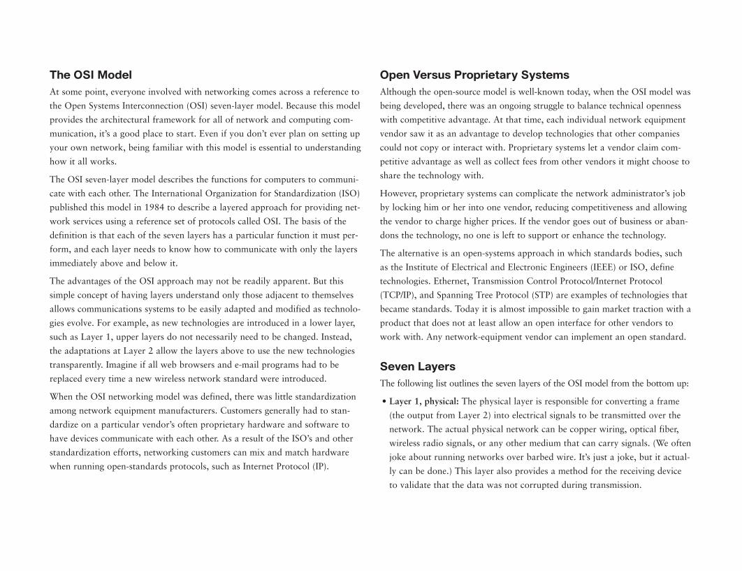
The OSI ModelAt some point, everyone involved with networking comes across a reference to
the Open Systems Interconnection (OSI) seven-layer model. Because this model
provides the architectural framework for all of network and computing com-
munication, it’s a good place to start. Even if you don’t ever plan on setting up
your own network, being familiar with this model is essential to understanding
how it all works.
The OSI seven-layer model describes the functions for computers to communi-
cate with each other. The International Organization for Standardization (ISO)
published this model in 1984 to describe a layered approach for providing net-
work services using a reference set of protocols called OSI. The basis of the
definition is that each of the seven layers has a particular function it must per-
form, and each layer needs to know how to communicate with only the layers
immediately above and below it.
The advantages of the OSI approach may not be readily apparent. But this
simple concept of having layers understand only those adjacent to themselves
allows communications systems to be easily adapted and modified as technolo-
gies evolve. For example, as new technologies are introduced in a lower layer,
such as Layer 1, upper layers do not necessarily need to be changed. Instead,
the adaptations at Layer 2 allow the layers above to use the new technologies
transparently. Imagine if all web browsers and e-mail programs had to be
replaced every time a new wireless network standard were introduced.
When the OSI networking model was defined, there was little standardization
among network equipment manufacturers. Customers generally had to stan-
dardize on a particular vendor’s often proprietary hardware and software to
have devices communicate with each other. As a result of the ISO’s and other
standardization efforts, networking customers can mix and match hardware
when running open-standards protocols, such as Internet Protocol (IP).
6 • Networking Fundamentals
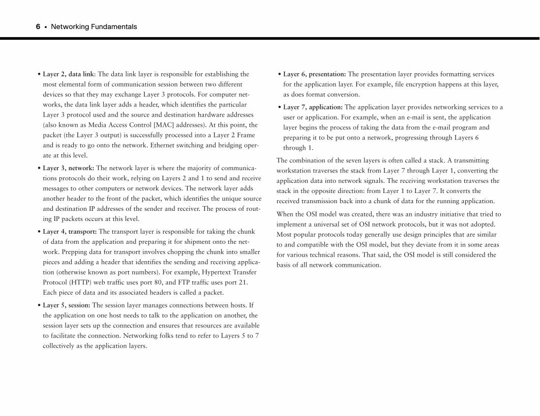
• Layer 2, data link: The data link layer is responsible for establishing the
most elemental form of communication session between two different
devices so that they may exchange Layer 3 protocols. For computer net-
works, the data link layer adds a header, which identifies the particular
Layer 3 protocol used and the source and destination hardware addresses
(also known as Media Access Control [MAC] addresses). At this point, the
packet (the Layer 3 output) is successfully processed into a Layer 2 Frame
and is ready to go onto the network. Ethernet switching and bridging oper-
ate at this level.
• Layer 3, network: The network layer is where the majority of communica-
tions protocols do their work, relying on Layers 2 and 1 to send and receive
messages to other computers or network devices. The network layer adds
another header to the front of the packet, which identifies the unique source
and destination IP addresses of the sender and receiver. The process of rout-
ing IP packets occurs at this level.
• Layer 4, transport: The transport layer is responsible for taking the chunk
of data from the application and preparing it for shipment onto the net-
work. Prepping data for transport involves chopping the chunk into smaller
pieces and adding a header that identifies the sending and receiving applica-
tion (otherwise known as port numbers). For example, Hypertext Transfer
Protocol (HTTP) web traffic uses port 80, and FTP traffic uses port 21.
Each piece of data and its associated headers is called a packet.
• Layer 5, session: The session layer manages connections between hosts. If
the application on one host needs to talk to the application on another, the
session layer sets up the connection and ensures that resources are available
to facilitate the connection. Networking folks tend to refer to Layers 5 to 7
collectively as the application layers.
• Layer 6, presentation: The presentation layer provides formatting services
for the application layer. For example, file encryption happens at this layer,
as does format conversion.
• Layer 7, application: The application layer provides networking services to a
user or application. For example, when an e-mail is sent, the application
layer begins the process of taking the data from the e-mail program and
preparing it to be put onto a network, progressing through Layers 6
through 1.
The combination of the seven layers is often called a stack. A transmitting
workstation traverses the stack from Layer 7 through Layer 1, converting the
application data into network signals. The receiving workstation traverses the
stack in the opposite direction: from Layer 1 to Layer 7. It converts the
received transmission back into a chunk of data for the running application.
When the OSI model was created, there was an industry initiative that tried to
implement a universal set of OSI network protocols, but it was not adopted.
Most popular protocols today generally use design principles that are similar
to and compatible with the OSI model, but they deviate from it in some areas
for various technical reasons. That said, the OSI model is still considered the
basis of all network communication.
How Computers Communicate • 7
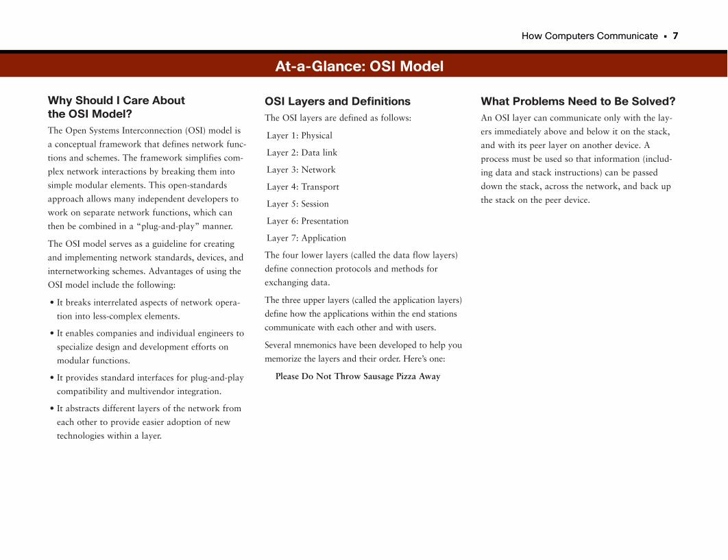
Why Should I Care About the OSI Model?The Open Systems Interconnection (OSI) model is
a conceptual framework that defines network func-
tions and schemes. The framework simplifies com-
plex network interactions by breaking them into
simple modular elements. This open-standards
approach allows many independent developers to
work on separate network functions, which can
then be combined in a “plug-and-play” manner.
The OSI model serves as a guideline for creating
and implementing network standards, devices, and
internetworking schemes. Advantages of using the
OSI model include the following:
• It breaks interrelated aspects of network opera-
tion into less-complex elements.
• It enables companies and individual engineers to
specialize design and development efforts on
modular functions.
• It provides standard interfaces for plug-and-play
compatibility and multivendor integration.
• It abstracts different layers of the network from
each other to provide easier adoption of new
technologies within a layer.
What Problems Need to Be Solved?An OSI layer can communicate only with the lay-
ers immediately above and below it on the stack,
and with its peer layer on another device. A
process must be used so that information (includ-
ing data and stack instructions) can be passed
down the stack, across the network, and back up
the stack on the peer device.
OSI Layers and DefinitionsThe OSI layers are defined as follows:
Layer 1: Physical
Layer 2: Data link
Layer 3: Network
Layer 4: Transport
Layer 5: Session
Layer 6: Presentation
Layer 7: Application
The four lower layers (called the data flow layers)
define connection protocols and methods for
exchanging data.
The three upper layers (called the application layers)
define how the applications within the end stations
communicate with each other and with users.
Several mnemonics have been developed to help you
memorize the layers and their order. Here’s one:
Please Do Not Throw Sausage Pizza Away
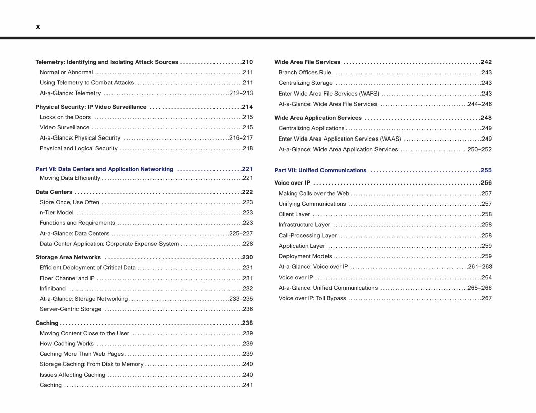
At-a-Glance: OSI Model
Application
Presentation
Session
Transport
Network
Data Link
Physical
Layer 7
Layer 6
Layer 5
Layer 4
Layer 3
Layer 2
Layer 1
TelnetHTTP
JPEGASCII7
OSScheduling
TCPUDP
IPIPX
802/3HDLC
EIA/TIA -232V.35
User Interface
Encryption and Other Processing
Manages Multiple Applications
Provides Reliable and UnreliableDelivery and Error Correction
Provides Logical AddressingUsed by Routers
Access Endpoints with MAC Address Error Detection Correction
Specifies Voltage, Wire Speed,and Pin-Out Cables
Layer Name
Cabling
Switches
Routers
Frame
Segment
Packet
Layer No. Function Examples
Encapsulation De-Encapsulation
Data
Data
Data
Data
Data
LLC Header
IP Header
TCP Header
MAC Header
FCS
FCS
1100101011010
Data
Data
Data
Data
Data
LLC Header
IP Header
TCP Header
MAC Header
FCS
FCS
1100101011010
8 • Networking Fundamentals
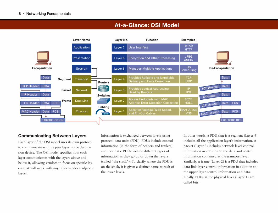
Communicating Between LayersEach layer of the OSI model uses its own protocol
to communicate with its peer layer in the destina-
tion device. The OSI model specifies how each
layer communicates with the layers above and
below it, allowing vendors to focus on specific lay-
ers that will work with any other vendor’s adjacent
layers.
Information is exchanged between layers using
protocol data units (PDU). PDUs include control
information (in the form of headers and trailers)
and user data. PDUs include different types of
information as they go up or down the layers
(called “the stack”). To clarify where the PDU is
on the stack, it is given a distinct name at each of
the lower levels.
At-a-Glance: OSI Model
In other words, a PDU that is a segment (Layer 4)
includes all the application layer’s information. A
packet (Layer 3) includes network layer control
information in addition to the data and control
information contained at the transport layer.
Similarly, a frame (Layer 2) is a PDU that includes
data link layer control information in addition to
the upper layer control information and data.
Finally, PDUs at the physical layer (Layer 1) are
called bits.
How Computers Communicate • 9
EncapsulationThe process of passing data down the stack using
PDUs is called data encapsulation. Encapsulation
works as follows: When a layer receives a PDU
from the layer above it, it encapsulates the PDU
with a header and trailer and then passes the PDU
down to the next layer. The control information
that is added to the PDU is read by the peer layer
on the remote device. Think of this as like putting
a letter in an envelope, which has the destination
address on it. The envelope is then put in a mail-
bag with a zip code on it. The bag is then placed in
large box with a city name on it. The box is then
put on a plane for transport to the city.
Extra Layers?Discussions among technical purists can often lead
to philosophical or budgetary debates that can
quickly derail otherwise-productive meetings.
These discussions are often referred to as Layer 8
(political) and Layer 9 (financial) debates.
Although these layers are not really part of the
OSI model, they are usually the underlying cause
of heated technology arguments.
Another common joke among networking profes-
sionals is the type of networking problem referred
to as a “Layer 8 issue.” Because the network, com-
puters, and applications stop at Layer 7, Layer 8
sometimes represents the end user actually using
the system. So if you hear your IT person snicker
to his colleagues that your IT trouble ticket is
closed and it was a “Layer 8 issue,” the IT person
is referring to you.
De-encapsulationDe-encapsulation, the opposite of encapsulation, is
the process of passing information up the stack.
When a layer receives a PDU from the layer below,
it does the following:
1. It reads the control information provided by
the peer source device.
2. The layer strips the control information
(header) from the frame.
3. It processes the data (usually passing it up the
stack).
Each subsequent layer performs this same de-
encapsulation process. To continue the preceding
example, when the plane arrives, the box of mail is
removed from the plane. The mailbags are taken
out of the boxes and are sent to the correct post
office. The letters are removed from the mailbags
and are delivered to the correct address. The
intended recipient opens the envelope and reads
the letter.
At-a-Glance: OSI Model
Your PC
ChinaTours.com
DNS
Local ISP
Local ISP
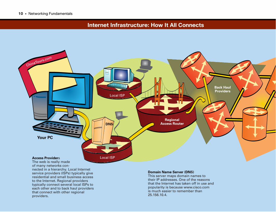
Access ProvidersThe web is really madeof many networks con-nected in a hierarchy. Local Internetservice providers (ISPs) typically giveresidential and small business accessto the Internet. Regional providerstypically connect several local ISPs toeach other and to back haul providersthat connect with other regionalproviders.
RegionalAccess Router
Domain Name Server (DNS)This server maps domain names totheir IP addresses. One of the reasonsthat the Internet has taken off in use andpopularity is because www.cisco.comis much easier to remember than25.156.10.4.
Back HaulProviders
Internet Infrastructure: How It All Connects
10 • Networking Fundamentals
How Computers Communicate • 11
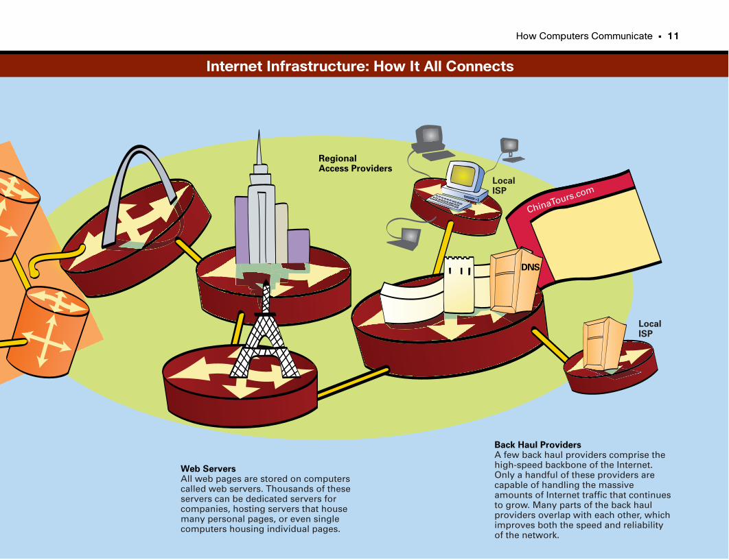
ChinaTours.com
DNS
Web ServersAll web pages are stored on computerscalled web servers. Thousands of theseservers can be dedicated servers forcompanies, hosting servers that housemany personal pages, or even singlecomputers housing individual pages.
LocalISP
Back Haul ProvidersA few back haul providers comprise thehigh-speed backbone of the Internet.Only a handful of these providers arecapable of handling the massiveamounts of Internet traffic that continuesto grow. Many parts of the back haulproviders overlap with each other, whichimproves both the speed and reliabilityof the network.
RegionalAccess Providers
LocalISP
Internet Infrastructure: How It All Connects
TCP/IP and IP Addressing
Computers Speaking the Same LanguageThe Internet protocols comprise the most popular, nonproprietary data-networking
protocol suite in the world. The Internet protocols are communication protocols
used by electronic devices to talk to each other. Initially, computers were the
primary clients of IP protocols, but other types of electronic devices can con-
nect to IP networks, including printers, cellular phones, and MP3 players.
Today, even common devices such as vending machines, dishwashers, and cars
are being connected to IP networks.
The two best-known Internet protocols are Transmission Control Protocol
(TCP) and Internet Protocol (IP). The Defense Advanced Research Projects
Agency (DARPA) developed the Internet protocols in the mid-1970s. DARPA
funded Stanford University and Bolt, Beranek, and Newman (BBN) to develop
a set of protocols that would allow different types of computers at various
research locations to communicate over a common packet-switched network.
The result of this research produced the Internet protocol suite, which was
later distributed for free with the Berkeley Software Distribution (BSD) UNIX
operating system.
From there, IP became the primary networking protocol, serving as the basis
for the World Wide Web (WWW) and the Internet in general. Internet proto-
cols are discussed and adopted in the public domain. Technical bulletins called
Requests for Comments (RFC) documents proposed protocols and practices.
These documents are reviewed, edited, published, and analyzed, and then are
accepted by the Internet community (this process takes years).
The Internet protocol suite also comprises application-based protocols, includ-
ing definitions for the following:
• Electronic mail (Simple Mail Transfer Protocol [SMTP])
• Terminal emulation (Telnet)
• File transfer (File Transfer Protocol [FTP])
• HTTP
IP is considered a Layer 3 protocol according to the OSI model, and TCP is a
Layer 4 protocol.
What Is an Address?For computers to send and receive information to each other, they must have
some form of addressing so that each end device on the network knows what
information to read and what information to ignore. This capability is impor-
tant both for the computers that ultimately use the information and for the
devices that deliver information to end stations, such as switches and routers.
Every computer on a network has two addresses:
• MAC address: A manufacturer-allocated ID number (such as a global serial
number) that is permanent and unique to every network device on Earth.
MAC addresses are analogous to a social security number or other national
identification number. You have only one, it stays the same wherever you go,
and no two people (devices) have the same number. MAC address are for-
matted using six pairs of hexadecimal numbers, such as 01-23-45-67-89-AB.
Hexadecimal or “hex” is a base 16 numbering scheme that uses the num-
bers 0 through 9 and the letters A through F to count from 0 to 15. This
might seem odd, but it provides an easy translation from binary (which uses
only 1s and 0s), which is the language of all computers.
• IP address: This address is what matters most to basic networking. Unlike a
MAC address, the IP address of any device is temporary and can be
changed. It is often assigned by the network itself and is analogous to your
street address. It only needs to be unique within a network. Someone else’s
network might use the same IP address, much like another town might have
the same street (for example, 101 Main Street). Every device on an IP net-
work is given an IP address, which looks like this: 192.168.1.100.
The format of this address is called dotted-decimal notation. The period sepa-
rators are pronounced “dot,” as in one ninety two dot one sixty eight dot....”
Because of some rules with binary, the largest number in each section is 255.
In addition to breaking up the number, the dots that appear in IP addresses
allow us to break the address into parts that represent networks and hosts. In
this case, the “network” portion refers to a company, university, government
agency, or your private network. The hosts would be the addresses of all the
computers on the individual network. If you think of the network portion of
14 • Networking Fundamentals
the address as a street, the hosts would be all the houses on that street. If you
could see the IP addresses of everyone who is on the same network segment as
you, you would notice that the network portion of the address is the same for
all computers, and the host portion changes from computer to computer. An
example will probably help. Think of an IP address as being like your home
address for the post office: state.city.street.house-number.
Each number in the IP address provides a more and more specific location so
that the Internet can find your computer among millions of other computers.
The Internet is not organized geographically like the postal system, though.
The components of the address (intentionally oversimplified) are major-
network.minor-network.local-network.device.
Dynamically Allocated IP AddressesA network administrator is responsible for assigning which devices receive
which IP addresses in a corporate network. The admin assigns an IP address to
a device in one of two ways: by configuring the device with a specific address
or by letting the device automatically learn its address from the network.
Dynamic Host Configuration Protocol (DHCP) is the protocol used for auto-
matic IP address assignment. Dynamic addressing saves considerable adminis-
trative effort and conserves IP addressing space. It can be difficult to manually
administer IP addresses for every computer and device on a network. Most
networks use DHCP to automatically assign an available IP address to a device
when it connects to the network. Generally, devices that don’t move around
receive fixed addresses, known as static addressing. For example, servers,
routers, and switches usually receive static IP addresses. The rest use dynamic
addressing. For home networks you do not need a network administrator to
set up your address; instead, a home broadband router allocates IP addresses
via DHCP.
Domain Names and Relationship to IP AddressesBecause IP addresses are difficult to remember in their dotted-decimal nota-
tion, a naming convention called domain names was established that’s more
natural for people to use. Domain names such as www.cisco.com are regis-
tered and associated with a particular public IP address. The Domain Name
System (DNS) maps a readable name to an IP address. For example, when you
enter http://www.cisco.com into a browser, the PC uses the DNS protocol to
contact a DNS name server. The name server translates the name
http://www.cisco.com into the actual IP address for that host..
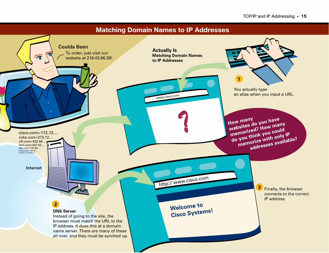
TCP/IP and IP Addressing • 15
To order, just visit our website at 216.43.96.26!
Coulda Been
Internet
1
2
3
You actually type an alias when you input a URL.
www.cisco.com
How many
websites do you have
memorized? How many
do you think you could
memorize with only IP
addresses available?
Actually IsMatching Domain Names
to IP Addresses
DNS Server
Instead of going to the site, the browser must match the URL to the IP address. It does this at a domainname server. There are many of these all over, and they must be synched up.
cisco.com=172.13…coke.com=273.12…nfl.com=432.56…ibm.com=347.52…nbc.com=137.86…fritos.com=753.21…wendys.com=691.47…
Finally, the browser connects to the correct IP address.
http:// www.cisco.com
Welcome to
Cisco Systems!
Matching Domain Names to IP Addresses
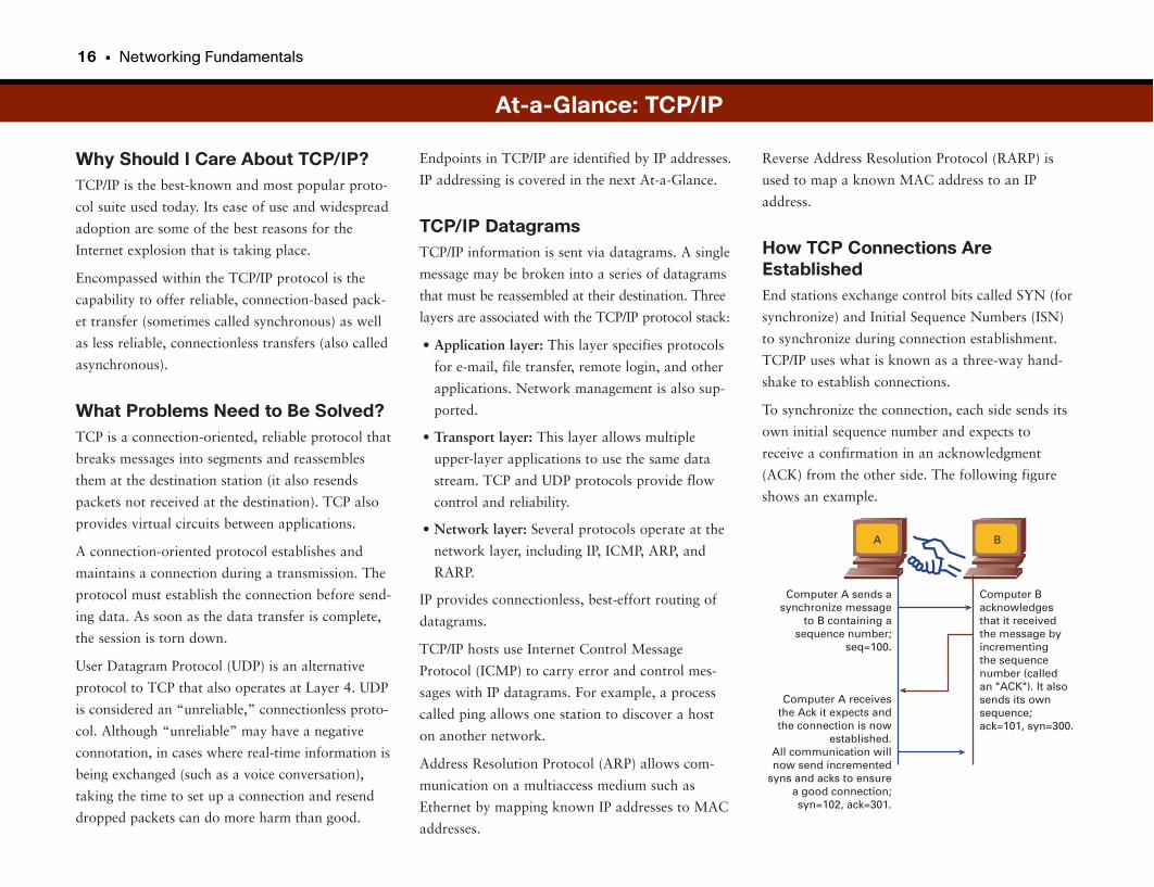
16 • Networking Fundamentals
Why Should I Care About TCP/IP?TCP/IP is the best-known and most popular proto-
col suite used today. Its ease of use and widespread
adoption are some of the best reasons for the
Internet explosion that is taking place.
Encompassed within the TCP/IP protocol is the
capability to offer reliable, connection-based pack-
et transfer (sometimes called synchronous) as well
as less reliable, connectionless transfers (also called
asynchronous).
What Problems Need to Be Solved?TCP is a connection-oriented, reliable protocol that
breaks messages into segments and reassembles
them at the destination station (it also resends
packets not received at the destination). TCP also
provides virtual circuits between applications.
A connection-oriented protocol establishes and
maintains a connection during a transmission. The
protocol must establish the connection before send-
ing data. As soon as the data transfer is complete,
the session is torn down.
User Datagram Protocol (UDP) is an alternative
protocol to TCP that also operates at Layer 4. UDP
is considered an “unreliable,” connectionless proto-
col. Although “unreliable” may have a negative
connotation, in cases where real-time information is
being exchanged (such as a voice conversation),
taking the time to set up a connection and resend
dropped packets can do more harm than good.
Reverse Address Resolution Protocol (RARP) is
used to map a known MAC address to an IP
address.
How TCP Connections AreEstablishedEnd stations exchange control bits called SYN (for
synchronize) and Initial Sequence Numbers (ISN)
to synchronize during connection establishment.
TCP/IP uses what is known as a three-way hand-
shake to establish connections.
To synchronize the connection, each side sends its
own initial sequence number and expects to
receive a confirmation in an acknowledgment
(ACK) from the other side. The following figure
shows an example.
Endpoints in TCP/IP are identified by IP addresses.
IP addressing is covered in the next At-a-Glance.
TCP/IP DatagramsTCP/IP information is sent via datagrams. A single
message may be broken into a series of datagrams
that must be reassembled at their destination. Three
layers are associated with the TCP/IP protocol stack:
• Application layer: This layer specifies protocols
for e-mail, file transfer, remote login, and other
applications. Network management is also sup-
ported.
• Transport layer: This layer allows multiple
upper-layer applications to use the same data
stream. TCP and UDP protocols provide flow
control and reliability.
• Network layer: Several protocols operate at the
network layer, including IP, ICMP, ARP, and
RARP.
IP provides connectionless, best-effort routing of
datagrams.
TCP/IP hosts use Internet Control Message
Protocol (ICMP) to carry error and control mes-
sages with IP datagrams. For example, a process
called ping allows one station to discover a host
on another network.
Address Resolution Protocol (ARP) allows com-
munication on a multiaccess medium such as
Ethernet by mapping known IP addresses to MAC
addresses.
At-a-Glance: TCP/IP
Computer Backnowledgesthat it received the message byincrementingthe sequencenumber (called an "ACK"). It also sends its ownsequence;ack=101, syn=300.
Computer A sends asynchronize message
to B containing asequence number;
seq=100.
Computer A receivesthe Ack it expects andthe connection is now
established.All communication willnow send incremented
syns and acks to ensurea good connection;syn=102, ack=301.
A B
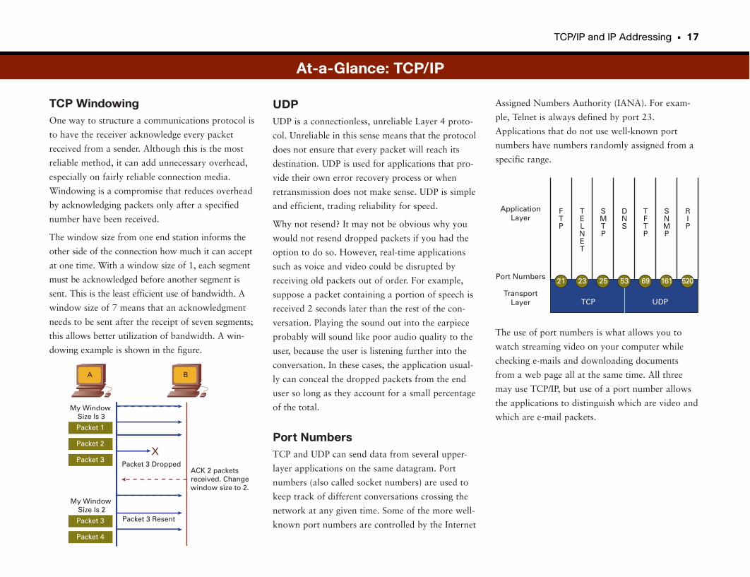
TCP/IP and IP Addressing • 17
TCP WindowingOne way to structure a communications protocol is
to have the receiver acknowledge every packet
received from a sender. Although this is the most
reliable method, it can add unnecessary overhead,
especially on fairly reliable connection media.
Windowing is a compromise that reduces overhead
by acknowledging packets only after a specified
number have been received.
The window size from one end station informs the
other side of the connection how much it can accept
at one time. With a window size of 1, each segment
must be acknowledged before another segment is
sent. This is the least efficient use of bandwidth. A
window size of 7 means that an acknowledgment
needs to be sent after the receipt of seven segments;
this allows better utilization of bandwidth. A win-
dowing example is shown in the figure.
Assigned Numbers Authority (IANA). For exam-
ple, Telnet is always defined by port 23.
Applications that do not use well-known port
numbers have numbers randomly assigned from a
specific range.
The use of port numbers is what allows you to
watch streaming video on your computer while
checking e-mails and downloading documents
from a web page all at the same time. All three
may use TCP/IP, but use of a port number allows
the applications to distinguish which are video and
which are e-mail packets.
UDPUDP is a connectionless, unreliable Layer 4 proto-
col. Unreliable in this sense means that the protocol
does not ensure that every packet will reach its
destination. UDP is used for applications that pro-
vide their own error recovery process or when
retransmission does not make sense. UDP is simple
and efficient, trading reliability for speed.
Why not resend? It may not be obvious why you
would not resend dropped packets if you had the
option to do so. However, real-time applications
such as voice and video could be disrupted by
receiving old packets out of order. For example,
suppose a packet containing a portion of speech is
received 2 seconds later than the rest of the con-
versation. Playing the sound out into the earpiece
probably will sound like poor audio quality to the
user, because the user is listening further into the
conversation. In these cases, the application usual-
ly can conceal the dropped packets from the end
user so long as they account for a small percentage
of the total.
Port NumbersTCP and UDP can send data from several upper-
layer applications on the same datagram. Port
numbers (also called socket numbers) are used to
keep track of different conversations crossing the
network at any given time. Some of the more well-
known port numbers are controlled by the Internet
Packet 3 DroppedACK 2 packetsreceived. Changewindow size to 2.
My WindowSize Is 3
Packet 3 Resent
My WindowSize Is 2
Packet 1
Packet 2
Packet 3
Packet 3
Packet 4
X
A B
At-a-Glance: TCP/IP
ApplicationLayer
Port Numbers
TransportLayer TCP UDP
21 23 25 53 69 161 520
FTP
TELNET
SMTP
DNS
TFTP
SNMP
RIP
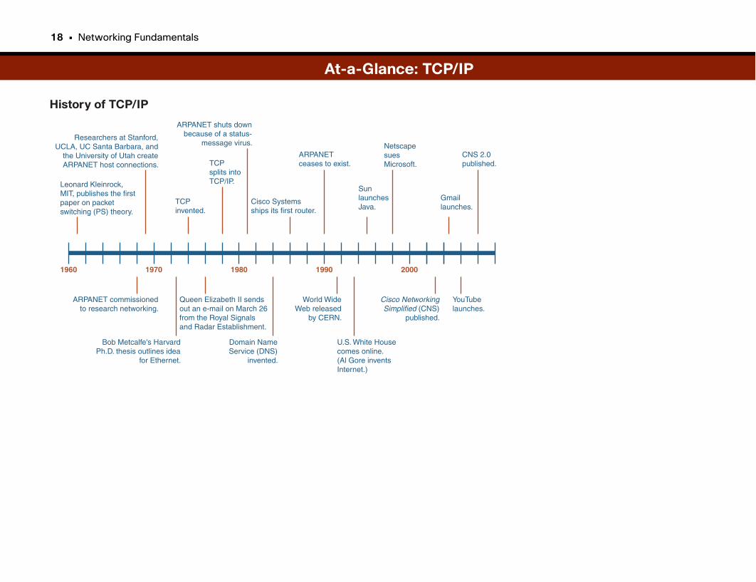
18 • Networking Fundamentals
History of TCP/IP
At-a-Glance: TCP/IP
Leonard Kleinrock,MIT, publishes the firstpaper on packetswitching (PS) theory.
Researchers at Stanford,UCLA, UC Santa Barbara, and
the University of Utah createARPANET host connections.
TCPinvented.
TCPsplits intoTCP/IP.
ARPANET shuts downbecause of a status-
message virus.
Cisco Systemsships its first router.
ARPANETceases to exist.
SunlaunchesJava.
NetscapesuesMicrosoft.
1960 1970 1980 1990 2000
U.S. White Housecomes online.(Al Gore inventsInternet.)
Cisco NetworkingSimplified (CNS)
published.
Domain NameService (DNS)
invented.
World WideWeb released
by CERN.
Queen Elizabeth II sendsout an e-mail on March 26from the Royal Signalsand Radar Establishment.
Bob Metcalfe's HarvardPh.D. thesis outlines idea
for Ethernet.
ARPANET commissionedto research networking.
YouTubelaunches.
CNS 2.0published.
Gmaillaunches.
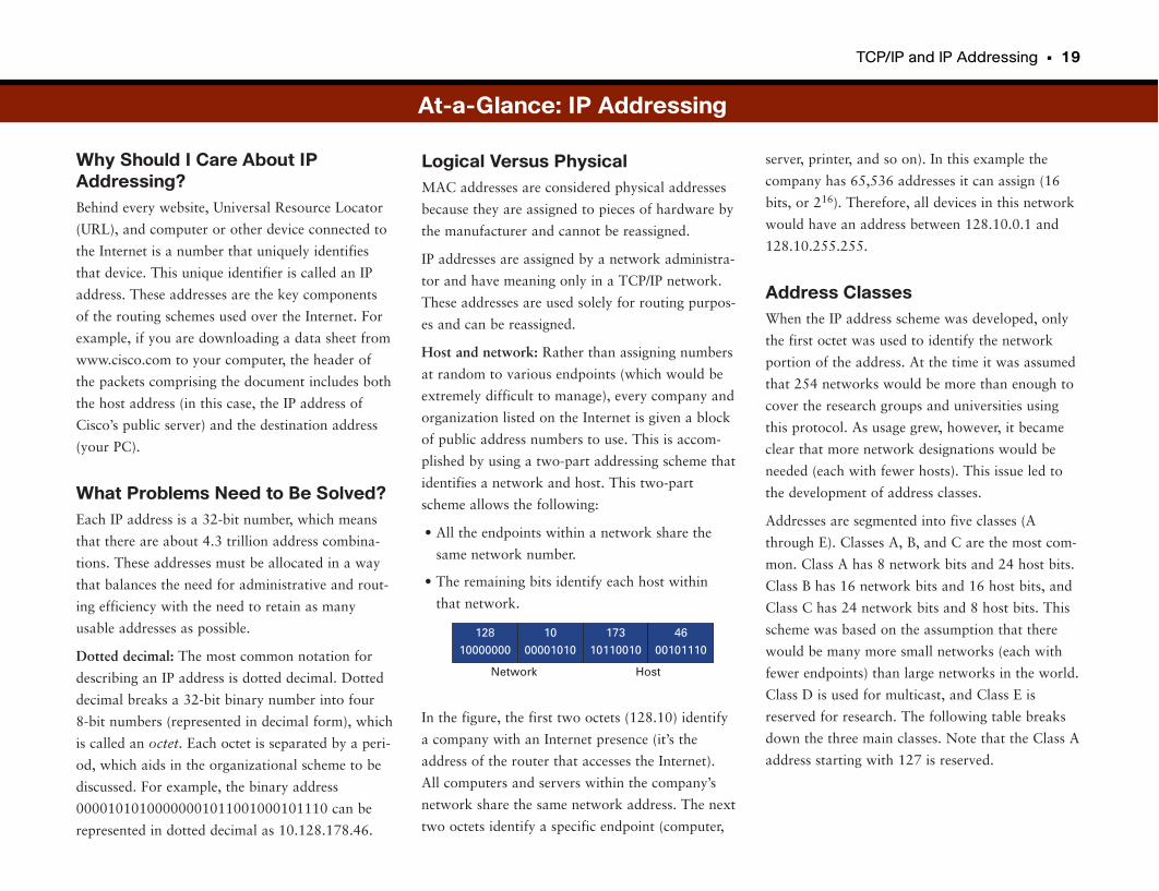
TCP/IP and IP Addressing • 19
Why Should I Care About IPAddressing?Behind every website, Universal Resource Locator
(URL), and computer or other device connected to
the Internet is a number that uniquely identifies
that device. This unique identifier is called an IP
address. These addresses are the key components
of the routing schemes used over the Internet. For
example, if you are downloading a data sheet from
www.cisco.com to your computer, the header of
the packets comprising the document includes both
the host address (in this case, the IP address of
Cisco’s public server) and the destination address
(your PC).
What Problems Need to Be Solved?Each IP address is a 32-bit number, which means
that there are about 4.3 trillion address combina-
tions. These addresses must be allocated in a way
that balances the need for administrative and rout-
ing efficiency with the need to retain as many
usable addresses as possible.
Dotted decimal: The most common notation for
describing an IP address is dotted decimal. Dotted
decimal breaks a 32-bit binary number into four
8-bit numbers (represented in decimal form), which
is called an octet. Each octet is separated by a peri-
od, which aids in the organizational scheme to be
discussed. For example, the binary address
00001010100000001011001000101110 can be
represented in dotted decimal as 10.128.178.46.
server, printer, and so on). In this example the
company has 65,536 addresses it can assign (16
bits, or 216). Therefore, all devices in this network
would have an address between 128.10.0.1 and
128.10.255.255.
Address ClassesWhen the IP address scheme was developed, only
the first octet was used to identify the network
portion of the address. At the time it was assumed
that 254 networks would be more than enough to
cover the research groups and universities using
this protocol. As usage grew, however, it became
clear that more network designations would be
needed (each with fewer hosts). This issue led to
the development of address classes.
Addresses are segmented into five classes (A
through E). Classes A, B, and C are the most com-
mon. Class A has 8 network bits and 24 host bits.
Class B has 16 network bits and 16 host bits, and
Class C has 24 network bits and 8 host bits. This
scheme was based on the assumption that there
would be many more small networks (each with
fewer endpoints) than large networks in the world.
Class D is used for multicast, and Class E is
reserved for research. The following table breaks
down the three main classes. Note that the Class A
address starting with 127 is reserved.
Logical Versus PhysicalMAC addresses are considered physical addresses
because they are assigned to pieces of hardware by
the manufacturer and cannot be reassigned.
IP addresses are assigned by a network administra-
tor and have meaning only in a TCP/IP network.
These addresses are used solely for routing purpos-
es and can be reassigned.
Host and network: Rather than assigning numbers
at random to various endpoints (which would be
extremely difficult to manage), every company and
organization listed on the Internet is given a block
of public address numbers to use. This is accom-
plished by using a two-part addressing scheme that
identifies a network and host. This two-part
scheme allows the following:
• All the endpoints within a network share the
same network number.
• The remaining bits identify each host within
that network.
In the figure, the first two octets (128.10) identify
a company with an Internet presence (it’s the
address of the router that accesses the Internet).
All computers and servers within the company’s
network share the same network address. The next
two octets identify a specific endpoint (computer,
Network
128
10000000
10
00001010
173
10110010
46
00101110
Host
At-a-Glance: IP Addressing
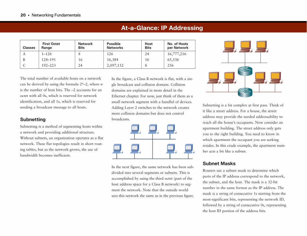
20 • Networking Fundamentals
The total number of available hosts on a network
can be derived by using the formula 2n–2, where n
is the number of host bits. The –2 accounts for an
octet with all 0s, which is reserved for network
identification, and all 1s, which is reserved for
sending a broadcast message to all hosts.
SubnettingSubnetting is a method of segmenting hosts within
a network and providing additional structure.
Without subnets, an organization operates as a flat
network. These flat topologies result in short rout-
ing tables, but as the network grows, the use of
bandwidth becomes inefficient.
Subnetting is a bit complex at first pass. Think of
it like a street address. For a house, the street
address may provide the needed addressability to
reach all the house’s occupants. Now consider an
apartment building. The street address only gets
you to the right building. You need to know in
which apartment the occupant you are seeking
resides. In this crude example, the apartment num-
ber acts a bit like a subnet.
Subnet MasksRouters use a subnet mask to determine which
parts of the IP address correspond to the network,
the subnet, and the host. The mask is a 32-bit
number in the same format as the IP address. The
mask is a string of consecutive 1s starting from the
most-significant bits, representing the network ID,
followed by a string of consecutive 0s, representing
the host ID portion of the address bits.
In the figure, a Class B network is flat, with a sin-
gle broadcast and collision domain. Collision
domains are explained in more detail in the
Ethernet chapter. For now, just think of them as a
small network segment with a handful of devices.
Adding Layer 2 switches to the network creates
more collision domains but does not control
broadcasts.
In the next figure, the same network has been sub-
divided into several segments or subnets. This is
accomplished by using the third octet (part of the
host address space for a Class B network) to seg-
ment the network. Note that the outside world
sees this network the same as in the previous figure.
At-a-Glance: IP Addressing
First Octet Network Possible Host No. of Hosts Classes Range Bits Networks Bits per Network
A 1–126 8 126 24 16,777,216
B 128–191 16 16,384 16 65,536
C 192–223 24 2,097,152 8 256
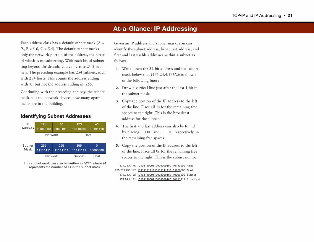
TCP/IP and IP Addressing • 21
Each address class has a default subnet mask (A =
/8, B = /16, C = /24). The default subnet masks
only the network portion of the address, the effect
of which is no subnetting. With each bit of subnet-
ting beyond the default, you can create 2n–2 sub-
nets. The preceding example has 254 subnets, each
with 254 hosts. This counts the address ending
with .0, but not the address ending in .255.
Continuing with the preceding analogy, the subnet
mask tells the network devices how many apart-
ments are in the building.
Identifying Subnet Addresses
Given an IP address and subnet mask, you can
identify the subnet address, broadcast address, and
first and last usable addresses within a subnet as
follows:
1. Write down the 32-bit address and the subnet
mask below that (174.24.4.176/26 is shown
in the following figure).
2. Draw a vertical line just after the last 1 bit in
the subnet mask.
3. Copy the portion of the IP address to the left
of the line. Place all 1s for the remaining free
spaces to the right. This is the broadcast
address for the subnet.
4. The first and last address can also be found
by placing ...0001 and ...1110, respectively, in
the remaining free spaces.
5. Copy the portion of the IP address to the left
of the line. Place all 0s for the remaining free
spaces to the right. This is the subnet number.
174.24.4.176 1010111000110000000100 10110000 Host
255.255.255.192 1111111111111111111111 11000000 Mask
174.24.4.128 1010111000110000000100 10000000 Subnet
174.24.4.191 1010111000110000000100 10111111 Broadcast
At-a-Glance: IP Addressing
Network
128
10000000
10
00001010
173
10110010
46
00101110
Host
IPAddress
SubnetMask
This subnet mask can also be written as "/24", where 24represents the number of 1s in the subnet mask.
Network
255
11111111
255
11111111
255
11111111
0
00000000
HostSubnet
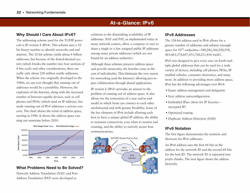
22 • Networking Fundamentals
Why Should I Care About IPv6?The addressing scheme used for the TCP/IP proto-
cols is IP version 4 (IPv4). This scheme uses a 32-
bit binary number to identify networks and end
stations. The 32-bit scheme yields about 4 billion
addresses, but because of the dotted-decimal sys-
tem (which breaks the number into four sections of
8 bits each) and other considerations, there are
really only about 250 million usable addresses.
When the scheme was originally developed in the
1980s, no one ever thought that running out of
addresses would be a possibility. However, the
explosion of the Internet, along with the increased
number of Internet-capable devices, such as cell
phones and PDAs (which need an IP address), has
made running out of IPv4 addresses a serious con-
cern. The chart shows the trend of address space,
starting in 1980. It shows the address space run-
ning out sometime before 2010.
What Problems Need to Be Solved?Network Address Translation (NAT) and Port
Address Translation (PAT) were developed as
solutions to the diminishing availability of IP
addresses. NAT and PAT, as implemented today in
many network routers, allow a company or user to
share a single or a few assigned public IP addresses
among many private addresses (which are not
bound by an address authority).
Although these schemes preserve address space
and provide anonymity, the benefits come at the
cost of individuality. This eliminates the very reason
for networking (and the Internet): allowing peer-to-
peer collaboration through shared applications.
IP version 6 (IPv6) provides an answer to the
problem of running out of address space. It also
allows for the restoration of a true end-to-end
model in which hosts can connect to each other
unobstructed and with greater flexibility. Some of
the key elements of IPv6 include allowing each
host to have a unique global IP address, the ability
to maintain connectivity even when in motion and
roaming, and the ability to natively secure host
communications.
At-a-Glance: IPv6
0.00%
100.00%
IPv4 Usage Trend
Time
To
tal
Sp
ace
Use
d
IPv4 Historical Usage
80.00%
60.00%
40.00%
20.00%
1980 1985 1990 200520001995 2010V
VNAT/PAT Breaks Peer-to-Peer
IPv4Internet
IPv6Internet
V
IPv6 AddressesThe 128-bit address used in IPv6 allows for a
greater number of addresses and subnets (enough
space for 1015 endpoints—340,282,366,920,938,
463,463,374,607,431,768,211,456 total!).
IPv6 was designed to give every user on Earth mul-
tiple global addresses that can be used for a wide
variety of devices, including cell phones, PDAs, IP-
enabled vehicles, consumer electronics, and many
more. In addition to providing more address space,
IPv6 has the following advantages over IPv4:
• Easier address management and delegation
• Easy address autoconfiguration
• Embedded IPsec (short for IP Security—
encrypted IP)
• Optimized routing
• Duplicate Address Detection (DAD)
IPv6 NotationThe first figure demonstrates the notation and
shortcuts for IPv6 addresses.
An IPv6 address uses the first 64 bits in the
address for the network ID and the second 64 bits
for the host ID. The network ID is separated into
prefix chunks. The next figure shows the address
hierarchy.
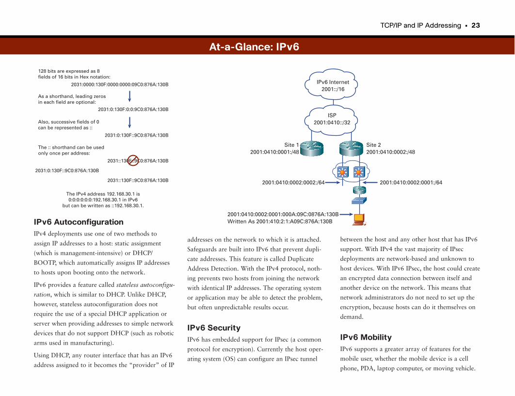
TCP/IP and IP Addressing • 23
IPv6 AutoconfigurationIPv4 deployments use one of two methods to
assign IP addresses to a host: static assignment
(which is management-intensive) or DHCP/
BOOTP, which automatically assigns IP addresses
to hosts upon booting onto the network.
IPv6 provides a feature called stateless autoconfigu-
ration, which is similar to DHCP. Unlike DHCP,
however, stateless autoconfiguration does not
require the use of a special DHCP application or
server when providing addresses to simple network
devices that do not support DHCP (such as robotic
arms used in manufacturing).
Using DHCP, any router interface that has an IPv6
address assigned to it becomes the “provider” of IP
between the host and any other host that has IPv6
support. With IPv4 the vast majority of IPsec
deployments are network-based and unknown to
host devices. With IPv6 IPsec, the host could create
an encrypted data connection between itself and
another device on the network. This means that
network administrators do not need to set up the
encryption, because hosts can do it themselves on
demand.
IPv6 MobilityIPv6 supports a greater array of features for the
mobile user, whether the mobile device is a cell
phone, PDA, laptop computer, or moving vehicle.
addresses on the network to which it is attached.
Safeguards are built into IPv6 that prevent dupli-
cate addresses. This feature is called Duplicate
Address Detection. With the IPv4 protocol, noth-
ing prevents two hosts from joining the network
with identical IP addresses. The operating system
or application may be able to detect the problem,
but often unpredictable results occur.
IPv6 SecurityIPv6 has embedded support for IPsec (a common
protocol for encryption). Currently the host oper-
ating system (OS) can configure an IPsec tunnel
ISP2001:0410::/32
Site 22001:0410:0002:/48
Site 12001:0410:0001:/48
2001:0410:0002:0001:/642001:0410:0002:0002:/64
2001:0410:0002:0001:000A:09C:0876A:130BWritten As 2001:410:2:1:A09C:876A:130B
IPv6 Internet2001::/16
At-a-Glance: IPv6
As a shorthand, leading zerosin each field are optional:
Also, successive fields of 0can be represented as ::
The :: shorthand can be used only once per address:
128 bits are expressed as 8fields of 16 bits in Hex notation:
2031:0000:130F:0000:0000:09C0:876A:130B
2031::130F::9C0:876A:130B
2031::130F::9C0:876A:130B
The IPv4 address 192.168.30.1 is0:0:0:0:0:0:192.168.30.1 in IPv6
but can be written as ::192.168.30.1.
2031:0:130F::9C0:876A:130B
2031:0:130F::9C0:876A:130B
2031:0:130F:0:0:9C0:876A:130B

24 • Networking Fundamentals
Mobile IPv6 (MIPv6) supports a more streamlined
approach to routing packets to and from the
mobile device. It also supports IPsec between the
mobile device and other network devices and hosts.
IPv6 TransitionThere have been many predictions over the years
about IPv6 migration, but the fact is that the IPv4
workarounds that have been developed in the
meantime have been pretty good. It could be that
despite being a superior solution to the address
scarcity issue, IPv6 may never displace IPv4 and its
work-arounds. To underscore this point, look back
at the chart at the beginning of this section. Here
we are in 2007, with only limited deployments of
IPv6, and with many more devices on the Internet
than anticipated back in the late 1990s, but IPv4
keeps chugging along.
Several factors may finally cause the transition—
first as IPv6 “islands” connected with IPv4 networks,
and then finally into end-to-end IPv6 networks.
These factors include the U.S. federal government
mandating that its networks must be IPv6-capable
by a certain date, Microsoft adopting IPv6 into
Windows starting with Vista, and Japan adopting
IPv6 as its country network addressing standard.
At a minimum, it is important for network admin-
istrators and companies to understand IPv6 and its
potential impacts so that they are prepared if and
when the transition occurs.
At-a-Glance: IPv6
1996-2005 2011+2006
Q1 Q2 Q3 Q4
2007
Q1 Q2 Q3 Q4
2008
Q1 Q2 Q3 Q4
2009
Q1 Q2 Q3 Q4
2010
Q1 Q2 Q3 Q4
Early Adopters
Application Port <= Duration 3+ Years =>
E-Europe, E-Japan, North America IPv6 Task Force,…
ISP Adoption <= Duration 3+ Years =>
Consumer Adoption <= Duration 5+ Years =>
Enterprise Adoption <= Duration 5+ Years =>
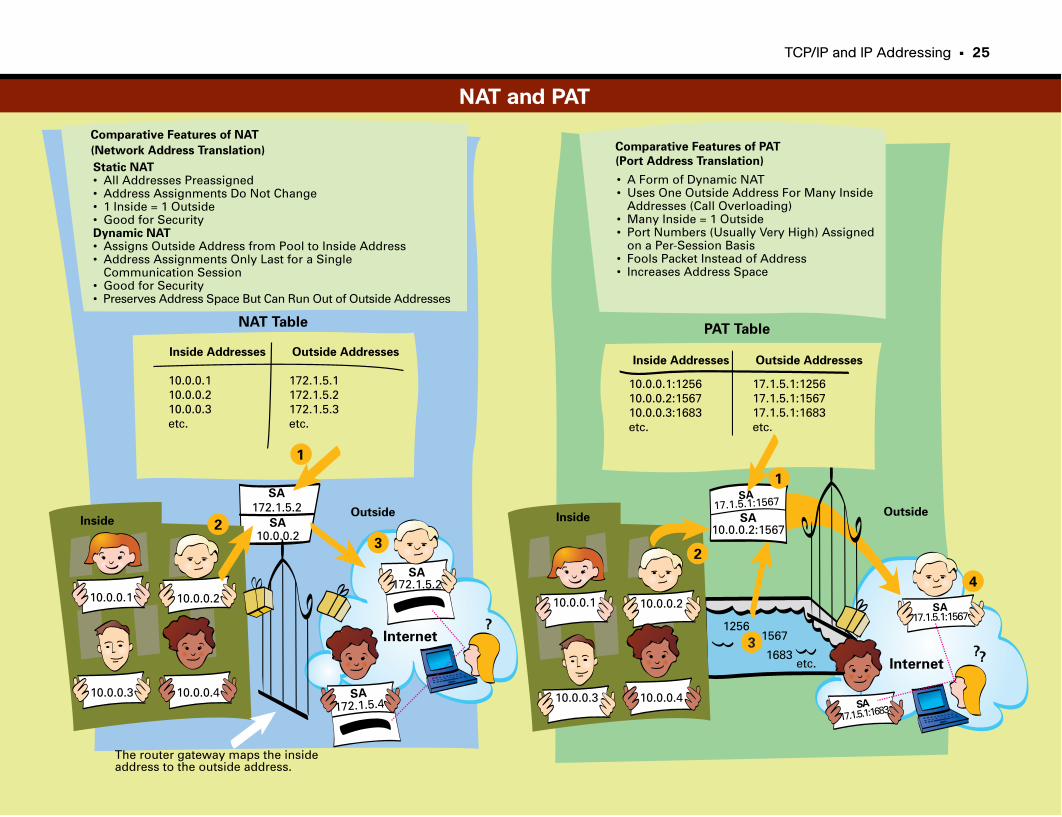
TCP/IP and IP Addressing • 25
Comparative Features of PAT
(Port Address Translation)
Inside Addresses Outside Addresses
10.0.0.1:125610.0.0.2:156710.0.0.3:1683etc.
17.1.5.1:125617.1.5.1:156717.1.5.1:1683etc.
Inside
SA17.1.5.1:1567
SA17.1.5.1:1567
SA
17.1.5.1:1683
SA10.0.0.2:1567
10.0.0.1 10.0.0.2
10.0.0.410.0.0.3
??Internet
• A Form of Dynamic NAT• Uses One Outside Address For Many Inside Addresses (Call Overloading)• Many Inside = 1 Outside• Port Numbers (Usually Very High) Assigned on a Per-Session Basis• Fools Packet Instead of Address• Increases Address Space
Outside
12561567
1683etc.
1
2
3
4
PAT TableNAT Table
Inside Addresses Outside Addresses
10.0.0.110.0.0.210.0.0.3etc.
172.1.5.1172.1.5.2172.1.5.3etc.
Inside
SA
172.1.5.2
SA172.1.5.2
SA
172.1.5.4
SA10.0.0.2
10.0.0.1 10.0.0.2
10.0.0.410.0.0.3
?Internet
Static NAT• All Addresses Preassigned• Address Assignments Do Not Change• 1 Inside = 1 Outside• Good for SecurityDynamic NAT• Assigns Outside Address from Pool to Inside Address• Address Assignments Only Last for a Single Communication Session• Good for Security• Preserves Address Space But Can Run Out of Outside Addresses
Outside
The router gateway maps the insideaddress to the outside address.
1
2
3
Comparative Features of NAT
(Network Address Translation)
NAT and PAT
Internet Applications
The Internet and Its ApplicationsWhat makes the Internet useful and interesting to the average person is not the
network, but rather the applications that operate on the network. The two
most common Internet applications in use today are e-mail and web browsers.
E-MailE-mail is one of the most common network applications in use today.
Although it might seem relatively new, e-mail was invented in the early 1970s.
Back then, of course, there was no Internet as we know it today, so having e-
mail was a bit like owning a car before there was a highway system.
Today, e-mail is so widespread that ISPs just assume that you want an e-mail
address and automatically assign you one (or even several) when you begin
your service agreement.
E-Mail Tools
There are two basic ways to create, send, and receive e-mails: with an e-mail
client and with a web-based e-mail tool:
• E-mail clients that are installed on individual machines are in wide use today.
The most popular are Microsoft Outlook/Outlook Express. E-mail clients
allow for the creation, distribution, retrieval, and storage of e-mails (as well as
some other useful features). These types of clients were originally designed so
that e-mails to and from an account could be accessed from a single machine.
E-mail clients physically move the e-mail from the e-mail server to your PC’s
hard drive. After the e-mail is downloaded, it no longer exists in the e-mail
provider’s network. The e-mail exists in your e-mail client program (on the
PC’s hard drive) until you delete it.
• Web-based e-mail tools, such as Google Mail, allow users to access their
e-mail from any machine connected to the Internet. Users log in to the web-
site with their registered name and password. Then they are given access to
a web-based e-mail client that has all the basic abilities of e-mail clients,
such as the ability to create, send, and receive e-mails. Many have more
advanced features, such as the ability to send and receive file attachments
and create and use address books.
Web-based e-mail tools differ from e-mail clients in that the e-mail is not
downloaded to your PC’s hard drive. It exists only on the e-mail provider’s
network until you delete it. Some people use a combination of web-based e-
mail and e-mail clients. For example, you may use the web-based e-mail tool
to access your e-mail when you are away from home and not using your
home PC. When you are at home, you could then use your e-mail client.
What’s Up with the @ Sign?
All e-mail addresses are made up of two parts: a recipient part and a domain
name. An @ symbol separates the two parts to denote that a recipient is
unique within a domain name. The domain name is usually the name of your
ISP (or your company if you have e-mail there), and, like a website, an e-mail
domain has an associated IP address. This allows (actually, requires) the use of
a DNS server to translate the domain name portion of an e-mail address to the
IP address of the server where the e-mail account resides.
The recipient part is the chosen identifier that you are known by within the e-
mail domain. There are a lot of possibilities for choosing the recipient. Here
are a few popular styles:
Firstname.Lastname John.Brown
FirstinitialLastname JBrown
Nickname DowntownJohnnyBrown
Personalized license plate L8RG8R
Other obscure reference GrassyKnoll63
When picking an e-mail address, remember that sometimes you’ll have to ver-
bally tell someone your e-mail address, so “X3UT67B” is inadvisable.
28 • Networking Fundamentals
Sending E-Mails
E-mails are distributed using a (OSI Layer 7) protocol called Simple Mail
Transfer Protocol (SMTP). SMTP normally operates on powerful computers
dedicated to e-mail distribution, called SMTP servers. When you create and
send an e-mail, your e-mail client sends the file to the SMTP server. The server
pulls out the addresses from the message. (You can send e-mails to multiple
recipients.) For each domain name, the SMTP server must send a message to a
DNS to get the IP address of each recipient’s e-mail server. If the recipient is on
the same server as you (that is, if you send an e-mail to someone with the
same domain name), this step is unnecessary.
After your SMTP server knows the IP address of the recipient’s server, your
SMTP server transfers the e-mail message to the recipient’s SMTP server. If
there are multiple recipients in different e-mail domains, a separate copy of the
e-mail is transferred to each recipient’s SMTP server. According to the name of
the protocol, this is all pretty simple.
Receiving E-Mails
E-mail is often received via a different server than the one that sends e-mail.
The type of server depends on which type of e-mail tool you use. For those
using an e-mail client, your e-mail is probably delivered to you via the most
common method, Post Office Protocol 3 (POP3) server. (We have no idea what
happened to the first two.) The POP3 server receives all its e-mails from SMTP
servers and sorts them into file spaces dedicated to each user (much the same
way mail is put into post office boxes at a local post office—thus the name).
When you open your e-mail client, it contacts the POP3 server to request all
the new e-mails. The e-mails are then transferred to your PC, and in most
cases the e-mails are erased from the POP3 server.
Another common method (or protocol) for mail retrieval is an Internet Mail
Access Protocol (IMAP) server. This is the protocol normally used by web-
based e-mail clients, and corporate e-mail systems such as Microsoft
Exchange. The IMAP server receives and sorts e-mail in much the same way as
a POP3 server. Unlike POP3, however, IMAP does not transfer the e-mails to
the machine of the account holder; instead, it keeps e-mail on the server. This
allows users to connect to use their e-mail account from multiple machines.
IMAP also allows for server-side filtering, a method of presorting e-mail based
on rules before it even gets to your PC. It’s kind of like having a friendly
postal worker who sorts all your bills to the top and magazines to the bottom.
Two main issues with IMAP servers are storage space and working offline.
Most Internet e-mail services put a limit on the amount of storage each sub-
scriber gets (some charge extra for additional storage space). In addition, these
services often limit the file size of attachments (such as photos). The other
issue is the ability to work offline or when not connected to the Internet. One
solution is called caching, which temporarily places the subscriber’s e-mail
information on whatever PC he or she wants to work offline with. When the
user reconnects, any e-mails created while offline are sent, and any new incom-
ing e-mails can be viewed.
Web BrowsingBrowsing web pages on the Internet is another common network application.
Browsers run on a computer and allow a viewer to see website content.
Website content resides on a server, a powerful computer with a lot of disk
space and lots of computing cycles. The protocol that allows browsers and
servers to communicate is HTTP.
What Are HTTP and HTML, and What Do They Do?
You might have noticed that many Internet sites include the letters HTTP in
the site address that appears in the address line of your web browser. HTTP
(another OSI Layer 7 protocol) defines the rules for transferring information,
files, and multimedia on web pages. Hypertext Markup Language (HTML) is
the language used within HTTP. HTML is actually a fairly simple, easy-to-
learn computer language that embeds symbols into a text file to specify visual
or functional characteristics such as font size, page boundaries, and applica-
tion usages (such as launching an e-mail tool when a user clicks certain links).
When the developer of an HTTP file (or web page) wants to allow for a jump
to a different place on the page, or even a jump to a new page, he or she sim-
ply places the appropriate symbols into the file. People viewing the page just
see the link, which is most commonly specified with blue, underlined text. The
ease of jumping from site to site (called web surfing) is one of the reasons for
the proliferation of websites on, and growth of, the Internet.
Several free and commercial tools allow you to create a web page using
HTML without having to know all the rules.
One of the issues with HTML is that it is fairly limited as far as what it can do
given that it works only on text and still pictures. To achieve some of the real-
ly cool moving graphics and web page features, other tools such as Flash,
XML, JavaScript, or other scripting languages are needed.
Internet Applications • 29
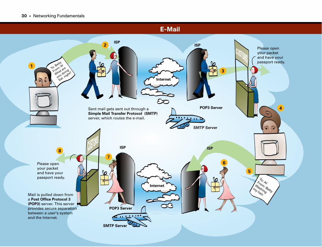
To: Betty
From: Al
What are
you doing
Sat. night?
1
2
3
4
5
6
7
8
To: AlFrom: Betty
Washingmy hair.
POP3 Server
POP3 Server
SMTP Server
SMTP Server
Please openyour packet and have yourpassport ready.
Please openyour packet and have yourpassport ready.
ISPISP
ISP ISP
Internet
Internet
Sent mail gets sent out through a Simple Mail Transfer Protocol (SMTP)
server, which routes the e-mail.
Mail is pulled down froma Post Office Protocol 3
(POP3) server. This serverprovides secure separationbetween a user's systemand the Internet.
30 • Networking Fundamentals
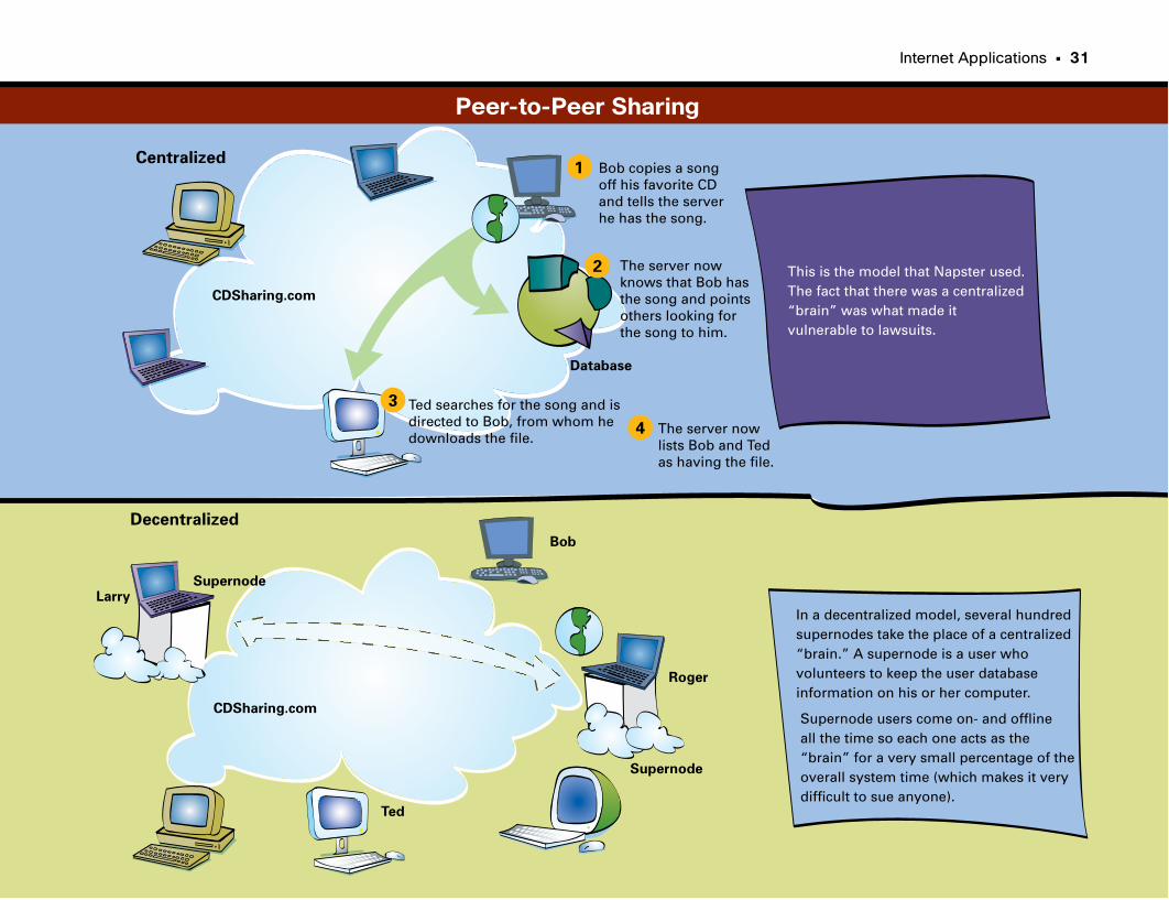
Internet Applications • 31
Centralized
Decentralized
1
2
3
4
Bob copies a songoff his favorite CDand tells the serverhe has the song.
The server nowknows that Bob hasthe song and pointsothers looking forthe song to him.
Ted searches for the song and isdirected to Bob, from whom he downloads the file.
The server nowlists Bob and Ted as having the file.
Database
This is the model that Napster used. The fact that there was a centralized“brain” was what made itvulnerable to lawsuits.
CDSharing.com
CDSharing.com
Larry
Bob
Roger
Ted
Supernode
Supernode
In a decentralized model, several hundredsupernodes take the place of a centralized“brain.” A supernode is a user who volunteers to keep the user database information on his or her computer.
Supernode users come on- and offlineall the time so each one acts as the “brain” for a very small percentage of the overall system time (which makes it very difficult to sue anyone).
Peer-to-Peer Sharing
Part II
Networking InfrastructureWith the fundamentals of networking under our belt, we can now take a closer look at the infrastructure
that makes up the networks we all use. This section focuses on the switches and routers that make up net-
works, along with the protocols that drive them.
We start this section with a discussion of the Ethernet protocol, which defines the rules and processes by
which computers in a local area communicate. Long before the Internet was in use, computers communi-
cated locally using the Ethernet protocol, and it is still widely used.
We then move on to local-area network (LAN) switching, an extension of the Ethernet protocol required
when there are more computers in a local segment than can communicate efficiently. Switching is one of
the core technologies in networking.
One of the necessities in networking is link redundancy, something that makes it more likely that data
reaches its intended target. Sometimes, however, link redundancy can create loops in the network, which
causes an explosion of administrative traffic that can take down a network in a matter of minutes.
Spanning Tree is one of the mechanisms that keeps these “broadcast storms” from wiping out your local
network, so we look at how this important protocol works.
We end this section with routing, which provides the basis for network communication over long dis-
tances. The advent of routing allowed the growth of the Internet and corporate networking as we know it
today. This section explores how routing works and how routers communicate.
Ethernet 35
LAN Switching 43
Spanning Tree 49
Routing 55

Ethernet
In contrast, Token Ring had more sophisticated tools (than crawling on your
knees) for finding the breaks. It was usually pretty obvious where the token
stopped being passed and, voilà, you had your culprit.
The battle for the LAN continued for more than ten years, until eventually
Ethernet became the predominant technology. Arguably, it was the widespread
adoption of Ethernet switching that drove the final nail in Token Ring’s coffin.
Other LAN technologies, such as AppleTalk and Novell IPX, have been and
continue to be introduced, but Ethernet prevails as the predominant technolo-
gy for local high-speed connectivity.
Thankfully, we have left behind early media such as coax for more sophisticated
technologies.
What Is Ethernet?Ethernet describes a system that links the computers in a building or within a
local area. It consists of hardware (a network interface card), software, and
cabling used to connect the computers. All computers on an Ethernet are
attached to a shared data link, as opposed to traditional point-to-point net-
works, in which a single device connects to another single device.
Because all computers share the same data link on an Ethernet network, the
network needs a protocol to handle contention if multiple computers want to
transmit data at the same time, because only one can talk at a time without
causing interference. Metcalfe’s invention introduced the carrier sense multiple
access collision detect (CSMA/CD) protocol. CSMA/CD defines how a com-
puter should listen to the network before transmitting. If the network is quiet,
the computer can transmit its data. However, a problem arises if more than
one computer listens, hears silence, and transmits at the same time: The data
collides. The collision-detect part of CSMA/CD defines a method in which
transmitting computers back off when collisions occur and randomly attempt
to restart transmission. Ethernet originally operated at 3 Mbps, but today it
History of EthernetRobert Metcalfe developed Ethernet at the famous Xerox Palo Alto Research
Center (PARC) in 1972. The folks at Xerox PARC had developed a personal
workstation with a graphical user interface. They needed a technology to net-
work these workstations with their newly developed laser printers. (Remember,
the first PC, the MITS altair, was not introduced to the public until 1975.)
Metcalfe originally called this network the Alto Aloha Network. He changed
the name to Ethernet in 1973 to make it clear that any type of device could
connect to his network. He chose the name “ether” because the network car-
ried bits to every workstation in the same manner that scientists once thought
waves were propagated through space by the “luminiferous ether.”
Metcalfe’s first external publication concerning Ethernet was available to the
public in 1976. Metcalfe left Xerox, and in 1979 he got Digital Equipment
Corporation (DEC), Intel, and Xerox to agree on a common Ethernet standard
called DIX. In 1982, the Institute of Electrical and Electronic Engineers (IEEE)
adopted a standard based on Metcalfe’s Ethernet.
Ethernet took off in academic networks and some corporate networks. It was
cheap, and public domain protocols such as Internet Protocol (IP) ran natively
on it. However, another company (IBM) wanted the world to adopt its proto-
col instead, called Token Ring. Before switching was introduced, Ethernet was
more difficult to troubleshoot than Token Ring. Although Ethernet was less
expensive to implement, larger corporations chose Token Ring because of their
relationship with IBM and the ability to more easily troubleshoot problems.
Early Ethernet used media such as coaxial cable, and a network could literally
be a single long, continuous segment of coax cable tied into many computers.
(This cable was known as Thinnet or Thicknet, depending on the thickness of
the coax used.) When someone accidentally kicked the cable under his or her
desk, this often produced a slight break in the network. A break meant that
no one on the network could communicate, not just the poor schmuck who
kicked the cable. Debugging usually entailed crawling under desks and
following the cable until the break was found.
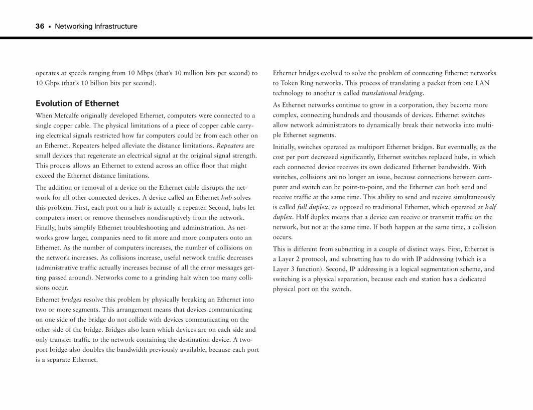
36 • Networking Infrastructure
operates at speeds ranging from 10 Mbps (that’s 10 million bits per second) to
10 Gbps (that’s 10 billion bits per second).
Evolution of EthernetWhen Metcalfe originally developed Ethernet, computers were connected to a
single copper cable. The physical limitations of a piece of copper cable carry-
ing electrical signals restricted how far computers could be from each other on
an Ethernet. Repeaters helped alleviate the distance limitations. Repeaters are
small devices that regenerate an electrical signal at the original signal strength.
This process allows an Ethernet to extend across an office floor that might
exceed the Ethernet distance limitations.
The addition or removal of a device on the Ethernet cable disrupts the net-
work for all other connected devices. A device called an Ethernet hub solves
this problem. First, each port on a hub is actually a repeater. Second, hubs let
computers insert or remove themselves nondisruptively from the network.
Finally, hubs simplify Ethernet troubleshooting and administration. As net-
works grow larger, companies need to fit more and more computers onto an
Ethernet. As the number of computers increases, the number of collisions on
the network increases. As collisions increase, useful network traffic decreases
(administrative traffic actually increases because of all the error messages get-
ting passed around). Networks come to a grinding halt when too many colli-
sions occur.
Ethernet bridges resolve this problem by physically breaking an Ethernet into
two or more segments. This arrangement means that devices communicating
on one side of the bridge do not collide with devices communicating on the
other side of the bridge. Bridges also learn which devices are on each side and
only transfer traffic to the network containing the destination device. A two-
port bridge also doubles the bandwidth previously available, because each port
is a separate Ethernet.
Ethernet bridges evolved to solve the problem of connecting Ethernet networks
to Token Ring networks. This process of translating a packet from one LAN
technology to another is called translational bridging.
As Ethernet networks continue to grow in a corporation, they become more
complex, connecting hundreds and thousands of devices. Ethernet switches
allow network administrators to dynamically break their networks into multi-
ple Ethernet segments.
Initially, switches operated as multiport Ethernet bridges. But eventually, as the
cost per port decreased significantly, Ethernet switches replaced hubs, in which
each connected device receives its own dedicated Ethernet bandwidth. With
switches, collisions are no longer an issue, because connections between com-
puter and switch can be point-to-point, and the Ethernet can both send and
receive traffic at the same time. This ability to send and receive simultaneously
is called full duplex, as opposed to traditional Ethernet, which operated at half
duplex. Half duplex means that a device can receive or transmit traffic on the
network, but not at the same time. If both happen at the same time, a collision
occurs.
This is different from subnetting in a couple of distinct ways. First, Ethernet is
a Layer 2 protocol, and subnetting has to do with IP addressing (which is a
Layer 3 function). Second, IP addressing is a logical segmentation scheme, and
switching is a physical separation, because each end station has a dedicated
physical port on the switch.
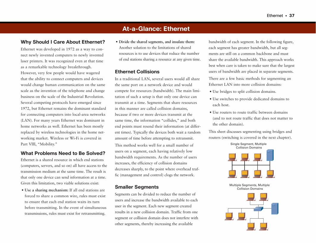
Ethernet • 37
Why Should I Care About Ethernet?Ethernet was developed in 1972 as a way to con-
nect newly invented computers to newly invented
laser printers. It was recognized even at that time
as a remarkable technology breakthrough.
However, very few people would have wagered
that the ability to connect computers and devices
would change human communication on the same
scale as the invention of the telephone and change
business on the scale of the Industrial Revolution.
Several competing protocols have emerged since
1972, but Ethernet remains the dominant standard
for connecting computers into local-area networks
(LAN). For many years Ethernet was dominant in
home networks as well. Ethernet has been mostly
replaced by wireless technologies in the home net-
working market. Wireless or Wi-Fi is covered in
Part VIII, “Mobility.”
What Problems Need to Be Solved?Ethernet is a shared resource in which end stations
(computers, servers, and so on) all have access to the
transmission medium at the same time. The result is
that only one device can send information at a time.
Given this limitation, two viable solutions exist:
• Use a sharing mechanism: If all end stations are
forced to share a common wire, rules must exist
to ensure that each end station waits its turn
before transmitting. In the event of simultaneous
transmissions, rules must exist for retransmitting.
bandwidth of each segment. In the following figure,
each segment has greater bandwidth, but all seg-
ments are still on a common backbone and must
share the available bandwidth. This approach works
best when care is taken to make sure that the largest
users of bandwidth are placed in separate segments.
There are a few basic methods for segmenting an
Ethernet LAN into more collision domains:
• Use bridges to split collision domains.
• Use switches to provide dedicated domains to
each host.
• Use routers to route traffic between domains
(and to not route traffic that does not matter to
the other domain).
This sheet discusses segmenting using bridges and
routers (switching is covered in the next chapter).
• Divide the shared segments, and insulate them:
Another solution to the limitations of shared
resources is to use devices that reduce the number
of end stations sharing a resource at any given time.
Ethernet CollisionsIn a traditional LAN, several users would all share
the same port on a network device and would
compete for resources (bandwidth). The main limi-
tation of such a setup is that only one device can
transmit at a time. Segments that share resources
in this manner are called collision domains,
because if two or more devices transmit at the
same time, the information “collides,” and both
end points must resend their information (at differ-
ent times). Typically the devices both wait a random
amount of time before attempting to retransmit.
This method works well for a small number of
users on a segment, each having relatively low
bandwidth requirements. As the number of users
increases, the efficiency of collision domains
decreases sharply, to the point where overhead traf-
fic (management and control) clogs the network.
Smaller SegmentsSegments can be divided to reduce the number of
users and increase the bandwidth available to each
user in the segment. Each new segment created
results in a new collision domain. Traffic from one
segment or collision domain does not interfere with
other segments, thereby increasing the available
At-a-Glance: Ethernet
Single Segment, Multiple Collision Domains
Multiple Segments, Multiple Collision Domains
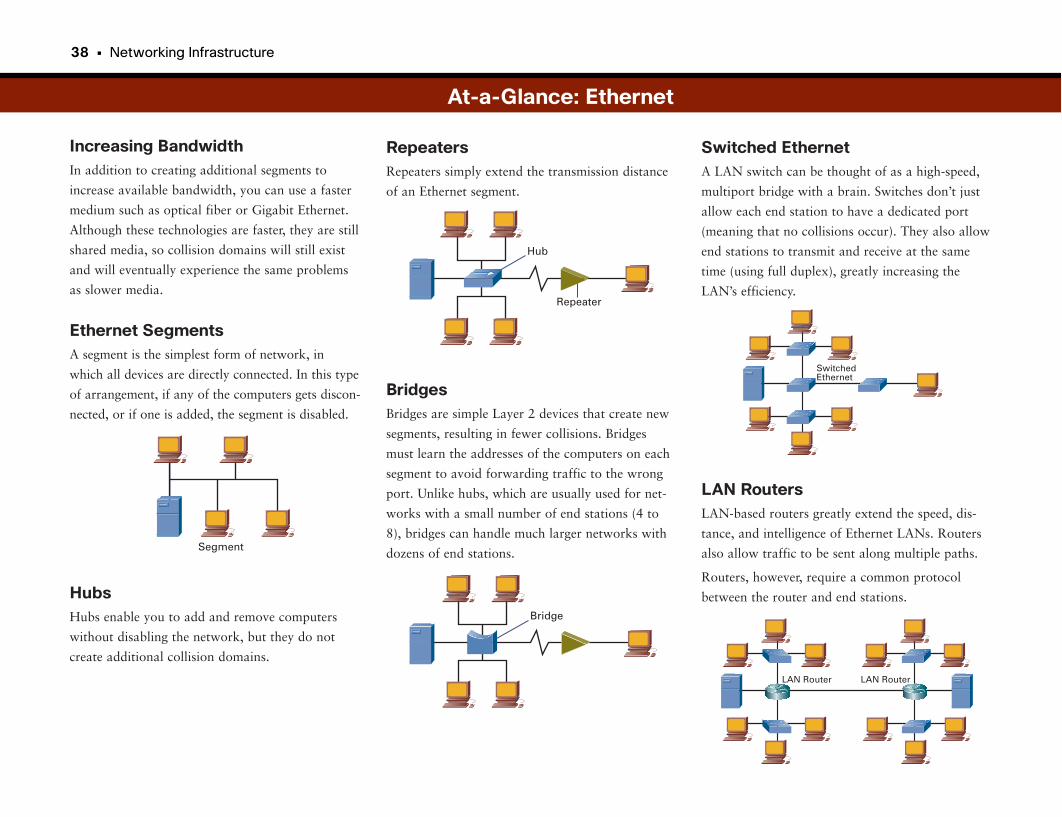
38 • Networking Infrastructure
Increasing BandwidthIn addition to creating additional segments to
increase available bandwidth, you can use a faster
medium such as optical fiber or Gigabit Ethernet.
Although these technologies are faster, they are still
shared media, so collision domains will still exist
and will eventually experience the same problems
as slower media.
Ethernet SegmentsA segment is the simplest form of network, in
which all devices are directly connected. In this type
of arrangement, if any of the computers gets discon-
nected, or if one is added, the segment is disabled.
HubsHubs enable you to add and remove computers
without disabling the network, but they do not
create additional collision domains.
RepeatersRepeaters simply extend the transmission distance
of an Ethernet segment.
BridgesBridges are simple Layer 2 devices that create new
segments, resulting in fewer collisions. Bridges
must learn the addresses of the computers on each
segment to avoid forwarding traffic to the wrong
port. Unlike hubs, which are usually used for net-
works with a small number of end stations (4 to
8), bridges can handle much larger networks with
dozens of end stations.
At-a-Glance: Ethernet
Switched EthernetA LAN switch can be thought of as a high-speed,
multiport bridge with a brain. Switches don’t just
allow each end station to have a dedicated port
(meaning that no collisions occur). They also allow
end stations to transmit and receive at the same
time (using full duplex), greatly increasing the
LAN’s efficiency.
LAN RoutersLAN-based routers greatly extend the speed, dis-
tance, and intelligence of Ethernet LANs. Routers
also allow traffic to be sent along multiple paths.
Routers, however, require a common protocol
between the router and end stations.
Segment
Hub
Repeater
Bridge
SwitchedEthernet
LAN RouterLAN Router
Ethernet • 39
What They Gave AwayIn the 1970s Xerox Corporation assembled a
group of talented researchers to investigate new
technologies. The new group was located in the
newly opened Palo Alto Research Center (PARC),
well away from the corporate headquarters in
Connecticut.
In addition to developing Ethernet, the brilliant
folks at the PARC invented the technology for
what eventually became the personal computer
(PC), the graphical user interface (GUI), laser print-
ing, and very-large-scale integration (VLSI).
Inexplicably, Xerox Corporation failed to recognize
the brilliance (and commercial viability) of many of
these homegrown innovations and let them walk
out the door.
To give you an idea of what this cost Xerox in
terms of opportunity, the worldwide budget for
Ethernet equipment was more than $7 billion in
2006 and was expected to grow to more than $10
billion by 2009. Just imagine if a single company
owned the assets of Apple, Intel, Cisco, HP, and
Microsoft. There almost was such a company. Its
name is Xerox.
At-a-Glance: Ethernet
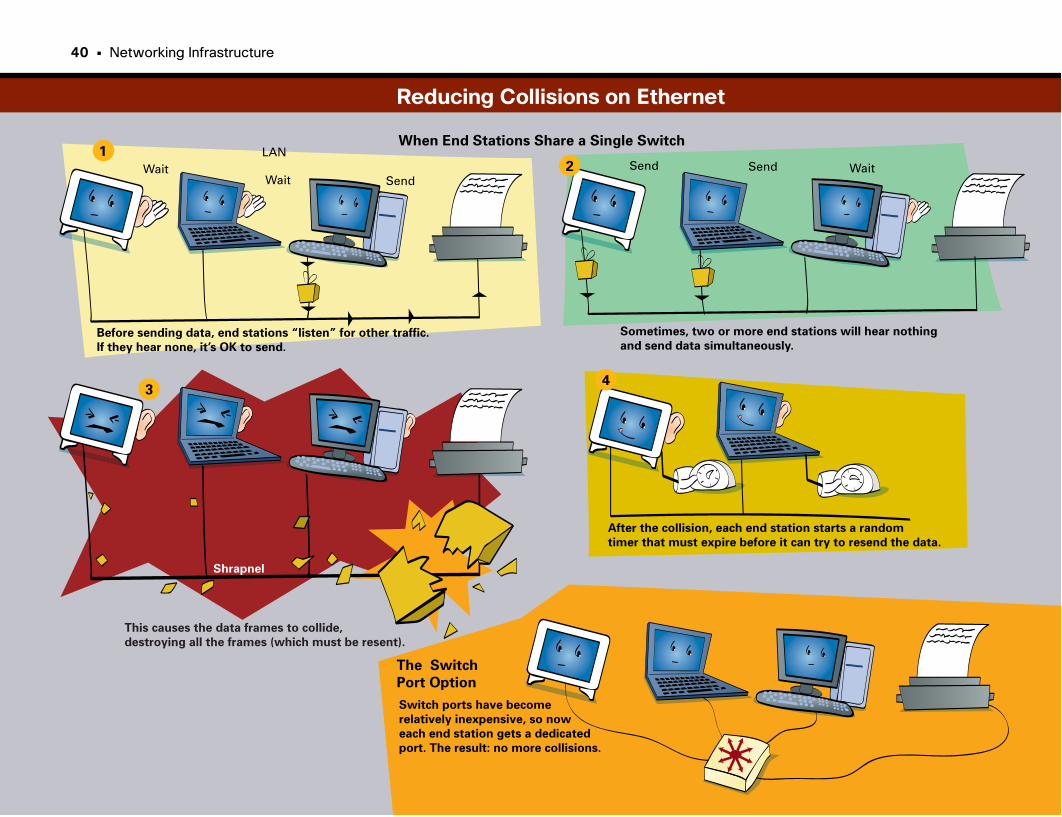
12
34
LANWait
WaitWait
SendSend Send
Before sending data, end stations “listen” for other traffic.
If they hear none, it’s OK to send.
When End Stations Share a Single Switch
Sometimes, two or more end stations will hear nothing
and send data simultaneously.
Shrapnel
This causes the data frames to collide,
destroying all the frames (which must be resent).
After the collision, each end station starts a random
timer that must expire before it can try to resend the data.
The Switch
Port Option
Switch ports have become
relatively inexpensive, so now
each end station gets a dedicated
port. The result: no more collisions.
Reducing Collisions on Ethernet
40 • Networking Infrastructure

This page intentionally left blank
LAN Switching
Fast Computers Need Faster NetworksThe PC emerged as the most common desktop computer in the 1980s. LANs
emerged as a way to network PCs in a common location. Networking tech-
nologies such as Token Ring and Ethernet allowed users to share resources
such as printers and exchange files with each other. As originally defined,
Ethernet and Token Ring provided network access to multiple devices on the
same network segment or ring. These LAN technologies have inherent limita-
tions as to how many devices can connect to a single segment, as well as the
physical distance between computers. Desktop computers got faster, the number
of computers grew, operating systems began multitasking (allowing multiple
tasks to operate at the same time), and applications became more network-
centric. All these advancements resulted in congestion on LANs.
To address these issues, two device types emerged: repeaters and bridges.
Repeaters are simple Open Systems Interconnection (OSI) Layer 1 devices that
allow networks to extend beyond their defined physical distances (which were
limited to about 150 feet without the use of a repeater).
Bridges are OSI Layer 2 devices that physically split a segment into two and
reduce the amount of traffic on either side of the bridge. This setup allows
more devices to connect to the LAN and reduces congestion. LAN switches
emerged as a natural extension of bridging, revolutionizing the concept of
local-area networking.
Switching Basics: It’s a BridgeNetwork devices have one primary purpose: to pass network traffic from one
segment to another. (There are exceptions, of course, such as network analyz-
ers, which inspect traffic as it goes by.) With devices that independently make
forwarding decisions, traffic can travel from its source to the destination. The
higher up the OSI model a device operates, the deeper it looks into a packet to
make a forwarding decision. Railroad-switching stations provide a similar
example. The switches enable a train to enter the appropriate tracks (path)
that take it to its final destination. If the switches are set wrong, a train can
end up traveling to the wrong destination or traveling in a circle.
Switching technology emerged as the replacement for bridging. Switches pro-
vide all the features of traditional bridging and more. Compared to bridges,
switches provide superior throughput performance, higher port density, and
lower per-port cost.
The different types of bridging include the following:
• Transparent bridging primarily occurs in Ethernet networks.
• Source-route bridging occurs in Token Ring networks.
• Translational bridging occurs between different media. For example, a trans-
lational bridge might connect a Token Ring network to an Ethernet network.
Bridging and switching occur at the data link layer (Layer 2 in the OSI model),
which means that bridges control data flow, provide transmission error han-
dling, and enable access to physical media. Basic bridging is not complicated:
A bridge or switch analyzes an incoming frame, determines where to forward
the frame based on the packet’s header information (which contains informa-
tion on the source and destination addresses), and forwards the frame toward
its destination. With transparent bridging, forwarding decisions happen one
hop (or network segment) at a time. With source-route bridging, the frame
contains a predetermined path to the destination.
Bridges and switches divide networks into smaller, self-contained units.
Because only a portion of the traffic is forwarded, bridging reduces the overall
traffic that devices see on each connected network. The bridge acts as a kind
of firewall in that it prevents frame-level errors from propagating from one
segment to another. Bridges also accommodate communication among more
devices than are supported on a single segment or ring.
Bridges and switches essentially extend the effective length of a LAN, permit-
ting more workstations to communicate with each other within a single broad-
cast domain. The primary difference between switches and bridges is that
bridges segment a LAN into a few smaller segments. Switches, through their
increased port density and speed, permit segmentation on a much larger scale.
Modern-day switches used in corporate networks have hundreds of ports per
chassis (unlike the four-port box connected to your cable modem).
44 • Networking Infrastructure
Additionally, modern-day switches interconnect LAN segments operating at
different speeds.
Switching describes technologies that are an extension of traditional bridges.
Switches connect two or more LAN segments and make forwarding decisions
about whether to transmit packets from one segment to another. When a
frame arrives, the switch inspects the destination and source Media Access
Control (MAC) addresses in the packet. (This is an example of store-and-
forward switching.) The switch places an entry in a table indicating that the
source MAC address is located off the switch interface on which the packet
arrived. The bridge then consults the same table for an entry for the destina-
tion MAC address. If it has an entry for the destination MAC address, and the
entry indicates that the MAC address is located on a different port from which
the packet was received, the switch forwards the frame to the specified port.
If the switch table indicates that the destination MAC address is located on the
same interface on which the frame was just received, the bridge does not for-
ward the frame. Why send it back onto the network segment from which it
came? This decision is where a switch reduces network congestion. Finally, if
the destination MAC address is not in the switch’s table, this indicates that the
switch has not yet seen a frame destined for this MAC address. In this case,
the switch then forwards the frames out all other ports (called flooding) except
the one on which the packet was received.
At their core, switches are multiport bridges. However, switches have radically
matured into intelligent devices, replacing both bridges and hubs. Switches not
only reduce traffic through the use of bridge tables, but also offer new func-
tionality that supports high-speed connections, virtual LANs, and even tradi-
tional routing.
Switching EthernetsAs switch Ethernet ports became less expensive, switches replaced hubs in the
wiring closet. Initially, when switches were introduced, network administrators
plugged hubs (containing multiple hosts) into switch ports. But eventually, it
became cost-effective to plug the hosts directly into a switch port. This
arrangement gives each host its own dedicated Ethernet and removes the possi-
bility of collisions. Because a dedicated switch connection has only two devices
(the switch and the host), you can configure an Ethernet switch port as full
duplex. This means that a device can receive incoming traffic and transmit
traffic simultaneously. End stations have considerably more bandwidth when
they use switches. Ethernet can run at multiple speeds: 10 Mbps, 100 Mbps,
1 Gbps, and 10 Gbps. Therefore, switches can provide connectivity at these
speeds. However, network applications and the web create considerably more
network traffic, reintroducing new congestion problems. Switches can use
quality of service (QoS) and other mechanisms to help solve the congestion
issue.
Switches Take Over the WorldAs switches established themselves in networks, vendors added increasing
functionality. Modern switches can perform forwarding decisions based on
Layer 3 routing, as well as on Layer 4 and above. Even though switches can
perform the functions of other higher-layer devices such as routers and content
switches, you still must separate these functionalities to avoid single points of
failure. Switches are the workhorse of networks, providing functionality across
almost all layers of the OSI model reliably and quickly. Switches can also pro-
vide power to devices such as IP-based phones using the same Ethernet con-
nection. Again, this applies to very large switches serving corporate networks
rather than the switches in a small office or home.
LAN Switching • 45
Why Should I Care About Switching?Advances in switching technology combined with
a decrease in switch prices have made computer
networks a common and increasingly important
aspect of business today.
What Problems Need to Be Solved?• MAC address learning: Switches must learn
about the network to make intelligent decisions.
Because of the size and changing nature of net-
works, switches have learned how to discover
network addresses and keep track of network
changes. Switches do this by finding the address
information contained in the frames flowing
through the network, and they maintain private
tables with that information.
• Forwarding and filtering: Switches must decide
what to do with traffic. These decisions are
based on the switch’s knowledge of the network.
• Segmenting end stations: Switches must also have
mechanisms for segregating users into logical
groupings (virtual LANs [VLAN] or broadcast
domains) to allow efficient provisioning of service.
Broadcast and Collision DomainsFrom time to time, a device on the network will
want to communicate with all other “local” devices
at the same time. Typically, this occurs when a
device wants to query the network for an IP address,
when a device is newly added to a network, or when
a change occurs in the network.
Forwarding and Filtering
From a network efficiency standpoint, it is easy to
see that it is much better for the network when the
switch knows all the addresses on every port.
However, it is not always practical to enter this
information manually. As the network grows and
changes are made, it becomes almost impossible to
keep up.
A group of devices that receive all broadcast mes-
sages from members of that group is called a
broadcast domain. Network broadcast domains
typically are segmented with Layer 3 devices (routers).
Think of a broadcast domain as like standing in
your yard and yelling as loudly as you can. The
neighbors who hear you are within your broadcast
domain.
Collision Domains Broadcast Domains
Legacy Switches Modern Switches
At-a-Glance: Switching
46 • Networking Infrastructure
A switch always does something when it receives
traffic. The preference is to send the traffic out a
specific port (called filtering), but this works only
when the location of the intended destination is
known. When the destination address is unknown,
the switch forwards the traffic out every port,
except the one on which the traffic was received.
This process is called flooding. Think of this as a
guy calling every number in the phone book because
he lost a woman’s number from the night before.
Address LearningA switch must learn the addresses of the devices
attached to it. First it inspects the source address of
all the traffic sent through it. Then it associates the
port the traffic was received on with the MAC
address listed. The following example illustrates
this concept. The MAC addresses are not in the
correct format and are shown for clarity only:
• Time 0: The switch shown has an empty MAC
address table.
• Time 1: The device attached to port 2 sends a
message intended for the device on port 0. This
kicks off two actions within the switch. First, the
switch now knows the address associated with
the device on port 2, so it enters the information
into its table. Second, because it does not have
an association for the device the traffic is intend-
ed for (the computer on port 0), the switch
floods the message out all ports except the one
on which it was received.
Frame Transmission ModesSwitches typically are Layer 2 devices (some
switches now perform Layer 3 and higher func-
tions). According to the OSI model, the data unit
processed by a switch is called a frame. Switches
must balance speed and accuracy (no errors) when
processing frames, because typically they are meas-
ured on both attributes.
The three primary frame switching modes are as
follows:
• Cut-through: Also known as fast-forward. The
switch checks only the destination address and
immediately begins forwarding the frame. This
can decrease latency but also can transmit
frames containing errors.
• Store-and-forward: The switch waits to receive
the entire frame before forwarding. The entire
frame is read, and a cyclic redundancy check
(CRC) is performed. If the CRC is bad, the
frame is discarded. Although this method
increases latency (processing time), it also tends
to minimize errors.
• Fragment-free (modified cut-through): The
switch reads the first 64 bytes before forwarding
the frame. 64 bytes is the minimum number of
bytes necessary to detect and filter out collision
frames.
• Time 2: The device on port 0 replies to the mes-
sage. The switch associates the source address of
the message with port 0.
Any future communications involving either of
these end stations will not require these steps,
because the switch now knows which ports they
are associated with.
This process happens all the time in every switch.
For most switches, when a table entry has reached
a certain “age” and has not been referenced in a
while, it can be removed. This process is called
aging out.
At-a-Glance: Switching
Time 2
4597.3
E3 E0
E2 E16625.7 1234.2
2112.1
Time 1Time 0
Port Address Port Address Port Address
E2 6625.7E26625.7
E0 2112.1
LAN Switching • 47
Virtual LANs (VLAN)VLANs provide the means to logically group sever-
al end stations with common sets of requirements.
VLANs are independent of physical locations,
meaning that two end stations connected to differ-
ent switches on different floors can belong to the
same VLAN. Typically the logical grouping follows
workgroup functions such as engineering or
finance, but this can be customized.
With VLANS it is much easier to assign access
rules and provision services to groups of users
regardless of their physical location. For example,
using VLANs you can give all members of a proj-
ect team access to project files by virtue of their
VLAN membership. This ability also makes it easi-
er to add or delete users without rerunning cables
or changing network addresses.
VLANs also create their own broadcast domains
without the addition of Layer 3 devices.
VLAN 3VLAN 2VLAN 1
At-a-Glance: Switching

Spanning Tree
Network LoopsWith increased reliance on the network, many companies wanted redundancy
built into their switched networks. In the event of a failure, alternative paths
could still be used to switch and forward packets. One drawback of this
approach is that network loops can occur. Loops form when redundant connec-
tions between switches form a circular path. This leads to a condition in which
the same packets can travel endlessly around the same path in a circle.
Loops can be deadly, bringing whole networks to a halt, especially when IP
services such as multicast and broadcast are enabled. Because of this possibility,
it is always a good practice to break up Layer 2 networks with Layer 3 routers.
Sometimes, the Earth Is FlatAs with most networking technologies, there has sometimes been a pendulum
effect in the popularity of Layer 2 bridged (flat) networks versus Layer 3 rout-
ed networks. Cisco’s initial business convinced customers to insert routing
devices to break up their predominantly flat, bridged networks to more effi-
ciently transmit traffic and reduce the number of users affected when broad-
cast storms and loops occurred.
However, in the mid-1990s, LAN switches became wildly popular for replacing
bridges and hubs. The “flat Earth” craze went so far as to swing the pendulum
back, with competitive sayings such as “Switch if you can; route if you must.”
Again, network administrators relearned the consequences of building massive
Layer 2 networks: One loop in the network could kill an entire network.
Today, the role of switching and bridging is more clearly defined. Experience
has shown that networks are more resilient and recover from failures more
quickly when they use Layer 3 redundancy instead of Layer 2 (spanning tree).
Preventing Network LoopsSpanning Tree Protocol (STP) is a Layer 2 protocol designed to run on bridges
and switches. The main purpose of spanning tree is to prevent loops from
forming in a switched network. The de facto implementation of STP is based
on the Institute of Electrical and Electronic Engineers (IEEE) 802.1d standard.
With redundant Layer 2 links, only one path is active at a time. When that
path goes down, another path becomes active.
New Internet standards improve the efficiency of STP:
• 802.1w Rapid Spanning Tree Protocol (RSTP): By default, traditional
802.1d STP treated every port the same concerning the time it took to tran-
sition into an active state. It took switch ports anywhere from 30 to 180
seconds to transition into a forwarding state, which was an eternity in com-
puter time. 802.1w defines shortcuts based on what is connected to the
switch port; they allow quicker transition times.
• 802.1s Multiple Spanning Tree (MST): Switches that implement VLANs tra-
ditionally needed to run one spanning-tree process per VLAN. Networks
with hundreds of VLANs required each switch to have enough spanning-
tree instances running to match one instance per VLAN. This setup is CPU-
intensive on the switches and complicates recovery after a network event.
802.1s MST reduces the overall number of spanning-tree instances by map-
ping multiple VLANs with similar topologies to a single spanning-tree
instance. MST improves traffic load balancing and network recovery time.
Spanning-Tree FundamentalsAs previously mentioned, STP dynamically prevents loops in Layer 2 switched
networks. STP defines a tree that spans all switches in a LAN by forcing cer-
tain redundant paths in the network into a blocked state. If a link that previ-
ously forwarded traffic becomes unavailable, STP dynamically reconfigures the
network to redirect traffic flow by activating the appropriate standby path.
Switches dynamically determine the state of the spanning tree by exchanging
information with others using bridge protocol data units (BPDU). These pack-
ets contain information on each switch’s view of the network. The absence of
a regularly scheduled BPDU from a neighbor switch indicates that that switch
has disappeared.
The first order of business with spanning tree is for all the switches in the
spanning tree to elect a root. The root serves as the focal point for the rest of
the switched network. After the root is elected (or designated by a network
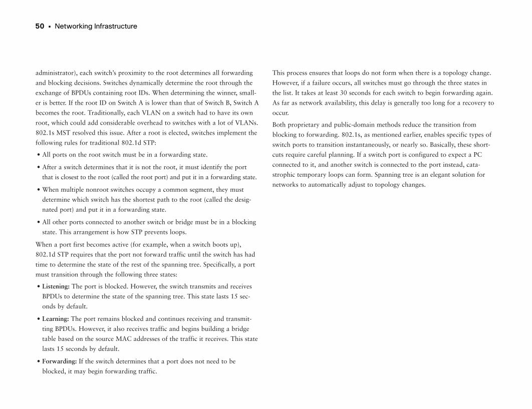
50 • Networking Infrastructure
administrator), each switch’s proximity to the root determines all forwarding
and blocking decisions. Switches dynamically determine the root through the
exchange of BPDUs containing root IDs. When determining the winner, small-
er is better. If the root ID on Switch A is lower than that of Switch B, Switch A
becomes the root. Traditionally, each VLAN on a switch had to have its own
root, which could add considerable overhead to switches with a lot of VLANs.
802.1s MST resolved this issue. After a root is elected, switches implement the
following rules for traditional 802.1d STP:
• All ports on the root switch must be in a forwarding state.
• After a switch determines that it is not the root, it must identify the port
that is closest to the root (called the root port) and put it in a forwarding state.
• When multiple nonroot switches occupy a common segment, they must
determine which switch has the shortest path to the root (called the desig-
nated port) and put it in a forwarding state.
• All other ports connected to another switch or bridge must be in a blocking
state. This arrangement is how STP prevents loops.
When a port first becomes active (for example, when a switch boots up),
802.1d STP requires that the port not forward traffic until the switch has had
time to determine the state of the rest of the spanning tree. Specifically, a port
must transition through the following three states:
• Listening: The port is blocked. However, the switch transmits and receives
BPDUs to determine the state of the spanning tree. This state lasts 15 sec-
onds by default.
• Learning: The port remains blocked and continues receiving and transmit-
ting BPDUs. However, it also receives traffic and begins building a bridge
table based on the source MAC addresses of the traffic it receives. This state
lasts 15 seconds by default.
• Forwarding: If the switch determines that a port does not need to be
blocked, it may begin forwarding traffic.
This process ensures that loops do not form when there is a topology change.
However, if a failure occurs, all switches must go through the three states in
the list. It takes at least 30 seconds for each switch to begin forwarding again.
As far as network availability, this delay is generally too long for a recovery to
occur.
Both proprietary and public-domain methods reduce the transition from
blocking to forwarding. 802.1s, as mentioned earlier, enables specific types of
switch ports to transition instantaneously, or nearly so. Basically, these short-
cuts require careful planning. If a switch port is configured to expect a PC
connected to it, and another switch is connected to the port instead, cata-
strophic temporary loops can form. Spanning tree is an elegant solution for
networks to automatically adjust to topology changes.
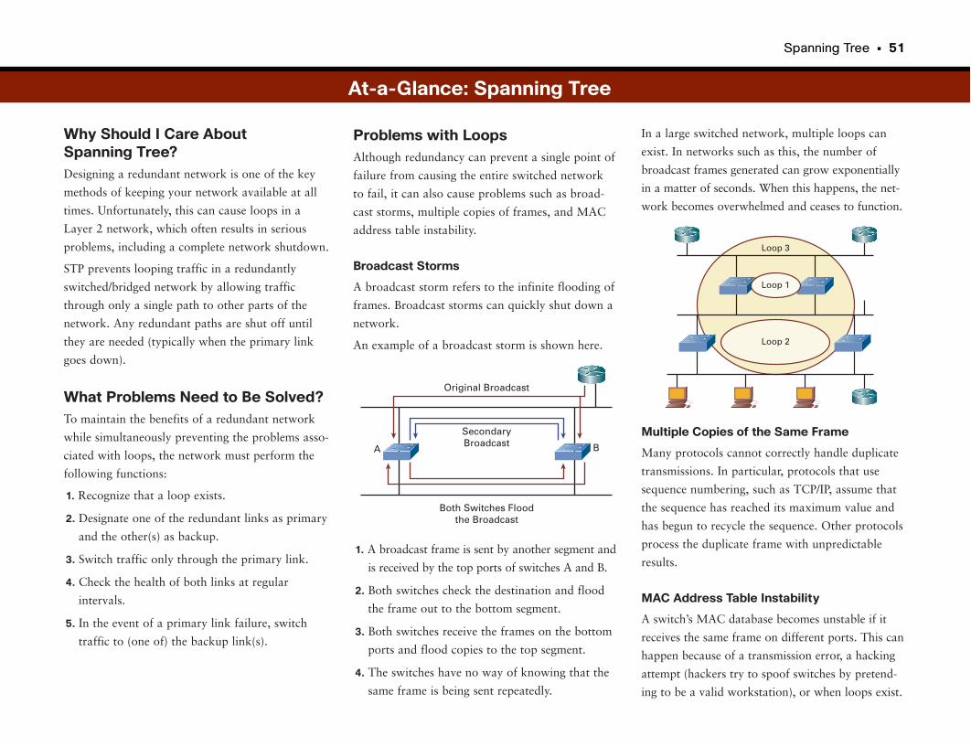
Spanning Tree • 51
Why Should I Care About Spanning Tree?Designing a redundant network is one of the key
methods of keeping your network available at all
times. Unfortunately, this can cause loops in a
Layer 2 network, which often results in serious
problems, including a complete network shutdown.
STP prevents looping traffic in a redundantly
switched/bridged network by allowing traffic
through only a single path to other parts of the
network. Any redundant paths are shut off until
they are needed (typically when the primary link
goes down).
What Problems Need to Be Solved?To maintain the benefits of a redundant network
while simultaneously preventing the problems asso-
ciated with loops, the network must perform the
following functions:
1. Recognize that a loop exists.
2. Designate one of the redundant links as primary
and the other(s) as backup.
3. Switch traffic only through the primary link.
4. Check the health of both links at regular
intervals.
5. In the event of a primary link failure, switch
traffic to (one of) the backup link(s).
In a large switched network, multiple loops can
exist. In networks such as this, the number of
broadcast frames generated can grow exponentially
in a matter of seconds. When this happens, the net-
work becomes overwhelmed and ceases to function.
Multiple Copies of the Same Frame
Many protocols cannot correctly handle duplicate
transmissions. In particular, protocols that use
sequence numbering, such as TCP/IP, assume that
the sequence has reached its maximum value and
has begun to recycle the sequence. Other protocols
process the duplicate frame with unpredictable
results.
MAC Address Table Instability
A switch’s MAC database becomes unstable if it
receives the same frame on different ports. This can
happen because of a transmission error, a hacking
attempt (hackers try to spoof switches by pretend-
ing to be a valid workstation), or when loops exist.
Problems with LoopsAlthough redundancy can prevent a single point of
failure from causing the entire switched network
to fail, it can also cause problems such as broad-
cast storms, multiple copies of frames, and MAC
address table instability.
Broadcast Storms
A broadcast storm refers to the infinite flooding of
frames. Broadcast storms can quickly shut down a
network.
An example of a broadcast storm is shown here.
1. A broadcast frame is sent by another segment and
is received by the top ports of switches A and B.
2. Both switches check the destination and flood
the frame out to the bottom segment.
3. Both switches receive the frames on the bottom
ports and flood copies to the top segment.
4. The switches have no way of knowing that the
same frame is being sent repeatedly.
Original Broadcast
SecondaryBroadcast
Both Switches Floodthe Broadcast
A B
At-a-Glance: Spanning Tree
Loop 3
Loop 2
Loop 1
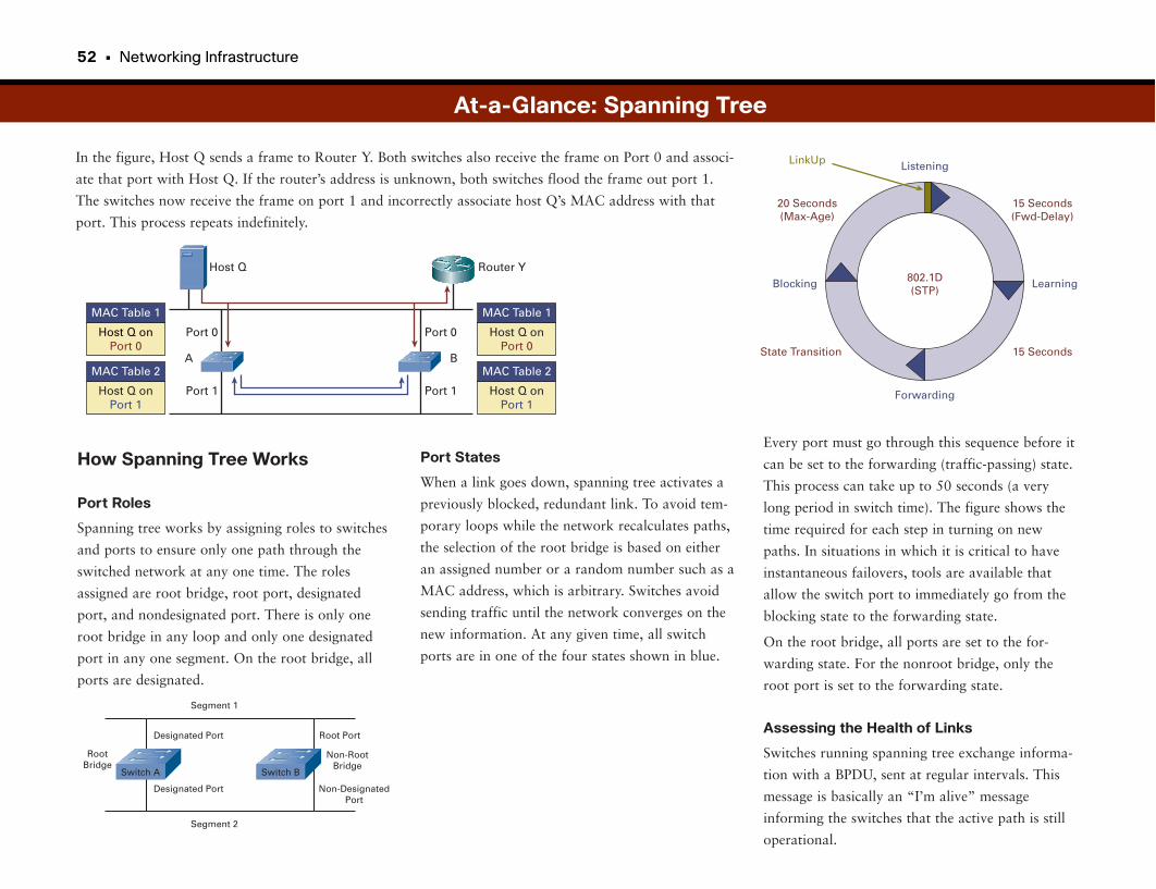
52 • Networking Infrastructure
In the figure, Host Q sends a frame to Router Y. Both switches also receive the frame on Port 0 and associ-
ate that port with Host Q. If the router’s address is unknown, both switches flood the frame out port 1.
The switches now receive the frame on port 1 and incorrectly associate host Q’s MAC address with that
port. This process repeats indefinitely.
Every port must go through this sequence before it
can be set to the forwarding (traffic-passing) state.
This process can take up to 50 seconds (a very
long period in switch time). The figure shows the
time required for each step in turning on new
paths. In situations in which it is critical to have
instantaneous failovers, tools are available that
allow the switch port to immediately go from the
blocking state to the forwarding state.
On the root bridge, all ports are set to the for-
warding state. For the nonroot bridge, only the
root port is set to the forwarding state.
Assessing the Health of Links
Switches running spanning tree exchange informa-
tion with a BPDU, sent at regular intervals. This
message is basically an “I’m alive” message
informing the switches that the active path is still
operational.
How Spanning Tree Works
Port Roles
Spanning tree works by assigning roles to switches
and ports to ensure only one path through the
switched network at any one time. The roles
assigned are root bridge, root port, designated
port, and nondesignated port. There is only one
root bridge in any loop and only one designated
port in any one segment. On the root bridge, all
ports are designated.
At-a-Glance: Spanning Tree
Host Q onPort 0
MAC Table 1
Host Q onPort 1
MAC Table 2
Host Q onPort 1
MAC Table 2
Host Q onPort 0
MAC Table 1
Port 0
Port 1
Port 0
Port 1
A B
Host Q Router Y
Segment 1
Designated Port
Designated Port
Segment 2
RootBridge
Root Port
Non-RootBridge
Non-DesignatedPort
Switch BSwitch A
Port States
When a link goes down, spanning tree activates a
previously blocked, redundant link. To avoid tem-
porary loops while the network recalculates paths,
the selection of the root bridge is based on either
an assigned number or a random number such as a
MAC address, which is arbitrary. Switches avoid
sending traffic until the network converges on the
new information. At any given time, all switch
ports are in one of the four states shown in blue.
Listening
15 Seconds(Fwd-Delay)
Learning
15 Seconds
Forwarding
State Transition
Blocking
20 Seconds(Max-Age)
LinkUp
802.1D(STP)
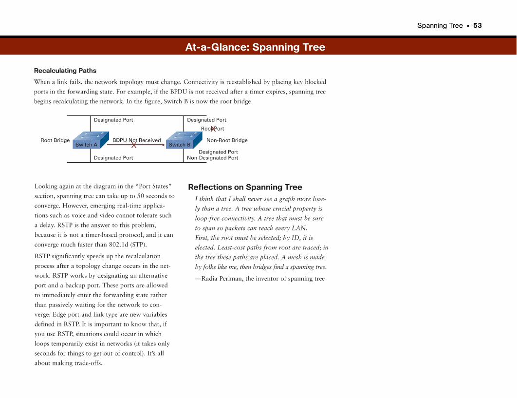
Spanning Tree • 53
Recalculating Paths
When a link fails, the network topology must change. Connectivity is reestablished by placing key blocked
ports in the forwarding state. For example, if the BPDU is not received after a timer expires, spanning tree
begins recalculating the network. In the figure, Switch B is now the root bridge.
Reflections on Spanning TreeI think that I shall never see a graph more love-
ly than a tree. A tree whose crucial property is
loop-free connectivity. A tree that must be sure
to span so packets can reach every LAN.
First, the root must be selected; by ID, it is
elected. Least-cost paths from root are traced; in
the tree these paths are placed. A mesh is made
by folks like me, then bridges find a spanning tree.
—Radia Perlman, the inventor of spanning tree
Looking again at the diagram in the “Port States”
section, spanning tree can take up to 50 seconds to
converge. However, emerging real-time applica-
tions such as voice and video cannot tolerate such
a delay. RSTP is the answer to this problem,
because it is not a timer-based protocol, and it can
converge much faster than 802.1d (STP).
RSTP significantly speeds up the recalculation
process after a topology change occurs in the net-
work. RSTP works by designating an alternative
port and a backup port. These ports are allowed
to immediately enter the forwarding state rather
than passively waiting for the network to con-
verge. Edge port and link type are new variables
defined in RSTP. It is important to know that, if
you use RSTP, situations could occur in which
loops temporarily exist in networks (it takes only
seconds for things to get out of control). It’s all
about making trade-offs.
BDPU Not Received
Designated Port
Designated Port
Root Bridge
Root Port
Non-Root Bridge
Non-Designated Port
Designated Port
X
X
Designated PortSwitch BSwitch A
At-a-Glance: Spanning Tree
Routing
RoutersWhereas switches and bridges operate at OSI Layer 2 (the data link layer),
routers primarily operate at OSI Layer 3 (the network layer). Like bridging,
the primary act of routing involves moving packets across a network from a
source to a destination. The difference involves the information that is used to
make the forwarding decisions. Routers make decisions based on network
layer protocols such as Internet Protocol (IP) and Novell NetWare
Internetwork Packet Exchange (IPX).
Routing gained popularity in the mid- to late 1980s as a result of internet-
works growing beyond the capability of bridges. Before this popularity, net-
works were relatively small and isolated, and bridges could handle the jobs of
forwarding and segmentation. However, as networks grew, routers facilitated
larger scaling and more intelligent growth across wider physical distances.
Although routers are more expensive and complex than bridges, routing is the
core of the Internet today.
Routers Talk Among Themselves to Find RoutesRouting involves two processes: determining optimal routing paths through a
network, and forwarding packets along those paths. Routing algorithms make
the optimal path determination. As they determine routes, tables on the router
store the information. Routers communicate with each other and maintain
their routing tables through the exchange of messages over the network.
Routing updates are one particular type of message. A routing update contains
all or part of another router’s routing table and allows each router to build a
detailed picture of the overall network topology.
Routing algorithms fill routing tables with various types of information. The
primary piece of information relevant to routing is the next hop. Next-hop
associations tell a router that it can reach a particular destination by sending a
packet to a particular router representing the next hop on the way to its final
destination.
The process of exchanging information between routers is done using a rout-
ing protocol. Put simply, a routing protocol is a series of messages that routers
use to exchange information about whether particular links are up or down,
and about other next-hop routers in the network. Three of the most common
routing protocols in use today are Open Shortest Path First (OSPF), Enhanced
Interior Gateway Routing Protocol (EIGRP), and Border Gateway Protocol
(BGP).
Routers Route PacketsWhen a router receives a packet, it attempts to associate the destination net-
work address in the packet to an appropriate next hop in its routing table. In
addition to next-hop associations, routers store other pertinent information in
routing tables. For multiple paths to a destination, a routing table might con-
tain information that allows the router to determine the desirability of one
path over another.
After a router determines an optimal path for a packet, it must forward the
packet toward the destination. The process of a router moving a packet from
its received port to the outgoing destination port is called switching. Although
the process of switching a packet on a router is similar to that of a Layer 2
switch, the decision criteria and the actual handling of the packet are different.
When a computer determines that it must send a packet to another host, it
specifies in the packet how to reach the destination network. If the destination
is unknown, the router typically drops the packet. If the destination is known,
the router changes the destination physical address in the packet to contain
that of the next hop. The router then transmits the packet out the destination
interface.
The next hop can be either the final destination or another router. Each router in
the process performs the same operation. As the packet moves through the net-
work, each router modifies the physical address stored in the packet but leaves
the network address untouched (because it determines the final destination).
56 • Networking Infrastructure
Routers Bridge and Switches RouteIn an ideal world, everything does what it is defined to do. This is not the case
with network devices. Routers can provide bridging functionality, and switches
are quickly becoming the high-density port, high-speed router of the campus.
Network devices, including switches and routers, make forwarding decisions
on OSI layers higher than the network layer. For example, routers can provide
firewall functionality in which the router inspects Layer 4 packet information,
and switches such as content switches can perform forwarding decisions based
on Layer 5 through 7 packet information (such as the URL in an HTTP packet).
Routing • 57
Why Should I Care About Routing?Routing is one of the fundamental aspects of net-
working. Routers can learn possible routes (rather
than having to have the route manually configured
and constantly updated). This is one of the primary
reasons that ARPANET, which originally connect-
ed seven sites, was able to scale exponentially into
the modern Internet in only a few years. Many
routers today have address tables with more than
100,000 entries, and they are updated constantly.
What Problems Need to Be Solved?Routed networks are often large and complex, and
it would be prohibitively difficult to manage and
update network information on all routers all the
time. To account for this, several algorithms have
been developed. These algorithms allow the routers
to learn about the network and then make deci-
sions based on that information.
To learn paths (or routes) through a network and
then decide where to send packets, a router must
know the following information:
• Destination address: This is typically the IP
address of the data’s (packet) destination.
• Source address: The router also needs to know
where the information came from (typically an
IP address).
• Possible routes: These are likely routes that can
get information from the present location or
source to some other location (the destination or
closest known point).
Static Versus DynamicRouters must learn about the network around
them to determine where to send packets. This
information can be either manually entered (static
routes) or learned from other routers in the net-
work (dynamic routes):
• Static routes: When a network administrator
manually enters information about a route, it is
considered a static route. This information can
be changed only by a network administrator (in
other words, the router doesn’t learn about net-
work events). Static routes allow for tight con-
trol of packets but become difficult to maintain
and are prone to human error. However, static
routes may be used to work around a temporary
problem or for performance enhancement.
• Dynamic routes: Routers on a network can
learn about possible routes and current route
status from other routers in the network. Routes
learned in this way are called dynamic routes.
Unlike static routes, any changes in the network
are learned without administrative intervention
and are automatically propagated throughout
the network.
Flat Versus HierarchicalWith flat networks, all routers must keep track of
all other routers on the network. As networks
grow, the amount of information contained in the
routing tables becomes larger and larger.
• Best route: Routers also must know the best
(“best” can mean many things) path to the
intended destination.
• Status of routes: Routers also keep track of the
current state of routes to ensure timely delivery
of information.
What Exactly Does “Best” Mean?Routers often make decisions about the best possi-
ble path to get information from a source to a des-
tination. “Best” is loosely defined; it depends on
what the network values. These measurements of
value are called metrics. The network administra-
tor determines which metrics the network values.
Here are several metrics:
• Hop count: How many times a packet goes
through a router.
• Delay: The amount of time required to reach the
destination.
• Reliability: The bit error rate of each network
link.
• Maximum Transmission Unit (MTU): The max-
imum message length (or packet size) allowed
on the path.
• Cost: An arbitrary value based on a network
administrator-determined value. Usually some
combination of other metrics.
At-a-Glance: Routing
Router
D1D2D4
All Others
D1D2D4D1
1111
Next Hops
Routing Table D3
Router
A2A3A4
Any BAny CAny D
A2A3A4B1B2B3
111111
Next Hops
Routing Table A1
Router
C2C3C4
Any AAny BAny D
C2C3C4A1B1D1
111111
Next Hops
Routing Table C3
A2 A3
A1
C1
A4
C2 C3 C4
D2
D3
D4
B2
B3
B4
B1D1
58 • Networking Infrastructure
Although this method is simple, it can result in poor network performance as the
number of routing updates grows exponentially with each new router.
Hierarchical networks segment routers into logical groupings. This simplifies
routing tables and greatly reduces overheard traffic.
Intradomain Versus InterdomainIntradomain and interdomain routing can be easily understood in the context of
large-scale hierarchical networks. In this regard, think of each segment as its
own autonomous network. Within each autonomous network, intradomain
routing protocols (also called Interior Gateway Protocols [IGP]) are used to
exchange routing information and forward packets. Interdomain routing proto-
cols (also called Exterior Gateway Protocols [EGP]) are used between
autonomous networks. This distinction is made because there are different per-
formance requirements for internal and external networks.
Distance Vector Versus Link-StateThe two main classes of routing are distance vector routing and link-state routing.
With distance vector routing, also called “routing by rumor,” routers share their
routing table information with each other. Each router provides and receives
updates from its direct neighbor. In the figure, Router B shares information with
Routers A and C. Router C shares routing information with Routers B and D. A
distance vector describes the direction (port) and the distance (number of hops
or other metric) to some other router. When a router receives information from
another router, it increments whatever metric is being used. This process is called
distance accumulation. Routers using this method know the distance between
any two points in the network, but they do not know the exact topology of an
internetwork.
At-a-Glance: Routing
Router
ABCDEFGHIJKLMNP
MMMMMMMMMMMMMNO
11112221222122
Next Hop Hops
Routing Table O
Router
BCDEFGHIJKLMNOP
BCDEEEEIIII
MMMM
111122212221222
Next Hop Hops
Routing Table A
Router
ABCDEFGHJKLMNOP
AAAAEEEEJKLMMMM
111122212221222
Next Hop Hops
Routing Table I
B C
A
I
D
J K L
N
O
P
F
G
H
EM
Routing • 59
How Information Is Discovered withDistance Vectors
Network discovery is the process of learning about
nondirectly connected routers. During network dis-
covery, routers accumulate metrics and learn the
best paths to various destinations in the network.
In the figure, each directly connected network has
a distance of 0. Router A learns about other net-
works based on information it receives from
Router B. Routers increment the distance metric
for any route learned by an adjacent router. In
other words, Router A increments by 1 any dis-
tance information it learns about other routers
from Router B.
As more time goes by, the router learns more
about the network and can process packets
more efficiently.
Link-State RoutingWith link-state routing (also known as shortest
path first [SPF]), each router maintains a database
of topology information for the entire network.
Link-state routing provides better scaling than
distance-vector routing, because it sends updates
only when there is a change in the network, and
then it sends only information specific to the
change that occurred. Distance vector uses regular
updates and sends the whole routing table every
time. Link-state routing also uses a hierarchical
model, limiting the scope of route changes that
occur.
B CA D
At-a-Glance: Routing
Table ADest. Port Distance
Table BDest. Port Distance
Table CDest. Port Distance
Table DDest. Port Distance
Table ADest. Port Distance
Table BDest. Port Distance
Table CDest. Port Distance
Table DDest. Port Distance
B 1 0 A 0 0C 1 0
B 0 0D 1 0
C 0 0
Table ADest. Port Distance
Table BDest. Port Distance
Table CDest. Port Distance
Table DDest. Port Distance
B 1 0 A 0 0C 1 0
A 0 1B 0 0
B 0 1C 1 1
D 1 1 D 1 0C 0 0
0 1 0 1 0 1 0 1
Info Exchange
Info Exchange
Time 0
Time 1
Time 2
B CA D
Routers and Switches
Router
• Connects Switches to Each Other• Operates at Layer 3• Comparatively Smart• Slow• Expensive Per Port
Switch
• Connects End Points to the Network• Operates at Layer 2• Fast• Not As Smart• Inexpensive Per Port
10.0.1.x
10.0.3.x
10.0.2.x
Traffic on a given subnet (from a 10.0.3.x endpointto another 10.0.3.x. endpoint) is ignoredby the router.
10.0.3.1
10.0.3.2
10.0.3.3
10.0.3.4
10.0.3.5
10.0.3.6
The switch looksup the destinationaddress of data frames in a table. If the addressis known, the frame is sent to a specified port (this is called filtering).
If the destination is unknown,the data frame is sent to all ports (this is called flooding).
If the destination network of a packet is unknown, the packet is routed to thenext closest address. If the destinationof the packet is known, the packet isrouted to the port associated with thatnetwork.
There are now routers that switch, and switches that route. So, the distinctions are getting blurred.
Routing and Switching
60 • Networking Infrastructure
Routing • 61
Connectivity
Switch
• Connects Devices Together Quickly• Connects End Points to the Network
Router
• Connects Switches to Each Other• Connects Buildings
Routing and Switching
Part III
Network DesignParts I and II looked at how computers communicate, with the OSI model as well as switching and rout-
ing protocols. The good news is that pretty much anything you put on a network is covered by these prin-
ciples, so all a designer has to do is apply them. The bad news is that the networks can get big—make
that very big, as in tens of thousands of routers and switches connecting hundreds of thousands of
devices.
To ensure that the network can continue to operate on a massive scale, some good design practices must
be put into place. Part III covers some of these principles, which almost always apply to enterprise-scale
networks.
The first thing we need to design is the main campus or headquarters network. “Campus Networks and
Hierarchical Design” shows you how a local network is constructed for a large company.
As soon as the main campus network is up and running, a company will likely want to communicate with
other smaller sites using wide-area networks (WAN). “WAN Network Design” covers a number of WAN
technologies, including Frame Relay, Asynchronous Transfer Mode (ATM), and MPLS.
We also explore broadband technologies. With the advent of high-speed Internet, many enterprise employ-
ees can telecommute without losing access to their enterprise applications. This section shows how ISDN,
cable, and DSL work. Wireless is also a consideration here, but we’ll save the wireless discussion for later
in this book.
We close the WAN discussion with the section “Optical Technologies.” Optical technologies use light sig-
nals rather than electrical impulses, which creates a different set of challenges to overcome. Optical is
becoming increasingly popular because of its incredible bandwidth, so it’s worth looking at (no pun
intended).
Finally, you want the data you send over the WAN to go somewhere, and that somewhere is often a
branch office. At one time branch offices were often handled with nothing more than a router supported
by a local “IT guy.” Today, branch offices are often as complicated as headquarters networks, with some
interesting challenges as far as data and application access.
Campus Networks and 65
Hierarchical Design
WAN Network Design 71
Broadband Technologies 85
Virtual Private Networks 93
Optical Technologies 107
Branch Office Network Designs 113
Campus Networks and Hierarchical Design
If these layers are a little hard to follow, think of them as you would a nation-
al mail system. Access is like your local post office, where everyone first “con-
nects” to send their letters. Distribution is like a regional mail center that
receives mail from lots of neighborhood post offices, sorting and prepping
them to move on in the mail system. Some local mail may be routed within the
region, back to local post offices in the next town. Others may need to go
cross-country to other regional mail centers. The core is like the backbone
shipping network between postal regions. It carries mail from state to state in
large shipping containers, such as trucks and planes. It must be fast, efficient,
and able to handle large capacity.
The distribution and core layers of the network provide vital services by aggre-
gating groups of users and services. Therefore, if a distribution or core device
dies, this can affect large communities of users. For this reason, reducing the
chance of failure in these layers reduces and possibly prevents unnecessary and
unplanned outages. Redundant network paths, redundant hardware, and fault-
tolerant-related network protocols (such as Hot Standby Router Protocol
[HSRP]) all help a network recover quickly (and hopefully transparently to the
users) after a failure.
Companies prefer to reduce the number of routed protocols traversing the core
layer. In the early 1990s, before the massive popularity of TCP/IP and the
Internet, backbones carried the predominant protocols of the day: Novell,
DECnet, AppleTalk, NetBIOS, and Banyan VINES. Having so many protocols
complicated design issues. As TCP/IP became the de facto networking proto-
col, companies worked to eliminate the non-IP traffic from the core.
Building Networks for Ease of UseCampus, as it applies to networking, typically describes the routers, switches,
network appliances, and servers that make up the networking infrastructure
for a set of buildings located in close proximity. A campus can be the manu-
facturing site of a large corporation, the headquarters for a bank, or a college
campus.
A design goal for campus networks is to separate buildings, floors, work-
groups, and server farms into smaller Layer 3 groups to prevent network faults
from affecting large populations of users. Layer 3 routers provide natural
boundaries against debilitating network problems such as broadcast storms
and loops. Over time, the hierarchical approach to network design has proven
the most effective. The three primary layers of a hierarchical campus are as
follows:
• Core (sometimes called the backbone): The core is the central thoroughfare
for corporate traffic. All other parts of the network eventually feed into the
core. You should design the core to switch packets as quickly as possible.
This level should not include operations that might slow the switching of
the packet: The distribution layer should handle any packet manipulation or
filtering that needs to occur.
• Distribution: The distribution layer provides policy-based connectivity and
boundaries between the access layers and the core. For example, a building
of 20 floors might have a distribution network that connects each floor with
the core. It is at this layer that packets should be filtered or manipulated.
Therefore, as soon as packets are “prepped,” the core simply needs to
switch them quickly to the destination distribution location.
• Access: The access layer provides user access to the network. It is at this
point that users are permitted (or denied) access into the corporate network.
Typically, each person sitting at a desk has a cable that runs to a wiring
closet and connects to a switch; hence, this level is where the user accesses
the network.
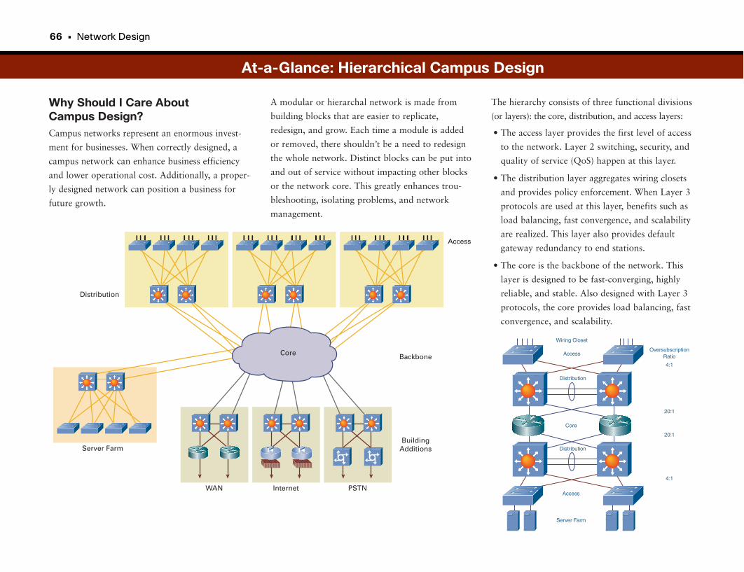
66 • Network Design
Why Should I Care About Campus Design?Campus networks represent an enormous invest-
ment for businesses. When correctly designed, a
campus network can enhance business efficiency
and lower operational cost. Additionally, a proper-
ly designed network can position a business for
future growth.
The hierarchy consists of three functional divisions
(or layers): the core, distribution, and access layers:
• The access layer provides the first level of access
to the network. Layer 2 switching, security, and
quality of service (QoS) happen at this layer.
• The distribution layer aggregates wiring closets
and provides policy enforcement. When Layer 3
protocols are used at this layer, benefits such as
load balancing, fast convergence, and scalability
are realized. This layer also provides default
gateway redundancy to end stations.
• The core is the backbone of the network. This
layer is designed to be fast-converging, highly
reliable, and stable. Also designed with Layer 3
protocols, the core provides load balancing, fast
convergence, and scalability.
A modular or hierarchal network is made from
building blocks that are easier to replicate,
redesign, and grow. Each time a module is added
or removed, there shouldn’t be a need to redesign
the whole network. Distinct blocks can be put into
and out of service without impacting other blocks
or the network core. This greatly enhances trou-
bleshooting, isolating problems, and network
management.
At-a-Glance: Hierarchical Campus Design
Access
Backbone
Distribution
BuildingAdditionsServer Farm
PSTNInternetWAN
Core
Server Farm
Wiring Closet
Distribution
AccessOversubscription
Ratio
4:1
20:1
20:1
4:1
Access
Distribution
Core
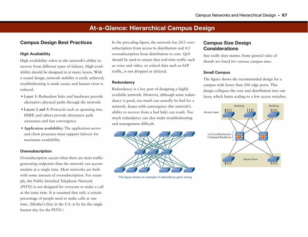
Campus Networks and Hierarchical Design • 67
Campus Design Best Practices
High Availability
High availability refers to the network’s ability to
recover from different types of failures. High avail-
ability should be designed in at many layers. With
a sound design, network stability is easily achieved,
troubleshooting is made easier, and human error is
reduced.
• Layer 1: Redundant links and hardware provide
alternative physical paths through the network.
• Layers 2 and 3: Protocols such as spanning tree,
HSRP, and others provide alternative path
awareness and fast convergence.
• Application availability: The application server
and client processes must support failover for
maximum availability.
Oversubscription
Oversubscription occurs when there are more traffic-
generating endpoints than the network can accom-
modate at a single time. Most networks are built
with some amount of oversubscription. For exam-
ple, the Public Switched Telephone Network
(PSTN) is not designed for everyone to make a call
at the same time. It is assumed that only a certain
percentage of people need to make calls at one
time. (Mother’s Day in the U.S. is by far the single
busiest day for the PSTN.)
Campus Size DesignConsiderationsSize really does matter. Some general rules of
thumb are listed for various campus sizes.
Small Campus
The figure shows the recommended design for a
campus with fewer than 200 edge ports. This
design collapses the core and distribution into one
layer, which limits scaling to a few access switches.
In the preceding figure, the network has 20:1 over-
subscription from access to distribution and 4:1
oversubscription from distribution to core. QoS
should be used to ensure that real-time traffic such
as voice and video, or critical data such as SAP
traffic, is not dropped or delayed.
Redundancy
Redundancy is a key part of designing a highly
available network. However, although some redun-
dancy is good, too much can actually be bad for a
network. Issues with convergence (the network’s
ability to recover from a bad link) can result. Too
much redundancy can also make troubleshooting
and management difficult.
At-a-Glance: Hierarchical Campus Design
This figure shows an example of redundancy gone wrong.
Building Building
Access Layer
L3 Core/DistributionCollapsed Backbone
Server Farm
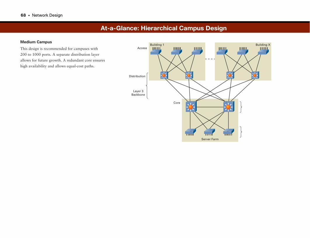
68 • Network Design
Medium Campus
This design is recommended for campuses with
200 to 1000 ports. A separate distribution layer
allows for future growth. A redundant core ensures
high availability and allows equal-cost paths.
At-a-Glance: Hierarchical Campus Design
Server Farm
Building 1 Building X
Core
Access
Distribution
Layer 3Backbone
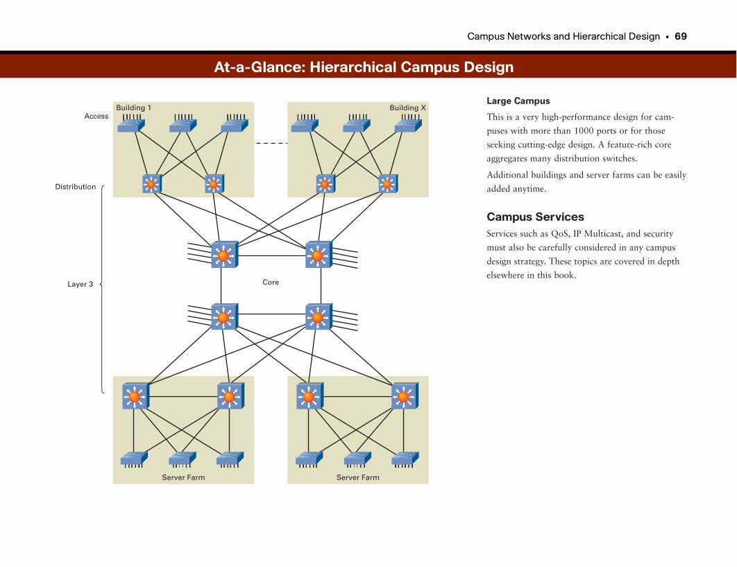
Campus Networks and Hierarchical Design • 69
Large Campus
This is a very high-performance design for cam-
puses with more than 1000 ports or for those
seeking cutting-edge design. A feature-rich core
aggregates many distribution switches.
Additional buildings and server farms can be easily
added anytime.
Campus ServicesServices such as QoS, IP Multicast, and security
must also be carefully considered in any campus
design strategy. These topics are covered in depth
elsewhere in this book.
At-a-Glance: Hierarchical Campus Design
Building 1 Building X
Core
Access
Distribution
Layer 3
Server Farm Server Farm

WAN Network Design
Moving Traffic Across the Street and the WorldHow does a company connect the network in its New York office to the net-
work in its Los Angeles office? It doesn’t make sense to run a private cable
across the U.S. Instead, the company subscribes to wide-area services. A wide-
area network (WAN) is a network that covers a broad geographic area and
often uses transmission facilities provided by service providers. WAN function-
ality occurs at Layers 1 to 3 in the Open Systems Interconnection (OSI) refer-
ence model.
The bicoastal company just mentioned would contact its service provider to
purchase WAN connectivity between the offices. WAN services are leased from
service providers that charge either a monthly flat fee or fees based on the
amount of data transmitted. The more bandwidth required for a WAN circuit,
the greater the usage charges are. Service providers can use a single national
network to provide WAN services for many different corporate customers. In
this way it is not necessary for each company to physically connect every office
to every other office. Imagine the cross-country cables involved in connecting
just one large company, let alone thousands.
WAN ServicesThree types of transport are used with WANs:
• Point-to-point: Also known as leased line, a point-to-point connection is a
pre-established link from one site, across a service provider’s network, to a
remote site. The carrier establishes the point-to-point link for the customer’s
private use.
• Circuit switching: A service provider establishes a dedicated physical circuit
into a carrier network for two or more connections. Unlike point-to-point,
which has exactly two sites connected to a single connection, multiple sites
privately connect into a carrier’s switched network to communicate with
each other. Circuit switching operates like a normal telephone call. ISDN is
an example of circuit-switched WAN technology.
• Packet switching: This type of transport is similar to circuit switching in
that multiple sites privately connect into a carrier-switched network.
However, packet switching involves the statistical multiplexing of packets
across shared circuits. Frame Relay, Multiprotocol Label Switching (MPLS),
broadband DSL and cable, and Metro Ethernet are all examples of packet
switching.
Some WAN technologies, such as Frame Relay and Asynchronous Transfer
Mode (ATM), use virtual circuits to ensure reliable communication between
two network devices. The two types of virtual circuits are switched virtual cir-
cuits (SVC) and permanent virtual circuits (PVC). An SVC is dynamically
established on demand and is torn down when transmission is complete. A
connection uses SVCs when data transmission between devices is sporadic. A
PVC is a permanently established logical circuit and is useful for connections
between two devices in which data transfer is constant.
WAN dialup services are available as alternative backup technologies for tradi-
tional WAN services. As the name implies, dialup services use plain old tele-
phone service (POTS) and are inexpensive (but relatively slow) alternatives
when the main WAN service goes down. Cisco routers offer two popular types
of dialup services: dial-on-demand routing (DDR) and dial backup. DDR can
be triggered automatically when the primary connection goes down or when a
traffic threshold is reached. Dial backup initiates a dial connection to another
router after it determines that the primary WAN service is unavailable. The
dial connection remains active until the WAN service returns.
Integrated Services Digital NetworkIntegrated Services Digital Network (ISDN) is a set of technologies developed
to carry voice, video, and data across telephone networks. ISDN operates at
Layers 1 to 3 in the OSI reference model. ISDN was the first broadband serv-
ice deployed in the home. It operated at two to four times the speed of the
modem technologies of the day and provided “always-on” connectivity com-
pared to modem dialup. For many years ISDN received a lot of hype that it
never quite lived up to. Eventually it was dealt a death blow as far as home
use with the advent of DSL and high-speed cable services. However, it is still in
use in some businesses, so it’s worth a quick look here.
72 • Network Design
Frame RelayFrame Relay is a packet-switched WAN service that operates at the physical
and logical layers of the OSI reference model. Frame Relay was originally
designed to operate over ISDN but today operates over a variety of network
interfaces. Typical communication speeds for Frame Relay are between 56
kbps and 2 Mbps (although lower and higher speeds are supported). Frame
Relay provides connection-oriented services using virtual circuits. A Frame
Relay virtual circuit is a logical connection between two data terminal equip-
ment (DTE) devices across a Frame Relay packet-switched network. A data-
link connection identifier (DLCI) uniquely identifies each virtual circuit. You
can multiplex multiple virtual circuits on a single physical circuit.
Frame Relay switched networks provide simple congestion-notification mecha-
nisms. Frame Relay switching equipment can mark a Frame Relay packet with
front-end congestion notification (FECN) or back-end congestion notification
(BECN). The equipment marks the packets with a FECN or BECN if conges-
tion occurs during the transmission of the packet. The DTE equipment at the
other end of a circuit notices whether a packet has experienced congestion and
notifies a higher layer that congestion has occurred. Additionally, the equip-
ment can mark a packet as discard eligible (DE) to indicate that it is less
important, which means that it can be dropped if congestion occurs.
ATMATM is a standard for cell-based relay that carries voice, video, and data in
small, fixed-size cells. ATM networks are connection-oriented networks that
combine the benefits of circuit switching (guaranteed capacity and constant
transmission delay) with those of packet switching (flexibility and efficiency for
intermittent traffic). ATM transmits at speeds from a few Mbps to many Gbps.
High-speed ATM circuits typically require optic-fiber cables to transmit such
high speeds. Speeds of these circuits are characterized as “Optical Carrier”
class and are represented as OC-number. The number represents the multiple
of the base OC-1 standard circuit, which can carry 51.84 Mbps. Common
circuit speeds are OC-3 (155.52 Mbps), OC-12 (622.08 Mbps), and OC-192
(9953.28 Mbps, or roughly 10 Gbps).
Traditional circuit-based networks use time-division multiplexing (TDM), in
which users are assigned a predetermined time slot; no other device can trans-
mit during this time slot. If a station has a lot of data to send, it can transmit
only during its time slot, even if the other time slots are empty. Conversely, if
the station has nothing to transmit, the time slot is sent empty and is wasted.
This arrangement is called synchronous transmission.
ATM is asynchronous, meaning that time slots are available on demand. This
allows for a more efficient use of available bandwidth. ATM uses single-sized
cells (as opposed to the variable-sized frames in Frame Relay), which have 53
bytes. Computers usually define things in powers of 2 or 8. The 53-byte cell
size represents a compromise between the phone-standards folks and the data-
standards folks.
ATM networks have two devices: ATM switches and ATM endpoints. ATM
switches accept cells from an endpoint or another switch, evaluate the cell
header, and quickly forward the cell out another interface toward the destina-
tion. An ATM endpoint contains an ATM network interface adapter and is
responsible for converting digital data into cells and back again. Examples of
ATM endpoints include workstations, LAN switches, routers, and video coder-
decoders (codecs).
ATM networks can mark traffic after it is converted from its original data for-
mat to require different types of handling. Some traffic, such as voice and
video, must be transferred through the network at regular intervals with little
variation in delay. Otherwise, the destination receives low-quality voice or
video transmission. Data traffic is less sensitive to network delays and can be
handled differently.
To ensure the appropriate delivery for each of these traffic types, ATM devices
employ QoS mechanisms that involve reserving bandwidth, shaping traffic to
meet the reserved bandwidth, and policing traffic that exceeds the reservation.
WAN Network Design • 73
MPLSMPLS is a highly efficient WAN service that companies are quickly adopting
either as a replacement for legacy Frame Relay and ATM WANs or as a sec-
ond high-speed WAN service. MPLS is discussed in more depth in a later sec-
tion.
BroadbandIncreasingly, companies are leveraging cable, DSL, and other types of broadband
Internet services to deploy WAN services. They offer low-cost, high-bandwidth
connectivity that is often suitable for small branch office locations, such as
retail stores, small insurance office branches, and gas stations and convenience
stores. Broadband services are discussed in more depth in a later section.
Virtual Private Networks (VPN)A VPN is a secured connection between two devices over a shared, unsecured
network. VPNs have been used for some time for mobile devices such as lap-
tops to connect to their corporate headquarters over the Internet. This is typi-
cally called a remote-access VPN. Encryption provides security so that no one
else on the Internet can eavesdrop on the data being sent back and forth.
Increasingly, companies are taking advantage of VPNs to also connect branch
offices to headquarters locations over the Internet, called a site-to-site VPN.
Site-to-site VPNs can be a very cost-effective way to connect relatively small
locations to corporate headquarters over Internet services, such as broadband
cable and DSL. VPNs are also used to some degree to authenticate users to
local access points in a wireless environment. VPNs are addressed in a bit
more depth in a later section.
WAN DevicesNumerous types of devices are associated with WAN service delivery. The first
is a WAN switch. Usually located in a carrier’s network, a WAN switch is a
multiport internetworking device whose job is moving traffic from source to
destination. Routers at the customer sites attach to the edges of the carrier’s
switched network (for Frame Relay and ATM). WAN switches operate at
Layer 2, the data link layer, of the OSI model.
For many packet-switched services, often a WAN router is used at both the
access location, often called the Customer Premises Equipment (CPE), and
the nearest connectivity location of the WAN service provider, often called the
Point of Presence (PoP). Modern packet-switched services, such as MPLS,
broadband, and the Internet, rely on very large, very high-speed routers to
route traffic across the service provider network between PoPs. These routers
form the backbone of the modern Internet and global WAN connectivity serv-
ices and are sometimes called core routers. Routers sitting at the edges of the
network, providing WAN access to businesses, are often called edge routers.
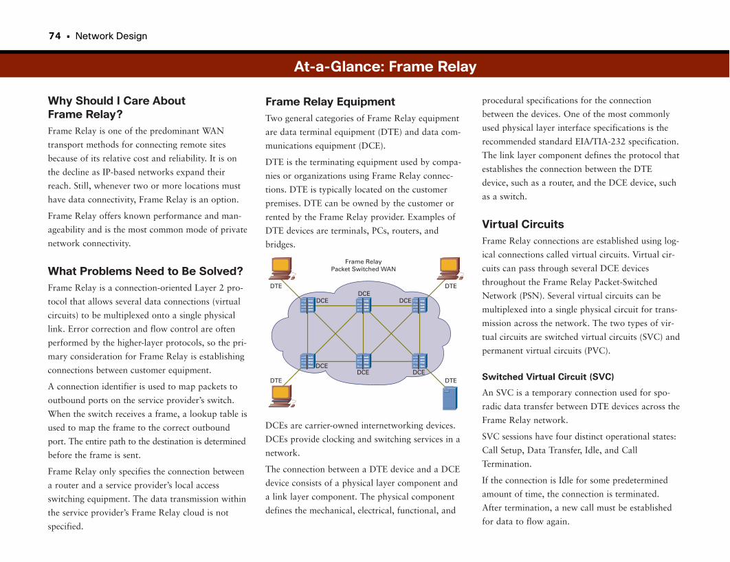
74 • Network Design
Why Should I Care About Frame Relay?Frame Relay is one of the predominant WAN
transport methods for connecting remote sites
because of its relative cost and reliability. It is on
the decline as IP-based networks expand their
reach. Still, whenever two or more locations must
have data connectivity, Frame Relay is an option.
Frame Relay offers known performance and man-
ageability and is the most common mode of private
network connectivity.
What Problems Need to Be Solved?Frame Relay is a connection-oriented Layer 2 pro-
tocol that allows several data connections (virtual
circuits) to be multiplexed onto a single physical
link. Error correction and flow control are often
performed by the higher-layer protocols, so the pri-
mary consideration for Frame Relay is establishing
connections between customer equipment.
A connection identifier is used to map packets to
outbound ports on the service provider’s switch.
When the switch receives a frame, a lookup table is
used to map the frame to the correct outbound
port. The entire path to the destination is determined
before the frame is sent.
Frame Relay only specifies the connection between
a router and a service provider’s local access
switching equipment. The data transmission within
the service provider’s Frame Relay cloud is not
specified.
procedural specifications for the connection
between the devices. One of the most commonly
used physical layer interface specifications is the
recommended standard EIA/TIA-232 specification.
The link layer component defines the protocol that
establishes the connection between the DTE
device, such as a router, and the DCE device, such
as a switch.
Virtual CircuitsFrame Relay connections are established using log-
ical connections called virtual circuits. Virtual cir-
cuits can pass through several DCE devices
throughout the Frame Relay Packet-Switched
Network (PSN). Several virtual circuits can be
multiplexed into a single physical circuit for trans-
mission across the network. The two types of vir-
tual circuits are switched virtual circuits (SVC) and
permanent virtual circuits (PVC).
Switched Virtual Circuit (SVC)
An SVC is a temporary connection used for spo-
radic data transfer between DTE devices across the
Frame Relay network.
SVC sessions have four distinct operational states:
Call Setup, Data Transfer, Idle, and Call
Termination.
If the connection is Idle for some predetermined
amount of time, the connection is terminated.
After termination, a new call must be established
for data to flow again.
Frame Relay EquipmentTwo general categories of Frame Relay equipment
are data terminal equipment (DTE) and data com-
munications equipment (DCE).
DTE is the terminating equipment used by compa-
nies or organizations using Frame Relay connec-
tions. DTE is typically located on the customer
premises. DTE can be owned by the customer or
rented by the Frame Relay provider. Examples of
DTE devices are terminals, PCs, routers, and
bridges.
DCEs are carrier-owned internetworking devices.
DCEs provide clocking and switching services in a
network.
The connection between a DTE device and a DCE
device consists of a physical layer component and
a link layer component. The physical component
defines the mechanical, electrical, functional, and
At-a-Glance: Frame Relay
Frame RelayPacket Switched WAN
DTE DTE
DTE DTEDCE
DCEDCEDCE
DCEDCE
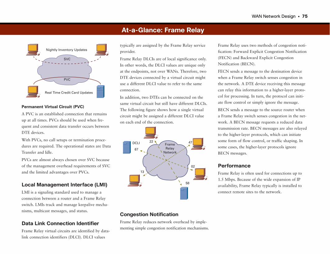
WAN Network Design • 75
Permanent Virtual Circuit (PVC)
A PVC is an established connection that remains
up at all times. PVCs should be used when fre-
quent and consistent data transfer occurs between
DTE devices.
With PVCs, no call setups or termination proce-
dures are required. The operational states are Data
Transfer and Idle.
PVCs are almost always chosen over SVC because
of the management overhead requirements of SVC
and the limited advantages over PVCs.
Local Management Interface (LMI)LMI is a signaling standard used to manage a
connection between a router and a Frame Relay
switch. LMIs track and manage keepalive mecha-
nisms, multicast messages, and status.
Data Link Connection IdentifierFrame Relay virtual circuits are identified by data-
link connection identifiers (DLCI). DLCI values
Frame Relay uses two methods of congestion noti-
fication: Forward Explicit Congestion Notification
(FECN) and Backward Explicit Congestion
Notification (BECN).
FECN sends a message to the destination device
when a Frame Relay switch senses congestion in
the network. A DTE device receiving this message
can relay this information to a higher-layer proto-
col for processing. In turn, the protocol can initi-
ate flow control or simply ignore the message.
BECN sends a message to the source router when
a Frame Relay switch senses congestion in the net-
work. A BECN message requests a reduced data
transmission rate. BECN messages are also relayed
to the higher-layer protocols, which can initiate
some form of flow control, or traffic shaping. In
some cases, the higher-layer protocols ignore
BECN messages.
PerformanceFrame Relay is often used for connections up to
1.5 Mbps. Because of the wide expansion of IP
availability, Frame Relay typically is installed to
connect remote sites to the network.
typically are assigned by the Frame Relay service
provider.
Frame Relay DLCIs are of local significance only.
In other words, the DLCI values are unique only
at the endpoints, not over WANs. Therefore, two
DTE devices connected by a virtual circuit might
use a different DLCI value to refer to the same
connection.
In addition, two DTEs can be connected on the
same virtual circuit but still have different DLCIs.
The following figure shows how a single virtual
circuit might be assigned a different DLCI value
on each end of the connection.
Congestion NotificationFrame Relay reduces network overhead by imple-
menting simple congestion notification mechanisms.
Nightly Inventory Updates
SVC
PVC
Real Time Credit Card Updates
At-a-Glance: Frame Relay
FrameRelay
Network
22 47
02
58
13
67
DCLI
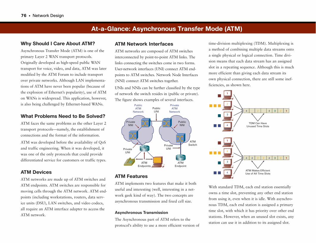
76 • Network Design
Why Should I Care About ATM?Asynchronous Transfer Mode (ATM) is one of the
primary Layer 2 WAN transport protocols.
Originally developed as high-speed public WAN
transport for voice, video, and data, ATM was later
modified by the ATM Forum to include transport
over private networks. Although LAN implementa-
tions of ATM have never been popular (because of
the explosion of Ethernet’s popularity), use of ATM
on WANs is widespread. This application, however,
is also being challenged by Ethernet-based WANs.
What Problems Need to Be Solved?ATM faces the same problems as the other Layer 2
transport protocols—namely, the establishment of
connections and the format of the information.
ATM was developed before the availability of QoS
and traffic engineering. When it was developed, it
was one of the only protocols that could provide
differentiated service for customers or traffic types.
ATM DevicesATM networks are made up of ATM switches and
ATM endpoints. ATM switches are responsible for
moving cells through the ATM network. ATM end-
points (including workstations, routers, data serv-
ice units (DSU), LAN switches, and video codecs,
all require an ATM interface adapter to access the
ATM network.
time-division multiplexing (TDM). Multiplexing is
a method of combining multiple data streams onto
a single physical or logical connection. Time divi-
sion means that each data stream has an assigned
slot in a repeating sequence. Although this is much
more efficient than giving each data stream its
own physical connection, there are still some inef-
ficiencies, as shown here.
With standard TDM, each end station essentially
owns a time slot, preventing any other end station
from using it, even when it is idle. With asynchro-
nous TDM, each end station is assigned a primary
time slot, with which it has priority over other end
stations. However, when an unused slot exists, any
station can use it in addition to its assigned slot.
ATM Network InterfacesATM networks are composed of ATM switches
interconnected by point-to-point ATM links. The
links connecting the switches come in two forms.
User-network interfaces (UNI) connect ATM end-
points to ATM switches. Network Node Interfaces
(NNI) connect ATM switches together.
UNIs and NNIs can be further classified by the type
of network the switch resides in (public or private).
The figure shows examples of several interfaces.
ATM FeaturesATM implements two features that make it both
useful and interesting (well, interesting in a net-
work geek kind of way). The two concepts are
asynchronous transmission and fixed cell size.
Asynchronous Transmission
The Asynchronous part of ATM refers to the
protocol’s ability to use a more efficient version of
At-a-Glance: Asynchronous Transfer Mode (ATM)
PrivateATM
Network
PublicATM
NetworkPublicUNI
PublicNNI
ATMSwitch
ATMEndpoint
PrivateUNI
ATMEndpoints
PrivateUNI
PrivateNNI
4 2 4 3 2 11
TDM Can HaveUnused Time Slots
11
3
4
2
4 4 2 2 4 3 2 11
ATM Makes EfficientUse of All Time Slots
11
2
3
4
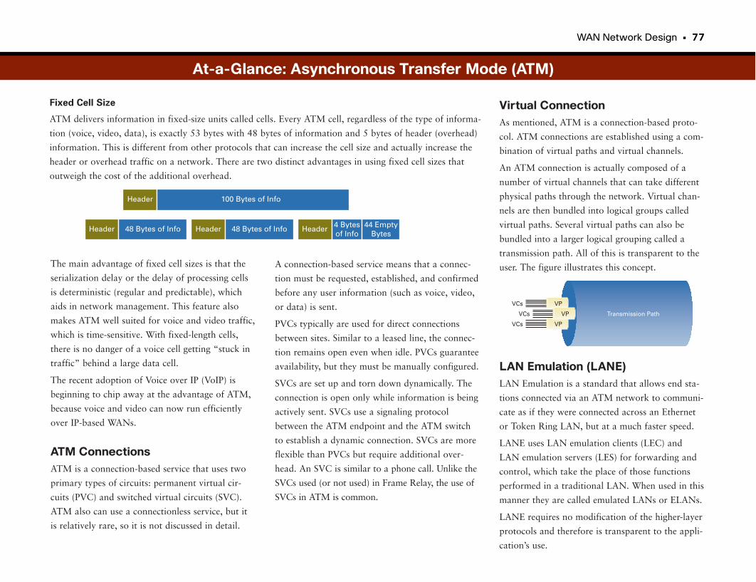
WAN Network Design • 77
Fixed Cell Size
ATM delivers information in fixed-size units called cells. Every ATM cell, regardless of the type of informa-
tion (voice, video, data), is exactly 53 bytes with 48 bytes of information and 5 bytes of header (overhead)
information. This is different from other protocols that can increase the cell size and actually increase the
header or overhead traffic on a network. There are two distinct advantages in using fixed cell sizes that
outweigh the cost of the additional overhead.
Virtual ConnectionAs mentioned, ATM is a connection-based proto-
col. ATM connections are established using a com-
bination of virtual paths and virtual channels.
An ATM connection is actually composed of a
number of virtual channels that can take different
physical paths through the network. Virtual chan-
nels are then bundled into logical groups called
virtual paths. Several virtual paths can also be
bundled into a larger logical grouping called a
transmission path. All of this is transparent to the
user. The figure illustrates this concept.
LAN Emulation (LANE)LAN Emulation is a standard that allows end sta-
tions connected via an ATM network to communi-
cate as if they were connected across an Ethernet
or Token Ring LAN, but at a much faster speed.
LANE uses LAN emulation clients (LEC) and
LAN emulation servers (LES) for forwarding and
control, which take the place of those functions
performed in a traditional LAN. When used in this
manner they are called emulated LANs or ELANs.
LANE requires no modification of the higher-layer
protocols and therefore is transparent to the appli-
cation’s use.
The main advantage of fixed cell sizes is that the
serialization delay or the delay of processing cells
is deterministic (regular and predictable), which
aids in network management. This feature also
makes ATM well suited for voice and video traffic,
which is time-sensitive. With fixed-length cells,
there is no danger of a voice cell getting “stuck in
traffic” behind a large data cell.
The recent adoption of Voice over IP (VoIP) is
beginning to chip away at the advantage of ATM,
because voice and video can now run efficiently
over IP-based WANs.
ATM ConnectionsATM is a connection-based service that uses two
primary types of circuits: permanent virtual cir-
cuits (PVC) and switched virtual circuits (SVC).
ATM also can use a connectionless service, but it
is relatively rare, so it is not discussed in detail.
VPVCs
VPVCs
VPVCs Transmission Path
At-a-Glance: Asynchronous Transfer Mode (ATM)
Header 100 Bytes of Info
Header 48 Bytes of Info Header 48 Bytes of Info Header 4 Bytesof Info
44 EmptyBytes
A connection-based service means that a connec-
tion must be requested, established, and confirmed
before any user information (such as voice, video,
or data) is sent.
PVCs typically are used for direct connections
between sites. Similar to a leased line, the connec-
tion remains open even when idle. PVCs guarantee
availability, but they must be manually configured.
SVCs are set up and torn down dynamically. The
connection is open only while information is being
actively sent. SVCs use a signaling protocol
between the ATM endpoint and the ATM switch
to establish a dynamic connection. SVCs are more
flexible than PVCs but require additional over-
head. An SVC is similar to a phone call. Unlike the
SVCs used (or not used) in Frame Relay, the use of
SVCs in ATM is common.
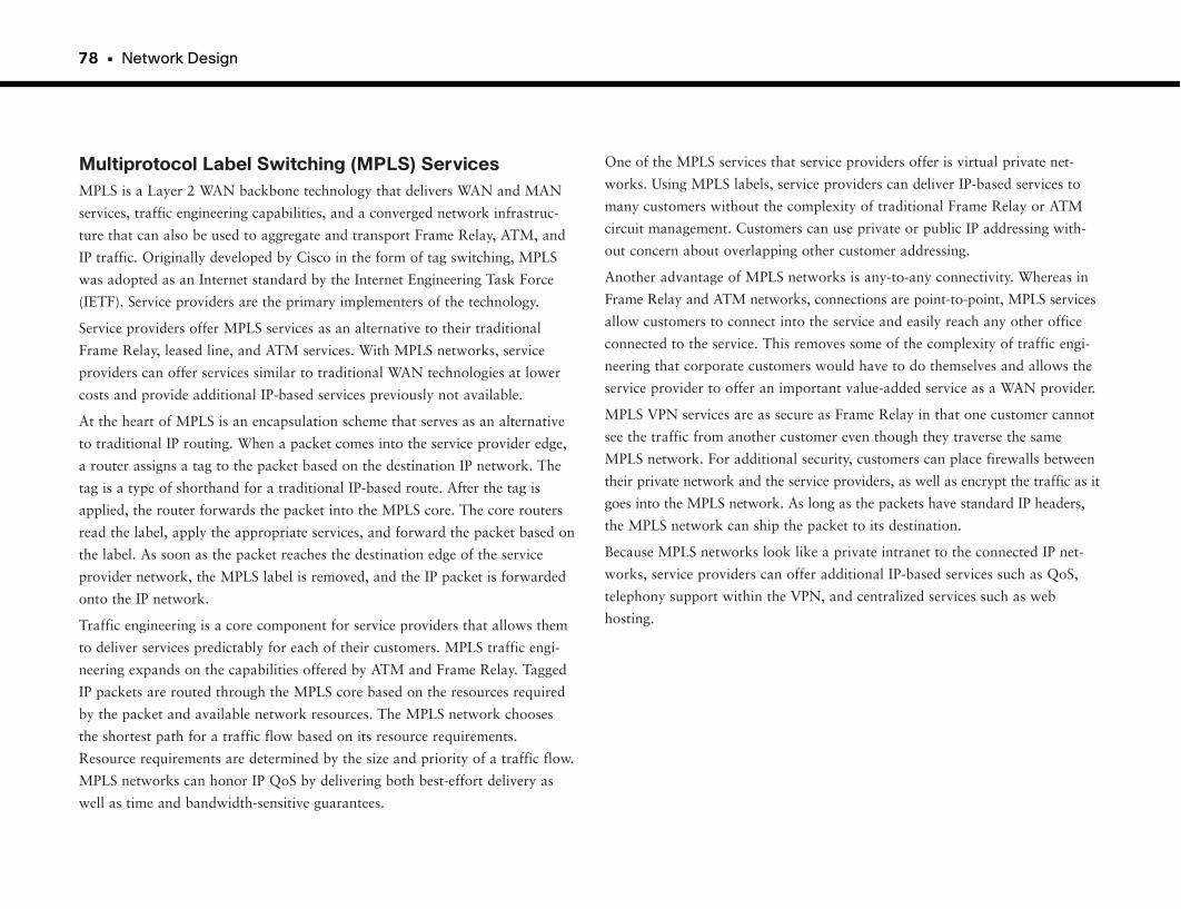
78 • Network Design
Multiprotocol Label Switching (MPLS) ServicesMPLS is a Layer 2 WAN backbone technology that delivers WAN and MAN
services, traffic engineering capabilities, and a converged network infrastruc-
ture that can also be used to aggregate and transport Frame Relay, ATM, and
IP traffic. Originally developed by Cisco in the form of tag switching, MPLS
was adopted as an Internet standard by the Internet Engineering Task Force
(IETF). Service providers are the primary implementers of the technology.
Service providers offer MPLS services as an alternative to their traditional
Frame Relay, leased line, and ATM services. With MPLS networks, service
providers can offer services similar to traditional WAN technologies at lower
costs and provide additional IP-based services previously not available.
At the heart of MPLS is an encapsulation scheme that serves as an alternative
to traditional IP routing. When a packet comes into the service provider edge,
a router assigns a tag to the packet based on the destination IP network. The
tag is a type of shorthand for a traditional IP-based route. After the tag is
applied, the router forwards the packet into the MPLS core. The core routers
read the label, apply the appropriate services, and forward the packet based on
the label. As soon as the packet reaches the destination edge of the service
provider network, the MPLS label is removed, and the IP packet is forwarded
onto the IP network.
Traffic engineering is a core component for service providers that allows them
to deliver services predictably for each of their customers. MPLS traffic engi-
neering expands on the capabilities offered by ATM and Frame Relay. Tagged
IP packets are routed through the MPLS core based on the resources required
by the packet and available network resources. The MPLS network chooses
the shortest path for a traffic flow based on its resource requirements.
Resource requirements are determined by the size and priority of a traffic flow.
MPLS networks can honor IP QoS by delivering both best-effort delivery as
well as time and bandwidth-sensitive guarantees.
One of the MPLS services that service providers offer is virtual private net-
works. Using MPLS labels, service providers can deliver IP-based services to
many customers without the complexity of traditional Frame Relay or ATM
circuit management. Customers can use private or public IP addressing with-
out concern about overlapping other customer addressing.
Another advantage of MPLS networks is any-to-any connectivity. Whereas in
Frame Relay and ATM networks, connections are point-to-point, MPLS services
allow customers to connect into the service and easily reach any other office
connected to the service. This removes some of the complexity of traffic engi-
neering that corporate customers would have to do themselves and allows the
service provider to offer an important value-added service as a WAN provider.
MPLS VPN services are as secure as Frame Relay in that one customer cannot
see the traffic from another customer even though they traverse the same
MPLS network. For additional security, customers can place firewalls between
their private network and the service providers, as well as encrypt the traffic as it
goes into the MPLS network. As long as the packets have standard IP headers,
the MPLS network can ship the packet to its destination.
Because MPLS networks look like a private intranet to the connected IP net-
works, service providers can offer additional IP-based services such as QoS,
telephony support within the VPN, and centralized services such as web
hosting.
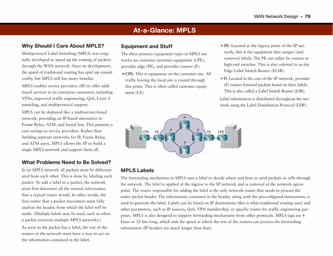
WAN Network Design • 79
Why Should I Care About MPLS?Multiprotocol Label Switching (MPLS) was origi-
nally developed to speed up the routing of packets
through the WAN network. Since its development,
the speed of traditional routing has sped up consid-
erably, but MPLS still has many benefits.
MPLS enables service providers (SP) to offer addi-
tional services to its enterprise customers, including
VPNs, improved traffic engineering, QoS, Layer 2
tunneling, and multiprotocol support.
MPLS can be deployed like a multiservice-based
network, providing an IP-based alternative to
Frame Relay, ATM, and leased line. This presents a
cost savings to service providers. Rather than
building separate networks for IP, Frame Relay,
and ATM users, MPLS allows the SP to build a
single MPLS network and support them all.
What Problems Need to Be Solved?In an MPLS network all packets must be differenti-
ated from each other. This is done by labeling each
packet. To add a label to a packet, the network
must first determine all the normal information
that a typical router would. In other words, the
first router that a packet encounters must fully
analyze the header, from which the label will be
made. (Multiple labels may be used, such as when
a packet traverses multiple MPLS networks.)
As soon as the packet has a label, the rest of the
routers in the network must have a way to act on
the information contained in the label.
• PE: Located at the ingress point of the SP net-
work, this is the equipment that assigns (and
removes) labels. The PE can either be routers or
high-end switches. This is also referred to as the
Edge Label Switch Router (ELSR).
• P: Located in the core of the SP network, provider
(P) routers forward packets based on their labels.
This is also called a Label Switch Router (LSR).
Label information is distributed throughout the net-
work using the Label Distribution Protocol (LDP).
Equipment and StuffThe three primary equipment types in MPLS net-
works are customer premises equipment (CPE),
provider edge (PE), and provider routers (P):
• CPE: This is equipment on the customer site. All
traffic leaving the local site is routed through
this point. This is often called customer equip-
ment (CE).
At-a-Glance: MPLS
CPE CPEPE PEP P
P
P
MPLS LabelsThe forwarding mechanism in MPLS uses a label to decide where and how to send packets or cells through
the network. The label is applied at the ingress to the SP network and is removed at the network egress
point. The router responsible for adding the label is the only network router that needs to process the
entire packet header. The information contained in the header, along with the preconfigured instructions, is
used to generate the label. Labels can be based on IP destinations (this is what traditional routing uses) and
other parameters, such as IP sources, QoS, VPN membership, or specific routes for traffic engineering pur-
poses. MPLS is also designed to support forwarding mechanisms from other protocols. MPLS tags are 4
bytes or 32 bits long, which aids the speed at which the rest of the routers can process the forwarding
information (IP headers are much longer than that).
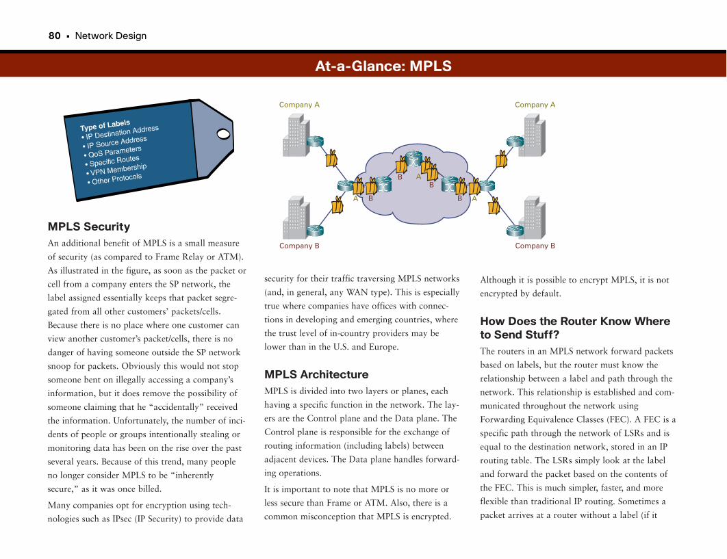
80 • Network Design
MPLS SecurityAn additional benefit of MPLS is a small measure
of security (as compared to Frame Relay or ATM).
As illustrated in the figure, as soon as the packet or
cell from a company enters the SP network, the
label assigned essentially keeps that packet segre-
gated from all other customers’ packets/cells.
Because there is no place where one customer can
view another customer’s packet/cells, there is no
danger of having someone outside the SP network
snoop for packets. Obviously this would not stop
someone bent on illegally accessing a company’s
information, but it does remove the possibility of
someone claiming that he “accidentally” received
the information. Unfortunately, the number of inci-
dents of people or groups intentionally stealing or
monitoring data has been on the rise over the past
several years. Because of this trend, many people
no longer consider MPLS to be “inherently
secure,” as it was once billed.
Many companies opt for encryption using tech-
nologies such as IPsec (IP Security) to provide data
Although it is possible to encrypt MPLS, it is not
encrypted by default.
How Does the Router Know Whereto Send Stuff?The routers in an MPLS network forward packets
based on labels, but the router must know the
relationship between a label and path through the
network. This relationship is established and com-
municated throughout the network using
Forwarding Equivalence Classes (FEC). A FEC is a
specific path through the network of LSRs and is
equal to the destination network, stored in an IP
routing table. The LSRs simply look at the label
and forward the packet based on the contents of
the FEC. This is much simpler, faster, and more
flexible than traditional IP routing. Sometimes a
packet arrives at a router without a label (if it
security for their traffic traversing MPLS networks
(and, in general, any WAN type). This is especially
true where companies have offices with connec-
tions in developing and emerging countries, where
the trust level of in-country providers may be
lower than in the U.S. and Europe.
MPLS ArchitectureMPLS is divided into two layers or planes, each
having a specific function in the network. The lay-
ers are the Control plane and the Data plane. The
Control plane is responsible for the exchange of
routing information (including labels) between
adjacent devices. The Data plane handles forward-
ing operations.
It is important to note that MPLS is no more or
less secure than Frame or ATM. Also, there is a
common misconception that MPLS is encrypted.
At-a-Glance: MPLS
Type of Labels
• IP Destination Address
• IP Source Address
• QoS Parameters
• Specific Routes
• VPN Membership
• Other Protocols
Company A
Company B
Company A
A
A
A
Company B
B
BB
B

came from a non-MPLS network). When this hap-
pens, it is the router’s job to add a label so that the
packet can be properly forwarded through the
MPLS network.
Other MPLS FeaturesTraffic engineering is the ability to dynamically
define routes based on known demand or alterna-
tive available routes. Traffic engineering can also
be used to optimize network usage.
Intelligent rerouting refers to an MPLS network’s
ability to reroute based on network congestion.
Rather than changing the route on a packet-by-
packet basis, MPLS can reroute on a flow-by-flow
basis.
MPLS is particularly well suited to support VPNs.
With a VPN, the packets from one enterprise are
transparent to all other enterprise VPNs. The labels
and the FECs effectively segregate VPN traffic
from other packets on the MPLS network.
MPLS Layer 2 tunneling, also known as Any
Transport over MPLS (AToM), allows an SP to
transport Frame Relay and ATM over an MPLS-
based network. This increases the range of services
that the SP can offer.
At-a-Glance: MPLS
WAN Network Design • 81
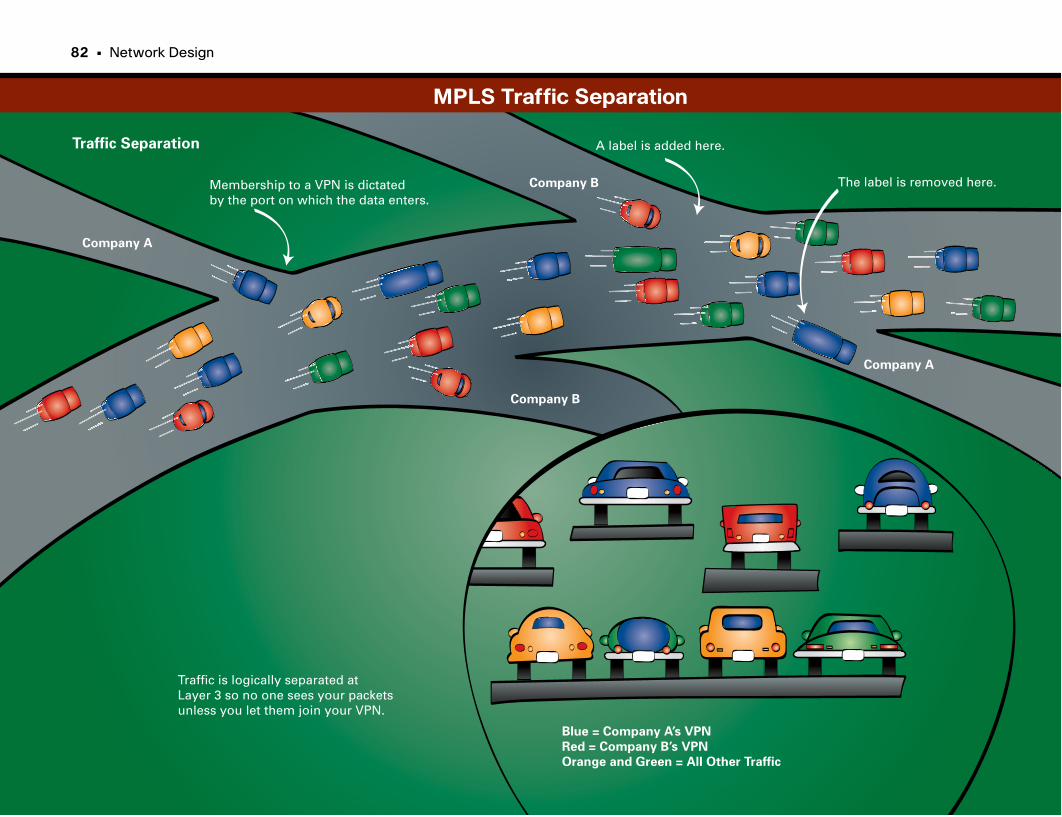
The label is removed here.
A label is added here.Traffic Separation
Company A
Company A
Company B
Company BMembership to a VPN is dictated by the port on which the data enters.
Traffic is logically separated atLayer 3 so no one sees your packetsunless you let them join your VPN.
Blue = Company A’s VPN
Red = Company B’s VPN
Orange and Green = All Other Traffic
82 • Network Design
MPLS Traffic Separation

This page intentionally left blank

Broadband Technologies
Always-on AccessBefore the late 1990s, people connected remotely to their offices or the
Internet using dialup connections. An always-on remote network connection
was not possible for a reasonable price. To connect to the corporate network,
the user ran a program that dialed a phone number. Unless the user had a sec-
ond phone line, being online prohibited incoming or outgoing phone calls.
The user entered a user ID and password to gain access to the system. The
fastest speed available over phone lines was 56 kbps, which was fine until the
web became popular in the 1990s. Downloading large pictures, documents,
applications, and audio files took what seemed like forever. Then, along came
broadband.
Broadband networking offered a reasonable high-speed alternative to tradi-
tional dialup networking. Using existing service connections to houses (such as
phone wiring, cable TV coaxial cable, or even satellite), service providers
offered Internet services at many times the speed of dialup. Downloading large
files became palatable with broadband. Broadband technologies allow service
providers to offer always-on connectivity similar to what people use in a cor-
porate network. Computers on the broadband network always have access to
the network; there is no intermediate dialup step. Sit down, load the browser,
and off you go.
High-speed Internet access to homes offers new levels of productivity and
entertainment not possible before the commercialization of the Internet and
the web. Aside from apparent uses such as online shopping and video stream-
ing, corporations can accommodate road warriors and work-from-home folks
in a way not previously possible. Using encryption technologies, an employee
with a laptop computer can securely access her corporate network from any
Internet access point in the world. Additionally, employees can attach IP
phones, allowing them to work on their computers and make calls from their
office-phone extensions as if they were sitting at their desks.
Broadband Technology EvolutionIntegrated Services Digital Network (ISDN) was the first commercially viable
broadband option available. Using existing phone lines, home users commonly
subscribed to a Basic Rate Interface (BRI), which had a throughput maximum
of 128 kbps. ISDN had some significant adoption in Europe, but in the U.S.,
ISDN was eclipsed by more cost-effective broadband technologies before it
had a chance to become commonplace. Cable modem and digital subscriber
line (DSL) services became the premier broadband technologies. Although
other broadband technologies existed, the primary determination of a technol-
ogy’s viability was access to “last mile” wiring to houses. Anything that
required new wiring probably wouldn’t make it. Other technologies that take
advantage of other media exist, such as satellite television dishes, but they did
not become widely adopted.
For those requiring even higher throughput, some providers now offer fiber
links to homes as a premier service. This is already popular throughout major
cities in Asia and is being installed in several cities in the U.S. as well.
Cable Modem
Cable modems provide high-speed data communication using existing cable
television coaxial cabling. Current implementations of cable-modem technolo-
gies offer speeds as fast as Ethernet (greater than 10 Mbps). This means that a
file that takes 2 minutes to transfer over ISDN takes 2 seconds over a cable
modem. Cable modem can provide higher speeds than traditional leased lines,
with lower cost and easier installation. Because a cable-modem connection is
permanently established, it cannot dial multiple locations directly. As a result,
cable-modem access must be to the Internet. This restriction means that
employees can connect to their company’s network only if the company pro-
vides access through the Internet. Usually, this is done through a secure VPN
connection.
DSL
Like cable modems, DSL provides high-speed Internet access for reasonable
cost using existing cabling to houses and businesses. DSL carves off a portion
of the telephone line to use for data transmission without interfering with
existing phone service. Because of the multiple flavors of DSL services, DSL
is generically referred to as xDSL. The two popular forms of xDSL service
86 • Network Design
currently available are Asymmetric DSL (ADSL) and Symmetric DSL (SDSL).
ADSL provides faster download speeds because traffic toward the user is given
more bandwidth than traffic from the user. SDSL assigns equal bandwidth in
both directions. ADSL is most often used for residential service, and SDSL is
most often used in commercial settings, because of their different usage models.
Which One Is Better?
Both DSL and cable modems provide high-speed Internet access at a relatively
low cost. Both provide always-on connectivity. Both have technical advantages
and disadvantages. Either technology makes a good to-the-home or small-
office solution for Internet connectivity. Because both technologies are always
on, a firewall must protect the local network from Internet-based attacks.
Some practical issues affect how widespread the technologies become.
Virtually all businesses and homes have telephone lines, which means that DSL
is possible, but fewer homes and businesses have cable TV connections. In gen-
eral, neither is “better,” and both types of service offer very high-speed con-
nectivity for relatively low cost.
In some cases, though, there may not be a choice if you live in an area not
serviced by cable, for example. When both services exist, the quality and price
may be the tipping point between the two services. A great deal of information
on setting up cable and DSL networks can be found in Home Networking
Simplified (Cisco Press, 2006).
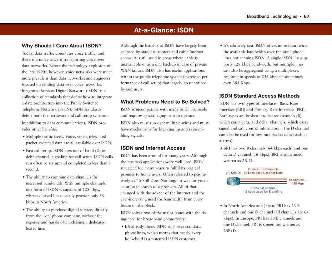
Broadband Technologies • 87
Why Should I Care About ISDN?Today, data traffic dominates voice traffic, and
there is a move toward transporting voice over
data networks. Before the technology explosion of
the late 1990s, however, voice networks were much
more prevalent than data networks, and engineers
focused on sending data over voice networks.
Integrated Services Digital Network (ISDN) is a
collection of standards that define how to integrate
a data architecture into the Public Switched
Telephone Network (PSTN). ISDN standards
define both the hardware and call setup schemes.
In addition to data communications, ISDN pro-
vides other benefits:
• Multiple traffic feeds. Voice, video, telex, and
packet-switched data are all available over ISDN.
• Fast call setup. ISDN uses out-of-band (D, or
delta channel) signaling for call setup. ISDN calls
can often be set up and completed in less than 1
second.
• The ability to combine data channels for
increased bandwidth. With multiple channels,
one form of ISDN is capable of 128 kbps,
whereas leased lines usually provide only 56
kbps in North America.
• The ability to purchase digital services directly
from the local phone company, without the
expense and hassle of purchasing a dedicated
leased line.
• It’s relatively fast. ISDN offers more than twice
the available bandwidth over the same phone
lines not running ISDN. A single ISDN line sup-
ports 128 kbps bandwidth, but multiple lines
can also be aggregated using a multiplexer,
resulting in speeds of 256 kbps or sometimes
even 384 Kbps.
ISDN Standard Access MethodsISDN has two types of interfaces: Basic Rate
Interface (BRI) and Primary Rate Interface (PRI).
Both types are broken into bearer channels (B),
which carry data, and delta channels, which carry
signal and call control information. The D channel
can also be used for low-rate packet data (such as
alarms).
• BRI has two B channels (64 kbps each) and one
delta D channel (16 kbps). BRI is sometimes
written as 2B+D.
• In North America and Japan, PRI has 23 B
channels and one D channel (all channels are 64
kbps). In Europe, PRI has 30 B channels and
one D channel. PRI is sometimes written as
23B+D.
Although the benefits of ISDN have largely been
eclipsed by standard routers and cable Internet
access, it is still used in areas where cable is
unavailable or as a dial backup in case of private
WAN failure. ISDN also has useful applications
within the public telephone system (increased per-
formance of call setup) that largely go unnoticed
by end users.
What Problems Need to Be Solved?ISDN is incompatible with many other protocols
and requires special equipment to operate.
ISDN also must run over multiple wires and must
have mechanisms for breaking up and reassem-
bling signals.
ISDN and Internet AccessISDN has been around for many years. Although
the business applications were well used, ISDN
struggled for many years to fulfill its original
promise to home users. Often referred to pejora-
tively as “It Still Does Nothing,” it was for year a
solution in search of a problem. All of that
changed with the advent of the Internet and the
ever-increasing need for bandwidth from every
house on the block.
ISDN solves two of the major issues with the ris-
ing need for broadband connectivity:
• It’s already there. ISDN runs over standard
phone lines, which means that nearly every
household is a potential ISDN customer.
2 Bearer (B) Channels64 kbps Each Used for Data
1 Data (D) Channel16 kbps Used for Signaling
BRI (2B+D)
Bandwidth = 128 kbps
At-a-Glance: ISDN
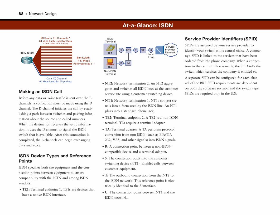
88 • Network Design
• NT2: Network termination 2. An NT2 aggre-
gates and switches all ISDN lines at the customer
service site using a customer switching device.
• NT1: Network termination 1. NT1s convert sig-
nals into a form used by the ISDN line. An NT1
plugs into a standard phone jack.
• TE2: Terminal endpoint 2. A TE2 is a non-ISDN
terminal. TEs require a terminal adapter.
• TA: Terminal adapter. A TA performs protocol
conversion from non-ISDN (such as EIA/TIA-
232, V.35, and other signals) into ISDN signals.
• R: A connection point between a non-ISDN-
compatible device and a terminal adapter.
• S: The connection point into the customer
switching device (NT2). Enables calls between
customer equipment.
• T: The outbound connection from the NT2 to
the ISDN network. This reference point is elec-
trically identical to the S interface.
• U: The connection point between NT1 and the
ISDN network.
Service Provider Identifiers (SPID)SPIDs are assigned by your service provider to
identify your switch at the central office. A compa-
ny’s SPID is linked to the services that have been
ordered from the phone company. When a connec-
tion to the central office is made, the SPID tells the
switch which services the company is entitled to.
A separate SPID can be configured for each chan-
nel of the BRI. SPID requirements are dependent
on both the software revision and the switch type.
SPIDs are required only in the U.S.Making an ISDN CallBefore any data or voice traffic is sent over the B
channels, a connection must be made using the D
channel. The D channel initiates the call by estab-
lishing a path between switches and passing infor-
mation about the source and called numbers.
When the destination receives the setup informa-
tion, it uses the D channel to signal the ISDN
switch that is available. After this connection is
completed, the B channels can begin exchanging
data and voice.
ISDN Device Types and ReferencePointsISDN specifies both the equipment and the con-
nection points between equipment to ensure
compatibility with the PSTN and among ISDN
vendors.
• TE1: Terminal endpoint 1. TE1s are devices that
have a native ISDN interface.
At-a-Glance: ISDN
23 Bearer (B) Channels *64 kbps Each Used for Data
* (30 B Channels in Europe)
1 Data (D) Channel64 kbps Used for Signaling
PRI (23B+D)
Bandwidth1.47 Mbps
(Referred to as T1)
ServiceProviderNetwork
S
R
UTNT2 NT1
TA
TE1
ISDNTerminal
LocalLoop
Non-ISDNTerminal
TE2
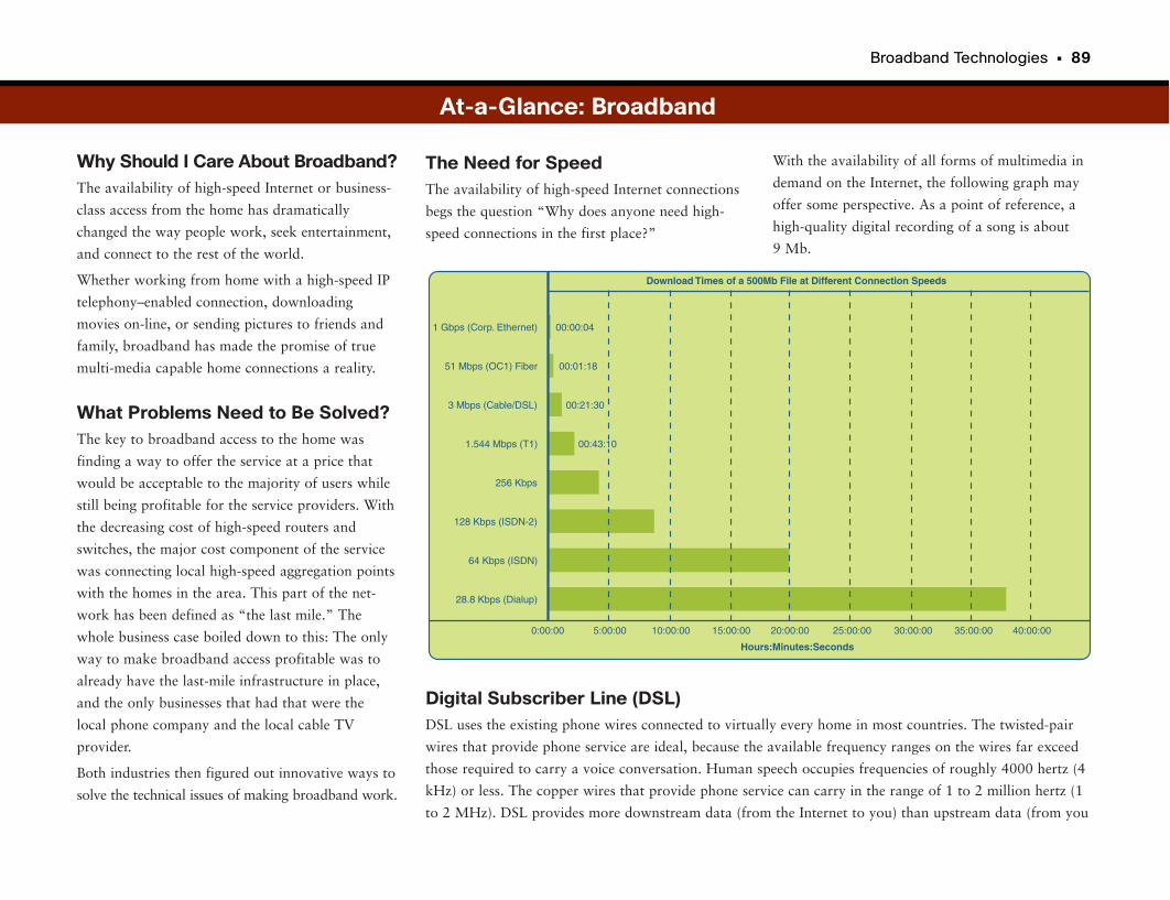
Broadband Technologies • 89
Why Should I Care About Broadband?The availability of high-speed Internet or business-
class access from the home has dramatically
changed the way people work, seek entertainment,
and connect to the rest of the world.
Whether working from home with a high-speed IP
telephony–enabled connection, downloading
movies on-line, or sending pictures to friends and
family, broadband has made the promise of true
multi-media capable home connections a reality.
What Problems Need to Be Solved?The key to broadband access to the home was
finding a way to offer the service at a price that
would be acceptable to the majority of users while
still being profitable for the service providers. With
the decreasing cost of high-speed routers and
switches, the major cost component of the service
was connecting local high-speed aggregation points
with the homes in the area. This part of the net-
work has been defined as “the last mile.” The
whole business case boiled down to this: The only
way to make broadband access profitable was to
already have the last-mile infrastructure in place,
and the only businesses that had that were the
local phone company and the local cable TV
provider.
Both industries then figured out innovative ways to
solve the technical issues of making broadband work.
With the availability of all forms of multimedia in
demand on the Internet, the following graph may
offer some perspective. As a point of reference, a
high-quality digital recording of a song is about
9 Mb.
The Need for SpeedThe availability of high-speed Internet connections
begs the question “Why does anyone need high-
speed connections in the first place?”
1 Gbps (Corp. Ethernet)
51 Mbps (OC1) Fiber
Hours:Minutes:Seconds
Download Times of a 500Mb File at Different Connection Speeds
3 Mbps (Cable/DSL)
1.544 Mbps (T1)
00:00:04
0:00:00 5:00:00 10:00:00 15:00:00 20:00:00 25:00:00 30:00:00 35:00:00
00:01:18
00:21:30
256 Kbps
128 Kbps (ISDN-2)
64 Kbps (ISDN)
28.8 Kbps (Dialup)
40:00:00
00:43:10
At-a-Glance: Broadband
Digital Subscriber Line (DSL)DSL uses the existing phone wires connected to virtually every home in most countries. The twisted-pair
wires that provide phone service are ideal, because the available frequency ranges on the wires far exceed
those required to carry a voice conversation. Human speech occupies frequencies of roughly 4000 hertz (4
kHz) or less. The copper wires that provide phone service can carry in the range of 1 to 2 million hertz (1
to 2 MHz). DSL provides more downstream data (from the Internet to you) than upstream data (from you
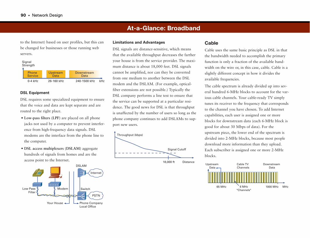
90 • Network Design
to the Internet) based on user profiles, but this can
be changed for businesses or those running web
servers.
DSL Equipment
DSL requires some specialized equipment to ensure
that the voice and data are kept separate and are
routed to the right place.
• Low-pass filters (LPF) are placed on all phone
jacks not used by a computer to prevent interfer-
ence from high-frequency data signals. DSL
modems are the interface from the phone line to
the computer.
• DSL access multiplexers (DSLAM) aggregate
hundreds of signals from homes and are the
access point to the Internet.
CableCable uses the same basic principle as DSL in that
the bandwidth needed to accomplish the primary
function is only a fraction of the available band-
width on the wire or, in this case, cable. Cable is a
slightly different concept in how it divides the
available frequencies.
The cable spectrum is already divided up into sev-
eral hundred 6-MHz blocks to account for the var-
ious cable channels. Your cable-ready TV simply
tunes its receiver to the frequency that corresponds
to the channel you have chosen. To add Internet
capabilities, each user is assigned one or more
blocks for downstream data (each 6-MHz block is
good for about 30 Mbps of data). For the
upstream piece, the lower end of the spectrum is
divided into 2-MHz blocks, because most people
download more information than they upload.
Each subscriber is assigned one or more 2-MHz
blocks.
Limitations and Advantages
DSL signals are distance-sensitive, which means
that the available throughput decreases the farther
your house is from the service provider. The maxi-
mum distance is about 18,000 feet. DSL signals
cannot be amplified, nor can they be converted
from one medium to another between the DSL
modem and the DSLAM. (For example, optical-
fiber extensions are not possible.) Typically the
DSL company performs a line test to ensure that
the service can be supported at a particular resi-
dence. The good news for DSL is that throughput
is unaffected by the number of users so long as the
phone company continues to add DSLAMs to sup-
port new users.
At-a-Glance: Broadband
0-4 kHz
PhoneService
UpstreamData
DownstreamData
26-160 kHz 240-1500 kHz
SignalStrength
kHz
Internet
Modem
DSLAM
Switch
Your House Phone CompanyLocal Office
Low PassFilter
PSTN
18,000 ft
Throughput (kbps)
Signal Cutoff
Distance
6 MHz"Channels"
DownstreamData
Cable TV Channels
UpstreamData
MHz1000 MHz65 MHz
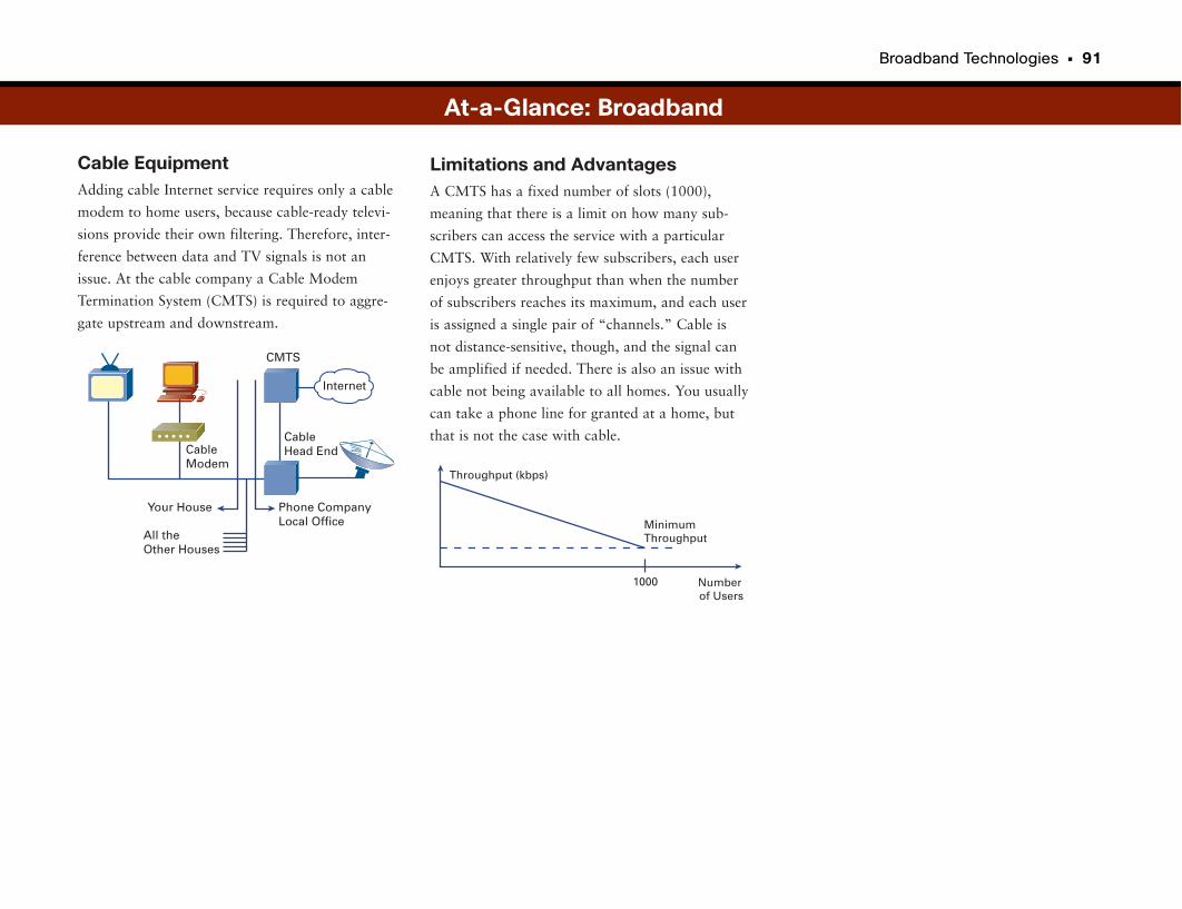
Broadband Technologies • 91
Cable EquipmentAdding cable Internet service requires only a cable
modem to home users, because cable-ready televi-
sions provide their own filtering. Therefore, inter-
ference between data and TV signals is not an
issue. At the cable company a Cable Modem
Termination System (CMTS) is required to aggre-
gate upstream and downstream.
Limitations and AdvantagesA CMTS has a fixed number of slots (1000),
meaning that there is a limit on how many sub-
scribers can access the service with a particular
CMTS. With relatively few subscribers, each user
enjoys greater throughput than when the number
of subscribers reaches its maximum, and each user
is assigned a single pair of “channels.” Cable is
not distance-sensitive, though, and the signal can
be amplified if needed. There is also an issue with
cable not being available to all homes. You usually
can take a phone line for granted at a home, but
that is not the case with cable.
Internet
CableModem
CMTS
CableHead End
Your House
All the Other Houses
Phone CompanyLocal Office
At-a-Glance: Broadband
1000
Throughput (kbps)
MinimumThroughput
Numberof Users
Virtual Private Networks
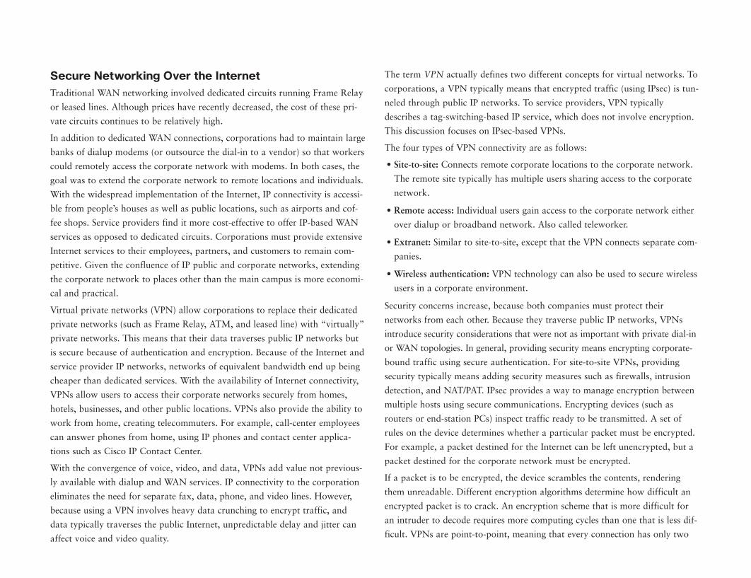
Secure Networking Over the InternetTraditional WAN networking involved dedicated circuits running Frame Relay
or leased lines. Although prices have recently decreased, the cost of these pri-
vate circuits continues to be relatively high.
In addition to dedicated WAN connections, corporations had to maintain large
banks of dialup modems (or outsource the dial-in to a vendor) so that workers
could remotely access the corporate network with modems. In both cases, the
goal was to extend the corporate network to remote locations and individuals.
With the widespread implementation of the Internet, IP connectivity is accessi-
ble from people’s houses as well as public locations, such as airports and cof-
fee shops. Service providers find it more cost-effective to offer IP-based WAN
services as opposed to dedicated circuits. Corporations must provide extensive
Internet services to their employees, partners, and customers to remain com-
petitive. Given the confluence of IP public and corporate networks, extending
the corporate network to places other than the main campus is more economi-
cal and practical.
Virtual private networks (VPN) allow corporations to replace their dedicated
private networks (such as Frame Relay, ATM, and leased line) with “virtually”
private networks. This means that their data traverses public IP networks but
is secure because of authentication and encryption. Because of the Internet and
service provider IP networks, networks of equivalent bandwidth end up being
cheaper than dedicated services. With the availability of Internet connectivity,
VPNs allow users to access their corporate networks securely from homes,
hotels, businesses, and other public locations. VPNs also provide the ability to
work from home, creating telecommuters. For example, call-center employees
can answer phones from home, using IP phones and contact center applica-
tions such as Cisco IP Contact Center.
With the convergence of voice, video, and data, VPNs add value not previous-
ly available with dialup and WAN services. IP connectivity to the corporation
eliminates the need for separate fax, data, phone, and video lines. However,
because using a VPN involves heavy data crunching to encrypt traffic, and
data typically traverses the public Internet, unpredictable delay and jitter can
affect voice and video quality.
The term VPN actually defines two different concepts for virtual networks. To
corporations, a VPN typically means that encrypted traffic (using IPsec) is tun-
neled through public IP networks. To service providers, VPN typically
describes a tag-switching-based IP service, which does not involve encryption.
This discussion focuses on IPsec-based VPNs.
The four types of VPN connectivity are as follows:
• Site-to-site: Connects remote corporate locations to the corporate network.
The remote site typically has multiple users sharing access to the corporate
network.
• Remote access: Individual users gain access to the corporate network either
over dialup or broadband network. Also called teleworker.
• Extranet: Similar to site-to-site, except that the VPN connects separate com-
panies.
• Wireless authentication: VPN technology can also be used to secure wireless
users in a corporate environment.
Security concerns increase, because both companies must protect their
networks from each other. Because they traverse public IP networks, VPNs
introduce security considerations that were not as important with private dial-in
or WAN topologies. In general, providing security means encrypting corporate-
bound traffic using secure authentication. For site-to-site VPNs, providing
security typically means adding security measures such as firewalls, intrusion
detection, and NAT/PAT. IPsec provides a way to manage encryption between
multiple hosts using secure communications. Encrypting devices (such as
routers or end-station PCs) inspect traffic ready to be transmitted. A set of
rules on the device determines whether a particular packet must be encrypted.
For example, a packet destined for the Internet can be left unencrypted, but a
packet destined for the corporate network must be encrypted.
If a packet is to be encrypted, the device scrambles the contents, rendering
them unreadable. Different encryption algorithms determine how difficult an
encrypted packet is to crack. An encryption scheme that is more difficult for
an intruder to decode requires more computing cycles than one that is less dif-
ficult. VPNs are point-to-point, meaning that every connection has only two
94 • Network Design
endpoints. A single device (such as a WAN aggregation router) can have multi-
ple remote sites, and users terminate their connections on the one box, but
there is still one connection (or tunnel) per pair.
For each encrypted tunnel, the two endpoints must first authenticate each
other and ensure that the other end is who it claims to be. In encryption terms,
this means that each endpoint must establish a security association (SA) with
the other. Essentially, this involves the trusted exchange of information
between the two hosts that allows each to verify the identity of the other. This
process is called Internet Key Exchange (IKE). After both sides determine that
the other side is who it claims and that they can trust each other, they can send
encrypted data across the VPN.
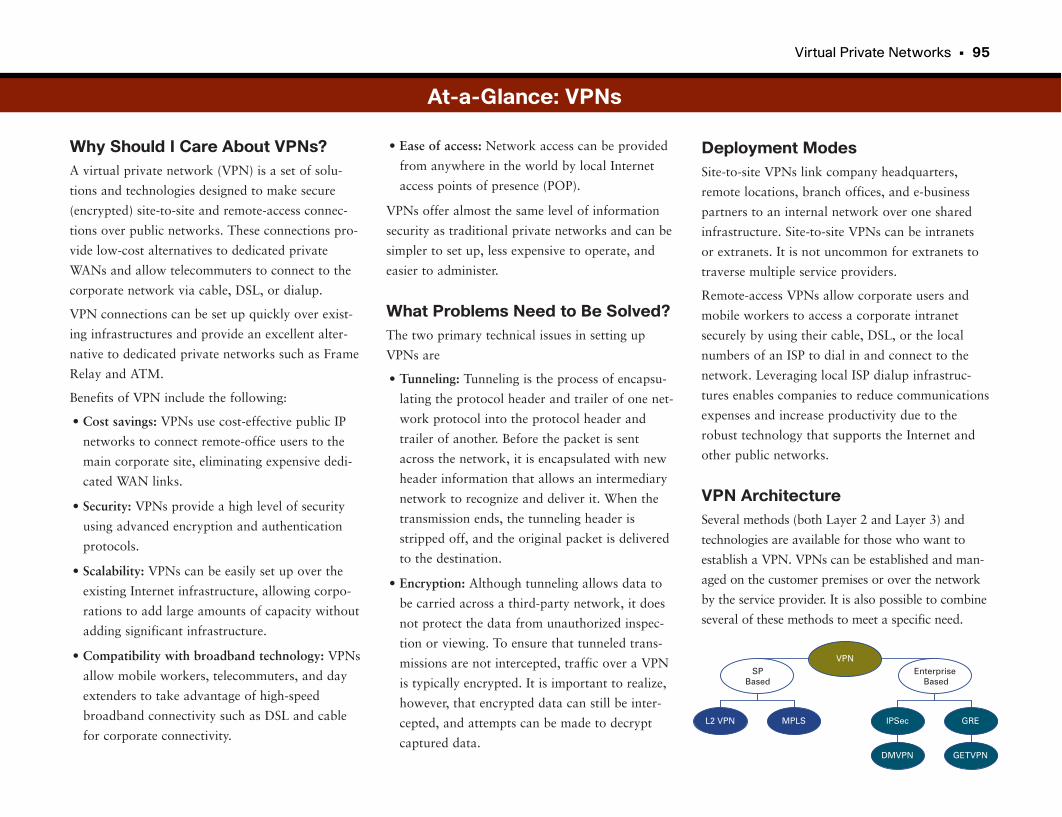
Virtual Private Networks • 95
Why Should I Care About VPNs?A virtual private network (VPN) is a set of solu-
tions and technologies designed to make secure
(encrypted) site-to-site and remote-access connec-
tions over public networks. These connections pro-
vide low-cost alternatives to dedicated private
WANs and allow telecommuters to connect to the
corporate network via cable, DSL, or dialup.
VPN connections can be set up quickly over exist-
ing infrastructures and provide an excellent alter-
native to dedicated private networks such as Frame
Relay and ATM.
Benefits of VPN include the following:
• Cost savings: VPNs use cost-effective public IP
networks to connect remote-office users to the
main corporate site, eliminating expensive dedi-
cated WAN links.
• Security: VPNs provide a high level of security
using advanced encryption and authentication
protocols.
• Scalability: VPNs can be easily set up over the
existing Internet infrastructure, allowing corpo-
rations to add large amounts of capacity without
adding significant infrastructure.
• Compatibility with broadband technology: VPNs
allow mobile workers, telecommuters, and day
extenders to take advantage of high-speed
broadband connectivity such as DSL and cable
for corporate connectivity.
Deployment ModesSite-to-site VPNs link company headquarters,
remote locations, branch offices, and e-business
partners to an internal network over one shared
infrastructure. Site-to-site VPNs can be intranets
or extranets. It is not uncommon for extranets to
traverse multiple service providers.
Remote-access VPNs allow corporate users and
mobile workers to access a corporate intranet
securely by using their cable, DSL, or the local
numbers of an ISP to dial in and connect to the
network. Leveraging local ISP dialup infrastruc-
tures enables companies to reduce communications
expenses and increase productivity due to the
robust technology that supports the Internet and
other public networks.
VPN ArchitectureSeveral methods (both Layer 2 and Layer 3) and
technologies are available for those who want to
establish a VPN. VPNs can be established and man-
aged on the customer premises or over the network
by the service provider. It is also possible to combine
several of these methods to meet a specific need.
• Ease of access: Network access can be provided
from anywhere in the world by local Internet
access points of presence (POP).
VPNs offer almost the same level of information
security as traditional private networks and can be
simpler to set up, less expensive to operate, and
easier to administer.
What Problems Need to Be Solved?The two primary technical issues in setting up
VPNs are
• Tunneling: Tunneling is the process of encapsu-
lating the protocol header and trailer of one net-
work protocol into the protocol header and
trailer of another. Before the packet is sent
across the network, it is encapsulated with new
header information that allows an intermediary
network to recognize and deliver it. When the
transmission ends, the tunneling header is
stripped off, and the original packet is delivered
to the destination.
• Encryption: Although tunneling allows data to
be carried across a third-party network, it does
not protect the data from unauthorized inspec-
tion or viewing. To ensure that tunneled trans-
missions are not intercepted, traffic over a VPN
is typically encrypted. It is important to realize,
however, that encrypted data can still be inter-
cepted, and attempts can be made to decrypt
captured data.
VPN
L2 VPN IPSec
EnterpriseBased
SPBased
MPLS GRE
DMVPN GETVPN
At-a-Glance: VPNs
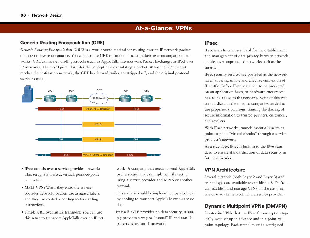
96 • Network Design
Generic Routing Encapsulation (GRE)Generic Routing Encapsulation (GRE) is a workaround method for routing over an IP network packets
that are otherwise unroutable. You can also use GRE to route multicast packets over incompatible net-
works. GRE can route non-IP protocols (such as AppleTalk, Internetwork Packet Exchange, or IPX) over
IP networks. The next figure illustrates the concept of encapsulating a packet. When the GRE packet
reaches the destination network, the GRE header and trailer are stripped off, and the original protocol
works as usual.
IPsecIPsec is an Internet standard for the establishment
and management of data privacy between network
entities over unprotected networks such as the
Internet.
IPsec security services are provided at the network
layer, allowing simple and effective encryption of
IP traffic. Before IPsec, data had to be encrypted
on an application basis, or hardware encryptors
had to be added to the network. None of this was
standardized at the time, so companies tended to
use proprietary solutions, limiting the sharing of
secure information to trusted partners, customers,
and resellers.
With IPsec networks, tunnels essentially serve as
point-to-point “virtual circuits” through a service
provider’s network.
As a side note, IPsec is built in to the IPv6 stan-
dard to ensure standardization of data security in
future networks.
VPN ArchitectureSeveral methods (both Layer 2 and Layer 3) and
technologies are available to establish a VPN. You
can establish and manage VPNs on the customer
site or over the network with a service provider.
Dynamic Multipoint VPNs (DMVPN)Site-to-site VPNs that use IPsec for encryption typ-
ically were set up in advance and in a point-to-
point topology. Each tunnel must be configured
• IPsec tunnels over a service provider network:
This setup is a trusted, virtual, point-to-point
connection.
• MPLS VPN: When they enter the service-
provider network, packets are assigned labels,
and they are routed according to forwarding
instructions.
• Simple GRE over an L2 transport: You can use
this setup to transport AppleTalk over an IP net-
At-a-Glance: VPNs
SP Network
CPE POP POPCORE
CPE
IPSecIPSec Standard L2 Transport
IPSec GREGRE IPSec
GREGRE MPLS
MPLS
MPLS or Other L2 Transport
work. A company that needs to send AppleTalk
over a secure link can implement this setup
using a service provider and MPLS or another
method.
This scenario could be implemented by a compa-
ny needing to transport AppleTalk over a secure
link.
By itself, GRE provides no data security; it sim-
ply provides a way to “tunnel” IP and non-IP
packets across an IP network.
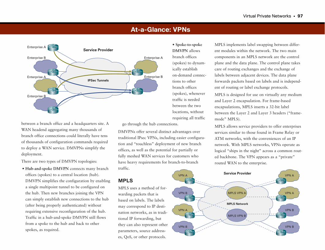
Virtual Private Networks • 97
between a branch office and a headquarters site. A
WAN headend aggregating many thousands of
branch office connections could literally have tens
of thousands of configuration commands required
to deploy a WAN service. DMVPNs simplify the
deployment.
There are two types of DMVPN topologies:
• Hub-and-spoke DMVPN connects many branch
offices (spokes) to a central location (hub).
DMVPN simplifies the configuration by enabling
a single multipoint tunnel to be configured on
the hub. Then new branches joining the VPN
can simply establish new connections to the hub
(after being properly authenticated) without
requiring extensive reconfiguration of the hub.
Traffic in a hub-and-spoke DMVPN still flows
from a spoke to the hub and back to other
spokes, as required.
MPLS implements label swapping between differ-
ent modules within the network. The two main
components in an MPLS network are the control
plane and the data plane. The control plane takes
care of routing exchanges and the exchange of
labels between adjacent devices. The data plane
forwards packets based on labels and is independ-
ent of routing or label exchange protocols.
MPLS is designed for use on virtually any medium
and Layer 2 encapsulation. For frame-based
encapsulations, MPLS inserts a 32-bit label
between the Layer 2 and Layer 3 headers (“frame-
mode” MPLS).
MPLS allows service providers to offer enterprises
services similar to those found in Frame Relay or
ATM networks, with the conveniences of an IP
network. With MPLS networks, VPNs operate as
logical “ships in the night” across a common rout-
ed backbone. The VPN appears as a “private”
routed WAN to the enterprise.
• Spoke-to-spoke
DMVPN allows
branch offices
(spokes) to dynam-
ically establish
on-demand connec-
tions to other
branch offices
(spokes), whenever
traffic is needed
between the two
locations, without
requiring all traffic
go through the hub connections.
DMVPNs offer several distinct advantages over
traditional IPsec VPNs, including easier configura-
tion and “touchless” deployment of new branch
offices, as well as the potential for partially or
fully meshed WAN services for customers who
have heavy requirements for branch-to-branch
traffic.
MPLSMPLS uses a method of for-
warding packets that is
based on labels. The labels
may correspond to IP desti-
nation networks, as in tradi-
tional IP forwarding, but
they can also represent other
parameters, source address-
es, QoS, or other protocols.
At-a-Glance: VPNs
Enterprise AService Provider
IPSec Tunnels
Enterprise B
Enterprise A
Enterprise B
Enterprise A
Enterprise B
VPN AService Provider
MPLS Network
VPN B
VPN A
VPN B
MPLS VPN A
MPLS VPN B
VPN A
VPN A
VPN B
VPN B
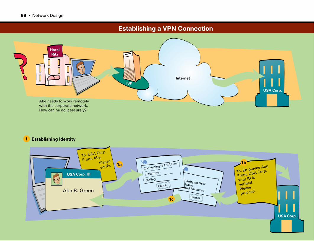
Cancel
Hotel
Ritz
USA Corp.
USA Corp.
Abe needs to work remotely with the corporate network.How can he do it securely?
ISP
Internet
1
1a 1b
1c
USA Corp. ID
Abe B. Green
Establishing Identity
To: USA Corp.
From: Abe
Please
verify.Connecting to USA Corp.
------------------------
----
Initializing
------------------------
----
Dialing
CancelVerifying User Name
and Password
To: Employee Abe
From: USA Corp.
Your ID is
verified.
Please
proceed.
Establishing a VPN Connection
98 • Network Design
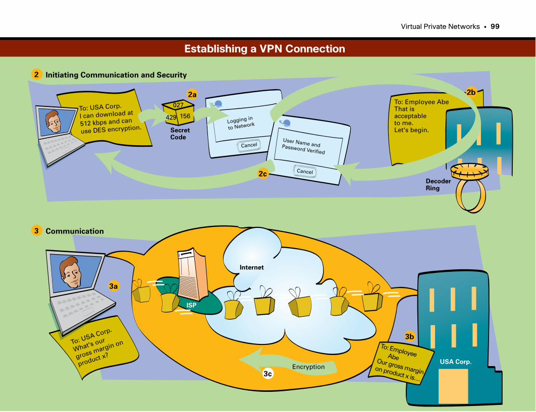
Virtual Private Networks • 99
USA Corp.
To: USA Corp.
I can download at
512 kbps and can
use DES encryption.
3
3a
3b
3c
Communication
2
2a 2b
2c
Initiating Communication and Security
To: USA Corp.
What's our
gross margin on
product x?
To: Employee AbeOur gross marginon product x is…
156
027
429
SecretCode
Logging in
to Network
Cancel
Cancel
User Name andPassword Verified
DecoderRing
To: Employee AbeThat isacceptableto me.Let's begin.
Internet
Encryption
ISP
Establishing a VPN Connection
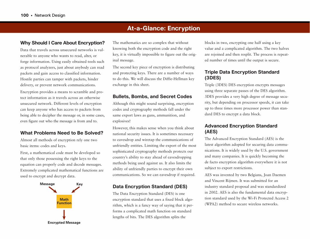
100 • Network Design
Why Should I Care About Encryption?Data that travels across unsecured networks is vul-
nerable to anyone who wants to read, alter, or
forge information. Using easily obtained tools such
as protocol analyzers, just about anybody can read
packets and gain access to classified information.
Hostile parties can tamper with packets, hinder
delivery, or prevent network communications.
Encryption provides a means to scramble and pro-
tect information as it travels across an otherwise
unsecured network. Different levels of encryption
can keep anyone who has access to packets from
being able to decipher the message or, in some cases,
even figure out who the message is from and to.
What Problems Need to Be Solved?Almost all methods of encryption rely one two
basic items: codes and keys.
First, a mathematical code must be developed so
that only those possessing the right keys to the
equation can properly code and decode messages.
Extremely complicated mathematical functions are
used to encrypt and decrypt data.
blocks in two, encrypting one half using a key
value and a complicated algorithm. The two halves
are rejoined and then resplit. The process is repeat-
ed number of times until the output is secure.
Triple Data Encryption Standard(3DES)Triple (3DES) DES encryption encrypts messages
using three separate passes of the DES algorithm.
3DES provides a very high degree of message secu-
rity, but depending on processor speeds, it can take
up to three times more processor power than stan-
dard DES to encrypt a data block.
Advanced Encryption Standard(AES)The Advanced Encryption Standard (AES) is the
latest algorithm adopted for securing data commu-
nications. It is widely used by the U.S. government
and many companies. It is quickly becoming the
de facto encryption algorithm everywhere it is not
subject to export restrictions.
AES was invented by two Belgians, Joan Daemen
and Vincent Rijmen. It was submitted for an
industry standard proposal and was standardized
in 2002. AES is also the fundamental data encryp-
tion standard used by the Wi-Fi Protected Access 2
(WPA2) method to secure wireless networks.
The mathematics are so complex that without
knowing both the encryption code and the right
key, it is virtually impossible to figure out the orig-
inal message.
The second key piece of encryption is distributing
and protecting keys. There are a number of ways
to do this. We will discuss the Diffie-Hellman key
exchange in this sheet.
Bullets, Bombs, and Secret CodesAlthough this might sound surprising, encryption
codes and cryptography methods fall under the
same export laws as guns, ammunition, and
explosives!
However, this makes sense when you think about
national security issues. It is sometimes necessary
to eavesdrop and wiretap the communications of
unfriendly entities. Limiting the export of the most
sophisticated cryptography methods protects our
country’s ability to stay ahead of eavesdropping
methods being used against us. It also limits the
ability of unfriendly parties to encrypt their own
communications. So we can eavesdrop if required.
Data Encryption Standard (DES)The Data Encryption Standard (DES) is one
encryption standard that uses a fixed block algo-
rithm, which is a fancy way of saying that it per-
forms a complicated math function on standard
lengths of bits. The DES algorithm splits the
At-a-Glance: Encryption
Message Key
Encrypted Message
MathFunction

Virtual Private Networks • 101
Using Keys to Encrypt StuffThe process of encrypting and decrypting data is
made possible through the use of keys. Without the
correct key, third parties are unable to unscramble
a coded message (however, any code can eventually
be cracked given enough computing power and
time). Some encryption methods use the concept of
a public key/private key pair to encode/decode
messages. A public key is mathematically derived
from the private key using a mathematical method
called factoring. A detailed explanation of factor-
ing is beyond the scope of this section, but the
important thing about factoring is that it makes it
nearly impossible to figure out a private key by
looking at the public key.
The result of an encryption is called a hash. Using
a private or session key, messages can be encoded.
Public keys are used to ensure that the message is
authentic and unchanged, and the private key is
used to decode the message.
very basic example of how this works. (Remember
in math class when you asked, “When will I ever
use this?” Well, here you go!)
N = prime number
G = a root of N
User 1 creates a very large random number A
User 2 creates a very large random number B
User 1 sends A to User 2
User 2 sends B to User 1
A = GA * (crazy math function using N)
B = GB * (crazy math function using N)
Both parties can now figure out the key (K) as
K = ([A]) B * (crazy math function using N)
K = ([B]) A * (crazy math function using N)
Diffie-Hellman Key ExchangeUnderstanding how encryption uses keys is only
half the battle. You must also have a secure way of
negotiating and passing keys without a third party
obtaining them, even when the keys are exchanged
over insecure links. The Diffie-Hellman key
exchange protocol was designed for just this pur-
pose. The exchange is secure because keys are
never transmitted in clear text, so they are excep-
tionally difficult to figure out. Key interception is
prevented using two known prime numbers that
have a special mathematical relationship to one
another, making it possible for two parties to agree
on a shared secret key. But it is impossible for
eavesdroppers to determine what this secret key is
(even if they know the shared primes). Here is a
At-a-Glance: Encryption
ΟυρΘυ αρτλψ Σαλεσ Λιαϕσβ Ηβαγσ Ιϕαη
SharedSecret Key
DES or 3DESAlgorithm
Encrypted Text
Clear Text
Our Quarterly Sales
Clear Text
Our Quarterly Sales
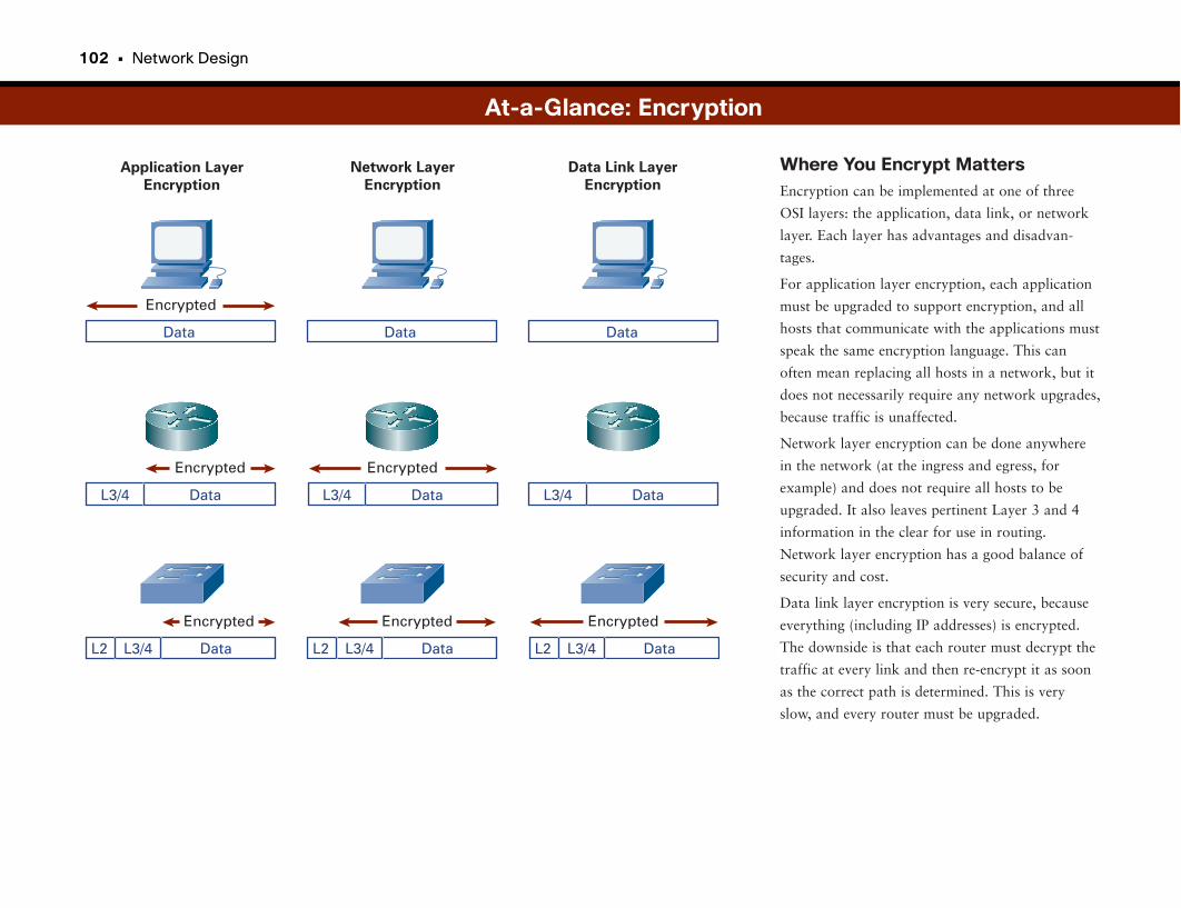
102 • Network Design
Where You Encrypt MattersEncryption can be implemented at one of three
OSI layers: the application, data link, or network
layer. Each layer has advantages and disadvan-
tages.
For application layer encryption, each application
must be upgraded to support encryption, and all
hosts that communicate with the applications must
speak the same encryption language. This can
often mean replacing all hosts in a network, but it
does not necessarily require any network upgrades,
because traffic is unaffected.
Network layer encryption can be done anywhere
in the network (at the ingress and egress, for
example) and does not require all hosts to be
upgraded. It also leaves pertinent Layer 3 and 4
information in the clear for use in routing.
Network layer encryption has a good balance of
security and cost.
Data link layer encryption is very secure, because
everything (including IP addresses) is encrypted.
The downside is that each router must decrypt the
traffic at every link and then re-encrypt it as soon
as the correct path is determined. This is very
slow, and every router must be upgraded.
At-a-Glance: Encryption
Data Link Layer
Encryption
Network Layer
Encryption
Application Layer
Encryption
Encrypted
Data Data Data
Encrypted
DataL3/4
Encrypted
DataL2 L3/4
Encrypted
DataL2 L3/4
Encrypted
DataL2 L3/4
Encrypted
DataL3/4 DataL3/4
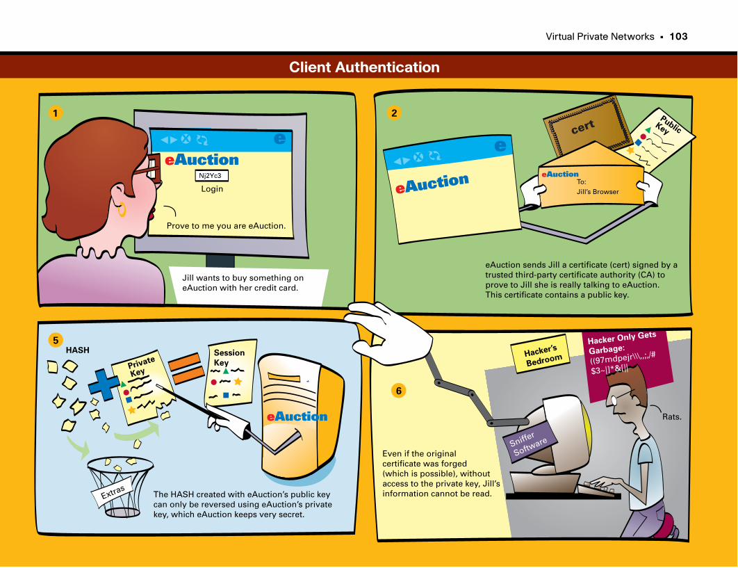
Virtual Private Networks • 103
X
X
eAuctioneAuction
eAuction
eAuction
Login
Jill wants to buy something oneAuction with her credit card.
Prove to me you are eAuction.
e e
eAuction sends Jill a certificate (cert) signed by atrusted third-party certificate authority (CA) to prove to Jill she is really talking to eAuction.This certificate contains a public key.
PublicKey
Nj2Yc3
HASH
The HASH created with eAuction’s public keycan only be reversed using eAuction’s privatekey, which eAuction keeps very secret.
Extras
1 2
5
6
To:
Jill’s Browser
Private
Key
Session
Key
Sniffer
Software
Hacker’s
Bedroom
Even if the originalcertificate was forged (which is possible), without access to the private key, Jill’s information cannot be read.
Hacker Only Gets
Garbage:
((97mdpejr\\\,,;,/#
$3~|]*&[||
Rats.
cert
Client Authentication
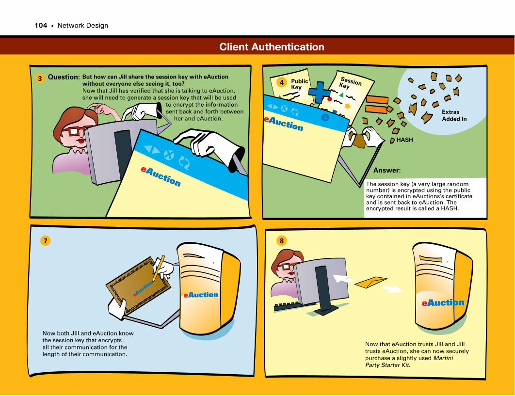
X
X
eAuction
34
7 8
eAuction
e
But how can Jill share the session key with eAuction
without everyone else seeing it, too?
Now that Jill has verified that she is talking to eAuction,she will need to generate a session key that will be used to encrypt the information sent back and forth between her and eAuction.
The session key (a very large randomnumber) is encrypted using the publickey contained in eAuctions’s certificate and is sent back to eAuction. The encrypted result is called a HASH.
Extras
Added In
Now that eAuction trusts Jill and Jill trusts eAuction, she can now securely purchase a slightly used MartiniParty Starter Kit.
PublicKey
SessionKey
Now both Jill and eAuction knowthe session key that encryptsall their communication for the length of their communication.
Question:
Answer:
HASH
eAuction
eAuctioneAuc
tion
Client Authentication
104 • Network Design

This page intentionally left blank
Optical Technologies
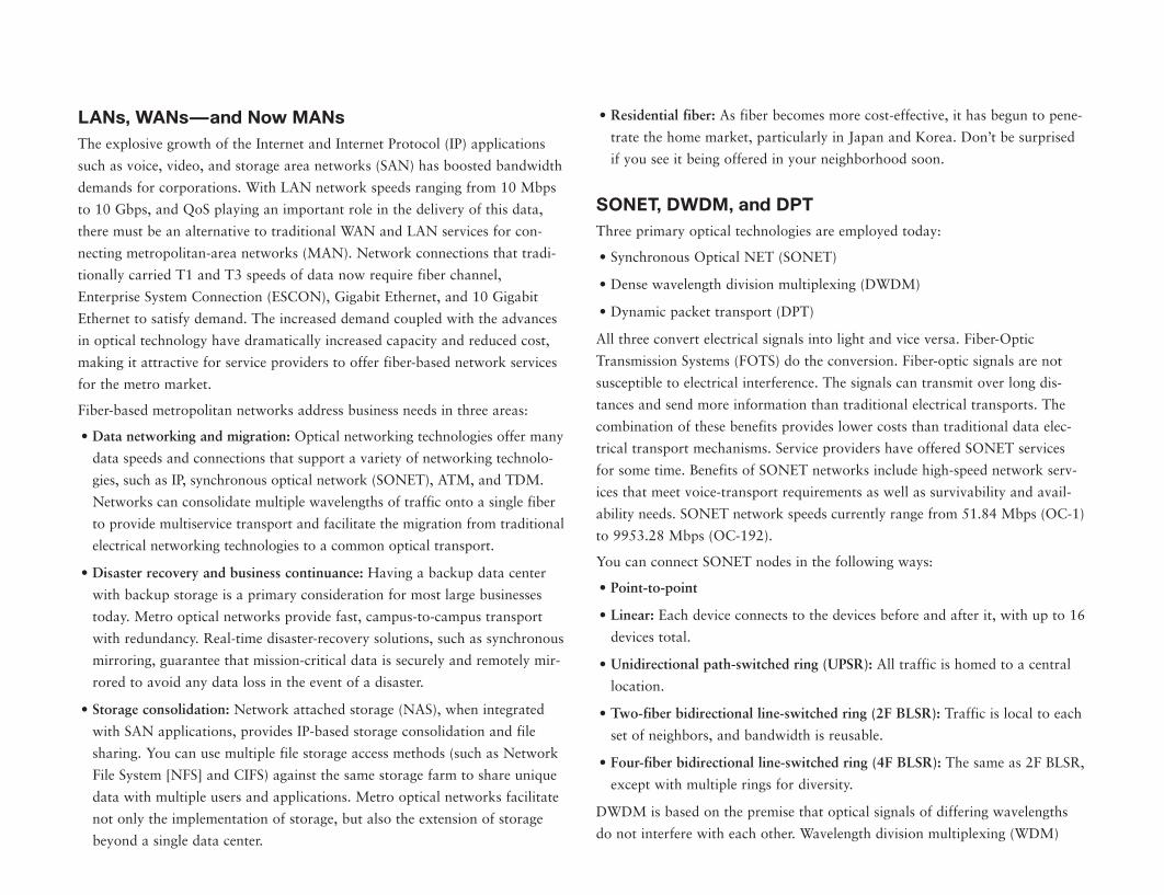
LANs, WANs—and Now MANsThe explosive growth of the Internet and Internet Protocol (IP) applications
such as voice, video, and storage area networks (SAN) has boosted bandwidth
demands for corporations. With LAN network speeds ranging from 10 Mbps
to 10 Gbps, and QoS playing an important role in the delivery of this data,
there must be an alternative to traditional WAN and LAN services for con-
necting metropolitan-area networks (MAN). Network connections that tradi-
tionally carried T1 and T3 speeds of data now require fiber channel,
Enterprise System Connection (ESCON), Gigabit Ethernet, and 10 Gigabit
Ethernet to satisfy demand. The increased demand coupled with the advances
in optical technology have dramatically increased capacity and reduced cost,
making it attractive for service providers to offer fiber-based network services
for the metro market.
Fiber-based metropolitan networks address business needs in three areas:
• Data networking and migration: Optical networking technologies offer many
data speeds and connections that support a variety of networking technolo-
gies, such as IP, synchronous optical network (SONET), ATM, and TDM.
Networks can consolidate multiple wavelengths of traffic onto a single fiber
to provide multiservice transport and facilitate the migration from traditional
electrical networking technologies to a common optical transport.
• Disaster recovery and business continuance: Having a backup data center
with backup storage is a primary consideration for most large businesses
today. Metro optical networks provide fast, campus-to-campus transport
with redundancy. Real-time disaster-recovery solutions, such as synchronous
mirroring, guarantee that mission-critical data is securely and remotely mir-
rored to avoid any data loss in the event of a disaster.
• Storage consolidation: Network attached storage (NAS), when integrated
with SAN applications, provides IP-based storage consolidation and file
sharing. You can use multiple file storage access methods (such as Network
File System [NFS] and CIFS) against the same storage farm to share unique
data with multiple users and applications. Metro optical networks facilitate
not only the implementation of storage, but also the extension of storage
beyond a single data center.
• Residential fiber: As fiber becomes more cost-effective, it has begun to pene-
trate the home market, particularly in Japan and Korea. Don’t be surprised
if you see it being offered in your neighborhood soon.
SONET, DWDM, and DPTThree primary optical technologies are employed today:
• Synchronous Optical NET (SONET)
• Dense wavelength division multiplexing (DWDM)
• Dynamic packet transport (DPT)
All three convert electrical signals into light and vice versa. Fiber-Optic
Transmission Systems (FOTS) do the conversion. Fiber-optic signals are not
susceptible to electrical interference. The signals can transmit over long dis-
tances and send more information than traditional electrical transports. The
combination of these benefits provides lower costs than traditional data elec-
trical transport mechanisms. Service providers have offered SONET services
for some time. Benefits of SONET networks include high-speed network serv-
ices that meet voice-transport requirements as well as survivability and avail-
ability needs. SONET network speeds currently range from 51.84 Mbps (OC-1)
to 9953.28 Mbps (OC-192).
You can connect SONET nodes in the following ways:
• Point-to-point
• Linear: Each device connects to the devices before and after it, with up to 16
devices total.
• Unidirectional path-switched ring (UPSR): All traffic is homed to a central
location.
• Two-fiber bidirectional line-switched ring (2F BLSR): Traffic is local to each
set of neighbors, and bandwidth is reusable.
• Four-fiber bidirectional line-switched ring (4F BLSR): The same as 2F BLSR,
except with multiple rings for diversity.
DWDM is based on the premise that optical signals of differing wavelengths
do not interfere with each other. Wavelength division multiplexing (WDM)
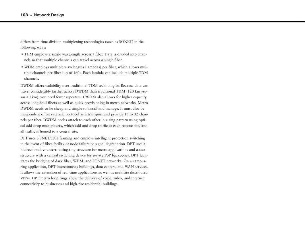
108 • Network Design
differs from time-division multiplexing technologies (such as SONET) in the
following ways:
• TDM employs a single wavelength across a fiber. Data is divided into chan-
nels so that multiple channels can travel across a single fiber.
• WDM employs multiple wavelengths (lambdas) per fiber, which allows mul-
tiple channels per fiber (up to 160). Each lambda can include multiple TDM
channels.
DWDM offers scalability over traditional TDM technologies. Because data can
travel considerably farther across DWDM than traditional TDM (120 km ver-
sus 40 km), you need fewer repeaters. DWDM also allows for higher capacity
across long-haul fibers as well as quick provisioning in metro networks. Metro
DWDM needs to be cheap and simple to install and manage. It must also be
independent of bit rate and protocol as a transport and provide 16 to 32 chan-
nels per fiber. DWDM nodes attach to each other in a ring pattern using opti-
cal add-drop multiplexers, which add and drop traffic at each remote site, and
all traffic is homed to a central site.
DPT uses SONET/SDH framing and employs intelligent protection switching
in the event of fiber facility or node failure or signal degradation. DPT uses a
bidirectional, counterrotating ring structure for metro applications and a star
structure with a central switching device for service PoP backbones. DPT facil-
itates the bridging of dark fiber, WDM, and SONET networks. On a campus-
ring application, DPT interconnects buildings, data centers, and WAN services.
It allows the extension of real-time applications as well as multisite distributed
VPNs. DPT metro loop rings allow the delivery of voice, video, and Internet
connectivity to businesses and high-rise residential buildings.
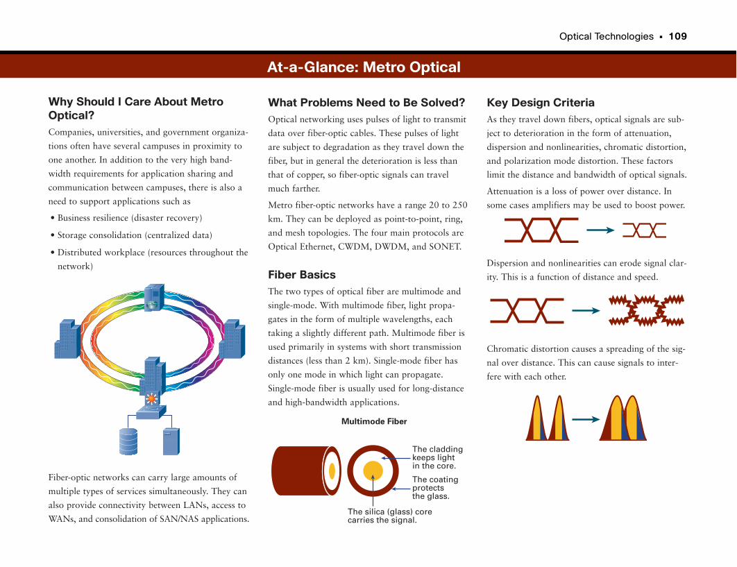
Optical Technologies • 109
Why Should I Care About MetroOptical?Companies, universities, and government organiza-
tions often have several campuses in proximity to
one another. In addition to the very high band-
width requirements for application sharing and
communication between campuses, there is also a
need to support applications such as
• Business resilience (disaster recovery)
• Storage consolidation (centralized data)
• Distributed workplace (resources throughout the
network)
Fiber-optic networks can carry large amounts of
multiple types of services simultaneously. They can
also provide connectivity between LANs, access to
WANs, and consolidation of SAN/NAS applications.
Key Design CriteriaAs they travel down fibers, optical signals are sub-
ject to deterioration in the form of attenuation,
dispersion and nonlinearities, chromatic distortion,
and polarization mode distortion. These factors
limit the distance and bandwidth of optical signals.
Attenuation is a loss of power over distance. In
some cases amplifiers may be used to boost power.
Dispersion and nonlinearities can erode signal clar-
ity. This is a function of distance and speed.
Chromatic distortion causes a spreading of the sig-
nal over distance. This can cause signals to inter-
fere with each other.
What Problems Need to Be Solved?Optical networking uses pulses of light to transmit
data over fiber-optic cables. These pulses of light
are subject to degradation as they travel down the
fiber, but in general the deterioration is less than
that of copper, so fiber-optic signals can travel
much farther.
Metro fiber-optic networks have a range 20 to 250
km. They can be deployed as point-to-point, ring,
and mesh topologies. The four main protocols are
Optical Ethernet, CWDM, DWDM, and SONET.
Fiber BasicsThe two types of optical fiber are multimode and
single-mode. With multimode fiber, light propa-
gates in the form of multiple wavelengths, each
taking a slightly different path. Multimode fiber is
used primarily in systems with short transmission
distances (less than 2 km). Single-mode fiber has
only one mode in which light can propagate.
Single-mode fiber is usually used for long-distance
and high-bandwidth applications.
At-a-Glance: Metro Optical
The silica (glass) core carries the signal.
The claddingkeeps light in the core.
The coatingprotectsthe glass.
Multimode Fiber
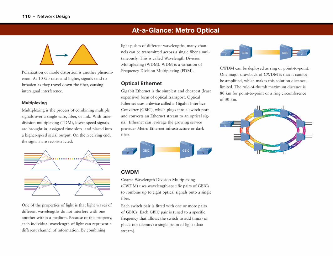
110 • Network Design
Polarization or mode distortion is another phenom-
enon. At 10-Gb rates and higher, signals tend to
broaden as they travel down the fiber, causing
intersignal interference.
Multiplexing
Multiplexing is the process of combining multiple
signals over a single wire, fiber, or link. With time-
division multiplexing (TDM), lower-speed signals
are brought in, assigned time slots, and placed into
a higher-speed serial output. On the receiving end,
the signals are reconstructed.
One of the properties of light is that light waves of
different wavelengths do not interfere with one
another within a medium. Because of this property,
each individual wavelength of light can represent a
different channel of information. By combining
CWDM can be deployed as ring or point-to-point.
One major drawback of CWDM is that it cannot
be amplified, which makes this solution distance-
limited. The rule-of-thumb maximum distance is
80 km for point-to-point or a ring circumference
of 30 km.
light pulses of different wavelengths, many chan-
nels can be transmitted across a single fiber simul-
taneously. This is called Wavelength Division
Multiplexing (WDM). WDM is a variation of
Frequency Division Multiplexing (FDM).
Optical EthernetGigabit Ethernet is the simplest and cheapest (least
expensive) form of optical transport. Optical
Ethernet uses a device called a Gigabit Interface
Converter (GBIC), which plugs into a switch port
and converts an Ethernet stream to an optical sig-
nal. Ethernet can leverage the growing service
provider Metro Ethernet infrastructure or dark
fiber.
CWDMCoarse Wavelength Division Multiplexing
(CWDM) uses wavelength-specific pairs of GBICs
to combine up to eight optical signals onto a single
fiber.
Each switch pair is fitted with one or more pairs
of GBICs. Each GBIC pair is tuned to a specific
frequency that allows the switch to add (mux) or
pluck out (demux) a single beam of light (data
stream).
At-a-Glance: Metro Optical
GBIC GBICV V
GBIC GBICV V
V
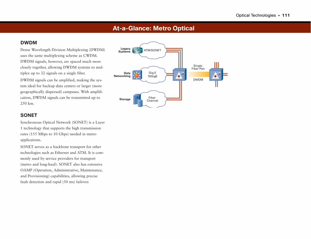
Optical Technologies • 111
DWDMDense Wavelength Division Multiplexing (DWDM)
uses the same multiplexing scheme as CWDM.
DWDM signals, however, are spaced much more
closely together, allowing DWDM systems to mul-
tiplex up to 32 signals on a single fiber.
DWDM signals can be amplified, making the sys-
tem ideal for backup data centers or larger (more
geographically dispersed) campuses. With amplifi-
cation, DWDM signals can be transmitted up to
250 km.
SONETSynchronous Optical Network (SONET) is a Layer
1 technology that supports the high transmission
rates (155 Mbps to 10 Gbps) needed in metro
applications.
SONET serves as a backbone transport for other
technologies such as Ethernet and ATM. It is com-
monly used by service providers for transport
(metro and long-haul). SONET also has extensive
OAMP (Operation, Administrative, Maintenance,
and Provisioning) capabilities, allowing precise
fault detection and rapid (50 ms) failover.
At-a-Glance: Metro Optical
FiberChannel
ATM/SONET
DWDM
SingleFiber Pair
LegacySystems
DataNetworking
Storage
Gig E10GigE

Branch Office Network Designs
Highly centralized companies typically have large centralized networks at one
or a few locations. This allows you to locate your network staff centrally and
focus on the service level of one or a couple campus networks.
This was the typical network of the past, with one or a few rather large head-
quarters locations. If branch offices were required, they typically were connect-
ed to the headquarters location. They provided minimal services, usually just a
nightly synchronization or upload of the day’s transactions, so that the mother
ship could track the progress of sales, inventory, and other important data.
Many companies just had dialup connections, used to upload “batch” data
overnight and download new information from headquarters needed for the
next day’s business.
Loss of connection with the headquarters site often meant that the branch
office was essentially unable to perform day-to-day business transactions until
the connection was restored. This often meant huge productivity drains for
companies with somewhat unreliable connections, and it often resulted in
branch employees feeling like second-class citizens.
Distributed WorkforceIncreasingly, companies are taking advantage of distributed workforces, with
nearly half or even the majority of employees working at locations other than
a headquarters site. With such a significant number of the company’s resources
located remotely, network designs needed to change.
It is no longer acceptable to provide minimal services to branch offices. They
must have the same level of services as a headquarters site. After all, why have
half your workforce be much less productive than those at the headquarters?
Branch office networks therefore must be able to provide the same level of net-
working services as a headquarters network (also called a campus). Not only
must the services be reliable, but they also must be more extensive. Instead of
nightly uploads, branch employees need real-time access to the same applica-
tions and databases of information that headquarters employees have. They
also need access to the same phone services, access to the Internet, wireless,
videoconferencing, e-learning, and many others.
The network design had to evolve to be able to support essentially every head-
quarters network service and application for all branch employees, seamlessly,
as if the branch employees were working at the same location as the headquar-
ters employees.
Distributed Office ChallengesThe norm today for most companies is to have one or a few large headquar-
ters sites, several fairly large regional offices, and a significant number of
branch offices. The number of branch offices often depends on the business
model or industry segment the company is in. For example, a retail store chain
may have two headquarters locations (often one is for geographic redundancy
in case of a catastrophic event) and several hundred or thousand stores (which
are essentially branch offices). Similarly, banks typically have two or three cen-
tral headquarters sites where their data centers are located, and they may have
hundreds or thousands of bank branches. Energy companies may have tens of
thousands of branch locations, such as gas stations.
Distributed offices and workforces mean distributed networks, interconnected
to foster the best communications and network services across the whole com-
pany between employees, no matter where they are working. This presents
challenges, such as how to connect hundreds or thousands of branch office
networks in a scalable way, how to provide reliable network services at some-
times far-flung locations, and how to scale the IT department to manage all
this.
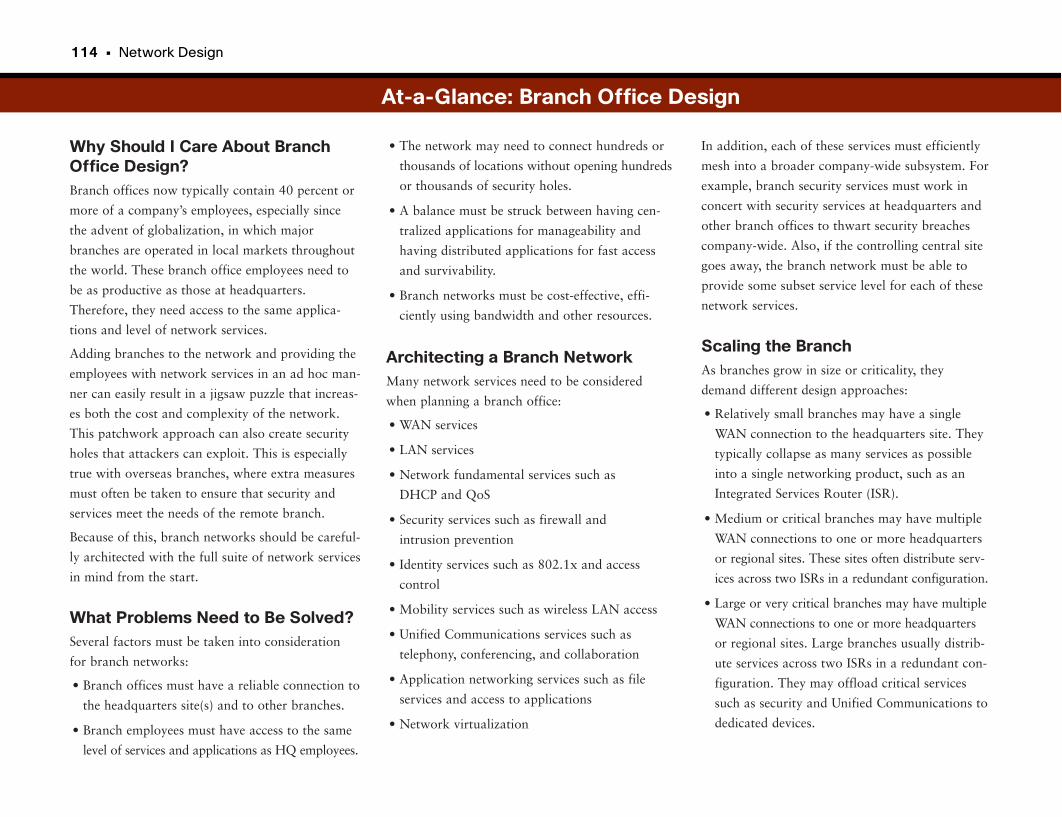
114 • Network Design
Why Should I Care About BranchOffice Design?Branch offices now typically contain 40 percent or
more of a company’s employees, especially since
the advent of globalization, in which major
branches are operated in local markets throughout
the world. These branch office employees need to
be as productive as those at headquarters.
Therefore, they need access to the same applica-
tions and level of network services.
Adding branches to the network and providing the
employees with network services in an ad hoc man-
ner can easily result in a jigsaw puzzle that increas-
es both the cost and complexity of the network.
This patchwork approach can also create security
holes that attackers can exploit. This is especially
true with overseas branches, where extra measures
must often be taken to ensure that security and
services meet the needs of the remote branch.
Because of this, branch networks should be careful-
ly architected with the full suite of network services
in mind from the start.
What Problems Need to Be Solved?Several factors must be taken into consideration
for branch networks:
• Branch offices must have a reliable connection to
the headquarters site(s) and to other branches.
• Branch employees must have access to the same
level of services and applications as HQ employees.
In addition, each of these services must efficiently
mesh into a broader company-wide subsystem. For
example, branch security services must work in
concert with security services at headquarters and
other branch offices to thwart security breaches
company-wide. Also, if the controlling central site
goes away, the branch network must be able to
provide some subset service level for each of these
network services.
Scaling the BranchAs branches grow in size or criticality, they
demand different design approaches:
• Relatively small branches may have a single
WAN connection to the headquarters site. They
typically collapse as many services as possible
into a single networking product, such as an
Integrated Services Router (ISR).
• Medium or critical branches may have multiple
WAN connections to one or more headquarters
or regional sites. These sites often distribute serv-
ices across two ISRs in a redundant configuration.
• Large or very critical branches may have multiple
WAN connections to one or more headquarters
or regional sites. Large branches usually distrib-
ute services across two ISRs in a redundant con-
figuration. They may offload critical services
such as security and Unified Communications to
dedicated devices.
• The network may need to connect hundreds or
thousands of locations without opening hundreds
or thousands of security holes.
• A balance must be struck between having cen-
tralized applications for manageability and
having distributed applications for fast access
and survivability.
• Branch networks must be cost-effective, effi-
ciently using bandwidth and other resources.
Architecting a Branch NetworkMany network services need to be considered
when planning a branch office:
• WAN services
• LAN services
• Network fundamental services such as
DHCP and QoS
• Security services such as firewall and
intrusion prevention
• Identity services such as 802.1x and access
control
• Mobility services such as wireless LAN access
• Unified Communications services such as
telephony, conferencing, and collaboration
• Application networking services such as file
services and access to applications
• Network virtualization
At-a-Glance: Branch Office Design
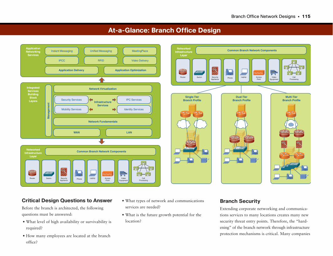
Branch Office Network Designs • 115
Critical Design Questions to AnswerBefore the branch is architected, the following
questions must be answered:
• What level of high availability or survivability is
required?
• How many employees are located at the branch
office?
Branch SecurityExtending corporate networking and communica-
tions services to many locations creates many new
security threat entry points. Therefore, the “hard-
ening” of the branch network through infrastructure
protection mechanisms is critical. Many companies
• What types of network and communications
services are needed?
• What is the future growth potential for the
location?
At-a-Glance: Branch Office Design
Phone
Instant Messaging Unified Messaging MeetingPlace
IPCC RFID Video Delivery
Application Delivery Application Optimization
ApplicationNetworking
Services
Security Services
Network Virtualization
InfrastructureServices
Meeting Place
Mobility Services Video Delivery
IPC Services
Identity Services
Network Fundamentals
WAN
Man
agem
ent
LAN
IntegratedServicesBuilding
BlockLayers
Common Branch Network ComponentsNetworked
InfrastructureLayer
VideoEquipment
SecurityAppliance
CallProcessing
LaptopRouter Switch AccessPoint
Common Branch Network Components
Single-TierBranch Profile
NetworkedInfrastructure
Layer
VideoEquipment
SecurityAppliance
CallProcessing
Router Switch Laptop AccessPoint
Phone
Dual-TierBranch Profile
Multi-TierBranch Profile
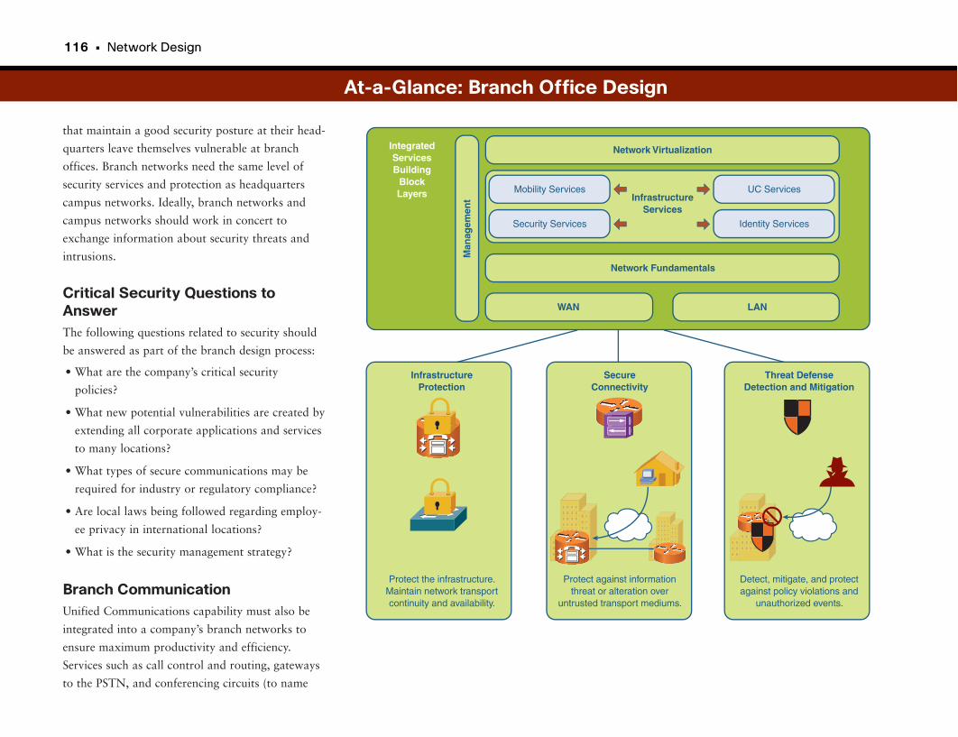
116 • Network Design
that maintain a good security posture at their head-
quarters leave themselves vulnerable at branch
offices. Branch networks need the same level of
security services and protection as headquarters
campus networks. Ideally, branch networks and
campus networks should work in concert to
exchange information about security threats and
intrusions.
Critical Security Questions toAnswerThe following questions related to security should
be answered as part of the branch design process:
• What are the company’s critical security
policies?
• What new potential vulnerabilities are created by
extending all corporate applications and services
to many locations?
• What types of secure communications may be
required for industry or regulatory compliance?
• Are local laws being followed regarding employ-
ee privacy in international locations?
• What is the security management strategy?
Branch CommunicationUnified Communications capability must also be
integrated into a company’s branch networks to
ensure maximum productivity and efficiency.
Services such as call control and routing, gateways
to the PSTN, and conferencing circuits (to name
At-a-Glance: Branch Office Design
Mobility Services
Network Virtualization
InfrastructureServices
Meeting Place
Security Services Video Delivery
UC Services
Identity Services
Network Fundamentals
WAN
Man
agem
ent
LAN
IntegratedServicesBuilding
BlockLayers
InfrastructureProtection
SecureConnectivity
Threat DefenseDetection and Mitigation
Protect the infrastructure.Maintain network transportcontinuity and availability.
Protect against informationthreat or alteration over
untrusted transport mediums.
Detect, mitigate, and protectagainst policy violations and
unauthorized events.
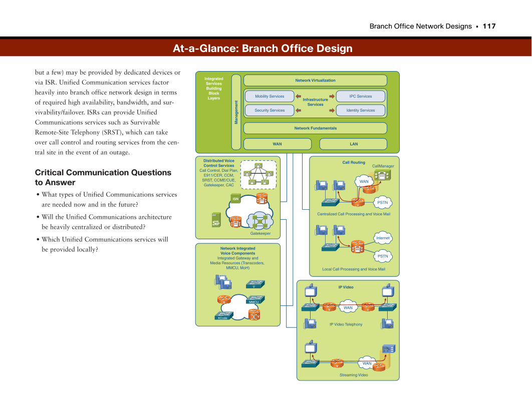
Branch Office Network Designs • 117
but a few) may be provided by dedicated devices or
via ISR. Unified Communication services factor
heavily into branch office network design in terms
of required high availability, bandwidth, and sur-
vivability/failover. ISRs can provide Unified
Communications services such as Survivable
Remote-Site Telephony (SRST), which can take
over call control and routing services from the cen-
tral site in the event of an outage.
Critical Communication Questionsto Answer• What types of Unified Communications services
are needed now and in the future?
• Will the Unified Communications architecture
be heavily centralized or distributed?
• Which Unified Communications services will
be provided locally?
At-a-Glance: Branch Office Design
Mobility Services
Network Virtualization
InfrastructureServices
Meeting Place
Security Services Video Delivery
IPC Services
Identity Services
Network Fundamentals
WAN
Man
agem
ent
LAN
IntegratedServicesBuilding
BlockLayers
Distributed VoiceControl Services
Call Control, Dial Plan,E911/CER, CCM,
SRST, CCME/CUE,Gatekeeper, CAC
Network IntegratedVoice Components
Integrated Gateway andMedia Resources (Transcoders,
MMCU, MoH)
Call Routing
Internet
PSTN
Centralized Call Processing and Voice Mail
Local Call Processing and Voice Mail
IP Video
IP Video Telephony
Streaming Video
CallManager
Gatekeeper
WAN
WAN
PSTN
V
V
V
WANV
V
MMCU
XCode
IP
ISN
V
V
Part IV
Network AvailabilityOne of the most important aspects of networking is keeping the network running—at all times, under any
circumstances, even during times of excessive use or stress. Actually, especially during times of excessive
use or stress. Why? Because a downed network can mean millions of dollars per minute in lost revenue.
Consider a large retailer with 3000 stores that processes hundreds of credit card transactions per minute.
If it cannot accept credit card purchases, it delays or loses sales.
The first section explores the importance and best practices of network availability and resilience, starting
with high availability. It’s always best to avoid a disaster rather than recover from one, and high availabil-
ity refers to the design principles aimed at keeping the network up. “Control Plane Protection” and “QoS
Resiliency” look at using existing networking technologies to help network administrators keep the net-
work running. Control plane protection looks at keeping the “brains” and “heart” of the network work-
ing when the data side is compromised. QoS resiliency is the practice of using a prioritization scheme
(originally developed for maintaining voice over IP quality) to dump traffic that appears to be an attack
on the network to keep the “real” data flowing.
Sometimes it is not possible to avoid network outages despite good designs and proper planning.
“Disaster Recovery” looks at how companies can best prepare to get the network up and the data
restored in the event of an unavoidable outage, or possibly loss of a site.
The final topic is network management. Some large companies have an entire staff of IT professionals
dedicated to managing the network to ensure that it operates efficiently. This section provides a view into
what it takes to run a network.
High Availability 121
Control Plane 129
Quality of Service and 133
Network Availability
Disaster Recovery 139
Network Management 147

High Availability
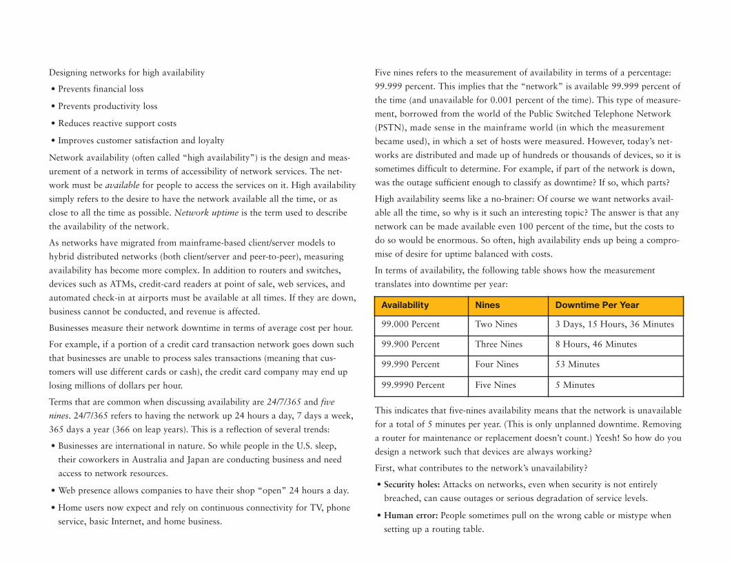
Five nines refers to the measurement of availability in terms of a percentage:
99.999 percent. This implies that the “network” is available 99.999 percent of
the time (and unavailable for 0.001 percent of the time). This type of measure-
ment, borrowed from the world of the Public Switched Telephone Network
(PSTN), made sense in the mainframe world (in which the measurement
became used), in which a set of hosts were measured. However, today’s net-
works are distributed and made up of hundreds or thousands of devices, so it is
sometimes difficult to determine. For example, if part of the network is down,
was the outage sufficient enough to classify as downtime? If so, which parts?
High availability seems like a no-brainer: Of course we want networks avail-
able all the time, so why is it such an interesting topic? The answer is that any
network can be made available even 100 percent of the time, but the costs to
do so would be enormous. So often, high availability ends up being a compro-
mise of desire for uptime balanced with costs.
In terms of availability, the following table shows how the measurement
translates into downtime per year:
This indicates that five-nines availability means that the network is unavailable
for a total of 5 minutes per year. (This is only unplanned downtime. Removing
a router for maintenance or replacement doesn’t count.) Yeesh! So how do you
design a network such that devices are always working?
First, what contributes to the network’s unavailability?
• Security holes: Attacks on networks, even when security is not entirely
breached, can cause outages or serious degradation of service levels.
• Human error: People sometimes pull on the wrong cable or mistype when
setting up a routing table.
Designing networks for high availability
• Prevents financial loss
• Prevents productivity loss
• Reduces reactive support costs
• Improves customer satisfaction and loyalty
Network availability (often called “high availability”) is the design and meas-
urement of a network in terms of accessibility of network services. The net-
work must be available for people to access the services on it. High availability
simply refers to the desire to have the network available all the time, or as
close to all the time as possible. Network uptime is the term used to describe
the availability of the network.
As networks have migrated from mainframe-based client/server models to
hybrid distributed networks (both client/server and peer-to-peer), measuring
availability has become more complex. In addition to routers and switches,
devices such as ATMs, credit-card readers at point of sale, web services, and
automated check-in at airports must be available at all times. If they are down,
business cannot be conducted, and revenue is affected.
Businesses measure their network downtime in terms of average cost per hour.
For example, if a portion of a credit card transaction network goes down such
that businesses are unable to process sales transactions (meaning that cus-
tomers will use different cards or cash), the credit card company may end up
losing millions of dollars per hour.
Terms that are common when discussing availability are 24/7/365 and five
nines. 24/7/365 refers to having the network up 24 hours a day, 7 days a week,
365 days a year (366 on leap years). This is a reflection of several trends:
• Businesses are international in nature. So while people in the U.S. sleep,
their coworkers in Australia and Japan are conducting business and need
access to network resources.
• Web presence allows companies to have their shop “open” 24 hours a day.
• Home users now expect and rely on continuous connectivity for TV, phone
service, basic Internet, and home business.
Availability Nines Downtime Per Year
99.000 Percent Two Nines 3 Days, 15 Hours, 36 Minutes
99.900 Percent Three Nines 8 Hours, 46 Minutes
99.990 Percent Four Nines 53 Minutes
99.9990 Percent Five Nines 5 Minutes
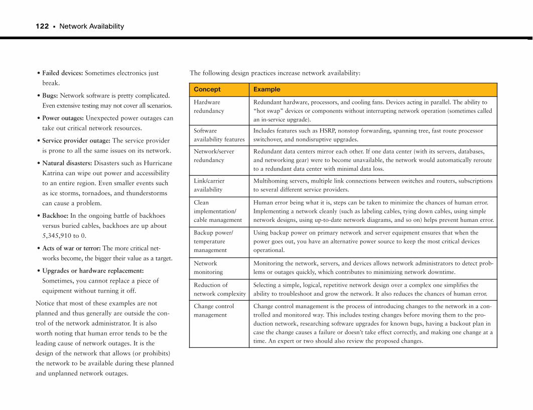
122 • Network Availability
• Failed devices: Sometimes electronics just
break.
• Bugs: Network software is pretty complicated.
Even extensive testing may not cover all scenarios.
• Power outages: Unexpected power outages can
take out critical network resources.
• Service provider outage: The service provider
is prone to all the same issues on its network.
• Natural disasters: Disasters such as Hurricane
Katrina can wipe out power and accessibility
to an entire region. Even smaller events such
as ice storms, tornadoes, and thunderstorms
can cause a problem.
• Backhoe: In the ongoing battle of backhoes
versus buried cables, backhoes are up about
5,345,910 to 0.
• Acts of war or terror: The more critical net-
works become, the bigger their value as a target.
• Upgrades or hardware replacement:
Sometimes, you cannot replace a piece of
equipment without turning it off.
Notice that most of these examples are not
planned and thus generally are outside the con-
trol of the network administrator. It is also
worth noting that human error tends to be the
leading cause of network outages. It is the
design of the network that allows (or prohibits)
the network to be available during these planned
and unplanned network outages.
The following design practices increase network availability:
Concept Example
Hardwareredundancy
Redundant hardware, processors, and cooling fans. Devices acting in parallel. The ability to“hot swap” devices or components without interrupting network operation (sometimes calledan in-service upgrade).
Softwareavailability features
Includes features such as HSRP, nonstop forwarding, spanning tree, fast route processorswitchover, and nondisruptive upgrades.
Network/serverredundancy
Redundant data centers mirror each other. If one data center (with its servers, databases,and networking gear) were to become unavailable, the network would automatically rerouteto a redundant data center with minimal data loss.
Link/carrieravailability
Multihoming servers, multiple link connections between switches and routers, subscriptionsto several different service providers.
Cleanimplementation/cable management
Human error being what it is, steps can be taken to minimize the chances of human error.Implementing a network cleanly (such as labeling cables, tying down cables, using simplenetwork designs, using up-to-date network diagrams, and so on) helps prevent human error.
Backup power/temperaturemanagement
Using backup power on primary network and server equipment ensures that when thepower goes out, you have an alternative power source to keep the most critical devicesoperational.
Networkmonitoring
Monitoring the network, servers, and devices allows network administrators to detect prob-lems or outages quickly, which contributes to minimizing network downtime.
Reduction of network complexity
Selecting a simple, logical, repetitive network design over a complex one simplifies the ability to troubleshoot and grow the network. It also reduces the chances of human error.
Change control management
Change control management is the process of introducing changes to the network in a con-trolled and monitored way. This includes testing changes before moving them to the pro-duction network, researching software upgrades for known bugs, having a backout plan incase the change causes a failure or doesn’t take effect correctly, and making one change at atime. An expert or two should also review the proposed changes.
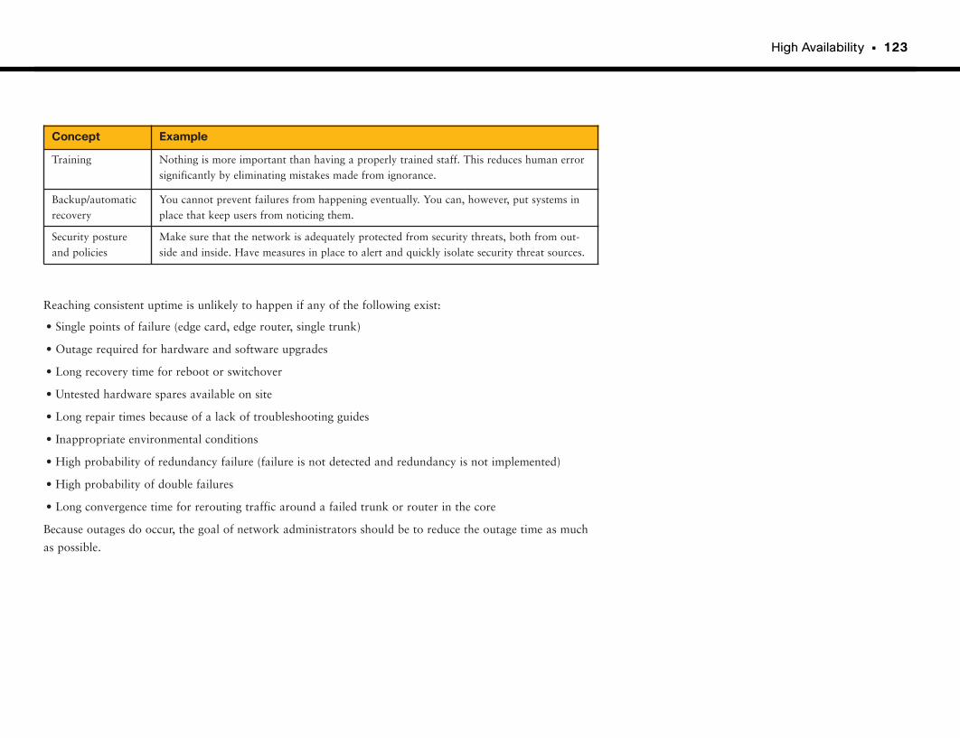
High Availability • 123
Reaching consistent uptime is unlikely to happen if any of the following exist:
• Single points of failure (edge card, edge router, single trunk)
• Outage required for hardware and software upgrades
• Long recovery time for reboot or switchover
• Untested hardware spares available on site
• Long repair times because of a lack of troubleshooting guides
• Inappropriate environmental conditions
• High probability of redundancy failure (failure is not detected and redundancy is not implemented)
• High probability of double failures
• Long convergence time for rerouting traffic around a failed trunk or router in the core
Because outages do occur, the goal of network administrators should be to reduce the outage time as much
as possible.
Concept Example
Training Nothing is more important than having a properly trained staff. This reduces human errorsignificantly by eliminating mistakes made from ignorance.
Backup/automaticrecovery
You cannot prevent failures from happening eventually. You can, however, put systems inplace that keep users from noticing them.
Security posture and policies
Make sure that the network is adequately protected from security threats, both from out-side and inside. Have measures in place to alert and quickly isolate security threat sources.
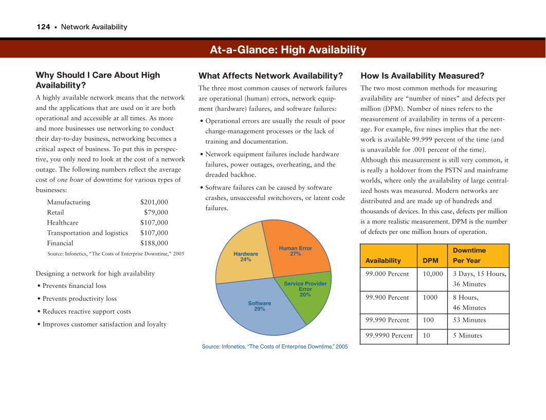
124 • Network Availability
Why Should I Care About HighAvailability?A highly available network means that the network
and the applications that are used on it are both
operational and accessible at all times. As more
and more businesses use networking to conduct
their day-to-day business, networking becomes a
critical aspect of business. To put this in perspec-
tive, you only need to look at the cost of a network
outage. The following numbers reflect the average
cost of one hour of downtime for various types of
businesses:
Manufacturing $201,000
Retail $79,000
Healthcare $107,000
Transportation and logistics $107,000
Financial $188,000
Designing a network for high availability
• Prevents financial loss
• Prevents productivity loss
• Reduces reactive support costs
• Improves customer satisfaction and loyalty
What Affects Network Availability?The three most common causes of network failures
are operational (human) errors, network equip-
ment (hardware) failures, and software failures:
• Operational errors are usually the result of poor
change-management processes or the lack of
training and documentation.
• Network equipment failures include hardware
failures, power outages, overheating, and the
dreaded backhoe.
• Software failures can be caused by software
crashes, unsuccessful switchovers, or latent code
failures.
At-a-Glance: High Availability
How Is Availability Measured?The two most common methods for measuring
availability are “number of nines” and defects per
million (DPM). Number of nines refers to the
measurement of availability in terms of a percent-
age. For example, five nines implies that the net-
work is available 99.999 percent of the time (and
is unavailable for .001 percent of the time).
Although this measurement is still very common, it
is really a holdover from the PSTN and mainframe
worlds, where only the availability of large central-
ized hosts was measured. Modern networks are
distributed and are made up of hundreds and
thousands of devices. In this case, defects per million
is a more realistic measurement. DPM is the number
of defects per one million hours of operation.
Source: Infonetics, “The Costs of Enterprise Downtime,” 2005 Hardware24%
Software29%
Service ProviderError20%
Human Error27%
Source: Infonetics, “The Costs of Enterprise Downtime,” 2005
Availability DPM
Downtime
Per Year
99.000 Percent 10,000 3 Days, 15 Hours,
36 Minutes
99.900 Percent 1000 8 Hours,
46 Minutes
99.990 Percent 100 53 Minutes
99.9990 Percent 10 5 Minutes
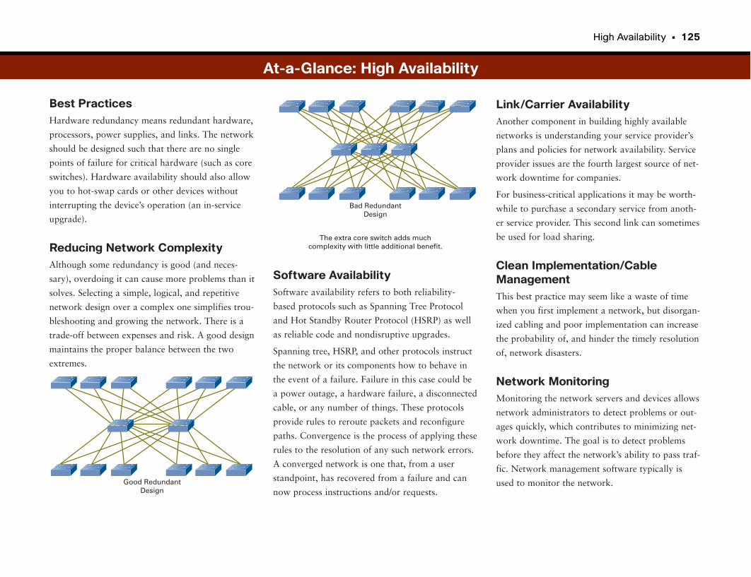
High Availability • 125
Best PracticesHardware redundancy means redundant hardware,
processors, power supplies, and links. The network
should be designed such that there are no single
points of failure for critical hardware (such as core
switches). Hardware availability should also allow
you to hot-swap cards or other devices without
interrupting the device’s operation (an in-service
upgrade).
Reducing Network ComplexityAlthough some redundancy is good (and neces-
sary), overdoing it can cause more problems than it
solves. Selecting a simple, logical, and repetitive
network design over a complex one simplifies trou-
bleshooting and growing the network. There is a
trade-off between expenses and risk. A good design
maintains the proper balance between the two
extremes.
Link/Carrier AvailabilityAnother component in building highly available
networks is understanding your service provider’s
plans and policies for network availability. Service
provider issues are the fourth largest source of net-
work downtime for companies.
For business-critical applications it may be worth-
while to purchase a secondary service from anoth-
er service provider. This second link can sometimes
be used for load sharing.
Clean Implementation/CableManagementThis best practice may seem like a waste of time
when you first implement a network, but disorgan-
ized cabling and poor implementation can increase
the probability of, and hinder the timely resolution
of, network disasters.
Network MonitoringMonitoring the network servers and devices allows
network administrators to detect problems or out-
ages quickly, which contributes to minimizing net-
work downtime. The goal is to detect problems
before they affect the network’s ability to pass traf-
fic. Network management software typically is
used to monitor the network.
Software AvailabilitySoftware availability refers to both reliability-
based protocols such as Spanning Tree Protocol
and Hot Standby Router Protocol (HSRP) as well
as reliable code and nondisruptive upgrades.
Spanning tree, HSRP, and other protocols instruct
the network or its components how to behave in
the event of a failure. Failure in this case could be
a power outage, a hardware failure, a disconnected
cable, or any number of things. These protocols
provide rules to reroute packets and reconfigure
paths. Convergence is the process of applying these
rules to the resolution of any such network errors.
A converged network is one that, from a user
standpoint, has recovered from a failure and can
now process instructions and/or requests.
At-a-Glance: High Availability
Good RedundantDesign
The extra core switch adds muchcomplexity with little additional benefit.
Bad RedundantDesign
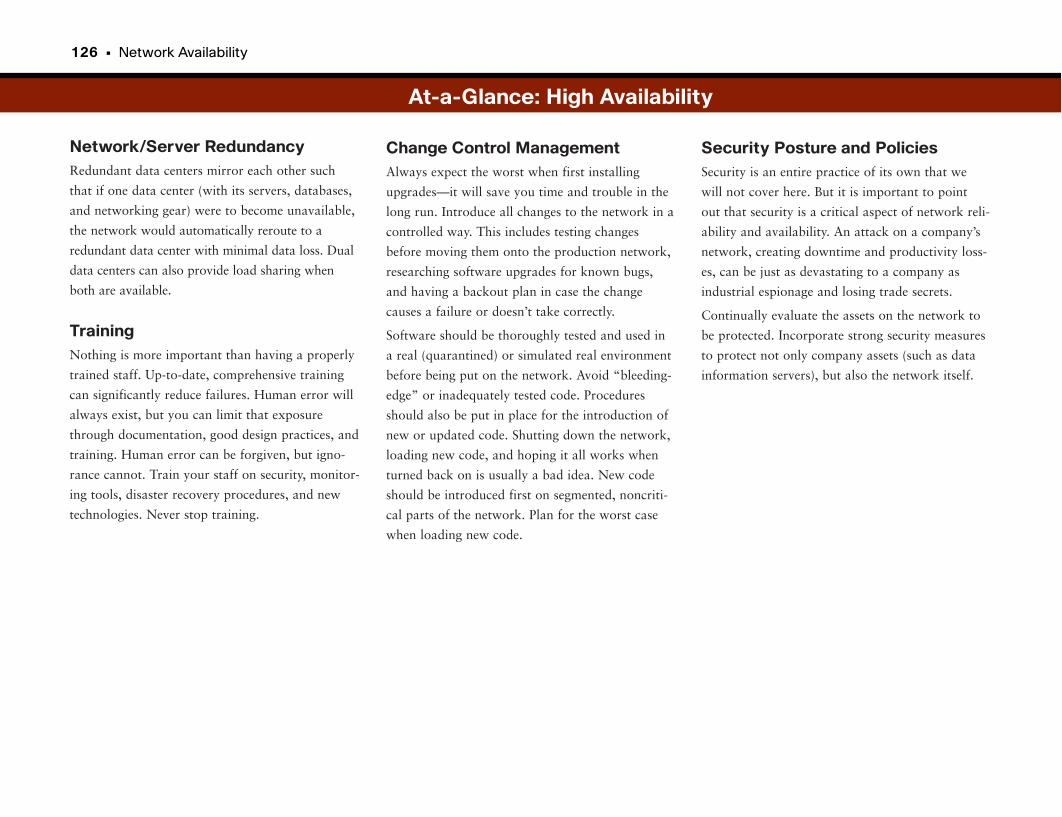
126 • Network Availability
Network/Server RedundancyRedundant data centers mirror each other such
that if one data center (with its servers, databases,
and networking gear) were to become unavailable,
the network would automatically reroute to a
redundant data center with minimal data loss. Dual
data centers can also provide load sharing when
both are available.
TrainingNothing is more important than having a properly
trained staff. Up-to-date, comprehensive training
can significantly reduce failures. Human error will
always exist, but you can limit that exposure
through documentation, good design practices, and
training. Human error can be forgiven, but igno-
rance cannot. Train your staff on security, monitor-
ing tools, disaster recovery procedures, and new
technologies. Never stop training.
Security Posture and PoliciesSecurity is an entire practice of its own that we
will not cover here. But it is important to point
out that security is a critical aspect of network reli-
ability and availability. An attack on a company’s
network, creating downtime and productivity loss-
es, can be just as devastating to a company as
industrial espionage and losing trade secrets.
Continually evaluate the assets on the network to
be protected. Incorporate strong security measures
to protect not only company assets (such as data
information servers), but also the network itself.
Change Control ManagementAlways expect the worst when first installing
upgrades—it will save you time and trouble in the
long run. Introduce all changes to the network in a
controlled way. This includes testing changes
before moving them onto the production network,
researching software upgrades for known bugs,
and having a backout plan in case the change
causes a failure or doesn’t take correctly.
Software should be thoroughly tested and used in
a real (quarantined) or simulated real environment
before being put on the network. Avoid “bleeding-
edge” or inadequately tested code. Procedures
should also be put in place for the introduction of
new or updated code. Shutting down the network,
loading new code, and hoping it all works when
turned back on is usually a bad idea. New code
should be introduced first on segmented, noncriti-
cal parts of the network. Plan for the worst case
when loading new code.
At-a-Glance: High Availability

This page intentionally left blank
Control Plane
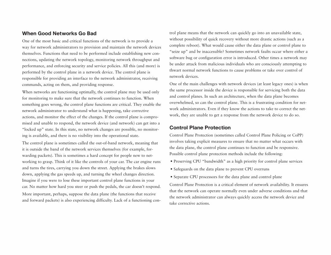
When Good Networks Go BadOne of the most basic and critical functions of the network is to provide a
way for network administrators to provision and maintain the network devices
themselves. Functions that need to be performed include establishing new con-
nections, updating the network topology, monitoring network throughput and
performance, and enforcing security and service policies. All this (and more) is
performed by the control plane in a network device. The control plane is
responsible for providing an interface to the network administrator, receiving
commands, acting on them, and providing response.
When networks are functioning optimally, the control plane may be used only
for monitoring to make sure that the network continues to function. When
something goes wrong, the control plane functions are critical. They enable the
network administrator to understand what is happening, take corrective
actions, and monitor the effect of the changes. If the control plane is compro-
mised and unable to respond, the network device (and network) can get into a
“locked up” state. In this state, no network changes are possible, no monitor-
ing is available, and there is no visibility into the operational state.
The control plane is sometimes called the out-of-band network, meaning that
it is outside the band of the network services themselves (for example, for-
warding packets). This is sometimes a hard concept for people new to net-
working to grasp. Think of it like the controls of your car. The car engine runs
and turns the tires, carrying you down the street. Applying the brakes slows
down, applying the gas speeds up, and turning the wheel changes direction.
Imagine if you were to lose these important control plane functions in your
car. No matter how hard you steer or push the pedals, the car doesn’t respond.
More important, perhaps, suppose the data plane (the functions that receive
and forward packets) is also experiencing difficulty. Lack of a functioning con-
trol plane means that the network can quickly go into an unavailable state,
without possibility of quick recovery without more drastic actions (such as a
complete reboot). What would cause either the data plane or control plane to
“seize up” and be inaccessible? Sometimes network faults occur where either a
software bug or configuration error is introduced. Other times a network may
be under attack from malicious individuals who are consciously attempting to
thwart normal network functions to cause problems or take over control of
network devices.
One of the main challenges with network devices (at least legacy ones) is when
the same processor inside the device is responsible for servicing both the data
and control planes. In such an architecture, when the data plane becomes
overwhelmed, so can the control plane. This is a frustrating condition for net-
work administrators. Even if they know the actions to take to correct the net-
work, they are unable to get a response from the network device to do so.
Control Plane ProtectionControl Plane Protection (sometimes called Control Plane Policing or CoPP)
involves taking explicit measures to ensure that no matter what occurs with
the data plane, the control plane continues to function and be responsive.
Possible control plane protection methods include the following:
• Preserving CPU “bandwidth” as a high priority for control plane services
• Safeguards on the data plane to prevent CPU overruns
• Separate CPU processors for the data plane and control plane
Control Plane Protection is a critical element of network availability. It ensures
that the network can operate normally even under adverse conditions and that
the network administrator can always quickly access the network device and
take corrective actions.
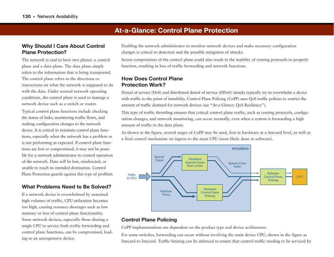
130 • Network Availability
Why Should I Care About ControlPlane Protection?The network is said to have two planes: a control
plane and a data plane. The data plane simply
refers to the information that is being transported.
The control plane refers to the directions or
instructions on what the network is supposed to do
with the data. Under normal network operating
conditions, the control plane is used to manage a
network device such as a switch or router.
Typical control plane functions include checking
the status of links, monitoring traffic flows, and
making configuration changes to the network
device. It is critical to maintain control plane func-
tions, especially when the network has a problem or
is not performing as expected. If control plane func-
tions are lost or compromised, it may not be possi-
ble for a network administrator to control operation
of the network. Data will be lost, misdirected, or
unable to reach its intended destination. Control
Plane Protection guards against this type of problem.
What Problems Need to Be Solved?If a network device is overwhelmed by sustained
high volumes of traffic, CPU utilization becomes
too high, causing resource shortages such as low
memory or loss of control plane functionality.
Some network devices, especially those sharing a
single CPU to service both traffic forwarding and
control plane functions, can be compromised, lead-
ing to an unresponsive device.
Control Plane PolicingCoPP implementations are dependent on the product type and device architecture.
For some switches, forwarding can occur without involving the main device CPU, shown in the figure as
linecard to linecard. Traffic limiting can be enforced to ensure that control traffic needing to be serviced by
Enabling the network administrator to monitor network devices and make necessary configuration
changes is critical to detection and the possible mitigation of attacks.
Severe compromises of the control plane could also result in the inability of routing protocols to properly
function, resulting in loss of traffic forwarding and network functions.
How Does Control Plane Protection Work?Denial of service (DoS) and distributed denial of service (DDoS) attacks typically try to overwhelm a device
with traffic to the point of instability. Control Plane Policing (CoPP) uses QoS traffic policies to restrict the
amount of traffic destined for network devices (see “At-a-Glance: QoS Resiliency”).
This type of traffic throttling ensures that critical control plane traffic, such as routing protocols, configu-
ration changes, and network monitoring, can occur normally, even when a system is forwarding a high
amount of traffic in the data plane.
As shown in the figure, several stages of CoPP may be used, first in hardware at a linecard level, as well as
a final control mechanism on ingress to the main CPU (most likely done in software).
At-a-Glance: Control Plane Protection
Trafficto CPU
SpecialCases
MatchesPolicy
Special-CaseTraffic
PFC3/DFC3
SoftwareControl-Plane
PolicingCPU
HardwareSpecial-CasesRate Limiter
HardwareControl-Plane
Policing
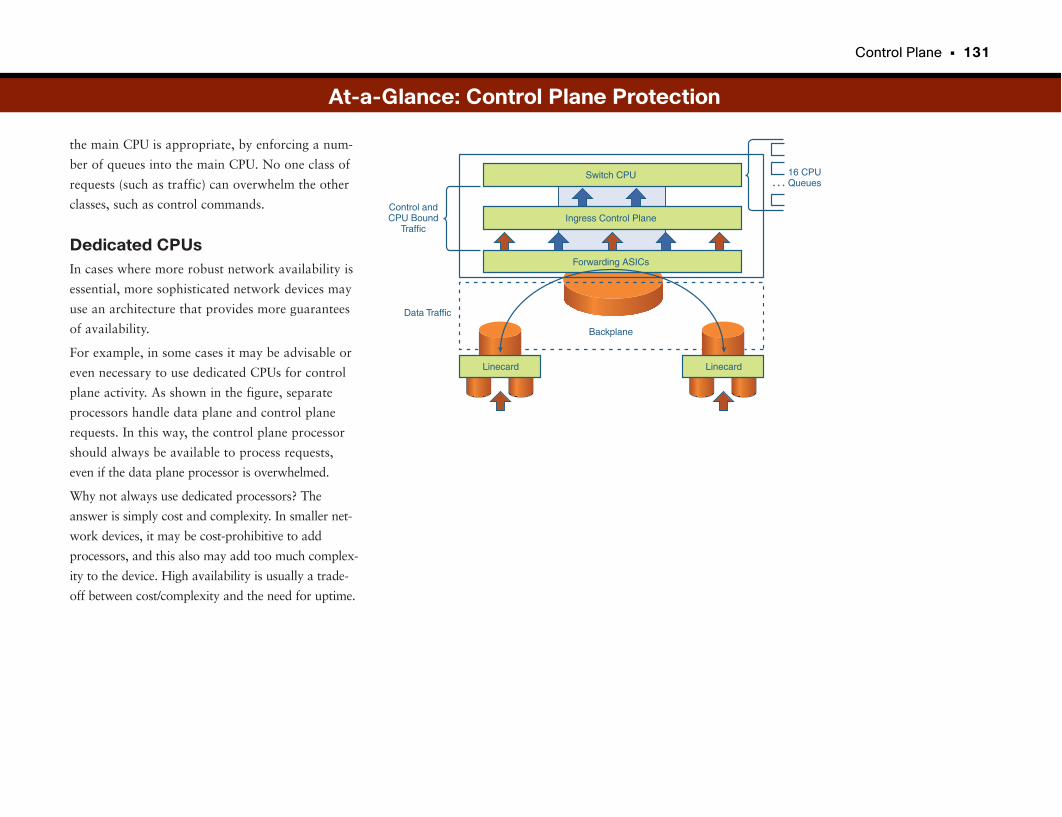
Control Plane • 131
the main CPU is appropriate, by enforcing a num-
ber of queues into the main CPU. No one class of
requests (such as traffic) can overwhelm the other
classes, such as control commands.
Dedicated CPUsIn cases where more robust network availability is
essential, more sophisticated network devices may
use an architecture that provides more guarantees
of availability.
For example, in some cases it may be advisable or
even necessary to use dedicated CPUs for control
plane activity. As shown in the figure, separate
processors handle data plane and control plane
requests. In this way, the control plane processor
should always be available to process requests,
even if the data plane processor is overwhelmed.
Why not always use dedicated processors? The
answer is simply cost and complexity. In smaller net-
work devices, it may be cost-prohibitive to add
processors, and this also may add too much complex-
ity to the device. High availability is usually a trade-
off between cost/complexity and the need for uptime.
16 CPUQueues
Forwarding ASICs
Ingress Control Plane
Switch CPU
Control andCPU Bound
Traffic
Data Traffic
Linecard
Backplane
Linecard
…
At-a-Glance: Control Plane Protection
Quality of Service and Network Availability
Quality of Service as Network Protection?Quality of Service (QoS) is commonly used in networks to provide prioritiza-
tion of critical network traffic or traffic with special requirements. For exam-
ple, in a converged network with data and other types of traffic such as voice
over IP (VoIP) and video over IP (see Part VII, “Unified Communications”),
QoS is used to manage the special requirements of voice and video communi-
cations, providing low delay (typically less than 250 milliseconds end-to-end),
low jitter (typically less than 10 or 20 milliseconds), and low packet loss (typi-
cally less than 0.5 percent of packets). Exceeding these values can cause poor-
quality VoIP calls and frustrate users.
QoS also has a role to play in highly available networks. Often when one or
more devices (such as laptops) on the network have been compromised with
malicious software, such as a virus or worm, they can be used as a launching
point for attacks on other parts of the network, such as network devices or
application servers. If such an attack comes from outside the network, such as
from the Internet, or from a single laptop on the network, it can often be easi-
ly recognized and halted, if not prevented. However, when attacks originate
from several or many devices, and those same devices appear to be sending
legitimate traffic over the network, they can be very difficult to locate and halt.
Scavenger QoSScavenger QoS operates on the principle that if we know a typical applica-
tion’s behavior on a device and on the network, we can build safeguards into
the network to recognize and stop an application if it is not behaving normally.
For example, if we know that a particular port on the network has an IP-
enabled telephone connected to it, and we know that device normally transmits
less than, say, 150 kbps of RTP traffic packets, and suddenly we see more than
4 Mbps of RTP traffic from that port, an anomaly exists. This might indicate a
malfunctioning or compromised device. Worse yet is that this traffic typically
is marked extremely high priority in the network to preserve voice quality.
Scavenger QoS works by defining limits on ports that if a configured traffic
limit is exceeded, the packets exceeding the limits are remarked to a much
lower priority that essentially tells the network it is okay to transmit these
packets whenever it has the time. If the network is under severe congestion
(meaning that it is getting overwhelmed with traffic), it might be okay to
“starve” the traffic marked as Scavenger class, meaning that it gets delayed to
the point where it is dropped.
Scavenger QoS is almost “anti-QoS” in the sense that when used in this way
QoS has the opposite effect of QoS for voice-quality applications (discussed
later in this book). In short, QoS typically identifies critical traffic types (such
as voice traffic) and raises these packets’ priority on the network. Scavenger
QoS identifies certain types of traffic and then lowers these packets’ priority
on the network. This difference is key.
Building such safeguards into the network is another step in keeping a highly
available network functioning, even when devices malfunction severely. Or a
security threat may be in progress, attempting to compromise either the net-
work’s availability or integrity.
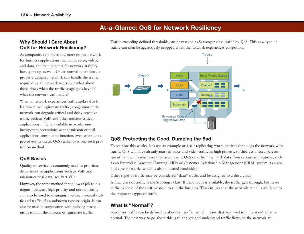
134 • Network Availability
Why Should I Care About QoS for Network Resiliency?As companies rely more and more on the network
for business applications, including voice, video,
and data, the requirements for network stability
have gone up as well. Under normal operations, a
properly designed network can handle the traffic
required by all network users. But what about
those times when the traffic usage goes beyond
what the network can handle?
When a network experiences traffic spikes due to
legitimate or illegitimate traffic, congestion in the
network can degrade critical and delay-sensitive
traffic such as VoIP and other mission-critical
applications. Highly available networks must
incorporate protections so that mission-critical
applications continue to function, even when unex-
pected events occur. QoS resiliency is one such pro-
tection method.
QoS BasicsQuality of service is commonly used to prioritize
delay-sensitive applications such as VoIP and
mission-critical data (see Part VII).
However, the same method that allows QoS to dis-
tinguish between high-priority and normal traffic
can also be used to distinguish between normal traf-
fic and traffic of an unknown type or origin. It can
also be used in conjunction with policing mecha-
nisms to limit the amount of legitimate traffic.
QoS: Protecting the Good, Dumping the BadTo see how this works, let’s use an example of a self-replicating worm or virus that clogs the network with
traffic. QoS will have already marked voice and video traffic as high priority, so they get a fixed percent-
age of bandwidth whenever they are present. QoS can also now mark data from certain applications, such
as an Enterprise Resource Planning (ERP) or Customer Relationship Management (CRM) system, as a sec-
ond class of traffic, which is also allocated bandwidth.
Other types of traffic may be considered “data” traffic and be assigned to a third class.
A final class of traffic is the Scavenger class. If bandwidth is available, the traffic gets through, but never
at the expense of the stuff we need to run the business. This ensures that the network remains available to
the important types of traffic.
What Is “Normal”?Scavenger traffic can be defined as abnormal traffic, which means that you need to understand what is
normal. The best way to go about this is to analyze and understand traffic flows on the network at
Traffic exceeding defined thresholds can be marked as Scavenger class traffic by QoS. This new type of
traffic can then be aggressively dropped when the network experiences congestion.
At-a-Glance: QoS for Network Resiliency
Data
Scavenger
Voice Strict Priority Queue
Scavenger QueueAggressive Drop
Classify
Throttle
Gold Queue 1
Queue 2
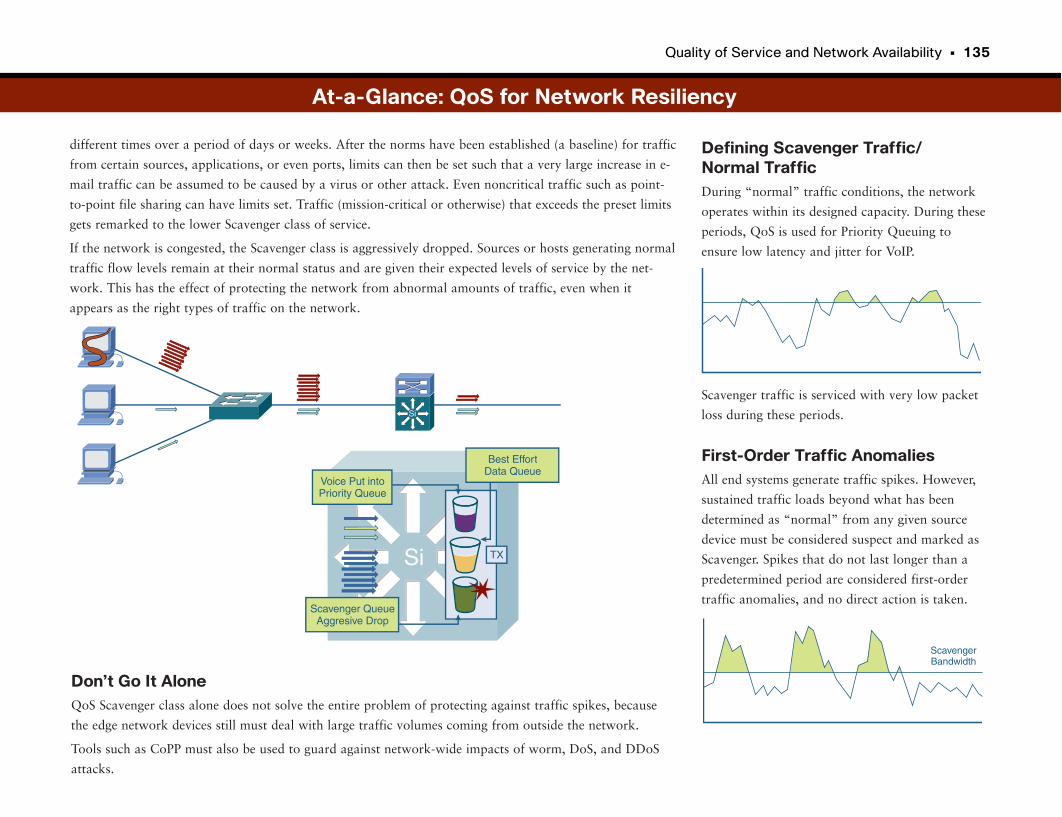
Quality of Service and Network Availability • 135
different times over a period of days or weeks. After the norms have been established (a baseline) for traffic
from certain sources, applications, or even ports, limits can then be set such that a very large increase in e-
mail traffic can be assumed to be caused by a virus or other attack. Even noncritical traffic such as point-
to-point file sharing can have limits set. Traffic (mission-critical or otherwise) that exceeds the preset limits
gets remarked to the lower Scavenger class of service.
If the network is congested, the Scavenger class is aggressively dropped. Sources or hosts generating normal
traffic flow levels remain at their normal status and are given their expected levels of service by the net-
work. This has the effect of protecting the network from abnormal amounts of traffic, even when it
appears as the right types of traffic on the network.
Defining Scavenger Traffic/Normal TrafficDuring “normal” traffic conditions, the network
operates within its designed capacity. During these
periods, QoS is used for Priority Queuing to
ensure low latency and jitter for VoIP.
Scavenger traffic is serviced with very low packet
loss during these periods.
First-Order Traffic AnomaliesAll end systems generate traffic spikes. However,
sustained traffic loads beyond what has been
determined as “normal” from any given source
device must be considered suspect and marked as
Scavenger. Spikes that do not last longer than a
predetermined period are considered first-order
traffic anomalies, and no direct action is taken.
Don’t Go It AloneQoS Scavenger class alone does not solve the entire problem of protecting against traffic spikes, because
the edge network devices still must deal with large traffic volumes coming from outside the network.
Tools such as CoPP must also be used to guard against network-wide impacts of worm, DoS, and DDoS
attacks.
Si
Voice Put intoPriority Queue
Si
TX
Best EffortData Queue
Scavenger QueueAggresive Drop
At-a-Glance: QoS for Network Resiliency
ScavengerBandwidth
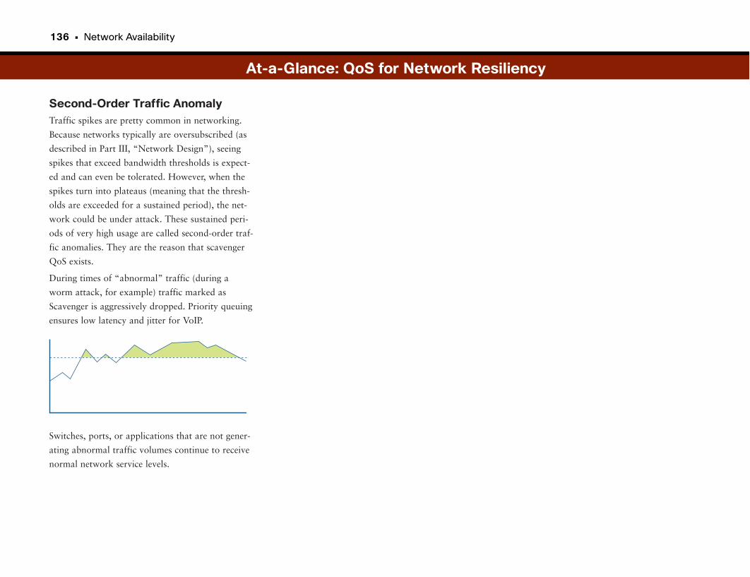
136 • Network Availability
Second-Order Traffic AnomalyTraffic spikes are pretty common in networking.
Because networks typically are oversubscribed (as
described in Part III, “Network Design”), seeing
spikes that exceed bandwidth thresholds is expect-
ed and can even be tolerated. However, when the
spikes turn into plateaus (meaning that the thresh-
olds are exceeded for a sustained period), the net-
work could be under attack. These sustained peri-
ods of very high usage are called second-order traf-
fic anomalies. They are the reason that scavenger
QoS exists.
During times of “abnormal” traffic (during a
worm attack, for example) traffic marked as
Scavenger is aggressively dropped. Priority queuing
ensures low latency and jitter for VoIP.
Switches, ports, or applications that are not gener-
ating abnormal traffic volumes continue to receive
normal network service levels.
At-a-Glance: QoS for Network Resiliency

This page intentionally left blank

Disaster Recovery
What Happens When the Network Stops WorkingDisaster recovery (DR) is the planning process for how you restore network
and computer services or continue operating in the event of a natural or
human disaster. The process includes identifying the hardware and software
required to run business-critical applications and the associated processes that
provide a smooth transition from the event. A DR plan assesses the loss of
time and loss of data that are acceptable to the business. Within those limits,
DR moves processing to an alternative location after a catastrophic event. The
alternative location must have all the components of the production site
already in place before the disaster. The move to an alternative location
requires an understanding of five key components:
• Equipment: What equipment is affected? Which servers, disks, and networks?
• Data: Which databases and data are affected?
• People: Who is responsible for recovery?
• Location: Where does the recovery take place?
• Network: How do we switch the network to the recovery location?
Statistically, fire is the leading cause of disaster. Examples of other possible dis-
asters include storms, floods, earthquakes, chemical accidents, nuclear acci-
dents, wars, terrorist attacks, cold winter weather, extreme heat, and airplane
crashes (loss of key staff). The planning process includes all the different loca-
tions and determines the political stability of the critical business locations. For
each possible disaster that could affect a site, the disaster team assesses the
impact on the business in advance. The team addresses the following questions:
• How much of the organization’s resources (including data, equipment, and
staff) could be lost? What are the replacement costs?
• What efforts would be required to rebuild?
• How long would it take to recover?
• What would be the impact on the overall organization?
• What customers would be affected? What would be the impact on them?
• How much would the disaster affect the share price and market confidence?
DR PlanningAfter outlining possible threats, the DR team ranks the services and systems
according to three categories: mission-critical, important, and not so impor-
tant. The ranking determines the depth of planning, funding, and resiliency. A
DR team takes the following steps:
STEP 1 Form a planning group.
STEP 2 Perform risk assessments and audits.
STEP 3 Establish priorities for the network and applications.
STEP 4 Develop recovery strategies.
STEP 5 Prepare an up-to-date inventory and documentation of the plan.
STEP 6 Develop verification criteria and procedures.
STEP 7 Implement the plan.
STEP 8 Perform periodic drills to ensure that staff remains ready.
The team identifies recovery action for the applications staff, system adminis-
trators, database administrators, and network staff.
140 • Network Availability
Resiliency and Backup ServicesBusiness resiliency is the ability to recover from any network failure or issue,
whether it is related to disaster, link failures, hardware, design, or network
services. A highly available network (built for resiliency) is the bedrock of
effective and timely disaster recovery. Consider the following areas of the net-
work for resiliency:
• Network links
— Carrier diversity
— Local loop diversity
— Facilities resiliency
— Building wiring resiliency
• Hardware resiliency
— Power, security, and disaster
— Redundant hardware and onsite spare equipment
— Mean time to repair (MTTR)
— Network path availability
• Network design
— Highly available campus designs
— Redundant data center designs
— Survivable WAN and branch office designs
• Network services resiliency
— Domain Name System (DNS) resiliency
— Dynamic Host Configuration Protocol (DHCP) resiliency
— Other services resiliency
Preparedness TestingThe final step of any DR is testing processes and systems. Just as firefighters
practice fighting different types of fires to hone their skills and reactions, the
DR team should plan mock disasters to ensure that systems, network services,
and data all transition as expected and that all the people involved understand
their parts in the transition.
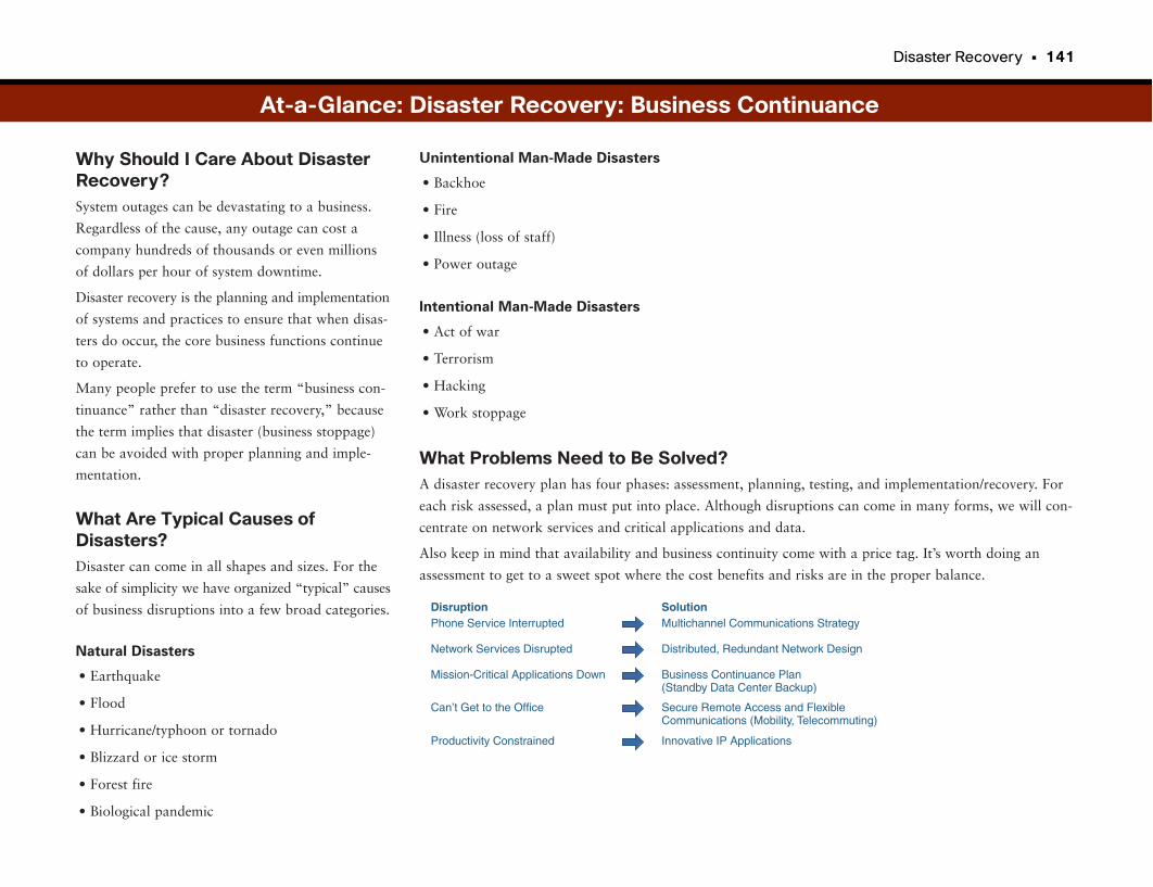
Disaster Recovery • 141
Why Should I Care About DisasterRecovery?System outages can be devastating to a business.
Regardless of the cause, any outage can cost a
company hundreds of thousands or even millions
of dollars per hour of system downtime.
Disaster recovery is the planning and implementation
of systems and practices to ensure that when disas-
ters do occur, the core business functions continue
to operate.
Many people prefer to use the term “business con-
tinuance” rather than “disaster recovery,” because
the term implies that disaster (business stoppage)
can be avoided with proper planning and imple-
mentation.
What Are Typical Causes ofDisasters?Disaster can come in all shapes and sizes. For the
sake of simplicity we have organized “typical” causes
of business disruptions into a few broad categories.
Natural Disasters
• Earthquake
• Flood
• Hurricane/typhoon or tornado
• Blizzard or ice storm
• Forest fire
• Biological pandemic
Unintentional Man-Made Disasters
• Backhoe
• Fire
• Illness (loss of staff)
• Power outage
Intentional Man-Made Disasters
• Act of war
• Terrorism
• Hacking
• Work stoppage
What Problems Need to Be Solved?A disaster recovery plan has four phases: assessment, planning, testing, and implementation/recovery. For
each risk assessed, a plan must put into place. Although disruptions can come in many forms, we will con-
centrate on network services and critical applications and data.
Also keep in mind that availability and business continuity come with a price tag. It’s worth doing an
assessment to get to a sweet spot where the cost benefits and risks are in the proper balance.
At-a-Glance: Disaster Recovery: Business Continuance
DisruptionPhone Service Interrupted
SolutionMultichannel Communications Strategy
Network Services Disrupted Distributed, Redundant Network Design
Productivity Constrained Innovative IP Applications
Mission-Critical Applications Down Business Continuance Plan(Standby Data Center Backup)
Can’t Get to the Office Secure Remote Access and FlexibleCommunications (Mobility, Telecommuting)
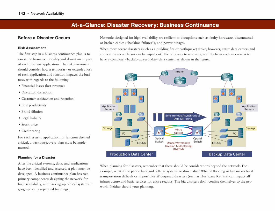
142 • Network Availability
Before a Disaster Occurs
Risk Assessment
The first step in a business continuance plan is to
assess the business criticality and downtime impact
of each business application. The risk assessment
should consider how a temporary or extended loss
of each application and function impacts the busi-
ness, with regards to the following:
• Financial losses (lost revenue)
• Operation disruption
• Customer satisfaction and retention
• Lost productivity
• Brand dilution
• Legal liability
• Stock price
• Credit rating
For each system, application, or function deemed
critical, a backup/recovery plan must be imple-
mented.
Planning for a Disaster
After the critical systems, data, and applications
have been identified and assessed, a plan must be
developed. A business continuance plan has two
primary components: designing the network for
high availability, and backing up critical systems in
geographically separated buildings.
Networks designed for high availability are resilient to disruptions such as faulty hardware, disconnected
or broken cables (“backhoe failures”), and power outages.
When more severe disasters (such as a building fire or earthquake) strike, however, entire data centers and
application server farms can be wiped out. The only way to recover gracefully from such an event is to
have a completely backed-up secondary data center, as shown in the figure.
At-a-Glance: Disaster Recovery: Business Continuance
Storage
FC
ESCON
ApplicationServers
Storage
FC
Dense WavelengthDivision Multiplexing
(DWDM)
ESCON
ApplicationServers
Synchronous/AsynchronousData Mirroring
Production Data Center Backup Data Center
MetroOptical
OpticalSwitch
OpticalSwitch
Intranet
When planning for disasters, remember that there should be considerations beyond the network. For
example, what if the phone lines and cellular systems go down also? What if flooding or fire makes local
transportation difficult or impossible? Widespread disasters (such as Hurricane Katrina) can impact all
infrastructure and basic services for entire regions. The big disasters don’t confine themselves to the net-
work. Neither should your planning.
Disaster Recovery • 143
Backing Up SystemsThere are a number of ways to back up data cen-
ters and application farms. Some companies back
up systems each night after the close of business. In
this case, the worst-case data loss is a single day.
Another backup scheme is called synchronous data
mirroring. It allows companies to perform real-
time backups with no lag, ensuring that virtually
no data is lost in the event of a natural or man-
made disaster. An added benefit of synchronous
data mirroring is that both systems can be online
at the same time, providing load and application
sharing, which can increase overall productivity.
The main challenge with synchronous data mirror-
ing is the potential significant slowing of applica-
tion performance. To achieve synchronous remote
mirroring without affecting application perform-
ance, high-speed, low-latency connections, such as
Dense Wavelength Division Multiplexing (DWDM)
over optical fiber, are preferred.
Such architectures for synchronous mirrored data
centers that are both active are sometimes called an
“active-active” model. For large companies, they
are a necessity. For smaller companies this might be
cost-prohibitive, so other methods of backup are
necessary.
3. Assess the likelihood of additional or second-
ary disasters. An earthquake, for example,
could spark fires or burst gas or water mains.
4. Monitor the network to ensure business
continuation.
Restoring Primary SystemsDepending on the severity of damage to, and the
duration of downtime for, primary systems, the
restoration of these systems may also disrupt
business.
Backing up data stored on the backup systems and
restoring the primary systems must be taken into
account.
Preparedness TestingOne of the best ways to ensure either a smooth
recovery from, or the complete avoidance of, a dis-
aster is to provide staff with real-world training
simulations. Allowing IT staff to practice different
disaster scenarios will greatly improve their ability
to cope with actual disasters.
Such “mock” disasters are common for training in
healthcare, emergency response, and law enforce-
ment agencies. They are just as effective for train-
ing corporate network staff.
After a Disaster Occurs
Recovery to Normal Operations
Practice and planning are put to the test if disaster
strikes. To avoid confusion, or worse (such as caus-
ing more damage), a checklist should be developed
as part of the planning effort and should be followed
when the time comes. The checklist will vary from
business to business and situation to situation, but
most will closely resemble the following example:
1. Make sure that your people are safe. Are all
personnel accounted for? Consider sending
home noncritical personnel to avoid confusion.
2. Check to make sure the backup systems are
online.
At-a-Glance: Disaster Recovery: Business Continuance
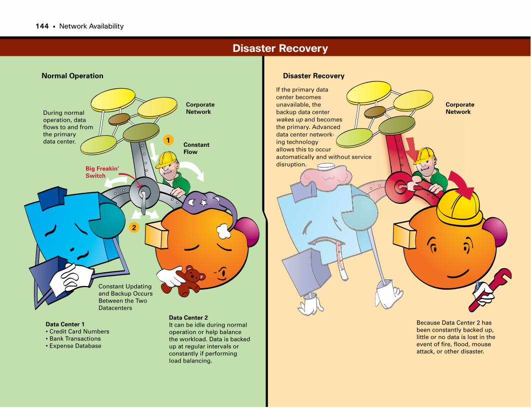
Corporate
Network
Corporate
Network
If the primary datacenter becomes unavailable, the backup data centerwakes up and becomesthe primary. Advanceddata center network-ing technologyallows this to occur automatically and without service disruption.
During normaloperation, data flows to and fromthe primary data center.
Data Center 2
It can be idle during normaloperation or help balancethe workload. Data is backedup at regular intervals orconstantly if performingload balancing.
Data Center 1
• Credit Card Numbers• Bank Transactions• Expense Database
Because Data Center 2 hasbeen constantly backed up,little or no data is lost in the event of fire, flood, mouseattack, or other disaster.
Disaster RecoveryNormal Operation
Constant
Flow
Constant Updatingand Backup OccursBetween the Two Datacenters
Big Freakin’
Switch
1
2
Disaster Recovery
144 • Network Availability

This page intentionally left blank
Network Management
Keeping the Network Alive from AfarNetwork management is the process of documenting, monitoring, trou-
bleshooting, and configuring network devices. Network management gives vis-
ibility to the networking staff. The routers and switches in a network have the
same components as a regular PC. There are a CPU (or two), memory, storage,
and network interfaces. The primary difference from a PC is that network
equipment is highly optimized to perform certain functions, such as passing
packets quickly. The nature of today’s networks is that network equipment is
distributed everywhere. Remote branches, data centers, locations around the
world—all these places on the network have routers, switches, servers, and
other networking gear.
Network administrators are responsible for the health and well-being of a
company’s network. Their goal generally is to provide uninterrupted network
services. If a network outage or fault occurs, they want to know about it as
soon as possible and isolate the problem quickly. When a problem occurs in
the network, it can bring business to a grinding halt.
The network administrators must find, isolate, and fix the fault as quickly as
possible to restore business operations. The longer the fault persists, depending
on the number of people and processes affected, the greater the monetary loss-
es the company might experience. For example, a manufacturing line might
stop operating. Or a stock-trading firm might stop trading. A hospital might
lose the ability to track patients. A theme park might be unable to collect tickets.
When a network fault occurs, a network administrator needs to gain visibility
to the network, taking into close consideration any changes that might have
occurred recently, to determine the source of the problem. Aside from dealing
with faults, network management facilitates the orderly upgrade or mainte-
nance of network devices. Remember, a company might have network devices
installed all over the world, so it is impractical for a network administrator to
physically travel to all the various locations to upgrade code.
Several process models can be adopted to form the basis of a network manage-
ment process framework, including FCAPS and ITIL.
FCAPS stands for Fault, Configuration, Accounting, Performance, and
Security. FCAPS represents the thinking about network operations going back
to the 1980s. In short, the areas of network operations and management under
FCAPS are broken down into these areas:
• Fault: Finding and correcting network problems.
• Configuration: Monitoring and controlling network devices and configuration.
• Accounting: Ensuring that devices are distributed appropriately and provid-
ing the ability to account (and bill) for usage.
• Performance: Measuring the throughput in the network and looking for
potential bottlenecks. This area is especially important when determining
capacity for applications and users.
• Security: Protecting the network from inadvertent mistakes and intentional
sabotage.
Another more recent network management process framework is the
Information Technology Infrastructure Library (ITIL). ITIL takes a more service-
oriented viewpoint, focusing on the end services provided by the network,
instead of the network itself. The key operational areas of ITIL are as follows:
• Service strategy identifies the IT services that could be developed as strategic
assets for use by internal or external customers of a business.
• Service design develops a service strategy into an IT service design that
addresses aspects of the proposed service, including availability, capacity,
continuity, and security.
• Service transition focuses on implementing and creating a production serv-
ice, including change management, release management, configuration man-
agement, and service knowledge management.
• Service operation focuses on the operations aspects to maintain services at
defined service levels, including problem management and incident manage-
ment.
• Continual service improvement is the ability to continually improve the
quality and service levels of the services the IT department delivers.
148 • Network Availability
FCAPS and ITIL have similarities. ITIL takes a broader perspective, looking at
the total lifecycle of network services. ITIL also takes a viewpoint of the serv-
ices the network is providing rather than the network itself.
Whether you employ FCAPS, ITIL, or another methodology to ensure network
availability, management, and operations, it’s important that you adopt and
use a methodology that meets the company’s goals.
The elements that make up an effective network-management strategy are
documentation, network-management protocols, and troubleshooting tools.
Network Documentation: A Must-HaveA relatively simple yet often overlooked process of network management is
documenting how all the network devices connect to each other. Network doc-
umentation becomes indispensable during network problems.
Documentation takes many forms:
• Logical network diagrams show how all the devices are connected.
• Cabling charts document where cable runs in a building. These charts are
vital when you want to figure out where the other end of a cable terminates.
(Is it an office or another floor?)
• A database correlates IP addresses and other network information with indi-
vidual users and locations.
• Where more than a couple of people are responsible for a network, you
need change-control documentation. Change control is the process of docu-
menting any changes to the network before you make them so that a group
can review the changes and ensure that one set of changes doesn’t overwrite
another.
• You can reference logs from network devices when you want to determine
the source of a problem.
Cisco devices send console messages and Simple Network Management
Protocol (SNMP) traps (discussed next) to a remote server for this purpose. By
studying the log of messages, a network administrator might be able to deter-
mine the source of a problem.
Network-Management ProtocolsMany tools and protocols help you effectively manage network devices. These
tools and protocols help you configure, back up, monitor, and measure net-
work devices. Network-management software makes efficient use of public
domain protocols to discover and manage networks. The first protocol is sim-
ply the Transmission Control Protocol/Internet Protocol (TCP/IP) ping tool.
Network-management software, in its simplest form, uses ping as a heartbeat
monitor. Ping sends a single request to a device, and the device is expected to
send back a single response when it receives the request. Thus, if your system
does not receive a response for a period of time (remember, packets might
drop in the network occasionally, so ping needs to retry three or more times),
you can assume that the device is unreachable for some reason.
An unreachable device indicates that somewhere between the network-
management workstation and the destination device, packets couldn’t pass.
Commercial network-management software indicates this fault by coloring a
graphical representation of a device red on a map of the network. (Green indi-
cates that everything is okay.) Whereas ping provides a heartbeat, SNMP lets
you get and set information between a network-management station and a
managed device such as a router or switch.
SNMP is a simple protocol that is similar to a database-retrieval program. The
managed device maintains a database of information such as the health of its
components (CPU, network interface, buffers) and throughput (how many
packets are passing through an interface). Using SNMP, a network administra-
tor can send a new configuration file to a device, upgrade its software, check
its health, and measure how many packets are flowing through the device.
You can store virtually anything about the device in the database in such a
way that a network-management workstation can learn about or configure
any aspect of the network device. SNMP also provides traps. Rather than a
command-and-response, like other SNMP commands, traps are unsolicited
responses. Managed devices, such as a router, send a trap when something
needs attention. For example, if an interface goes down, a router sends a trap,
notifying the network-management workstation. The workstation then indi-
cates that there is a fault on the device. Depending on the vendor, you might
use other protocols to manage a device.
Troubleshooting ToolsThe final component of network management is troubleshooting tools. These
tools help the network administrator isolate and correct a network problem
when it occurs.
These tools include cable testers, packet analyzers, and regular computers used
to query information on location. Cable testers and other physical-level devices
let you determine whether a cable has a physical problem. For example, a
cable might be too long and out of spec, or a device nearby might be causing
interference and disrupting the flow of traffic. Packet analyzers allow a net-
work administrator to monitor traffic on part of the network. The analyzer
not only captures the traffic, but also decodes the contents of each packet into
human-readable form. These tools are indispensable when you want to deter-
mine the source of a problem or an application’s behavior.
Because packet analyzers capture all traffic, a hacker can use the tool not only
to observe data as it flows through the network, but also to introduce lethal and
disruptive traffic into the network. The final tool is a regular laptop computer. A
network administrator can install network-management, packet-analyzer, and
database software and carry all the software tools he needs to troubleshoot
and correct a problem on location.
Network Management • 149
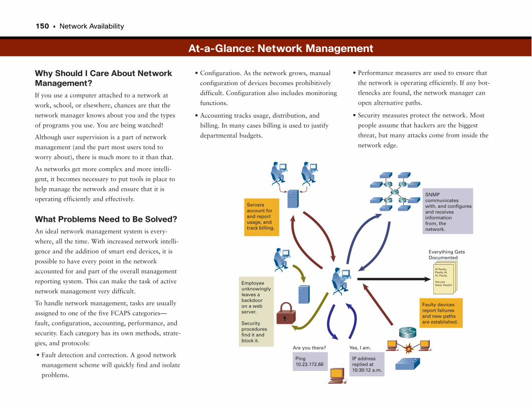
150 • Network Availability
Why Should I Care About NetworkManagement?If you use a computer attached to a network at
work, school, or elsewhere, chances are that the
network manager knows about you and the types
of programs you use. You are being watched!
Although user supervision is a part of network
management (and the part most users tend to
worry about), there is much more to it than that.
As networks get more complex and more intelli-
gent, it becomes necessary to put tools in place to
help manage the network and ensure that it is
operating efficiently and effectively.
What Problems Need to Be Solved?An ideal network management system is every-
where, all the time. With increased network intelli-
gence and the addition of smart end devices, it is
possible to have every point in the network
accounted for and part of the overall management
reporting system. This can make the task of active
network management very difficult.
To handle network management, tasks are usually
assigned to one of the five FCAPS categories—
fault, configuration, accounting, performance, and
security. Each category has its own methods, strate-
gies, and protocols:
• Fault detection and correction. A good network
management scheme will quickly find and isolate
problems.
• Configuration. As the network grows, manual
configuration of devices becomes prohibitively
difficult. Configuration also includes monitoring
functions.
• Accounting tracks usage, distribution, and
billing. In many cases billing is used to justify
departmental budgets.
At-a-Glance: Network Management
Serversaccount forand reportusage, andtrack billing.
SNMPcommunicateswith, and configuresand receivesinformationfrom, thenetwork.
Faulty devicesreport failuresand new pathsare established.
Employeeunknowinglyleaves abackdooron a webserver.
Securityproceduresfind it andblock it.
Ping10.23.172.66
Are you there?
IP addressreplied at10:30:12 a.m.
Yes, I am.
Everything GetsDocumented
Hi Paully.Paully, Hi.Hi. Paully.
Are youthere, Paully?
• Performance measures are used to ensure that
the network is operating efficiently. If any bot-
tlenecks are found, the network manager can
open alternative paths.
• Security measures protect the network. Most
people assume that hackers are the biggest
threat, but many attacks come from inside the
network edge.
Network Management • 151
Nightmare of MobilityKeeping track of thousands of devices was hard
enough for network managers when everything
basically stayed put. The huge surge in wireless
networking has added hundreds or thousands more
mobile devices, including laptops and PDAs, mak-
ing network managers’ jobs harder. Some strategies
for keeping track of mobile devices are in covered
in Part VIII, “Mobility.”
At-a-Glance: Network Management
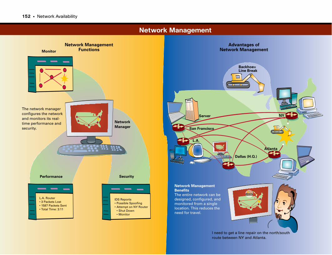
Network ManagementFunctions
Advantages of Network Management
Performance Security
Monitor
Network
Manager
The network managerconfigures the networkand monitors its real- time performance andsecurity.
L.A. Router• 3 Packets Lost• 1587 Packets Sent• Total Time: 3:11
IDS Reports• Possible Spoofing• Attempt on NY Router • Shut Down • Monitor
Server NY
Dallas (H.Q.)
L.A.
Network Management
Benefits
The entire network can be designed, configured, andmonitored from a singlelocation. This reduces the need for travel.
San Francisco
I need to get a line repair on the north/southroute between NY and Atlanta.
Backhoe=Line Break
Atlanta
Network Management
152 • Network Availability

This page intentionally left blank

Part V
Securing the NetworkThe sad truth is that almost as soon as there were networks, there was a need to secure them. In fact, the
need for security is so great that network security has become a multibillion-dollar-per-year industry.
This part begins with a primer on securing the network. Next we cover hacking and one of the earliest
strategies to mitigate hacker threats: firewalls.
It would be great if firewalls addressed all our security concerns, but the aggressive nature and sophistica-
tion of some network attacks require more sophisticated protection methods. The next topic covered is
intrusion detection, which helps network administrators deal with attacks that have penetrated the net-
work perimeter. We follow this with another mitigation method for insider attacks: port-based security.
We conclude the “insider” view of security with identity-based networking and Network Admission
Control. Identity-based networking is a method for making people prove they are who they say they are
before giving them access to the network. Network Admission Control is a method for preventing net-
work access until the device proves it has the proper security posture.
Sometimes it is important to ensure that your inside employees are conforming to company rules about
website access or file-sharing systems and downloads. The section “URL Filtering: Eliminating Unwanted
Web Page Access” looks at how this is accomplished. Finally, as a last defense, some companies will want
to inspect every packet that comes into the network just to be sure that they are free from malicious soft-
ware. “Deep Packet Inspection: Controlling Unwanted Applications” looks at how this is accomplished.
We also take a brief look at encryption, which protects data as it travels across the network. Another tool
in the security arsenal is telemetry, which is an advanced method of monitoring network activity to look
for anomalies that might indicate an active network attack.
Finally, we do not want to overlook one of the original methods of security—locking the doors. Part V
concludes with a look at physical security, focusing on integrating some traditional technologies such as
video surveillance with networking technologies.
Network Security 157
Firewalls 169
Intrusion Prevention Systems 177
Port-Based Security 181
Identity-Based Networking 187
Network Admission Control 193
URL Filtering: Eliminating 199
Unwanted Web Page Access
Deep Packet Inspection: 205+
Controlling Unwanted Applications
Telemetry: Identifying and 211
Isolating Attack Sources
Physical Security: 215
IP Video Surveillance
Network Security
A company’s network is like any other corporate asset: It is valuable, and it
affects the company’s success and revenue. More than ever, the corporate com-
puter network, and the data on it, is the most valuable asset of many companies.
Therefore, it must be protected. Generally, middle- to large-size companies
appoint a chief security officer, whose job is to develop and enforce corporate
security policies.
Security threats present themselves in many forms:
• A hacker breaking into the network to steal confidential information or
destroy corporate data
• A natural disaster such as a fire, tornado, or earthquake destroying comput-
er and network equipment
• A disgruntled employee intentionally trying to modify, steal, or destroy cor-
porate information and devices
• A computer virus or worm
• An act of war or terrorism
Common security threats introduced by people include the following:
• Network packet sniffers
• IP spoofing
• Password attacks
• Distribution of sensitive internal information to external sources
• Man-in-the-middle attacks
Internet security is also a big concern given the exposure of corporate data
resources to the publicly accessible Internet. Traditionally, you could achieve
security by physically separating corporate networks from public networks.
However, with corporate web servers and databases—and the desire to provide
access to corporate resources to employees over the Internet, or at overseas
locations—companies must be especially diligent at protecting their networks.
Another recent area of security concern is wireless networking. Traditional
networking occurred over physical wires or fibers. However, most companies
have installed wireless networking in their buildings so that employees can link
to the corporate network from conference rooms and other shared locations
from their laptop computers. Additionally, service providers now offer public
wireless Internet services.
The following sections describe the different categories of network security.
IdentityIdentity is the identification of network users, hosts, applications, services, and
resources. Examples of technologies that enable identification include 802.1x,
Remote Authentication Dial-In User Service (RADIUS), Kerberos, one-time
passwords, digital certificates, smart cards, biometrics, and directory services.
Perimeter SecurityPerimeter security controls access to critical network applications, data, and
services so that only legitimate users and information can access these assets.
Examples include access lists on routers and switches, firewalls, virus scanners,
and content filters. Perimeter security is particularly important where a busi-
ness network connects to a shared network, such as the Internet.
Data PrivacyThe ability to provide secure communication is crucial when you must protect
information from eavesdropping. Digital encryption technologies and proto-
cols such as Internet Protocol Security (IPsec), Secure Socket Layer (SSL), and
Secure Real-Time Protocol (SRTP) are commonly used to protect data, espe-
cially when being transported over a shared or untrusted network, such as a
service provider WAN or public Internet. New technologies such as Digital
Rights Management and “data watermarking” are also gaining traction. For
wireless networks, encryption and privacy protocols including Wired
Equivalent Privacy (WEP) and Wi-Fi Protected Access (WPA) provide similar
protections (discussed further in Part VIII, “Mobility”).
158 • Securing the Network
Security MonitoringRegardless of how security is implemented, it is still necessary to monitor a
network and its components to ensure that the network remains secure.
Network security monitoring tools and intrusion detection systems (IDS)
provide visibility into the network’s security status. State-of-the-art security
monitoring includes additional systems for anomaly detection and telemetry:
intelligently recognizing potential threats within the network and determining
their point of origin(s).
Policy EnforcementTools and technologies are worthless without well-defined security policies.
Effective policies balance the imposition of security measures against the pro-
ductivity gains realized with little security. Centralized policy-management
tools that can analyze, interpret, configure, and monitor the state of security
policies help consolidate the successful deployment of rational security poli-
cies. Complying with set policies offers another set of challenges. Functions
such as URL filtering can help enforce which places on the Internet employees
can reach and which are prohibited because they are out of policy.
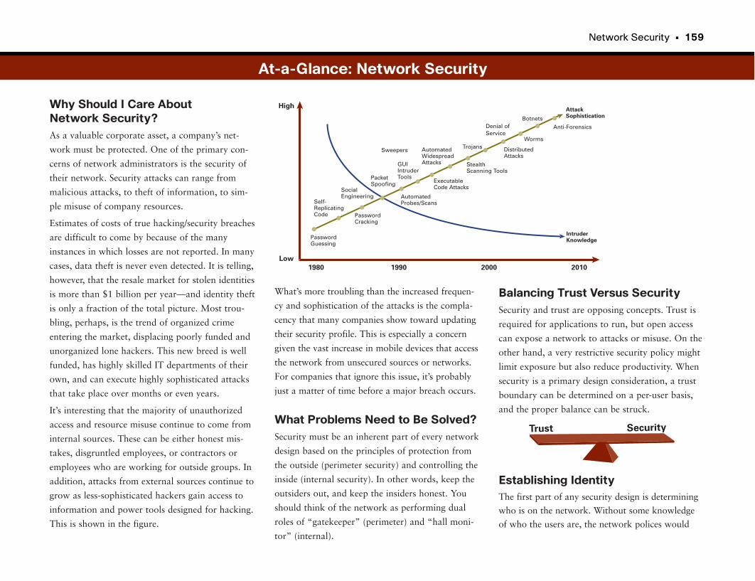
Network Security • 159
Why Should I Care About Network Security?As a valuable corporate asset, a company’s net-
work must be protected. One of the primary con-
cerns of network administrators is the security of
their network. Security attacks can range from
malicious attacks, to theft of information, to sim-
ple misuse of company resources.
Estimates of costs of true hacking/security breaches
are difficult to come by because of the many
instances in which losses are not reported. In many
cases, data theft is never even detected. It is telling,
however, that the resale market for stolen identities
is more than $1 billion per year—and identity theft
is only a fraction of the total picture. Most trou-
bling, perhaps, is the trend of organized crime
entering the market, displacing poorly funded and
unorganized lone hackers. This new breed is well
funded, has highly skilled IT departments of their
own, and can execute highly sophisticated attacks
that take place over months or even years.
It’s interesting that the majority of unauthorized
access and resource misuse continue to come from
internal sources. These can be either honest mis-
takes, disgruntled employees, or contractors or
employees who are working for outside groups. In
addition, attacks from external sources continue to
grow as less-sophisticated hackers gain access to
information and power tools designed for hacking.
This is shown in the figure.
Balancing Trust Versus SecuritySecurity and trust are opposing concepts. Trust is
required for applications to run, but open access
can expose a network to attacks or misuse. On the
other hand, a very restrictive security policy might
limit exposure but also reduce productivity. When
security is a primary design consideration, a trust
boundary can be determined on a per-user basis,
and the proper balance can be struck.
Establishing IdentityThe first part of any security design is determining
who is on the network. Without some knowledge
of who the users are, the network polices would
What’s more troubling than the increased frequen-
cy and sophistication of the attacks is the compla-
cency that many companies show toward updating
their security profile. This is especially a concern
given the vast increase in mobile devices that access
the network from unsecured sources or networks.
For companies that ignore this issue, it’s probably
just a matter of time before a major breach occurs.
What Problems Need to Be Solved?Security must be an inherent part of every network
design based on the principles of protection from
the outside (perimeter security) and controlling the
inside (internal security). In other words, keep the
outsiders out, and keep the insiders honest. You
should think of the network as performing dual
roles of “gatekeeper” (perimeter) and “hall moni-
tor” (internal).
Low
High
Self-ReplicatingCode
PasswordGuessing
PasswordCracking
SocialEngineering
Sweepers
PacketSpoofing
GUIIntruderTools
AutomatedWidespreadAttacks
BotnetsDenial ofService
Trojans
AutomatedProbes/Scans
ExecutableCode Attacks
StealthScanning Tools
DistributedAttacks
Worms
Anti-Forensics
AttackSophistication
IntruderKnowledge
1980 1990 2000 2010
At-a-Glance: Network Security
Trust Security
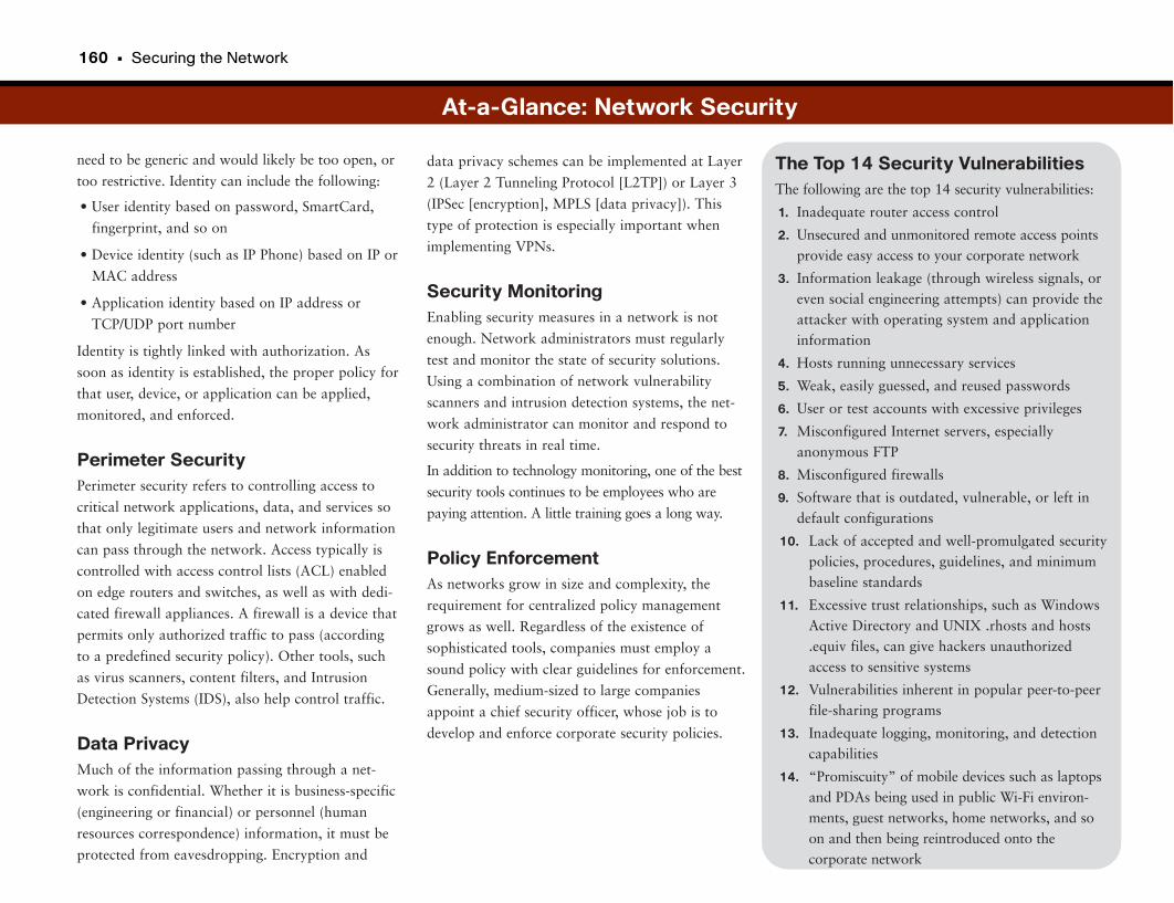
160 • Securing the Network
need to be generic and would likely be too open, or
too restrictive. Identity can include the following:
• User identity based on password, SmartCard,
fingerprint, and so on
• Device identity (such as IP Phone) based on IP or
MAC address
• Application identity based on IP address or
TCP/UDP port number
Identity is tightly linked with authorization. As
soon as identity is established, the proper policy for
that user, device, or application can be applied,
monitored, and enforced.
Perimeter SecurityPerimeter security refers to controlling access to
critical network applications, data, and services so
that only legitimate users and network information
can pass through the network. Access typically is
controlled with access control lists (ACL) enabled
on edge routers and switches, as well as with dedi-
cated firewall appliances. A firewall is a device that
permits only authorized traffic to pass (according
to a predefined security policy). Other tools, such
as virus scanners, content filters, and Intrusion
Detection Systems (IDS), also help control traffic.
Data PrivacyMuch of the information passing through a net-
work is confidential. Whether it is business-specific
(engineering or financial) or personnel (human
resources correspondence) information, it must be
protected from eavesdropping. Encryption and
The Top 14 Security VulnerabilitiesThe following are the top 14 security vulnerabilities:
1. Inadequate router access control
2. Unsecured and unmonitored remote access pointsprovide easy access to your corporate network
3. Information leakage (through wireless signals, oreven social engineering attempts) can provide theattacker with operating system and applicationinformation
4. Hosts running unnecessary services
5. Weak, easily guessed, and reused passwords
6. User or test accounts with excessive privileges
7. Misconfigured Internet servers, especially anonymous FTP
8. Misconfigured firewalls
9. Software that is outdated, vulnerable, or left indefault configurations
10. Lack of accepted and well-promulgated securitypolicies, procedures, guidelines, and minimumbaseline standards
11. Excessive trust relationships, such as WindowsActive Directory and UNIX .rhosts and hosts.equiv files, can give hackers unauthorizedaccess to sensitive systems
12. Vulnerabilities inherent in popular peer-to-peerfile-sharing programs
13. Inadequate logging, monitoring, and detectioncapabilities
14. “Promiscuity” of mobile devices such as laptopsand PDAs being used in public Wi-Fi environ-ments, guest networks, home networks, and soon and then being reintroduced onto the corporate network
data privacy schemes can be implemented at Layer
2 (Layer 2 Tunneling Protocol [L2TP]) or Layer 3
(IPSec [encryption], MPLS [data privacy]). This
type of protection is especially important when
implementing VPNs.
Security MonitoringEnabling security measures in a network is not
enough. Network administrators must regularly
test and monitor the state of security solutions.
Using a combination of network vulnerability
scanners and intrusion detection systems, the net-
work administrator can monitor and respond to
security threats in real time.
In addition to technology monitoring, one of the best
security tools continues to be employees who are
paying attention. A little training goes a long way.
Policy EnforcementAs networks grow in size and complexity, the
requirement for centralized policy management
grows as well. Regardless of the existence of
sophisticated tools, companies must employ a
sound policy with clear guidelines for enforcement.
Generally, medium-sized to large companies
appoint a chief security officer, whose job is to
develop and enforce corporate security policies.
At-a-Glance: Network Security
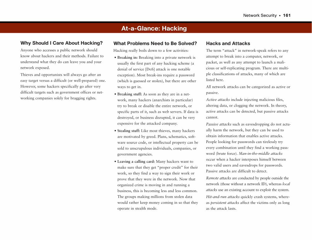
Network Security • 161
Why Should I Care About Hacking?Anyone who accesses a public network should
know about hackers and their methods. Failure to
understand what they do can leave you and your
network exposed.
Thieves and opportunists will always go after an
easy target versus a difficult (or well-prepared) one.
However, some hackers specifically go after very
difficult targets such as government offices or net-
working companies solely for bragging rights.
Hacks and AttacksThe term “attack” in network-speak refers to any
attempt to break into a computer, network, or
packet, as well as any attempt to launch a mali-
cious or self-replicating program. There are multi-
ple classifications of attacks, many of which are
listed here.
All network attacks can be categorized as active or
passive.
Active attacks include injecting malicious files,
altering data, or clogging the network. In theory,
active attacks can be detected, but passive attacks
cannot.
Passive attacks such as eavesdropping do not actu-
ally harm the network, but they can be used to
obtain information that enables active attacks.
People looking for passwords can tirelessly try
every combination until they find a working pass-
word (brute force). Man-in-the-middle attacks
occur when a hacker interposes himself between
two valid users and eavesdrops for passwords.
Passive attacks are difficult to detect.
Remote attacks are conducted by people outside the
network (those without a network ID), whereas local
attacks use an existing account to exploit the system.
Hit-and-run attacks quickly crash systems, where-
as persistent attacks affect the victims only as long
as the attack lasts.
What Problems Need to Be Solved?Hacking really boils down to a few activities:
• Breaking in: Breaking into a private network is
usually the first part of any hacking scheme (a
denial of service [DoS] attack is one notable
exception). Most break-ins require a password
(which is guessed or stolen), but there are other
ways to get in.
• Breaking stuff: As soon as they are in a net-
work, many hackers (anarchists in particular)
try to break or disable the entire network, or
specific parts of it, such as web servers. If data is
destroyed, or business disrupted, it can be very
expensive for the attacked company.
• Stealing stuff: Like most thieves, many hackers
are motivated by greed. Plans, schematics, soft-
ware source code, or intellectual property can be
sold to unscrupulous individuals, companies, or
government agencies.
• Leaving a calling card: Many hackers want to
make sure that they get “proper credit” for their
work, so they find a way to sign their work or
prove that they were in the network. Now that
organized crime is moving in and running a
business, this is becoming less and less common.
The groups making millions from stolen data
would rather keep money coming in so that they
operate in stealth mode.
At-a-Glance: Hacking
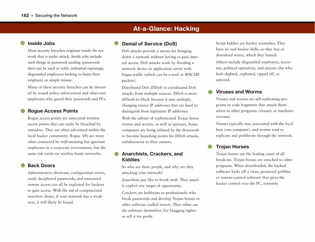
162 • Securing the Network
Inside JobsMost security breaches originate inside the net-
work that is under attack. Inside jobs include
such things as password stealing (passwords
then can be used or sold), industrial espionage,
disgruntled employees looking to harm their
employer, or simple misuse.
Many of these security breaches can be thwart-
ed by sound policy enforcement and observant
employees who guard their passwords and PCs.
Rogue Access PointsRogue access points are unsecured wireless
access points that can easily be breached by
outsiders. They are often advertised within the
local hacker community. Rogue APs are most
often connected by well-meaning but ignorant
employees in a corporate environment, but the
same risk exists on wireless home networks.
Back DoorsAdministrative shortcuts, configuration errors,
easily deciphered passwords, and unsecured
remote access can all be exploited for hackers
to gain access. With the aid of computerized
searchers (bots), if your network has a weak-
ness, it will likely be found.
Script kiddies are hacker wannabes. They
have no real hacker skills, so they buy or
download warez, which they launch.
Others include disgruntled employees, terror-
ists, political operatives, and anyone else who
feels slighted, exploited, ripped off, or
unloved.
Viruses and WormsViruses and worms are self-replicating pro-
grams or code fragments that attach them-
selves to other programs (viruses) or machines
(worms).
Viruses typically stay associated with the local
host (one computer), and worms tend to
replicate and proliferate through the network.
Trojan HorsesTrojan horses are the leading cause of all
break-ins. Trojan horses are attached to other
programs. When downloaded, the hacked
software kicks off a virus, password gobbler,
or remote-control software that gives the
hacker control over the PC, remotely.
Denial of Service (DoS)DoS attacks provide a means for bringing
down a network without having to gain inter-
nal access. DoS attacks work by flooding a
network device or application server with
bogus traffic (which can be e-mail or IP/ICMP
packets).
Distributed DoS (DDoS) is coordinated DoS
attacks from multiple sources. DDoS is more
difficult to block because it uses multiple,
changing source IP addresses that are hard to
distinguish from legitimate IP addresses.
With the advent of sophisticated Trojan horse
viruses and worms, as well as spyware, home
computers are being enlisted by the thousands
to become launching points for DDoS attacks,
unbeknownst to their owners.
Anarchists, Crackers, andKiddiesSo who are these people, and why are they
attacking your network?
Anarchists just like to break stuff. They usual-
ly exploit any target of opportunity.
Crackers are hobbyists or professionals who
break passwords and develop Trojan horses or
other software (called warez). They either use
the software themselves (for bragging rights)
or sell it for profit.
At-a-Glance: Hacking
1
2
3
4
5
6
7
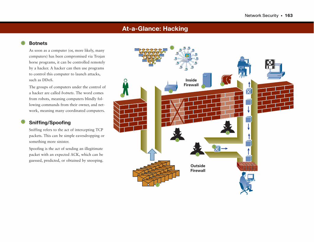
Network Security • 163
BotnetsAs soon as a computer (or, more likely, many
computers) has been compromised via Trojan
horse programs, it can be controlled remotely
by a hacker. A hacker can then use programs
to control this computer to launch attacks,
such as DDoS.
The groups of computers under the control of
a hacker are called botnets. The word comes
from robots, meaning computers blindly fol-
lowing commands from their owner, and net-
work, meaning many coordinated computers.
Sniffing/SpoofingSniffing refers to the act of intercepting TCP
packets. This can be simple eavesdropping or
something more sinister.
Spoofing is the act of sending an illegitimate
packet with an expected ACK, which can be
guessed, predicted, or obtained by snooping.
DoS AttacksSnooping and Spoofing
Inside
Firewall
Outside
Firewall
7
12
3
4
5
5
6
8
9
At-a-Glance: Hacking
8
9
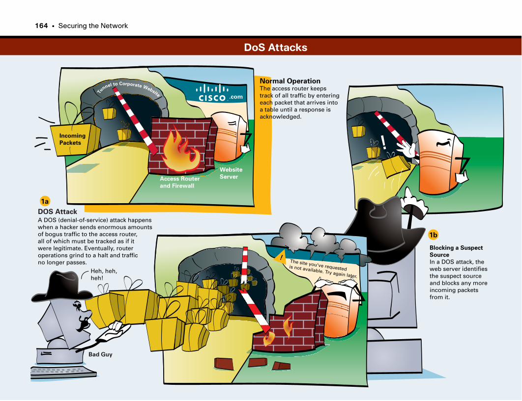
!
Tunnel to Corporate Website
.com
Incoming
Packets
Heh, heh, heh!
DOS Attack
The site you've requestedis not available. Try again later.
!
A DOS (denial-of-service) attack happenswhen a hacker sends enormous amountsof bogus traffic to the access router, all of which must be tracked as if it were legitimate. Eventually, router operations grind to a halt and traffic no longer passes.
Website
ServerAccess Router
and Firewall
Bad Guy
Normal OperationThe access router keeps track of all traffic by enteringeach packet that arrives intoa table until a response is acknowledged.
1a
1b
Blocking a Suspect
Source
In a DOS attack, the web server identifiesthe suspect source and blocks any more incoming packets from it.
DoS Attacks
164 • Securing the Network
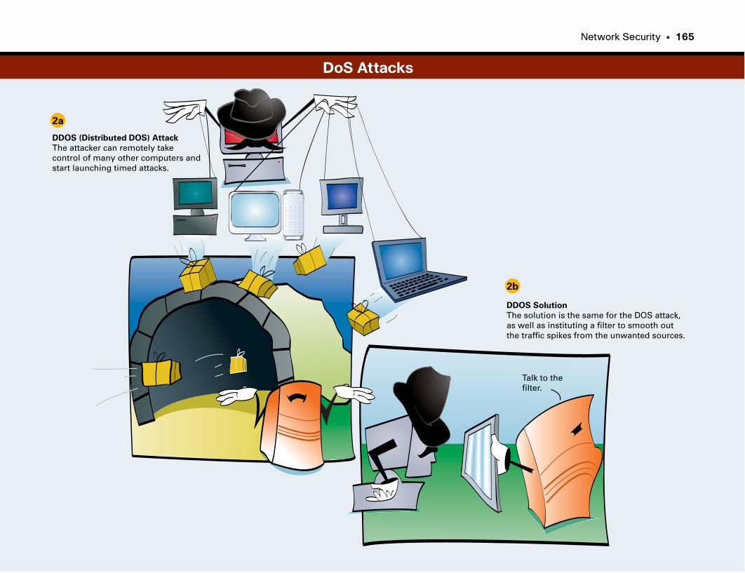
Network Security • 165
2a
2b
DDOS (Distributed DOS) Attack
The attacker can remotely takecontrol of many other computers andstart launching timed attacks.
DDOS Solution
The solution is the same for the DOS attack, as well as instituting a filter to smooth out the traffic spikes from the unwanted sources.
Talk to thefilter.
DoS Attacks
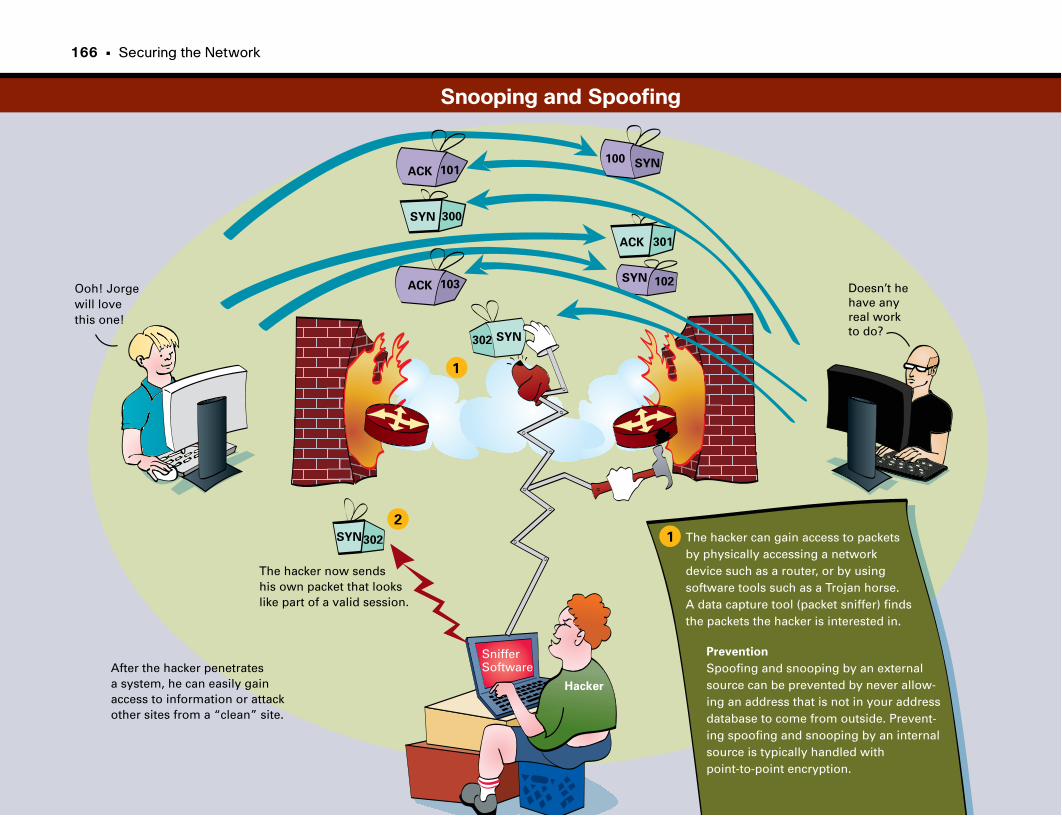
The hacker now sendshis own packet that lookslike part of a valid session.
After the hacker penetratesa system, he can easily gainaccess to information or attackother sites from a “clean” site.
Ooh! Jorge will love this one!
302
103
300
SYN
SYN
SYN
SYN
ACK
ACK
302
102
301
SnifferSoftware
Prevention
Spoofing and snooping by an externalsource can be prevented by never allow-ing an address that is not in your address database to come from outside. Prevent-ing spoofing and snooping by an internalsource is typically handled with point-to-point encryption.
The hacker can gain access to packetsby physically accessing a networkdevice such as a router, or by usingsoftware tools such as a Trojan horse. A data capture tool (packet sniffer) findsthe packets the hacker is interested in.
Hacker
Doesn’t hehave anyreal workto do?
1
1
2
101ACKSYN100
Snooping and Spoofing
166 • Securing the Network

This page intentionally left blank
Firewalls
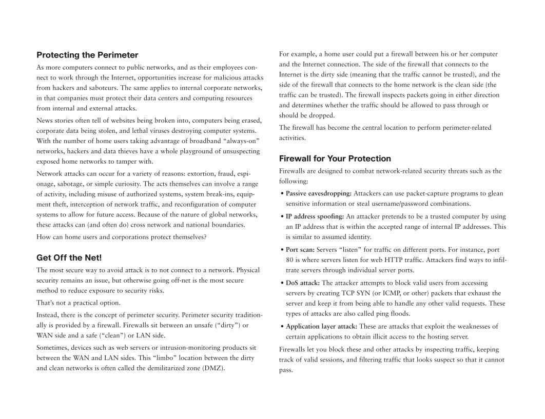
Protecting the PerimeterAs more computers connect to public networks, and as their employees con-
nect to work through the Internet, opportunities increase for malicious attacks
from hackers and saboteurs. The same applies to internal corporate networks,
in that companies must protect their data centers and computing resources
from internal and external attacks.
News stories often tell of websites being broken into, computers being erased,
corporate data being stolen, and lethal viruses destroying computer systems.
With the number of home users taking advantage of broadband “always-on”
networks, hackers and data thieves have a whole playground of unsuspecting
exposed home networks to tamper with.
Network attacks can occur for a variety of reasons: extortion, fraud, espi-
onage, sabotage, or simple curiosity. The acts themselves can involve a range
of activity, including misuse of authorized systems, system break-ins, equip-
ment theft, interception of network traffic, and reconfiguration of computer
systems to allow for future access. Because of the nature of global networks,
these attacks can (and often do) cross network and national boundaries.
How can home users and corporations protect themselves?
Get Off the Net!The most secure way to avoid attack is to not connect to a network. Physical
security remains an issue, but otherwise going off-net is the most secure
method to reduce exposure to security risks.
That’s not a practical option.
Instead, there is the concept of perimeter security. Perimeter security tradition-
ally is provided by a firewall. Firewalls sit between an unsafe (“dirty”) or
WAN side and a safe (“clean”) or LAN side.
Sometimes, devices such as web servers or intrusion-monitoring products sit
between the WAN and LAN sides. This “limbo” location between the dirty
and clean networks is often called the demilitarized zone (DMZ).
For example, a home user could put a firewall between his or her computer
and the Internet connection. The side of the firewall that connects to the
Internet is the dirty side (meaning that the traffic cannot be trusted), and the
side of the firewall that connects to the home network is the clean side (the
traffic can be trusted). The firewall inspects packets going in either direction
and determines whether the traffic should be allowed to pass through or
should be dropped.
The firewall has become the central location to perform perimeter-related
activities.
Firewall for Your ProtectionFirewalls are designed to combat network-related security threats such as the
following:
• Passive eavesdropping: Attackers can use packet-capture programs to glean
sensitive information or steal username/password combinations.
• IP address spoofing: An attacker pretends to be a trusted computer by using
an IP address that is within the accepted range of internal IP addresses. This
is similar to assumed identity.
• Port scan: Servers “listen” for traffic on different ports. For instance, port
80 is where servers listen for web HTTP traffic. Attackers find ways to infil-
trate servers through individual server ports.
• DoS attack: The attacker attempts to block valid users from accessing
servers by creating TCP SYN (or ICMP, or other) packets that exhaust the
server and keep it from being able to handle any other valid requests. These
types of attacks are also called ping floods.
• Application layer attack: These are attacks that exploit the weaknesses of
certain applications to obtain illicit access to the hosting server.
Firewalls let you block these and other attacks by inspecting traffic, keeping
track of valid sessions, and filtering traffic that looks suspect so that it cannot
pass.
170 • Securing the Network
Personal FirewallsAnother type of firewall that has become common is the personal firewall.
Typically this is a software program on a laptop or computer that acts as a
firewall. Its function is slightly different than the firewalls just described.
Personal firewalls typically guard a computer or laptop against unauthorized
installation of programs, such as a malicious program or spyware installing
itself on your computer, commonly without the user’s knowledge.
Another function of the personal firewall is to monitor programs on the com-
puter that are trying to access the Internet, enabling the user to allow or deny
access program by program. In this way, malicious programs seeking to access
the Internet, either to propagate themselves or to report information back to
the creator, can be blocked from doing so.
To learn more about this topic, pick up a copy of Home Network Security
Simplified (Cisco Press, 2006).
Firewalls • 171
Why Should I Care About Firewalls and IDS?Firewalls and Intrusion Detection Systems (IDS) pro-
vide perimeter defense for corporate and personal
networks. As hackers have become more sophisticat-
ed (and aggressive) in their attacks, so has the tech-
nology behind keeping networks safe. Firewalls and
IDS were created as a direct response to hackers.
In addition to pure technology advances, a great
deal of innovation has occurred concerning how to
deploy these systems. This topic is of special
importance to companies with websites.
What Problems Need to Be Solved?The main goal of perimeter security is to keep the
bad guys out of the network. The only way to be
absolutely sure about perimeter security is to not
connect to anything. Most companies rely on the
Internet, though, and for some it is a critical aspect
of their business. The problem to be solved, then,
is how to have an external presence and still be rel-
atively safe against attacks.
The answer is the three-part firewall system, which
places external-facing servers in an intermediate
zone (DMZ) in the network between two separate
firewalls.
What Does a Firewall Do?Firewalls keep both corporate and personal net-
works safe from attack by inspecting packets for
Clean NetThe clean net is the interior corporate network.
The only “outside” packets permitted on the clean
net are those that have been inspected and have
the acknowledgment to a TCP packet generated
from an inside computer.
Inside FilterThe inside filter performs the functions of both a
firewall and intrusion detection system. In addition
to blocking attacks such as DoS, it inspects every
packet, making sure that no externally initiated
TCP sessions reach the clean net, because hackers
can gain access by spoofing a session. Any packets
of questionable origin get trashed. The inside filter
also inspects outbound packets to ensure compli-
ance with corporate policies.
Isolation LANThe isolation LAN or DMZ acts as a buffer
between outside- (web) facing applications and the
clean LAN. Servers located in the DMZ are called
bastion hosts. Outsiders use them to access public
web pages or FTP servers. These servers are pro-
tected but are still prone to hackers. Bastion hosts
should have as few services as possible and should
contain very simple access rules to prevent back
doors into the clean LAN.
known attack profiles and by acting as a proxy
between you and the rest of the world.
Profiles (such as virus signatures or rules for pack-
et contents) are usually discovered and maintained
by service companies that sell the profile packages
for a fee.
The proxy function works by using a third IP
address (as opposed to the user’s actual source IP
address or that of the server) whenever you com-
municate with the world. That way, no one knows
your actual IP address.
Are You a Good Packet or a BadPacket?In terms of a firewall system, good packets fall
into two categories:
Good outbound packets are sent by inside
users to approved external locations, such
as a website.
Good inbound packets originate outside the
external firewall. They either correspond to
a TCP session originated by an inside user
(that is, they can only be response packets)
or are accessing publicly available services
such as web traffic.
Bad packets are pretty much everything else
(unsolicited packets that are not sent in
response to a request from inside). They are
discarded for the safety of the network.
At-a-Glance: Firewalls and IDS
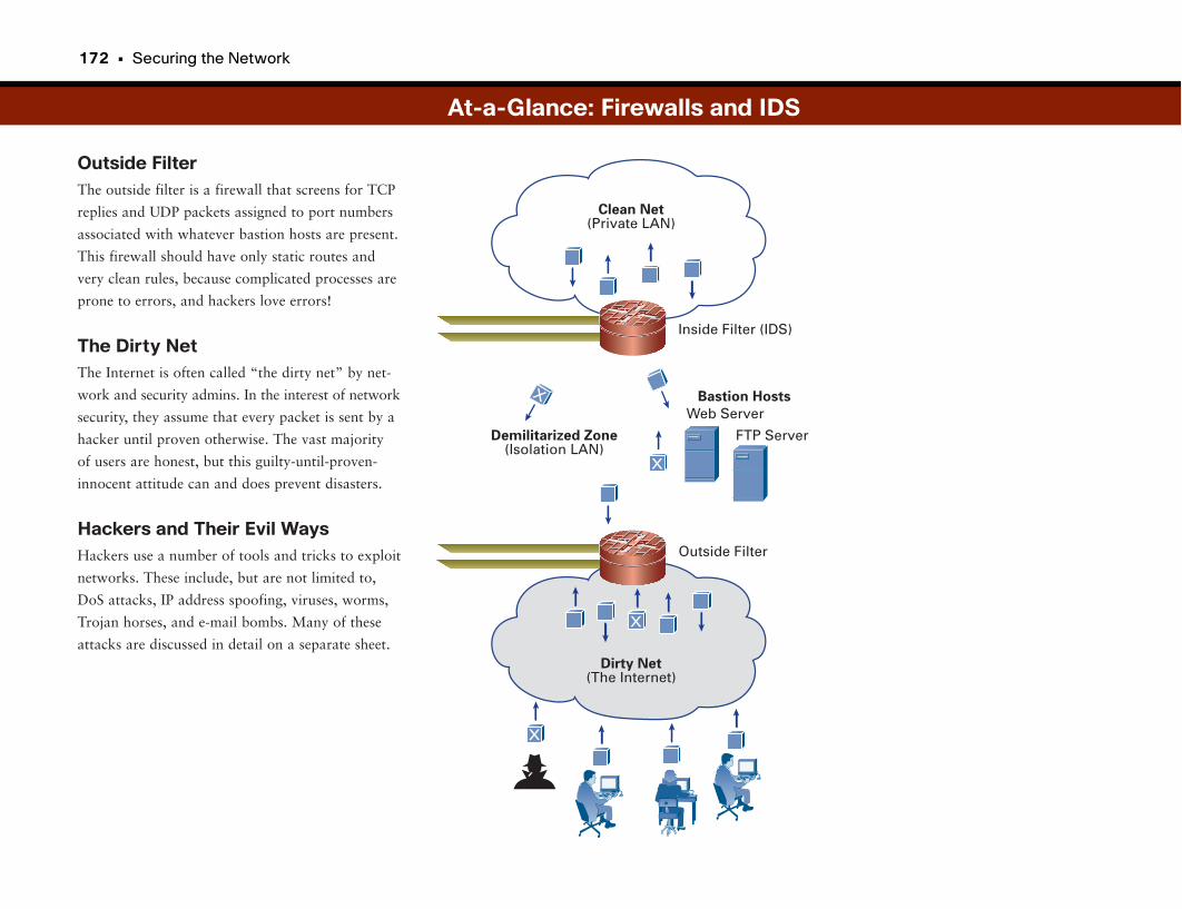
172 • Securing the Network
Outside FilterThe outside filter is a firewall that screens for TCP
replies and UDP packets assigned to port numbers
associated with whatever bastion hosts are present.
This firewall should have only static routes and
very clean rules, because complicated processes are
prone to errors, and hackers love errors!
The Dirty NetThe Internet is often called “the dirty net” by net-
work and security admins. In the interest of network
security, they assume that every packet is sent by a
hacker until proven otherwise. The vast majority
of users are honest, but this guilty-until-proven-
innocent attitude can and does prevent disasters.
Hackers and Their Evil WaysHackers use a number of tools and tricks to exploit
networks. These include, but are not limited to,
DoS attacks, IP address spoofing, viruses, worms,
Trojan horses, and e-mail bombs. Many of these
attacks are discussed in detail on a separate sheet.
At-a-Glance: Firewalls and IDS
Clean Net(Private LAN)
Inside Filter (IDS)
Web ServerBastion Hosts
Outside Filter
Demilitarized Zone(Isolation LAN)
Dirty Net(The Internet)
FTP Server
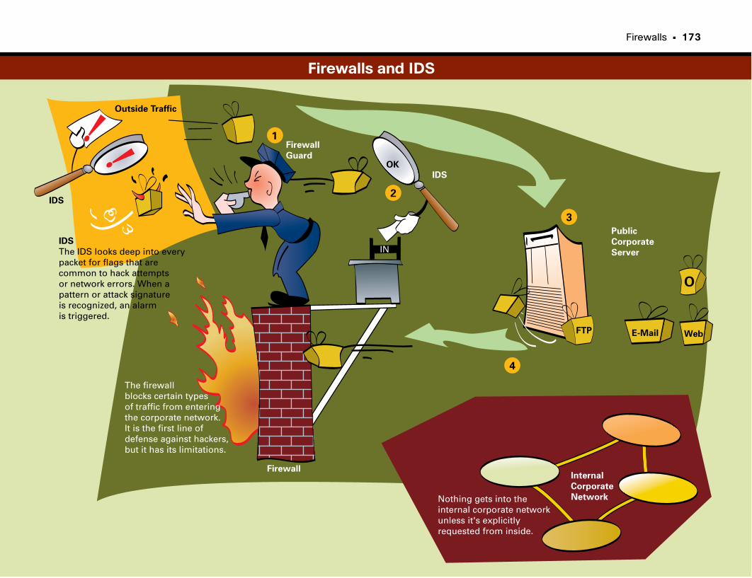
Firewalls • 173
O
Outside Traffic
IDS
IDS
The IDS looks deep into everypacket for flags that arecommon to hack attemptsor network errors. When apattern or attack signatureis recognized, an alarmis triggered.
The firewall blocks certain types of traffic from enteringthe corporate network.It is the first line of defense against hackers, but it has its limitations.
Firewall
OK
IN
Nothing gets into theinternal corporate networkunless it's explicitly requested from inside.
Internal
Corporate
Network
Public
Corporate
Server
FTP E-Mail Web
IDS
1
2
3
4
Firewall
Guard
Firewalls and IDS
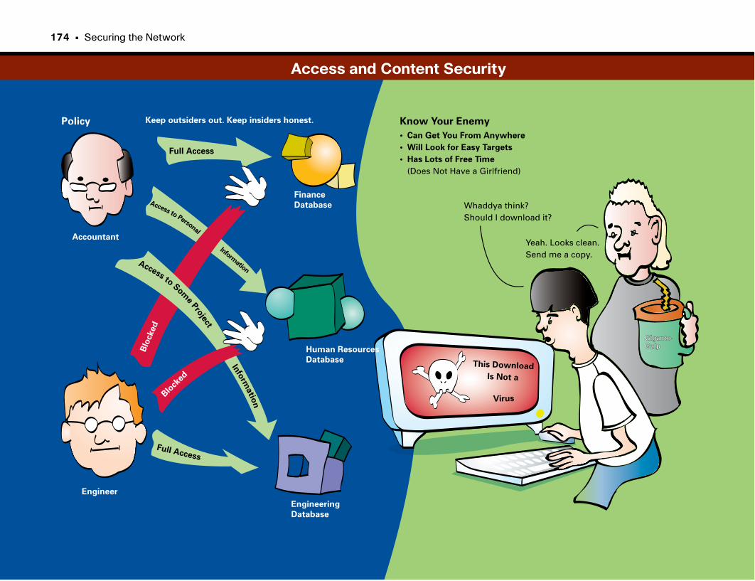
Policy Know Your Enemy
• Can Get You From Anywhere
• Will Look for Easy Targets
• Has Lots of Free Time
(Does Not Have a Girlfriend)
Keep outsiders out. Keep insiders honest.
Full Access
Full Access
Blo
cked
Blo
cked
Accountant
Engineer
Finance
Database
Human Resources
Database
Engineering
Database
Access to Personal
Information
Access toSom
ePro
ject
Info
rmatio
n
Whaddya think?Should I download it?
Yeah. Looks clean.Send me a copy.
This Download
Is Not a
Virus
Giganto-Giganto-
GulpGulp
Access and Content Security
174 • Securing the Network

This page intentionally left blank
Intrusion Prevention Systems
Intrusion Detection SystemsFirewalls provide a barrier for traffic. However, some traffic may look legiti-
mate and may in fact be legitimate, but it might be carrying devious viruses or
attack programs.
Although a firewall is sufficient for home use, corporations tend to have more
at risk and choose to invest in extra measures to detect traffic patterns that a
firewall can’t catch. Intrusion detection provides this ability.
IDSs analyze data in real time to detect, log, and hinder misuse and attacks.
Host-based IDSs monitor server operations for any mischievous events.
Network-based IDSs monitor network traffic on a specific portion of the
network.
Network-based IDSs monitor traffic in real time, looking at a set of packets
for known attack signatures. When it detects a particular suspicious data flow,
the IDS logs the finding. It then can tell the receiving router to deny the traffic
and any future traffic from the source.
Intrusion Prevention SystemsSimilar to IDS is the concept of Intrusion Prevention Systems (IPS). Both IDS
and IPS require a database of known attack signatures to be programmed into
the IDS or IPS network device. However, whereas an IDS typically detects
intrusion attempts and logs them or sends alerts to network staff, IPS typically
operates “inline” within the network and includes additional measures to halt
intrusion attempts in real time.
Although it might seem as though these technologies do the same thing and
maybe even replace firewalls, keep in mind that each technology provides an
additional layer of security. This approach, called “defense in depth,” provides
a multilayered approach to security, ensuring that a breach of one system does
not put the entire network at risk.
The Problem with False PositivesOne of the largest challenges with IDS or IPS is distinguishing real attacks
from false positives. These are legitimate traffic that sets off an alarm in an
IDS/IPS sensor because some of the traffic pattern matches an attack signature.
It’s a bit like your neighbor’s car alarm going off. If it goes off ten times a
week, you start to ignore it, and if the car really gets stolen, no one notices. It
is important to tune IDS/IPS implementations to reduce the occurrence of false
positives to as close to zero as possible. That way, when a network administra-
tor or information security officer is notified of an intrusion, it is meaningful.
178 • Securing the Network
Why Should I Care About IntrusionDetection?Businesses and homes are connected to the Internet
using an always-on connection, providing targets
for electronic intruders and hackers. Network
intrusions and attacks cost businesses money in
terms of information theft, productivity losses from
compromised services, and remediation costs for
compromised hosts. Despite an added focus on net-
work security, intrusions are growing more fre-
quent and more sophisticated. Only automated
intrusion detection and prevention solutions can
mitigate complex attacks with the speed required
or prevent real damage or runaway costs.
What Problems Need to Be Solved?To be effective, intrusion detection solutions must
be active at all entry points to the network, includ-
ing the following:
• From the Internet
• From branch offices and small offices/home offices
• From inside the company
The system must also provide protection of net-
work assets and services provided by the network,
such as servers.
On important aspect of intrusion detection is the
ability to operate as a passive detection system,
logging potential intrusion events, or as an active
prevention system, taking mitigating actions in real
and mitigation. IDS/IPS sensors can be deployed as
router-based (IOS-IPS), host-based (Cisco Security
Agent, CSA), or as appliances in the network.
Events from all types of sensors are reported to a
central event correlation and management system
so that network administrators can monitor intru-
sion events and take action.
time. Intrusion detection must also be able to cor-
relate multiple events over a window of time to
detect complex attacks.
Where Can IDS Be Deployed?Cisco Intrusion Prevention System (CIPS) provides
a network-wide approach to intrusion detection
At-a-Glance: Intrusion Detection
DMZ
Internet
InsideNetwork
ManagementConsole
IDS inNetwork
IDS/IPS inHome Office
IDS/IPSBranchRouter
Telecommuter
IPS inPerimeter
IDS inDMZ
Host IDSon Servers
MonitoringConsole
ManagementNetwork
Branch/Regional Offices
Intrusion Prevention Systems • 179
Passive MonitoringAn IDS passively monitors packets on the network
and logs events. The figure shows the steps
involved:
1. Traffic on the network is copied and routed to
the IDS Sensor for analysis.
2. If traffic matches an intrusion signature, the sig-
nature “fires.”
3. IDS Sensor sends an alarm to the management
console.
With IDS, packets that are part of the intrusion
attempt can still reach the target.
Active MonitoringAn IPS actively monitors packets inline on the net-
work. The figure shows the steps involved:
1. Traffic on the network is not copied but is for-
warded through the IPS Sensor for analysis.
2. If traffic matches an intrusion signature, the sig-
nature “fires.”
3. Traffic that matches the signature is dropped.
4. IPS Sensor also sends an alarm to the manage-
ment console.
With IPS, packets that are part of the intrusion
attempt are prevented from reaching the target.
Sneak AttacksSophisticated attacks may involve multiple events
(which in this case refers to several packets or
sequences of packets) over a period of time.
Discrete events can make it difficult to detect an
attack. CIPS can correlate multiple events over a
time window to recognize a sophisticated attack
vector, such as an Internet worm.
Switch
Target
Sensor
ManagementSystem
1
2
3
At-a-Glance: Intrusion Detection
WORM X
Meta Reset Interval = 20 Seconds
Signature 5081cmd.exe Access
Signature 5124IIS CGI Decode
Signature 5114IIS Unicode Attack
Signature 3215Dot Dot Execute
Signature 3216Dot Dot Crash
Target
Sensor
ManagementSystem
1
2
3
4
Port-Based Security
Combating Access-Based AttacksA common entry point for network threats are the wired (and wireless) access
ports where devices connect, such as laptops, printers, IP phones, and others.
Without appropriate measures, hackers attempting to cause mischief in net-
works can plug into a port and use it as a launching location to work their
way into the rest of the network. Such intrusions may require physical access
to the corporate location. Physical security measures such as locked doors,
badge readers, video surveillance, and security staff are always a critical line of
defense to prevent such attacks.
However, gaining physical access to many corporate locations is not as hard as
you might think. A practice known as tailgating is one of the most common
means to gain entry. Tailgating occurs when an employee of a company swipes
her ID badge through a badge reader to unlock an exterior door, and the
intruder follows her through the door.
Tailgating can be passive, meaning that the employee may not even notice that
the person behind her grabbed the door before it closed. Tailgating also can be
active, meaning that the employee out of courtesy actually holds the door
open. One very effective tailgating scheme involves the malicious individual
approaching the door with an armload of stuff. The employee helpfully opens
the door (social engineering makes this possible).
Video surveillance can help prevent such trespassing. But you must train
employees to watch for tailgaters. Employees must be willing to challenge indi-
viduals who don’t display corporate credentials.
Physical access is not necessarily required. A virus, worm, or Trojan horse pro-
gram can be placed on a laptop that an employee carries inside the business
and plugs into the network. A company’s wireless connectivity can extend into
nearby buildings or parking lots, removing the need for an intruder to enter
the company.
Whether a person gains access physically or by using stealth, as soon as he is
“inside,” he can slip into the nearest empty cubicle or conference room, plug
in, and start his attack. A number of measures need to work in concert to
totally prevent such maliciousness:
• Port-based security
• Identity-based networking
• Network Admission Control (NAC)
• Wireless network security
The first three topics are discussed in the following sections. Wireless network
security is discussed further in Part VIII, “Mobility.”
Port-based security involves taking a number of precautions on each wired
network access port. Doing so prevents several known types of malicious
entry:
• MAC flooding
• Malicious Dynamic Host Configuration Protocol (DHCP) server
• ARP poisoning
• IP address spoofing
Locking down network access ports eliminates one point of entry for hacking
and intrusion. Access to the network may still be possible, but several tools
commonly used for malicious intrusion into the network are effectively taken
out of the hacker’s toolbox.
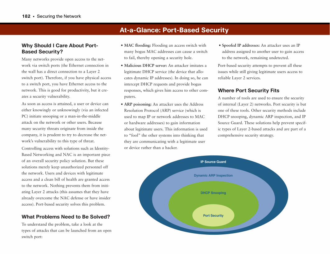
182 • Securing the Network
Why Should I Care About Port-Based Security?Many networks provide open access to the net-
work via switch ports (the Ethernet connection in
the wall has a direct connection to a Layer 2
switch port). Therefore, if you have physical access
to a switch port, you have Ethernet access to the
network. This is good for productivity, but it cre-
ates a security vulnerability.
As soon as access is attained, a user or device can
either knowingly or unknowingly (via an infected
PC) initiate snooping or a man-in-the-middle
attack on the network or other users. Because
many security threats originate from inside the
company, it is prudent to try to decrease the net-
work’s vulnerability to this type of threat.
Controlling access with solutions such as Identity-
Based Networking and NAC is an important piece
of an overall security policy solution. But these
solutions merely keep unauthorized personnel off
the network. Users and devices with legitimate
access and a clean bill of health are granted access
to the network. Nothing prevents them from initi-
ating Layer 2 attacks (this assumes that they have
already overcome the NAC defense or have insider
access). Port-based security solves this problem.
What Problems Need to Be Solved?To understand the problem, take a look at the
types of attacks that can be launched from an open
switch port:
• Spoofed IP addresses: An attacker uses an IP
address assigned to another user to gain access
to the network, remaining undetected.
Port-based security attempts to prevent all these
issues while still giving legitimate users access to
reliable Layer 2 services.
Where Port Security FitsA number of tools are used to ensure the security
of internal (Layer 2) networks. Port security is but
one of these tools. Other security methods include
DHCP snooping, dynamic ARP inspection, and IP
Source Guard. These solutions help prevent specif-
ic types of Layer 2-based attacks and are part of a
comprehensive security strategy.
• MAC flooding: Flooding an access switch with
many bogus MAC addresses can cause a switch
to fail, thereby opening a security hole.
• Malicious DHCP server: An attacker imitates a
legitimate DHCP service (the device that allo-
cates dynamic IP addresses). In doing so, he can
intercept DHCP requests and provide bogus
responses, which gives him access to other com-
puters.
• ARP poisoning: An attacker uses the Address
Resolution Protocol (ARP) service (which is
used to map IP or network addresses to MAC
or hardware addresses) to gain information
about legitimate users. This information is used
to “fool” the other systems into thinking that
they are communicating with a legitimate user
or device rather than a hacker.
At-a-Glance: Port-Based Security
IP Source Guard
Dynamic ARP Inspection
DHCP Snooping
Port Security
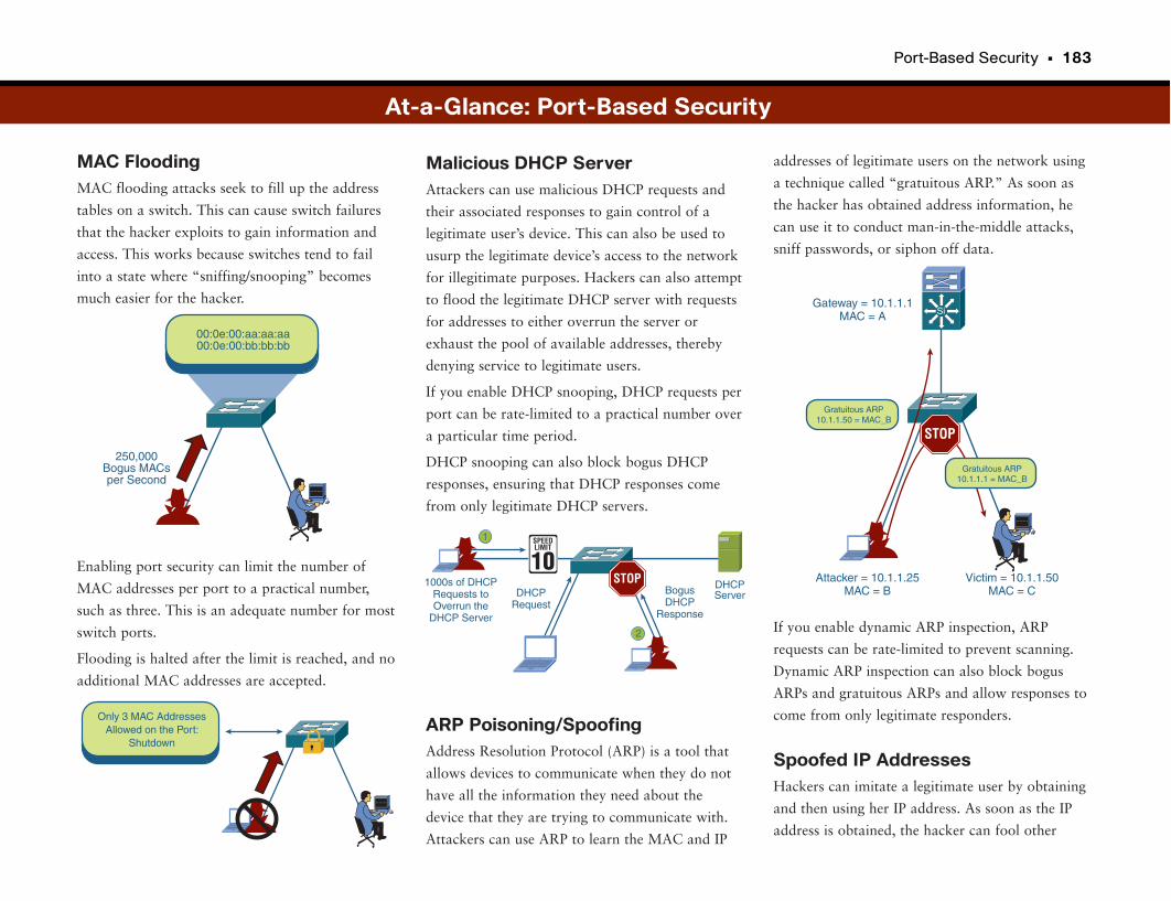
Port-Based Security • 183
MAC FloodingMAC flooding attacks seek to fill up the address
tables on a switch. This can cause switch failures
that the hacker exploits to gain information and
access. This works because switches tend to fail
into a state where “sniffing/snooping” becomes
much easier for the hacker.
Enabling port security can limit the number of
MAC addresses per port to a practical number,
such as three. This is an adequate number for most
switch ports.
Flooding is halted after the limit is reached, and no
additional MAC addresses are accepted.
addresses of legitimate users on the network using
a technique called “gratuitous ARP.” As soon as
the hacker has obtained address information, he
can use it to conduct man-in-the-middle attacks,
sniff passwords, or siphon off data.
If you enable dynamic ARP inspection, ARP
requests can be rate-limited to prevent scanning.
Dynamic ARP inspection can also block bogus
ARPs and gratuitous ARPs and allow responses to
come from only legitimate responders.
Spoofed IP AddressesHackers can imitate a legitimate user by obtaining
and then using her IP address. As soon as the IP
address is obtained, the hacker can fool other
Malicious DHCP ServerAttackers can use malicious DHCP requests and
their associated responses to gain control of a
legitimate user’s device. This can also be used to
usurp the legitimate device’s access to the network
for illegitimate purposes. Hackers can also attempt
to flood the legitimate DHCP server with requests
for addresses to either overrun the server or
exhaust the pool of available addresses, thereby
denying service to legitimate users.
If you enable DHCP snooping, DHCP requests per
port can be rate-limited to a practical number over
a particular time period.
DHCP snooping can also block bogus DHCP
responses, ensuring that DHCP responses come
from only legitimate DHCP servers.
ARP Poisoning/SpoofingAddress Resolution Protocol (ARP) is a tool that
allows devices to communicate when they do not
have all the information they need about the
device that they are trying to communicate with.
Attackers can use ARP to learn the MAC and IP
Gateway = 10.1.1.1MAC = A
Attacker = 10.1.1.25MAC = B
Victim = 10.1.1.50MAC = C
STOP
Gratuitous ARP10.1.1.50 = MAC_B
Gratuitous ARP10.1.1.1 = MAC_B
Si
At-a-Glance: Port-Based Security
1000s of DHCPRequests toOverrun the
DHCP Server
DHCPRequest
BogusDHCP
Response
DHCPServer
1
2
STOP10SPEEDLIMIT
00:0e:00:aa:aa:aa00:0e:00:bb:bb:bb
250,000Bogus MACsper Second
Only 3 MAC AddressesAllowed on the Port:
Shutdown
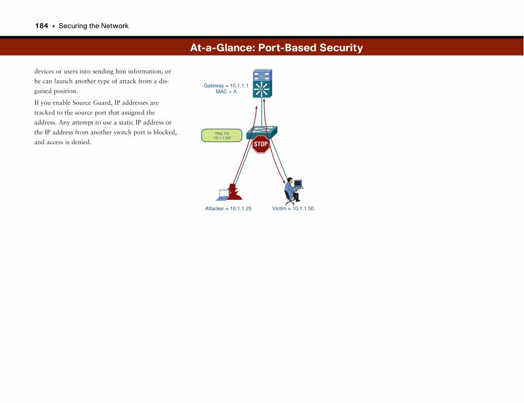
184 • Securing the Network
devices or users into sending him information, or
he can launch another type of attack from a dis-
guised position.
If you enable Source Guard, IP addresses are
tracked to the source port that assigned the
address. Any attempt to use a static IP address or
the IP address from another switch port is blocked,
and access is denied.
At-a-Glance: Port-Based Security
Gateway = 10.1.1.1MAC = A
Attacker = 10.1.1.25 Victim = 10.1.1.50
STOP
Hey, I’m10.1.1.50!
Si

This page intentionally left blank

Identity-Based Networking
Network Access ConundrumLegacy networks typically operated under a model of allowing devices to be
plugged into the network. As long as they could understand and communicate
the basic protocols of OSI Layer 1 (physical layer) and Layer 2 (data link
layer), they could get access to the network. The ease of plugging in and getting
a “hot” Ethernet connection helped fuel the widespread adoption of networks
and speeded the decline of other, more complex methods of connectivity.
Ease of use and security measures are often at odds with each other. The more
restrictive network access policies are, often the more difficult it is for network
users to jump through the right hoops to be granted access. Such is the
quandary for providing network access. Too restrictive means that less-
experienced legitimate users may have their network access inadvertently
denied. Not restrictive enough means that unauthorized users may easily get
on the network, possibly as easily as employees.
Identity-Based NetworkingMost modern corporate networks do not provide access to network services to
a device or user without first establishing the device’s or user’s entitlement to
those services. Identity-Based Networking Services (IBNS) lets network admin-
istrators restrict access to devices that can prove their “identity” to the network.
Identity may involve different types of credentials for different devices. For
example, a laptop or computer may require the user to enter his or her corpo-
rate user ID and password. Other devices that cannot necessarily respond to a
password prompt, such as printers or Network Attached Storage (NAS)
devices, may rely on other forms of authentication, such as the device’s MAC
address or a preloaded digital certificate.
In either case, IBNS operates at the edge of the network on access ports. When
a device is plugged into the network, Layers 1 and 2 are established, but
before access to the network is permitted, the access switch challenges the
device to provide its identity credentials. The credentials provided by the
device are passed through the network to authentication servers in the data
center and are validated. Validated devices are granted access, and unautho-
rized devices are prevented from sending traffic to the network.
IBNS dramatically changes the network access model from one of starting with
an easily accessible “hot” Ethernet port, requiring only physical access to plug
into it, to a model of devices needing to be preauthorized to have even the
basic form of network access. Access to a “hot” Ethernet connection is contin-
gent upon the device’s proving that it is part of the set of devices that are with-
in the corporate device “family.”
802.1xThe network protocol commonly used for IBNS is standardized in the IEEE
standard known as 802.1x. 802.1x establishes the communication paths neces-
sary between the device seeking network access and the access switch provid-
ing the authentication challenge. All modern OS clients (Windows, Mac,
Linux) support 802.1x.
802.1x has also been at the core of corporate wireless network security almost
since the inception of wireless networks, providing a critical part of wireless
security. Similar to wired, the wireless form of 802.1x requires devices to pres-
ent credentials to gain access to the wireless network. Unauthenticated devices
are refused access.
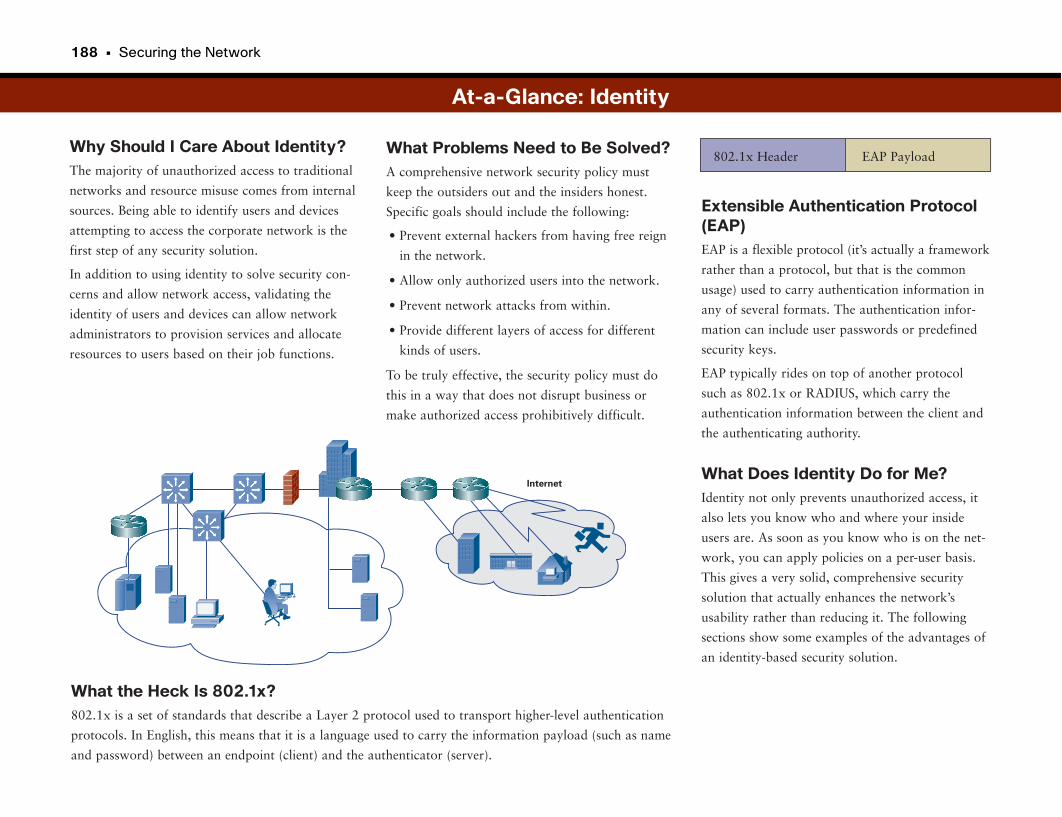
188 • Securing the Network
Why Should I Care About Identity?The majority of unauthorized access to traditional
networks and resource misuse comes from internal
sources. Being able to identify users and devices
attempting to access the corporate network is the
first step of any security solution.
In addition to using identity to solve security con-
cerns and allow network access, validating the
identity of users and devices can allow network
administrators to provision services and allocate
resources to users based on their job functions.
Extensible Authentication Protocol(EAP)EAP is a flexible protocol (it’s actually a framework
rather than a protocol, but that is the common
usage) used to carry authentication information in
any of several formats. The authentication infor-
mation can include user passwords or predefined
security keys.
EAP typically rides on top of another protocol
such as 802.1x or RADIUS, which carry the
authentication information between the client and
the authenticating authority.
What Does Identity Do for Me?Identity not only prevents unauthorized access, it
also lets you know who and where your inside
users are. As soon as you know who is on the net-
work, you can apply policies on a per-user basis.
This gives a very solid, comprehensive security
solution that actually enhances the network’s
usability rather than reducing it. The following
sections show some examples of the advantages of
an identity-based security solution.
What Problems Need to Be Solved?A comprehensive network security policy must
keep the outsiders out and the insiders honest.
Specific goals should include the following:
• Prevent external hackers from having free reign
in the network.
• Allow only authorized users into the network.
• Prevent network attacks from within.
• Provide different layers of access for different
kinds of users.
To be truly effective, the security policy must do
this in a way that does not disrupt business or
make authorized access prohibitively difficult.
At-a-Glance: Identity
802.1x Header EAP Payload
What the Heck Is 802.1x?802.1x is a set of standards that describe a Layer 2 protocol used to transport higher-level authentication
protocols. In English, this means that it is a language used to carry the information payload (such as name
and password) between an endpoint (client) and the authenticator (server).
Internet
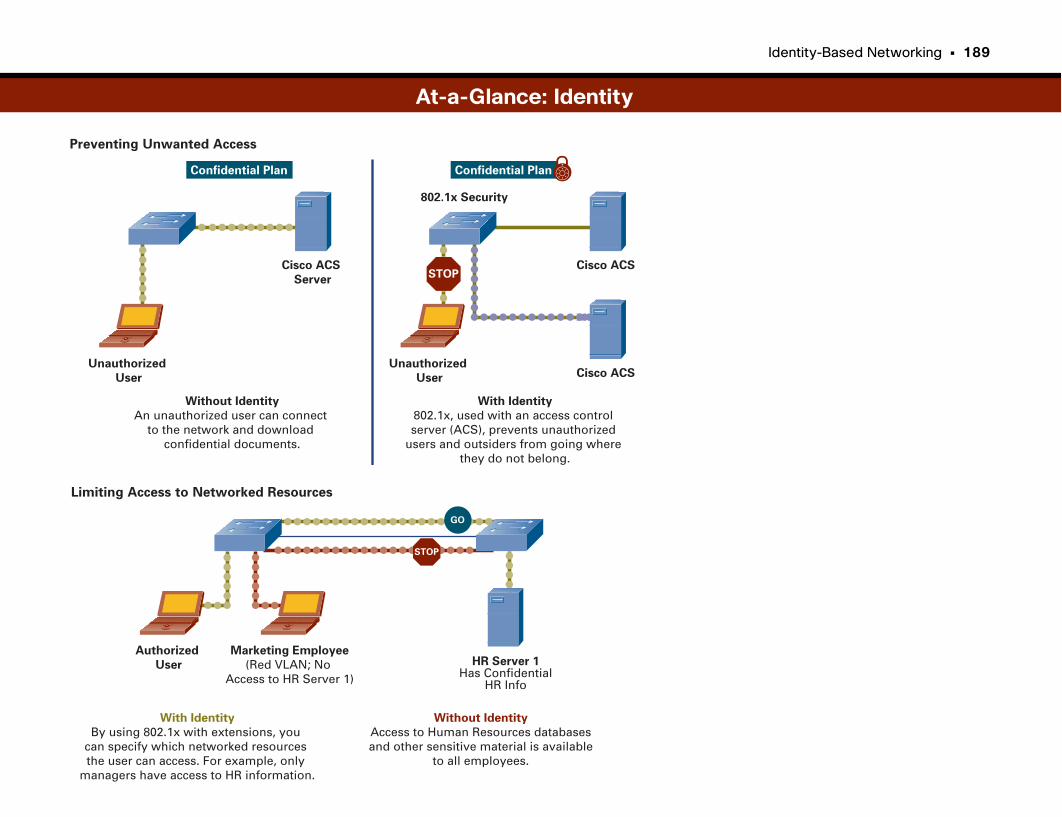
Identity-Based Networking • 189
Preventing Unwanted Access
Limiting Access to Networked Resources
At-a-Glance: Identity
Cisco ACS
Server
Unauthorized
User
802.1x Security
Without Identity
An unauthorized user can connectto the network and download
confidential documents.
With Identity
802.1x, used with an access controlserver (ACS), prevents unauthorized
users and outsiders from going where they do not belong.
Confidential Plan
Cisco ACS
Unauthorized
User
Confidential Plan
Cisco ACS
STOP
Authorized
User
Without Identity
Access to Human Resources databasesand other sensitive material is available
to all employees.
With Identity
By using 802.1x with extensions, you can specify which networked resources the user can access. For example, only
managers have access to HR information.
Marketing Employee
(Red VLAN; No Access to HR Server 1)
HR Server 1Has Confidential
HR Info
STOP
GO
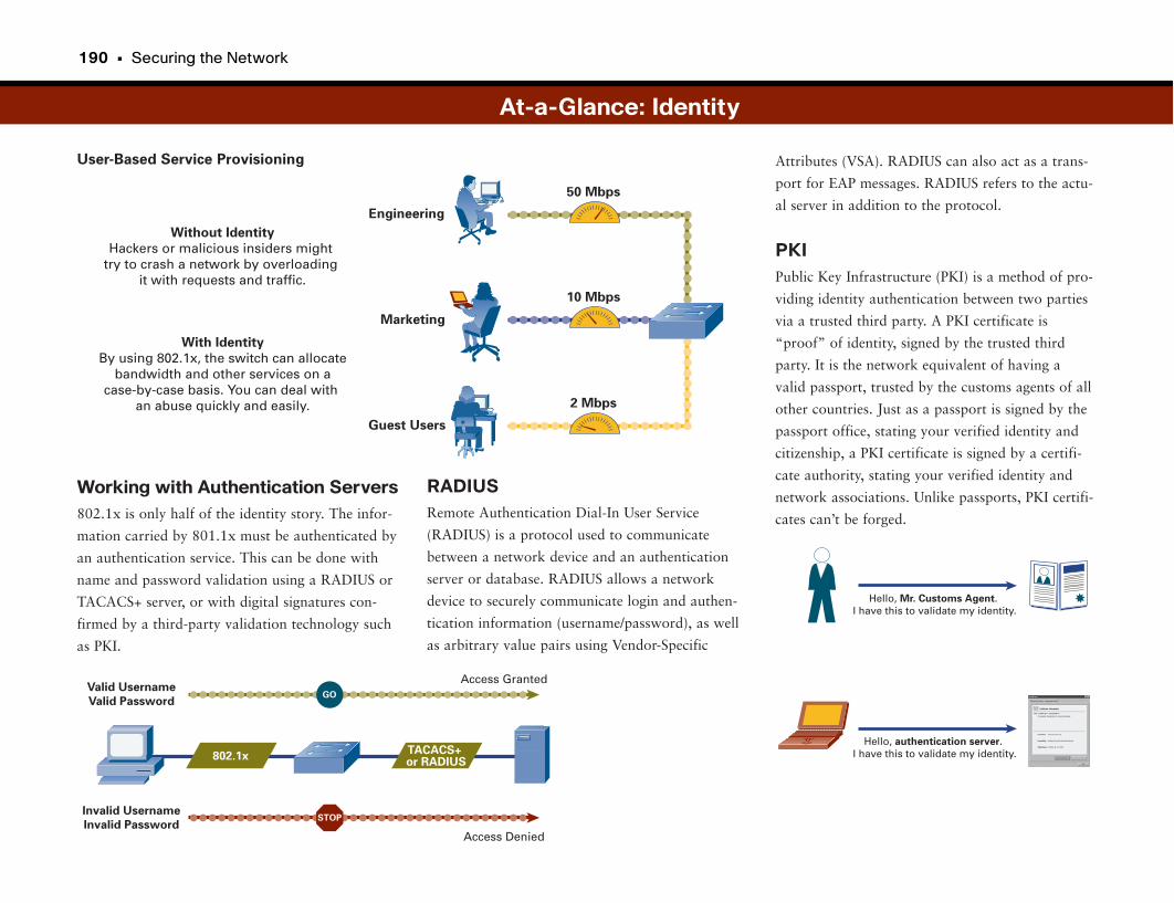
190 • Securing the Network
User-Based Service Provisioning
Working with Authentication Servers802.1x is only half of the identity story. The infor-
mation carried by 801.1x must be authenticated by
an authentication service. This can be done with
name and password validation using a RADIUS or
TACACS+ server, or with digital signatures con-
firmed by a third-party validation technology such
as PKI.
Attributes (VSA). RADIUS can also act as a trans-
port for EAP messages. RADIUS refers to the actu-
al server in addition to the protocol.
PKIPublic Key Infrastructure (PKI) is a method of pro-
viding identity authentication between two parties
via a trusted third party. A PKI certificate is
“proof” of identity, signed by the trusted third
party. It is the network equivalent of having a
valid passport, trusted by the customs agents of all
other countries. Just as a passport is signed by the
passport office, stating your verified identity and
citizenship, a PKI certificate is signed by a certifi-
cate authority, stating your verified identity and
network associations. Unlike passports, PKI certifi-
cates can’t be forged.
RADIUSRemote Authentication Dial-In User Service
(RADIUS) is a protocol used to communicate
between a network device and an authentication
server or database. RADIUS allows a network
device to securely communicate login and authen-
tication information (username/password), as well
as arbitrary value pairs using Vendor-Specific
At-a-Glance: Identity
Marketing
50 Mbps
Guest Users
Engineering
Without Identity
Hackers or malicious insiders might try to crash a network by overloading
it with requests and traffic.
With Identity
By using 802.1x, the switch can allocatebandwidth and other services on a
case-by-case basis. You can deal with an abuse quickly and easily.
10 Mbps
2 Mbps
Invalid Username
Invalid Password
Access Granted
Access Denied
Valid Username
Valid Password
STOP
GO
802.1xTACACS+ or RADIUS
Hello, Mr. Customs Agent.I have this to validate my identity.
Hello, authentication server.I have this to validate my identity.
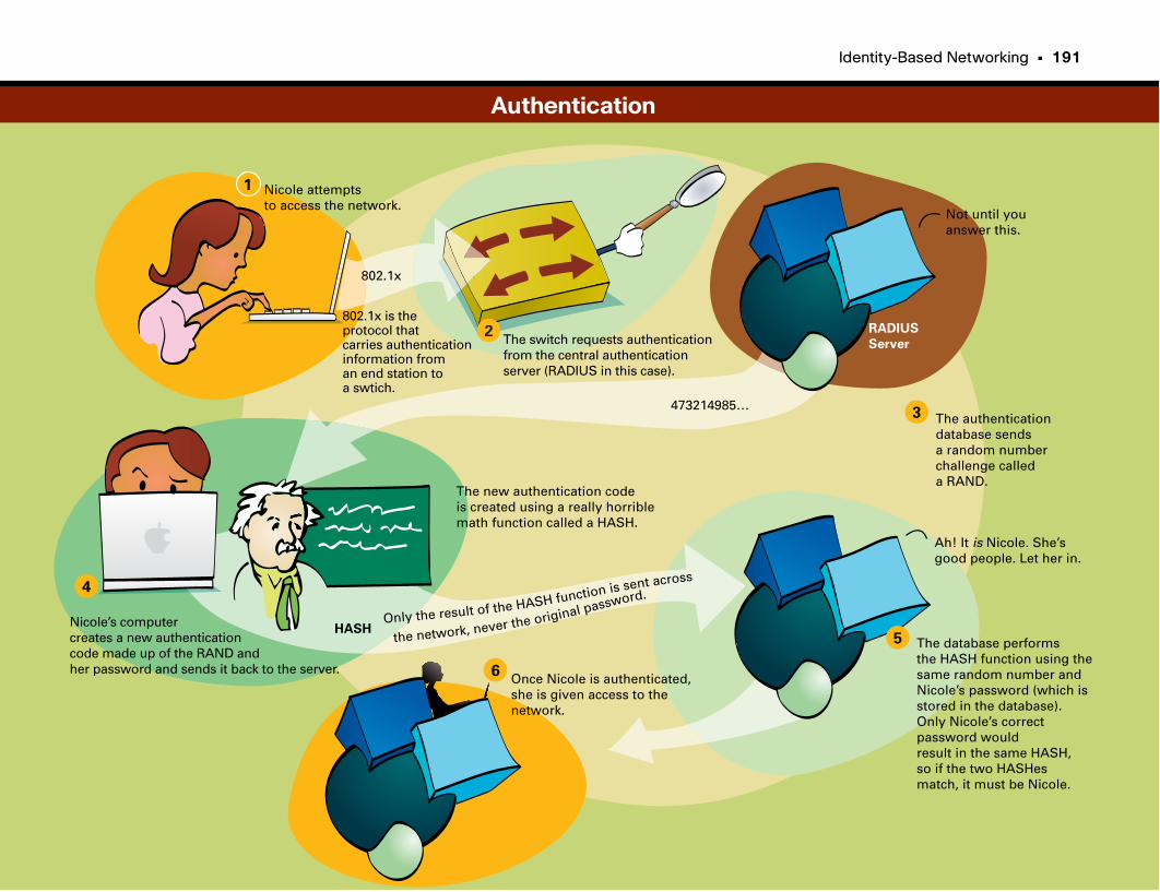
Identity-Based Networking • 191
802.1x
Nicole attempts to access the network.
802.1x is the protocol thatcarries authenticationinformation froman end station to a swtich.
The switch requests authenticationfrom the central authenticationserver (RADIUS in this case).
The authenticationdatabase sendsa random numberchallenge called a RAND.
RADIUS
Server
Not until youanswer this.
473214985…
Nicole’s computer creates a new authenticationcode made up of the RAND andher password and sends it back to the server.
The new authentication codeis created using a really horriblemath function called a HASH.
HASHThe database performs the HASH function using the same random number andNicole’s password (which is stored in the database). Only Nicole’s correct password would result in the same HASH,so if the two HASHesmatch, it must be Nicole.
Ah! It is Nicole. She’sgood people. Let her in.
Only the result of the HASH function is sent across
the network, never the original password.
Once Nicole is authenticated,she is given access to the network.
1
2
3
4
5
6
Authentication

Network Admission Control
Combating Virus OutbreaksMobility has given corporate employees huge productivity gains. They can
access corporate applications from home, while traveling, and via wireless
hotspots at coffee shops and airports. Always-on broadband networks have
also led to huge strides in productivity. Employees can work from home in the
evenings or even during extended periods when they are unable to get to
work, such as during an ice storm.
But mobility and flexibility come at a price. Increasingly, corporate computer
assets including laptops, PDAs, and handheld computers are used in public
environments—home, Wi-Fi hotspots, hotels—which are shared networks.
With shared networks also comes the opportunity for more frequent occur-
rences of computer virus infections. It’s a bit like the difference between using
a public shower and using the one in your home: You aren’t really sure who
else has used it and what bacteria might be lurking there.
IBNS takes an important step in ensuring that only authorized devices are
allowed to access the network. But what about devices that are authorized but
are infected with malicious software, such as viruses, worms, and Trojan hors-
es? Even if a device such as a laptop is being used by a legitimate employee,
that says very little about the device’s “health.” Laptops that are used outside
the corporate network and then are brought back into the corporate network
present the large threat of introducing malicious software outbreaks inside the
company.
Assessing Device “Health”Plenty of high-quality software applications are available to scan laptops and
computers for the presence of malicious software. These include antivirus,
anti-spyware, anti-adware, and software inventory programs. Many of these
programs require constant updates of their signature databases so that they
can always recognize the latest malicious software threats and prevent them
from infecting a computer. Whether the signatures are current and whether
scans have been scheduled and executed may depend on how long the comput-
er asset has been outside the corporate network, how diligent the user is, and
how well the corporate security policies keep up with new threats.
You can do several things to assess a device’s health:
• Ensure that the operating system is current and has the latest security patches
applied.
• Ensure that end-user applications (such as web browsers) have the latest
patches to close known holes or exploits.
• Ensure that any corporate-managed security agents, such as Cisco Security
Agent (CSA), are installed, are up to date, and are monitoring the computer
asset.
• Ensure that the corporate-managed antivirus program is installed, is current
with all updates applied, and has the latest virus signatures.
• Ensure that the antivirus (or other) program has heuristics enabled to detect
anomalous behavior that may indicate viruses that are not yet in the signa-
ture database.
• Ensure that the corporate-managed anti-spyware/adware program is
installed, is current with all updates applied, and has the latest signatures.
• Ensure that the corporate-managed software inventory program is installed
and is current with all updates applied.
• Ensure that all the items just listed have recently performed a “scan” of the
laptop or other computer asset and that the scan is “clean.”
Wow! That’s a lot to keep up with. Fortunately, all these security programs
have quite a bit of automation to manage retrieving signature updates, per-
forming scans, and so on.
But it’s possible that a laptop may have been away from the corporate net-
work for some time and did not have access to the necessary update files. Its
also possible that the end user canceled scanning or even disabled the pro-
grams. How can we ensure that the laptop is in compliance with the latest
security policies and is “clean”?
194 • Securing the Network
Network Admission ControlNetwork Admission Control (NAC) builds on IBNS by providing an addition-
al hurdle that devices must leap before being allowed to access the network.
After a laptop passes the identity check (assuming that IBNS is being used), the
network provides an additional challenge to the device to assess its health.
Health is determined by the corporate security policy. It typically includes
auditing the laptop for proper installation and current operation of mandatory
security software programs, such as Cisco Security Agent (CSA), antivirus,
anti-spyware/adware, and so on. The device is challenged by the network
using a special NAC protocol; it needs to provide its health credentials to the
network. The credentials are validated against a policy server. If the device is
in compliance, it is allowed to access the network.
If a device is out of compliance, the policy server determines what actions need
to be taken. Often a device out of compliance is “quarantined” to a special
segment of the network that has access to remediation servers. The latest
updates and signatures can be downloaded so that the device can come back
into compliance. The device could also be given “guest only” access so that
the device has basic Internet connectivity but no access to the internal
network.
Some devices, such as printers and other less-intelligent devices, may not be
able to participate in a NAC challenge. Such devices may not be susceptible to
the same malicious software threats, so they may be exempted. The corporate
security policy must specify how these devices are to be handled.
Finally, NAC can be implemented in the network in a couple different ways.
The access switches may provide the NAC challenge, similar to how they pro-
vide an IBNS challenge. Alternatively, a dedicated set of NAC appliances may
provide the challenges further into the network. In either case, NAC can play a
critical role in keeping infected devices off the network, where they are likely
to infect others.
Network Admission Control • 195
Why Should I Care About NetworkAdmission Control?Not too long ago your work computer not only
remained at work, it never even moved from your
desk. Today, however, your computer probably
goes home with you every night, accompanies you
on business trips, and maybe even travels with you
on vacation. While accompanying you away from
work, your computer connects to the corporate
network from many different locations from your
home, through a Wi-Fi hotspot, from a hotel room,
and even from another company’s network as a
guest user. In addition, many companies allow their
employees to access the Internet for personal use.
Although this is great for productivity, this type of
mobility also brings many opportunities for
employee computers to become infected with virus-
es, spyware, or other forms of malware.
When infected laptops or other computers are rein-
troduced into the corporate environment, there is a
tremendous opportunity for them to impact other
users and devices on the network.
NAC allows network administrators to keep infect-
ed computers from gaining network access. This
prevents widespread outbreaks, which can cost
companies significant productivity losses or cause
irretrievable data loss.
What Does NAC Do, Exactly?The presence of a NAC solution adds an addition-
al qualification (beyond login/password or require-
ment) that must be satisfied before an end-user
device is granted access to the network. The device
must be compliant with policy (have the updated
antivirus signatures) and health (not be currently
infected) requirements.
Policy checking can include the following:
• Ensuring that the most recent versions of
antivirus software and signatures are installed.
• Ensuring that a virus scan has been performed
recently.
• Ensuring that the device is free of viruses, spy-
ware, and other forms of malware.
• Ensuring that other policies as defined by the IT
department have been complied with.
A NAC solution has the following components:
• Subjects: The devices seeking network access
• Enforcement points: The network devices
enforcing the IT policies
• Decision services: Where “intelligence” about
the policies is contained
What Problems Need to Be Solved?Several challenges exist with respect to controlling
the health of devices on the network:
• Consistent policy enforcement: Signatures and
revisions for antivirus software and other prod-
ucts must be kept up to date on end-user work-
stations, especially laptops.
• Blocking known infections: Infected end-user
devices must be blocked from accessing the net-
work and potentially infecting others.
• Remediation: Inoculations must be provided for
infected devices to get users back on the net-
work.
In addition to these policy challenges, other com-
plicating factors exist:
• There are many different types of end-user
devices, with different operating systems.
• Some devices, such as printers, handheld IP-
enabled scanners, and servers, to name just a
few, may not be able to respond to challenges
regarding their policy health.
• Infected devices need access to some level of
network services, isolated from the rest of the
network, to install the needed remediation to
reinstate their health.
• The cost (time) of a challenge cannot excessively
hinder productivity or delay network access in
emergency situations.
At-a-Glance: NAC
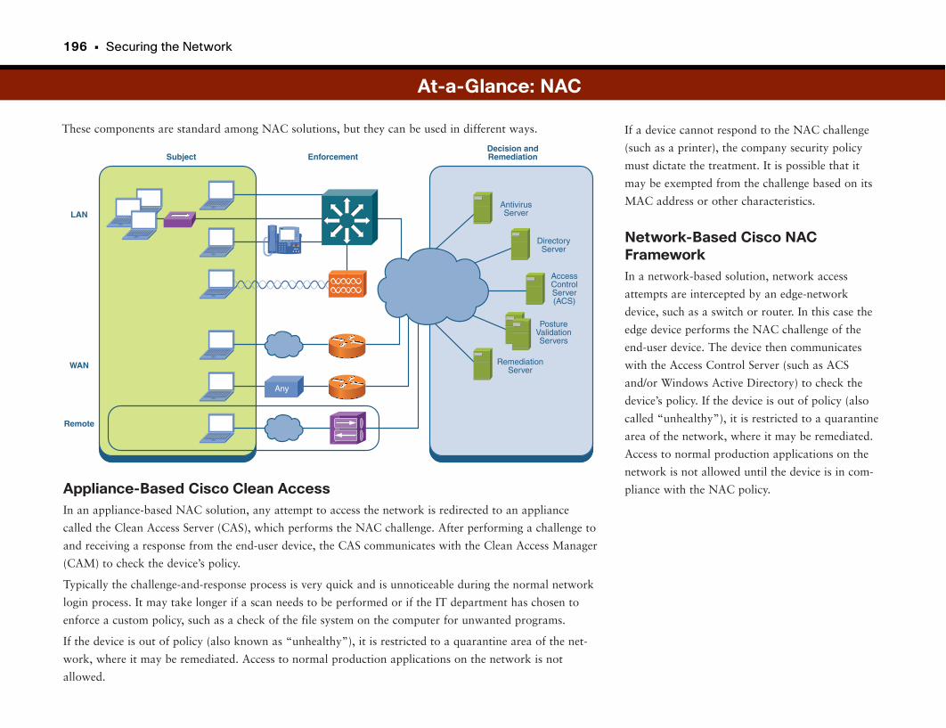
196 • Securing the Network
These components are standard among NAC solutions, but they can be used in different ways. If a device cannot respond to the NAC challenge
(such as a printer), the company security policy
must dictate the treatment. It is possible that it
may be exempted from the challenge based on its
MAC address or other characteristics.
Network-Based Cisco NACFrameworkIn a network-based solution, network access
attempts are intercepted by an edge-network
device, such as a switch or router. In this case the
edge device performs the NAC challenge of the
end-user device. The device then communicates
with the Access Control Server (such as ACS
and/or Windows Active Directory) to check the
device’s policy. If the device is out of policy (also
called “unhealthy”), it is restricted to a quarantine
area of the network, where it may be remediated.
Access to normal production applications on the
network is not allowed until the device is in com-
pliance with the NAC policy.Appliance-Based Cisco Clean AccessIn an appliance-based NAC solution, any attempt to access the network is redirected to an appliance
called the Clean Access Server (CAS), which performs the NAC challenge. After performing a challenge to
and receiving a response from the end-user device, the CAS communicates with the Clean Access Manager
(CAM) to check the device’s policy.
Typically the challenge-and-response process is very quick and is unnoticeable during the normal network
login process. It may take longer if a scan needs to be performed or if the IT department has chosen to
enforce a custom policy, such as a check of the file system on the computer for unwanted programs.
If the device is out of policy (also known as “unhealthy”), it is restricted to a quarantine area of the net-
work, where it may be remediated. Access to normal production applications on the network is not
allowed.
At-a-Glance: NAC
Subject
LAN
WAN
Remote
Decision andRemediationEnforcement
Any
AccessControlServer(ACS)
DirectoryServer
PostureValidationServers
RemediationServer
AntivirusServer
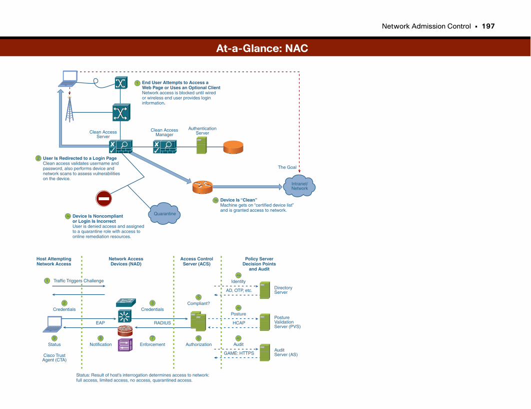
Network Admission Control • 197
At-a-Glance: NAC
4c
Audit
4b
Posture
5
4a
Identity
Compliant?
6Authorization
3Credentials
7Enforcement
2
1
Credentials
8Notification
9Status
Cisco TrustAgent (CTA)
Policy ServerDecision Points
and Audit
Access ControlServer (ACS)
Network AccessDevices (NAD)
Host AttemptingNetwork Access
AD, OTP, etc.
HCAPRADIUSEAP
Status: Result of host’s interrogation determines access to network:full access, limited access, no access, quarantined access.
DirectoryServer
PostureValidationServer (PVS)
GAME: HTTPSAuditServer (AS)
Traffic Triggers Challenge
The Goal
Intranet/Network
End User Attempts to Access aWeb Page or Uses an Optional ClientNetwork access is blocked until wiredor wireless end user provides logininformation.
1
User Is Redirected to a Login PageClean access validates username andpassword, also performs device andnetwork scans to assess vulnerabilitieson the device.
2
Device Is Noncompliant or Login Is IncorrectUser is denied access and assignedto a quarantine role with access to online remediation resources.
3a
Device Is “Clean”Machine gets on “certified device list”and is granted access to network.
3b
Clean AccessManager
MGR
AuthenticationServerClean Access
Server
Quarantine
URL Filtering: Eliminating Unwanted Web Page Access
Internet Access and Liability IssuesThe Internet has provided quite possibly the single largest increase in commu-
nications and productivity in modern history. Whether it is keeping up with
the latest news, researching a subject, purchasing supplies and components, or
blogging with others in a community of interest on a particular topic, the
Internet has provided a platform that has revolutionized work, home, and edu-
cational environments.
But not everything on the Internet is appropriate for all audiences, at all times,
and in all contexts. For example, it is up to each individual whether to access
gambling and adult websites from home, but these websites are usually inap-
propriate for the work environment. Some inappropriate content can even lead
to liability issues for corporations. For example, employees viewing pornogra-
phy at work could expose others to the images, which could lead to harass-
ment lawsuits with serious financial consequences.
Still other websites, such as sports fantasy leagues, social networking sites, and
auction sites, may not violate rules of appropriate content, but they can be a
drain on employee productivity.
Enforcing Corporate Internet Usage PoliciesEnforcing which Internet websites employees may and may not use is a bit
tricky. Some websites are pretty obvious, such as online gambling and adult
sites. For these sites it is a matter of maintaining a list of restricted websites.
Other sites may not be as clear-cut. For example, it can be argued that online
news sites are best viewed at home. However, it can also be argued that the
same sites provide valuable business-relevant information, such as on regulato-
ry issues, global economic events, and even important product releases from a
competitor. For Internet websites that fall into this “gray area,” each company
must determine its own definition of “appropriate.”
After this has been determined, access to websites that are within corporate
policy can be enforced through help from the network using techniques includ-
ing URL filtering. URL filtering essentially compares a website entered by an
employee against a database of restricted websites. If the website is not in the
list, access is granted. If it is in the list, typically the employee is given a warn-
ing screen that indicates he is trying to access a restricted web page.
These lists can also be time-based in cases where a company doesn’t really care
what websites the employees visit; it just doesn’t want the web traffic to mess
up the business traffic during peak work hours.
URL filtering is only as good as the list of restricted websites, which must be
continually updated, similar to antivirus signatures. More-sophisticated web
filtering techniques can involve scanning the target web page for inappropriate
content and making an “on-the-fly” assessment of appropriateness based on
the content itself rather than the URL. Content scanning can be fairly effective
for text content, but it can lose its effectiveness as the content becomes more
rich-media-oriented, such as pictures, video, and flash animations. Rich media
is more difficult to scan to determine its appropriateness.
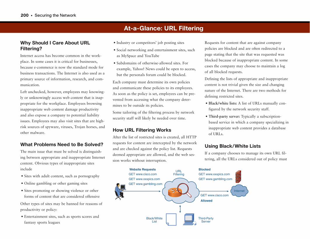
200 • Securing the Network
Why Should I Care About URLFiltering?Internet access has become common in the work-
place. In some cases it is critical for businesses,
because e-commerce is now the standard mode for
business transactions. The Internet is also used as a
primary source of information, research, and com-
munication.
Left unchecked, however, employees may knowing-
ly or unknowingly access web content that is inap-
propriate for the workplace. Employees browsing
inappropriate web content damage productivity
and also expose a company to potential liability
issues. Employees may also visit sites that are high-
risk sources of spyware, viruses, Trojan horses, and
other malware.
What Problems Need to Be Solved?The main issue that must be solved is distinguish-
ing between appropriate and inappropriate Internet
content. Obvious types of inappropriate sites
include
• Sites with adult content, such as pornography
• Online gambling or other gaming sites
• Sites promoting or showing violence or other
forms of content that are considered offensive
Other types of sites may be banned for reasons of
productivity or policy:
• Entertainment sites, such as sports scores and
fantasy sports leagues
Requests for content that are against company
policies are blocked and are often redirected to a
page stating that the site that was requested was
blocked because of inappropriate content. In some
cases the company may choose to maintain a log
of all blocked requests.
Defining the lists of appropriate and inappropriate
content is not trivial given the size and changing
nature of the Internet. There are two methods for
defining restricted sites.
• Black/white lists: A list of URLs manually con-
figured by the network security staff.
• Third-party server: Typically a subscription-
based service in which a company specializing in
inappropriate web content provides a database
of URLs.
Using Black/White ListsIf a company chooses to manage its own URL fil-
tering, all the URLs considered out of policy must
• Industry or competitors’ job posting sites
• Social networking and entertainment sites, such
as MySpace and YouTube
• Subdomains of otherwise-allowed sites. For
example, Yahoo! News could be open to access,
but the personals forum could be blocked.
Each company must determine its own policies
and communicate these policies to its employees.
As soon as the policy is set, employees can be pre-
vented from accessing what the company deter-
mines to be outside its policies.
Some tailoring of the filtering process by network
security staff will likely be needed over time.
How URL Filtering WorksAfter the list of restricted sites is created, all HTTP
requests for content are intercepted by the network
and are checked against the policy list. Requests
deemed appropriate are allowed, and the web ses-
sion works without interruption.
At-a-Glance: URL Filtering
Internet
Website Requests
GET www.cisco.com
GET www.xxxpics.com
GET www.gambling.com
Blocked
GET www.xxxpics.com
GET www.gambling.com
Allowed
GET www.cisco.com
Third-PartyServer
URLFiltering
Black/WhiteList
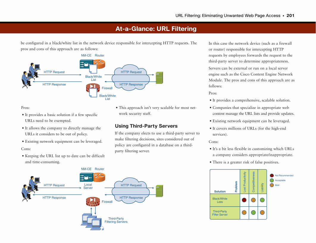
URL Filtering: Eliminating Unwanted Web Page Access • 201
be configured in a black/white list in the network device responsible for intercepting HTTP requests. The
pros and cons of this approach are as follows:In this case the network device (such as a firewall
or router) responsible for intercepting HTTP
requests by employees forwards the request to the
third-party server to determine appropriateness.
Servers can be external or run on a local server
engine such as the Cisco Content Engine Network
Module. The pros and cons of this approach are as
follows:
Pros:
• It provides a comprehensive, scalable solution.
• Companies that specialize in appropriate web
content manage the URL lists and provide updates.
• Existing network equipment can be leveraged.
• It covers millions of URLs (for the high-end
services).
Cons:
• It’s a bit less flexible in customizing which URLs
a company considers appropriate/inappropriate.
• There is a greater risk of false positives.
Pros:
• It provides a basic solution if a few specific
URLs need to be exempted.
• It allows the company to directly manage the
URLs it considers to be out of policy.
• Existing network equipment can be leveraged.
Cons:
• Keeping the URL list up to date can be difficult
and time-consuming.
Black/WhiteLists
Lost
Pro
duct
ivity
Pro
ble
m
Com
petit
iven
ess
Liab
ility
Not Recommended
Solution
Third-PartyFilter Server
Acceptable
Best
At-a-Glance: URL Filtering
Router
Firewall
NM-CE
Black/WhiteList
Black/WhiteList
HTTP Request
HTTP Response
HTTP Request
HTTP Response
Router
Firewall
Third-PartyFiltering Servers
NM-CE
LocalServer
HTTP Request
HTTP Response
HTTP Request
HTTP Response
• This approach isn’t very scalable for most net-
work security staff.
Using Third-Party ServersIf the company elects to use a third-party server to
make filtering decisions, sites considered out of
policy are configured in a database on a third-
party filtering server.
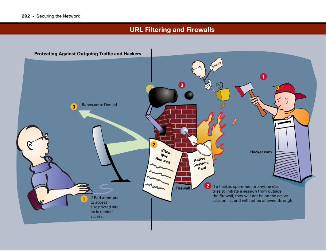
1
2
3
1
2
3
Protecting Against Outgoing Traffic and Hackers
SitesNotAllowed Active
Session:
Paul
Firewall
Hacker.com
Babes.com: Denied
If a hacker, spammer, or anyone elsetries to initiate a session from outsidethe firewall, they will not be on the active session list and will not be allowed through.
Invite
If Earl attempts to accessa restricted site, he is deniedaccess.
URL Filtering and Firewalls
202 • Securing the Network

This page intentionally left blank
Deep Packet Inspection: Controlling Unwanted Applications
How Do You Catch a Criminal When Everyone Wears a Mask?Traditional firewalls can be very effective against network intrusions in which
packets are sent from an untrusted network to a trusted one. The IP protocol
being used can be checked for appropriateness and to ensure that it is part of a
conversation that originated from the trusted side. In this way, security attacks
that rely on manipulating certain IP protocols can be halted.
Increasingly, the number of IP protocols used on the network and the Internet
is narrowing dramatically. With the popularity of TCP/IP applications, and
even more so web-based applications using HTTP, the vast majority of traffic
on modern networks ends up being only a couple of IP protocols. In addition,
some protocols encapsulate themselves in other IP protocols to avoid problems
with firewalls. For example, IPsec may be encapsulated within UDP packets.
RTP video streams may be encapsulated within TCP. Finally, when nearly
every corporate application becomes a web-based application, HTTP is the
predominant protocol.
One of the issues with the huge popularity of protocols such as HTTP and
TCP is that we can lose some visibility into what is actually going on with
applications on the network. Imagine that all the customers in a bank are
wearing masks. The bank gets robbed by people in masks, and the police show
up. How are they to figure out who are the criminals and who are the inno-
cent customers?
Deep Packet InspectionDeep Packet Inspection (DPI) is a technique that allows network security
devices such as firewalls to look “deeper” into the IP packet to try to learn its
true intent. Instead of relying on fairly standard packet header information
(essentially Layers 2 and 3), which again is starting to look the same for every
application on the network, DPI can look much further up the OSI stack, into
Layers 4 through 7.
With the increased visibility that DPI provides, it is possible for network secu-
rity devices to understand more about the actual applications being run across
the network, what information is being passed, and whether the information is
appropriate in the context.
DPI has other potential applications as well. Although we certainly want to
halt bad traffic, we also want to accelerate critical traffic. DPI can be one tool
used to recognize which applications on the network are vital to the compa-
ny’s business and to give those applications preferential treatment as they are
routed through the network.
Finally, a note about encryption. Encryption can be a very effective way to
secure communications between two devices, whether it is a laptop encrypting
a session across the Internet to the corporate headquarters (such as with IPSec
VPN) or securing a voice-over-IP phone call between two IP phones (such as
with SRTP).
The downside is that encrypted packets do not lend themselves well to being
inspected. Typically network security devices do not have access to the decryp-
tion keys required to decode the encrypted packets and to understand what is
occurring in the packet conversation. This is an example where one security
policy may make it exceptionally difficult to enforce another.

206 • Securing the Network
Why Should I Care About DeepPacket Inspection?Despite the steady growth in the availability of
high-speed network links, companies still find that
the bandwidth is constrained. This is due in part to
the explosion of increased bandwidth needs of
applications such as voice and video, as well as an
overall increase in the number of applications in use.
This issue is often compounded when employees use
applications such as file sharing and peer-to-peer
programs that are not critical to the business.
Because of these bandwidth constraints, companies
must ensure that the bandwidth they have is used
efficiently.
Tools such as QoS allow businesses to control
which applications receive priority for network
resources, but there is still a gap in terms of block-
ing applications deemed unnecessary for employees
to use.
Companies must also guard against the propaga-
tion of worms and DoS attacks. Antivirus can help
keep malware off employee computers, but the net-
work must be able to recognize and block traffic
related to such outbreaks.
Deep packet inspection is a tool that allows com-
panies to look inside a packet to determine
whether the packet should be dropped, without
causing unbearable delays.
— Instant messaging
— Social networking applications, such as
MySpace
As soon as the types of threats and applications
have been identified, a method must be developed
to get rid of all packets that meet the drop criteria,
without impacting the packets you want to keep.
Some tailoring of application filtering may be
required by network administrators to ensure a
good fit with company policies.
What Problems Need to Be Solved?Because the whole point of deep packet inspection
is to know which packets can be dropped, you
first need to determine what you want to get rid
of. Typical areas of concern are
• Malicious applications such as worms, viruses,
and DoS attacks
• Noncritical applications
— File-sharing programs designed to share
music files between peers
At-a-Glance: Deep Packet Inspection
Si Si
Campus
Worm X VIrus Z Worm Y
Si
Si
SiSi
Si
Si
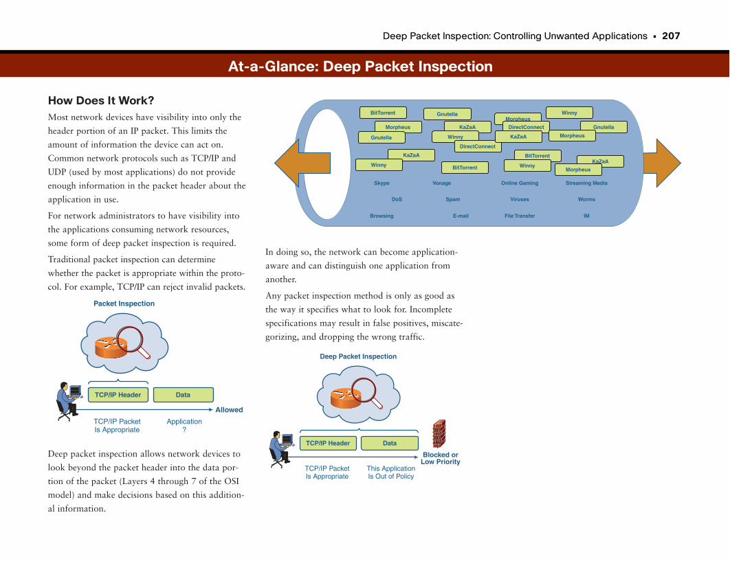
Deep Packet Inspection: Controlling Unwanted Applications • 207
How Does It Work?Most network devices have visibility into only the
header portion of an IP packet. This limits the
amount of information the device can act on.
Common network protocols such as TCP/IP and
UDP (used by most applications) do not provide
enough information in the packet header about the
application in use.
For network administrators to have visibility into
the applications consuming network resources,
some form of deep packet inspection is required.
Traditional packet inspection can determine
whether the packet is appropriate within the proto-
col. For example, TCP/IP can reject invalid packets.
Deep packet inspection allows network devices to
look beyond the packet header into the data por-
tion of the packet (Layers 4 through 7 of the OSI
model) and make decisions based on this addition-
al information.
At-a-Glance: Deep Packet Inspection
Blocked orLow Priority
Deep Packet Inspection
TCP/IP PacketIs Appropriate
This ApplicationIs Out of Policy
TCP/IP Header Data
Allowed
Packet Inspection
TCP/IP PacketIs Appropriate
Application?
TCP/IP Header Data
BitTorrent GnutellaMorpheus
Winny
Morpheus
Gnutella
KaZaA
Winny
KaZaA
Winny
DirectConnect
BitTorrent
DirectConnect
KaZaA
BitTorrent
Winny
Gnutella
Morpheus
KaZaA
Morpheus
Skype
DoS
Browsing
Vonage
Spam
Online Gaming
Viruses
File Transfer
Streaming Media
Worms
IM
In doing so, the network can become application-
aware and can distinguish one application from
another.
Any packet inspection method is only as good as
the way it specifies what to look for. Incomplete
specifications may result in false positives, miscate-
gorizing, and dropping the wrong traffic.
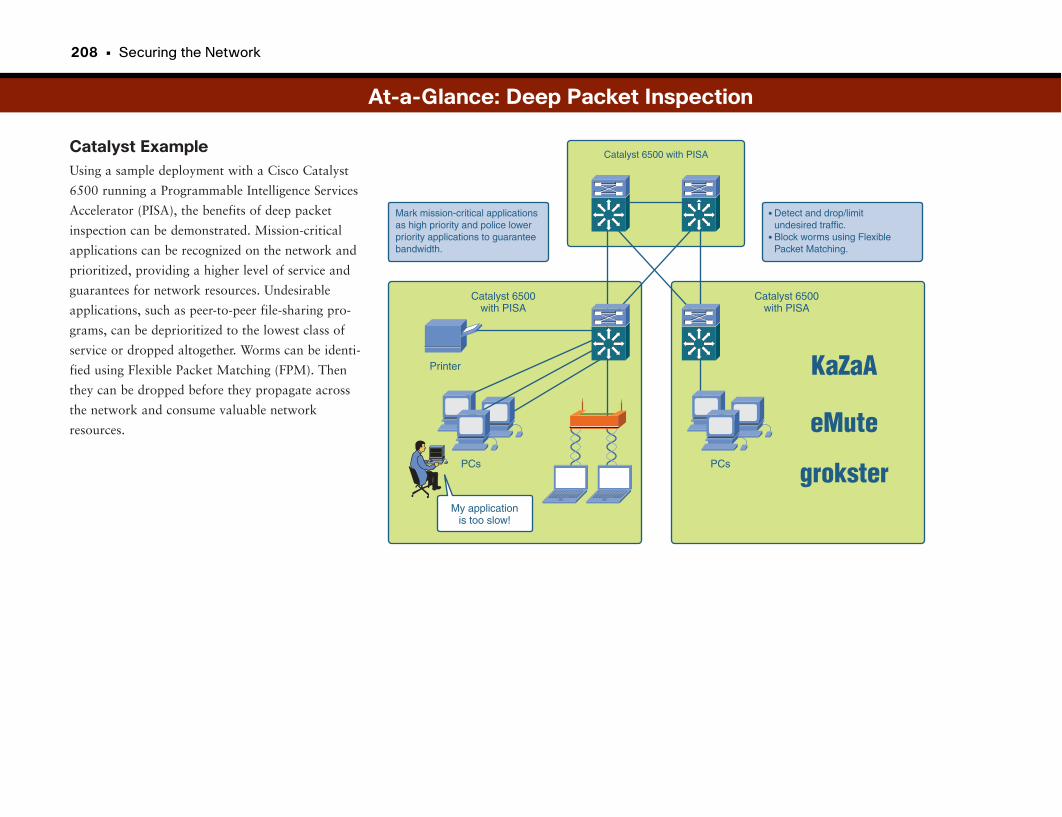
208 • Securing the Network
Catalyst ExampleUsing a sample deployment with a Cisco Catalyst
6500 running a Programmable Intelligence Services
Accelerator (PISA), the benefits of deep packet
inspection can be demonstrated. Mission-critical
applications can be recognized on the network and
prioritized, providing a higher level of service and
guarantees for network resources. Undesirable
applications, such as peer-to-peer file-sharing pro-
grams, can be deprioritized to the lowest class of
service or dropped altogether. Worms can be identi-
fied using Flexible Packet Matching (FPM). Then
they can be dropped before they propagate across
the network and consume valuable network
resources.
At-a-Glance: Deep Packet Inspection
PCs
Printer
Catalyst 6500with PISA
KaZaA
eMute
grokster
Catalyst 6500with PISA
My applicationis too slow!
Mark mission-critical applications as high priority and police lower priority applications to guarantee bandwidth.
Detect and drop/limit undesired traffic.Block worms using Flexible Packet Matching.
•
•
Catalyst 6500 with PISA
PCs
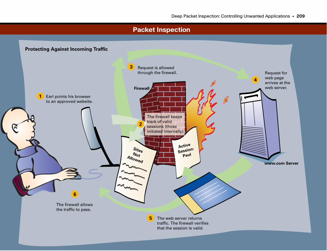
Deep Packet Inspection: Controlling Unwanted Applications • 209
1
2
3
4
5
6
Protecting Against Incoming Traffic
Earl points his browser to an approved website.
The firewall keeps track of valid sessions (those initiated internally).
Request is allowedthrough the firewall. Request for
web pagearrives at the web server.
The web server returnstraffic. The firewall verifies that the session is valid.
The firewall allows the traffic to pass.
SitesNotAllowed
Active
Session:
Paul
Firewall
www.com Server
Packet Inspection
Telemetry: Identifying and Isolating Attack Sources
Normal or AbnormalAlthough it is critical to deploy the best security tools and systems available,
including IBNS, firewalls, IPS, and NAC, it is possible to overlook one of the
most useful security tools—“hiding in plain sight.”
Using common network traffic monitoring and analysis tools (such as Cisco
NetFlow) that are available on many core Cisco network products (including
routers and switches), you can gain a deep understanding of what a network
looks like during normal operations and when an anomaly is present in the
network.
If you understand and study the normal, the abnormal can become apparent.
What comprises abnormal may vary from network to network and from
attack to attack. It could include large traffic spikes from a single source in the
network, higher-than-typical traffic “bursts” from several or many devices in
the network, or traffic types detected that are not normally sent from a known
device type.
Detection is half the battle, and understanding what is normal can give net-
work administrators the visibility needed to more easily notice anomalies.
Telemetry is a way to provide a statistics-based analysis and management of
network anomalies. This is different from packet inspections, because the
telemetry system doesn’t look at the actual data in the packet. It simply looks
at traffic patterns. Over time it can differentiate between normal traffic levels,
acceptable anomalies, and anomalous behaviors that look like attacks.
Using Telemetry to Combat AttacksAfter an anomaly or anomalies are identified, the sources must be found and
eliminated. Again, understanding the normal behavior of hosts and different
device types on the network, including applications that are normally present
in a business, is critical to isolating attack sources.
Using a suite of tools available on the network, hosts originating the attack
vector (whether knowingly or unknowingly) can be isolated, and appropriate
actions can be taken on the network to halt traffic as close to the sources as
possible.
Finally, network administrators can schedule remediation for the affected hosts
to remove the malicious software enabling the compromise, and being used for
coordinated attack vectors, such as a DDoS attack from within the business
itself, using the business’s own computer assets.
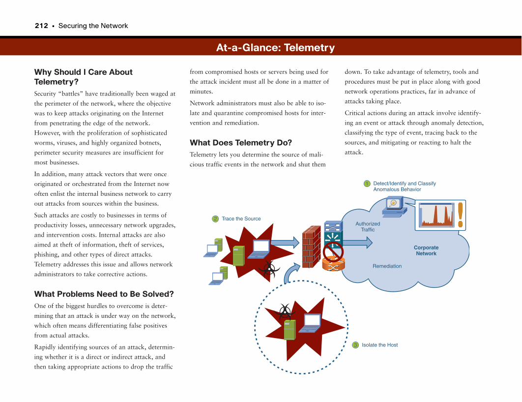
212 • Securing the Network
Why Should I Care AboutTelemetry?Security “battles” have traditionally been waged at
the perimeter of the network, where the objective
was to keep attacks originating on the Internet
from penetrating the edge of the network.
However, with the proliferation of sophisticated
worms, viruses, and highly organized botnets,
perimeter security measures are insufficient for
most businesses.
In addition, many attack vectors that were once
originated or orchestrated from the Internet now
often enlist the internal business network to carry
out attacks from sources within the business.
Such attacks are costly to businesses in terms of
productivity losses, unnecessary network upgrades,
and intervention costs. Internal attacks are also
aimed at theft of information, theft of services,
phishing, and other types of direct attacks.
Telemetry addresses this issue and allows network
administrators to take corrective actions.
What Problems Need to Be Solved?One of the biggest hurdles to overcome is deter-
mining that an attack is under way on the network,
which often means differentiating false positives
from actual attacks.
Rapidly identifying sources of an attack, determin-
ing whether it is a direct or indirect attack, and
then taking appropriate actions to drop the traffic
down. To take advantage of telemetry, tools and
procedures must be put in place along with good
network operations practices, far in advance of
attacks taking place.
Critical actions during an attack involve identify-
ing an event or attack through anomaly detection,
classifying the type of event, tracing back to the
sources, and mitigating or reacting to halt the
attack.
from compromised hosts or servers being used for
the attack incident must all be done in a matter of
minutes.
Network administrators must also be able to iso-
late and quarantine compromised hosts for inter-
vention and remediation.
What Does Telemetry Do?Telemetry lets you determine the source of mali-
cious traffic events in the network and shut them
At-a-Glance: Telemetry
Detect/Identify and ClassifyAnomalous Behavior
1
Trace the Source2 !
Isolate the Host3
AuthorizedTraffic
Remediation
CorporateNetwork
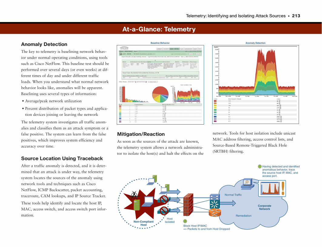
Telemetry: Identifying and Isolating Attack Sources • 213
Anomaly DetectionThe key to telemetry is baselining network behav-
ior under normal operating conditions, using tools
such as Cisco NetFlow. This baseline test should be
performed over several days (or even weeks) at dif-
ferent times of day and under different traffic
loads. When you understand what normal network
behavior looks like, anomalies will be apparent.
Baselining uses several types of information:
• Average/peak network utilization
• Percent distribution of packet types and applica-
tion devices joining or leaving the network
The telemetry system investigates all traffic anom-
alies and classifies them as an attack symptom or a
false positive. The system can learn from the false
positives, which improves system efficiency and
accuracy over time.
Source Location Using TracebackAfter a traffic anomaly is detected, and it is deter-
mined that an attack is under way, the telemetry
system locates the sources of the anomaly using
network tools and techniques such as Cisco
NetFlow, ICMP Backscatter, packet accounting,
traceroute, CAM lookups, and IP Source Tracker.
These tools help identify and locate the host IP,
MAC, access switch, and access switch port infor-
mation.
network. Tools for host isolation include unicast
MAC address filtering, access control lists, and
Source-Based Remote-Triggered Black Hole
(SRTBH) filtering.
Having detected and identifiedanomalous behavior, tracethe source host IP, MAC, andaccess port.
1
Block Host IP/MAC=> Packets to and from Host Dropped
2
!Normal Traffic
Remediation
CorporateNetwork
HostIsolatedNon-Compliant
Host
At-a-Glance: Telemetry
Anomaly DetectionBaseline Behavior
Mitigation/ReactionAs soon as the sources of the attack are known,
the telemetry system allows a network administra-
tor to isolate the host(s) and halt the effects on the
Physical Security: IP Video Surveillance
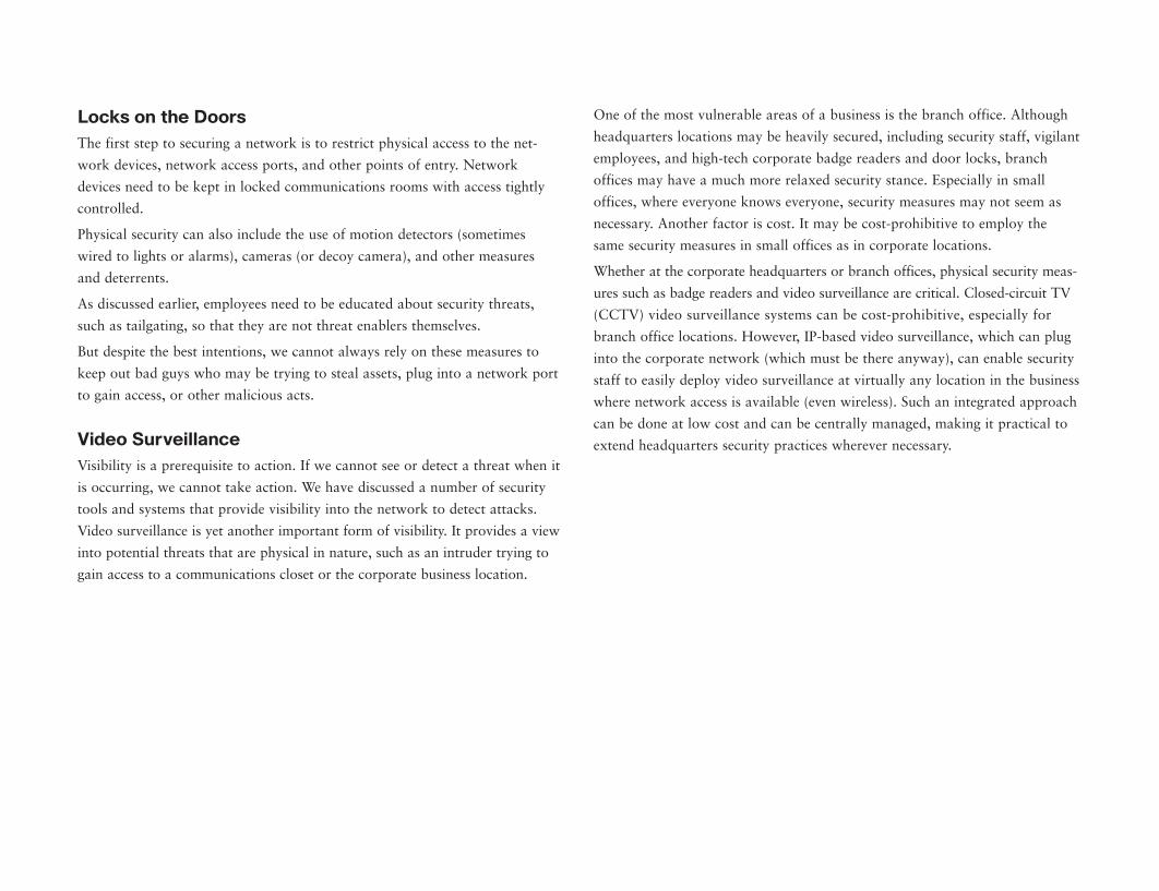
Locks on the DoorsThe first step to securing a network is to restrict physical access to the net-
work devices, network access ports, and other points of entry. Network
devices need to be kept in locked communications rooms with access tightly
controlled.
Physical security can also include the use of motion detectors (sometimes
wired to lights or alarms), cameras (or decoy camera), and other measures
and deterrents.
As discussed earlier, employees need to be educated about security threats,
such as tailgating, so that they are not threat enablers themselves.
But despite the best intentions, we cannot always rely on these measures to
keep out bad guys who may be trying to steal assets, plug into a network port
to gain access, or other malicious acts.
Video SurveillanceVisibility is a prerequisite to action. If we cannot see or detect a threat when it
is occurring, we cannot take action. We have discussed a number of security
tools and systems that provide visibility into the network to detect attacks.
Video surveillance is yet another important form of visibility. It provides a view
into potential threats that are physical in nature, such as an intruder trying to
gain access to a communications closet or the corporate business location.
One of the most vulnerable areas of a business is the branch office. Although
headquarters locations may be heavily secured, including security staff, vigilant
employees, and high-tech corporate badge readers and door locks, branch
offices may have a much more relaxed security stance. Especially in small
offices, where everyone knows everyone, security measures may not seem as
necessary. Another factor is cost. It may be cost-prohibitive to employ the
same security measures in small offices as in corporate locations.
Whether at the corporate headquarters or branch offices, physical security meas-
ures such as badge readers and video surveillance are critical. Closed-circuit TV
(CCTV) video surveillance systems can be cost-prohibitive, especially for
branch office locations. However, IP-based video surveillance, which can plug
into the corporate network (which must be there anyway), can enable security
staff to easily deploy video surveillance at virtually any location in the business
where network access is available (even wireless). Such an integrated approach
can be done at low cost and can be centrally managed, making it practical to
extend headquarters security practices wherever necessary.
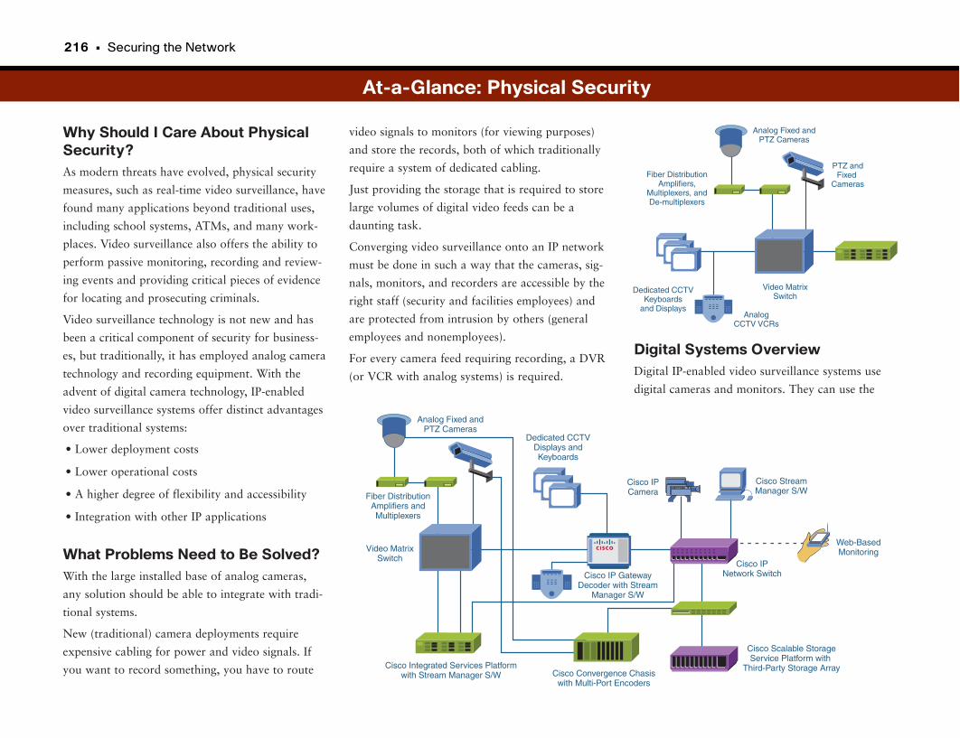
216 • Securing the Network
Why Should I Care About PhysicalSecurity?As modern threats have evolved, physical security
measures, such as real-time video surveillance, have
found many applications beyond traditional uses,
including school systems, ATMs, and many work-
places. Video surveillance also offers the ability to
perform passive monitoring, recording and review-
ing events and providing critical pieces of evidence
for locating and prosecuting criminals.
Video surveillance technology is not new and has
been a critical component of security for business-
es, but traditionally, it has employed analog camera
technology and recording equipment. With the
advent of digital camera technology, IP-enabled
video surveillance systems offer distinct advantages
over traditional systems:
• Lower deployment costs
• Lower operational costs
• A higher degree of flexibility and accessibility
• Integration with other IP applications
What Problems Need to Be Solved?With the large installed base of analog cameras,
any solution should be able to integrate with tradi-
tional systems.
New (traditional) camera deployments require
expensive cabling for power and video signals. If
you want to record something, you have to route
Digital Systems OverviewDigital IP-enabled video surveillance systems use
digital cameras and monitors. They can use the
video signals to monitors (for viewing purposes)
and store the records, both of which traditionally
require a system of dedicated cabling.
Just providing the storage that is required to store
large volumes of digital video feeds can be a
daunting task.
Converging video surveillance onto an IP network
must be done in such a way that the cameras, sig-
nals, monitors, and recorders are accessible by the
right staff (security and facilities employees) and
are protected from intrusion by others (general
employees and nonemployees).
For every camera feed requiring recording, a DVR
(or VCR with analog systems) is required.
At-a-Glance: Physical Security
Cisco IP GatewayDecoder with Stream
Manager S/W
Dedicated CCTVDisplays andKeyboards
Cisco IPNetwork Switch
Web-BasedMonitoring
Cisco IPCamera
Cisco StreamManager S/W
Cisco Scalable StorageService Platform with
Third-Party Storage ArrayCisco Integrated Services Platformwith Stream Manager S/W
Video MatrixSwitch
Fiber DistributionAmplifiers andMultiplexers
Analog Fixed andPTZ Cameras
Cisco Convergence Chasiswith Multi-Port Encoders
Video MatrixSwitch
Dedicated CCTVKeyboards
and Displays
Fiber DistributionAmplifiers,
Multiplexers, andDe-multiplexers
Analog Fixed andPTZ Cameras
PTZ andFixed
Cameras
AnalogCCTV VCRs
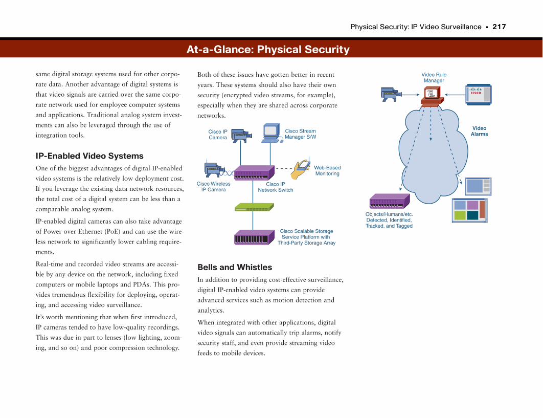
Physical Security: IP Video Surveillance • 217
same digital storage systems used for other corpo-
rate data. Another advantage of digital systems is
that video signals are carried over the same corpo-
rate network used for employee computer systems
and applications. Traditional analog system invest-
ments can also be leveraged through the use of
integration tools.
IP-Enabled Video SystemsOne of the biggest advantages of digital IP-enabled
video systems is the relatively low deployment cost.
If you leverage the existing data network resources,
the total cost of a digital system can be less than a
comparable analog system.
IP-enabled digital cameras can also take advantage
of Power over Ethernet (PoE) and can use the wire-
less network to significantly lower cabling require-
ments.
Real-time and recorded video streams are accessi-
ble by any device on the network, including fixed
computers or mobile laptops and PDAs. This pro-
vides tremendous flexibility for deploying, operat-
ing, and accessing video surveillance.
It’s worth mentioning that when first introduced,
IP cameras tended to have low-quality recordings.
This was due in part to lenses (low lighting, zoom-
ing, and so on) and poor compression technology.
Both of these issues have gotten better in recent
years. These systems should also have their own
security (encrypted video streams, for example),
especially when they are shared across corporate
networks.
Bells and WhistlesIn addition to providing cost-effective surveillance,
digital IP-enabled video systems can provide
advanced services such as motion detection and
analytics.
When integrated with other applications, digital
video signals can automatically trip alarms, notify
security staff, and even provide streaming video
feeds to mobile devices.
At-a-Glance: Physical Security
Objects/Humans/etc.Detected, Identified,Tracked, and Tagged
Video RuleManager
VideoAlarms
Cisco IPNetwork Switch
Web-BasedMonitoring
Cisco IPCamera
Cisco StreamManager S/W
Cisco Scalable StorageService Platform with
Third-Party Storage Array
Cisco WirelessIP Camera
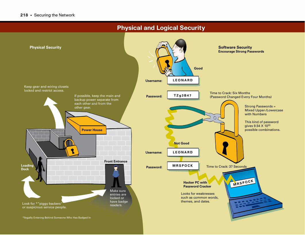
Physical Security Software SecurityEncourage Strong Passwords
Power House
If possible, keep the main andbackup power separate from each other and from the other gear.
Keep gear and wiring closets locked and restrict access.
Make sure entries arelocked or have badge readers.Look for *“piggy backers”
or suspicious service people.
Front Entrance
LoadingDock
Good
Not Good
Username:
Password:
Username:
Password:
L E O N A R D
L E O N A R D
M R S P O C K
T Z g 3 B 4 7
M R S P O C K
Time to Crack: Six Months(Password Changed Every Four Months)
Time to Crack: 37 Seconds
Hacker PC with
Password Cracker
Looks for weaknessessuch as common words, themes, and dates.
Strong Passwords = Mixed Upper-/Lowercase with Numbers
This kind of passwordgives 9.54 X 10²²
possible combinations.
*Ilegally Entering Behind Someone Who Has Badged In
Physical and Logical Security
218 • Securing the Network

This page intentionally left blank
Part VI
Data Centers and Application Networking
Moving Data EfficientlyCompanies move massive amounts of data around the network through the course of a typical day. As
companies move toward a more global approach to business, “normal” business hours have become
24-hour operations with activities and data following the sun. With all this data flying around, it is
important for companies to effectively manage their data to keep costs down and productivity up.
This part begins with a look at data centers. Data centers are just what you might think they are—
massive banks of data storage devices connected in a single location. Data centers are anything but sim-
ple, though, especially considering companies’ dependence on data. This chapter looks at how data cen-
ters work and how they interface with the rest of the network.
Before the emergence of large off-site data centers, data typically was stored at headquarters and branch
offices in smaller file servers. In some cases the data was pulled at the time it was needed. In other cases,
the data was “pushed” closer to the users before it was asked for to increase productivity. This method of
prestaging data is called caching. This chapter also looks at Storage Area Networks (SAN). SANs are still
common for smaller enterprises and are in wide use today across many networks.
Within the past several years there has been a shift in the corporate model. At one time most employees
worked at a headquarters facility, and few worked remotely or in small branch offices. Today almost
every enterprise within the Fortune 5000 has several large regional sites throughout the world that are
often considered to be headquarters facilities within their geographic region. With so many employees
outside the main headquarters, it is critical from a productivity standpoint that these employees have fast
access to the data and applications required for them to complete their missions. It is usually cost-prohibi-
tive for companies to duplicate data centers or SANs at every location, so companies must find a way to
get the most data to geographically dispersed users as fast and as efficiently as possible.
It turns out that through the use of two methods, remote users get access to information and applications
so fast, that for all they know, the data and applications reside on their local network. The section “Wide
Area File Services” looks at how large amounts of data can be moved from the data center out to remote
locations. The section “Wide Area Application Services” discusses how remote users can get local per-
formance from remote application servers.
Data Centers 223
Storage Area Networks 231
Caching 239
Wide Area File Services 243
Wide Area Application Services 249

Data Centers
The first or front tier is the actual application a user might run, such as
customer resource management (CRM), enterprise resource planning (ERP),
email, or order processing. The application might or might not be web-based,
although most modern applications use web services to some extent. This tier
provides the client-facing services.
The next tier, the middle tier, provides the glue between the client-facing appli-
cation and the back-end database and storage servers. Typically, these middle-
ware applications provide the business logic that maps corporate data to how
a company operates.
The final tier, the back end, contains all the databases, storage, and raw data
to be shared with the various applications.
Functions and RequirementsThese server farms must have a supporting network infrastructure. Although
the growth and design of data centers tend to happen gradually over time,
what evolves is a layered approach in which the data center network is divided
into distinct functions. These layered functions include the following:
• Aggregation: Connects the data center to the corporate backbone network.
• Front end: The servers that users interact with.
• Application: The servers running code that glues the front-end applications
to the back-end data and reflects the business processes in how the data is
used. Also called middleware or business-logic software.
• Back end: Where data is stored, typically in relational database systems,
such as Oracle.
• Storage: The actual storage devices in which data is stored.
• Backup: Data is stored and retrieved for either transactional or backup pur-
poses.
• Data center network transport: High-speed optical networking that facili-
tates the sharing of data between distributed data centers. Larger companies
implement distributed data centers to provide redundancy in case a server
farm or entire data center goes offline.
Store Once, Use OftenData centers are centralized locations where companies house their business-
critical network and server resources. Data centers provide secure centraliza-
tion of corporate computing resources. Mainframes, application and web
servers, Unified Communications services clusters, data storage, secure print-
ers, Internet connectivity, and network core switches are examples of devices
that are commonly located in the data center.
IT functions, such as network and server operations and support, generally sit
near the data center. Satellite data centers provide regional services as well as
disaster recovery for the primary data center. Having these resources centrally
located provides administrative benefits but also presents network-design
challenges.
Whether accessing a server in the data center, exchanging files with a remote
office worker, or accessing the Internet, most network activity passes through
the data center at some point. Additionally, the data center houses much of the
company’s critical data and computing resources. High-bandwidth networking
and business-resiliency measures become critical design factors in providing
smooth and reliable services.
Located in the data center are applications that support business-critical func-
tions as well as network operations and network-based applications, such as
IP telephony, video streaming, and IP videoconferencing.
n-Tier ModelMainframes, server farms, and blade servers represent the heart of corporate
computing resources. Today’s data-center server-farm design incorporates
what’s called an n-tier model. This model describes a method of separating
application services into manageable and secure tiers. The n indicates that
there can be any number of distinct tiers in the data center, though typically
three. The purpose of separating these functions into separate tiers is to break
the dependence of all functions residing on a single server. Separating the cus-
tomer-facing applications from the back-end servers increases the scalability of
the services and eases the management of large-scale server farms.
224 • Data Centers and Application Networking
In each case, the network must provide the infrastructure, security, and man-
agement to accommodate the requirements for each layer, including the fol-
lowing:
• High availability: Access to data center applications, data, and networking
services must continue in the event of a device or network failure.
• Scalability: Because servers are centralized in the data center, the network
must be able to handle the sheer amount of traffic from corporate users to
the central location, as well as server-to-server traffic. Additionally, data
center services must be able to scale to multiple locations when distributed
data centers are needed.
• Security: Data center devices must be physically secure, and the data and
applications must be protected from internal and external threats.
• Management: The IT staff monitors, configures, and troubleshoots network
and server resources.
• Virtualization (covered in Part IX): Instead of building redundant data cen-
ters for every division of a company, you can leverage the same data centers
across multiple entities using virtualization technologies.
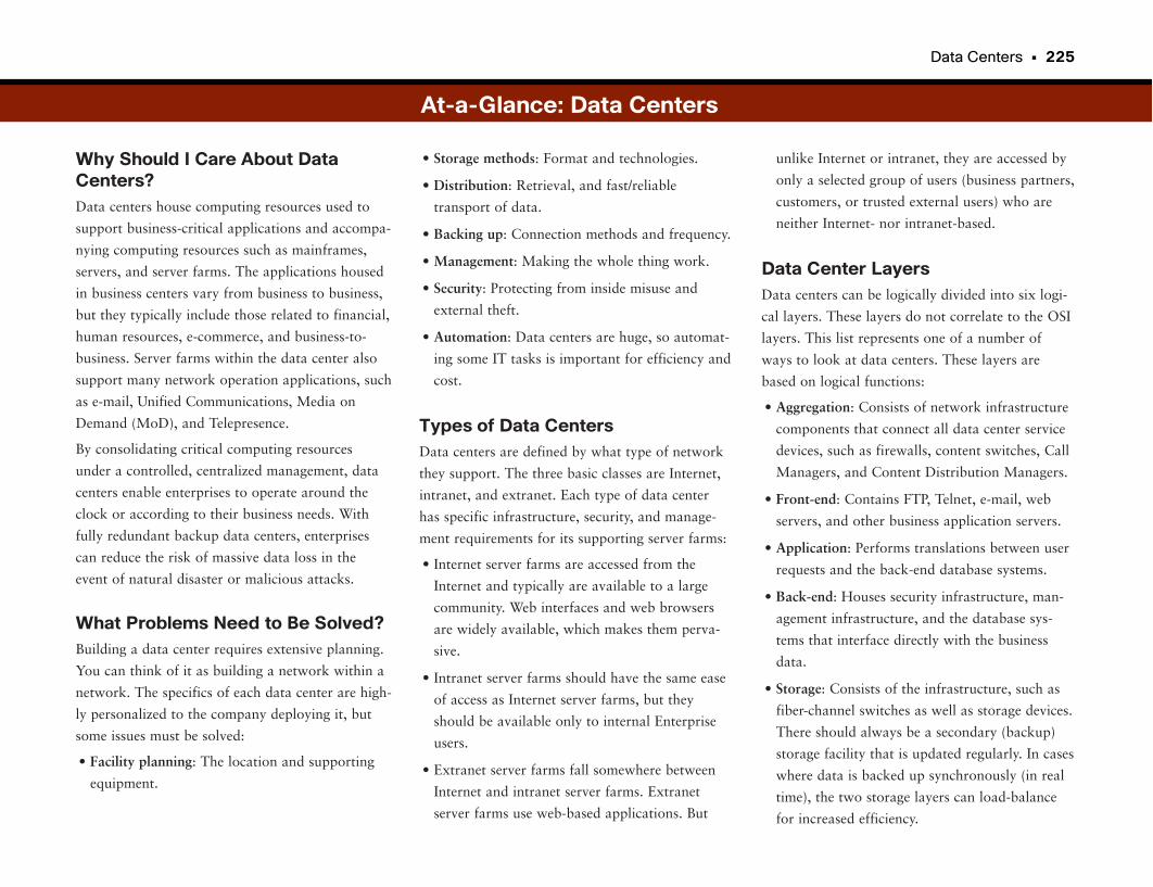
Data Centers • 225
Why Should I Care About DataCenters?Data centers house computing resources used to
support business-critical applications and accompa-
nying computing resources such as mainframes,
servers, and server farms. The applications housed
in business centers vary from business to business,
but they typically include those related to financial,
human resources, e-commerce, and business-to-
business. Server farms within the data center also
support many network operation applications, such
as e-mail, Unified Communications, Media on
Demand (MoD), and Telepresence.
By consolidating critical computing resources
under a controlled, centralized management, data
centers enable enterprises to operate around the
clock or according to their business needs. With
fully redundant backup data centers, enterprises
can reduce the risk of massive data loss in the
event of natural disaster or malicious attacks.
What Problems Need to Be Solved?Building a data center requires extensive planning.
You can think of it as building a network within a
network. The specifics of each data center are high-
ly personalized to the company deploying it, but
some issues must be solved:
• Facility planning: The location and supporting
equipment.
unlike Internet or intranet, they are accessed by
only a selected group of users (business partners,
customers, or trusted external users) who are
neither Internet- nor intranet-based.
Data Center LayersData centers can be logically divided into six logi-
cal layers. These layers do not correlate to the OSI
layers. This list represents one of a number of
ways to look at data centers. These layers are
based on logical functions:
• Aggregation: Consists of network infrastructure
components that connect all data center service
devices, such as firewalls, content switches, Call
Managers, and Content Distribution Managers.
• Front-end: Contains FTP, Telnet, e-mail, web
servers, and other business application servers.
• Application: Performs translations between user
requests and the back-end database systems.
• Back-end: Houses security infrastructure, man-
agement infrastructure, and the database sys-
tems that interface directly with the business
data.
• Storage: Consists of the infrastructure, such as
fiber-channel switches as well as storage devices.
There should always be a secondary (backup)
storage facility that is updated regularly. In cases
where data is backed up synchronously (in real
time), the two storage layers can load-balance
for increased efficiency.
• Storage methods: Format and technologies.
• Distribution: Retrieval, and fast/reliable
transport of data.
• Backing up: Connection methods and frequency.
• Management: Making the whole thing work.
• Security: Protecting from inside misuse and
external theft.
• Automation: Data centers are huge, so automat-
ing some IT tasks is important for efficiency and
cost.
Types of Data CentersData centers are defined by what type of network
they support. The three basic classes are Internet,
intranet, and extranet. Each type of data center
has specific infrastructure, security, and manage-
ment requirements for its supporting server farms:
• Internet server farms are accessed from the
Internet and typically are available to a large
community. Web interfaces and web browsers
are widely available, which makes them perva-
sive.
• Intranet server farms should have the same ease
of access as Internet server farms, but they
should be available only to internal Enterprise
users.
• Extranet server farms fall somewhere between
Internet and intranet server farms. Extranet
server farms use web-based applications. But
At-a-Glance: Data Centers
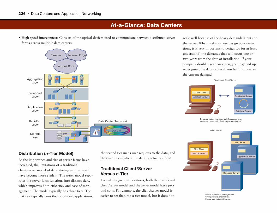
226 • Data Centers and Application Networking
• High-speed interconnect: Consists of the optical devices used to communicate between distributed server
farms across multiple data centers.scale well because of the heavy demands it puts on
the server. When making these design considera-
tions, is it very important to design for (or at least
understand) the demands that will occur one or
two years from the date of installation. If your
company doubles year over year, you may end up
redesigning the data center if you build it to serve
the current demand.
Distribution (n-Tier Model)As the importance and size of server farms have
increased, the limitations of a traditional
client/server model of data storage and retrieval
have become more evident. The n-tier model sepa-
rates the server farm functions into distinct tiers,
which improves both efficiency and ease of man-
agement. The model typically has three tiers. The
first tier typically runs the user-facing applications,
At-a-Glance: Data Centers
AggregationLayer
Front-EndLayer
ApplicationLayer
Back-EndLayer
StorageLayer
Data Center Transport
DWDMFC
Campus Core
Campus Internet Edge
Application Server
Database Server
Application GUI
Thick Client
Traditional Client/Server
Requires heavy management. Processes info,and then presents it. Exchanges mostly data.
Web Browser
Thin Client
N-Tier Model
Needs little client management.Only presents information.Exchanges data and format.
Web Server
Application Server
Database Server
the second tier maps user requests to the data, and
the third tier is where the data is actually stored.
Traditional Client/Server Versus n-TierLike all design considerations, both the traditional
client/server model and the n-tier model have pros
and cons. For example, the client/server model is
easier to set than the n-tier model, but it does not
Data Centers • 227
Data Center FacilitiesThe housing of critical computing resources such
as those found in a data center typically requires
specialized facilities and trained personnel to run a
24/7 operation. The efficient, protected, and secure
operations of these business-critical systems require
consideration of and planning for the following
items:
• Power capacity
• Cooling capacity
• Cabling (raised flooring or overhead tracks)
• Temperature and humidity controls
• Fire and smoke detection systems
• Restricted access and surveillance systems
• Space planning for future scaling
Although some of these items may seem like
overkill, loss of data can actually cause a business to
fail, so protecting the data and the equipment that
store and transport it must never be shortchanged.
Storage MethodsStorage services include both the consolidation of
information and the methods of connectivity. The
basics of storage services are explained here.
Storage methods include Network Attached Storage
(NAS), which uses specialized file servers to connect
storage devices to a network, and Storage Area
Networks (SAN), which are independent networks
designed to connect storage devices.
Security ServicesGiven the importance of the data center, security
plans should encompass all services and all devices
supporting those services. The security features
include access control lists (ACL), firewalls,
Intrusion Detection Systems (IDS), and
Authentication, Authorization, and Accounting
(AAA).
Putting a security plan in place for all services and
devices ensures that there are no “back doors”
into the data center.
NAS is optimized for file-based access to shared
storage over an IP network. SANs are optimized
for the efficient collection, storage, and retrieval of
raw data in the form of bits or blocks.
The primary connection method is Small
Computer Systems Interface (SCSI, pronounced
“scuzzy”), which uses a parallel bus interface to
connect to storage devices. SCSI commands can be
transported over fiber (optical) or IP (referred to
as ISCSI).
A newer connection method called Serial
Advanced Technology Attachment (SATA) is now
making inroads because of its high connection
speed (3 Gbps). As a side note, the older methods
have been retroactively classified as Parallel ATA
(PATA).
Data Center ManagementManagement services typically are overlaid on top
of all other services. Every layer of the data center
model requires its own set of management consid-
erations but must be supported by different orga-
nizational entities or even by distinct functional
groups within the enterprise.
Specific management categories include configura-
tion management, fault management, performance
management, security management, and account-
ing management. Each of these categories must be
included in the planning of the management services.
At-a-Glance: Data Centers
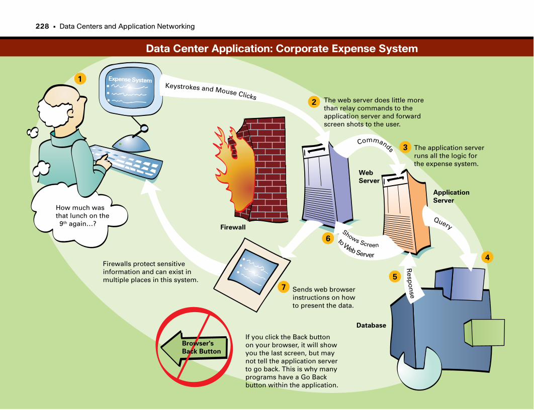
How much wasthat lunch on the 9th again…?
Expense System
Firewall
Web
Server
Application
Server
Database
Browser's
Back Button
Firewalls protect sensitiveinformation and can exist inmultiple places in this system.
The web server does little morethan relay commands to the application server and forward screen shots to the user.
The application serverruns all the logic for the expense system.
Keystrokes and Mouse Clicks
Commands
Query
Resp
on
se
Shows Screen
toWeb Server
1
2
3
4
5
6
7 Sends web browser instructions on how to present the data.
If you click the Back buttonon your browser, it will showyou the last screen, but maynot tell the application serverto go back. This is why manyprograms have a Go Backbutton within the application.
Data Center Application: Corporate Expense System
228 • Data Centers and Application Networking

This page intentionally left blank

Storage Area Networks
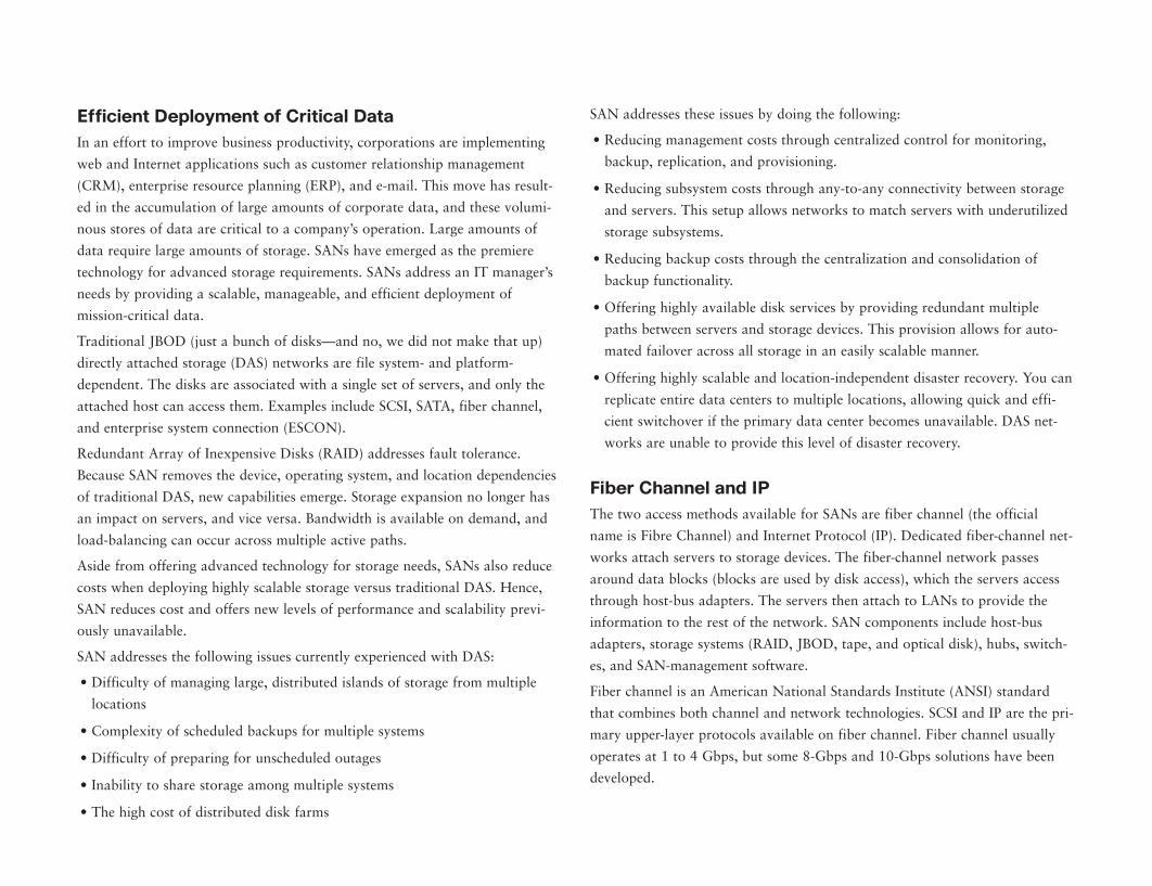
Efficient Deployment of Critical DataIn an effort to improve business productivity, corporations are implementing
web and Internet applications such as customer relationship management
(CRM), enterprise resource planning (ERP), and e-mail. This move has result-
ed in the accumulation of large amounts of corporate data, and these volumi-
nous stores of data are critical to a company’s operation. Large amounts of
data require large amounts of storage. SANs have emerged as the premiere
technology for advanced storage requirements. SANs address an IT manager’s
needs by providing a scalable, manageable, and efficient deployment of
mission-critical data.
Traditional JBOD (just a bunch of disks—and no, we did not make that up)
directly attached storage (DAS) networks are file system- and platform-
dependent. The disks are associated with a single set of servers, and only the
attached host can access them. Examples include SCSI, SATA, fiber channel,
and enterprise system connection (ESCON).
Redundant Array of Inexpensive Disks (RAID) addresses fault tolerance.
Because SAN removes the device, operating system, and location dependencies
of traditional DAS, new capabilities emerge. Storage expansion no longer has
an impact on servers, and vice versa. Bandwidth is available on demand, and
load-balancing can occur across multiple active paths.
Aside from offering advanced technology for storage needs, SANs also reduce
costs when deploying highly scalable storage versus traditional DAS. Hence,
SAN reduces cost and offers new levels of performance and scalability previ-
ously unavailable.
SAN addresses the following issues currently experienced with DAS:
• Difficulty of managing large, distributed islands of storage from multiple
locations
• Complexity of scheduled backups for multiple systems
• Difficulty of preparing for unscheduled outages
• Inability to share storage among multiple systems
• The high cost of distributed disk farms
SAN addresses these issues by doing the following:
• Reducing management costs through centralized control for monitoring,
backup, replication, and provisioning.
• Reducing subsystem costs through any-to-any connectivity between storage
and servers. This setup allows networks to match servers with underutilized
storage subsystems.
• Reducing backup costs through the centralization and consolidation of
backup functionality.
• Offering highly available disk services by providing redundant multiple
paths between servers and storage devices. This provision allows for auto-
mated failover across all storage in an easily scalable manner.
• Offering highly scalable and location-independent disaster recovery. You can
replicate entire data centers to multiple locations, allowing quick and effi-
cient switchover if the primary data center becomes unavailable. DAS net-
works are unable to provide this level of disaster recovery.
Fiber Channel and IPThe two access methods available for SANs are fiber channel (the official
name is Fibre Channel) and Internet Protocol (IP). Dedicated fiber-channel net-
works attach servers to storage devices. The fiber-channel network passes
around data blocks (blocks are used by disk access), which the servers access
through host-bus adapters. The servers then attach to LANs to provide the
information to the rest of the network. SAN components include host-bus
adapters, storage systems (RAID, JBOD, tape, and optical disk), hubs, switch-
es, and SAN-management software.
Fiber channel is an American National Standards Institute (ANSI) standard
that combines both channel and network technologies. SCSI and IP are the pri-
mary upper-layer protocols available on fiber channel. Fiber channel usually
operates at 1 to 4 Gbps, but some 8-Gbps and 10-Gbps solutions have been
developed.
232 • Data Centers and Application Networking
You can use several topologies for fiber-channel deployment:
• Point-to-point: Dedicated connections between a server and storage device.
This method is suitable when storage devices are dedicated to a single file
server.
• Arbitrated loop: Storage and file servers connect to each other in a closed
loop with up to 126 nodes. Maximum bandwidth is 100 MB shared
between all the nodes. Therefore, the number of attached nodes directly
affects the loop’s performance.
• Switch fabric: As with Ethernet, performance and reliability vastly improve
when moving from shared media (such as an arbitrated loop) to switched
fabrics. A fiber-channel switch offers up to 100 Mbps to each switched port.
You can trunk switches together to attach up to a theoretical 16 million
nodes.
The other access method to fiber channel is IP. Because SANs connect to IP
networks, the storage can be accessed across LANs, WANs, metropolitan-area
networks (MAN), and the Internet. You can manage the devices using Simple
Network Management Protocol (SNMP) and operate in a secure mode with
the use of Internet Protocol Security (IPsec), firewalls, and virtual local-area
networks (VLAN). Storage devices can connect to Ethernet devices. 10-Gbps
Ethernet is an increasingly popular SNA option.
Whereas fiber channel separates disk-block-based traffic from the rest of the
network, IP-based SAN tunnels block traffic through the IP network using the
ISCSI protocol. ISCSI uses Transmission Control Protocol (TCP) as its trans-
port. Fiber Channel over IP (FCIP) is another technology that allows fiber-
channel networks to connect to each other over LANs, MANs, and WANs.
FCIP uses TCP to tunnel fiber-channel block traffic across the IP network.
InfinibandSome specialized data center applications require extremely low-latency con-
nections between application servers and storage devices. Examples include
high-performance computing arrays used for geological exploratory modeling,
and high-performance trading environments, in which delays in financial or
stock trades of even a few milliseconds can cost thousands or millions of dol-
lars.
Infiniband is one data center technology targeted at such high-performance,
low-latency applications. In addition to low latency, Infiniband links support
bandwidth of 2 to 8 Gbps. Data center technology is evolving every day, and
more technologies in this area will undoubtedly appear on the market in the
coming years.
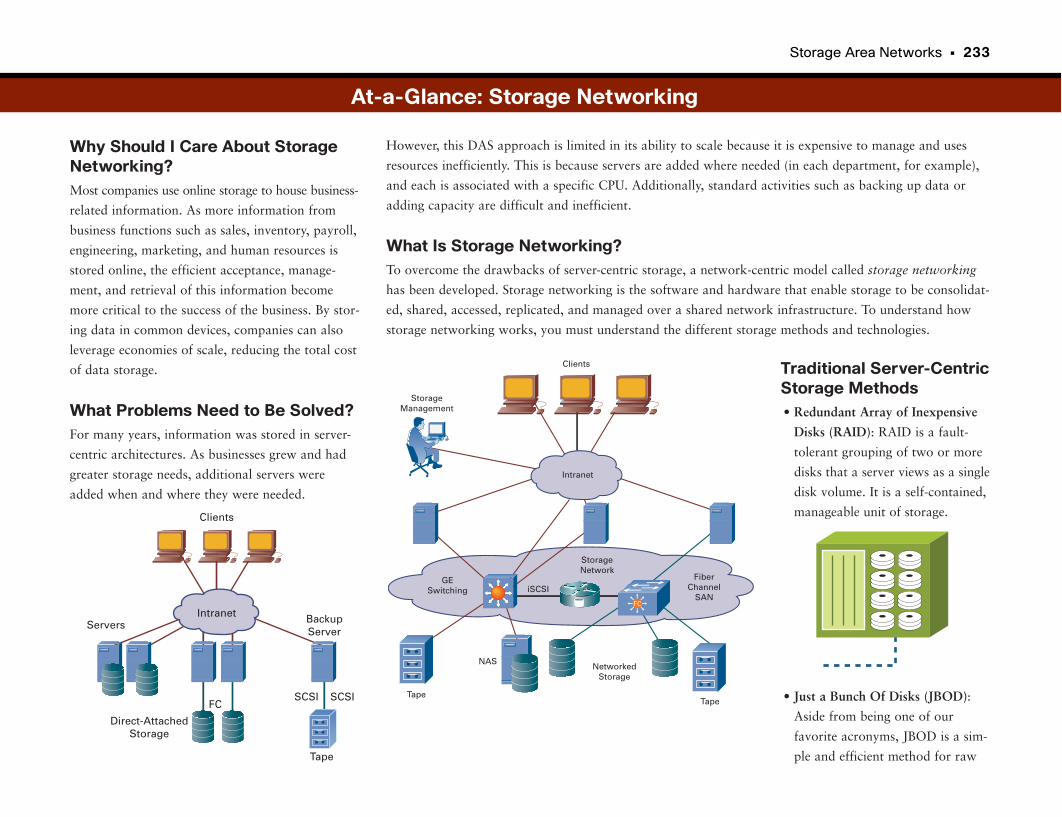
Storage Area Networks • 233
Why Should I Care About StorageNetworking?Most companies use online storage to house business-
related information. As more information from
business functions such as sales, inventory, payroll,
engineering, marketing, and human resources is
stored online, the efficient acceptance, manage-
ment, and retrieval of this information become
more critical to the success of the business. By stor-
ing data in common devices, companies can also
leverage economies of scale, reducing the total cost
of data storage.
What Problems Need to Be Solved?For many years, information was stored in server-
centric architectures. As businesses grew and had
greater storage needs, additional servers were
added when and where they were needed.
Traditional Server-CentricStorage Methods• Redundant Array of Inexpensive
Disks (RAID): RAID is a fault-
tolerant grouping of two or more
disks that a server views as a single
disk volume. It is a self-contained,
manageable unit of storage.
• Just a Bunch Of Disks (JBOD):
Aside from being one of our
favorite acronyms, JBOD is a sim-
ple and efficient method for raw
However, this DAS approach is limited in its ability to scale because it is expensive to manage and uses
resources inefficiently. This is because servers are added where needed (in each department, for example),
and each is associated with a specific CPU. Additionally, standard activities such as backing up data or
adding capacity are difficult and inefficient.
What Is Storage Networking?To overcome the drawbacks of server-centric storage, a network-centric model called storage networking
has been developed. Storage networking is the software and hardware that enable storage to be consolidat-
ed, shared, accessed, replicated, and managed over a shared network infrastructure. To understand how
storage networking works, you must understand the different storage methods and technologies.
Direct-AttachedStorage
Servers BackupServer
Clients
FCSCSI SCSI
Tape
Intranet
At-a-Glance: Storage Networking
Tape
Clients
Tape
StorageManagement
NetworkedStorage
GESwitching
StorageNetwork
FiberChannel
SANiSCSI
Intranet
NAS
FC
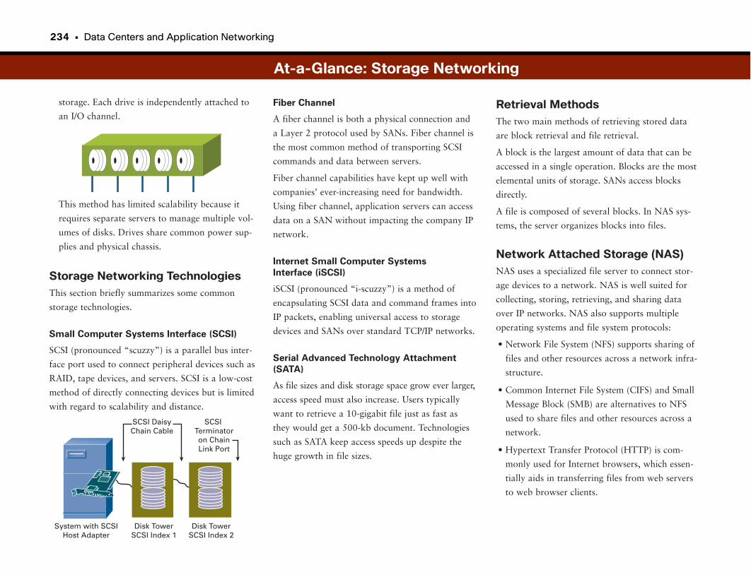
234 • Data Centers and Application Networking
storage. Each drive is independently attached to
an I/O channel.
This method has limited scalability because it
requires separate servers to manage multiple vol-
umes of disks. Drives share common power sup-
plies and physical chassis.
Storage Networking TechnologiesThis section briefly summarizes some common
storage technologies.
Small Computer Systems Interface (SCSI)
SCSI (pronounced “scuzzy”) is a parallel bus inter-
face port used to connect peripheral devices such as
RAID, tape devices, and servers. SCSI is a low-cost
method of directly connecting devices but is limited
with regard to scalability and distance.
Retrieval MethodsThe two main methods of retrieving stored data
are block retrieval and file retrieval.
A block is the largest amount of data that can be
accessed in a single operation. Blocks are the most
elemental units of storage. SANs access blocks
directly.
A file is composed of several blocks. In NAS sys-
tems, the server organizes blocks into files.
Network Attached Storage (NAS)NAS uses a specialized file server to connect stor-
age devices to a network. NAS is well suited for
collecting, storing, retrieving, and sharing data
over IP networks. NAS also supports multiple
operating systems and file system protocols:
• Network File System (NFS) supports sharing of
files and other resources across a network infra-
structure.
• Common Internet File System (CIFS) and Small
Message Block (SMB) are alternatives to NFS
used to share files and other resources across a
network.
• Hypertext Transfer Protocol (HTTP) is com-
monly used for Internet browsers, which essen-
tially aids in transferring files from web servers
to web browser clients.
Fiber Channel
A fiber channel is both a physical connection and
a Layer 2 protocol used by SANs. Fiber channel is
the most common method of transporting SCSI
commands and data between servers.
Fiber channel capabilities have kept up well with
companies’ ever-increasing need for bandwidth.
Using fiber channel, application servers can access
data on a SAN without impacting the company IP
network.
Internet Small Computer Systems
Interface (iSCSI)
iSCSI (pronounced “i-scuzzy”) is a method of
encapsulating SCSI data and command frames into
IP packets, enabling universal access to storage
devices and SANs over standard TCP/IP networks.
Serial Advanced Technology Attachment
(SATA)
As file sizes and disk storage space grow ever larger,
access speed must also increase. Users typically
want to retrieve a 10-gigabit file just as fast as
they would get a 500-kb document. Technologies
such as SATA keep access speeds up despite the
huge growth in file sizes.
At-a-Glance: Storage Networking
System with SCSIHost Adapter
Disk TowerSCSI Index 1
Disk TowerSCSI Index 2
SCSITerminatoron ChainLink Port
SCSI DaisyChain Cable
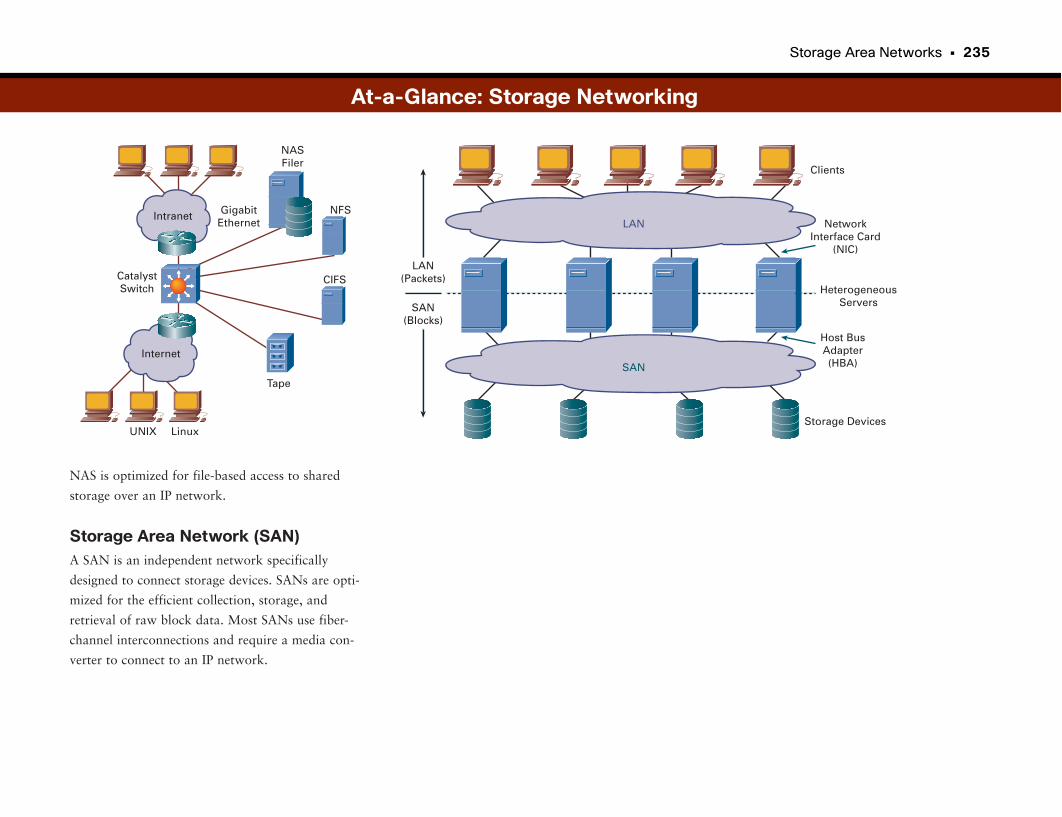
Storage Area Networks • 235
NAS is optimized for file-based access to shared
storage over an IP network.
Storage Area Network (SAN)A SAN is an independent network specifically
designed to connect storage devices. SANs are opti-
mized for the efficient collection, storage, and
retrieval of raw block data. Most SANs use fiber-
channel interconnections and require a media con-
verter to connect to an IP network.
LAN(Packets)
SAN(Blocks)
Storage Devices
Host BusAdapter(HBA)
NetworkInterface Card
(NIC)
Clients
HeterogeneousServers
LAN
SAN
At-a-Glance: Storage Networking
GigabitEthernet
NASFiler
NFS
CIFS
Tape
Internet
UNIX Linux
CatalystSwitch
Intranet
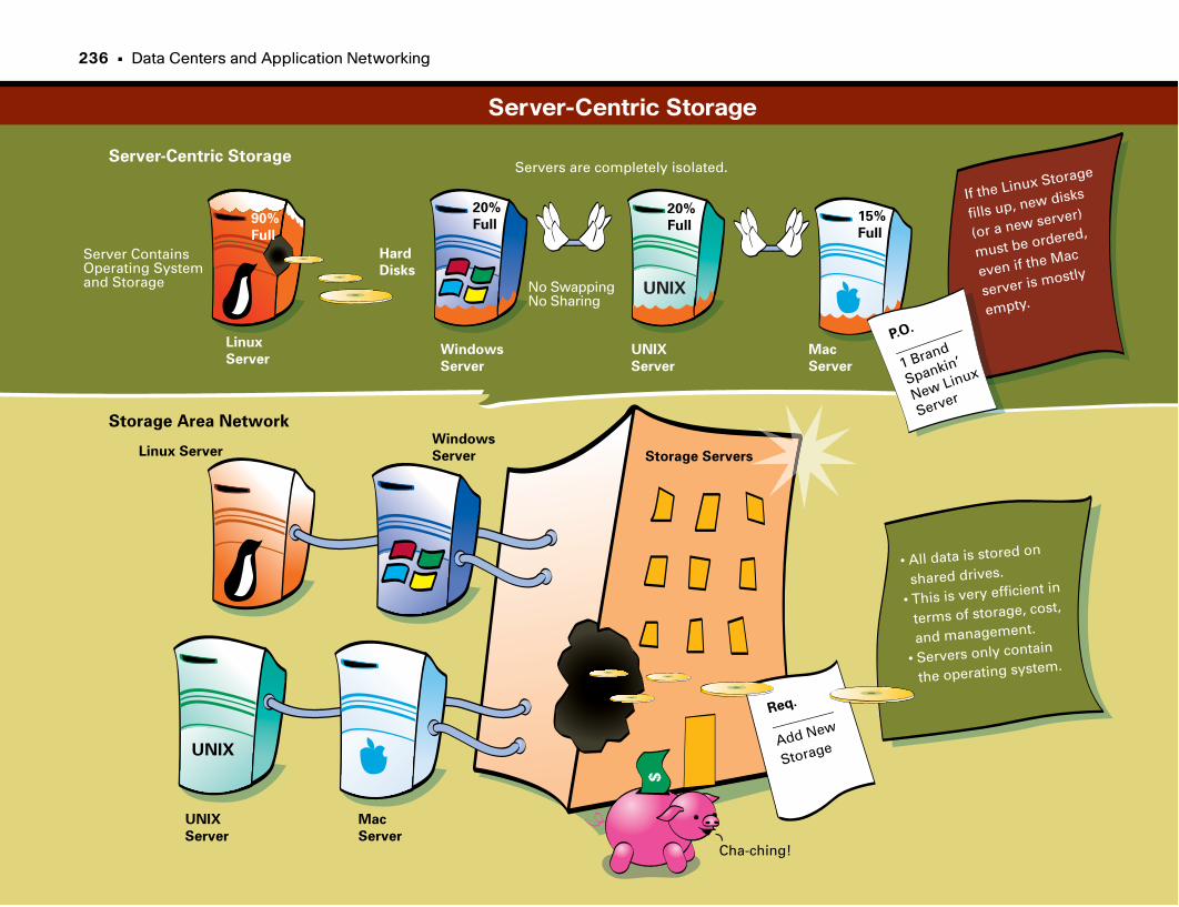
Hard
Disks
Linux
Server
Linux Server
Windows
Server
Windows
Server
UNIX
Server
UNIX
Server
Mac
Server
Mac
Server
UNIX
UNIX
P.O.
__________
1 Brand
Spankin’
New Linux
Server
Server ContainsOperating Systemand Storage
Servers are completely isolated.
No SwappingNo Sharing
If the Linux Storage
fills up, new disks
(or a new server)
must be ordered,
even if the Mac
server is mostly
empty.
20%
Full90%
Full
20%
Full15%
Full
• All data is stored on
shared drives.
• This is very efficient in
terms of storage, cost,
and management.
• Servers only contain
the operating system.
Storage Servers
Req.
_________
Add New
Storage
$
Cha-ching!
Server-Centric Storage
Storage Area Network
Server-Centric Storage
236 • Data Centers and Application Networking

This page intentionally left blank
Caching
Moving Content Close to the UserSince the 1990s, the World Wide Web has taken off as fast as air conditioning.
The Internet boom has created challenges for network engineers, including
congestion, inconsistent quality and reliability, and cost-efficient scalability.
Examples of these problems include the following:
• Not being able to access a news website during a huge news event because
the web servers are unable to handle the enormous number of simultaneous
users
• Trying to view web pages located in another country
• A company with international presence trying to localize its web pages for
each country
Network caching provides a means to localize network content closer to the
requester. Caching addresses the preceding problems by accelerating content
delivery and optimizing WAN link utilization. In other words, it moves the
content closer to the user. Examples of cacheable content include web pages,
audio files, and streaming video.
How Caching WorksCaching works in cooperation with specific choke points in a network. You
can localize traffic by strategically placing caching devices in a network.
Network caches transparently store frequently accessed content on hard
drives, intercept requests for that stored content, and present the page to the
user. Thus, the request never makes it to the intended destination, saving band-
width and server resources. Caching is also often implemented on proxy
servers of a corporate network. A proxy server is a web server that is a mirror
or copy of the main server, located closer to a user or community than the
main server.
An example of caching follows:
1. A user enters a URL in her browser.
2. A network device (such as a switch) analyzes the request. If the request
meets certain criteria, the network transparently redirects it to a local net-
work caching device.
3. Upon receipt of the request, the caching device determines whether it has
the requested content stored locally. If it doesn’t, the caching device makes
its own request to the original web server.
4. After the original web server returns the content, the cache server stores the
content on its hard disk and returns the content to the original requester.
The material is now cached locally.
5. Later, if another user requests the same web page, the cache intercepts the
request and responds by returning the locally stored copy, never communi-
cating with the original web server.
6. Because the request was fulfilled locally, the user perceives a fast response
time (which is good). Also, the request never leaves the local network,
thereby saving WAN and Internet costs and reducing the load on the desti-
nation web server.
A cache server can provide its effectiveness to multiple locations. One place is
at a company’s main access point to the Internet. You can reroute all out-
bound requests to the local cache, thereby saving Internet access fees and pro-
viding quicker responses for frequently requested pages. Another location is at
branch sites, such as at a chain store, remote sales office, or bank branch. By
caching content locally, the network can conserve WAN bandwidth for more
mission-critical applications.
Caching More Than Web PagesThe initial benefits of caching were realized with static web content. However,
video and audio files are also appropriate candidates for caching. One exam-
ple is a CEO’s address to the company. You can broadcast the address live and
then store it as video on demand for people to watch when they have time.
You can push the broadcast to local caching servers so that an employee in
another country can watch the video without having it stream from the loca-
tion of the original video. To the overseas employee, the performance is fast,
because the content is local. Additionally, as other employees overseas watch
the video, the WAN link back to the origin is unaffected.
240 • Data Centers and Application Networking
Storage Caching: From Disk to MemoryAnother method of caching uses storage caching appliances that bring data
“closer” to the user and improve performance via large memory caches for
database data.
Issues Affecting CachingDuring a sudden surge of web traffic, a caching device can become overloaded,
no longer able to handle additional web requests. To solve this problem, cache
engines determine when they reach a particular load limit. At the point of
overload, the cache device refuses additional requests and forwards subsequent
requests directly to the destination web server to handle directly.
After the cache device can process the backlog of requests, it intercepts
requests again. Another issue is keeping the cached content current. The cache
device becomes less effective if it can’t show the same content as if the user vis-
ited the web server directly. An example might be a stock-tracking page: What
good is the caching device if the stock price is an hour or day old compared to
the actual website?
You have three different ways to indicate whether content can be cached and
how long it can be cached. The first method is in the actual HTTP document.
HTTP can specify whether a document is cacheable. Additionally, with HTTP
1.1, the web page author can specify the expiration time for a particular page.
HTTP 1.1 also allows a caching device to send small requests to the source
web server so that it can determine whether content has changed.
The second method of ensuring content freshness is by configuring the caching
device. You can configure the cache device to “expire” pages at a certain rate,
at which the cache device makes requests to the source web servers for updates
to the pages.
The final method to ensure content freshness is through the user’s configura-
tion of his browser. A user can ensure fresh content by clicking the Reload/
Refresh button. Browsers by default cache web content locally, and you can
configure them to do no caching either explicitly or using the Shift-Reload/
Shift-Refresh method. Newer methods of intelligent caching store the rendering
of the page and fetch only the updated content from the server. This method
balances the advantages of caching with the need to have current data.
Caching
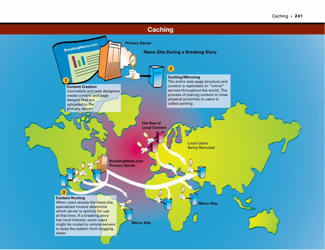
Caching • 241
BreakingNews.com
News Site During a Breaking Story
Caching/Mirroring
The entire web-page structure andcontent is replicated on ”mirror“ servers throughout the world. Theprocess of placing content in closephysical proximity to users is called caching.
Content Creation
Journalists and web designerscreate content and pagedesigns that areuploaded to theprimary server.
Primary Server
BreakingNews.com
Primary Server
Hot Bed of
Local Content
1
3
Local Users Being Rerouted
Content Routing
When users access the news site, specialized routers determinewhich server is optimal for use at that time. If a breaking story has local interest, some users might be routed to remote servers to keep the system from boggingdown.
2
Mirror Site
Mirror Site
Caching
Wide Area File Services
Branch Offices RuleOnce upon a time, the corporate headquarters was king, with the majority of
employees who worked for the company going to work at the headquarters. In
the service economy, companies needed geographic coverage and local offices
near their customers, which fueled an explosion of branch offices.
A branch office can be anything from a gas station or convenience store, to a
retail store in a shopping mall, to a stock-trading location, to your local bank
branch.
Branch offices are everywhere. Just like in the headquarters location, applica-
tions that run in the data center have file storage requirements are also
required in branch offices. So there has also been an explosion in local file
servers in branch office locations.
The difficulty is that branch offices rarely have the IT staff to manage file
servers, leading to either additional costs or poorly managed servers.
Centralizing StorageCentralizing storage in the headquarters data center is strongly preferred,
instead of having a myriad of distributed file servers in far-flung branch
offices. This greatly simplifies operations, including backups and disaster
recovery planning, as well as regulatory compliance issues. Companies only
need a team of central IT staff administering the file servers in the central
data center.
The trick is how to have central file servers being used by employees in branch
offices over a WAN without impacting application performance. The WAN,
because of its limited bandwidth and relatively longer latencies than a LAN,
inherently slows down file access (to a grinding halt if we are not careful).
Enter Wide Area File Services (WAFS)The answer is to introduce a technology that can make the WAN seem like a
LAN from a file services point of view—and this is the essence of Wide Area
File Services (WAFS). With WAFS, branch office employees can use applica-
tions that rely on file servers that reside in a distant location—back in the cor-
porate headquarters data center—and not notice any degradation of file access
speeds.
244 • Data Centers and Application Networking
Why Should I Care About Wide AreaFile Services?The traditional model of heavily centralized busi-
nesses has quickly evolved into a more distributed
model, giving businesses geographic coverage and
agility.
Estimates are that 40 to 60 percent of employees
work at non-headquarters sites, making it increas-
ingly critical for workers at branch offices to have
access to the same services, applications, and infor-
mation as those working at the central headquarters.
One of the more significant costs of providing
applications and services at branch locations are
the file systems. Distributed file servers at each
branch location create a number of operational
issues:
• Remote management of the file servers
• Data replication and disaster recovery
• Avoiding productivity losses in the event of a
file server failure
• Consuming critical WAN bandwidth and
resources by moving files back and forth and to
and from the corporate headquarters
WAFS provides the means to give branch employ-
ees the tools they need without creating the opera-
tional issues just noted.
What Problems Need to Be Solved?The object of a WAFS is to provide a virtualized
file server system, in which applications run in the
How Cisco WAFS WorksThe Cisco WAFS solution consolidates file servers
in the data center at the corporate headquarters
site. Branch office applications communicate with
an edge file engine (FE), which provides transpar-
ent access to file servers in the data center as if they
were local to the branch office LAN. The WAFS
FE normally is a dedicated hardware appliance
installed at headquarters and the branch office(s).
The FE also optimizes file service accesses, reducing
“chatty” protocols to the essential communication
across the WAN to conserve bandwidth utilization
and preserve application performance.
branch office as if the file servers were local. After
this is accomplished, these files must be transported
across the WAN intelligently to conserve critical
bandwidth resources. There must also be a means to
centralize file systems at the corporate headquarters
without compromising application performance. In
addition to the optimization challenges, government
and industry regulations—including Sarbanes-Oxley,
HIPAA, PCI, and other similar data management
and security mandates—must be adhered to.
At-a-Glance: Wide Area File Services
Wide AreaNetwork
“Islands of Storage”
Backup
ITBranch Office
Data Center
NASDAS
Files
IT
NASSAN
Files
Backup
ITRegional Office
NASDAS
Files
Backup
ITRemote Office
NASDAS
Files
Wide Area File Services • 245
After the FE is deployed, IT staff can provide
appropriate management, backups, and disaster
recovery for all file servers centrally in the head-
quarters data center, reducing risk exposure. The
FE does not change the application. It operates at
the transport protocol layer (Layer 4) rather than
at the application layer (Layer 7).
Ensuring TransparencyWAFS transparency is important, because it ensures
that applications run without disruption. In the
data center, the Core FE provides a transparent
interface (Server FE) so that file services “believe”
they are communicating directly with clients.
Similarly, in the branch office, the Edge FE pro-
vides a transparent interface (Client FE) so that
clients believe they are communicating directly
with file services. The Core FE and Edge FE use a
proprietary transport protocol, which is optimized
to provide high application-to-server performance
while being transparent in the implementation.
CachingCaching is the process of preloading information
that is likely to be used, in close proximity to
where it will be used. Intelligent caching is critical
to achieving the performance required by today’s
high-end business applications. Cisco WAFS pro-
vides caching locally for files being used or modi-
fied by the branch office. With data read caching,
when a user opens a file, a copy is stored on the
local appliance. From then on, with each request,
the Cisco FE checks to see if the data has changed.
At-a-Glance: Wide Area File Services
Wide AreaNetwork
Branch Office
Data Center
ITAdministration
Cluster
NASSAN
Regional Office
Remote OfficeCore FE
FilesEdge FEEdge FE
Edge FE
Files
Files
Files
Wide Area File Services
Wide AreaNetwork
Data Center
CIFS
NFS
ManagementAgent
RequestHandler
CIF
S/N
FS
Client
Transport
FileEngine
NAS
CoreFE
WindowsFile Server
StorageArray
Unix/LinuxFile Server
SA
N
LAN
Branch Office
ManagementAgent
RequestHandler
CIF
S/N
FS
Server
Transport
FileEngine
LAN
WindowsClient
Unix/LinuxClient
Edge FE
Metadata
DataCache
Server-FE FE-FE Client-FE
File System Transparency
246 • Data Centers and Application Networking
If it has not, the data is served as a local request
with LAN-like performance.
This setup not only helps minimize the amount of
bandwidth consumed when files are accessed, but
it also helps ensure that a stale file is never served.
At-a-Glance: Wide Area File Services
Wide AreaNetwork
CIFSNFS
CIFSNFS
Centralized StorageManagement
Backup
LAN
Branch Office
Remote OfficeData Center
File A
File A
CIFSNFS
LAN
File A
NASSAN
File Caching

This page intentionally left blank

Wide Area Application Services
Centralizing ApplicationsFor all the reasons we want to centralize storage, it is also highly desirable to
centralize application servers.
Again, the trick is how to have central application servers being used by
employees in branch offices over a WAN without impacting application per-
formance. The WAN, because of its limited bandwidth and relatively longer
latencies than a LAN, inherently slows down applications (to a grinding halt if
we are not careful).
Because most employees at a typical company now work in branch offices, it is
highly preferable that those employees be as productive as those working at
the corporate headquarters. To do so, they must have access to the same appli-
cations and have near-LAN performance with those applications as well.
Enter Wide Area Application Services (WAAS)The answer is to introduce a technology that can make the WAN seem like a
LAN from an application point of view. This is the essence of Wide Area
Application Services (WAAS). With WAAS, branch office employees can use
application servers that reside in a distant location—back in the corporate
headquarters data center—and not notice any degradation of application per-
formance.
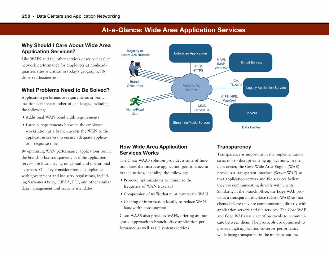
250 • Data Centers and Application Networking
Why Should I Care About Wide AreaApplication Services?Like WAFS and the other services described earlier,
network performance for employees at nonhead-
quarters sites is critical in today’s geographically
dispersed businesses.
What Problems Need to Be Solved?Application performance requirements at branch
locations create a number of challenges, including
the following:
• Additional WAN bandwidth requirements
• Latency requirements between the employee
workstation at a branch across the WAN to the
application servers to ensure adequate applica-
tion response time
By optimizing WAN performance, applications run in
the branch office transparently as if the application
servers are local, saving on capital and operational
expenses. One key consideration is compliance
with government and industry regulations, includ-
ing Sarbanes-Oxley, HIPAA, PCI, and other similar
data management and security mandates.
At-a-Glance: Wide Area Application Services
Enterprise Applications
WAN, VPN,Internet
Majority of Users Are Remote
Data Center
BranchOffice User
MMS,RTSP/RTP
HTTP,HTTPS
MAPI,IMAP,
WebDAV
ICA,TN3270
CIFS, NFS,WebDAV
Home/RoadUser
Streaming Media Servers
E-mail Servers
Servers
Legacy Application Servers
How Wide Area ApplicationServices WorksThe Cisco WAAS solution provides a suite of func-
tionalities that increase application performance in
branch offices, including the following:
• Protocol optimizations to minimize the
frequency of WAN traversal
• Compression of traffic that must traverse the WAN
• Caching of information locally to reduce WAN
bandwidth consumption
Cisco WAAS also provides WAFS, offering an inte-
grated approach to branch office application per-
formance as well as file systems services.
TransparencyTransparency is important in the implementation
so as not to disrupt existing applications. In the
data center, the Core Wide Area Engine (WAE)
provides a transparent interface (Server-WAE) so
that application servers and file services believe
they are communicating directly with clients.
Similarly, in the branch office, the Edge WAE pro-
vides a transparent interface (Client-WAE) so that
clients believe they are communicating directly with
application servers and file services. The Core WAE
and Edge WAEs use a set of protocols to communi-
cate between them. The protocols are optimized to
provide high application-to-server performance
while being transparent in the implementation.
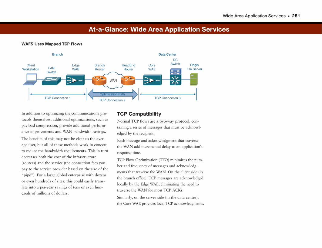
Wide Area Application Services • 251
In addition to optimizing the communications pro-
tocols themselves, additional optimizations, such as
payload compression, provide additional perform-
ance improvements and WAN bandwidth savings.
The benefits of this may not be clear to the aver-
age user, but all of these methods work in concert
to reduce the bandwidth requirements. This in turn
decreases both the cost of the infrastructure
(routers) and the service (the connection fees you
pay to the service provider based on the size of the
“pipe”). For a large global enterprise with dozens
or even hundreds of sites, this could easily trans-
late into a per-year savings of tens or even hun-
dreds of millions of dollars.
ClientWorkstation LAN
Switch
DCSwitch Origin
File Server
Optimization Path
TCP Connection 2TCP Connection 1
WAN
BranchRouter
HeadEndRouter
EdgeWAE
CoreWAE
TCP Connection 3
Branch Data Center
At-a-Glance: Wide Area Application Services
WAFS Uses Mapped TCP Flows
TCP CompatibilityNormal TCP flows are a two-way protocol, con-
taining a series of messages that must be acknowl-
edged by the recipient.
Each message and acknowledgment that traverse
the WAN add incremental delay to an application’s
response time.
TCP Flow Optimization (TFO) minimizes the num-
ber and frequency of messages and acknowledg-
ments that traverse the WAN. On the client side (in
the branch office), TCP messages are acknowledged
locally by the Edge WAE, eliminating the need to
traverse the WAN for most TCP ACKs.
Similarly, on the server side (in the data center),
the Core WAE provides local TCP acknowledgments.
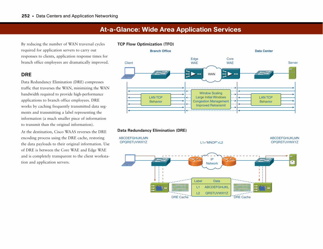
252 • Data Centers and Application Networking
By reducing the number of WAN traversal cycles
required for application servers to carry out
responses to clients, application response times for
branch office employees are dramatically improved.
DREData Redundancy Elimination (DRE) compresses
traffic that traverses the WAN, minimizing the WAN
bandwidth required to provide high-performance
applications to branch office employees. DRE
works by caching frequently transmitted data seg-
ments and transmitting a label representing the
information (a much smaller piece of information
to transmit than the original information).
At the destination, Cisco WAAS reverses the DRE
encoding process using the DRE cache, restoring
the data payloads to their original information. Use
of DRE is between the Core WAE and Edge WAE
and is completely transparent to the client worksta-
tion and application servers.
At-a-Glance: Wide Area Application Services
WAN
Client
Branch Office Data Center
ServerEdgeWAE
CoreWAE
LAN TCPBehavior
LAN TCPBehavior
Window ScalingLarge Initial Windows
Congestion ManagementImproved Retransmit
IPNetwork
L1+“MNOP”+L2
DRE Cache DRE Cache
ABCDEFGHIJKLMNOPQRSTUVWXYZ
ABCDEFGHIJKLMNOPQRSTUVWXYZ
Label
L1
L2
Data
ABCDEFGHIJKL
QRSTUVWXYZ
TCP Flow Optimization (TFO)
Data Redundancy Elimination (DRE)

This page intentionally left blank

Part VII
Unified Communications
Communication on the Data Network
Not too long ago there was a single “network” called the
public switched telephone network (PSTN). Of course, this
is the worldwide phone system, and for a very long time it
was the world’s biggest network. Somewhere along the
line, some smart people figured out that by using different
frequencies to represent 1s and 0s, computers could com-
municate. As soon as this technology became popular, the
speeds were too slow for big data transfers, so a “data-
only” network was created. Then some smart people came
along and figured out how to turn the human voice into 1s
and 0s, and voilà—we have voice on the data network.
It turns out that is it much easier to put voice on a data
network than the other way around. While we are at it,
why not throw live video streams on it, too? Over the
past several years, not only has there been a big migra-
tion to put voice, video, and data on a single digital net-
work (called convergence), but also to use some of the
“intelligence” of the network and applications to
improve the reach and effectiveness of voice and video.
This section focuses on how these communication tools
work on the network.
We start with a focus on the basics of using the data net-
work to make phone calls. This section looks at how
voice over Internet Protocol (IP) or Unified
Communications works. “Voice over IP” goes a bit deep-
er, explaining how the human voice (or any sound, real-
ly) is converted to a digital signal so that it can be trans-
ported over a network that can communicate with only
1s and 0s.
One of the main issues with putting voice on a data net-
work is that phone conversations happen in real time.
This means when two people speak, they typically want
Voice over IP 257
Quality of Service 269
Unified Personal 275
Communications
Meeting Collaboration Spaces 279
Traditional Videoconferencing 283
Telepresence 289
Presence and 293
Location-Aware Services
IP Call Center 297
Multicast and IPTV Broadcasts 305
to hear the words as they are being spoken rather than
having delays. The section “Quality of Service” looks at
one of the key features that makes voice calls work on
the network.
Later in this part we look at another issue that people
have today in dealing with too many devices, between
their mobile phone, desk phone, e-mail, and other tools.
“Unified Personal Communications” looks at a tool that
helps workers consolidate all these tools into a single
device. Along with that, “Meeting Collaboration Spaces”
looks at some tools that use network intelligence to
ensure that the best communication method is used for a
given situation. We look at traditional and IP-based
videoconferencing and telepresence
Sometimes people can communicate with only certain
tools, whether that’s voice, instant messaging (IM), or e-
mail, depending on where they are and what they are
doing. Sometimes you may want all your incoming calls
to go directly to voice mail unless a customer or your
spouse calls. “Presence and Location-Aware Services”
looks at some tools that make this possible.
One of the key applications of voice on the data network
is IP call centers. These systems provide one of the best
examples of how the voice and data capabilities of a sin-
gle network can be used in a business solution.
We end this part with a technology that makes mass com-
munication such as video broadcasting, media streaming,
and collaboration solutions possible. The part ends with
a discussion of IP multicast, which conserves network
bandwidth by avoiding the unnecessary duplication of
data streams destined for multiple users. Without this
technology, networks would be prone to delays or even
crashes due to excessive traffic.

Voice over IP
new levels of productivity that were not possible with traditional PSTN
telephony.
• Application integration: IP phones are incorporating extensible markup lan-
guage (XML) browsers into their video interfaces. Therefore, a company
can extend enterprise applications to employees who do not need a comput-
er. For example, retail store employees can use a web application on an IP
phone to enter their timecard.
Additionally, mobile employees can make VoIP calls using their notebook com-
puters and software-based phones. They can also retrieve their voice mail by
simply downloading their e-mail. Ultimately, the convergence of enterprise
applications with VoIP will increase productivity and efficiency in ways not
possible with traditional PBX networks.
Unifying CommunicationsUnified Communications refers to a suite of converged communications servic-
es, including voice, voice mail, audioconferencing, videoconferencing, web
conferencing, instant messaging, contact centers, and others. Convergence has
two dimensions:
• Communications services operate over the IP network using technologies
including VoIP and video over IP.
• Communications services are integrated seamlessly so that the user experi-
ence is as productive as possible.
For example, because VoIP calls are digital, voice mail can be captured as an
audio file and listened to using a computer, or even e-mailed to a recipient’s
e-mail system. An audioconference can be launched by joining digital VoIP
streams on the network and using the contact directory within the office
e-mail and calendaring software to select meeting participants.
A Unified Communications network consists of four distinct layers:
• Client layer: Actual devices a person interacts with: IP phones, IP
videoconferencing equipment, software-based phones, laptop computers,
handheld computers, and PDAs
Making Calls over the WebTraditionally, voice traffic traveled across circuit-switched connections of the
PSTN. Corporate customers often had so many phone lines that they often
deployed their own telephone exchanges using private branch exchange (PBX)
networks or networks of private lines and time-division multiplexers (TDM).
Although they had trunks into the PSTN (trunks are PSTN connections that
can carry dozens of calls), these traditional networks tended to be proprietary,
closed systems that were expensive to maintain, upgrade, and scale.
Voice over IP (VoIP) provides voice services such as phones, call routing, and
voice mail using the data network. Thus, both the data and voice networks
can converge into a single IP network, facilitating the ability to integrate
computer-based applications with phones and videoconferencing. Migrating to
a VoIP-based telephony network reduces the total cost of ownership for voice
services in the following ways:
• Toll charges: VoIP carries traffic through a corporation’s private IP network,
thereby bypassing the dedicated leased voice lines used to connect remote
offices. Eliminating the use of dedicated leased voice lines lets a company
avoid toll charges and monthly fees for these dedicated circuits and converge
its voice traffic onto the data network it is already paying for.
• Administration costs: Because VoIP shares the same network as data appli-
cations, you have only one network to manage. Traditionally, separate
duplicate teams managed the voice network and the data network. There is
also large savings in not having to run new cables for new lines or other
changes.
• Employee mobility: Working from home or remote locations is a trend that
has demonstrated increased employee productivity. Imagine conducting busi-
ness over your work phone from home. With technologies such as virtual
private networks (VPN) and broadband services, employees can work from
home or an airport using the tools (computer and phone) they use at work
as if they were sitting at their office desks.
• Productivity: Integrating VoIP with other corporate systems, such as employee
directories, collaboration tools, e-mail, and calendaring systems, provides
258 • Unified Communications
• Infrastructure layer: Traditional devices associated with data networks:
routers, switches, and gateways
• Call-processing layer: Call control and subscriber directories
• Application layer: Voice mail, unified messaging (imagine receiving voice
mail in your e-mail box or listening to your e-mail over the phone), personal
and business productivity applications
Client LayerThe client layer consists of phones, video equipment, and software-based
phones. These are the devices people interact with. One issue that imple-
menters face when trying to convert their traditional PBX systems to IP net-
works is how to provide power to the phones. Traditional phones simply plug
a single cable into the wall for both power and voice services. Because IP
phones plug into IP networks (usually via Ethernet), traditional data networks
are unable to provide power. At first glance, an IP phone must have two
cables: a network cable and a power cable. However, the network switches
that the IP phones are connected to can supply inline power over the same
Ethernet cable (called Power over Ethernet [PoE]) as the data connectivity.
Devices at the client layer are responsible for translating the audio stream into
digital data. IP phones use digital signal processing (DSP) to “sample” the
audio received from the headset and convert it into digital data. This process is
similar to taking a photo with a digital camera.
Infrastructure LayerFrom the perspective of delivering the reliable voice services people expect on
the PSTN, the infrastructure layer is the most critical. It is the job of the infra-
structure to ensure that a call (in the form of VoIP packets) is carried from
source to destination in a reliable and timely manner.
Traditional data networks tolerate delay or some degree of packet loss because
of the nature of the applications that they were designed for, such as access to
relatively low-speed mainframe applications. However, because calls happen in
real time, calls with delayed or lost packets deliver frustrating audio to the
receiver, in which a call either becomes choppy or gets dropped. Implementing
QoS and properly provisioning a network ensures that the data network han-
dles calls in the manner traditionally associated with the PSTN.
Telephony gateways are also a critical part of the infrastructure layer. Telephony
gateways bridge the worlds of traditional TDM telephony networks to Unified
Communications networks. Gateways have several purposes:
• Bridging the PSTN to an IP network
• Connecting legacy PBXs to an IP network
• Tunneling legacy PBXs and phones to other legacy PBXs
Call-Processing LayerCallManager is the center of the call-processing layer. CallManager fills the role
of the digital switch in the PSTN or a PBX in a corporate telephone network. It
provides the connectivity, signaling, and device control and intelligence for IP
phones and gateways. In addition, CallManager performs operations, adminis-
tration, maintenance, and provisioning (OAM&P).
Cisco CallManager is responsible for establishing a call between two phones,
but after the call is established, CallManager removes itself, and the phones
talk to each other directly. The call control (ringing the phone, directing the
call, providing dial tone) is handled separately from the call’s actual content.
When someone dials a number, CallManager looks up the number, rings the
phone on the other end, and provides the ringing sound to the person who
dialed the number. When the person at the other end picks up the phone,
CallManager leaves the picture, because the two phones communicate directly.
Dial plans define the accessibility of all entities in a voice network. Dial plans
also provide alternative path routing and policy restrictions. In Unified
Voice over IP • 259
Communications, CallManager also provides Call Admission Control (CAC)
functionality. When a user places a call over an IP wide-area network (WAN)
(to or from a branch office), CallManager must determine whether enough
bandwidth is available across the slower-speed WAN. If the capacity exists,
CallManager passes the call through. If not, CallManager may attempt to pass
the call through the PSTN. The CAC and the dial plan must be tightly coupled
to ensure that calls are passed efficiently and appropriately through the net-
work. For example, a worker in one state might dial the internal five-digit
extension of a coworker in another state. If the IP WAN is filled to call capaci-
ty, the call is redirected across the PSTN.
Application LayerWith the convergence of Unified Communications and IP data networks, it is
easy to create new applications that merge the worlds of phones, video, and
computers. Examples of these applications include the following:
• The ability to use speech recognition in combination with call-handling
rules: Users can set up personalized rules that provide call forwarding and
screening on-the-fly. They can forward calls to other user-defined locations
such as their homes or cellular phones. Additionally, users can use voice
commands to receive, reply to, record, skip, and delete messages.
• The merging of voice, e-mail, and fax messaging into a single “inbox”:
Users can access their voice, e-mail, and fax messages from their IP phones,
cellular phones, or PCs (via e-mail).
• The mobility of a phone number: A user can log into any phone and have it
assume his phone number. Thus, an employee based in Greenville, South
Carolina, can travel to the company’s Wheaton, Illinois, office and use the
phone (with her Greenville phone number) as if she were home. This mobili-
ty presents issues that haven’t existed before, such as how to handle a 911
call. If you make a call to 911 from a phone in Illinois using a phone num-
ber that is based in South Carolina, how is the 911 call properly directed to
the local emergency services?
• Contact-center processing: See the later discussion on IP call centers.
• Integration of existing customer applications, such as ERP, CRM, and inven-
tory management. Users can log customer orders and enter (or even scan)
inventory or shipments directly into their VoIP phone for immediate pro-
cessing into the back-end database.
Deployment ModelsUnified Communications has four deployment models:
• Single site: Unified Communications is implemented in a single location.
• Multisite independent call processing: Unified Communications is imple-
mented in multiple remote sites, but calls between the sites travel across the
PSTN.
• Multisite with distributed call processing: Unified Communications is imple-
mented across multiple remote sites with call-processing and voice-messaging
equipment present at each location. Calls travel across the IP WAN as the
primary path, with the PSTN as a secondary path.
• Multisite with centralized call processing: Unified Communications is imple-
mented across multiple sites, with call processing and voice messaging cen-
tralized in a single location.
For large corporations, true independence from traditional PBX occurs when
they implement either a distributed or centralized call-processing model. In
both cases, the IP network is the primary path for all corporate calls, with the
PSTN serving as backup when either the IP WAN is down or it has insufficient
resources to handle calls.
The distributed model places call-processing and voice-messaging equipment at
multiple corporate locations. CallManager, voice-messaging equipment, and
other resources at each location act as a tightly coupled system with the other
locations. The distributed model works well in cases where a merger or acqui-
sition has taken place or in cases where a legacy PBX is being migrated to
VoIP over time on a branch-by-branch basis.
260 • Unified Communications
The centralized model places call-processing and voice-messaging equipment in
a central location. Remote locations contain only the basic infrastructure, such
as switches, routers, gateways, and endpoints such as IP phones. The central-
ized model may be easier to administer and troubleshoot because of a single
point to set up and manage the dial plan and endpoint provisioning, and it
may require less overall equipment.
Whether a distributed or centralized model is used depends on the company
business model and requirements. Centralized offers the lowest overhead to
manage, but it does have limitations. Distributed may require more adminis-
tration at more than one location, but it can offer some flexibility from loca-
tion to location that may be required.
For example, if a business has a large headquarters and many very small
branch offices, such as a gasoline retailer, a centralized model is advantageous.
But in the case of a very large department store retailer, a distributed model
may offer faster and easier administration.
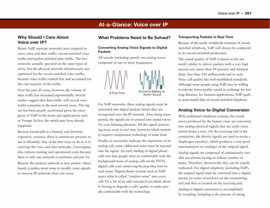
Voice over IP • 261
Why Should I Care About Voice over IP?Before VoIP, separate networks were required to
carry voice and data traffic: circuit-switched voice
traffic and packet-switched data traffic. The two
networks actually operated on the same types of
wires, but the physical network infrastructure was
optimized for the circuit-switched voice traffic,
because voice traffic existed first and accounted for
the vast majority of the traffic.
Over the past 20 years, however, the volume of
data traffic has increased exponentially. Several
studies suggest that data traffic will exceed voice
traffic sometime in the next several years. This fig-
ure has been greatly accelerated given the emer-
gence of VoIP to the home and applications such
as Vonage. In fact, the switch may have already
happened.
Because bandwidth is a limited, and therefore
expensive, resource, there is continuous pressure to
use it efficiently. One of the best ways to do so is to
converge the voice and data networks. Convergence
also reduces training and operational costs because
there is only one network to maintain and pay for.
Because the primary network is now packet- (data)
based, it makes more sense to modify voice signals
to traverse IP networks than vice versa.
Transporting Packets in Real Time
Because of the nearly worldwide existence of circuit-
switched telephony, VoIP will always be compared
to its circuit-switched predecessor.
The sound quality of VoIP is based on the net-
work’s ability to deliver packets with a very high
success rate (more than 99 percent) and minimal
delay (less than 250 milliseconds end to end).
Voice call quality has well-established standards.
Although some people using VoIP may be willing
to tolerate lower-quality sound in exchange for free
long distance, for business applications, VoIP quali-
ty must match that of circuit-switched telephony.
Analog Voice-to-Digital ConversionWith traditional telephony systems, the sound
waves produced by the human voice are converted
into analog electrical signals that are easily trans-
mitted down a wire. On the receiving end of the
connection, the electric signals are used to excite a
diaphragm (speaker), which produces a very good
representation (or analogy) of the original signal.
Analog signals are composed of continuously vari-
able waveforms having an infinite number of
states. Therefore, theoretically they can be exactly
replicated. For digital telephony (including VoIP),
the original signal must be converted into a digital
stream (or series of packets) on the transmitting
end and then re-created on the receiving end.
Analog-to-digital conversion is accomplished
by sampling. Sampling is the process of taking
What Problems Need to Be Solved?
Converting Analog Voice Signals to Digital
Packets
All sounds (including speech) are analog waves
composed of one or more frequencies.
For VoIP networks, these analog signals must be
converted into digital packets before they are
transported over the IP network. After being trans-
ported, the signals are re-created into sound waves
for your listening pleasure. All this signal process-
ing must occur in real time, however, which normal-
ly requires compression technology of some kind.
Finally, to accurately replicate the experience of an
analog call, some additional noise must be injected
into the signal. An early finding of digital phone
calls was that people were so comfortable with the
background noise of analog calls on the PSTN,
digital calls were unnerving because they had no
such noise. Digital phone systems such as VoIP
inject what is called “comfort noise” into every
call. It’s a bit of an odd concept if you think about
it: having to degrade a call’s quality to make peo-
ple comfortable with the technology.
Someone Making an"Ahhh" Sound
A Pure Tone
At-a-Glance: Voice over IP
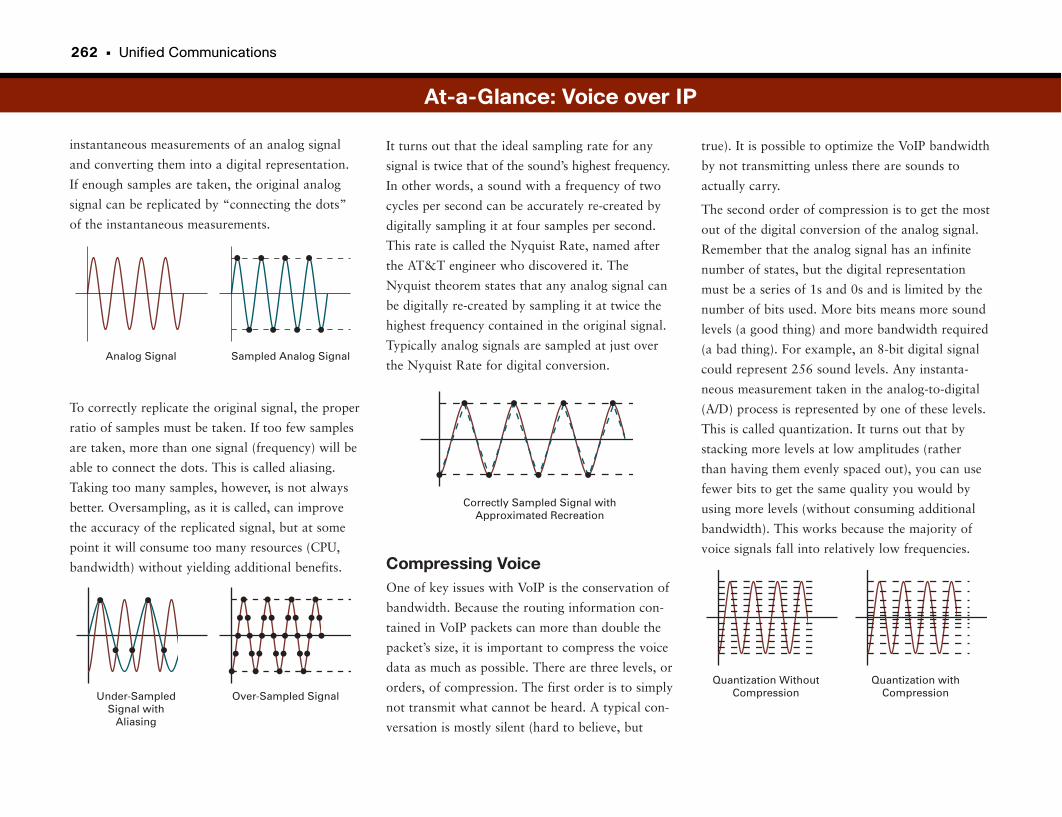
262 • Unified Communications
instantaneous measurements of an analog signal
and converting them into a digital representation.
If enough samples are taken, the original analog
signal can be replicated by “connecting the dots”
of the instantaneous measurements.
To correctly replicate the original signal, the proper
ratio of samples must be taken. If too few samples
are taken, more than one signal (frequency) will be
able to connect the dots. This is called aliasing.
Taking too many samples, however, is not always
better. Oversampling, as it is called, can improve
the accuracy of the replicated signal, but at some
point it will consume too many resources (CPU,
bandwidth) without yielding additional benefits.
true). It is possible to optimize the VoIP bandwidth
by not transmitting unless there are sounds to
actually carry.
The second order of compression is to get the most
out of the digital conversion of the analog signal.
Remember that the analog signal has an infinite
number of states, but the digital representation
must be a series of 1s and 0s and is limited by the
number of bits used. More bits means more sound
levels (a good thing) and more bandwidth required
(a bad thing). For example, an 8-bit digital signal
could represent 256 sound levels. Any instanta-
neous measurement taken in the analog-to-digital
(A/D) process is represented by one of these levels.
This is called quantization. It turns out that by
stacking more levels at low amplitudes (rather
than having them evenly spaced out), you can use
fewer bits to get the same quality you would by
using more levels (without consuming additional
bandwidth). This works because the majority of
voice signals fall into relatively low frequencies.
It turns out that the ideal sampling rate for any
signal is twice that of the sound’s highest frequency.
In other words, a sound with a frequency of two
cycles per second can be accurately re-created by
digitally sampling it at four samples per second.
This rate is called the Nyquist Rate, named after
the AT&T engineer who discovered it. The
Nyquist theorem states that any analog signal can
be digitally re-created by sampling it at twice the
highest frequency contained in the original signal.
Typically analog signals are sampled at just over
the Nyquist Rate for digital conversion.
Compressing VoiceOne of key issues with VoIP is the conservation of
bandwidth. Because the routing information con-
tained in VoIP packets can more than double the
packet’s size, it is important to compress the voice
data as much as possible. There are three levels, or
orders, of compression. The first order is to simply
not transmit what cannot be heard. A typical con-
versation is mostly silent (hard to believe, but
At-a-Glance: Voice over IP
Sampled Analog SignalAnalog Signal
Over-Sampled SignalUnder-SampledSignal with
Aliasing
Correctly Sampled Signal withApproximated Recreation
Quantization withCompression
Quantization WithoutCompression
Voice over IP • 263
The third order of compression is to not send the
actual voice data. Speech signals can be modeled
using pitch and tone. There are wide variations in
tone and pitch data, but these can be stored in
lookup tables. Modern computing techniques and
impressive statistical modeling enable the table
location (or vectors) of the pitch and tone informa-
tion to be sent across the network. On the receiv-
ing end, the vectors are applied to the tables, and
the sound is re-created.
Typically compression techniques sacrifice some
level of sound quality for bandwidth savings.
Different combinations of sampling and compres-
sion techniques are standardized into VoIP
coder/decoder (codec) standards. Codec standards
are each evaluated against a baseline for voice
quality and are given a score according to how
well they convey voice calls.
A number of standards exist (too many to list
here), but here are two common codecs:
• G.711 specifies an 8-kHz sampling rate and 8
bits per sample, with no compression.
• G.729a specifies an 8-kHz sampling rate and 16
bits per sample, uses compression known as
Algebraic Code-Excited Linear Prediction
(ACELP), and may optionally suppress silence.
A common way to deploy codecs is to use a very
high-quality codec such as G.711 for the majority
of business VoIP calls and possibly use a band-
width-saving codec such as G.729a for calls across
low-bandwidth remote connections, such as tele-
worker connections.
Comfort NoiseThe digital signals used in VoIP are usually much
“cleaner” than the analog signals used in circuit-
switched telephony. This is because in analog sys-
tems, any amplification of the signal also amplifies
noise, resulting in the static heard in the back-
ground during calls. With digital signals, noise can
be cleaned out, and a much more pure sound can
be achieved. This may seem like a good thing, but
it actually causes problems.
It turns out that on analog calls the slight back-
ground noise indicates an active connection.
Because most of the world’s phone users have been
“trained” to hear this noise, the absence of the
static on digital calls really bothers people and
makes them wonder if they are still connected
(“Hello?”). To mitigate this “problem,” digital sys-
tems inject static on the receiving end to let users
know the connection is still working. This injected
static is called “comfort noise.”
At-a-Glance: Voice over IP

Blah, blah, blah blah …
The IP phone chops analog voice into digital bits and sends to a router.
Router
Switch
Voice(High)
Data(Low)
QOS
(Quality of Service)
1
2
3
4
5
CallManager
Traditional
PBX
Voice Mail
PSTN
IP
NetworkA CallManager routes the call. If the called party picks up, the call is handed off to the switches. If the called party is not there, the call can be redirected (e.g. sent to voice mail).
Mm hmm.Mm hmm.
Voice packets are given higher priority thanother networktraffic.
IP Phone
After the call isestablished, the two switches communicate directy.
Voice over IP
264 • Unified Communications
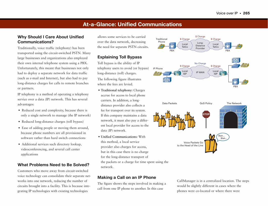
Voice over IP • 265
Why Should I Care About UnifiedCommunications?Traditionally, voice traffic (telephony) has been
transported using the circuit-switched PSTN. Many
large businesses and organizations also employed
their own internal telephone system using a PBX.
Unfortunately, this meant that businesses not only
had to deploy a separate network for data traffic
(such as e-mail and Internet), but also had to pay
long-distance charges for calls to remote branches
or partners.
IP telephony is a method of operating a telephony
service over a data (IP) network. This has several
advantages:
• Reduced cost and complexity, because there is
only a single network to manage (the IP network)
• Reduced long-distance charges (toll bypass)
• Ease of adding people or moving them around,
because phone numbers are all provisioned in
software rather than hard switch connections
• Additional services such directory lookup,
videoconferencing, and several call center
applications
What Problems Need to Be Solved?Customers who move away from circuit-switched
voice technology can consolidate their separate net-
works into one network, reducing the number of
circuits brought into a facility. This is because inte-
grating IP technologies with existing technologies
CallManager is in a centralized location. The steps
would be slightly different in cases where the
phones were co-located or where there were
allows some services to be carried
over the data network, decreasing
the need for separate PSTN circuits.
Explaining Toll BypassToll bypass is the ability of IP
telephony users to avoid (or bypass)
long-distance (toll) charges.
The following figure illustrates
where the fees are levied.
• Traditional telephony: Charges
accrue for access to local phone
carriers. In addition, a long-
distance provider also collects a
fee for transport over its system.
If this company maintains a data
network, it must also pay a differ-
ent local provider for access to the
data (IP) network.
• Unified Communications: With
this method, a local service
provider also charges for access,
but in this case there is no charge
for the long-distance transport of
the packets or a charge for time spent using the
network.
Making a Call on an IP PhoneThe figure shows the steps involved in making a
call from one IP phone to another. In this case
PBX PBX
PBX
TraditionalPhone
$ Charge
Long-DistanceProvider
LocalTelCo
LocalTelCo
$ Charge$ Charge
$ Charge
IP WANLocalISP
LocalISP
No Charge$ Charge
IP Phone
M
M
V V
At-a-Glance: Unified Communications
QoS PolicyData Packets The Network
Voice Packets Goto the Head of the Line
STOP
Blah... Blah...
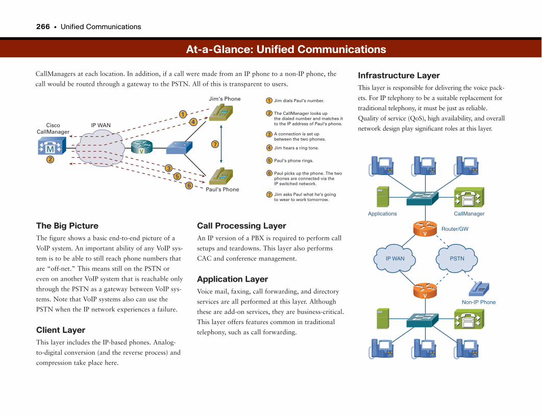
266 • Unified Communications
CallManagers at each location. In addition, if a call were made from an IP phone to a non-IP phone, the
call would be routed through a gateway to the PSTN. All of this is transparent to users.Infrastructure LayerThis layer is responsible for delivering the voice pack-
ets. For IP telephony to be a suitable replacement for
traditional telephony, it must be just as reliable.
Quality of service (QoS), high availability, and overall
network design play significant roles at this layer.
The Big PictureThe figure shows a basic end-to-end picture of a
VoIP system. An important ability of any VoIP sys-
tem is to be able to still reach phone numbers that
are “off-net.” This means still on the PSTN or
even on another VoIP system that is reachable only
through the PSTN as a gateway between VoIP sys-
tems. Note that VoIP systems also can use the
PSTN when the IP network experiences a failure.
Client LayerThis layer includes the IP-based phones. Analog-
to-digital conversion (and the reverse process) and
compression take place here.
At-a-Glance: Unified Communications
CiscoCallManager
Jim's Phone
Paul's Phone
Paul's phone rings.
Paul picks up the phone. The two phones are connected via the IP switched network.
Jim asks Paul what he's goingto wear to work tomorrow.
Jim hears a ring tone.
A connection is set upbetween the two phones.
The CallManager looks upthe dialed number and matches itto the IP address of Paul's phone.
Jim dials Paul's number.
IP WAN
1
1
3
36
6
2
2 5
5
74
4
7
M V
IP WAN PSTN
Router/GWV
V
CallManagerApplications
Non-IP Phone
Call Processing LayerAn IP version of a PBX is required to perform call
setups and teardowns. This layer also performs
CAC and conference management.
Application LayerVoice mail, faxing, call forwarding, and directory
services are all performed at this layer. Although
these are add-on services, they are business-critical.
This layer offers features common in traditional
telephony, such as call forwarding.
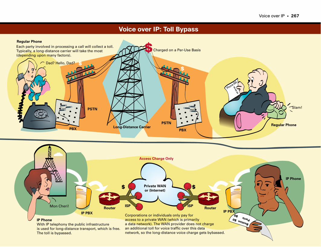
Voice over IP • 267
Regular Phone
Regular Phone
Dad? Hello, Dad?
PBX
PSTN
PBX
PSTNLong-Distance Carrier
Slam!
Phone Bill
$$
$
Each party involved in processing a call will collect a toll.Typically, a long-distance carrier will take the most (depending upon many factors).
$$
$ $
$
IP Phone
With IP telephony the public infrastructureis used for long-distance transport, which is free. The toll is bypassed.
Mon Cheri!
IP PBX IP PBXRouter Router
ISP ISP
Private WAN
or (Internet)
IP Phone
Access Charge Only
Boston $0 Paris $0
Charged on a Per-Use Basis
Corporations or individuals only pay foraccess to a private WAN (which is primarilya data network). The WAN provider does not chargean additional toll for voice traffic over this datanetwork, so the long-distance voice charge gets bybassed.
Voice over IP: Toll Bypass

Quality of Service

Converged Networks and QoSTraditionally, computer networks transported data applications and provided
file storage services. The modern business network is also the communications
backbone, supporting many applications, including delay-sensitive data, but
also voice, high-quality video, and web-based conferencing and collaboration.
Because the network is now a communications backbone, it must provide pre-
dictable, measurable, and sometimes guaranteed services.
But the network has finite resources in terms of bandwidth, how many packets
can be switched and routed through it, and how quickly packets can be passed
to their destinations. To provide a communications backbone, the network
must manage its resources to provide the service levels needed for many appli-
cations to coexist on the network.
Different applications have different requirements. Some applications may
have fairly tolerant requirements. For example, with web page browsing, it
typically does not matter if the response time is delayed a second or two.
Other real-time communications applications, such as VoIP and video over IP,
have much stricter tolerances, in which delay is measured in milliseconds, not
seconds. Without proper intelligence in the network, some applications could
get in the way of real-time applications, causing poor voice quality or other
undesirable levels of service.
As mentioned, in many cases an application such as a web browser is not
impacted by waiting a second or two. It’s the network’s job to figure out
which applications can wait and which need to be transported immediately.
What Is QoS?QoS is a collection of features designed to ensure reliable, timely delivery of
voice and other “real-time” packets across an IP network. Unlike data files,
which can be broken up, sent in random order, and reassembled at the receiv-
ing end, it is critical for voice packets to arrive in order with minimal delay.
QoS does just that. Think of it as VIP treatment for packets.
QoS allows different types of applications to contend for network resources.
Voice, video, and critical data applications may be granted priority or preferential
services from network devices so that they do not degrade to the point of
being unusable.
The QoS toolset includes mechanisms for managing network bandwidth,
marking and prioritizing packets, and intelligent queuing algorithms that
engage when the network is congested. Each type of application can be
assigned a relative priority on the network. For example, VoIP may be
assigned relatively high, and web browsing may be assigned relatively low.
When network resources are not in contention—that is, plenty are available—
QoS generally lets the network switch packets in a first-in-first-out (FIFO)
queuing strategy. When there is contention for network resources—that is,
when the network experiences congestion—QoS engages to provide a more
intelligent queuing strategy to protect the service level of the highest-priority
applications, while asking applications with lower priority to wait.
QoS is not only useful in protecting high-priority traffic. It also protects the
network from undesirable traffic such as the exponential propagation of
worms (as discussed in Part IV, “Network Availability”). It’s worth noting that
QoS can’t fix everything. For example, QoS is not designed to compensate or
make up for an underprovisioned network or a real-time application’s inability
to communicate efficiently.
QoS and Unified CommunicationsThe majority of applications in the Unified Communications suite are high-
priority real-time applications, with relatively strict demands on the network.
VoIP and video over IP, for example, need to stay within strict tolerances to
have sufficient voice quality and video display quality to be usable. Other
types of applications in the Unified Communications suite may be more toler-
ant. For example, with application sharing and instant messaging, it is not
noticeable if response time increases to a second or two.
So, what factors matter for Unified Communications?
• Loss is the difference between the number of packets sent and received. Loss
typically is a function of availability. If the network is designed to be highly
available, loss during periods of noncongestion should be near zero. During
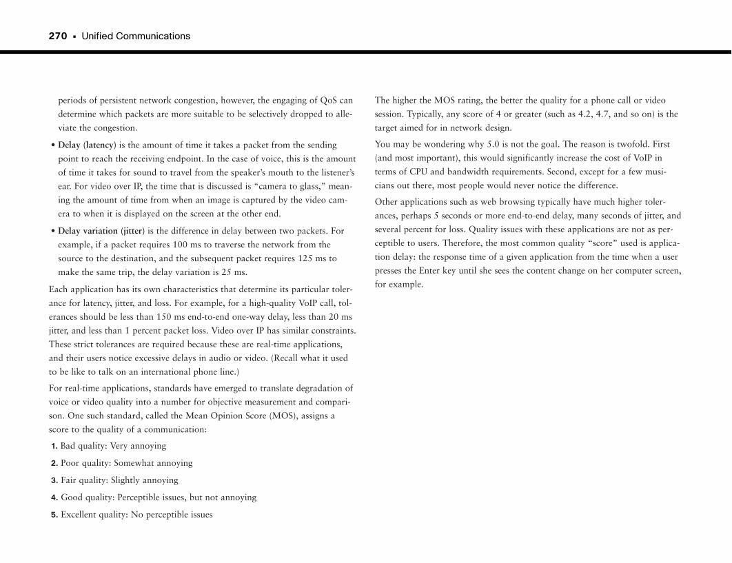
270 • Unified Communications
periods of persistent network congestion, however, the engaging of QoS can
determine which packets are more suitable to be selectively dropped to alle-
viate the congestion.
• Delay (latency) is the amount of time it takes a packet from the sending
point to reach the receiving endpoint. In the case of voice, this is the amount
of time it takes for sound to travel from the speaker’s mouth to the listener’s
ear. For video over IP, the time that is discussed is “camera to glass,” mean-
ing the amount of time from when an image is captured by the video cam-
era to when it is displayed on the screen at the other end.
• Delay variation (jitter) is the difference in delay between two packets. For
example, if a packet requires 100 ms to traverse the network from the
source to the destination, and the subsequent packet requires 125 ms to
make the same trip, the delay variation is 25 ms.
Each application has its own characteristics that determine its particular toler-
ance for latency, jitter, and loss. For example, for a high-quality VoIP call, tol-
erances should be less than 150 ms end-to-end one-way delay, less than 20 ms
jitter, and less than 1 percent packet loss. Video over IP has similar constraints.
These strict tolerances are required because these are real-time applications,
and their users notice excessive delays in audio or video. (Recall what it used
to be like to talk on an international phone line.)
For real-time applications, standards have emerged to translate degradation of
voice or video quality into a number for objective measurement and compari-
son. One such standard, called the Mean Opinion Score (MOS), assigns a
score to the quality of a communication:
1. Bad quality: Very annoying
2. Poor quality: Somewhat annoying
3. Fair quality: Slightly annoying
4. Good quality: Perceptible issues, but not annoying
5. Excellent quality: No perceptible issues
The higher the MOS rating, the better the quality for a phone call or video
session. Typically, any score of 4 or greater (such as 4.2, 4.7, and so on) is the
target aimed for in network design.
You may be wondering why 5.0 is not the goal. The reason is twofold. First
(and most important), this would significantly increase the cost of VoIP in
terms of CPU and bandwidth requirements. Second, except for a few musi-
cians out there, most people would never notice the difference.
Other applications such as web browsing typically have much higher toler-
ances, perhaps 5 seconds or more end-to-end delay, many seconds of jitter, and
several percent for loss. Quality issues with these applications are not as per-
ceptible to users. Therefore, the most common quality “score” used is applica-
tion delay: the response time of a given application from the time when a user
presses the Enter key until she sees the content change on her computer screen,
for example.
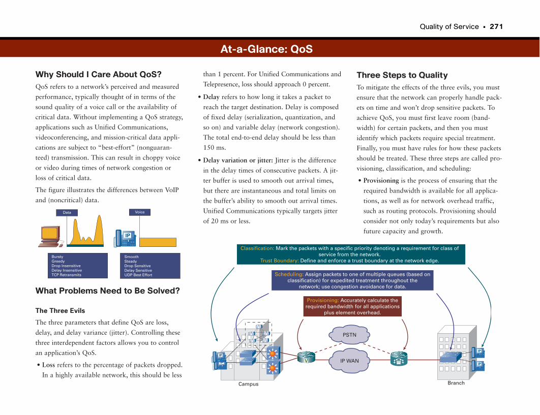
Quality of Service • 271
Why Should I Care About QoS?QoS refers to a network’s perceived and measured
performance, typically thought of in terms of the
sound quality of a voice call or the availability of
critical data. Without implementing a QoS strategy,
applications such as Unified Communications,
videoconferencing, and mission-critical data appli-
cations are subject to “best-effort” (nonguaran-
teed) transmission. This can result in choppy voice
or video during times of network congestion or
loss of critical data.
The figure illustrates the differences between VoIP
and (noncritical) data.
What Problems Need to Be Solved?
The Three Evils
The three parameters that define QoS are loss,
delay, and delay variance (jitter). Controlling these
three interdependent factors allows you to control
an application’s QoS.
• Loss refers to the percentage of packets dropped.
In a highly available network, this should be less
Three Steps to QualityTo mitigate the effects of the three evils, you must
ensure that the network can properly handle pack-
ets on time and won’t drop sensitive packets. To
achieve QoS, you must first leave room (band-
width) for certain packets, and then you must
identify which packets require special treatment.
Finally, you must have rules for how these packets
should be treated. These three steps are called pro-
visioning, classification, and scheduling:
• Provisioning is the process of ensuring that the
required bandwidth is available for all applica-
tions, as well as for network overhead traffic,
such as routing protocols. Provisioning should
consider not only today’s requirements but also
future capacity and growth.
than 1 percent. For Unified Communications and
Telepresence, loss should approach 0 percent.
• Delay refers to how long it takes a packet to
reach the target destination. Delay is composed
of fixed delay (serialization, quantization, and
so on) and variable delay (network congestion).
The total end-to-end delay should be less than
150 ms.
• Delay variation or jitter: Jitter is the difference
in the delay times of consecutive packets. A jit-
ter buffer is used to smooth out arrival times,
but there are instantaneous and total limits on
the buffer’s ability to smooth out arrival times.
Unified Communications typically targets jitter
of 20 ms or less.Data
SmoothSteadyDrop SensitiveDelay SensitiveUDP Best Effort
Voice
BurstyGreedyDrop InsensitiveDelay InsensitiveTCP Retransmits
IP
At-a-Glance: QoS
Provisioning: Accurately calculate therequired bandwidth for all applications
plus element overhead.
Scheduling: Assign packets to one of multiple queues (based onclassification) for expedited treatment throughout the
network; use congestion avoidance for data.
Classification: Mark the packets with a specific priority denoting a requirement for class ofservice from the network.
Trust Boundary: Define and enforce a trust boundary at the network edge.
PSTN
IP WAN
MMMMM
Campus Branch
IP
IP
IP
IP
V
272 • Unified Communications
• Classification refers to marking packets with a spe-
cific priority denoting a requirement for special
service from the network. This can be done at dif-
ferent places in the network by Layer 2 or Layer 3
devices, or by endpoints themselves. Typical classi-
fication schemes identify priorities of Critical (voice
and mission-critical data), High (video), Normal
(e-mail, Internet access), and Low (fax, FTP).
• Scheduling is the process of assigning packets to
one of multiple queues (based on classification)
for priority treatment through the network. A
good example of this is commercial airline board-
ing schemes. First-class passengers board first. All
frequent flyers may then board. Group 1 may
board next, followed by Group 2, and so on.
Low-Bandwidth ToolsIn addition to the three main steps to ensure QoS,
some link-specific tools are also needed, such as
traffic shaping and Link Fragmentation and
In addition to network congestion, one of the
primary contributors to both delay and jitter is
serialization delay. This is often caused by a time-
sensitive packet getting “stuck in traffic” behind a
large data packet (such as FTP). Link fragmenta-
tion is the process of breaking up large packets to
allow smaller, more time-sensitive packets to
proceed through the network in a timely manner.
Interleaving is the processes of “weaving” the
time-sensitive packets into the train of fragmented
data packets.
Traffic shaping is a technique to deal with instan-
taneous or sustained bursts of traffic above a
desired rate. For example, if a connection can han-
dle 10 Mbps, but a burst occurs that is 12 Mbps,
followed by a period of 8 Mbps, traffic shaping
smoothes out the traffic to stay within the 10-
Mbps overall line limit. Traffic shaping works by
delaying part of the traffic burst until the traffic
rate falls below the line rate, and the delayed traf-
fic can then be transmitted. As a result, instead of
the traffic being peaks and valleys, it is
“smoother” and more linear and is shaped flat-
ter—hence the term traffic shaping.
Interleaving (LFI), especially when routing traffic
over low-bandwidth (768-kbps or slower) links.
Traffic shaping is a method of throttling back
packet transmission rates. If line-speed mismatches
exist between remote offices, the service provider
connecting the offices may be forced to drop arbi-
trary packets going to the slower link.
To keep high-priority packets from being dropped,
an enterprise can engineer its traffic by provision-
ing its traffic on the slower link. Traffic engineer-
ing also allows the enterprise to decide which
packets can be, or should be, dropped (low-priority
packets) when instantaneous congestion occurs.
The three most common cases of traffic engineer-
ing occur when there are
• Line-speed mismatches
• Oversubscription, planned or unplanned
• Traffic bursts
At-a-Glance: QoS
75%
The above percentages are just starting guidelines; each networkand application might require different allocations of bandwidth.
HQ
Frame Relayor ATM
64Kbps
T1 T1 T1
T1
Remote Sites
Committed Rate= 64 Kbps
Voice
Video
Data
1 1
33
221 13 22
Before LFI
Voice
Serialization Delay
After LFI
Data Data Voice Data Voice
Voice Data
Quality of Service • 273
Ice Cream = Voice Frozen Waffles = Voice Conference
Meat =Fruits =Vegetables =
Non-perishables = Routing Overhead
HotDogs
HotDogs
Bulk of EnterpriseData
Second Class:All Others As YouArrive
IceCream
IceCream
IceCream
IceCream
IceCream
IceCream
IceCream
IceCream
IceCream
IceCream
IceCream
IceCream
IceCream
Bananas
FrozenWaffles
FrozenWaffles
FrozenWaffles
Hamburger
RiceCakes
RiceCakes
RiceCakes
RiceCakes
400 lbs.
If a 400-pound rice cake (really big e-mail attach-ment) shows up, it cantake so long to process off the ferry that all the ice cream melts anyway.
How Link Fragmentationand Interleaving (LFI) Works
First ClassPriority:Ice Cream
All Others (Second, Third,Fourth Classes)Must Wait
The Ferry: Que
The Ferry: Que
We want hot dogs!We want peas!We want kiwis andcookbooks, please!
Some queuing systems always give preferential treatment to high-priority traffic. This ensures that the ice cream (time-sensitive packets) always arrives on time, but it comes at the cost of choking out the meats and vege-tables (regular data) that make up the bulk of theenterprise data diet (and is critical to its survival).
Packet Flow
Low latency queuing sets aside some percentage (30% for example) for high- priority traffic (ice cream) but also allows space for regular data, and lower priority data and instructions (rice cakes and cookbooks). Within each data space, an enterprise can define what ratios work best for them (more meats than fruits andveggies, or vice versa). The result is a healthy diet, and no (or very little) meltedice cream.
First Class:30% Reservedfor Ice Cream.But All SeatsMust Fill.
Hmm.What to do?
FruitO’s Okra Peas
Peas
GrapesCookbooks
Cookbooks
RolledOats
Whew!
Yea!
RiceCakes
MacaroniGranola
KiwisBuffaloWings
}
The problem is solved by breakng up rice cakesinto smaller pieces and staggering them with the stuff that needs to get off the ferry fast. Once unloaded,it can be reassembled.
How Packets Are Prioritized

Unified Personal Communications
Too Many Communications, Too Little TimeThe telephone was the primary form of communication for many years. But
today we have many choices for how we communicate. We can telephone (and
there are about a dozen ways we can do that), we can call people on their
mobile phones, leave a voice mail, send e-mail, join an audioconference, call
on a video phone, join a web conference and share applications, instant mes-
sage, and so on.
If we needed a different device for every type of communication, we would
also need about a dozen arms to carry them. Fortunately, we have the concept
of unifying personal communications.
Unify MeUnifying communications means different things to different people, but most
people agree on a couple of key elements. Different communications systems
are converging, making it hard to tell where one stops and the other begins.
For example, with VoIP-based systems, you usually can listen to your voice
mail from a computer by clicking the message’s audio file. Often meeting con-
ference bridges have a facility to share applications between the participants’
computers.
The second element of unifying communications is device convergence. Mobile
phones are also still cameras, video cameras, MP3 players, and handheld com-
puters in the case of a PDA. Laptop computers can act as a VoIP telephone
endpoint (called a “softphone,” a merger of the terms “software” and
“phone”). Laptop computers equipped with small video cameras can also act
as a video phone. The laptop and handheld computer, or PDA in particular,
are both heading toward being a unified communications device, supporting a
whole suite of possible communications.
Unified Communications is also the Cisco term for unification of business
communications, including voice, video, instant messaging, e-mail, application
sharing, conferencing, and call centers.
Cisco Unified Personal Communicator (CUPC)The Cisco Unified Personal Communicator (CUPC) refers to an integrated
Unified Communications client that runs on a laptop or handheld computer,
bringing together many forms of communications on a single device. Types of
communications include voice, video, instant messaging, voice mail, e-mail,
application sharing, and web conferencing and collaboration.
The CUPC endpoint is integrated into the business Unified Communications
system. Therefore, it has a phone number in the corporate dial plan and is
integrated into all other communications systems in the business, making it a
very productive tool for employees.

276 • Unified Communications
Why Should I Care About UnifyingCommunications?To operate and grow a successful business, employ-
ees must be able to communicate with other
employees, suppliers, customers, and other busi-
nesses through a diverse set of communications
media, including
• Voice
• Mobile voice
• Voice mail
• Audioconferencing
• Instant messaging
• Videoconferencing
• Web conferencing
Communications must be accessible wherever
employees are: at a corporate headquarters desk, at
branch offices, on the road, and from home. When
not integrated, diverse communications methods
can lead to inefficiencies and difficulties in trying
to bridge different types of communications.
Missed or inefficient communications lead to loss
of productivity, more costly business transactions,
and missed opportunities.
What Problems Need to Be Solved?Providing a single application that integrates multi-
ple communications paths and media types requires
coordination among many teams and technologies.
How Unifying Communications WorksThe Cisco Unified Communications solution pro-
vides a suite of communications services that,
when integrated, provide seamless connections
between types of communications. The system
gives employees the ability to access these tools
from a desk, laptop, home, or while traveling.
Visual interfaces let employees easily manage their
communications, no matter which form they are in,
such as e-mail, voice mail, IM, or web conference.
Reach out and Touch SomeoneTime and productivity are lost when people try to
reach each other and try to figure out which com-
munication method they can use. Unified
The solution must bridge different communica-
tions systems and media and provide real-time
access to people on the right systems when they
are needed.
At-a-Glance: Unified Communications
CommunicationComplexity
Global
Mobile
Virtual
Cisco UnityVisual Voice Mail
Cisco UnifiedPersonal
Communicator Cisco UnifiedPresence
Cisco UnifiedMeetingPlaceWebconferencing
Cisco UnifiedCommunications Manager
IP Communications System
Video

Unified Personal Communications • 277
Communications allows people to see how to best
reach the people they need to communicate with,
whether through instant messaging, phone, or
videoconferencing. Unified Communications great-
ly speeds up the communication process, which
often means closing a deal faster or responding to
a customer issue faster.
Increased ProductivityProductivity can also be enhanced through the use
of a single “in box” for communications. This
allows users to easily see a history of their commu-
nications or listen to voice mail through the same
visual interface. They can respond with one of sev-
eral communication types, such as e-mail, voice
mail, or click to call back.
With this tool, employees can sort and manage
communications as they would with e-mail, no
matter where they are or what device they
currently have access to.
This system improves the chances of reaching peo-
ple, reducing missed communications and having
to retry with other forms of communication. For
example, you can find out via Presence and Instant
Messaging whether someone is available, see what
her preferred or current communications medium
is, and click to call.
At-a-Glance: Unified Communications
Management CapabilitiesEmployees can improve their productivity by taking
advantage of powerful call management capabili-
ties. Users can make a call from a desk phone
using a visual directory or use a softphone on a
laptop to click-to-dial from an instant-messaging
contacts list. Users can easily add capabilities to
the communication, such as adding a voice call to
an instant messaging session or converting to a
multiperson web conference to share documents.
Visual screen “pops” can alert people to incoming
calls and, by integrating with the corporate direc-
tory, display their standard directory information.

Meeting Collaboration Spaces
Meetings, Meetings, MeetingsDid you ever participate in Take Your Child to Work Day, only to have your
kids sum up your years of education, long hours, hard work, and hard-learned
experience like this: “It’s boring. They sit in meeting rooms with people all
day.”? Anyone who has ever worked for a company knows that the one place
we all seem to spend the majority of our time is in meetings.
Traditionally, the business meeting was a place you went. You packed up your
notebook (the paper kind, not the computer) and pen and headed to a drably
decorated conference room to get the day’s status report, or to argue with the
other participants, who were just as excited as you to be there.
If you were “lucky,” the meeting also had visuals, and you got the pleasure of
listening to a presenter drone on and on and on (we call this “death by
PowerPoint”).
Without wireless network access, laptops were not that useful. Typically par-
ticipants stood in line for only a single wired network port, far in advance of
the meeting (much like an opening of Star Wars). The standard meeting com-
munications systems were old-fashioned face-to-face, and an audio bridge for
those lucky enough—err, unlucky enough—not to be physically in the meeting
room.
Meetings Are an Activity, Not a PlaceBusiness meetings are (thankfully) quickly evolving into a collaborative activity
that can occur regardless of the participants’ location. Meetings happen any-
where, at any time, planned or unplanned. An unplanned meeting may start
with two people instant messaging about an idea. Audio and a few more
participants can be added on-the-fly. The meeting can even grow into a full-
fledged web conference, with computer screens being shared with others
electronically so that everyone can see what is being discussed.
To be most productive, meetings have many different forms of possible commu-
nications, and participants can move from one type to another in an integrated
way. For example, to attend a meeting, participants may click the calendar
item in their calendaring system to launch a meeting client. They can do so in
a meeting room, or more often at their desks, or wherever they happen to be
at the meeting time. The client automatically places a call to the participants’
chosen number and device for joining the audio (and possibly video) conference.
Participants can see who is attending and who is speaking, because Presence
(discussed in the next topic) is integrated. As the meeting progresses, partici-
pants can discuss ideas with audio, share slides that are displayed on every-
one’s laptop screen, send e-mail, and even discuss an idea offline with someone
using instant messaging. Participants can also see and review meeting minutes
as they are being typed. (This is helpful for colleagues who never manage to
show up on time.)
What makes all this possible is the tight integration of various communica-
tions under a Unified Communications system.
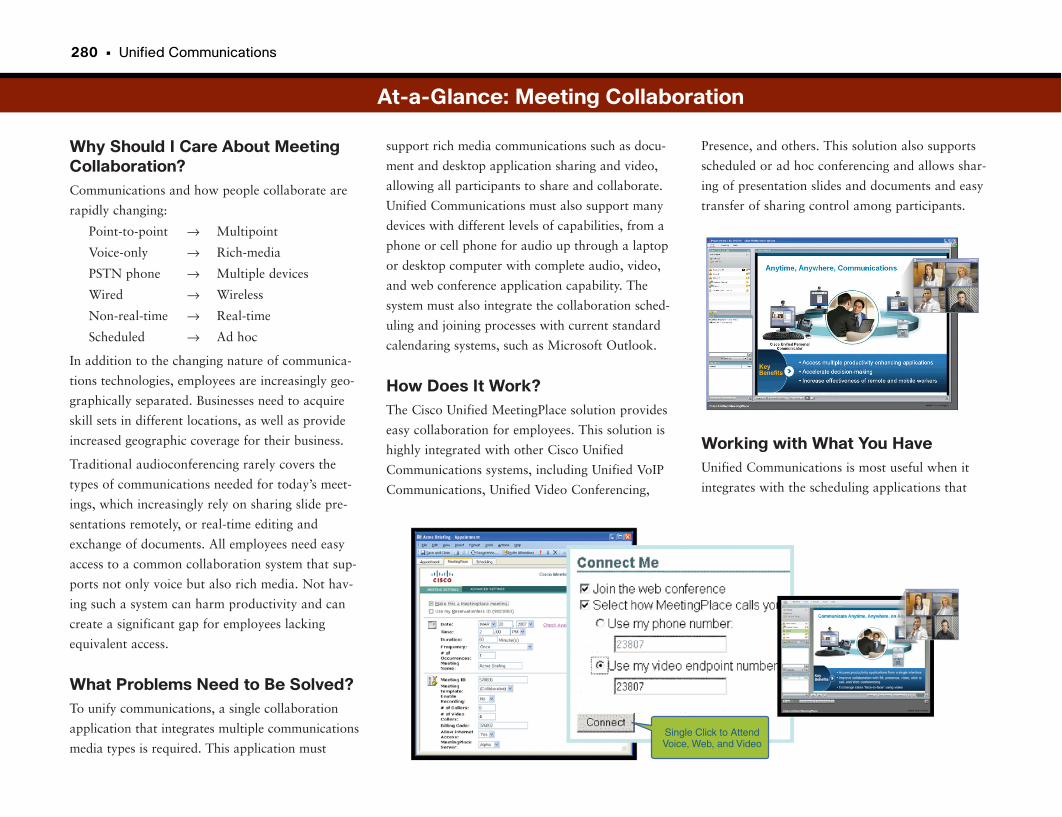
280 • Unified Communications
Why Should I Care About MeetingCollaboration?Communications and how people collaborate are
rapidly changing:
Point-to-point → Multipoint
Voice-only → Rich-media
PSTN phone → Multiple devices
Wired → Wireless
Non-real-time → Real-time
Scheduled → Ad hoc
In addition to the changing nature of communica-
tions technologies, employees are increasingly geo-
graphically separated. Businesses need to acquire
skill sets in different locations, as well as provide
increased geographic coverage for their business.
Traditional audioconferencing rarely covers the
types of communications needed for today’s meet-
ings, which increasingly rely on sharing slide pre-
sentations remotely, or real-time editing and
exchange of documents. All employees need easy
access to a common collaboration system that sup-
ports not only voice but also rich media. Not hav-
ing such a system can harm productivity and can
create a significant gap for employees lacking
equivalent access.
What Problems Need to Be Solved?To unify communications, a single collaboration
application that integrates multiple communications
media types is required. This application must
Presence, and others. This solution also supports
scheduled or ad hoc conferencing and allows shar-
ing of presentation slides and documents and easy
transfer of sharing control among participants.
Working with What You HaveUnified Communications is most useful when it
integrates with the scheduling applications that
support rich media communications such as docu-
ment and desktop application sharing and video,
allowing all participants to share and collaborate.
Unified Communications must also support many
devices with different levels of capabilities, from a
phone or cell phone for audio up through a laptop
or desktop computer with complete audio, video,
and web conference application capability. The
system must also integrate the collaboration sched-
uling and joining processes with current standard
calendaring systems, such as Microsoft Outlook.
How Does It Work?The Cisco Unified MeetingPlace solution provides
easy collaboration for employees. This solution is
highly integrated with other Cisco Unified
Communications systems, including Unified VoIP
Communications, Unified Video Conferencing,
At-a-Glance: Meeting Collaboration
All video and audio signals arecobined and transmitted using a single Video-over-IP traffic stream.
This requires only a single Ethernetport to connect to the corporate network
•
•
Single Click to AttendVoice, Web, and Video
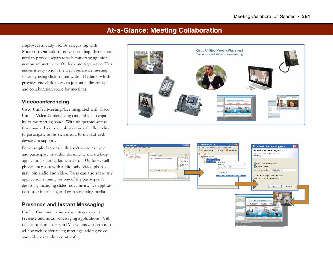
Meeting Collaboration Spaces • 281
employees already use. By integrating with
Microsoft Outlook for easy scheduling, there is no
need to provide separate web conferencing infor-
mation adjunct to the Outlook meeting notice. This
makes it easy to join the web conference meeting
space by using click-to-join within Outlook, which
provides one-click access to join an audio bridge
and collaboration space for meetings.
VideoconferencingCisco Unified MeetingPlace integrated with Cisco
Unified Video Conferencing can add video capabil-
ity to the meeting space. With ubiquitous access
from many devices, employees have the flexibility
to participate in the rich media forms that each
device can support.
For example, laptops with a softphone can join
and participate in audio, document, and desktop
application sharing, launched from Outlook. Cell
phones may join with audio only. Video phones
may join audio and video. Users can also share any
application running on one of the participant’s
desktops, including slides, documents, live applica-
tions user interfaces, and even streaming media.
Presence and Instant MessagingUnified Communications also integrate with
Presence and instant-messaging applications. With
this feature, multiperson IM sessions can turn into
ad hoc web conferencing meetings, adding voice
and video capabilities on-the-fly.
At-a-Glance: Meeting Collaboration
Cisco Unified MeetingPlace andCisco Unified Videoconferencing

Traditional Videoconferencing
I See YouVideoconferencing is similar to an audioconference call in that multiple people
connect to a central site to communicate with each other. Videoconference net-
works are converging onto IP networks, allowing greater flexibility and lower cost.
Traditional videoconferencing systems used a protocol called H.320, which
allowed the transmission of video across public telephone lines using ISDN.
Typically, companies built expensive videoconference rooms that were shared,
requiring reservations. During the videoconference, people wanted to share
presentations and images and view notes or whiteboard scribbles. The cost of
videoconferences was high in both the investment in equipment and the
monthly cost of ISDN, especially because these systems were not IP-based and
used non-IP telecom protocols (which means they were completely separate
from the corporate network).
Although the cost of creating these videoconference nodes is high, the expense
is still less than flying a group of people to a common location, putting them
up in hotels, and so on, especially for international meetings. Typical uses of
videoconferences include the following:
• Executive broadcasts and communications
• High-impact meetings
• Training
With the convergence of video and voice-over-IP networks, videoconferencing
was a natural technology to transfer to converged IP networks.
Video over IP NetworksThe introduction of videoconferencing over IP networks had to resolve two
issues:
• Providing videoconferencing equipment that could operate on traditional
data networks (using TCP/IP over Ethernet networks, for instance)
• Connecting existing H.320 videoconference locations to the IP-based systems
The International Telecommunications Union (ITU) H.323 protocol is the
standard for real-time multimedia communications and conferencing over IP
networks. For videoconferencing, H.323 breaks the dependence on expensive
conferencing equipment, costly monthly network fees, and dedicated facilities.
H.323 lets you connect videoconferencing equipment anywhere a traditional
IP network connection exists. Individuals and teams can plug inexpensive
video cameras into the corporate network, or across the Internet, and conduct
videoconferencing essentially anywhere without dedicated facilities.
Although H.323 addresses the real-time transmission of video and audio, users
still want to write and view whiteboard notes, exchange files, or share an
application. The ITU T.120 protocol addresses these tasks. The standard iden-
tifies how to reliably and efficiently distribute files and graphical information
in real time during a videoconference.
As with any real-time or multimedia application, the IP network design must
accommodate the requirements of these protocols. For videoconferencing, the net-
work must ensure that the video and data transmissions reach their destinations
in a timely manner, with minimal loss and delay. To accomplish this task, the net-
works use quality of service (QoS) prioritization and queuing mechanisms.
Traditional application traffic is tolerant of network delays or drops because
networks can always retransmit the data. Videoconferencing traffic has a dif-
ferent traffic profile from that of data but is similar to voice traffic. There is
no need to retransmit video frames if some are lost, because the video and
audio continue to move forward. However, network delay or loss can cause
the videoconference to look choppy or, worse, appear to lock up. Participants
in a videoconference can find the delay frustrating and even unproductive.
Aside from QoS, the network must also handle the sheer capacity of videocon-
ferencing traffic. Video and multimedia generate a large amount of network
traffic. Therefore, videoconferencing might not be possible on slow WAN links
or congested network connections.
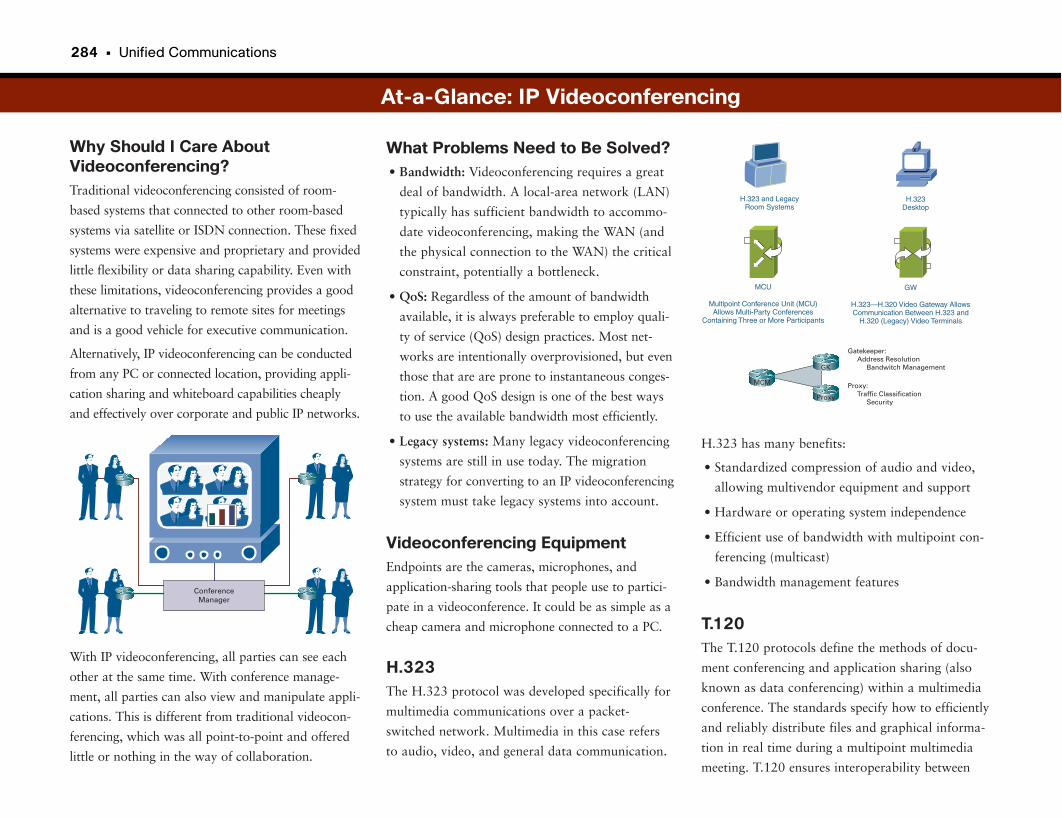
284 • Unified Communications
Why Should I Care AboutVideoconferencing?Traditional videoconferencing consisted of room-
based systems that connected to other room-based
systems via satellite or ISDN connection. These fixed
systems were expensive and proprietary and provided
little flexibility or data sharing capability. Even with
these limitations, videoconferencing provides a good
alternative to traveling to remote sites for meetings
and is a good vehicle for executive communication.
Alternatively, IP videoconferencing can be conducted
from any PC or connected location, providing appli-
cation sharing and whiteboard capabilities cheaply
and effectively over corporate and public IP networks.
With IP videoconferencing, all parties can see each
other at the same time. With conference manage-
ment, all parties can also view and manipulate appli-
cations. This is different from traditional videocon-
ferencing, which was all point-to-point and offered
little or nothing in the way of collaboration.
H.323 has many benefits:
• Standardized compression of audio and video,
allowing multivendor equipment and support
• Hardware or operating system independence
• Efficient use of bandwidth with multipoint con-
ferencing (multicast)
• Bandwidth management features
T.120The T.120 protocols define the methods of docu-
ment conferencing and application sharing (also
known as data conferencing) within a multimedia
conference. The standards specify how to efficiently
and reliably distribute files and graphical informa-
tion in real time during a multipoint multimedia
meeting. T.120 ensures interoperability between
What Problems Need to Be Solved?• Bandwidth: Videoconferencing requires a great
deal of bandwidth. A local-area network (LAN)
typically has sufficient bandwidth to accommo-
date videoconferencing, making the WAN (and
the physical connection to the WAN) the critical
constraint, potentially a bottleneck.
• QoS: Regardless of the amount of bandwidth
available, it is always preferable to employ quali-
ty of service (QoS) design practices. Most net-
works are intentionally overprovisioned, but even
those that are are prone to instantaneous conges-
tion. A good QoS design is one of the best ways
to use the available bandwidth most efficiently.
• Legacy systems: Many legacy videoconferencing
systems are still in use today. The migration
strategy for converting to an IP videoconferencing
system must take legacy systems into account.
Videoconferencing EquipmentEndpoints are the cameras, microphones, and
application-sharing tools that people use to partici-
pate in a videoconference. It could be as simple as a
cheap camera and microphone connected to a PC.
H.323The H.323 protocol was developed specifically for
multimedia communications over a packet-
switched network. Multimedia in this case refers
to audio, video, and general data communication.
At-a-Glance: IP Videoconferencing
ConferenceManager
H.323 and LegacyRoom Systems
H.323Desktop
MCU
Multipoint Conference Unit (MCU)Allows Multi-Party Conferences
Containing Three or More Participants
GW
H.323—H.320 Video Gateway AllowsCommunication Between H.323 and
H.320 (Legacy) Video Terminals
MCMMCM
GK
Proxy
Gatekeeper: Address Resolution Bandwitch Management
Proxy: Traffic Classification
Security
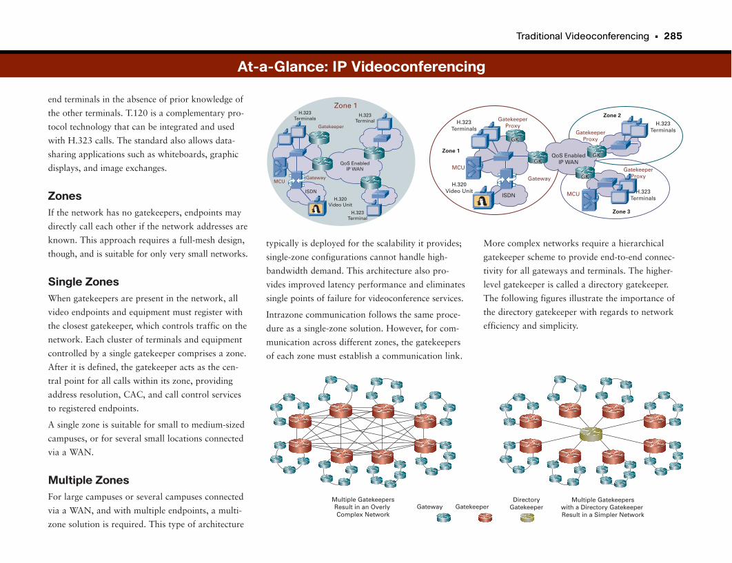
Traditional Videoconferencing • 285
end terminals in the absence of prior knowledge of
the other terminals. T.120 is a complementary pro-
tocol technology that can be integrated and used
with H.323 calls. The standard also allows data-
sharing applications such as whiteboards, graphic
displays, and image exchanges.
ZonesIf the network has no gatekeepers, endpoints may
directly call each other if the network addresses are
known. This approach requires a full-mesh design,
though, and is suitable for only very small networks.
Single ZonesWhen gatekeepers are present in the network, all
video endpoints and equipment must register with
the closest gatekeeper, which controls traffic on the
network. Each cluster of terminals and equipment
controlled by a single gatekeeper comprises a zone.
After it is defined, the gatekeeper acts as the cen-
tral point for all calls within its zone, providing
address resolution, CAC, and call control services
to registered endpoints.
A single zone is suitable for small to medium-sized
campuses, or for several small locations connected
via a WAN.
Multiple ZonesFor large campuses or several campuses connected
via a WAN, and with multiple endpoints, a multi-
zone solution is required. This type of architecture
More complex networks require a hierarchical
gatekeeper scheme to provide end-to-end connec-
tivity for all gateways and terminals. The higher-
level gatekeeper is called a directory gatekeeper.
The following figures illustrate the importance of
the directory gatekeeper with regards to network
efficiency and simplicity.
typically is deployed for the scalability it provides;
single-zone configurations cannot handle high-
bandwidth demand. This architecture also pro-
vides improved latency performance and eliminates
single points of failure for videoconference services.
Intrazone communication follows the same proce-
dure as a single-zone solution. However, for com-
munication across different zones, the gatekeepers
of each zone must establish a communication link.
At-a-Glance: IP Videoconferencing
H.323Terminals
Zone 1
ISDN
MCUGateway
H.320Video Unit
QoS EnabledIP WAN
Gatekeeper
H.323Terminal
H.323Terminal H.323
Terminals
ISDN
GatekeeperProxy
H.320Video Unit
QoS EnabledIP WAN
Gateway
MCU
MCU
GatekeeperProxy
Zone 1
Zone 2
Zone 3
H.323Terminals
H.323Terminals
GatekeeperProxy
GK
GKGK
GK
Gateway GatekeeperDirectory
GatekeeperMultiple GatekeepersResult in an Overly Complex Network
Multiple Gatekeeperswith a Directory Gatekeeper Result in a Simpler Network
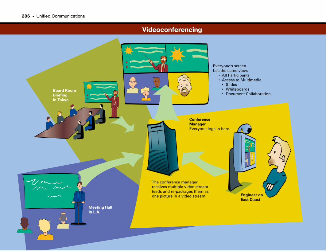
Conference
Manager
Everyone logs in here.
Engineer on
East Coast
Meeting Hall
in L.A.
Board Room
Briefing
in Tokyo
The conference managerreceives multiple video streamfeeds and re-packages them as one picture in a video stream.
Everyone’s screenhas the same view: • All Participants • Access to Multimedia • Slides • Whiteboards • Document Collaboration
Videoconferencing
286 • Unified Communications
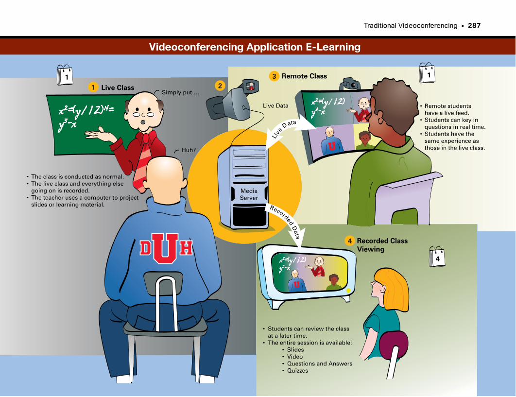
Traditional Videoconferencing • 287
Live Class
Live Data • Remote students have a live feed.• Students can key in questions in real time.• Students have the same experience as those in the live class.
MediaServer
Remote Class
Recorded Class
Viewing
• Students can review the class at a later time.• The entire session is available: • Slides • Video • Questions and Answers • Quizzes
• The class is conducted as normal.• The live class and everything else going on is recorded.• The teacher uses a computer to project slides or learning material.
Live
Data
RecordedD
ata
Simply put …
Huh?
1 2
3
4
1 1
4
Videoconferencing Application E-Learning

Telepresence
Conferencing Gets SimpleAudioconferencing revolutionized standard meeting practice, but when it was
first established, it required a conference operator to admit participants and
manage the conference. Conferencing evolved to being easy enough that
employees could quickly and easily organize their own conference bridges.
(However, we have been in plenty of meetings where the “ease” of today’s
conference bridge technology continues to elude some of the brightest engi-
neers.)
VoIP makes conferencing more flexible and cost-effective. Because the VoIP
packets are already digital encodings of audio, they can “simply” be routed to
a conferencing server, a really fast computer, that can take the digital audio
streams, combine them, and replay them back out to all the participants. Mix
in a dash of being able to point and click on a laptop to schedule and host a
conference, and voilà—conferencing can be used by everyone.
Video Killed the Radio StarVideoconferencing has been around for a while, starting with (as previously
discussed) specialized videoconferencing rooms that were connected by high-
speed connections through the PSTN. Seeing people added another dimension
to meetings.
Video over IP again made conferencing more flexible and cost-effective. The
data network hosting videoconferences, although bandwidth-consuming, was
yet another proof point for converging applications and media onto the network.
But something was still missing. Videoconferencing did not really take off to
the extent that audioconferencing did.
The Next-Best Thing to Being ThereWhat if someone told you that you could attend meetings in person halfway
around the world without ever boarding a plane? You would probably think
you were in a sci-fi movie. But it is not that far-fetched. It is possible. Well,
almost.
Telepresence is a new category of communications and collaboration designed
to make meeting participants feel like they are in the same room, even though
they may be thousands of miles apart. Based on high-definition video,
Telepresence pushes the envelope of what can be done with networks and
stretches the imagination of what is possible.
Simply put, Telepresence is based on two or more mirror-image rooms con-
nected by high-definition video displayed life-size on plasma HDTV screens.
The rooms and screens are positioned in such a way that the participants in
the room feel like their remote participants are in the room with them. The
meeting experience is so realistic that people turn to make eye contact, often
forgetting whether the person they are talking to is physically in the room or
distant. The system typically is designed to accommodate 10 to 12 people per
room (as opposed to a large conference hall).
All that’s missing is a way to shake hands. Cisco has not figured out that part
yet, but they are working on it.
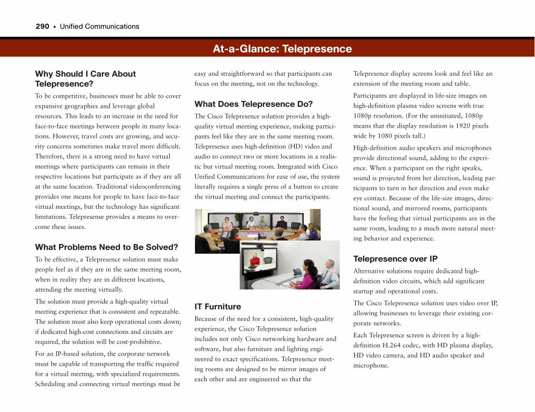
290 • Unified Communications
Why Should I Care AboutTelepresence?To be competitive, businesses must be able to cover
expansive geographies and leverage global
resources. This leads to an increase in the need for
face-to-face meetings between people in many loca-
tions. However, travel costs are growing, and secu-
rity concerns sometimes make travel more difficult.
Therefore, there is a strong need to have virtual
meetings where participants can remain in their
respective locations but participate as if they are all
at the same location. Traditional videoconferencing
provides one means for people to have face-to-face
virtual meetings, but the technology has significant
limitations. Telepresense provides a means to over-
come these issues.
What Problems Need to Be Solved?To be effective, a Telepresence solution must make
people feel as if they are in the same meeting room,
when in reality they are in different locations,
attending the meeting virtually.
The solution must provide a high-quality virtual
meeting experience that is consistent and repeatable.
The solution must also keep operational costs down;
if dedicated high-cost connections and circuits are
required, the solution will be cost-prohibitive.
For an IP-based solution, the corporate network
must be capable of transporting the traffic required
for a virtual meeting, with specialized requirements.
Scheduling and connecting virtual meetings must be
Telepresence display screens look and feel like an
extension of the meeting room and table.
Participants are displayed in life-size images on
high-definition plasma video screens with true
1080p resolution. (For the uninitiated, 1080p
means that the display resolution is 1920 pixels
wide by 1080 pixels tall.)
High-definition audio speakers and microphones
provide directional sound, adding to the experi-
ence. When a participant on the right speaks,
sound is projected from her direction, leading par-
ticipants to turn in her direction and even make
eye contact. Because of the life-size images, direc-
tional sound, and mirrored rooms, participants
have the feeling that virtual participants are in the
same room, leading to a much more natural meet-
ing behavior and experience.
Telepresence over IPAlternative solutions require dedicated high-
definition video circuits, which add significant
startup and operational costs.
The Cisco Telepresence solution uses video over IP,
allowing businesses to leverage their existing cor-
porate networks.
Each Telepresence screen is driven by a high-
definition H.264 codec, with HD plasma display,
HD video camera, and HD audio speaker and
microphone.
easy and straightforward so that participants can
focus on the meeting, not on the technology.
What Does Telepresence Do?The Cisco Telepresence solution provides a high-
quality virtual meeting experience, making partici-
pants feel like they are in the same meeting room.
Telepresence uses high-definition (HD) video and
audio to connect two or more locations in a realis-
tic but virtual meeting room. Integrated with Cisco
Unified Communications for ease of use, the system
literally requires a single press of a button to create
the virtual meeting and connect the participants.
IT FurnitureBecause of the need for a consistent, high-quality
experience, the Cisco Telepresence solution
includes not only Cisco networking hardware and
software, but also furniture and lighting engi-
neered to exact specifications. Telepresence meet-
ing rooms are designed to be mirror images of
each other and are engineered so that the
At-a-Glance: Telepresence
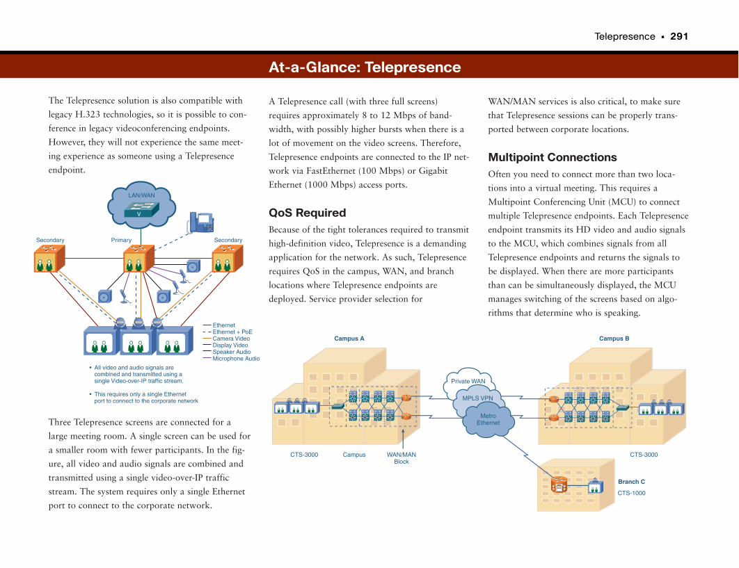
Telepresence • 291
The Telepresence solution is also compatible with
legacy H.323 technologies, so it is possible to con-
ference in legacy videoconferencing endpoints.
However, they will not experience the same meet-
ing experience as someone using a Telepresence
endpoint.
Three Telepresence screens are connected for a
large meeting room. A single screen can be used for
a smaller room with fewer participants. In the fig-
ure, all video and audio signals are combined and
transmitted using a single video-over-IP traffic
stream. The system requires only a single Ethernet
port to connect to the corporate network.
WAN/MAN services is also critical, to make sure
that Telepresence sessions can be properly trans-
ported between corporate locations.
Multipoint ConnectionsOften you need to connect more than two loca-
tions into a virtual meeting. This requires a
Multipoint Conferencing Unit (MCU) to connect
multiple Telepresence endpoints. Each Telepresence
endpoint transmits its HD video and audio signals
to the MCU, which combines signals from all
Telepresence endpoints and returns the signals to
be displayed. When there are more participants
than can be simultaneously displayed, the MCU
manages switching of the screens based on algo-
rithms that determine who is speaking.
A Telepresence call (with three full screens)
requires approximately 8 to 12 Mbps of band-
width, with possibly higher bursts when there is a
lot of movement on the video screens. Therefore,
Telepresence endpoints are connected to the IP net-
work via FastEthernet (100 Mbps) or Gigabit
Ethernet (1000 Mbps) access ports.
QoS RequiredBecause of the tight tolerances required to transmit
high-definition video, Telepresence is a demanding
application for the network. As such, Telepresence
requires QoS in the campus, WAN, and branch
locations where Telepresence endpoints are
deployed. Service provider selection for
At-a-Glance: Telepresence
EthernetEthernet + PoECamera VideoDisplay VideoSpeaker AudioMicrophone Audio
All video and audio signals arecombined and transmitted using a single Video-over-IP traffic stream.
This requires only a single Ethernetport to connect to the corporate network
•
•
PrimarySecondary Secondary
LAN/WAN
V
Campus A Campus B
Branch C
CTS-3000
CTS-1000
Campus WAN/MANBlock
CTS-3000
Private WAN
MPLS VPN
MetroEthernet

Presence and Location-Aware Services
I Sense a PresenceOne of the challenges with having so many communications options is that it
is sometimes difficult to know which forms of communication are available to
the person you want to call, at what times, and at what contact numbers. And
if multiple types are available, which do they prefer to be reached with?
Presence is about providing an integrated way for people to manage their dif-
ferent forms of communication. Using such information as which forms of
communication can be handled by the endpoint device currently being used,
what network resources the person has at his current location, and what the
recipient’s communication preferences are, presence helps connect people in
the most productive ways.
With personal settings, people can establish preferences for how they want to
be contacted. For example, when I am in a meeting, I can accept only instant
messages and e-mail, and when I am traveling I prefer to be contacted via
voice mail on my mobile phone.
The Importance of LocationLocation and presence are related. Location can help define what communica-
tions options are available to a person, and even which are appropriate. For
example, when a person is at her desk with access to high-speed wired net-
work services, she can accept almost any type of communication as long as the
device she is using supports it.
However, if the same person is traveling and using a handheld computer or
PDA/mobile phone, most likely she can’t accept video calls, and she may or
may not be able to participate in web conferencing for application sharing.
Location intelligence provided by the network can augment presence-based
applications. Location can also be used for other purposes, such as being able
to pinpoint the origination of a 911 call.
This technology is still in its early stages. It will continue to evolve and
improve through the next several years.
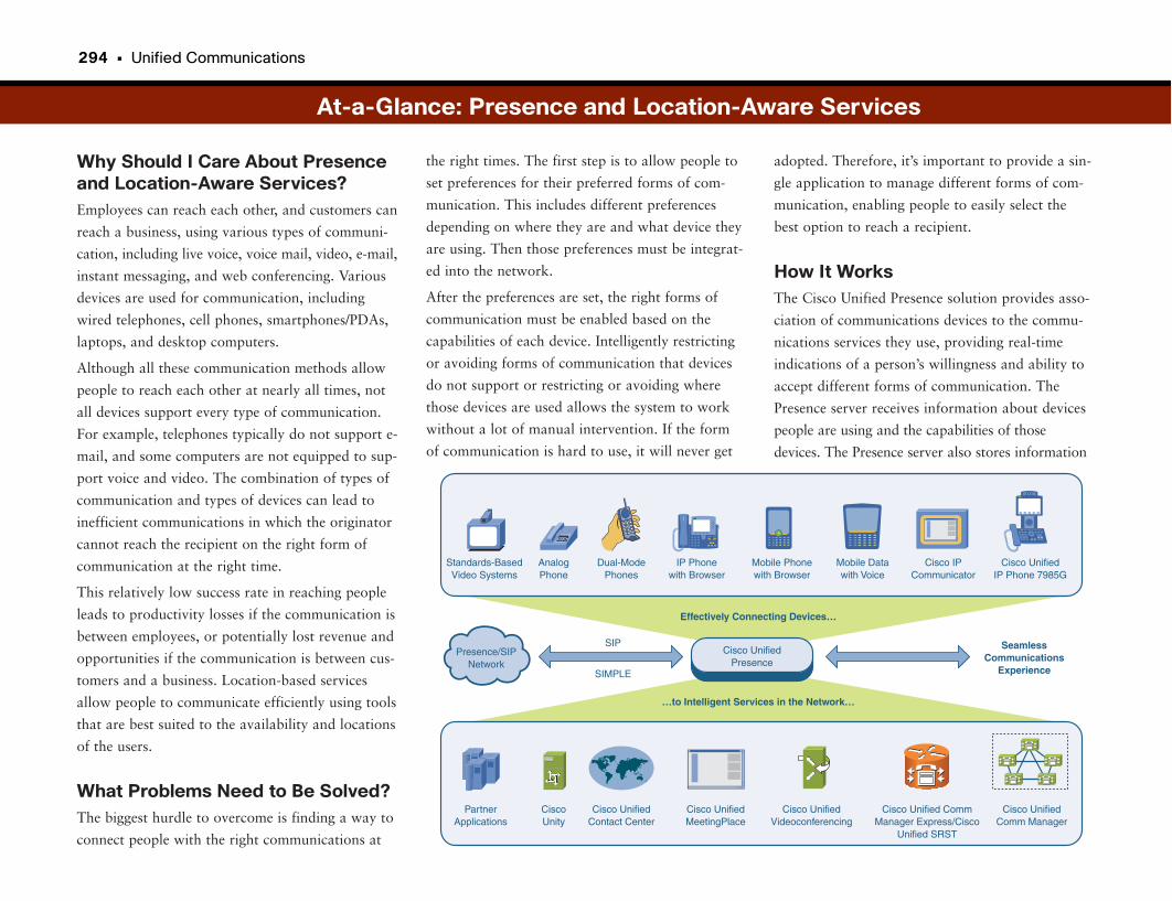
294 • Unified Communications
Why Should I Care About Presenceand Location-Aware Services?Employees can reach each other, and customers can
reach a business, using various types of communi-
cation, including live voice, voice mail, video, e-mail,
instant messaging, and web conferencing. Various
devices are used for communication, including
wired telephones, cell phones, smartphones/PDAs,
laptops, and desktop computers.
Although all these communication methods allow
people to reach each other at nearly all times, not
all devices support every type of communication.
For example, telephones typically do not support e-
mail, and some computers are not equipped to sup-
port voice and video. The combination of types of
communication and types of devices can lead to
inefficient communications in which the originator
cannot reach the recipient on the right form of
communication at the right time.
This relatively low success rate in reaching people
leads to productivity losses if the communication is
between employees, or potentially lost revenue and
opportunities if the communication is between cus-
tomers and a business. Location-based services
allow people to communicate efficiently using tools
that are best suited to the availability and locations
of the users.
What Problems Need to Be Solved?The biggest hurdle to overcome is finding a way to
connect people with the right communications at
adopted. Therefore, it’s important to provide a sin-
gle application to manage different forms of com-
munication, enabling people to easily select the
best option to reach a recipient.
How It WorksThe Cisco Unified Presence solution provides asso-
ciation of communications devices to the commu-
nications services they use, providing real-time
indications of a person’s willingness and ability to
accept different forms of communication. The
Presence server receives information about devices
people are using and the capabilities of those
devices. The Presence server also stores information
the right times. The first step is to allow people to
set preferences for their preferred forms of com-
munication. This includes different preferences
depending on where they are and what device they
are using. Then those preferences must be integrat-
ed into the network.
After the preferences are set, the right forms of
communication must be enabled based on the
capabilities of each device. Intelligently restricting
or avoiding forms of communication that devices
do not support or restricting or avoiding where
those devices are used allows the system to work
without a lot of manual intervention. If the form
of communication is hard to use, it will never get
At-a-Glance: Presence and Location-Aware Services
SeamlessCommunications
Experience
Cisco UnifiedPresence
CiscoUnity
PartnerApplications
Cisco UnifiedMeetingPlace
Cisco UnifiedContact Center
Cisco Unified CommManager Express/Cisco
Unified SRST
Cisco UnifiedVideoconferencing
AnalogPhone
Standards-BasedVideo Systems
IP Phonewith Browser
Dual-ModePhones
Mobile Datawith Voice
Mobile Phonewith Browser
Cisco IPCommunicator
Cisco UnifiedIP Phone 7985G
Cisco UnifiedComm Manager
Presence/SIPNetwork
SIP
SIMPLE
Effectively Connecting Devices…
…to Intelligent Services in the Network…
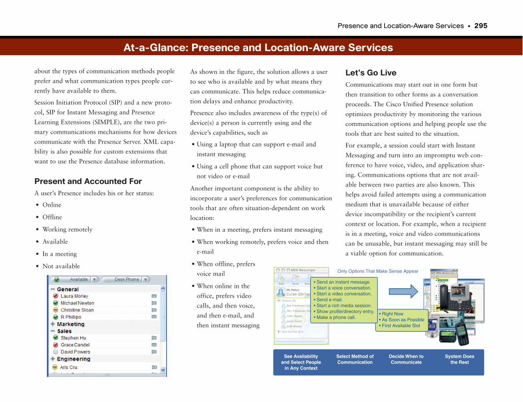
Presence and Location-Aware Services • 295
about the types of communication methods people
prefer and what communication types people cur-
rently have available to them.
Session Initiation Protocol (SIP) and a new proto-
col, SIP for Instant Messaging and Presence
Learning Extensions (SIMPLE), are the two pri-
mary communications mechanisms for how devices
communicate with the Presence Server. XML capa-
bility is also possible for custom extensions that
want to use the Presence database information.
Present and Accounted ForA user’s Presence includes his or her status:
• Online
• Offline
• Working remotely
• Available
• In a meeting
• Not available
Let’s Go LiveCommunications may start out in one form but
then transition to other forms as a conversation
proceeds. The Cisco Unified Presence solution
optimizes productivity by monitoring the various
communication options and helping people use the
tools that are best suited to the situation.
For example, a session could start with Instant
Messaging and turn into an impromptu web con-
ference to have voice, video, and application shar-
ing. Communications options that are not avail-
able between two parties are also known. This
helps avoid failed attempts using a communication
medium that is unavailable because of either
device incompatibility or the recipient’s current
context or location. For example, when a recipient
is in a meeting, voice and video communications
can be unusable, but instant messaging may still be
a viable option for communication.
As shown in the figure, the solution allows a user
to see who is available and by what means they
can communicate. This helps reduce communica-
tion delays and enhance productivity.
Presence also includes awareness of the type(s) of
device(s) a person is currently using and the
device’s capabilities, such as
• Using a laptop that can support e-mail and
instant messaging
• Using a cell phone that can support voice but
not video or e-mail
Another important component is the ability to
incorporate a user’s preferences for communication
tools that are often situation-dependent on work
location:
• When in a meeting, prefers instant messaging
• When working remotely, prefers voice and then
• When offline, prefers
voice mail
• When online in the
office, prefers video
calls, and then voice,
and then e-mail, and
then instant messaging
• Right Now• As Soon as Possible• First Available Slot
• Send an instant message.• Start a voice conversation.• Start a video conversation.• Send e-mail.• Start a rich media session.• Show profile/directory entry.• Make a phone call.
See Availabilityand Select People
in Any Context
Select Method ofCommunication
Decide When toCommunicate
Only Options That Make Sense Appear
System Doesthe Rest
At-a-Glance: Presence and Location-Aware Services
IP Call Center
Why Can’t I Talk to a Real Person?“Press 1 to use our automated attendant. Press 2 to speak with a representative.”
Customer service, support, and sales are sophisticated in how they handle and
direct calls to the appropriate representative. From an automated attendant
answering the phone, to the automated redirection of a call, to the interaction
of phone and computer applications, call-center applications allow a company
to efficiently and effectively manage customer calls. Although this setup is pos-
sible in traditional voice networks, the convergence of voice with IP networks
opens new possibilities and an ease of administration not previously available.
Anatomy of a Contact CenterWhether you call a computer company for support, an insurance company to
make a claim, or an airline to check the status of a flight, you interact with a
call center in some fashion. Likewise, when you receive a call during dinner
asking whether you want to subscribe to a newspaper, a call center is interact-
ing with you. The goal of a call center is to efficiently route a call to the
appropriate person or call service while managing call queues when there are
more calls than available call-center employees.
Here are the primary components of a contact center:
• Private branch exchange (PBX): Provides traditional call-handling
functionality.
• Interactive voice response (IVR): Affectionately known as “Silicon Sally,”
IVR is computer software that provides a series of audible menus for the
caller to interact with. The IVR interprets key presses and, more recently,
uses voice recognition to walk the caller through a series of menus. Based on
the caller’s selections, the IVR can return information to the user, ending the
call, or direct the call to an agent as appropriate.
• Automatic call distribution (ACD): Depending on the vendor, ACD provides
any of the following functionality:
— Call distribution based on customizable rules
— The ability to hold callers in a queue
— Music On Hold, customizable messages and advertisements that play
while the caller waits in a queue
• Computer telephony integration (CTI): Allows computer applications to
interface with the telephone equipment. For call centers, the caller’s phone
number, account number, or any piece of information the caller provides can
serve as the key for an application. For example, when a customer calls her
insurance company with questions, the call agent application can intercept
the calling phone number and automatically display the customer’s personal
account information to the insurance agent.
You can put all these components together in endless combinations; no two
call centers operate the same. Vendors provide the functionality described here
in different packaging and levels of functionality.
From the Caller to the Agent, and Back AgainContact centers can exist in many forms, but in general, a caller interacts with
one of two models: inbound or outbound. The goal is to redirect the call to
the appropriate live person or audible application that serves the caller. With
an inbound contact center, the customer initiates the call to the company.
Examples of inbound calls include contacting the following:
• An insurance company to make a claim
• An airline to check a flight schedule
• A bank for account information
• A computer company for technical support
• A mail-order company to make a purchase
• The power company to report an outage
A traditional ACD determines where to route the call. With an IP-based call
center, the IVR, intelligent contact management (ICM), and PBX are like a
virtual ACD. Generally, the caller interacts with an IVR first. The IVR replaces
the traditional switchboard operator or receptionist by giving the caller a list
of options. Based on the caller’s responses, the IVR either returns a code to
the ACD or runs an application that addresses the caller’s need. With the
298 • Unified Communications
application, the caller either receives the information he needs and hangs up or
interacts further. When the IVR returns a code, the ACD then determines
where to route the call, which might eventually be a group of call agents.
When managing calls destined for a group of agents, the ACD typically pro-
vides a series of functions that help manage a queue of callers. The caller
remains on hold, and he or she might hear music, status messages, or adver-
tisements while waiting in the queue. When an agent becomes available, the
ACD transfers the call to the PBX, finally linking the customer to a person.
With an IP call center, the IVR might serve as the queue point rather than the
traditional ACD. The other model, outbound, lets a system dial many numbers
and then transfer the call to a live agent after it finds a number to ring or a
person to answer. It appears that the agent called the caller directly. Examples
of this method include the following:
• Subscription solicitations from a local newspaper
• Special offers from insurance companies
• A public-opinion poll conducted by a political party
• A loan company pursuing delinquent customers
With this model, an outbound dialer device parses through lists of phone num-
bers and dials each one. Based on defined rules, the dialer device hands the call
to the ACD after it finds a live person, an answering machine, or simply a
ring. The ACD transfers the call to either an automated recording or a live
agent. The call then proceeds.
Generally, for both methods, time is of the essence. Callers become frustrated
and angry when forced to talk to recordings or sit in queues for any period of
time. So the various systems that make up the call center must be tightly inte-
grated and fast.
Managing Caller and Contact Agent EfficiencyAs companies conduct business across multiple time zones and countries, they
need to provide contact center services that do the following:
• Balance loads across multiple contact centers.
• Provide support wherever the sun is shining (around the globe).
• Allow contact agents to seamlessly work in remote locations. (You never
know where your call is actually directed, except perhaps from the accent of
the agent you interact with.)
New Methods for Customer InteractionThe Internet created new methods for customers and companies to interact.
Aside from the telephone, customers need to be able to contact a company
through the web and e-mail. Interactive web-based “chat”-type support is pop-
ular. As various industries adopt these additional contact methods, customers
begin to expect all other industry competitors to do so as well. To the cus-
tomer, it should not matter whether she uses e-mail, interactive chat, web sub-
mission, or the telephone: A company should respond with the same quality
and priority regardless of the method. For the company with a traditional
phone-based call center, migrating to this multiple-method model can be diffi-
cult.
Today’s IP-based contact-center software manages e-mail, phone calls, and
other contact methods all from the same set of tools.
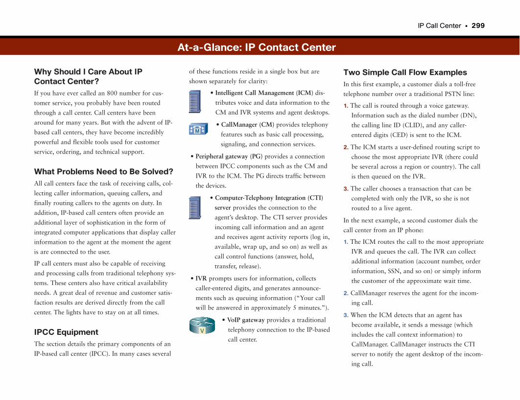
IP Call Center • 299
Why Should I Care About IP Contact Center?If you have ever called an 800 number for cus-
tomer service, you probably have been routed
through a call center. Call centers have been
around for many years. But with the advent of IP-
based call centers, they have become incredibly
powerful and flexible tools used for customer
service, ordering, and technical support.
What Problems Need to Be Solved?All call centers face the task of receiving calls, col-
lecting caller information, queuing callers, and
finally routing callers to the agents on duty. In
addition, IP-based call centers often provide an
additional layer of sophistication in the form of
integrated computer applications that display caller
information to the agent at the moment the agent
is are connected to the user.
IP call centers must also be capable of receiving
and processing calls from traditional telephony sys-
tems. These centers also have critical availability
needs. A great deal of revenue and customer satis-
faction results are derived directly from the call
center. The lights have to stay on at all times.
IPCC EquipmentThe section details the primary components of an
IP-based call center (IPCC). In many cases several
Two Simple Call Flow ExamplesIn this first example, a customer dials a toll-free
telephone number over a traditional PSTN line:
1. The call is routed through a voice gateway.
Information such as the dialed number (DN),
the calling line ID (CLID), and any caller-
entered digits (CED) is sent to the ICM.
2. The ICM starts a user-defined routing script to
choose the most appropriate IVR (there could
be several across a region or country). The call
is then queued on the IVR.
3. The caller chooses a transaction that can be
completed with only the IVR, so she is not
routed to a live agent.
In the next example, a second customer dials the
call center from an IP phone:
1. The ICM routes the call to the most appropriate
IVR and queues the call. The IVR can collect
additional information (account number, order
information, SSN, and so on) or simply inform
the customer of the approximate wait time.
2. CallManager reserves the agent for the incom-
ing call.
3. When the ICM detects that an agent has
become available, it sends a message (which
includes the call context information) to
CallManager. CallManager instructs the CTI
server to notify the agent desktop of the incom-
ing call.
of these functions reside in a single box but are
shown separately for clarity:
• Intelligent Call Management (ICM) dis-
tributes voice and data information to the
CM and IVR systems and agent desktops.
• CallManager (CM) provides telephony
features such as basic call processing,
signaling, and connection services.
• Peripheral gateway (PG) provides a connection
between IPCC components such as the CM and
IVR to the ICM. The PG directs traffic between
the devices.
• Computer-Telephony Integration (CTI)
server provides the connection to the
agent’s desktop. The CTI server provides
incoming call information and an agent
and receives agent activity reports (log in,
available, wrap up, and so on) as well as
call control functions (answer, hold,
transfer, release).
• IVR prompts users for information, collects
caller-entered digits, and generates announce-
ments such as queuing information (“Your call
will be answered in approximately 5 minutes.”).
• VoIP gateway provides a traditional
telephony connection to the IP-based
call center.
At-a-Glance: IP Contact Center
M
V
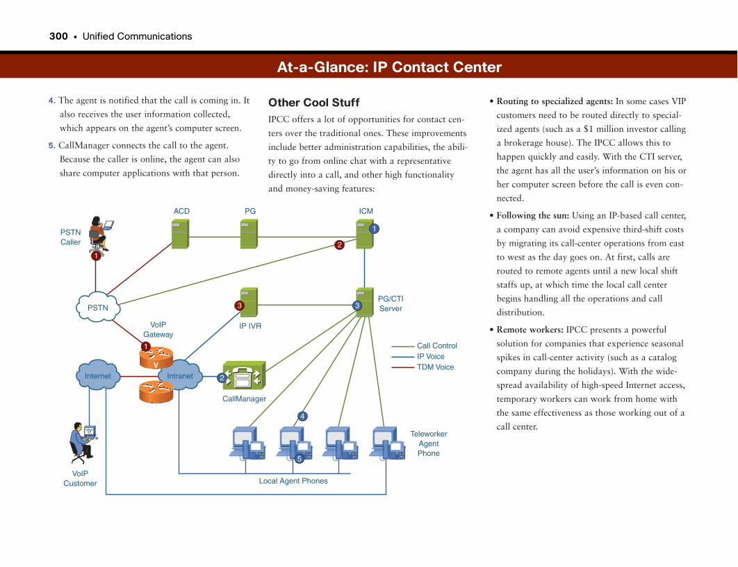
300 • Unified Communications
4. The agent is notified that the call is coming in. It
also receives the user information collected,
which appears on the agent’s computer screen.
5. CallManager connects the call to the agent.
Because the caller is online, the agent can also
share computer applications with that person.
• Routing to specialized agents: In some cases VIP
customers need to be routed directly to special-
ized agents (such as a $1 million investor calling
a brokerage house). The IPCC allows this to
happen quickly and easily. With the CTI server,
the agent has all the user’s information on his or
her computer screen before the call is even con-
nected.
• Following the sun: Using an IP-based call center,
a company can avoid expensive third-shift costs
by migrating its call-center operations from east
to west as the day goes on. At first, calls are
routed to remote agents until a new local shift
staffs up, at which time the local call center
begins handling all the operations and call
distribution.
• Remote workers: IPCC presents a powerful
solution for companies that experience seasonal
spikes in call-center activity (such as a catalog
company during the holidays). With the wide-
spread availability of high-speed Internet access,
temporary workers can work from home with
the same effectiveness as those working out of a
call center.
Other Cool StuffIPCC offers a lot of opportunities for contact cen-
ters over the traditional ones. These improvements
include better administration capabilities, the abili-
ty to go from online chat with a representative
directly into a call, and other high functionality
and money-saving features:
At-a-Glance: IP Contact Center
Call Control
PSTNCaller
VoIPCustomer
VoIPGateway
TeleworkerAgentPhone
Local Agent Phones
ACD PG ICM
IP IVR
PG/CTIServer
CallManager
Internet Intranet
PSTN
1
1
2
2
3 3
4
VIP VoiceTDM Voice
5
1
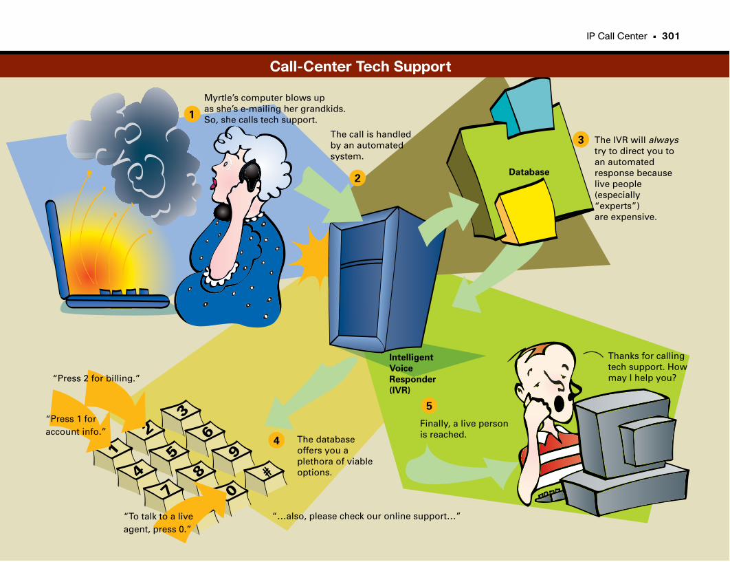
IP Call Center • 301
1
2
Myrtle’s computer blows up as she’s e-mailing her grandkids.So, she calls tech support.1
2
3
4
5
Intelligent
Voice
Responder
(IVR)
Database
The IVR will alwaystry to direct you to an automated response because live people (especially“experts”)are expensive.
“…also, please check our online support…”
“Press 1 foraccount info.”
“Press 2 for billing.”
“To talk to a liveagent, press 0.”
Thanks for callingtech support. How may I help you?
Finally, a live personis reached.
3
6
9
#
0
8
5
4
7
The call is handledby an automatedsystem.
The databaseoffers you a plethora of viableoptions.
Call-Center Tech Support
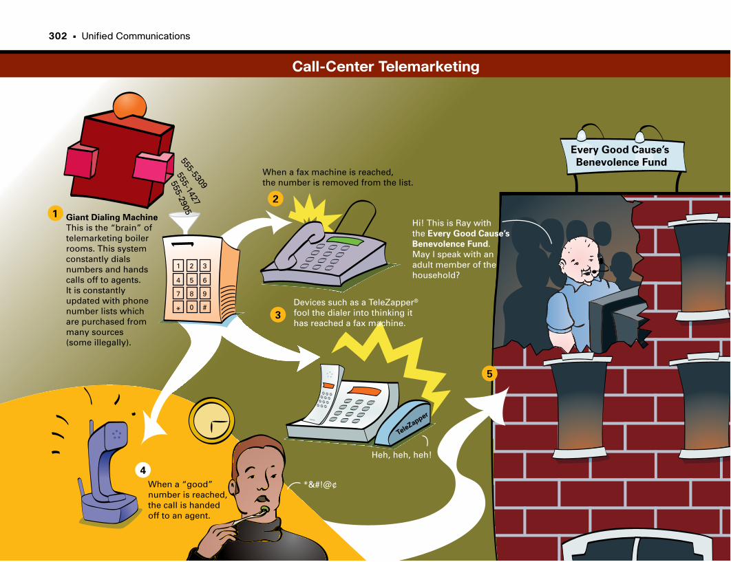
1
2
3
4
5
Giant Dialing Machine
This is the “brain” of telemarketing boilerrooms. This system constantly dials numbers and handscalls off to agents.It is constantlyupdated with phonenumber lists whichare purchased from many sources (some illegally).
Hi! This is Ray with the Every Good Cause’s
Benevolence Fund.May I speak with anadult member of the household?
When a fax machine is reached, the number is removed from the list.
Devices such as a TeleZapper®
fool the dialer into thinking it has reached a fax machine.
Heh, heh, heh!
*&#!@¢When a “good” number is reached, the call is handedoff to an agent.
555-5309
555-1427
555-2905
1 2 3
4 5 6
7 8 9
* 0 #
TeleZapper
Every Good Cause’s
Benevolence Fund
Call-Center Telemarketing
302 • Unified Communications

This page intentionally left blank
Multicast and IPTV Broadcasts
Watching Movies Without Flooding the WorldIP multicast is a bandwidth-conserving technology based on IP in which data
intended for multiple receivers is efficiently transmitted with a single stream. IP
multicast best serves streaming audio, video, and data applications such as
software distribution or stock-quote broadcasts.
Consider this example: A corporate officer needs to deliver a live video broad-
cast to the company’s employees. Doing so across an IP network using tradi-
tional IP protocols would require that the video feed be replicated once for
every user. For a branch office across a WAN link, 20 employees watching the
video on their computers would result in the video stream being replicated 20
times across the WAN. Not only is this highly inefficient, but the typical WAN
link could not handle the amount of traffic being transmitted. IP multicast
protocols allow users to request a particular multicast service (which can be
audio, video, or data). The network then determines the source of the multi-
cast transmission and routes the multicast stream to its destination.
Multicast protocols ensure that only one copy of the stream is transmitted
across any given link. Therefore, in the preceding branch-office example, only
one copy of the video broadcast would be transmitted over the WAN and then
would be replicated to each user at the LAN level. Multicasts relate to the con-
cept of a group. The receivers who express an interest in receiving a particular
data stream define the group. A receiver must join the group by using Internet
Group Management Protocol (IGMP), which requires that routers and switch-
es must support IGMP to communicate with the receiver (application). Not
until the receiver joins the group can she receive the data stream.
A multicast IP address identifies a group. The Internet Assigned Numbers
Authority (IANA) assigns multicast IP addresses using the IP Class D address
space of 224.0.0.0 to 239.255.255.255. The routers in a network are responsi-
ble for identifying the shortest, most efficient path from the multicast transmit-
ter to its group of receivers. The Layer 2 LAN switches are responsible for
receiving the singular transmission and replicating it to each of the registered
receivers. Of the multicast-related routing protocols, the primary protocol is
Protocol-Independent Multicast (PIM). The routers use PIM to make forward-
ing decisions. PIM determines the shortest path for each multicast group based
on the IP routing protocol running on the router (such as Enhanced Interior
Gateway Routing Protocol [EIGRP] or Open Shortest Path First [OSPF]).
Using Reverse Path Forwarding (RPF), routers use the existing unicast routing
table to determine upstream and downstream neighbors and eliminate any
loops. PIM operates in three different modes: sparse, dense, and sparse-dense.
The mode determines when the routers start forwarding packets to the group.
Sparse mode employs a “pull” model, and dense mode uses a “push” model.
In sparse mode, packets are not transmitted through the network until a
receiver specifically asks to join the group.
In dense mode, packets are transmitted throughout the network without
regard for registered users, and the network prunes transmission to parts of
the network where no receivers are registered. Sparse mode is more efficient in
that traffic goes only where requested, whereas dense mode blasts everywhere
initially.
The third mode is sparse-dense mode (developed by Cisco), in which the net-
work intelligently determines which mode to use as opposed to just configur-
ing one or the other. Sparse mode generally is implemented for standard video
and audio transmission in corporate networks.
A core component of a sparse implementation is the rendezvous point (RP).
The RP is the central clearinghouse for multicast transmitters and group
receivers. Multicast transmitters register themselves with the RP, and the net-
work forwards requests from group receivers to the RP. The RP then facilitates
the transmission of the data stream to the receivers. If the RP fails or disap-
pears from the network, receivers cannot register with senders. Therefore, a
network needs multiple RPs. Anycast-RP is a protocol based on Multicast
Source Discovery Protocol (MSDP) that facilitates the fault-tolerant implemen-
tation of multiple RPs.
306 • Unified Communications
Dense mode floods traffic to every corner of the network. This brute-force
method makes sense only when there are receivers on every subnet in a net-
work. After traffic begins flowing, routers stop the flow of (or prune) traffic to
subnets that have no receivers. Companies generally do not implement dense
mode except for special circumstances because of its fire-hose approach to
data-stream replication.
Although PIM makes sense in a corporate network, it requires that a network
be planned and configured to handle the particular implementation of PIM
properly. This setup is impractical across the Internet and shared IP networks
for which there is no guarantee that multicast is configured consistently or
properly. Multiprotocol Border Gateway Protocol (MBGP) allows the scalable
advertising and transmission of MBGP routes through the Internet.
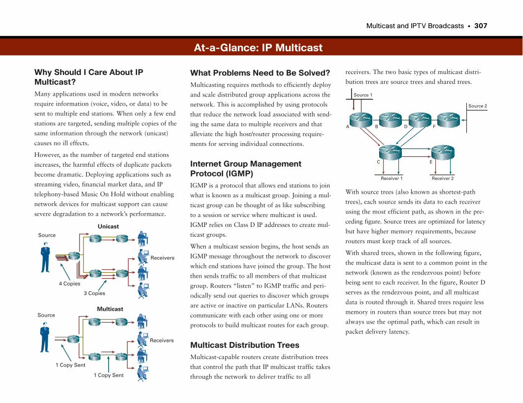
Multicast and IPTV Broadcasts • 307
Why Should I Care About IPMulticast?Many applications used in modern networks
require information (voice, video, or data) to be
sent to multiple end stations. When only a few end
stations are targeted, sending multiple copies of the
same information through the network (unicast)
causes no ill effects.
However, as the number of targeted end stations
increases, the harmful effects of duplicate packets
become dramatic. Deploying applications such as
streaming video, financial market data, and IP
telephony-based Music On Hold without enabling
network devices for multicast support can cause
severe degradation to a network’s performance.
receivers. The two basic types of multicast distri-
bution trees are source trees and shared trees.
With source trees (also known as shortest-path
trees), each source sends its data to each receiver
using the most efficient path, as shown in the pre-
ceding figure. Source trees are optimized for latency
but have higher memory requirements, because
routers must keep track of all sources.
With shared trees, shown in the following figure,
the multicast data is sent to a common point in the
network (known as the rendezvous point) before
being sent to each receiver. In the figure, Router D
serves as the rendezvous point, and all multicast
data is routed through it. Shared trees require less
memory in routers than source trees but may not
always use the optimal path, which can result in
packet delivery latency.
What Problems Need to Be Solved?Multicasting requires methods to efficiently deploy
and scale distributed group applications across the
network. This is accomplished by using protocols
that reduce the network load associated with send-
ing the same data to multiple receivers and that
alleviate the high host/router processing require-
ments for serving individual connections.
Internet Group ManagementProtocol (IGMP)IGMP is a protocol that allows end stations to join
what is known as a multicast group. Joining a mul-
ticast group can be thought of as like subscribing
to a session or service where multicast is used.
IGMP relies on Class D IP addresses to create mul-
ticast groups.
When a multicast session begins, the host sends an
IGMP message throughout the network to discover
which end stations have joined the group. The host
then sends traffic to all members of that multicast
group. Routers “listen” to IGMP traffic and peri-
odically send out queries to discover which groups
are active or inactive on particular LANs. Routers
communicate with each other using one or more
protocols to build multicast routes for each group.
Multicast Distribution TreesMulticast-capable routers create distribution trees
that control the path that IP multicast traffic takes
through the network to deliver traffic to all
4 Copies
3 Copies
Unicast
Receivers
Source
At-a-Glance: IP Multicast
Multicast
1 Copy Sent
1 Copy Sent
Receivers
Source
Source 1
Source 2
Receiver 1 Receiver 2
C E
A B FD
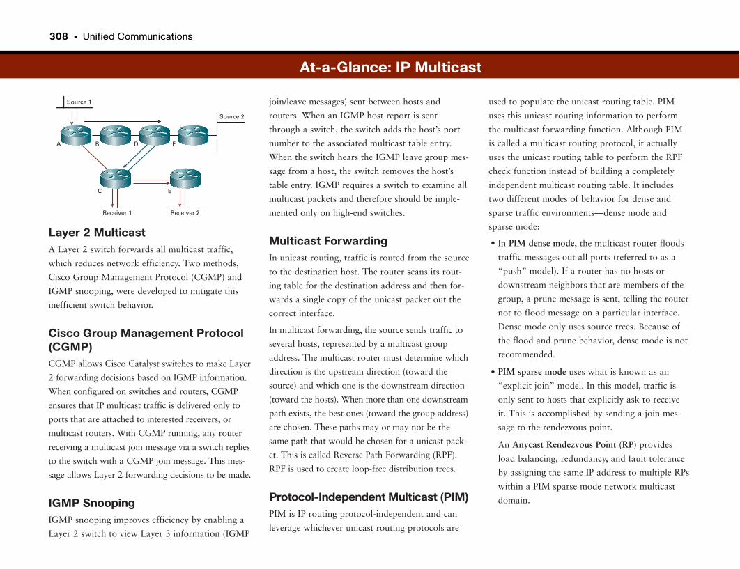
308 • Unified Communications
Layer 2 MulticastA Layer 2 switch forwards all multicast traffic,
which reduces network efficiency. Two methods,
Cisco Group Management Protocol (CGMP) and
IGMP snooping, were developed to mitigate this
inefficient switch behavior.
Cisco Group Management Protocol(CGMP)CGMP allows Cisco Catalyst switches to make Layer
2 forwarding decisions based on IGMP information.
When configured on switches and routers, CGMP
ensures that IP multicast traffic is delivered only to
ports that are attached to interested receivers, or
multicast routers. With CGMP running, any router
receiving a multicast join message via a switch replies
to the switch with a CGMP join message. This mes-
sage allows Layer 2 forwarding decisions to be made.
IGMP SnoopingIGMP snooping improves efficiency by enabling a
Layer 2 switch to view Layer 3 information (IGMP
used to populate the unicast routing table. PIM
uses this unicast routing information to perform
the multicast forwarding function. Although PIM
is called a multicast routing protocol, it actually
uses the unicast routing table to perform the RPF
check function instead of building a completely
independent multicast routing table. It includes
two different modes of behavior for dense and
sparse traffic environments—dense mode and
sparse mode:
• In PIM dense mode, the multicast router floods
traffic messages out all ports (referred to as a
“push” model). If a router has no hosts or
downstream neighbors that are members of the
group, a prune message is sent, telling the router
not to flood message on a particular interface.
Dense mode only uses source trees. Because of
the flood and prune behavior, dense mode is not
recommended.
• PIM sparse mode uses what is known as an
“explicit join” model. In this model, traffic is
only sent to hosts that explicitly ask to receive
it. This is accomplished by sending a join mes-
sage to the rendezvous point.
An Anycast Rendezvous Point (RP) provides
load balancing, redundancy, and fault tolerance
by assigning the same IP address to multiple RPs
within a PIM sparse mode network multicast
domain.
join/leave messages) sent between hosts and
routers. When an IGMP host report is sent
through a switch, the switch adds the host’s port
number to the associated multicast table entry.
When the switch hears the IGMP leave group mes-
sage from a host, the switch removes the host’s
table entry. IGMP requires a switch to examine all
multicast packets and therefore should be imple-
mented only on high-end switches.
Multicast ForwardingIn unicast routing, traffic is routed from the source
to the destination host. The router scans its rout-
ing table for the destination address and then for-
wards a single copy of the unicast packet out the
correct interface.
In multicast forwarding, the source sends traffic to
several hosts, represented by a multicast group
address. The multicast router must determine which
direction is the upstream direction (toward the
source) and which one is the downstream direction
(toward the hosts). When more than one downstream
path exists, the best ones (toward the group address)
are chosen. These paths may or may not be the
same path that would be chosen for a unicast pack-
et. This is called Reverse Path Forwarding (RPF).
RPF is used to create loop-free distribution trees.
Protocol-Independent Multicast (PIM)PIM is IP routing protocol-independent and can
leverage whichever unicast routing protocols are
At-a-Glance: IP Multicast
Source 1
Source 2
Receiver 1 Receiver 2
C E
A B FD
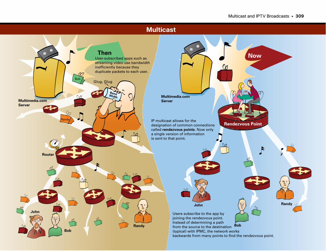
Multicast and IPTV Broadcasts • 309
Multimedia.com
Server
Multimedia.com
Server
ThenNow
Bob
John
Randy
Router
Glug, Glug
User-subscribed apps such as streaming video use bandwidthinefficiently because they duplicate packets to each user.
IP multicast allows for the designation of common connectionscalled rendezvous points. Now onlya single version of informationis sent to that point.
BandWidth
John
Bob
Randy
John
Bob
Randy
Rendezvous Point
Users subscribe to the app by joining the rendezvous point.Instead of determining a path from the source to the destination(typical) with IPMC, the network works backwards from many points to find the rendezvous point.
Multicast

Part VIII
Mobility
Wireless WorldAt this point, you should have enough information to understand how networking works. For the most
part, smart IT people can wire together all the networks and connect all the devices to the switches and
the routers and the data centers and light it all up and make it go. There’s only one slight problem. We
have decided (after most of this connecting stuff took place) that we really don’t like those wires. Hmmm.
Back to square one.
This section focuses on wireless networking, which adds a whole new dimension and, as you will see, a
whole new set of design considerations and challenges. Because we are back to basics, we will go back to
the LAN or, in this case, wireless LAN [WLAN]. “Selecting and Building Wireless Networks” takes a look
at basic wireless design from the perspective of the IT staff. As you will see, there is a lot more to it than
just plugging in a couple of wireless routers.
One of the biggest considerations and concerns with wireless networking is security. In fact, wireless secu-
rity was and is such a concern that it still has a big impact on companies choosing whether to adopt or
allow wireless networking. The next section looks at why wireless security is such a concern and how
these issues are resolved.
The first three topics in this section cover just the basics, but it turns out that users want and sometimes
demand more. The fourth topic in this section looks at one extension of basic wireless networking—hav-
ing city-wide wireless access. Also called municipal or muni wireless, more and more cities are deploying
this type of service.
We follow with another new adaptation of wireless, voice over IP (VoIP) over wireless networks. This
technology presents quite a few challenges that must be overcome, but after they are solved, significant
productivity gains can be enjoyed. Of all the technologies discussed in this book so far, wireless VoIP is
potentially one of the more challenging technologies for IT staffers. A much simpler but no less important
wireless technology is guest access. It gives visitors Internet access in a way that does not compromise
internal network security.
This section closes with an interesting operational use of wireless: using the wireless system to locate and
track company assets. More and more companies, especially those with a lot of physical assets, are find-
ing that Radio Frequency Identification (RFID) and location-based services are a great way to keep an eye
on their stuff.
Mobility and Wireless Networks 313
Selecting and Building 319Wireless Networks
Securing Wireless Networks 325
Outdoor and Municipal 331Wireless Networks
VoIP over Wireless Networks 337
Wireless Guest Access 343
RFID and Location-Based Services 347
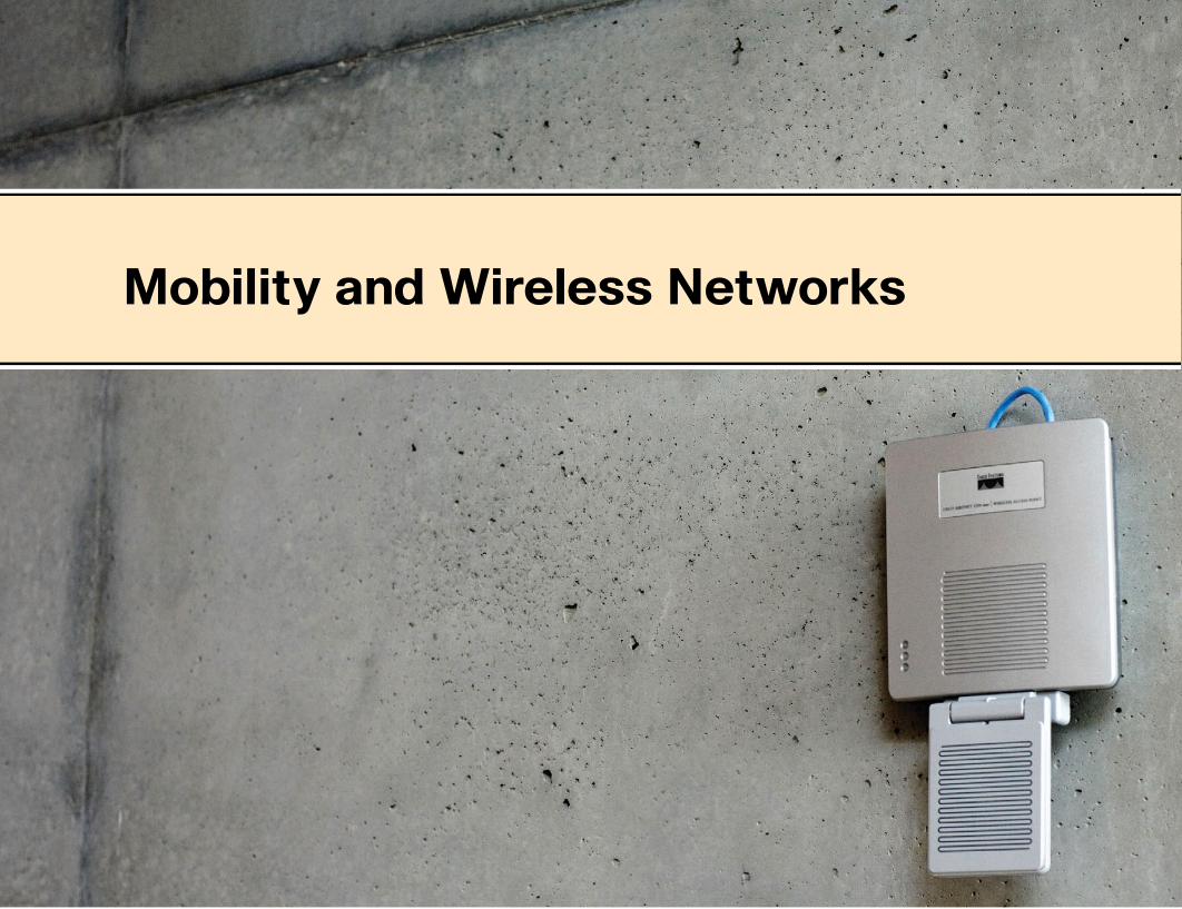
Mobility and Wireless Networks

• It is easier to collaborate on the spot. Users can exchange files or handle
requests for information when in meetings, for example.
• Users can exchange data with servers directly rather than wait to download
it from a wired connection. Users can also continue to exchange data with
servers while they move across the campus or warehouse. This flexibility is
important in warehouses and manufacturing, for example.
WLANs are meant to complement existing wired networks. Wireless access
points (similar to traditional Ethernet hubs) provide access to devices that have
wireless network interface cards. The access points connect to an Ethernet
switch and typically are configured on their own VLAN. Wireless bridges can
provide wireless connectivity as well. This setup allows for longer-distance
connectivity between buildings, for example. The current WLAN (Wi-Fi) stan-
dards include 802.11a, 802.11b, 802.11g, and the newly arrived 802.11n,
which offers unprecedented range and speed.
In general, WLANs cannot achieve speeds quite as fast as wired networks
(although they are getting pretty close). The size and orientation of the anten-
na, the transmission power setting, and the existence of obstructions (such as
walls or trees) determine the distance, speed, and coverage area between the
transmitter and receiver. If you must achieve connectivity at greater distances,
you can reduce the data rate or jack up the power. With Wi-Fi, trade-offs
occur between greater distance and faster transmission speeds.
Home wireless networks are based on the same Wi-Fi standards as corporate
wireless networks. For a more thorough discussion of wireless networks in the
home, pick up a copy of Wireless Home Networking Simplified (Cisco Press,
2006).
Throwing Away the Ties That BindThe evolution of the telephone reveals one consistent evolving design principle:
People do not want to be tied to a particular location when using the phone.
The first phones were attached to the wall, and people leaned down or stood
on their toes to speak into the horn and listen to the response. Then the
mouthpiece and listening device were combined into a single handset and con-
nected to the phone by a cord. The phone still hung on the wall, but you could
rest the handset against your head and talk to the other person comfortably.
Finally, the phone was liberated from the wall. A cable attached to the phone
itself allowed the caller to comfortably move the phone around the room. The
caller was still restricted by the length of the phone cable, but at least she
could lie on the couch while talking to a friend.
Then came cordless phones. The caller could be anywhere in the house, or
even in the garden, and still comfortably speak with friends and family. This
change was revolutionary in the independence it provided.
This same principle of independence applies to WLANs. Notebook computers
and personal digital assistants (PDA) are commonplace in corporations. People
take their computers with them to meetings, customer sites, airports, and
hotels.
Until recently, this mobility meant dragging a cable and being restricted to sit-
ting somewhere near the wall where the cable plugged into the network. With
wireless networking, the computer user can easily access the network wherever
he is as long as a wireless access point (AP) is nearby. Breaking the dependence
on a cable and a wall jack is quite liberating.
Some benefits realized with the introduction of wireless networking include the
following:
• Computer users can access the corporate network and Internet anywhere on
campus. This offers unprecedented convenience, flexibility, and productivity.
• Temporary networks are easier to set up when making moves, additions,
and changes or when setting up war rooms or temporary work spaces.
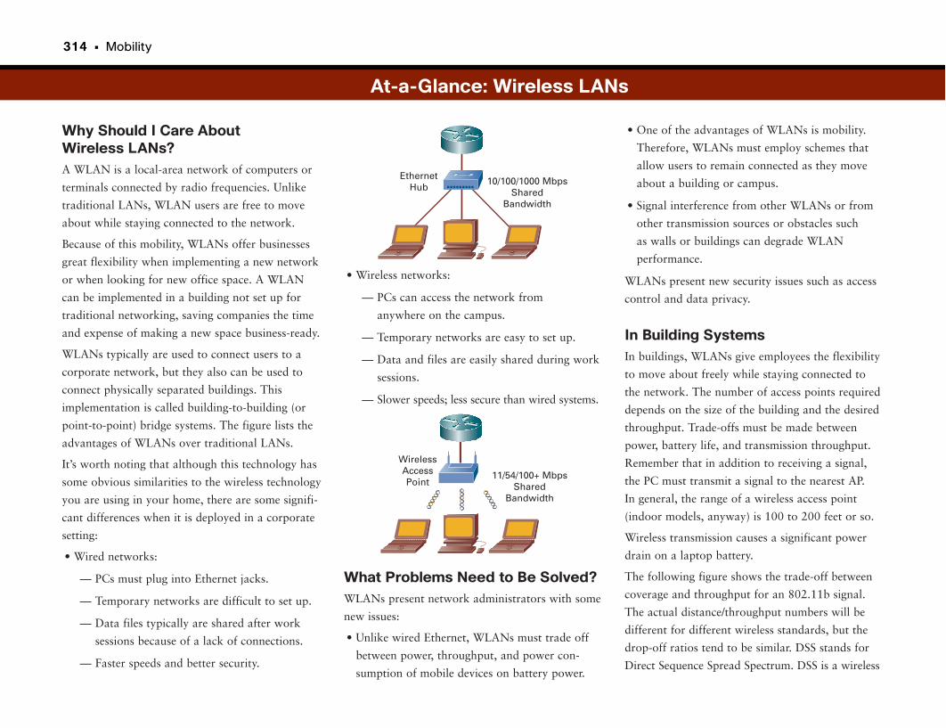
314 • Mobility
Why Should I Care About Wireless LANs?A WLAN is a local-area network of computers or
terminals connected by radio frequencies. Unlike
traditional LANs, WLAN users are free to move
about while staying connected to the network.
Because of this mobility, WLANs offer businesses
great flexibility when implementing a new network
or when looking for new office space. A WLAN
can be implemented in a building not set up for
traditional networking, saving companies the time
and expense of making a new space business-ready.
WLANs typically are used to connect users to a
corporate network, but they also can be used to
connect physically separated buildings. This
implementation is called building-to-building (or
point-to-point) bridge systems. The figure lists the
advantages of WLANs over traditional LANs.
It’s worth noting that although this technology has
some obvious similarities to the wireless technology
you are using in your home, there are some signifi-
cant differences when it is deployed in a corporate
setting:
• Wired networks:
— PCs must plug into Ethernet jacks.
— Temporary networks are difficult to set up.
— Data files typically are shared after work
sessions because of a lack of connections.
— Faster speeds and better security.
• One of the advantages of WLANs is mobility.
Therefore, WLANs must employ schemes that
allow users to remain connected as they move
about a building or campus.
• Signal interference from other WLANs or from
other transmission sources or obstacles such
as walls or buildings can degrade WLAN
performance.
WLANs present new security issues such as access
control and data privacy.
In Building SystemsIn buildings, WLANs give employees the flexibility
to move about freely while staying connected to
the network. The number of access points required
depends on the size of the building and the desired
throughput. Trade-offs must be made between
power, battery life, and transmission throughput.
Remember that in addition to receiving a signal,
the PC must transmit a signal to the nearest AP.
In general, the range of a wireless access point
(indoor models, anyway) is 100 to 200 feet or so.
Wireless transmission causes a significant power
drain on a laptop battery.
The following figure shows the trade-off between
coverage and throughput for an 802.11b signal.
The actual distance/throughput numbers will be
different for different wireless standards, but the
drop-off ratios tend to be similar. DSS stands for
Direct Sequence Spread Spectrum. DSS is a wireless
• Wireless networks:
— PCs can access the network from
anywhere on the campus.
— Temporary networks are easy to set up.
— Data and files are easily shared during work
sessions.
— Slower speeds; less secure than wired systems.
What Problems Need to Be Solved?WLANs present network administrators with some
new issues:
• Unlike wired Ethernet, WLANs must trade off
between power, throughput, and power con-
sumption of mobile devices on battery power.
At-a-Glance: Wireless LANs
EthernetHub
10/100/1000 MbpsShared
Bandwidth
11/54/100+ MbpsShared
Bandwidth
WirelessAccessPoint
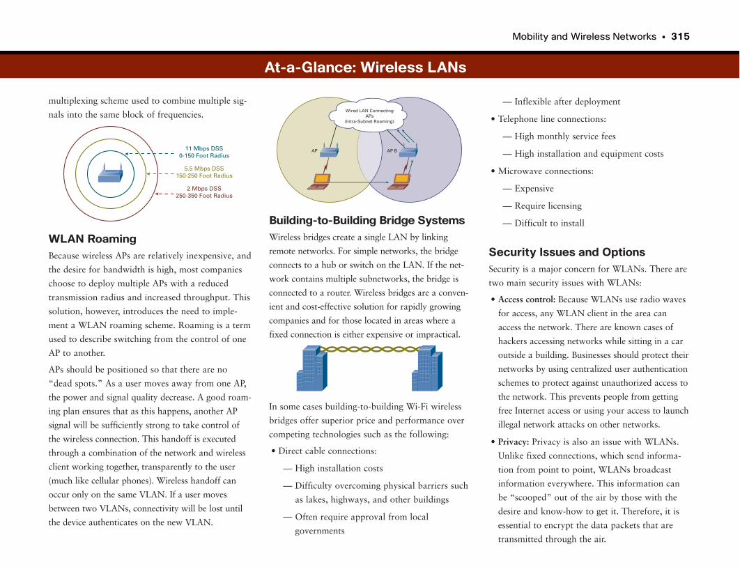
Mobility and Wireless Networks • 315
multiplexing scheme used to combine multiple sig-
nals into the same block of frequencies.
WLAN RoamingBecause wireless APs are relatively inexpensive, and
the desire for bandwidth is high, most companies
choose to deploy multiple APs with a reduced
transmission radius and increased throughput. This
solution, however, introduces the need to imple-
ment a WLAN roaming scheme. Roaming is a term
used to describe switching from the control of one
AP to another.
APs should be positioned so that there are no
“dead spots.” As a user moves away from one AP,
the power and signal quality decrease. A good roam-
ing plan ensures that as this happens, another AP
signal will be sufficiently strong to take control of
the wireless connection. This handoff is executed
through a combination of the network and wireless
client working together, transparently to the user
(much like cellular phones). Wireless handoff can
occur only on the same VLAN. If a user moves
between two VLANs, connectivity will be lost until
the device authenticates on the new VLAN.
— Inflexible after deployment
• Telephone line connections:
— High monthly service fees
— High installation and equipment costs
• Microwave connections:
— Expensive
— Require licensing
— Difficult to install
Security Issues and OptionsSecurity is a major concern for WLANs. There are
two main security issues with WLANs:
• Access control: Because WLANs use radio waves
for access, any WLAN client in the area can
access the network. There are known cases of
hackers accessing networks while sitting in a car
outside a building. Businesses should protect their
networks by using centralized user authentication
schemes to protect against unauthorized access to
the network. This prevents people from getting
free Internet access or using your access to launch
illegal network attacks on other networks.
• Privacy: Privacy is also an issue with WLANs.
Unlike fixed connections, which send informa-
tion from point to point, WLANs broadcast
information everywhere. This information can
be “scooped” out of the air by those with the
desire and know-how to get it. Therefore, it is
essential to encrypt the data packets that are
transmitted through the air.
Building-to-Building Bridge SystemsWireless bridges create a single LAN by linking
remote networks. For simple networks, the bridge
connects to a hub or switch on the LAN. If the net-
work contains multiple subnetworks, the bridge is
connected to a router. Wireless bridges are a conven-
ient and cost-effective solution for rapidly growing
companies and for those located in areas where a
fixed connection is either expensive or impractical.
In some cases building-to-building Wi-Fi wireless
bridges offer superior price and performance over
competing technologies such as the following:
• Direct cable connections:
— High installation costs
— Difficulty overcoming physical barriers such
as lakes, highways, and other buildings
— Often require approval from local
governments
Wired LAN ConnectingAPs
(Intra-Subnet Roaming)
AP AP B
At-a-Glance: Wireless LANs
2 Mbps DSS250-350 Foot Radius
5.5 Mbps DSS150-250 Foot Radius
11 Mbps DSS0-150 Foot Radius
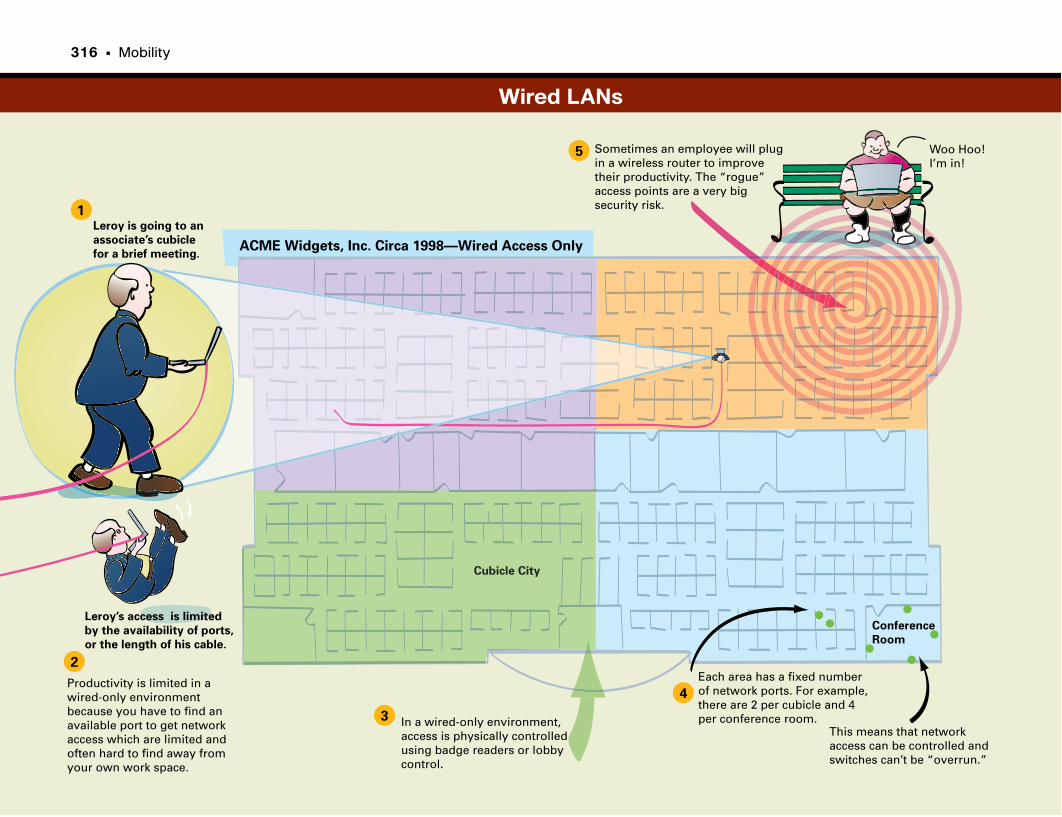
Woo Hoo!I’m in!
Sometimes an employee will plug in a wireless router to improve their productivity. The “rogue” access points are a very big security risk.
Each area has a fixed numberof network ports. For example, there are 2 per cubicle and 4 per conference room.In a wired-only environment,
access is physically controlledusing badge readers or lobby control.
Productivity is limited in a wired-only environmentbecause you have to find anavailable port to get networkaccess which are limited andoften hard to find away from your own work space.
This means that networkaccess can be controlled andswitches can’t be “overrun.”
Conference
Room
Cubicle City
ACME Widgets, Inc. Circa 1998—Wired Access Only
1
2
3
4
5
Leroy is going to an
associate’s cubicle
for a brief meeting.
Leroy’s access is limited
by the availability of ports,
or the length of his cable.
Wired LANs
316 • Mobility
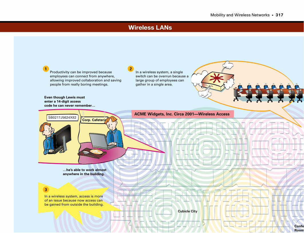
Mobility and Wireless Networks • 317
Corp. Cafeteria
Confe
Room
Cubicle City
ACME Widgets, Inc. Circa 2001—Wireless Access
1 2
3
Productivity can be improved because employees can connect from anywhere,allowing improved collaboration and savingpeople from really boring meetings.
SB0217J5624X82
…he’s able to work almost
anywhere in the building.
In a wireless system, a singleswitch can be overrun because a large group of employees cangather in a single area.
Even though Lewis must
enter a 14-digit access
code he can never remember…
In a wireless system, access is more of an issue because now access canbe gained from outside the building.
Wireless LANs
Selecting and Building Wireless Networks
Designing a Wireless NetworkAlthough it may seem a bit trivial to the casual user whose idea of assembling
a wireless network is connecting his Linksys router to his cable modem,
designing a wireless network on a corporate scale takes real engineering skill
and effort.
Some key considerations must be addressed; they are quite different from what
is involved in implementing a wired network. The first of these is which wire-
less standard is to be used. There are several, each of which has pros and cons.
Another consideration is where signal coverage will be (and not be, for that
matter). For example, a company may want to allow access to reach to an out-
door eating area, but not reach across a street or into another building for
security or interference reasons. Site planning must also be done to ensure that
no interference occurs between APs within the same system, requiring the same
type of planning required for cellular networks.
Another key consideration, and one that was never a problem for wired net-
works, is spontaneous system overloading. To see why this is a problem,
remember that the network was designed with a fixed number of ports
assigned to each switch. Let’s say, for example, that one switch typically covers
50 cubicles and offices, each with two ports, and ten meeting rooms, each
with ten switch ports. That’s 200 ports per switch and a maximum of 200
devices that can access the network from that switch. Because cubicles typical-
ly do not appear out of thin air, it’s not likely that any one switch will be over-
run with users.
Wireless, however, does not have this built-in safeguard. Imagine an “all
hands” corporate presentation in a large conference hall, which is covered by a
single access point. What happens during the break, when 250 employees all
decide to open their laptops and check their e-mail? Without some situational
planning, the IT department could be in for some long days.
The good news is that over the years, and through trial and error, some best
practices have been developed. They make the design process much easier on
both the IT department and the users.

320 • Mobility
Why Should I Care About Wireless Design?As employees rely more on mobility in the workplace to increase productivity,
wireless access is a critical part of any network. Productivity gains due to wire-
less access are estimated to be 30 percent or more, as employees use wireless
access in meeting rooms, hotspots, and other areas lacking wired access.
Wireless access to e-mail, corporate applications, and collaboration applica-
tions is now a minimum expectation by employees. Without it, they feel at a
disadvantage. Companies that do not provide wireless access for their employ-
ees (and even their guests) will find themselves under pressure from competi-
tors that do leverage the technology.
They may also have a higher instance of employees connecting their own wire-
less access points into live Ethernet ports, which creates a security risk. This is
called the “rogue” access point problem.
What Problems Need to Be Solved?Selecting a wireless network model that serves the needs of both the company
and its employees is a critical part of any deployment. Performance is also key,
because wireless users expect to have the same level of service, and access to
the same applications, as wired clients.
From an IT perspective, the deployment must provide a balance of adequate
coverage and service levels with deployment and operational costs. Finally, a
unified wireless solution must meet the needs of different wireless and mobility
services, now and in the future.
At-a-Glance: Designing Wi-Fi Networks
RFDomain
Mesh AccessPoint
Cisco2800/3700/3800
with WLANControllerModule
CiscoCatalyst 3750G
IntegratedWireless
LAN Controller
Large Branch Office
DataPlane
ControlPlane
ManagementPlane
Small/Medium Office Remote Office Outdoor Environment
REAP
LWAPP
LWAPP LWAPP
LWAPP
LWAPP
LWAPP
LWAPP
LWAPP
LWAPP
Browser-BasedRemote Consolefor Cisco WCS
Cisco WirelessControl System
(WCS)
Cisco WirelessLocation
Appliance
Catalyst 6500Series WiSM
Transmit Power Interference Detection/AvoidanceRogue Detection/Containment
Radio Resource Management Software
User Load Management Coverage Hole Management
Automatic Channel Management Mobility Management
Third-Party IntegratedApplications: E911,
Asset Tracking, ERP,Workflow Automation
Cisco Unified Wireless Architecture
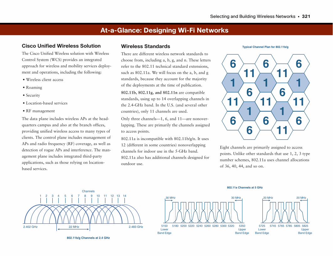
Selecting and Building Wireless Networks • 321
Cisco Unified Wireless SolutionThe Cisco Unified Wireless solution with Wireless
Control System (WCS) provides an integrated
approach for wireless and mobility services deploy-
ment and operations, including the following:
• Wireless client access
• Roaming
• Security
• Location-based services
• RF management
The data plane includes wireless APs at the head-
quarters campus and also at the branch offices,
providing unified wireless access to many types of
clients. The control plane includes management of
APs and radio frequency (RF) coverage, as well as
detection of rogue APs and interference. The man-
agement plane includes integrated third-party
applications, such as those relying on location-
based services.
Eight channels are primarily assigned to access
points. Unlike other standards that use 1, 2, 3 type
number schemes, 802.11a uses channel allocations
of 36, 40, 44, and so on.
Wireless StandardsThere are different wireless network standards to
choose from, including a, b, g, and n. These letters
refer to the 802.11 technical standard extensions,
such as 802.11a. We will focus on the a, b, and g
standards, because they account for the majority
of the deployments at the time of publication.
802.11b, 802.11g, and 802.11n are compatible
standards, using up to 14 overlapping channels in
the 2.4-GHz band. In the U.S. (and several other
countries), only 11 channels are used.
Only three channels—1, 6, and 11—are nonover-
lapping. These are primarily the channels assigned
to access points.
802.11a is incompatible with 802.11b/g/n. It uses
12 (different in some countries) nonoverlapping
channels for indoor use in the 5-GHz band.
802.11a also has additional channels designed for
outdoor use.
At-a-Glance: Designing Wi-Fi Networks
2.402 GHz 2.483 GHz22 MHz
Channels
8
802.11b/g Channels at 2.4 GHz
1 2 3 4 5 6 7 9 10 11 12 13 14
Typical Channel Plan for 802.11b/g
611
6 611
16
1 16
111
11 111
66
6 611
5150Lower
Band Edge
30 MHz
5180 5200 5220 5240 5260 5280 5300 5320 5350Upper
Band Edge
802.11a Channels at 5 GHz
30 MHz
5725Lower
Band Edge
20 MHz
5745 5765 5785 5805 5825Upper
Band Edge
20 MHz
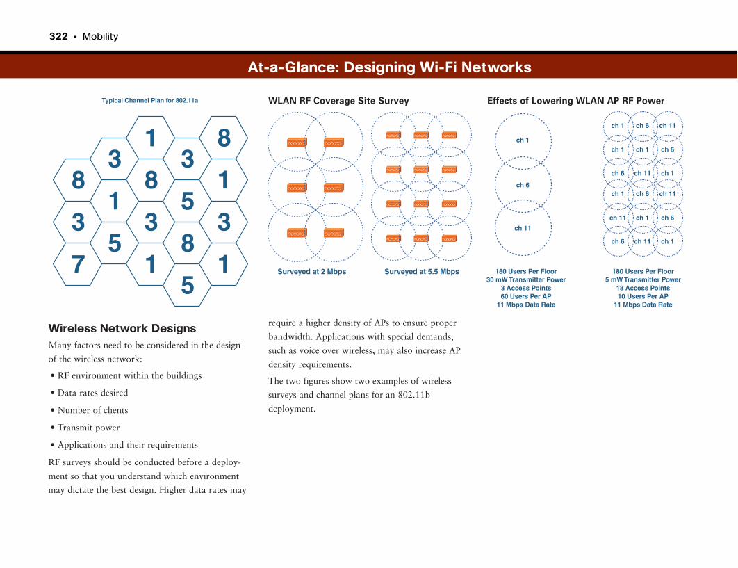
322 • Mobility
Wireless Network DesignsMany factors need to be considered in the design
of the wireless network:
• RF environment within the buildings
• Data rates desired
• Number of clients
• Transmit power
• Applications and their requirements
RF surveys should be conducted before a deploy-
ment so that you understand which environment
may dictate the best design. Higher data rates may
At-a-Glance: Designing Wi-Fi Networks
Typical Channel Plan for 802.11a
31 8
38
18 1
53
53 3
87 1 1
5Surveyed at 2 Mbps Surveyed at 5.5 Mbps 180 Users Per Floor
30 mW Transmitter Power3 Access Points60 Users Per AP
11 Mbps Data Rate
ch 11
ch 6
ch 1
180 Users Per Floor5 mW Transmitter Power
18 Access Points10 Users Per AP
11 Mbps Data Rate
ch 6
ch 11
ch 1
ch 6
ch 1
ch 1
ch 11
ch 1
ch 6
ch 11
ch 1
ch 6
ch 1
ch 6
ch 11
ch 1
ch 6
ch 11
require a higher density of APs to ensure proper
bandwidth. Applications with special demands,
such as voice over wireless, may also increase AP
density requirements.
The two figures show two examples of wireless
surveys and channel plans for an 802.11b
deployment.
WLAN RF Coverage Site Survey Effects of Lowering WLAN AP RF Power
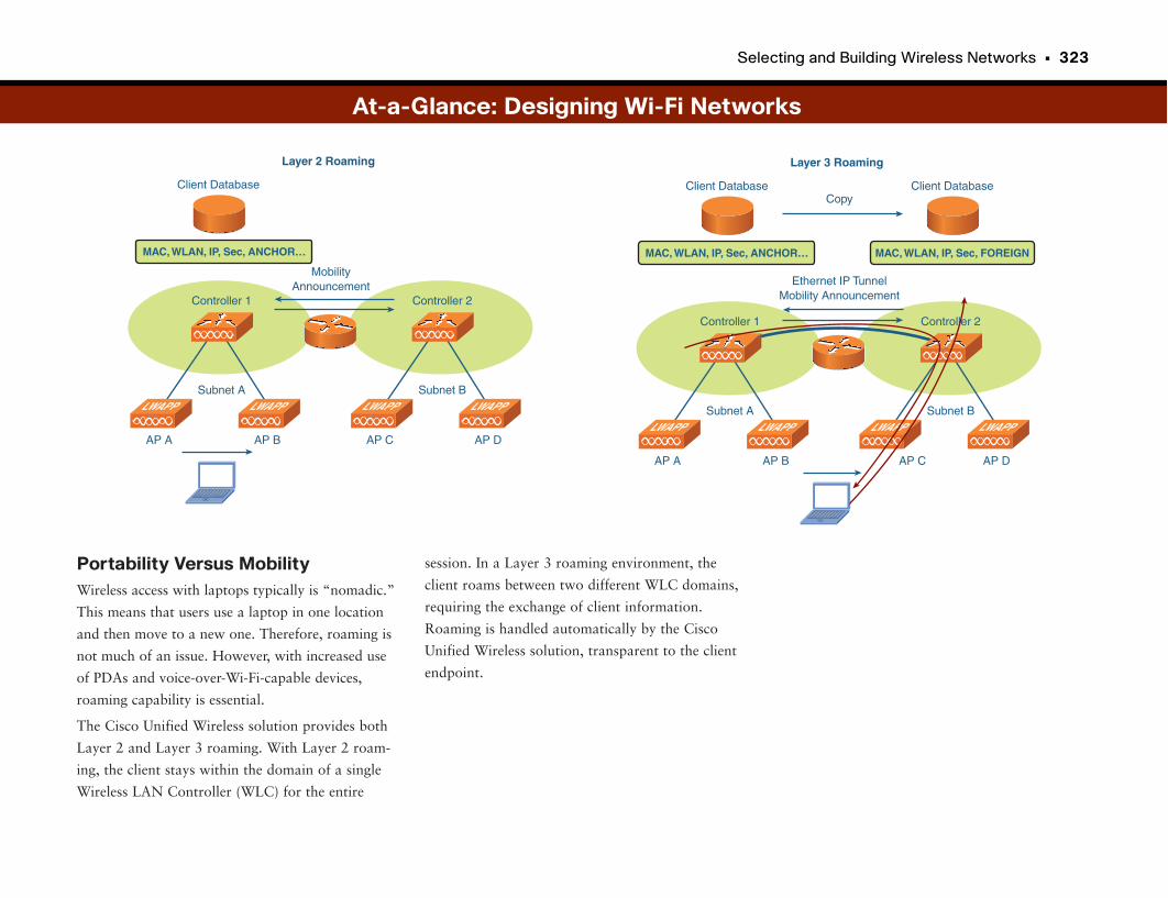
Selecting and Building Wireless Networks • 323
Portability Versus MobilityWireless access with laptops typically is “nomadic.”
This means that users use a laptop in one location
and then move to a new one. Therefore, roaming is
not much of an issue. However, with increased use
of PDAs and voice-over-Wi-Fi-capable devices,
roaming capability is essential.
The Cisco Unified Wireless solution provides both
Layer 2 and Layer 3 roaming. With Layer 2 roam-
ing, the client stays within the domain of a single
Wireless LAN Controller (WLC) for the entire
session. In a Layer 3 roaming environment, the
client roams between two different WLC domains,
requiring the exchange of client information.
Roaming is handled automatically by the Cisco
Unified Wireless solution, transparent to the client
endpoint.
Layer 3 Roaming
AP A AP B
MAC, WLAN, IP, Sec, ANCHOR…
LWAPP LWAPP
Controller 1
Subnet A
AP C AP D
LWAPP LWAPP
Controller 2
Subnet B
Ethernet IP TunnelMobility Announcement
Client Database
MAC, WLAN, IP, Sec, FOREIGN
Client DatabaseCopy
At-a-Glance: Designing Wi-Fi Networks
Layer 2 Roaming
AP A AP B
MAC, WLAN, IP, Sec, ANCHOR…
LWAPP LWAPP
Controller 1
Subnet A
AP C AP D
LWAPP LWAPP
Controller 2
Subnet B
MobilityAnnouncement
Client Database
Securing Wireless Networks
Locking Down WirelessFor every networking innovation, there is a hacker looking to exploit it. The
advent of wireless networking was no different; in fact, the hackers had a field
day with this one early on. The reason is that before wireless, hackers had
only two ways to get into a network: They could either penetrate it from the
Internet or could get physical access to a live switch port inside the network.
Despite all the news about hacking, breaching a corporate network from the
Internet is extremely difficult. This method provides a lot of anonymity
(always a plus when breaking the law). If someone can get access to the switch
port, the technical stuff is easy. There is, of course, the matter of being caught
and detained, though.
When wireless came about, it was a dream for hackers, because they could sit
in a car in the parking lot, or even on a bench outside, protecting their
anonymity while taking advantage of what was a live port on the network.
You may be wondering why those clever IT guys didn’t see this coming. The
truth is, they did. In fact, wireless was viewed as such a problem that many
companies refused to implement it because of the security risks. However,
wireless became accessible and affordable on the consumer side. Corporate
employees instantly understood the productivity gains of being able to remain
connected while away from their desks. As soon as the prices of wireless
routers began to drop, they did what made sense to them. They plugged their
own wireless access points—literally, their own personal hotspots—into the
ports in their offices so that they could roam around and check e-mail.
Now IT had a huge problem. Not only was wireless a known security risk, but
they had open wireless APs that they did not control all over their networks.
This was the birth of the “rogue” AP, and it made their security look like
Swiss cheese. This is when something really interesting happened. IT realized
that the wireless cat could not be stuffed back in the bag. Wireless was here to
stay. The people had mandated that they have wireless access, and IT depart-
ments realized it was better to “own” wireless so that they could properly
secure it.
Balancing Security and AccessMost people in networking believe that balancing security and access is a zero-
sum game: give to one, and you must take from the other. Wireless security
was no different in the beginning, because users were forced to enter 26-digit
hexadecimal codes to gain secure wireless access. It was a pain, but that was
the price you paid for checking your e-mail when meetings started to get
boring.
Wireless security has come a long way from the “easily” breached Wired
Equivalent Privacy (WEP) security keys to the more secure Wi-Fi Protected
Access (WPA) and WPA2 security standards. Ease of use has also been
improved. Laptops are usually preconfigured by IT so that users can securely
connect without a lot of additional steps.
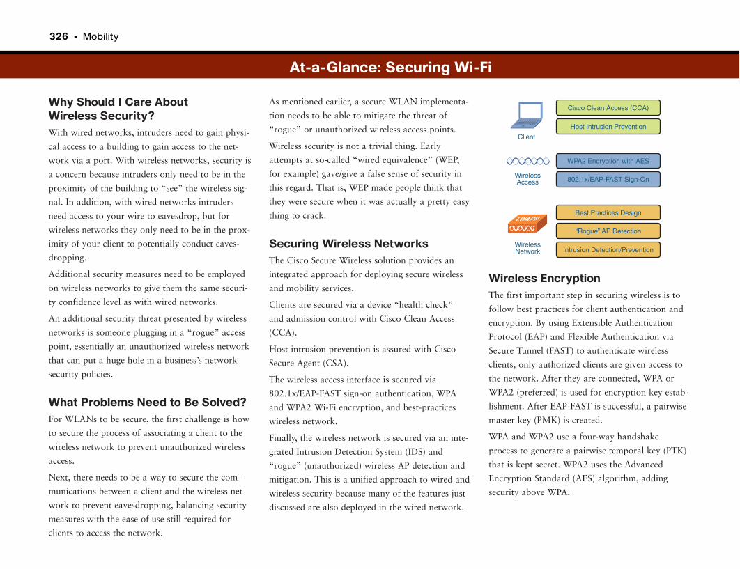
326 • Mobility
Why Should I Care About Wireless Security?With wired networks, intruders need to gain physi-
cal access to a building to gain access to the net-
work via a port. With wireless networks, security is
a concern because intruders only need to be in the
proximity of the building to “see” the wireless sig-
nal. In addition, with wired networks intruders
need access to your wire to eavesdrop, but for
wireless networks they only need to be in the prox-
imity of your client to potentially conduct eaves-
dropping.
Additional security measures need to be employed
on wireless networks to give them the same securi-
ty confidence level as with wired networks.
An additional security threat presented by wireless
networks is someone plugging in a “rogue” access
point, essentially an unauthorized wireless network
that can put a huge hole in a business’s network
security policies.
What Problems Need to Be Solved?For WLANs to be secure, the first challenge is how
to secure the process of associating a client to the
wireless network to prevent unauthorized wireless
access.
Next, there needs to be a way to secure the com-
munications between a client and the wireless net-
work to prevent eavesdropping, balancing security
measures with the ease of use still required for
clients to access the network.
Wireless EncryptionThe first important step in securing wireless is to
follow best practices for client authentication and
encryption. By using Extensible Authentication
Protocol (EAP) and Flexible Authentication via
Secure Tunnel (FAST) to authenticate wireless
clients, only authorized clients are given access to
the network. After they are connected, WPA or
WPA2 (preferred) is used for encryption key estab-
lishment. After EAP-FAST is successful, a pairwise
master key (PMK) is created.
WPA and WPA2 use a four-way handshake
process to generate a pairwise temporal key (PTK)
that is kept secret. WPA2 uses the Advanced
Encryption Standard (AES) algorithm, adding
security above WPA.
As mentioned earlier, a secure WLAN implementa-
tion needs to be able to mitigate the threat of
“rogue” or unauthorized wireless access points.
Wireless security is not a trivial thing. Early
attempts at so-called “wired equivalence” (WEP,
for example) gave/give a false sense of security in
this regard. That is, WEP made people think that
they were secure when it was actually a pretty easy
thing to crack.
Securing Wireless NetworksThe Cisco Secure Wireless solution provides an
integrated approach for deploying secure wireless
and mobility services.
Clients are secured via a device “health check”
and admission control with Cisco Clean Access
(CCA).
Host intrusion prevention is assured with Cisco
Secure Agent (CSA).
The wireless access interface is secured via
802.1x/EAP-FAST sign-on authentication, WPA
and WPA2 Wi-Fi encryption, and best-practices
wireless network.
Finally, the wireless network is secured via an inte-
grated Intrusion Detection System (IDS) and
“rogue” (unauthorized) wireless AP detection and
mitigation. This is a unified approach to wired and
wireless security because many of the features just
discussed are also deployed in the wired network.
At-a-Glance: Securing Wi-Fi
Cisco Clean Access (CCA)
Intrusion Detection/Prevention
“Rogue” AP Detection
Best Practices Design
802.1x/EAP-FAST Sign-On
WPA2 Encryption with AES
Host Intrusion Prevention
WirelessAccess
WirelessNetwork
LWAPP
Client
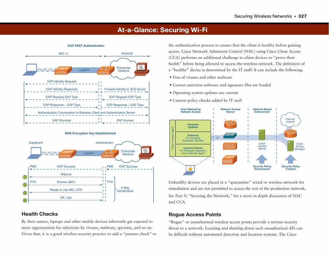
Securing Wireless Networks • 327
Health ChecksBy their nature, laptops and other mobile devices inherently get exposed to
more opportunities for infections by viruses, malware, spyware, and so on.
Given that, it is a good wireless security practice to add a “posture check” to
the authentication process to ensure that the client is healthy before gaining
access. Cisco Network Admission Control (NAC) using Cisco Clean Access
(CCA) performs an additional challenge to client devices to “prove their
health” before being allowed to access the wireless network. The definition of
a “healthy” device is determined by the IT staff. It can include the following:
• Free of viruses and other malware
• Correct antivirus software and signature files are loaded
• Operating system updates are current
• Custom policy checks added by IT staff
Unhealthy devices are placed in a “quarantine” wired or wireless network for
remediation and are not permitted to access the rest of the production network.
See Part V, “Securing the Network,” for a more in-depth discussion of NAC
and CCA.
Rogue Access Points“Rogue” or unauthorized wireless access points provide a serious security
threat to a network. Locating and shutting down such unauthorized APs can
be difficult without automated detection and location systems. The Cisco
At-a-Glance: Securing Wi-Fi
IP
Host AttemptingNetwork Access
Network AccessDevice
Network-BasedEnforcement
Security PolicyEnforcement
Internet/Intranet
LWAPP
Security PolicyCreation
CleanAccessServer
CleanAccess
Manager
WindowsUpdates
AntivirusFor Example,
Symantec, McAfee
Custom ChecksFor Example, Spyware,Cisco Security Agent
Cle
an A
cces
s A
gent
LWAPP
802.1x
LWAPP
EAP-FAST Authentication
EnterpriseNetwork
EAP-Identity-Request
EAP-Identity-Response
EAP-Request EAP Type
EAP-Response – EAP Type
EAP-Success
Forward Identity to ACS Server
EAP-Request EAP Type
EAP-Response – EAP Type
EAP-Sucess
RADIUS
Authentication Conversation Is Between Client and Authentication Server
LWAPP LWAPP
Supplicant Authenticator
WPA Encryption Key Establishment
EnterpriseNetwork
EAP-Success
ANonce
Snonce (MIC)
Ready to Use MIC, GTK4-Way
Handshakes
OK, Use
PMK
PTK PTK
EAP SuccessPMK
1
2
3
4
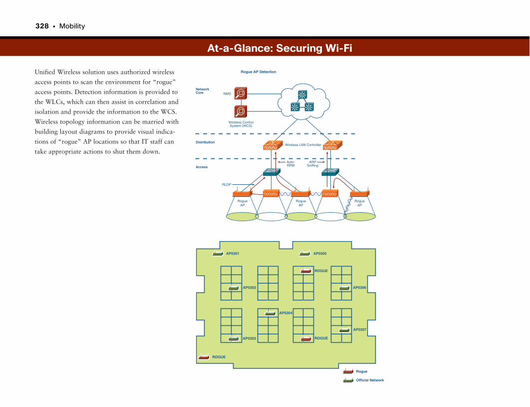
328 • Mobility
Unified Wireless solution uses authorized wireless
access points to scan the environment for “rogue”
access points. Detection information is provided to
the WLCs, which can then assist in correlation and
isolation and provide the information to the WCS.
Wireless topology information can be married with
building layout diagrams to provide visual indica-
tions of “rogue” AP locations so that IT staff can
take appropriate actions to shut them down.
At-a-Glance: Securing Wi-Fi
Rogue
ROGUE
ROGUE
ROGUE
Official Network
AP0301 AP0305
AP0307
AP0302 AP0306
AP0304
AP0303
RogueAP
Wireless ControlSystem (WCS)
NMS
Rogue AP Detection
NetworkCore
Distribution
Access
Wireless LAN Controller
RLDP
Auto-RRM
Si
Si Si
ARPSniffing
RogueAP
RogueAP

This page intentionally left blank
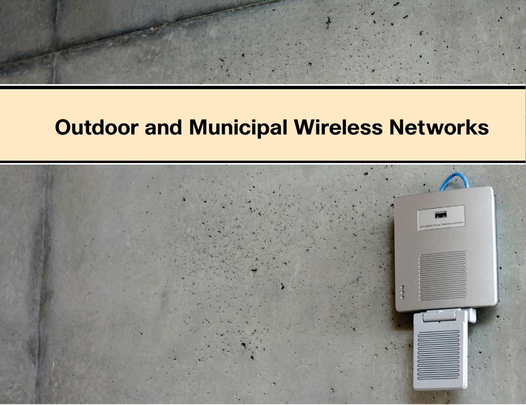
Outdoor and Municipal Wireless Networks
It’s Just Like a Building, Only Way BiggerMaybe we’re all just being greedy. Fifteen years ago most people didn’t even
have an e-mail account. Few had ever connected to the Internet. Five years ago
everyone you know probably had an e-mail account; in some cases it was the
only way you communicated with them. Then came wireless networking,
because those e-mails couldn’t wait until the end of the meeting, so we had
wireless throughout our workplace and home.
Now, not even this is good enough. We want to connect at the park, or while
waiting in line at the DMV, or while on a city bus, or while camped out on a
curb waiting for a parade to start. In other words, we want to be connected
now, now, now, and everywhere. So much for work-life balance.
All kidding aside, the need for connectivity is seemingly insatiable. Many
towns and cities are catching on and are looking to install citywide (also called
municipal or muni) wireless for a number of reasons. One of the primary rea-
sons is that just as it does for corporate workers in an office, wireless connec-
tivity can increase the productivity of city workers and officials. In addition,
the availability of muni wireless makes for a happy populace, especially when
it is offered for free.
Of course, citywide wireless access involves some unique considerations. There
is the obvious issue with scale, but designers must also deal with the elements,
because access points are likely to be outside.
There is also the issue of connecting the access points back to the physical net-
work, because cities don’t come with handy drop ceilings to run cables
through. As with any wireless system, security is also a concern, especially
when secure channels (such as police traffic) must be maintained on the same
network used for public access.
One major issue with muni Wi-Fi is funding and return on investment (ROI).
Some free and even subscription muni Wi-Fi systems have failed because of a
nonsustainable business model to fund and maintain the systems. It’s also
worth noting, though, that some cities fund these systems through public
works (tax-supported) projects.
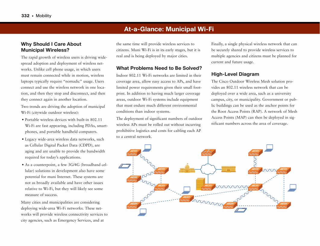
332 • Mobility
Why Should I Care About Municipal Wireless?The rapid growth of wireless users is driving wide-
spread adoption and deployment of wireless net-
works. Unlike cell phone usage, in which users
must remain connected while in motion, wireless
laptops typically require “nomadic” usage. Users
connect and use the wireless network in one loca-
tion, and then they stop and disconnect, and then
they connect again in another location.
Two trends are driving the adoption of municipal
Wi-Fi (citywide outdoor wireless):
• Portable wireless devices with built-in 802.11
Wi-Fi are fast appearing, including PDAs, smart-
phones, and portable handheld computers.
• Legacy wide-area wireless data networks, such
as Cellular Digital Packet Data (CDPD), are
aging and are unable to provide the bandwidth
required for today’s applications.
• As a counterpoint, a few 3G/4G (broadband cel-
lular) solutions in development also have some
potential for muni Internet. These systems are
not as broadly available and have other issues
relative to Wi-Fi, but they will likely see some
measure of success.
Many cities and municipalities are considering
deploying wide-area Wi-Fi networks. These net-
works will provide wireless connectivity services to
city agencies, such as Emergency Services, and at
Finally, a single physical wireless network that can
be securely shared to provide wireless services to
multiple agencies and citizens must be planned for
current and future usage.
High-Level DiagramThe Cisco Outdoor Wireless Mesh solution pro-
vides an 802.11 wireless network that can be
deployed over a wide area, such as a university
campus, city, or municipality. Government or pub-
lic buildings can be used as the anchor points for
the Root Access Points (RAP). A network of Mesh
Access Points (MAP) can then be deployed in sig-
nificant numbers across the area of coverage.
the same time will provide wireless services to
citizens. Muni Wi-Fi is in its early stages, but it is
real and is being deployed by major cities.
What Problems Need to Be Solved?Indoor 802.11 Wi-Fi networks are limited in their
coverage area, allow easy access to APs, and have
limited power requirements given their small foot-
print. In addition to having much larger coverage
areas, outdoor Wi-Fi systems include equipment
that must endure much different environmental
conditions than indoor systems.
The deployment of significant numbers of outdoor
wireless APs must be rolled out without incurring
prohibitive logistics and costs for cabling each AP
to a central network.
At-a-Glance: Municipal Wi-Fi
UNIVERSITYUNIVERSITY
MESHMESH
MESH
MESH
MESH MESH
MESH MESH
MESH
MESH
MESH
MESH MESH
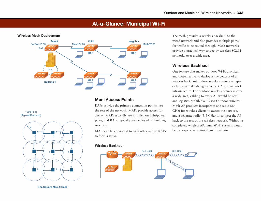
Outdoor and Municipal Wireless Networks • 333
The mesh provides a wireless backhaul to the
wired network and also provides multiple paths
for traffic to be routed through. Mesh networks
provide a practical way to deploy wireless 802.11
networks over a wide area.
Wireless BackhaulOne feature that makes outdoor Wi-Fi practical
and cost-effective to deploy is the concept of a
wireless backhaul. Indoor wireless networks typi-
cally use wired cabling to connect APs to network
infrastructure. For outdoor wireless networks over
a wide area, cabling to every AP would be cost-
and logistics-prohibitive. Cisco Outdoor Wireless
Mesh AP products incorporate one radio (2.4
GHz) for wireless clients to access the network,
and a separate radio (5.8 GHz) to connect the AP
back to the rest of the wireless network. Without a
completely wireless AP, muni Wi-Fi systems would
be too expensive to install and maintain.
Muni Access PointsRAPs provide the primary connection points into
the rest of the network. MAPs provide access for
clients. MAPs typically are installed on light/power
poles, and RAPs typically are deployed on building
rooftops.
MAPs can be connected to each other and to RAPs
to form a mesh.
At-a-Glance: Municipal Wi-Fi
One Square Mile, 9 Cells
1000 Feet(Typical Distance)
(5.8 Ghz) (2.4 Ghz)MESHMESH
Wireless Backhaul
Wireless Mesh Deployment
Rooftop:d6:80 Mesh:7a:70 Mesh:78:90
RAP
Building 1MAP
Parent NeighborChild
LAN
MESH MESH MESH
MAP
MESH
MAP
MESH
MAP
MESHMESH
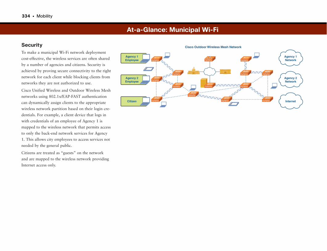
334 • Mobility
SecurityTo make a municipal Wi-Fi network deployment
cost-effective, the wireless services are often shared
by a number of agencies and citizens. Security is
achieved by proving secure connectivity to the right
network for each client while blocking clients from
networks they are not authorized to use.
Cisco Unified Wireless and Outdoor Wireless Mesh
networks using 802.1x/EAP-FAST authentication
can dynamically assign clients to the appropriate
wireless network partition based on their login cre-
dentials. For example, a client device that logs in
with credentials of an employee of Agency 1 is
mapped to the wireless network that permits access
to only the back-end network services for Agency
1. This allows city employees to access services not
needed by the general public.
Citizens are treated as “guests” on the network
and are mapped to the wireless network providing
Internet access only.
At-a-Glance: Municipal Wi-Fi
Cisco Outdoor Wireless Mesh Network
UNIVERSITYUNIVERSITY
MESHMESH
MESH
MESH
MESH MESH
MESH MESH
MESH
MESH
MESH
MESH MESH
Agency 1Employee
Agency 2Employee
Citizen
Agency 1Network
Agency 2Network
Internet

This page intentionally left blank

VoIP over Wireless Networks
Wireless VoIPFor more than 100 years, phones were attached to a wall and connected to a
switched network using copper wires. Then, in seemingly rapid-fire succession,
the system went digital. Then cordless technology let us break away from the
wall. Then cellular technology let us break away from homes. Then the phone
system was ported to the data IP network. And now we want to move around
the office with our phone the same way we do with our laptop. And we don’t
just want to move around with our cell phone. We want to move around with
our desk phone—the one associates and customers call us on. We wanted it,
and we got it. Man, are we spoiled!
Wireless VoIP might seem like a natural extension of VoIP technology, because
the wireless system is already in place, right? Well, not quite. Moving VoIP to
the wireless network actually presents some huge challenges for IT staffs. First
is the issue of the phones moving around. Unlike network access for a laptop,
there are issues with call processing, voice quality, and bandwidth require-
ments. (Nothing can wreck an IT guy’s day like a conference room full of peo-
ple reaching for their VoIP phones on break.)
Another big issue for wireless VoIP is that people use phones in places where
they would not use their laptop. It sounds strange, but when the IT folks were
installing the WLAN, they probably didn’t worry about having coverage in
stairwells because nobody would stop there, open his laptop, and check his e-
mail. He would, however, want to make, take, or continue a call while walk-
ing up the stairs.
Finally, there is the issue of mobility. Unlike wireless laptop users, wireless
VoIP users expect to use the system while moving. This requires a lot of power
and puts a big strain on the battery life of VoIP devices, among other issues.
This also has some serious design implications well beyond those for data-only
wireless networks.
Although this may seem like a bunch of big problems, they are worth over-
coming because of the productivity gains that wireless yields. Besides, the IT
guys don’t have much on their plates. Just connect the phone to the wireless
thingy.
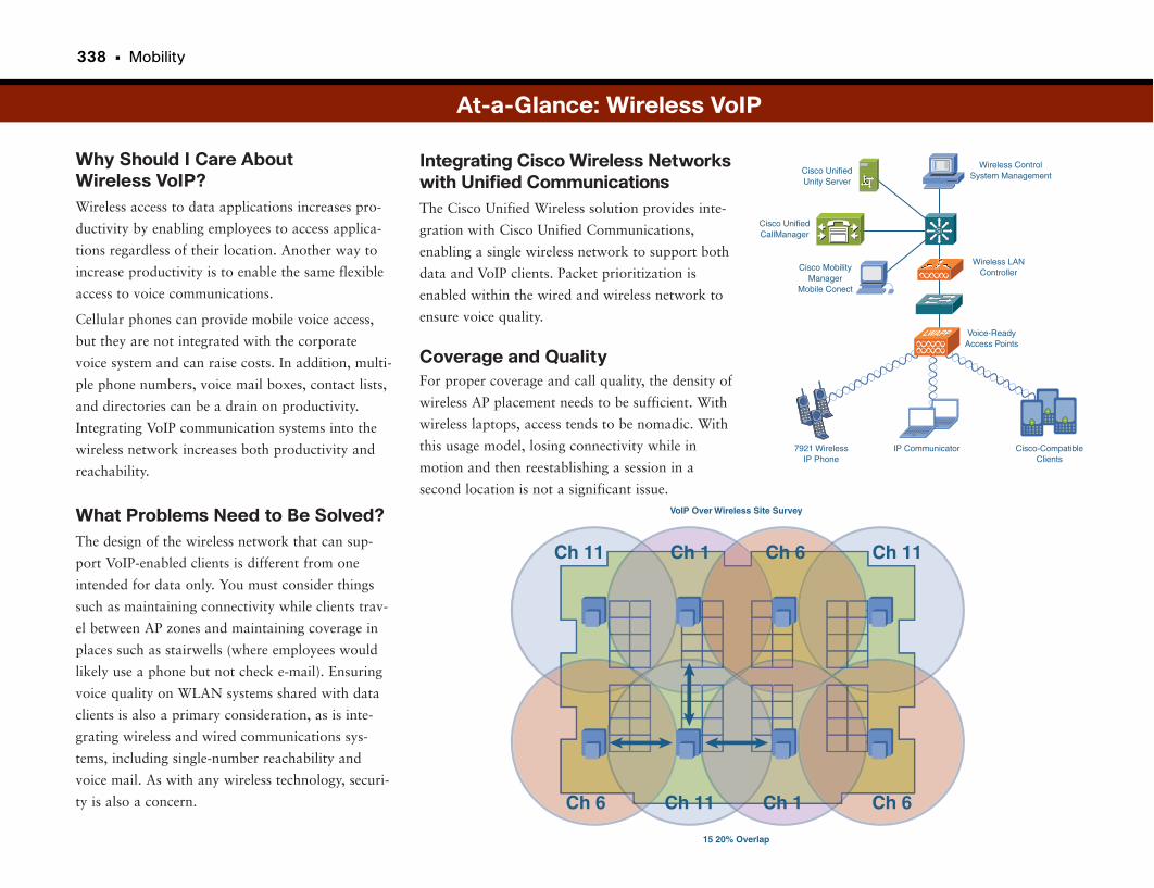
338 • Mobility
Why Should I Care About Wireless VoIP?Wireless access to data applications increases pro-
ductivity by enabling employees to access applica-
tions regardless of their location. Another way to
increase productivity is to enable the same flexible
access to voice communications.
Cellular phones can provide mobile voice access,
but they are not integrated with the corporate
voice system and can raise costs. In addition, multi-
ple phone numbers, voice mail boxes, contact lists,
and directories can be a drain on productivity.
Integrating VoIP communication systems into the
wireless network increases both productivity and
reachability.
What Problems Need to Be Solved?The design of the wireless network that can sup-
port VoIP-enabled clients is different from one
intended for data only. You must consider things
such as maintaining connectivity while clients trav-
el between AP zones and maintaining coverage in
places such as stairwells (where employees would
likely use a phone but not check e-mail). Ensuring
voice quality on WLAN systems shared with data
clients is also a primary consideration, as is inte-
grating wireless and wired communications sys-
tems, including single-number reachability and
voice mail. As with any wireless technology, securi-
ty is also a concern.
Integrating Cisco Wireless Networkswith Unified CommunicationsThe Cisco Unified Wireless solution provides inte-
gration with Cisco Unified Communications,
enabling a single wireless network to support both
data and VoIP clients. Packet prioritization is
enabled within the wired and wireless network to
ensure voice quality.
Coverage and QualityFor proper coverage and call quality, the density of
wireless AP placement needs to be sufficient. With
wireless laptops, access tends to be nomadic. With
this usage model, losing connectivity while in
motion and then reestablishing a session in a
second location is not a significant issue.
At-a-Glance: Wireless VoIP
15 20% Overlap
VoIP Over Wireless Site Survey
Ch 11 Ch 1 Ch 6
Ch 11Ch 6 Ch 6Ch 1
Ch 11
Wireless ControlSystem Management
Cisco UnifiedUnity Server
Cisco MobilityManager
Mobile Conect
Cisco UnifiedCallManager
Voice-ReadyAccess Points
Wireless LANController
7921 WirelessIP Phone
IP Communicator Cisco-CompatibleClients
Si
LWAPP
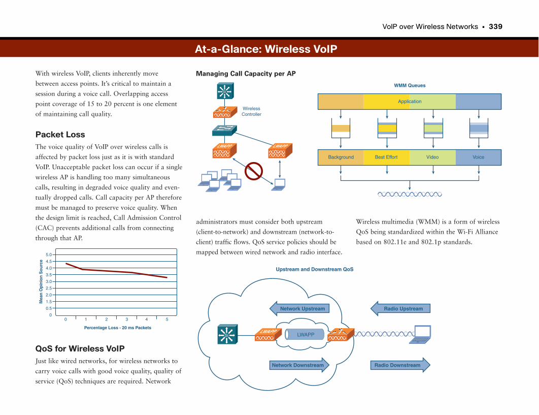
VoIP over Wireless Networks • 339
With wireless VoIP, clients inherently move
between access points. It’s critical to maintain a
session during a voice call. Overlapping access
point coverage of 15 to 20 percent is one element
of maintaining call quality.
Packet LossThe voice quality of VoIP over wireless calls is
affected by packet loss just as it is with standard
VoIP. Unacceptable packet loss can occur if a single
wireless AP is handling too many simultaneous
calls, resulting in degraded voice quality and even-
tually dropped calls. Call capacity per AP therefore
must be managed to preserve voice quality. When
the design limit is reached, Call Admission Control
(CAC) prevents additional calls from connecting
through that AP.
QoS for Wireless VoIPJust like wired networks, for wireless networks to
carry voice calls with good voice quality, quality of
service (QoS) techniques are required. Network
At-a-Glance: Wireless VoIP
Percentage Loss - 20 ms Packets
Mea
n O
pin
ion
So
urc
e
00
0.5
1 2 3 4 5
1.5
2.0
2.5
3.0
3.5
4.0
4.5
5.0
LWAPPSi
Network Upstream
Upstream and Downstream QoS
Radio Upstream
Network Downstream Radio Downstream
LWAPP
Managing Call Capacity per AP
Wireless multimedia (WMM) is a form of wireless
QoS being standardized within the Wi-Fi Alliance
based on 802.11e and 802.1p standards.
administrators must consider both upstream
(client-to-network) and downstream (network-to-
client) traffic flows. QoS service policies should be
mapped between wired network and radio interface.
WirelessController
Si
LWAPP LWAPP
WMM Queues
Application
Background Best Effort Video Voice
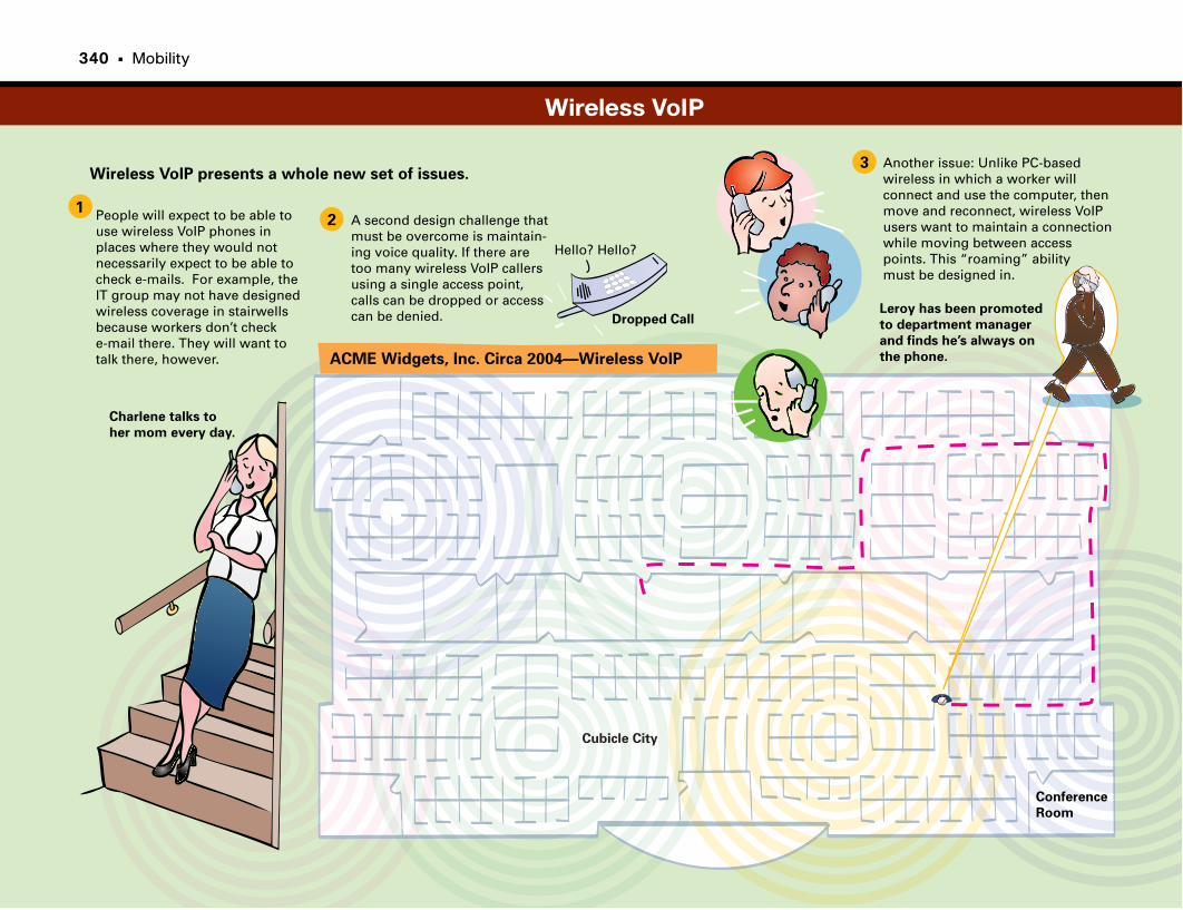
Another issue: Unlike PC-based wireless in which a worker will connect and use the computer, thenmove and reconnect, wireless VoIP users want to maintain a connectionwhile moving between access points. This “roaming” ability must be designed in.
Conference
Room
Cubicle City
ACME Widgets, Inc. Circa 2004—Wireless VoIP
12
3Wireless VoIP presents a whole new set of issues.
People will expect to be able to use wireless VoIP phones inplaces where they would notnecessarily expect to be able to check e-mails. For example, the IT group may not have designedwireless coverage in stairwells because workers don’t check e-mail there. They will want to talk there, however.
Charlene talks to
her mom every day.
A second design challenge that must be overcome is maintain-ing voice quality. If there are too many wireless VoIP callers using a single access point,calls can be dropped or access can be denied.
Hello? Hello?
Dropped CallLeroy has been promoted
to department manager
and finds he’s always on
the phone.
Wireless VoIP
340 • Mobility

This page intentionally left blank
Wireless Guest Access

Mi Casa Es Su CasaIt’s amusing to think how little time it has taken us to go from being excited
that wireless was available in some places to demanding that it be everywhere
in our work environment. Now, even when you visit another company, you
pretty much expect to obtain guest access to that person’s network so that you
can connect back to your office, e-mail, and other communication tools and
information.
Guest access is pretty easy to figure out. The tricky part is making it simple
enough that any visitor can connect without help from your IT staff. Trust
us—the day one of your IT staffers is caught hanging out in the lobby helping
the salesmen who are waiting around to get connected, the deal is off.
Guest access has to be simple and secure. By secure, we don’t mean encrypted.
We mean that guest traffic does not mingle with our traffic, and guests get
punted straight to the Internet. For the most part, the security of their data is
entirely up to them. This group must also be prevented from impacting the
performance or bandwidth of our own corporate users (in other words, “best
effort”).
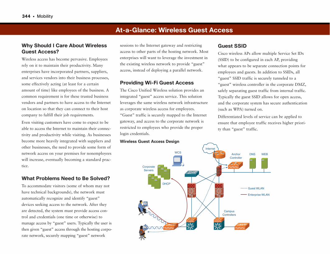
344 • Mobility
Why Should I Care About WirelessGuest Access?Wireless access has become pervasive. Employees
rely on it to maintain their productivity. Many
enterprises have incorporated partners, suppliers,
and services vendors into their business processes,
some effectively acting (at least for a certain
amount of time) like employees of the business. A
common requirement is for these trusted business
vendors and partners to have access to the Internet
on location so that they can connect to their host
company to fulfill their job requirements.
Even visiting customers have come to expect to be
able to access the Internet to maintain their connec-
tivity and productivity while visiting. As businesses
become more heavily integrated with suppliers and
other businesses, the need to provide some form of
network access on your premises for nonemployees
will increase, eventually becoming a standard prac-
tice.
What Problems Need to Be Solved?To accommodate visitors (some of whom may not
have technical backgrounds), the network must
automatically recognize and identify “guest”
devices seeking access to the network. After they
are detected, the system must provide access con-
trol and credentials (one time or otherwise) to
manage access by “guest” users. Typically the user is
then given “guest” access through the hosting corpo-
rate network, securely mapping “guest” network
Guest SSIDCisco wireless APs allow multiple Service Set IDs
(SSID) to be configured in each AP, providing
what appears to be separate connection points for
employees and guests. In addition to SSIDs, all
“guest” SSID traffic is securely tunneled to a
“guest” wireless controller in the corporate DMZ,
safely separating guest traffic from internal traffic.
Typically the guest SSID allows for open access,
and the corporate system has secure authentication
(such as WPA) turned on.
Differentiated levels of service can be applied to
ensure that employee traffic receives higher priori-
ty than “guest” traffic.
sessions to the Internet gateway and restricting
access to other parts of the hosting network. Most
enterprises will want to leverage the investment in
the existing wireless network to provide “guest”
access, instead of deploying a parallel network.
Providing Wi-Fi Guest AccessThe Cisco Unified Wireless solution provides an
integrated “guest” access service. This solution
leverages the same wireless network infrastructure
as corporate wireless access for employees.
“Guest” traffic is securely mapped to the Internet
gateway, and access to the corporate network is
restricted to employees who provide the proper
login credentials.
At-a-Glance: Wireless Guest Access
Internet
DNS
CampusControllers
Guest WLAN
Enterprise WLAN
AnchorController
WEB
CorporateServers
WCS
DHCP
LWAPP LWAPP
Wireless Guest Access Design
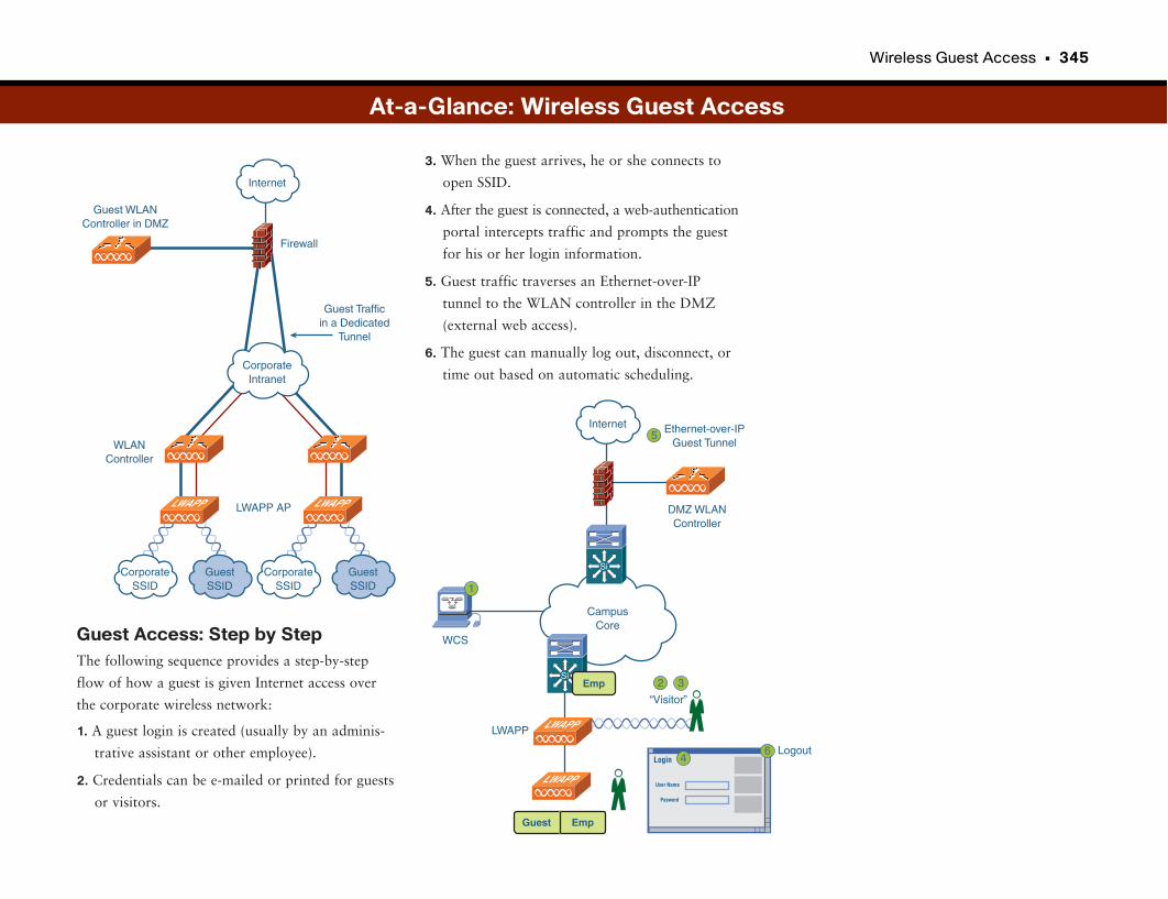
Wireless Guest Access • 345
Guest Access: Step by StepThe following sequence provides a step-by-step
flow of how a guest is given Internet access over
the corporate wireless network:
1. A guest login is created (usually by an adminis-
trative assistant or other employee).
2. Credentials can be e-mailed or printed for guests
or visitors.
3. When the guest arrives, he or she connects to
open SSID.
4. After the guest is connected, a web-authentication
portal intercepts traffic and prompts the guest
for his or her login information.
5. Guest traffic traverses an Ethernet-over-IP
tunnel to the WLAN controller in the DMZ
(external web access).
6. The guest can manually log out, disconnect, or
time out based on automatic scheduling.
At-a-Glance: Wireless Guest Access
Internet
CorporateIntranet
Firewall
Guest WLANController in DMZ
Guest Trafficin a Dedicated
Tunnel
LWAPP AP
WLANController
LWAPP
CorporateSSID
GuestSSID
LWAPP
CorporateSSID
GuestSSID
2
Internet
CampusCore
“Visitor”
Logout
LWAPP
WCS
DMZ WLANController
Ethernet-over-IPGuest Tunnel
LWAPP
LWAPP
Si
Si
Guest Emp
Emp
Login
User Name
Pasword
1
3
4
5
6
RFID and Location-Based Services
Finding Your StuffOne of the biggest problems that large companies face is finding their stuff.
This might sound a little silly at first, but consider how much equipment it
takes to run a hospital, or a manufacturing plant, or an engineering test facili-
ty. Those types of businesses have tens or even hundreds of millions of dollars
of equipment located all over a building or plant or campus, and a lot of it is
portable. Now add to that typical employee churn and people’s tendency to
hoard or hide equipment that they use often.
So what happens when a company needs to locate the “machine that goes
bing!” for a procedure or find a piece of equipment for maintenance, or when
it needs to prevent an expensive piece of equipment from being walked out the
door? Unless the company has some sort of location technology in place, the
unfortunate answer is that it must go looking for the item. This is often time-
consuming, frustrating, and fruitless. The good news is that most companies
already have a technology in place to help them find their stuff. It’s their
WLAN.
Wireless LANS: They’re Not Just for Checking E-Mailon the Toilet Anymore!Okay, that was uncalled for. But the point is, the same technology that allows
you to check your e-mail from anywhere in the building can also help you find
your stuff. With the addition of a Wi-Fi asset tag that can communicate with
the in-building wireless access points, and some software that allows you to
use several Wi-Fi APs to locate the device, you can find any piece of equip-
ment in a matter of seconds. This process is called triangularization, a term
sometimes used interchangeably with triangulation.
A technology called Radio Frequency Identification (RFID) not only allows for
asset tracking but also provides instant inventory capability for thousands of
devices per second. With an RFID solution, a company can instantly process
an entire pallet of goods as it comes through the door, and track the location
of the forklift as it places the goods in the warehouse. RFID is something of an
umbrella technology. It can be used as a standalone deployment or can be inte-
grated with Wi-Fi or other wireless solutions.
348 • Mobility
Why Should I Care About WirelessLocation Services?Wireless network technology has applications out-
side of providing wireless access. One such applica-
tion is location-based services, which is the process
of determining and monitoring the location of
business-owned assets.
Assets can be anything of value to the business in
which knowing the item’s location is important:
• Laptop computers
• Specialized medical equipment in hospitals
• Shipments of products or supplies
• Sensors and alarming
• People (scary but true)
In addition to tracking known assets, location-
based services allow a company to track undesir-
able or unauthorized assets, such as the following:
• “Rogue” wireless access points
• “Rogue” laptops
Location-based services can increase productivity,
lower operational costs, and enhance business
process control, all of which are important to
companies.
Different types of electronic wireless (RFID) tags
exist. They use different radio frequencies, includ-
ing LF, HF, and UHF tags for short distances (less
than 6 feet), Wi-Fi clients and tags for distances up
to 300 feet, and cellular telemetry for distances up
to 20 miles. Many different combinations of read-
ers, tags, and technologies exist, each of which
works better in some deployments and worse in
others. Up-front planning is critical to ensure that
readers can identify asset locations with the
desired accuracy.
At-a-Glance: Location-Based Services
Reader 2
Reader 3
Reader 1
Reader 4
Locatable Device 2ID loc. Dev. 1 ID loc. Dev. 2
Locatable Device 1
What Problems Need to Be Solved?Location-based services require two basic
components:
• Locatable devices: Whatever is to be tracked
must have an electronic wireless asset tag or
wireless client.
• Readers: A sensor (or several sensors) must pick
up the signal of locatable devices and provide
information on them.
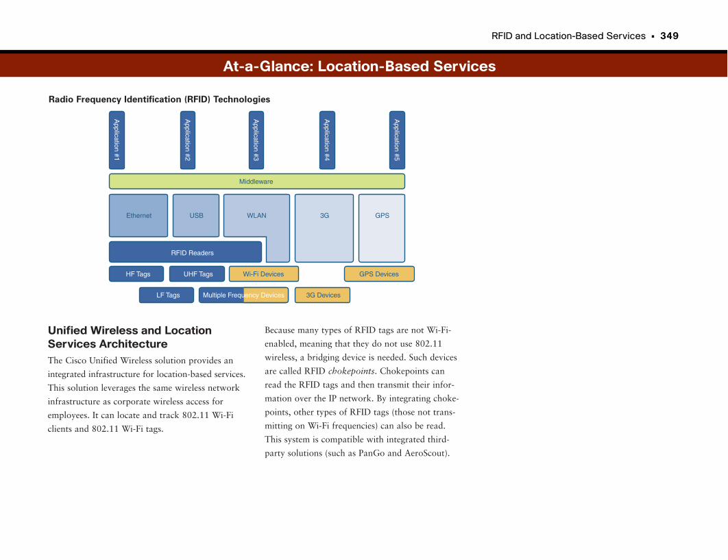
RFID and Location-Based Services • 349
Unified Wireless and LocationServices ArchitectureThe Cisco Unified Wireless solution provides an
integrated infrastructure for location-based services.
This solution leverages the same wireless network
infrastructure as corporate wireless access for
employees. It can locate and track 802.11 Wi-Fi
clients and 802.11 Wi-Fi tags.
Because many types of RFID tags are not Wi-Fi-
enabled, meaning that they do not use 802.11
wireless, a bridging device is needed. Such devices
are called RFID chokepoints. Chokepoints can
read the RFID tags and then transmit their infor-
mation over the IP network. By integrating choke-
points, other types of RFID tags (those not trans-
mitting on Wi-Fi frequencies) can also be read.
This system is compatible with integrated third-
party solutions (such as PanGo and AeroScout).
At-a-Glance: Location-Based Services
Application #1
Application #5
Application #3
Application #2
Application #4
Middleware
Ethernet USB 3G GPSWLAN
RFID Readers
HF Tags UHF Tags Wi-Fi Devices GPS Devices
LF Tags 3G DevicesMultiple Frequency Devices
Radio Frequency Identification (RFID) Technologies
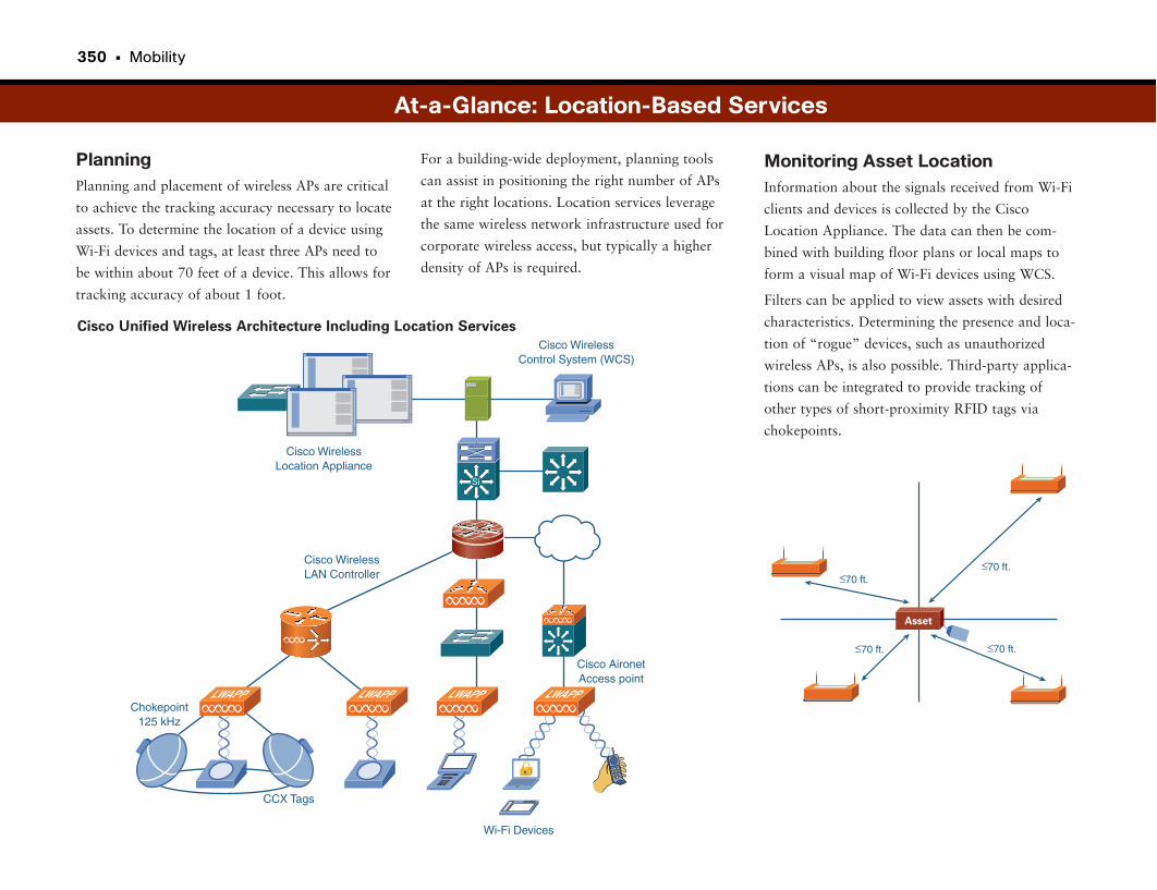
350 • Mobility
PlanningPlanning and placement of wireless APs are critical
to achieve the tracking accuracy necessary to locate
assets. To determine the location of a device using
Wi-Fi devices and tags, at least three APs need to
be within about 70 feet of a device. This allows for
tracking accuracy of about 1 foot.
For a building-wide deployment, planning tools
can assist in positioning the right number of APs
at the right locations. Location services leverage
the same wireless network infrastructure used for
corporate wireless access, but typically a higher
density of APs is required.
At-a-Glance: Location-Based Services
≤70 ft.≤70 ft.
≤70 ft. ≤70 ft.
Asset
Monitoring Asset LocationInformation about the signals received from Wi-Fi
clients and devices is collected by the Cisco
Location Appliance. The data can then be com-
bined with building floor plans or local maps to
form a visual map of Wi-Fi devices using WCS.
Filters can be applied to view assets with desired
characteristics. Determining the presence and loca-
tion of “rogue” devices, such as unauthorized
wireless APs, is also possible. Third-party applica-
tions can be integrated to provide tracking of
other types of short-proximity RFID tags via
chokepoints.Cisco Wireless
Location Appliance
Cisco WirelessLAN Controller
Cisco AironetAccess point
Chokepoint125 kHz
CCX Tags
Wi-Fi Devices
Cisco WirelessControl System (WCS)
LWAPPLWAPPLWAPPLWAPP
Si
Cisco Unified Wireless Architecture Including Location Services
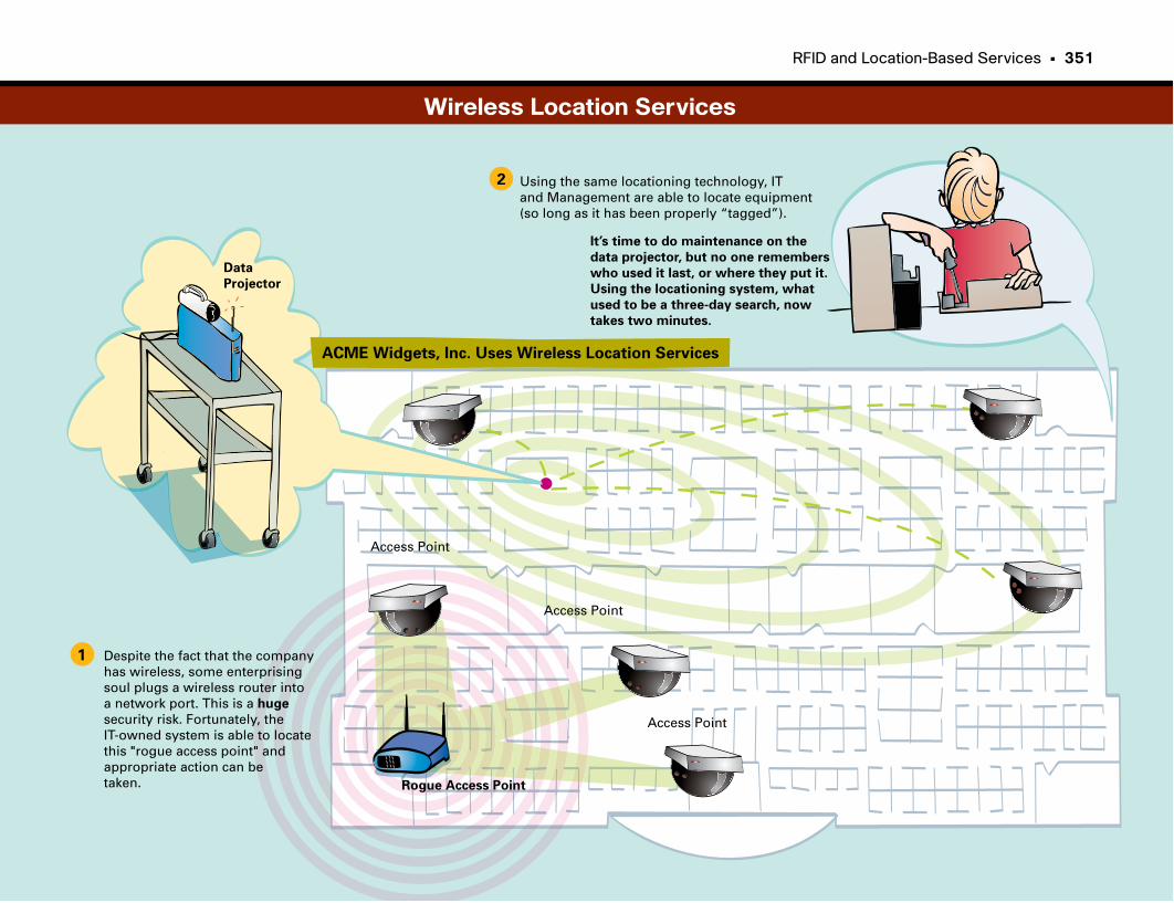
RFID and Location-Based Services • 351
ACME Widgets, Inc. Uses Wireless Location Services
1
2
Despite the fact that the companyhas wireless, some enterprisingsoul plugs a wireless router intoa network port. This is a huge
security risk. Fortunately, the IT-owned system is able to locate this "rogue access point" andappropriate action can betaken.
Access Point
Access Point
Access Point
Rogue Access Point
Data
Projector
Using the same locationing technology, IT and Management are able to locate equipment(so long as it has been properly “tagged”).
It’s time to do maintenance on the
data projector, but no one remembers
who used it last, or where they put it.
Using the locationing system, what
used to be a three-day search, now
takes two minutes.
Wireless Location Services
Part IX
Virtualized NetworksNow that you know how everything in a network goes together, it’s time to break it all apart again. It sounds a bit crazy,
but the truth is that little is simple about today’s networks. They are complex, and they are a big investment. New resources
are added or required on almost a weekly or even daily basis. To better handle this never-ending stream of network addi-
tions, many IT groups have begun to virtualize parts of the network, including data centers, infrastructure, and even appli-
cations. The idea behind virtualization is to pool network resources to reduce costs, size, and expense while making it
appear as if all these services are standalone and purpose-built.
Think about virtualization as being like living in an apartment with three roommates. The four of you could each rent a separate
apartment, pay your own rent, pay for your own utilities, have to furnish your unit, and have to clean it or hire a cleaning service.
This is nice if you can afford it, but what if you can’t? Chances are you may be sleeping on an air mattress, building shelves with
cinder blocks and milk crates, eating mac-n-cheese a lot, and probably skimping where you can on utilities. The advantage is that
it’s extremely private, and you can do whatever you want to in your unit. You can be a slob if you choose.
Another option is for the four of you to share an apartment. You split the rent and utilities, you each provide part of the fur-
nishings, and you all chip in for a single cleaning service. Overall, your apartment furnishings and quality of living probably
will improve. Privacy may be an issue. There would have to be some level of coordination between roommates about what
resources and spaces are to be shared and which ones are personal and private. You probably also would need some agree-
ments about what is acceptable and what is not. For example, hanging your socks to dry in the living room probably is out.
Virtualization of networks is very similar. Each department or work group could set up its own network, its own voice servic-
es, its own file servers, and its own WAN to connect to members of the department at another location. Doing so would be
fairly cost- and resource-prohibitive. A better option is to share the same network and resources such as file servers. Each work
group unit would have access to a set of shared resources and some allocation of private resources, splitting the overall IT
costs with other work groups.
This section starts by looking at virtualizing data centers and network storage. Here users get access to file storage or applications
that appear to be purpose-built (standalone) data centers or servers but that are actually single data centers with logical partitions.
Next we look at virtualizing the network itself. This is important when a company wants to leverage its investment in a sin-
gle physical network but wants to share it among several agencies or departments with some level of privacy. For example,
a police department may need a private network for dispatch services without building a network that is physically separate
from the local municipal network. In other words, the department needs a shared network to look like a network that only
it has access to. This gives some guarantee of security and bandwidth availability.
We end this section, and the book, with a brief look at what you can do using virtual network solutions. It turns out that
utilization can be increased while decreasing costs and overall complexity. This is covered in the section “Applications of
Virtualized Networks.” It is not exactly a simple concept, but it does help simplify what would otherwise be a complex system.
Virtualizing Data Centers 355
Virtualizing Network 361
Infrastructure
Applications of Virtualized 367
Networks
Virtualizing Data Centers
Data Center VirtualizationThe main idea with data center virtualization is to abstract the physical equip-
ment in the data center—storage devices, servers, load balancers, and so on—
from the applications that run on them.
By doing so, resources can be purchased and deployed in a pool and allocated
logically to applications, lowering overall equipment requirements and costs.
New applications can more quickly be brought online by provisioning from
the already deployed resource pool. As applications age out, their resources
can be harvested back into the pool for efficient redeployment.
Going back to our apartment example, four people living separately need to
stock up on food and supplies. So they head to the store and each purchase
paper towels, milk, and eggs. The paper towels only come in packs of eight, so
even though they each need maybe two rolls for the month, they are each
stuck buying and storing eight rolls. Similarly, they each may need just a
splash of milk each morning for coffee and one egg, but they are stuck buying
a half gallon of milk and a dozen eggs, much of which probably has to be
tossed out on garbage day.
Meanwhile, the four people sharing an apartment go shopping together.
Together they buy eight rolls of paper towels, a half gallon of milk, and a
dozen eggs. Their pooled expenses result in 75 percent savings. They may con-
sume these and need to go back to the grocery store, but they probably waste
much less.
Virtualized data centers are similar in that multiple work groups, departments,
agencies, or whatever the logical groupings are within the business can save
the company money by pooling their resources and using only what they need.
Another main advantage of the virtualized data center is ease of operations.
Provisioning services at an application level and across the suite of resources in
a virtual environment reduces complexity because each resource doesn’t have
to be provisioned separately.
Growth of the Data CenterAs the Internet, e-commerce, and application usage grow, the corporate data
center is experiencing an explosion of growth. A number of factors are involved:
• Every new application, website, or collaboration approach requires more
storage and more servers—the powerful computers where applications run.
• Past data from transactions can be just as valuable as new data, so it is hard
to get rid of. It just keeps accumulating, so storage tends to need exponen-
tial additions to keep up with demand.
• Regulatory and industry compliance adds mandates for keeping more and
more data for longer and longer. Again, this leads to the need for more
storage.
• For disaster preparedness, many companies are investing in secondary and
backup data centers in different geographic locations than their primary
center.
• Remote applications that take advantage of all this new and stored data end
up driving the need for more servers and more network tools.
All the growth in the data center leads to a number of issues that directly
impact a company’s expense budget, including space, power, and operational
complexity.
356 • Virtualized Networks
Why Should I Care About VirtualData Centers?The growth in business applications has led to
exponential growth requirements for data centers
in terms of computing servers and storage. In addi-
tion, the proliferation of hundreds of different serv-
er platforms has become an operational nightmare
for IT groups. Space and power requirements also
add costs to business operational expenses. As a bit
of trivia, cooling systems (and the associated power
requirements) are one of the largest expenses (if
not the largest).
The addition to expenses, several government and
industry regulatory requirements also make disas-
ter recovery planning very difficult for companies
with ad hoc file and application servers.
Virtual data centers allow IT groups to meet the
growing need for new applications without unman-
ageable increases in complexity or cost. The net
result is an increase in business agility and a reduc-
tion in the length of time needed to bring new
applications and services online.
What Problems Need to Be Solved?The first step in virtualizing data centers is central-
izing and consolidating disparate computing and
storage environments. During the virtualization
process, physical computer and storage equipment
are decoupled from the applications that execute
on them.
Operational efficiencies can also be gained (a key driver in this process) by reducing the overall server and
storage equipment requirements. To be effective, the system must provide an easy way to quickly provision
and manage new application services.
Data Center VirtualizationThe Cisco data center virtualization solution provides decoupling of physical computer and storage equipment
from the application services they provide. This solution provides flexibility in the allocation of computing
servers to applications, eliminating the need for dedicated servers for each application. This solution also
supports the clustering of computer servers for high-performance computing applications.
A management tool allows for quick and easy provisioning of new applications with VFrame. VFrame
allows IT staff to quickly set up and manage application and storage environments for a work group or
new application needed by the business. They do this by allocating a virtual set of resources (storage and
servers) using existing physical equipment. The IT administrator defines the services needed to VFrame,
such as 100 GB of storage and 1 megaflop (roughly a million computational cycles per second) of comput-
ing power. VFrame takes care of configuring the underlying disk arrays and computers to create the appli-
cation environment.
At-a-Glance: Virtual Data Centers
Performance
Economics
• High-Performance Computing (HPC)• “Enterprise-Class” HPC• Database Scalability
ServerClustering
• I/O Consolidation• I/O Aggregation• Server Consolidation
I/OVirtualization
• Application Provisioning• Server Virtualization• Data Center Virtualization
UtilityComputing
VFrame
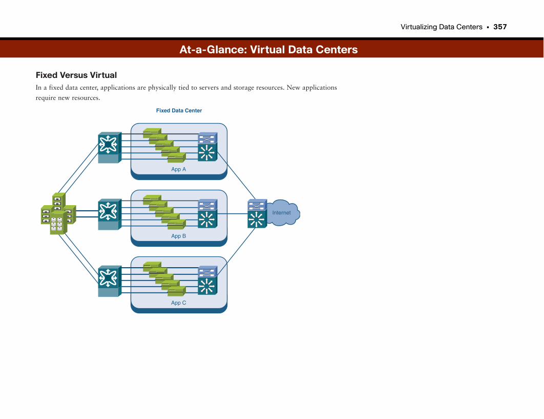
Virtualizing Data Centers • 357
Fixed Versus VirtualIn a fixed data center, applications are physically tied to servers and storage resources. New applications
require new resources.
At-a-Glance: Virtual Data Centers
App A
Fixed Data Center
Internet
App B
App C
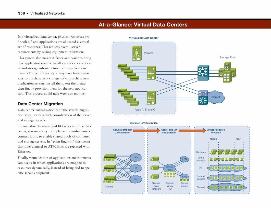
358 • Virtualized Networks
In a virtualized data center, physical resources are
“pooled,” and applications are allocated a virtual
set of resources. This reduces overall server
requirements by raising equipment utilization.
This system also makes it faster and easier to bring
new applications online by allocating existing serv-
er and storage infrastructure to the applications
using VFrame. Previously it may have been neces-
sary to purchase new storage disks, purchase new
application servers, install them, test them, and
then finally provision them for the new applica-
tion. This process could take weeks or months.
Data Center MigrationData center virtualization can take several migra-
tion steps, starting with consolidation of the server
and storage servers.
To virtualize the server and I/O services in the data
center, it is necessary to implement a unified inter-
connect fabric to enable shared pools of computer
and storage servers. In “plain English,” this means
that fiber-channel or ATM links are replaced with
Ethernet.
Finally, virtualization of applications environments
can occur, in which applications are mapped to
resources dynamically, instead of being tied to spe-
cific server equipment.
At-a-Glance: Virtual Data Centers
Virtualized Data Center
Internet
V
Apps A, B, and C
VFrame
Storage Pool
Server/ComputerConsolidation
Migration to Virtualization
LAN
IB
SAN
Servers
Server and I/OVirtualization
LAN
UnifiedFabric
DisklessServer
Hardware
Shared,Virtual
I/O
ServerImages
SAN
Virtual ResourceNetworks
Oracle SAP
Hardware
VirtualServers
I/O
NetworkServices
Storage

This page intentionally left blank
Virtualizing Network Infrastructure
Leveraging Network InvestmentAlthough businesses have become increasingly reliant on applications for pro-
ductivity, they have also become reliant on their network infrastructure. The
network enables their business models and has become engrained in everything
they do.
When a business model needs to change, often so does the network that sup-
ports it. For example, if a large bank with several hundred branches acquires
another bank, also with a few hundred branches, their applications need to
merge, and their network infrastructures need to be connected and merged.
As another example, suppose the Site Services and Security department decides
it needs to cut costs by migrating security and video surveillance systems onto
the network, instead of maintaining a separate network infrastructure.
Going back to our apartment example yet again, suppose one roommate has a
weekend visitor, so an extra place to sleep is needed. Or suppose one of the
roommates decides to start working from home. Either case means something
is likely to change inside the apartment, either temporarily or permanently. We
would like to be able to simply absorb the changes and keep the living
arrangements going.
A Network Is a NetworkOn the surface, it would seem there is not necessarily a problem. Why not just
put the new bank branches and applications on the network? Why not just
add the video camera and badge reader endpoints to the network?
One major concern is security. We may not want any random employee to be
able to access specialized applications and devices such as ATMs and security
endpoints. There also could be regulations or laws requiring proper separation
of networks during an acquisition, for example.
Another concern could be service levels. We would want to ensure that adding
more bank branches to the network is done in such a way that our existing
bank branches are not negatively impacted.
Virtualizing Network InfrastructureOne solution is to implement a Cisco network virtualization solution.
Virtualizing the network has some similarities to virtualizing the data center.
Essentially it involves decoupling the physical network equipment from the
networking services being provided.
Through network virtualization, multiple virtual networks can coexist on the
same physical network infrastructure, managed by a single IT support staff,
but with nearly complete separation of traffic and security policies.
Virtualization avoids the costs of implementing discrete network infrastruc-
tures by permitting a number of entities to securely share a single network
investment.
You may be wondering why all the people who need to use the network can’t
just plug in and use it. After all, IP networks already can accept more and
more clients.
The answers have to do with security, regulations, and service levels. Think
about our apartment example again. The four roommates can share an apart-
ment, but rules must be made about how long one person can tie up the bath-
room, who has access to the living room and when, who does the dishes, and
whether it’s all right to “borrow” each other’s food. Most likely there will also
be strict rules about not sharing toothbrushes and coffee cups, as well as
showing respect for other people’s belongings.
Network virtualization has similar challenges. Some resources, such as DHCP
services, may be fine to share. Others, such as a database of sensitive customer
information, may need to be kept private for only the department or agency
responsible for it.
362 • Virtualized Networks
Why Should I Care About Virtual Networks?Businesses make major investments in their network-
ing infrastructure, sometimes to the tune of hundreds
of millions of dollars for a single large enterprise.
Events such as mergers and acquisitions, the addition
of specialized devices and applications, guest
access, and the need for functional or department-
level domains necessitate an approach with separate
secure network partitions. Having dedicated physical
networks is cost-prohibitive. Therefore, securely
sharing a single physical networking infrastructure
is necessary.
What Problems Need to Be Solved?The coexistence of multiple network partitions on
a single physical networking infrastructure must be
planned in advance to avoid future design and per-
formance issues.
One key requirement is to plan the identification
and classification of devices connecting to the net-
work and determine how they will be assigned to
the appropriate network partition.
Within secure network partitions, traffic must be
isolated from traffic in other partitions. The
enforcement of policies must also be mapped to
network partitions such that the services and
devices within them can operate securely.
The system must also be flexible enough to handle
devices that are unmanaged, such as “guest”
The solution covers endpoint devices, through the network infrastructure, and into the data center where
services reside.
With this solution a single physical networking infrastructure investment can be leveraged for multiple
uses, raising utilization and avoiding the costs of building multiple dedicated networks.
devices, which must be categorized and treated accordingly. Unmanaged means that the IT staff do not
control the asset, such as a laptop that a guest brings onsite. It’s unreasonable to assume that the guest will
hand over his laptop to the IT staff to comply with company policy. This likely would be upsetting to the
IT staff.
High-Level DiagramThe Cisco network virtualization solution provides an end-to-end architecture that offers secure partition-
ing of the physical networking infrastructure into multiple virtual networks. These virtual networks can
support mergers and acquisitions, segregation of specialized agencies, guest networks, hosted network
services, and other applications.
At-a-Glance: Virtual Network Infrastructure
Virtual
General EmployeeNetwork
Merged NewCompany
Segregated Department(Regulatory Compliance)
Virtual
Actual Campus LAN
Virtual
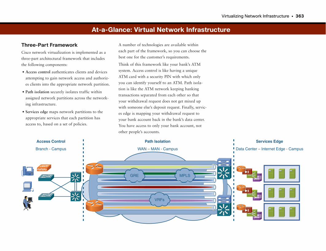
Virtualizing Network Infrastructure • 363
Three-Part FrameworkCisco network virtualization is implemented as a
three-part architectural framework that includes
the following components:
• Access control authenticates clients and devices
attempting to gain network access and authoriz-
es clients into the appropriate network partition.
• Path isolation securely isolates traffic within
assigned network partitions across the network-
ing infrastructure.
• Services edge maps network partitions to the
appropriate services that each partition has
access to, based on a set of policies.
A number of technologies are available within
each part of the framework, so you can choose the
best one for the customer’s requirements.
Think of this framework like your bank’s ATM
system. Access control is like having a unique
ATM card with a security PIN with which only
you can identify yourself to an ATM. Path isola-
tion is like the ATM network keeping banking
transactions separated from each other so that
your withdrawal request does not get mixed up
with someone else’s deposit request. Finally, servic-
es edge is mapping your withdrawal request to
your bank account back in the bank’s data center.
You have access to only your bank account, not
other people’s accounts.
At-a-Glance: Virtual Network Infrastructure
Access Control
Branch - Campus
Path Isolation
WAN – MAN - Campus
Services Edge
Data Center – Internet Edge - Campus
LWAPP
GRE MPLS
VRFs
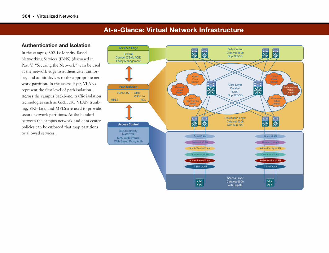
364 • Virtualized Networks
Authentication and IsolationIn the campus, 802.1x Identity-Based
Networking Services (IBNS) (discussed in
Part V, “Securing the Network”) can be used
at the network edge to authenticate, author-
ize, and admit devices to the appropriate net-
work partition. In the access layer, VLANs
represent the first level of path isolation.
Across the campus backbone, traffic isolation
technologies such as GRE, .1Q VLAN trunk-
ing, VRF-Lite, and MPLS are used to provide
secure network partitions. At the handoff
between the campus network and data center,
policies can be enforced that map partitions
to allowed services.
At-a-Glance: Virtual Network Infrastructure
ResearchVirtual
Domain
AuthenicationVirtual
Domain
Admin/Faculty Virtual
Domain
QuarantineVirtual
Domain
GuestVirtual
Domain
IT StaffVirtual
Domain
Services Edge
FirewallContext (CSM, ACE)Policy Management
Path Isolation
Access Control
IT Staff VLAN
Authentication VLAN
Quarantine VLAN
Admin/Faculty VLAN
Research VLAN
Guest VLAN
IT Staff VLAN
Authentication VLAN
Quarantine VLAN
Admin/Faculty VLAN
Research VLAN
Guest VLAN
802.1x IdentityNAC/CCA
MAC Auth BypassWeb Based Proxy Auth
VLAN/.1Q GRE VRF-Lite
MPLS ACL
Data CenterCatalyst 6500Sup 720-3B
Core LayerCatalyst
6500Sup 720-3B
Distribution LayerCatalyst 6500with Sup 720
Access LayerCatalyst 6500with Sup 32
Si
Si Si Si
Si Si
Si
Si Si Si Si
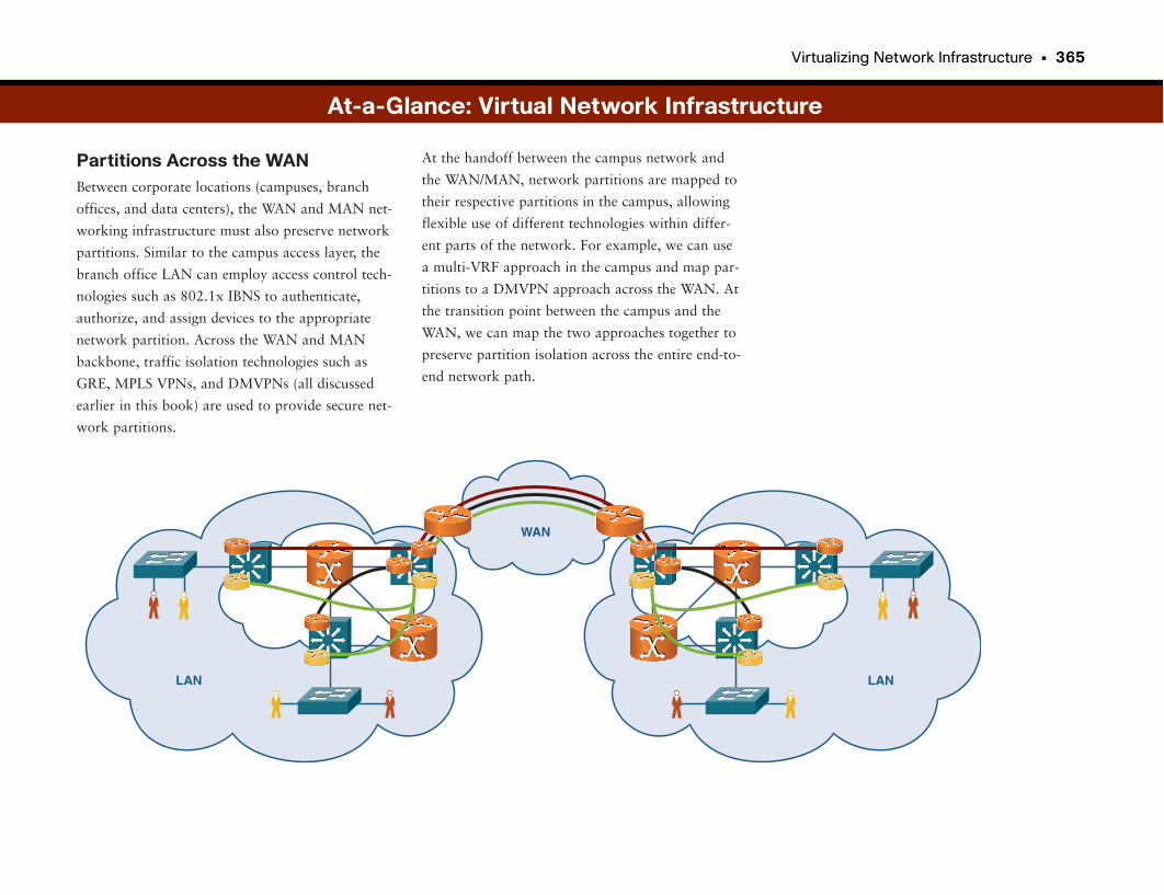
Virtualizing Network Infrastructure • 365
Partitions Across the WANBetween corporate locations (campuses, branch
offices, and data centers), the WAN and MAN net-
working infrastructure must also preserve network
partitions. Similar to the campus access layer, the
branch office LAN can employ access control tech-
nologies such as 802.1x IBNS to authenticate,
authorize, and assign devices to the appropriate
network partition. Across the WAN and MAN
backbone, traffic isolation technologies such as
GRE, MPLS VPNs, and DMVPNs (all discussed
earlier in this book) are used to provide secure net-
work partitions.
At-a-Glance: Virtual Network Infrastructure
LAN
WAN
LAN
At the handoff between the campus network and
the WAN/MAN, network partitions are mapped to
their respective partitions in the campus, allowing
flexible use of different technologies within differ-
ent parts of the network. For example, we can use
a multi-VRF approach in the campus and map par-
titions to a DMVPN approach across the WAN. At
the transition point between the campus and the
WAN, we can map the two approaches together to
preserve partition isolation across the entire end-to-
end network path.
Applications of Virtualized Networks
What Can You Do with Virtualized Networks?A number of applications exist for virtualized networks. What they have in
common is the need to have multiple entities securely share a single physical
network infrastructure. This topic discusses just a few of the use cases.
Corporate Employee “Clean” and “Dirty” NetworksWith the implementation of intelligent endpoint authentication and admission
onto the network, using solutions such as 802.1x IBNS and Network
Admission Control (NAC), there is a need to separate the “clean” endpoints,
network, and services from the “dirty.”
With virtualized networks, we can implement a “clean” network partition. As
soon as employees authenticate and ensure that their laptop or computer is
“healthy,” it is admitted to the “clean” network and has access to normal
applications. Endpoints found to be “dirty” (with a virus or other noncompli-
ance issue) are admitted only to the “dirty” network, with access only to reme-
diation services. In this type of system, each endpoint is scanned to ensure that
all virus prevention signatures (or other criteria or credentials) are up to date.
Guest and Partner NetworksBusinesses have an increasing need to support network access for guests,
whether they be customer visitors, vendors, or otherwise, and partners who
are trusted vendors or contractors critical to the business operation.
By applying network virtualization, we can identify guest and partner devices
and securely assign them to restricted network partitions. Here they may
access the Internet and perhaps a subset of appropriate applications.
Isolating Specialized Devices and ApplicationsMany devices traditionally have been connected in separate closed networks,
such as ATMs and IP video surveillance cameras on closed-circuit TV (CCTV)
networks. Many of these devices are migrating to IP networks. But it is still
desirable to keep such devices accessible to only authorized personnel.
Using network virtualization, specialized devices can be placed in private net-
work partitions, accessible only by authorized users who can authenticate and
join the same network partition as the devices.
Load BalancingUsing network virtualization, administrators can plan for changes in the network.
These changes could accommodate longer-term changes in traffic utilization,
such as the offshoring of a particular function. They also could accommodate
short-term changes, such as preparing for a conference in which a large num-
ber of users will cause spikes on local servers.
Providing Hosted Networks to Entities Within EntitiesA retail model growing in popularity is the “all service” store, in which a large
retailer hosts several other retailers inside the store property. For example, a
large grocery store may host a bank, a cell phone kiosk, a film processor, and
so on. Each of these entities needs connectivity back to its company. One
option is to have each company provide its own WAN connectivity into the
store. This could lead to a dozen or more connections into each store. Multiply
that times several hundred or thousands of stores, and costs really add up.
What if the same large retailer could host these entity-within-a-store networks,
providing the hosted companies network services using the same network
infrastructure that the hosting retailer has to have anyway for its own connec-
tivity? Furthermore, what if the large retailer could offset its own WAN con-
nection costs by charging for the hosted network services?
Using network virtualization, it is entirely possible to provide a number of pri-
vate hosted networks, with each entity having its own private partition. The
collection of partitions is mapped back over the WAN to the retailer headquar-
ters, where each aggregated connection can be mapped to a corresponding
extranet gateway and back to the hosted company’s network.
Now, whenever the retailer opens a new store location, there is no need for a
dozen entities to pursue connections of their own. The new store and its net-
work can quickly provide hosted network partitions for each of the smaller
retailers.
368 • Virtualized Networks
Departmental Virtual NetworksIncreasingly, companies are struggling to comply with a myriad of industry
and government regulations stipulating how financial and customer data is
handled and protected. Regulations including the Health Insurance Portability
and Accountability Act (HIPAA), Sarbanes-Oxley, Payment Card Industry
(PCI), and Basel II (in Europe) contain specific provisions governing the han-
dling of information. They also specify precautions that companies must take.
Network virtualization can help achieve compliance with such regulations by
restricting employee populations to application services that are appropriate
by departmental function. For example, Human Resources, Engineering,
Finance, and Manufacturing could all be assigned to respective virtual network
partitions. Data flowing between Finance and outside departments could then
be regulated—even protected with firewalls if desired.
Challenges with Virtual NetworksMany applications and collaboration systems rely on open networks—unre-
stricted communication between endpoints. Placing endpoints within virtual
network partitions by definition restricts the flow of traffic to appropriate
other endpoints and applications. The two aims (open and closed) can be dia-
metrically opposed at times, creating challenges for virtualized networks.
One of the keys in implementing virtual networks is to understand the neces-
sary traffic flows between virtual partitions and to make sure that designs
allow such communication.
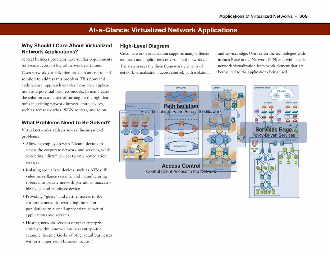
Applications of Virtualized Networks • 369
Why Should I Care About VirtualizedNetwork Applications?Several business problems have similar requirements
for secure access to logical network partitions.
Cisco network virtualization provides an end-to-end
solution to address this problem. This powerful
architectural approach enables many new applica-
tions and potential business models. In many cases
the solution is a matter of turning on the right fea-
tures in existing network infrastructure devices,
such as access switches, WAN routers, and so on.
What Problems Need to Be Solved?Virtual networks address several business-level
problems:
• Allowing employees with “clean” devices to
access the corporate network and services, while
restricting “dirty” devices to only remediation
services
• Isolating specialized devices, such as ATMs, IP
video surveillance systems, and manufacturing
robots into private network partitions, inaccessi-
ble by general employee devices
• Providing “guest” and partner access to the
corporate network, restricting these user
populations to a small appropriate subset of
applications and services
• Hosting network services of other enterprise
entities within another business entity—for
example, hosting kiosks of other retail businesses
within a larger retail business location
and services edge. Users select the technologies with-
in each Place in the Network (PIN) and within each
network virtualization framework element that are
best suited to the applications being used.
High-Level DiagramCisco network virtualization supports many different
use cases and applications of virtualized networks.
The system uses the three framework elements of
network virtualization: access control, path isolation,
Corporate OfficesBranch
InternetIPSec VPN
PSTNWAN VPN
InternetIPSec VPN
PSTN
MAN/WAN
Sonet
DWDM/CWDM
Building Y
Building X
Campus
Building Y
Building X
Campus
InternetEnterprise Edge
SP1 SP2
APPS APPS APPS APPS
Extranet Internet Edge
APPSAPPS
APPSAPPS
Data Center
PCPC
WEBAPPS
PCPC
Corporate OfficesBranch
Sonet
Building
BuildiCampus
Path IsolationProvide Isolated Paths Across the Network
Building XAccess Control
Control Client Access to the Network
APPS APPS APPS APPSAPPS
APPSAPPS
APPS
Data Center
Services EdgePolicy-Driven Services
At-a-Glance: Virtualized Network Applications
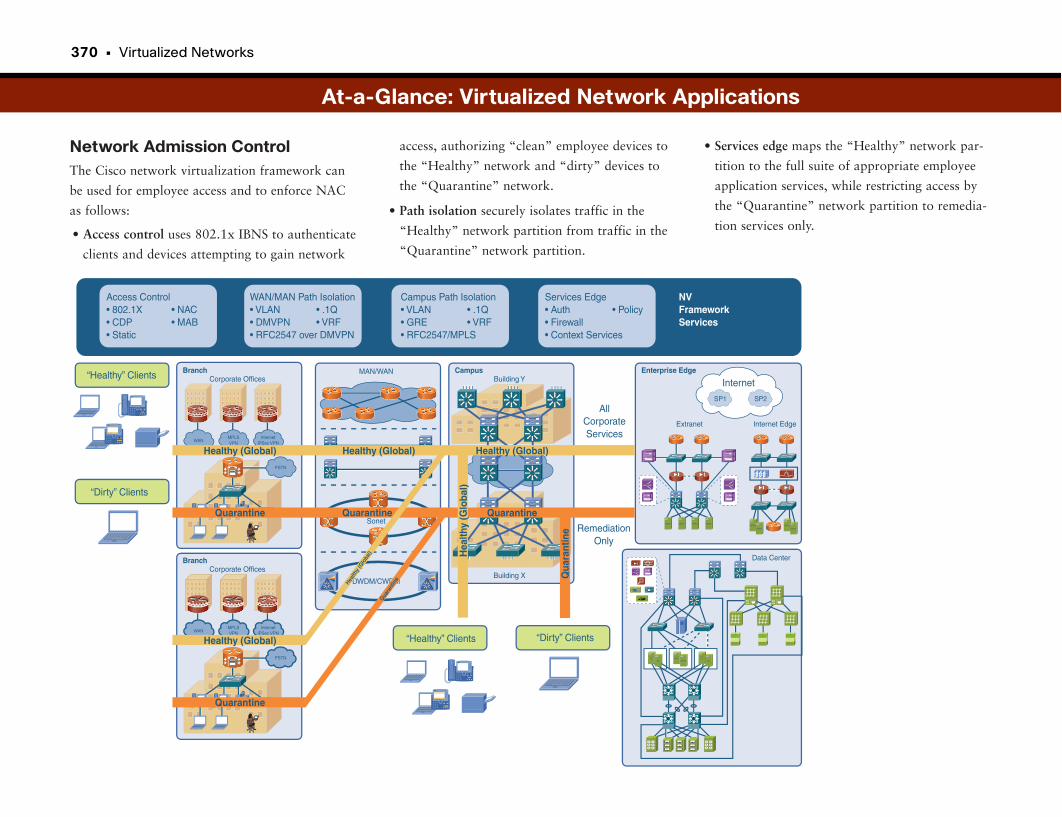
370 • Virtualized Networks
Network Admission ControlThe Cisco network virtualization framework can
be used for employee access and to enforce NAC
as follows:
• Access control uses 802.1x IBNS to authenticate
clients and devices attempting to gain network
• Services edge maps the “Healthy” network par-
tition to the full suite of appropriate employee
application services, while restricting access by
the “Quarantine” network partition to remedia-
tion services only.
access, authorizing “clean” employee devices to
the “Healthy” network and “dirty” devices to
the “Quarantine” network.
• Path isolation securely isolates traffic in the
“Healthy” network partition from traffic in the
“Quarantine” network partition.
At-a-Glance: Virtualized Network Applications
Access Control• 802.1X• CDP• Static
Services Edge• Auth• Firewall• Context Services
WAN/MAN Path Isolation• VLAN• DMVPN• RFC2547 over DMVPN
• .1Q• VRF
• NAC• MAB
• PolicyCampus Path Isolation• VLAN• GRE• RFC2547/MPLS
• .1Q• VRF
NVFrameworkServices
“Healthy” Clients
AllCorporateServices
Internet
RemediationOnly
“Dirty” Clients
WAN
Corporate OfficesBranch
MPLSVPN
InternetIPSec VPN
PSTN
Healthy (Global)
Quarantine
Building Y
Building X
Campus Enterprise EdgeMAN/WAN
Sonet
DWDM/CWDM
WAN
Corporate OfficesBranch
MPLSVPN
InternetIPSec VPN
PSTN
Healthy (Global)
Quarantine
Healthy (Global)
Quarantine
Hea
lthy
(Glo
bal)
Qua
rant
ine
Healthy (Global)
Quarantine
Health
y (G
loba
l)
Quara
ntin
eSP1 SP2
APPS APPS APPS APPS
Extranet Internet Edge
Data Center
APPSAPPS
APPSAPPS
PCPC
WEBAPPS
PCPC
“Healthy” Clients “Dirty” Clients
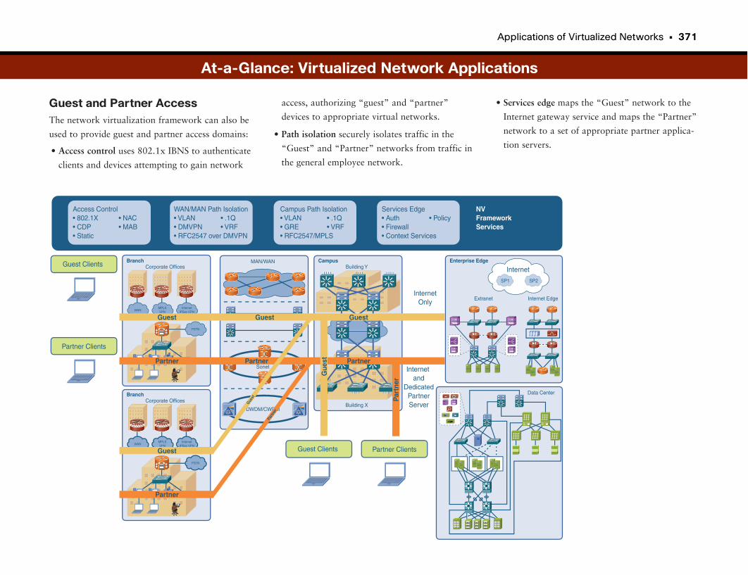
Applications of Virtualized Networks • 371
Guest and Partner AccessThe network virtualization framework can also be
used to provide guest and partner access domains:
• Access control uses 802.1x IBNS to authenticate
clients and devices attempting to gain network
• Services edge maps the “Guest” network to the
Internet gateway service and maps the “Partner”
network to a set of appropriate partner applica-
tion servers.
access, authorizing “guest” and “partner”
devices to appropriate virtual networks.
• Path isolation securely isolates traffic in the
“Guest” and “Partner” networks from traffic in
the general employee network.
Access Control• 802.1X• CDP• Static
Services Edge• Auth• Firewall• Context Services
WAN/MAN Path Isolation• VLAN• DMVPN• RFC2547 over DMVPN
• .1Q• VRF
• NAC• MAB
• PolicyCampus Path Isolation• VLAN• GRE• RFC2547/MPLS
• .1Q• VRF
NVFrameworkServices
Guest Clients
InternetOnly
Internet
Internet and
DedicatedPartnerServer
Partner Clients
WAN
Corporate OfficesBranch
MPLSVPN
InternetIPSec VPN
PSTN
Guest Clients Partner Clients
Guest
Partner
Building Y
Building X
Campus Enterprise EdgeMAN/WAN
Sonet
DWDM/CWDM
WAN
Corporate OfficesBranch
MPLSVPN
InternetIPSec VPN
PSTN
Guest
Partner
Guest
Partner
Gue
st
Par
tner
Guest
Partner
Guest
Partn
er
SP1 SP2
APPS APPS APPS APPS
Extranet Internet Edge
Data Center
APPSAPPS
APPSAPPS
PCPC
WEBAPPS
PCPC
At-a-Glance: Virtualized Network Applications
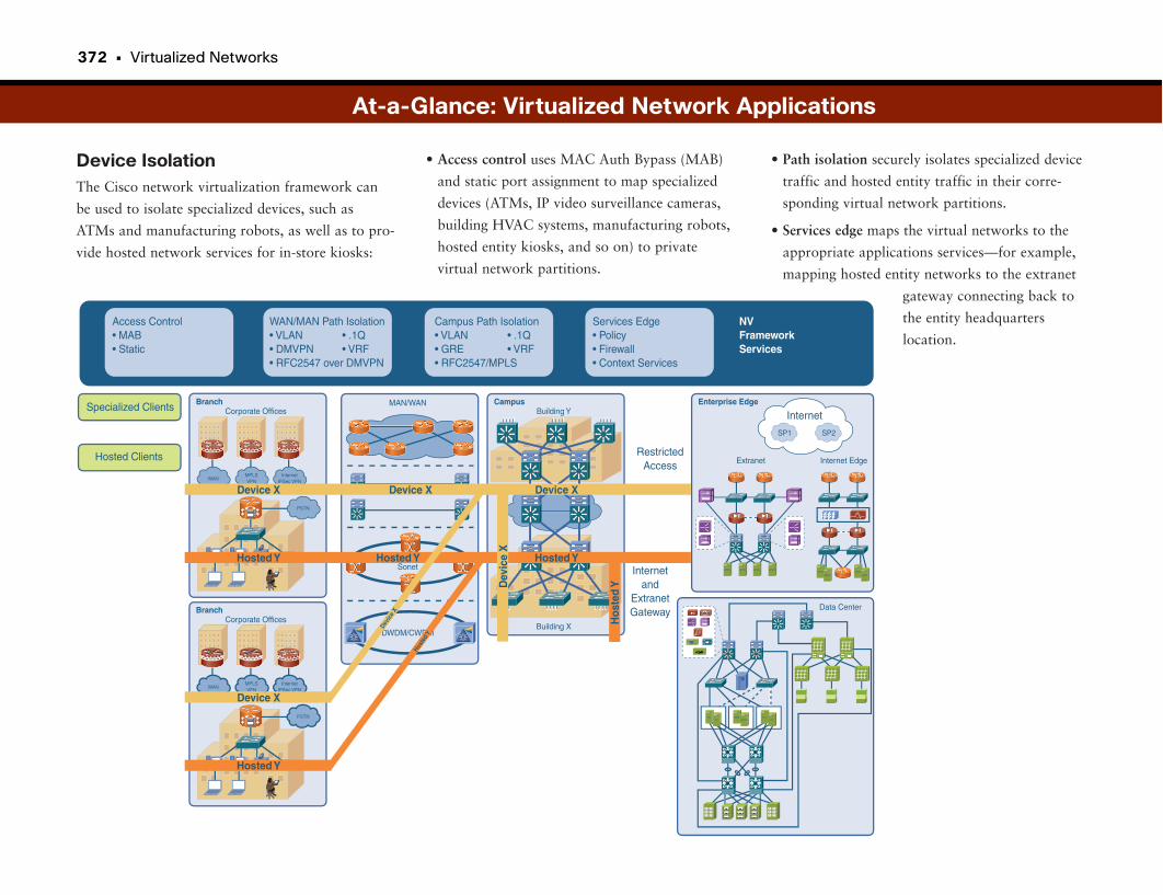
372 • Virtualized Networks
Device IsolationThe Cisco network virtualization framework can
be used to isolate specialized devices, such as
ATMs and manufacturing robots, as well as to pro-
vide hosted network services for in-store kiosks:
At-a-Glance: Virtualized Network Applications
• Access control uses MAC Auth Bypass (MAB)
and static port assignment to map specialized
devices (ATMs, IP video surveillance cameras,
building HVAC systems, manufacturing robots,
hosted entity kiosks, and so on) to private
virtual network partitions.
• Path isolation securely isolates specialized device
traffic and hosted entity traffic in their corre-
sponding virtual network partitions.
• Services edge maps the virtual networks to the
appropriate applications services—for example,
mapping hosted entity networks to the extranet
gateway connecting back to
the entity headquarters
location.Access Control• MAB• Static
Services Edge• Policy• Firewall• Context Services
WAN/MAN Path Isolation• VLAN• DMVPN• RFC2547 over DMVPN
• .1Q• VRF
Campus Path Isolation• VLAN• GRE• RFC2547/MPLS
• .1Q• VRF
NVFrameworkServices
Specialized Clients
RestrictedAccess
Internet
Internetand
ExtranetGateway
Hosted Clients
WAN
Corporate OfficesBranch
MPLSVPN
InternetIPSec VPN
PSTN
Device X
Hosted Y
Building Y
Building X
Campus Enterprise EdgeMAN/WAN
Sonet
DWDM/CWDM
WAN
Corporate OfficesBranch
MPLSVPN
InternetIPSec VPN
PSTN
Device X
Hosted Y
Device X
Hosted Y
Dev
ice
X
Hos
ted
Y
Device X
Hosted Y
Devic
e X
Hoste
dY
SP1 SP2
APPS APPS APPS APPS
Extranet Internet Edge
Data Center
APPSAPPS
APPSAPPS
PCPC
WEBAPPS
PCPC
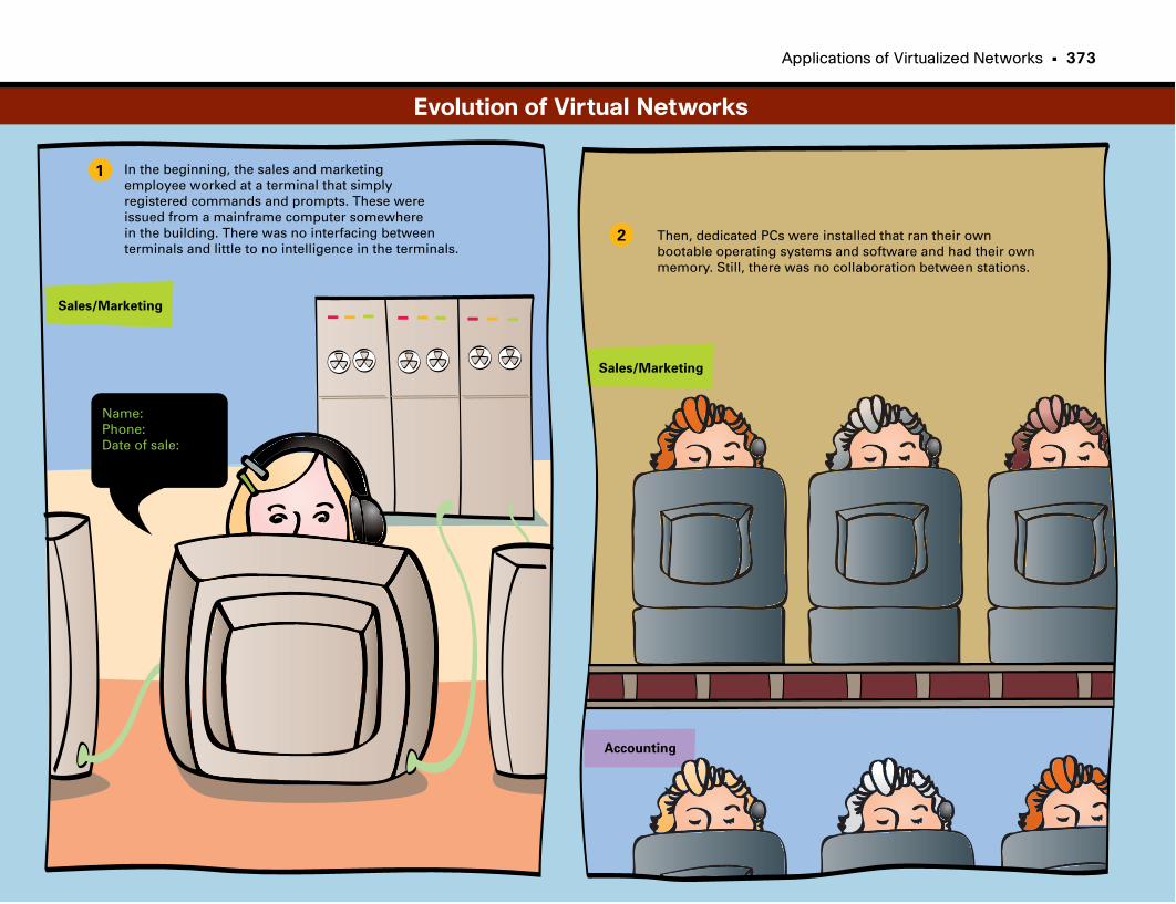
Applications of Virtualized Networks • 373
1
2
In the beginning, the sales and marketingemployee worked at a terminal that simply registered commands and prompts. These were issued from a mainframe computer somewhere in the building. There was no interfacing betweenterminals and little to no intelligence in the terminals.
Name:Phone:Date of sale:
Sales/Marketing
Sales/Marketing
Accounting
Then, dedicated PCs were installed that ran their ownbootable operating systems and software and had their ownmemory. Still, there was no collaboration between stations.
Evolution of Virtual Networks
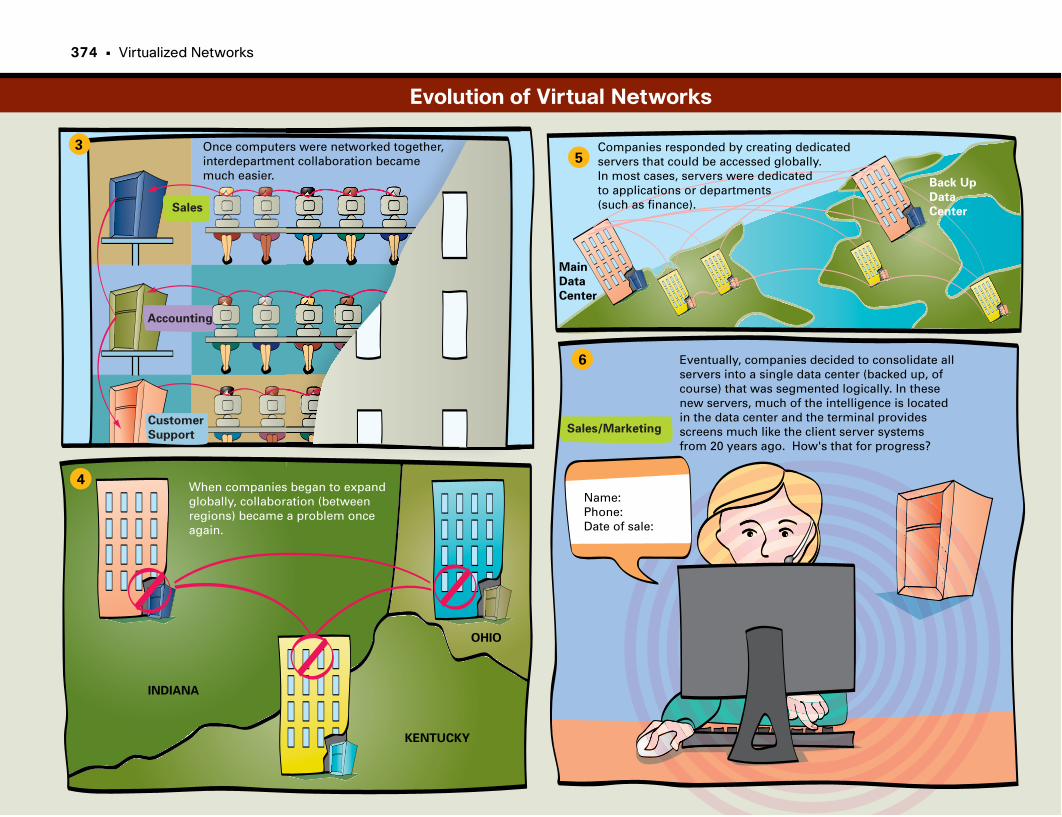
3
4
5
6
Once computers were networked together, interdepartment collaboration became much easier.
Sales
Sales/Marketing
Accounting
Customer
Support
INDIANA
KENTUCKY
OHIO
When companies began to expandglobally, collaboration (betweenregions) became a problem onceagain.
Companies responded by creating dedicated servers that could be accessed globally. In most cases, servers were dedicated to applications or departments(such as finance).
Main
Data
Center
Back Up
Data
Center
Name:Phone:Date of sale:
Eventually, companies decided to consolidate all servers into a single data center (backed up, of course) that was segmented logically. In these new servers, much of the intelligence is located in the data center and the terminal provides screens much like the client server systems from 20 years ago. How's that for progress?
Evolution of Virtual Networks
374 • Virtualized Networks

This page intentionally left blank
Index

subnet, 21
switches, learning, 46
administration, 147
documentation, 148
importance, 150
mobility, 151
problems, 150
process frameworks, 147–148
protocols, 148–149
troubleshooting tools, 149
ADSL (Asymmetric DSL), 86
Advanced Encryption Standard (AES), 100
advantages
broadband, 85
cable modems, 91
DSL, 90
IPv6, 22
Layer 3 routed networks, 49
OSI, 7
unified communications, 277
videoconferencing, 289
virtualized data centers, 355
VPNs, 95
wireless networking, 313
AES (Advanced Encryption Standard), 100
aggregation (data centers), 223
aging out, 46
Algebraic Code-Excited Linear Prediction (ACELP),
263
analog-to-digital conversions, 261–262
anarchists, 162
anomalies, detecting, 213
ANSI (American National Standards Institute), 231
Any Transport over MPLS (AToM), 81
appliance-based clean access, 196
Symbols3DES (Triple Data Encryption Standard), 100
24/7/365 availability, 121
99.999 percent availability, 124
802.11b/802.11g/802.11n, 321
802.1x, 187–188
@ (at symbol), 27
AAAA (Authentication, Authorization, and Accounting),
227
access
attacks, combating, 181
control, WLANs, 315
guest, 343
configuring, 345
importance, 344
problems, 344
SSID, 344
Unified Wireless solution, 344
virtualized networks, 371
Internet
broadband, 85–90
ISDN, 87
limiting, 189
methods, 231–232
remote, 93–95
unwanted, preventing, 189
wireless networks, 325
access control lists. See ACLs
access layer (campus networks), 65
access points. See APs
ACD (automatic call distribution), 297
ACELP (Algebraic Code-Excited Linear Prediction),
263
ACLs (access control lists)
data centers, 227
perimeter security, 160
active attacks, 161
active monitoring, 179
Address Resolution Protocol (ARP), 16, 182–183
addresses
e-mail, 27
IP, 13
classes, 19–20
diminishing availability, 22
domain names, 14
dotted-decimal notation, 13–14, 19
dynamic, 14
hosts/networks, 19
importance, 19
problems, 19
spoofing, 182–183
subnet addresses, 21
subnet masks, 20–21
subnets, 20
IPv4, 22
IPv6, 22
advantages, 22
autoconfiguration, 23
migration, 24
mobile devices, 23
notation, 22
security, 23
logical, 19
MAC, 13
flooding, 182–183
instability, 51
physical, 19
378 • application layers
application layers
encryption, 102
OSI, 6–7
unified communications, 258–259, 266
application servers, centralizing, 249
applications. See also software
data centers, 223
Internet
e-mail, 27–28
web browsing, 28–29
virtualized networks, 367
challenges, 368
clean/dirty endpoints, 367
departmental regulation compliance, 368
device isolation, 372
framework solution, 369–370
guest/partner access, 367, 371
importance, 369
load balancing, 367
network admission control, 370
private entities, hosting, 367
problems, 369
specialized devices, isolating, 367
APs (access points), 313
municipal wireless, 333
roaming WLANs, 315
rogue, 162, 320, 325–328
architecture
branch offices, 114
MPLS, 80
VPNs, 95–96
ARP (Address Resolution Protocol), 16, 182–183
assets (wireless), finding, 347
location-based services, 348–349
monitoring, 350
planning, 350
RFID, 347
Asymmetric DSL (ADSL), 86
asynchronous transmission (ATM networks), 76
at symbol (@), 27
ATM networks, 72
asynchronous transmission, 76
connections, 77
endpoints, 72, 76
fixed cell size, 77
importance, 76
interfaces, 76
LANE, 77
problems, 76
switches, 72, 76
virtual connections, 77
AToM (Any Transport over MPLS), 81
attacks
access, combating, 181
active, 161
blocked by firewalls, 169
DoS, 162
false positives, 177
hit-and-run, 161
internal, 162
man-in-the-middle, 161
passive, 161
remote, 161
rogue access points, 162
sneak, 179
sources, 211–213
attenuation, 109
audioconferencing, 280
authentication
network infrastructure virtualization, 364
servers, 190
Authentication, Authorization, and Accounting (AAA),
227
auto-configuration (IPv6), 23
automatic call distribution (ACD), 297
availability. See high availability
Bback doors, 162
back-end congestion notification (BECN), 72
back end functions (data centers), 223
backbone, 65
backups
availability, 122–123
data centers, 223
dial, 71
disaster recovery, 143
Backward Explicit Congestion Notification (BECN),
75
bad packets, 171
bandwidth
conservation for VoIP, 262–263
Ethernet, 38
low-bandwidth tools, 272
videoconferencing, 284
baselining, 213
basic bridging, 43
Basic Rate Interface (BRI), 85–87
BECN (back-end congestion notification), 72
BGP (Border Gateway Protocol), 55
botnets, 163
Cisco Unified Personal Communicator (CUPC) • 379
BPDU (bridge protocol data units), 49
branch office designs, 113–115, 243
architecture, 114
communications, 116–117
distributed offices, 113
distributed workforce, 113
importance, 114
problems, 114
scaling, 114
security, 115–116
storage centralization, 243
WAFS, 243
caching, 245–246
file engine, 244–245
importance, 244
problems, 244
transparency, 245
BRI (Basic Rate Interface), 85–87
bridge protocol data units (BPDU), 49
bridges
basic, 43
Ethernet, 36–38
as firewalls, 43
LANs, 43
routers as, 56
switches, compared, 43–44
transparent, 43
types, 43
wireless, 313
broadband
advantages over dialup, 85
cable, 85–86, 90–91
choosing, 86
DSL, 85, 89–90
importance, 89
overview, 85
problems, 89
speed, 89
technology evolution, 85
WANs, 73
broadcast domains, 45
broadcast storms, 51
browsing (web), 28–29
building WLANs, 314–315
building-to-building bridge systems, 314
CCable Modem Termination System (CMTS), 91
cable modems, 85, 90
advantages, 91
DSL, compared, 86
equipment, 91
limitations, 91
cables
availability, 122, 125
Ethernet, 35
CAC (Call Admission Control), 339
caching, 28, 221, 239
content freshness, 240
disk to memory, 240
load limits, 240
overview, 239
problems, 240
video/audio files, 239
WAFS, 245–246
call processing layer, 258–259, 266
CallManager (CM), 258–259, 299
CAM (Clean Access Manager), 196
campus networks, 65
hierarchical, 65
high availability, 67
importance, 66
oversubscription, 67
redundancy, 67
services, 69
size, 67–69
carrier sense multiple access/collision detect
(CSMA/CD) protocol, 35
CAS (Clean Access Server), 196
causes
disaster recovery, 141
network unavailability, 121–124
CCA (Cisco Clean Access), 326
CCTV (closed-circuit TV), 215
CDPD (Cellular Digital Packet Data), 332
centralizing
applications, 249
storage, 243
CGMP (Cisco Group Management Protocol), 308
change control management, 122, 126
choosing
broadband connections, 86
e-mail addresses, 27
chromatic distortion, 109
CIPS (Cisco Intrusion Prevention System), 178
circuit switching, 71
Cisco Clean Access (CCA), 326
Cisco Group Management Protocol (CGMP), 308
Cisco Intrusion Prevention System (CIPS), 178
Cisco Secure Agent (CSA), 326
Cisco Unified Personal Communicator (CUPC), 275

380 • citywide wireless
citywide wireless, 331–334
access points, 333
importance, 332
legacy wide-area wireless data networks, 332
Outdoor Wireless Mesh, 332
portable devices, 332
problems, 332
security, 334
wireless backhauls, 333
classes (IP addresses), 19–20
Clean Access Manager (CAM), 196
Clean Access Server (CAS), 196
clean implementations, 122–125
clean nets, 171
client layer, 257–258, 266
client/server models, 226
closed-circuit TV (CCTV), 215
CM (CallManager), 299
CMTS (Cable Modem Termination System), 91
coarse wavelength division multiplexing (CWDM), 110
collisions, 20, 37
comfort noise (VoIP), 263
communications
audioconferencing, 280
branch offices, 116–117
IP call centers, 297
anatomy, 297
call flow examples, 299–300
components, 297
customer interaction methods, 298
equipment, 299
importance, 299
inbound calls, 297–298
managing, 298
migrating from east to west, 300
outbound calls, 298
problems, 299
remote workers, 300
routing to specialized agents, 300
location services, 294
managing
location services. See location services
presence, 293
meeting collaboration
importance, 280
instant messaging integration, 281
MeetingPlace solution, 280
meetings as activities, 279
problems, 280
scheduling application integration, 280
spaces, 279
Telepresence, 289–291
videoconferencing, 281–285, 289
models
open-source, 5
OSI, 5–9
proprietary, 5
Presence, 295
QoS, 269
classification, 272
importance, 271
jitter, 271
latency, 271
loss, 271
low-bandwidth tools, 272
MOS, 270
provisioning, 271
scheduling, 272
unified, 257
advantages, 277
application layer, 258-259, 266
call processing layer, 258-259, 266
client layer, 257–258, 266
convergence, 257, 275
CUPC, 275
deployment, 259–260
device convergence, 275
importance, 265, 276
infrastructure layer, 258, 266
IP phone calls, placing, 265
jitter, 270
latency, 270
layers, 257
loss, 269
management capabilities, 277
overview, 266
problems, 265, 276
productivity, increasing, 277
QoS, 269–270
solution, 276
toll bypass, 265
types of communication, 275
VoIP
analog-to-digital conversions, 261–262
bandwidth conservation, 262–263
codecs, 263
comfort noise, 263
importance, 261
packet transportation, 261
complexity, reducing, 125
compressing voice, 262–263
computer health
assessing, 193
NAC, 194–196
data centers • 381
computer telephony integration (CTI), 297–299
configuring wireless guest access, 345
congestion notification, 75
connections
ATM networks, 77
Internet. See broadband
MPLS, 78
multipoint, 291
TCP, 16
VPNs, 93
WANs, 71
ATM. See ATM networks
broadband, 73, 85
circuit switching, 71
Frame Relay, 72–74
ISDN, 71, 87
MPLS, 73, 78
packet switching, 71
point-to-point, 71
virtual circuits, 71
VPNs, 73, 93
consistent uptime (availability), 123
console messages, 148
contact centers, 297
anatomy, 297
call flow examples, 299–300
components, 297
customer interaction methods, 298
equipment, 299
importance, 299
inbound calls, 297–298
managing, 298
migrating from east to west, 300
outbound calls, 298
problems, 299
remote workers, 300
routing to specialized agents, 300
content freshness (caching), 240
control plane, 129–131
Control Plane Protection Policing (CoPP), 129–131
convergence
QoS, 269
unified communications, 275
CoPP (Control Plane Protection Policing), 129
dedicated processors, 131
implementing, 130
importance, 130
overview, 130
problems, 130
core layer, 65
corporate Internet usage policies, 199
corporate WLANs. See WLANs
costs
downtime, 124
routers, 57
videoconferencing, 283
CPE (Customer Premises Equipment), 73, 79
crackers, 162
CRM (customer resource management), 223
CSA (Cisco Secure Agent), 326
CSMA/CD (carrier sense multiple access/collision
detect) protocol, 35
CTI (computer telephony integration), 297–299
CUPC (Cisco Unified Personal Communicator), 275
cut-through switching mode, 46
CWDM (coarse wavelength division multiplexing), 110
DDaemen, Joan, 100
DARPA (Defense Advanced Research Projects Agency),
13
DAS (directly attached storage), 231
data
caching, 221
de-encapsulation, 9
encapsulation, 9
privacy, 157, 160
data centers
aggregation, 223
application servers, centralizing, 249
applications, 223
back end, 223
backups, 223
branch offices, 243
caching, 221
content freshness, 240
disk to memory, 240
load limits, 240
overview, 239
problems, 240
video/audio files, 239
distribution, 226
facilities, 227
front end, 223
functions, 223
high availability, 224
importance, 225
layers, 225–226
managing, 227
n-tier models, 223
network transport, 223
382 • data centers
overview, 223
problems, 225
requirements, 224
SANs, 221
scalability, 224
security, 224, 227
storage, 223, 227
importance, 233
NAS, 234–235
overview, 233
problems, 233
SANs. See SANs
technologies, 234
traditional server-centric storage methods, 233
traditional client/server model, 226
types, 225
virtualization, 224
advantages, 355
data center virtualization solution, 356
fixed data centers, compared, 357–358
importance, 356
migration, 358
overview, 355
problems, 356
WAAS, 249
data redundancy elimination, 252
importance, 250
overview, 250
problems, 250
TCP compatibility, 251
transparency, 250–251
data communications equipment (DCE), 74
Data Encryption Standard (DES), 100
data flow layers (OSI), 7
data link connection identifiers (DLCI), 72, 75
data link layers, 6, 102
data plane, 129
data read caching, 245
Data Redundancy Elimination (DRE), 252
data terminal equipment (DTE), 72–74
datagrams, 16
DCE (data communications equipment), 74
DDoS (Distributed DoS), 162
DDR (dial-on-demand routing), 71
dedicated processors, 131
de-encapsulation, 9
deep packet inspections, 205
catalyst example, 208
importance, 206
overview, 207
problems, 206
defects per million (DPM), 124
Defense Advanced Research Projects Agency (DARPA),
13
delays (routers), 57
demilitarized zone (DMZ), 169
Denial of Service (DoS), 162
dense wavelength division multiplexing (DWDM),
107–108, 111
deployment
IDSs, 178
unified communications, 259–260
VPNs, 95
DES (Data Encryption Standard), 100
designing
branch offices, 113–115
architecture, 114
communications, 116–117
distributed offices, 113
distributed workforce, 113
importance, 114
problems, 114
scaling, 114
security, 115–116
campus networks, 65
high availability, 67
importance, 66
oversubscription, 67
redundancy, 67
size, 67–69
high availability, 124
metro optical technologies, 109–110
wireless networks, 319
WLANs, 322
DHCP (Dynamic Host Configuration Protocol), 14
DHCP servers, 182–183
dial backups, 71
dial-on-demand routing (DDR), 71
dialup services, 71
Diffie-Hellman Key Exchange, 101
digital signal processing (DSP), 258
digital subscriber line (DSL), 85–86, 89–90
digital surveillance systems, 216
Direct Sequence Spread Spectrum (DSS), 315
directly attached storage (DAS), 231
dirty nets, 172
disaster recovery
backups, 143
business resiliency, 140
causes, 141
fires, 139
importance, 141
normal operations, 143
overview, 139
planning, 139, 142
Ethernet • 383
preparedness testing, 140, 143
primary systems, restoring, 143
problems, 141
risk assessments, 142
discovery, 59
dispersion, 109
distance accumulation, 58
distance vector routing, 58–59
Distributed DoS (DDoS), 162
distributed offices, 113
distributed workforce, 113
distribution layer, 65
distribution trees, 307
DIX standard (Ethernet), 35
DLCIs (data link connection identifiers), 72, 75
DMVPNs (dynamic multipoint VPNs), 96–97
DMZ (demilitarized zone), 169
DNS (Domain Name System), 14
documentation, 148
Domain Name System (DNS), 14
domains
broadcast, 45
collision, 20, 37
names, 14, 27
DoS (Denial of Service), 162
dotted-decimal notation, 13–14, 19
downtime
costs, 124
measuring, 121
per year measurements, 121
DPI (deep packet inspection), 205
catalyst example, 208
importance, 206
overview, 207
problems, 206
DPM (defects per million), 124
DPT (dynamic packet transport), 107–108
DRE (Data Redundancy Elimination), 252
DSL (digital subscriber line), 85–86, 89–90
DSP (digital signal processing), 258
DSS (Direct Sequence Spread Spectrum), 315
DTE (data terminal equipment), 72–74
duplicate frames, 51
DWDM (dense wavelength division multiplexing),
107–108, 111
Dynamic Host Configuration Protocol (DHCP), 14
dynamic IP addresses, 14
dynamic multipoint VPNs (DMVPNs), 96–97
dynamic packet transport (DPT), 107–108
dynamic routes, 57
EEAP (Extensible Authentication Protocol), 188, 326
EGP (Exterior Gateway Protocols), 58
EIGRP (Enhanced Interior Gateway Routing Protocol),
55
e-mail, 27
addresses, 27
clients, 27
domain names, 27
receiving, 28
recipients, 27
sending, 28
web-based, 27
encapsulation, 9, 78
encryption
export laws, 100
importance, 100
keys, 101
layers, 102
packets, 205
problems, 100
standards, 100
VPNs, 95
wireless, 326
endpoints, 72, 76
enforcing security policies, 158–160
engineering traffic, 272
Enhanced Interior Gateway Routing Protocol (EIGRP),
55
enterprise resource planning (ERP), 223
equipment. See hardware
ERP (enterprise resource planning), 223
Ethernet
bandwidth, increasing, 38
bridges, 36–38
cables, 35
collisions, 37
distance limitations, 36
DIX standard, 35
evolution, 36
full duplex, 36
history, 35
hubs, 36–38
importance, 37
LAN routers, 38
LAN switches, 38
naming, 35
optical, 110
overview, 35–36
problems, 37
repeaters, 38
segmenting, 37–38
switches, 36, 44
Token Ring, 35
384 • Extensible Authentication Protocol (EAP)
Extensible Authentication Protocol (EAP), 188, 326
Exterior Gateway Protocols (EGP), 58
external security attacks, 159
extranets
server farms, 225
VPNs, 93
Ffacilities (data centers), 227
factoring, 101
false positive attacks, 177
FAST (Flexible Authentication via Secure Tunnel), 326
fault tolerance, 231
FCAPS (Fault, Configuration, Accounting,
Performance, and Security), 147–148
FCIP (Fiber Channel over IP), 232
FEC (Forwarding Equivalence Classes), 80
FECN (front-end congestion notification), 72, 75
fiber-based MANs, 107
fiber channel, 231–232, 234
Fiber Channel over IP (FCIP), 232
Fiber-Optic Transmission Systems (FOTS), 107
file engine, 244–245
filters
inside, 171
outside, 172
server-side, 28
SRTBH, 213
switches, 45
URL filtering, 199
black/white lists, 201
importance, 200
overview, 200
problems, 200
third-party servers, 201
finding wireless assets, 347
location-based services, 348–349
monitoring, 350
planning, 350
RFID, 347
firewalls, 169
bad packets, 171
clean nets, 171
dirty nets, 172
DMZ, 169
function, 171
good packets, 171
hackers, 172
importance, 171
inside filters, 171
isolation LANs, 171
outside filters, 172
personal, 170
problems, 171
protection provided, 169
first-order traffic anomalies, 135
five nines availability, 124
flat Earth popularity, 49
flat networks, 57
Flexible Authentication via Secure Tunnel (FAST), 326
flooding, 44–46, 182–183
Forward Explicit Congestion Notification (FECN), 75
forwarding
multicast, 308
packets, 55
ports, 50
switches, 46
Forwarding Equivalence Classes (FEC), 80
FOTS (Fiber-Optic Transmission Systems), 107
fragment-free switching mode, 46
Frame Relay, 72
congestion, 72, 75
DLCIs, 75
equipment, 74
importance, 74
LMIs, 75
performance, 75
problems, 74
virtual circuits, 74–75
frames
duplicate, 51
switching modes, 46
front-end congestion notification (FECN), 72
front end functions, 223
full duplex, 36
functions
control plane, 130
data centers, 223
firewalls, 171
identities, 188
NAC, 195–196
telemetry, 212
Ggateways, 258
GRE (generic routing encapsulation), 96
guest access
virtualized networks, 371
wireless, 343
configuring, 345
importance, 344
problems, 344
SSID, 344
Unified Wireless solution, 344

hit-and-run attacks • 385
HH.323 protocol, 283–284
hacking, 161
active attacks, 161
anarchists, 162
back doors, 162
botnets, 163
breaking in, 161
breaking stuff, 161
calling cards, 161
crackers, 162
DoS, 162
firewalls, 172
hit-and-run attacks, 161
internal attacks, 162
man-in-the-middle attacks, 161
passive attacks, 161
remote attacks, 161
rogue access points, 162
script kiddies, 162
sniffing/spoofing, 163
stealing stuff, 161
Trojan horses, 162
viruses/worms, 162
half duplex, 36
hardware
availability, 125
cable modems, 91
contact centers, 299
DSL, 90
errors, 124
Frame Relay, 74
health
assessing, 193
NAC, 194–196
ISDN, 88
MPLS, 79
redundancy, 122
videoconferencing, 284
hashes, 101
health (devices)
assessing, 193
NAC, 194
appliance-based clean access, 196
functions, 195–196
importance, 195
network-based clean access, 196
problems, 195
WLANs, 327
hexadecimal numbers, 13
hierarchy
campus networks, 65–66
routers, 58
high availability, 121
24/7/365, 121
campus networks, 67
causes of failures, 124
change control management, 126
clean implementations, 125
complexity, reducing, 125
consistent uptime, 123
Control Plane Protection, 129
dedicated processors, 131
implementing, 130
importance, 130
overview, 130
problems, 130
data centers, 224
designing, 124
disaster recovery
backups, 143
business resiliency, 140
causes, 141
fires, 139
importance, 141
normal operations, 143
overview, 139
planning, 139, 142
preparedness testing, 140, 143
primary systems, restoring, 143
problems, 141
risk assessments, 142
downtime, 121, 124
five nines, 124
hardware, 125
importance, 124
increasing, 122–123
measuring, 121, 124
network monitoring, 125
QoS, 133
first-order traffic anomalies, 135
normal traffic, 134–135
overview, 134
resiliency, 134
scavenger, 133
second-order traffic anomalies, 136
traffic management, 134
redundancy, 126
security, 126
service providers, 125
software, 125
training for, 126
unavailability causes, 121–122
hit-and-run attacks, 161
386 • home WLANs
home WLANs, 314
hop counts, 57
hosts, isolating, 213
HSRP (Hot Standby Router Protocol), 65, 125
HTML (Hypertext Markup Language), 29
HTTP (Hypertext Transfer Protocol), 29
hub-and-spoke DMVPN, 97
hubs, 36–38
IIBNS (Identity-Based Networking Services, 187
ICM (intelligent call management), 299
ICMP (Internet Control Message Protocol), 16
identities, 157
802.1x, 188
access limitations, 189
authentication servers, 190
EAP, 188
establishing, 159–160
function, 188
importance, 188
PKI, 190
problems, 188
RADIUS, 190
unwanted access, preventing, 189
user-based service provisioning, 190
Identity-Based Networking Services (IBNS), 187
IDS (Intrusion Detection System), 177, 227, 326
data centers, 227
deploying, 178
false positive attacks, 177
importance, 178
IPS, 177
passive monitoring, 179
problems, 178
sneak attacks, 179
IEEE (Institute of Electrical and Electronic Engineers),
5
IGMP (Internet Group Management Protocol),
305–308
IGP (Interior Gateway Protocol), 58
IKE (Internet Key Exchange), 94
IMAP (Internet Mail Access Protocol), 28
inbound calls (contact centers), 297–298
increasing
availability, 122–123
bandwidth, 38
Infiniband, 232
Information Technology Infrastructure Library (ITIL),
147–148
infrastructure layer, 258, 266
inside filters, 171
Institute of Electrical and Electronic Engineers (IEEE),
5
Integrated Services, 71
intelligent call management (ICM), 299
intelligent rerouting, 81
interactive voice response (IVR), 297
interdomain routing, 58
interfaces
ATM networks, 76
ISDN, 87
Interior Gateway Protocol (IGP), 58
internal attacks, 159, 162
International Organization for Standardization (ISO),
5
International Telecommunications Union (ITU), 283
Internet
broadband
advantages over dialup, 85
cable modems, 85–86, 90–91
choosing, 86
DSL, 85, 89–90
importance, 89
overview, 85
problems, 89
speed, 89
technologies, 85
WANs, 73
browsing, 28–29
connection speeds, 89
e-mail, 27
addresses, 27
clients, 27
domain names, 27
receiving, 28
recipients, 27
sending, 28
web-based, 27
ISDN, 87
protocols, 16. See also TCP/IP
security, 157, 199
server farms, 225
Internet Control Message Protocol (ICMP), 16
Internet Group Management Protocol (IGMP),
305–308
Internet Key Exchange (IKE), 94
Internet Protocol. See IP
intradomain routing, 58
intranet server farms, 225
Intrusion Detection System. See IDS
LANs • 387
IP (Internet Protocol), 13
addresses, 13
classes, 19–20
diminishing availability, 22
domain names, 14
dotted-decimal notation, 13–14, 19
dynamic, 14
hosts/networks, 19
importance, 19
IPv4, 22
IPv6, 22–24
problems, 19
spoofing, 182–183
subnets, 20–21
call centers, 297
anatomy, 297
call flow examples, 299–300
components, 297
customer interaction methods, 298
equipment, 299
importance, 299
inbound calls, 297–298
managing, 298
migrating from east to west, 300
outbound calls, 298
problems, 299
remote workers, 300
routing to specialized agents, 300
enabled video, 217
multicast, 305–306
CGMP, 308
distribution trees, 307
forwarding, 308
IGMP, 307–308
importance, 307
Layer 2, 308
PIM, 308
problems, 307
networks
Telepresence over, 290–291
videoconferencing over, 283
phone calls, placing, 265
SANs access, 232
SCSI (iSCSI), 227, 234
telephony, 265
version 4 (IPv4), 22
version 6 (IPv6), 22
advantages, 22
autoconfiguration, 23
migration, 24
mobile devices, 23
notation, 22
security, 23
IPS (Intrusion Prevention Systems), 177
active monitoring, 179
false positive attacks, 177
IPsec, 23, 96
IPv4 (IP version 4), 22
IPv6 (IP version 6), 22
advantages, 22
autoconfiguration, 23
migration, 24
mobile devices, 23
notation, 22
security, 23
iSCSI (IP SCSI), 227, 234
ISDN (Integrated Services Digital Network), 71, 85
calls, initiating, 88
equipment, 88
importance, 87
interfaces, 87
Internet access, 87
problems, 87
WANs, 71
ISO (International Organization for Standardization), 5
isolation
hosts, 213
LANs, 171
network infrastructure virtualization, 364
specialized devices, 367, 372
ITIL (Information Technology Infrastructure Library),
147–148
ITU (International Telecommunications Union), 283
IVR (interactive voice response), 297
J – KJBOD (just a bunch of disks), 231
jitter, 270–271
keys, 101
LLabel Distribution Protocol (LDP), 79
label switch routers (LSR), 79
labels, 79
LANE (LAN emulation), 77
LANs
bridges, 43
congestion, 43
emulation clients (LEC), 77
emulation servers (LES), 77
isolation, 171
repeaters, 43
routers, 38
388 • LANs
switches, 38
aging out, 46
bridges, compared, 43–44
filtering, 45
forwarding, 46
importance, 45
overview, 43
problems, 45
VLANs, 47
wireless. See WLANs
large campus networks, 69
latency (communication), 270–271
Layer 2 bridged (flat) networks, 49
Layer 2 multicast IP, 308
Layer 3 routed networks, 49
Layer 8 (OSI), 9
layers
campus networks, 65
data centers, 225–226
encryption, 102
OSI, 7
communicating between, 8
data application, 7
data flow, 7
de-encapsulation, 9
encapsulation, 9
Layer 8, 9
problems, 7
unified communications, 257
application, 258–259, 266
call-processing, 258–259, 266
client, 257–258, 266
infrastructure, 258, 266
LDP (Label Distribution Protocol), 79
LEC (LAN emulation clients), 77
LES (LAN emulation servers), 77
limiting access, 189
link state routing, 59
LMIs (local management interfaces), 75
loads
balancing, 367
limits, 240
location services
importance, 293–294
problems, 294
solution, 294
wireless assets, 348
monitoring, 350
planning, 350
problems, 348–349
Unified Wireless solution, 349
locking down wireless networks, 325
logical addresses, 19
loops
overview, 49
preventing. See STP
problems, 51
loss
communication QoS, 271
unified communications, 269
low-bandwidth tools, 272
low-pass filters (LPF), 90
LPF (low-pass filters), 90
LSR (label switch routers), 79
MMAC addresses, 13
flooding, 182–183
instability, 51
managing
cables, 125
change control, 122, 126
communications, 293
contact centers, 298
data centers, 224, 227
networks, 147
documentation, 148
FCAPS, 147–148
importance, 150
ITIL, 147–148
mobility, 151
problems, 150
protocols, 148–149
troubleshooting tools, 149
temperature, 122
traffic, 134
man-in-the-middle attacks, 161
man-made disasters, 141
MANs (metropolitan-area networks), 107, 232
maximum message length (MTU), 57
MBGP (Multiprotocol Border Gateway Protocol), 306
MCU (Multipoint Conferencing Unit), 291
Mean Opinion Score (MOS), 270
measuring
availability, 121, 124
downtime, 121
medium campus networks, 68
meeting collaboration
importance, 280
instant messaging integration, 281
MeetingPlace solution, 280
meetings as activities, 279
problems, 280
scheduling application integration, 280
municipal wireless • 389
spaces, 279
Telepresence, 289–291
videoconferencing, 281
advantages, 289
bandwidth, 284
costs, 283
equipment, 284
H.323 protocol, 284
importance, 284
legacy systems, 284
over IP networks, 283
overview, 283
problems, 284
QoS, 284
T.120 protocols, 284
traditional, 283
zones, 285
MeetingPlace solution, 280
Metcalfe, Robert, 35
metro optical technologies, 109
attenuation, 109
chromatic distortion, 109
CWDM, 110
designing, 109–110
dispersion/nonlinearities, 109
DWDM, 111
Ethernet, 110
fiber basics, 109
multiplexing, 110
polarization, 110
problems, 109
SONET, 111
metropolitan-area networks (MANs), 107, 232
migration
IPv6, 24
virtualized data centers, 358
MIPv6 (Mobile IPv6), 23
mobility
administration, 151
IPv6, 23
models of communication, 5–7
monitoring
active, 179
availability, 122, 125
passive, 179
security, 158–160
wireless asset location, 350
MOS (Mean Opinion Score), 270
MPLS (Multiprotocol Label Switching), 78
any-to-any connectivity, 78
architecture, 80
encapsulation, 78
equipment, 79
importance, 79
intelligent rerouting, 81
labels, 79
Layer 2 tunneling, 81
problems, 79
routers, 80
security, 80
services, 78
traffic engineering, 78, 81
VPNs, 78, 81, 97
WANs, 73
MSDP (Multicast Source Discovery Protocol), 305
MST (Multiple Spanning Tree), 49
MTU (maximum message length), 57
multicast protocols, 305
Multicast Source Discovery Protocol (MSDP), 305
multicasting (IP), 305–306
CGMP, 308
distribution trees, 307
forwarding, 308
IGMP, 307–308
importance, 307
Layer 2, 308
PIM, 308
problems, 307
multimode fiber, 109
Multiple Spanning Tree (MST), 49
multiple zones (videoconferencing), 285
multiplexing metro optical technologies, 110
Multipoint Conferencing Unit (MCU), 291
multipoint connections (Telepresence), 291
Multiprotocol Border Gateway Protocol (MBGP), 306
Multiprotocol Label Switching. See MPLS
multisite independent call processing deployment, 259
multisite with centralized call processing deployment,
259
multisite with distributed call processing deployment,
259
multitasking, 43
municipal wireless, 331
access points, 333
importance, 332
legacy wide-area wireless data networks, 332
Outdoor Wireless Mesh, 332
portable devices, 332
problems, 332
security, 334
wireless backhauls, 333
390 • NAC (Network Admission Control)
NNAC (Network Admission Control), 194, 370
appliance-based clean access, 196
functions, 195–196
importance, 195
network-based clean access, 196
problems, 195
virtualization, 370
names
domain names, 14, 27
Ethernet, 35
NAS (Network Attached Storage), 227, 234–235
NAT (Network Address Translation), 22
natural disasters, 141
Network Admission Control. See NAC
network-based clean access, 196
network broadcast domains, 45
network discovery, 59
network infrastructures (virtualization)
applications
challenges, 368
clean/dirty endpoints, 367
departmental regulation compliance, 368
device isolation, 372
framework solution, 369–370
guest/partner access, 367, 371
importance, 369
load balancing, 367
network admission control, 370
private entities, hosting, 367
problems, 369
specialized devices, isolating, 367
authentication, 364
implementing, 361
importance, 362
investing, 361
isolation, 364
network virtualization solution, 362–363
partitions, 365
problems, 362
security, 361
service levels, 361
network layers, 6, 102
next-hop associations, 55
nonlinearities, 109
normal traffic, 134–135
n-tier (data centers), 223, 226
number of nines, 124
Nyquist Rate, 262
OOpen Shortest Path First (OSPF) protocol, 55
Open Systems Interconnection seven-layer model.
See OSI
open-source systems, 5
operational errors, 124
optical technologies
DPT, 107–108
DWDM, 107–108
fiber-based MANs, 107
metro, 109
attenuation, 109
chromatic distortion, 109
CWDM, 110
designing, 109–110
dispersion/nonlinearities, 109
DWDM, 111
Ethernet, 110
fiber basics, 109
multiplexing, 110
polarization, 110
problems, 109
SONET, 111
SONET, 107–108
OSI (Open Systems Interconnection) seven-layer
model, 5
advantages, 7
layers
application, 7
communicating between, 8
data flow, 7
de-encapsulation, 9
encapsulation, 9
Layer 8, 9
problems, 7
seven layers, 5–6
overview, 5
protocols, 6
OSPF (Open Shortest Path First) protocol, 55
out-of-band network, 129–131
outbound calls (contact centers), 298
outdoor wireless. See municipal wireless
Outdoor Wireless Mesh, 332
outside filters, 172
oversubscription, 67
Ppackets
analog-to-digital conversions, 261
bad, 171
deep inspections, 205
catalyst example, 208
importance, 206
overview, 207
problems, 206

problems • 391
encryption, 205
forwarding, 55
good, 171
loss, 339
switching, 55, 71
transporting, 261
pairwise master keys (PMK), 326
pairwise temporal keys (PTK), 326
PARC (Palo Alto Research Center), 35, 39
partitions
network infrastructure virtualization, 365
private entities, hosting, 367
passive monitoring (IDS), 179
PAT (Port Address Translation), 22
paths
recalculating, 53
routers, 55
spanning tree, 53
PBX (private branch exchange), 257, 297
PDUs (protocol data units), 8
PE (provider edge), 79
performance (Frame Relay), 75
perimeter security (firewalls), 157, 160, 169
bad packets, 171
clean nets, 171
dirty nets, 172
DMZ, 169
function, 171
good packets, 171
hackers, 172
importance, 171
inside filters, 171
isolation LANs, 171
outside filters, 172
personal, 170
problems, 171
protection provided, 169
permanent virtual circuits (PVC), 71
personal firewalls, 170
PG (peripheral gateway), 299
physical addresses, 19
physical layer (OSI), 5
physical security (video surveillance), 215
digital systems, 216
importance, 216
IP enabled, 217
problems, 216
PIM (Protocol-Independent Multicast), 305, 308
PKI (Public Key Infrastructure), 190
planning
disaster recovery, 139, 142
location-based services, 350
PMKs (pairwise master keys), 326
PoE (Power over Ethernet), 217
point-to-point connections (WANs), 71
Points of Presence (PoPs), 73
polarization, 110
policies
checking, 195
corporate Internet usage, 199
security, 158–160
POP3 (Post Office Protocol 3), 28
PoPs (Points of Presence), 73
ports
forwarding, 50
learning, 50
listening, 50
numbers, 17
roles, 52
security
access attacks, combating, 181
ARP poisoning, 183
importance, 182
IP addresses, spoofing, 183
MAC flooding, 183
malicious DHCP servers, 183
problems, 182
tools, 182
states, 52
transitions, 50
Post Office Protocol 3 (POP3), 28
Power over Ethernet (PoE), 217
preparedness testing, 140, 143
presence, 293–295
presentation layer (OSI), 6
preventing loops. See STP
PRI (primary rate interface), 87
primary systems, restoring, 143
privacy
data, 157, 160
WLANs, 315
private branch exchange (PBX), 257, 297
private keys, 101
problems
administration, 149–150
ATM networks, 76
branch offices, 114
broadband, 89
caching, 240
Control Plane Protection, 130
DAS, 231
data centers, 225
deep packet inspections, 206
disaster recovery, 141
392 • problems
encryption, 100
Ethernet, 37
Frame Relay, 74
hacking, 161
identities, 188
IDSs, 178
IP
addresses, 19, 22
call centers, 299
multicast, 307
ISDN, 87
location services, 294, 348–349
loops, 51
meeting collaboration, 280
metro optical technologies, 109
MPLS, 79
municipal wireless, 332
NAC, 195
network infrastructure virtualization, 362
OSI layers, 7
port-based security, 182
redundancy, 51
routers, 57
security, 159
storage networking, 233
switches, 45
TCP protocol, 16
telemetry, 212
Telepresence, 290
unified communications, 265, 276
URL filtering, 200
videoconferencing, 284
video surveillance, 216
virtual network applications, 369
virtualized data centers, 356
VPNs, 95
WAAS, 250
WAFS, 244
wireless
guest access, 344
VoIP, 338
WLANs, 314, 320, 326
process frameworks, 147–148
processors (dedicated), 131
proprietary systems, 5
protecting, control plane, 129
dedicated processors, 131
implementing, 130
importance, 130
overview, 130
problems, 130
protocol data units (PDU), 8
Protocol-Independent Multicast (PIM), 305
protocols
802.1x, 187–188
administration, 148–149
ARP, 16, 182–183
CGMP, 308
CSMA/CD, 35
DHCP, 14
EAP, 188, 326
H.323, 283–284
HSRP, 65, 125
HTTP, 29
ICMP, 16
IGMP, 305–308
IMAP, 28
interdomain routing, 58
Internet protocol suite, 13
intradomain routing, 58
IP. See IP
IPsec, 23
LDP, 79
MBGP, 306
MSDP, 305
multicast, 305
OSI, 6
PIM, 305, 308
POP3, 28
routing, 55
SMTP, 28
SNMP, 148
STP, 5, 49
importance, 51
link health, 52
paths, recalculating, 53
port roles, 52
port states, 52
port transitions, 50
root, electing, 49
rules, 50
state, 49
T.120, 284
TCP, 13, 16
alternative, 16
compatibility, 251
connections, establishing, 16
Flow Optimization (TFO), 251
problems, 16
TCP/IP, 5, 16, 148
connections, establishing, 16
datagrams, 16
port numbers, 17
windowing, 17
UDP, 16–17
routers • 393
provider edge (PE), 79
provisioning QoS, 271
PSTN (Public Switched Telephone Network), 67, 121,
255
PTKs (pairwise temporal keys), 326
Public Key Infrastructure (PKI), 190
public keys, 101
Public Switched Telephone Network (PSTN), 67, 121,
255
PVCs (permanent virtual circuits), 71
ATM networks, 77
Frame Relay, 75
QQoS (Quality of Service), 133, 339
availability, 133
communications, 269
classification, 272
importance, 271
jitter, 271
latency, 271
loss, 271
low-bandwidth tools, 272
MOS, 270
provisioning, 271
scheduling, 272
converged networks, 269
overview, 134
resiliency, 134
scavenger, 133
Telepresence, 291
traffic
first-order anomalies, 135
management, 134
normal, 134–135
second-order anomalies, 136
unified communications, 269–270
videoconferencing, 284
wireless VoIP, 338–339
RRadio Frequency Identification (RFID), 347
RADIUS (Remote Authentication Dial-In User
Service), 190
RAID (Redundant Array of Inexpensive Disks), 231
Rapid Spanning Tree Protocol (RSTP), 49
RARP (Reverse Address Resolution Protocol), 16
receiving e-mails, 27–28
recovery
automatic, 123
disaster
backups, 143
business resiliency, 140
causes, 141
fires, 139
importance, 141
normal operations, 143
overview, 139
planning, 139, 142
preparedness testing, 140, 143
primary systems, restoring, 143
problems, 141
risk assessments, 142
reducing complexity, 125
redundancy
availability, 122, 126
campus networks, 67
problems, 51
Redundant Array of Inexpensive Disks (RAID), 231
remote access, 93–95
remote attacks, 161
Remote Authentication Dial-In User Service
(RADIUS), 190
rendezvous points (RPs), 305
repeaters, 36
Ethernet, 38
LANs, 43
Requests for Comments (RFCs), 13
resiliency
disaster recovery, 140
QoS, 134
retrieving data, 234
Reverse Address Resolution Protocol (RARP), 16
Reverse Path Forwarding (RPF), 305
RFCs (Requests for Comments), 13
RFID (Radio Frequency Identification), 347
Rijmen, Vincent, 100
risk assessments, 142
roaming WLANs, 315, 323
rogue access points, 162, 320, 325–328
routers
as bridges, 56
costs, 57
delays, 57
distance vector routing, 58–59
dynamic, 57
flat networks, 57
hierarchical networks, 58
hop counts, 57
importance, 57
interdomain, 58
intradomain, 58
label switch (LSR), 79
LAN, 38
394 • routers
link-state routing, 59
maximum transmission unit, 57
metrics, 57
MPLS, 80
next-hop associations, 55
overview, 55
packets, 55
path determination, 55
problems, 57
protocols, 55
reliability, 57
routing, 55
static, 57
switches as, 56
updates, 55
WANs, 73
routing by rumor, 58
RPF (Reverse Path Forwarding), 305
RPs (rendezvous points), 305
RSTP (Rapid Spanning Tree Protocol), 49
Ssampling, 261
SANs (Storage Area Networks), 221, 227, 235
access methods, 231–232
DAS problems, 231
data centers, 227
fault tolerance, 231
Infiniband, 232
overview, 231
SATA (Serial Advanced Technology Attachment), 227,
234
scalability (data centers), 224
scavenger QoS, 133
scheduling QoS, 272
script kiddies, 162
SCSI (Small Computer Systems Interface), 227, 234
SDSL (Symmetric DSL), 86
second-order traffic anomalies, 136
Secure Wireless solution, 326
security
availability, 123, 126
branch offices, 115–116
data centers, 224, 227
data privacy, 157, 160
deep packet inspections, 205
catalyst example, 208
importance, 206
overview, 207
problems, 206
device health
assessing, 193
NAC, 194–196
external attacks, 159
firewalls, 169
bad packets, 171
clean nets, 171
dirty nets, 172
DMZ, 169
function, 171
good packets, 171
hackers, 172
importance, 171
inside filters, 171
isolation LANs, 171
outside filters, 172
personal, 170
problems, 171
protection provided, 169
hacking, 161
active attacks, 161
anarchists, 162
back doors, 162
botnets, 163
breaking in, 161
breaking stuff, 161
calling cards, 161
crackers, 162
DoS, 162
firewalls, 172
hit-and-run attacks, 161
internal attacks, 162
man-in-the-middle attacks, 161
passive attacks, 161
remote attacks, 161
rogue access points, 162
script kiddies, 162
sniffing/spoofing, 163
stealing stuff, 161
Trojan horses, 162
viruses/worms, 162
identities, 157, 187
802.1x, 187–188
access limitations, 189
authentication servers, 190
EAP, 188
establishing, 159–160
function, 188
importance, 188
PKI, 190
problems, 188
RADIUS, 190
unwanted access, preventing, 189
user-based service provisioning, 190
Simple Network Management Protocol (SNMP) • 395
IDSs, 177
deploying, 178
false positive attacks, 177
importance, 178
IPS, 177
passive monitoring, 179
problems, 178
sneak attacks, 179
importance, 159
internal attacks, 159
Internet, 157, 199
IPS, 179
IPv6, 23
monitoring, 158–160
MPLS, 80
municipal wireless, 334
network infrastructure virtualization, 361
networking, 311
overview, 157
perimeter, 157, 160
physical, 215–217
policies, 158–160
ports
access attacks, combating, 181
ARP poisoning, 183
importance, 182
IP addresses, spoofing, 183
MAC flooding, 183
malicious DHCP servers, 183
problems, 182
tools, 182
problems, 159
telemetry, 211
anomalies, detecting, 213
function, 212
host isolation, 213
importance, 212
problems, 212
source locations, 213
threats, 157
trust, compared, 159
URL filtering, 199
black/white lists, 201
importance, 200
overview, 200
problems, 200
third-party servers, 201
VPNs, 93–94
vulnerabilities, 160
wireless networking, 157
WLANs, 315
access, 315, 325
encryption, 326
health checks, 327
importance, 326
locking down, 325
privacy, 315
problems, 326
rogue access points, 325–328
Secure Wireless solution, 326
segmenting, Ethernet, 37–38
sending e-mails, 28
Serial Advanced Technology Attachment (SATA), 227,
234
servers
application, 249
authentication, 190
CTI, 299
DHCP, 182–183
farms, 225
filtering, 28
IMAP, 28
POP3, 28
SMTP, 28
storage, 233
third-party filtering, 201
service providers
availability, 122, 125
identifiers, 88
Service Set IDs (SSIDs), 344
services
campus, 69
levels, 361
location, 293–294
MPLS, 78
Unified Communications, 116–117
WAN transport, 71
ATM, 72, 76–77
broadband. See broadband
circuit switching, 71
Frame Relay, 72, 74–75
ISDN, 71, 85–87
MPLS, 78–81
packet switching, 71
point-to-point, 71
virtual circuits, 71
VPNs, 73, 93
Session Initiation Protocol (SIP), 295
session layer (OSI), 6
seven layers (OSI model), 5–6
shortest path first, 59
SIMPLE (SIP for Instant Messaging and Presence
Learning Extensions), 295
Simple Mail Transfer Protocol (SMTP), 28
Simple Network Management Protocol (SNMP), 148
396 • single-mode fiber
single-mode fiber, 109
single site deployment, 259
single zones (videoconferencing), 285
SIP (Session Initiation Protocol), 295
SIP for Instant Messaging and Presence Learning
Extensions (SIMPLE), 295
site-to-site VPN connections, 93
size
branch offices, 114
campus networks, 67–69
small campus networks, 67
Small Computer Systems Interface (SCSI), 227, 234
SMTP (Simple Mail Transfer Protocol), 28
sneak attacks, 179
sniffing, 163
SNMP (Simple Network Management Protocol), 148
softphones, 275
software. See also applications
availability, 122–125
failures, 124
SONET (Synchronous Optical Network), 107–108,
111
Source-Based Remote-Triggered Black Hole (SRTBH)
filtering, 213
Spanning Tree Protocol. See STP
speed
Internet connections, 89
MANs, 107
WLANs, 313
SPIDs (service provider identifiers), 88
spoke-to-spoke DMVPN, 97
spoofing, 163, 183
SRST (Survivable Remote-Site Telephony), 117
SRTBH (Source-Based Remote-Triggered Black Hole)
filtering, 213
SSID (Service Set IDs), 344
stacks (OSI layers), 6
standards
encryption, 100
wireless, 321
states
ports, 52
spanning tree, 49
static routes, 57
storage
centralizing, 243
data centers, 221, 227, 235
access methods, 231–232
DAS problems, 231
data centers, 227
fault tolerance, 231
Infiniband, 232
overview, 231
importance, 233
NAS, 234–235
overview, 233
problems, 233
SANs. See SANs
technologies, 234
traditional server-centric storage methods, 233
Storage Area Networks. See SANs
store-and-forward switching, 44–46
STP (Spanning Tree Protocol), 5, 49
importance, 51
link health, 52
paths, recalculating, 53
ports
roles, 52
states, 52
transitions, 50
root, electing, 49
rules, 50
state, 49
subnet addresses, 21
subnet masks, 20–21
Survivable Remote-Site Telephony (SRST), 117
SVCs (switched virtual circuits), 71
ATM networks, 77
Frame Relay, 74
switches
addresses, learning, 46
aging out, 46
ATM, 72, 76–77
bridges, compared, 43–44
Ethernet, 36, 44
filtering, 45
flooding, 44
forwarding, 46
frame switching modes, 46
functionality, increasing, 44
importance, 45
LAN, 38
overview, 43
problems, 45
as routers, 56
store-and-forward switching, 44
STP rules, 50
WANs, 73
switching packets, 55
Symmetric DSL (SDSL), 86
Synchronous Optical Network (SONET), 111
synchronous transmissions, 72
unified communications • 397
TT.120 protocols, 284
tailgating, 181
TCP (Transmission Control Protocol), 13, 16
alternative, 16
compatibility, 251
connections, establishing, 16
Flow Optimization (TFO), 251
problems, 16
TCP/IP (Transmission Control Protocol/Internet
Protocol), 5, 148
connections, establishing, 16
datagrams, 16
port numbers, 17
windowing, 17
TDM (time-division multiplexing), 72, 76
technologies
broadband, 85
optical
DPT, 107–108
DWDM, 107–108
fiber-based MANs, 107
metro, 109–111
SONET, 107–108
telemetry, 211
anomalies, detecting, 213
function, 212
host isolation, 213
importance, 212
problems, 212
source locations, 213
telephony
gateways, 258
IP, 265
VoIP, 257
Telepresence, 289. See also videoconferencing
importance, 290
meeting rooms, 290
multipoint connections, 291
over IP, 290–291
problems, 290
QoS, 291
solution, 290
temperature management, 122
testing
policies, 195
preparedness, 140, 143
TFO (TCP Flow Optimization), 251
third-party filtering servers, 201
threats (security), 157
time-division multiplexing (TDM), 72, 76
Token Ring, 35
toll bypass, 265
tools
low-bandwidth, 272
port-based security, 182
troubleshooting, 149
VFrame, 356
traffic
engineering, 78, 81, 272
first-order anomalies, 135
managing, 134
normal, 134–135
second-order anomalies, 136
videoconferencing, 283
training for availability, 123, 126
translational bridging, 36
Transmission Control Protocol. See TCP
Transmission Control Protocol/Internet Protocol. See
TCP/IP
transmissions
asynchronous, 76
synchronous, 72
transparency
bridging, 43
WAAS, 250–251
WAFS, 245
transport layer (OSI), 6
triangularization, 347
Triple Data Encryption Standard (3DES), 100
Trojan horses, 162
troubleshooting tools, 149. See also problems
trunks, 257
trust, 159
tunneling VPNs, 95
UUDP (User Datagram Protocol), 16–17
unavailability causes, 121, 124, 127
unified communications, 257
advantages, 277
branch networks, 116–117
convergence, 257, 275
CUPC, 275
deployment, 259–260
device convergence, 275
importance, 265, 276
IP phone calls, placing, 265
jitter, 270
latency, 270
layers, 257
application, 258–259, 266
call-processing, 258–259, 266
client, 257–258, 266
infrastructure, 258, 266

398 • unified communications
loss, 269
management capabilities, 277
meeting collaboration
importance, 280
instant messaging integration, 281
MeetingPlace solution, 280
meetings as activities, 279
problems, 280
scheduling application integration, 280
spaces, 279
Telepresence, 289–291
videoconferencing. See videoconferencing
overview, 266
problems, 265, 276
productivity, increasing, 277
QoS, 269–270
solution, 276
toll bypass, 265
types of communication, 275
Unified Wireless solution, 321
location-based services, 349
wireless
guest access, 344
VoIP, 338
URL filtering, 199
black/white lists, 201
importance, 200
overview, 200
problems, 200
third-party servers, 201
URLs (Universal Resource Locator), 19
User Datagram Protocol (UDP), 16
users
Presence, 295
service provisioning, 190
VVFrame, 356
video surveillance, 215
digital systems, 216
importance, 216
IP enabled, 217
problems, 216
videoconferencing, 281. See also Telepresence
advantages, 289
bandwidth, 284
costs, 283
equipment, 284
H.323 protocol, 284
importance, 284
legacy systems, 284
over IP networks, 283
overview, 283
problems, 284
QoS, 284
T.120 protocols, 284
traditional, 283
zones, 285
virtual circuits, 71, 74–75
virtual LANs (VLANs), 47
Virtual Private Networks. See VPNs
virtualization
applications, 367
challenges, 368
clean/dirty endpoints, 367
departmental regulation compliance, 368
device isolation, 372
framework solution, 369–370
guest/partner access, 367, 371
importance, 369
load balancing, 367
network admission control, 370
private entities, hosting, 367
problems, 369
specialized devices, isolating, 367
authentication, 364
data centers, 224
advantages, 355
data center virtualization solution, 356
fixed data centers, compared, 357–358
importance, 356
migration, 358
overview, 355
problems, 356
implementing, 361
importance, 362
investing, 361
isolation, 364
network virtualization solution, 362–363
overview, 353
partitions, 365
problems, 362
security, 361
service levels, 361
viruses, 162
VLANs (virtual LANs), 47
voice compression, 262–263
VoIP (Voice over IP), 257, 311
analog-to-digital conversions, 261–262
bandwidth conservation, 262–263
codecs, 263
comfort noise, 263
importance, 261
packet transportation, 261
total cost of ownership, 257
wireless networking • 399
videoconferencing
advantages, 289
bandwidth, 284
H.323 protocol, 284
hardware, 284
importance, 284
legacy systems, 284
problems, 284
QoS, 284
T.120 protocol, 284
zones, 285
wireless, 337
coverages, 338
importance, 338
packet loss, 339
problems, 338
QoS, 339
quality, 338
Unified Wireless solution, 338
VPNs (Virtual Private Networks), 73
advantages, 95
architecture, 95–96
connections, 93
deployment, 95
dynamic multipoint, 96–97
encryption, 95
GRE, 96
importance, 95
IPsec, 96
MPLS, 78, 81, 97
overview, 93
problems, 95
remote access, 95
security, 93–94
tunneling, 95
vulnerabilities (security), 160
WWAAS (Wide Area Application Services), 249
data redundancy elimination, 252
importance, 250
overview, 250
problems, 250
TCP compatibility, 251
transparency, 250–251
WAE (Wide Area Engine), 250
WAFS (Wide Area File Services), 243
caching, 245–246
file engine, 244–245
importance, 244
problems, 244
transparency, 245
WANs (wide area networks)
defined, 71
dialup services, 71
routers, 73
switches, 73
transport services, 71
ATM, 72, 76–77
broadband, 73, 85
circuit switching, 71
Frame Relay. See Frame Relay
ISDN, 71, 85–88
MPLS, 73, 78–81
packet switching, 71
point-to-point, 71
virtual circuits, 71
VPNs, 73, 93
WCS (Wireless Control System), 321
WDM (wavelength division multiplexing), 107
web-based e-mail tools, 27
web browsing, 28–29
WEP (Wired Equivalent Privacy), 325
Wide Area Application. See WAAS
Wide Area Engine (WAE), 250
Wide Area File Services. See WAFS
wide area networks. See WANs
Wi-Fi Protected Access (WPA), 325
windowing, 17
Wired Equivalent Privacy (WEP), 325
Wireless Control System (WCS), 321
wireless networking
access points, 313
advantages, 313
asset location, 347
location-based services, 348–349
monitoring, 350
planning, 350
RFID, 347
backhauls, 333
bridges, 313
building-to-building bridge systems, 314
in buildings, 314–315
corporate versus home, 314
designs, 319, 322
guest access, 343
configuring, 345
importance, 344
problems, 344
SSID, 344
Unified Wireless solution, 344
municipal, 331
access points, 333
importance, 332
legacy wide-area wireless data networks, 332

400 • wireless networking
Outdoor Wireless Mesh, 332
portable devices, 332
problems, 332
security, 334
wireless backhauls, 333
overview, 314
problems, 314, 320
productivity, 320
roaming, 315, 323
rogue access points, 320
security, 157, 311
access, 315, 325
encryption, 326
health checks, 327
importance, 326
locking down, 325
privacy, 315
problems, 326
rogue access points, 325–328
Secure Wireless solution, 326
site planning, 319
speeds, 313
spontaneous system overloading, 319
standards, 321
Unified Wireless solution, 321
VoIP, 311, 337
coverages, 338
importance, 338
packet loss, 339
problems, 338
QoS, 339
quality, 338
Unified Wireless solution, 338
VPNs, 93
WLANs, 313
WLANs, 313
access points, 313
asset location, 347
location-based services, 348–349
monitoring, 350
planning, 350
RFID, 347
bridges, 313
building-to-building bridge systems, 314
in buildings, 314–315
corporate versus home, 314
designing, 319, 322
guest access, 343
configuring, 345
importance, 344
problems, 344
SSID, 344
Unified Wireless solution, 344
home WLANs, 314
municipal, 331
access points, 333
importance, 332
legacy wide-area wireless data networks, 332
Outdoor Wireless Mesh, 332
portable devices, 332
problems, 332
security, 334
wireless backhauls, 333
overview, 314
problems, 314, 320
productivity, 320
roaming, 315, 323
rogue access points, 320
security, 315
access, 315, 325
encryption, 326
health checks, 327
importance, 326
locking down, 325
privacy, 315
problems, 326
rogue access points, 325–328
Secure Wireless solution, 326
site planning, 319
speeds, 313
spontaneous system overloading, 319
standards, 321
Unified Wireless solution, 321
worms, 162
WPA (Wi-Fi Protected Access), 325
X – ZXerox PARC, 35, 39
zones (videoconferencing), 285

This page intentionally left blank
About the Authors
Jim Doherty is the Chief Marketing Officer at CipherOptics. Before joining the
CipherOptics team, he held leadership positions with Symbol Technologies and Cisco
Systems. He has more than 16 years of technical marketing and engineering experience and
has led various marketing campaigns for IP telephony, routing and switching solutions, and
network security solutions. He is the coauthor of the Networking Simplified series, pub-
lished by Cisco Press. He is a former Marine Corps sergeant. He holds a B.S. in electrical
engineering from North Carolina State University and an MBA from Duke University.
Neil Anderson is the Senior Manager of Technology Systems Engineering with Cisco
Systems. He has more than 20 years of broad engineering experience, including public tele-
phone systems, mobile phone systems, Internet, and home networking. At Cisco, his focus is
on business networks in the areas of network architecture, wireless, security, unified com-
munications, and emerging technologies. He is the coauthor of the Networking Simplified
series, published by Cisco Press. He holds a B.S. in computer science.