cisco ios commands - sonoma state university · catalyst 2900 series xl and catalyst 3500 series xl...
TRANSCRIPT

Catalyst 2900 Series XL and Cata78-12155-05
C H A P T E R 2
Cisco IOS CommandsabortUse the abort VLAN database command to abandon the proposed VLAN database, exit VLAN database mode, and return to privileged EXEC mode.
abort
Syntax Description This command has no arguments or keywords.
Defaults No default is defined.
Command Modes VLAN database
Command History
Usage Guidelines If you have added, deleted, or modified VLAN parameters in VLAN database mode but you do not want to keep the changes, the abort command causes all the changes to be abandoned. The VLAN configuration that was running before you entered VLAN database mode continues to be used.
Examples This example shows how to abandon the proposed VLAN database and to exit to the privileged EXEC mode:
Switch(vlan)# abortSwitch#
You can verify that no VLAN database changes occurred by entering the show vlan brief user EXEC command.
Release Modification
11.2(8)SA4 This command was first introduced.
2-1lyst 3500 Series XL Command Reference

Chapter 2 Cisco IOS Commandsabort
Related Commands Command Description
apply Implements the proposed VLAN database, increments the database configuration revision number, propagates it throughout the administrative domain, and remains in VLAN database mode.
exit Implements the proposed VLAN database, increments the database configuration number, propagates it throughout the administrative domain, and returns to privileged EXEC mode.
reset Abandons the proposed VLAN database and remains in VLAN database mode. Resets the proposed database to the currently implemented VLAN database on the switch.
show vlan Displays the parameters for all configured VLANs in the administrative domain.
shutdown vlan Shuts down (suspends) local traffic on the specified VLAN.
vlan database Enters VLAN database mode from the command-line interface (CLI).
2-2Catalyst 2900 Series XL and Catalyst 3500 Series XL Command Reference
78-12155-05

Chapter 2 Cisco IOS Commandsapply
applyUse the apply VLAN database command to implement the proposed VLAN database to increment the database configuration revision number, to propagate it throughout the administrative domain, and to remain in VLAN database mode.
apply
Syntax Description This command has no arguments or keywords.
Defaults No default is defined.
Command Modes VLAN database
Command History
Usage Guidelines The apply command implements the configuration changes that you made after you entered VLAN database mode and uses them for the running configuration. This command keeps you in VLAN database mode.
You cannot use this command when the switch is in the VLAN Trunking Protocol (VTP) client mode.
Examples This example shows how to implement the proposed VLAN database as the running database:
Switch(vlan)# apply
You can verify that VLAN database changes occurred by entering the show vlan user EXEC command.
Release Modification
11.2(8)SA4 This command was first introduced.
2-3Catalyst 2900 Series XL and Catalyst 3500 Series XL Command Reference
78-12155-05

Chapter 2 Cisco IOS Commandsapply
Related Commands Command Description
apply Implements the proposed VLAN database, increments the database configuration revision number, propagates it throughout the administrative domain, and remains in VLAN database mode.
exit Implements the proposed VLAN database, increments the database configuration number, propagates it throughout the administrative domain, and returns to privileged EXEC mode.
reset Abandons the proposed VLAN database and remains in VLAN database mode. Resets the proposed database to the currently implemented VLAN database on the switch.
show vlan Displays the parameters for all configured VLANs in the administrative domain.
shutdown vlan Shuts down (suspends) local traffic on the specified VLAN.
vlan database Enters VLAN database mode from the command-line interface (CLI).
2-4Catalyst 2900 Series XL and Catalyst 3500 Series XL Command Reference
78-12155-05

Chapter 2 Cisco IOS Commandscgmp
cgmpUse the cgmp global configuration command to enable Cisco Group Management Protocol (CGMP) and other CGMP options. Use the no form of this command to disable CGMP and its options.
cgmp {leave-processing | holdtime time | reserved}
no cgmp {leave-processing | holdtime | reserved}
Syntax Description
Defaults CGMP is enabled.
Fast Leave is disabled.
The hold time is 300 seconds.
Reserved addresses are allowed as group destination addresses.
Command Modes Global configuration
Command History
Usage Guidelines CGMP must be enabled before the Fast Leave option can be enabled.
Examples This example shows how to disable CGMP:
Switch(config)# no cgmp
This example shows how to disable the Fast Leave option:
Switch(config)# no cgmp leave-processing
This example shows how to set 400 seconds as the length of time the switch waits before ceasing to exchange messages with a router:
Switch(config)# cgmp holdtime 400
leave-processing Enable Fast Leave processing on the switch.
holdtime time Number of seconds a router connection is retained before the switch ceases to exchange messages with it. You can enter a number from 10 to 6000 (seconds).
reserved Allow reserved addresses from 0100.5E00.0000 to 0100.5E00.00FF to join as group destination addresses.
Release Modification
11.2(8)SA3 This command was first introduced.
12.0(5)XP The reserved keyword was added.
2-5Catalyst 2900 Series XL and Catalyst 3500 Series XL Command Reference
78-12155-05

Chapter 2 Cisco IOS Commandscgmp
This example shows how to remove the amount of time the switch waits before ceasing to exchange messages with a router:
Switch(config)# no cgmp holdtime
This example shows how to exclude reserved addresses from the group destination address for compatibility with Catalyst 5000 series switches.
Switch(config)# no cgmp reserved
You can verify the previous commands by entering the show cgmp user EXEC command.
Related Commands Command Description
clear cgmp Deletes information that the switch learned by using CGMP.
show cgmp Displays the state of the CGMP-learned multicast groups and routers.
2-6Catalyst 2900 Series XL and Catalyst 3500 Series XL Command Reference
78-12155-05

Chapter 2 Cisco IOS Commandsclear cgmp
clear cgmpUse the clear cgmp privileged EXEC command to delete information that was learned by the switch by using the Cisco Group Management Protocol (CGMP).
clear cgmp [vlan vlan-id] | [group [address] | router [address]]
Syntax Description
Command Modes Privileged EXEC
Command History
Usage Guidelines Using clear cgmp with no arguments deletes all groups and routers in all VLANs.
Examples This example shows how to delete all groups and routers on VLAN 2:
Switch# clear cgmp vlan 2
This example shows how to delete all groups on all VLANs:
Switch# clear cgmp group
This example shows how to delete a router address on VLAN 2:
Switch# clear cgmp vlan 2 router 0012.1234.1234
You can verify the previous commands by entering the show cgmp user EXEC command.
Related Commands
vlan vlan-id (Optional) VLAN for which the CGMP groups or routers are to be deleted. Valid IDs are from 1 to 1001; do not enter leading zeros.
group address Delete all known multicast groups and their destination ports. Limited to a VLAN if the vlan keyword is entered. Limited to a specific group if the address parameter (MAC address of the group or router) is entered.
router address (Optional) Delete all routers, their ports, and expiration times. Limited to a given VLAN if the vlan keyword is entered. Limited to a specific router if the address parameter is entered.
Release Modification
11.2(8)SA3 This command was first introduced.
Command Description
cgmp Enables CGMP and the Fast Leave option and sets the router port aging time.
show cgmp Displays the state of the CGMP-learned multicast groups and routers.
2-7Catalyst 2900 Series XL and Catalyst 3500 Series XL Command Reference
78-12155-05

Chapter 2 Cisco IOS Commandsclear controllers ethernet-controller
clear controllers ethernet-controllerUse the clear controllers ethernet-controller privileged EXEC command to delete the Ethernet link transmit and receive statistics on a switch port and on a Long-Reach Ethernet (LRE) customer premises equipment (CPE) device.
clear controllers ethernet-controller [interface-id]
Syntax Description
Defaults There is no default.
Command Modes Privileged EXEC
Command History
Usage Guidelines Using the clear controllers ethernet-controller command without specifying a switch port clears the Ethernet link statistics for all ports on the switch. If you use this command on a switch LRE port, it clears the statistics on the Ethernet port on the Cisco 575 LRE CPE device or on all four Ethernet ports on the Cisco 585 LRE CPE device. The Cisco 585 LRE CPE Ethernet ports cannot be cleared on a per-port basis.
The CPE Ethernet link is the connection between the CPE Ethernet port and the remote Ethernet device (such as a PC) connected to it. It is not the link between the switch LRE port and the LRE CPE device.
It takes the switch several seconds to clear all of the ports. The switch LRE ports take longer to clear than all the other port types.
Examples This example shows how to use the clear controllers ethernet-controller command to delete the Ethernet link statistics on Fast Ethernet port 0/1:
Switch# clear controllers ethernet-controller FastEthernet 0/1Switch#
This example shows how to use the clear controllers ethernet-controller command to delete the Ethernet link statistics between the LRE CPE device and the remote Ethernet device. The LRE CPE device is connected to switch LRE port 1:
Switch# clear controllers ethernet-controller lo0/1Switch#
You can verify that information was deleted by entering the show controllers ethernet-controller user EXEC command.
interface-id (Optional) ID of the switch port.
Release Modification
12.0(5)WC1 This command was first introduced.
12.0(5)WC4 This command was extended to support the Cisco 585 LRE CPE device.
2-8Catalyst 2900 Series XL and Catalyst 3500 Series XL Command Reference
78-12155-05

Chapter 2 Cisco IOS Commandsclear controllers ethernet-controller
Related Commands Command Description
show controllers ethernet-controller
Displays the Ethernet link transmit and receive statistics on a Fast Ethernet or switch LRE port.
2-9Catalyst 2900 Series XL and Catalyst 3500 Series XL Command Reference
78-12155-05

Chapter 2 Cisco IOS Commandsclear controllers lre log
clear controllers lre logUse the clear controllers lre log privileged EXEC command to delete the history of link, configuration, and timer events for a specific Long-Reach Ethernet (LRE) port or for all switch LRE ports.
clear controllers lre log [interface-id]
Syntax Description
Defaults There is no default.
Command Modes Privileged EXEC
Command History
Usage Guidelines Using the clear controllers lre log command but without specifying a switch LRE port deletes the history of events on all switch LRE ports.
Examples This example shows how to use the clear controllers lre log command to delete the history of events on switch LRE port 3:
Switch# clear controllers lre log longReachEthernet 0/3Switch#
You can verify that information was deleted by entering the show controllers lre log privileged EXEC command.
Related Commands
interface-id (Optional) ID of the switch LRE port.
Release Modification
12.0(5)WC1 This command was first introduced.
12.0(5)WC4 This command was extended to support the Cisco 585 LRE customer premises equipment (CPE) device.
Command Description
show controllers lre log Displays the history of link, configuration, and timer events for a specific switch LRE port or for all LRE ports on the switch.
2-10Catalyst 2900 Series XL and Catalyst 3500 Series XL Command Reference
78-12155-05

Chapter 2 Cisco IOS Commandsclear ip address
clear ip addressUse the clear ip address privileged EXEC command to delete an IP address for a switch without disabling the IP processing.
clear ip address [vlan vlan-id]
Syntax Description
Command Modes Privileged EXEC
Command History
Usage Guidelines A switch can have one IP address.
The IP address of the switch can be accessed only by nodes connected to ports that belong to the management VLAN. By default, the management VLAN is VLAN 1, but you can configure a different VLAN as the management VLAN.
If your switch receives its IP address from a Bootstrap Protocol (BOOTP) or Dynamic Host Configuration Protocol (DHCP) server and you delete the switch IP address by using the clear ip address command, the BOOTP or DHCP server reassigns the address.
Examples This example shows how to clear the IP address for the switch on VLAN 1:
Switch# clear ip address vlan 1
You can verify the previous commands by entering the show running-config privileged EXEC command.
Related Commands
vlan vlan-id (Optional) Delete an IP address only within the specified VLAN. Valid IDs are from 1 to 1000; do not enter leading zeros.
Release Modification
11.2(8)SA This command was first introduced.
11.2(8)SA3 The vlan keyword was added.
Command Description
show running-config Displays the running configuration on the switch.
2-11Catalyst 2900 Series XL and Catalyst 3500 Series XL Command Reference
78-12155-05

Chapter 2 Cisco IOS Commandsclear lre rate selection
clear lre rate selectionUse the clear lre rate selection privileged EXEC command to reset the rate selection setting and to restart rate selection for a specific Long-Reach Ethernet (LRE) port or for all switch LRE ports.
clear lre rate selection [lock] [interface-id]
Syntax Description
Defaults No default is defined.
Command Modes Privileged EXEC
Command History
Usage Guidelines Using the clear lre rate selection command without specifying a switch LRE port runs rate selection on all switch LRE ports that have rate selection enabled except those ports with locked profiles. Specifying the lock keyword runs rate selection on all profiles, including those that are locked.
Examples This example shows how to use the clear lre rate selection command to reset the rate selection setting and to restart rate selection on port 1.
Switch# clear lre rate selection lo0/1Switch#
This example shows how to reset and to restart rate selection on all ports, including any locked ports.
Switch# clear lre rate selection lockSwitch#
This example shows how to reset and to restart rate selection on port 1, overriding the locked status.
Switch# clear lre rate selection lock lo0/1Switch#
Related Commands
lock (Optional) Rate selection runs on all ports that have rate selection enabled, including ports that are locked.
interface-id (Optional) ID of the switch LRE port.
Release Modification
12.0(5)WC6 This command was first introduced.
Command Description
rate selection Enables rate selection on a specific port.
rate selection sequence Assigns a rate selection sequence for a specific port.
lre rate selection sequence
Assigns a rate selection sequence for the entire switch.
2-12Catalyst 2900 Series XL and Catalyst 3500 Series XL Command Reference
78-12155-05

Chapter 2 Cisco IOS Commandsclear mac-address-table
clear mac-address-tableUse the clear mac-address-table privileged EXEC command to delete entries from the MAC address table.
clear mac-address-table [static | dynamic | secure] [address hw-addr] [interface interface] [atm slot/port] [vlan vlan-id]
Syntax Description
Command Modes Privileged EXEC
Command History
Usage Guidelines This command deletes entries from the global MAC address table. Specific subsets can be deleted by using the optional keywords and values. If more than one optional keyword is used, all of the conditions in the argument must be true for that entry to be deleted.
Examples This example shows how to delete static addresses on port fa0/7:
Switch# clear mac-address-table static interface fa0/7
This example shows how to delete all secure addresses in VLAN 3:
Switch# clear mac-address-table secure vlan 3
This example shows how to delete address 0099.7766.5544 from all ports in all VLANs. If the address exists in multiple VLANs or multiple ports, all the instances are deleted.
Switch# clear mac-address-table address 0099.7766.5544
static (Optional) Delete only static addresses.
dynamic (Optional) Delete only dynamic addresses.
secure (Optional) Delete only secure addresses.
address hw-addr (Optional) Delete the address hw-addr of type static, dynamic, and secure as specified.
interface interface (Optional) Delete an address on the interface interface of type static, dynamic, or secure as specified.
atm slot/port (Optional) Delete only ATM addresses on this slot and port.
vlan vlan-id (Optional) Delete all the MAC addresses for vlan-id. Valid IDs are from 1 to 1005; do not enter leading zeros.
Release Modification
11.2(8)SA This command was first introduced.
11.2(8)SA3 The vlan keyword was added.
11.2(8)SA5 The atm keyword was added.
2-13Catalyst 2900 Series XL and Catalyst 3500 Series XL Command Reference
78-12155-05

Chapter 2 Cisco IOS Commandsclear mac-address-table
This example shows how to delete address 0099.7766.5544 only in VLAN 2:
Switch# clear mac-address-table address 0099.7766.5544 vlan 2
This example shows how to delete the secure MAC address 00c0.00a0.03fa associated with the ATM port in expansion slot 2:
Switch(config)# clear mac-address-table secure 00c0.00a0.03fa atm 2/1
This example shows how to delete the static address 00c0.00a0.03fa associated with the ATM port in expansion slot 2:
Switch(config)# clear mac-address-table static 00c0.00a0.03fa atm 2/1
You can verify the previous commands by entering the show mac-address-table user EXEC command.
Related Commands Command Description
show mac-address-table Displays the MAC address table.
2-14Catalyst 2900 Series XL and Catalyst 3500 Series XL Command Reference
78-12155-05

Chapter 2 Cisco IOS Commandsclear mac-address-table notification
clear mac-address-table notificationUse the clear mac-address-table notification privileged EXEC command to clear the addresses maintained by the MAC address notification feature.
clear mac-address-table notification
Syntax Description This command has no keywords or options.
Command Modes Privileged EXEC
Command History
Usage Guidelines This command clears the counters for the MAC addresses added, the MAC addresses removed, and the number of traps sent to the NMS counters on the switch. This command does not clear the history table on the switch.
Related Commands
Release Modification
12.0(5)WC3 This command was first introduced.
Command Description
show mac-address-table Displays the MAC address table.
2-15Catalyst 2900 Series XL and Catalyst 3500 Series XL Command Reference
78-12155-05

Chapter 2 Cisco IOS Commandsclear vmps statistics
clear vmps statisticsUse the clear vmps statistics privileged EXEC command to clear the statistics maintained by the VLAN Query Protocol (VQP) client.
clear vmps statistics
Syntax Description This command has no arguments or keywords.
Command Modes Privileged EXEC
Command History
Examples This example shows how to clear VLAN Membership Policy Server (VMPS) statistics:
Switch# clear vmps statistics
You can verify the previous command by entering the show vmps statistics privileged EXEC command.
Related Commands
Release Modification
11.2(8)SA4 This command was first introduced.
Command Description
show vmps statistics Displays the VLAN Query Protocol (VQP) version, reconfirmation interval, retry count, VMPS IP addresses, and the current and primary servers.
2-16Catalyst 2900 Series XL and Catalyst 3500 Series XL Command Reference
78-12155-05

Chapter 2 Cisco IOS Commandsclear vtp counters
clear vtp countersUse the clear vtp counters privileged EXEC command to clear the VLAN Trunking Protocol (VTP) and pruning counters.
clear vtp counters
Syntax Description This command has no arguments or keywords.
Command Modes Privileged EXEC
Command History
Examples This example shows how to clear the VTP counters:
Switch# clear vtp counters
You can verify the previous command by entering the show vtp counters user EXEC command.
Related Commands
Release Modification
11.2(8)SA4 This command was first introduced.
Command Description
show vtp counters Display general information about the VTP management domain, status, and counters.
2-17Catalyst 2900 Series XL and Catalyst 3500 Series XL Command Reference
78-12155-05

Chapter 2 Cisco IOS Commandscluster commander-address
cluster commander-address You do not need to enter this command. The command switch automatically provides its MAC address to member switches when these switches join the cluster. The member switch adds this information and other cluster information to its running configuration file. Enter the no form of this global configuration command from the member switch console port to remove it from a cluster only during debugging or recovery procedures.
cluster commander-address mac-address [member number name name]
no cluster commander-address
Syntax Description
Defaults The switch is not a member of any cluster.
Command Modes Global configuration
Command History
Usage Guidelines A cluster member can belong to only one command switch.
The member switch retains the identity of the command switch during a system reload by using the mac-address parameter.
You can enter the no form on a member switch to remove it from the cluster during debugging or recovery procedures. You would normally use this command from the member switch console port only when the member has lost communication with the command switch. With normal switch configuration, we recommend that you remove member switches only by entering the no cluster member n global configuration command on the command switch.
When a standby command-switch becomes active (becomes the command switch), it removes the cluster commander-address line from its configuration.
mac-address MAC address of the cluster command switch.
member number Number of member switch. The range is from 0 to 15.
name name Name of the cluster up to 31 characters.
no Remove a switch from the cluster. Entered on the member switch.
default Remove a switch from the cluster. Entered on the member switch.
Release Modification
11.2(8)SA6 This command was first introduced.
12.0(5)XU The member and name keywords were added.
2-18Catalyst 2900 Series XL and Catalyst 3500 Series XL Command Reference
78-12155-05
Chapter 2 Cisco IOS Commandscluster commander-address
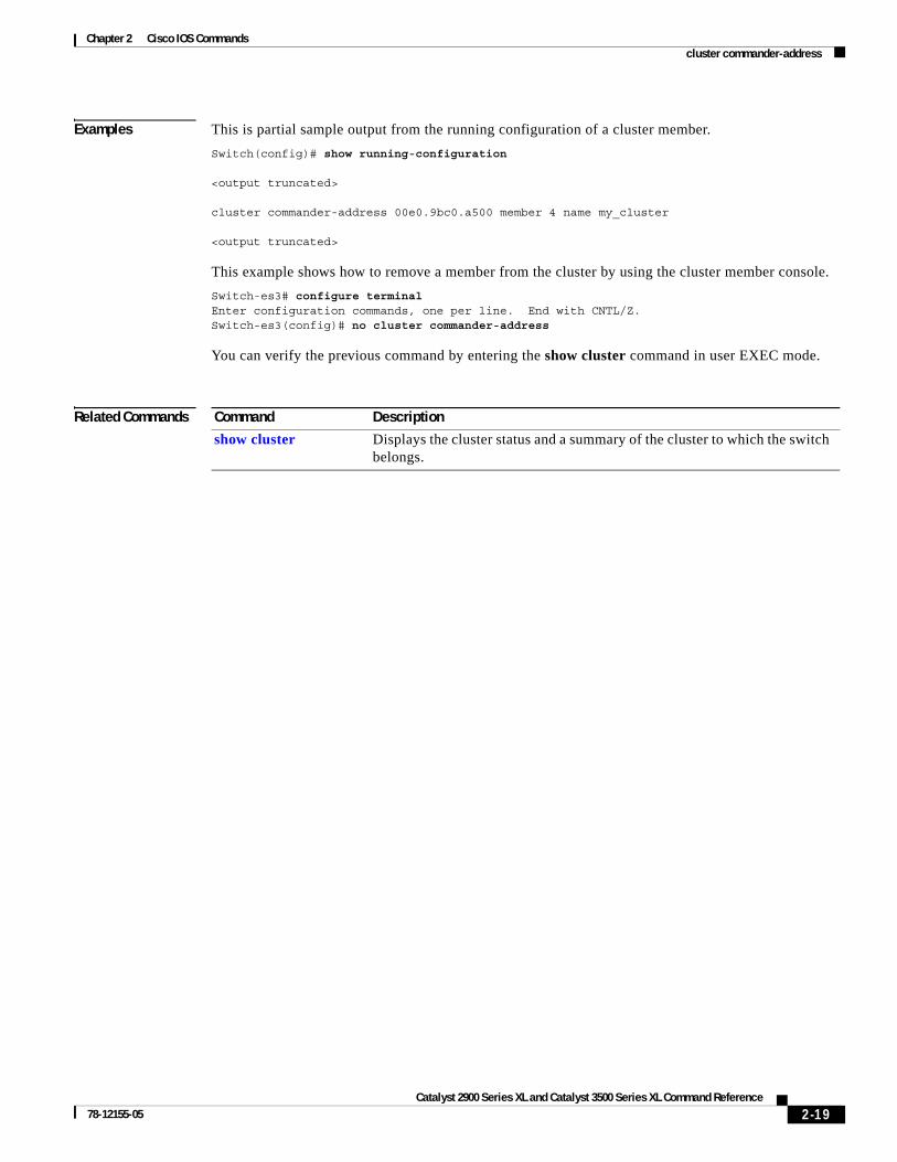
Examples This is partial sample output from the running configuration of a cluster member.
Switch(config)# show running-configuration
<output truncated>
cluster commander-address 00e0.9bc0.a500 member 4 name my_cluster
<output truncated>
This example shows how to remove a member from the cluster by using the cluster member console.
Switch-es3# configure terminalEnter configuration commands, one per line. End with CNTL/Z.Switch-es3(config)# no cluster commander-address
You can verify the previous command by entering the show cluster command in user EXEC mode.
Related Commands Command Description
show cluster Displays the cluster status and a summary of the cluster to which the switch belongs.
2-19Catalyst 2900 Series XL and Catalyst 3500 Series XL Command Reference
78-12155-05

Chapter 2 Cisco IOS Commandscluster discovery hop-count
cluster discovery hop-countUse the cluster discovery hop-count global configuration command on the command switch to set the hop-count limit for extended discovery of candidate switches. Use the no form of this command to set the hop count to the default value.
cluster discovery hop-count number
no cluster discovery hop-count
default cluster discovery hop-count
Syntax Description
Defaults The hop count is set to 3.
Command Modes Global configuration
Command History
Usage Guidelines Enter this command only on the command switch. This command does not operate on member switches.
If the hop count is set to 1, it disables extended discovery. The command switch discovers only candidates that are one hop from the edge of the cluster. The edge of the cluster is the point between the last discovered member switch and the first discovered candidate switch.
Examples This example shows how to set the hop count limit to 4. This command is entered on the command switch.
Switch(config)# cluster discovery hop-count 4
You can verify the previous command by entering the show cluster command in user EXEC mode.
Related Commands
number Number of hops from the cluster edge that the command switch limits the discovery of candidates. The range is from 1 to 7.
no Set the hop count to the default value (3).
default Set the hop count to the default value (3).
Release Modification
12.0(5)XU This command was first introduced.
Command Description
show cluster Displays the cluster status and a summary of the cluster to which the switch belongs.
show cluster candidates Displays a list of candidate switches.
2-20Catalyst 2900 Series XL and Catalyst 3500 Series XL Command Reference
78-12155-05

Chapter 2 Cisco IOS Commandscluster enable
cluster enableUse the cluster enable global configuration command on a command-capable switch to enable it as the cluster command switch, assign a cluster name, and optionally assign a member number to it. Use the no form of the command to remove all members and to make the command switch a candidate switch.
cluster enable name [command-switch-member-number]
no cluster enable
default cluster enable
Syntax Description
Defaults The switch is not a command switch.
No cluster name is defined.
The member number is 0 when this is the command switch.
Command Modes Global configuration
Command History
Usage Guidelines This command runs on any command-capable switch that is not part of any cluster. This command fails if a device is already configured as a member of the cluster.
You must name the cluster when you enable the command switch. If the switch is already configured as the command switch, this command changes the cluster name if it is different from the previous name.
name Name of the cluster up to 31 characters. Valid characters include only alphanumerics, dashes, and underscores.
command-switch-member-number (Optional) Assign a member number to the command switch of the cluster. The range is from 0 to 15.
no Remove all member switches, and make the command switch a candidate.
default Switch is not a command switch.
Release Modification
11.2(8)SA6 This command was first introduced.
12.0(5)XU The command-switch-member-number variable was added.
2-21Catalyst 2900 Series XL and Catalyst 3500 Series XL Command Reference
78-12155-05

Chapter 2 Cisco IOS Commandscluster enable
Examples This example shows how to enable the command switch, to name the cluster, and to set the command switch member number to 4.
Switch(config)# cluster enable Engineering-IDF4 4
You can verify the previous command by entering the show cluster command in user EXEC mode on the command switch.
Related Commands Command Description
show cluster Displays the cluster status and a summary of the cluster to which the switch belongs.
2-22Catalyst 2900 Series XL and Catalyst 3500 Series XL Command Reference
78-12155-05

Chapter 2 Cisco IOS Commandscluster holdtime
cluster holdtimeUse the cluster holdtime global configuration command on the command switch to set the duration in seconds before a switch (either the command or member switch) declares the other switch down after not receiving heartbeat messages. Use the no form of this command to set the duration to the default value.
cluster holdtime holdtime-in-secs
no cluster holdtime
default cluster holdtime
Syntax Description
Defaults The holdtime is 80 seconds.
Command Modes Global configuration
Command History
Usage Guidelines Use this command with the cluster timer global configuration command only on the command switch. The command switch propagates the values to all its cluster members so that the setting is consistent among all switches in the cluster.
The holdtime is typically set as a multiple of the interval timer (cluster timer). For example, it takes (holdtime-in-secs divided by interval-in-secs) number of heartbeat messages to be missed in a row to declare a switch down.
holdtime-in-secs Duration in seconds before a switch (either a command or member switch) declares the other switch down. The range is from 1 to 300 seconds.
no Set the holdtime to the default value (80 seconds).
default Set the holdtime to the default value (80 seconds).
Release Modification
12.0(5)XU This command was first introduced.
2-23Catalyst 2900 Series XL and Catalyst 3500 Series XL Command Reference
78-12155-05

Chapter 2 Cisco IOS Commandscluster holdtime
Examples This example shows how to change the interval timer and the duration on the command switch.
Switch(config)# cluster timer 3Switch(config)# cluster holdtime 30
You can verify the previous commands by entering the show cluster command in user EXEC mode.
Related Commands Command Description
show cluster Displays the cluster status and a summary of the cluster to which the switch belongs.
2-24Catalyst 2900 Series XL and Catalyst 3500 Series XL Command Reference
78-12155-05

Chapter 2 Cisco IOS Commandscluster management-vlan
cluster management-vlanUse the cluster management-vlan global configuration command on the command switch to change the management VLAN for the entire cluster. Use the no form of this command to change the management VLAN to VLAN 1.
cluster management-vlan n
no cluster management-vlan
default cluster management-vlan
Syntax Description
Defaults The default management VLAN is VLAN 1.
Command Modes Global configuration
Command History
Usage Guidelines Enter this command only on the command switch. This command changes the management VLAN of the command switch and member switches. Member switches must have either a trunk connection or connection to the new command-switch management VLAN to maintain communication with the command switch.
This command is not written to the configuration file.
Examples This example shows how to change the management VLAN to VLAN 5 on the entire cluster.
Switch(config)# cluster management-vlan 5
You can verify the previous command by entering the show interface vlan number user EXEC command.
Related Commands
n VLAN ID of the new management VLAN. Valid VLAN IDs are from 1 to 1001.
no Set the management VLAN to VLAN 1.
default Set the management VLAN to VLAN 1.
Release Modification
12.0(5)XU This command was first introduced.
Command Description
management Shuts down the management VLAN interface and enables the new management VLAN interface on an individual switch.
2-25Catalyst 2900 Series XL and Catalyst 3500 Series XL Command Reference
78-12155-05

Chapter 2 Cisco IOS Commandscluster member
cluster memberUse the cluster member global configuration command on the command switch to add members to a cluster. Use the no form of the command to remove members from the cluster.
cluster member [n] mac-address H.H.H [password enable-password]
no cluster member n
default cluster member n
Syntax Description
Defaults A newly enabled command switch has no associated cluster members.
Command Modes Global configuration
Command History
Usage Guidelines Enter this command only on the command switch to add a member to or remove a member from the cluster. If you enter this command on a switch other than the command switch, the switch rejects the command and displays an error message.
You must enter a member number to remove a switch from the cluster. However, you do not need to enter a member number to add a switch to the cluster. The command switch selects the next available member number and assigns it to the switch joining the cluster.
You must enter the enable password of the candidate switch for authentication when it joins the cluster. The password is not saved in the running or startup configuration. After a candidate switch becomes a member of the cluster, its password becomes the same as the command-switch password.
If a switch does not have a configured host name, the command switch appends a member number to the command-switch host name and assigns it to the member switch.
n The number that identifies a cluster member. The range is from 0 to 15.
mac-address H.H.H MAC address of the member switch in hexadecimal format.
password enable-password Enable password of the candidate switch. The password is not required if there is no password on the candidate switch.
no Remove the specified member from the cluster.
default Remove the specified member from the cluster.
Release Modification
11.2(8)SA6 This command was first introduced.
2-26Catalyst 2900 Series XL and Catalyst 3500 Series XL Command Reference
78-12155-05

Chapter 2 Cisco IOS Commandscluster member
Examples This example shows how to add a switch as member 2 with MAC address 00E0.1E00.2222 and the password key to a cluster.
Switch(config)# cluster member 2 mac-address 00E0.1E00.2222 password key
This example shows how to add a switch with MAC address 00E0.1E00.3333 to the cluster. This switch does not have a password. The command switch selects the next available member number and assigns it to the switch joining the cluster.
Switch(config)# cluster member mac-address 00E0.1E00.3333
You can verify the previous command by entering the show cluster members command in user EXEC mode on the command switch.
Related Commands Command Description
show cluster Displays the cluster status and a summary of the cluster to which the switch belongs.
show cluster candidates Displays a list of candidate switches.
show cluster members Displays information about the cluster members.
2-27Catalyst 2900 Series XL and Catalyst 3500 Series XL Command Reference
78-12155-05

Chapter 2 Cisco IOS Commandscluster run
cluster runUse the cluster run global configuration command to enable clustering on a switch. Use the no form of this command to disable clustering on a switch.
cluster run
no cluster run
default cluster run
Syntax Description
Defaults Clustering is enabled on all switches.
Command Modes Global configuration
Command History
Usage Guidelines When you enter the no cluster run command on a command switch, the command switch is disabled. Clustering is disabled, and the switch is incapable of becoming a candidate switch.
When you enter the no cluster run command on a member switch, it is removed from the cluster. Clustering is disabled, and the switch is incapable of becoming a candidate switch.
When you enter the no cluster run command on a switch that is not part of a cluster, clustering is disabled on this switch. This switch cannot then become a candidate switch.
Examples This example shows how to disable clustering on the command switch:
Switch(config)# no cluster run
You can verify the previous command by entering the show cluster command in user EXEC mode.
Related Commands
no Disable clustering on a switch.
default Enable clustering on a switch.
Release Modification
12.0(5)XU This command was first introduced.
Command Description
cluster enable Displays the cluster status and a summary of the cluster to which the switch belongs.
show cluster Displays the cluster status and a summary of the cluster to which the switch belongs.
2-28Catalyst 2900 Series XL and Catalyst 3500 Series XL Command Reference
78-12155-05

Chapter 2 Cisco IOS Commandscluster standby-group
cluster standby-groupUse the cluster standby-group global configuration command to enable command switch redundancy by binding the Hot Standby Router Protocol (HSRP) standby group to the cluster. Use the no form of this command to unbind the cluster from the HSRP standby group.
cluster standby-group HSRP-group-name
no cluster standby-group
default cluster standby-group
Syntax Description
Defaults The cluster is not bound to any HSRP group.
Command Modes Global configuration
Command History
Usage Guidelines You must enter this command only on the command switch. If you enter it on a member switch, an error message appears.
The command switch propagates the cluster-HSRP binding information to all members. Each member switch stores the binding information in its nonvolatile RAM (NVRAM).
The HSRP group name must be a valid standby group; otherwise, the command exits with an error.
HSRP-group-name Name of the HSRP group that is bound to the cluster. The group name is limited to 32 characters.
no Unbind the cluster from the HSRP standby group.
default Unbind the cluster from the HSRP standby group.
Release Modification
12.0(5)XU This command was first introduced.
2-29Catalyst 2900 Series XL and Catalyst 3500 Series XL Command Reference
78-12155-05

Chapter 2 Cisco IOS Commandscluster standby-group
Examples This example shows how to bind the HSRP group named my_hsrp to the cluster. This command is entered on the command switch.
Switch(config)# cluster standby-group my_hsrp
This example shows the error message when this command is entered on a command switch and the specified HSRP standby group does not exist:
Switch(config)# cluster standby-group my_hsrp%ERROR: Standby group (my_hsrp) doesn’t exist
This example shows the error message when this command is entered on a member switch.
Switch(config)# cluster standby-group my_hsrp%ERROR: This command runs on a cluster command switch
You can verify the previous commands by entering the show cluster command in user EXEC mode.
Related Commands Command Description
standby ip Enables HSRP on the interface.
show cluster Displays the cluster status and a summary of the cluster to which the switch belongs.
show standby Displays standby group information.
2-30Catalyst 2900 Series XL and Catalyst 3500 Series XL Command Reference
78-12155-05
Chapter 2 Cisco IOS Commandscluster timer
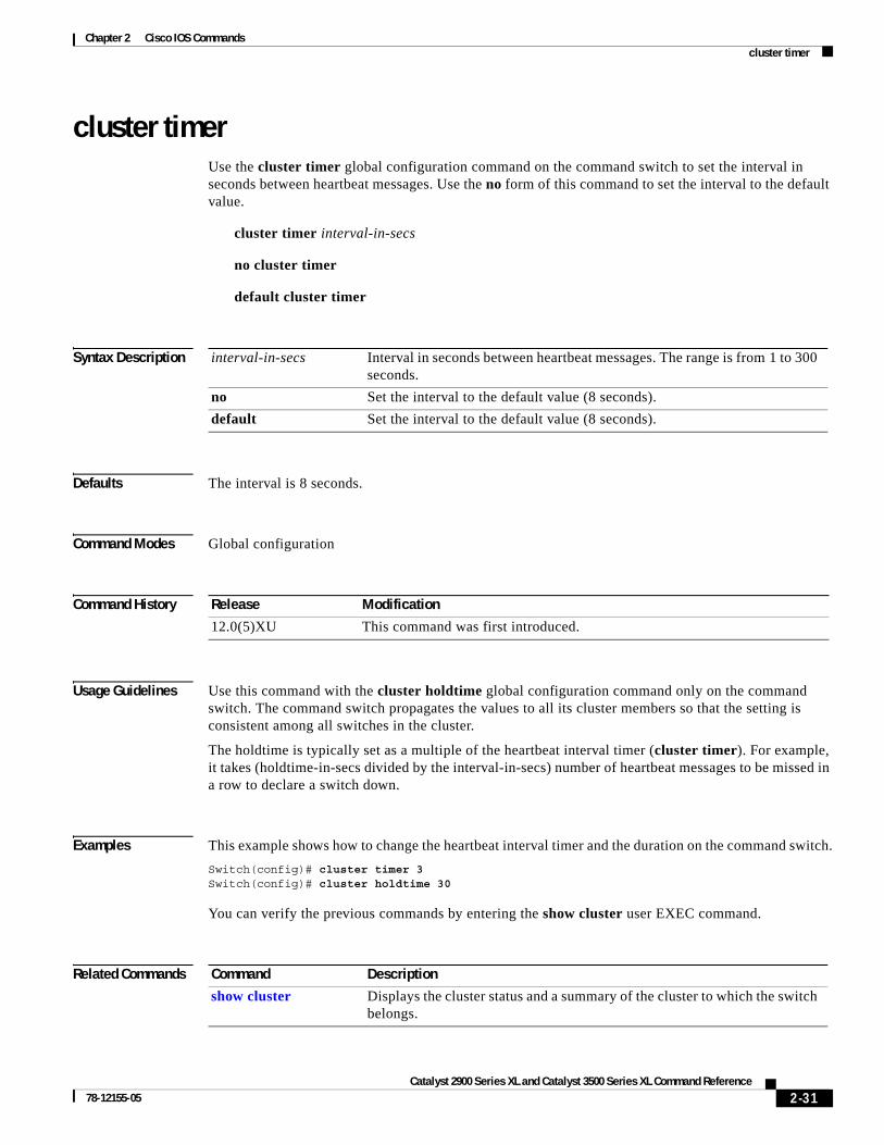
cluster timerUse the cluster timer global configuration command on the command switch to set the interval in seconds between heartbeat messages. Use the no form of this command to set the interval to the default value.
cluster timer interval-in-secs
no cluster timer
default cluster timer
Syntax Description
Defaults The interval is 8 seconds.
Command Modes Global configuration
Command History
Usage Guidelines Use this command with the cluster holdtime global configuration command only on the command switch. The command switch propagates the values to all its cluster members so that the setting is consistent among all switches in the cluster.
The holdtime is typically set as a multiple of the heartbeat interval timer (cluster timer). For example, it takes (holdtime-in-secs divided by the interval-in-secs) number of heartbeat messages to be missed in a row to declare a switch down.
Examples This example shows how to change the heartbeat interval timer and the duration on the command switch.
Switch(config)# cluster timer 3Switch(config)# cluster holdtime 30
You can verify the previous commands by entering the show cluster user EXEC command.
Related Commands
interval-in-secs Interval in seconds between heartbeat messages. The range is from 1 to 300 seconds.
no Set the interval to the default value (8 seconds).
default Set the interval to the default value (8 seconds).
Release Modification
12.0(5)XU This command was first introduced.
Command Description
show cluster Displays the cluster status and a summary of the cluster to which the switch belongs.
2-31Catalyst 2900 Series XL and Catalyst 3500 Series XL Command Reference
78-12155-05

Chapter 2 Cisco IOS Commandscontroller LongReachEthernet
controller LongReachEthernetUse the controller LongReachEthernet global configuration command to enter controller configuration mode.
controller LongReachEthernet ctrlr#
Syntax Description
Defaults There is no default.
Command Modes Global configuration
Command History
Usage Guidelines Use this command to enter controller submode. An LRE controller is the LRE chipset in the switch.
Examples This example shows how to enter controller configuration mode for controller 0.
Switch(config)# controller Lo 0Switch(config-controller)#
Related Commands
ctrlr# The Long-Reach Ethernet (LRE) controller number. Controller numbers are device-specific. Valid entries are 0 to 23 for the Catalyst 2900 LRE XL.
Release Modification
12.0(5)WC6 This command was first introduced.
Command Description
upgrade binary Configures upgrades on either end of an LRE link.
upgrade preserve Prevents an upgrade of the local customer premises equipment (CPE) controller and all remote CPE devices connected to it.
2-32Catalyst 2900 Series XL and Catalyst 3500 Series XL Command Reference
78-12155-05

Chapter 2 Cisco IOS Commandscpe protected
cpe protectedUse the cpe protected interface configuration command to restrict data traffic to individual ports on Cisco 585 LRE customer premises equipment (CPE) ports. Use the no form of this command to allow different ports on the same CPE device to exchange data directly.
cpe protected [port id]
no cpe protected [port id]
Syntax Description
Defaults The default is no cpe protected.
Command Modes Interface configuration
Command History
Usage Guidelines To ensure that data traffic from one CPE port is not accessed on any of the other three ports, use the cpe protected command. The cpe protected command restricts CPE traffic, either at the CPE device level or at the individual port level for data security. By specifying the cpe protected command without a CPE port, data is protected for all applicable CPE ports. By specifying the additional port id parameters, you can protect an indivdual CPE Ethernet port.
When protecting individual CPE ports, always specify a minimum of two ports. A single port that is configured as protected has no effect. Data traffic does not flow between two ports that are protected.
Examples This example show how to protect CPE port 1 on Long-Reach Ethernet 0/1:
Switch# configure terminalSwitch(config)# interface long 0/2Switch(config-if)# cpe protected port 1Switch(config-if)#
Related Commands
port id (Optional) The CPE Ethernet port identifier. Valid values vary from 1 to 4, depending on CPE device.
Release Modification
12.1(11)YJ This command was first introduced.
Command Description
show controllers lre cpe protected
Shows CPE protected port information.
2-33Catalyst 2900 Series XL and Catalyst 3500 Series XL Command Reference
78-12155-05

Chapter 2 Cisco IOS Commandsdebug lre
debug lreUse the debug lre privileged EXEC command to enable debugging of Long-Reach Ethernet (LRE)-related events. Use the no form to disable debugging.
debug lre [controller | errors | profile | state | timing]
no debug lre [controller | profile | state | timing]
Syntax Description
Defaults The default is off.
Command Modes Privileged EXEC
Command History
Usage Guidelines If you use the debug lre command without providing a specific debug option, all LRE debug options are enabled. Conversely, if you use the no debug lre command without providing a specific debug option, all LRE debug options are disabled.
You can enable and disable the LRE debug options on individual ports for the controller, profile, and state debug options. For example, the debug lre state interface-id command debugs the state transition events on a specific port. If a specific port is not provided, the debug option applies to all switch LRE ports.
To troubleshoot LRE connectivity problems, use the debug lre state command to display the state machine transitions and the debug lre errors command to display other information that might explain unusual occurrences that could be affecting connectivity.
controller Display the customer premises equipment (CPE) device Ethernet interface control access and CPE timing information.
errors Display certain types of unexpected events that mean that the switch is configured or operating in a nonstandard way.
profile Display profile management events on the switch.
state Display state transition events of each switch LRE port.
timing Display timing information.
Release Modification
12.0(5)WC1 This command was first introduced.
12.0(5)WC4 This command was extended to support the Cisco 585 LRE CPE device.
12.0(5)WC6 This command was extended to support the display of timing information.
2-34Catalyst 2900 Series XL and Catalyst 3500 Series XL Command Reference
78-12155-05

Chapter 2 Cisco IOS Commandsdebug lre
Examples This example shows how to use the command to enable LRE controller event debugging on all switch LRE ports:
Switch# debug lre controllerLRE Controller Events debugging is on
This is an example of output when the debug lre state option is enabled.
*Mar 1 02:11:39: LRE: Lo0/3: FSM_PROFILE_LINKUP: event:EVT_PORT_CONFIG_CHANGE*Mar 1 02:11:40: LRE: Lo0/3: FSM_PROFILE_APPLIED: event:EVT_LRE_LINK_DOWN*Mar 1 02:11:41: LRE: Lo0/3: FSM_PROFILE_APPLIED: event:EVT_LRE_LINK_UP
This example shows how to disable LRE controller event debugging:
Switch# no debug lre controller
This example shows show to enable debugging with timing information:
Switch# debug lre timing LRE Timing Information debugging is onSwitch#
Related Commands Command Description
show controllers lre status
Displays the LRE link statistics and the profile information on a switch LRE port, including link state, link duration, data rates, power levels, signal-to-noise ratio, and Reed-Solomon errors.
2-35Catalyst 2900 Series XL and Catalyst 3500 Series XL Command Reference
78-12155-05

Chapter 2 Cisco IOS Commandsdelete
deleteUse the delete privileged EXEC command to delete a file from the file system.
delete {device:}filename
Syntax Description
Command Modes Privileged EXEC
Command History
Usage Guidelines A colon (:) follows the device variable. Do not enter spaces after the colon.
Examples This example shows how to delete the file atm_image from the file system for an ATM module installed in slot 1:
Switch# delete slot1:atm_image
This example shows how to delete a file from the switch Flash memory:
Switch# delete flash:filename
You can verify that the file was removed by entering the show flash: user EXEC command.
Related Commands
device: Device containing the file to be deleted. Valid devices include the switch Flash memory and Asynchronous Transfer Mode (ATM) module files. To access the ATM module, specify the slot number (1 or 2).
filename Name of file.
Release Modification
11.2(8)SA6 This command was first introduced.
Command Description
copy tftp Downloads a file from a TFTP server to a device.
2-36Catalyst 2900 Series XL and Catalyst 3500 Series XL Command Reference
78-12155-05

Chapter 2 Cisco IOS Commandsduplex
duplexUse the duplex interface configuration command to specify the duplex mode of operation for Fast Ethernet and Gigabit Ethernet ports. Use the no form of this command to return the port to its default value.
duplex {full | half | auto}
no duplex
Syntax Description
Defaults For 10/100, 100BASE-FX, and Gigabit ports, the default is auto.
Command Modes Interface configuration
Command History
Usage Guidelines Certain ports can be configured as either full duplex or half duplex. Applicability of this command depends on the device to which the switch is attached.
For Fast Ethernet ports, setting the port to auto has the same effect as specifying half if the attached device does not autonegotiate the duplex parameter.
For Gigabit Ethernet ports, setting the port to auto has the same effect as specifying full if the attached device does not autonegotiate the duplex parameter.
If the speed is set to auto, the switch negotiates with the device at the other end of the link for the speed setting and then forces the speed setting to the negotiated value. The duplex setting remains as configured on each end of the link, which could result in a duplex setting mismatch.
If both the speed and duplex are set to specific values, autonegotiation is disabled.
This command is not supported on the ATM module.
For CPE Ethernet ports, the default is half duplex with back pressure. You can change the duplex setting on the Cisco 575 LRE CPE device, but not on the Cisco 585 LRE CPE device. Duplex autonegotiation is supported on the Cisco 575 LRE CPE device, but not on the Cisco 585 LRE CPE device.
Note For guidelines on setting the switch speed and duplex parameters, refer to the Catalyst 2900 Series XL and Catalyst 3500 Series XL Software Configuration Guide.
full Port is in full-duplex mode.
half Port is in half-duplex mode.
auto Port automatically detects whether it should run in full- or half-duplex mode.
Release Modification
11.2(8)SA This command was first introduced.
12.0(5)WC1 This command was extended to support the Cisco 575 LRE CPE device.
12.0(5)WC4 This command was extended to support the Cisco 585 LRE CPE device.
2-37Catalyst 2900 Series XL and Catalyst 3500 Series XL Command Reference
78-12155-05

Chapter 2 Cisco IOS Commandsduplex
Examples This example shows how to set port 1 on a Fast Ethernet module installed in slot 2 to full duplex:
Switch(config)# interface fastethernet2/1Switch(config-if)# duplex full
This example shows how to set port 1 on a Gigabit Ethernet module installed in slot 2 to full duplex:
Switch(config)# interface gigabitethernet2/1Switch(config-if)# duplex full
You can verify the previous commands by entering the show running-config privileged EXEC command.
Related Commands Command Description
show running-config Displays the running configuration on the switch.
speed Specifies the speed of a Fast Ethernet port.
2-38Catalyst 2900 Series XL and Catalyst 3500 Series XL Command Reference
78-12155-05

Chapter 2 Cisco IOS Commandserrdisable detect cause
errdisable detect causeUse the errdisable detect cause global configuration command to enable error disable detection for a UniDirectional Link Detection (UDLD) cause. Use the no form of this command to disable the error disable detection feature.
errdisable detect cause {udld}
no errdisable detect cause {udld}
Syntax Description
Defaults Detection is enabled.
Command Modes Global configuration
Command History
Usage Guidelines A cause (udld) is defined as the reason why the error-disabled state occurred. When a cause is detected on an interface, the interface is placed in error-disabled state, an operational state similar to link-down state.
Use the errdisable recovery global configuration command to set a recovery mechanism for the cause. The switch re-enables the interface and tries the operation again when all causes have timed out. If you do not set a recovery mechanism, you must enter the shutdown and then the no shutdown commands to manually recover an interface from the error-disabled state.
Examples This example shows how to enable error disable detection for the udld error-disable cause:
Switch(config)# errdisable detect cause udld
You can verify your setting by entering the show errdisable detect user EXEC command.
Related Commands
udld Enable error detection on udld.
Release Modification
Release 12.0(5)WC5 This command was first introduced.
Command Description
show errdisable detect Displays errdisable detection information.
2-39Catalyst 2900 Series XL and Catalyst 3500 Series XL Command Reference
78-12155-05

Chapter 2 Cisco IOS Commandserrdisable recovery
errdisable recoveryUse the errdisable recovery global configuration command to configure the recovery mechanism variables. Use the no form of this command to return to the default setting.
errdisable recovery {cause {udld} | {interval interval}
no errdisable recovery {cause {udld} | {interval interval}
Syntax Description
Defaults Recovery is disabled for all causes.
The default recovery interval is 300 seconds.
Command Modes Global configuration
Command History
Usage Guidelines A cause (udld) is defined as the reason why the error-disabled state occurred. When a cause is detected on an interface, the interface is placed in error-disabled state, an operational state similar to link-down state.
Use this command to set a recovery mechanism for the cause. The switch re-enables the interface and tries the operation again when all causes have timed out. If you do not set a recovery mechanism, you must enter the shutdown and then the no shutdown commands to manually recover an interface from the error-disabled state.
cause Enable error disable to recover from a specific cause.
udld Enable the timer to recover from the UniDirectional Link Detection (UDLD) error-disable state.
interval interval Specify the time to recover from the specified error-disable state. The range is 30 to 86400 seconds. The same interval is applied to all causes.
Release Modification
Release 12.0(5)WC5 This command was first introduced.
2-40Catalyst 2900 Series XL and Catalyst 3500 Series XL Command Reference
78-12155-05

Chapter 2 Cisco IOS Commandserrdisable recovery
Examples This example shows how to enable the recovery timer for the udld error-disable cause:
Switch(config)# errdisable recovery cause udld
This example shows how to set the timer to 500 seconds:
Switch(config)# errdisable recovery interval 500
You can verify your settings by entering the show errdisable recovery privileged EXEC command.
Related Commands Command Description
show errdisable recovery Displays errdisable recovery timer information.
2-41Catalyst 2900 Series XL and Catalyst 3500 Series XL Command Reference
78-12155-05

Chapter 2 Cisco IOS Commandsexit
exitUse the exit VLAN database command to implement the proposed VLAN database, to increment the database configuration number, to propagate it throughout the administrative domain, and to return to privileged EXEC mode.
exit
Syntax Description This command has no arguments or keywords.
Defaults No default is defined.
Command Modes VLAN database
Command History
Usage Guidelines The exit command implements all the configuration changes that you made since you entered VLAN database mode and uses them for the running configuration. This command returns you to privileged EXEC mode.
Examples This example shows how to implement the proposed VLAN database and to exit to privileged EXEC mode:
Switch(vlan)# exitSwitch#
You can verify the previous command by entering the show vlan brief user EXEC command.
Release Modification
11.2(8)SA4 This command was first introduced.
2-42Catalyst 2900 Series XL and Catalyst 3500 Series XL Command Reference
78-12155-05

Chapter 2 Cisco IOS Commandsexit
Related Commands Command Description
abort Abandons the proposed VLAN database, exits VLAN database mode, and returns to privileged EXEC mode.
apply Implements the proposed VLAN database, increments the database configuration revision number, propagates it throughout the administrative domain, and remains in VLAN database mode.
reset Abandons the proposed VLAN database and remains in VLAN database mode. Resets the proposed database to the currently implemented VLAN database on the switch.
show vlan Displays the parameters for all configured VLANs in the administrative domain.
shutdown vlan Shuts down (suspends) local traffic on the specified VLAN.
vlan database Enters VLAN database mode from the command-line interface (CLI).
2-43Catalyst 2900 Series XL and Catalyst 3500 Series XL Command Reference
78-12155-05

Chapter 2 Cisco IOS Commandsflowcontrol
flowcontrolUse the flowcontrol interface configuration command on Gigabit Ethernet ports to control traffic rates during congestion. Use the no form of this command to disable flow control on the port.
flowcontrol {asymmetric | symmetric}
no flowcontrol
Syntax Description
Defaults The default is asymmetric.
Command Modes Interface configuration
Command History
Examples This example shows how to configure the local port to support any level of flow control by the remote port:
Switch(config-if)# flowcontrol
This example shows how to configure the local port to control the traffic flow from the remote port:
Switch(config-if)# flowcontrol asymmetric
You can verify the previous commands by entering the show running-config privileged EXEC command.
Related Commands
asymmetric Enable the local port to perform flow control of the remote port. If the local port is congested, it can request the remote port to stop transmitting. The local port requests that the remote port begin transmitting after the congestion clears.
symmetric Enable the local port to perform flow control only if the remote port can also perform flow control of the local port. If the remote port cannot perform flow control, the local port also does not.
Release Modification
11.2(8)SA6 This command was first introduced.
Command Description
show interface [interface-id] flow-control
Displays flow-control information for the specified port.
2-44Catalyst 2900 Series XL and Catalyst 3500 Series XL Command Reference
78-12155-05

Chapter 2 Cisco IOS Commandshw-module slot module-slot # upgrade lre
hw-module slot module-slot # upgrade lreUse the hw-module slot module-slot # lre upgrade lre privileged EXEC command to perform firmware upgrades on Long-Reach Ethernet (LRE) systems.
hw-module slot module-slot # upgrade lre [force] [{local ctrlr unit # | remote interface-id}]
Syntax Description
Defaults No default is defined.
Command Modes Privileged EXEC
Command History
Usage Guidelines Use the hw-module slot module-slot # upgrade lre command to start an LRE upgrade these ways:
• Upgrade all LRE local chipsets (controllers) and remote CPE devices by entering the hw-module slot module-slot # upgrade lre command with no additional parameters.
• Upgrade a single local LRE controller by entering the hw-module slot module-slot # lre upgrade command with the local parameter.
• Upgrade a single remote LRE CPE device by entering the hw-module slot module-slot # lre upgrade command with the remote parameter.
The force option allows users to upgrade an LRE binary on a local LRE controller or a remote LRE CPE device even though the device is already running the version of the desired LRE binary. The default behavior is not to upgrade LRE binaries that are already up-to-date.
During an upgrade, users on the LRE links being upgraded experience a temporary disruption of Ethernet connectivity. All LRE local and remote upgrades run concurrently and take 3 to 6 minutes to complete.
The IOS CLI remains available while an LRE upgrade is in progress.
Once started, an LRE upgrade can only be stopped by physically changing the remote CPE device or by reloading the IOS software on the Ethernet switch.
module-slot # Physical slot that connects the local (LRE switch) and remote (customer premises equipment [CPE] device) ends of the upgrade.
force (Optional) LRE binaries upgrade, even when the version of the LRE binary on the switch Flash memory and the LRE binary currently in use are the same.
local ctrlr unit # (Optional) The single LRE chipset for a controller at the local end of the LRE link.
remote interface-id (Optional) One or more chipsets on a single CPE device at the remote end of the LRE link.
Release Modification
12.0(5)WC6 This command was first introduced.
2-45Catalyst 2900 Series XL and Catalyst 3500 Series XL Command Reference
78-12155-05

Chapter 2 Cisco IOS Commandshw-module slot module-slot # upgrade lre
Under most circumstances, configuration for upgrades is not necessary.
Examples This example shows how to start a system-wide LRE upgrade:
Switch# hw-module slot 0 upgrade lre
You are about to start an LRE upgrade on all LRE interfaces.Users on LRE links being upgraded will experience a temporarydisruption of Ethernet connectivity.
Start LRE upgrade ? [yes]:
Starting remote upgrade on CPE Lo0/1.Starting remote upgrade on CPE Lo0/2Starting remote upgrade on CPE Lo0/3Starting remote upgrade on CPE Lo0/4Starting remote upgrade on CPE Lo0/5Starting remote upgrade on CPE Lo0/6Starting remote upgrade on CPE Lo0/7Starting remote upgrade on CPE Lo0/8Starting upgrade on local controller LongReachEthernet 0Starting remote upgrade on CPE Lo0/9Starting remote upgrade on CPE Lo0/10Starting remote upgrade on CPE Lo0/11Starting remote upgrade on CPE Lo0/12Starting remote upgrade on CPE Lo0/13Starting remote upgrade on CPE Lo0/14Starting remote upgrade on CPE Lo0/15Starting remote upgrade on CPE Lo0/16Starting upgrade on local controller LongReachEthernet 1Starting remote upgrade on CPE Lo0/17Starting remote upgrade on CPE Lo0/18Starting remote upgrade on CPE Lo0/19Starting remote upgrade on CPE Lo0/20Starting remote upgrade on CPE Lo0/21Starting remote upgrade on CPE Lo0/22Starting remote upgrade on CPE Lo0/23Starting remote upgrade on CPE Lo0/24Starting upgrade on local controller LongReachEthernet 2
This example shows how to start an LRE upgrade on a single LRE controller in a switch. In this example, LongRangeEthernet 0 causes an LRE upgrade on controller 0 in the switch.
Switch# hw-module slot 0 upgrade lre local lo 0You are about to start an LRE upgrade on local controller LongReachEthernet 0.Users on LRE links being upgraded will experience a temporarydisruption of Ethernet connectivity.
Start LRE upgrade ? [yes]:
Starting Upgrade on local controller LongReachEthernet 0
This example shows how to start an LRE upgrade on a single CPE device. In this example, LongRangeEthernet 0/1 causes an LRE upgrade to run on the CPE device connected to LRE link LongRangeEthernet 0/1.
Switch# hw-module slot 0 upgrade lre remote lo 0/1
You are about to start an LRE upgrade on CPE Lo0/1.Users on LRE links being upgraded will experience a temporarydisruption of Ethernet connectivity.
2-46Catalyst 2900 Series XL and Catalyst 3500 Series XL Command Reference
78-12155-05

Chapter 2 Cisco IOS Commandshw-module slot module-slot # upgrade lre
Start LRE upgrade ? [yes]:
Starting remote upgrade on CPE Lo0/1
This example shows what happens when you attempt to upgrade firmware without using the force option.
Switch# hw-module slot 0 upgrade lre remote lo 0/1
You are about to start an LRE upgrade on CPE Lo0/1.Users on LRE links being upgraded will experience a temporarydisruption of Ethernet connectivity.
Start LRE upgrade ? [yes]:
No upgrade required on CPE Lo0/1
This example shows the output when you attempt to upgrade current firmware on a CPE device by using the force option:
Switch# hw-module slot 0 upgrade lre force remote lo 0/1
You are about to start an LRE upgrade on CPE Lo0/1.Users on LRE links being upgraded will experience a temporarydisruption of Ethernet connectivity.
Start LRE upgrade ? [yes]:
Starting remote upgrade on CPE Lo0/1Switch#
Related Commands Command Description
controller LongReachEthernet Entry for controller submode.
show lre upgrade binaries Displays the LRE binaries present on the system Flash memory.
show lre upgrade status Displays the upgrade status on all ports in the switch.
show lre upgrade version Displays the version of binaries on local and remote ends of an LRE link.
2-47Catalyst 2900 Series XL and Catalyst 3500 Series XL Command Reference
78-12155-05

Chapter 2 Cisco IOS Commandsinterface
interfaceUse the interface global configuration command to configure an interface type, to create a switch virtual interface to be used as the management VLAN interface, and to enter interface configuration mode.
interface type slot/port | vlan number
no interface type slot/port | vlan number
Syntax Description
Defaults The default management VLAN interface is VLAN 1.
Command Modes Global configuration
Command History
Usage Guidelines When creating a management VLAN interface, a space between vlan and number is accepted.
Only one management VLAN interface can be active.
You cannot delete the management VLAN 1 interface.
Before bringing up a new management VLAN interface with the no shutdown command, you must enter the shutdown command to disable the old one.
You can use the management command to shut down the active management VLAN interface and to enable the newly created management VLAN interface.
You can configure the management VLAN interface on static-access, multi-VLAN, dynamic-access, and trunk ports.
type Type of interface to be configured. Can be Fast Ethernet, Gigabit Ethernet, or Asynchronous Transfer Mode (ATM).
slot Slot number (0, 1, or 2). For an ATM module, use slot number 1 or 2.
port Port ID.
vlan number VLAN number from 1 to 1001 to be used as the management VLAN. Do not enter leading zeros.
Release Modification
11.2(8)SA This command was first introduced.
11.2(8)SA3 The vlan keyword was added.
2-48Catalyst 2900 Series XL and Catalyst 3500 Series XL Command Reference
78-12155-05
Chapter 2 Cisco IOS Commandsinterface
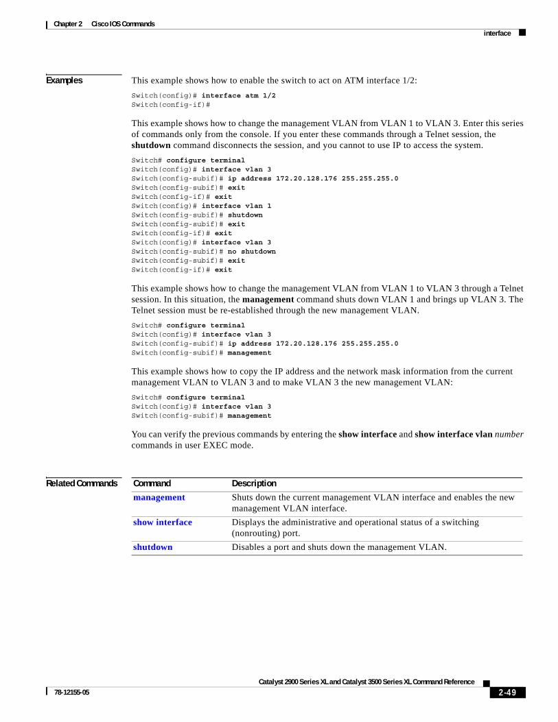
Examples This example shows how to enable the switch to act on ATM interface 1/2:
Switch(config)# interface atm 1/2Switch(config-if)#
This example shows how to change the management VLAN from VLAN 1 to VLAN 3. Enter this series of commands only from the console. If you enter these commands through a Telnet session, the shutdown command disconnects the session, and you cannot to use IP to access the system.
Switch# configure terminalSwitch(config)# interface vlan 3Switch(config-subif)# ip address 172.20.128.176 255.255.255.0Switch(config-subif)# exitSwitch(config-if)# exitSwitch(config)# interface vlan 1Switch(config-subif)# shutdownSwitch(config-subif)# exitSwitch(config-if)# exitSwitch(config)# interface vlan 3Switch(config-subif)# no shutdownSwitch(config-subif)# exitSwitch(config-if)# exit
This example shows how to change the management VLAN from VLAN 1 to VLAN 3 through a Telnet session. In this situation, the management command shuts down VLAN 1 and brings up VLAN 3. The Telnet session must be re-established through the new management VLAN.
Switch# configure terminalSwitch(config)# interface vlan 3Switch(config-subif)# ip address 172.20.128.176 255.255.255.0Switch(config-subif)# management
This example shows how to copy the IP address and the network mask information from the current management VLAN to VLAN 3 and to make VLAN 3 the new management VLAN:
Switch# configure terminalSwitch(config)# interface vlan 3Switch(config-subif)# management
You can verify the previous commands by entering the show interface and show interface vlan number commands in user EXEC mode.
Related Commands Command Description
management Shuts down the current management VLAN interface and enables the new management VLAN interface.
show interface Displays the administrative and operational status of a switching (nonrouting) port.
shutdown Disables a port and shuts down the management VLAN.
2-49Catalyst 2900 Series XL and Catalyst 3500 Series XL Command Reference
78-12155-05

Chapter 2 Cisco IOS Commandsip address
ip addressUse the ip address interface configuration command to set an IP address for a switch. Use the no form of this command to remove an IP address or to disable IP processing.
ip address ip-address subnet-mask
no ip address ip-address subnet-mask
Syntax Description
Defaults No IP address is defined for the switch.
Command Modes Interface configuration
Command History
Usage Guidelines A switch can have one IP address.
The IP address of the switch can be accessed only by nodes connected to ports that belong to the management VLAN. By default, the management VLAN is VLAN 1, but you can configure a different VLAN as the management VLAN.
If you remove the IP address through a Telnet session, your connection to the switch will be lost.
If your switch receives its IP address from a Bootstrap Protocol (BOOTP) or Dynamic Host Configuration Protocol (DHCP) server and you remove the switch IP address by using the no ip address command, IP processing is disabled, and the BOOTP or DHCP server cannot reassign the address.
Examples This example shows how to configure the IP address for the switch on a subnetted network:
Switch(config)# interface vlan 1Switch(config-if)# ip address 172.20.128.2 255.255.255.0
You can verify the previous commands by entering the show running-config privileged EXEC command.
Related Commands
ip-address IP address.
subnet-mask Mask for the associated IP subnet.
Release Modification
11.2(8)SA This command was first introduced.
Command Description
show running-config Displays the running configuration on the switch.
clear mac-address-table Deletes an IP address for a switch without disabling the IP processing.
2-50Catalyst 2900 Series XL and Catalyst 3500 Series XL Command Reference
78-12155-05

Chapter 2 Cisco IOS Commandsip igmp filter
ip igmp filterUse the ip igmp filter interface configuration command to apply an Internet Group Management Protocol (IGMP) profile to an interface and to prevent hosts on an interface from joining one or more IP multicast groups. Use the no form of this command to remove a specified profile from an interface.
ip igmp filter profile number
no ip igmp filter profile number
Syntax Description
Defaults No IGMP filtering profiles are assigned to an interface.
Command Modes Interface configuration
Command History
Usage Guidelines The same IGMP profile can be applied to more than one switch port interface.
Examples This example shows how to apply an IGMP filtering profile to an interface:
Switch(config-if)# ip igmp filter 30
You can verify your settings by entering the show ip igmp profile profile number user EXEC command.
Related Commands
profile number The range is from 1 to 4294967295.
Release Modification
12.0(5)WC3 This command was first introduced.
Command Description
ip igmp profile Defines a new IGMP filtering profile.
show ip igmp profile Displays the details of an IGMP filtering profile entry.
show running-config interface interface name Displays the running configuration on the switch, including any profiles assigned to a port.
2-51Catalyst 2900 Series XL and Catalyst 3500 Series XL Command Reference
78-12155-05

Chapter 2 Cisco IOS Commandsip igmp max-groups
ip igmp max-groupsUse the ip igmp max-groups interface configuration command to specify the maximum number of Internet Group Management Protocol (IGMP) groups that can be active on a port.
ip igmp max-groups number
Syntax Description
Defaults No maximum number of IGMP groups are defined.
Command Modes Interface configuration
Command History
Usage Guidelines There is no limit to the number of multicast groups that a port can join.
If 0 is specified as the maxgroups value for an interface, that interface cannot join any multicast groups.
Examples This example shows how to limit the number of IGMP groups that an interface can join to 25.Switch(config)# interface fastethernet 0/12Switch(config-if)# ip igmp max-groups 25
You can verify your setting by using the show running-configuration privileged EXEC command and by specifying an interface.
Switch# show running-config interface fastethernet 0/12Building configuration...
Current configuration :124 bytes!interface FastEthernet0/12 no ip address shutdown snmp trap link-status ip igmp max-groups 25 ip igmp filter 22end
You can verify your settings by entering the show running-config interface interface configuration command.
number The maximum number of IGMP filtering groups that can be active on a port. The range is from 0 to 256.
Release Modification
12.0(5)WC3 This command was first introduced.
2-52Catalyst 2900 Series XL and Catalyst 3500 Series XL Command Reference
78-12155-05

Chapter 2 Cisco IOS Commandsip igmp max-groups
Related Commands Command Description
ip igmp profile Applies an IGMP filtering profile to an interface.
show ip igmp profile Displays the details of an IGMP filtering profile entry.
2-53Catalyst 2900 Series XL and Catalyst 3500 Series XL Command Reference
78-12155-05
Chapter 2 Cisco IOS Commandsip igmp profile
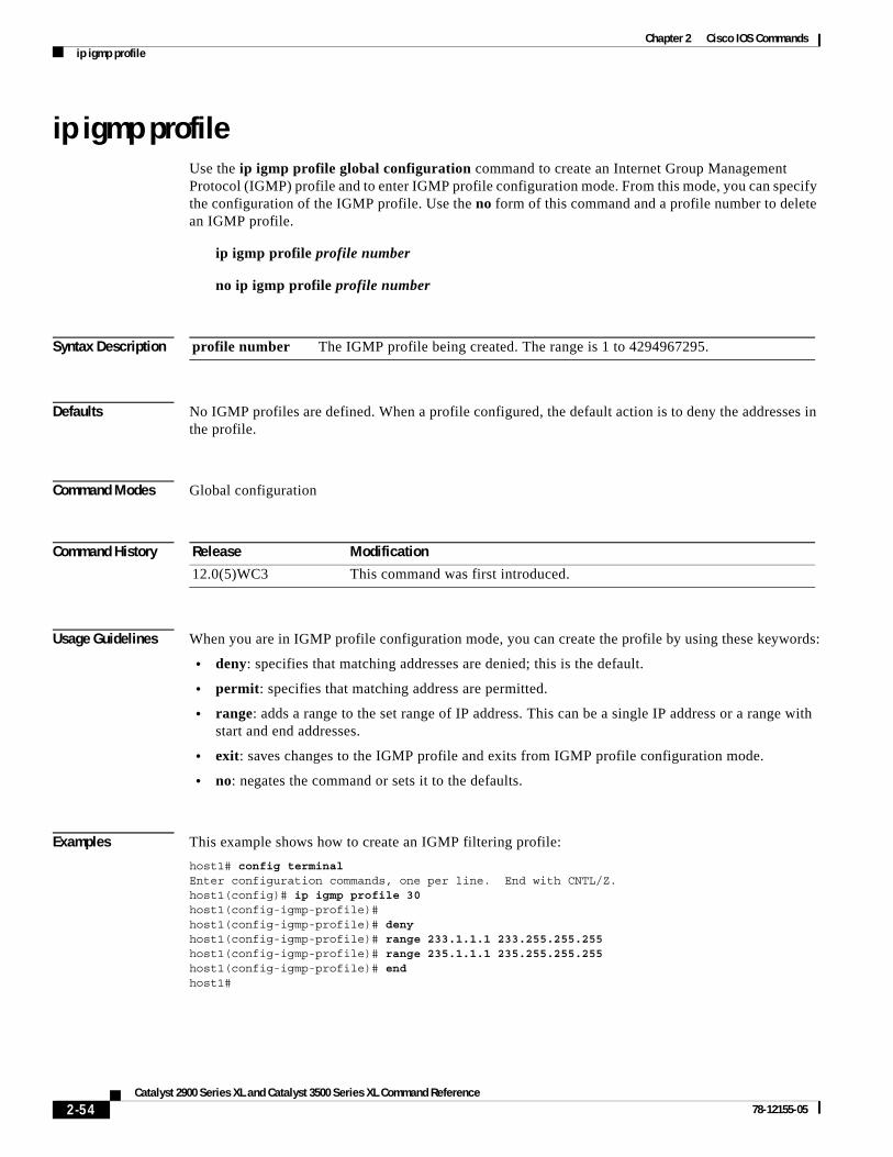
ip igmp profileUse the ip igmp profile global configuration command to create an Internet Group Management Protocol (IGMP) profile and to enter IGMP profile configuration mode. From this mode, you can specify the configuration of the IGMP profile. Use the no form of this command and a profile number to delete an IGMP profile.
ip igmp profile profile number
no ip igmp profile profile number
Syntax Description
Defaults No IGMP profiles are defined. When a profile configured, the default action is to deny the addresses in the profile.
Command Modes Global configuration
Command History
Usage Guidelines When you are in IGMP profile configuration mode, you can create the profile by using these keywords:
• deny: specifies that matching addresses are denied; this is the default.
• permit: specifies that matching address are permitted.
• range: adds a range to the set range of IP address. This can be a single IP address or a range with start and end addresses.
• exit: saves changes to the IGMP profile and exits from IGMP profile configuration mode.
• no: negates the command or sets it to the defaults.
Examples This example shows how to create an IGMP filtering profile:
host1# config terminalEnter configuration commands, one per line. End with CNTL/Z.host1(config)# ip igmp profile 30host1(config-igmp-profile)# host1(config-igmp-profile)# deny host1(config-igmp-profile)# range 233.1.1.1 233.255.255.255 host1(config-igmp-profile)# range 235.1.1.1 235.255.255.255 host1(config-igmp-profile)# end host1#
profile number The IGMP profile being created. The range is 1 to 4294967295.
Release Modification
12.0(5)WC3 This command was first introduced.
2-54Catalyst 2900 Series XL and Catalyst 3500 Series XL Command Reference
78-12155-05

Chapter 2 Cisco IOS Commandsip igmp profile
Related Commands Command Description
ip igmp profile Applies an IGMP filtering profile to an interface.
show ip igmp profile Displays the details of an IGMP filtering profile entry.
show running-config interface Displays the running configuration on the switch, including any profiles assigned to a port.
2-55Catalyst 2900 Series XL and Catalyst 3500 Series XL Command Reference
78-12155-05
Chapter 2 Cisco IOS Commandslogin authentication
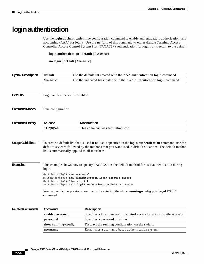
login authenticationUse the login authentication line configuration command to enable authentication, authorization, and accounting (AAA) for logins. Use the no form of this command to either disable Terminal Access Controller Access Control System Plus (TACACS+) authentication for logins or to return to the default.
login authentication {default | list-name}
no login {default | list-name}
Syntax Description
Defaults Login authentication is disabled.
Command Modes Line configuration
Command History
Usage Guidelines To create a default list that is used if no list is specified in the login authentication command, use the default keyword followed by the methods that you want used in default situations. The default method list is automatically applied to all interfaces.
Examples This example shows how to specify TACACS+ as the default method for user authentication during login:
Switch(config)# aaa new-modelSwitch(config)# aaa authentication login default tacacsSwitch(config)# line vty 0 4Switch(config-line)# login authentication default tacacs
You can verify the previous commands by entering the show running-config privileged EXEC command.
Related Commands
default Use the default list created with the AAA authentication login command.
list-name Use the indicated list created with the AAA authentication login command.
Release Modification
11.2(8)SA6 This command was first introduced.
Command Description
enable password Specifies a local password to control access to various privilege levels.
password Specifies a password on a line.
show running-config Displays the running configuration on the switch.
username Establishes a username-based authentication system.
2-56Catalyst 2900 Series XL and Catalyst 3500 Series XL Command Reference
78-12155-05

Chapter 2 Cisco IOS Commandslre log
lre logUse the lre log interface configuration command to specify the mode in which LRE events are logged. Use the no form of the command to turn off logging of events.
lre log {disable | event | extended | normal | maximum}
no lre log {disable | event | extended | normal | maximum}
Syntax Description
Defaults The default is normal.
Command Modes Interface configuration
Command History
Usage Guidelines This command is not needed for nominal operation of the switch. However, it can be used as a diagnostic tool to analyze activity on the switch.
The maximum number of events that can be logged on a per-port basis is 50. Eventually, the log overwrites itself when full.
Examples This example of the lre log command shows how to disable the log:
Switch (config)# interface lo0/1Switch(config-if)# lre log disableSwitch (config-if)#
This example of the lre log command shows how to set logging for state machines:
Switch (config)# interface lo0/1Switch(config-if)# lre log eventSwitch (config-if)#
This example of the lre log command shows how to extend event logging to include all possible parameters:
Switch (config)# interface lo0/1Switch(config-if)# lre log extendedSwitch (config-if)#
disable Disable logging for this port.
event Log events only.
extended Log events and all possible parameters.
normal Log events and some typical parameters.
maximum Set event log maximum buffer size.
Release Modification
12.0(5)WC6 This command was first introduced.
2-57Catalyst 2900 Series XL and Catalyst 3500 Series XL Command Reference
78-12155-05

Chapter 2 Cisco IOS Commandslre log
This example of the lre log command shows how to add some typical parameters to logging events for state machines:
Switch (config)# interface lo0/1Switch(config-if)# lre log normal Switch (config-if)#
This example of the lre log command shows how to not allow logging to be disabled:
Switch (config)# interface lo0/1Switch(config-if)# no lre logSwitch (config-if)#
Related Commands Command Description
clear controllers lre log Deletes the history of link, configuration, and timer events for a specific LRE port or for all switch LRE ports.
show controllers lre log Displays the history of link, configuration, and timer events for a specific LRE port or all switch LRE ports.
2-58Catalyst 2900 Series XL and Catalyst 3500 Series XL Command Reference
78-12155-05
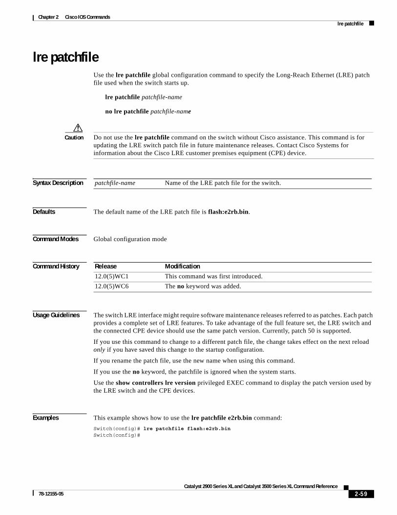
Chapter 2 Cisco IOS Commandslre patchfile
lre patchfileUse the lre patchfile global configuration command to specify the Long-Reach Ethernet (LRE) patch file used when the switch starts up.
lre patchfile patchfile-name
no lre patchfile patchfile-name
Caution Do not use the lre patchfile command on the switch without Cisco assistance. This command is for updating the LRE switch patch file in future maintenance releases. Contact Cisco Systems for information about the Cisco LRE customer premises equipment (CPE) device.
Syntax Description
Defaults The default name of the LRE patch file is flash:e2rb.bin.
Command Modes Global configuration mode
Command History
Usage Guidelines The switch LRE interface might require software maintenance releases referred to as patches. Each patch provides a complete set of LRE features. To take advantage of the full feature set, the LRE switch and the connected CPE device should use the same patch version. Currently, patch 50 is supported.
If you use this command to change to a different patch file, the change takes effect on the next reload only if you have saved this change to the startup configuration.
If you rename the patch file, use the new name when using this command.
If you use the no keyword, the patchfile is ignored when the system starts.
Use the show controllers lre version privileged EXEC command to display the patch version used by the LRE switch and the CPE devices.
Examples This example shows how to use the lre patchfile e2rb.bin command:
Switch(config)# lre patchfile flash:e2rb.binSwitch(config)#
patchfile-name Name of the LRE patch file for the switch.
Release Modification
12.0(5)WC1 This command was first introduced.
12.0(5)WC6 The no keyword was added.
2-59Catalyst 2900 Series XL and Catalyst 3500 Series XL Command Reference
78-12155-05

Chapter 2 Cisco IOS Commandslre patchfile
Related Commands Command Description
show controllers lre version Displays the version number of the hardware, software, and patch software components of the switch LRE interface and the CPE LRE interface.
debug lre Enable debugging of LRE-related events.
2-60Catalyst 2900 Series XL and Catalyst 3500 Series XL Command Reference
78-12155-05

Chapter 2 Cisco IOS Commandslre persistence
lre persistenceUse the lre persistence interface configuration command to set the amount of delay before the link reports a link failure. Use the no form of the command to return to the default settting.
lre persistence delay
no lre persistence delay
Syntax Description
Defaults The default is 3 seconds.
Command Modes Interface configuration mode
Command History
Usage Guidelines Enter the lre persistence command before the link enters the profile link-up mode. If the link is already in the profile link-up mode when you enter the persistence value, the new value does not go into effect immediately. Instead, it becomes effective after the profile link goes down and then comes back up again.
Examples: This example of the lre persistence command establishes a 1-second delay before the link reports a failure:
Switch(config)# interface lo0/1Switch(config-if)# lre persistence 1Switch(config-if)#
Related Commands
delay The amount of time delay; valid values can be 1 to 20 seconds.
Release Modification
12.0(5) WC6 This command was first introduced.
Command Description
show controllers lre status Displays the status of persistence.
2-61Catalyst 2900 Series XL and Catalyst 3500 Series XL Command Reference
78-12155-05
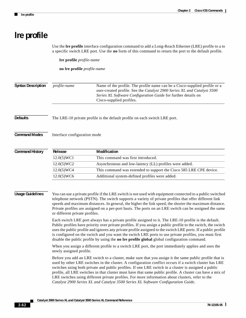
Chapter 2 Cisco IOS Commandslre profile
lre profileUse the lre profile interface configuration command to add a Long-Reach Ethernet (LRE) profile to a to a specific switch LRE port. Use the no form of this command to return the port to the default profile.
lre profile profile-name
no lre profile profile-name
Syntax Description
Defaults The LRE-10 private profile is the default profile on each switch LRE port.
Command Modes Interface configuration mode
Command History
Usage Guidelines You can use a private profile if the LRE switch is not used with equipment connected to a public switched telephone network (PSTN). The switch supports a variety of private profiles that offer different link speeds and maximum distances. In general, the higher the link speed, the shorter the maximum distance. Private profiles are assigned on a per-port basis. The ports on an LRE switch can be assigned the same or different private profiles.
Each switch LRE port always has a private profile assigned to it. The LRE-10 profile is the default. Public profiles have priority over private profiles. If you assign a public profile to the switch, the switch uses the public profile and ignores any private profile assigned to the switch LRE ports. If a public profile is configured on the switch and you want the switch LRE ports to use private profiles, you must first disable the public profile by using the no lre profile global global configuration command.
When you assign a different profile to a switch LRE port, the port immediately applies and uses the newly assigned profile.
Before you add an LRE switch to a cluster, make sure that you assign it the same public profile that is used by other LRE switches in the cluster. A configuration conflict occurs if a switch cluster has LRE switches using both private and public profiles. If one LRE switch in a cluster is assigned a public profile, all LRE switches in that cluster must have that same public profile. A cluster can have a mix of LRE switches using different private profiles. For more information about clusters, refer to the Catalyst 2900 Series XL and Catalyst 3500 Series XL Software Configuration Guide.
profile-name Name of the profile. The profile name can be a Cisco-supplied profile or a user-created profile. See the Catalyst 2900 Series XL and Catalyst 3500 Series XL Software Configuration Guide for further details on Cisco-supplied profiles.
Release Modification
12.0(5)WC1 This command was first introduced.
12.0(5)WC2 Asynchronous and low-latency (LL) profiles were added.
12.0(5)WC4 This command was extended to support the Cisco 585 LRE CPE device.
12.0(5)WC6 Additional system-defined profiles were added.
2-62Catalyst 2900 Series XL and Catalyst 3500 Series XL Command Reference
78-12155-05

Chapter 2 Cisco IOS Commandslre profile
For a complete list of considerations for using LRE profiles, refer to the “LRE Links and LRE Profiles” section in the Catalyst 2900 Series XL and Catalyst 3500 Series XL Software Configuration Guide.
Examples This example shows how to assign the LRE-4 private profile to the switch LRE port 1:
Switch(config)# interface lo0/1Switch(config-if)# lre profile LRE-15Switch(config-if)#
Related Commands Command Description
lre profile global Assigns a public profile to all switch LRE ports.
show controllers lre profile names
Displays information about the LRE profiles available on the switch.
show controllers lre profile details
Displays information about how the LRE profiles are assigned to the switch LRE ports.
2-63Catalyst 2900 Series XL and Catalyst 3500 Series XL Command Reference
78-12155-05

Chapter 2 Cisco IOS Commandslre profile global
lre profile globalUse the lre profile global global configuration command to assign a Long-Reach Ethernet (LRE) public profile to all switch LRE ports.
lre profile global profile-name
no lre profile global
Syntax Description
Defaults No default is defined.
Command Modes Global configuration mode
Command History
Usage Guidelines We strongly recommend using a public profile if the switch is used with equipment directly connected to a public switched telephone network (PSTN) without a private branch exchange (PBX) between the LRE switch and the public telephone lines. When the switch is configured with a public profile, all LRE ports use the same configuration to prevent the switch from causing interference with the other lines on the PSTN.
Note Consult the regulations for connecting to the PSTN in your area.
Note Cisco LRE products can share lines with analog, Integrated Services Digital Network (ISDN), and digital private branch exchange (PBX) switch telephones that use the 0 to 700 kHz frequency range. Digital telephones connected to digital PBX switches that use frequencies above 700 kHz do not work when sharing a line with LRE signals. Due to the proprietary nature of PBX switches, some digital PBX switch services use frequencies above 700 kHz.
The standards for spectral profiles have not yet been ratified. The PUBLIC-ANSI profile corresponds to ANSI Plan 998. The PUBLIC-ETSI profile corresponds to ETSI Plan 997. Both plans are draft standards. ANSI and ETSI requirements can vary. The PUBLIC-ANSI and PUBLIC-ETSI profiles are not meant to apply to all conditions. Contact Cisco Systems for the latest information about standards ratification or for updates to the public profiles.
profile-name Name of the public profile, either PUBLIC-ANSI or PUBLIC-ETSI.
Release Modification
12.0(5)WC1 This command was first introduced.
12.0(5)WC4 This command was extended to support the Cisco 585 LRE CPE device
2-64Catalyst 2900 Series XL and Catalyst 3500 Series XL Command Reference
78-12155-05

Chapter 2 Cisco IOS Commandslre profile global
Each switch LRE port always has a private profile assigned to it. The LRE-10 profile is the default. Public profiles have priority over private profiles. If you assign a public profile to the switch, the switch uses the public profile and ignores any private profile assigned to the switch LRE ports. If a public profile is configured on the switch and you want the switch LRE ports to use private profiles, you must first disable the public profile by using the no lre profile global global configuration command.
When you assign a different profile to a switch LRE port, the port immediately resets and uses the newly assigned profile.
Before you add an LRE switch to a cluster, make sure that you assign it the same public profile that is used by other LRE switches in the cluster. A configuration conflict occurs if a switch cluster has LRE switches using both private and public profiles. If one LRE switch in a cluster is assigned a public profile, all LRE switches in that cluster must have that same public profile. A cluster can have a mix of LRE switches using different private profiles. For more information about clusters, refer to the Catalyst 2900 Series XL and Catalyst 3500 Series XL Software Configuration Guide.
For a complete list of considerations for using LRE profiles, refer to the “LRE Links and LRE Profiles” section in the Catalyst 2900 Series XL and Catalyst 3500 Series XL Software Configuration Guide.
Examples This example shows how to use the lre profile global PUBLIC-ANSI command:
Switch(config)# lre profile global PUBLIC-ANSI
You can verify your settings by entering the show controllers lre profile privileged EXEC command.
Related Commands Command Description
lre profile Assigns a private profile to a specific switch LRE port.
show controllers lre profile names
Displays information about the LRE profiles available on the switch.
show controllers lre profile details
Displays information about how the LRE profiles are assigned to the switch LRE ports.
2-65Catalyst 2900 Series XL and Catalyst 3500 Series XL Command Reference
78-12155-05

Chapter 2 Cisco IOS Commandslre rate selection sequence
lre rate selection sequenceUse the lre rate selection sequence global configuration command to assign the rate selection sequence for the entire switch. Use the no form of the command to delete the assigned sequence.
lre rate selection sequence sequenceName
no lre rate selection sequence sequenceName
Syntax Description
Defaults No default is defined.
Command Modes Global configuration mode
Command History
Usage Guidelines The lre rate selection sequence command applies the sequence to all port that have rate selection enabled. The command is rejected if the sequence is not configured with a profile.
When rate selection is enabled, profiles and sequences follow a predefined priority scheme that determines the rate for a port or for the entire switch. These are the priority levels with rate selection enabled, from highest to lowest:
1. Public profile
2. Port sequence
3. Global sequence
4. Port profile
Examples This example shows how to specify the sequence named lre-seq-upstream:
Switch(config)# lre rate selection sequence lre-seq-upstreamSwitch(config)#
sequenceName Name of the rate selection sequence being applied.
Release Modification
12.0(6)WC6 This command was first introduced.
2-66Catalyst 2900 Series XL and Catalyst 3500 Series XL Command Reference
78-12155-05

Chapter 2 Cisco IOS Commandslre rate selection sequence
Related Commands Command Description
lre rate selection sequence Assigns a sequence to the entrire switch.
lre sequence Creates user-defined rate selection sequences.
rate selection Enables rate selection on a specific port.
rate selection sequence Assigns a rate selection sequence for a specific port.
show controllers lre sequence
Displays the list of sequences.
2-67Catalyst 2900 Series XL and Catalyst 3500 Series XL Command Reference
78-12155-05

Chapter 2 Cisco IOS Commandslre reset
lre resetUse the lre reset interface configuration command to reset the switch Long-Reach Ethernet (LRE) interface or the Cisco LRE customer premises equipment (CPE) interface.
lre reset [local | remote | micro]
Syntax Description
Defaults No default is defined.
Command Modes Interface configuration mode
Command History
Usage Guidelines Use this command to troubleshoot LRE port performance.
The lre reset micro command is not supported on the Cisco 575 LRE CPE device.
Examples This example shows how to reset switch LRE port 1:
Switch(config)# interface lo0/1Switch(config-if)# lre reset local
This example shows how to reset the Cisco 575 LRE CPE device that is connected to switch LRE port 1:
Switch(config)# interface lo0/1Switch(config-if)# lre reset remote
This example shows how to reset the Cisco 585 LRE CPE device that is connected to switch LRE port 1:
Switch(config)# interface lo0/1Switch(config-if)# lre reset micro
Related Commands
local Resets the switch LRE interface.
remote Resets the LRE interface for the CPE device.
micro Resets the microcontroller in the Cisco 585 CPE device.
Release Modification
12.0(5)WC4 This command was first introduced.
Command Description
lre shutdown Disables the LRE transmitter of an LRE interface that not being used.
2-68Catalyst 2900 Series XL and Catalyst 3500 Series XL Command Reference
78-12155-05

Chapter 2 Cisco IOS Commandslre sequence
lre sequenceUse the lre sequence global configuration command to define a new sequence and to enter sequence configuration mode. Use the no form of the command to delete a user-configured sequence.
lre sequence sequence-name
no lre sequence sequence-name
Syntax Description
Defaults No default is defined.
Command Modes Global configuration mode
Command History
Usage Guidelines This command creates a new sequence when the sequence name specified in the command does not match any of the existing configured sequences. When the sequence-name specified in the command matches a configured sequence, a new sequence is not created.
The profiles can be edited from the sequence configuration mode. However, the system-defined sequences cannot be edited. If the sequence specified in this command is a system-defined sequence, the command is rejected. An error message appears if the sequence name matches the name of a system-defined sequence. Use the exit command to return to global configuration mode.
Examples This example shows how to specify the a user-defined sequence called myseq.
Switch# configure tSwitch(config)# lre sequence myseqSwitch(config-seq)#
This example shows how to create a user-defined sequence called corpseq, with two profiles in that sequence.
Switch# configure tSwitch(config)# lre sequence corpseqSwitch(config-seq)# profile lre-15-5Switch(config-seq)# profile lre-15-3Switch(config-seq)# exitSwitch(config)#
sequence-name Name of the rate selection sequence being created or modified.
Release Modification
12.0(6)WC6 This command was first introduced.
2-69Catalyst 2900 Series XL and Catalyst 3500 Series XL Command Reference
78-12155-05

Chapter 2 Cisco IOS Commandslre sequence
This example show the error message when trying to edit a system-defined sequence.
Switch(config)# lre sequence lre-seq-complete-reachError:Sequence LRE-SEQ-COMPLETE-REACH is a system defined sequence. Cannot edit
this sequenceSwitch(config)#
This example shows how a user-defined sequence is deleted.
Switch# configure tSwitch(config)# no lre sequence myseqSwitch(config-seq)# exitSwitch(config)#
Related Commands Command Description
lre rate selection sequence Assigns sequences globally.
profile Adds a profile to a sequence.
2-70Catalyst 2900 Series XL and Catalyst 3500 Series XL Command Reference
78-12155-05
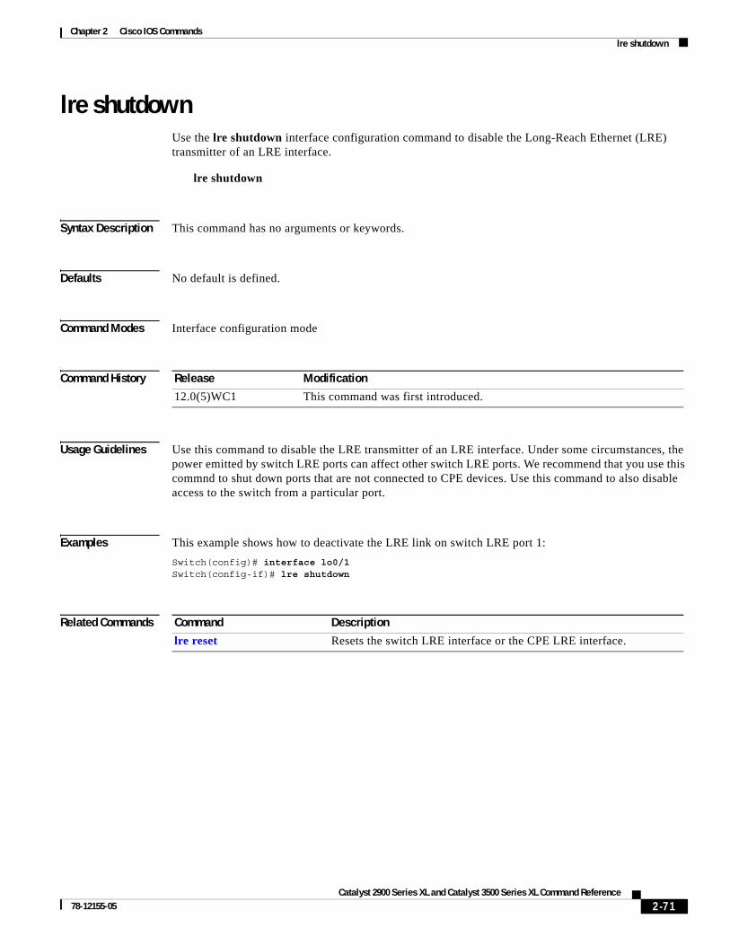
Chapter 2 Cisco IOS Commandslre shutdown
lre shutdownUse the lre shutdown interface configuration command to disable the Long-Reach Ethernet (LRE) transmitter of an LRE interface.
lre shutdown
Syntax Description This command has no arguments or keywords.
Defaults No default is defined.
Command Modes Interface configuration mode
Command History
Usage Guidelines Use this command to disable the LRE transmitter of an LRE interface. Under some circumstances, the power emitted by switch LRE ports can affect other switch LRE ports. We recommend that you use this commnd to shut down ports that are not connected to CPE devices. Use this command to also disable access to the switch from a particular port.
Examples This example shows how to deactivate the LRE link on switch LRE port 1:
Switch(config)# interface lo0/1Switch(config-if)# lre shutdown
Related Commands
Release Modification
12.0(5)WC1 This command was first introduced.
Command Description
lre reset Resets the switch LRE interface or the CPE LRE interface.
2-71Catalyst 2900 Series XL and Catalyst 3500 Series XL Command Reference
78-12155-05

Chapter 2 Cisco IOS Commandslre upgrade default family device-family binary
lre upgrade default family device-family binaryUse the lre upgrade default family global configuration command to define a map between a Long-Reach Ethernet (LRE) device type and an LRE binary.
lre upgrade default family device-family [model model [revision revision]]binary LRE binary
no lre upgrade default family device-family [model model [revision revision]] binary LRE binary
Syntax Description
Defaults No default is defined. The system selects the binary file.
Command Modes Global configuration mode
Command History
Usage Guidelines Use the lre upgrade default family device-family binary configuration command to override the default behavior for upgrading LRE firmware. This command is useful when you want to upgrade all CPE devices or local controllers of a given family to an LRE binary version.
Note The name of the LRE binary must by entered as it appears on Flash memory. Use show lre upgrade binaries to determine the flash file name of an LRE binary.
Examples This example shows how to configure all CISCO585-LRE CPE devices to upgrade and use LRE binary file CISCO-585-LRE_vdslsngl_51.00.00:
Switch(config)# lre upgrade default family CISCO585-LRE binary CISCO585-LRE_vdslsngl_51.00.00.bin
Switch(config)#
device-family Type of device that contains the chipset to be upgraded. Valid values are CISCO575-LRE, CISCO585-LRE, and CISCO2900-LRE.
model (Optional) Model number of the device family, for example, a model could be CISCO585-LRE.
revision (Optional) Revision of the target device.
LRE binary LRE binary file being applied.
Release Modification
12.1(11)YJ This command was first introduced.
2-72Catalyst 2900 Series XL and Catalyst 3500 Series XL Command Reference
78-12155-05

Chapter 2 Cisco IOS Commandslre upgrade default family device-family binary
Related Commands Command Description
controller LongReachEthernet
Entry for controller submode.
show lre upgrade binaries Displays the LRE binaries present on the system Flash memory.
show lre upgrade version Displays the version of binaries on local and remote ports in the switch.
upgrade binary Configures upgrades on either end of an LRE link.
upgrade preserve Prevents an upgrade of the local CPE controller and all remote CPE devices connected to it.
2-73Catalyst 2900 Series XL and Catalyst 3500 Series XL Command Reference
78-12155-05

Chapter 2 Cisco IOS Commandsmac-address-table aging-time
mac-address-table aging-timeUse the mac-address-table aging-time global configuration command to set the length of time that a dynamic entry remains in the MAC address table after the entry is used or updated. Use the no form of this command to use the default aging-time interval. The aging time applies to all VLANs.
mac-address-table aging-time age
no mac-address-table aging-time
Syntax Description
Defaults The default is 300 seconds.
Command Modes Global configuration
Command History
Usage Guidelines If hosts do not transmit continuously, increase the aging time to record the dynamic entries for a longer time. This can reduce the possibility of flooding when the hosts transmit again.
Examples This example shows how to set the aging time to 200 seconds:
Switch(config)# mac-address-table aging-time 200
You can verify the previous command by entering the show mac-address-table user EXEC command.
Related Commands
age Number from 10 to 1000000 (seconds).
Release Modification
11.2(8)SA This command was first introduced.
Command Description
clear mac-address-table Deletes entries from the MAC address table.
mac-address-table dynamic Adds dynamic addresses to the MAC address table.
mac-address-table secure Adds secure addresses to the MAC address table.
port block Blocks the flooding of unknown unicast or multicast packets to a port.
show cgmp Displays the state of the CGMP-learned multicast groups and routers.
show mac-address-table Displays the MAC address table.
2-74Catalyst 2900 Series XL and Catalyst 3500 Series XL Command Reference
78-12155-05

Chapter 2 Cisco IOS Commandsmac-address-table dynamic
mac-address-table dynamicUse the mac-address-table dynamic global configuration command to add dynamic addresses to the MAC address table. Dynamic addresses are automatically added to the address table and dropped from it when they are not in use. Use the no form of this command to remove dynamic entries from the MAC address table.
mac-address-table dynamic hw-addr interface [atm slot/port] [vlan vlan-id]
no mac-address-table dynamic hw-addr [vlan vlan-id]
Syntax Description
Command Modes Global configuration
Command History
Usage Guidelines If the variable vlan-id is omitted and the no form of the command is used, the MAC address is removed from all VLANs.
hw-addr MAC address added to or removed from the table.
interface Port to which packets destined for hw-addr are forwarded.
atm slot/port (Optional) Add dynamic addresses to ATM module in slot 1 or 2. The port is always 0 for an ATM interface.
vlan vlan-id (Optional) The interface and vlan parameters together specify a destination to which packets destined for hw-addr are forwarded.
The vlan keyword is optional if the port is a static-access or dynamic-access VLAN port. The VLAN assigned to the port is then assumed to be that of the port associated with the MAC address.
Note When this command is entered on a dynamic-access port, queries to the VLAN Membership Policy Server (VMPS) do not occur. The VMPS cannot verify that the address is allowed or determine to which VLAN the port should be assigned. Use this command only for testing purposes.
The vlan keyword is required for multi-VLAN and trunk ports. This keyword is required on trunk ports to specify to which VLAN the dynamic address is assigned.
The vlan-id is the ID of the VLAN to which packets destined for hw-addr are forwarded. Valid IDs are 1 to 1005; do not enter leading zeros.
Release Modification
11.2(8)SA This command was first introduced.
11.2(8)SA3 The vlan keyword was added.
11.2(8)SA5 The atm keyword was added.
2-75Catalyst 2900 Series XL and Catalyst 3500 Series XL Command Reference
78-12155-05

Chapter 2 Cisco IOS Commandsmac-address-table dynamic
Examples This example shows how to add a MAC address on port fa1/1 to VLAN 4:
Switch(config)# mac-address-table dynamic 00c0.00a0.03fa fa1/1 vlan 4
You can verify the previous command by entering the show mac-address-table user EXEC command.
Related Commands Command Description
clear mac-address-table Deletes entries from the MAC address table.
mac-address-table aging-time Specifies the length of time that a dynamic entry remains in the MAC address table after the entry is used or updated.
mac-address-table static Adds static addresses to the MAC address table.
show mac-address-table Displays the MAC address table.
2-76Catalyst 2900 Series XL and Catalyst 3500 Series XL Command Reference
78-12155-05
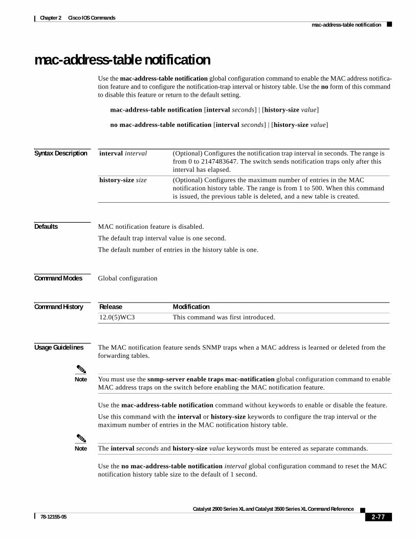
Chapter 2 Cisco IOS Commandsmac-address-table notification
mac-address-table notification Use the mac-address-table notification global configuration command to enable the MAC address notifica-tion feature and to configure the notification-trap interval or history table. Use the no form of this command to disable this feature or return to the default setting.
mac-address-table notification [interval seconds] | [history-size value]
no mac-address-table notification [interval seconds] | [history-size value]
Syntax Description
Defaults MAC notification feature is disabled.
The default trap interval value is one second.
The default number of entries in the history table is one.
Command Modes Global configuration
Command History
Usage Guidelines The MAC notification feature sends SNMP traps when a MAC address is learned or deleted from the forwarding tables.
Note You must use the snmp-server enable traps mac-notification global configuration command to enable MAC address traps on the switch before enabling the MAC notification feature.
Use the mac-address-table notification command without keywords to enable or disable the feature.
Use this command with the interval or history-size keywords to configure the trap interval or the maximum number of entries in the MAC notification history table.
Note The interval seconds and history-size value keywords must be entered as separate commands.
Use the no mac-address-table notification interval global configuration command to reset the MAC notification history table size to the default of 1 second.
interval interval (Optional) Configures the notification trap interval in seconds. The range is from 0 to 2147483647. The switch sends notification traps only after this interval has elapsed.
history-size size (Optional) Configures the maximum number of entries in the MAC notification history table. The range is from 1 to 500. When this command is issued, the previous table is deleted, and a new table is created.
Release Modification
12.0(5)WC3 This command was first introduced.
2-77Catalyst 2900 Series XL and Catalyst 3500 Series XL Command Reference
78-12155-05

Chapter 2 Cisco IOS Commandsmac-address-table notification
Use the no mac-address-table notification history-size global configuration command to reset the MAC notification history table size to the default of one.
Examples This example shows how to enable the MAC notification feature:
Switch(config)# mac-address-table notification
This example shows how to set the notification trap interval to 60 seconds:
Switch(config)# mac-address-table notification interval 60
This example shows how to set the number of entries in the history table to 32:
Switch(config)# mac-address-table notification history-size 32
You can verify this command by entering the show mac-address-table notification user EXEC command.
Related Commands snmp-server enable traps mac-notification Enables the MAC-notification traps on a port.
show mac-address-table notification Displays MAC-notification parameters.
2-78Catalyst 2900 Series XL and Catalyst 3500 Series XL Command Reference
78-12155-05

Chapter 2 Cisco IOS Commandsmac-address-table secure
mac-address-table secureUse the mac-address-table secure global configuration command to add secure addresses to the MAC address table. Use the no form of this command to remove secure entries from the MAC address table.
mac-address-table secure hw-addr interface [atm slot/port] [vlan vlan-id]
no mac-address-table secure hw-addr [vlan vlan-id]
Syntax Description
Command Modes Global configuration
Command History
Usage Guidelines Secure addresses can be assigned only to one port at a time. Therefore, if a secure address table entry for the specified MAC address and VLAN already exists on another port, it is removed from that port and assigned to the specified one.
Dynamic-access ports cannot be configured with secure addresses.
Examples This example shows how to add a secure MAC address to VLAN 6 of port fa1/1:
Switch(config)# mac-address-table secure 00c0.00a0.03fa fa1/1 vlan 6
This example shows how to add a secure MAC address to ATM port 2/1:
Switch(config)# mac-address-table secure 00c0.00a0.03fa atm 2/1
You can verify the previous command by entering the show mac-address-table user EXEC command.
hw-addr MAC address that is added to the table.
interface Port to which packets destined for hw-addr are forwarded.
atm slot/port (Optional) Add secure address to the Asynchronous Transfer Mode (ATM) module in slot 1 or 2. The port is always 0 for an ATM interface.
vlan vlan-id (Optional) The interface and vlan parameters together specify a destination to which packets destined for hw-addr are forwarded.
The vlan keyword is optional if the port is a static-access VLAN port. The VLAN assigned to the port is then assumed to be that of the port associated with the MAC address. This keyword is required for multi-VLAN and trunk ports.
The vlan-id is the ID of the VLAN to which secure entries are added. Valid IDs are 1 to 1005; do not enter leading zeros.
Release Modification
11.2(8)SA This command was first introduced.
11.2(8)SA3 The vlan keyword was added.
11.2(8)SA5 The atm keyword was added.
2-79Catalyst 2900 Series XL and Catalyst 3500 Series XL Command Reference
78-12155-05

Chapter 2 Cisco IOS Commandsmac-address-table secure
Related Commands Command Description
clear mac-address-table Deletes entries from the MAC address table.
mac-address-table aging-time Specifies the length of time that a dynamic entry remains in the MAC address table after the entry is used or updated.
mac-address-table dynamic Adds dynamic addresses to the MAC address table.
mac-address-table static Adds static addresses to the MAC address table.
show mac-address-table Displays the MAC address table.
2-80Catalyst 2900 Series XL and Catalyst 3500 Series XL Command Reference
78-12155-05

Chapter 2 Cisco IOS Commandsmac-address-table static
mac-address-table staticUse the mac-address-table static global configuration command to add static addresses to the MAC address table. Use the no form of this command to remove static entries from the MAC address table.
mac-address-table static hw-addr in-port out-port-list [atm slot/port] [vlan vlan-id]
no mac-address-table static hw-addr [in-port in-port] [out-port-list out-port-list] [vlan vlan-id]
Syntax Description
Command Modes Global configuration
Command History
hw-addr MAC address to add to the address table.
in-port Input port from which packets received with a destination address of hw-addr are forwarded to the list of ports in the out-port-list. The in-port must belong to the same VLAN as all the ports in the out-port-list.
out-port-list List of ports to which packets received on ports in in-port are forwarded. All ports in the list must belong to the same VLAN.
atm slot/port (Optional) Add static addresses to Asynchronous Transfer Mode (ATM) module in slot 1 or 2. The port is always 0 for an ATM interface.
vlan vlan-id (Optional) The interface and vlan parameters together specify a destination to which packets destined for the specified MAC address are forwarded.
The vlan keyword is optional if all the ports specified by in-port and out-port-list are static-access VLAN ports. The VLAN assigned to the ports is assumed. This keyword is required for multi-VLAN and trunk ports.
Dynamic-access ports cannot be included in static addresses as either the source (inport) or destination (outport).
The vlan keyword is required on trunk ports to specify to which VLAN the static address is assigned.
The vlan-id is the ID of the VLAN to which static address entries are forwarded. Valid IDs are 1 to 1005; do not enter leading zeros.
Release Modification
11.2(8)SA This command was first introduced.
11.2(8)SA3 The vlan keyword was added.
11.2(8)SA5 The atm keyword was added.
2-81Catalyst 2900 Series XL and Catalyst 3500 Series XL Command Reference
78-12155-05

Chapter 2 Cisco IOS Commandsmac-address-table static
Usage Guidelines When a packet is received on the input port, it is forwarded to the VLAN of each port that you specify for the out-port-list. Different input ports can have different output-port lists for each static address. Adding a static address already defined as one modifies the port map (vlan and out-port-list) for the input port specified.
If the variable vlan-id is omitted and the no form of the command is used, the MAC address is removed from all VLANs.
Traffic from a static address is only accepted from a port defined in the in-port variable.
Dynamic-access ports cannot be configured as the source or destination port in a static address entry.
Examples This example shows how to add a static address with port 1 as an input port and ports 2 and 8 of VLAN 4 as output ports:
Switch(config)# mac-address-table static c2f3.220a.12f4 fa0/1 fa0/2 fa0/8 vlan 4
You can verify the previous command by entering the show mac-address-table user EXEC command.
Related Commands Command Description
clear mac-address-table Deletes entries from the MAC address table.
mac-address-table aging-time Specifies the length of time that a dynamic entry remains in the MAC address table after the entry is used or updated.
mac-address-table dynamic Adds dynamic addresses to the MAC address table.
mac-address-table secure Adds secure addresses to the MAC address table.
show mac-address-table Displays the MAC address table.
2-82Catalyst 2900 Series XL and Catalyst 3500 Series XL Command Reference
78-12155-05

Chapter 2 Cisco IOS Commandsmanagement
managementUse the management interface configuration command to shut down the current management VLAN interface and to enable the new management VLAN interface. The management VLAN is the VLAN used for managing a cluster of switches. To use this VLAN for switch management, apply this VLAN to a switched virtual interface or to the management interface. The default management VLAN is VLAN 1; however, it can be changed to a new management interface on a different VLAN with valid IDs from 1 to 1001.
This command also copies the current management VLAN IP information to the new management VLAN interface if no new IP address or network mask is provided. It also copies the cluster standby group configuration to the new management VLAN.
management
Syntax Description This command has no arguments or keywords.
Defaults No default is defined.
Command Modes Interface configuration
Command History
Usage Guidelines No default management or no management command exists to return the management VLAN to its default state.
The management command is not written to the configuration file, and it is not displayed in the output of the show running-config privileged EXEC command.
Before entering the management command, make sure that these conditions exist:
• You must be able to move your network management station to a switch port assigned to the same VLAN as the new management VLAN. (Depending on your network topology, you might not need to move your network management station: for example, you have ISL routing configured on a router between two VLANs.)
• Connectivity through the network must exist from the network management station to all switches involved in the management VLAN change.
• The switch must already have a port assigned to the same VLAN as the management VLAN.
Use the management command to change the management VLAN on a single switch. Use the global cluster management-vlan n configuration command on the command switch to change the management VLAN on the entire cluster.
Release Modification
12.0(5)XP This command was first introduced.
2-83Catalyst 2900 Series XL and Catalyst 3500 Series XL Command Reference
78-12155-05

Chapter 2 Cisco IOS Commandsmanagement
Examples This example shows how to shut down the current management VLAN interface and start VLAN 2 as the management VLAN:
Switch# configure terminalSwitch(config)# interface vlan 2Switch(config-subif)# ip address 172.20.128.176 255.255.255.0Switch(config-subif)# managementSwitch(config-subif)# exitSwitch(config)#
This example shows how to copy the IP address and network mask from the current management VLAN to VLAN 2 and make VLAN 2 the management VLAN:
Switch# configure terminalSwitch(config)# interface vlan 2Switch(config-subif)# managementSwitch(config-subif)# exitSwitch(config)#
You can verify the previous command by entering the show interface vlan number user EXEC command.
Related Commands Command Description
cluster management-vlan Changes the management VLAN for the entire cluster.
interface vlan Configures an interface type, creates a switch virtual interface to be used as the management VLAN interface, and enters interface configuration mode.
show interface vlan number Displays the administrative and operational status of a switching (nonrouting) port.
2-84Catalyst 2900 Series XL and Catalyst 3500 Series XL Command Reference
78-12155-05

Chapter 2 Cisco IOS Commandsmargin
marginUse the margin interface configuration command to specify the margin value used to determine link quality during Long-Reach Ethernet (LRE) rate selection. Use the no form of this command to restore the default value.
margin {downstream value | upstream value}
no margin {downstream value | upstream value}
Syntax Description
Defaults The default is 0 dB.
Command Modes Interface configuration mode
Command History
Usage Guidelines When rate selection is running, the signal-to-noise ratio (SNR) shows the link quality. The switch does not provide any internal mechanism to assure link quality. There can be different requirements for link quality, depending on the required bit-error rate and the noise level of the environment. A noisier environment would require a higher SNR to be able to provide a stable link. A lower bit-error rate would require a higher SNR. Typically a 6-dB margin provides an error rate of 10-21 bits.
In order to provide link stability, you should add a margin to the required SNR. You can configure your margins to an amount that is appropriate for the noise level of your environment. Increasing the margin requirement can cause the system to choose a lower profile, which would in turn translate to a lower rate but with a longer reach.
The switch does not guarantee any margins after a link is activated. Margins are only guaranteed when the link is established. When a link is activated, if the SNR requirements do not match the configured margin level, the link is not established.
Downstream means the remote end of the link and upstream the local end. The link has to satisfy both the local and remote margin requirements. If either one is not met, the link is advertised as down. This command has no significance if rate selection is not running on this interface.
Note Setting a margin requirement might cause the system to choose another profile, which might translate to a lower rate but a longer reach.
For a full discussion of link stability and margins, refer to the Catalyst 2900 Series XL and Catalyst 3500 Series XL Software Configuration Guide.
downstream value The value at the remote end of the link. Valid entries are from 0 to 10 dB.
upstream value The value at the local end of the link. Valid entries are from 0 to 10 dB.
Release Modification
12.0(5)WC6 This command was first introduced.
2-85Catalyst 2900 Series XL and Catalyst 3500 Series XL Command Reference
78-12155-05

Chapter 2 Cisco IOS Commandsmargin
Examples This example shows how to specify a margin of 2 dB for both upstream and downstream. If the SNR is 2 dB above the theoretical minimum for the chosen profile when the link is established, the link is classified as down, and the next profile in the sequence is attempted.
Switch(config-if)# margin upstream 2 downstream 2Switch(config-if)#
This example shows show to specify a margin of 1 dB for downstream:
Switch(config-if)# margin downstream 1Switch(config-if)#
Related Commands Command Description
lre rate selection sequence Assigns a rate selection sequence for the entire switch.
rate selection Enables rate selection on a specific port.
rate selection sequence Assigns a rate selection sequence for a specific port.
2-86Catalyst 2900 Series XL and Catalyst 3500 Series XL Command Reference
78-12155-05

Chapter 2 Cisco IOS Commandsmvr (global configuration)
mvr (global configuration)Use the mvr global configuration command without keywords to enable the multicast VLAN registration (MVR) feature on the switch. Use the no form of this command to disable MVR and its options.
Use the command with keywords to set the maximum time to wait for a query reply before removing a port from group membership and to specify the MVR multicast VLAN. Use the no form of the commands to return the switch to the default settings.
mvr [group ip-address [count] [querytime value] [vlan vlan-id] ]
no mvr [group ip-address [count] [querytime value] [vlan vlan-id] ]
Syntax Description
Defaults MVR is disabled.
The switch hardware determines the maximum number of MVR entries.
No IP multicast addresses are configured on the switch.
The default count is 1.
The default query response time is 0.5 second.
The default multicast VLAN is VLAN 1.
Command Modes Global configuration
Command History
group ip-address Statically configure an MVR group IP multicast address on the switch.
Use the no form of this command to remove a statically configured IP multicast address or contiguous addresses or, when no IP address is entered, to remove all statically configured MVR IP multicast addresses.
querytime value (Optional) Set the maximum time to wait for IGMP report memberships on a receiver port. This time only applies to receiver-port leave processing. When an IGMP query is sent from a receiver port, the switch waits for the default or configured MVR querytime for an IGMP group membership report before removing the port from multicast group membership.
The value is the response time in units of tenths of a second. The default is 0.5 second.
Use the no form of the command to return to the default setting.
vlan vlan-id Specify the VLAN on which MVR multicast data is expected to be received. This is also the VLAN to which all the source ports belong.
Release Modification
12.0(5)XW This command was first introduced.
2-87Catalyst 2900 Series XL and Catalyst 3500 Series XL Command Reference
78-12155-05

Chapter 2 Cisco IOS Commandsmvr (global configuration)
Usage Guidelines The switch hardware determines the maximum number of MVR entries.
Use the mvr group command to statically set all the IP multicast addresses that will take part in MVR. Any multicast data sent to a configured multicast address is sent to all the source ports on the switch and to all receiver ports that have registered to receive data on that IP multicast address.
Note The mvr group command prevents adding IP multicast addresses that cause address aliasing. Each IP multicast address translates to a multicast 48-bit MAC address. If the IP address being configured translates (aliases) to the same 48-bit MAC address as a previously configured IP multicast address, the command fails.
The mvr querytime parameter applies only to receiver ports. You should configure the query time before enabling MVR and configuring the static multicast groups. You can change the query time after MVR is enabled, but you receive a warning message:
Warning: Changing MVR query response time while MVR is running.
Set the MVR multicast VLAN before the multicast addresses are configured. If it is necessary to change the multicast VLAN, disable MVR, change the VLAN number, and then reenable MVR. Previously configured groups are restored.
Examples This example shows how to enable MVR:
Switch(config)# mvr
This example shows how to disable MVR:
Switch(config)# no mvr
Use the show mvr privileged EXEC command to display the setting for maximum multicast groups.
This example shows how to configure 228.1.23.4 as an IP multicast address:
Switch(config)# mvr group 228.1.23.4
This command fails because of address aliasing:
Switch(config)# mvr group 230.1.23.4
Cannot add this IP address - aliases with previously configured IP address 228.1.23.4.
This example shows how to configure ten contiguous IP multicast groups with multicast addresses from 228.1.23.1 to 228.1.23.10:
Switch(config)# mvr group 228.1.23.1 10
This example shows how to delete the previously configured ten IP multicast addresses:
Switch(config)# no mvr group 228.1.23.1 10
This example shows how to delete all previously configured IP multicast addresses:
Switch(config)# no mvr group
Use the command show mvr members to display the IP multicast group addresses configured on the switch.
This example shows how to set the maximum query response time as 1 second (10 tenths):
Switch(config)# mvr querytime 10
2-88Catalyst 2900 Series XL and Catalyst 3500 Series XL Command Reference
78-12155-05

Chapter 2 Cisco IOS Commandsmvr (global configuration)
This example shows how to return the maximum query response time to the default setting of 0.5 second:
Switch(config)# no mvr querytime
This example shows how to set VLAN 2 as the multicast VLAN:
Switch(config)# mvr vlan 2
You can verify your settings by entering the show mvr privileged EXEC command.
Related Commands Command Description
mvr (interface configuration) Configures MVR source or receiver ports.
show mvr Displays MVR global parameters or port parameters.
show mvr members Displays all receiver ports that are members of an MVR multicast group.
show mvr interface Displays the configured MVR interfaces.
2-89Catalyst 2900 Series XL and Catalyst 3500 Series XL Command Reference
78-12155-05

Chapter 2 Cisco IOS Commandsmvr (interface configuration)
mvr (interface configuration)Use the mvr interface configuration command to configure a port as a multicast VLAN registration (MVR) receiver or source port and set the Immediate Leave feature.
Use the no form of the commands to return the port to the default settings.
mvr {type {source | receiver} | immediate}
no mvr {type {source | receiver} | immediate}
Syntax Description
Defaults A port is configured as neither receiver nor source.
The Immediate Leave feature is disabled on all ports.
No receiver port is a member of any configured multicast group.
Command Modes Interface configuration
Command History
Usage Guidelines Configure a port as a source port if that port should be able to both send and receive multicast data bound for the configured multicast groups. Multicast data is received on all ports configured as source ports.
Configure a port as a receiver port if that port should only be able to receive multicast data and should not be able to send multicast data to the configured multicast groups. None of the receiver ports receives multicast data unless it sends an Internet Group Management Protocol (IGMP) group join message for a multicast group.
Note For the Catalyst 2900 XL and Catalyst 3500 XL switches, all receiver ports must belong to the same VLAN and must not be trunk ports.
type value (Optional) Configure the port as an MVR receiver port or source port.
The default port type is neither an MVR source nor receiver port. The no mvr type command resets the port to the default.
source Configure the port as an uplink port that can send and receive multicast data for the configured multicast groups. All source ports on a switch belong to a single multicast VLAN.
receiver Configure the port as a subscriber port that can only receive multicast data. Receiver ports cannot belong to the multicast VLAN.
immediate Enable the Immediate Leave feature of MVR on a port. Use the no form of this command to disable the feature.
Release Modification
12.0(5)XW This command was first introduced.
2-90Catalyst 2900 Series XL and Catalyst 3500 Series XL Command Reference
78-12155-05

Chapter 2 Cisco IOS Commandsmvr (interface configuration)
A port that is not taking part in MVR should not be configured as an MVR receiver port or source port. This port is a normal switch port and is able to send and receive multicast data with normal switch behavior.
The Immediate Leave feature applies only to receiver ports. When the Immediate Leave feature is enabled, a receiver port leaves a multicast group more quickly. When the switch receives an IGMP leave message from a group on a receiver port, it sends out an IGMP query on that port and waits for IGMP group membership reports. If no reports are received in a configured time period, the receiver port is removed from multicast group membership. With Immediate Leave, an IGMP query is not sent from the receiver port on which the IGMP leave was received. As soon as the leave message is received, the receiver port is removed from multicast group membership, thus speeding up leave latency.
Enable the Immediate Leave feature only on receiver ports to which a single receiver device is connected.
All receiver ports must be on the same VLAN and cannot be trunk ports. A receiver configured as a static member of a multicast group remains a member until statically removed from membership.
MVR does not support IGMP dynamic joins. You must configure static multicast addresses for receiver ports.
The receiver VLAN is the VLAN to which the first configured receiver port belongs. If the first receiver port is a dynamic port with an unassigned VLAN, it becomes an inactive receiver port and does not take part in MVR until it is assigned to the receiver VLAN. The receiver VLAN is reset whenever there are no remaining receiver ports on the switch (active or inactive), which means that the receiver VLAN might change every time the first receiver port is configured.
Examples This example shows how to configure port 0/1 as an MVR receiver port:
Switch(config)# interface FastEthernet 0/1Switch(config-if)# mvr type receiver
This example shows how to configure port 0/3 as an MVR source port:
Switch(config)# interface FastEthernet 0/3Switch(config-if)# mvr type source
This example shows how to remove port 0/1 from taking part in MVR:
Switch(config)# interface FastEthernet 0/1Switch(config-if))# no mvr
This example shows how to display configured receiver ports and source ports.:
Switch# show mvr interface
MVR PORTSPort: Fa0/1 Type: RECEIVER Status: ACTIVEPort: Fa0/2 Type: RECEIVER Status: ACTIVEPort: Fa0/3 Type: SOURCE Status: ACTIVE
This example shows how to enable Immediate Leave on Fast Ethernet port 0/1:
Switch(config)# interface FastEthernet 0/1Switch(config-if)# mvr immediate
This example shows how to disable Immediate Leave on port 0/1:
Switch(config)# interface FastEthernet 0/1Switch(config-if)# no mvr immediate
2-91Catalyst 2900 Series XL and Catalyst 3500 Series XL Command Reference
78-12155-05

Chapter 2 Cisco IOS Commandsmvr (interface configuration)
To display whether or not Immediate Leave is enabled on an interface, use the command show mvr for the interface as in this example:
Switch# show mvr interface fastethernet 0/1Interface: Fa0/1 Immediate Leave: FALSE
Use the show mvr members privileged EXEC command to display the multicast group address, the VLAN, and the receiver port.
Related Commands Command Description
mvr (global configuration) Enables multicast VLAN registration on the switch.
show mvr Displays MVR global parameters or port parameters.
show mvr members Displays all receiver ports that are members of an MVR multicast group.
show mvr interface Displays the configured MVR ports.
2-92Catalyst 2900 Series XL and Catalyst 3500 Series XL Command Reference
78-12155-05

Chapter 2 Cisco IOS Commandsntp broadcast client
ntp broadcast clientUse the ntp broadcast client interface configuration command to allow the system to receive Network Time Protocol (NTP) broadcast packets on an interface. Use the no form of the command to disable this capability.
ntp broadcast client
no ntp broadcast client
Syntax Description This command has no arguments or keywords.
Defaults Broadcast client mode is disabled.
Command Modes Interface configuration
Command History
Usage Guidelines Use this command to allow the system to listen to broadcast packets on an interface-by-interface basis. Enter this command on the management VLAN interface. By default, the management VLAN is VLAN 1, but you can configure a different VLAN as the management VLAN.
Examples This example shows how to synchronize the router to NTP packets that are broadcast on interface VLAN1:
Switch(config-if)# interface vlan1Switch(config-if)# ntp broadcast client
You can verify the previous commands by entering the show running-config privileged EXEC command.
Related Commands
Release Modification
11.2(8)SA6 This command was first introduced.
Command Description
show running-config Displays the running configuration on the switch.
2-93Catalyst 2900 Series XL and Catalyst 3500 Series XL Command Reference
78-12155-05

Chapter 2 Cisco IOS Commandsntp broadcast destination
ntp broadcast destinationUse the ntp broadcast destination interface configuration command to configure a Network Time Protocol (NTP) server or peer to restrict the broadcast of NTP frames to the IP address of a designated client or a peer. Use the no form of the command to return the setting to its default.
ntp broadcast destination IP-address
no ntp broadcast destination
Syntax Description
Defaults No IP address or host name is assigned.
Command Modes Interface configuration
Command History
Usage Guidelines Enter this command on the management VLAN interface. By default, the management VLAN is VLAN 1, but you can configure a different VLAN as the management VLAN.
Examples This example shows how to restrict the broadcast of NTP frames to a specific IP address:
Switch(config-if)# interface vlan1Switch(config-if)# ntp broadcast destination 172.20.128.176
Related Commands
IP-address IP address or host name of a designated client or a peer.
Release Modification
11.2(8)SA6 This command was first introduced.
Command Description
ntp broadcast client Allows the system to receive NTP broadcast packets on an interface.
2-94Catalyst 2900 Series XL and Catalyst 3500 Series XL Command Reference
78-12155-05

Chapter 2 Cisco IOS Commandsntp broadcast key
ntp broadcast keyUse the ntp broadcast key interface configuration command to configure a Network Time Protocol (NTP) server or peer to broadcast NTP frames with the authentication key that is embedded in the NTP packet. Use the no form of the command to return the setting to its default.
ntp broadcast key number
no ntp broadcast key
Syntax Description
Defaults No NTP broadcast key is defined.
Command Modes Interface configuration
Command History
Usage Guidelines Enter this command on the management VLAN interface. By default, the management VLAN is VLAN 1, but you can configure a different VLAN as the management VLAN.
Examples This example shows how to assign an authentication key to outgoing NTP frames:
Switch(config)# interface vlan1Switch(config-if)# ntp broadcast key 1
Related Commands
number The NTP authentication key that is embedded in the NTP packet. The range is from 0 to 4294967295.
Release Modification
11.2(8)SA6 This command was first introduced.
Command Description
ntp broadcast client Allows the system to receive NTP broadcast packets on an interface.
2-95Catalyst 2900 Series XL and Catalyst 3500 Series XL Command Reference
78-12155-05

Chapter 2 Cisco IOS Commandsntp broadcast version
ntp broadcast versionUse the ntp broadcast interface configuration command to specify that a specific interface should send Network Time Protocol (NTP) broadcast packets. Use the no form of the command to disable this capability.
ntp broadcast version number
no ntp broadcast
Syntax Description
Defaults Version 3 is the default.
Command Modes Interface configuration
Command History
Usage Guidelines Cisco IOS uses NTP version 3 by default. If the network (NTP server) is using NTP version 2, and synchronization does not occur, use NTP version 2.
Enter this command on the management VLAN interface. By default, the management VLAN is VLAN 1, but you can configure a different VLAN as the management VLAN.
Examples This example shows how to configure interface VLAN 1 to send NTP version 2 packets:
Switch(config-if)# interface vlan1Switch(config-if)# ntp broadcast version 2
You can verify the previous commands by entering the show running-config privileged EXEC command.
Related Commands
number The range is 1 to 3.
Release Modification
11.2(8)SA6 This command was first introduced.
Command Description
ntp broadcast client Allows the system to receive NTP broadcast packets on an interface.
show running-config Displays the running configuration on the switch.
2-96Catalyst 2900 Series XL and Catalyst 3500 Series XL Command Reference
78-12155-05

Chapter 2 Cisco IOS Commandsntp max-associations
ntp max-associationsUse the ntp max-associations global configuration command to set the maximum number of Network Time Protocol (NTP) associations that are allowed on a server. Use the no form of this command to disable this feature.
ntp max-associations [number]
no ntp max-associations
Syntax Description
Defaults The number of NTP associations is 100.
Command Modes Global configuration
Command History
Usage Guidelines This command can control the number of peers that can use the switch to synchronize to it through NTP.
After you enable a switch as an NTP server, use this command to set the maximum number of associations that are allowed on a server.
Examples This example shows how to set the maximum number of NTP associations to 44:
Switch(config)# ntp max-associations 44
You can verify the previous command by entering the show running-config privileged EXEC command.
Related Commands
number (Optional) Specify the number of NTP associations. The range is from 0 to 4294967295.
Release Modification
11.2(8)SA6 This command was first introduced.
Command Description
show running-config Displays the running configuration on the switch.
2-97Catalyst 2900 Series XL and Catalyst 3500 Series XL Command Reference
78-12155-05

Chapter 2 Cisco IOS Commandsntp source
ntp sourceUse the ntp source global configuration command to use a particular source address in Network Time Protocol (NTP) packets. Use the no form of this command to remove the specified source address.
ntp source interface
no ntp source
Syntax Description
Defaults No source address is defined.
Command Modes Global configuration
Command History
Usage Guidelines Use this command when you want to use a particular source IP address for all NTP packets. The address is taken from the specified interface. This command is useful if the address on an interface cannot be used as the destination for reply packets. If the source keyword is present on an ntp server or ntp peer command, that value overrides the global value.
Examples This example shows how to configure the switch to use the IP address of VLAN1 as the source address of all outgoing NTP packets:
Switch(config)# ntp source vlan1
You can verify the previous command by entering the show running-config privileged EXEC command.
Related Commands
interface Any valid system interface name.
Release Modification
11.2(8)SA6 This command was first introduced.
Command Description
ntp source Allows the switch system clock to be synchronized by a time server.
show running-config Displays the running configuration on the switch.
2-98Catalyst 2900 Series XL and Catalyst 3500 Series XL Command Reference
78-12155-05

Chapter 2 Cisco IOS Commandsport block
port blockUse the port block interface configuration command to block the flooding of unknown unicast or multicast packets to a port. Use the no form of this command to resume normal forwarding.
port block {unicast | multicast}
no port block {unicast | multicast}
Syntax Description
Defaults Flood unknown unicast and multicast packets to all ports.
Command Modes Interface configuration
Command History
Usage Guidelines The port block command cannot be entered for a network port.
If a trunk port is not a network port, the unicast keyword applies. The multicast keyword is supported on trunk ports. Both port block features affect all the VLANs associated with the trunk port.
Examples This example shows how to block the forwarding of multicast and unicast packets to a port:
Switch(config-if)# port block unicastSwitch(config-if)# port block multicast
You can verify the previous commands by entering the show port block user EXEC command.
Related Commands
unicast Packets with unknown unicast addresses are not forwarded to this port.
multicast Packets with unknown multicast addresses are not forwarded to this port.
Release Modification
11.2(8)SA This command was first introduced.
Command Description
show port block Displays the blocking of unicast or multicast flooding to a port.
2-99Catalyst 2900 Series XL and Catalyst 3500 Series XL Command Reference
78-12155-05

Chapter 2 Cisco IOS Commandsport group
port groupUse the port group interface configuration command to assign a port to a Fast EtherChannel or Gigabit EtherChannel port group. Up to 12 port groups can be created on a switch. Any number of ports can belong to a destination-based port group. Up to eight ports can belong to a source-based port group. Use the no form of this command to remove a port from a port group.
port group group-number [distribution {source | destination}]
no port group
Syntax Description
Defaults Port does not belong to a port group.
The default forwarding method is source.
Command Modes Interface configuration
Command History
Usage Guidelines An Asynchronous Transfer Mode (ATM) port is the only port that cannot belong to a port group. For all other ports, these restrictions apply:
• Do not group Fast Ethernet and Gigabit ports together.
• No port group member can be configured for Switched Port Analyzer (SPAN) port monitoring.
• No port group member can be enabled for port security.
• You can create up to 12 port groups. You can have source-based port groups and destination-based source groups. A source-based port group can have up to eight ports in its group. A destination-based port group can contain an unlimited number of ports in its group. You cannot mix source-based and destination-based ports in the same group. You can independently configure port groups that link switches, but you must consistently configure both ends of a port group.
group-number Port group number to which the port belongs. The range is from 1 to 12.
distribution {source | destination} (Optional) Forwarding method for the port group.
• source—Set the port to forward traffic to a port group based on the packet source address. This is the default forwarding method.
• destination—Set the port to forward traffic to a port group based on the packet destination address.
Release Modification
11.2(8)SA3 This command was first introduced.
2-100Catalyst 2900 Series XL and Catalyst 3500 Series XL Command Reference
78-12155-05
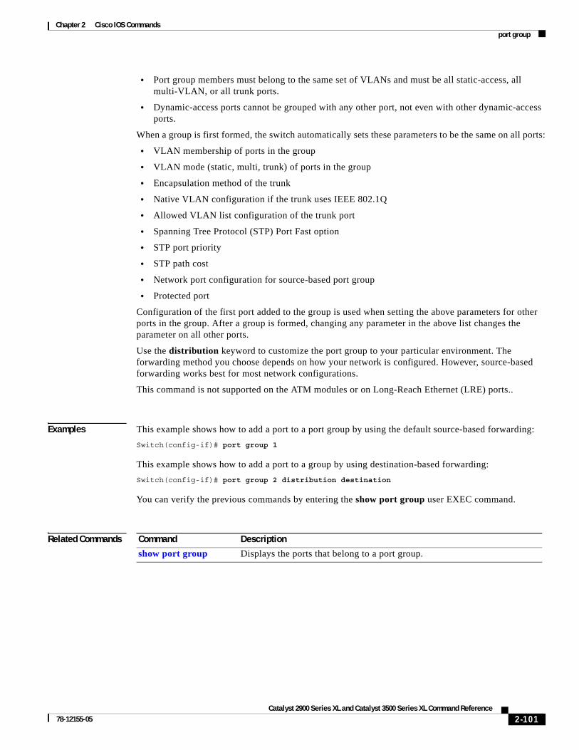
Chapter 2 Cisco IOS Commandsport group
• Port group members must belong to the same set of VLANs and must be all static-access, all multi-VLAN, or all trunk ports.
• Dynamic-access ports cannot be grouped with any other port, not even with other dynamic-access ports.
When a group is first formed, the switch automatically sets these parameters to be the same on all ports:
• VLAN membership of ports in the group
• VLAN mode (static, multi, trunk) of ports in the group
• Encapsulation method of the trunk
• Native VLAN configuration if the trunk uses IEEE 802.1Q
• Allowed VLAN list configuration of the trunk port
• Spanning Tree Protocol (STP) Port Fast option
• STP port priority
• STP path cost
• Network port configuration for source-based port group
• Protected port
Configuration of the first port added to the group is used when setting the above parameters for other ports in the group. After a group is formed, changing any parameter in the above list changes the parameter on all other ports.
Use the distribution keyword to customize the port group to your particular environment. The forwarding method you choose depends on how your network is configured. However, source-based forwarding works best for most network configurations.
This command is not supported on the ATM modules or on Long-Reach Ethernet (LRE) ports..
Examples This example shows how to add a port to a port group by using the default source-based forwarding:
Switch(config-if)# port group 1
This example shows how to add a port to a group by using destination-based forwarding:
Switch(config-if)# port group 2 distribution destination
You can verify the previous commands by entering the show port group user EXEC command.
Related Commands Command Description
show port group Displays the ports that belong to a port group.
2-101Catalyst 2900 Series XL and Catalyst 3500 Series XL Command Reference
78-12155-05

Chapter 2 Cisco IOS Commandsport monitor
port monitorUse the port monitor interface configuration command to enable Switch Port Analyzer (SPAN) port monitoring on a port. Use the no form of this command to return the port to its default value.
port monitor [interface | vlan vlan-id]
no port monitor [interface | vlan vlan-id]
Syntax Description
Defaults Port does not monitor any other ports.
Command Modes Interface configuration
Command History
Usage Guidelines Enabling port monitoring without specifying a port causes all other ports in the same VLAN to be monitored.
Entering the port monitor vlan 1 command causes monitoring of all traffic to and from the IP address configured on VLAN 1.
Asynchronous Transfer Mode (ATM) ports are the only ports that cannot be monitor ports. However, you can monitor ATM ports. These restrictions apply for ports that have port-monitoring capability:
• A monitor port cannot be in a Fast EtherChannel or Gigabit EtherChannel port group.
• A monitor port cannot be enabled for port security.
• A monitor port cannot be a multi-VLAN port.
• A monitor port must be a member of the same VLAN as the port monitored. VLAN membership changes are not allowed on monitor ports and ports being monitored.
• A monitor port cannot be a dynamic-access port or a trunk port. However, a static-access port can monitor a VLAN on a trunk, a multi-VLAN port, or a dynamic-access port. The VLAN monitored is the one associated with the static-access port.
• Port monitoring does not work if both the monitor and monitored ports are protected ports.
interface (Optional) Module type, slot, and port number for the SPAN to be enabled. The interface specified is the port to be monitored.
vlan vlan-id (Optional) ID of the VLAN to be monitored.
Note VLAN 1 is the only valid option.
Release Modification
11.2(8)SA This command was first introduced.
11.2(8)SA3 The vlan keyword was added.
2-102Catalyst 2900 Series XL and Catalyst 3500 Series XL Command Reference
78-12155-05

Chapter 2 Cisco IOS Commandsport monitor
Examples This example shows how to enable port monitoring on port fa0/2:
Switch(config-if)# port monitor fa0/2
You can verify the previous command by entering the show port monitor user EXEC command.
Related Commands Command Description
show port monitor Displays the ports for which SPAN port monitoring is enabled.
2-103Catalyst 2900 Series XL and Catalyst 3500 Series XL Command Reference
78-12155-05

Chapter 2 Cisco IOS Commandsport network
port networkUse the port network interface configuration command to define a port as the switch network port. All traffic with unknown unicast addresses is forwarded to the network port on the same VLAN. Use the no form of this command to return the port to the default value.
port network
no port network
Syntax Description This command has no arguments or keywords.
Defaults No network port is defined.
Command Modes Interface configuration
Command History
Usage Guidelines These restrictions apply to network ports:
• A network port can be a static-access port, a multi-VLAN port, a port group, or a trunk port. Both the multi-VLAN port and the trunk port become the network port for all the VLANs associated with that port.
• A network port cannot be an Asynchronous Transfer Mode (ATM), a secure, a monitor, a protected, or a dynamic-access port. You can assign a dynamic-access port to a VLAN in which another port is the network port.
• Each VLAN can have one network port.
• A network port cannot be in a destination-based port group.
• A network port cannot be on an ATM module.
• A network port cannot be a protected port.
Examples This example shows how to set a port as a network port:
Switch(config-if)# port network
You can verify the previous command by entering the show port network privileged EXEC command.
Related Commands
Release Modification
11.2(8)SA4 This command was first introduced.
Command Description
show port network Displays the network port defined for the switch or VLAN.
2-104Catalyst 2900 Series XL and Catalyst 3500 Series XL Command Reference
78-12155-05

Chapter 2 Cisco IOS Commandsport protected
port protectedUse the port protected interface configuration command to isolate unicast, multicast, and broadcast traffic at Layer 2 from other protected ports on the same switch. Use the no form of the command to disable the protected port.
port protected
no port protected
Syntax Description This command has no keywords or arguments.
Defaults No protected port is defined.
A protected port does not forward any unicast, multicast, or broadcast traffic to any other protected port.
A protected port continues to forward and receive unicast, multicast, and broadcast traffic to and from unprotected ports.
Command Modes Interface configuration
Command History
Usage Guidelines The port protection feature is local to the switch; communication between protected ports on the same switch is possible only through a Layer 3 device. To prevent communication between protected ports on different switches, you must configure the protected ports for unique VLANs on each switch and configure a trunk link between the switches.
A protected port cannot be a network port.
Port monitoring does not work if both the monitor and monitored ports are protected ports.
A protected port is different from a secure port.
Examples This example shows how to enable a protected port on interface fa0/3:
Switch(config)# interface fa0/3Switch(config-if)# port protected
You can verify the previous command by entering the show port protected user EXEC command.
Related Commands
Release Modification
12.0(5)XU This command was first introduced.
Command Description
show port protected Displays the ports that are in port-protected mode.
2-105Catalyst 2900 Series XL and Catalyst 3500 Series XL Command Reference
78-12155-05

Chapter 2 Cisco IOS Commandsport security
port securityUse the port security interface configuration command to enable port security on a port, to set the aging time for dynamic and static secure address entries, and to restrict the use of the port to a user-defined group of stations. Use the no form of this command to return the port to its default value.
port security [action {shutdown | trap} | aging | max-mac-count addresses]
no port security
Syntax Description
Defaults Port security is disabled.
When enabled, the default action is to generate an SNMP trap.
The port security aging feature is disabled. The default time is 0.
Command Modes Interface configuration
Command History
Usage Guidelines To enable aging for all dynamic and static secure addresses on a particular port, set the aging time to a value other than 0 for that port.
If you specify trap, use the snmp-server host global configuration command to configure the SNMP trap host to receive traps.
These restrictions apply to secure ports:
• A secure port cannot belong to a Fast EtherChannel or Gigabit EtherChannel port group.
• A secure port cannot have Switched Port Analyzer (SPAN) port monitoring enabled on it.
• A secure port cannot be a multi-VLAN port.
• A secure port cannot be a network port.
action {shutdown | trap} (Optional) Action to take when an address violation occurs on this port.
• shutdown—Disable the port when a security violation occurs.
• trap—Generate a Simple Network Management Protocol (SNMP) trap when a security violation occurs.
aging {time time} (Optional) Enable port security aging for this port and set the aging time. The range is 0 to 1440 minutes. If aging time is 0, aging is disabled for the port.
max-mac-count addresses (Optional) The maximum number of secure addresses that this port can support. The range is from 1 to 132.
Release Modification
11.2(8)SA This command was first introduced.
2-106Catalyst 2900 Series XL and Catalyst 3500 Series XL Command Reference
78-12155-05

Chapter 2 Cisco IOS Commandsport security
• A secure port cannot be an Asynchronous Transfer Mode (ATM) port.
• A secure port cannot be a dynamic-access port or a trunk port.
Examples This example shows how to enable port security and what action the port takes in case of an address violation (shutdown).
Switch(config-if)# port security action shutdown
This example shows how to set the port security aging time to 2 hours on port 1.
Switch(config)# interface fa0/1Switch(config-if)# port security aging time 120
This example shows how to set the maximum number of addresses that the port can learn to 8.
Switch(config-if)# port security max-mac-count 8
You can verify the previous commands by entering the show port security privileged EXEC command.
Related Commands Command Description
show port security Displays the port security settings defined for the port.
2-107Catalyst 2900 Series XL and Catalyst 3500 Series XL Command Reference
78-12155-05

Chapter 2 Cisco IOS Commandsport storm-control
port storm-controlUse the port storm-control interface configuration command to enable broadcast, multicast, or unicast storm control on a port. Use the no form of this command to disable storm control or one of the storm-control parameters on the port.
port storm-control {broadcast | multicast | unicast} {{action {filter | shutdown} | threshold {rising rising-number falling falling-number} | trap}}
no port storm-control {broadcast | multicast | unicast}
Syntax Description
Defaults Broadcast, multicast, and unicast storm control are disabled.
The rising thresholds are 500 broadcast packets per second, 2500 multicast packets per second, and 5000 unicast packets per second.
The falling thresholds are 250 broadcast packets per second, 1200 multicast packets per second, and 2500 unicast packets per second.
Command Modes Interface configuration
{broadcast | multicast | unicast} Determine the type of packet-storm suppression.
• broadcast—Enable broadcast storm control on the port.
• multicast—Enable multicast storm control on the port.
• unicast—Enable unicast storm control on the port.
{action {filter | shutdown} (Optional) Determine the type of action to perform.
• filter—Filter traffic during a storm.
• shutdown—Disable the port during a storm.
threshold {rising rising-number falling falling-number}
Defines the rising and falling thresholds.
• rising rising-number—Block the flooding of storm packets when the value specified for rising-number is reached. The rising-number is 0 to 4294967295 packets per second.
• falling falling-number—Restart the normal transmission of broadcast packets when the value specified for falling-number is reached. The falling-number is 0 to 4294967295 packets per second.
trap (Optional) Generate a Simple Network Management Protocol (SNMP) trap when the traffic on the port crosses the rising or falling threshold. Traps are generated only for broadcast traffic and not for unicast or multicast traffic.
2-108Catalyst 2900 Series XL and Catalyst 3500 Series XL Command Reference
78-12155-05
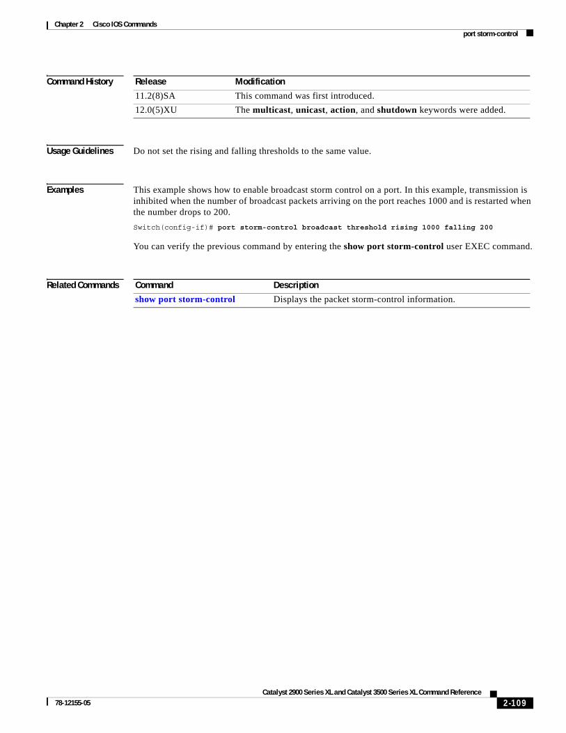
Chapter 2 Cisco IOS Commandsport storm-control
Command History
Usage Guidelines Do not set the rising and falling thresholds to the same value.
Examples This example shows how to enable broadcast storm control on a port. In this example, transmission is inhibited when the number of broadcast packets arriving on the port reaches 1000 and is restarted when the number drops to 200.
Switch(config-if)# port storm-control broadcast threshold rising 1000 falling 200
You can verify the previous command by entering the show port storm-control user EXEC command.
Related Commands
Release Modification
11.2(8)SA This command was first introduced.
12.0(5)XU The multicast, unicast, action, and shutdown keywords were added.
Command Description
show port storm-control Displays the packet storm-control information.
2-109Catalyst 2900 Series XL and Catalyst 3500 Series XL Command Reference
78-12155-05

Chapter 2 Cisco IOS Commandspower inline
power inlineUse the power inline interface configuration command to determine how inline power is applied to the device on the specified Fast Ethernet port of the Catalyst 3524-PWR XL switch. Use the no form of this command to return the setting to its default.
power inline {auto | never}
no power inline
Syntax Description
Defaults Power is applied when a telephone is detected on the port (auto).
Command Modes Interface configuration
Command History
Examples This example shows how to always apply power to the port:
Switch(config-if)# power inline auto
You can verify the previous command by entering the show power inline privileged EXEC command.
Related Commands
auto Automatically detect and power inline devices.
never Never apply inline power.
Release Modification
12.0(5)XU This command was first introduced.
Command Description
show power inline Displays the power status for the specified port or for all ports.
switchport priority extend Determines how the inline device connected to the specified port handles priority traffic received on its incoming port.
switchport voice vlan Configures the voice VLAN on the port.
2-110Catalyst 2900 Series XL and Catalyst 3500 Series XL Command Reference
78-12155-05

Chapter 2 Cisco IOS Commandsprofile
profileUse the profile sequence configuration command to add a Long-Reach Ethernet (LRE) profile to a rate selection sequence. Use the no form of this command to delete a profile from the sequence.
profile profile-name
no profile profile-name
Syntax Description
Defaults The default is LRE-10.
Command Modes Sequence mode
Command History
Usage Guidelines When you add an LRE profile to a sequence, the profile is added to a first-in, first-out (FIFO) queue. Rate selection attempts to establish a link with the first profile in the queue. If the link is not established in that profile, rate selection uses the next profile in the queue.
You cannot add a profile in the middle of the sequence or queue. You cannot add or delete a profile from a system-defined sequence. In order to add a profile to a user-defined sequence in the middle of a sequence, you would first need to delete the most recent profiles.
Although you can delete a profile from a sequence, you cannot change a sequence configuration if it is in use by an interface. You also cannot add or delete a profile from a system-defined sequence.
For a complete list of considerations for using LRE profiles and profile sequences, refer to the “LRE Links and LRE Profiles” section in the Catalyst 2900 Series XL and Catalyst 3500 Series XL Software Configuration Guide.
Examples This example shows how to assign the LRE-4 profile to the SEQ2DOWNSYM sequence:
Switch(config)# lre sequence seq2downSwitch(config-seq)# profile LRE-4Switch(config-seq)#
profile-name Name of the profile. The profile name can be a Cisco-supplied profile or a user-created profile. See the Catalyst 2900 Series XL and Catalyst 3500 Series XL Software Configuration Guide for further details on Cisco-supplied profiles.
Release Modification
12.0(5)WC6 This command was first introduced.
2-111Catalyst 2900 Series XL and Catalyst 3500 Series XL Command Reference
78-12155-05

Chapter 2 Cisco IOS Commandsprofile
Related Commands Command Description
lre rate selection sequence Assigns the rate selection sequence for the entire switch.
lre sequence Defines a new sequence.
rate selection Enables rate selection on a specific port.
rate selection sequence Assigns a rate selection sequence for a specific port.
2-112Catalyst 2900 Series XL and Catalyst 3500 Series XL Command Reference
78-12155-05
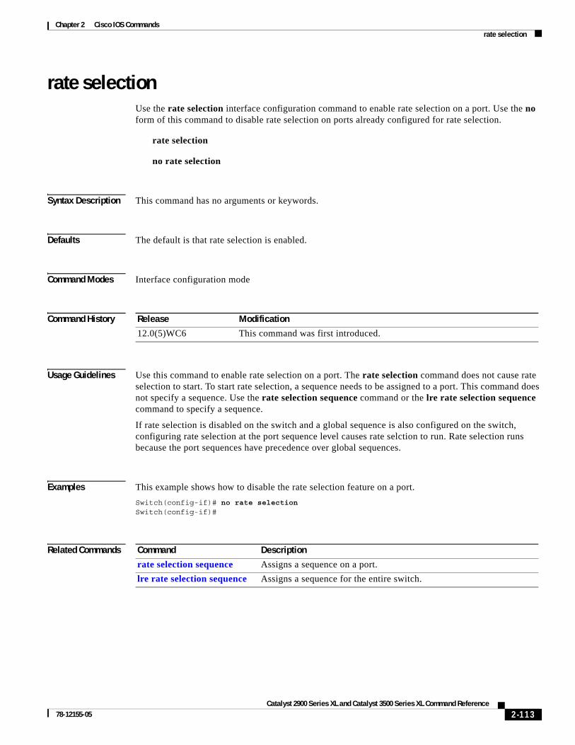
Chapter 2 Cisco IOS Commandsrate selection
rate selectionUse the rate selection interface configuration command to enable rate selection on a port. Use the no form of this command to disable rate selection on ports already configured for rate selection.
rate selection
no rate selection
Syntax Description This command has no arguments or keywords.
Defaults The default is that rate selection is enabled.
Command Modes Interface configuration mode
Command History
Usage Guidelines Use this command to enable rate selection on a port. The rate selection command does not cause rate selection to start. To start rate selection, a sequence needs to be assigned to a port. This command does not specify a sequence. Use the rate selection sequence command or the lre rate selection sequence command to specify a sequence.
If rate selection is disabled on the switch and a global sequence is also configured on the switch, configuring rate selection at the port sequence level causes rate selction to run. Rate selection runs because the port sequences have precedence over global sequences.
Examples This example shows how to disable the rate selection feature on a port.
Switch(config-if)# no rate selectionSwitch(config-if)#
Related Commands
Release Modification
12.0(5)WC6 This command was first introduced.
Command Description
rate selection sequence Assigns a sequence on a port.
lre rate selection sequence Assigns a sequence for the entire switch.
2-113Catalyst 2900 Series XL and Catalyst 3500 Series XL Command Reference
78-12155-05

Chapter 2 Cisco IOS Commandsrate selection profile lock
rate selection profile lockUse the rate selection profile lock interface configuration command to lock a profile in a port that is enabled for rate selection. Use the no form of the command to unlock a profile in a port.
rate selection profile lock
no rate selection profile lock
Syntax Description This command has no arguments or keywords.
Command Modes Interface configuration mode
Command History
Usage Guidelines This command does not enable rate selection. It only has significance when a sequence is assigned to a port.
If rate selection is already converged on the port, this command causes the profile chosen by rate selection to immediately lock. During the lock process, the name of the profile appends to the end of this command. For example, if rate selection converges on LRE-15 and you enter this command, the resulting locked configuration looks like this:
rate selection profile lock LRE-15
If rate selection is not already converged on the port, this command has no immediate effect. However, when rate selection converges for that port, the profile is locked immediately, and the output of the running configuration is saved as in this example.
Examples This example locks a profile to a port that is running rate selection:
Switch(config-if)# rate selection profile lockSwitch(config-if)#
Related Commands
Release Modification
12.0(5)WC6 This command was first introduced.
Command Description
rate selection sequence Assigns a sequence on a port.
lre rate selection sequence Assigns a sequence for the entire switch.
show controllers lre status sequence
Displays information about the profiles and sequences when the sequence parameter is specified.
2-114Catalyst 2900 Series XL and Catalyst 3500 Series XL Command Reference
78-12155-05
Chapter 2 Cisco IOS Commandsrate selection sequence
rate selection sequenceUse the rate selection sequence interface configuration command to assign a sequence to a port and to start rate selection. The no form of the command removes a specific rate selection sequence on a port.
rate selection sequence sequenceName
no rate selection sequence sequenceName
Syntax Description
Command Modes Interface configuration mode
Command History
Usage Guidelines A sequence is a list of profiles. Using this command overrides the default profile of LRE-10 and assigns a sequence of your choice.
When rate selection is enabled, profiles and sequences follow a predefined priority scheme that determines the rate for a port or for the entire switch. These are the priority levels with rate selection enabled, from highest to lowest:
1. Public profile
2. Port sequence
3. Global sequence
4. Port profile
Cisco provides a set of preconfigured sequences, called system-defined sequences. System-defined sequences cannot be modified. Users can create and modify their own sequences by using the lre profile command.
For further details on profiles, sequences and their priority scheme, see Catalyst 2900 Series XL and Catalyst 3500 Series XL Software Configuration Guide.
Examples This example of the rate selection sequence command applies the sequence, CISCO-COMPLETE-SEQUENCE to the port:
Switch(config-if)# rate selection sequence CISCO-COMPLETE-SEQUENCESwitch(config-if)#
sequenceName The name of the sequence being applied to the port. Refer to the Catalyst 2900 Series XL and Catalyst 3500 Series XL Software Configuration Guide for a names of system-supplied sequences.
Release Modification
12.0(5)WC6 This command was first introduced.
2-115Catalyst 2900 Series XL and Catalyst 3500 Series XL Command Reference
78-12155-05

Chapter 2 Cisco IOS Commandsrate selection sequence
Related Commands Command Description
rate selection Enables rate selection on ports already configured for rate selection.
show controllers lre sequence
Displays the list of sequences.
2-116Catalyst 2900 Series XL and Catalyst 3500 Series XL Command Reference
78-12155-05

Chapter 2 Cisco IOS Commandsrcommand
rcommand Use the rcommand user EXEC command to start a Telnet session and to enter commands on a member switch from the command switch. To end the session, enter the exit command.
rcommand {n | commander | mac-address hw-addr}
Syntax Description
Command Modes User EXEC
Command History
Usage Guidelines If the switch is the command switch but the member switch n does not exist, an error message appears. To obtain the switch number, enter the show cluster members privileged EXEC command from the command switch.
You can use this command to access a member switch from the command-switch prompt or to access a command switch from the member-switch prompt.
For Catalyst 2900 XL and Catalyst 3500 XL switches, the Telnet session accesses the member-switch command-line interface (CLI) at the same privilege level as on the command switch. For example, if you enter this command at user level on the cluster command switch, the member switch is accessed at user level. If you use this command on the command switch at privileged level, the command accesses the remote device at privileged level. If you use an intermediate enable-level lower than privileged, access to the member switch is at user level.
For Catalyst 1900 and Catalyst 2820 switches running standard edition software, the Telnet session accesses the menu console (the menu-driven interface) if the command switch is at privilege level 15. If the command switch is at privilege level 1, you are prompted for the password before being able to access the menu console. Command switch privilege levels map to the member switches running standard edition software as follows:
• If the command switch privilege level is from 1 to 14, the member switch is accessed at privilege level 1.
• If the command switch privilege level is 15, the member switch is accessed at privilege level 15.
The Catalyst 1900 and Catalyst 2820 CLI is available only on switches running Enterprise Edition Software.
This command does not work if the vty lines of the command switch have access-class configurations.
You are not prompted for a password because the member switches inherited the password of the command switch when they joined the cluster.
n Provide the number that identifies a cluster member. The range is from 0 to 15.
commander Provide access to the command switch from a member switch.
mac-address hw-addr MAC address of the member switch.
Release Modification
11.2(8)SA6 This command was first introduced.
2-117Catalyst 2900 Series XL and Catalyst 3500 Series XL Command Reference
78-12155-05

Chapter 2 Cisco IOS Commandsrcommand
Examples This example shows how to start a session with member 3. All subsequent commands are directed to member 3 until you enter the exit command or close the session.
Switch> rcommand 3Switch-3> show versionCisco Internet Operating System Software ......Switch-3> exitSwitch>
Related Commands Command Description
show cluster members Displays information about the cluster members.
2-118Catalyst 2900 Series XL and Catalyst 3500 Series XL Command Reference
78-12155-05

Chapter 2 Cisco IOS Commandsreset
resetUse the reset VLAN database command to abandon the proposed VLAN database and to remain in VLAN database mode. This command resets the proposed database to the currently implemented VLAN database on the switch.
reset
Syntax Description This command has no arguments or keywords.
Defaults No default is defined.
Command Modes VLAN database
Command History
Examples This example shows how to abandon the proposed VLAN database and to reset to the VLAN database:
Switch(vlan)# resetSwitch(vlan)#
You can verify the previous command by entering the show changes and show proposed VLAN database commands.
Related Commands
Release Modification
11.2(8)SA4 This command was first introduced.
Command Description
abort Abandons the proposed VLAN database, exits VLAN database mode, and returns to privileged EXEC mode.
apply Implements the proposed VLAN database, increments the database configuration revision number, propagates it throughout the administrative domain, and remains in VLAN database mode.
exit Implements the proposed VLAN database, increments the database configuration number, propagates it throughout the administrative domain, and returns to privileged EXEC mode.
show changes Displays the differences between the VLAN database currently on the switch and the proposed VLAN database.
show proposed Displays the proposed VLAN database or a selected VLAN from it.
shutdown vlan Shuts down (suspends) local traffic on the specified VLAN.
vlan database Enters VLAN database mode from the command-line interface (CLI).
2-119Catalyst 2900 Series XL and Catalyst 3500 Series XL Command Reference
78-12155-05

Chapter 2 Cisco IOS Commandsrmon collection stats
rmon collection statsUse the rmon collection stats interface configuration command to collect Ethernet group statistics. The Ethernet group statistics include utilization statistics about broadcast and multicast packets, and error statistics about Cyclic Redundancy Check (CRC) alignment errors and collisions. Use the no form of this command to return to the default setting.
rmon collection stats index [owner name]
no rmon collection stats index [owner name]
Syntax Description
Defaults The RMON statistics collection is disabled.
Command Modes Interface configuration
Command History
Usage Guidelines The RMON statistics collection command is based on hardware counters.
Examples This example shows how to collect RMON statistics for the owner root on interface fa01:
Switch(config)# interface fa0/1Switch(config-if)# rmon collection stats 2 owner root
You can verify this command by entering the show rmon statistics command in user EXEC mode.
Related Commands
index Remote Network Monitoring (RMON) collection control index. The range is from 1 to 65535.
owner name (Optional) Owner of the RMON collection.
Release Modification
12.0(5)WC1 This command was first introduced.
Command Description
show rmon statistics Displays RMON statistics.
Refer to the Cisco IOS Release 12.0 documentation on Cisco.com for information about this command.
2-120Catalyst 2900 Series XL and Catalyst 3500 Series XL Command Reference
78-12155-05

Chapter 2 Cisco IOS Commandssession
sessionUse the session privileged EXEC command to log into the Asynchronous Transfer Mode (ATM) module operating system and to start a command-line interface (CLI) session. Enter the exit command, or press Ctrl-G to return to the switch command-line interface.
session number
Syntax Description
Command Modes Privileged EXEC
Command History
Examples This example shows how to log in to the ATM module number 1:
Switch# session 1
Related Commands
number Slot number (1 or 2).
Release Modification
11.2(8)SA5 This command was first introduced.
Command Description
exit Exits the session with the ATM module and returns you to the CLI.
2-121Catalyst 2900 Series XL and Catalyst 3500 Series XL Command Reference
78-12155-05

Chapter 2 Cisco IOS Commandsshow cgmp
show cgmpUse the show cgmp user EXEC command to display the state of the Cisco Group Management Protocol (CGMP)-learned multicast groups and routers.
show cgmp [state | holdtime | [vlan vlan-id] | [group [address] | router [address]]] [ | {begin | exclude | include} expression]
Syntax Description
Command Modes User EXEC
Command History
Usage Guidelines This command displays CGMP information about known routers and groups, as well as whether CGMP is enabled, whether Fast Leave is enabled, and the value of the router timeout. If show cgmp is entered with no arguments, all information appears.
Examples This is an example of output from the show cgmp command.
Switch> show cgmp
CGMP is running.CGMP Fast Leave is not running.CGMP Allow reserved address to join GDA.Default router timeout is 300 sec.
state (Optional) Display whether CGMP is enabled or not, whether Fast Leave is enabled or not, and the router port timeout value.
holdtime (Optional) Display the router port timeout value in seconds.
vlan vlan-id (Optional) Limit the display to the specified VLAN. Valid IDs are from 1 to 1001; do not enter leading zeros.
group address (Optional) Display all known multicast groups and the destination ports. Limited to given VLAN if vlan keyword is entered; limited to a specific group if the address variable is entered. The address is the MAC address of the group.
router address (Optional) Display all routers, their ports, and expiration times. Limited to a given VLAN if the vlan keyword entered; limited to a specific router if the address variable is entered. The address is the MAC address of the router.
| begin (Optional) Display begins with the line that matches the expression.
| exclude (Optional) Display excludes lines that match the expression.
| include (Optional) Display includes lines that match the specified expression.
expression Expression in the output to use as a reference point.
Release Modification
11.2(8)SA3 This command was first introduced.
2-122Catalyst 2900 Series XL and Catalyst 3500 Series XL Command Reference
78-12155-05

Chapter 2 Cisco IOS Commandsshow cgmp
vLAN IGMP MAC Address Interfaces------ ----------------- ----------- 1 0100.5e01.0203 Fa0/8 1 0100.5e00.0128 Fa0/8
vLAN IGMP Router Expire Interface------ ----------------- -------- ---------- 1 0060.5cf3.d1b3 197 sec Fa0/8
Related Commands Command Description
cgmp Enables CGMP. Also enables and disables the Fast Leave parameter and sets the router port aging time.
clear cgmp Deletes information that was learned by the switch by using CGMP.
2-123Catalyst 2900 Series XL and Catalyst 3500 Series XL Command Reference
78-12155-05
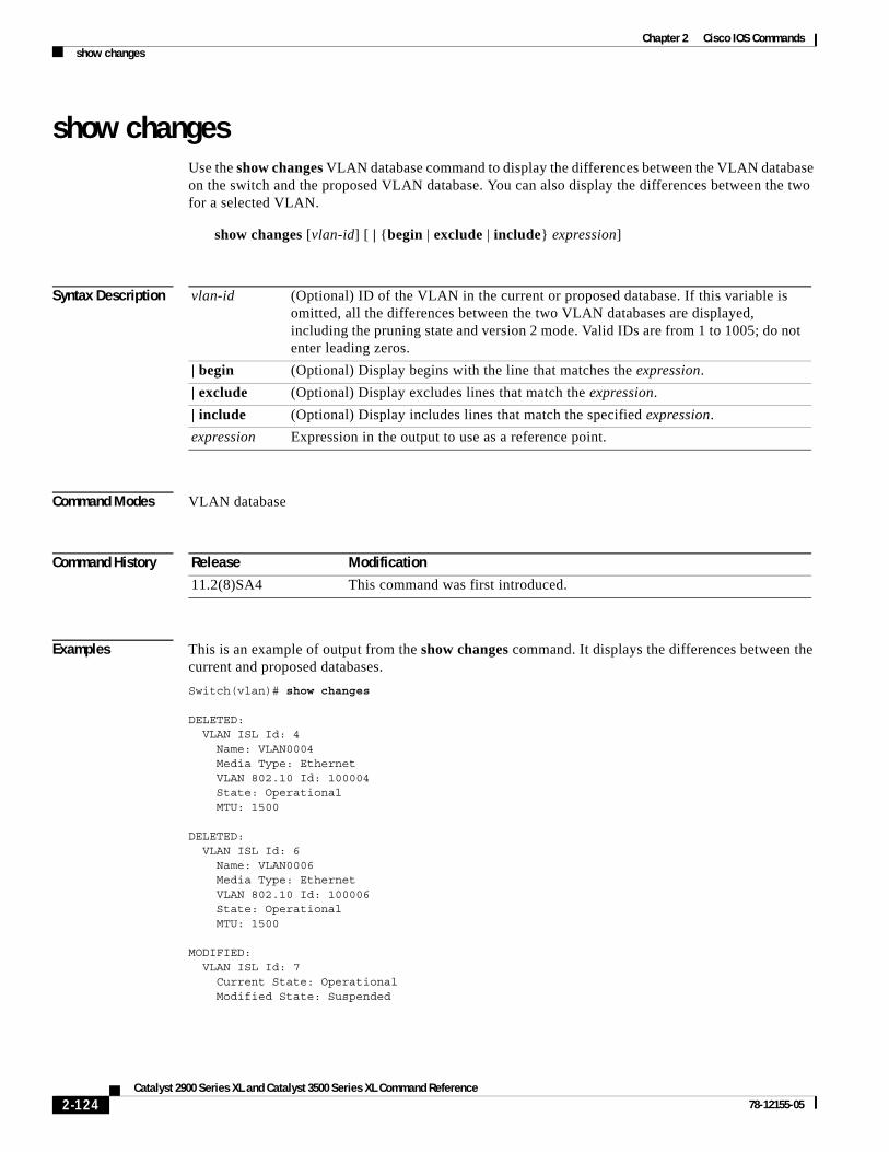
Chapter 2 Cisco IOS Commandsshow changes
show changesUse the show changes VLAN database command to display the differences between the VLAN database on the switch and the proposed VLAN database. You can also display the differences between the two for a selected VLAN.
show changes [vlan-id] [ | {begin | exclude | include} expression]
Syntax Description
Command Modes VLAN database
Command History
Examples This is an example of output from the show changes command. It displays the differences between the current and proposed databases.
Switch(vlan)# show changes
DELETED: VLAN ISL Id: 4 Name: VLAN0004 Media Type: Ethernet VLAN 802.10 Id: 100004 State: Operational MTU: 1500
DELETED: VLAN ISL Id: 6 Name: VLAN0006 Media Type: Ethernet VLAN 802.10 Id: 100006 State: Operational MTU: 1500
MODIFIED: VLAN ISL Id: 7 Current State: Operational Modified State: Suspended
vlan-id (Optional) ID of the VLAN in the current or proposed database. If this variable is omitted, all the differences between the two VLAN databases are displayed, including the pruning state and version 2 mode. Valid IDs are from 1 to 1005; do not enter leading zeros.
| begin (Optional) Display begins with the line that matches the expression.
| exclude (Optional) Display excludes lines that match the expression.
| include (Optional) Display includes lines that match the specified expression.
expression Expression in the output to use as a reference point.
Release Modification
11.2(8)SA4 This command was first introduced.
2-124Catalyst 2900 Series XL and Catalyst 3500 Series XL Command Reference
78-12155-05
Chapter 2 Cisco IOS Commandsshow changes
This is an example of output from the show changes 7 command. It displays the differences between VLAN 7 in the current and proposed database.
Switch(vlan)# show changes 7
MODIFIED: VLAN ISL Id: 7 Current State: Operational Modified State: Suspended
Related Commands Command Description
show current Displays the VLAN database on the switch or a selected VLAN from it.
show proposed Displays the proposed VLAN database or a selected VLAN from it.
2-125Catalyst 2900 Series XL and Catalyst 3500 Series XL Command Reference
78-12155-05
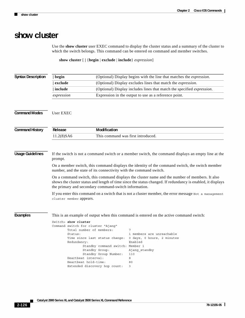
Chapter 2 Cisco IOS Commandsshow cluster
show clusterUse the show cluster user EXEC command to display the cluster status and a summary of the cluster to which the switch belongs. This command can be entered on command and member switches.
show cluster [ | {begin | exclude | include} expression]
Syntax Description
Command Modes User EXEC
Command History
Usage Guidelines If the switch is not a command switch or a member switch, the command displays an empty line at the prompt.
On a member switch, this command displays the identity of the command switch, the switch member number, and the state of its connectivity with the command switch.
On a command switch, this command displays the cluster name and the number of members. It also shows the cluster status and length of time since the status changed. If redundancy is enabled, it displays the primary and secondary command-switch information.
If you enter this command on a switch that is not a cluster member, the error message Not a management cluster member appears.
Examples This is an example of output when this command is entered on the active command switch:
Switch> show clusterCommand switch for cluster "Ajang" Total number of members: 7 Status: 1 members are unreachable Time since last status change: 0 days, 0 hours, 2 minutes Redundancy: Enabled Standby command switch: Member 1 Standby Group: Ajang_standby Standby Group Number: 110 Heartbeat interval: 8 Heartbeat hold-time: 80 Extended discovery hop count: 3
| begin (Optional) Display begins with the line that matches the expression.
| exclude (Optional) Display excludes lines that match the expression.
| include (Optional) Display includes lines that match the specified expression.
expression Expression in the output to use as a reference point.
Release Modification
11.2(8)SA6 This command was first introduced.
2-126Catalyst 2900 Series XL and Catalyst 3500 Series XL Command Reference
78-12155-05

Chapter 2 Cisco IOS Commandsshow cluster
This is an example of output when this command is entered on a member switch:
Switch1> show clusterMember switch for cluster "mcluster" Member number: 3 Management IP address: 192.192.192.192 Command switch mac address: 0000.0c07.ac14 Heartbeat interval: 8 Heartbeat hold-time: 80
This is an example of output when this command is entered on a member switch that is configured as the standby command switch:
Switch> show clusterMember switch for cluster "mcluster" Member number: 3 (Standby command switch) Management IP address: 192.192.192.192 Command switch mac address: 0000.0c07.ac14 Heartbeat interval: 8 Heartbeat hold-time: 80
This is an example of output when this command is entered on the command switch that has lost connectivity with member 1:
3524-24> show clusterCommand switch for cluster "Ajang" Total number of members: 7 Status: 1 members are unreachable Time since last status change: 0 days, 0 hours, 5 minutes Redundancy: Disabled Heartbeat interval: 8 Heartbeat hold-time: 80 Extended discovery hop count: 3
This is an example of output when this command is entered on a member switch that has lost connectivity with the command switch:
3512-12> show clusterMember switch for cluster "mcluster" Member number: <UNKNOWN> Management IP address: 192.192.192.192 Command switch mac address: 0000.0c07.ac14 Heartbeat interval: 8 Heartbeat hold-time: 80
Related Commands Command Description
cluster enable Enables a command-capable switch as the cluster command switch, assigns a cluster name, and optionally assigns a member number to it.
show cluster candidates Displays a list of candidate switches.
show cluster members Displays information about the cluster members.
2-127Catalyst 2900 Series XL and Catalyst 3500 Series XL Command Reference
78-12155-05

Chapter 2 Cisco IOS Commandsshow cluster candidates
show cluster candidatesUse the show cluster candidates user EXEC command on the command switch to display a list of candidate switches.
show cluster candidates [mac-address H.H.H. | detail] [ | {begin | exclude | include} expression]
Syntax Description
Command Modes User EXEC
Command History
Usage Guidelines Enter this command only on a command switch.
If the switch is not a command switch, the command line displays an empty line at the prompt.
The SN in the display means switch member number. If E appears in the SN column, it means that the switch is discovered through extended discovery. If E does not appear in the SN column, it means that the switch member number of the upstream neighbor of the candidate switch. The hop count is the number of devices that the candidate is from the command switch.
Examples This is an example of output from the show cluster candidates command.
Switch> show cluster candidates
|---Upstream---|MAC Address Name Device Type PortIf FEC Hops SN PortIf FEC00d0.7961.c4c0 3512-12 WS-C3512-XL Fa0/3 1 0 Fa0/13 00d0.bbf5.e900 ldf-dist-128 WS-C3524-XL Fa0/7 1 0 Fa0/24 00e0.1e7e.be80 1900_Switch 1900 3 0 1 0 Fa0/11 00e0.1e9f.7a00 2924-24 WS-C2924-XL Fa0/5 1 0 Fa0/3 00e0.1e9f.8c00 2912-12-2 WS-C2912-XL Fa0/4 1 0 Fa0/7 00e0.1e9f.8c40 2912-12-1 WS-C2912-XL Fa0/1 1 0 Fa0/9 0050.2e4a.9fb0 murali-132 WS-C3508-XL E0050.354e.7cd0 murali-134 WS-C2924-XL E
mac-address H.H.H. (Optional) MAC address of the cluster candidate.
detail (Optional) Display detailed information for all candidates.
| begin (Optional) Display begins with the line that matches the expression.
| exclude (Optional) Display excludes lines that match the expression.
| include (Optional) Display includes lines that match the specified expression.
expression Expression in the output to use as a reference point.
Release Modification
11.2(8)SA6 This command was first introduced.
12.0(5)XU The detail keyword was added.
2-128Catalyst 2900 Series XL and Catalyst 3500 Series XL Command Reference
78-12155-05

Chapter 2 Cisco IOS Commandsshow cluster candidates
This is an example of output from the show cluster candidates command that uses the MAC address of a member switch directly connected to the command switch:
Switch> show cluster candidates mac-address 00d0.7961.c4c0Device '3512-12' with mac address number 00d0.7961.c4c0 Device type: cisco WS-C3512-XL Upstream MAC address: 00d0.796d.2f00 (Cluster Member 0) Local port: Fa0/3 FEC number: Upstream port: Fa0/13 FEC Number: Hops from cluster edge: 1 Hops from command device: 1
This is an example of output from the show cluster candidates command that uses the MAC address of a member switch three hops from the cluster edge:
Switch> show cluster candidates mac-address 0010.7bb6.1cc0Device '2912MF' with mac address number 0010.7bb6.1cc0 Device type: cisco WS-C2912MF-XL Upstream MAC address: 0010.7bb6.1cd4 Local port: Fa2/1 FEC number: Upstream port: Fa0/24 FEC Number: Hops from cluster edge: 3 Hops from command device: -
This is an example of output from the show cluster candidates detail command:
Switch> show cluster candidates detailDevice '3512-12' with mac address number 00d0.7961.c4c0 Device type: cisco WS-C3512-XL Upstream MAC address: 00d0.796d.2f00 (Cluster Member 1) Local port: Fa0/3 FEC number: Upstream port: Fa0/13 FEC Number: Hops from cluster edge: 1 Hops from command device: 2
Device '1900_Switch' with mac address number 00e0.1e7e.be80 Device type: cisco 1900 Upstream MAC address: 00d0.796d.2f00 (Cluster Member 2) Local port: 3 FEC number: 0 Upstream port: Fa0/11 FEC Number: Hops from cluster edge: 1 Hops from command device: 2Device '2924-24' with mac address number 00e0.1e9f.7a00 Device type: cisco WS-C2924-XL Upstream MAC address: 00d0.796d.2f00 (Cluster Member 3) Local port: Fa0/5 FEC number: Upstream port: Fa0/3 FEC Number: Hops from cluster edge: 1 Hops from command device: 2
Related Commands Command Description
show cluster Displays the cluster status and a summary of the cluster to which the switch belongs.
show cluster members Displays information about the cluster members.
2-129Catalyst 2900 Series XL and Catalyst 3500 Series XL Command Reference
78-12155-05

Chapter 2 Cisco IOS Commandsshow cluster members
show cluster members Use the show cluster members user EXEC command on the command switch to display information about the cluster members.
show cluster members [n | detail] [ | {begin | exclude | include} expression]
Syntax Description
Command Modes User EXEC
Command History
Usage Guidelines You should enter this command only on a command switch.
If the cluster has no members, an empty line appears at the prompt.
Examples This is an example of output from the show cluster members command. The SN in the display means switch number.
Switch> show cluster members
|---Upstream---|SN MAC Address Name PortIf FEC Hops SN PortIf FEC State0 00d0.796d.2f00 3524-24 0 Up (Cmdr)1 00d0.7960.66c0 255 Down2 00e0.1e9f.8c00 2912-12-2 Fa0/4 1 0 Fa0/7 Up (Standby)3 00e0.1e9f.7a00 2924-24 Fa0/5 1 0 Fa0/3 Up4 00d0.bbf5.e900 ldf-dist-128 Fa0/7 1 0 Fa0/24 Up5 00d0.7961.c4c0 3512-12 Fa0/3 1 0 Fa0/13 Up6 00e0.1e9f.8c40 2912-12-1 Fa0/1 1 0 Fa0/9 Up7 00e0.1e7e.be80 1900_Switch 3 0 1 0 Fa0/11 Up8 00e0.1e9f.8300 2924M Fa0/11 2 5 Fa0/12 Up9 0010.7bb6.1cc0 2912MF Fa2/1 3 8 Fa0/24 Up10 00e0.1e87.2140 2820-01 24 0 4 9 Fa2/3 Up
n (Optional) Number that identifies a cluster member. The range is from 0 to 15.
detail (Optional) Display detailed information for all cluster members.
| begin (Optional) Display begins with the line that matches the expression.
| exclude (Optional) Display excludes lines that match the expression.
| include (Optional) Display includes lines that match the specified expression.
expression Expression in the output to use as a reference point.
Release Modification
11.2(8)SA6 This command was first introduced.
12.0(5)XU The detail keyword was added.
2-130Catalyst 2900 Series XL and Catalyst 3500 Series XL Command Reference
78-12155-05

Chapter 2 Cisco IOS Commandsshow cluster members
This is an example of output from the show cluster members for cluster member 3:
Switch> show cluster members 3Device '2924-24' with member number 3 Device type: cisco WS-C2924M-XL MAC address: 00e0.1e9f.9440 Upstream MAC address: 00d0.796d.2e00 (Cluster member 0) Local port: Fa0/18 FEC number: Upstream port: Fa0/20 FEC Number: Hops from command device: 1
This is an example of output from the show cluster members detail command:
Switch> show cluster members detailDevice '3524-24' with member number 0 (Command Switch) Device type: cisco WS-C3524-XL MAC address: 00d0.7964.1f00 Upstream MAC address: Local port: FEC number: Upstream port: FEC Number: Hops from command device: 0'Unknown'device with member number 1 Device type: MAC address: Upstream MAC address: Local port: FEC number: Upstream port: FEC Number: Hops from command device: 255Device '2912-12-2' with member number 2 Device type: cisco WS-C3548-XL MAC address: 00d0.5868.f5c0 Upstream MAC address: 00d0.7964.1f00 (Cluster member 0) Local port: Fa0/7 FEC number: 1 Upstream port: Fa0/6 FEC Number: Hops from command device: 1Device '2924-24' with member number 3 Device type: cisco WS-C3508G-XL MAC address: 00d0.7968.5380 Upstream MAC address: 00d0.7964.1f00 (Cluster member 0) Local port: Gi0/6 FEC number: Upstream port: Gi0/1 FEC Number: Hops from command device: 1
Related Commands Command Description
show cluster Displays the cluster status and a summary of the cluster to which the switch belongs.
show cluster candidates Displays a list of candidate switches.
2-131Catalyst 2900 Series XL and Catalyst 3500 Series XL Command Reference
78-12155-05

Chapter 2 Cisco IOS Commandsshow controllers ethernet-controller
show controllers ethernet-controllerUse the show controllers ethernet-controller privileged EXEC command to display the Ethernet link send and receive statistics on a Fast Ethernet or Long-Reach Ethernet (LRE) port.
show controllers ethernet-controller [interface-id] [ | {begin | exclude | include} expression]
Syntax Description
Command Modes Privileged EXEC
Command History
Usage Guidelines Using the show controllers ethernet-controller command without specifying a Fast Ethernet or LRE port displays the Ethernet link statistics of all Ethernet ports on the switch and on the connected customer premises equipment (CPE) devices. The output shows the internal switch statistics, the statistics collected by the LRE interface on the switch, and the statistics collected by the LRE interface on the CPE device.
The CPE Ethernet link on a switch LRE port is the connection between the Cisco LRE CPE and the remote Ethernet device (such as a PC) connected to it. It is not the link between the switch LRE port and the LRE CPE.
Examples This is an example of output from the show controllers ethernet-controller command on Fast Ethernet port 1:
Switch# show controllers ethernet-controller fa0/1
Transmit Receive 877634 Bytes 8834435 Bytes 3853 Unicast frames 5212 Unicast frames 606 Multicast frames 20600 Multicast frames 3496 Broadcast frames 32756 Broadcast frames 0 Discarded frames 0 No bandwidth frames 0 Too old frames 0 No buffers frames 0 Deferred frames 10697 No dest, unicast 0 1 collision frames 42555 No dest, multicast 0 2 collision frames 0 No dest, broadcast 0 3 collision frames 0 Alignment errors 0 4 collision frames 0 FCS errors 0 5 collision frames 0 Collision fragments 0 6 collision frames
interface-id (Optional) ID of the Fast Ethernet or LRE port.
| begin (Optional) Display begins with the line that matches the expression.
| exclude (Optional) Display excludes lines that match the expression.
| include (Optional) Display includes lines that match the specified expression.
expression Expression in the output to use as a reference point.
Release Modification
12.0(5)WC1 This command was first introduced.
2-132Catalyst 2900 Series XL and Catalyst 3500 Series XL Command Reference
78-12155-05

Chapter 2 Cisco IOS Commandsshow controllers ethernet-controller
0 7 collision frames 0 Undersize frames 0 8 collision frames 33602 Minimum size frames 0 9 collision frames 75929 65 to 127 byte frames 0 10 collision frames 760 128 to 255 byte frames 0 11 collision frames 1527 256 to 511 byte frames 0 12 collision frames 2 512 to 1023 byte frames 0 13 collision frames 0 1024 to 1518 byte frames 0 14 collision frames 0 Oversize frames 0 15 collision frames 0 Excessive collisions 0 Late collisions
This is an example of output from the show controllers ethernet-controller command to display the Ethernet link statistics between the CPE device and the PC when the CPE device is connected to switch LRE port 2:
Switch# show controllers eth lo0/2
Transmit Receive 64 Bytes 64 Bytes 1 Unicast frames 1 Unicast frames 0 Multicast frames 0 Multicast frames 0 Broadcast frames 0 Broadcast frames 0 Discarded frames 0 No bandwidth frames 0 Too old frames 0 No buffers frames 0 Deferred frames 0 No dest, unicast 0 1 collision frames 0 No dest, multicast 0 2 collision frames 0 No dest, broadcast 0 3 collision frames 0 Alignment errors 0 4 collision frames 0 FCS errors 0 5 collision frames 0 Collision fragments 0 6 collision frames 0 7 collision frames 0 Undersize frames 0 8 collision frames 1 Minimum size frames 0 9 collision frames 0 65 to 127 byte frames 0 10 collision frames 0 128 to 255 byte frames 0 11 collision frames 0 256 to 511 byte frames 0 12 collision frames 0 512 to 1023 byte frames 0 13 collision frames 0 1024 to 1518 byte frames 0 14 collision frames 0 Oversize frames 0 15 collision frames 0 Excessive collisions 0 Late collisions
LRE Enet Stats on Switch:
0 Bytes 0 Bytes 0 Frames 0 Frames 0 Broadcast frames 0 Pause frames 0 Pause frames 65 1 collision frames 520 Alignment errors 0 Multiple collisions 0 Collisions and Runts 0 Late collisions 0 Oversize frames 0 Excessive collisions 0 FCS errors 0 Deferred frames 0 Carrier sense errors
LRE Enet Stats on CPE:
0 Bytes 0 Bytes 0 Frames 0 Frames 0 Broadcast frames 0 Pause frames 0 Pause frames 24 1 collision frames 150 Alignment errors
2-133Catalyst 2900 Series XL and Catalyst 3500 Series XL Command Reference
78-12155-05

Chapter 2 Cisco IOS Commandsshow controllers ethernet-controller
0 Multiple collisions 0 Collisions and Runts 0 Late collisions 0 Oversize frames 0 Excessive collisions 0 FCS errors 0 Deferred frames 0 Carrier sense errors
Related Commands Command Description
clear controllers ethernet-controller
Deletes the Ethernet link transmit and receive statistics on a Fast Ethernet or LRE switch port.
2-134Catalyst 2900 Series XL and Catalyst 3500 Series XL Command Reference
78-12155-05

Chapter 2 Cisco IOS Commandsshow controllers lre cpe info
show controllers lre cpe infoUse the show controllers lre cpe info privileged EXEC command to display the model numbers of the Long-Reach Ethernet (LRE) customer premises equipment (CPE) devices connected to the LRE switch. This command also shows whether or not the connected CPE devices meet the minimum requirements to be managed by the LRE switch.
show controllers lre cpe info [interface-id] [ | {begin | exclude | include} expression]
Syntax Description
Command Modes Privileged EXEC
Command History
Usage Guidelines The status of a connected LRE CPE device can be certified or not certified. A pass status means the CPE device meets the minimum requirements (such as having a certain CPE patch version) to be managed by the LRE switch. A failed status means that it does not.
Using the show controllers lre cpe info command without specifying a switch LRE port displays the model numbers and status of all connected CPE devices.
Examples This is an example of output from the show controllers lre cpe info command:
Switch# show controllers lre cpe info
Port CPE Model Status Family------ ------------ --------------- -------Lo0/1 CISCO575-LRE CERTIFIED CISCO575-LRELo0/2 NA NO LINK NALo0/3 NA NO LINK NALo0/4 NA NO LINK NALo0/5 NA NO LINK NALo0/6 CISCO575-LRE CERTIFIED CISCO575-LRELo0/7 NA NO LINK NALo0/8 NA NO LINK NALo0/9 NA NO LINK NALo0/10 NA NO LINK NALo0/11 NA NO LINK NALo0/12 NA NO LINK NALo0/13 NA NO LINK NALo0/14 NA NO LINK NALo0/15 NA NO LINK NA
interface-id (Optional) ID of the switch LRE port.
| begin (Optional) Display begins with the line that matches the expression.
| exclude (Optional) Display excludes lines that match the expression.
| include (Optional) Display includes lines that match the specified expression.
expression Expression in the output to use as a reference point.
Release Modification
12.0(5)WC4 This command was first introduced.
2-135Catalyst 2900 Series XL and Catalyst 3500 Series XL Command Reference
78-12155-05

Chapter 2 Cisco IOS Commandsshow controllers lre cpe info
Lo0/16 NA NO LINK NALo0/17 NA NO LINK NALo0/18 NA NO LINK NALo0/19 NA NO LINK NALo0/20 NA NO LINK NALo0/21 NA NO LINK NALo0/22 NA NO LINK NALo0/23 NA NO LINK NALo0/24 NA NO LINK NA
Related Commands Command Description
debug lre Enables debugging of LRE-related events.
show controllers lre version Displays the version number of the hardware, software, and patch software components of the switch LRE interface and the CPE LRE interface.
show controllers lre version mfg Displays the revision and serial numbers of the connected Cisco LRE CPE board, assembly, and system.
2-136Catalyst 2900 Series XL and Catalyst 3500 Series XL Command Reference
78-12155-05

Chapter 2 Cisco IOS Commandsshow controllers lre cpe protected
show controllers lre cpe protectedUse the show controllers lre cpe protected privileged EXEC command to display and identify Cisco 585 LRE customer premises equipmement (CPE) Ethernet ports that are configured as protected.
show controllers lre cpe protected [interface-id] [ | {begin | exclude | include} expression]
Syntax Description
Command Modes Privileged EXEC
Command History
Usage Guidelines Using the show controllers lre cpe protected command without specifying an LRE switch port displays the version numbers of all switch LRE interfaces. Cisco 575 LRE CPE devices display a protected filed output of NA.
Examples This is an example of output that shows the CPE protected information for LRE interface lo0/1:
Switch# show controllers lre cpe protected lo0/9Interface Port Protected--------- ---- --------- Lo0/9 1 true Lo0/9 2 true Lo0/9 3 true Lo0/9 4 true
This is an example of output that shows the CPE protected information for all switch LRE interfaces:
Switch# show controllers lre cpe protectedInterface Port Protected--------- ---- --------- Lo0/1 1 NA Lo0/2 1 NA Lo0/3 1 NA Lo0/4 1 NA Lo0/5 1 NA Lo0/6 1 NA Lo0/7 1 NA Lo0/8 1 false Lo0/8 2 false Lo0/8 3 false
interface-id (Optional) ID of the switch Long-Reach Ethernet (LRE) port.
| begin (Optional) Display begins with the line that matches the specified expression.
| exclude (Optional) Display excludes lines that match the specified expression.
| include (Optional) Display includes lines that match the specified expression.
expression Expression in the output to use as a reference point.
Release Modification
12.1(11)YJ This command was first introduced.
2-137Catalyst 2900 Series XL and Catalyst 3500 Series XL Command Reference
78-12155-05

Chapter 2 Cisco IOS Commandsshow controllers lre cpe protected
Lo0/8 4 false Lo0/9 1 true Lo0/9 2 true Lo0/9 3 true Lo0/9 4 true Lo0/10 1 NA Lo0/11 1 NA Lo0/12 1 NA Lo0/13 1 NA Lo0/14 1 NA
Interface Port Protected--------- ---- --------- Lo0/15 1 NA Lo0/16 1 NA Lo0/17 1 NA Lo0/18 1 NA Lo0/19 1 NA Lo0/20 1 NA Lo0/21 1 NA Lo0/22 1 NA Lo0/23 1 NA Lo0/24 1 NA
Related Commands Command Description
cpe protected Restricts data traffic to individual ports on Cisco 585 LRE CPE ports.
2-138Catalyst 2900 Series XL and Catalyst 3500 Series XL Command Reference
78-12155-05

Chapter 2 Cisco IOS Commandsshow controllers lre interface-id actual
show controllers lre interface-id actualUse the show controllers lre interface-id actual privileged EXEC command to display the actual values of the Long-Reach Ethernet (LRE) link on a specific switch LRE port.
show controllers lre interface-id actual [dsrserrs | usrserrs | txpower | rxpower | snr | link] [ | {begin | exclude | include} expression]
Syntax Description
Command Modes Privileged EXEC
Command History
Usage Guidelines Use the signal-to-noise ratio (SNR) and Reed-Solomon error information to measure the quality of the LRE link. The SNR represents the amount of increased received signal power (in decibels) relative to the noise power level that the switch is designed to tolerate without disconnecting from the CPE device. The higher the ratio, the more resilient is the link.
The Reed-Solomon errors show the number of errors detected and corrected in the data being received on and transmitted from the switch LRE ports. Reed-Solomon errors are the result of noise exceeding the noise margin. For short bursts of noise (such as motor startup or power surges), the interleaver prevents the loss of Ethernet data packets. In this case, the number of Reed-Solomon errors exceeds the number of Ethernet CRC errors.
The remote transmit power rates from the connected CPE devices might be different, depending on the length of the cable between the switch and the CPE device. A longer cable typically causes the CPE device to send a higher signal to overcome the loss due to distance.
interface-id ID of the switch LRE port.
actual Display the LRE port current status, which might not be the same as the administratively configured settings.
dsrserrs Display the downstream Reed-Solomon errors on the LRE port.
usrserrs Display the upstream Reed-Solomon errors on the LRE port.
txpower Display the remote transmit power (dBm/Hz) on the LRE port.
rxpower Display the local receive power (dBm/Hz) on the customer premises equipment (CPE) port.
snr Display the signal-to-noise ratio (SNR) ratio on the LRE port.
link Display the LRE link status of the LRE port.
| begin (Optional) Display begins with the line that matches the expression.
| exclude (Optional) Display excludes lines that match the expression.
| include (Optional) Display includes lines that match the specified expression.
expression Expression in the output to use as a reference point.
Release Modification
12.0(5)WC1 This command was first introduced.
2-139Catalyst 2900 Series XL and Catalyst 3500 Series XL Command Reference
78-12155-05

Chapter 2 Cisco IOS Commandsshow controllers lre interface-id actual
The local receive power actually displays the switch adjustment to the incoming power level. These numbers might be different from LRE port to LRE port, as the length of the cables to the CPE devices might be different.
If the SNR is too low for the environment but the link still establishes, the Reed-Solomon error rate will be high, and there might be link instability (as shown by the number of Fail events counted). If the network is being used for data only, a high incidence of Ethernet Frame Check Sequence (FCS) errors or micro-interruptions might be tolerable.
For more information about what can affect the LRE link and for the minimum required SNR ratios, refer to the “LRE Links and LRE Profiles” section in the Catalyst 2900 Series XL and Catalyst 3500 Series XL Software Configuration Guide.
Examples This is an example of output from the show controllers lre interface-id actual dsrserrs command on switch LRE port 1:
Switch# show controller lre lo0/2 actual dsrserrs0Switch# show controller lre lo0/2 actual linkUPSwitch# show controller lre lo0/2 actual rxpower26.0Switch# show controller lre lo0/2 actual snr27Switch#s how controller lre lo0/2 actual txpower-89.7Switch# show controller lre lo0/2 actual usrserrs0
This is an example of output from the show controllers lre interface-id actual link command on switch LRE port 1:
Switch# show controllers lre lo0/1 actual linkDOWN
Related Commands Command Description
show controllers lre interface-id admin
Displays the administrative settings of the LRE link on a specific switch LRE port.
show controllers lre status Displays the LRE link status of a specific switch LRE port.
2-140Catalyst 2900 Series XL and Catalyst 3500 Series XL Command Reference
78-12155-05

Chapter 2 Cisco IOS Commandsshow controllers lre interface-id admin
show controllers lre interface-id adminUse the show controllers lre interface-id admin privileged EXEC command to display the administrative settings of the Long-Reach Ethernet (LRE) link on a specific switch LRE port.
show controllers lre interface-id admin [dsrate | usrate] [| {begin | exclude | include} expression]
Syntax Description
Command Modes Privileged EXEC
Command History
Usage Guidelines This command displays the private profile settings of a switch LRE port, even though they might not be active if a global profile is configured on the switch.
The upstream and downstream rates are defined by the profile on the switch LRE port. To change these rates, assign a different profile to the switch LRE port. For information about the LRE profiles, refer to the Catalyst 2900 Series XL and Catalyst 3500 Series XL Software Configuration Guide.
Examples This is an example of output from the show controllers lre interface-id admin dsrate and show controllers lre interface-id admin usrate commands on switch LRE ports 1 and 2:
Switch# show controller lre lo0/1 admin usrate18.750Switch#
Switch# show controller lre lo0/1 admin dsrate16.667Switch#
Switch# show controller lre lo0/2 admin usrate12.500Switch#
interface-id ID of the switch LRE port.
admin Display the administrative settings, which might not be the same as the actual values.
dsrate Display the downstream rate (Mbps) of the LRE link.
usrate Display the upstream rate (Mbps) of the LRE link.
| begin (Optional) Display begins with the line that matches the expression.
| exclude (Optional) Display excludes lines that match the expression.
| include (Optional) Display includes lines that match the specified expression.
expression Expression in the output to use as a reference point.
Release Modification
12.0(5)WC1 This command was first introduced.
2-141Catalyst 2900 Series XL and Catalyst 3500 Series XL Command Reference
78-12155-05
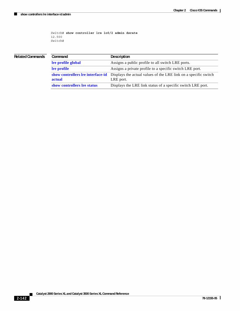
Chapter 2 Cisco IOS Commandsshow controllers lre interface-id admin
Switch# show controller lre lo0/2 admin dsrate12.500Switch#
Related Commands Command Description
lre profile global Assigns a public profile to all switch LRE ports.
lre profile Assigns a private profile to a specific switch LRE port.
show controllers lre interface-id actual
Displays the actual values of the LRE link on a specific switch LRE port.
show controllers lre status Displays the LRE link status of a specific switch LRE port.
2-142Catalyst 2900 Series XL and Catalyst 3500 Series XL Command Reference
78-12155-05
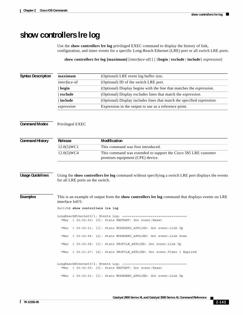
Chapter 2 Cisco IOS Commandsshow controllers lre log
show controllers lre logUse the show controllers lre log privileged EXEC command to display the history of link, configuration, and timer events for a specific Long-Reach Ethernet (LRE) port or all switch LRE ports.
show controllers lre log [maximum] [interface-id] [ | {begin | exclude | include} expression]
Syntax Description
Command Modes Privileged EXEC
Command History
Usage Guidelines Using the show controllers lre log command without specifying a switch LRE port displays the events for all LRE ports on the switch.
Examples This is an example of output from the show controllers lre log command that displays events on LRE interface lo0/5:
Switch# show controllers lre log
LongReachEthernet0/1: Events Log: ================================== *Mar 1 00:00:50: [0]: State RESTART: Got event:Reset
*Mar 1 00:00:51: [1]: State MODEZERO_APPLIED: Got event:Link Up
*Mar 1 00:00:56: [2]: State MODEZERO_APPLIED: Got event:Link Down
*Mar 1 00:00:58: [3]: State PROFILE_APPLIED: Got event:Link Up
*Mar 1 00:01:27: [4]: State PROFILE_APPLIED: Got event:Timer 1 Expired
LongReachEthernet0/2: Events Log: ================================== *Mar 1 00:00:50: [0]: State RESTART: Got event:Reset
*Mar 1 00:00:51: [1]: State MODEZERO_APPLIED: Got event:Link Up
maximum (Optional) LRE event log buffer size.
interface-id (Optional) ID of the switch LRE port.
| begin (Optional) Display begins with the line that matches the expression.
| exclude (Optional) Display excludes lines that match the expression.
| include (Optional) Display includes lines that match the specified expression.
expression Expression in the output to use as a reference point.
Release Modification
12.0(5)WC1 This command was first introduced.
12.0(5)WC4 This command was extended to support the Cisco 585 LRE customer premises equipment (CPE) device.
2-143Catalyst 2900 Series XL and Catalyst 3500 Series XL Command Reference
78-12155-05
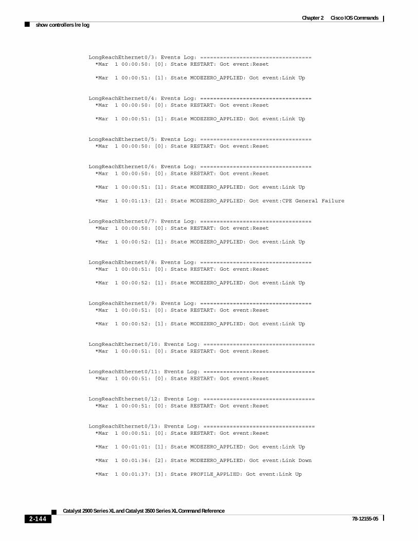
Chapter 2 Cisco IOS Commandsshow controllers lre log
LongReachEthernet0/3: Events Log: ================================== *Mar 1 00:00:50: [0]: State RESTART: Got event:Reset
*Mar 1 00:00:51: [1]: State MODEZERO_APPLIED: Got event:Link Up LongReachEthernet0/4: Events Log: ================================== *Mar 1 00:00:50: [0]: State RESTART: Got event:Reset *Mar 1 00:00:51: [1]: State MODEZERO_APPLIED: Got event:Link Up LongReachEthernet0/5: Events Log: ================================== *Mar 1 00:00:50: [0]: State RESTART: Got event:Reset LongReachEthernet0/6: Events Log: ================================== *Mar 1 00:00:50: [0]: State RESTART: Got event:Reset *Mar 1 00:00:51: [1]: State MODEZERO_APPLIED: Got event:Link Up *Mar 1 00:01:13: [2]: State MODEZERO_APPLIED: Got event:CPE General Failure LongReachEthernet0/7: Events Log: ================================== *Mar 1 00:00:50: [0]: State RESTART: Got event:Reset *Mar 1 00:00:52: [1]: State MODEZERO_APPLIED: Got event:Link Up LongReachEthernet0/8: Events Log: ================================== *Mar 1 00:00:51: [0]: State RESTART: Got event:Reset *Mar 1 00:00:52: [1]: State MODEZERO_APPLIED: Got event:Link Up LongReachEthernet0/9: Events Log: ================================== *Mar 1 00:00:51: [0]: State RESTART: Got event:Reset *Mar 1 00:00:52: [1]: State MODEZERO_APPLIED: Got event:Link Up LongReachEthernet0/10: Events Log: ================================== *Mar 1 00:00:51: [0]: State RESTART: Got event:Reset LongReachEthernet0/11: Events Log: ================================== *Mar 1 00:00:51: [0]: State RESTART: Got event:Reset LongReachEthernet0/12: Events Log: ================================== *Mar 1 00:00:51: [0]: State RESTART: Got event:Reset LongReachEthernet0/13: Events Log: ================================== *Mar 1 00:00:51: [0]: State RESTART: Got event:Reset *Mar 1 00:01:01: [1]: State MODEZERO_APPLIED: Got event:Link Up *Mar 1 00:01:36: [2]: State MODEZERO_APPLIED: Got event:Link Down *Mar 1 00:01:37: [3]: State PROFILE_APPLIED: Got event:Link Up
2-144Catalyst 2900 Series XL and Catalyst 3500 Series XL Command Reference
78-12155-05
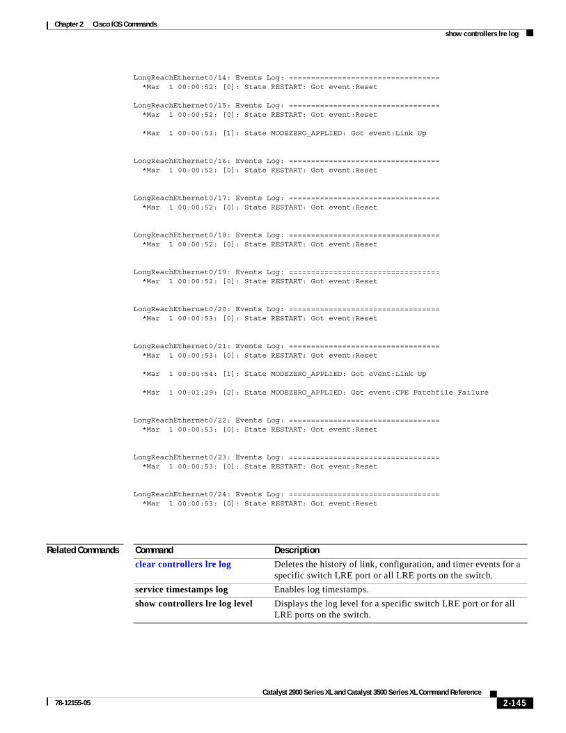
Chapter 2 Cisco IOS Commandsshow controllers lre log
LongReachEthernet0/14: Events Log: ================================== *Mar 1 00:00:52: [0]: State RESTART: Got event:Reset LongReachEthernet0/15: Events Log: ================================== *Mar 1 00:00:52: [0]: State RESTART: Got event:Reset *Mar 1 00:00:53: [1]: State MODEZERO_APPLIED: Got event:Link Up LongReachEthernet0/16: Events Log: ================================== *Mar 1 00:00:52: [0]: State RESTART: Got event:Reset LongReachEthernet0/17: Events Log: ================================== *Mar 1 00:00:52: [0]: State RESTART: Got event:Reset LongReachEthernet0/18: Events Log: ================================== *Mar 1 00:00:52: [0]: State RESTART: Got event:Reset LongReachEthernet0/19: Events Log: ================================== *Mar 1 00:00:52: [0]: State RESTART: Got event:Reset LongReachEthernet0/20: Events Log: ================================== *Mar 1 00:00:53: [0]: State RESTART: Got event:Reset LongReachEthernet0/21: Events Log: ================================== *Mar 1 00:00:53: [0]: State RESTART: Got event:Reset *Mar 1 00:00:54: [1]: State MODEZERO_APPLIED: Got event:Link Up *Mar 1 00:01:29: [2]: State MODEZERO_APPLIED: Got event:CPE Patchfile Failure LongReachEthernet0/22: Events Log: ================================== *Mar 1 00:00:53: [0]: State RESTART: Got event:Reset LongReachEthernet0/23: Events Log: ================================== *Mar 1 00:00:53: [0]: State RESTART: Got event:Reset LongReachEthernet0/24: Events Log: ================================== *Mar 1 00:00:53: [0]: State RESTART: Got event:Reset
Related Commands Command Description
clear controllers lre log Deletes the history of link, configuration, and timer events for a specific switch LRE port or all LRE ports on the switch.
service timestamps log Enables log timestamps.
show controllers lre log level Displays the log level for a specific switch LRE port or for all LRE ports on the switch.
2-145Catalyst 2900 Series XL and Catalyst 3500 Series XL Command Reference
78-12155-05
Chapter 2 Cisco IOS Commandsshow controllers lre log level
show controllers lre log levelUse the show controllers lre log level privileged EXEC command to display information about the Long-Reach Ethernet (LRE) event log level.
show controllers lre log level [interface-id] [ | {begin | exclude | include} expression]
Syntax Description
Command Modes Privileged EXEC
Command History
Usage Guidelines Using the show controllers lre log level command without specifying a switch LRE port lists the log level for each LRE port on the switch.
Examples This is an example of output from the show controllers lre log level command, displaying the log level on LRE port lo0/1:
Switch> show controller lre log level lo0/1Port Log Level================Lo0/1 Logging disabledSwitch#
Related Commands
interface-id (Optional) ID of the switch LRE port.
| begin (Optional) Display begins with the line that matches the expression.
| exclude (Optional) Display excludes lines that match the expression.
| include (Optional) Display includes lines that match the specified expression.
expression Expression in the output to use as a reference point.
Release Modification
12.0(6) WC6 This command was first introduced.
Command Description
clear controllers lre log Deletes the history of link, configuration, and timer events for a specific switch LRE port or all LRE ports on the switch.
lre log Specifies the logging level on the LRE port.
show controllers lre log Display the history of link, configuration, and timer events for a specific LRE port or all switch LRE ports.
2-146Catalyst 2900 Series XL and Catalyst 3500 Series XL Command Reference
78-12155-05

Chapter 2 Cisco IOS Commandsshow controllers lre profile
show controllers lre profileUse the show controllers lre profile privileged EXEC command to display information about the Long-Reach Ethernet (LRE) profiles available on the switch and how they are assigned to the switch LRE ports.
show controllers lre profile [ contents | details | names] [ | {begin | exclude | include} expression]
Syntax Description
Command Modes Privileged EXEC
Command History
Usage Guidelines Table 2-1 lists the LRE profiles shipped with the switch, including the upstream and downstream data rates that they support on the LRE link. For more information about LRE profiles and LRE links, refer to the Catalyst 2900 Series XL and Catalyst 3500 Series XL Software Configuration Guide.
contents Display the register settings.
details Display the profile details per port.
names Display the names, types, and upstream and downstream data rates of all profiles available on the switch.
The data rates displayed are the gross data rates of each direction of the channel. The actual bandwidth is somewhat less.
| begin (Optional) Display begins with the line that matches the expression.
| exclude (Optional) Display excludes lines that match the expression.
| include (Optional) Display includes lines that match the specified expression.
expression Expression in the output to use as a reference point.
Release Modification
12.0(5)WC1 This command was first introduced.
12.0(5)WC2 Asynchronous and low-latency (LL) profiles were added.
12.0(5)WC4 This command was extended to support the Cisco 585 LRE customer premises equipment (CPE) device.
2-147Catalyst 2900 Series XL and Catalyst 3500 Series XL Command Reference
78-12155-05

Chapter 2 Cisco IOS Commandsshow controllers lre profile
Note Use the rates in Table 2-1 only as guidelines. Factors such as the type of cable that you use, how it is bundled, and the interference and noise on the LRE link can affect the actual LRE link performance. Contact Cisco Systems for information about limitations and optimization of LRE link performance.
Table 2-1 LRE Profiles
Examples This is an example of output from the show controllers lre profile contents command:
Switch# show controllers lre profile contents
LRE profile: LRE-15 Type: Port
Downstream Rate: 16.667 Upstream Rate: 18.750
Addr Register Fixed Active Latest----------------------------------------------------- 8C40: DS_RATE : 0x30 0x30 0x30 8C41: US_RATE : 0x22 0x22 0x22 8C42: DS_STEP_L : 0x58 0x58 0x58 8C43: DS_STEP_H : 0x00 0x00 0x00 8C44: US_STEP_L : 0xF1 0xF1 0xF1
Profile Name Profile TypeLRE Link Downstream Rate (Mbps)
LRE Link Upstream Rate (Mbps)
PUBLIC-ANSI Public 16.667 4.688
PUBLIC-ETSI Public 12.5 4.688
LRE-2 Private 2.08 2.08
LRE-3 Private 3.13 3.13
LRE-4 Private 4.17 4.17
LRE-4-1 Private 4.167 1.563
LRE-5 Private 5.69 6.25
LRE-7 Private 8.33 8.33
LRE-8 Private 9.38 9.38
LRE-10 (default) Private 12.5 12.5
LRE-10-1 Private 12.5 1.56
LRE-10-3 Private 11.38 3.125
LRE-10-5 Private 11.38 6.25
LRE-15 Private 16.667 18.75
LRE-15-1 Private 16.667 1.56
LRE-15-3 Private 16.667 3.125
LRE-15-5 Private 16.667 6.25
LRE-5LL Private 5.69 5.69
LRE-10LL Private 11.38 11.38
LRE-15LL Private 15.17 17.06
2-148Catalyst 2900 Series XL and Catalyst 3500 Series XL Command Reference
78-12155-05

Chapter 2 Cisco IOS Commandsshow controllers lre profile
8C45: US_STEP_H : 0x00 0x00 0x00 8C46: DAFE : 0x78 0x78 0x78 8C47: MAX_PSD_L : 0x2D 0x2D 0x2D 8C48: MAX_PSD_H : 0x03 0x03 0x03 8C49: NTCHA1_L : 0x00 0x00 0x00 8C4A: NTCHA2_L : 0x00 0x00 0x00 8C4B: NTCHA_L : 0x00 0x00 0x00 8C4C: NTCHB_L : 0x00 0x00 0x00 8C4D: NTCHB_H : 0x00 0x00 0x00 8C4E: PMFLAGS : 0x00 0x00 0x00 8C4F: MIN_PSD_L : 0x10 0x10 0x10 8C50: MIN_PSD_H : 0x00 0x00 0x00 8C51: M_TX : 0x10 0x10 0x10 8C52: TXPRE_L : 0xB2 0xB2 0xB2 8C53: TXPRE_M : 0x28 0x28 0x28 8C54: TXPRE_H : 0xF6 0xF6 0xF6 8C55: RXPRE_L : 0xB2 0xB2 0xB2 8C56: RXPRE_M : 0x28 0x28 0x28 8C57: RXPRE_H : 0xF6 0xF6 0xF6 8C58: UART_RATE : 0xF2 0xF2 0xF2 8C59: SLP_MODE : 0x20 0x20 0x20 8C5A: SLPCNT_L : 0x00 0x00 0x00 8C5B: SLPCNT_H : 0x00 0x00 0x00 8C60: PowerDown 1 : 0x00 0x00 0x00 8C62: PREFI Tuning 1 : 0x00 0x00 0x00 8C63: PREFI Tuning 2 : 0x00 0x00 0x00 8C64: PREFI Tuning 3 : 0x00 0x00 0x00 8C65: PREFI Tuning 4 : 0x00 0x00 0x00 8C66: Var.Gain Amp. : 0x00 0x00 0x00 8C67: POCO : 0x00 0x00 0x00 8C68: DCX0 1 : 0x00 0x00 0x00 8C69: DCX0 2 : 0x00 0x00 0x00 8C6A: DCX0 3 : 0x00 0x00 0x00 8C6B: Gen. Purpose : 0x00 0x00 0x00 8C6F: Version/ID : 0x00 0x00 0x00 LRE profile: LRE-10 Type: Port Downstream Rate: 12.500 Upstream Rate: 12.500 Addr Register Fixed Active Latest----------------------------------------------------- 8C40: DS_RATE : 0x32 0x32 0x32 8C41: US_RATE : 0x24 0x24 0x24 8C42: DS_STEP_L : 0x58 0x58 0x58 8C43: DS_STEP_H : 0x00 0x00 0x00 8C44: US_STEP_L : 0xF1 0xF1 0xF1 8C45: US_STEP_H : 0x00 0x00 0x00 8C46: DAFE : 0x78 0x78 0x78 8C47: MAX_PSD_L : 0x2D 0x2D 0x2D 8C48: MAX_PSD_H : 0x03 0x03 0x03 8C49: NTCHA1_L : 0x00 0x00 0x00 8C4A: NTCHA2_L : 0x00 0x00 0x00 8C4B: NTCHA_L : 0x00 0x00 0x00 8C4C: NTCHB_L : 0x00 0x00 0x00 8C4D: NTCHB_H : 0x00 0x00 0x00 8C4E: PMFLAGS : 0x00 0x00 0x00 8C4F: MIN_PSD_L : 0x10 0x10 0x10 8C50: MIN_PSD_H : 0x00 0x00 0x00 8C51: M_TX : 0x10 0x10 0x10 8C52: TXPRE_L : 0xB2 0x51 0x51 8C53: TXPRE_M : 0x28 0x4D 0x4D 8C54: TXPRE_H : 0xF6 0xC7 0xC7 8C55: RXPRE_L : 0xB2 0x51 0x51
2-149Catalyst 2900 Series XL and Catalyst 3500 Series XL Command Reference
78-12155-05

Chapter 2 Cisco IOS Commandsshow controllers lre profile
8C56: RXPRE_M : 0x28 0x4D 0x4D 8C57: RXPRE_H : 0xF6 0xC7 0xC7 8C58: UART_RATE : 0xF2 0xF2 0xF2 8C59: SLP_MODE : 0x20 0x20 0x20 8C5A: SLPCNT_L : 0x00 0x00 0x00 8C5B: SLPCNT_H : 0x00 0x00 0x00 8C60: PowerDown 1 : 0x00 0x00 0x00 8C62: PREFI Tuning 1 : 0x00 0x00 0x00 8C63: PREFI Tuning 2 : 0x00 0x00 0x00 8C64: PREFI Tuning 3 : 0x00 0x00 0x00 8C65: PREFI Tuning 4 : 0x00 0x00 0x00 8C66: Var.Gain Amp. : 0x00 0x00 0x00 8C67: POCO : 0x00 0x00 0x00 8C68: DCX0 1 : 0x00 0x00 0x00 8C69: DCX0 2 : 0x00 0x00 0x00 8C6A: DCX0 3 : 0x00 0x00 0x00 8C6B: Gen. Purpose : 0x00 0x00 0x00 8C6F: Version/ID : 0x00 0x00 0x00 LRE profile: LRE-5 Type: Port Downstream Rate: 6.250 Upstream Rate: 6.250 Addr Register Fixed Active Latest----------------------------------------------------- 8C40: DS_RATE : 0x36 0x36 0x36 8C41: US_RATE : 0x28 0x28 0x28 8C42: DS_STEP_L : 0x58 0x58 0x58 8C43: DS_STEP_H : 0x00 0x00 0x00 8C44: US_STEP_L : 0xF1 0xF1 0xF1 8C45: US_STEP_H : 0x00 0x00 0x00 8C46: DAFE : 0x78 0x78 0x78 8C47: MAX_PSD_L : 0x2D 0x2D 0x2D 8C48: MAX_PSD_H : 0x03 0x03 0x03 8C49: NTCHA1_L : 0x00 0x00 0x00 8C4A: NTCHA2_L : 0x00 0x00 0x00 8C4B: NTCHA_L : 0x00 0x00 0x00 8C4C: NTCHB_L : 0x00 0x00 0x00 8C4D: NTCHB_H : 0x00 0x00 0x00 8C4E: PMFLAGS : 0x00 0x00 0x00 8C4F: MIN_PSD_L : 0x10 0x10 0x10 8C50: MIN_PSD_H : 0x00 0x00 0x00 8C51: M_TX : 0x10 0x10 0x10 8C52: TXPRE_L : 0xB2 0xB2 0xB2 8C53: TXPRE_M : 0x28 0x28 0x28 8C54: TXPRE_H : 0xF6 0xF6 0xF6 8C55: RXPRE_L : 0xB2 0xB2 0xB2 8C56: RXPRE_M : 0x28 0x28 0x28 8C57: RXPRE_H : 0xF6 0xF6 0xF6 8C58: UART_RATE : 0xF2 0xF2 0xF2 8C59: SLP_MODE : 0x20 0x20 0x20 8C5A: SLPCNT_L : 0x00 0x00 0x00 8C5B: SLPCNT_H : 0x00 0x00 0x00 8C60: PowerDown 1 : 0x00 0x00 0x00 8C62: PREFI Tuning 1 : 0x00 0x00 0x00 8C63: PREFI Tuning 2 : 0x00 0x00 0x00 8C64: PREFI Tuning 3 : 0x00 0x00 0x00 8C65: PREFI Tuning 4 : 0x00 0x00 0x00 8C66: Var.Gain Amp. : 0x00 0x00 0x00 8C67: POCO : 0x00 0x00 0x00 8C68: DCX0 1 : 0x00 0x00 0x00 8C69: DCX0 2 : 0x00 0x00 0x00 8C6A: DCX0 3 : 0x00 0x00 0x00 8C6B: Gen. Purpose : 0x00 0x00 0x00
2-150Catalyst 2900 Series XL and Catalyst 3500 Series XL Command Reference
78-12155-05

Chapter 2 Cisco IOS Commandsshow controllers lre profile
8C6F: Version/ID : 0x00 0x00 0x00 LRE profile: Public-ANSI Type: Global Downstream Rate: 16.667 Upstream Rate: 4.688 Addr Register Fixed Active Latest----------------------------------------------------- 8C40: DS_RATE : 0x30 0x30 0x30 8C41: US_RATE : 0x62 0x62 0x62 8C42: DS_STEP_L : 0x58 0x58 0x58 8C43: DS_STEP_H : 0x00 0x00 0x00 8C44: US_STEP_L : 0xB7 0xB7 0xB7 8C45: US_STEP_H : 0x00 0x00 0x00 8C46: DAFE : 0x78 0x78 0x78 8C47: MAX_PSD_L : 0x2D 0x2D 0x2D 8C48: MAX_PSD_H : 0x03 0x03 0x03 8C49: NTCHA1_L : 0x00 0x00 0x00 8C4A: NTCHA2_L : 0x00 0x00 0x00 8C4B: NTCHA_L : 0x00 0x00 0x00 8C4C: NTCHB_L : 0x00 0x00 0x00 8C4D: NTCHB_H : 0x00 0x00 0x00 8C4E: PMFLAGS : 0x00 0x00 0x00 8C4F: MIN_PSD_L : 0x10 0x10 0x10 8C50: MIN_PSD_H : 0x00 0x00 0x00 8C51: M_TX : 0x10 0x10 0x10 8C52: TXPRE_L : 0xB2 0xB2 0xB2 8C53: TXPRE_M : 0x28 0x28 0x28 8C54: TXPRE_H : 0xF6 0xF6 0xF6 8C55: RXPRE_L : 0xB2 0xB2 0xB2 8C56: RXPRE_M : 0x28 0x28 0x28 8C57: RXPRE_H : 0xF6 0xF6 0xF6 8C58: UART_RATE : 0xF2 0xF2 0xF2 8C59: SLP_MODE : 0x20 0x20 0x20 8C5A: SLPCNT_L : 0x00 0x00 0x00 8C5B: SLPCNT_H : 0x00 0x00 0x00 8C60: PowerDown 1 : 0x00 0x00 0x00 8C62: PREFI Tuning 1 : 0x00 0x00 0x00 8C63: PREFI Tuning 2 : 0x00 0x00 0x00 8C64: PREFI Tuning 3 : 0x00 0x00 0x00 8C65: PREFI Tuning 4 : 0x00 0x00 0x00 8C66: Var.Gain Amp. : 0x00 0x00 0x00 8C67: POCO : 0x00 0x00 0x00 8C68: DCX0 1 : 0x00 0x00 0x00 8C69: DCX0 2 : 0x00 0x00 0x00 8C6A: DCX0 3 : 0x00 0x00 0x00 8C6B: Gen. Purpose : 0x00 0x00 0x00 8C6F: Version/ID : 0x00 0x00 0x00
This is an example of output from the show controllers lre profile details command:
Switch# show controllers lre profile details
Public Profile:N/A
Interface Configured Profile Running Profile Type--------- ------------------ --------------- ------Lo0/1 LRE-10 LRE-10 Port ProfileLo0/2 LRE-10 LRE-10 Port ProfileLo0/3 LRE-15 LRE-15 Port ProfileLo0/4 LRE-5LL LRE-5LL Port ProfileLo0/5 LRE-15 LRE-15 Port ProfileLo0/6 LRE-10 LRE-10 Port ProfileLo0/7 LRE-10 LRE-10 Port Profile
2-151Catalyst 2900 Series XL and Catalyst 3500 Series XL Command Reference
78-12155-05

Chapter 2 Cisco IOS Commandsshow controllers lre profile
Lo0/8 LRE-10 LRE-10 Port ProfileLo0/9 LRE-10 LRE-10 Port ProfileLo0/10 LRE-10 LRE-10 Port ProfileLo0/11 LRE-10 LRE-10 Port ProfileLo0/12 LRE-10 LRE-10 Port ProfileLo0/13 LRE-10 LRE-10 Port ProfileLo0/14 LRE-10 LRE-10 Port ProfileLo0/15 LRE-10 LRE-10 Port ProfileLo0/16 LRE-10 LRE-10 Port ProfileLo0/17 LRE-10 LRE-10 Port ProfileLo0/18 LRE-10 LRE-10 Port ProfileLo0/19 LRE-10 LRE-10 Port ProfileLo0/20 LRE-10 LRE-10 Port ProfileLo0/21 LRE-10LL LRE-10LL Port ProfileLo0/22 LRE-10 LRE-10 Port ProfileLo0/23 LRE-10 LRE-10 Port ProfileLo0/24 LRE-10 LRE-10 Port Profile
This is an example of output from the show controllers lre profile names command:
Switch# show controllers lre profile namesProfile Name Type Downstream Upstream Rate(Mbps) Rate(Mbps)------------ ------ ---------- ---------- LRE-15 Port 16.667 18.750 LRE-10 Port 12.500 12.500 LRE-5 Port 6.250 6.250 Public-ANSI Global 16.667 4.688 Public-ETSI Global 12.500 4.688 LRE-15LL Port 16.667 18.750 LRE-10LL Port 12.500 12.500 LRE-5LL Port 6.250 6.250 LRE-10-5 Port 12.500 6.250 LRE-10-3 Port 12.500 3.125 LRE-10-1 Port 12.500 1.563 LRE-4-1 Port 4.167 1.563 LRE-8 Port 9.375 9.375 LRE-7 Port 8.333 8.333 LRE-15-5 Port 16.667 6.250 LRE-15-3 Port 16.667 3.125 LRE-15-1 Port 16.667 1.563 LRE-4 Port 4.167 4.167 LRE-3 Port 3.125 3.125 LRE-2 Port 2.083 2.083
Related Commands Command Description
lre profile global (Global configuration command) Assigns a public profile to all switch LRE ports.
lre profile (Interface configuration command) Assigns a private profile to a specific switch LRE port.
2-152Catalyst 2900 Series XL and Catalyst 3500 Series XL Command Reference
78-12155-05

Chapter 2 Cisco IOS Commandsshow controllers lre sequence
show controllers lre sequenceUse the show controllers lre sequence privileged EXEC command to display the list of sequences, the profiles that are configured in that sequence, and the downstream and upstream rates of the corresponding profiles.
show controllers lre sequence [sequence name] [ | {begin | exclude | include} expression]
Syntax Description
Command Modes Privileged EXEC
Command History
Usage Guidelines Use the show controllers lre sequence command to display the list of sequences supported in the switch. This command displays the system-defined and user-defined sequences.
Examples This is an example of output from the show controllers lre sequence command:
Switch# show controllers lre sequence
Global Sequence:LRE-SEQ-COMPLETE-REACH
Sequence:LRE-SEQ-COMPLETE-REACH Type:System-Configured
Profile Name Downstream Upstream Rate(Mbps) Rate(Mbps) -------------- ---------- ---------- LRE-15 16.667 18.750 LRE-10 12.500 12.500 LRE-15-5 16.667 6.250 LRE-10-5 12.500 6.250 LRE-8 9.375 9.375 LRE-7 8.333 8.333 LRE-15-3 16.667 3.125 LRE-10-3 12.500 3.125 LRE-5 6.250 6.250 LRE-15-1 16.667 1.563 LRE-10-1 12.500 1.563 LRE-4 4.167 4.167 LRE-3 3.125 3.125 LRE-2 2.083 2.083 LRE-4-1 4.167 1.563
sequence name (Optional) Individual sequence name.
| begin (Optional) Display begins with the line that matches the expression.
| exclude (Optional) Display excludes lines that match the expression.
| include (Optional) Display includes lines that match the specified expression.
expression Expression in the output to use as a reference point.
Release Modification
12.0(6)WC6 This command was first introduced.
2-153Catalyst 2900 Series XL and Catalyst 3500 Series XL Command Reference
78-12155-05

Chapter 2 Cisco IOS Commandsshow controllers lre sequence
Sequence:LRE-SEQ-DOWNSTREAM Type:System-Configured Profile Name Downstream Upstream Rate(Mbps) Rate(Mbps) -------------- ---------- ----------LRE-15 16.667 18.750 LRE-15-5 16.667 6.250 LRE-15-3 16.667 3.125 LRE-15-1 16.667 1.563 LRE-10 12.500 12.500 LRE-10-5 12.500 6.250 LRE-10-3 12.500 3.125 LRE-10-1 12.500 1.563 LRE-8 9.375 9.375 LRE-7 8.333 8.333 LRE-5 6.250 6.250 LRE-4 4.167 4.167 LRE-4-1 4.167 1.563 LRE-3 3.125 3.125 LRE-2 2.083 2.083
Sequence:LRE-SEQ-SYM Type:System-Configured Profile Name Downstream Upstream Rate(Mbps) Rate(Mbps) -------------- ---------- ---------- LRE-15 16.667 18.750 LRE-10 12.500 12.500 LRE-8 9.375 9.375 LRE-7 8.333 8.333 LRE-5 6.250 6.250 LRE-4 4.167 4.167 LRE-3 3.125 3.125 LRE-2 2.083 2.083
Sequence:LRE-SEQ-SYM-LONGREACH Type:System-Configured Profile Name Downstream Upstream Rate(Mbps) Rate(Mbps) -------------- ---------- ---------- LRE-5 6.250 6.250 LRE-4 4.167 4.167 LRE-3 3.125 3.125 LRE-2 2.083 2.083 LRE-4-1 4.167 1.563
Sequence:LRE-SEQ-SYMLL Type:System-Configured Profile Name Downstream Upstream Rate(Mbps) Rate(Mbps) -------------- ---------- ---------- LRE-15LL 16.667 18.750 LRE-10LL 12.500 12.500 LRE-5LL 6.250 6.250 Sequence:LRE-SEQ-UPSTREAM Type:System-Configured Profile Name Downstream Upstream Rate(Mbps) Rate(Mbps) -------------- ---------- ---------- LRE-15 16.667 18.750 LRE-10 12.500 12.500
2-154Catalyst 2900 Series XL and Catalyst 3500 Series XL Command Reference
78-12155-05

Chapter 2 Cisco IOS Commandsshow controllers lre sequence
LRE-8 9.375 9.375 LRE-7 8.333 8.333 LRE-15-5 16.667 6.250 LRE-10-5 12.500 6.250 LRE-5 6.250 6.250
LRE-4 4.167 4.167 LRE-15-3 16.667 3.125 LRE-10-3 12.500 3.125 LRE-3 3.125 3.125 LRE-2 2.083 2.083 LRE-4-1 4.167 1.563 Sequence:LRE-SEQ-VIDEO-TRANSMIT1 Type:System-Configured Profile Name Downstream Upstream Rate(Mbps) Rate(Mbps) -------------- ---------- ---------- LRE-15 16.667 18.750 LRE-15-5 16.667 6.250 LRE-15-3 16.667 3.125 LRE-15-1 16.667 1.563 LRE-10 12.500 12.500 LRE-10-5 12.500 6.250 LRE-10-3 12.500 3.125 LRE-10-1 12.500 1.563
Sequence:LRE-SEQ-VIDEO-TRANSMIT2 Type:System-Configured Profile Name Downstream Upstream Rate(Mbps) Rate(Mbps) -------------- ---------- ---------- LRE-15 16.667 18.750 LRE-15-5 16.667 6.250 LRE-10 12.500 12.500 LRE-10-5 12.500 6.250 LRE-15-3 16.667 3.125 LRE-10-3 12.500 3.125 LRE-15-1 16.667 1.563 LRE-10-1 12.500 1.563
Sequence:SEQ3 Type:User-Configured Profile Name Downstream Upstream Rate(Mbps) Rate(Mbps) -------------- ---------- ---------- LRE-15-5 16.667 6.250 LRE-15-3 16.667 3.125 LRE-15-5 16.667 6.250 LRE-15-3 16.667 3.125 LRE-15LL 16.667 18.750 LRE-15-1 16.667 1.563 LRE-3 3.125 3.125
LRE-5 6.250 6.250
Related Commands Command Description
lre rate selection sequence Assigns a sequence for the entire switch.
lre sequence Defines a new sequence.
2-155Catalyst 2900 Series XL and Catalyst 3500 Series XL Command Reference
78-12155-05

Chapter 2 Cisco IOS Commandsshow controllers lre status
show controllers lre statusUse the show controllers lre status privileged EXEC command to display the Long-Reach Ethernet (LRE) link statistics and profile information on a switch LRE port, including link state, link duration, data rates, power levels, sequence and signal-to-noise ratio (SNR) error information. It also displays the Reed-Solomon error information and other line characteristics.
show controllers lre status [link | profile | sequence detail] [interface-id] [ | {begin | exclude | include} expression]
Syntax Description
Command Modes Privileged EXEC
Command History
Usage Guidelines Using the show controllers lre status command without specifying a switch LRE port displays the status of all switch LRE ports.
Use the signal-to-noise ratio (SNR) and Reed-Solomon error information to measure the quality of the LRE link. The SNR represents the amount of increased received signal power (in decibels) relative to the noise power level that the switch is designed to tolerate without disconnecting from the CPE device. The higher the ratio, the more resilient is the link.
interface-id (Optional) ID of the switch LRE port.
link Display various parameters and status associated with the LRE link.
profile Display various administrative parameters and status associated with the LRE link.
sequence Display the status of profiles in a sequence. Possible status values are converged; waiting on link; executing; and locked.
detail (Optional) When added to the sequence keyword, it displays additional information about the sequences, such as margins, locked profiles, and convergence times.
| begin (Optional) Display begins with the line that matches the expression.
| exclude (Optional) Display excludes lines that match the expression.
| include (Optional) Display includes lines that match the specified expression.
expression Expression in the output to use as a reference point.
Release Modification
12.0(5)WC1 This command was first introduced.
12.0(5)WC4 This command was extended to support the Cisco 585 LRE customer premises equipment (CPE) device.
12.0(5)WC6 This command was extended to support rate selection and LRE link persistence
2-156Catalyst 2900 Series XL and Catalyst 3500 Series XL Command Reference
78-12155-05
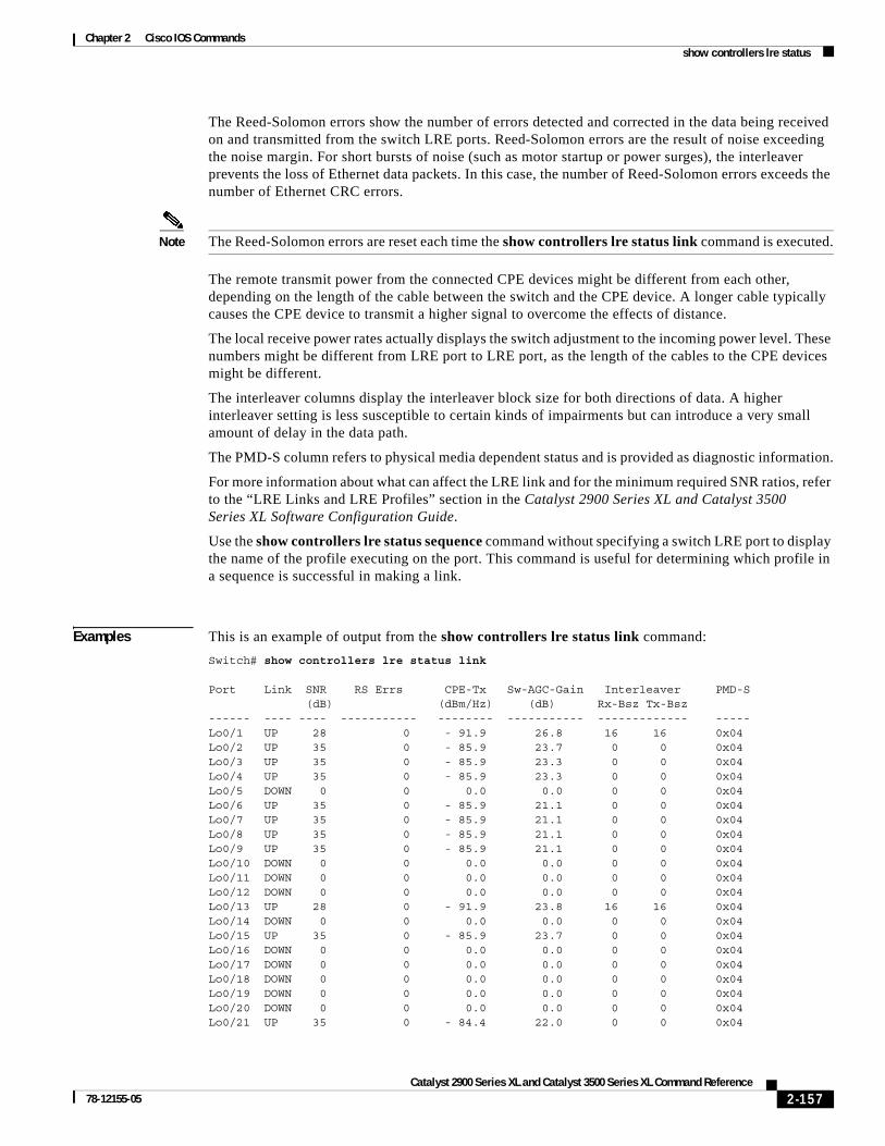
Chapter 2 Cisco IOS Commandsshow controllers lre status
The Reed-Solomon errors show the number of errors detected and corrected in the data being received on and transmitted from the switch LRE ports. Reed-Solomon errors are the result of noise exceeding the noise margin. For short bursts of noise (such as motor startup or power surges), the interleaver prevents the loss of Ethernet data packets. In this case, the number of Reed-Solomon errors exceeds the number of Ethernet CRC errors.
Note The Reed-Solomon errors are reset each time the show controllers lre status link command is executed.
The remote transmit power from the connected CPE devices might be different from each other, depending on the length of the cable between the switch and the CPE device. A longer cable typically causes the CPE device to transmit a higher signal to overcome the effects of distance.
The local receive power rates actually displays the switch adjustment to the incoming power level. These numbers might be different from LRE port to LRE port, as the length of the cables to the CPE devices might be different.
The interleaver columns display the interleaver block size for both directions of data. A higher interleaver setting is less susceptible to certain kinds of impairments but can introduce a very small amount of delay in the data path.
The PMD-S column refers to physical media dependent status and is provided as diagnostic information.
For more information about what can affect the LRE link and for the minimum required SNR ratios, refer to the “LRE Links and LRE Profiles” section in the Catalyst 2900 Series XL and Catalyst 3500 Series XL Software Configuration Guide.
Use the show controllers lre status sequence command without specifying a switch LRE port to display the name of the profile executing on the port. This command is useful for determining which profile in a sequence is successful in making a link.
Examples This is an example of output from the show controllers lre status link command:
Switch# show controllers lre status link
Port Link SNR RS Errs CPE-Tx Sw-AGC-Gain Interleaver PMD-S (dB) (dBm/Hz) (dB) Rx-Bsz Tx-Bsz ------ ---- ---- ----------- -------- ----------- ------------- -----Lo0/1 UP 28 0 - 91.9 26.8 16 16 0x04Lo0/2 UP 35 0 - 85.9 23.7 0 0 0x04Lo0/3 UP 35 0 - 85.9 23.3 0 0 0x04Lo0/4 UP 35 0 - 85.9 23.3 0 0 0x04Lo0/5 DOWN 0 0 0.0 0.0 0 0 0x04Lo0/6 UP 35 0 - 85.9 21.1 0 0 0x04Lo0/7 UP 35 0 - 85.9 21.1 0 0 0x04Lo0/8 UP 35 0 - 85.9 21.1 0 0 0x04Lo0/9 UP 35 0 - 85.9 21.1 0 0 0x04Lo0/10 DOWN 0 0 0.0 0.0 0 0 0x04Lo0/11 DOWN 0 0 0.0 0.0 0 0 0x04Lo0/12 DOWN 0 0 0.0 0.0 0 0 0x04Lo0/13 UP 28 0 - 91.9 23.8 16 16 0x04Lo0/14 DOWN 0 0 0.0 0.0 0 0 0x04Lo0/15 UP 35 0 - 85.9 23.7 0 0 0x04Lo0/16 DOWN 0 0 0.0 0.0 0 0 0x04Lo0/17 DOWN 0 0 0.0 0.0 0 0 0x04Lo0/18 DOWN 0 0 0.0 0.0 0 0 0x04Lo0/19 DOWN 0 0 0.0 0.0 0 0 0x04Lo0/20 DOWN 0 0 0.0 0.0 0 0 0x04Lo0/21 UP 35 0 - 84.4 22.0 0 0 0x04
2-157Catalyst 2900 Series XL and Catalyst 3500 Series XL Command Reference
78-12155-05

Chapter 2 Cisco IOS Commandsshow controllers lre status
Lo0/22 DOWN 0 0 0.0 0.0 24 0 0x04Lo0/23 DOWN 0 0 0.0 0.0 0 0 0x04Lo0/24 DOWN 0 0 0.0 0.0 0 0 0x04
This is an example of output from the show controllers lre status profile:
Switch# show controllers lre status profile
Port Link Uptime Profile DSRate USRate Fail------ ---- -------- ------------------- ------ ------ ----Lo0/1 UP 2d23h LRE-10 12.500 12.500 0Lo0/2 UP 2d23h LRE-10 4.167 1.563 0Lo0/3 UP 2d23h LRE-10 4.167 1.563 0Lo0/4 UP 2d23h LRE-10 4.167 1.563 0Lo0/5 DOWN 00:00:00 LRE-10 0.000 0.000 0Lo0/6 UP 2d23h LRE-10 4.167 1.563 0Lo0/7 UP 2d23h LRE-10 4.167 1.563 0Lo0/8 UP 2d23h LRE-10 4.167 1.563 0Lo0/9 UP 2d23h LRE-10 4.167 1.563 0Lo0/10 DOWN 00:00:00 LRE-10 0.000 0.000 0Lo0/11 DOWN 00:00:00 LRE-10 0.000 0.000 0Lo0/12 DOWN 00:00:00 LRE-10 0.000 0.000 0Lo0/13 UP 2d23h LRE-10 12.500 12.500 0Lo0/14 DOWN 00:00:00 LRE-10 0.000 0.000 0Lo0/15 UP 2d23h LRE-10 4.167 1.563 0Lo0/16 DOWN 00:00:00 LRE-10 0.000 0.000 0Lo0/17 DOWN 00:00:00 LRE-10 0.000 0.000 0Lo0/18 DOWN 00:00:00 LRE-10 0.000 0.000 0Lo0/19 DOWN 00:00:00 LRE-10 0.000 0.000 0Lo0/20 DOWN 00:00:00 LRE-10 0.000 0.000 0Lo0/21 UP 2d23h LRE-10 4.167 1.563 0Lo0/22 DOWN 00:00:00 LRE-10 0.000 0.000 0Lo0/23 DOWN 00:00:00 LRE-10 0.000 0.000 0Lo0/24 DOWN 00:00:00 LRE-10 0.000 0.000 0
This is an example of output from the show controllers lre status sequence detail:
Switch# show controller lre status sequence detail
Related Commands Command Description
show controllers lre interface-id actual
Displays the actual values of the LRE link on a specific switch LRE port.
show controllers lre interface-id admin
Displays the administrative settings of the LRE link on a specific switch LRE port.
show controllers lre profile Displays information about the LRE profiles available on the switch.
debug lre Enables debugging of LRE-related events.
2-158Catalyst 2900 Series XL and Catalyst 3500 Series XL Command Reference
78-12155-05

Chapter 2 Cisco IOS Commandsshow controllers lre version
show controllers lre versionUse the show controllers lre version privileged EXEC command to display the version numbers of the various components (hardware, firmware, patch software, and bootloader firmware and application firmware) that make up the switch Long-Reach Ethernet (LRE) interface and the LRE customer premises equipment (CPE) interface.
show controllers lre version [interface-id] [ | {begin | exclude | include} expression]
Syntax Description
Command Modes Privileged EXEC
Command History
Usage Guidelines Using the show controllers lre version command without specifying a switch LRE port displays the version numbers of all switch LRE interfaces and the CPE interfaces of all connected CPE devices.
Examples This is an example of output from the show controllers lre version command:
Switch# show controllers lre version
--- SWITCH --- ------------ CPE -----------Interface Hw Sw Patch Hw Sw Patch Boot AppLo0/1 32 B4 50 32 B4 50 NA NALo0/2 32 B4 50 32 B4 50 NA NALo0/3 32 B4 50 32 B4 50 NA NALo0/4 32 B4 50 32 B4 50 NA NALo0/5 32 B4 50 00 00 00 NA NALo0/6 32 B4 50 32 B4 51 NA NALo0/7 32 B4 50 32 B4 51 NA NALo0/8 32 B4 50 32 B4 51 NA NALo0/9 32 B4 50 32 B4 50 NA NALo0/10 32 B4 50 00 00 00 NA NALo0/11 32 B4 50 00 00 00 NA NALo0/12 32 B4 50 00 00 00 NA NALo0/13 32 B4 50 32 B4 51 NA NALo0/14 32 B4 50 00 00 00 NA NALo0/15 32 B4 50 32 B4 50 NA NALo0/16 32 B4 50 00 00 00 NA NALo0/17 32 B4 50 00 00 00 NA NA
interface-id (Optional) ID of the switch LRE port.
| begin (Optional) Display begins with the line that matches the expression.
| exclude (Optional) Display excludes lines that match the expression.
| include (Optional) Display includes lines that match the specified expression.
expression Expression in the output to use as a reference point.
Release Modification
12.0(5)WC1 This command was first introduced.
12.0(5)WC4 The bootloader firmware version was added.
2-159Catalyst 2900 Series XL and Catalyst 3500 Series XL Command Reference
78-12155-05

Chapter 2 Cisco IOS Commandsshow controllers lre version
Lo0/18 32 B4 50 00 00 00 NA NALo0/19 32 B4 50 00 00 00 NA NALo0/20 32 B4 50 00 00 00 NA NALo0/21 32 B4 50 32 B4 49 NA NALo0/22 32 B4 50 00 00 00 NA NALo0/23 32 B4 50 00 00 00 NA NALo0/24 32 B4 50 00 00 00 NA NA
Related Commands Command Description
debug lre Enables debugging of LRE-related events.
show controllers lre cpe info Displays the model numbers of the LRE CPE devices connected to the LRE switch and shows whether or not the connected CPE devices meet the minimum requirements to be managed by the LRE switch.
show controllers lre version mfg Displays the revision and serial numbers of the connected Cisco LRE CPE board, assembly, and system.
2-160Catalyst 2900 Series XL and Catalyst 3500 Series XL Command Reference
78-12155-05

Chapter 2 Cisco IOS Commandsshow controllers lre version mfg
show controllers lre version mfgUse the show controllers lre version mfg privileged EXEC command to display the revision and serial numbers of the connected Cisco Long-Reach Ethernet (LRE) customer premises equipment (CPE) device board, assembly, and system.
show controllers lre version mfg [interface-id] [ | {begin | exclude | include} expression]
Syntax Description
Command Modes Privileged EXEC
Command History
Examples This is an example of output from the show controllers lre version mfg command:
switch# show controllers lre version mfgLo0/1 Assembly Revision Number:Model Number :CISCO575-LREModel Revision Number :A0Board Assembly Number :Board Serial Number :System Serial Number :
Lo0/2 Assembly Revision Number:Model Number :Model Revision Number :Board Assembly Number :Board Serial Number :System Serial Number :
Lo0/3 Assembly Revision Number:Model Number :Model Revision Number :Board Assembly Number :Board Serial Number :Lo0/4 Assembly Revision Number:Model Number :Model Revision Number :Board Assembly Number :
interface-id (Optional) ID of the switch LRE port.
| begin (Optional) Display begins with the line that matches the expression.
| exclude (Optional) Display excludes lines that match the expression.
| include (Optional) Display includes lines that match the specified expression.
expression Expression in the output to use as a reference point.
Release Modification
12.0(5)WC1 This command was first introduced.
12.0(5)WC4 This command was extended to support the Cisco 585 LRE CPE device.
2-161Catalyst 2900 Series XL and Catalyst 3500 Series XL Command Reference
78-12155-05

Chapter 2 Cisco IOS Commandsshow controllers lre version mfg
Board Serial Number :System Serial Number : Lo0/5 Assembly Revision Number:Model Number :Model Revision Number :Board Assembly Number :Board Serial Number :System Serial Number : Lo0/6 Assembly Revision Number:02 Model Number :CISCO575-LREModel Revision Number :A0Board Assembly Number :73-5579-07 Board Serial Number :FAA0506010H System Serial Number :
Related Commands Command Description
debug lre Enables debugging of LRE-related events.
show controllers lre version Displays the version number of the hardware, software, and patch software components of the switch LRE interface and the CPE LRE interface.
show controllers lre cpe info Displays the model numbers of the LRE CPE devices connected to the LRE switch and shows whether or not the connected CPE devices meet the minimum requirements to be managed by the LRE switch.
2-162Catalyst 2900 Series XL and Catalyst 3500 Series XL Command Reference
78-12155-05

Chapter 2 Cisco IOS Commandsshow current
show currentUse the show current VLAN database command to display the current VLAN database on the switch or a selected VLAN from it.
show current [vlan-id]
Syntax Description
Command Modes VLAN database
Command History
Examples This is an example of output from the show current command. It displays the current VLAN database.
Switch(vlan)# show current
VLAN ISL Id: 1 Name: default Media Type: Ethernet VLAN 802.10 Id: 100001 State: Operational MTU: 1500 Translational Bridged VLAN: 1002 Translational Bridged VLAN: 1003
VLAN ISL Id: 2 Name: VLAN0002 Media Type: Ethernet VLAN 802.10 Id: 100002 State: Operational MTU: 1500
VLAN ISL Id: 3 Name: VLAN0003 Media Type: Ethernet VLAN 802.10 Id: 100003 State: Operational MTU: 4000
VLAN ISL Id: 4 Name: VLAN0004 Media Type: Ethernet VLAN 802.10 Id: 100004 State: Operational MTU: 1500
vlan-id (Optional) ID of the VLAN in the current database. If this variable is omitted, the entire VLAN database displays, included the pruning state and version 2 mode. Valid IDs are from 1 to 1005; do not enter leading zeros.
Release Modification
11.2(8)SA4 This command was first introduced.
2-163Catalyst 2900 Series XL and Catalyst 3500 Series XL Command Reference
78-12155-05

Chapter 2 Cisco IOS Commandsshow current
VLAN ISL Id: 5 Name: VLAN0005 Media Type: Ethernet VLAN 802.10 Id: 100005 State: Operational MTU: 1500
VLAN ISL Id: 6 Name: VLAN0006 Media Type: Ethernet VLAN 802.10 Id: 100006 State: Operational MTU: 1500
This is an example of output from the show current 2 command. It displays only VLAN 2 of the current database.
Switch(vlan)# show current 2
VLAN ISL Id: 2 Name: VLAN0002 Media Type: Ethernet VLAN 802.10 Id: 100002 State: Operational MTU: 1500
Related Commands Command Description
show changes Displays the differences between the VLAN database currently on the switch and the proposed VLAN database.
show proposed Displays the proposed VLAN database or a selected VLAN from it.
2-164Catalyst 2900 Series XL and Catalyst 3500 Series XL Command Reference
78-12155-05
Chapter 2 Cisco IOS Commandsshow diags
show diagsUse the show diags user EXEC command to display the state of a port or all ports on the switch.
show diags [addr-move | link-flap] [interface-id] [ | {begin | exclude | include} expression]
Syntax Description
Command Modes User EXEC
Command History
Usage Guidelines Use the show diags command without specifying a port to show the state of all ports on the switch.
Use the show diags link-flap command to check if link flapping on a port is occurring. Link flapping can be caused by a loose connection to a port or by numerous changes to a port connection.
Use the show diags addr-move command to check if address flapping is occurring. Address flapping can be caused when the switch learns the same MAC address on different ports on the same VLAN. The address table keeps changing because the MAC address is first learned on one interface, is learned on another interface, and then relearned on the previous interface, and so on. This can be caused by a loop that Spanning Tree Protocol (STP) has not blocked.
Examples This is an example of output from the show link-flap command.
Switch> show diags link-flap fa0/1Interface Total Last Min-------------------- ---------- ----------FastEthernet0/1 14 0FastEthernet0/2 12 0FastEthernet0/3 1 0FastEthernet0/7 6 0FastEthernet0/12 6 0
addr-move Show learned address movement count and rate.
link-flap Show link up/down count and rate.
interface-id (Optional) ID of the Fast Ethernet or Long-Reach Ethernet (LRE) port number.
| begin (Optional) Display begins with the line that matches the expression.
| exclude (Optional) Display excludes lines that match the expression.
| include (Optional) Display includes lines that match the specified expression.
expression Expression in the output to use as a reference point.
Release Modification
12.0(5)XU This command was first introduced.
2-165Catalyst 2900 Series XL and Catalyst 3500 Series XL Command Reference
78-12155-05

Chapter 2 Cisco IOS Commandsshow env
show envUse the show env privileged EXEC command to display fan and temperature information for the 3524-PWR-XL switch.
show env {all | fan | temperature}
Syntax Description
Command Modes Privileged EXEC
Command History
Examples This is an example of output from the show env all command:
Switch# show env allFAN 1 is OK
FAN 2 is OK
FAN 3 is OK
FAN 4 is OK
FAN 5 is OK
TEMPERATURE is OK
This is an example of output from the show env fans command:
FAN 1 is OK
FAN 2 is OK
FAN 3 is OK
FAN 4 is FAULTY
FAN 5 is OK
all Display both fan and temperature environmental status.
fan Display the switch fan status.
temperature Display the switch temperature status.
Release Modification
12.0(5)XU This command was first introduced.
2-166Catalyst 2900 Series XL and Catalyst 3500 Series XL Command Reference
78-12155-05

Chapter 2 Cisco IOS Commandsshow errdisable detect
show errdisable detectUse the show errdisable detect user EXEC command to display error-disable detection status.
show errdisable detect [ | {begin | exclude | include} expression]
Syntax Description
Command Modes User EXEC
Command History
Usage Guidelines Expressions are case sensitive. For example, if you enter exclude output, the lines that contain output are not displayed, but the lines that contain Output are displayed.
Examples This is an example of output from the show errdisable detect command:
Switch> show errdisable detect
ErrDisable Reason Detection status----------------- ----------------udld Enabled
Related Commands
begin (Optional) Display begins with the line that matches the expression.
exclude (Optional) Display excludes lines that match the expression.
include (Optional) Display includes lines that match the specified expression.
expression Expression in the output to use as a reference point.
Release Modification
12.0(5)WC5 This command was first introduced.
Command Description
errdisable detect cause Enables error-disable detection for a specific cause or all causes.
show errdisable recovery Displays error-disable recovery timer information.
2-167Catalyst 2900 Series XL and Catalyst 3500 Series XL Command Reference
78-12155-05

Chapter 2 Cisco IOS Commandsshow errdisable recovery
show errdisable recoveryUse the show errdisable recovery user EXEC command to display the error-disable recovery timer information.
show errdisable recovery [ | {begin | exclude | include} expression]
Syntax Description
Command Modes User EXEC
Command History
Usage Guidelines Expressions are case sensitive. For example, if you enter exclude output, the lines that contain output are not displayed, but the lines that contain Output are displayed.
Examples This is an example of output from the show errdisable recovery command:
Switch> show errdisable recovery
ErrDisable Reason Timer Status----------------- --------------udld Disabled
Timer interval: 300 seconds
Interfaces that will be enabled at the next timeout:
Interface Errdisable reason Time left(sec)--------- ----------------- --------------
Related Commands
begin (Optional) Display begins with the line that matches the expression.
exclude (Optional) Display excludes lines that match the expression.
include (Optional) Display includes lines that match the specified expression.
expression Expression in the output to use as a reference point.
Release Modification
12.0(5)WC5 This command was first introduced.
Command Description
errdisable recovery Configures the recover mechanism variables.
show errdisable detect Displays error disable detection status.
2-168Catalyst 2900 Series XL and Catalyst 3500 Series XL Command Reference
78-12155-05

Chapter 2 Cisco IOS Commandsshow file systems
show file systemsUse the show file systems privileged EXEC command to display file system information.
show file systems [ | {begin | exclude | include} expression]
Syntax Description
Command Types Privileged EXEC
Command History
Examples This is an example of output from the show file systems command:
Switch# show file systemsFile Systems:
Size(b) Free(b) Type Flags Prefixes* 3612672 1234432 flash rw flash: 3612672 1234432 unknown rw zflash: - - opaque ro bs: 32768 30917 nvram rw nvram: - - network rw tftp: - - opaque rw null: - - opaque rw system: - - network rw rcp:
begin (Optional) Display begins with the line that matches the expression.
exclude (Optional) Display excludes lines that match the expression.
include (Optional) Display includes lines that match the specified expression.
expression Expression in the output to use as a reference point.
Release Modification
11.2(8)SA5 This command was first introduced.
2-169Catalyst 2900 Series XL and Catalyst 3500 Series XL Command Reference
78-12155-05

Chapter 2 Cisco IOS Commandsshow interface
show interfaceUse the show interface privileged EXEC command to display the administrative and operational status of a switching port.
show interface [interface-id | vlan number] [accounting | crb | description | ethernet | fair-queue | irb | link-trap | mac-accounting | precedence | random-detect | rate-limit | status | switchport [allowed-vlan | prune-elig | native-vlan] | trbrf | type ] [ | {begin | exclude | include} expression]
Syntax Description interface-id (Optional) ID of the module and port.
vlan number VLAN number of the management VLAN. Valid IDs are from 1 to 1000. Do not enter leading zeros.
accounting (Optional) Display interface accounting information.
crb (Optional) Display interface concurrent routing and bridging information.
description (Optional) Display interface description.
ethernet (Optional) Display Ethernet VLAN information.
fair-queue (Optional) Display weighted fair queueing (WFQ) information for the interface.
irb (Optional) Display interface integrated routing and bridging information.
link-trap (Optional) Display interface traps when there is not a link.
mac-accounting (Optional) Display the interface MAC accounting information.
precedence (Optional) Display the interface precedence accounting information.
random-detect (Optional) Display weighted random early detection (WRED) information.
rate-limit (Optional) Display the interface rate-limit information.
status (Optional) Display the status of the interface.
switchport (Optional) Display the administrative and operational status of a switching (nonrouting) port. This option is only available if an interface is specified.
• allowed-vlan—Display the VLAN IDs that receive and transmit all types of traffic on the trunk port. By default, all VLAN IDs are included.
• prune-elig—Display the VLAN ID whose flood traffic can be pruned. By default, all VLANs, except VLAN 1 and 1002 through 1005, are pruning-eligible on the trunk.
• native-vlan—Display the native VLAN ID for untagged traffic when the port is in 802.1Q trunking mode.
trbrf (Optional) Show bridge relay function(BRF) token ring VLAN type.
type (Optional) Show VLAN types.
begin (Optional) Display begins with the line that matches the expression.
exclude (Optional) Display excludes lines that match the expression.
include (Optional) Display includes lines that match the specified expression.
expression Expression in the output to use as a reference point.
2-170Catalyst 2900 Series XL and Catalyst 3500 Series XL Command Reference
78-12155-05

Chapter 2 Cisco IOS Commandsshow interface
Command Modes Privileged EXEC
Command History
Usage Guidelines Use the show interface command without specifying a port to display the administrative and operational status of all ports on the switch.
Examples This is an example of output from the show interface gi0/1 flow-control command.
Switch# show interface gi0/1 flow-controlAny,Input only
The display shows two values separated by a comma. The first value is the value that you configured by using the flowcontrol command or the Cluster Management Suite (CMS) (or the default value if you did not configure it). The first value can be one of these settings:
• None—Flow control is not enabled.
• Asymmetric—Only the transmit or receive flow control is enabled.
• Symmetric—Both the transmit and receive flow control are enabled.
• Any—Any type of flow control is supported.
The second value represents the flow control value that is autonegotiated with the link partner and can be one of these settings:
• None—Flow control with the link partner does not occur.
• Output only—The interface can only transmit pause frames but not receive any.
• Input only—The interface can only receive pause frames but not transmit any.
• Output and Input—The interface can transmit and receive pause frames.
Note If you enter the show interface interface-id flow-control command on a GigaStack Gigabit Interface Converter (GBIC), the first value in the display is the setting for both GigaStack GBIC ports, and the second value is the autonegotiated setting for both ports.
This is an example of output from the show interface fa0/2 switchport command. Table 2-2 describes each field in the display.
Switch# show interface fa0/2 switchportName: fa0/2Switchport: EnabledAdministrative Mode: TrunkOperational Mode: TrunkAdministrative Trunking Encapsulation: ISLOperational Trunking Encapsulation: ISL
Release Modification
11.2(8)SA4 This command was first introduced.
11.2(8)SA5 The native-vlan keyword was added.
12.0(5)XP The vlan number keyword was added.
12.0(5)XU The pruning keyword was added.
12.0(5)XW The status keyword was added.
2-171Catalyst 2900 Series XL and Catalyst 3500 Series XL Command Reference
78-12155-05

Chapter 2 Cisco IOS Commandsshow interface
Negotiation of Trunking: DisabledAccess Mode VLAN: 0 (inactive)Trunking Native Mode VLAN: 1 (default)Trunking VLANs Enabled: 1-30, 50, 100-1005Trunking VLANs Active: 1-4Pruning VLANs Enabled: 2-1001
Priority for untagged frames: 0Voice VLAN: noneAppliance trust: none
This is an example of output from the show interface fa0/9 pruning command when pruning is enabled in the VTP domain:
Switch# show interface fa0/9 pruningPort Vlans pruned for lack of request by neighborFa0/9 3,4
Port Vlans traffic requested of neighborFa0/9 1-3
This is an example of output from the show interface status command:
Switch# show interface statusPort Name Status Vlan Duplex Speed Type------- ------------------ ------------ -------- ------ ------- ----Fa0/1 connected trunk A-Full A-100 100BASE-TX/FXFa0/2 notconnect 1 Auto Auto 100BASE-TX/FX
Table 2-2 Show Interface fa0/2 Switchport Field Descriptions
Field Description
Name Displays the port name.
Switchport Displays the administrative and operational status of the port. In this display, the port is in switch port mode.
Administrative Mode
Operational Mode
Displays the administrative and operational mode.
Administrative Trunking Encapsulation
Operation Trunking Encapsulation
Negotiation of Trunking
Displays the administrative and operational encapsulation method. Also displays whether trunking negotiation is enabled.
Access Mode VLAN Displays the VLAN ID to which the port is configured.
Trunking Native Mode VLAN
Trunking VLANs Enabled
Trunking VLANs Active
Lists the VLAN ID of the trunk that is in native mode. Lists the allowed VLANs on the trunk. Lists the active VLANs on the trunk.
Pruning VLANs Enabled Lists the VLANs that are pruning-eligible.
Priority for untagged frames Displays the port priority on incoming untagged frames.
Voice VLAN Displays the voice VLAN.
Appliance trust Displays how the appliance (telephone) connected to the specified port handles priority traffic that is received on its incoming port.
2-172Catalyst 2900 Series XL and Catalyst 3500 Series XL Command Reference
78-12155-05

Chapter 2 Cisco IOS Commandsshow interface
Fa0/3 notconnect 1 Auto Auto 100BASE-TX/FXFa0/4 notconnect 1 Auto Auto 100BASE-TX/FXFa0/5 notconnect 1 Auto Auto 100BASE-TX/FXFa0/6 notconnect 1 Auto Auto 100BASE-TX/FXFa0/7 notconnect 1 Auto Auto 100BASE-TX/FXFa0/8 notconnect 1 Auto Auto 100BASE-TX/FXFa0/9 notconnect 1 Auto Auto 100BASE-TX/FX <output truncated>
Related Commands Command Description
switchport access Configures a port as a static-access or dynamic-access port.
switchport mode Configures the VLAN membership mode of a port.
switchport multi Configures a list of VLANs to which the port is associated.
switchport priority default Provides a default port priority for the incoming untagged frames.
switchport trunk pruning Configures the VLAN pruning-eligible list for ports in trunking mode.
switchport voice vlan Configures the voice VLAN on the port.
2-173Catalyst 2900 Series XL and Catalyst 3500 Series XL Command Reference
78-12155-05

Chapter 2 Cisco IOS Commandsshow ip igmp profile
show ip igmp profile Use the show ip igmp profile privileged EXEC command to display the details of an Internet Group Management Protocol (IGMP) profile entry.
show ip igmp profile [profile number] [ | {begin | exclude | include} expression]
Syntax Description
Command Modes Privileged EXEC
Command History
Usage Guidelines Use the show ip igmp profile command with an IGMP filter profile to display parameters for a specific IGMP profile.
Expressions are case sensitive. For example, if you enter | exclude output, the lines that contain output are not displayed, but the lines that contain Output are displayed.
Examples This is an example of output from the show ip igmp profile command:
host1# show ip igmp profile 30IGMP Profile 30range 233.1.1.1 233.255.255.255range 235.1.1.1 235.255.255.255host1#
Related Commands
profile number
The IGMP profile to be displayed. The range is from 1 to 4294967295.
| begin (Optional) Display begins with the line that matches the specified expression.
| exclude (Optional) Display excludes lines that match the specified expression.
| include (Optional) Display includes lines that match the specified expression.
expression Expression in the output to use as a reference point.
Release Modification
12.0(5)WC3 This command was first introduced.
Command Description
ip igmp filter Apply a specific IGMP profile to an interface.
ip igmp profile Define an IGMP profile.
show running-config interface Displays the running configuration on the switch, including any profiles assigned to a port.
2-174Catalyst 2900 Series XL and Catalyst 3500 Series XL Command Reference
78-12155-05

Chapter 2 Cisco IOS Commandsshow local ethernet-statistics
show local ethernet-statisticsUse the show local ethernet-statistics privileged EXEC command to display the details of the local Long-Reach Ethernet (LRE) chipset.
show local ethernet-statistics [interface-id] [ | {begin | exclude | include} expression]
Syntax Description
Command Modes Privileged EXEC
Command History
Usage Guidelines Using the show local ethernet-statistics command without specifying a switch LRE port displays the Ethernet statistics of all switch LRE interfaces.
Examples This is an example of output from the show local ethernet-statistics command:
Switch# show local ethernet-statistics lo0/1
Transmit Receive 0 Bytes 0 Bytes 0 Frames 0 Frames 0 Broadcast frames 0 Pause frames 0 Pause frames 130 1 collision frames 1028 Alignment errors 0 Multiple collisions 0 Collisions and Runts 0 Late collisions 0 Oversize frames 0 Excessive collisions 0 FCS errors 0 Deferred frames 0 Carrier sense errors
Related Commands
interface-id ID of the switch LRE port.
begin (Optional) Display begins with the line that matches the expression.
exclude (Optional) Display excludes lines that match the expression.
include (Optional) Display includes lines that match the specified expression.
expression Expression in the output to use as a reference point.
Release Modification
12.0(6)WC6 This command was first introduced.
Command Description
show remote ethernet-statistics
Displays the Ethernet statistics for a remote CPE device.
2-175Catalyst 2900 Series XL and Catalyst 3500 Series XL Command Reference
78-12155-05

Chapter 2 Cisco IOS Commandsshow lre upgrade binaries
show lre upgrade binariesUse the show lre upgrade binaries privileged EXEC command to display the Long-Reach Ethernet (LRE) binaries present on the system Flash memory.
show lre upgrade binaries [ | {begin | exclude | include} expression]
Syntax Description
Command Modes Privileged EXEC
Command History
Usage Guidelines Using the show lre upgrade binaries command displays the LRE binary information for each interface.
The output of the command shows the path to the LRE binaries, which are always in the same directory as the IOS image. LRE binary file names consist of:
• The device family. A device family could be an LRE switch or a customer premises equipment (CPE) device.
• The function of the firmware, such as an upgrade for an application, for the bootloader, or for the LRE chipset.
• The firmware version.
Files marked with an exclamation point (!) are version description files. A version description file is for informational purposes only and are not candidates for upgrade. Version description files are used to determine whether or not a CPE device on an LRE link is running a supported LRE binary version.
Examples This example of output is from the show lre upgrade binaries command:
Switch# show lre upgrade binaries
Directory containing LRE binaries is flash:/lre-bin/
LRE Binary:CISCO585-LRE_MC8051boot_01.03.00,Flash file name:CISCO585-LRE_MC8051boot_01.03.00.bin!
LRE Binary:CISCO585-LRE_vdslsngl_51.00.00,Flash file name:CISCO585-LRE_vdslsngl_51.00.00.bin
| begin (Optional) Display begins with the line that matches the specified expression.
| exclude (Optional) Display excludes lines that match the specified expression.
| include (Optional) Display includes lines that match the specified expression.
expression Expression in the output to use as a reference point.
Release Modification
12.0(5)WC6 This command was first introduced.
2-176Catalyst 2900 Series XL and Catalyst 3500 Series XL Command Reference
78-12155-05

Chapter 2 Cisco IOS Commandsshow lre upgrade binaries
LRE Binary:CISCO575-LRE_vdslsngl_50.00.00,Flash file name:CISCO575-LRE_vdslsngl_50.00.00.bin
LRE Binary:CISCO585-LRE_MC8051appl_01.03.00,Flash file name:CISCO585-LRE_MC8051appl_01.03.00.bin!
LRE Binary:CISCO2900-LRE_vdslsngl_50.00.00,Flash file name:CISCO2900-LRE_vdslsngl_50.00.00.bin
Switch#
Related Commands Command Description
show lre upgrade status Displays the upgrade status on all ports in the switch.
show lre upgrade version Displays the versions of binaries on local and remote ends on all ports.
2-177Catalyst 2900 Series XL and Catalyst 3500 Series XL Command Reference
78-12155-05

Chapter 2 Cisco IOS Commandsshow lre upgrade status
show lre upgrade statusUse the show lre upgrade status privileged EXEC command to display the upgrade status on all ports in the switch.
show lre upgrade status [ | {begin | exclude | include} expression]
Syntax Description
Command Modes Privileged EXEC
Command History
Usage Guidelines Use the show lre upgrade status command during LRE upgrades to display both the local and remote upgrade status levels in progress on an LRE link:
None—An upgrade is not in progress.
Pending—An upgrade is initalized, but transfer has not begun.
Active—The data transfer is in progress.
Cmplt—An upgrade is complete.
When an upgrade is running on an LRE switch controller, the status for the controller does not change to complete until all hardware elements on the controller are completed.
Other information displayed includes the local current (lcl curr) and proposed configuration (cfg) for each LRE interface. LRE binary file names consist of:
• The device family. A device family could be an LRE switch or a customer premises equipment (CPE) device.
• The function of the firmware, such as an upgrade for an application, for the bootloader, or for the LRE or CPE chipsets.
• The firmware version.
During data transfer but before the upgrade completes, the status also shows the amount of time in hours and minutes that the upgrade has been in progress. It also shows the number of attempts.
| begin (Optional) Display begins with the line that matches the specified expression.
| exclude (Optional) Display excludes lines that match the specified expression.
| include (Optional) Display includes lines that match the specified expression.
expression Expression in the output to use as a reference point.
Release Modification
12.0(5)WC6 This command was first introduced.
2-178Catalyst 2900 Series XL and Catalyst 3500 Series XL Command Reference
78-12155-05

Chapter 2 Cisco IOS Commandsshow lre upgrade status
Examples This example shows the status of an upgrade at completion:
Switch# show lre upgrade statusLo0/1: lcl curr:CISCO2900-LRE_vdslsngl_50.00.00 new:CISCO2900-LRE_vdslsngl_50.00.00 Status:Cmplt, Bytes Sent:0 rmt curr:CISCO575-LRE_vdslsngl_50.00.00 new:CISCO575-LRE_vdslsngl_50.00.00 Status:Cmplt, Bytes Sent:2830 Lo0/2: lcl curr:CISCO2900-LRE_vdslsngl_50.00.00 new:CISCO2900-LRE_vdslsngl_50.00.00 Status:Cmplt, Bytes Sent:0 rmt curr:CISCO575-LRE_vdslsngl_50.00.00 new:CISCO575-LRE_vdslsngl_50.00.00 Status:Cmplt, Bytes Sent:2830 Lo0/3: lcl curr:CISCO2900-LRE_vdslsngl_50.00.00 new:CISCO2900-LRE_vdslsngl_50.00.00 Status:Cmplt, Bytes Sent:0 rmt curr:CISCO575-LRE_vdslsngl_50.00.00 new:CISCO575-LRE_vdslsngl_50.00.00 Status:Cmplt, Bytes Sent:2830 Lo0/4: lcl curr:CISCO2900-LRE_vdslsngl_50.00.00 new:CISCO2900-LRE_vdslsngl_50.00.00 Status:Cmplt, Bytes Sent:0 rmt curr:CISCO575-LRE_vdslsngl_50.00.00 new:CISCO575-LRE_vdslsngl_50.00.00 Status:Cmplt, Bytes Sent:2830 Lo0/5: lcl curr:CISCO2900-LRE_vdslsngl_50.00.00 new:CISCO2900-LRE_vdslsngl_50.00.00 Status:Cmplt, Bytes Sent:0 rmt curr:CISCO575-LRE_vdslsngl_50.00.00 new:CISCO575-LRE_vdslsngl_50.00.00 Status:Cmplt, Bytes Sent:2830 Lo0/6: lcl curr:CISCO2900-LRE_vdslsngl_50.00.00 new:CISCO2900-LRE_vdslsngl_50.00.00 Status:Cmplt, Bytes Sent:0 rmt curr:CISCO575-LRE_vdslsngl_50.00.00 new:CISCO575-LRE_vdslsngl_50.00.00 Status:Cmplt, Bytes Sent:2830 Lo0/7: lcl curr:CISCO2900-LRE_vdslsngl_50.00.00 new:CISCO2900-LRE_vdslsngl_50.00.00 Status:Cmplt, Bytes Sent:0 rmt curr:CISCO575-LRE_vdslsngl_50.00.00 new:CISCO575-LRE_vdslsngl_50.00.00 Status:Cmplt, Bytes Sent:2830 Lo0/8: lcl curr:CISCO2900-LRE_vdslsngl_50.00.00 new:CISCO2900-LRE_vdslsngl_50.00.00 Status:Cmplt, Bytes Sent:0 rmt curr:CISCO575-LRE_vdslsngl_50.00.00 new:CISCO575-LRE_vdslsngl_50.00.00 Status:Cmplt, Bytes Sent:2830 Lo0/9: lcl curr:CISCO2900-LRE_vdslsngl_50.00.00 new:CISCO2900-LRE_vdslsngl_50.00.00 Status:Cmplt, Bytes Sent:0 No remote devices on Lo0/9Lo0/10: lcl curr:CISCO2900-LRE_vdslsngl_50.00.00 new:CISCO2900-LRE_vdslsngl_50.00.00 Status:Cmplt, Bytes Sent:0 No remote devices on Lo0/10Lo0/11: lcl curr:CISCO2900-LRE_vdslsngl_50.00.00 new:CISCO2900-LRE_vdslsngl_50.00.00 Status:Cmplt, Bytes Sent:0 No remote devices on Lo0/11Lo0/12: lcl curr:CISCO2900-LRE_vdslsngl_50.00.00 new:CISCO2900-LRE_vdslsngl_50.00.00 Status:Cmplt, Bytes Sent:0 No remote devices on Lo0/12
Switch#
2-179Catalyst 2900 Series XL and Catalyst 3500 Series XL Command Reference
78-12155-05

Chapter 2 Cisco IOS Commandsshow lre upgrade status
Related Commands Command Description
show lre upgrade binaries Displays the LRE binary information present on the system Flash memory.
show lre upgrade version Displays the versions of binaries on local and remote ends on all ports.
2-180Catalyst 2900 Series XL and Catalyst 3500 Series XL Command Reference
78-12155-05
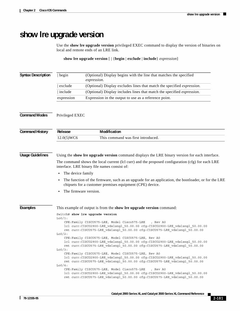
Chapter 2 Cisco IOS Commandsshow lre upgrade version
show lre upgrade versionUse the show lre upgrade version privileged EXEC command to display the version of binaries on local and remote ends of an LRE link.
show lre upgrade version [ | {begin | exclude | include} expression]
Syntax Description
Command Modes Privileged EXEC
Command History
Usage Guidelines Using the show lre upgrade version command displays the LRE binary version for each interface.
The command shows the local current (lcl curr) and the proposed configuration (cfg) for each LRE interface. LRE binary file names consist of:
• The device family
• The function of the firmware, such as an upgrade for an application, the bootloader, or for the LRE chipsets for a customer premises equipment (CPE) device.
• The firmware version.
Examples This example of output is from the show lre upgrade version command:
Switch# show lre upgrade versionLo0/1: CPE:Family CISCO575-LRE, Model Cisco575-LRE , Rev A0 lcl curr:CISCO2900-LRE_vdslsngl_50.00.00 cfg:CISCO2900-LRE_vdslsngl_50.00.00 rmt curr:CISCO575-LRE_vdslsngl_50.00.00 cfg:CISCO575-LRE_vdslsngl_50.00.00Lo0/2: CPE:Family CISCO575-LRE, Model CISCO575-LRE, Rev A0 lcl curr:CISCO2900-LRE_vdslsngl_50.00.00 cfg:CISCO2900-LRE_vdslsngl_50.00.00 rmt curr:CISCO575-LRE_vdslsngl_50.00.00 cfg:CISCO575-LRE_vdslsngl_50.00.00Lo0/3: CPE:Family CISCO575-LRE, Model CISCO575-LRE, Rev A0 lcl curr:CISCO2900-LRE_vdslsngl_50.00.00 cfg:CISCO2900-LRE_vdslsngl_50.00.00 rmt curr:CISCO575-LRE_vdslsngl_50.00.00 cfg:CISCO575-LRE_vdslsngl_50.00.00Lo0/4: CPE:Family CISCO575-LRE, Model Cisco575-LRE , Rev A0 lcl curr:CISCO2900-LRE_vdslsngl_50.00.00 cfg:CISCO2900-LRE_vdslsngl_50.00.00 rmt curr:CISCO575-LRE_vdslsngl_50.00.00 cfg:CISCO575-LRE_vdslsngl_50.00.00
| begin (Optional) Display begins with the line that matches the specified expression.
| exclude (Optional) Display excludes lines that match the specified expression.
| include (Optional) Display includes lines that match the specified expression.
expression Expression in the output to use as a reference point.
Release Modification
12.0(5)WC6 This command was first introduced.
2-181Catalyst 2900 Series XL and Catalyst 3500 Series XL Command Reference
78-12155-05

Chapter 2 Cisco IOS Commandsshow lre upgrade version
Lo0/5: CPE:Family CISCO575-LRE, Model Cisco575-LRE , Rev A0 lcl curr:CISCO2900-LRE_vdslsngl_50.00.00 cfg:CISCO2900-LRE_vdslsngl_50.00.00 rmt curr:CISCO575-LRE_vdslsngl_50.00.00 cfg:CISCO575-LRE_vdslsngl_50.00.00Lo0/6: CPE:Family CISCO575-LRE, Model Cisco575-LRE , Rev A0 lcl curr:CISCO2900-LRE_vdslsngl_50.00.00 cfg:CISCO2900-LRE_vdslsngl_50.00.00 rmt curr:CISCO575-LRE_vdslsngl_50.00.00 cfg:CISCO575-LRE_vdslsngl_50.00.00Lo0/7: CPE:Family CISCO575-LRE, Model Cisco575-LRE , Rev A0 lcl curr:CISCO2900-LRE_vdslsngl_50.00.00 cfg:CISCO2900-LRE_vdslsngl_50.00.00 rmt curr:CISCO575-LRE_vdslsngl_50.00.00 cfg:CISCO575-LRE_vdslsngl_50.00.00Lo0/8: CPE:Family CISCO575-LRE, Model Cisco575-LRE , Rev A0 lcl curr:CISCO2900-LRE_vdslsngl_50.00.00 cfg:CISCO2900-LRE_vdslsngl_50.00.00 rmt curr:CISCO575-LRE_vdslsngl_50.00.00 cfg:CISCO575-LRE_vdslsngl_50.00.00Lo0/9: CPE:Family NONE, Model NONE, Rev NONE lcl curr:CISCO2900-LRE_vdslsngl_50.00.00 cfg:CISCO2900-LRE_vdslsngl_50.00.00Lo0/10: CPE:Family NONE, Model NONE, Rev NONE lcl curr:CISCO2900-LRE_vdslsngl_50.00.00 cfg:CISCO2900-LRE_vdslsngl_50.00.00Lo0/11: CPE:Family NONE, Model NONE, Rev NONE lcl curr:CISCO2900-LRE_vdslsngl_50.00.00 cfg:CISCO2900-LRE_vdslsngl_50.00.00Lo0/12: CPE:Family NONE, Model NONE, Rev NONE lcl curr:CISCO2900-LRE_vdslsngl_50.00.00 cfg:CISCO2900-LRE_vdslsngl_50.00.00
Related Commands Command Description
show lre upgrade binaries Displays the LRE binary information present on the system Flash memory.
show lre upgrade status Displays the upgrade status on all ports in the switch.
2-182Catalyst 2900 Series XL and Catalyst 3500 Series XL Command Reference
78-12155-05
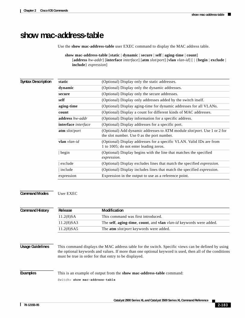
Chapter 2 Cisco IOS Commandsshow mac-address-table
show mac-address-tableUse the show mac-address-table user EXEC command to display the MAC address table.
show mac-address-table [static | dynamic | secure | self | aging-time | count][address hw-addr] [interface interface] [atm slot/port] [vlan vlan-id] [ | {begin | exclude | include} expression]
Syntax Description
Command Modes User EXEC
Command History
Usage Guidelines This command displays the MAC address table for the switch. Specific views can be defined by using the optional keywords and values. If more than one optional keyword is used, then all of the conditions must be true in order for that entry to be displayed.
Examples This is an example of output from the show mac-address-table command:
Switch> show mac-address-table
static (Optional) Display only the static addresses.
dynamic (Optional) Display only the dynamic addresses.
secure (Optional) Display only the secure addresses.
self (Optional) Display only addresses added by the switch itself.
aging-time (Optional) Display aging-time for dynamic addresses for all VLANs.
count (Optional) Display a count for different kinds of MAC addresses.
address hw-addr (Optional) Display information for a specific address.
interface interface (Optional) Display addresses for a specific port.
atm slot/port (Optional) Add dynamic addresses to ATM module slot/port. Use 1 or 2 for the slot number. Use 0 as the port number.
vlan vlan-id (Optional) Display addresses for a specific VLAN. Valid IDs are from 1 to 1005; do not enter leading zeros.
| begin (Optional) Display begins with the line that matches the specified expression.
| exclude (Optional) Display excludes lines that match the specified expression.
| include (Optional) Display includes lines that match the specified expression.
expression Expression in the output to use as a reference point.
Release Modification
11.2(8)SA This command was first introduced.
11.2(8)SA3 The self, aging-time, count, and vlan vlan-id keywords were added.
11.2(8)SA5 The atm slot/port keywords were added.
2-183Catalyst 2900 Series XL and Catalyst 3500 Series XL Command Reference
78-12155-05

Chapter 2 Cisco IOS Commandsshow mac-address-table
Dynamic Addresses Count: 9Secure Addresses (User-defined) Count: 0Static Addresses (User-defined) Count: 0System Self Addresses Count: 41Total MAC addresses: 50Non-static Address Table:Destination Address Address Type VLAN Destination Port------------------- ------------ ---- --------------------0010.0de0.e289 Dynamic 1 FastEthernet0/10010.7b00.1540 Dynamic 2 FastEthernet0/50010.7b00.1545 Dynamic 2 FastEthernet0/50060.5cf4.0076 Dynamic 1 FastEthernet0/10060.5cf4.0077 Dynamic 1 FastEthernet0/10060.5cf4.1315 Dynamic 1 FastEthernet0/10060.70cb.f301 Dynamic 1 FastEthernet0/100e0.1e42.9978 Dynamic 1 FastEthernet0/100e0.1e9f.3900 Dynamic 1 FastEthernet0/1
Related Commands Command Description
clear mac-address-table Deletes entries from the MAC address table.
2-184Catalyst 2900 Series XL and Catalyst 3500 Series XL Command Reference
78-12155-05
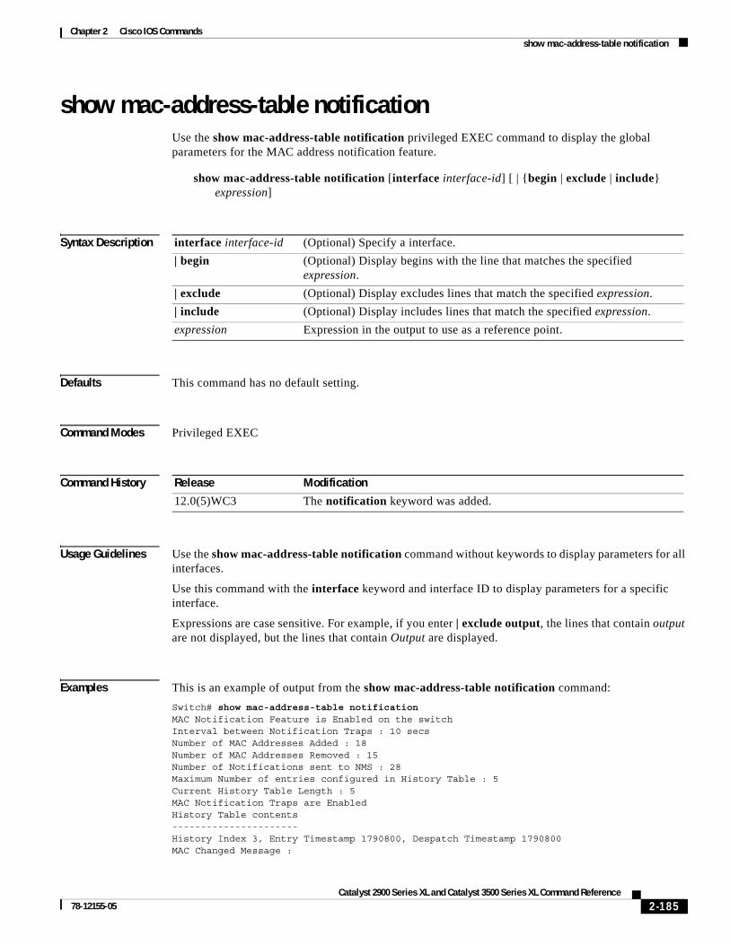
Chapter 2 Cisco IOS Commandsshow mac-address-table notification
show mac-address-table notificationUse the show mac-address-table notification privileged EXEC command to display the global parameters for the MAC address notification feature.
show mac-address-table notification [interface interface-id] [ | {begin | exclude | include} expression]
Syntax Description
Defaults This command has no default setting.
Command Modes Privileged EXEC
Command History
Usage Guidelines Use the show mac-address-table notification command without keywords to display parameters for all interfaces.
Use this command with the interface keyword and interface ID to display parameters for a specific interface.
Expressions are case sensitive. For example, if you enter | exclude output, the lines that contain output are not displayed, but the lines that contain Output are displayed.
Examples This is an example of output from the show mac-address-table notification command:
Switch# show mac-address-table notificationMAC Notification Feature is Enabled on the switchInterval between Notification Traps : 10 secsNumber of MAC Addresses Added : 18Number of MAC Addresses Removed : 15Number of Notifications sent to NMS : 28Maximum Number of entries configured in History Table : 5Current History Table Length : 5MAC Notification Traps are EnabledHistory Table contents----------------------History Index 3, Entry Timestamp 1790800, Despatch Timestamp 1790800MAC Changed Message :
interface interface-id (Optional) Specify a interface.
| begin (Optional) Display begins with the line that matches the specified expression.
| exclude (Optional) Display excludes lines that match the specified expression.
| include (Optional) Display includes lines that match the specified expression.
expression Expression in the output to use as a reference point.
Release Modification
12.0(5)WC3 The notification keyword was added.
2-185Catalyst 2900 Series XL and Catalyst 3500 Series XL Command Reference
78-12155-05

Chapter 2 Cisco IOS Commandsshow mac-address-table notification
Operation: Deleted Vlan: 1 MAC Addr: 00c0.4301.101b Dot1dBasePort:16
History Index 4, Entry Timestamp 1794810, Despatch Timestamp 1794810MAC Changed Message :Operation: Added Vlan: 1 MAC Addr: 00c0.4301.101b Module: 0 Port: 2
History Index 0, Entry Timestamp 1825868, Despatch Timestamp 1825868MAC Changed Message :Operation: Deleted Vlan: 1 MAC Addr: 00c0.4301.101b Module: 0 Port: 2
History Index 1, Entry Timestamp 1850929, Despatch Timestamp 1850929MAC Changed Message :Operation: Added Vlan: 1 MAC Addr: 00c0.4301.101b Module: 0 Port: 2
History Index 2, Entry Timestamp 1880988, Despatch Timestamp 1880988MAC Changed Message :Operation: Deleted Vlan: 1 MAC Addr: 00c0.4301.101b Module: 0 Port: 2
Switch#
This is an example of output from the show mac-address-table notification interface command for all interfaces on a switch:
MAC Notification Flags For All Ethernet Interfaces :----------------------------------------------------Interface MAC Added Trap MAC Removed Trap--------- -------------- ----------------FastEthernet0/1 Disabled DisabledFastEthernet0/2 Disabled DisabledFastEthernet0/3 Disabled DisabledFastEthernet0/4 Enabled EnabledFastEthernet0/5 Disabled DisabledFastEthernet0/6 Disabled DisabledFastEthernet0/7 Disabled DisabledFastEthernet0/8 Disabled DisabledFastEthernet0/9 Disabled DisabledFastEthernet0/10 Disabled DisabledFastEthernet0/11 Disabled DisabledFastEthernet0/12 Disabled DisabledFastEthernet0/13 Disabled DisabledFastEthernet0/14 Disabled DisabledFastEthernet0/15 Disabled DisabledFastEthernet0/16 Disabled DisabledFastEthernet0/17 Disabled DisabledFastEthernet0/18 Disabled DisabledFastEthernet0/19 Disabled DisabledFastEthernet0/20 Disabled DisabledFastEthernet0/21 Disabled DisabledFastEthernet0/22 Disabled DisabledFastEthernet0/23 Disabled DisabledFastEthernet0/24 Disabled Disabled
This is an example of output from the show mac-address-table notification interface interface-id command for one interface on a switch:
Interface MAC Added Trap MAC Removed Trap--------- -------------- ----------------FastEthernet0/4 Enabled Enabled
Switch#
2-186Catalyst 2900 Series XL and Catalyst 3500 Series XL Command Reference
78-12155-05

Chapter 2 Cisco IOS Commandsshow mac-address-table notification
Related Commands Command Description
clear mac-address-table notification
Clears the counters maintained by the MAC address notification feature.
mac-address-table notification Enables the MAC notification feature.
snmp trap mac-notification Enables MAC-notification traps on a port.
2-187Catalyst 2900 Series XL and Catalyst 3500 Series XL Command Reference
78-12155-05

Chapter 2 Cisco IOS Commandsshow mvr
show mvrUse the show mvr privileged EXEC command without keywords to display the multicast VLAN registration (MVR) global parameter values, including whether or not MVR is enabled, the maximum query response time, and the multicast VLAN number.
show mvr [ | {begin | exclude | include} expression]
Syntax Description
Command Modes Privileged EXEC
Command History
Examples This example shows how to view the MVR global parameter values:
Switch# show mvrMVR EnabledMVR multicast vlan: 2MVR Current multicast groups: 1MVR Global query response time: 100 (tenths of sec)
Related Commands
| begin (Optional) Display begins with the line that matches the specified expression.
| exclude (Optional) Display excludes lines that match the specified expression.
| include (Optional) Display includes lines that match the specified expression.
expression Expression in the output to use as a reference point.
Release Modification
12.0(5)XW This command was first introduced.
Command Description
show mvr interface Displays the configured MVR interfaces or displays the multicast groups to which a receiver port belongs.
show mvr members Displays all receiver ports that are members of an MVR multicast group.
mvr (global configuration) (global configuration mode)
Enables and configures multicast VLAN registration on the switch.
mvr (interface configuration) (interface configuration mode)
Configures MVR ports.
2-188Catalyst 2900 Series XL and Catalyst 3500 Series XL Command Reference
78-12155-05

Chapter 2 Cisco IOS Commandsshow mvr interface
show mvr interfaceUse the show mvr interface privileged EXEC command without keywords to display the multicast VLAN registration (MVR) receiver and source ports. Use the command with keywords to display MVR parameters for a specific receiver port.
show mvr interface [interface-id [members [vlan vlan-id]]] [ | {begin | exclude | include} expression]
Syntax Description
Usage Guidelines If the entered port identification is a non-MVR port or a source port, the command returns an error message. For receiver ports, it displays the port type and per port parameters, such as maximum threshold and Immediate Leave setting.
Command Modes Privileged EXEC
Command History
Examples This example shows how to display all MVR interfaces:
Switch# show mvr interfaceMVR PORTSPort: Fa0/1 Type: RECEIVER Status: ACTIVEPort: Fa0/2 Type: RECEIVER Status: ACTIVE Port: Fa0/3 Type: SOURCE Status: ACTIVE
This example shows how to view the MVR parameters for Fast Ethernet port 0/1:
Switch# show mvr interface fastethernet 0/1Interface: Fa0/1 Threshold: 20 Immediate Leave: Disabled Multicast packets received: 13
interface-id (Optional) Enter a receiver port identification to display parameters for the specified port.
members (Optional) Display all MVR groups that the specified receive port is a member of.
vlan vlan-id (Optional) Display the VLAN to which the receiver port belongs.
| begin (Optional) Display begins with the line that matches the specified expression.
| exclude (Optional) Display excludes lines that match the specified expression.
| include (Optional) Display includes lines that match the specified expression.
expression Expression in the output to use as a reference point.
Release Modification
12.0(5)XW This command was first introduced.
2-189Catalyst 2900 Series XL and Catalyst 3500 Series XL Command Reference
78-12155-05
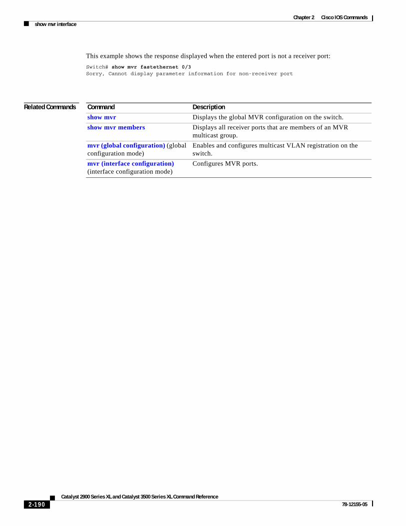
Chapter 2 Cisco IOS Commandsshow mvr interface
This example shows the response displayed when the entered port is not a receiver port:
Switch# show mvr fastethernet 0/3Sorry, Cannot display parameter information for non-receiver port
Related Commands Command Description
show mvr Displays the global MVR configuration on the switch.
show mvr members Displays all receiver ports that are members of an MVR multicast group.
mvr (global configuration) (global configuration mode)
Enables and configures multicast VLAN registration on the switch.
mvr (interface configuration) (interface configuration mode)
Configures MVR ports.
2-190Catalyst 2900 Series XL and Catalyst 3500 Series XL Command Reference
78-12155-05

Chapter 2 Cisco IOS Commandsshow mvr members
show mvr membersUse the show mvr members privileged EXEC command to display all receiver ports that are members of an IP multicast group.
show mvr members [ip-address] | [{begin | exclude | include} expression]
Syntax Description
Usage Guidelines The show mvr members command only applies to receiver ports. All source ports are members of all multicast groups.
Command Modes Privileged EXEC
Command History
Examples This example shows how to view the members of any IP multicast group:
Switch# show mvr membersMVR Group IP:239.255.0.1 Vlan 2 Interface:Fa0/16 DYNAMIC ACTIVE Vlan 2 Interface:Fa0/17 DYNAMIC ACTIVE
MVR Group IP:239.255.0.2 Vlan 2 Interface:Fa0/15 DYNAMIC ACTIVE Vlan 2 Interface:Fa0/17 DYNAMIC ACTIVE Vlan 2 Interface:Fa0/20 DYNAMIC ACTIVE
MVR Group IP:239.255.0.3 Vlan 2 Interface:Fa0/23 DYNAMIC ACTIVE Vlan 2 Interface:Fa0/16 DYNAMIC ACTIVE
MVR Group IP:239.255.0.4 Vlan 2 Interface:Fa0/26 DYNAMIC ACTIVE Vlan 2 Interface:Fa0/16 DYNAMIC ACTIVE Vlan 2 Interface:Fa0/23 DYNAMIC ACTIVE
MVR Group IP:239.255.0.5 Vlan 2 Interface:Fa0/15 DYNAMIC ACTIVE Vlan 2 Interface:Fa0/14 DYNAMIC ACTIVE
ip-address (Optional) The IP multicast address. If the address is entered, all receiver ports that are members of the multicast group are displayed. If no address is entered, all members of all MVR groups are listed.
| begin (Optional) Display begins with the line that matches the specified expression.
| exclude (Optional) Display excludes lines that match the specified expression.
| include (Optional) Display includes lines that match the specified expression.
expression Expression in the output to use as a reference point.
Release Modification
12.0(5)XW This command was first introduced.
2-191Catalyst 2900 Series XL and Catalyst 3500 Series XL Command Reference
78-12155-05

Chapter 2 Cisco IOS Commandsshow mvr members
MVR Group IP:239.255.0.6 Vlan 2 Interface:Fa0/17 DYNAMIC ACTIVE Vlan 2 Interface:Fa0/18 DYNAMIC ACTIVE Vlan 2 Interface:Fa0/20 DYNAMIC ACTIVE Vlan 2 Interface:Fa0/23 DYNAMIC ACTIVE Vlan 2 Interface:Fa0/15 DYNAMIC ACTIVE
This example shows how to view the members of the IP multicast group 239.255.0.4:
Switch# show mvr members 239.255.0.4MVR Group IP:239.255.0.4 Vlan 2 Interface:Fa0/26 DYNAMIC ACTIVE Vlan 2 Interface:Fa0/16 DYNAMIC ACTIVE Vlan 2 Interface:Fa0/23 DYNAMIC ACTIVE
Related Commands Command Description
show mvr Displays the global MVR configuration on the switch.
show mvr interface Displays the configured MVR interfaces or displays the multicast groups to which a receiver port belongs.
mvr (global configuration) Enables and configures multicast VLAN registration on the switch.
mvr (interface configuration) Configures MVR ports.
2-192Catalyst 2900 Series XL and Catalyst 3500 Series XL Command Reference
78-12155-05
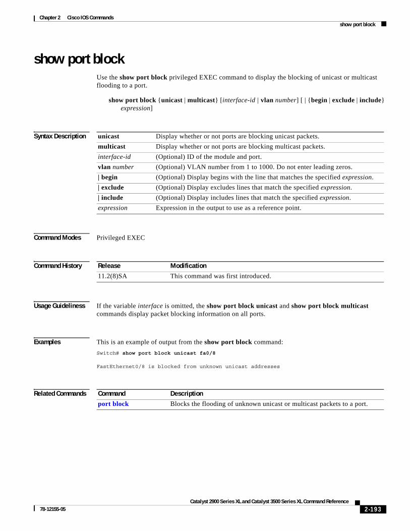
Chapter 2 Cisco IOS Commandsshow port block
show port blockUse the show port block privileged EXEC command to display the blocking of unicast or multicast flooding to a port.
show port block {unicast | multicast} [interface-id | vlan number] [ | {begin | exclude | include} expression]
Syntax Description
Command Modes Privileged EXEC
Command History
Usage Guideliness If the variable interface is omitted, the show port block unicast and show port block multicast commands display packet blocking information on all ports.
Examples This is an example of output from the show port block command:
Switch# show port block unicast fa0/8
FastEthernet0/8 is blocked from unknown unicast addresses
Related Commands
unicast Display whether or not ports are blocking unicast packets.
multicast Display whether or not ports are blocking multicast packets.
interface-id (Optional) ID of the module and port.
vlan number (Optional) VLAN number from 1 to 1000. Do not enter leading zeros.
| begin (Optional) Display begins with the line that matches the specified expression.
| exclude (Optional) Display excludes lines that match the specified expression.
| include (Optional) Display includes lines that match the specified expression.
expression Expression in the output to use as a reference point.
Release Modification
11.2(8)SA This command was first introduced.
Command Description
port block Blocks the flooding of unknown unicast or multicast packets to a port.
2-193Catalyst 2900 Series XL and Catalyst 3500 Series XL Command Reference
78-12155-05

Chapter 2 Cisco IOS Commandsshow port group
show port groupUse the show port group privileged EXEC command to display the ports that belong to a port group.
show port group [group-number] | [{begin | exclude | include} expression] [ | {begin | exclude | include} expression]
Syntax Description
Command Modes Privileged EXEC
Command History
Usage Guidelines If the variable group-number is omitted, the show port group command displays all port groups on the switch. Port groups are not supported on Long-Reach Ethernet (LRE) ports.
Examples This is an example of output from the show port group command:
Switch# show port group 1
Group Interface----- --------------- 1 FastEthernet0/1 1 FastEthernet0/4
Related Commands
group-number (Optional) Port group to which the port is assigned.
| begin (Optional) Display begins with the line that matches the specified expression.
| exclude (Optional) Display excludes lines that match the specified expression.
| include (Optional) Display includes lines that match the specified expression.
expression Expression in the output to use as a reference point.
Release Modification
11.2(8)SA3 This command was first introduced.
Command Description
port group Assigns a port to a Fast EtherChannel or Gigabit EtherChannel port group.
2-194Catalyst 2900 Series XL and Catalyst 3500 Series XL Command Reference
78-12155-05
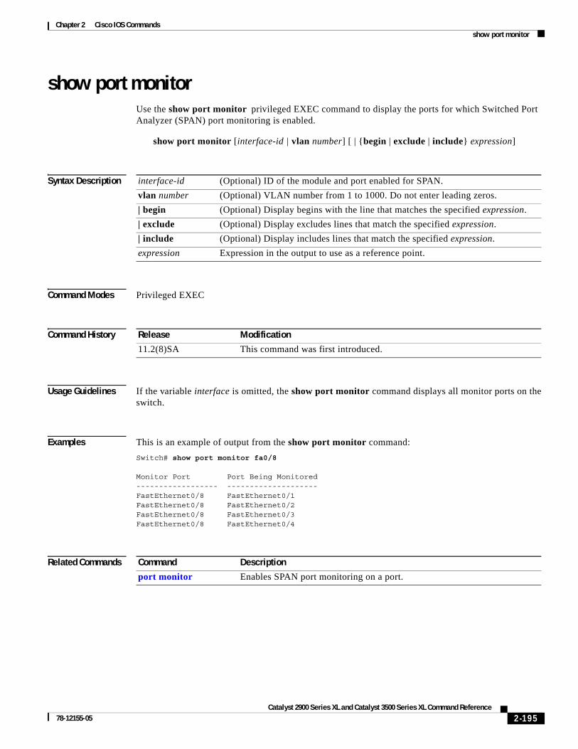
Chapter 2 Cisco IOS Commandsshow port monitor
show port monitorUse the show port monitor privileged EXEC command to display the ports for which Switched Port Analyzer (SPAN) port monitoring is enabled.
show port monitor [interface-id | vlan number] [ | {begin | exclude | include} expression]
Syntax Description
Command Modes Privileged EXEC
Command History
Usage Guidelines If the variable interface is omitted, the show port monitor command displays all monitor ports on the switch.
Examples This is an example of output from the show port monitor command:
Switch# show port monitor fa0/8
Monitor Port Port Being Monitored------------------ --------------------FastEthernet0/8 FastEthernet0/1FastEthernet0/8 FastEthernet0/2FastEthernet0/8 FastEthernet0/3FastEthernet0/8 FastEthernet0/4
Related Commands
interface-id (Optional) ID of the module and port enabled for SPAN.
vlan number (Optional) VLAN number from 1 to 1000. Do not enter leading zeros.
| begin (Optional) Display begins with the line that matches the specified expression.
| exclude (Optional) Display excludes lines that match the specified expression.
| include (Optional) Display includes lines that match the specified expression.
expression Expression in the output to use as a reference point.
Release Modification
11.2(8)SA This command was first introduced.
Command Description
port monitor Enables SPAN port monitoring on a port.
2-195Catalyst 2900 Series XL and Catalyst 3500 Series XL Command Reference
78-12155-05

Chapter 2 Cisco IOS Commandsshow port network
show port networkUse the show port network privileged EXEC command to display the network port defined for the switch or VLAN.
show port network [interface-id | vlan number] [ | {begin | exclude | include} expression]
Syntax Description
Command Modes Privileged EXEC
Command History
Usage Guidelines If the variable interface is omitted, the show port network command displays all network ports on the switch.
Examples This is an example of output from the show port network command:
Switch# show port network
Network Port VLAN ID------------ -------FastEthernet0/11 1
Related Commands
interface-id (Optional) ID of the module and port.
vlan number (Optional) VLAN number from 1 to 1000. Do not enter leading zeros.
| begin (Optional) Display begins with the line that matches the specified expression.
| exclude (Optional) Display excludes lines that match the specified expression.
| include (Optional) Display includes lines that match the specified expression.
expression Expression in the output to use as a reference point.
Release Modification
11.2(8)SA4 This command was first introduced.
Command Description
port network Defines a port as the switch network port. All traffic with unknown unicast addresses is forwarded to the network port on the same VLAN.
2-196Catalyst 2900 Series XL and Catalyst 3500 Series XL Command Reference
78-12155-05

Chapter 2 Cisco IOS Commandsshow port protected
show port protectedUse the show port protected privileged EXEC command to display the port protected mode for all ports.
show port protected [ | {begin | exclude | include} expression]
Syntax Description
Command Modes Privileged EXEC
Command History
Examples This is an example of output from the show port protected command:
Switch# show port protected
FastEthernet0/3 is in protected modeGigabitEthernet1/1 is in protected mode
Related Commands
| begin (Optional) Display begins with the line that matches the specified expression.
| exclude (Optional) Display excludes lines that match the specified expression.
| include (Optional) Display includes lines that match the specified expression.
expression Expression in the output to use as a reference point.
Release Modification
12.0(5)XU This command was first introduced.
Command Description
port protected Isolates unicast, multicast, and broadcast traffic at Layer 2 from other protected ports on the same switch.
2-197Catalyst 2900 Series XL and Catalyst 3500 Series XL Command Reference
78-12155-05

Chapter 2 Cisco IOS Commandsshow port security
show port security Use the show port security privileged EXEC command to display the port security settings defined for the port.
show port security [interface-id | vlan number] [ | {begin | exclude | include} expression]
Syntax Description
Command Modes Privileged EXEC
Command History
Usage Guidelines If the variable interface is omitted, the show port security command displays all secure ports on the switch.
Examples This is an example of output from the show port security command for fixed port 07:
Switch# show port security fa0/7
Secure Port Secure Addr Secure Addr Security Security Action Cnt (Current) Cnt (Max) Reject Cnt--------------- ------------- ----------- ---------- ----------------FastEthernet0/7 0 132 0 Send Trap
Related Commands
interface-id (Optional) ID of the module and port.
vlan number (Optional) VLAN number from 1 to 1000. Do not enter leading zeros.
| begin (Optional) Display begins with the line that matches the specified expression.
| exclude (Optional) Display excludes lines that match the specified expression.
| include (Optional) Display includes lines that match the specified expression.
expression Expression in the output to use as a reference point.
Release Modification
11.2(8)SA This command was first introduced.
Command Description
port security Enables port security on a port.
2-198Catalyst 2900 Series XL and Catalyst 3500 Series XL Command Reference
78-12155-05

Chapter 2 Cisco IOS Commandsshow port storm-control
show port storm-control Use the show port storm-control privileged EXEC command to display the packet-storm control information. This command also displays the action that the switch takes when the thresholds are reached.
show port storm-control [interface] [{broadcast | multicast | unicast | history}] [ | {begin | exclude | include} expression]
Syntax Description
Command Modes Privileged EXEC
Command History
Usage Guidelines If the variable interface is omitted, the show port storm-control command displays storm control settings on all ports on the switch.
You can display broadcast, multicast, or unicast packet-storm information by using the corresponding keyword.
Examples This is an example of output from the show port storm-control command:
Switch# show port storm-control
Interface Filter State Trap State Rising Falling Current Traps Sent--------- ------------- ------------- ------ ------- ------- ----------Fa0/1 <inactive> <inactive> 1000 200 0 0Fa0/2 <inactive> <inactive> 500 250 0 0Fa0/3 <inactive> <inactive> 500 250 0 0Fa0/4 <inactive> <inactive> 500 250 0 0
interface (Optional) Port for which information is to be displayed.
broadcast (Optional) Display broadcast storm information.
multicast (Optional) Display multicast storm information.
unicast (Optional) Display unicast storm information.
history (Optional) Display storm history on a per-port basis.
| begin (Optional) Display begins with the line that matches the specified expression.
| exclude (Optional) Display excludes lines that match the specified expression.
| include (Optional) Display includes lines that match the specified expression.
expression Expression in the output to use as a reference point.
Release Modification
11.2(8)SA This command was first introduced.
12.0(5)XU The broadcast, multicast, unicast, and history keywords were added.
2-199Catalyst 2900 Series XL and Catalyst 3500 Series XL Command Reference
78-12155-05

Chapter 2 Cisco IOS Commandsshow port storm-control
Related Commands Command Description
port storm-control Enables broadcast, multicast, or unicast storm control on a port.
2-200Catalyst 2900 Series XL and Catalyst 3500 Series XL Command Reference
78-12155-05

Chapter 2 Cisco IOS Commandsshow power inline
show power inlineUse the show power inline privileged EXEC command to display the power status for the specified port or for all ports on the Catalyst 3524-PWR XL switch.
show power inline [interface-id] [actual | configured] [ | {begin | exclude | include} expression]
Syntax Description
Command Modes Privileged EXEC
Command History
Examples This is an example of output from the show power inline fa0/4 actual command:
Switch# show power inline fa0/4 actualInterface Power-------------------- -----FastEthernet0/4 no
Related Commands
interface-id (Optional) ID of the module and port.
actual (Optional) Display the current power status, which might not be the same as the configured power.
configured (Optional) Display the configured power status.
| begin (Optional) Display begins with the line that matches the specified expression.
| exclude (Optional) Display excludes lines that match the specified expression.
| include (Optional) Display includes lines that match the specified expression.
expression Expression in the output to use as a reference point.
Release Modification
12.0(5)XU This command was first introduced.
Command Description
power inline Determines how inline power is applied to devices on the specified Fast Ethernet port of the Catalyst 3524-PWR XL switch.
2-201Catalyst 2900 Series XL and Catalyst 3500 Series XL Command Reference
78-12155-05
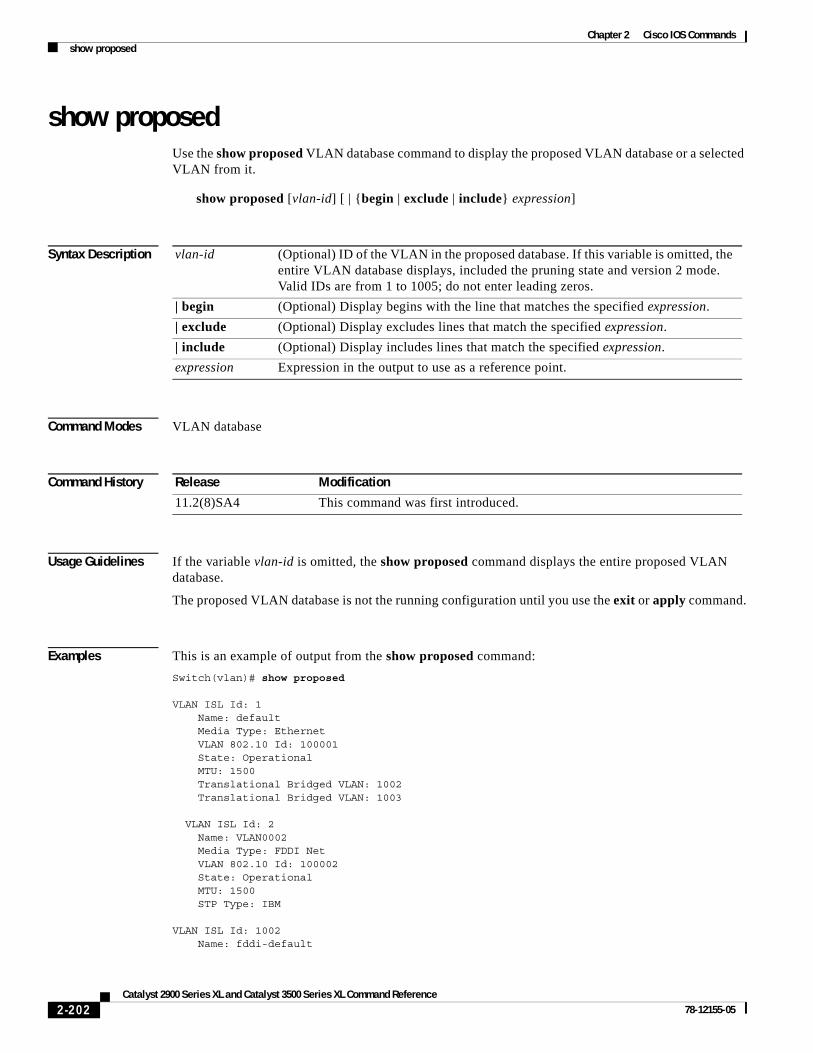
Chapter 2 Cisco IOS Commandsshow proposed
show proposedUse the show proposed VLAN database command to display the proposed VLAN database or a selected VLAN from it.
show proposed [vlan-id] [ | {begin | exclude | include} expression]
Syntax Description
Command Modes VLAN database
Command History
Usage Guidelines If the variable vlan-id is omitted, the show proposed command displays the entire proposed VLAN database.
The proposed VLAN database is not the running configuration until you use the exit or apply command.
Examples This is an example of output from the show proposed command:
Switch(vlan)# show proposed
VLAN ISL Id: 1 Name: default Media Type: Ethernet VLAN 802.10 Id: 100001 State: Operational MTU: 1500 Translational Bridged VLAN: 1002 Translational Bridged VLAN: 1003
VLAN ISL Id: 2 Name: VLAN0002 Media Type: FDDI Net VLAN 802.10 Id: 100002 State: Operational MTU: 1500 STP Type: IBM
VLAN ISL Id: 1002 Name: fddi-default
vlan-id (Optional) ID of the VLAN in the proposed database. If this variable is omitted, the entire VLAN database displays, included the pruning state and version 2 mode. Valid IDs are from 1 to 1005; do not enter leading zeros.
| begin (Optional) Display begins with the line that matches the specified expression.
| exclude (Optional) Display excludes lines that match the specified expression.
| include (Optional) Display includes lines that match the specified expression.
expression Expression in the output to use as a reference point.
Release Modification
11.2(8)SA4 This command was first introduced.
2-202Catalyst 2900 Series XL and Catalyst 3500 Series XL Command Reference
78-12155-05

Chapter 2 Cisco IOS Commandsshow proposed
Media Type: FDDI VLAN 802.10 Id: 101002 State: Operational MTU: 1500 Bridge Type: SRB Translational Bridged VLAN: 1 Translational Bridged VLAN: 1003VLAN ISL Id: 1003 Name: trcrf-default Media Type: TRCRF VLAN 802.10 Id: 101003 State: Operational MTU: 4472 Bridge Type: SRB Ring Number: 3276 Bridge Number: 1 Parent VLAN: 1005 Maximum ARE Hop Count: 7 Maximum STE Hop Count: 7 Backup CRF Mode: Disabled Translational Bridged VLAN: 1 Translational Bridged VLAN: 1002
VLAN ISL Id: 1004 Name: fddinet-default Media Type: FDDI Net VLAN 802.10 Id: 101004 State: Operational MTU: 1500 Bridge Type: SRB Bridge Number: 1 STP Type: IBM
VLAN ISL Id: 1005 Name: trbrf-default Media Type: TRBRF VLAN 802.10 Id: 101005 State: Operational MTU: 4472 Bridge Type: SRB Bridge Number: 15 STP Type: IBM
Related Commands Command Description
show changes Displays the differences between the VLAN database currently on the switch and the proposed VLAN database.
show current Displays the VLAN database on the switch or a selected VLAN from it.
2-203Catalyst 2900 Series XL and Catalyst 3500 Series XL Command Reference
78-12155-05

Chapter 2 Cisco IOS Commandsshow remote ethernet-statistics
show remote ethernet-statisticsUse the show remote ethernet-statistics user EXEC command to display the statistics for the Ethernet ports on the Long-Reach Ethernet (LRE) customer premises equipment (CPE) devices connected to the switch LRE ports.
show remote ethernet-statistics [interface-id] [ | {begin | exclude | include} expression]
Syntax Description
Command Modes User EXEC
Command History
Usage Guidelines Using the show remote ethernet-statistics user EXEC command without specifying a switch LRE port displays the Ethernet statistics for all switch LRE ports connected to LRE CPE devices.
When a Cisco 585 LRE CPE device is connected to a switch LRE port, this command displays the statistics for the five Ethernet connections on the CPE device. Statistics for CPE Fast Ethernet Ports 1 through 4 are the statistics for the CPE Ethernet links between the CPE device and remote Ethernet devices such as PCs and television-set-top boxes. Statistics for CPE Fast Ethernet Port 5 are the statistics for the LRE link between the CPE device and the switch LRE port.
Examples This is an example of output from the show remote ethernet-statistics user EXEC command when a Cisco 575 LRE CPE device is connected to switch LRE port 1:
Switch> show remote ethernet-statistics lo 0/1
Transmit Receive 0 Bytes 0 Bytes 0 Frames 0 Frames 0 Broadcast frames 0 Pause frames 0 Pause frames 156 1 collision frames 0 Alignment errors 0 Multiple collisions 0 Collisions and Runts 0 Late collisions 0 Oversize frames 0 Excessive collisions 0 FCS errors 0 Deferred frames 0 Carrier sense errors
interface-id (Optional) ID of the module and port.
| begin (Optional) Display begins with the line that matches the specified expression.
| exclude (Optional) Display excludes lines that match the specified expression.
| include (Optional) Display includes lines that match the specified expression.
expression Expression in the output to use as a reference point.
Release Modification
12.0(5)WC4 This command was first introduced.
2-204Catalyst 2900 Series XL and Catalyst 3500 Series XL Command Reference
78-12155-05

Chapter 2 Cisco IOS Commandsshow remote ethernet-statistics
This is an example of output from the show remote ethernet-statistics user EXEC command when a Cisco 585 LRE CPE device is connected to switch LRE port 13:
Switch> show remote ethernet-statistics lo 0/13
Transmit Receive 145192685 Bytes 0 Bytes 1964998 Frames 0 Frames 0 Broadcast frames 0 Pause frames 0 Pause frames 0 1 collision frames 0 Alignment errors 0 Multiple collisions 0 Collisions and Runts 0 Late collisions 0 Oversize frames 0 Excessive collisions 0 FCS errors 0 Deferred frames 0 Carrier sense errors
CPE Fast Ethernet Port: 1
0 Bytes 0 Bytes 0 Good Bytes 0 Unicast Frames 0 Unicast Frames 0 Multicast Frames 0 Multicast Frames 0 Broadcast Frames 0 Broadcast Frames 0 Dropped Frames 0 Dropped Frames 0 Pause Frames 0 Pause Frames 0 Collision Frames 0 Alignment Errors 0 One Collision Frames 0 Fragments 0 Multiple Collisions 0 Undersize Frames 0 Late Collisions 0 Oversize Frames 0 Excess Collisions 0 FCS errors 0 Frame Discard 0 Excess Size Discards 0 Deferred Frames 0 Jabbers 0 Source Address Chang 0 Symbol Errors 0 64 Byte Frames 0 65-127 Byte Frames 0 128-255 Byte Frames 0 256-511 Byte Frames 0 512-1023 Byte Frames 0 1024-1522 Byte Frame CPE Fast Ethernet Port: 2 0 Bytes 0 Bytes 0 Good Bytes 0 Unicast Frames 0 Unicast Frames 0 Multicast Frames 0 Multicast Frames 0 Broadcast Frames 0 Broadcast Frames 0 Dropped Frames 0 Dropped Frames 0 Pause Frames 0 Pause Frames 0 Collision Frames 0 Alignment Errors 0 One Collision Frames 0 Fragments 0 Multiple Collisions 0 Undersize Frames 0 Late Collisions 0 Oversize Frames 0 Excess Collisions 0 FCS errors 0 Frame Discard 0 Excess Size Discards 0 Deferred Frames 0 Jabbers 0 Source Address Chang 0 Symbol Errors 0 64 Byte Frames 0 65-127 Byte Frames 0 128-255 Byte Frames
2-205Catalyst 2900 Series XL and Catalyst 3500 Series XL Command Reference
78-12155-05

Chapter 2 Cisco IOS Commandsshow remote ethernet-statistics
0 256-511 Byte Frames 0 512-1023 Byte Frames 0 1024-1522 Byte Frame CPE Fast Ethernet Port: 3 0 Bytes 0 Bytes 0 Good Bytes 0 Unicast Frames 0 Unicast Frames 0 Multicast Frames 0 Multicast Frames 0 Broadcast Frames 0 Broadcast Frames 0 Dropped Frames 0 Dropped Frames 0 Pause Frames 0 Pause Frames 0 Collision Frames 0 Alignment Errors 0 One Collision Frames 0 Fragments 0 Multiple Collisions 0 Undersize Frames 0 Late Collisions 0 Oversize Frames 0 Excess Collisions 0 FCS errors 0 Frame Discard 0 Excess Size Discards 0 Deferred Frames 0 Jabbers 0 Source Address Chang 0 Symbol Errors 0 64 Byte Frames 0 65-127 Byte Frames 0 128-255 Byte Frames 0 256-511 Byte Frames 0 512-1023 Byte Frames 0 1024-1522 Byte Frame CPE Fast Ethernet Port: 4 0 Bytes 0 Bytes 0 Good Bytes 0 Unicast Frames 0 Unicast Frames 0 Multicast Frames 0 Multicast Frames 0 Broadcast Frames 0 Broadcast Frames 0 Dropped Frames 0 Dropped Frames 0 Pause Frames 0 Pause Frames 0 Collision Frames 0 Alignment Errors 0 One Collision Frames 0 Fragments 0 Multiple Collisions 0 Undersize Frames 0 Late Collisions 0 Oversize Frames 0 Excess Collisions 0 FCS errors 0 Frame Discard 0 Excess Size Discards 0 Deferred Frames 0 Jabbers 0 Source Address Chang 0 Symbol Errors 0 64 Byte Frames 0 65-127 Byte Frames 0 128-255 Byte Frames 0 256-511 Byte Frames 0 512-1023 Byte Frames 0 1024-1522 Byte Frame CPE Fast Ethernet Port: 5 0 Bytes 771205439 Bytes 771206817 Good Bytes 0 Unicast Frames 4915 Unicast Frames 0 Multicast Frames 10301553 Multicast Frames 0 Broadcast Frames 243462 Broadcast Frames 0 Dropped Frames 0 Dropped Frames 0 Pause Frames 0 Pause Frames 0 Collision Frames 0 Alignment Errors
2-206Catalyst 2900 Series XL and Catalyst 3500 Series XL Command Reference
78-12155-05

Chapter 2 Cisco IOS Commandsshow remote ethernet-statistics
0 One Collision Frames 0 Fragments 0 Multiple Collisions 0 Undersize Frames 0 Late Collisions 0 Oversize Frames 0 Excess Collisions 0 FCS errors 0 Frame Discard 0 Excess Size Discards 0 Deferred Frames 0 Jabbers 4596242 Source Address Chang 0 Symbol Errors 730759 64 Byte Frames 9795377 65-127 Byte Frames 41 128-255 Byte Frames 23717 256-511 Byte Frames 11 512-1023 Byte Frames 0 1024-1522 Byte Frame
Related Commands Command Description
show remote interfaces status
Displays the speed, duplex mode, and link status of the Ethernet ports on the LRE CPE devices connected to the switch LRE ports.
2-207Catalyst 2900 Series XL and Catalyst 3500 Series XL Command Reference
78-12155-05

Chapter 2 Cisco IOS Commandsshow remote interfaces status
show remote interfaces statusUse the show remote interfaces status user EXEC command to display the speed, duplex mode, and link status of the Ethernet ports on the Long-Reach Ethernet (LRE) customer premises equipment (CPE) devices connected to the switch LRE ports.
show remote interfaces status [interface-id] [ | {begin | exclude | include} expression]
Syntax Description
Command Modes User EXEC
Command History
Usage Guidelines Using the show remote interfaces status user EXEC command without specifying a switch LRE port displays the status for all switch LRE ports connected to LRE CPE devices.
When a Cisco 585 LRE CPE device is connected to a switch LRE port, this command displays the status for the five Ethernet connections on the CPE device. Status for CPE Ports 1 through 4 are the status for the CPE Ethernet links between the CPE and remote Ethernet devices such as PCs and television-set-top boxes. Status for CPE Port 5 are the status for the LRE link between the CPE and the switch LRE port.
Examples This is an example of output from the show remote interfaces status command:
Switch# show remote interfaces status
Port CPE-Port Status Speed Duplex------ -------- ------------ ----- ------ Lo0/1 1 unconnected auto NA Lo0/2 1 NA NA NA Lo0/3 1 NA NA NA Lo0/4 1 NA NA NA Lo0/5 1 NA NA NA Lo0/6 1 unconnected auto NA Lo0/7 1 NA NA NA Lo0/8 1 NA NA NA Lo0/9 1 NA NA NA Lo0/10 1 NA NA NA Lo0/11 1 NA NA NA Lo0/12 1 NA NA NA Lo0/13 1 NA NA NA
interface-id (Optional) ID of the module and port.
| begin (Optional) Display begins with the line that matches the specified expression.
| exclude (Optional) Display excludes lines that match the specified expression.
| include (Optional) Display includes lines that match the specified expression.
expression Expression in the output to use as a reference point.
Release Modification
12.0(5)WC4 This command was first introduced.
2-208Catalyst 2900 Series XL and Catalyst 3500 Series XL Command Reference
78-12155-05
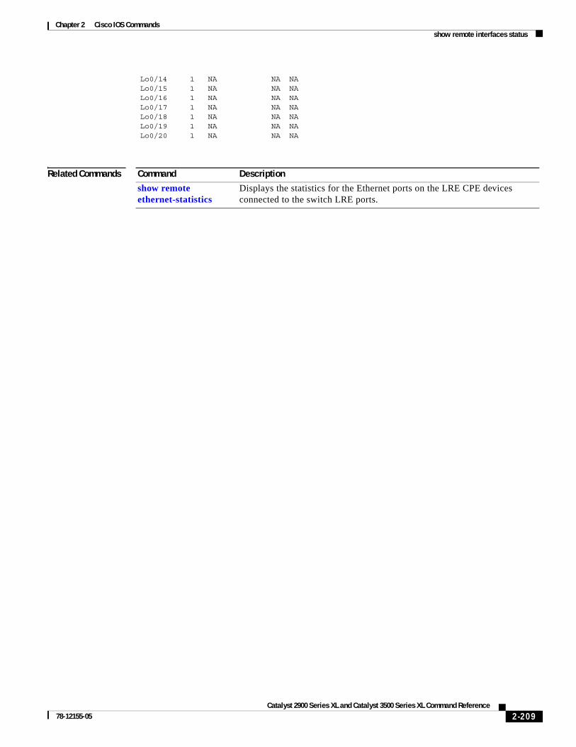
Chapter 2 Cisco IOS Commandsshow remote interfaces status
Lo0/14 1 NA NA NA Lo0/15 1 NA NA NA Lo0/16 1 NA NA NA Lo0/17 1 NA NA NA Lo0/18 1 NA NA NA Lo0/19 1 NA NA NA Lo0/20 1 NA NA NA
Related Commands Command Description
show remote ethernet-statistics
Displays the statistics for the Ethernet ports on the LRE CPE devices connected to the switch LRE ports.
2-209Catalyst 2900 Series XL and Catalyst 3500 Series XL Command Reference
78-12155-05

Chapter 2 Cisco IOS Commandsshow rps
show rpsUse the show rps user EXEC command to display the status of the Cisco Redundant Power System (RPS).
show rps [ | {begin | exclude | include} expression]
Syntax Description
Command Modes User EXEC
Command History
Examples This is an example of output from the show rps command. Table 2-3 describes the possible display output.
Switch> show rpsACTIVATED
| begin (Optional) Display begins with the line that matches the specified expression.
| exclude (Optional) Display excludes lines that match the specified expression.
| include (Optional) Display includes lines that match the specified expression.
expression Expression in the output to use as a reference point.
Release Modification
12.0(5)XU This command was first introduced.
Table 2-3 Show RPS Display Output Description
Display Description Switch RPS LED Color
NA The RPS is off or not installed. Off (all switch and RPS models)
ACTIVATED The internal power supply of the switch is down. The switch is operating through the RPS.
Blinking amber (3524-PWR switch connected to RPS 300)
Solid green (all Catalyst 2900 XL and Catalyst 3500 XL switches, except the 3524-PWR, connected to the Cisco RPS)
DEACTIVATED The RPS is connected, operational, and in standby mode. The switch is operating from its own internal power supply.
Solid green (3524-PWR switch connected to RPS 300)
Blinking green (all Catalyst 2900 XL and Catalyst 3500 XL switches, except the 3524-PWR, connected to the Cisco RPS)
2-210Catalyst 2900 Series XL and Catalyst 3500 Series XL Command Reference
78-12155-05

Chapter 2 Cisco IOS Commandsshow rps
FAULTY The RPS is connected but not operating correctly (faulty). One of the power supplies in the RPS could be powered down or a fan on the RPS could have failed.
Solid amber (all switch and RPS models)
NOT AVAILABLE (Catalyst 3524-PWR only)
The RPS is backing up another switch; power redundancy is lost.
Blinking green (3524-PWR switch connected to RPS 300)
Table 2-3 Show RPS Display Output Description (continued)
Display Description Switch RPS LED Color
2-211Catalyst 2900 Series XL and Catalyst 3500 Series XL Command Reference
78-12155-05

Chapter 2 Cisco IOS Commandsshow spanning-tree
show spanning-treeUse the show spanning-tree user EXEC command to display spanning-tree information for the specified spanning-tree instances.
show spanning-tree [brief] | [summary] | [vlan stp-list] | [interface interface-list] [ | {begin | exclude | include} expression]
Syntax Description
Command Modes User EXEC
Command History
Usage Guidelines If the variable stp-list is omitted, the command applies to the spanning-tree instance associated with VLAN 1.
Examples This is an example of output from the show spanning-tree command for VLAN 1:
Switch> show spanning-tree vlan 1Spanning tree 1 is executing the IEEE compatible Spanning Tree protocol Bridge Identifier has priority 49152, address 00b0.6476.08c0 Configured hello time 2, max age 20, forward delay 15 Current root has priority 32768, address 0001.42cd.a200 Root port is 31, cost of root path is 42 Topology change flag not set, detected flag not set, changes 1 Times: hold 1, topology change 35, notification 2 hello 2, max age 20, forward delay 15
brief Display a brief status of the spanning tree.
summary Display a summary of the spanning-tree states.
vlan stp-list (Optional) List of spanning-tree instances. Each spanning-tree instance is associated with a VLAN ID. Enter each VLAN ID separated by a space. Valid IDs are from 1 to 1005; do not enter leading zeros. Ranges are not supported.
interface interface-list List of ports for which spanning-tree information appears. Enter each port separated by a space. Ranges are not supported.
| begin (Optional) Display begins with the line that matches the specified expression.
| exclude (Optional) Display excludes lines that match the specified expression.
| include (Optional) Display includes lines that match the specified expression.
expression Expression in the output to use as a reference point.
Release Modification
11.2(8)SA3 This command was first introduced.
12.0(5)XW The brief and summary keywords were added.
12.0(5)WC5 The summary keyword was extended to show whether the BPDU guard feature is enabled or disabled.
2-212Catalyst 2900 Series XL and Catalyst 3500 Series XL Command Reference
78-12155-05

Chapter 2 Cisco IOS Commandsshow spanning-tree
Timers: hello 0, topology change 0, notification 0 Fast uplink switchover is enabled Stack port is GigabitEthernet0/1
Interface Fa0/1 (port 13) in Spanning tree 1 is down Port path cost 3100, Port priority 128 Designated root has priority 32768, address 0001.42cd.a200 Designated bridge has priority 49152, address 00b0.6476.08c0 Designated port is 13, path cost 42 Timers: message age 0, forward delay 0, hold 0 BPDU: sent 0, received 0<output truncated>
This is an example of output from the show spanning-tree interface command for port 3:
Switch> show spanning-tree interface fa0/3
Interface Fa0/3 (port 3) in Spanning tree 1 is down Port path cost 100, Port priority 128 Designated root has priority 6000, address 0090.2bba.7a40 Designated bridge has priority 32768, address 00e0.1e9f.4abf Designated port is 3, path cost 410 Timers: message age 0, forward delay 0, hold 0 BPDU: sent 0, received 0
This is an example of output from the show spanning-tree summary command:
Switch> show spanning-tree summaryUplinkFast is enabledPortFast BPDU Guard is disabledStack port is GigabitEthernet0/1
Name Blocking Listening Learning Forwarding STP Active-------------------- -------- --------- -------- ---------- ----------VLAN1 13 0 0 1 14VLAN2 1 0 0 1 2VLAN3 1 0 0 1 2<output truncated>
Related Commands Command Description
spanning-tree Enables STP on a VLAN.
spanning-tree forward-time Specifies the forwarding-time for the specified spanning-tree instances.
spanning-tree max-age Changes the interval between messages that the spanning tree receives from the root switch.
spanning-tree port-priority Configures a port priority, which is used when two switches tie for position as the root switch.
spanning-tree protocol Specifies the STP version to be used for specified spanning-tree instances.
2-213Catalyst 2900 Series XL and Catalyst 3500 Series XL Command Reference
78-12155-05

Chapter 2 Cisco IOS Commandsshow tacacs
show tacacsUse the show tacacs user EXEC command to display various Terminal Access Controller Access Control System Plus (TACACS+) server statistics.
show tacacs [ | {begin | exclude | include} expression]
Syntax Description
Command Modes User EXEC
Command History
Examples This is an example of output from the show tacacs command:
Switch> show tacacs
Server:172.20.128.113/49:opens=4 closes=4 aborts=0 errors=0 packets in=6 packets out=6 no connection
| begin (Optional) Display begins with the line that matches the specified expression.
| exclude (Optional) Display excludes lines that match the specified expression.
| include (Optional) Display includes lines that match the specified expression.
expression Expression in the output to use as a reference point.
Release Modification
11.2(8)SA6 This command was first introduced.
2-214Catalyst 2900 Series XL and Catalyst 3500 Series XL Command Reference
78-12155-05
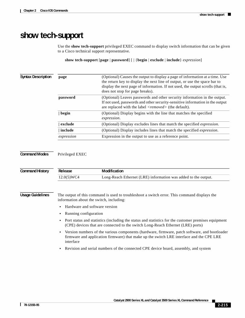
Chapter 2 Cisco IOS Commandsshow tech-support
show tech-supportUse the show tech-support privileged EXEC command to display switch information that can be given to a Cisco technical support representative.
show tech-support [page | password] [ | {begin | exclude | include} expression]
Syntax Description
Command Modes Privileged EXEC
Command History
Usage Guidelines The output of this command is used to troubleshoot a switch error. This command displays the information about the switch, including:
• Hardware and software version
• Running configuration
• Port status and statistics (including the status and statistics for the customer premises equipment (CPE) devices that are connected to the switch Long-Reach Ethernet (LRE) ports)
• Version numbers of the various components (hardware, firmware, patch software, and bootloader firmware and application firmware) that make up the switch LRE interface and the CPE LRE interface
• Revision and serial numbers of the connected CPE device board, assembly, and system
page (Optional) Causes the output to display a page of information at a time. Use the return key to display the next line of output, or use the space bar to display the next page of information. If not used, the output scrolls (that is, does not stop for page breaks).
password (Optional) Leaves passwords and other security information in the output. If not used, passwords and other security-sensitive information in the output are replaced with the label <removed> (the default).
| begin (Optional) Display begins with the line that matches the specified expression.
| exclude (Optional) Display excludes lines that match the specified expression.
| include (Optional) Display includes lines that match the specified expression.
expression Expression in the output to use as a reference point.
Release Modification
12.0(5)WC4 Long-Reach Ethernet (LRE) information was added to the output.
2-215Catalyst 2900 Series XL and Catalyst 3500 Series XL Command Reference
78-12155-05

Chapter 2 Cisco IOS Commandsshow tech-support
Examples This is an example of output from the show tech-support command:
Switch# show tech-support
------------------ show version ------------------
Cisco Internetwork Operating System Software IOS (tm) C2900xl Software (C2900xl-C3H2L9S-M), Version 12.0(5)WC4, RELEASE SOFT)Copyright (c) 1986-2002 by cisco Systems, Inc.Compiled Tue 02-Apr-02 12:57 by antoninoImage text-base: 0x00003000, data-base: 0x0035AF3C
ROM: Bootstrap program is C2900xl boot loader
2900LRE-239-34 uptime is 2 days, 23 hours, 24 minutesSystem returned to ROM by reloadSystem image file is "flash:c2900xl-c3h2l9s-mz.120-5.WC4.bin"
cisco WS-C2924-LRE-XL (PowerPC403) processor (revision 0x01) with 16384K/1024K .Processor board ID FAA0514E08L, with hardware revision 0x00Last reset from warm-reset
Processor is running Enterprise Edition SoftwareCluster command switch capableCluster member switch capable4 FastEthernet/IEEE 802.3 interface(s)24 LongReachEthernet/VDSL interfaces(s) 32K bytes of flash-simulated non-volatile configuration memory.Base ethernet MAC Address: 00:04:DD:7B:DE:C0Motherboard assembly number: 73-5663-06 ------------------ show running-config ------------------
Building configuration...
Current configuration:!version 12.0no service padservice timestamps debug uptimeservice timestamps log datetimeno service password-encryptionservice sequence-numbers!hostname 2900LRE-239-34!enable secret level 7 5 <removed>!!no spanning-tree vlan 121no spanning-tree vlan 126no spanning-tree vlan 128
2-216Catalyst 2900 Series XL and Catalyst 3500 Series XL Command Reference
78-12155-05
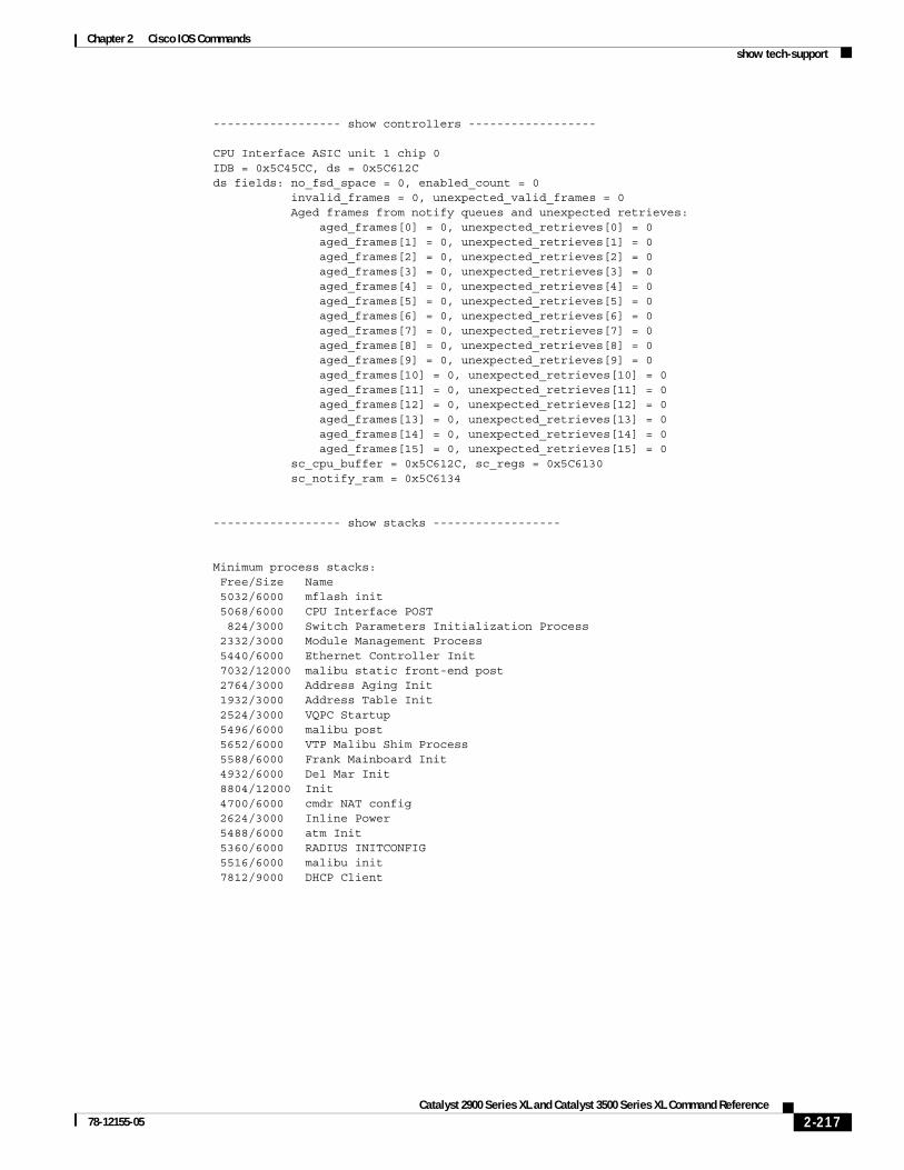
Chapter 2 Cisco IOS Commandsshow tech-support
------------------ show controllers ------------------
CPU Interface ASIC unit 1 chip 0IDB = 0x5C45CC, ds = 0x5C612Cds fields: no_fsd_space = 0, enabled_count = 0 invalid_frames = 0, unexpected_valid_frames = 0 Aged frames from notify queues and unexpected retrieves: aged_frames[0] = 0, unexpected_retrieves[0] = 0 aged_frames[1] = 0, unexpected_retrieves[1] = 0 aged_frames[2] = 0, unexpected_retrieves[2] = 0 aged_frames[3] = 0, unexpected_retrieves[3] = 0 aged_frames[4] = 0, unexpected_retrieves[4] = 0 aged_frames[5] = 0, unexpected_retrieves[5] = 0 aged_frames[6] = 0, unexpected_retrieves[6] = 0 aged_frames[7] = 0, unexpected_retrieves[7] = 0 aged_frames[8] = 0, unexpected_retrieves[8] = 0 aged_frames[9] = 0, unexpected_retrieves[9] = 0 aged_frames[10] = 0, unexpected_retrieves[10] = 0 aged_frames[11] = 0, unexpected_retrieves[11] = 0 aged_frames[12] = 0, unexpected_retrieves[12] = 0 aged_frames[13] = 0, unexpected_retrieves[13] = 0 aged_frames[14] = 0, unexpected_retrieves[14] = 0 aged_frames[15] = 0, unexpected_retrieves[15] = 0 sc_cpu_buffer = 0x5C612C, sc_regs = 0x5C6130 sc_notify_ram = 0x5C6134 ------------------ show stacks ------------------
Minimum process stacks: Free/Size Name 5032/6000 mflash init 5068/6000 CPU Interface POST 824/3000 Switch Parameters Initialization Process 2332/3000 Module Management Process 5440/6000 Ethernet Controller Init 7032/12000 malibu static front-end post 2764/3000 Address Aging Init 1932/3000 Address Table Init 2524/3000 VQPC Startup 5496/6000 malibu post 5652/6000 VTP Malibu Shim Process 5588/6000 Frank Mainboard Init 4932/6000 Del Mar Init 8804/12000 Init 4700/6000 cmdr NAT config 2624/3000 Inline Power 5488/6000 atm Init 5360/6000 RADIUS INITCONFIG 5516/6000 malibu init 7812/9000 DHCP Client
2-217Catalyst 2900 Series XL and Catalyst 3500 Series XL Command Reference
78-12155-05

Chapter 2 Cisco IOS Commandsshow tech-support
------------------ show interfaces ------------------
VLAN1 is up, line protocol is up Hardware is CPU Interface, address is 0004.dd7b.dec0 (bia 0004.dd7b.dec0) Internet address is 172.20.139.239/27 MTU 1500 bytes, BW 10000 Kbit, DLY 1000 usec, reliability 255/255, txload 1/255, rxload 1/255 Encapsulation ARPA, loopback not set ARP type: ARPA, ARP Timeout 04:00:00 Last input 00:00:00, output 00:00:00, output hang never Last clearing of "show interface" counters never Queueing strategy: fifo Output queue 0/40, 0 drops; input queue 0/75, 0 drops 5 minute input rate 0 bits/sec, 0 packets/sec 5 minute output rate 0 bits/sec, 0 packets/sec 77972 packets input, 6033758 bytes, 0 no buffer Received 17299 broadcasts, 0 runts, 0 giants, 0 throttles 0 input errors, 0 CRC, 0 frame, 0 overrun, 0 ignored 0 input packets with dribble condition detected 77411 packets output, 22057375 bytes, 0 underruns 0 output errors, 0 collisions, 0 interface resets 0 babbles, 0 late collision, 0 deferred 0 lost carrier, 0 no carrier 0 output buffer failures, 0 output buffers swapped outt
------------------ show controllers lre version ------------------
--- SWITCH --- ------------ CPE -----------Interface Hw Sw Patch Hw Sw Patch Boot AppLo0/1 32 B4 50 32 B4 50 NA NALo0/2 32 B4 50 32 B4 50 NA NALo0/3 32 B4 50 32 B4 50 NA NALo0/4 32 B4 50 32 B4 50 NA NALo0/5 32 B4 50 00 00 00 NA NALo0/6 32 B4 50 32 B4 51 NA NALo0/7 32 B4 50 32 B4 51 NA NALo0/8 32 B4 50 32 B4 51 NA NALo0/9 32 B4 50 32 B4 50 NA NALo0/10 32 B4 50 00 00 00 NA NALo0/11 32 B4 50 00 00 00 NA NALo0/12 32 B4 50 00 00 00 NA NALo0/13 32 B4 50 32 B4 51 1.01 0.30Lo0/14 32 B4 50 00 00 00 NA NALo0/15 32 B4 50 32 B4 50 NA NALo0/16 32 B4 50 00 00 00 NA NALo0/17 32 B4 50 00 00 00 NA NALo0/18 32 B4 50 00 00 00 NA NALo0/19 32 B4 50 00 00 00 NA NALo0/20 32 B4 50 00 00 00 NA NA
2-218Catalyst 2900 Series XL and Catalyst 3500 Series XL Command Reference
78-12155-05

Chapter 2 Cisco IOS Commandsshow tech-support
------------------ show controllers lre version mfg ------------------
CPE Manufacturer Information
Lo0/1 Assembly Revision Number:05 Model Number :CISCO575-LRE Model Revision Number :Board Assembly Number :73-5579-08 Board Serial Number :FAA05160569 System Serial Number :FAA0516E0KL
Lo0/2 Assembly Revision Number:05 Model Number :SUDHI-575Model Revision Number :Board Assembly Number :73-5579-08 Board Serial Number :FAA05160561 System Serial Number :FAA0516E0KM
Lo0/3 Assembly Revision Number:05 Model Number :NON-CERT-575Model Revision Number :Board Assembly Number :73-5579-08 Board Serial Number :FAA05160576
------------------ show controllers lre status profile ------------------
Port Link Uptime Profile DSRate USRate Fail------ ---- -------- ------------------- ------ ------ ----Lo0/1 UP 2d23h LRE-10 12.500 12.500 0Lo0/2 UP 2d23h LRE-10 4.167 1.563 0Lo0/3 UP 2d23h LRE-10 4.167 1.563 0Lo0/4 UP 2d23h LRE-10 4.167 1.563 0Lo0/5 DOWN 00:00:00 LRE-10 0.000 0.000 0Lo0/6 UP 2d23h LRE-10 4.167 1.563 0Lo0/7 UP 2d23h LRE-10 4.167 1.563 0Lo0/8 UP 2d23h LRE-10 4.167 1.563 0Lo0/9 UP 2d23h LRE-10 4.167 1.563 0Lo0/10 DOWN 00:00:00 LRE-10 0.000 0.000 0Lo0/11 DOWN 00:00:00 LRE-10 0.000 0.000 0Lo0/12 DOWN 00:00:00 LRE-10 0.000 0.000 0Lo0/13 UP 2d23h LRE-10 12.500 12.500 0Lo0/14 DOWN 00:00:00 LRE-10 0.000 0.000 0Lo0/15 UP 2d23h LRE-10 4.167 1.563 0Lo0/16 DOWN 00:00:00 LRE-10 0.000 0.000 0Lo0/17 DOWN 00:00:00 LRE-10 0.000 0.000 0Lo0/18 DOWN 00:00:00 LRE-10 0.000 0.000 0Lo0/19 DOWN 00:00:00 LRE-10 0.000 0.000 0
2-219Catalyst 2900 Series XL and Catalyst 3500 Series XL Command Reference
78-12155-05

Chapter 2 Cisco IOS Commandsshow tech-support
------------------ show controllers lre status fsm ------------------
Port Link Current State Uptime Timer0 Timer1 Timer2 PFC------ ---- ------------------------ -------- -------- -------- -------- ---Lo0/1 UP (5)PROFILE_LINKUP 2d23h Stopped Stopped Stopped 0 Lo0/2 UP (3)MODEZERO_UNSUPPORTED 2d23h Stopped Stopped Stopped 0 Lo0/3 UP (3)MODEZERO_UNSUPPORTED 2d23h Stopped Stopped Stopped 0 Lo0/4 UP (3)MODEZERO_UNSUPPORTED 2d23h Stopped Stopped Stopped 0 Lo0/5 DOWN (2)MODEZERO_APPLIED 00:00:00 Stopped Stopped Stopped 0 Lo0/6 UP (3)MODEZERO_UNSUPPORTED 2d23h Stopped Stopped Stopped 0 Lo0/7 UP (3)MODEZERO_UNSUPPORTED 2d23h Stopped Stopped Stopped 0 Lo0/8 UP (3)MODEZERO_UNSUPPORTED 2d23h Stopped Stopped Stopped 0 Lo0/9 UP (3)MODEZERO_UNSUPPORTED 2d23h Stopped Stopped Stopped 0 Lo0/10 DOWN (2)MODEZERO_APPLIED 00:00:00 Stopped Stopped Stopped 0 Lo0/11 DOWN (2)MODEZERO_APPLIED 00:00:00 Stopped Stopped Stopped 0 Lo0/12 DOWN (2)MODEZERO_APPLIED 00:00:00 Stopped Stopped Stopped 0 Lo0/13 UP (5)PROFILE_LINKUP 2d23h Stopped Stopped Stopped 0 Lo0/14 DOWN (2)MODEZERO_APPLIED 00:00:00 Stopped Stopped Stopped 0 Lo0/15 UP (3)MODEZERO_UNSUPPORTED 2d23h Stopped Stopped Stopped 0 Lo0/16 DOWN (2)MODEZERO_APPLIED 00:00:00 Stopped Stopped Stopped 0 Lo0/17 DOWN (2)MODEZERO_APPLIED 00:00:00 Stopped Stopped Stopped 0 Lo0/18 DOWN (2)MODEZERO_APPLIED 00:00:00 Stopped Stopped Stopped 0 Lo0/19 DOWN (2)MODEZERO_APPLIED 00:00:00 Stopped Stopped Stopped 0
------------------ show controllers lre status link ------------------
Port Link SNR RS Errs CPE-Tx Sw-AGC-Gain Interleaver PMD-S (dB) (dBm/Hz) (dB) Rx-Bsz Tx-Bsz ------ ---- ---- ----------- -------- ----------- ------------- -----Lo0/1 UP 28 0 - 91.9 26.8 16 16 0x04Lo0/2 UP 35 0 - 85.9 23.7 0 0 0x04Lo0/3 UP 35 0 - 85.9 23.3 0 0 0x04Lo0/4 UP 35 0 - 85.9 23.3 0 0 0x04Lo0/5 DOWN 0 0 0.0 0.0 0 0 0x04Lo0/6 UP 35 0 - 85.9 21.1 0 0 0x04Lo0/7 UP 35 0 - 85.9 21.1 0 0 0x04Lo0/8 UP 35 0 - 85.9 21.1 0 0 0x04Lo0/9 UP 35 0 - 85.9 21.1 0 0 0x04Lo0/10 DOWN 0 0 0.0 0.0 0 0 0x04Lo0/11 DOWN 0 0 0.0 0.0 0 0 0x04Lo0/12 DOWN 0 0 0.0 0.0 0 0 0x04Lo0/13 UP 28 0 - 91.9 23.8 16 16 0x04Lo0/14 DOWN 0 0 0.0 0.0 0 0 0x04Lo0/15 UP 35 0 - 85.9 23.7 0 0 0x04Lo0/16 DOWN 0 0 0.0 0.0 0 0 0x04Lo0/17 DOWN 0 0 0.0 0.0 0 0 0x04Lo0/18 DOWN 0 0 0.0 0.0 0 0 0x04
2-220Catalyst 2900 Series XL and Catalyst 3500 Series XL Command Reference
78-12155-05

Chapter 2 Cisco IOS Commandsshow tech-support
------------------ show controllers lre status eft local ------------------
Port 8C70 8C71 SNR RS Errs TxPwr SwAGCGain Fail 8214 8216 8217 8218 SwRst------ ---- ---- --- ----------- ----- --------- ---- ---- ---- ---- ---- -----Lo0/1 00 AE 28 0 - 57.0 26.8 0 51 83 2D D7 0Lo0/2 00 AE 35 0 - 54.3 23.7 0 51 83 2E CF 0Lo0/3 00 AE 35 0 - 54.3 23.3 0 50 83 30 CF 0Lo0/4 00 AE 35 0 - 54.3 23.3 0 50 83 2E CF 0Lo0/5 00 00 0 0 0.0 0.0 0 5A C0 24 E4 0Lo0/6 00 AE 35 0 - 54.3 21.1 0 4B 83 2F CF 0Lo0/7 00 AE 35 0 - 54.3 21.1 0 4B 83 2F CF 0Lo0/8 00 AE 35 0 - 54.3 21.1 0 4B 83 2F CF 0Lo0/9 00 AE 35 0 - 54.3 21.1 0 4B 83 2E CF 0Lo0/10 00 00 0 0 0.0 0.0 0 5A C4 20 EE 0Lo0/11 00 00 0 0 0.0 0.0 0 5A E8 2A E4 0Lo0/12 00 00 0 0 0.0 0.0 0 5A B0 20 ED 0Lo0/13 00 AE 28 0 - 57.0 23.8 0 4A 83 2F D7 0Lo0/14 00 02 0 0 0.0 0.0 0 5A DC 3B DC 0Lo0/15 00 AE 35 0 - 54.3 23.7 0 51 80 2F CF 0Lo0/16 00 00 0 0 0.0 0.0 0 5A E4 23 E4 0Lo0/17 00 00 0 0 0.0 0.0 0 5A 94 20 EC 0Lo0/18 00 00 0 0 0.0 0.0 0 5A CC 30 E4 0Lo0/19 00 00 0 0 0.0 0.0 0 5A FC 20 EE 0
------------------ show controllers lre status eft remote ------------------
Port 8C70 8C71 SNR RS Errs TxPwr SwAGCGain Fail 8214 8216 8217 8218 SwRst------ ---- ---- --- ----------- ----- --------- ---- ---- ---- ---- ---- -----Lo0/1 94 AE 42 0 - 91.9 - 3.7 0 0A 83 27 D7 225Lo0/2 94 AE 44 0 - 85.9 - 6.9 0 0D 80 2B CF 69Lo0/3 94 AE 44 0 - 85.9 - 7.3 0 0C 80 2B CF 186Lo0/4 94 AE 41 0 - 85.9 - 7.3 0 0C 83 2C CF 158Lo0/5 00 00 0 0 0.0 0.0 0 00 00 00 00 0Lo0/6 D4 AE 44 0 - 85.9 - 8.6 0 06 80 2D CF 95Lo0/7 D4 AE 44 0 - 85.9 - 9.9 0 06 80 2C CF 185Lo0/8 D4 AE 44 0 - 85.9 - 8.1 0 07 80 2D CF 206Lo0/9 D4 AE 44 0 - 85.9 - 10.3 0 05 83 2C CF 214Lo0/10 00 00 0 0 0.0 0.0 0 00 00 00 00 0Lo0/11 00 00 0 0 0.0 0.0 0 00 00 00 00 0Lo0/12 00 00 0 0 0.0 0.0 0 00 00 00 00 0Lo0/13 D4 AE 42 0 - 91.9 - 5.9 0 05 80 2B D7 145Lo0/14 00 00 0 0 0.0 0.0 0 00 00 00 00 0Lo0/15 94 AE 44 0 - 85.9 - 7.7 0 0B 83 2B CF 118Lo0/16 00 00 0 0 0.0 0.0 0 00 00 00 00 0Lo0/17 00 00 0 0 0.0 0.0 0 00 00 00 00 0Lo0/18 00 00 0 0 0.0 0.0 0 00 00 00 00 0Lo0/19 00 00 0 0 0.0 0.0 0 00 00 00 00 0
2-221Catalyst 2900 Series XL and Catalyst 3500 Series XL Command Reference
78-12155-05

Chapter 2 Cisco IOS Commandsshow tech-support
------------------ show process memory ------------------
Total: 11655816, Used: 2640180, Free: 9015636 PID TTY Allocated Freed Holding Getbufs Retbufs Process 0 0 50304 1504 463500 0 0 *Init* 0 0 2092 94258192 2092 0 0 *Sched* 0 0 146444420 153682876 1418364 4415372 3911376 *Dead* 1 0 268 268 3836 0 0 Load Meter 2 0 0 0 6900 0 0 LRE Link Monitor 3 0 0 2364 6836 0 0 Check heaps 4 0 20248 0 27084 0 0 Chunk Manager 5 0 93528 1224 13052 26520 3448 Pool Manager 6 0 268 268 6836 0 0 Timers 7 0 1216 140 7912 0 0 Entity MIB API 8 0 0 0 6836 0 0 HC Counter Timer 9 0 348 168 7016 0 0 ARP Input 10 0 0 0 3836 0 0 RAM Access (dm 0 11 0 96 0 6932 0 0 Critical Bkgnd 12 0 27212 752 16220 0 0 Net Background 13 0 364 268 12932 0 0 Logger 14 0 13256 916 6924 0 0 TTY Background 15 0 242431300 231953936 6836 1560 21672 Per-Second Jobs 16 0 192 0 7028 0 0 Net Input 17 0 268 268 6836 0 0 Compute load avg
------------------ show process cpu ------------------
CPU utilization for five seconds: 52%/8%; one minute: 60%; five minutes: 59% PID Runtime(ms) Invoked uSecs 5Sec 1Min 5Min TTY Process 1 895 51504 17 0.00% 0.00% 0.00% 0 Load Meter 2 32270190 20722247 1557 6.83% 6.33% 6.57% 0 LRE Link Monitor 3 133858 28515 4694 0.00% 0.04% 0.00% 0 Check heaps 4 3 1 3000 0.00% 0.00% 0.00% 0 Chunk Manager 5 14 43 325 0.00% 0.00% 0.00% 0 Pool Manager 6 0 2 0 0.00% 0.00% 0.00% 0 Timers 7 0 2 0 0.00% 0.00% 0.00% 0 Entity MIB API 8 5312 64314 82 0.00% 0.00% 0.00% 0 HC Counter Timer 9 3719 8031 463 0.00% 0.00% 0.00% 0 ARP Input 10 0 1 0 0.00% 0.00% 0.00% 0 RAM Access (dm 0 11 0 1 0 0.00% 0.00% 0.00% 0 Critical Bkgnd 12 16913 222337 76 0.00% 0.00% 0.00% 0 Net Background 13 8 18 444 0.00% 0.00% 0.00% 0 Logger 14 8462 254794 33 0.00% 0.00% 0.00% 0 TTY Background 15 709384 758557 935 0.04% 0.15% 0.17% 0 Per-Second Jobs 16 0 7 0 0.00% 0.00% 0.00% 0 Net Input 17 2478 51504 48 0.00% 0.00% 0.00% 0 Compute load avg 18 72442 4293 16874 0.00% 0.01% 0.00% 0 Per-minute Jobs 19 58575 1490 39312 0.00% 0.00% 0.00% 0 LRE Monitor 20 6998145 16506781 423 2.33% 1.78% 1.84% 0 LED Control Proc
2-222Catalyst 2900 Series XL and Catalyst 3500 Series XL Command Reference
78-12155-05

Chapter 2 Cisco IOS Commandsshow tech-support
------------------ show buffers ------------------
Buffer elements: 500 in free list (500 max allowed) 4962874 hits, 0 misses, 0 created
Public buffer pools:Small buffers, 104 bytes (total 49, permanent 25): 40 in free list (20 min, 60 max allowed) 70361936 hits, 291 misses, 600 trims, 624 created 0 failures (0 no memory)Middle buffers, 600 bytes (total 18, permanent 15): 17 in free list (10 min, 30 max allowed) 339217 hits, 8 misses, 21 trims, 24 created 0 failures (0 no memory)Big buffers, 1524 bytes (total 11, permanent 5): 10 in free list (5 min, 10 max allowed) 30029 hits, 760 misses, 2274 trims, 2280 created 0 failures (0 no memory)VeryBig buffers, 4520 bytes (total 0, permanent 0): 0 in free list (0 min, 10 max allowed) 3 hits, 1 misses, 2 trims, 2 created 0 failures (0 no memory)Large buffers, 5024 bytes (total 0, permanent 0):
2-223Catalyst 2900 Series XL and Catalyst 3500 Series XL Command Reference
78-12155-05

Chapter 2 Cisco IOS Commandsshow udld
show udldUse the show udld user EXEC command to display UniDirectional Link Detection (UDLD) status for all ports or the specified port.
show udld [interface-id] [ | {begin | exclude | include} expression]
Syntax Description
Command Modes User EXEC
Command History
Examples This is an example of output from the show udld fa0/11 command. In this display, UDLD is enabled on both ends of the link, and UDLD detects that the link is bidirectional. Table 2-4 describes the fields in this display.
Switch> show udld fa0/11Interface Fa0/11Port enable configuration setting: Follows global settingOperational enable state: EnabledCurrent bidirectional state: BidirectionalMessage interval: 60Message timer: 38Current operational state: AdvertisementTime out interval: 5Time out timer: 0Restart counter: 0Neighbors counter: 1Probe counter: 0No multiple neighbors detectedCurrent pool id: 1 --- Cache entry 1 (0x69D8E4) Device name: aunguyen-1.cisco.com Device MAC address: 00:E0:1E:9F:85:80 Port ID: Fa1/1 Expiration time: 159 Cache device ID: 1 Resynch flag clear Current neighbor state: Bidirectional Most recent message type received: Probe Message interval: 5
interface-id (Optional) ID of the module and port or a VLAN ID. Valid IDs are from 1 to 1000.
| begin (Optional) Display begins with the line that matches the specified expression.
| exclude (Optional) Display excludes lines that match the specified expression.
| include (Optional) Display includes lines that match the specified expression.
expression Expression in the output to use as a reference point.
Release Modification
12.0(5)XU This command was first introduced.
2-224Catalyst 2900 Series XL and Catalyst 3500 Series XL Command Reference
78-12155-05

Chapter 2 Cisco IOS Commandsshow udld
Neighbor echo 1 device: 00:50:0F:08:A4:00 Neighbor echo 1 port: Fa0/11
Table 2-4 Show UDLD Field Descriptions
Field Description
Interface The interface on the local device configured for UDLD.
Port enable configuration setting
How UDLD is configured on the port. If UDLD is enabled or disabled, the port enable configuration setting is the same as operational enable state. Otherwise, the enable operational setting depends on the global enable setting.
Operational enable state Operational state that indicates whether UDLD is actually running on this port.
Current bidirectional state The bidirectional state of the link. An unknown state appears if the link is down or if it is connected to an UDLD-incapable device. A bidirectional state appears if the link is a normal two-way connection to a UDLD-capable device. All other values mean miswiring.
Message interval How often advertisement messages are sent from the local device. Measured in seconds.
Message timer The length of time before the next advertisement is sent from the local device. Measured in seconds.
Current operational state The current phase of the UDLD state machine. For a normal bidirectional link, the state machine is usually in the Advertisement phase.
Time out interval The time period, in seconds, that UDLD waits for echoes from a neighbor device during the detection window.
Time out timer The remaining time in seconds in the detection window. This setting is meaningful only if UDLD is in the detection phase.
Restart counter The number of times UDLD sends probe messages in the detection phase.
Neighbors counter The number of neighbors detected. For point-to-point links, this value should always be one. It is greater than one only when the port is connected to a hub.
Probe counter The remaining number of probe messages to send in the detection window. This setting is meaningful only if UDLD is in the detection phase.
Current pool id An internal index number on the local device.
Cache entry 1 Information from the first cache entry, which contains a copy of echo information received from the neighbor.
Device name The neighbor device name.
Device MAC address The neighbor MAC address.
Port ID The neighbor port ID enabled for UDLD.
Expiration time The amount of time in seconds remaining before this cache entry is aged out.
Cache device ID The ID of the cache device.
2-225Catalyst 2900 Series XL and Catalyst 3500 Series XL Command Reference
78-12155-05

Chapter 2 Cisco IOS Commandsshow udld
Related Commands
Resynch flag clear There are no outstanding requests from neighbors to resynchronize cache data.
Current neighbor state The neighbor’s current state. If both the local and neighbor devices are running UDLD normally, the neighbor state and local state should be bidirectional. If the link is down or the neighbor is not UDLD-capable, no cache entries are displayed.
Most recent message type received
The type of message received from the neighbor.
Message interval The rate, in seconds, at which the neighbor is sending advertisement messages.
Neighbor echo 1 device The MAC address of the neighbors neighbor from which the echo originated.
Neighbor echo 1 port The port ID of the neighbor from which the echo originated.
Table 2-4 Show UDLD Field Descriptions (continued)
Field Description
Command Description
udld Enables UDLD on a port.
udld enable Enables UDLD on all ports on the switch.
udld reset Resets any interface that has been shut down by UDLD.
2-226Catalyst 2900 Series XL and Catalyst 3500 Series XL Command Reference
78-12155-05

Chapter 2 Cisco IOS Commandsshow version
show versionUse the show version user EXEC command to display version information for the hardware and firmware.
show version [ | {begin | exclude | include} expression]
Syntax Description
The command has no arguments.
Command Modes User EXEC
Command History
Examples This is an example of output from the show version command:
Switch> show version
Cisco Internetwork Operating System Technology SoftwareIOS Technology(tm) C3500XL Software (C3500XL-C3H2S-M), Version 12.0Copyright (c) 1986-1998 by cisco Systems, Inc.Compiled Mon 22-Nov-99 10:51 by mollynImage text-base: 0x00003000, data-base: 0x0031B6B4
ROM: Bootstrap program is C3500XL boot loader
Switch uptime is 1 hour, 32 minutesSystem returned to ROM by reloadSystem image file is "flash:c3500XL-c3h2s-mz-120.0.0.29-XU.bin"
cisco WS-C3524-XL (PowerPC403) processor (revision 0x01) with 8192K/1024K bytesof memory.Processor board ID 0x12, with hardware revision 0x00Last reset from warm-reset
Processor is running Enterprise Edition SoftwareCluster command switch capableCluster member switch capable24 FastEthernet/IEEE 802.3 interface(s) 2 Gigabit Ethernet/IEEE 802.3 interface(s)
32K bytes of flash-simulated non-volatile configuration memory.Base ethernet MAC Address: 00:D0:79:6D:2F:00Motherboard assembly number: 73-3904-08
| begin (Optional) Display begins with the line that matches the specified expression.
| exclude (Optional) Display excludes lines that match the specified expression.
| include (Optional) Display includes lines that match the specified expression.
expression Expression in the output to use as a reference point.
Release Modification
11.2(8)SA This command was first introduced.
2-227Catalyst 2900 Series XL and Catalyst 3500 Series XL Command Reference
78-12155-05

Chapter 2 Cisco IOS Commandsshow version
Power supply part number: 34-0851-02Motherboard serial number: FAA03269NLKPower supply serial number: PHI031200D2Model revision number: A0Model number: WS-C3524-XL-ASystem serial number: FAA0328K01GConfiguration register is 0xF
2-228Catalyst 2900 Series XL and Catalyst 3500 Series XL Command Reference
78-12155-05

Chapter 2 Cisco IOS Commandsshow vlan
show vlanUse the show vlan user EXEC command to display the parameters for all configured VLANs or one VLAN (if the VLAN ID or name is specified) in the administrative domain.
show vlan [brief | id vlan-id | name vlan-name] [ | {begin | exclude | include} expression]
Syntax Description
Command Modes User EXEC
Command History
Examples This is an example of output from the show vlan command:
Switch> show vlanVLAN Name Status Ports---- -------------------------------- --------- -------------------------------1 default active Fa0/1, Fa0/2, Fa0/3, Fa0/4, Fa0/5, Fa0/6, Fa0/7, Fa0/8, Fa0/9, Fa0/10, Fa0/11, Fa0/12, Fa0/13, Fa0/14, Fa0/15, Fa0/16, Fa0/17, Fa0/18, Fa0/19, Fa0/20, Fa0/21, Fa0/22, Fa0/23, Fa0/24, Gi0/1, Gi0/21002 fddi-default active 1003 token-ring-default active 1004 fddinet-default active 1005 trnet-default active
VLAN Type SAID MTU Parent RingNo BridgeNo Stp Trans1 Trans2---- ----- ---------- ----- ------ ------ -------- ---- ------ ------1 enet 100001 1500 - - - - 1002 10036 fdnet 100006 1500 - - - ieee 0 07 trnet 100007 1500 - - 5 ieee 0 01002 fddi 101002 1500 - - - - 1 1003
brief (Optional) Display one line for each VLAN with the VLAN name, status, and its ports.
id vlan-id (Optional) ID of the VLAN displayed. Valid IDs are from 1 to 1005; do not enter leading zeros.
name vlan-name (Optional) Name of the VLAN displayed. The VLAN name is an ASCII string from 1 to 32 characters.
| begin (Optional) Display begins with the line that matches the specified expression.
| exclude (Optional) Display excludes lines that match the specified expression.
| include (Optional) Display includes lines that match the specified expression.
expression Expression in the output to use as a reference point.
Release Modification
11.2(8)SA3 This command was first introduced.
11.2(8)SA4 The name vlan-name keywords were added.
2-229Catalyst 2900 Series XL and Catalyst 3500 Series XL Command Reference
78-12155-05

Chapter 2 Cisco IOS Commandsshow vlan
1003 tr 101003 1500 1005 3276 - - 1 10021004 fdnet 101004 1500 - - 1 ibm 0 01005 trnet 101005 1500 - - 15 ibm 0 0
This is an example of output from the show vlan brief command:
Switch> show vlan brief
VLAN Name Status Ports---- -------------------------------- --------- -------------------------------1 default active Fa0/1, Fa0/2, Fa0/5, Fa0/6, Fa0/7, Fa0/8, Fa0/9, Fa0/10, Fa0/11, Fa0/12, Fa0/13, Fa0/14, Fa0/15, Fa0/16, Fa1/1, Fa1/2, Fa1/3, Fa1/4, Fa2/3, Fa2/42 VLAN0002 active3 VLAN0003 active6 VLAN0006 active7 VLAN0007 active1002 fddi-default active1003 token-ring-default active1004 fddinet-default active1005 trnet-default active
This is an example of output from the show vlan id 6 or show vlan name VLAN006 command:
Switch> show vlan id 6
VLAN Name Status Ports---- -------------------------------- --------- -------------------------------6 VLAN0006 active
VLAN Type SAID MTU Parent RingNo BridgeNo Stp Trans1 Trans2---- ----- ---------- ----- ------ ------ -------- ---- ------ ------6 fdnet 100006 1500 - - - ieee 0 0
Related Commands Command Description
switchport mode Configures the VLAN membership mode of a port.
vlan Configures VLAN characteristics.
2-230Catalyst 2900 Series XL and Catalyst 3500 Series XL Command Reference
78-12155-05
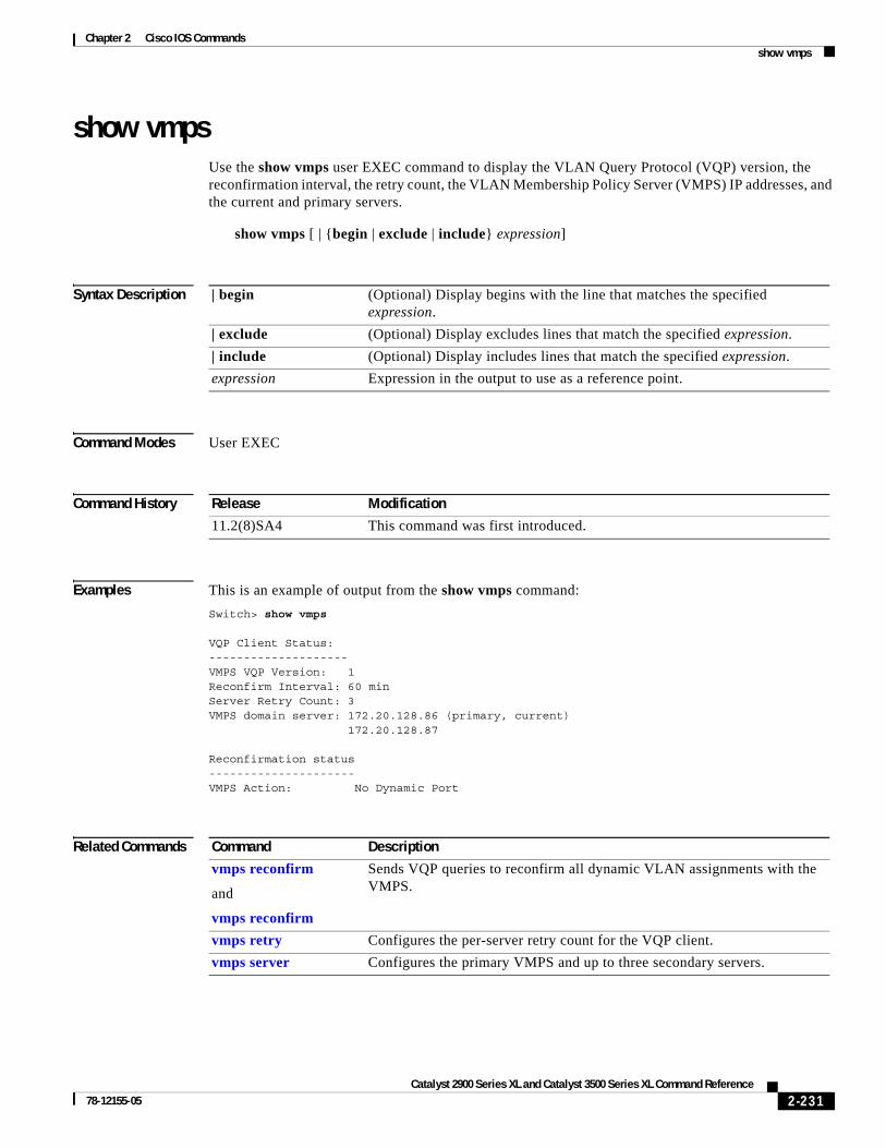
Chapter 2 Cisco IOS Commandsshow vmps
show vmpsUse the show vmps user EXEC command to display the VLAN Query Protocol (VQP) version, the reconfirmation interval, the retry count, the VLAN Membership Policy Server (VMPS) IP addresses, and the current and primary servers.
show vmps [ | {begin | exclude | include} expression]
Syntax Description
Command Modes User EXEC
Command History
Examples This is an example of output from the show vmps command:
Switch> show vmps
VQP Client Status:--------------------VMPS VQP Version: 1Reconfirm Interval: 60 minServer Retry Count: 3VMPS domain server: 172.20.128.86 (primary, current) 172.20.128.87 Reconfirmation status---------------------VMPS Action: No Dynamic Port
Related Commands
| begin (Optional) Display begins with the line that matches the specified expression.
| exclude (Optional) Display excludes lines that match the specified expression.
| include (Optional) Display includes lines that match the specified expression.
expression Expression in the output to use as a reference point.
Release Modification
11.2(8)SA4 This command was first introduced.
Command Description
vmps reconfirm
and
vmps reconfirm
Sends VQP queries to reconfirm all dynamic VLAN assignments with the VMPS.
vmps retry Configures the per-server retry count for the VQP client.
vmps server Configures the primary VMPS and up to three secondary servers.
2-231Catalyst 2900 Series XL and Catalyst 3500 Series XL Command Reference
78-12155-05

Chapter 2 Cisco IOS Commandsshow vmps statistics
show vmps statisticsUse the show vmps statistics privileged EXEC command to display the VLAN Query Protocol (VQP) client-side statistics and counters.
show vmps statistics [ | {begin | exclude | include} expression]
Syntax Description
Command Modes Privileged EXEC
Command History
Examples This is an example of output from the show vmps statistics command. Table 2-5 describes each field in the display.
Switch# show vmps statistics
VMPS Client Statistics----------------------VQP Queries: 0VQP Responses: 0VMPS Changes: 0VQP Shutdowns: 0VQP Denied: 0VQP Wrong Domain: 0VQP Wrong Version: 0VQP Insufficient Resource: 0
| begin (Optional) Display begins with the line that matches the specified expression.
| exclude (Optional) Display excludes lines that match the specified expression.
| include (Optional) Display includes lines that match the specified expression.
expression Expression in the output to use as a reference point.
Release Modification
11.2(8)SA4 This command was first introduced.
Table 2-5 Show VMPS Statistics Field Descriptions
Field Description
VQP Queries Number of queries sent by the client to the VLAN Membership Policy Server (VMPS).
VQP Responses Number of responses sent to the client from the VMPS.
VMPS Changes Number of times that the VMPS changed from one server to another.
VQP Shutdowns Number of times that the VMPS sent a response to shut down the port. The client disables the port and removes all dynamic addresses on this port from the address table. You must re-enable the port to restore connectivity.
2-232Catalyst 2900 Series XL and Catalyst 3500 Series XL Command Reference
78-12155-05
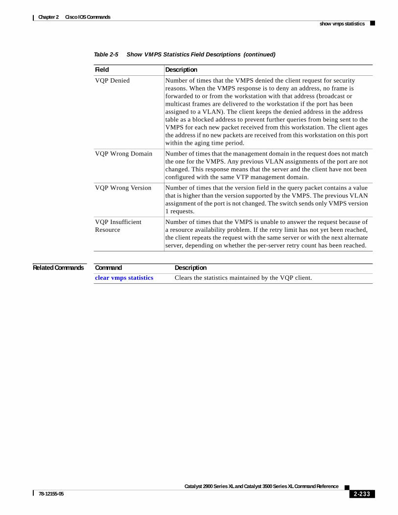
Chapter 2 Cisco IOS Commandsshow vmps statistics
Related Commands
VQP Denied Number of times that the VMPS denied the client request for security reasons. When the VMPS response is to deny an address, no frame is forwarded to or from the workstation with that address (broadcast or multicast frames are delivered to the workstation if the port has been assigned to a VLAN). The client keeps the denied address in the address table as a blocked address to prevent further queries from being sent to the VMPS for each new packet received from this workstation. The client ages the address if no new packets are received from this workstation on this port within the aging time period.
VQP Wrong Domain Number of times that the management domain in the request does not match the one for the VMPS. Any previous VLAN assignments of the port are not changed. This response means that the server and the client have not been configured with the same VTP management domain.
VQP Wrong Version Number of times that the version field in the query packet contains a value that is higher than the version supported by the VMPS. The previous VLAN assignment of the port is not changed. The switch sends only VMPS version 1 requests.
VQP Insufficient Resource
Number of times that the VMPS is unable to answer the request because of a resource availability problem. If the retry limit has not yet been reached, the client repeats the request with the same server or with the next alternate server, depending on whether the per-server retry count has been reached.
Table 2-5 Show VMPS Statistics Field Descriptions (continued)
Field Description
Command Description
clear vmps statistics Clears the statistics maintained by the VQP client.
2-233Catalyst 2900 Series XL and Catalyst 3500 Series XL Command Reference
78-12155-05

Chapter 2 Cisco IOS Commandsshow vtp
show vtpUse the show vtp user EXEC command to display general information about the VLAN Trunking Protocol (VTP) management domain, status, and counters.
show vtp {counters | status}[ | {begin | exclude | include} expression]
Syntax Description
Command Modes User EXEC
Command History
Examples This is an example of output from the show vtp counters command. Table 2-6, describes each field in the display.
Switch> show vtp counters
VTP statistics:Summary advertisements received : 38Subset advertisements received : 0Request advertisements received : 0Summary advertisements transmitted : 13Subset advertisements transmitted : 3Request advertisements transmitted : 0Number of config revision errors : 0Number of config digest errors : 0Number of V1 summary errors : 0
VTP pruning statistics:
Trunk Join Transmitted Join Received Summary advts received from non-pruning-capable device---------------- ---------------- ---------------- ---------------------------Fa0/9 827 824 0Fa0/10 827 823 0 Fa0/11 827 823 0
counters Display the VTP counters for the switch.
status Display general information about the VTP management domain.
| begin (Optional) Display begins with the line that matches the specified expression.
| exclude (Optional) Display excludes lines that match the specified expression.
| include (Optional) Display includes lines that match the specified expression.
expression Expression in the output to use as a reference point.
Release Modification
11.2(8)SA4 This command was first introduced.
2-234Catalyst 2900 Series XL and Catalyst 3500 Series XL Command Reference
78-12155-05

Chapter 2 Cisco IOS Commandsshow vtp
Table 2-6 Show VTP Counters Field Descriptions
Field Description
Summary Advts Received Number of summary advertisements received by this switch on its trunk ports. Summary advertisements contain the management domain name, the configuration revision number, the update timestamp and identity, the authentication checksum, and the number of subset advertisements to follow.
Subset Advts Received Number of subset advertisements received by this switch on its trunk ports. Subset advertisements contain all the information for one or more VLANs.
Request Advts Received Number of advertisement requests received by this switch on its trunk ports. Advertisement requests normally request information on all VLANs. They can also request information on a subset of VLANs.
Summary Advts Transmitted Number of summary advertisements sent by this switch on its trunk ports. Summary advertisements contain the management domain name, the configuration revision number, the update timestamp and identity, the authentication checksum, and the number of subset advertisements to follow.
Subset Advts Transmitted Number of subset advertisements sent by this switch on its trunk ports. Subset advertisements contain all the information for one or more VLANs.
Request Advts Transmitted Number of advertisement requests sent by this switch on its trunk ports. Advertisement requests normally request information on all VLANs. They can also request information on a subset of VLANs.
No. of Configuration Revision Errors
Number of revision errors.
Whenever you define a new VLAN, delete an existing one, suspend or resume an existing VLAN, or modify the parameters on an existing VLAN, the configuration revision number of the switch increments.
Revision errors increment whenever the switch receives an advertisement whose revision number matches the revision number of the switch, but the MD5 digest values do not match. This error means that the VTP password in the two switches is different or that the switches have different configurations.
These errors mean that the switch is filtering incoming advertisements, which causes the VTP database to become unsynchronized across the network.
2-235Catalyst 2900 Series XL and Catalyst 3500 Series XL Command Reference
78-12155-05

Chapter 2 Cisco IOS Commandsshow vtp
This is an example of output from the show vtp status command. Table 2-7, describes each field in the display.
Switch> show vtp status
VTP Version : 2Configuration Revision : 1Maximum VLANs supported locally : 68Number of existing VLANs : 7VTP Operating Mode : ServerVTP Domain Name : test1VTP Pruning Mode : DisabledVTP V2 Mode : DisabledVTP Traps Generation : DisabledMD5 digest : 0x3D 0x02 0xD4 0x3A 0xC4 0x46 0xA1 0x03Configuration last modified by 172.20.130.52 at 3-4-93 22:25:
No. of Configuration Digest Errors
Number of MD5 digest errors.
Digest errors increment whenever the MD5 digest in the summary packet and the MD5 digest of the received advertisement calculated by the switch do not match. This error usually means that the VTP password in the two switches is different. To solve this problem, make sure that the VTP password on all switches is the same.
These errors mean that the switch is filtering incoming advertisements, which causes the VTP database to become unsynchronized across the network.
No. of version 1 Summary Errors Number of version 1 errors.
Version 1 summary errors increment whenever a switch in VTP version 2 mode receives a VTP version 1 frame. These errors mean that at least one neighboring switch is either running VTP version 1 or VTP version 2 with version 2-mode disabled. To solve this problem, change the configuration of the switches in VTP version 2-mode to disabled.
Join Transmitted Number of VTP pruning messages transmitted on the trunk.
Join Received Number of VTP pruning messages received on the trunk.
Summary Advts Received from non-pruning-capable device
Number of VTP summary messages received on the trunk from devices that do not support pruning.
Table 2-6 Show VTP Counters Field Descriptions (continued)
Field Description
2-236Catalyst 2900 Series XL and Catalyst 3500 Series XL Command Reference
78-12155-05

Chapter 2 Cisco IOS Commandsshow vtp
Table 2-7 Show VTP Status Field Descriptions
Field Description
VTP Version Displays the VTP version operating on the switch. By default, Catalyst 2900 XL and Catalyst 3500 XL switches implement version 1 but can be set to version 2.
Configuration Revision Configuration revision number on this switch.
Maximum VLANs Supported Locally
Maximum number of VLANs supported locally.
Number of Existing VLANs Number of existing VLANs.
VTP Operating Mode Displays the VTP operating mode, which can be server, client, or transparent.
Server: a switch in VTP server mode is enabled for VTP and sends advertisements. You can configure VLANs on it. The switch guarantees that it can recover all the VLAN information in the VTP database from nonvolatile storage after reboot. By default, every switch is a VTP server.
Client: a switch in VTP client mode is enabled for VTP, can send advertisements, but does not have enough nonvolatile storage to store VLAN configurations. You cannot configure VLANs on it. When a VTP client starts up, it does not transmit VTP advertisements until it receives advertisements to initialize its VLAN database.
Transparent: a switch in VTP transparent mode is disabled for VTP, does not transmit advertisements or learn from advertisements sent by other devices, and cannot affect VLAN configurations on other devices in the network. The switch receives VTP advertisements and forwards them on all trunk ports except the one on which the advertisement was received. The configuration of multi-VLAN ports causes the switch to automatically enter transparent mode.
Note Catalyst 2912MF, 2924M, and Catalyst 3500 XL switches support up to 250 VLANs. All other Catalyst 2900 XL switches support up to 64 VLANs. If you define more than 250 or 64 or if the switch receives an advertisement that contains more than 250 or 64 VLANs, the switch automatically enters VTP transparent mode and operates with the VLAN configuration preceding the one that sent it into transparent mode.
VTP Domain Name Name that identifies the administrative domain for the switch.
VTP Pruning Mode Displays whether pruning is enabled or disabled. Enabling pruning on a VTP server enables pruning for the entire management domain. Pruning restricts flooded traffic to those trunk links that the traffic must use to access the appropriate network devices.
VTP version 2 Mode Displays if VTP version 2 mode is enabled. All VTP version 2 switches operate in version 1 mode by default. Each VTP switch automatically detects the capabilities of all the other VTP devices. A network of VTP devices should be configured to version 2 only if all VTP switches in the network can operate in version 2 mode.
2-237Catalyst 2900 Series XL and Catalyst 3500 Series XL Command Reference
78-12155-05

Chapter 2 Cisco IOS Commandsshow vtp
Related Commands
VTP Traps Generation Displays whether VTP traps are transmitted to a network management station.
MD5 Digest A 16-byte checksum of the VTP configuration.
Configuration Last Modified Displays the date and time of the last configuration modification. Displays the IP address of the switch that caused the configuration change to the database.
Table 2-7 Show VTP Status Field Descriptions (continued)
Field Description
Command Description
clear vtp counters Clears the VTP and pruning counters.
vtp Configures the VTP mode.
2-238Catalyst 2900 Series XL and Catalyst 3500 Series XL Command Reference
78-12155-05

Chapter 2 Cisco IOS Commandsshutdown
shutdown Use the shutdown interface configuration command to disable non-Long-Reach Ethernert (LRE) switch ports and to shut down the management VLAN. Use this command on an LRE switch port to disable the Ethernet ports on the connected customer premises equipment (CPE) device. Use the no form of this command to restart a disabled port or to activate the management VLAN.
shutdown
no shutdown
Syntax Description This command has no arguments or keywords.
Command Modes Interface configuration
Command History
Usage Guidelines The shutdown command for a non-LRE port causes it to stop forwarding. You can enable the port with the no shutdown command.
Entering the shutdown command for a switch LRE port disables the Ethernet ports on the CPE device connected to that switch LRE port.
The no shutdown command has no effect if the port is a static-access port assigned to a VLAN that has been deleted, suspended, or shut down. The port must first be a member of an active VLAN before it can be re-enabled.
Only one management VLAN interface can be active at a time. The remaining VLANs are shut down. In the show running-config command, the active management VLAN interface is the one with the shutdown command displayed.
Examples These examples show how to disable fixed port fa0/8 and how to re-enable it:
Switch(config)# interface fa0/8Switch(config-if)# shutdown
Switch(config-if)# no shutdown
You can verify the previous commands by entering the show interface user EXEC command.
Release Modification
11.2(8)SA This command was first introduced.
12.0(5)XP This command was extended to support the management VLAN interface.
12.0(5)WC4 This command was extended to support the CPE Ethernet ports.
2-239Catalyst 2900 Series XL and Catalyst 3500 Series XL Command Reference
78-12155-05

Chapter 2 Cisco IOS Commandsshutdown
Related Commands Command Description
management Shuts down the current management VLAN interface and enables the new management VLAN interface.
2-240Catalyst 2900 Series XL and Catalyst 3500 Series XL Command Reference
78-12155-05
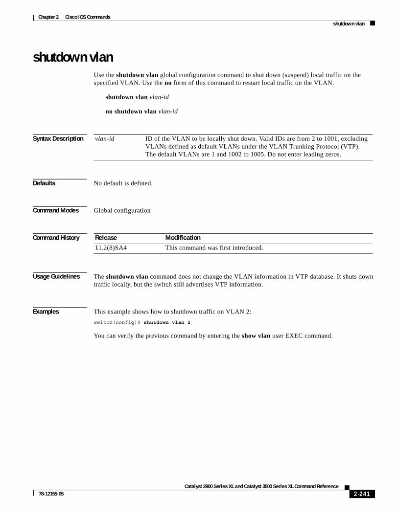
Chapter 2 Cisco IOS Commandsshutdown vlan
shutdown vlanUse the shutdown vlan global configuration command to shut down (suspend) local traffic on the specified VLAN. Use the no form of this command to restart local traffic on the VLAN.
shutdown vlan vlan-id
no shutdown vlan vlan-id
Syntax Description
Defaults No default is defined.
Command Modes Global configuration
Command History
Usage Guidelines The shutdown vlan command does not change the VLAN information in VTP database. It shuts down traffic locally, but the switch still advertises VTP information.
Examples This example shows how to shutdown traffic on VLAN 2:
Switch(config)# shutdown vlan 2
You can verify the previous command by entering the show vlan user EXEC command.
vlan-id ID of the VLAN to be locally shut down. Valid IDs are from 2 to 1001, excluding VLANs defined as default VLANs under the VLAN Trunking Protocol (VTP). The default VLANs are 1 and 1002 to 1005. Do not enter leading zeros.
Release Modification
11.2(8)SA4 This command was first introduced.
2-241Catalyst 2900 Series XL and Catalyst 3500 Series XL Command Reference
78-12155-05

Chapter 2 Cisco IOS Commandsshutdown vlan
Related Commands Command Description
abort Abandons the proposed VLAN database, exits VLAN database mode, and returns to privileged EXEC mode.
apply Implements the proposed VLAN database, increments the database configuration revision number, propagates it throughout the administrative domain, and remains in VLAN database mode.
exit Implements the proposed VLAN database, increments the database configuration number, propagates it throughout the administrative domain, and returns to privileged EXEC mode.
reset Abandons the proposed VLAN database and remains in VLAN database mode. Resets the proposed database to the currently implemented VLAN database on the switch.
vlan database Enters VLAN database mode from the command-line interface (CLI).
2-242Catalyst 2900 Series XL and Catalyst 3500 Series XL Command Reference
78-12155-05
Chapter 2 Cisco IOS Commandssnmp-server enable traps mac-notification
snmp-server enable traps mac-notificationUse the snmp-server enable traps mac-notification global configuration command to enable Simple Network Management Protocol (SNMP) traps used by the MAC address notification feature. Use the no form of this command to disable SNMP MAC address traps.
snmp-server enable traps mac-notification
no snmp-server enable traps mac-notification
Syntax Description This command has no arguments or keywords.
Defaults SNMP traps for the MAC notification feature are disabled.
Command Modes Global configuration
Command History
Usage Guidelines Traps are generated only when these conditions are met:
• The MAC address notification feature is enabled.
• The appropriate interface flag for address addition or deletion is enabled.
• Global MAC notification traps are enabled.
Examples This example shows how to enable SNMP traps used by the MAC address notification feature:
Switch(config)# snmp-server enable trap traps notification
You can verify the previous command by entering the show running-config privileged EXEC command.
Related Commands
Release Modification
12.0(5)WC(3) This command was first introduced.
Command Description
mac-address-table notification Enables the MAC address notification feature.
show running-config Displays the running configuration on the switch.
snmp-server host Specifies the host that receives SNMP traps.
snmp trap mac-notification Enables or disables MAC notification traps on a specific port.
2-243Catalyst 2900 Series XL and Catalyst 3500 Series XL Command Reference
78-12155-05

Chapter 2 Cisco IOS Commandssnmp-server enable traps vlan-membership
snmp-server enable traps vlan-membershipUse the snmp-server enable traps vlan-membership global configuration command to enable Simple Network Management Protocol (SNMP) notification for VLAN Membership Policy Server (VMPS) changes. Use the no form of this command to disable the VMPS trap notification.
snmp-server enable traps vlan-membership
no snmp-server enable traps vlan-membership
Syntax Description This command has no arguments or keywords.
Defaults SNMP traps for VMPS are disabled.
Command Modes Global configuration
Command History
Usage Guidelines Specify the host that receives the traps by using the snmp-server host global configuration command.
Examples This example shows how to enable VMPS to send trap notifications:
Switch(config)# snmp-server enable trap vlan-membership
You can verify the previous command by entering the show running-config privileged EXEC command.
Related Commands
Release Modification
11.2(8)SA4 This command was first introduced.
Command Description
show running-config Displays the running configuration on the switch.
snmp-server host Specifies the host that receives SNMP traps.
2-244Catalyst 2900 Series XL and Catalyst 3500 Series XL Command Reference
78-12155-05

Chapter 2 Cisco IOS Commandssnmp-server enable traps vtp
snmp-server enable traps vtpUse the snmp-server enable traps vtp global configuration command to enable Simple Network Management Protocol (SNMP) notification for VLAN Trunking Protocol (VTP) changes. Use the no form of this command to disable VTP trap notification.
snmp-server enable traps vtp
no snmp-server enable traps vtp
Syntax Description This command has no arguments or keywords.
Defaults SNMP traps for VTP are disabled.
Command Modes Global configuration
Command History
Usage Guidelines Specify the host that receives the traps by using the snmp-server host global configuration command.
Examples This example shows how to enable VTP to send trap notifications:
Switch(config)# snmp-server enable trap vtp
You can verify the previous command by entering the show vtp status user EXEC command or the show running-config privileged EXEC command.
Related Commands
Release Modification
11.2(8)SA4 This command was first introduced.
Command Description
show running-config Displays the running configuration on the switch.
show vtp status Displays general information about the VTP management domain and status.
snmp-server host Specifies the host that receives SNMP traps.
2-245Catalyst 2900 Series XL and Catalyst 3500 Series XL Command Reference
78-12155-05

Chapter 2 Cisco IOS Commandssnmp-server host
snmp-server hostUse the snmp-server host global configuration command to specify the host that receives Simple Network Management Protocol (SNMP) traps. Use the no form of this command to remove the specified host.
snmp-server host host-address community-string [c2900 | config | snmp | tty | udp-port port-number | vlan-membership | vtp]
no snmp-server host host-address community-string
Syntax Description
Defaults The SNMP trap host address and community string are not defined.
Traps are disabled.
Command Modes Global configuration
Command History
Usage Guidelines Use the snmp-server host global configuration command with the snmp-server enable traps global commands to generate traps.
host-address IP address or name of the SNMP trap host.
community-string Password-like community string sent with the trap operation.
c2900 (Optional) Send SNMP Catalyst 2900 XL or Catalyst 3500 XL switch traps.
config (Optional) Send SNMP configuration traps.
snmp (Optional) Send SNMP-type traps.
tty (Optional) Send Cisco enterprise-specific traps when a Transmission Control Protocol (TCP) connection closes.
udp-port port-number (Optional) UDP port of the host to use. The default is 162.
vlan-membership (Optional) Send SNMP VLAN Membership Policy Server (VMPS) traps
vtp (Optional) Send SNMP VLAN Trunking Protocol (VTP) traps.
Release Modification
11.2(8)SA4 This command was first introduced.
2-246Catalyst 2900 Series XL and Catalyst 3500 Series XL Command Reference
78-12155-05

Chapter 2 Cisco IOS Commandssnmp-server host
Examples This example shows how to configure an SNMP host to receive VTP traps:
Switch(config)# snmp-server host 172.20.128.178 traps vtp
You can verify the previous command by entering the show running-config privileged EXEC command.
Related Commands Command Description
snmp-server enable traps vlan-membership Enables SNMP notification for VMPS changes.
snmp-server enable traps vtp Enables SNMP notification for VTP changes.
2-247Catalyst 2900 Series XL and Catalyst 3500 Series XL Command Reference
78-12155-05
Chapter 2 Cisco IOS Commandssnmp trap mac-notification
snmp trap mac-notification Use the snmp trap mac-notification interface configuration command to enable or disable the MAC notification traps on a particular port. Use the no form of the command to return the port to default settings.
snmp trap mac-notification [added | removed]
no snmp trap mac-notification [added | removed]
Syntax Description
Defaults The SNMP address-addition and address-removal traps are disabled.
Command Modes Interface configuration
Command History
Usage Guidelines Even though the notification trap is enabled for a particular port, the trap is actually generated only when the global MAC trap flag is also enabled. To enable the global trap flag, use the snmp-server enable traps mac-notification global configuration command.
Examples This example shows how to enable an address-addition trap on a port:
Switch(config-if)# snmp trap mac-notification added
This example shows how to enable an address-removal trap on a port:
Switch(config-if)# snmp trap mac-notification removed
You can verify the previous commands by entering the show running-config privileged EXEC command.
Related Commands
added (Optional) Enable MAC notification traps whenever a MAC address is added on this port.
removed (Optional) Enable MAC notification traps whenever a MAC address is removed from this port.
Release Modification
12.0(5)WC3 This command was first introduced.
Command Description
mac-address-table notification Enables the MAC notification feature on a switch.
show mac-address-table notification Displays MAC-notification parameters.
2-248Catalyst 2900 Series XL and Catalyst 3500 Series XL Command Reference
78-12155-05

Chapter 2 Cisco IOS Commandsspanning-tree
spanning-treeUse the spanning-tree global configuration command to enable Spanning Tree Protocol (STP) on a VLAN. Use the no form of the command to disable STP on a VLAN.
spanning-tree [vlan stp-list]
no spanning-tree [vlan stp-list]
Syntax Description
Defaults STP is enabled.
Command Modes Global configuration
Command History
Usage Guidelines Disabling STP causes the VLAN or a list of VLANs to stop participating in STP. Ports that are administratively down remain down. Received bridge protocol data units (BPDUs) are forwarded like other multicast frames. The VLAN does not detect and prevent loops when STP is disabled.
You can disable STP on a VLAN that is not active and verify the change by using the privileged EXEC show running-config or the show spanning-tree vlan stp-list privileged EXEC commands. The setting takes effect when the VLAN is activated.
If the variable stp-list is omitted, the command applies to the STP instance associated with VLAN 1.
You can enable STP on a VLAN that has no ports assigned to it.
Examples This example shows how to disable STP on VLAN 5:
Switch(config)# no spanning-tree vlan 5
You can verify the previous command by entering the show spanning-tree user EXEC command. In this instance, VLAN 5 does not appear in the list.
vlan stp-list (Optional) List of spanning-tree instances. Each spanning-tree instance is associated with a VLAN ID. Valid IDs are from 1 to 1005. Enter each VLAN ID separated by a space. Do not enter leading zeros. Ranges are not supported.
Release Modification
11.2(8)SA3 This command was first introduced.
2-249Catalyst 2900 Series XL and Catalyst 3500 Series XL Command Reference
78-12155-05

Chapter 2 Cisco IOS Commandsspanning-tree
Related Commands Command Description
show spanning-tree Displays spanning-tree information for the specified spanning-tree instances.
spanning-tree forward-time Specifies the forwarding-time for the specified spanning-tree instances.
spanning-tree max-age Changes the interval between messages the spanning tree receives from the root switch.
spanning-tree port-priority Configures a port priority, which is used when two switches tie for position as the root switch.
spanning-tree protocol Specifies the STP version to be used for specified spanning-tree instances.
2-250Catalyst 2900 Series XL and Catalyst 3500 Series XL Command Reference
78-12155-05

Chapter 2 Cisco IOS Commandsspanning-tree cost
spanning-tree costUse the spanning-tree cost interface configuration command to set the path cost for Spanning Tree Protocol (STP) calculations. In the event of a loop, spanning tree considers the path cost when selecting an interface to place into the forwarding state. Use the no form of this command to return to the default value.
spanning-tree [vlan stp-list] cost cost
no spanning-tree [vlan stp-list] cost
Syntax Description
Defaults The default path cost is computed from the interface bandwidth setting. These are the IEEE default path cost values:
• 10 Mbps – 100
• 100 Mbps – 19
• 155 Mbps – 14
• 1 Gbps – 4
• 10 Gbps – 2
• Speeds greater than 10 Gbps – 1
Command Modes Interface configuration
Command History
Usage Guidelines If the variable stp-list is omitted, the command applies to the spanning-tree instance associated with VLAN 1.
You can set a cost for a port or on a VLAN that does not exist. The setting takes effect when the VLAN exists.
Examples This example shows how to set a path cost value of 250 for VLAN 1:
Switch(config-if)# spanning-tree vlan 1 cost 250
You can verify the previous command by entering the show spanning-tree user EXEC command.
vlan stp-list (Optional) List of spanning-tree instances. Each spanning-tree instance is associated with a VLAN ID. Valid IDs are from 1 to 1005. Enter each VLAN ID separated by a space. Do not enter leading zeros. Ranges are not supported.
cost Path cost can range from 1 to 65535, with higher values indicating higher costs. This range applies whether or not the IEEE STP has been specified.
Release Modification
11.2(8)SA3 This command was first introduced.
2-251Catalyst 2900 Series XL and Catalyst 3500 Series XL Command Reference
78-12155-05
Chapter 2 Cisco IOS Commandsspanning-tree cost
Related Commands Command Description
show spanning-tree Displays spanning-tree information for the specified spanning-tree instances.
spanning-tree portfast Enables the Port Fast feature on a port in all its associated VLANs.
spanning-tree priority Configures the switch priority for the specified spanning-tree instance.
2-252Catalyst 2900 Series XL and Catalyst 3500 Series XL Command Reference
78-12155-05

Chapter 2 Cisco IOS Commandsspanning-tree forward-time
spanning-tree forward-timeUse the spanning-tree forward-time global configuration command to set the forwarding-time for the specified spanning-tree instances. The forwarding time determines how long each of the listening and learning states last before the port begins forwarding. Use the no form of this command to return to the default value.
spanning-tree [vlan stp-list] forward-time seconds
no spanning-tree [vlan stp-list] forward-time
Syntax Description
Defaults The default forwarding-time for IEEE Spanning Tree Protocol (STP) is 15 seconds. The default for IBM STP is 4 seconds.
Command Modes Global configuration
Command History
Usage Guidelines If the variable stp-list is omitted, the command applies to the STP instance associated with VLAN 1.
You can set the forwarding-time on a VLAN that has no ports assigned to it. The setting takes effect when you assign ports to it.
Examples This example shows how to set the spanning-tree forwarding time to 18 seconds for VLAN 20:
Switch(config)# spanning-tree vlan 20 forward-time 18
You can verify the previous command by entering the show spanning-tree user EXEC command.
vlan stp-list (Optional) List of spanning-tree instances. Each spanning-tree instance is associated with a VLAN ID. Valid IDs are from 1 to 1005. Enter each VLAN ID separated by a space. Do not enter leading zeros. Ranges are not supported.
seconds Forward-delay interval from 4 to 200 seconds.
Release Modification
11.2(8)SA3 This command was first introduced.
2-253Catalyst 2900 Series XL and Catalyst 3500 Series XL Command Reference
78-12155-05

Chapter 2 Cisco IOS Commandsspanning-tree forward-time
Related Commands Command Description
show spanning-tree Displays spanning-tree information for the specified spanning-tree instances.
spanning-tree max-age Changes the interval between messages the spanning tree receives from the root switch.
spanning-tree port-priority Configures a port priority, which is used when two switches tie for position as the root switch.
spanning-tree protocol Specifies the STP version to be used for specified spanning-tree instances.
2-254Catalyst 2900 Series XL and Catalyst 3500 Series XL Command Reference
78-12155-05

Chapter 2 Cisco IOS Commandsspanning-tree hello-time
spanning-tree hello-timeUse the spanning-tree hello-time global configuration command to specify the interval between hello bridge protocol data units (BPDUs). Use the no form of this command to return to the default interval.
spanning-tree [vlan stp-list] hello-time seconds
no spanning-tree [vlan stp-list] hello-time
Syntax Description
Defaults The default hello time for IEEE Spanning Tree Protocol (STP) and IBM STP is 2 seconds.
Command Modes Global configuration
Command History
Usage Guidelines If the variable stp-list is omitted, the command applies to the STP instance associated with VLAN 1.
You can set the hello time on a VLAN that has no ports assigned to it. The setting takes effect when you assign ports to it.
Examples This example shows how to set the spanning-tree hello-delay time to 3 seconds for VLAN 20:
Switch(config)# spanning-tree vlan 20 hello-time 3
You can verify the previous command by entering the show spanning-tree user EXEC command.
Related Commands
vlan stp-list (Optional) List of spanning-tree instances. Each spanning-tree instance is associated with a VLAN ID. Valid IDs are from 1 to 1005. Enter each VLAN ID separated by a space. Do not enter leading zeros. Ranges are not supported.
seconds Interval from 1 to 10 seconds.
Release Modification
11.2(8)SA3 This command was first introduced.
Command Description
show spanning-tree Displays spanning-tree information for the specified spanning-tree instances.
spanning-tree Enables STP on a VLAN.
spanning-tree port-priority Configures a port priority, which is used when two switches tie for position as the root switch.
spanning-tree protocol Specifies the STP version to be used for specified spanning-tree instances.
2-255Catalyst 2900 Series XL and Catalyst 3500 Series XL Command Reference
78-12155-05

Chapter 2 Cisco IOS Commandsspanning-tree max-age
spanning-tree max-ageUse the spanning-tree max-age global configuration command to change the interval between messages the spanning tree receives from the root switch. If a switch does not receive a bridge protocol data unit (BPDU) message from the root switch within this interval, it recomputes the Spanning Tree Protocol (STP) topology. Use the no form of this command to return to the default interval.
spanning-tree [vlan stp-list] max-age seconds
no spanning-tree [vlan stp-list] max-age
Syntax Description
Defaults The default max-age for IEEE STP is 20 seconds. The default for IBM STP is 10 seconds.
Command Modes Global configuration
Command History
Usage Guidelines The max-age setting must be greater than the hello-time setting.
If the variable stp-list is omitted, the command applies to the STP instance associated with VLAN 1.
You can set the max-age on a VLAN that has no ports assigned to it. The setting takes effect when you assign ports to the VLAN.
Examples This example shows how to set spanning-tree max-age to 30 seconds for VLAN 20:
Switch(config)# spanning-tree vlan 20 max-age 30
This example shows how to reset the max-age parameter to the default value for spanning-tree instances 100 through 102:
Switch(config)# no spanning-tree vlan 100 101 102 max-age
You can verify the previous commands by entering the show spanning-tree user EXEC command.
vlan stp-list (Optional) List of spanning-tree instances. Each spanning-tree instance is associated with a VLAN ID. Valid IDs are from 1 to 1005. Enter each VLAN ID separated by a space. Do not enter leading zeros. Ranges are not supported.
seconds Interval the switch waits between receiving BPDUs from the root switch. Enter a number from 6 to 200.
Release Modification
11.2(8)SA3 This command was first introduced.
2-256Catalyst 2900 Series XL and Catalyst 3500 Series XL Command Reference
78-12155-05

Chapter 2 Cisco IOS Commandsspanning-tree max-age
Related Commands Command Description
show spanning-tree Displays spanning-tree information for the specified spanning-tree instances.
spanning-tree forward-time Specifies the forwarding-time for the specified spanning-tree instances.
spanning-tree hello-time Specifies the interval between hello bridge protocol data units (BPDUs).
spanning-tree port-priority Configures a port priority, which is used when two switches tie for position as the root switch.
spanning-tree protocol Specifies the STP version to be used for specified spanning-tree instances.
2-257Catalyst 2900 Series XL and Catalyst 3500 Series XL Command Reference
78-12155-05

Chapter 2 Cisco IOS Commandsspanning-tree portfast
spanning-tree portfastUse the spanning-tree portfast interface configuration command to enable the Port Fast feature on a port in all its associated VLANs. When the Port Fast feature is enabled, the port changes directly from a blocking state to a forwarding state without making the intermediate Spanning Tree Protocol (STP) status changes. Use the no form of this command to return the port to default operation.
spanning-tree portfast
no spanning-tree portfast
Syntax Description This command has no keywords or arguments.
Defaults The Port Fast feature is disabled; however, it is automatically enabled on dynamic-access ports.
Command Modes Interface configuration
Command History
Usage Guidelines This feature is not supported on the Asynchronous Transfer Mode (ATM) modules.
Use this feature only on ports that connect to end stations.
This feature affects all VLANs on the port.
A port with the Port Fast feature enabled is moved directly to the spanning-tree forwarding state.
Examples This example shows how to enable the Port Fast feature on fixed port 2.
Switch(config-if)# interface FastEthernet 0/2Switch(config-if)# spanning-tree portfast
You can verify the previous commands by entering the show running-config in privileged EXEC mode.
Related Commands
Release Modification
11.2(8)SA3 This command was first introduced.
Command Description
show spanning-tree Displays spanning-tree information for the specified spanning-tree instances.
spanning-tree port-priority Configures a port priority, which is used when two switches tie for position as the root switch.
2-258Catalyst 2900 Series XL and Catalyst 3500 Series XL Command Reference
78-12155-05

Chapter 2 Cisco IOS Commandsspanning-tree portfast bpduguard
spanning-tree portfast bpduguardUse the spanning-tree portfast bpduguard global configuration command to globally enable the Bridge Protocol Data Unit (BPDU) guard feature on the switch. It shuts down Port Fast-configured interfaces that receive BPDUs rather than putting them into the spanning-tree blocking state. Use the no form of this command to return to the default setting.
spanning-tree portfast bpduguard
no spanning-tree portfast bpduguard
Syntax Description This command has no arguments or keywords.
Defaults The BPDU guard feature is disabled on the switch.
Command Modes Global configuration
Command History
Usage Guidelines In a valid configuration, Port Fast-enabled interfaces do not receive BPDUs. When the BPDU guard feature is enabled on the switch, STP shuts down Port Fast-enabled interfaces that receive BPDUs rather than putting the interfaces into the blocking state.
Note When enabled on the switch, STP applies the BPDU guard feature to all Port Fast-enabled interfaces.
Caution The BPDU guard feature works on Port Fast-enabled interfaces. Configure Port Fast only on interfaces that connect to end stations; otherwise, an accidental topology loop could cause a data packet loop and disrupt switch and network operation.
Release Modification
12.0(5)WC5 This command was first introduced.
2-259Catalyst 2900 Series XL and Catalyst 3500 Series XL Command Reference
78-12155-05
Chapter 2 Cisco IOS Commandsspanning-tree portfast bpduguard
Examples This example shows how to enable BPDU guard feature:
Switch(config)# spanning-tree portfast bpduguard
You can verify your setting by entering the show running-config privileged EXEC command.
Related Commands Command Description
show spanning-tree Displays spanning-tree information for the specified spanning-tree instances.
spanning-tree portfast Enables the Port Fast feature on an interface in all its associated VLANs.
2-260Catalyst 2900 Series XL and Catalyst 3500 Series XL Command Reference
78-12155-05

Chapter 2 Cisco IOS Commandsspanning-tree port-priority
spanning-tree port-priorityUse the spanning-tree port-priority interface configuration command to configure a port priority that is used when two switches tie for position as the root switch. Use the no form of this command to return to the default value.
spanning-tree [vlan stp-list] port-priority port-priority
no spanning-tree [vlan stp-list] port-priority
Syntax Description
Defaults The default port-priority for IEEE STP and IBM STP is 128.
Command Modes Interface configuration
Command History
Usage Guidelines If the variable stp-list is omitted, the command applies to the STP instance associated with VLAN 1.
You can set the port priority on a VLAN that has no ports assigned to it. The setting takes effect when you assign ports to the VLAN.
Examples This example shows how to increase the likelihood that the spanning-tree instance 20 is chosen as the root switch on port fa0/2:
Switch(config)# interface fa0/2Switch(config-if)# spanning-tree vlan 20 port-priority 0
You can verify the previous commands by entering the show spanning-tree user EXEC command.
Related Commands
vlan stp-list (Optional) List of spanning-tree instances. Each spanning-tree instance is associated with a VLAN ID. Valid IDs are from 1 to 1005. Enter each VLAN ID separated by a space. Do not enter leading zeros. Ranges are not supported.
port-priority Number from 0 to 255. The lower the number, the higher the priority.
Release Modification
11.2(8)SA3 This command was first introduced.
Command Description
show spanning-tree Displays spanning-tree information for the specified spanning-tree instances.
spanning-tree protocol Specifies the STP version to be used for specified spanning-tree instances.
2-261Catalyst 2900 Series XL and Catalyst 3500 Series XL Command Reference
78-12155-05

Chapter 2 Cisco IOS Commandsspanning-tree priority
spanning-tree priorityUse the spanning-tree priority global configuration command to configure the switch priority for the specified spanning-tree instance. This changes the likelihood that the switch is selected as the root switch. Use the no form of this command to revert to the default value.
spanning-tree [vlan stp-list] priority bridge-priority
no spanning-tree [vlan stp-list] priority
Syntax Description
Defaults The default bridge priority for IEEE STP and IBM STP is 32768.
Command Modes Global configuration
Command History
Usage Guidelines If the variable stp-list is omitted, the command applies to the STP instance associated with VLAN 1.
You can configure the switch priority on a VLAN that has no ports assigned to it. The setting takes effect when you assign ports to the VLAN.
Examples This example shows how to set the spanning-tree priority to 125 for a list of VLANs:
Switch(config)# spanning-tree vlan 20 100 101 102 priority 125
You can verify the previous command by entering the show spanning-tree user EXEC command.
vlan stp-list (Optional) List of spanning-tree instances. Each spanning-tree instance is associated with a VLAN ID. Valid IDs are from 1 to 1005. Enter each VLAN ID separated by a space. Do not enter leading zeros. Ranges are not supported.
bridge-priority A number from 0 to 65535. The lower the number, the more likely the switch will be chosen as root.
Release Modification
11.2(8)SA3 This command was first introduced.
2-262Catalyst 2900 Series XL and Catalyst 3500 Series XL Command Reference
78-12155-05

Chapter 2 Cisco IOS Commandsspanning-tree priority
Related Commands Command Description
show spanning-tree Displays spanning-tree information for the specified spanning-tree instances.
spanning-tree forward-time Specifies the forwarding-time for the specified spanning-tree instances.
spanning-tree hello-time Specifies the interval between hello bridge protocol data units (BPDUs).
spanning-tree max-age Changes the interval between messages the spanning tree receives from the root switch.
spanning-tree protocol Specifies the STP version to be used for specified spanning-tree instances.
2-263Catalyst 2900 Series XL and Catalyst 3500 Series XL Command Reference
78-12155-05
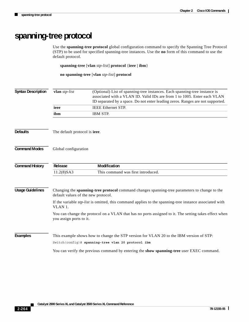
Chapter 2 Cisco IOS Commandsspanning-tree protocol
spanning-tree protocolUse the spanning-tree protocol global configuration command to specify the Spanning Tree Protocol (STP) to be used for specified spanning-tree instances. Use the no form of this command to use the default protocol.
spanning-tree [vlan stp-list] protocol {ieee | ibm}
no spanning-tree [vlan stp-list] protocol
Syntax Description
Defaults The default protocol is ieee.
Command Modes Global configuration
Command History
Usage Guidelines Changing the spanning-tree protocol command changes spanning-tree parameters to change to the default values of the new protocol.
If the variable stp-list is omitted, this command applies to the spanning-tree instance associated with VLAN 1.
You can change the protocol on a VLAN that has no ports assigned to it. The setting takes effect when you assign ports to it.
Examples This example shows how to change the STP version for VLAN 20 to the IBM version of STP:
Switch(config)# spanning-tree vlan 20 protocol ibm
You can verify the previous command by entering the show spanning-tree user EXEC command.
vlan stp-list (Optional) List of spanning-tree instances. Each spanning-tree instance is associated with a VLAN ID. Valid IDs are from 1 to 1005. Enter each VLAN ID separated by a space. Do not enter leading zeros. Ranges are not supported.
ieee IEEE Ethernet STP.
ibm IBM STP.
Release Modification
11.2(8)SA3 This command was first introduced.
2-264Catalyst 2900 Series XL and Catalyst 3500 Series XL Command Reference
78-12155-05

Chapter 2 Cisco IOS Commandsspanning-tree protocol
Related Commands Command Description
show spanning-tree Displays spanning-tree information for the specified spanning-tree instances.
spanning-tree Enables STP on a VLAN.
spanning-tree forward-time Specifies the forwarding-time for the specified spanning-tree instances.
spanning-tree max-age Changes the interval between messages that the spanning tree receives from the root switch.
spanning-tree port-priority Configures a port priority, that is used when two switches tie for position as the root switch.
2-265Catalyst 2900 Series XL and Catalyst 3500 Series XL Command Reference
78-12155-05

Chapter 2 Cisco IOS Commandsspanning-tree rootguard
spanning-tree rootguardUse the spanning-tree rootguard interface configuration command to enable the root guard feature for all the VLANs associated with the selected port. Root guard restricts which port is allowed to be the Spanning Tree Protocol (STP) root port or the path-to-the root for the switch. The root port provides the best path from the switch to the root switch. Use the no form of this command to disable this feature.
spanning-tree rootguard
no spanning-tree rootguard
Syntax Description This command has no keywords or arguments.
Defaults The root guard feature is disabled.
Command Modes Interface configuration
Command History
Usage Guidelines When the root guard feature is enabled, if spanning-tree calculations cause a port to be selected as the root port, the port transitions to the root-inconsistent (blocked) state to prevent the customer’s switch from becoming the root switch or being in the path to the root.
When the no spanning-tree rootguard command is entered, the root guard feature is disabled for all VLANs on the selected port. If this port is in the root-inconsistent (blocked) state, the port automatically transitions to the listening state.
Do not enable the root guard on ports that will be used by the UplinkFast feature. With UplinkFast, the backup ports (in the blocked state) replace the root port in the case of a failure. However, if root guard is also enabled, all the backup ports used by the UplinkFast feature are placed in the root-inconsistent state (blocked) and prevented from reaching the forwarding state.
Examples This example shows how to enable the root guard feature on all the VLANs associated with interface fa0/3:
Switch(config)# interface fa0/3Switch(config-if)# spanning-tree rootguard
You can verify the previous commands by entering the show running-config privileged EXEC command.
Release Modification
12.0(5)XU This command was first introduced.
2-266Catalyst 2900 Series XL and Catalyst 3500 Series XL Command Reference
78-12155-05
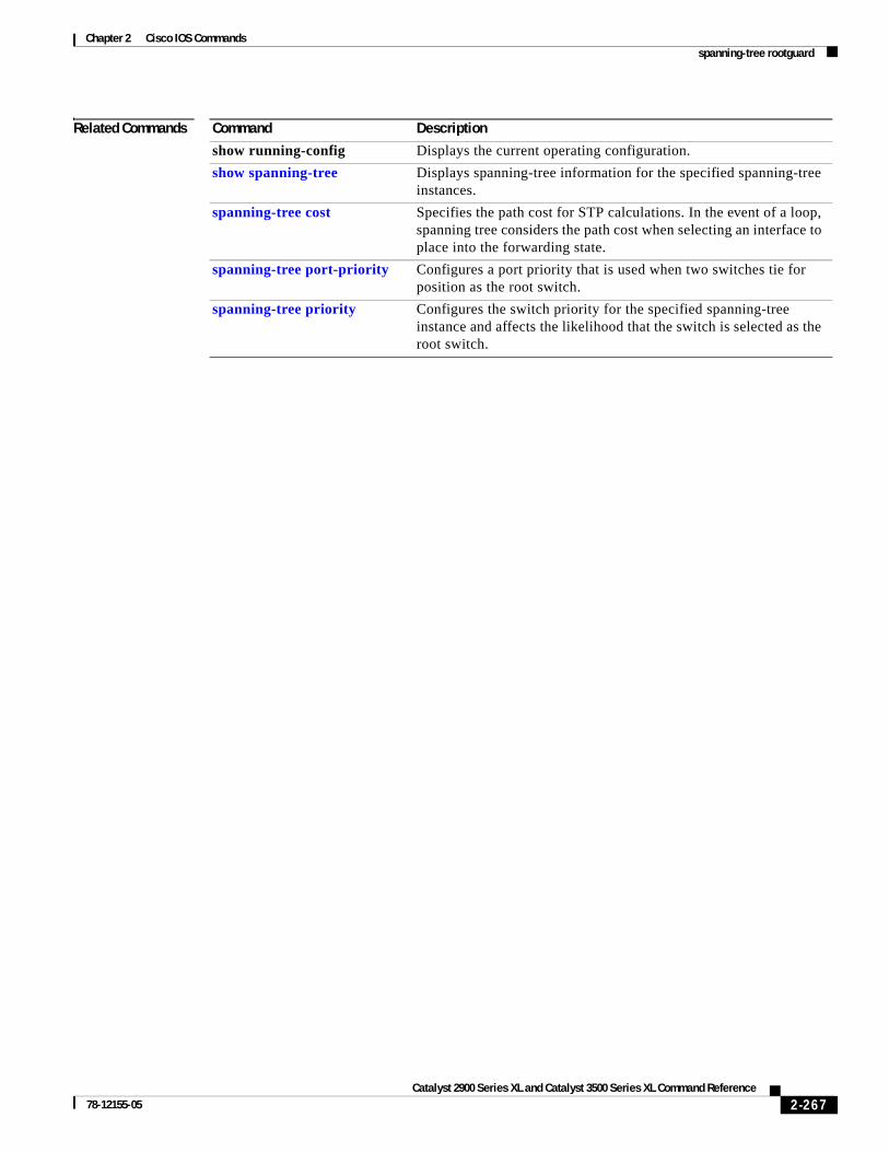
Chapter 2 Cisco IOS Commandsspanning-tree rootguard
Related Commands Command Description
show running-config Displays the current operating configuration.
show spanning-tree Displays spanning-tree information for the specified spanning-tree instances.
spanning-tree cost Specifies the path cost for STP calculations. In the event of a loop, spanning tree considers the path cost when selecting an interface to place into the forwarding state.
spanning-tree port-priority Configures a port priority that is used when two switches tie for position as the root switch.
spanning-tree priority Configures the switch priority for the specified spanning-tree instance and affects the likelihood that the switch is selected as the root switch.
2-267Catalyst 2900 Series XL and Catalyst 3500 Series XL Command Reference
78-12155-05
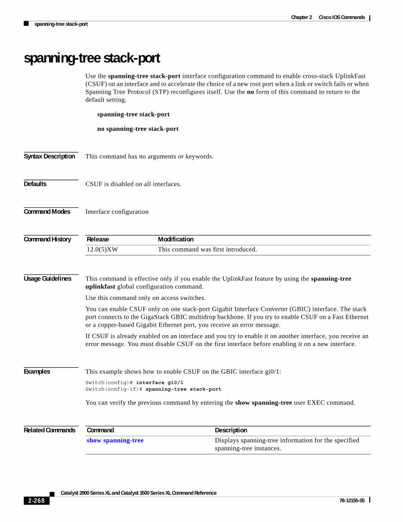
Chapter 2 Cisco IOS Commandsspanning-tree stack-port
spanning-tree stack-portUse the spanning-tree stack-port interface configuration command to enable cross-stack UplinkFast (CSUF) on an interface and to accelerate the choice of a new root port when a link or switch fails or when Spanning Tree Protocol (STP) reconfigures itself. Use the no form of this command to return to the default setting.
spanning-tree stack-port
no spanning-tree stack-port
Syntax Description This command has no arguments or keywords.
Defaults CSUF is disabled on all interfaces.
Command Modes Interface configuration
Command History
Usage Guidelines This command is effective only if you enable the UplinkFast feature by using the spanning-tree uplinkfast global configuration command.
Use this command only on access switches.
You can enable CSUF only on one stack-port Gigabit Interface Converter (GBIC) interface. The stack port connects to the GigaStack GBIC multidrop backbone. If you try to enable CSUF on a Fast Ethernet or a copper-based Gigabit Ethernet port, you receive an error message.
If CSUF is already enabled on an interface and you try to enable it on another interface, you receive an error message. You must disable CSUF on the first interface before enabling it on a new interface.
Examples This example shows how to enable CSUF on the GBIC interface gi0/1:
Switch(config)# interface gi0/1Switch(config-if)# spanning-tree stack-port
You can verify the previous command by entering the show spanning-tree user EXEC command.
Related Commands
Release Modification
12.0(5)XW This command was first introduced.
Command Description
show spanning-tree Displays spanning-tree information for the specified spanning-tree instances.
2-268Catalyst 2900 Series XL and Catalyst 3500 Series XL Command Reference
78-12155-05

Chapter 2 Cisco IOS Commandsspanning-tree uplinkfast
spanning-tree uplinkfastUse the spanning-tree uplinkfast global configuration command to accelerate the choice of a new root port when a link or switch fails or when Spanning Tree Protocol (STP) reconfigures itself. Use the no form of this command to return to the default value.
spanning-tree uplinkfast [max-update-rate pkts-per-second]
no spanning-tree uplinkfast [max-update-rate pkts-per-second]
Syntax Description
Defaults UplinkFast is disabled.
Command Modes Global configuration
Command History
Usage Guidelines When you enable UplinkFast, it is enabled for the entire switch and cannot be enabled for individual VLANs.
When you enable UplinkFast, the bridge priority of all VLANs is set to 49152, and the path cost of all ports and VLAN trunks is increased by 3000. This change reduces the chance that the switch will become the root switch.
When you disable UplinkFast, the bridge priorities of all VLANs and path costs are set to their default values.
Do not enable the root guard on ports that will be used by the UplinkFast feature. With UplinkFast, the backup ports (in the blocked state) replace the root port in the case of a failure. However, if root guard is also enabled, all the backup ports used by the UplinkFast feature are placed in the root-inconsistent state (blocked) and prevented from reaching the forwarding state.
Examples This command shows how to enable UplinkFast:
Switch(config)# spanning-tree uplinkfast
You can verify the previous command by entering the show spanning-tree user EXEC command.
Related Commands
max-update-rate pkts-per-second The number of packets per second at which stations address update packets are sent. The range is 0 to 1000.
Release Modification
11.2(8)SA6 This command was first introduced.
Command Description
show spanning-tree Displays spanning-tree information for the specified spanning-tree instances.
2-269Catalyst 2900 Series XL and Catalyst 3500 Series XL Command Reference
78-12155-05

Chapter 2 Cisco IOS Commandsspeed
speedUse the speed interface configuration command to specify the speed of a Fast Ethernet port. Use the no form of this command to return the port to its default value.
speed {10 | 100 | auto}
no speed
Syntax Description
Defaults For Fast Ethernet ports, the default is auto.
For Gigabit Ethernet ports, the speed is 1000 Mbps and is not configurable.
For Asynchronous Transfer Mode (ATM) ports, the speed is 155 Mbps and is not configurable.
Command Modes Interface configuration
Command History
Usage Guidelines Certain ports can be configured to be either 10 or 100 Mbps. Applicability of this command is hardware-dependent.
If the speed is set to auto, the switch negotiates with the device at the other end of the link for the speed setting and then forces the speed setting to the negotiated value. The duplex setting remains as configured on each end of the link, which could result in a duplex setting mismatch.
For LRE CPE devices connected to the switch LRE ports, autonegotiation for speed is supported. You can change the speed setting on the Cisco 575 LRE CPE devices, but you cannot on the Cisco 585 LRE CPE devices.
If both the speed and duplex are set to specific values, autonegotiation is disabled.
Note For guidelines on setting the switch speed and duplex parameters, refer to the Catalyst 2900 Series XL and Catalyst 3500 Series XL Software Configuration Guide.
10 Port runs at 10 Mbps.
100 Port runs at 100 Mbps.
auto Port automatically detects whether it should run at 10 or 100 Mbps on Fast Ethernet ports.
Release Modification
11.2(8)SA This command was first introduced.
12.0(5)WC1 This command was extended to support Long-Reach Ethernet (LRE) customer premises equipment (CPE) devices.
12.0(5)WC4 This command was extended to support the Cisco 585 LRE CPE.
2-270Catalyst 2900 Series XL and Catalyst 3500 Series XL Command Reference
78-12155-05

Chapter 2 Cisco IOS Commandsspeed
Examples This example shows how to set port 1 on module 2 to 100 Mbps:
Switch(config)# interface fastethernet2/1Switch(config-if)# speed 100
You can verify the previous commands by entering the show running-config in privileged EXEC mode.
Related Commands Command Description
duplex Specifies the duplex mode of operation for Fast Ethernet and Gigabit Ethernet ports.
2-271Catalyst 2900 Series XL and Catalyst 3500 Series XL Command Reference
78-12155-05

Chapter 2 Cisco IOS Commandsswitchport access
switchport accessUse the switchport access interface configuration command to configure a port as a static-access or dynamic-access port. If the mode is set to access, the port operates as a member of the configured VLAN. If set to dynamic, the port starts discovery of VLAN assignment based on the incoming packets it receives. Use the no form of this command to reset the access mode to the default VLAN for the switch.
switchport access vlan {vlan-id | dynamic}
no switchport access vlan {vlan-id | dynamic}
Syntax Description
Defaults All ports are in static-access mode in VLAN 1.
A dynamic-access port is initially a member of no VLAN and receives its assignment based on the packets it receives.
Command Modes Interface configuration
Command History
Usage Guidelines The port must be in access mode before the switchport access vlan vlan-id or switchport access vlan dynamic command can take effect. For more information, see the “switchport mode” section on page 2-274.
An access port can be assigned to only one VLAN.
When the no switchport access vlan form is used, the access mode is reset to static access on VLAN 1.
These restrictions apply to dynamic-access ports:
• The software implements the VLAN Query Protocol (VQP) client, which can query a VMPS such as a Catalyst 5000 series switch. Catalyst 2900 XL and Catalyst 3500 XL switches are not VMPS servers. The VMPS server must be configured before a port is configured as dynamic.
• Use dynamic-access ports only to connect end stations. Connecting them to switches or routers (that use bridging protocols) can cause a loss of connectivity.
vlan vlan-id ID of the VLAN. Valid IDs are from 1 to 1001. Do not enter leading zeros.
dynamic Port is assigned to a VLAN based on the source MAC address of a host (or hosts) connected to that port. The switch sends every new source MAC address received to the VLAN Membership Policy Server (VMPS) to obtain the VLAN name to which the dynamic-access port should be assigned. If the port already has a VLAN assigned and the source has already been approved by the VMPS, the switch forwards the packet to the VLAN.
Release Modification
11.2(8)SA3 This command was first introduced.
11.2(8)SA4 The dynamic keyword was added.
2-272Catalyst 2900 Series XL and Catalyst 3500 Series XL Command Reference
78-12155-05

Chapter 2 Cisco IOS Commandsswitchport access
• Configure the network so that STP does not put the dynamic-access port into an STP blocking state. The Port Fast feature is automatically enabled on dynamic-access ports.
• Dynamic-access ports can only be in one VLAN and do not use VLAN tagging.
• Dynamic-access ports cannot be configured as:
– The source or destination port in a static address entry.
– A network port (dynamic-access ports can be assigned to a VLAN in which one of the other ports is a network port).
– A port group (dynamic-access ports cannot be grouped with any other port including other dynamic ports).
– A secure port.
– A port with a secure address.
– A monitor port.
Examples This example shows how to assign a port already in access mode to VLAN 2 (instead of the default VLAN 1):
Switch(config-if)# switchport access vlan 2
This example shows how to assign a port already in access mode to dynamic:
Switch(config-if)# switchport access vlan dynamic
This example shows how to reconfigure a dynamic-access port to a static-access port:
Switch(config-if)# no switchport access vlan dynamic
You can verify the previous commands by entering the show interface interface-id switchport command in privileged EXEC mode and examining information in the Administrative Mode and Operational Mode rows.
Related Commands Command Description
switchport mode Configures the VLAN membership mode of a port.
switchport multi Configures a list of VLANs to which the port is associated.
2-273Catalyst 2900 Series XL and Catalyst 3500 Series XL Command Reference
78-12155-05

Chapter 2 Cisco IOS Commandsswitchport mode
switchport mode Use the switchport mode interface configuration command to configure the VLAN membership mode of a port. Use the no form of this command to reset the mode to the appropriate default for the device.
switchport mode {access | multi | trunk}
no switchport mode {access | multi | trunk}
Syntax Description
Defaults All ports are static-access ports in VLAN 1.
Command Modes Interface configuration
Command History
Usage Guidelines The access, multi, or trunk keywords take effect only when you change the port to the corresponding mode by using the switchport mode command. The static-access, multi-VLAN, and trunk configurations are saved, but only one configuration is active at a time.
The no switchport mode form resets the mode to static access.
Only these combinations of port modes can appear on a single switch:
• Multi-VLAN and access ports
• Trunk and access ports
Trunk and multi-VLAN ports cannot coexist on the same switch. If you want to change a multi-VLAN or trunk port into another mode, you must first change it to an access port and then reassign it to the new mode.
access Set the port to access mode (either static-access or dynamic-access depending on the setting of the switchport access vlan command). The port operates as a nontrunking, single VLAN interface that transmits and receives nonencapsulated frames. An access port can be assigned to only one VLAN.
multi Set the port to multi-VLAN port mode. The port operates as a nontrunking VLAN interface that transmits and receives nonencapsulated frames. A multi-VLAN port can be assigned to one or more VLANs.
trunk Set the port to a trunking VLAN Layer 2 interface. The port transmits and receives encapsulated (tagged) frames that identify the VLAN of origination. A trunk is a point-to-point link between two switches or between a switch and a router.
Release Modification
11.2(8)SA3 This command was first introduced.
11.2(8)SA4 The trunk keyword was added.
2-274Catalyst 2900 Series XL and Catalyst 3500 Series XL Command Reference
78-12155-05
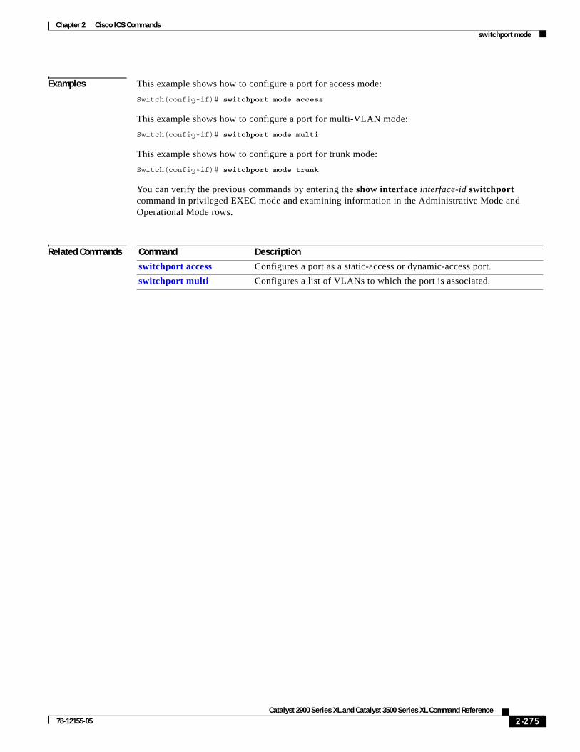
Chapter 2 Cisco IOS Commandsswitchport mode
Examples This example shows how to configure a port for access mode:
Switch(config-if)# switchport mode access
This example shows how to configure a port for multi-VLAN mode:
Switch(config-if)# switchport mode multi
This example shows how to configure a port for trunk mode:
Switch(config-if)# switchport mode trunk
You can verify the previous commands by entering the show interface interface-id switchport command in privileged EXEC mode and examining information in the Administrative Mode and Operational Mode rows.
Related Commands Command Description
switchport access Configures a port as a static-access or dynamic-access port.
switchport multi Configures a list of VLANs to which the port is associated.
2-275Catalyst 2900 Series XL and Catalyst 3500 Series XL Command Reference
78-12155-05

Chapter 2 Cisco IOS Commandsswitchport multi
switchport multiUse the switchport multi interface configuration command to configure a list of VLANs to which the port is associated. If the mode is set to multi, the port operates as a member of all VLANs in the list. Use the no form of this command to reconfigure the port as an access port.
switchport multi vlan {add vlan-list | remove vlan-list}
no switchport multi vlan
Syntax Description
Defaults The default for VLAN membership of a multi-VLAN port is VLAN 1.
Command Modes Interface configuration
Command History
Usage Guidelines The switchport mode multi command must be entered before the switchport multi vlan vlan-list command can take effect.
In the variable vlan-list, separate nonconsecutive VLAN IDs with a comma; use a hyphen to designate a range of IDs.
A multi-VLAN port cannot be a secure port or a monitor port.
A multi-VLAN port cannot coexist with a trunk port on the same switch.
Caution To avoid loss of connectivity, do not connect multi-VLAN ports to hubs or switches. Connect multi-VLAN ports to routers or servers.
vlan Indicate the VLAN to which the port is associated.
add vlan-list List of VLAN IDs to add. Valid IDs are from 1 to 1001. Separate nonconsecutive VLAN IDs with a comma and no spaces; use a hyphen to designate a range of IDs. Do not enter leading zeros.
remove vlan-list List of VLAN IDs to remove. Valid IDs are from 1 to 1001. Separate nonconsecutive VLAN IDs with a comma and no spaces; use a hyphen to designate a range of IDs. Do not enter leading zeros.
Release Modification
11.2(8)SA3 This command was first introduced.
2-276Catalyst 2900 Series XL and Catalyst 3500 Series XL Command Reference
78-12155-05
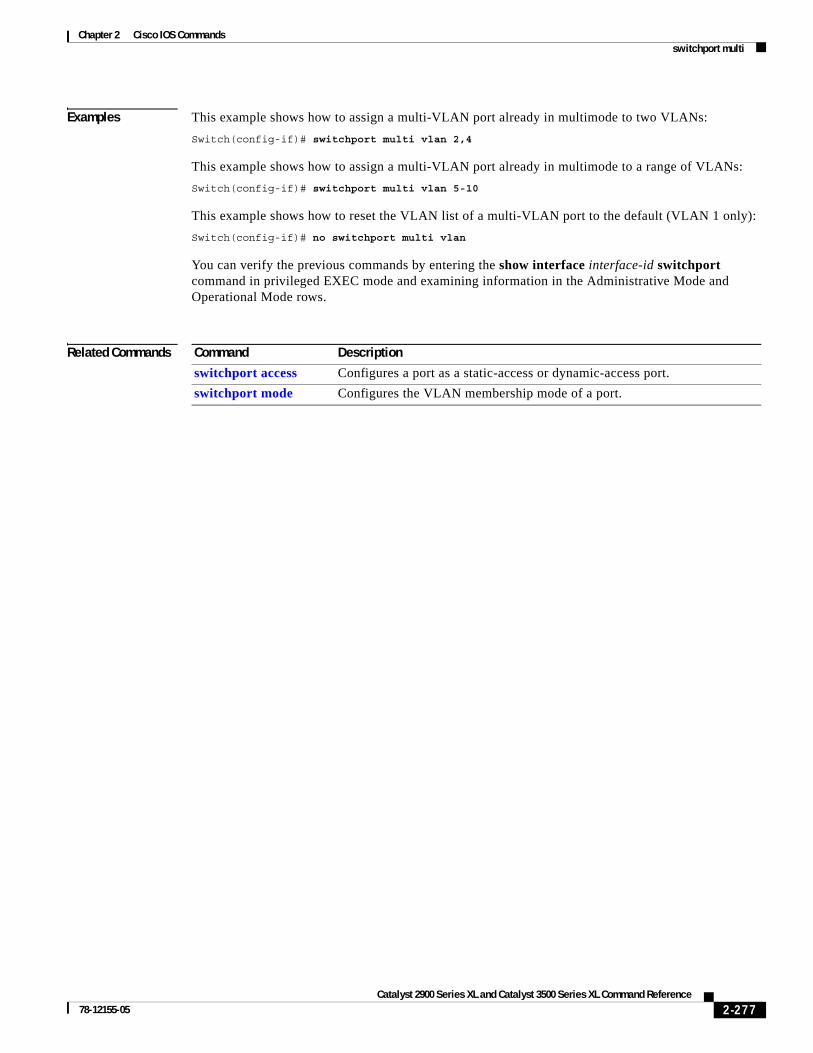
Chapter 2 Cisco IOS Commandsswitchport multi
Examples This example shows how to assign a multi-VLAN port already in multimode to two VLANs:
Switch(config-if)# switchport multi vlan 2,4
This example shows how to assign a multi-VLAN port already in multimode to a range of VLANs:
Switch(config-if)# switchport multi vlan 5-10
This example shows how to reset the VLAN list of a multi-VLAN port to the default (VLAN 1 only):
Switch(config-if)# no switchport multi vlan
You can verify the previous commands by entering the show interface interface-id switchport command in privileged EXEC mode and examining information in the Administrative Mode and Operational Mode rows.
Related Commands Command Description
switchport access Configures a port as a static-access or dynamic-access port.
switchport mode Configures the VLAN membership mode of a port.
2-277Catalyst 2900 Series XL and Catalyst 3500 Series XL Command Reference
78-12155-05

Chapter 2 Cisco IOS Commandsswitchport priority
switchport priorityUse the switchport priority interface configuration command to set a port priority for the incoming untagged frames or the priority of frames received by the appliance connected to the specified port. Use the no form of this command to return the setting to its default.
switchport priority {default default-priority-id | extend {cos value | none | trust} | override}
no switchport priority {default default-priority-id | extend | override}
Syntax Description
Defaults The port priority is not set, and the default value for untagged frames received on the port is zero.
The appliance connected to the port is not instructed (none) what to do with the priority.
Command Modes Interface configuration
Command History
Usage Guidelines The default port priority applies if the incoming frame is an untagged frame received from a VLAN trunk or static-access port. This port priority does not apply to the ISL or IEEE 802.1Q VLAN tagged frames. If the incoming frame is an 802.1Q VLAN tagged frame, the 802.1P User Priority bits is used.
The cos keyword only applies to the 3524-PWR and 3548 XL switches.
default-priority-id The priority number for untagged traffic. The priority is a number from 0 to 7. Seven is the highest priority.
extend Set the 802.1P priority of the switch.
• cos value—Override the 802.1P priority of devices connected to the switch. The cos value is a number from 0 to 7. Seven is the highest priority. The cos keyword only applies to the 3524-PWR and the 3548 XL switches.
• none—The switch is not instructed what to do with the priority.
• trust—Specify that the switch should trust (honor) the received 802.1P priority from devices connected to it.
override Override the priority of tagged frames with the default value.
Release Modification
12.0(5)XP This command was first introduced.
12.0(5)XU The extend keyword and its options were added.
2-278Catalyst 2900 Series XL and Catalyst 3500 Series XL Command Reference
78-12155-05

Chapter 2 Cisco IOS Commandsswitchport priority
Examples This example shows how to set a default priority on port 3.
Switch(config)# interface fa0/3Switch(config-if)# switchport priority default 7
All untagged frames received from this port will have the same priority value. You can verify the previous commands by entering the show interface interface-id switchport privileged EXEC command.
This example shows how to configure the appliance connected to the specified port to honor the received 802.1P priority:
Switch(config-if)# switchport priority extend trust
You can verify the previous command by entering the show interface interface-id switchport privileged EXEC command.
Related Commands Command Description
power inline Determines how inline power is applied to the specified port on the Catalyst 3524-PWR XL switch.
show interface Displays the administrative and operational status of a switching (nonrouting) port.
switchport access Configures a port as a static-access or dynamic-access port.
switchport mode Configures the VLAN membership mode of a port.
switchport voice vlan Configures the voice VLAN on the port.
2-279Catalyst 2900 Series XL and Catalyst 3500 Series XL Command Reference
78-12155-05

Chapter 2 Cisco IOS Commandsswitchport trunk allowed vlan
switchport trunk allowed vlanUse the switchport trunk allowed vlan interface configuration command to control which VLANs can receive and transmit traffic on the trunk. Use the no form of this command to reset the allowed list to the default value.
switchport trunk allowed vlan {add vlan-list | all | except vlan-list | remove vlan-list}
no switchport trunk allowed vlan
Syntax Description
Defaults All VLANs are included in the allowed list.
Command Modes Interface configuration
Command History
Usage Guidelines When you use the no switchport trunk allowed vlan form, the allowed list resets to the default list, which includes all VLANs.
In the variable vlan-list, separate nonconsecutive VLAN IDs with a comma; use a hyphen to designate a range of IDs. You cannot remove VLANs 1 or 1002 to 1005 from the list.
A trunk port cannot be a secure port or a monitor port. However, a static-access port can monitor a VLAN on a trunk port. The VLAN monitored is the one associated with the static-access port.
If a trunk port is identified as a network port, the trunk port becomes the network port for all the VLANs associated with the port.
add vlan-list List of VLAN IDs to add. Valid IDs are from 1 to 1001. Separate nonconsecutive VLAN IDs with a comma and no spaces; use a hyphen to designate a range of IDs. Do not enter leading zeros.
all Add all VLAN IDs to the list.
except vlan-list List of exception VLAN IDs. VLANs are added except the ones specified. Valid IDs are from 1 to 1001. Separate nonconsecutive VLAN IDs with a comma and no spaces; use a hyphen to designate a range of IDs. Do not enter leading zeros.
remove vlan-list List of VLAN IDs to remove. Valid IDs are from 1 to 1001. Separate nonconsecutive VLAN IDs with a comma and no spaces; use a hyphen to designate a range of IDs. Do not enter leading zeros.
Release Modification
11.2(8)SA4 This command was first introduced.
2-280Catalyst 2900 Series XL and Catalyst 3500 Series XL Command Reference
78-12155-05

Chapter 2 Cisco IOS Commandsswitchport trunk allowed vlan
Examples This example shows how to add VLANs 1, 2, 5, and 6 to the allowed list:
Switch(config-if)# switchport trunk allowed vlan add 1,2,5,6
You can verify the previous command by entering the show interface interface-id switchport privileged EXEC command.
Related Commands Command Description
switchport mode Configures the VLAN membership mode of a port.
switchport trunk encapsulation Specifies the encapsulation format on the trunk port.
switchport trunk native Specifies the native VLAN for untagged traffic when in 802.1Q trunking mode.
2-281Catalyst 2900 Series XL and Catalyst 3500 Series XL Command Reference
78-12155-05

Chapter 2 Cisco IOS Commandsswitchport trunk encapsulation
switchport trunk encapsulationUse the switchport trunk encapsulation interface configuration command to set the encapsulation format on the trunk port. Use the no form of this command to reset the format to the default.
switchport trunk encapsulation {isl | dot1q}
no switchport trunk encapsulation
Syntax Description
Defaults The default encapsulation format is ISL.
Command Modes Interface configuration
Command History
Usage Guidelines You cannot configure one end of the trunk as an 802.1Q trunk and the other end as an ISL or nontrunk port. However, you can configure one port as an ISL trunk and another port on the same switch as a 802.1Q trunk.
This command is only applicable on switch platforms and port hardware that support both formats.
Examples This example shows how to configure the encapsulation format to 802.1Q:
Switch(config-if)# switchport trunk encapsulation dot1q
You can verify the previous command by entering the show interface interface-id switchport privileged EXEC command.
isl Set the encapsulation format to Inter-Switch Link (ISL). The switch encapsulates all received and transmitted packets with an ISL header. The switch filters native frames received from an ISL trunk port.
dot1q Set the tagging format to IEEE 802.1Q. With this format, the switch supports simultaneous tagged and untagged traffic on a port.
Release Modification
11.2(8)SA4 This command was first introduced.
11.2(8)SA5 The dot1q keyword was added.
2-282Catalyst 2900 Series XL and Catalyst 3500 Series XL Command Reference
78-12155-05

Chapter 2 Cisco IOS Commandsswitchport trunk encapsulation
Related Commands Command Description
switchport mode Configures the VLAN membership mode of a port.
switchport trunk allowed vlan Controls which VLANs can receive and transmit traffic on the trunk.
switchport trunk native Specifies the native VLAN for untagged traffic when in 802.1Q trunking mode.
2-283Catalyst 2900 Series XL and Catalyst 3500 Series XL Command Reference
78-12155-05

Chapter 2 Cisco IOS Commandsswitchport trunk native
switchport trunk nativeUse the switchport trunk native interface configuration command to set the native VLAN for untagged traffic when in 802.1Q trunking mode. Use the no form of this command to reset the native VLAN to the default.
switchport trunk native vlan vlan-id
no switchport trunk native
Syntax Description
Defaults VLAN 1 is the default native VLAN ID on the port.
Command Modes Interface configuration
Command History
Usage Guidelines All untagged traffic received on the 802.1Q trunk port is forwarded with the native VLAN configured for the port.
If a packet has a VLAN ID that is the same as the sending port native VLAN ID, the packet is transmitted untagged; otherwise, the switch transmits the packet with a tag.
Examples This example shows how to configure VLAN 3 as the default port to send all untagged traffic:
Switch(config-if)# switchport trunk native vlan 3
You can verify the previous command by entering the show interface interface-id switchport privileged EXEC command.
Related Commands
vlan vlan-id ID of the VLAN that is sending and receiving untagged traffic on the trunk port. Valid IDs are from 1 to 1001. Do not enter leading zeros.
Release Modification
11.2(8)SA4 This command was first introduced.
Command Description
switchport mode Configures the VLAN membership mode of a port.
switchport trunk allowed vlan Controls which VLANs can receive and transmit traffic on the trunk.
switchport trunk encapsulation Specifies the encapsulation format on the trunk port.
2-284Catalyst 2900 Series XL and Catalyst 3500 Series XL Command Reference
78-12155-05

Chapter 2 Cisco IOS Commandsswitchport trunk pruning
switchport trunk pruningUse the switchport trunk pruning interface configuration command to configure the VLAN pruning-eligible list for ports in trunking mode. Use the no form of this command to return the pruning list to the default setting.
switchport trunk pruning vlan {add vlan-list | all | except vlan-list | remove vlan-list}
no switchport trunk pruning
Syntax Description
Defaults VLANs 2 through 1001 are pruning eligible.
Command Modes Interface configuration
Command History
Usage Guidelines The pruning-eligible list applies only to trunk ports.
Each trunk port has its own eligibility list.
If you do not want a VLAN to be pruned, remove it from the pruning-eligible list. VLANs that are pruning-ineligible receive flooded traffic.
Examples This example shows how to remove VLANs 3 and 10 to 15 from the pruning-eligible list:
Switch(config-if)# switchport trunk pruning vlan remove 3,10-15
You can verify the previous command by entering the show interface interface-id switchport privileged EXEC command.
add vlan-list List of VLAN IDs to add. Valid IDs are from 2 to 1001. Separate nonconsecutive VLAN IDs with a comma and no spaces; use a hyphen to designate a range of IDs. Do not enter leading zeros.
all Add all VLAN IDs to the list.
except vlan-list List of exception VLAN IDs (VLANs are added except the specified ones). Valid IDs are from 2 to 1001. Separate nonconsecutive VLAN IDs with a comma and no spaces; use a hyphen to designate a range of IDs. Do not enter leading zeros.
remove vlan-list List of VLAN IDs to remove. Valid IDs are from 2 to 1001. Separate nonconsecutive VLAN IDs with a comma and no spaces; use a hyphen to designate a range of IDs. Do not enter leading zeros.
no Set the pruning list to the default.
Release Modification
12.0(5)XU This command was first introduced.
2-285Catalyst 2900 Series XL and Catalyst 3500 Series XL Command Reference
78-12155-05
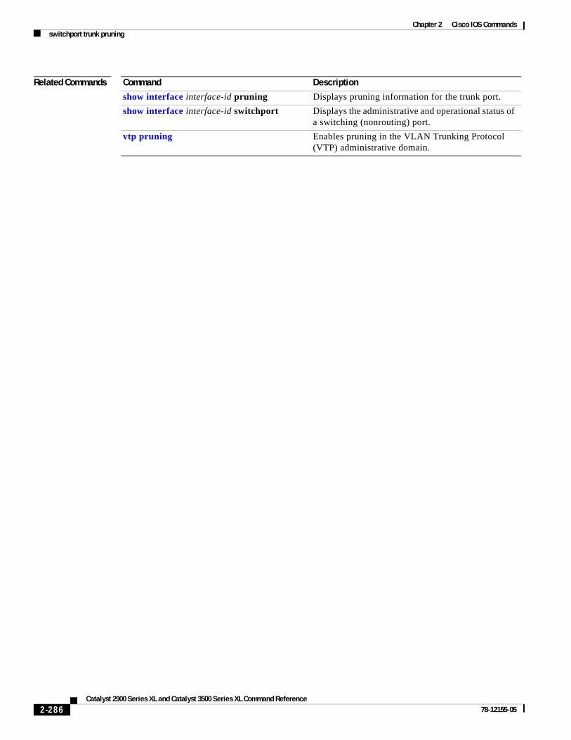
Chapter 2 Cisco IOS Commandsswitchport trunk pruning
Related Commands Command Description
show interface interface-id pruning Displays pruning information for the trunk port.
show interface interface-id switchport Displays the administrative and operational status of a switching (nonrouting) port.
vtp pruning Enables pruning in the VLAN Trunking Protocol (VTP) administrative domain.
2-286Catalyst 2900 Series XL and Catalyst 3500 Series XL Command Reference
78-12155-05
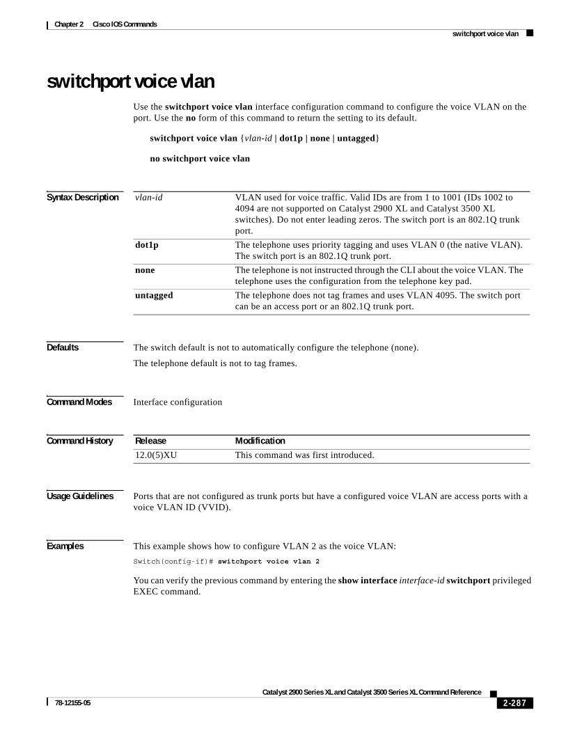
Chapter 2 Cisco IOS Commandsswitchport voice vlan
switchport voice vlanUse the switchport voice vlan interface configuration command to configure the voice VLAN on the port. Use the no form of this command to return the setting to its default.
switchport voice vlan {vlan-id | dot1p | none | untagged}
no switchport voice vlan
Syntax Description
Defaults The switch default is not to automatically configure the telephone (none).
The telephone default is not to tag frames.
Command Modes Interface configuration
Command History
Usage Guidelines Ports that are not configured as trunk ports but have a configured voice VLAN are access ports with a voice VLAN ID (VVID).
Examples This example shows how to configure VLAN 2 as the voice VLAN:
Switch(config-if)# switchport voice vlan 2
You can verify the previous command by entering the show interface interface-id switchport privileged EXEC command.
vlan-id VLAN used for voice traffic. Valid IDs are from 1 to 1001 (IDs 1002 to 4094 are not supported on Catalyst 2900 XL and Catalyst 3500 XL switches). Do not enter leading zeros. The switch port is an 802.1Q trunk port.
dot1p The telephone uses priority tagging and uses VLAN 0 (the native VLAN). The switch port is an 802.1Q trunk port.
none The telephone is not instructed through the CLI about the voice VLAN. The telephone uses the configuration from the telephone key pad.
untagged The telephone does not tag frames and uses VLAN 4095. The switch port can be an access port or an 802.1Q trunk port.
Release Modification
12.0(5)XU This command was first introduced.
2-287Catalyst 2900 Series XL and Catalyst 3500 Series XL Command Reference
78-12155-05
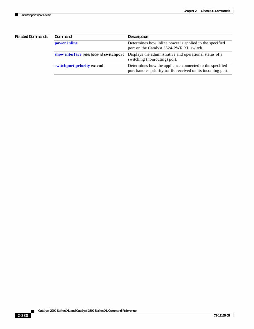
Chapter 2 Cisco IOS Commandsswitchport voice vlan
Related Commands Command Description
power inline Determines how inline power is applied to the specified port on the Catalyst 3524-PWR XL switch.
show interface interface-id switchport Displays the administrative and operational status of a switching (nonrouting) port.
switchport priority extend Determines how the appliance connected to the specified port handles priority traffic received on its incoming port.
2-288Catalyst 2900 Series XL and Catalyst 3500 Series XL Command Reference
78-12155-05

Chapter 2 Cisco IOS Commandstacacs-server attempts
tacacs-server attemptsUse the tacacs-server attempts global configuration command to control the number of login attempts that can be made on a line set up for Terminal Access Controller Access Control System (TACACS), Extended TACACS, or TACACS+ verification. Use the no form of this command to disable this feature and to restore the default.
tacacs-server attempts count
no tacacs-server attempts
Syntax Description
Defaults The default number of login attempts is 3.
Command Modes Global configuration
Command History
Examples This example shows how to change the login attempt to just one:
Switch(config)# tacacs-server attempts 1
You can verify the previous command by entering the show running-config privileged EXEC command.
Related Commands
count Integer that sets the number of attempts. The range is from 1 to 1000.
Release Modification
11.2(8)SA6 This command was first introduced.
Command Description
login tacacs Configures the switch to use TACACS user authentication.
show tacacs Displays various TACACS+ server statistics.
tacacs-server directed request Sends only a username to a specified server when a direct request is issued in association with TACACS, Extended TACACS, and TACACS+.
tacacs-server host Specifies a TACACS, Extended TACACS, or TACACS+ host.
tacacs-server key Specifies the authentication encryption key used for all TACACS+ communications between the access server and the TACACS+ daemon.
tacacs-server last-resort Causes the network access server to request the privileged password as verification for TACACS or Extended TACACS or to allow successful login without further user input.
udld Specifies the interval that the server waits for a TACACS, Extended TACACS, or TACACS+ server to reply.
2-289Catalyst 2900 Series XL and Catalyst 3500 Series XL Command Reference
78-12155-05

Chapter 2 Cisco IOS Commandstacacs-server dns-alias-lookup
tacacs-server dns-alias-lookupUse the tacacs-server dns-alias-lookup global configuration command to enable IP Domain Name System alias lookup for Terminal Access Controller Access Control System Plus (TACACS+). Use the no form of this command to disable this feature.
tacacs-server dns-alias-lookup
no tacacs-server dns-alias-lookup
Syntax Description This command has no keywords or arguments.
Defaults The DNS alias lookup is disabled.
Command Modes Global configuration
Command History
Examples This example shows how to enable the IP DNS alias lookup:
Switch(config)# tacacs-server dns-alias-lookup
You can verify the previous command by entering the show running-config privileged EXEC command.
Related Commands
Release Modification
11.2(8)SA6 This command was first introduced.
Command Description
ip domain-name Defines a default domain name that is used to complete unqualified host names (names without a dotted-decimal domain name).
ip name-server Specifies the address of one or more name servers to use for name and address resolution.
2-290Catalyst 2900 Series XL and Catalyst 3500 Series XL Command Reference
78-12155-05

Chapter 2 Cisco IOS Commandsudld
udldUse the udld interface configuration command to enable UniDirectional Link Detection (UDLD) on a port to assist with the detection of spanning-tree loops on logical one-way connections. Use the no form of this command to return the port setting to the global setting.
udld {enable | disable}
no udld {enable | disable}
Syntax Description
Defaults UDLD follows the setting of the udld enable global configuration command and is disabled on all ports.
Command Modes Interface configuration
Command History
Usage Guidelines UDLD is supported on fiber- and copper-based Ethernet ports.
UDLD is not supported on ATM interfaces.
A UDLD-capable port cannot detect a unidirectional link if it is connected to a UDLD-incapable port of another switch.
Setting UDLD on an interface overrides the global UDLD configuration for that specific interface.
Examples This example shows how to enable UDLD on port 2:
Switch(config)# interface fastethernet 0/2Switch(config-if)# udld enable
You can verify the previous command by entering the show running-config or the show udld interface command in privileged EXEC mode.
Related Commands
enable Enable UDLD on the specified port.
disable Disable UDLD on the specified port.
Release Modification
12.0(5)XU This command was first introduced.
Command Description
show running-config Displays the running configuration on the switch.
udld enable Enables UDLD on all ports on the switch.
udld reset Resets any interface that has been shut down by UDLD.
2-291Catalyst 2900 Series XL and Catalyst 3500 Series XL Command Reference
78-12155-05
Chapter 2 Cisco IOS Commandsudld enable
udld enableUse the udld enable global configuration command to enable UniDirectional Link Detection (UDLD) on all ports on the switch to assist with the detection of spanning-tree loops on logical one-way connections. Use the no form of this command to return the switch setting to its default value.
udld enable
no udld enable
Syntax Description This command has no keywords or arguments.
Defaults UDLD is disabled on the switch.
Command Modes Global configuration mode
Command History
Usage Guidelines UDLD is supported on fiber- and copper-based Ethernet ports.
UDLD is not supported on Asynchronous Transfer Mode (ATM) interfaces.
A UDLD-capable port cannot detect a unidirectional link if it is connected to a UDLD-incapable port of another switch.
The udld enable global configuration command setting is overwritten by each specific port UDLD configuration.
Examples This example shows how to enable UDLD on the switch:
Switch(config)# udld enable
You can verify the previous command by entering the show running-config in privileged EXEC mode.
Related Commands
Release Modification
12.0(5)XU This command was first introduced.
Command Description
show running-config Displays the running configuration on the switch.
udld Enables UDLD on a port.
udld reset Resets any interface that has been shut down by UDLD.
2-292Catalyst 2900 Series XL and Catalyst 3500 Series XL Command Reference
78-12155-05

Chapter 2 Cisco IOS Commandsudld reset
udld resetUse the udld reset privileged EXEC command to reset all interfaces that have been shut down by UniDirectional Link Detection (UDLD).
udld reset
Syntax Description This command has no keywords or arguments.
Command Modes Privileged EXEC mode
Command History
Examples This example shows how to reset all interfaces that have been shut down by UDLD:
Switch# udld reset1 ports shutdown by UDLD were reset.
You can verify the previous command by entering the show udld user EXEC command.
Related Commands
Release Modification
12.0(5)XU This command was first introduced.
Command Description
show running-config Displays the running configuration on the switch.
udld Enables UDLD on a port.
udld enable Enables UDLD on all ports on the switch.
2-293Catalyst 2900 Series XL and Catalyst 3500 Series XL Command Reference
78-12155-05
Chapter 2 Cisco IOS Commandsupgrade binary
upgrade binaryUse the upgrade binary controller configuration command to configure the behavior of a Long-Reach Ethernet (LRE) controller upgrade.
upgrade binary LRE binary [ remote lre-interface ]
no upgrade binary LRE binary [ remote lre-interface ]
Syntax Description
Command Modes Controller configuration mode
Command History
Usage Guidelines This configuration command is normally not needed. The default behavior for an upgrade is for the system to select the binary version. Use this command when you need to specify a particular upgrade binary file for a local controller in an LRE switch or for a remote CPE device connected to the controller. If you use the command without parameters, the LRE binary is applied to the local controller when it is upgraded. If you specify the remote keyword and interface, the LRE binary is applied to the CPE device at the end of the remote LRE link at upgrade time.
Upgrade configurations entered from the controller configuration mode take precedence over upgrade configurations entered from in the global configuration mode.
Examples This example shows how to configures a Cisco 585 LRE CPE on LRE link 0/1 to use version 51.00.00.bin the next time LRE update runs.
Switch# configure tSwitch(config)# controller Lo 0Switch(config-controller)# upgrade binary CISCO585-LRE_vdslsngl_51.00.00.bin remote lo 0/1Switch(config-controller)#
Related Commands
LRE binary LRE binary file name being applied.
remote lre-interface (Optional) LRE interface. If you do not specify the remote parameter for the customer premises equipment (CPE) device end of the LRE link, the local or controller end of the LRE link is implied.
Release Modification
12.0(5)WC6 This command was first introduced.
Command Description
upgrade preserve Prevents an upgrade of the local CPE controller and all remote CPE devices connected to it.
2-294Catalyst 2900 Series XL and Catalyst 3500 Series XL Command Reference
78-12155-05

Chapter 2 Cisco IOS Commandsupgrade preserve
upgrade preserveUse the upgrade preserve controller configuration command to prevent an upgrade from taking place on a controller in a Long-Reach Ethernet (LRE) switch and on all the devices that remotely connect to it. This command does not affect other controllers in the switch and their connected devices. Use the no form of the command to allow upgrades on all the devices.
upgrade preserve
no upgrade preserve
Syntax Description This command has no keywords or arguments.
Command Modes Controller configuration mode
Command History
Usage Guidelines Use the upgrade preserve command to cause an LRE upgrade to not upgrade a controller and the customer premises equipment (CPE) devices connected to it.
Examples This example of the upgrade preserve command prevents the controller 0 and the CPE devices attached to it from being upgraded.
Switch# configure tSwitch(config)# controller Lo 0Switch(config-controller)# upgrade preserveSwitch(config-controller)#
Related Commands
Release Modification
12.0(5)WC6 This command was first introduced.
Command Description
controller LongReachEthernet Enters into controller configuration mode.
upgrade binary Configures upgrades on either end of an LRE link.
2-295Catalyst 2900 Series XL and Catalyst 3500 Series XL Command Reference
78-12155-05

Chapter 2 Cisco IOS Commandsvlan
vlanUse the vlan VLAN database command to configure VLAN characteristics. Use the no form of this command to delete a VLAN and its configured characteristics.
vlan vlan-id [name vlan-name] [media {ethernet | fddi | fdi-net | tokenring | tr-net}] [state {suspend | active}] [said said-value] [mtu mtu-size] [ring ring-number] [bridge bridge-number | type {srb | srt}] [parent parent-vlan-id] [stp type {ieee | ibm | auto}] [are are-number] [ste ste-number] [backupcrf {enable | disable}] [tb-vlan1 tb-vlan1-id] [tb-vlan2 tb-vlan2-id]
no vlan vlan-id [name vlan-name] [media {ethernet | fddi | fdi-net | tokenring | tr-net}] [state {suspend | active}] [said said-value] [mtu mtu-size] [ring ring-number] [bridge bridge-number | type {srb | srt}] [parent parent-vlan-id] [stp type {ieee | ibm | auto}] [are are-number] [ste ste-number] [backupcrf {enable | disable}] [tb-vlan1 tb-vlan1-id] [tb-vlan2 tb-vlan2-id]
Note Catalyst 2900 XL and Catalyst 3500 XL switches support only Ethernet ports. You configure only FDDI and Token Ring media-specific characteristics for VLAN Trunking Protocol (VTP) global advertisements to other switches. These VLANs are locally suspended.
Table 2-8 lists the valid syntax for each media type.
Table 2-8 Valid Syntax for Different Media Types
Media Type Valid Syntax
Ethernet vlan vlan-id [name vlan-name] media ethernet [state {suspend | active}] [said said-value] [mtu mtu-size] [tb-vlan1 tb-vlan1-id] [tb-vlan2 tb-vlan2-id]
FDDI vlan vlan-id [name vlan-name] media fddi [state {suspend | active}] [said said-value] [mtu mtu-size] [ring ring-number] [parent parent-vlan-id] [tb-vlan1 tb-vlan1-id] [tb-vlan2 tb-vlan2-id]
FDDI-NET vlan vlan-id [name vlan-name] media fdi-net [state {suspend | active}] [said said-value] [mtu mtu-size] [bridge bridge-number] [stp type {ieee | ibm | auto}] [tb-vlan1 tb-vlan1-id] [tb-vlan2 tb-vlan2-id]
If VTP version 2 mode is disabled, do not set the stp type to auto.
Token Ring VTP version 2 mode is disabled.
vlan vlan-id [name vlan-name] media tokenring [state {suspend | active}] [said said-value] [mtu mtu-size] [ring ring-number] [parent parent-vlan-id] [tb-vlan1 tb-vlan1-id] [tb-vlan2 tb-vlan2-id]
Token Ring concentrator relay function (TRCRF)
VTP version 2 mode is enabled.
vlan vlan-id [name vlan-name] media tokenring [state {suspend | active}] [said said-value] [mtu mtu-size] [ring ring-number] [parent parent-vlan-id] [bridge type {srb | srt}] [are are-number] [ste ste-number] [backupcrf {enable | disable}] [tb-vlan1 tb-vlan1-id] [tb-vlan2 tb-vlan2-id]
2-296Catalyst 2900 Series XL and Catalyst 3500 Series XL Command Reference
78-12155-05

Chapter 2 Cisco IOS Commandsvlan
VLAN Configuration Rules
Table 2-9 describes the rules for configuring VLANs.
Token Ring-NET VTP version 2 mode is disabled.
vlan vlan-id [name vlan-name] media tr-net [state {suspend | active}] [said said-value] [mtu mtu-size] [bridge bridge-number] [stp type {ieee | ibm}] [tb-vlan1 tb-vlan1-id] [tb-vlan2 tb-vlan2-id]
Token Ring bridge relay function (TRBRF)
VTP version 2 mode is enabled.
vlan vlan-id [name vlan-name] media tr-net [state {suspend | active}] [said said-value] [mtu mtu-size] [bridge bridge-number] [stp type {ieee | ibm | auto}] [tb-vlan1 tb-vlan1-id] [tb-vlan2 tb-vlan2-id]
Table 2-8 Valid Syntax for Different Media Types (continued)
Media Type Valid Syntax
Table 2-9 VLAN Configuration Rules
Configuration Rule
VTP version 2 mode is enabled, and you are configuring a TRCRF VLAN media type.
Specify a parent VLAN ID of a TRBRF that already exists in the database.
Specify a ring number. Do not leave this field blank.
Specify unique ring numbers when TRCRF VLANs have the same parent VLAN ID. Only one backup concentrator relay function (CRF) can be enabled.
VTP version 2 mode is enabled, and you are configuring VLANs other than TRCRF media type.
Do not specify a backup CRF.
VTP version 2 mode is enabled, and you are configuring a TRBRF VLAN media type.
Specify a bridge number. Do not leave this field blank.
2-297Catalyst 2900 Series XL and Catalyst 3500 Series XL Command Reference
78-12155-05

Chapter 2 Cisco IOS Commandsvlan
Syntax Description
VTP version 2 mode is disabled.
No VLAN can have an STP type set to auto.
This rule applies to Ethernet, FDDI, FDDI-NET, Token Ring, and Token Ring-NET VLANs.
Add a VLAN that requires translational bridging (values are not set to zero).
The translational bridging VLAN IDs that are used must already exist in the database.
The translational bridging VLAN IDs that a configuration points to must also contain a pointer to the original VLAN in one of the translational bridging parameters (for example, Ethernet points to FDDI, and FDDI points to Ethernet).
The translational bridging VLAN IDs that a configuration points to must be different media types than the original VLAN (for example, Ethernet can point to Token Ring).
If both translational bridging VLAN IDs are configured, these VLANs must be different media types (for example, Ethernet can point to FDDI and Token Ring).
Table 2-9 VLAN Configuration Rules (continued)
Configuration Rule
vlan-id ID of the configured VLAN. Valid IDs are from 1 to 1005 and must be unique within the administrative domain. Do not enter leading zeros.
name (Optional) Keyword to be followed by the VLAN name.
vlan-name ASCII string from 1 to 32 characters that must be unique within the administrative domain.
media (Optional) Keyword to be followed by the VLAN media type.
ethernet Ethernet media type.
fddi FDDI media type.
fdi-net FDDI network entity title (NET) media type.
tokenring Token Ring media type if the VTP version 2 mode is disabled.
TRCRF media type if the VTP version 2 mode is enabled.
tr-net Token Ring network entity title (NET) media type if the VTP version 2 mode is disabled.
TRBRF media type if the VTP version 2 mode is enabled.
state (Optional) Keyword to be followed by the VLAN state.
active VLAN is operational.
suspend VLAN is suspended. Suspended VLANs do not pass packets.
said (Optional) Keyword to be followed by the security association identifier (SAID) as documented in IEEE 802.10.
said-value Integer from 1 to 4294967294 that must be unique within the administrative domain.
mtu (Optional) Keyword to be followed by the maximum transmission unit (packet size in bytes).
mtu-size Packet size in bytes from 1500 to 18190 that the VLAN can use.
2-298Catalyst 2900 Series XL and Catalyst 3500 Series XL Command Reference
78-12155-05

Chapter 2 Cisco IOS Commandsvlan
ring (Optional) Keyword to be followed by the logical ring for an FDDI, Token Ring, or TRCRF VLAN.
ring-number Integer from 1 to 4095.
bridge (Optional) Keyword to be followed by the logical distributed source-routing bridge. This bridge that interconnects all logical rings having this VLAN as a parent VLAN in FDDI-NET, Token Ring-NET, and TRBRF VLANs.
bridge-number Integer from 0 to 15.
type Keyword to be followed by the bridge type. Applies only to TRCRF VLANs.
srb Source-route bridging VLAN.
srt Source-route transparent bridging VLAN.
parent (Optional) Keyword to be followed by the parent VLAN of an existing FDDI, Token Ring, or TRCRF VLAN. This parameter identifies the TRBRF to which a TRCRF belongs and is required when defining a TRCRF.
parent-vlan-id Integer from 0 to 1005.
stp type (Optional) Keyword to be followed by the spanning-tree type for FDDI-NET, Token Ring-NET, or TRBRF VLAN.
ieee IEEE Ethernet STP running source-route transparent (SRT) bridging.
ibm IBM STP running source-route bridging (SRB).
auto STP running a combination of source-route transparent bridging (IEEE) and source-route bridging (IBM).
are Keyword to be followed by the number of all-routes explorer (ARE) hops. This keyword applies only to TRCRF VLANs.
are-number Integer from 0 to 13 that defines the maximum number of ARE hops for this VLAN.
ste Keyword to be followed by the number of spanning-tree explorer (STE) hops. This keyword applies only to TRCRF VLANs.
ste-number Integer from 0 to 13 that defines the maximum number of STE hops for this VLAN.
backupcrf Keyword to be followed by the backup CRF mode. This keyword applies only to TRCRF VLANs.
enable Enable backup CRF mode for this VLAN.
disable Disable backup CRF mode for this VLAN.
tb-vlan1 and tb-vlan2 (Optional) Keyword to be followed by the first and second VLAN to which this VLAN is translationally bridged. Translational VLANs translate FDDI or Token Ring to Ethernet, for example.
tb-vlan1-id and tb-vlan2-id
Integer that ranges from 0 to 1005.
2-299Catalyst 2900 Series XL and Catalyst 3500 Series XL Command Reference
78-12155-05

Chapter 2 Cisco IOS Commandsvlan
Defaults The vlan-name variable is VLANxxxx, where xxxx represents four numeric digits (including leading zeros) equal to the VLAN ID number.
The media type is ethernet.
The state is active.
The said value is 100000 plus the VLAN ID.
The mtu size for Ethernet, FDDI, and FDDI-NET VLANs is 1500 bytes. The MTU size for Token Ring and Token Ring-NET VLANs is 1500 bytes. The MTU size for TRBRF and TRCRF VLANs is 4472 bytes.
The ring number for Token Ring VLANs is zero. For FDDI VLANs, there is no default. For TRCRF VLANs, you must specify a ring number.
The bridge number is zero (no source-routing bridge) for FDDI-NET and Token Ring-NET VLANs. For TRBRF VLANs, you must specify a bridge number.
The parent VLAN ID is zero (no parent VLAN) for FDDI and Token Ring VLANs. For TRCRF VLANs, you must specify a parent VLAN ID. For both Token Ring and TRCRF VLANs, the parent VLAN ID must already exist in the database and be associated with a Token Ring-NET or TRBRF VLAN.
The STP type is ieee for FDDI-NET VLANs. For Token Ring-NET and TRBRF VLANs, the default is ibm.
The ARE value is 7.
The STE value is 7.
Backup CRF is disabled.
The tb-vlan1-id and tb-vlan2-id variables are zero (no translational bridging).
Command Modes VLAN database
Command History
Usage Guidelines When the no vlan vlan-id form is used, the VLAN is deleted. Deleting VLANs automatically resets to zero any other parent VLANs and translational bridging parameters that refer to the deleted VLAN.
When the no vlan vlan-id name vlan-name form is used, the VLAN name returns to the default name (VLANxxxx, where xxxx represent four numeric digits (including leading zeros) equal to the VLAN ID number).
When the no vlan vlan-id media form is used, the media type returns to the default (ethernet). Changing the VLAN media type (including the no form) resets the VLAN MTU to the default MTU for the type (unless the mtu keyword is also present in the command). It also resets the VLAN parent and translational bridging VLAN to the default unless the parent, tb-vlan1, and tb-vlan2 keywords, or any combination are also present in the command.
When the no vlan vlan-id state form is used, the VLAN state returns to the default (active).
When the no vlan vlan-id said form is used, the VLAN SAID returns to the default (100,000 plus the VLAN ID).
Release Modification
11.2(8)SA4 This command was first introduced.
2-300Catalyst 2900 Series XL and Catalyst 3500 Series XL Command Reference
78-12155-05

Chapter 2 Cisco IOS Commandsvlan
When the no vlan vlan-id mtu form is used, the VLAN MTU returns to the default for the applicable VLAN media type. You can also modify the MTU by using the media keyword.
When the no vlan vlan-id ring form is used, the VLAN logical ring number returns to the default (0).
When the no vlan vlan-id bridge form is used, the VLAN source-routing bridge number returns to the default (0). The vlan vlan-id bridge command is only used for FDDI-NET and Token Ring-NET VLANs and is ignored in other VLAN types.
When the no vlan vlan-id parent form is used, the parent VLAN returns to the default (0). The parent VLAN resets to the default if the parent VLAN is deleted or if the media keyword changes the VLAN type or the VLAN type of the parent VLAN.
When the no vlan vlan-id stp type form is used, the VLAN spanning-tree type returns to the default (ieee).
When the no vlan vlan-id tb-vlan1 or no vlan vlan-id tb-vlan2 form is used, the VLAN translational bridge VLAN (or VLANs, if applicable) returns to the default (0). Translational bridge VLANs must be a different VLAN type than the affected VLAN, and if two are specified, the two must be different VLAN types from each other. A translational bridge VLAN resets to the default if the translational bridge VLAN is deleted, if the media keyword changes the VLAN type, or if the media keyword changes the VLAN type of the corresponding translation bridge VLAN.
Examples This example shows how to add an Ethernet VLAN with default media characteristics. The default includes a vlan-name of VLANxxx, where xxxx represents four numeric digits (including leading zeros) equal to the VLAN ID number. The default media option is ethernet; the state option is active. The default said-value variable is 100000 plus the VLAN ID; the mtu-size variable is 1500; the stp-type option is ieee. The VLAN is added if it did not already exist; otherwise, this command does nothing.
Switch(vlan)# vlan 2
This example shows how to modify an existing VLAN by changing its name and MTU size:
Switch(vlan)# no vlan name engineering mtu 1200
You can verify the previous commands by entering the show vlan user EXEC command.
Related Commands Command Description
show vlan Displays the parameters for all configured VLANs or one VLAN (if the VLAN ID or name is specified) in the administrative domain.
2-301Catalyst 2900 Series XL and Catalyst 3500 Series XL Command Reference
78-12155-05
Chapter 2 Cisco IOS Commandsvlan database
vlan databaseUse the vlan database privileged EXEC command to enter VLAN database mode from the command-line interface (CLI). From the CLI, you can add, delete, and modify VLAN configurations and globally propagate these changes by using the VLAN Trunking Protocol (VTP).
vlan database
Syntax Description This command has no arguments or keywords.
Defaults No default is defined.
Command Modes Privileged EXEC
Command History
Usage Guidelines To return to the privileged EXEC mode from the VLAN database mode, enter the exit command.
Note This command mode is different from other modes because it is session-oriented. When you add, delete, or modify VLAN parameters, the changes are not applied until you exit the session by entering the apply or exit commands. When the changes are applied, the VTP configuration version is incremented. You can also not apply the changes to the VTP database by entering abort.
Examples This example shows how to enter the VLAN database mode from the privileged EXEC mode:
Switch# vlan databaseSwitch(vlan)#
Related Commands
Release Modification
11.2(8)SA4 This command was first introduced.
Command Description
abort Abandons the proposed VLAN database, exits VLAN database mode, and returns to privileged EXEC mode.
apply Implements the proposed VLAN database, increments the database configuration revision number, propagates it throughout the administrative domain, and remains in VLAN database mode.
reset Abandons the proposed VLAN database and remains in VLAN database mode. Resets the proposed database to the currently implemented VLAN database on the switch.
shutdown vlan Shuts down (suspends) local traffic on the specified VLAN.
2-302Catalyst 2900 Series XL and Catalyst 3500 Series XL Command Reference
78-12155-05
Chapter 2 Cisco IOS Commandsvmps reconfirm
vmps reconfirmUse the vmps reconfirm privileged EXEC command to immediately send VLAN Query Protocol (VQP) queries to reconfirm all dynamic VLAN assignments with the VLAN Membership Policy Server (VMPS).
vmps reconfirm
Syntax Description This command has no arguments or keywords.
Defaults No default is defined.
Command Modes Privileged EXEC
Command History
Examples This example shows how to immediately send VQP queries to the VMPS:
Switch# vmps reconfirm
You can verify the previous command by entering the show vmps user EXEC command and examining the VMPS Action row of the Reconfirmation Status section. The show vmps command shows the result of the last time the assignments were reconfirmed either as a result of reconfirmation timer expiring or because the vmps reconfirm command was entered.
Related Commands
Release Modification
11.2(8)SA4 This command was first introduced.
Command Description
show vmps Displays VQP and VMPS information.
vmps reconfirm
and
vmps reconfirm
Sends VQP queries to reconfirm all dynamic VLAN assignments with the VMPS.
2-303Catalyst 2900 Series XL and Catalyst 3500 Series XL Command Reference
78-12155-05

Chapter 2 Cisco IOS Commandsvmps reconfirm
vmps reconfirmUse the vmps reconfirm global configuration command to change the reconfirmation interval for the VLAN Query Protocol (VQP) client.
vmps reconfirm interval
Syntax Description
Defaults The default reconfirmation interval is 60 minutes.
Command Modes Global configuration
Command History
Examples This example shows how to set the VQP client to reconfirm dynamic VLAN entries every 20 minutes:
Switch(config)# vmps reconfirm 20
You can verify the previous command by entering the show vmps user EXEC command and examining information in the Reconfirm Interval row.
Related Commands
interval Reconfirmation interval for VQP client queries to the VLAN Membership Policy Server (VMPS) to reconfirm dynamic VLAN assignments. The interval range is from 1 to 120 minutes.
Release Modification
11.2(8)SA4 This command was first introduced.
Command Description
show vmps Displays VQP and VMPS information.
vmps reconfirm
and
vmps reconfirm
Sends VQP queries to reconfirm all dynamic VLAN assignments with the VMPS.
2-304Catalyst 2900 Series XL and Catalyst 3500 Series XL Command Reference
78-12155-05

Chapter 2 Cisco IOS Commandsvmps retry
vmps retryUse the vmps retry global configuration command to configure the per-server retry count for the VLAN Query Protocol (VQP) client.
vmps retry count
Syntax Description
Defaults The default retry count is 3.
Command Modes Global configuration
Command History
Examples This example shows how to set the retry count to 7:
Switch(config)# vmps retry 7
You can verify the previous command by entering the show vmps user EXEC command and examining information in the Server Retry Count row.
Related Commands
count Number of attempts to contact the VLAN Membership Policy Server (VMPS) by the client before querying the next server in the list. The retry range is from 1 to 10.
Release Modification
11.2(8)SA4 This command was first introduced.
Command Description
show vmps Displays VQP and VMPS information.
2-305Catalyst 2900 Series XL and Catalyst 3500 Series XL Command Reference
78-12155-05

Chapter 2 Cisco IOS Commandsvmps server
vmps serverUse the vmps server global configuration command to configure the primary VLAN Membership Policy Server (VMPS) and up to three secondary servers. Use the no form of this command to remove a VMPS server.
vmps server ipaddress [primary]
no vmps server [ipaddress]
Syntax Description
Defaults No primary or secondary VMPS servers are defined.
Command Modes Global configuration
Command History
Usage Guidelines The first server entered is automatically selected as the primary server whether or not primary is entered. The first server address can be overridden by using primary in a subsequent command.
If a member switch in a cluster configuration does not have an IP address, the cluster does not use the VMPS server configured for that member switch. Instead, the cluster uses the VMPS server on the command switch, and the command switch proxies the VMPS requests. The VMPS server treats the cluster as a single switch and uses the IP address of the command switch to respond to requests.
When using the no form without specifying the ipaddress, all configured servers are deleted. If you delete all servers when dynamic-access ports are present, the switch cannot forward packets from new sources on these ports because it cannot query the VMPS.
ipaddress IP address or host name of the primary or secondary VMPS servers. If you specify a host name, the Domain Name System (DNS) server must be configured.
primary (Optional) Determines whether primary or secondary VMPS servers are being configured.
Release Modification
11.2(8)SA4 This command was first introduced.
2-306Catalyst 2900 Series XL and Catalyst 3500 Series XL Command Reference
78-12155-05

Chapter 2 Cisco IOS Commandsvmps server
Examples This example shows how to configure the server with IP address 191.10.49.20 as the primary VMPS server. The servers with IP addresses 191.10.49.21 and 191.10.49.22 are configured as secondary servers:
Switch(config)# vmps server 191.10.49.20 primarySwitch(config)# vmps server 191.10.49.21Switch(config)# vmps server 191.10.49.22
This example shows how to delete the server with IP address 191.10.49.21:
Switch(config)# no vmps server 191.10.49.21
You can verify the previous commands by entering the show vmps user EXEC command and examining information in the VMPS Domain Server row.
Related Commands Command Description
show vmps Displays VQP and VMPS information.
2-307Catalyst 2900 Series XL and Catalyst 3500 Series XL Command Reference
78-12155-05

Chapter 2 Cisco IOS Commandsvtp
vtpUse the vtp VLAN database command to configure the VLAN Trunking Protocol (VTP) mode. Use the no form of this command to return to the default setting.
vtp {server | client | transparent}
no vtp {server | client | transparent}
Syntax Description
Note The switch supports up to 250 VLANs on the Catalyst 2912MF, 2924M, and Catalyst 3500 XL switches. All other Catalyst 2900 XL switches support up to 64 VLANs. If you define more than 250 or 64, respectively, or if the switch receives an advertisement that contains more than 250 or 64 VLANs, the switch automatically enters VTP transparent mode and operates with the VLAN configuration preceding the one that put it into transparent mode. The count of 250 or 64 VLANs always includes VLAN 1 but never includes VLANs 1002 to 1005. The switch can have 250 or 64 active VLANs, plus VLANs 1002 through 1005, which are inactive.
Defaults Server mode is the default mode.
Command Modes VLAN database
Command History
server Place the switch in VTP server mode. A switch in VTP server mode is enabled for VTP and sends advertisements. You can configure VLANs on it. The switch can recover all the VLAN information in the VTP database from nonvolatile storage after reboot.
client Place the switch in VTP client mode. A switch in VTP client mode is enabled for VTP, can send advertisements, but does not have enough nonvolatile storage to store VLAN configurations. You cannot configure VLANs on it. When a VTP client starts up, it does not transmit VTP advertisements until it receives advertisements to initialize its VLAN database.
transparent Place the switch in VTP transparent mode. A switch in VTP transparent mode is disabled for VTP, does not transmit advertisements or learn from advertisements sent by other devices, and cannot affect VLAN configurations on other devices in the network. The switch receives VTP advertisements and forwards them on all trunk ports except the one on which the advertisement was received. The configuration of multi-VLAN ports causes the switch to automatically enter transparent mode.
Release Modification
11.2(8)SA4 This command was first introduced.
2-308Catalyst 2900 Series XL and Catalyst 3500 Series XL Command Reference
78-12155-05

Chapter 2 Cisco IOS Commandsvtp
Usage Guidelines The no vtp client and no vtp transparent forms of the command return the switch to VTP server mode.
The vtp server command is the same as no vtp client or no vtp transparent except that it does not return an error if the switch is not in client or transparent mode.
Examples This example shows how to place the switch in VTP transparent mode:
Switch(vlan)# vtp transparent
You can verify the previous commands by entering the show vtp status privileged EXEC command.
Related Commands Command Description
show vtp status Displays general information about the VTP management domain, status, and counters.
2-309Catalyst 2900 Series XL and Catalyst 3500 Series XL Command Reference
78-12155-05

Chapter 2 Cisco IOS Commandsvtp domain
vtp domainUse the vtp domain VLAN database command to configure the VLAN Trunking Protocol (VTP) administrative domain.
vtp domain domain-name
Syntax Description
Defaults No domain name is defined.
Command Modes VLAN database
Command History
Usage Guidelines The switch is in the no-management-domain state until you configure a domain name. While in the no-management-domain state, the switch does not transmit any VTP advertisements even if changes occur to the local VLAN configuration. The switch leaves the no-management-domain state after receiving the first VTP summary packet on any port that is trunking or after you configure a domain name by using the vtp domain command. If the switch receives its domain from a summary packet, it resets its configuration revision number to zero. After the switch leaves the no-management-domain state, it can never be configured to reenter it until you clear the nonvolatile RAM (NVRAM) and reload the software.
Domain names are case sensitive.
Once you configure a domain name, it cannot be removed. You can only reassign it to a different domain.
Examples This example shows how to set the administrative domain for the switch:
Switch(vlan)# vtp domain OurDomainName
You can verify the previous commands by entering the show vtp status user EXEC command.
Related Commands
domain-name ASCII string from 1 to 32 characters that identifies the VTP administrative domain for the switch. The domain name is case sensitive.
Release Modification
11.2(8)SA4 This command was first introduced.
Command Description
show vtp status Displays general information about the VTP management domain, status, and counters.
vtp password Configures the VTP administrative domain password.
2-310Catalyst 2900 Series XL and Catalyst 3500 Series XL Command Reference
78-12155-05

Chapter 2 Cisco IOS Commandsvtp file
vtp fileUse the vtp file global configuration command to modify the VLAN Trunking Protocol (VTP) configuration storage filename. Use the no form of this command to return the filename to its default name.
vtp file ifsfilename
no vtp file
Syntax Description
Defaults The default filename is flash:vlan.dat.
Command Modes Global configuration
Command History
Usage Guidelines This command cannot be used to load a new database; it only renames the file in which the existing database is stored.
Examples This example shows how to rename the filename for VTP configuration storage to vtpfilename:
Switch(config)# vtp file vtpfilename
Related Commands
ifsfilename The IOS IFS filename where the VTP VLAN configuration is stored.
Release Modification
11.2(8)SA4 This command was first introduced.
Command Description
vtp Configures the VTP mode.
2-311Catalyst 2900 Series XL and Catalyst 3500 Series XL Command Reference
78-12155-05

Chapter 2 Cisco IOS Commandsvtp password
vtp passwordUse the vtp password VLAN database command to configure the VLAN Trunking Protocol (VTP) administrative domain password. Use the no form of this command to remove the password.
vtp password password-value
no vtp password password-value
Syntax Description
Defaults No password is defined.
Command Modes VLAN database
Command History
Usage Guidelines Passwords are case sensitive. Passwords should match on all switches in the same domain.
When the no vtp password form of the command is used, the switch returns to the no-password state.
Examples This example shows how to configure the VTP domain password:
Switch(vlan)# vtp password ThisIsOurDomainsPassword
Related Commands
password Set the password for the generation of the 16-byte secret value used in MD5 digest calculation to be sent in VTP advertisements and to validate received VTP advertisements.
password-value ASCII string from 8 to 64 characters. The password is case sensitive.
Release Modification
11.2(8)SA4 This command was first introduced.
Command Description
vtp domain Configures the VTP administrative domain.
2-312Catalyst 2900 Series XL and Catalyst 3500 Series XL Command Reference
78-12155-05

Chapter 2 Cisco IOS Commandsvtp pruning
vtp pruningUse the vtp pruning VLAN database command to enable pruning in the VLAN Trunking Protocol (VTP) administrative domain. Use the no form of this command to disable pruning.
vtp pruning
no vtp pruning
Syntax Description This command has no arguments or keywords.
Defaults Pruning is disabled.
Command Modes VLAN database
Command History
Usage Guidelines If you enable pruning on the VTP server, it is enabled for the entire management domain.
Only VLANs included in the pruning-eligible list can be pruned.
VLANs 2 through 1001 are pruning-eligible on Catalyst 2900 XL and Catalyst 3500 XL trunk ports.
Pruning is supported with VTP version 1 and version 2.
Examples This example shows how to enable pruning in the proposed VLAN database:
Switch(vlan)# vtp pruning
You can verify the previous commands by entering the show vtp status user EXEC command.
Related Commands
Release Modification
11.2(8)SA4 This command was first introduced.
Command Description
show interface interface-id pruning Displays pruning information for the trunk port.
show vtp status Displays general information about the VTP management domain, status, and counters.
switchport trunk pruning Configures the VLAN pruning-eligible list for ports in trunking mode.
2-313Catalyst 2900 Series XL and Catalyst 3500 Series XL Command Reference
78-12155-05
Chapter 2 Cisco IOS Commandsvtp v2-mode
vtp v2-modeUse the vtp v2-mode VLAN database command to enable VLAN Trunking Protocol (VTP) version 2 in the administrative domains. Use the no form of this command to disable version 2 mode.
vtp v2-mode
no vtp v2-mode
Syntax Description This command has no arguments or keywords.
Defaults VTP version 2 is disabled.
Command Modes VLAN database
Command History
Usage Guidelines Toggling the version 2 mode state modifies certain parameters of certain default VLANs.
Each VTP switch automatically detects the capabilities of all the other VTP devices. To use version 2 mode, all VTP switches in the network must support version 2; otherwise, you must configure them to operate in VTP version 1 mode (no vtp v2-mode).
If you are using VTP in a Token Ring environment, VTP version 2 mode must be enabled.
If you are configuring a Token Ring bridge relay function (TRBRF) or Token Ring concentrator relay function (TRCRF) VLAN media type, you must use version 2.
If you are configuring a Token Ring or Token Ring-NET VLAN media type, you must use version 1.
Examples This example shows how to enable version 2 mode in the proposed VLAN database:
Switch(vlan)# vtp v2-mode
You can verify the previous commands by entering the show vtp status user EXEC command.
Related Commands
Release Modification
11.2(8)SA4 This command was first introduced.
Command Description
show vtp status Displays general information about the VTP management domain, status, and counters.
vtp Configures the VTP mode.
vtp pruning Enables pruning in the VTP administrative domain.
2-314Catalyst 2900 Series XL and Catalyst 3500 Series XL Command Reference
78-12155-05