noc/doc/clicmds.pdfchapter 2-1 catalyst 2900 series xl and catalyst 3500 series xl command reference...
TRANSCRIPT

Catalyst 2900 Series XL and Cataly78-12155-02
C H A P T E R 2
ase
ant
XEC
Cisco IOS Commands
abortUse theabort VLAN database command to abandon the proposed VLAN database, exit VLAN databmode, and return to privileged EXEC mode.
abort
Syntax Description This command has no arguments or keywords.
Defaults No default is defined.
Command Modes VLAN database
Command History
Usage Guidelines If you have added, deleted, or modified VLAN parameters in VLAN database mode but you do not wto keep the changes, theabort command causes all the changes to be abandoned. The VLANconfiguration that was running before you entered VLAN database mode continues to be used.
Examples This example shows how to abandon the proposed VLAN database and to exit to the privileged Emode:
Switch(vlan)# abortSwitch#
You can verify that no VLAN database changes occurred by entering theshow vlan brief user EXECcommand.
Release Modification
11.2(8)SA4 This command was first introduced.
2-1st 3500 Series XL Command Reference

Chapter 2 Cisco IOS Commandsabort
,
Related Commands Command Description
apply Implements the proposed VLAN database, increments the databaseconfiguration revision number, propagates it throughout the administrativedomain, and remains in VLAN database mode.
exit Implements the proposed VLAN database, increments the databaseconfiguration number, propagates it throughout the administrative domainand returns to privileged EXEC mode.
reset Abandons the proposed VLAN database and remains in VLAN databasemode. Resets the proposed database to the currently implemented VLANdatabase on the switch.
show vlan Displays the parameters for all configured VLANs in the administrativedomain.
shutdown vlan Shuts down (suspends) local traffic on the specified VLAN.
vlan database Enters VLAN database mode from the command-line interface (CLI).
2-2Catalyst 2900 Series XL and Catalyst 3500 Series XL Command Reference
78-12155-02

Chapter 2 Cisco IOS Commandsapply
t thed to
Nabase
de.
applyUse theapply VLAN database command to implement the proposed VLAN database to incremendatabase configuration revision number, to propagate it throughout the administrative domain, anremain in VLAN database mode.
apply
Syntax Description This command has no arguments or keywords.
Defaults No default is defined.
Command Modes VLAN database
Command History
Usage Guidelines Theapply command implements the configuration changes that you made after you entered VLAdatabase mode and uses them for the running configuration. This command keeps you in VLAN datmode.
You cannot use this command when the switch is in the VLAN Trunking Protocol (VTP) client mo
Examples This example shows how to implement the proposed VLAN database as the running database:
Switch(vlan)# apply
You cgow vlan user EXEC command.
Release Modification
11.2(8)SA4 This command was first introduced.
2-3Catalyst 2900 Series XL and Catalyst 3500 Series XL Command Reference
78-12155-02

Chapter 2 Cisco IOS Commandsapply
,
Related Commands Command Description
apply Implements the proposed VLAN database, increments the databaseconfiguration revision number, propagates it throughout the administrativedomain, and remains in VLAN database mode.
exit Implements the proposed VLAN database, increments the databaseconfiguration number, propagates it throughout the administrative domainand returns to privileged EXEC mode.
reset Abandons the proposed VLAN database and remains in VLAN databasemode. Resets the proposed database to the currently implemented VLANdatabase on the switch.
show vlan Displays the parameters for all configured VLANs in the administrativedomain.
shutdown vlan Shuts down (suspends) local traffic on the specified VLAN.
vlan database Enters VLAN database mode from the command-line interface (CLI).
2-4Catalyst 2900 Series XL and Catalyst 3500 Series XL Command Reference
78-12155-02

Chapter 2 Cisco IOS Commandscgmp
and
es
n
cgmpUse thecgmpglobal configuration command to enable Cisco Group Management Protocol (CGMP)other CGMP options. Use theno form of this command to disable CGMP and its options.
cgmp { leave-processing | holdtime time | reserved}
no cgmp{ leave-processing | holdtime | reserved}
Syntax Description
Defaults CGMP is enabled.
Fast Leave is disabled.
The hold time is 300 seconds.
Reserved addresses are allowed as group destination addresses.
Command Modes Global configuration
Command History
Usage Guidelines CGMP must be enabled before the Fast Leave option can be enabled.
leave-processing Enable Fast Leave processing on the switch.
holdtime time Number of seconds a router connection is retained before the switch ceasto exchange messages with it. You can enter a number from 10 to 6000(seconds).
reserved Allow reserved addresses from 0100.5E00.0000 to 0100.5E00.00FF to joias group destination addresses.
Release Modification
11.2(8)SA3 This command was first introduced.
12.0(5)XP Thereserved keyword was added.
2-5Catalyst 2900 Series XL and Catalyst 3500 Series XL Command Reference
78-12155-02
Chapter 2 Cisco IOS Commandscgmp
g to
nge
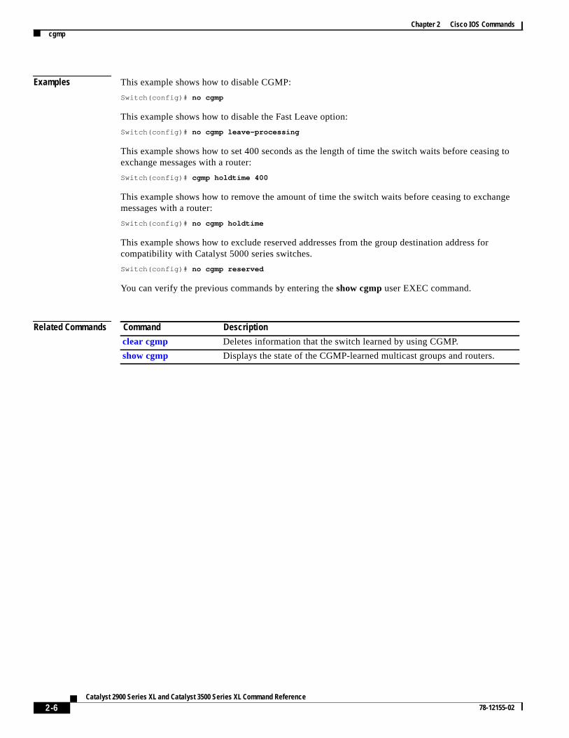
Examples This example shows how to disable CGMP:
Switch(config)# no cgmp
This example shows how to disable the Fast Leave option:
Switch(config)# no cgmp leave-processing
This example shows how to set 400 seconds as the length of time the switch waits before ceasinexchange messages with a router:
Switch(config)# cgmp holdtime 400
This example shows how to remove the amount of time the switch waits before ceasing to exchamessages with a router:
Switch(config)# no cgmp holdtime
This example shows how to exclude reserved addresses from the group destination address forcompatibility with Catalyst 5000 series switches.
Switch(config)# no cgmp reserved
You can verify the previous commands by entering theshow cgmp user EXEC command.
Related Commands Command Description
clear cgmp Deletes information that the switch learned by using CGMP.
show cgmp Displays the state of the CGMP-learned multicast groups and routers.
2-6Catalyst 2900 Series XL and Catalyst 3500 Series XL Command Reference
78-12155-02

Chapter 2 Cisco IOS Commandsclear cgmp
by
clear cgmpUse theclear cgmpprivileged EXEC command to delete information that was learned by the switchusing the Cisco Group Management Protocol (CGMP).
clear cgmp [vlan vlan-id] | [group [address] | router [address]]
Syntax Description
Command Modes Privileged EXEC
Command History
Usage Guidelines Usingclear cgmp with no arguments deletes all groups and routers in all VLANs.
Examples This example shows how to delete all groups and routers on VLAN 2:
Switch# clear cgmp vlan 2
This example shows how to delete all groups on all VLANs:
Switch# clear cgmp group
This example shows how to delete a router address on VLAN 2:
Switch# clear cgmp vlan 2 router 0012.1234.1234
You can verify the previous commands by entering theshow cgmp user EXEC command.
Related Commands
vlan vlan-id (Optional) VLAN for which the CGMP groups or routers are to be deleted.Valid IDs are from 1 to 1001; do not enter leading zeroes.
group address Delete all known multicast groups and their destination ports. Limited to aVLAN if the vlan keyword is entered. Limited to a specific group if theaddress parameter (MAC address of the group or router) is entered.
router address (Optional) Delete all routers, their ports, and expiration times. Limited to agiven VLAN if the vlan keyword is entered. Limited to a specific router iftheaddress parameter is entered.
Release Modification
11.2(8)SA3 This command was first introduced.
Command Description
cgmp Enables CGMP and the Fast Leave option and sets the router port agingtime.
show cgmp Displays the state of the CGMP-learned multicast groups and routers.
2-7Catalyst 2900 Series XL and Catalyst 3500 Series XL Command Reference
78-12155-02

Chapter 2 Cisco IOS Commandsclear controllers ethernet-controller
clear controllers ethernet-controllerUse theclear controllers ethernet-controller privileged EXEC command to delete the Ethernet linktransmit and receive statistics on a Fast Ethernet switch.
clear controllers ethernet-controller interface-id
Syntax Description
Defaults No default is defined.
Command Modes Privileged EXEC
Command History
Usage Guidelines Using the clear controllers ethernet-controller command without specifying a Fast Ethernet portdeletes the Ethernet link statistics of all ports on the switch.
It takes the switch several seconds to clear all of the ports.
Examples. This example shows how to use theclear controllers ethernet-controller command to delete theEthernet link statistics on Fast Ethernet port 0/1:
Switch# clear controllers ethernet-controller FastEthernet 0/1Switch#
You can verify that information was deleted by entering theshow controllers ethernet-controlleruserEXEC command.
Related Commands
interface-id ID of the Fast Ethernet port.
Release Modification
12.0(5)WC1 This command was first introduced.
Command Description
show controllersethernet-controller
Displays the Ethernet link transmit and receive statistics on aFast Ethernet.
2-8Catalyst 2900 Series XL and Catalyst 3500 Series XL Command Reference
78-12155-02

Chapter 2 Cisco IOS Commandsclear ip address
hent
clear ip addressUse theclear ip address privileged EXEC command to delete an IP address for a switch withoutdisabling the IP processing.
clear ip address[vlan vlan-id]
Syntax Description
Command Modes Privileged EXEC
Command History
Usage Guidelines A switch can have one IP address.
The IP address of the switch can be accessed only by nodes connected to ports that belong to tmanagement VLAN. By default, the management VLAN is VLAN 1, but you can configure a differeVLAN as the management VLAN.
If your switch receives its IP address from a Bootstrap Protocol (BOOTP) or Dynamic HostConfiguration Protocol (DHCP) server and you delete the switch IP address by using theclear ipaddresscommand, the BOOTP or DHCP server reassigns the address.
Examples This example shows how to clear the IP address for the switch on VLAN 1:
Switch# clear ip address vlan 1
You can verify the previous commands by entering theshow running-config privileged EXECcommand.
Related Commands
vlan vlan-id (Optional) Delete an IP address only within the specified VLAN.Valid IDs are from 1 to 1000; do not enter leading zeroes.
Release Modification
11.2(8)SA This command was first introduced.
11.2(8)SA3 Thevlan keyword was added.
Command Description
show running-config Displays the running configuration on the switch.
2-9Catalyst 2900 Series XL and Catalyst 3500 Series XL Command Reference
78-12155-02

Chapter 2 Cisco IOS Commandsclear mac-address-table
s
ed bytions
clear mac-address-tableUse theclear mac-address-table privileged EXEC command to delete entries from the MAC addrestable.
clear mac-address-table[static | dynamic | secure] [addresshw-addr] [ interface interface][atm slot/port] [vlan vlan-id]
Syntax Description
Command Modes Privileged EXEC
Command History
Usage Guidelines This command deletes entries from the global MAC address table. Specific subsets can be deletusing the optional keywords and values. If more than one optional keyword is used, all of the condiin the argument must be true for that entry to be deleted.
static (Optional) Delete only static addresses.
dynamic (Optional) Delete only dynamic addresses.
secure (Optional) Delete only secure addresses.
addresshw-addr (Optional) Delete the addresshw-addrof type static, dynamic, and secureas specified.
interface interface (Optional) Delete an address on the interfaceinterfaceof type static,dynamic, or secure as specified.
atm slot/port (Optional) Delete only ATM addresses on this slot and port.
vlan vlan-id (Optional) Delete all the MAC addresses forvlan-id. Valid IDs are from1 to 1005; do not enter leading zeroes.
Release Modification
11.2(8)SA This command was first introduced.
11.2(8)SA3 Thevlan keyword was added.
11.2(8)SA5 Theatm keyword was added.
2-10Catalyst 2900 Series XL and Catalyst 3500 Series XL Command Reference
78-12155-02

Chapter 2 Cisco IOS Commandsclear mac-address-table
ress
ATM
ort in
Examples This example shows how to delete static addresses on port fa0/7:
Switch# clear mac-address-table static interface fa0/7
This example shows how to delete all secure addresses in VLAN 3:
Switch# clear mac-address-table secure vlan 3
This example shows how to delete address 0099.7766.5544 from all ports in all VLANs. If the addexists in multiple VLANs or multiple ports, all the instances are deleted.
Switch# clear mac-address-table address 0099.7766.5544
This example shows how to delete address 0099.7766.5544 only in VLAN 2:
Switch# clear mac-address-table address 0099.7766.5544 vlan 2
This example shows how to delete the secure MAC address 00c0.00a0.03fa associated with theport in expansion slot 2:
Switch(config)# clear mac-address-table secure 00c0.00a0.03fa atm 2/1
This example shows how to delete the static address 00c0.00a0.03fa associated with the ATM pexpansion slot 2:
Switch(config)# clear mac-address-table static 00c0.00a0.03fa atm 2/1
You can verify the previous commands by entering theshow mac-address-tableuser EXEC command.
Related Commands Command Description
show mac-address-table Displays the MAC address table.
2-11Catalyst 2900 Series XL and Catalyst 3500 Series XL Command Reference
78-12155-02

Chapter 2 Cisco IOS Commandsclear mac-address-table notification
nd the
clear mac-address-table notificationUse theclear mac-address-table notificationprivileged EXEC command to clear the addressesmaintained by the MAC address notification feature.
clear mac-address-table notification
Syntax Description This command has no keywords or options.
Command Modes Privileged EXEC
Command History
Usage Guidelines This command clears the counters for the MAC addresses added, the MAC addresses removed, anumber of traps sent to the NMS counters on the switch. This command doesnot clear the history tableon the switch.
Related Commands
Release Modification
12.0(5)WC3 This feature was added.
Command Description
show mac-address-table Displays the MAC address table.
2-12Catalyst 2900 Series XL and Catalyst 3500 Series XL Command Reference
78-12155-02

Chapter 2 Cisco IOS Commandsclear vmps statistics
N
clear vmps statisticsUse theclear vmps statisticsprivileged EXEC command to clear the statistics maintained by the VLAQuery Protocol (VQP) client.
clear vmps statistics
Syntax Description This command has no arguments or keywords.
Command Modes Privileged EXEC
Command History
Examples This example shows how to clear VLAN Membership Policy Server (VMPS) statistics:
Switch# clear vmps statistics
You can verify the previous command by entering theshow vmps statisticsprivileged EXEC command.
Related Commands
Release Modification
11.2(8)SA4 This command was first introduced.
Command Description
show vmps statistics Displays the VLAN Query Protocol (VQP) version, reconfirmation interval,retry count, VMPS IP addresses, and the current and primary servers.
2-13Catalyst 2900 Series XL and Catalyst 3500 Series XL Command Reference
78-12155-02
Chapter 2 Cisco IOS Commandsclear vtp counters
d
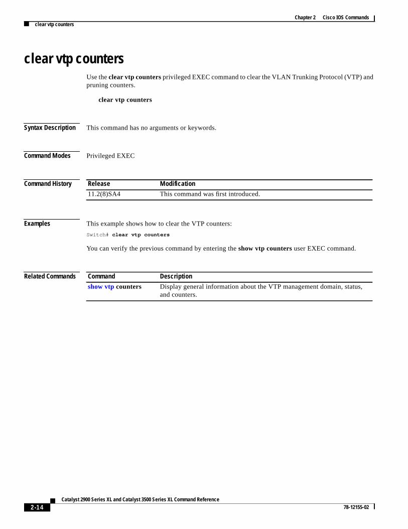
clear vtp countersUse theclear vtp countersprivileged EXEC command to clear the VLAN Trunking Protocol (VTP) anpruning counters.
clear vtp counters
Syntax Description This command has no arguments or keywords.
Command Modes Privileged EXEC
Command History
Examples This example shows how to clear the VTP counters:
Switch# clear vtp counters
You can verify the previous command by entering theshow vtp countersuser EXEC command.
Related Commands
Release Modification
11.2(8)SA4 This command was first introduced.
Command Description
show vtp counters Display general information about the VTP management domain, status,and counters.
2-14Catalyst 2900 Series XL and Catalyst 3500 Series XL Command Reference
78-12155-02

Chapter 2 Cisco IOS Commandscluster commander-address
ressn and
g or
the
onlytion,
cluster
cluster commander-addressYou do not need to enter this command. The command switch automatically provides its MAC addto member switches when these switches join the cluster. The member switch adds this informatioother cluster information to its running configuration file. Enter theno form of this global configurationcommand from the member switch console port to remove it from a cluster only during debugginrecovery procedures.
cluster commander-addressmac-address[member numbername name]
no cluster commander-address
Syntax Description
Defaults The switch is not a member of any cluster.
Command Modes Global configuration
Command History
Usage Guidelines A cluster member can belong to only one command switch.
The member switch retains the identity of the command switch during a system reload by using mac-address parameter.
You can enter theno form on a member switch to remove it from the cluster during debugging orrecovery procedures. You would normally use this command from the member switch console portwhen the member has lost communication with the command switch. With normal switch configurawe recommend that you remove member switches only by entering theno cluster membern globalconfiguration command on the command switch.
When a standby command-switch becomes active (becomes the command switch), it removes thecommander-address line from its configuration.
mac-address MAC address of the cluster command switch.
member number Number of member switch. The range is from 0 to 15.
namename Name of the cluster up to 31 characters.
no Remove a switch from the cluster. Entered on the member switch.
default Remove a switch from the cluster. Entered on the member switch.
Release Modification
11.2(8)SA6 This command was first introduced.
12.0(5)XU Themember andname keywords were added.
2-15Catalyst 2900 Series XL and Catalyst 3500 Series XL Command Reference
78-12155-02

Chapter 2 Cisco IOS Commandscluster commander-address
sole.
h
Examples This is partial sample output from the running configuration of a cluster member.
Switch(config)# show running-configuration
<output truncated>
cluster commander-address 00e0.9bc0.a500 member 4 name my_cluster
<output truncated>
This example shows how to remove a member from the cluster by using the cluster member con
Switch-es3# configure terminalEnter configuration commands, one per line. End with CNTL/Z.Switch-es3(config)# no cluster commander-address
You can verify the previous command by entering theshow cluster command in user EXEC mode.
Related Commands Command Description
show cluster Displays the cluster status and a summary of the cluster to which the switcbelongs.
2-16Catalyst 2900 Series XL and Catalyst 3500 Series XL Command Reference
78-12155-02

Chapter 2 Cisco IOS Commandscluster discovery hop-count
e
itches.
en the
nd
e
cluster discovery hop-countUse thecluster discovery hop-countglobal configuration command on the command switch to set thhop-count limit for extended discovery of candidate switches. Use theno form of this command to setthe hop count to the default value.
cluster discovery hop-countnumber
no cluster discovery hop-count
default cluster discovery hop-count
Syntax Description
Defaults The hop count is set to 3.
Command Modes Global configuration
Command History
Usage Guidelines Enter this command only on the command switch. This command does not operate on member sw
If the hop count is set to 1, it disables extended discovery. The command switch discovers onlycandidates that are one hop from the edge of the cluster. The edge of the cluster is the point betwelast discovered member switch and the first discovered candidate switch.
Examples This example shows how to set the hop count limit to 4. This command is entered on the commaswitch.
Switch(config)# cluster discovery hop-count 4
You can verify the previous command by entering theshow cluster command in user EXEC mode.
Related Commands
number Number of hops from the cluster edge that the command switch limits thdiscovery of candidates. The range is from 1 to 7.
no Set the hop count to the default value (3).
default Set the hop count to the default value (3).
Release Modification
12.0(5)XU This command was first introduced.
Command Description
show cluster Displays the cluster status and a summary of the cluster to which theswitch belongs.
show cluster candidates Displays a list of candidate switches.
2-17Catalyst 2900 Series XL and Catalyst 3500 Series XL Command Reference
78-12155-02
Chapter 2 Cisco IOS Commandscluster enable
these thewitch.
fails
ed asname.
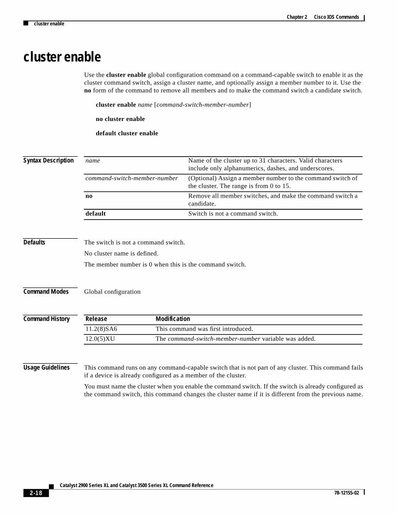
cluster enableUse thecluster enableglobal configuration command on a command-capable switch to enable it ascluster command switch, assign a cluster name, and optionally assign a member number to it. Uno form of the command to remove all members and to make the command switch a candidate s
cluster enablename[command-switch-member-number]
no cluster enable
default cluster enable
Syntax Description
Defaults The switch is not a command switch.
No cluster name is defined.
The member number is 0 when this is the command switch.
Command Modes Global configuration
Command History
Usage Guidelines This command runs on any command-capable switch that is not part of any cluster. This commandif a device is already configured as a member of the cluster.
You must name the cluster when you enable the command switch. If the switch is already configurthe command switch, this command changes the cluster name if it is different from the previous
name Name of the cluster up to 31 characters. Valid charactersinclude only alphanumerics, dashes, and underscores.
command-switch-member-number (Optional) Assign a member number to the command switch ofthe cluster. The range is from 0 to 15.
no Remove all member switches, and make the command switch acandidate.
default Switch is not a command switch.
Release Modification
11.2(8)SA6 This command was first introduced.
12.0(5)XU Thecommand-switch-member-number variable was added.
2-18Catalyst 2900 Series XL and Catalyst 3500 Series XL Command Reference
78-12155-02

Chapter 2 Cisco IOS Commandscluster enable
mand
h
Examples This example shows how to enable the command switch, to name the cluster, and to set the comswitch member number to 4.
Switch(config)# cluster enable Engineering-IDF4 4
You can verify the previous command by entering theshow clustercommand in user EXEC mode onthe command switch.
Related Commands Command Description
show cluster Displays the cluster status and a summary of the cluster to which the switcbelongs.
2-19Catalyst 2900 Series XL and Catalyst 3500 Series XL Command Reference
78-12155-02
Chapter 2 Cisco IOS Commandscluster holdtime
n in after
.
ow to
)
h
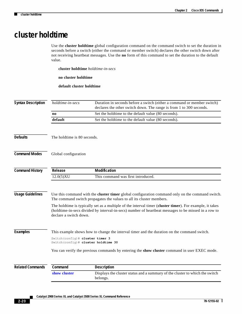
cluster holdtimeUse thecluster holdtime global configuration command on the command switch to set the duratioseconds before a switch (either the command or member switch) declares the other switch downnot receiving heartbeat messages. Use theno form of this command to set the duration to the defaultvalue.
cluster holdtime holdtime-in-secs
no cluster holdtime
default cluster holdtime
Syntax Description
Defaults The holdtime is 80 seconds.
Command Modes Global configuration
Command History
Usage Guidelines Use this command with thecluster timer global configuration command only on the command switchThe command switch propagates the values to all its cluster members.
The holdtime is typically set as a multiple of the interval timer (cluster timer). For example, it takes(holdtime-in-secs divided by interval-in-secs) number of heartbeat messages to be missed in a rdeclare a switch down.
Examples This example shows how to change the interval timer and the duration on the command switch.
Switch(config)# cluster timer 3Switch(config)# cluster holdtime 30
You can verify the previous commands by entering theshow cluster command in user EXEC mode.
Related Commands
holdtime-in-secs Duration in seconds before a switch (either a command or member switchdeclares the other switch down. The range is from 1 to 300 seconds.
no Set the holdtime to the default value (80 seconds).
default Set the holdtime to the default value (80 seconds).
Release Modification
12.0(5)XU This command was first introduced.
Command Description
show cluster Displays the cluster status and a summary of the cluster to which the switcbelongs.
2-20Catalyst 2900 Series XL and Catalyst 3500 Series XL Command Reference
78-12155-02

Chapter 2 Cisco IOS Commandscluster management-vlan
het
cluster management-vlanUse thecluster management-vlanglobal configuration command on the command switch to change tmanagement VLAN for the entire cluster. Use theno form of this command to change the managemenVLAN to VLAN 1.
cluster management-vlann
no cluster management-vlan
default cluster management-vlan
Syntax Description
Defaults The default management VLAN is VLAN 1.
Command Modes Global configuration
Command History
Usage Guidelines Enter this command only on the command switch.
This command is not written to the configuration file.
Examples This example shows how to change the management VLAN to VLAN 5 on the entire cluster.
Switch(config)# cluster management-vlan 5
You can verify the previous command by entering theshow interface vlannumberuser EXECcommand.
Related Commands
n VLAN ID of the new management VLAN. Valid VLAN IDs are from 1 to 1001.
no Set the management VLAN to VLAN 1.
default Set the management VLAN to VLAN 1.
Release Modification
12.0(5)XU This command was first introduced.
Command Description
management Shuts down the management VLAN interface and enables the newmanagement VLAN interface on an individual switch.
2-21Catalyst 2900 Series XL and Catalyst 3500 Series XL Command Reference
78-12155-02

Chapter 2 Cisco IOS Commandscluster member
o a
the
mber
uster.mes a
r to the
cluster memberUse thecluster member global configuration command on the command switch to add members tcluster. Use theno form of the command to remove members from the cluster.
cluster member [n] mac-addressH.H.H [passwordenable-password]
no cluster membern
default cluster membern
Syntax Description
Defaults A newly enabled command switch has no associated cluster members.
Command Modes Global configuration
Command History
Usage Guidelines Enter this command only on the command switch to add a member to or remove a member fromcluster. If a switch is not commanding a cluster, this command displays an error message.
You do not need to enter a member number. The command switch selects the next available menumber and assigns it to the switch joining the cluster.
You must enter the enable password of the candidate switch for authentication when it joins the clThe password is not saved in the running or startup configuration. After a candidate switch becomember of the cluster, its password becomes the same as the command-switch password.
If a switch does not have a configured host name, the command switch appends a member numbecommand-switch host name and assigns it to the member switch.
n (Optional) The number that identifies a cluster member. The rangeis from 0 to 15.
mac-addressH.H.H MAC address of the member switch in hexadecimal format.
passwordenable-password Enable password of the candidate switch. The password is notrequired if there is no password on the candidate switch.
no Remove the specified member from the cluster.
default Remove the specified member from the cluster.
Release Modification
11.2(8)SA6 This command was first introduced.
2-22Catalyst 2900 Series XL and Catalyst 3500 Series XL Command Reference
78-12155-02

Chapter 2 Cisco IOS Commandscluster member
the
he
e
Examples This example shows how to add a switch as member 2 with MAC address 00E0.1E00.2222 and password grandkey to a cluster.
Switch(config)# cluster member 2 mac-address 00E0.1E00.2222 password grandkey
This example shows how to add a switch with MAC address 00E0.1E00.3333 to the cluster. Thecommand switch selects the next available member number and assigns it to the switch joining tcluster.
Switch(config)# cluster member mac-address 00E0.1E00.3333
You can verify the previous command by entering theshow cluster memberscommand in user EXECmode on the command switch.
Related Commands Command Description
show cluster Displays the cluster status and a summary of the cluster to which thswitch belongs.
show cluster candidates Displays a list of candidate switches.
show cluster members Displays information about the cluster members.
2-23Catalyst 2900 Series XL and Catalyst 3500 Series XL Command Reference
78-12155-02

Chapter 2 Cisco IOS Commandscluster run
d.
h
cluster runUse thecluster run global configuration command to enable clustering on a switch. Use theno form ofthis command to disable clustering on a switch.
cluster run
no cluster run
default cluster run
Syntax Description
Defaults Clustering is enabled on all switches.
Command Modes Global configuration
Command History
Usage Guidelines When you enter theno cluster run command on a command switch, the command switch is disableClustering is disabled, and the switch is incapable of becoming a candidate switch.
When you enter theno cluster run command on a member switch, it is removed from the cluster.Clustering is disabled, and the switch is incapable of becoming a candidate switch.
When you enter theno cluster run command on a switch that is not part of a cluster, clustering isdisabled on this switch. This switch cannot then become a candidate switch.
Examples This example shows how to disable clustering on the command switch:
Switch(config)# no cluster run
You can verify the previous command by entering theshow cluster command in user EXEC mode.
Related Commands
no Disable clustering on a switch.
default Enable clustering on a switch.
Release Modification
12.0(5)XU This command was first introduced.
Command Description
show cluster Displays the cluster status and a summary of the cluster to which the switcbelongs.
2-24Catalyst 2900 Series XL and Catalyst 3500 Series XL Command Reference
78-12155-02
Chapter 2 Cisco IOS Commandscluster setup
n switch
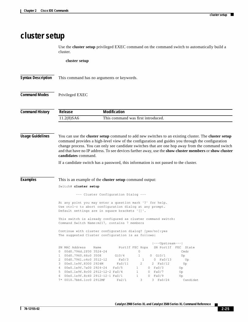
cluster setupUse thecluster setup privileged EXEC command on the command switch to automatically build acluster.
cluster setup
Syntax Description This command has no arguments or keywords.
Command Modes Privileged EXEC
Command History
Usage Guidelines You can use thecluster setup command to add new switches to an existing cluster. Thecluster setupcommand provides a high-level view of the configuration and guides you through the configuratiochange process. You can only see candidate switches that are one hop away from the commandand that have no IP address. To see devices farther away, use theshow cluster membersor show clustercandidates command.
If a candidate switch has a password, this information is not passed to the cluster.
Examples This is an example of thecluster setup command output:
Switch# cluster setup
--- Cluster Configuration Dialog ---
At any point you may enter a question mark '?' for help.Use ctrl-c to abort configuration dialog at any prompt.Default settings are in square brackets '[]'.
This switch is already configured as cluster command switch:Command Switch Name:m217, contains 7 members
Continue with cluster configuration dialog? [yes/no]:yesThe suggested Cluster configuration is as follows:
|---Upstream---|SN MAC Address Name PortIf FEC Hops SN PortIf FEC State0 00d0.796d.2f00 3524-24 0 Cmdr1 00d0.7960.66c0 3508 Gi0/4 1 0 Gi0/1 Up2 00d0.7961.c4c0 3512-12 Fa0/3 1 0 Fa0/13 Up3 00e0.1e9f.8300 2924M Fa0/11 2 2 Fa0/12 Up4 00e0.1e9f.7a00 2924-24 Fa0/5 1 0 Fa0/3 Up5 00e0.1e9f.8c00 2912-12-2 Fa0/4 1 0 Fa0/7 Up6 00e0.1e9f.8c40 2912-12-1 Fa0/1 1 0 Fa0/9 Up7* 0010.7bb6.1cc0 2912MF Fa2/1 3 3 Fa0/24 Candidat
Release Modification
11.2(8)SA6 This command was first introduced.
2-25Catalyst 2900 Series XL and Catalyst 3500 Series XL Command Reference
78-12155-02

Chapter 2 Cisco IOS Commandscluster setup
e,
The following configuration command script was created:cluster member 7 mac-address 0010.7bb6.1cc0!end
Use this configuration? [yes/no]:yes
Building configuration...[OK]Use the enabled mode 'configure' command to modify this configuration.
Switch#
You can verify your settings by entering theshow cluster user EXEC command.
Related Commands Command Description
cluster enable Enables a switch as the cluster command switch, assigns a cluster namand optionally assigns a member number to it.
show cluster Displays the cluster status and a summary of the cluster to which theswitch belongs.
show cluster candidates Displays a list of candidate switches.
show cluster members Displays information about the cluster members.
2-26Catalyst 2900 Series XL and Catalyst 3500 Series XL Command Reference
78-12155-02
Chapter 2 Cisco IOS Commandscluster standby-group
ncy
error
mber
ror.
cluster standby-groupUse thecluster standby-group global configuration command to enable command switch redundaby binding the Hot Standby Router Protocol (HSRP) standby group to the cluster. Use theno form ofthis command to unbind the cluster from the HSRP standby group.
cluster standby-groupHSRP-group-name
no cluster standby-group
default cluster standby-group
Syntax Description
Defaults The cluster is not bound to any HSRP group.
Command Modes Global configuration
Command History
Usage Guidelines You must enter this command only on the command switch. If you enter it on a member switch, anmessage appears.
The command switch propagates the cluster-HSRP binding information to all members. Each meswitch stores the binding information in its nonvolatile RAM (NVRAM).
The HSRP group name must be a valid standby group; otherwise, the command exits with an er
HSRP-group-name Name of the HSRP group that is bound to the cluster. The group name islimited to 32 characters.
no Unbind the cluster from the HSRP standby group.
default Unbind the cluster from the HSRP standby group.
Release Modification
12.0(5)XU This command was first introduced.
2-27Catalyst 2900 Series XL and Catalyst 3500 Series XL Command Reference
78-12155-02

Chapter 2 Cisco IOS Commandscluster standby-group
is
d the
h
Examples This example shows how to bind the HSRP group named my_hsrp to the cluster. This commandentered on the command switch.
Switch(config)# cluster standby-group my_hsrp
This example shows the error message when this command is entered on a command switch anspecified HSRP standby group does not exist:
Switch(config)# cluster standby-group my_hsrp%ERROR: Standby group ‘my_hsrp’ doesn’t exist
This example shows the error message when this command is entered on a member switch.
Switch(config)# cluster standby-group my_hsrp%ERROR: This command runs only on the command switch
You can verify the previous commands by entering theshow cluster command in user EXEC mode.
Related Commands Command Description
standby ip Enables HSRP on the interface.
show cluster Displays the cluster status and a summary of the cluster to which the switcbelongs.
show standby Displays standby group information.
2-28Catalyst 2900 Series XL and Catalyst 3500 Series XL Command Reference
78-12155-02

Chapter 2 Cisco IOS Commandscluster timer
t
sed in
witch.
00
h
cluster timerUse thecluster timer global configuration command on the command switch to set the interval inseconds between heartbeat messages. Use theno form of this command to set the interval to the defaulvalue.
cluster timer interval-in-secs
no cluster timer
default cluster timer
Syntax Description
Defaults The interval is 8 seconds.
Command Modes Global configuration
Command History
Usage Guidelines Use this command with thecluster holdtime global configuration command only on the commandswitch. The command switch propagates the values to all its cluster members.
The holdtime is typically set as a multiple of the heartbeat interval timer (cluster timer). For example,it takes (holdtime-in-secs divided by the interval-in-secs) number of heartbeat messages to be misa row to declare a switch down.
Examples This example shows how to change the heartbeat interval timer and the duration on the command s
Switch(config)# cluster timer 3Switch(config)# cluster holdtime 30
You can verify the previous commands by entering theshow clusteruser EXEC command.
Related Commands
interval-in-secs Interval in seconds between heartbeat messages. The range is from 1 to 3seconds.
no Set the interval to the default value (8 seconds).
default Set the interval to the default value (8 seconds).
Release Modification
12.0(5)XU This command was first introduced.
Command Description
show cluster Displays the cluster status and a summary of the cluster to which the switcbelongs.
2-29Catalyst 2900 Series XL and Catalyst 3500 Series XL Command Reference
78-12155-02

Chapter 2 Cisco IOS Commandsdelete
deleteUse thedelete privileged EXEC command to delete a file from the file system.
delete {device:} filename
Syntax Description
Command Modes Privileged EXEC
Command History
Usage Guidelines A colon (:) follows thedevice variable. Do not enter spaces after the colon.
Examples This example shows how to delete the fileatm_image from the file system for an ATMmodule installed in slot 1:
Switch# delete slot1:atm_image
This example shows how to delete a file from the switch Flash memory:
Switch# delete flash:filename
You can verify that the file was removed by entering theshow flash:user EXEC command.
Related Commands
device: Device containing the file to be deleted. Valid devices include the switchFlash memory and Asynchronous Transfer Mode (ATM) module files. Toaccess the ATM module, specify the slot number (1 or 2).
filename Name of file.
Release Modification
11.2(8)SA6 This command was first introduced.
Command Description
copy tftp Downloads a file from a TFTP server to a device.
2-30Catalyst 2900 Series XL and Catalyst 3500 Series XL Command Reference
78-12155-02
Chapter 2 Cisco IOS Commandsduplex
peed
duplexUse theduplex interface configuration command to specify the duplex mode of operation for FastEthernet and Gigabit Ethernet ports. Use theno form of this command to return the port to its defaultvalue.
duplex { full | half | auto}
no duplex
Syntax Description
Defaults The default isauto.
Command Modes Interface configuration
Command History
Usage Guidelines Certain ports can be configured as either full duplex or half duplex. Applicability of this commanddepends on the device to which the switch is attached.
For Fast Ethernet ports, setting the port toauto has the same effect as specifyinghalf if the attacheddevice does not autonegotiate the duplex parameter.
For Gigabit Ethernet ports, setting the port toauto has the same effect as specifyingfull if the attacheddevice does not autonegotiate the duplex parameter.
If the speed is set to auto, the switch negotiates with the device at the other end of the link for the ssetting and then forces the speed setting to the negotiated value. The duplex setting remains asconfigured on each end of the link, which could result in a duplex setting mismatch.
If both the speed and duplex are set to specific values, autonegotiation is disabled.
Note For guidelines on setting the switch speed and duplex parameters, see theCatalyst 2900 Series XLHardware Installation Guideand the Catalyst 3500 Series XL Hardware Installation Guide.
This command is not supported on the ATM module.
full Port is in full-duplex mode.
half Port is in half-duplex mode.
auto Port automatically detects whether it should run in full- or half-duplex mode.
Release Modification
11.2(8)SA This command was first introduced.
2-31Catalyst 2900 Series XL and Catalyst 3500 Series XL Command Reference
78-12155-02

Chapter 2 Cisco IOS Commandsduplex
:
lex:
Examples This example shows how to set port 1 on a Fast Ethernet module installed in slot 2 to full duplex
Switch(config)# interface fastethernet2/1Switch(config-if)# duplex full
This example shows how to set port 1 on a Gigabit Ethernet module installed in slot 2 to full dup
Switch(config)# interface gigabitethernet2/1Switch(config-if)# duplex full
You can verify the previous commands by entering theshow running-config privileged EXECcommand.
Related Commands Command Description
show running-config Displays the running configuration on the switch.
speed Specifies the speed of a Fast Ethernet port.
2-32Catalyst 2900 Series XL and Catalyst 3500 Series XL Command Reference
78-12155-02

Chapter 2 Cisco IOS Commandsexit
thern to
ANged
EC
exitUse theexit VLAN database command to implement the proposed VLAN database, to increment database configuration number, to propagate it throughout the administrative domain, and to retuprivileged EXEC mode.
exit
Syntax Description This command has no arguments or keywords.
Defaults No default is defined.
Command Modes VLAN database
Command History
Usage Guidelines Theexit command implements all the configuration changes that you made since you entered VLdatabase mode and uses them for the running configuration. This command returns you to privileEXEC mode.
Examples This example shows how to implement the proposed VLAN database and to exit to privileged EXmode:
Switch(vlan)# exitSwitch#
You can verify the previous command by entering theshow vlan brief user EXEC command.
Release Modification
11.2(8)SA4 This command was first introduced.
2-33Catalyst 2900 Series XL and Catalyst 3500 Series XL Command Reference
78-12155-02

Chapter 2 Cisco IOS Commandsexit
d
Related Commands Command Description
abort Abandons the proposed VLAN database, exits VLAN database mode, anreturns to privileged EXEC mode.
apply Implements the proposed VLAN database, increments the databaseconfiguration revision number, propagates it throughout the administrativedomain, and remains in VLAN database mode.
reset Abandons the proposed VLAN database and remains in VLAN databasemode. Resets the proposed database to the currently implemented VLANdatabase on the switch.
show vlan Displays the parameters for all configured VLANs in the administrativedomain.
shutdown vlan Shuts down (suspends) local traffic on the specified VLAN.
vlan database Enters VLAN database mode from the command-line interface (CLI).
2-34Catalyst 2900 Series XL and Catalyst 3500 Series XL Command Reference
78-12155-02

Chapter 2 Cisco IOS Commandsflowcontrol
tes
ote
t:
rt
flowcontrolUse theflowcontrol interface configuration command on Gigabit Ethernet ports to control traffic raduring congestion. Use theno form of this command to disable flow control on the port.
flowcontrol { asymmetric | symmetric}
no flowcontrol
Syntax Description
Defaults The default is asymmetric.
Command Modes Interface configuration
Command History
Examples This example shows how to configure the local port to support any level of flow control by the remport:
Switch(config-if)# flowcontrol
This example shows how to configure the local port to control the traffic flow from the remote por
Switch(config-if)# flowcontrol asymmetric
You can verify the previous commands by entering theshow running-config privileged EXECcommand.
Related Commands
asymmetric Enable the local port to perform flow control of the remote port. If the local portis congested, it can request the remote port to stop transmitting. The local porequests that the remote port begin transmitting after the congestion clears.
symmetric Enable the local port to perform flow control only if the remote port can alsoperform flow control of the local port. If the remote port cannot perform flowcontrol, the local port also does not.
Release Modification
11.2(8)SA6 This command was first introduced.
Command Description
show interface [interface-id]flow-control
Displays flow-control information for the specified port.
2-35Catalyst 2900 Series XL and Catalyst 3500 Series XL Command Reference
78-12155-02
Chapter 2 Cisco IOS Commandsinterface
ualde.
to
, and
t,
interfaceUse theinterface global configuration command to configure an interface type, to create a switch virtinterface to be used as the management VLAN interface, and to enter interface configuration mo
interface type slot/port | vlan number
no interface type slot/port | vlan number
Syntax Description
Defaults The default management VLAN interface is VLAN 1.
Command Modes Global configuration
Command History
Usage Guidelines When creating a management VLAN interface, a space betweenvlan andnumberis accepted.
Only one management VLAN interface can be active.
You cannot delete the management VLAN 1 interface.
Before bringing up a new management VLAN interface with theno shutdowncommand, you must entertheshutdown command to disable the old one.
You can use themanagement command to shut down the active management VLAN interface and enable the newly created management VLAN interface.
You can configure the management VLAN interface on static-access, multi-VLAN, dynamic-accesstrunk ports.
type Type of interface to be configured. Can be Fast Ethernet, Gigabit Etherneor Asynchronous Transfer Mode (ATM).
slot Slot number (0, 1, or 2). For an ATM module, use slot number 1 or 2.
port Port ID.
vlan number VLAN number from 1 to 1001 to be used as the management VLAN. Donot enter leading zeroes.
Release Modification
11.2(8)SA This command was first introduced.
11.2(8)SA3 Thevlan keyword was added.
2-36Catalyst 2900 Series XL and Catalyst 3500 Series XL Command Reference
78-12155-02

Chapter 2 Cisco IOS Commandsinterface
ries
net
ent
w
Examples This example shows how to enable the switch to act on ATM interface 1/2:
Switch(config)# interface atm 1/2Switch(config-if)#
This example shows how to change the management VLAN from VLAN 1 to VLAN 3. Enter this seof commands only from the console. If you enter these commands through a Telnet session, theshutdown command disconnects the session, and you cannot to use IP to access the system.
Switch# configure terminalSwitch(config)# interface vlan 3Switch(config-subif)# ip address 172.20.128.176 255.255.255.0Switch(config-subif)# exitSwitch(config-if)# exitSwitch(config)# interface vlan 1Switch(config-subif)# shutdownSwitch(config-subif)# exitSwitch(config-if)# exitSwitch(config)# interface vlan 3Switch(config-subif)# no shutdownSwitch(config-subif)# exitSwitch(config-if)# exit
This example shows how to change the management VLAN from VLAN 1 to VLAN 3 through a Telsession. In this situation, themanagementcommand shuts down VLAN 1 and brings up VLAN 3. TheTelnet session must be re-established through the new management VLAN.
Switch# configure terminalSwitch(config)# interface vlan 3Switch(config-subif)# ip address 172.20.128.176 255.255.255.0Switch(config-subif)# management
This example shows how to copy the IP address and the network mask information from the currmanagement VLAN to VLAN 3 and to make VLAN 3 the new management VLAN:
Switch# configure terminalSwitch(config)# interface vlan 3Switch(config-subif)# management
You can verify the previous commands by entering theshow interfaceandshow interface vlannumbercommands in user EXEC mode.
Related Commands Command Description
management Shuts down the current management VLAN interface and enables the nemanagement VLAN interface.
show interface Displays the administrative and operational status of a switching(nonrouting) port.
shutdown Disables a port and shuts down the management VLAN.
2-37Catalyst 2900 Series XL and Catalyst 3500 Series XL Command Reference
78-12155-02

Chapter 2 Cisco IOS Commandsip address
ent
.
ss.
.
ip addressUse theip addressinterface configuration command to set an IP address for a switch. Use theno formof this command to remove an IP address or to disable IP processing.
ip address ip-address subnet-mask
no ip addressip-address subnet-mask
Syntax Description
Defaults No IP address is defined for the switch.
Command Modes Interface configuration
Command History
Usage Guidelines A switch can have one IP address.
The IP address of the switch can be accessed only by nodes connected to ports that belong to thmanagement VLAN. By default, the management VLAN is VLAN 1, but you can configure a differeVLAN as the management VLAN.
If you remove the IP address through a Telnet session, your connection to the switch will be lost
If your switch receives its IP address from a Bootstrap Protocol (BOOTP) or Dynamic HostConfiguration Protocol (DHCP) server and you remove the switch IP address by using theno ip addresscommand, IP processing is disabled, and the BOOTP or DHCP server cannot reassign the addre
Examples This example shows how to configure the IP address for the switch on a subnetted network:
Switch(config)# interface vlan 1Switch(config-if)# ip address 172.20.128.2 255.255.255.0
You can verify the previous commands by entering theshow running-config privileged EXECcommand.
Related Commands
ip-address IP address.
subnet-mask Mask for the associated IP subnet.
Release Modification
11.2(8)SA This command was first introduced.
Command Description
show running-config Displays the running configuration on the switch.
clear ip address Deletes an IP address for a switch without disabling the IP processing
2-38Catalyst 2900 Series XL and Catalyst 3500 Series XL Command Reference
78-12155-02

Chapter 2 Cisco IOS Commandsip igmp filter
e IP
ip igmp filterUse theip igmp filter interface configuration command to apply an Internet Group ManagementProtocol (IGMP) profile to an interface and to prevent hosts on an interface from joining one or mormulticast groups. Use theno form of this command to remove a specified profile from an interface.
ip igmp filter profile number
no ip igmp filter profile number
Syntax Description
Defaults No IGMP filtering profiles are assigned to an interface.
Command Modes Interface configuration
Command History
Usage Guidelines The same IGMP profile can be applied to more than one switch port interface.
Examples This example shows how to apply an IGMP filtering profile to an interface:
Switch(config-if)# ip igmp filter 30
You can verify your settings by entering theshow ip igmp profile profile numberuser EXEC command.
Related Commands
profile number The range is from 1 to 4294967295.
Release Modification
12.0(5)WC3 This command was first introduced.
Command Description
ip igmp profile Defines a new IGMP filtering profile.
show ip igmp profile Displays the details of an IGMP filtering profileentry.
show running-config interfaceinterface name Displays the running configuration on the switch,including any profiles assigned to a port.
2-39Catalyst 2900 Series XL and Catalyst 3500 Series XL Command Reference
78-12155-02

Chapter 2 Cisco IOS Commandsip igmp max-groups
ip igmp max-groupsUse theip igmp max-groups interface configuration command to specify the maximum number ofInternet Group Management Protocol (IGMP) groups that can be active on a port.
ip igmp max-groupsnumber
Syntax Description
Defaults No maximum number of IGMP groups are defined.
Command Modes Interface configuration
Command History
Usage Guidelines There is no limit to the number of multicast groups that a port can join.
If 0 is specified as themaxgroupsvalue for an interface, that interface cannot joinanymulticast groups.
Examples This example shows how to limit the number of IGMP groups that an interface can join to 25.Switch(config)# interface fastethernet 0/12Switch(config-if)# ip igmp max-groups 25
You can verify your setting by using theshow running-configuration privileged EXEC command andby specifying an interface.
Switch# show running-config interface fastethernet 0/12Building configuration...
Current configuration :124 bytes!interface FastEthernet0/12 no ip address shutdown snmp trap link-status ip igmp max-groups 25 ip igmp filter 22end
You can verify your settings by entering theshow running-config interface interface configurationcommand.
number The maximum number of IGMP filtering groups that can be active on a port. Therange is from 0 to 256.
Release Modification
12.0(5)WC3 This command was first introduced.
2-40Catalyst 2900 Series XL and Catalyst 3500 Series XL Command Reference
78-12155-02

Chapter 2 Cisco IOS Commandsip igmp max-groups
Related Commands ip igmp profile Applies an IGMP filtering profile to an interface.
show ip igmp profile Displays the details of an IGMP filtering profile entry.
show running-config interface Displays the running configuration on the switch, including anyprofiles assigned to a port.
2-41Catalyst 2900 Series XL and Catalyst 3500 Series XL Command Reference
78-12155-02

Chapter 2 Cisco IOS Commandsip igmp profile
cify
es in
ords:
e with
ip igmp profileUse theip igmp profile global configuration command to create an Internet Group ManagementProtocol (IGMP) profile and to enter IGMP profile configuration mode. From this mode, you can spethe configuration of the IGMP profile. Use theno form of this command and a profile number to deletean IGMP profile.
ip igmp profile profile number
no ip igmp profile profile number
Syntax Description
Defaults No IGMP profiles are defined. When a profile configured, the default action is to deny the addressthe profile.
Command Modes Global configuration
Command History
Usage Guidelines When you are in IGMP profile configuration mode, you can create the profile by using these keyw
• deny: specifies that matching addresses are denied; this is the default.
• permit : specifies that matching address are permitted.
• range: adds a range to the set range of IP address. This can be a single IP address or a rangstart and end addresses.
• exit: saves changes to the IGMP profile and exits from IGMP profile configuration mode.
• no: negates the command or sets it to the defaults.
Examples This example shows how to create an IGMP filtering profile:
host1# config terminalEnter configuration commands, one per line. End with CNTL/Z.host1(config)# ip igmp profile 30host1(config-igmp-profile)#host1(config-igmp-profile)# denyhost1(config-igmp-profile)# range 233.1.1.1 233.255.255.255host1(config-igmp-profile)# range 235.1.1.1 235.255.255.255host1(config-igmp-profile)# endhost1#
profile number The IGMP profile being created. The range is 1 to 4294967295.
Release Modification
12.0(5)WC3 This command was first introduced.
2-42Catalyst 2900 Series XL and Catalyst 3500 Series XL Command Reference
78-12155-02

Chapter 2 Cisco IOS Commandsip igmp profile
Related Commands Command Description
ip igmp profile Applies an IGMP filtering profile to an interface.
show ip igmp profile Displays the details of an IGMP filtering profile entry.
show running-config interface Displays the running configuration on the switch, including anyprofiles assigned to a port.
2-43Catalyst 2900 Series XL and Catalyst 3500 Series XL Command Reference
78-12155-02

Chapter 2 Cisco IOS Commandslogin authentication
nd
ault.
hod
ng
s.
login authenticationUse thelogin authentication line configuration command to enable authentication, authorization, aaccounting (AAA) for logins. Use theno form of this command to either disable Terminal AccessController Access Control System Plus (TACACS+) authentication for logins or to return to the def
login authentication { default | list-name}
no login { default | list-name}
Syntax Description
Defaults Login authentication is disabled.
Command Modes Line configuration
Command History
Usage Guidelines To create a default list that is used if no list is specified in thelogin authentication command, use thedefault keyword followed by the methods that you want used in default situations. The default metlist is automatically applied to all interfaces.
Examples This example shows how to specify TACACS+ as the default method for user authentication durilogin:
Switch(config)# aaa new-modelSwitch(config)# aaa authentication login default tacacsSwitch(config)# line vty 0 4Switch(config-line)# login authentication default tacacs
You can verify the previous commands by entering theshow running-config privileged EXECcommand.
Related Commands
default Use the default list created with the AAAauthentication login command.
list-name Use the indicated list created with the AAAauthentication login command.
Release Modification
11.2(8)SA6 This command was first introduced.
Command Description
enable password Specifies a local password to control access to various privilege level
password Specifies a password on a line.
show running-config Displays the running configuration on the switch.
username Establishes a username-based authentication system.
2-44Catalyst 2900 Series XL and Catalyst 3500 Series XL Command Reference
78-12155-02
Chapter 2 Cisco IOS Commandsmac-address-table aging-time
a
nger
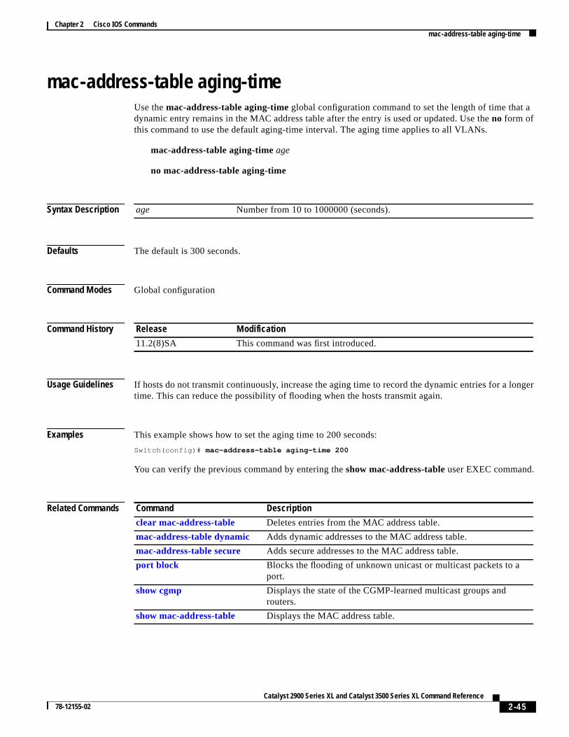
mac-address-table aging-timeUse themac-address-table aging-time global configuration command to set the length of time that dynamic entry remains in the MAC address table after the entry is used or updated. Use theno form ofthis command to use the default aging-time interval. The aging time applies to all VLANs.
mac-address-table aging-timeage
no mac-address-table aging-time
Syntax Description
Defaults The default is 300 seconds.
Command Modes Global configuration
Command History
Usage Guidelines If hosts do not transmit continuously, increase the aging time to record the dynamic entries for a lotime. This can reduce the possibility of flooding when the hosts transmit again.
Examples This example shows how to set the aging time to 200 seconds:
Switch(config)# mac-address-table aging-time 200
You can verify the previous command by entering theshow mac-address-table user EXEC command.
Related Commands
age Number from 10 to 1000000 (seconds).
Release Modification
11.2(8)SA This command was first introduced.
Command Description
clear mac-address-table Deletes entries from the MAC address table.
mac-address-table dynamic Adds dynamic addresses to the MAC address table.
mac-address-table secure Adds secure addresses to the MAC address table.
port block Blocks the flooding of unknown unicast or multicast packets to aport.
show cgmp Displays the state of the CGMP-learned multicast groups androuters.
show mac-address-table Displays the MAC address table.
2-45Catalyst 2900 Series XL and Catalyst 3500 Series XL Command Reference
78-12155-02

Chapter 2 Cisco IOS Commandsmac-address-table dynamic
ed from
d
s
to
mac-address-table dynamicUse themac-address-table dynamic global configuration command to add dynamic addresses to thMAC address table. Dynamic addresses are automatically added to the address table and droppeit when they are not in use. Use theno form of this command to remove dynamic entries from the MACaddress table.
mac-address-table dynamichw-addr interface[atm slot/port] [vlan vlan-id]
no mac-address-table dynamichw-addr [vlan vlan-id]
Syntax Description
Command Modes Global configuration
Command History
Usage Guidelines If the variablevlan-id is omitted and theno form of the command is used, the MAC address is removefrom all VLANs.
hw-addr MAC address added to or removed from the table.
interface Port to which packets destined forhw-addr are forwarded.
atm slot/port (Optional) Add dynamic addresses to ATM modulein slot 1 or 2.The portis always 0 for an ATM interface.
vlan vlan-id (Optional) Theinterfaceandvlan parameters together specify a destinationto which packets destined forhw-addr are forwarded.
Thevlan keyword is optional if the port is a static-access or dynamic-accesVLAN port. The VLAN assigned to the port is then assumed to be that ofthe port associated with the MAC address.
Note When this command is entered on a dynamic-access port, queriesthe VLAN Membership Policy Server (VMPS) do not occur. TheVMPS cannot verify that the address is allowed or determine towhich VLAN the port should be assigned. Use this command onlyfor testing purposes.
Thevlan keyword is required for multi-VLAN and trunk ports. Thiskeyword is required on trunk ports to specify to which VLAN the dynamicaddress is assigned.
Thevlan-id is the ID of the VLAN to which packets destined forhw-addrare forwarded. Valid IDs are 1 to 1005; do not enter leading zeroes.
Release Modification
11.2(8)SA This command was first introduced.
11.2(8)SA3 Thevlan keyword was added.
11.2(8)SA5 Theatm keyword was added.
2-46Catalyst 2900 Series XL and Catalyst 3500 Series XL Command Reference
78-12155-02

Chapter 2 Cisco IOS Commandsmac-address-table dynamic
Examples This example shows how to add a MAC address on port fa1/1 to VLAN 4:
Switch(config)# mac-address-table dynamic 00c0.00a0.03fa fa1/1 vlan 4
You can verify the previous command by entering theshow mac-address-table user EXEC command.
Related Commands Command Description
clear mac-address-table Deletes entries from the MAC address table.
mac-address-table aging-time Specifies the length of time that a dynamic entry remains in theMAC address table after the entry is used or updated.
mac-address-table static Adds static addresses to the MAC address table.
show mac-address-table Displays the MAC address table.
2-47Catalyst 2900 Series XL and Catalyst 3500 Series XL Command Reference
78-12155-02
Chapter 2 Cisco IOS Commandsmac-address-table notification
a-
the
e.
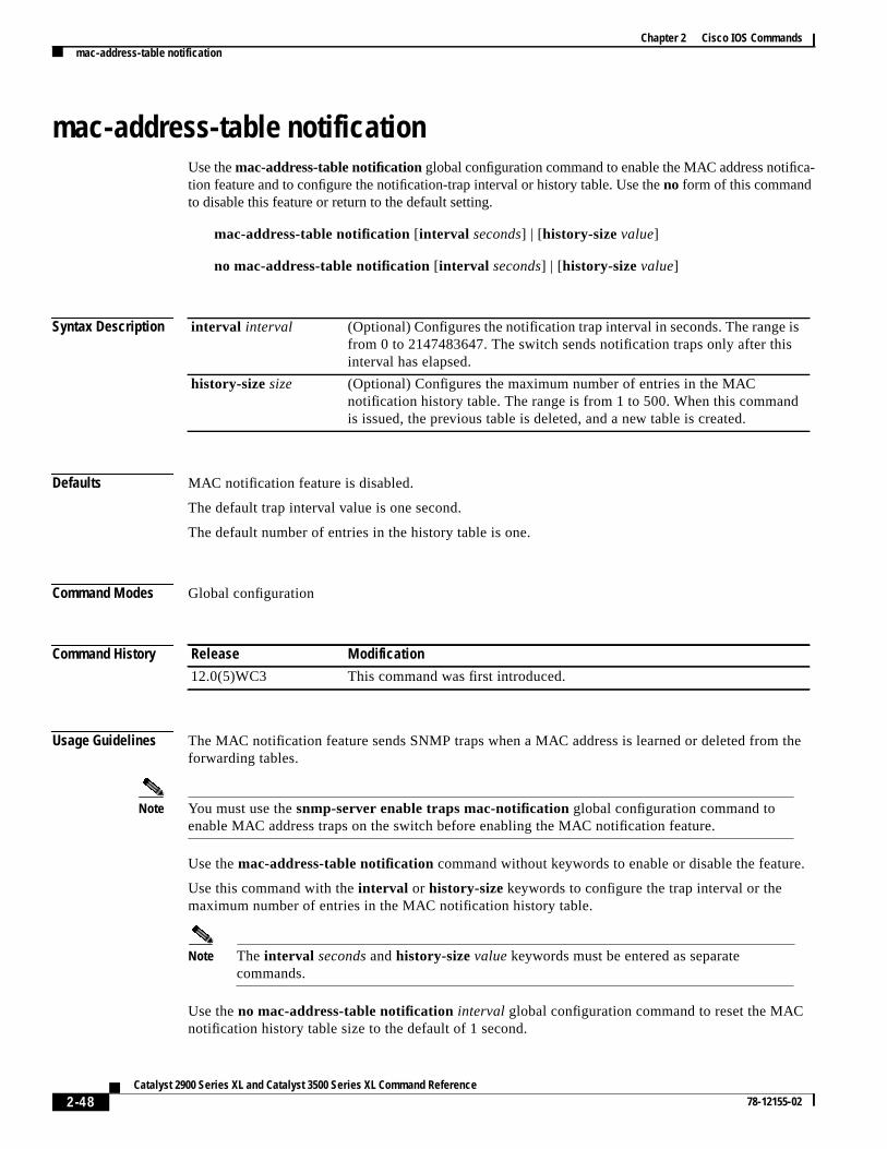
mac-address-table notificationUse themac-address-table notificationglobal configuration command to enable the MAC address notifiction feature and to configure the notification-trap interval or history table. Use theno form of this commandto disable this feature or return to the default setting.
mac-address-table notification [interval seconds] | [history-sizevalue]
no mac-address-table notification [interval seconds] | [history-sizevalue]
Syntax Description
Defaults MAC notification feature is disabled.
The default trap interval value is one second.
The default number of entries in the history table is one.
Command Modes Global configuration
Command History
Usage Guidelines The MAC notification feature sends SNMP traps when a MAC address is learned or deleted fromforwarding tables.
Note You must use thesnmp-server enable traps mac-notification global configuration command toenable MAC address traps on the switch before enabling the MAC notification feature.
Use themac-address-table notification command without keywords to enable or disable the featur
Use this command with theinterval or history-size keywords to configure the trap interval or themaximum number of entries in the MAC notification history table.
Note The interval seconds andhistory-sizevalue keywords must be entered as separatecommands.
Use theno mac-address-table notificationinterval global configuration command to reset the MACnotification history table size to the default of 1 second.
interval interval (Optional) Configures the notification trap interval in seconds. The range isfrom 0 to 2147483647. The switch sends notification traps only after thisinterval has elapsed.
history-sizesize (Optional) Configures the maximum number of entries in the MACnotification history table. The range is from 1 to 500. When this commandis issued, the previous table is deleted, and a new table is created.
Release Modification
12.0(5)WC3 This command was first introduced.
2-48Catalyst 2900 Series XL and Catalyst 3500 Series XL Command Reference
78-12155-02

Chapter 2 Cisco IOS Commandsmac-address-table notification
Use theno mac-address-table notificationhistory-sizeglobal configuration command to reset the MACnotification history table size to the default of one.
Examples This example shows how to enable the MAC notification feature:
Switch(config)# mac-address-table notification
This example shows how to set the notification trap interval to 60 seconds:
Switch(config)# mac-address-table notification interval 60
This example shows how to set the number of entries in the history table to 32:
Switch(config)# mac-address-table notification history-size 32
You can verify this command by entering theshow mac-address-table notification user EXECcommand.
Related Commands snmp-server enable traps mac-notification Enables the MAC-notification traps on a port.
show mac-address-table notification Displays MAC-notification parameters.
2-49Catalyst 2900 Series XL and Catalyst 3500 Series XL Command Reference
78-12155-02
Chapter 2 Cisco IOS Commandsmac-address-table secure
ACble.
le entryport
)
d
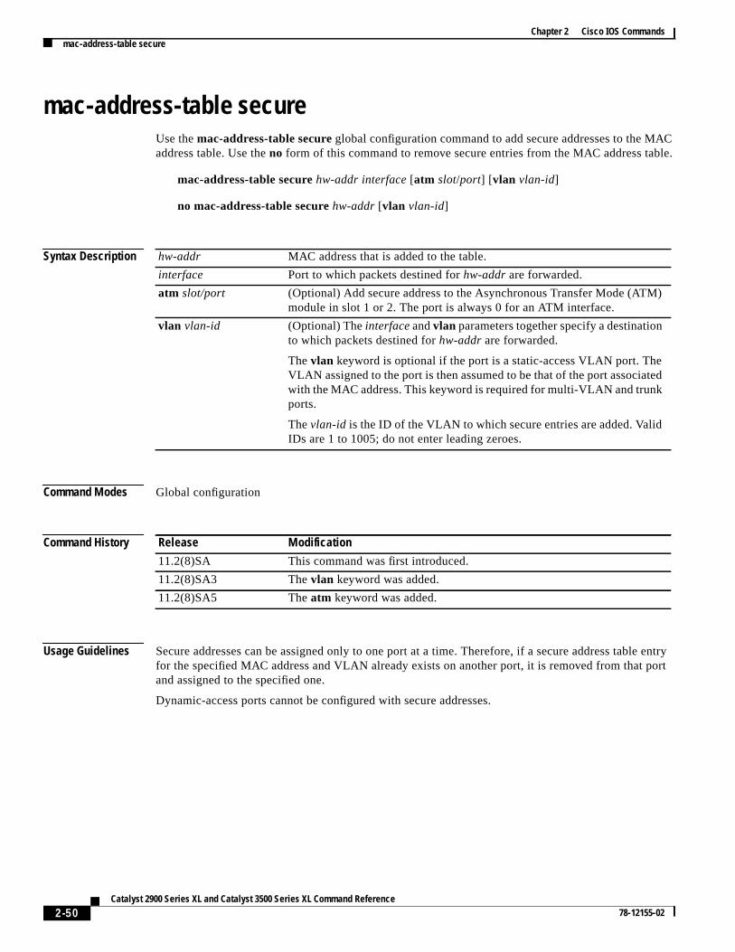
mac-address-table secureUse themac-address-table secureglobal configuration command to add secure addresses to the Maddress table. Use the no form of this command to remove secure entries from the MAC address ta
mac-address-table securehw-addr interface [atm slot/port] [vlan vlan-id]
no mac-address-table securehw-addr [vlan vlan-id]
Syntax Description
Command Modes Global configuration
Command History
Usage Guidelines Secure addresses can be assigned only to one port at a time. Therefore, if a secure address tabfor the specified MAC address and VLAN already exists on another port, it is removed from that and assigned to the specified one.
Dynamic-access ports cannot be configured with secure addresses.
hw-addr MAC address that is added to the table.
interface Port to which packets destined forhw-addr are forwarded.
atm slot/port (Optional) Add secure address to the Asynchronous Transfer Mode (ATMmodule in slot 1 or 2. The port is always 0 for an ATM interface.
vlan vlan-id (Optional) Theinterfaceandvlan parameters together specify a destinationto which packets destined forhw-addr are forwarded.
Thevlan keyword is optional if the port is a static-access VLAN port. TheVLAN assigned to the port is then assumed to be that of the port associatewith the MAC address. This keyword is required for multi-VLAN and trunkports.
Thevlan-id is the ID of the VLAN to which secure entries are added. ValidIDs are 1 to 1005; do not enter leading zeroes.
Release Modification
11.2(8)SA This command was first introduced.
11.2(8)SA3 Thevlan keyword was added.
11.2(8)SA5 Theatm keyword was added.
2-50Catalyst 2900 Series XL and Catalyst 3500 Series XL Command Reference
78-12155-02

Chapter 2 Cisco IOS Commandsmac-address-table secure
Examples This example shows how to add a secure MAC address to VLAN 6 of port fa1/1:
Switch(config)# mac-address-table secure 00c0.00a0.03fa fa1/1 vlan 6
This example shows how to add a secure MAC address to ATM port 2/1:
Switch(config)# mac-address-table secure 00c0.00a0.03fa atm 2/1
You can verify the previous command by entering theshow mac-address-table user EXEC command.
Related Commands Command Description
clear mac-address-table Deletes entries from the MAC address table.
mac-address-table aging-time Specifies the length of time that a dynamic entry remains in theMAC address table after the entry is used or updated.
mac-address-table dynamic Adds dynamic addresses to the MAC address table.
mac-address-table static Adds static addresses to the MAC address table.
show mac-address-table Displays the MAC address table.
2-51Catalyst 2900 Series XL and Catalyst 3500 Series XL Command Reference
78-12155-02

Chapter 2 Cisco IOS Commandsmac-address-table static
Cle.
he
mac-address-table staticUse themac-address-table static global configuration command to add static addresses to the MAaddress table. Use theno form of this command to remove static entries from the MAC address tab
mac-address-table statichw-addr in-port out-port-list[atm slot/port] [vlan vlan-id]
no mac-address-table statichw-addr[ in-port in-port] [out-port-list out-port-list] [vlan vlan-id]
Syntax Description
Command Modes Global configuration
Command History
hw-addr MAC address to add to the address table.
in-port Input port from which packets received with a destination address ofhw-addr are forwarded to the list of ports in theout-port-list. Thein-portmust belong to the same VLAN as all the ports in theout-port-list.
out-port-list List of ports to which packets received on ports inin-port are forwarded.All ports in the list must belong to the same VLAN.
atm slot/port (Optional) Add static addresses to Asynchronous Transfer Mode (ATM)module in slot 1 or 2. The port is always 0 for an ATM interface.
vlan vlan-id (Optional) Theinterfaceandvlan parameters together specify a destinationto which packets destined for the specified MAC address are forwarded.
Thevlan keyword is optional if all the ports specified byin-port andout-port-listare static-access VLAN ports. The VLAN assigned to the portsis assumed. This keyword is required for multi-VLAN and trunk ports.
Dynamic-access ports cannot be included in static addresses as either tsource (inport) or destination (outport).
Thevlan keyword is required on trunk ports to specify to which VLAN thestatic address is assigned.
Thevlan-id is the ID of the VLAN to which static address entries areforwarded. Valid IDs are 1 to 1005; do not enter leading zeroes.
Release Modification
11.2(8)SA This command was first introduced.
11.2(8)SA3 Thevlan keyword was added.
11.2(8)SA5 Theatm keyword was added.
2-52Catalyst 2900 Series XL and Catalyst 3500 Series XL Command Reference
78-12155-02

Chapter 2 Cisco IOS Commandsmac-address-table static
ecifys.
d
entry.
LAN
Usage Guidelines When a packet is received on the input port, it is forwarded to the VLAN of each port that you spfor theout-port-list. Different input ports can have different output-port lists for each static addresAdding a static address already defined as one modifies the port map (vlanandout-port-list) for the inputport specified.
If the variablevlan-id is omitted and theno form of the command is used, the MAC address is removefrom all VLANs.
Traffic from a static address is only accepted from a port defined in thein-port variable.
Dynamic-access ports cannot be configured as the source or destination port in a static address
Examples This example shows how to add a static address with port 1 as an input port and ports 2 and 8 of V4 as output ports:
Switch(config)# mac-address-table static c2f3.220a.12f4 fa0/1 fa0/2 fa0/8 vlan 4
You can verify the previous command by entering theshow mac-address-table user EXEC command.
Related Commands Command Description
clear mac-address-table Deletes entries from the MAC address table.
mac-address-table aging-time Specifies the length of time that a dynamic entry remains in theMAC address table after the entry is used or updated.
mac-address-table dynamic Adds dynamic addresses to the MAC address table.
mac-address-table secure Adds secure addresses to the MAC address table.
show mac-address-table Displays the MAC address table.
2-53Catalyst 2900 Series XL and Catalyst 3500 Series XL Command Reference
78-12155-02

Chapter 2 Cisco IOS Commandsmanagement
NANANAN
rom
ntby
s
utput
sameed
a
hes
.
lobalent
managementUse themanagement interface configuration command to shut down the current management VLAinterface and to enable the new management VLAN interface. The management VLAN is the VLused for managing a cluster of switches. To use this VLAN for switch management, apply this VLto a switched virtual interface or to the management interface. The default management VLAN is VL1; however, it can be changed to a new management interface on a different VLAN with valid IDs f1 to 1001.
This command also copies the current management VLAN IP information to the new managemeVLAN interface if no new IP address or network mask is provided. It also copies the cluster standgroup configuration to the new management VLAN.
management
Syntax Description This command has no arguments or keywords.
Defaults No default is defined.
Command Modes Interface configuration
Command History
Usage Guidelines No default management or no managementcommand exists to return the management VLAN to itdefault state.
The management command is not written to the configuration file, and it is not displayed in the oof theshow running-config privileged EXEC command.
Before entering themanagement command, make sure that these conditions exist:
• You must be able to move your network management station to a switch port assigned to theVLAN as the new management VLAN. (Depending on your network topology, you might not neto move your network management station: for example, you have ISL routing configured onrouter between two VLANs.)
• Connectivity through the network must exist from the network management station to all switcinvolved in the management VLAN change.
• The switch must already have a port assigned to the same VLAN as the management VLAN
Use the management command to change the management VLAN on a single switch. Use the gcluster management-vlann configuration command on the command switch to change the managemVLAN on the entire cluster.
Release Modification
12.0(5)XP This command was first introduced.
2-54Catalyst 2900 Series XL and Catalyst 3500 Series XL Command Reference
78-12155-02
Chapter 2 Cisco IOS Commandsmanagement
2 as
LAN
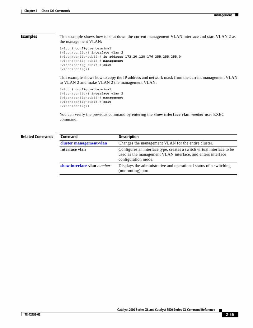
Examples This example shows how to shut down the current management VLAN interface and start VLAN the management VLAN:
Switch# configure terminalSwitch(config)# interface vlan 2Switch(config-subif)# ip address 172.20.128.176 255.255.255.0Switch(config-subif)# managementSwitch(config-subif)# exitSwitch(config)#
This example shows how to copy the IP address and network mask from the current management Vto VLAN 2 and make VLAN 2 the management VLAN:
Switch# configure terminalSwitch(config)# interface vlan 2Switch(config-subif)# managementSwitch(config-subif)# exitSwitch(config)#
You can verify the previous command by entering theshow interface vlannumberuser EXECcommand.
Related Commands Command Description
cluster management-vlan Changes the management VLAN for the entire cluster.
interface vlan Configures an interface type, creates a switch virtual interface to beused as the management VLAN interface, and enters interfaceconfiguration mode.
show interfacevlan number Displays the administrative and operational status of a switching(nonrouting) port.
2-55Catalyst 2900 Series XL and Catalyst 3500 Series XL Command Reference
78-12155-02

Chapter 2 Cisco IOS Commandsmvr (global configuration)
ion
ng a
red,
et
t
.
mvr (global configuration)Use themvr global configuration command without keywords to enable the multicast VLAN registrat(MVR) feature on the switch. Use theno form of this command to disable MVR and its options.
Use the command with keywords to set the maximum time to wait for a query reply before removiport from group membership and to specify the MVR multicast VLAN. Use theno form of thecommands to return the switch to the default settings.
mvr [group ip-address [count] [querytime value] [vlan vlan-id] ]
no mvr [group ip-address [count] [querytime value] [vlan vlan-id] ]
Syntax Description
Defaults MVR is disabled.
The switch hardware determines the maximum number of MVR entries.
No IP multicast addresses are configured on the switch.
The default count is 1.
The default query response time is 0.5 second.
The default multicast VLAN is VLAN 1.
Command Modes Global configuration
Command History
Usage Guidelines The switch hardware determines the maximum number of MVR entries.
group ip-address Statically configure an MVR group IP multicast address on the switch.
Use theno form of this command to remove a statically configured IPmulticast address or contiguous addresses or, when no IP address is enteto remove all statically configured MVR IP multicast addresses.
querytime value (Optional) Set the maximum time to wait for IGMP report memberships ona receiver port. This time only applies to receiver-port leave processing.When an IGMP query is sent from a receiver port, the switch waits for thdefault or configured MVR querytime for an IGMP group membership reporbefore removing the port from multicast group membership.
The value is the response time in units of tenths of a second. The defaulis 0.5 second.
Use theno form of the command to return to the default setting.
vlan vlan-id Specify the VLAN on which MVR multicast data is expected to be receivedThis is also the VLAN to which all the source ports belong.
Release Modification
12.0(5)XW This command was first introduced.
2-56Catalyst 2900 Series XL and Catalyst 3500 Series XL Command Reference
78-12155-02

Chapter 2 Cisco IOS Commandsmvr (global configuration)
R.h and
achedss,
after
angey
.
from
e
cond:
Use themvr group command to statically set all the IP multicast addresses that will take part in MVAny multicast data sent to a configured multicast address is sent to all the source ports on the switcto all receiver ports that have registered to receive data on that IP multicast address.
Note Themvr group command prevents adding IP multicast addresses that cause address aliasing. EIP multicast address translates to a multicast 48-bit MAC address. If the IP address being configurtranslates (aliases) to the same 48-bit MAC address as a previously configured IP multicast addrethe command fails.
Themvr querytime parameter applies only to receiver ports. You should configure the query timebefore enabling MVR and configuring the static multicast groups. You can change the query timeMVR is enabled, but you receive a warning message:
Warning: Changing MVR query response time while MVR is running.
Set the MVR multicast VLAN before the multicast addresses are configured. If it is necessary to chthe multicast VLAN, disable MVR, change the VLAN number, and then reenable MVR. Previouslconfigured groups are restored.
Examples This example shows how to enable MVR:
Switch(config)# mvr
This example shows how to disable MVR:
Switch(config)# no mvr
Use theshow mvr privileged EXEC command to display the setting for maximum multicast groups
This example shows how to configure 228.1.23.4 as an IP multicast address:
Switch(config)# mvr group 228.1.23.4
This command fails because of address aliasing:
Switch(config)# mvr group 230.1.23.4
Cannot add this IP address - aliases with previously configured IP address 228.1.23.4.
This example shows how to configure ten contiguous IP multicast groups with multicast addresses228.1.23.1 to 228.1.23.10:
Switch(config)# mvr group 228.1.23.1 10
This example shows how to delete the previously configured ten IP multicast addresses:
Switch(config)# no mvr group 228.1.23.1 10
This example shows how to delete all previously configured IP multicast addresses:
Switch(config)# no mvr group
Use the commandshow mvr members to display the IP multicast group addresses configured on thswitch.
This example shows how to set the maximum query response time as 1 second (10 tenths):
Switch(config)# mvr querytime 10
This example shows how to return the maximum query response time to the default setting of 0.5 se
2-57Catalyst 2900 Series XL and Catalyst 3500 Series XL Command Reference
78-12155-02

Chapter 2 Cisco IOS Commandsmvr (global configuration)
p.
Switch(config)# no mvr querytime
This example shows how to set VLAN 2 as the multicast VLAN:
Switch(config)# mvr vlan 2
You can verify your settings by entering the show mvr privileged EXEC command
Related Commands Command Description
mvr (interface configuration) Configures MVR source or receiver ports.
show mvr Displays MVR global parameters or port parameters.
show mvr members Displays all receiver ports that are members of an MVR multicast grou
show mvr interface Displays the configured MVR interfaces.
2-58Catalyst 2900 Series XL and Catalyst 3500 Series XL Command Reference
78-12155-02
Chapter 2 Cisco IOS Commandsmvr (interface configuration)
boundorts.
houldceivesge for
e
forle
mvr (interface configuration)Use themvr interface configuration command to configure a port as a multicast VLAN registration(MVR) receiver or source port and set the Immediate Leave feature.
Use theno form of the commands to return the port to the default settings.
mvr { type { source| receiver} | immediate}
no mvr { type { source| receiver} | immediate}
Syntax Description
Defaults A port is configured as neither receiver nor source.
The Immediate Leave feature is disabled on all ports.
No receiver port is a member of any configured multicast group.
Command Modes Interface configuration
Command History
Usage Guidelines Configure a port as a source port if that port should be able to both send and receive multicast datafor the configured multicast groups. Multicast data is received on all ports configured as source p
Configure a port as a receiver port if that port should only be able to receive multicast data and snot be able to send multicast data to the configured multicast groups. None of the receiver ports remulticast data unless it sends an Internet Group Management Protocol (IGMP) group join messaa multicast group.
Note For the Catalyst 2900 XL and Catalyst 3500 XL switches, all receiver ports must belong to the samVLAN and must not be trunk ports.
type value (Optional) Configure the port as an MVR receiver port or source port.
The default port type is neither an MVR source nor receiver port. Theno mvrtype command resets the port to the default.
source Configure the port as an uplink port that can send and receive multicast data the configured multicast groups. All source ports on a switch belong to a singmulticast VLAN.
receiver Configure the port as a subscriber port that can only receive multicast data.Receiver ports cannot belong to the multicast VLAN.
immediate Enable the Immediate Leave feature of MVR on a port. Use theno form of thiscommand to disable the feature.
Release Modification
12.0(5)XW This command was first introduced.
2-59Catalyst 2900 Series XL and Catalyst 3500 Series XL Command Reference
78-12155-02

Chapter 2 Cisco IOS Commandsmvr (interface configuration)
ort.h
isleaveIGMPrt isthe
the
tatic
iver
ertake
areN
A port that is not taking part in MVR should not be configured as an MVR receiver port or source pThis port is a normal switch port and is able to send and receive multicast data with normal switcbehavior.
The Immediate Leave feature applies only to receiver ports. When the Immediate Leave feature enabled, a receiver port leaves a multicast group more quickly. When the switch receives an IGMPmessage from a group on a receiver port, it sends out an IGMP query on that port and waits for group membership reports. If no reports are received in a configured time period, the receiver poremoved from multicast group membership. With Immediate Leave, an IGMP query is not sent fromreceiver port on which the IGMP leave was received. As soon as the leave message is received,receiver port is removed from multicast group membership, thus speeding up leave latency.
Enable the Immediate Leave feature only on receiver ports to which a single receiver device isconnected.
All receiver ports must be on the same VLAN and cannot be trunk ports. A receiver configured as a smember of a multicast group remains a member until statically removed from membership.
MVR does not support IGMP dynamic joins. You must configure static multicast addresses for receports.
The receiver VLAN is the VLAN to which the first configured receiver port belongs. If the first receivport is a dynamic port with an unassigned VLAN, it becomes an inactive receiver port and does notpart in MVR until it is assigned to the receiver VLAN. The receiver VLAN is reset whenever thereno remaining receiver ports on the switch (active or inactive), which means that the receiver VLAmight change every time the first receiver port is configured.
Examples This example shows how to configure port 0/1 as an MVR receiver port:
Switch(config)# interface FastEthernet 0/1Switch(config-if)# mvr type receiver
This example shows how to configure port 0/3 as an MVR source port:
Switch(config)# interface FastEthernet 0/3Switch(config-if)# mvr type source
This example shows how to remove port 0/1 from taking part in MVR:
Switch(config)# interface FastEthernet 0/1Switch(config-if))# no mvr
This example shows how to display configured receiver ports and source ports.:
Switch# show mvr interface
MVR PORTSPort: Fa0/1 Type: RECEIVER Status: ACTIVEPort: Fa0/2 Type: RECEIVER Status: ACTIVEPort: Fa0/3 Type: SOURCE Status: ACTIVE
This example shows how to enable Immediate Leave on Fast Ethernet port 0/1:
Switch(config)# interface FastEthernet 0/1Switch(config-if)# mvr immediate
This example shows how to disable Immediate Leave on port 0/1:
Switch(config)# interface FastEthernet 0/1Switch(config-if)# no mvr immediate
2-60Catalyst 2900 Series XL and Catalyst 3500 Series XL Command Reference
78-12155-02

Chapter 2 Cisco IOS Commandsmvr (interface configuration)
e
To display whether or not Immediate Leave is enabled on an interface, use the commandshow mvr forthe interface as in this example:
Switch# show mvr interface fastethernet 0/1Interface: Fa0/1 Immediate Leave: FALSE
Use theshow mvr members privileged EXEC command to display the multicast group address, thVLAN, and the receiver port.
Related Commands Command Description
mvr (global configuration) Enables multicast VLAN registration on the switch.
show mvr Displays MVR global parameters or port parameters.
show mvr members Displays all receiver ports that are members of an MVR multicastgroup.
show mvr interface Displays the configured MVR ports.
2-61Catalyst 2900 Series XL and Catalyst 3500 Series XL Command Reference
78-12155-02
Chapter 2 Cisco IOS Commandsntp broadcast client
rk
basis.AN
e
ntp broadcast clientUse thentp broadcast client interface configuration command to allow the system to receive NetwoTime Protocol (NTP) broadcast packets on an interface. Use theno form of the command to disable thiscapability.
ntp broadcast client
no ntp broadcast client
Syntax Description This command has no arguments or keywords.
Defaults Broadcast client mode is disabled.
Command Modes Interface configuration
Command History
Usage Guidelines Use this command to allow the system to listen to broadcast packets on an interface-by-interfaceEnter this command on the management VLAN interface. By default, the management VLAN is VL1, but you can configure a different VLAN as the management VLAN.
Examples This example shows how to synchronize the router to NTP packets that are broadcast on interfacVLAN1:
Switch(config-if)# interface vlan1Switch(config-if)# ntp broadcast client
You can verify the previous commands by entering theshow running-config privileged EXECcommand.
Related Commands
Release Modification
11.2(8)SA6 This command was first introduced.
Command Description
show running-config Displays the running configuration on the switch.
2-62Catalyst 2900 Series XL and Catalyst 3500 Series XL Command Reference
78-12155-02

Chapter 2 Cisco IOS Commandsntp broadcast destination
nated
AN
ntp broadcast destinationUse thentp broadcast destination interface configuration command to configure a Network TimeProtocol (NTP) server or peer to restrict the broadcast of NTP frames to the IP address of a desigclient or a peer. Use theno form of the command to return the setting to its default.
ntp broadcast destinationIP-address
no ntp broadcast destination
Syntax Description
Defaults No IP address or host name is assigned.
Command Modes Interface configuration
Command History
Usage Guidelines Enter this command on the management VLAN interface. By default, the management VLAN is VL1, but you can configure a different VLAN as the management VLAN.
Examples This example shows how to restrict the broadcast of NTP frames to a specific IP address:
Switch(config-if)# interface vlan1Switch(config-if)# ntp broadcast destination 172.20.128.176
Related Commands
IP-address IP address or host name of a designated client or a peer.
Release Modification
11.2(8)SA6 This command was first introduced.
Command Description
ntp broadcast client Allows the system to receive NTP broadcast packets on an interface.
2-63Catalyst 2900 Series XL and Catalyst 3500 Series XL Command Reference
78-12155-02
Chapter 2 Cisco IOS Commandsntp broadcast key
NTP
AN
e
ntp broadcast keyUse thentp broadcast key interface configuration command to configure a Network Time Protocol(NTP) server or peer to broadcast NTP frames with the authentication key that is embedded in thepacket. Use theno form of the command to return the setting to its default.
ntp broadcast keynumber
no ntp broadcast key
Syntax Description
Defaults No NTP broadcast key is defined.
Command Modes Interface configuration
Command History
Usage Guidelines Enter this command on the management VLAN interface. By default, the management VLAN is VL1, but you can configure a different VLAN as the management VLAN.
Examples This example shows how to assign an authentication key to outgoing NTP frames:
Switch(config)# interface vlan1Switch(config-if)# ntp broadcast key 1
Related Commands
number The NTP authentication key that is embedded in the NTP packet. The rangis from 0 to 4294967295.
Release Modification
11.2(8)SA6 This command was first introduced.
Command Description
ntp broadcast client Allows the system to receive NTP broadcast packets on an interface.
2-64Catalyst 2900 Series XL and Catalyst 3500 Series XL Command Reference
78-12155-02

Chapter 2 Cisco IOS Commandsntp broadcast version
nd
d
AN
ntp broadcast versionUse thentp broadcast interface configuration command to specify that a specific interface should seNetwork Time Protocol (NTP) broadcast packets. Use theno form of the command to disable thiscapability.
ntp broadcast versionnumber
no ntp broadcast
Syntax Description
Defaults Version 3 is the default.
Command Modes Interface configuration
Command History
Usage Guidelines Cisco IOS uses NTP version 3 by default. If the network (NTP server) is using NTP version 2, ansynchronization does not occur, use NTP version 2.
Enter this command on the management VLAN interface. By default, the management VLAN is VL1, but you can configure a different VLAN as the management VLAN.
Examples This example shows how to configure interface VLAN 1 to send NTP version 2 packets:
Switch(config-if)# interface vlan1Switch(config-if)# ntp broadcast version 2
You can verify the previous commands by entering theshow running-config privileged EXECcommand.
Related Commands
number The range is 1 to 3.
Release Modification
11.2(8)SA6 This command was first introduced.
Command Description
ntp broadcast client Allows the system to receive NTP broadcast packets on an interface.
show running-config Displays the running configuration on the switch.
2-65Catalyst 2900 Series XL and Catalyst 3500 Series XL Command Reference
78-12155-02
Chapter 2 Cisco IOS Commandsntp max-associations
rk
NTP.
ntp max-associationsUse thentp max-associations global configuration command to set the maximum number of NetwoTime Protocol (NTP) associations that are allowed on a server. Use theno form of this command todisable this feature.
ntp max-associations[number]
no ntp max-associations
Syntax Description
Defaults The number of NTP associations is 100.
Command Modes Global configuration
Command History
Usage Guidelines This command can control the number of peers that can use the switch to synchronize to it through
After you enable a switch as an NTP server, use this command to set the maximum number ofassociations that are allowed on a server.
Examples This example shows how to set the maximum number of NTP associations to 44:
Switch(config)# ntp max-associations 44
You can verify the previous command by entering theshow running-configprivileged EXEC command.
Related Commands
number (Optional) Specify the number of NTP associations. The range is from 0to 4294967295.
Release Modification
11.2(8)SA6 This command was first introduced.
Command Description
show running-config Displays the running configuration on the switch.
2-66Catalyst 2900 Series XL and Catalyst 3500 Series XL Command Reference
78-12155-02

Chapter 2 Cisco IOS Commandsntp source
ime
ddressot be
dress
ntp sourceUse thentp source global configuration command to use a particular source address in Network TProtocol (NTP) packets. Use theno form of this command to remove the specified source address.
ntp source interface
no ntp source
Syntax Description
Defaults No source address is defined.
Command Modes Global configuration
Command History
Usage Guidelines Use this command when you want to use a particular source IP address for all NTP packets. The ais taken from the specified interface. This command is useful if the address on an interface cannused as the destination for reply packets. If thesourcekeyword is present on anntp server or ntp peercommand, that value overrides the global value.
Examples This example shows how to configure the switch to use the IP address of VLAN1 as the source adof all outgoing NTP packets:
Switch(config)# ntp source vlan1
You can verify the previous command by entering theshow running-configprivileged EXEC command.
Related Commands
interface Any valid system interface name.
Release Modification
11.2(8)SA6 This command was first introduced.
Command Description
ntp source Allows the switch system clock to be synchronized by a time server.
show running-config Displays the running configuration on the switch.
2-67Catalyst 2900 Series XL and Catalyst 3500 Series XL Command Reference
78-12155-02
Chapter 2 Cisco IOS Commandsport block
.
port blockUse theport block interface configuration command to block the flooding of unknown unicast ormulticast packets to a port. Use theno form of this command to resume normal forwarding.
port block { unicast | multicast}
no port block { unicast | multicast}
Syntax Description
Defaults Flood unknown unicast and multicast packets to all ports.
Command Modes Interface configuration
Command History
Usage Guidelines Theport block command cannot be entered for a network port.
If a trunk port is not a network port, theunicast keyword applies. Themulticast keyword is supportedon trunk ports. Both port block features affect all the VLANs associated with the trunk port.
Examples This example shows how to block the forwarding of multicast and unicast packets to a port:
Switch(config-if)# port block unicastSwitch(config-if)# port block multicast
You can verify the previous commands by entering theshow port block user EXEC command.
Related Commands
unicast Packets with unknown unicast addresses are not forwarded to this port.
multicast Packets with unknown multicast addresses are not forwarded to this port
Release Modification
11.2(8)SA This command was first introduced.
Command Description
show port block Displays the blocking of unicast or multicast flooding to a port.
2-68Catalyst 2900 Series XL and Catalyst 3500 Series XL Command Reference
78-12155-02

Chapter 2 Cisco IOS Commandsport group
abit canp. Use
.
-based
t mixre port
port groupUse theport group interface configuration command to assign a port to a Fast EtherChannel or GigEtherChannel port group. Up to 12 port groups can be created on a switch. Any number of portsbelong to a destination-based port group. Up to eight ports can belong to a source-based port groutheno form of this command to remove a port from a port group.
port group group-number[distribution {source | destination}]
no port group
Syntax Description
Defaults Port does not belong to a port group.
The default forwarding method is source.
Command Modes Interface configuration
Command History
Usage Guidelines An Asynchronous Transfer Mode (ATM) port is the only port thatcannotbelong to a port group. For allother ports, these restrictions apply:
• Do not group Fast Ethernet and Gigabit ports together.
• No port group member can be configured for Switched Port Analyzer (SPAN) port monitoring
• No port group member can be enabled for port security.
• You can create up to 12 port groups. You can have source-based port groups and destinationsource groups. A source-based port group can have up to eight ports in its group. Adestination-based port group can contain an unlimited number of ports in its group. You cannosource-based and destination-based ports in the same group. You can independently configugroups that link switches, but you must consistently configure both ends of a port group.
group-number Port group number to which the port belongs. The range isfrom 1 to 12.
distribution { source | destination} (Optional) Forwarding method for the port group.
• source—Set the port to forward traffic to a port groupbased on the packet source address. This is the defaultforwarding method.
• destination—Set the port to forward traffic to a portgroup based on the packet destination address.
Release Modification
11.2(8)SA3 This command was first introduced.
2-69Catalyst 2900 Series XL and Catalyst 3500 Series XL Command Reference
78-12155-02

Chapter 2 Cisco IOS Commandsport group
ll
ccess
l ports:
other
sed
ing:
• Port group members must belong to the same set of VLANs and must be all static-access, amulti-VLAN, or all trunk ports.
• Dynamic-access ports cannot be grouped with any other port, not even with other dynamic-aports.
When a group is first formed, the switch automatically sets these parameters to be the same on al
• VLAN membership of ports in the group
• VLAN mode (static, multi, trunk) of ports in the group
• Encapsulation method of the trunk
• Native VLAN configuration if the trunk uses IEEE 802.1Q
• Allowed VLAN list configuration of the trunk port
• Spanning Tree Protocol (STP) Port Fast option
• STP port priority
• STP path cost
• Network port configuration for source-based port group
• Protected port
Configuration of the first port added to the group is used when setting the above parameters for ports in the group. After a group is formed, changing any parameter in the above list changes theparameter on all other ports.
Use thedistribution keyword to customize the port group to your particular environment. Theforwarding method you choose depends on how your network is configured. However, source-baforwarding works best for most network configurations.
This command is not supported on the ATM modules.
Examples This example shows how to add a port to a port group by using the default source-based forward
Switch(config-if)# port group 1
This example shows how to add a port to a group by using destination-based forwarding:
Switch(config-if)# port group 2 distribution destination
You can verify the previous commands by entering theshow port group user EXEC command.
Related Commands Command Description
show port group Displays the ports that belong to a port group.
2-70Catalyst 2900 Series XL and Catalyst 3500 Series XL Command Reference
78-12155-02

Chapter 2 Cisco IOS Commandsport monitor
rt
ss
ity:
hip
rt cand
.
port monitorUse theport monitor interface configuration command to enable Switch Port Analyzer (SPAN) pomonitoring on a port. Use theno form of this command to return the port to its default value.
port monitor [ interface |vlan vlan-id]
no port monitor [ interface |vlan vlan-id]
Syntax Description
Defaults Port does not monitor any other ports.
Command Modes Interface configuration
Command History
Usage Guidelines Enabling port monitoring without specifying a port causes all other ports in the same VLAN to bemonitored.
Entering theport monitor vlan 1 command causes monitoring of all traffic to and from the IP addreconfigured on VLAN 1.
Asynchronous Transfer Mode (ATM) ports are the only ports thatcannotbe monitor ports. However, youcan monitor ATM ports. The following restrictions apply for ports that have port-monitoring capabil
• A monitor port cannot be in a Fast EtherChannel or Gigabit EtherChannel port group.
• A monitor port cannot be enabled for port security.
• A monitor port cannot be a multi-VLAN port.
• A monitor port must be a member of the same VLAN as the port monitored. VLAN memberschanges are not allowed on monitor ports and ports being monitored.
• A monitor port cannot be a dynamic-access port or a trunk port. However, a static-access pomonitor a VLAN on a trunk, a multi-VLAN port, or a dynamic-access port. The VLAN monitoreis the one associated with the static-access port.
• Port monitoring does not work if both the monitor and monitored ports are protected ports.
interface (Optional) Module type, slot, and port number for the SPAN to be enabledThe interface specified is the port to be monitored.
vlan vlan-id (Optional) ID of the VLAN to be monitored.
Note VLAN 1 is the only valid option.
Release Modification
11.2(8)SA This command was first introduced.
11.2(8)SA3 Thevlan keyword was added.
2-71Catalyst 2900 Series XL and Catalyst 3500 Series XL Command Reference
78-12155-02

Chapter 2 Cisco IOS Commandsport monitor
Examples This example shows how to enable port monitoring on port fa0/2:
Switch(config-if)# port monitor fa0/2
You can verify the previous command by entering theshow port monitor user EXEC command.
Related Commands Command Description
show port monitor Displays the ports for which SPAN port monitoring is enabled.
2-72Catalyst 2900 Series XL and Catalyst 3500 Series XL Command Reference
78-12155-02
Chapter 2 Cisco IOS Commandsport network
Alle
othith
cted,r port
port networkUse theport network interface configuration command to define a port as the switch network port.traffic with unknown unicast addresses is forwarded to the network port on the same VLAN. Use thnoform of this command to return the port to the default value.
port network
no port network
Syntax Description This command has no arguments or keywords.
Defaults No network port is defined.
Command Modes Interface configuration
Command History
Usage Guidelines The following restrictions apply to network ports:
• A network port can be a static-access port, a multi-VLAN port, a port group, or a trunk port. Bthe multi-VLAN port and the trunk port become the network port for all the VLANs associated wthat port.
• A network port cannot be an Asynchronous Transfer Mode (ATM), a secure, a monitor, a proteor a dynamic-access port. You can assign a dynamic-access port to a VLAN in which anotheis the network port.
• Each VLAN can have one network port.
• A network port cannot be in a destination-based port group.
• A network port cannot be on an ATM module.
• A network port cannot be a protected port.
Examples This example shows how to set a port as a network port:
Switch(config-if)# port network
You can verify the previous command by entering theshow port network privileged EXEC command.
Related Commands
Release Modification
11.2(8)SA4 This command was first introduced.
Command Description
show port network Displays the network port defined for the switch or VLAN.
2-73Catalyst 2900 Series XL and Catalyst 3500 Series XL Command Reference
78-12155-02
Chapter 2 Cisco IOS Commandsport protected
st
port.
from
samerts on
port protectedUse theport protected interface configuration command to isolate unicast, multicast, and broadcatraffic at Layer 2 from other protected ports on the same switch. Use theno form of the command todisable the protected port.
port protected
no port protected
Syntax Description This command has no keywords or arguments.
Defaults No protected port is defined.
A protected port does not forward any unicast, multicast, or broadcast traffic to any other protected
A protected port continues to forward and receive unicast, multicast, and broadcast traffic to andunprotected ports.
Command Modes Interface configuration
Command History
Usage Guidelines The port protection feature is local to the switch; communication between protected ports on theswitch is possible only through a Layer 3 device. To prevent communication between protected podifferent switches, you must configure the protected ports for unique VLANs on each switch andconfigure a trunk link between the switches.
A protected port cannot be a network port.
Port monitoring does not work if both the monitor and monitored ports are protected ports.
A protected port is different from a secure port.
Release Modification
12.0(5)XU This command was first introduced.
2-74Catalyst 2900 Series XL and Catalyst 3500 Series XL Command Reference
78-12155-02

Chapter 2 Cisco IOS Commandsport protected
Examples This example shows how to enable a protected port on interface fa0/3:
Switch(config)# interface fa0/3Switch(config-if)# port protected
You can verify the previous command by enteringthe show port protected user EXEC command.
Related Commands Command Description
show port protected Displays the ports that are in port-protected mode.
2-75Catalyst 2900 Series XL and Catalyst 3500 Series XL Command Reference
78-12155-02

Chapter 2 Cisco IOS Commandsport security
the
port securityUse theport security interface configuration command to enable port security on a port and restrictuse of the port to a user-defined group of stations. Use theno form of this command to return the portto its default value.
port security [action {shutdown | trap } | max-mac-countaddresses]
no port security
Syntax Description
Defaults Port security is disabled.
When enabled, the default action is to generate an SNMP trap.
Command Modes Interface configuration
Command History
Usage Guidelines If you specifytrap , use thesnmp-server hostglobal configuration command to configure the SNMPtrap host to receive traps.
The following restrictions apply to secure ports:
• A secure port cannot belong to a Fast EtherChannel or Gigabit EtherChannel port group.
• A secure port cannot have Switched Port Analyzer (SPAN) port monitoring enabled on it.
• A secure port cannot be a multi-VLAN port.
• A secure port cannot be a network port.
• A secure port cannot be an Asynchronous Transfer Mode (ATM) port.
• A secure port cannot be a dynamic-access port or a trunk port.
action { shutdown | trap } (Optional) Action to take when an address violation occurs on thisport.
• shutdown—Disable the port when a security violation occurs.
• trap—Generate a Simple Network Management Protocol(SNMP) trap when a security violation occurs.
max-mac-countaddresses (Optional) The maximum number of secure addresses that this portcan support. The range is from 1 to 132.
Release Modification
11.2(8)SA This command was first introduced.
2-76Catalyst 2900 Series XL and Catalyst 3500 Series XL Command Reference
78-12155-02

Chapter 2 Cisco IOS Commandsport security
ress
Examples This example shows how to enable port security and what action the port takes in case of an addviolation (shutdown).Switch(config-if)# port security action shutdown
This example shows how to set the maximum number of addresses that the port can learn to 8.
Switch(config-if)# port security max-mac-count 8
You can verify the previous commands by entering theshow port security privileged EXEC command.
Related Commands Command Description
show port security Displays the port security settings defined for the port.
2-77Catalyst 2900 Series XL and Catalyst 3500 Series XL Command Reference
78-12155-02

Chapter 2 Cisco IOS Commandsport storm-control
ast
nd 5000
, and
port storm-controlUse theport storm-control interface configuration command to enable broadcast, multicast, or unicstorm control on a port. Use theno form of this command to disable storm control or one of thestorm-control parameters on the port.
port storm-control { broadcast | multicast | unicast} {{ action { filter | shutdown} | threshold{ rising rising-numberfalling falling-number} | trap }}
no port storm-control { broadcast | multicast | unicast}
Syntax Description
Defaults Broadcast, multicast, and unicast storm control are disabled.
The rising thresholds are 500 broadcast packets per second, 2500 multicast packets per second, aunicast packets per second.
The falling thresholds are 250 broadcast packets per second, 1200 multicast packets per second2500 unicast packets per second.
Command Modes Interface configuration
{ broadcast | multicast | unicast} Determine the type of packet-storm suppression.
• broadcast—Enable broadcast storm control on the port.
• multicast—Enable multicast storm control on the port.
• unicast—Enable unicast storm control on the port.
{ action { filter | shutdown} (Optional) Determine the type of action to perform.
• filter —Filter traffic during a storm.
• shutdown—Disable the port during a storm.
threshold { rising rising-numberfalling falling-number}
Defines the rising and falling thresholds.
• rising rising-number—Block the flooding of storm packetswhen the value specified forrising-number is reached. Therising-number is 0 to 4294967295 packets per second.
• falling falling-number—Restart the normal transmission ofbroadcast packets when the value specified forfalling-number is reached. Thefalling-number is 0to 4294967295 packets per second.
trap (Optional) Generate a Simple Network Management Protocol(SNMP) trap when the traffic on the port crosses the rising orfalling threshold. Traps are generated only for broadcast trafficand not for unicast or multicast traffic.
2-78Catalyst 2900 Series XL and Catalyst 3500 Series XL Command Reference
78-12155-02
Chapter 2 Cisco IOS Commandsport storm-control
ion iswhen
Command History
Usage Guidelines Do not set the rising and falling thresholds to the same value.
Examples This example shows how to enable broadcast storm control on a port. In this example, transmissinhibited when the number of broadcast packets arriving on the port reaches 1000 and is restartedthe number drops to 200.
Switch(config-if)# port storm-control broadcast threshold rising 1000 falling 200
You can verify the previous command by entering theshow port storm-control user EXEC command.
Related Commands
Release Modification
11.2(8)SA This command was first introduced.
12.0(5)XU Themulticast, unicast, action, andshutdown keywords were added.
Command Description
show port storm-control Displays the packet storm-control information.
2-79Catalyst 2900 Series XL and Catalyst 3500 Series XL Command Reference
78-12155-02
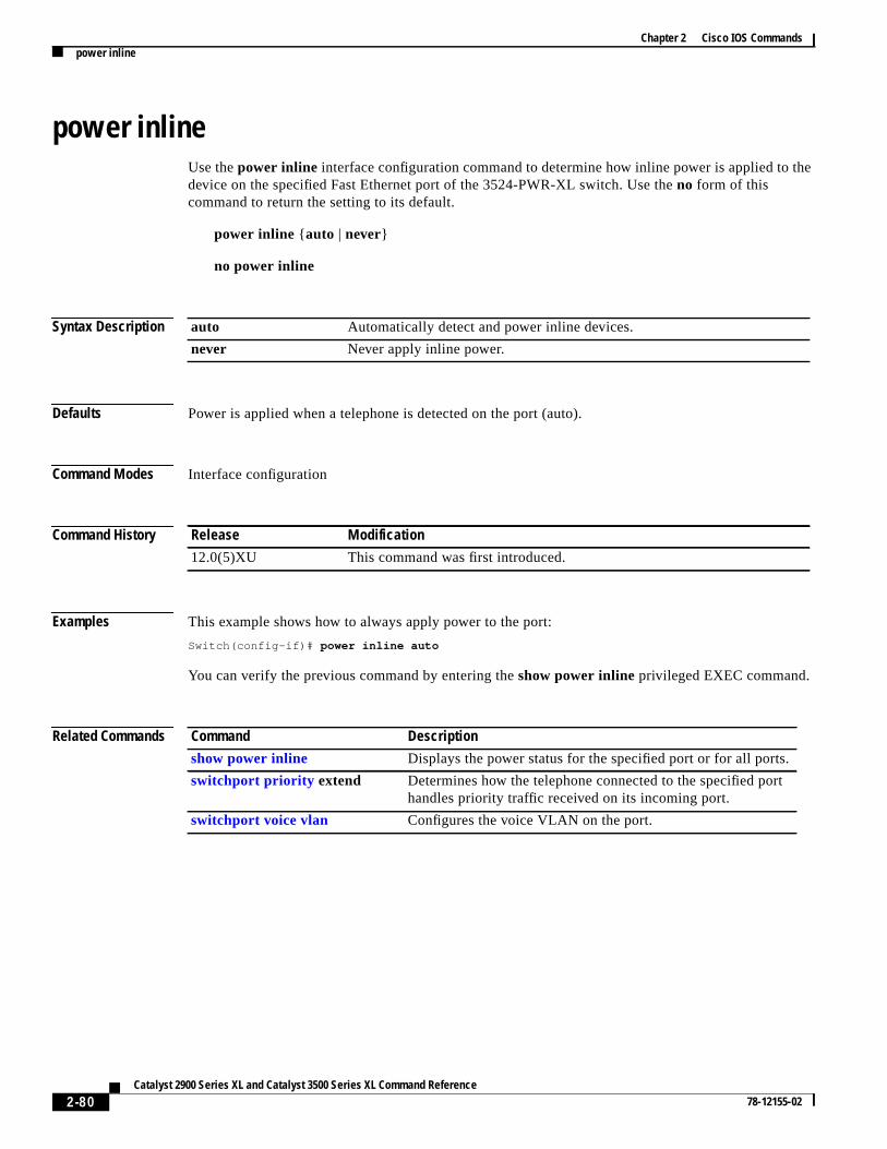
Chapter 2 Cisco IOS Commandspower inline
he
power inlineUse thepower inline interface configuration command to determine how inline power is applied to tdevice on the specified Fast Ethernet port of the 3524-PWR-XL switch. Use theno form of thiscommand to return the setting to its default.
power inline { auto | never}
no power inline
Syntax Description
Defaults Power is applied when a telephone is detected on the port (auto).
Command Modes Interface configuration
Command History
Examples This example shows how to always apply power to the port:
Switch(config-if)# power inline auto
You can verify the previous command by entering theshow power inlineprivileged EXEC command.
Related Commands
auto Automatically detect and power inline devices.
never Never apply inline power.
Release Modification
12.0(5)XU This command was first introduced.
Command Description
show power inline Displays the power status for the specified port or for all ports.
switchport priority extend Determines how the telephone connected to the specified porthandles priority traffic received on its incoming port.
switchport voice vlan Configures the voice VLAN on the port.
2-80Catalyst 2900 Series XL and Catalyst 3500 Series XL Command Reference
78-12155-02

Chapter 2 Cisco IOS Commandsrcommand
mber
s.
cess a
witchf youat users the
ion15. If tog
lege
15.
n
tions.
e
0
rcommandUse thercommand user EXEC command to start a Telnet session and to enter commands on a meswitch from the command switch. To end the session, enter theexit command.
rcommand { n | commander | mac-addresshw-addr}
Syntax Description
Command Modes User EXEC
Command History
Usage Guidelines If the switch is the command switch but the member switchn does not exist, an error message appearTo obtain the switch number, enter theshow cluster members privileged EXEC command from thecommand switch.
You can use this command to access a member switch from the command-switch prompt or to accommand switch from the member-switch prompt.
For Catalyst 2900 XL and Catalyst 3500 XL switches, the Telnet session accesses the member-scommand-line interface (CLI) at the same privilege level as on the command switch. For example, ienter this command at user level on the cluster command switch, the member switch is accessedlevel. If you use this command on the command switch at privileged level, the command accesseremote device at privileged level. If you use an intermediate enable-level lower thanprivileged, accessto the member switch is at user level.
For Catalyst 1900 and Catalyst 2820 switches running standard edition software, the Telnet sessaccesses the menu console (the menu-driven interface) if the command switch is at privilege levelthe command switch is at privilege level 1, you are prompted for the password before being ableaccess the menu console. Command switch privilege levels map to the member switches runninstandard edition software as follows:
• If the command switch privilege level is from 1 to 14, the member switch is accessed at privilevel 1.
• If the command switch privilege level is 15, the member switch is accessed at privilege level
The Catalyst 1900 and Catalyst 2820 CLI is available only on switches running Enterprise EditioSoftware.
This command does not work if the vty lines of the command switch have access-class configura
You are not prompted for a password because the member switches inherited the password of thcommand switch when they joined the cluster.
n Provide the number that identifies a cluster member. The range is fromto 15.
commander Provide access to the command switch from a member switch.
mac-addresshw-addr MAC address of the member switch.
Release Modification
11.2(8)SA6 This command was first introduced.
2-81Catalyst 2900 Series XL and Catalyst 3500 Series XL Command Reference
78-12155-02

Chapter 2 Cisco IOS Commandsrcommand
ed to
Examples This example shows how to start a session with member 3. All subsequent commands are directmember 3 until you enter theexit command or close the session.Switch> rcommand 3Switch-3> show versionCisco Internet Operating System Software ......Switch-3> exitSwitch>
Related Commands Command Description
show cluster members Displays information about the cluster members.
2-82Catalyst 2900 Series XL and Catalyst 3500 Series XL Command Reference
78-12155-02

Chapter 2 Cisco IOS Commandsreset
inVLAN
tabase:
d
,
resetUse thereset VLAN database command to abandon the proposed VLAN database and to remain VLAN database mode. This command resets the proposed database to the currently implementeddatabase on the switch.
reset
Syntax Description This command has no arguments or keywords.
Defaults No default is defined.
Command Modes VLAN database
Command History
Examples This example shows how to abandon the proposed VLAN database and to reset to the VLAN da
Switch(vlan)# resetSwitch(vlan)#
You can verify the previous command by entering theshow changesandshow proposed VLANdatabase commands.
Related Commands
Release Modification
11.2(8)SA4 This command was first introduced.
Command Description
abort Abandons the proposed VLAN database, exits VLAN database mode, anreturns to privileged EXEC mode.
apply Implements the proposed VLAN database, increments the databaseconfiguration revision number, propagates it throughout the administrativedomain, and remains in VLAN database mode.
exit Implements the proposed VLAN database, increments the databaseconfiguration number, propagates it throughout the administrative domainand returns to privileged EXEC mode.
show changes Displays the differences between the VLAN database currently on theswitch and the proposed VLAN database.
show proposed Displays the proposed VLAN database or a selected VLAN from it.
shutdown vlan Shuts down (suspends) local traffic on the specified VLAN.
vlan database Enters VLAN database mode from the command-line interface (CLI).
2-83Catalyst 2900 Series XL and Catalyst 3500 Series XL Command Reference
78-12155-02

Chapter 2 Cisco IOS Commandsrmon collection stats
he error
or
rmon collection statsUse thermon collection statsinterface configuration command to collect Ethernet group statistics. TEthernet group statistics include utilization statistics about broadcast and multicast packets, andstatistics about Cyclic Redundancy Check (CRC) alignment errors and collisions. Use theno form ofthis command to return to the default setting.
rmon collection statsindex[owner name]
no rmon collection statsindex[owner name]
Syntax Description
Defaults The RMON statistics collection is disabled.
Command Modes Interface configuration
Command History
Usage Guidelines The RMON statistics collection command is based on hardware counters.
Examples This example shows how to collect RMON statistics for the owner root on interface fa01:
Switch(config)# interface fa0/1Switch(config-if)# rmon collection stats 2 owner root
You can verify this command by entering theshow rmon statisticscommand in user EXEC mode.
Related Commands
index Remote Network Monitoring (RMON) collection control index. The range isfrom 1 to 65535.
owner name (Optional) Owner of the RMON collection.
Release Modification
12.0(5)WC1 This command was first introduced.
Command Description
show rmon statistics Displays RMON statistics.
Refer to the Cisco IOS Release 12.0 documentation on Cisco.com finformation about this command.
2-84Catalyst 2900 Series XL and Catalyst 3500 Series XL Command Reference
78-12155-02
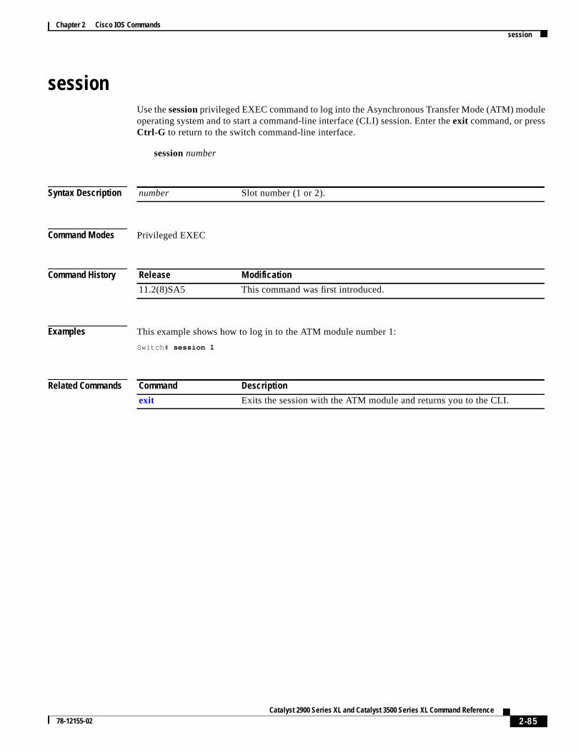
Chapter 2 Cisco IOS Commandssession
le
sessionUse thesessionprivileged EXEC command to log into the Asynchronous Transfer Mode (ATM) moduoperating system and to start a command-line interface (CLI) session. Enter theexit command, or pressCtrl-G to return to the switch command-line interface.
sessionnumber
Syntax Description
Command Modes Privileged EXEC
Command History
Examples This example shows how to log in to the ATM module number 1:
Switch# session 1
Related Commands
number Slot number (1 or 2).
Release Modification
11.2(8)SA5 This command was first introduced.
Command Description
exit Exits the session with the ATM module and returns you to the CLI.
2-85Catalyst 2900 Series XL and Catalyst 3500 Series XL Command Reference
78-12155-02

Chapter 2 Cisco IOS Commandsshow cgmp
ocol
GMP
show cgmpUse theshow cgmpuser EXEC command to display the state of the Cisco Group Management Prot(CGMP)-learned multicast groups and routers.
show cgmp[state | holdtime | [vlan vlan-id] | [group [address] | router [address]]]
Syntax Description
Command Modes User EXEC
Command History
Usage Guidelines This command displays CGMP information about known routers and groups, as well as whether Cis enabled, whether Fast Leave is enabled, and the value of the router timeout. Ifshow cgmpis enteredwith no arguments, all information appears.
state (Optional) Display whether CGMP is enabled or not, whether Fast Leave isenabled or not, and the router port timeout value.
holdtime (Optional) Display the router port timeout value in seconds.
vlan vlan-id (Optional) Limit the display to the specified VLAN. Valid IDs are from 1 to1001; do not enter leading zeroes.
group address (Optional) Display all known multicast groups and the destination ports.Limited to given VLAN if vlan keyword is entered; limited to a specific groupif the addressvariable is entered. Theaddressis the MAC address of the group.
router address (Optional) Display all routers, their ports, and expiration times. Limited to agiven VLAN if the vlan keyword entered; limited to a specific router if theaddress variable is entered. Theaddressis the MAC address of the router.
Release Modification
11.2(8)SA3 This command was first introduced.
2-86Catalyst 2900 Series XL and Catalyst 3500 Series XL Command Reference
78-12155-02

Chapter 2 Cisco IOS Commandsshow cgmp
d
Examples This is an example of output from theshow cgmp command.
Switch> show cgmp
CGMP is running.CGMP Fast Leave is not running.CGMP Allow reserved address to join GDA.Default router timeout is 300 sec.
vLAN IGMP MAC Address Interfaces------ ----------------- ----------- 1 0100.5e01.0203 Fa0/8 1 0100.5e00.0128 Fa0/8
vLAN IGMP Router Expire Interface------ ----------------- -------- ---------- 1 0060.5cf3.d1b3 197 sec Fa0/8
Related Commands Command Description
cgmp Enables CGMP. Also enables and disables the Fast Leave parameter ansets the router port aging time.
clear cgmp Deletes information that was learned by the switch by using CGMP.
2-87Catalyst 2900 Series XL and Catalyst 3500 Series XL Command Reference
78-12155-02

Chapter 2 Cisco IOS Commandsshow changes
asee two
e
t
show changesUse theshow changesVLAN database command to display the differences between the VLAN databon the switch and the proposed VLAN database. You can also display the differences between thfor a selected VLAN.
show changes[vlan-id]
Syntax Description
Command Modes VLAN database
Command History
Examples This is an example of output from theshow changescommand. It displays the differences between thcurrent and proposed databases.
Switch(vlan)# show changes
DELETED: VLAN ISL Id: 4 Name: VLAN0004 Media Type: Ethernet VLAN 802.10 Id: 100004 State: Operational MTU: 1500
DELETED: VLAN ISL Id: 6 Name: VLAN0006 Media Type: Ethernet VLAN 802.10 Id: 100006 State: Operational MTU: 1500
MODIFIED: VLAN ISL Id: 7 Current State: Operational Modified State: Suspended
vlan-id (Optional) ID of the VLAN in the current or proposed database. If this variable isomitted, all the differences between the two VLAN databases are displayed,including the pruning state and Version 2 mode. Valid IDs are from 1 to 1005; do noenter leading zeroes.
Release Modification
11.2(8)SA4 This command was first introduced.
2-88Catalyst 2900 Series XL and Catalyst 3500 Series XL Command Reference
78-12155-02

Chapter 2 Cisco IOS Commandsshow changes
This is an example of output from theshow changes 7command. It displays the differences betweenVLAN 7 in the current and proposed database.
Switch(vlan)# show changes 7
MODIFIED: VLAN ISL Id: 7 Current State: Operational Modified State: Suspended
Related Commands Command Description
show current Displays the VLAN database on the switch or a selected VLAN from it.
show proposed Displays the proposed VLAN database or a selected VLAN from it.
2-89Catalyst 2900 Series XL and Catalyst 3500 Series XL Command Reference
78-12155-02

Chapter 2 Cisco IOS Commandsshow cluster
r to
at the
ber
alsoisplays
show clusterUse theshow clusteruser EXEC command to display the cluster status and a summary of the clustewhich the switch belongs. This command can be entered on command and member switches.
show cluster
Syntax Description This command has no arguments or keywords.
Command Modes User EXEC
Command History
Usage Guidelines If the switch is not a command switch or a member switch, the command displays an empty line prompt.
On a member switch, this command displays the identity of the command switch, the switch memnumber, and the state of its connectivity with the command switch.
On a command switch, this command displays the cluster name and the number of members. It shows the cluster status and length of time since the status changed. If redundancy is enabled, it dthe primary and secondary command-switch information.
If you enter this command on a switch that is not a cluster member, the error messageNot a management
cluster member appears.
Examples This is an example of output when this command is entered on the active command switch:
Switch> show clusterCommand switch for cluster "Ajang" Total number of members: 7 Status: 1 members are unreachable Time since last status change: 0 days, 0 hours, 2 minutes Redundancy: Enabled Standby command switch: Member 1 Standby Group: Ajang_standby Standby Group Number: 110 Heartbeat interval: 8 Heartbeat hold-time: 80 Extended discovery hop count: 3
This is an example of output when this command is entered on a member switch:
Switch1> show clusterMember switch for cluster "mcluster" Member number: 3 Management IP address: 192.192.192.192 Command switch mac address: 0000.0c07.ac14 Heartbeat interval: 8 Heartbeat hold-time: 80
Release Modification
11.2(8)SA6 This command was first introduced.
2-90Catalyst 2900 Series XL and Catalyst 3500 Series XL Command Reference
78-12155-02

Chapter 2 Cisco IOS Commandsshow cluster
as the
rated
from
,it.
This is an example of output when this command is entered on a member switch that is configuredstandby command switch:
Switch> show clusterMember switch for cluster "mcluster" Member number: 3 (Standby command switch) Management IP address: 192.192.192.192 Command switch mac address: 0000.0c07.ac14 Heartbeat interval: 8 Heartbeat hold-time: 80
This is an example of output when this command is entered on the command switch that is sepafrom member 1:
3524-24> show clusterCommand switch for cluster "Ajang" Total number of members: 7 Status: 1 members are unreachable Time since last status change: 0 days, 0 hours, 5 minutes Redundancy: Disabled Heartbeat interval: 8 Heartbeat hold-time: 80 Extended discovery hop count: 3
This is an example of output when this command is entered on a member switch that is separatedthe command switch:
3512-12> show clusterMember switch for cluster "mcluster" Member number: <UNKNOWN> Management IP address: 192.192.192.192 Command switch mac address: 0000.0c07.ac14 Heartbeat interval: 8 Heartbeat hold-time: 80
Related Commands Command Description
cluster enable Enables a command-capable switch as the cluster command switchassigns a cluster name, and optionally assigns a member number to
show cluster candidates Displays a list of candidate switches.
show cluster members Displays information about the cluster members.
2-91Catalyst 2900 Series XL and Catalyst 3500 Series XL Command Reference
78-12155-02
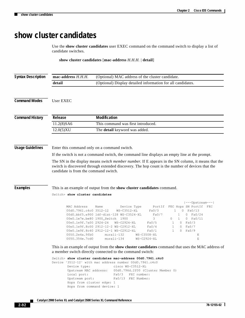
Chapter 2 Cisco IOS Commandsshow cluster candidates
ee
f
show cluster candidatesUse theshow cluster candidates user EXEC command on the command switch to display a list ofcandidate switches.
show cluster candidates[mac-addressH.H.H. | detail]
Syntax Description
Command Modes User EXEC
Command History
Usage Guidelines Enter this command only on a command switch.
If the switch is not a command switch, the command line displays an empty line at the prompt.
The SN in the display meansswitch member number. If E appears in the SN column, it means that thswitch is discovered through extended discovery. The hop count is the number of devices that thcandidate is from the command switch.
Examples This is an example of output from theshow cluster candidates command.
Switch> show cluster candidates
|---Upstream---|MAC Address Name Device Type PortIf FEC Hops SN PortIf FEC00d0.7961.c4c0 3512-12 WS-C3512-XL Fa0/3 1 0 Fa0/1300d0.bbf5.e900 ldf-dist-128 WS-C3524-XL Fa0/7 1 0 Fa0/2400e0.1e7e.be80 1900_Switch 1900 3 0 1 0 Fa0/1100e0.1e9f.7a00 2924-24 WS-C2924-XL Fa0/5 1 0 Fa0/300e0.1e9f.8c00 2912-12-2 WS-C2912-XL Fa0/4 1 0 Fa0/700e0.1e9f.8c40 2912-12-1 WS-C2912-XL Fa0/1 1 0 Fa0/90050.2e4a.9fb0 murali-132 WS-C3508-XL E0050.354e.7cd0 murali-134 WS-C2924-XL E
This is an example of output from theshow cluster candidatescommand that uses the MAC address oa member switch directly connected to the command switch:
Switch> show cluster candidates mac-address 00d0.7961.c4c0Device '3512-12' with mac address number 00d0.7961.c4c0 Device type: cisco WS-C3512-XL Upstream MAC address: 00d0.796d.2f00 (Cluster Member 0) Local port: Fa0/3 FEC number: Upstream port: Fa0/13 FEC Number: Hops from cluster edge: 1 Hops from command device: 1
mac-addressH.H.H. (Optional) MAC address of the cluster candidate.
detail (Optional) Display detailed information for all candidates.
Release Modification
11.2(8)SA6 This command was first introduced.
12.0(5)XU Thedetail keyword was added.
2-92Catalyst 2900 Series XL and Catalyst 3500 Series XL Command Reference
78-12155-02

Chapter 2 Cisco IOS Commandsshow cluster candidates
f
e
This is an example of output from theshow cluster candidatescommand that uses the MAC address oa member switch three hops from the cluster edge:
Switch> show cluster candidates mac-address 0010.7bb6.1cc0Device '2912MF' with mac address number 0010.7bb6.1cc0 Device type: cisco WS-C2912MF-XL Upstream MAC address: 0010.7bb6.1cd4 Local port: Fa2/1 FEC number: Upstream port: Fa0/24 FEC Number: Hops from cluster edge: 3 Hops from command device: -
This is an example of output from theshow cluster candidates detail command:
Switch> show cluster candidates detailDevice '3512-12' with mac address number 00d0.7961.c4c0 Device type: cisco WS-C3512-XL Upstream MAC address: 00d0.796d.2f00 (Cluster Member 1) Local port: Fa0/3 FEC number: Upstream port: Fa0/13 FEC Number: Hops from cluster edge: 1 Hops from command device: 2Device '1900_Switch' with mac address number 00e0.1e7e.be80 Device type: cisco 1900 Upstream MAC address: 00d0.796d.2f00 (Cluster Member 2) Local port: 3 FEC number: 0 Upstream port: Fa0/11 FEC Number: Hops from cluster edge: 1 Hops from command device: 2Device '2924-24' with mac address number 00e0.1e9f.7a00 Device type: cisco WS-C2924-XL Upstream MAC address: 00d0.796d.2f00 (Cluster Member 3) Local port: Fa0/5 FEC number: Upstream port: Fa0/3 FEC Number: Hops from cluster edge: 1 Hops from command device: 2
Related Commands Command Description
show cluster Displays the cluster status and a summary of the cluster to which thswitch belongs.
show cluster members Displays information about the cluster members.
2-93Catalyst 2900 Series XL and Catalyst 3500 Series XL Command Reference
78-12155-02

Chapter 2 Cisco IOS Commandsshow cluster members
n
s
show cluster membersUse theshow cluster members user EXEC command on the command switch to display informatioabout the cluster members.
show cluster members [n | detail]
Syntax Description
Command Modes User EXEC
Command History
Usage Guidelines You should enter this command only on a command switch.
If the cluster has no members, an empty line appears at the prompt.
Examples This is an example of output from theshow cluster members command. The SN in the display meanswitch number.
Switch> show cluster members
|---Upstream---|SN MAC Address Name PortIf FEC Hops SN PortIf FEC State0 00d0.796d.2f00 3524-24 0 Up (Cmdr)1 00d0.7960.66c0 255 Down2 00e0.1e9f.8c00 2912-12-2 Fa0/4 1 0 Fa0/7 Up (Standby)3 00e0.1e9f.7a00 2924-24 Fa0/5 1 0 Fa0/3 Up4 00d0.bbf5.e900 ldf-dist-128 Fa0/7 1 0 Fa0/24 Up5 00d0.7961.c4c0 3512-12 Fa0/3 1 0 Fa0/13 Up6 00e0.1e9f.8c40 2912-12-1 Fa0/1 1 0 Fa0/9 Up7 00e0.1e7e.be80 1900_Switch 3 0 1 0 Fa0/11 Up8 00e0.1e9f.8300 2924M Fa0/11 2 5 Fa0/12 Up9 0010.7bb6.1cc0 2912MF Fa2/1 3 8 Fa0/24 Up10 00e0.1e87.2140 2820-01 24 0 4 9 Fa2/3 Up
This is an example of output from theshow cluster members for cluster member 3:
Switch> show cluster members 3Device '2924-24' with member number 3 Device type: cisco WS-C2924M-XL MAC address: 00e0.1e9f.9440 Upstream MAC address: 00d0.796d.2e00 (Cluster member 0) Local port: Fa0/18 FEC number: Upstream port: Fa0/20 FEC Number: Hops from command device: 1
n (Optional) Number that identifies a cluster member. The range is from 0 to 15.
detail (Optional) Display detailed information for all cluster members.
Release Modification
11.2(8)SA6 This command was first introduced.
12.0(5)XU Thedetail keyword was added.
2-94Catalyst 2900 Series XL and Catalyst 3500 Series XL Command Reference
78-12155-02

Chapter 2 Cisco IOS Commandsshow cluster members
e
This is an example of output from theshow cluster members detail command:
Switch> show cluster members detailDevice '3524-24' with member number 0 (Command Switch) Device type: cisco WS-C3524-XL MAC address: 00d0.7964.1f00 Upstream MAC address: Local port: FEC number: Upstream port: FEC Number: Hops from command device: 0'Unknown'device with member number 1 Device type: MAC address: Upstream MAC address: Local port: FEC number: Upstream port: FEC Number: Hops from command device: 255Device '2912-12-2' with member number 2 Device type: cisco WS-C3548-XL MAC address: 00d0.5868.f5c0 Upstream MAC address: 00d0.7964.1f00 (Cluster member 0) Local port: Fa0/7 FEC number: 1 Upstream port: Fa0/6 FEC Number: Hops from command device: 1Device '2924-24' with member number 3 Device type: cisco WS-C3508G-XL MAC address: 00d0.7968.5380 Upstream MAC address: 00d0.7964.1f00 (Cluster member 0) Local port: Gi0/6 FEC number: Upstream port: Gi0/1 FEC Number: Hops from command device: 1
Related Commands Command Description
show cluster Displays the cluster status and a summary of the cluster to which thswitch belongs.
show cluster candidates Displays a list of candidate switches.
2-95Catalyst 2900 Series XL and Catalyst 3500 Series XL Command Reference
78-12155-02

Chapter 2 Cisco IOS Commandsshow controllers ethernet-controller
h
show controllers ethernet-controllerUse theshow controllers ethernet-controllerprivileged EXEC command to display the Ethernet linktransmit and receive statistics on a Fast Ethernet switch.
show controllers ethernet-controllerinterface-id
Syntax Description
Command Modes Privileged EXEC
Command History
Usage Guidelines Using the show controllers ethernet-controller command without specifying a Fast Ethernet portdisplays the Ethernet link statistics of all ports on the switch. The output shows the internal switcstatistics.
Examples This is an example of output from theshow controllers ethernet-controllercommand on Fast Ethernetport 1:
Switch# show controllers ethernet-controller fa0/1
Transmit Receive 877634 Bytes 8834435 Bytes 3853 Unicast frames 5212 Unicast frames 606 Multicast frames 20600 Multicast frames 3496 Broadcast frames 32756 Broadcast frames 0 Discarded frames 0 No bandwidth frames 0 Too old frames 0 No buffers frames 0 Deferred frames 10697 No dest, unicast 0 1 collision frames 42555 No dest, multicast 0 2 collision frames 0 No dest, broadcast 0 3 collision frames 0 Alignment errors 0 4 collision frames 0 FCS errors 0 5 collision frames 0 Collision fragments 0 6 collision frames 0 7 collision frames 0 Undersize frames 0 8 collision frames 33602 Minimum size frames 0 9 collision frames 75929 65 to 127 byte frames 0 10 collision frames 760 128 to 255 byte frames 0 11 collision frames 1527 256 to 511 byte frames 0 12 collision frames 2 512 to 1023 byte frames 0 13 collision frames 0 1024 to 1518 byte frames 0 14 collision frames 0 Oversize frames 0 15 collision frames 0 Excessive collisions 0 Late collisions
interface-id ID of the Fast Ethernet port.
Release Modification
12.0(5)WC1 This command was first introduced.
2-96Catalyst 2900 Series XL and Catalyst 3500 Series XL Command Reference
78-12155-02

Chapter 2 Cisco IOS Commandsshow controllers ethernet-controller
t
Related Commands Command Description
clear controllersethernet-controller
Deletes the Ethernet link transmit and receive statistics on a FasEthernet switch.
2-97Catalyst 2900 Series XL and Catalyst 3500 Series XL Command Reference
78-12155-02

Chapter 2 Cisco IOS Commandsshow current
tch
.
show currentUse theshow current VLAN database command to display the current VLAN database on the swior a selected VLAN from it.
show current [vlan-id]
Syntax Description
Command Modes VLAN database
Command History
Examples This is an example of output from theshow current command. It displays the current VLAN database
Switch(vlan)# show current
VLAN ISL Id: 1 Name: default Media Type: Ethernet VLAN 802.10 Id: 100001 State: Operational MTU: 1500 Translational Bridged VLAN: 1002 Translational Bridged VLAN: 1003
VLAN ISL Id: 2 Name: VLAN0002 Media Type: Ethernet VLAN 802.10 Id: 100002 State: Operational MTU: 1500
VLAN ISL Id: 3 Name: VLAN0003 Media Type: Ethernet VLAN 802.10 Id: 100003 State: Operational MTU: 4000
VLAN ISL Id: 4 Name: VLAN0004 Media Type: Ethernet VLAN 802.10 Id: 100004 State: Operational MTU: 1500
vlan-id (Optional) ID of the VLAN in the current database. If this variable is omitted, theentire VLAN database displays, included the pruning state and Version 2 mode.Valid IDs are from 1 to 1005; do not enter leading zeroes.
Release Modification
11.2(8)SA4 This command was first introduced.
2-98Catalyst 2900 Series XL and Catalyst 3500 Series XL Command Reference
78-12155-02

Chapter 2 Cisco IOS Commandsshow current
VLAN ISL Id: 5 Name: VLAN0005 Media Type: Ethernet VLAN 802.10 Id: 100005 State: Operational MTU: 1500
VLAN ISL Id: 6 Name: VLAN0006 Media Type: Ethernet VLAN 802.10 Id: 100006 State: Operational MTU: 1500
This is an example of output from theshow current 2command. It displays only VLAN 2 of the currentdatabase.
Switch(vlan)# show current 2
VLAN ISL Id: 2 Name: VLAN0002 Media Type: Ethernet VLAN 802.10 Id: 100002 State: Operational MTU: 1500
Related Commands Command Description
show changes Displays the differences between the VLAN database currently on theswitch and the proposed VLAN database.
show proposed Displays the proposed VLAN database or a selected VLAN from it.
2-99Catalyst 2900 Series XL and Catalyst 3500 Series XL Command Reference
78-12155-02

Chapter 2 Cisco IOS Commandsshow diags
.
g. The
ned ona loop
show diagsUse theshow diags user EXEC command to display the state of a port or all ports on the switch.
show diags[addr-move | link-flap ] interface-id
Syntax Description
Command Modes User EXEC
Command History
Usage Guidelines Use the show diagscommand without specifying a port to show the state of all ports on the switch
Use theshow diags link-flap command to check if link flapping on a port is occurring. Link flappingcan be caused by a loose connection to a port or by numerous changes to a port connection.
Use theshow diags addr-move command to check if address flapping is occurring. Address flappincan be caused when the switch learns the same MAC address on different ports on the same VLANaddress table keeps changing because the MAC address is first learned on one interface, is learanother interface, and then relearned on the previous interface, and so on. This can be caused bythat Spanning Tree Protocol (STP) has not blocked.
Examples This is an example of output from theshow link-flap command.
Switch> show diags link-flap fa0/1Interface Total Last Min-------------------- ---------- ----------FastEthernet0/1 14 0FastEthernet0/2 12 0FastEthernet0/3 1 0FastEthernet0/7 6 0FastEthernet0/12 6 0
addr-move Show learned address movement count and rate.
link-flap Show link up/down count and rate.
interface-id ID of the Fast Ethernet or Long-Reach Ethernet (LRE) port number.
Release Modification
12.0(5)XU This command was first introduced.
2-100Catalyst 2900 Series XL and Catalyst 3500 Series XL Command Reference
78-12155-02

Chapter 2 Cisco IOS Commandsshow env
show envUse theshow envprivileged EXEC command to display fan and temperature information for the3524-PWR-XL switch.
show env {all | fan | temperature}
Syntax Description
Command Modes Privileged EXEC
Command History
Examples This is an example of output from theshow env allcommand:
Switch# show env allFAN 1 is OK
FAN 2 is OK
FAN 3 is OK
FAN 4 is OK
FAN 5 is OK
TEMPERATURE is OK
This is an example of output from theshow env fanscommand:
FAN 1 is OK
FAN 2 is OK
FAN 3 is OK
FAN 4 is FAULTY
FAN 5 is OK
all Display both fan and temperature environmental status.
fan Display the switch fan status.
temperature Display the switch temperature status.
Release Modification
12.0(5)XU This command was first introduced.
2-101Catalyst 2900 Series XL and Catalyst 3500 Series XL Command Reference
78-12155-02

Chapter 2 Cisco IOS Commandsshow file systems
show file systemsUse theshow file systemsprivileged EXEC command to display file system information.
show file systems
Syntax Description The command has no arguments or keywords.
Command Modes Privileged EXEC
Command History
Examples This is an example of output from theshow file systems command:
Switch# show file systemsFile Systems:
Size(b) Free(b) Type Flags Prefixes* 3612672 1234432 flash rw flash: 3612672 1234432 unknown rw zflash: - - opaque ro bs: 32768 30917 nvram rw nvram: - - network rw tftp: - - opaque rw null: - - opaque rw system: - - network rw rcp:
Release Modification
11.2(8)SA5 This command was first introduced.
2-102Catalyst 2900 Series XL and Catalyst 3500 Series XL Command Reference
78-12155-02

Chapter 2 Cisco IOS Commandsshow interface
tus
show interfaceUse theshow interfaceprivileged EXEC command to display the administrative and operational staof a switching (nonrouting) port.
show interface[ interface-id |vlan number] [ flow-control | pruning | status | switchport[allowed-vlan | prune-elig | native-vlan]]
Syntax Description
Command Modes Privileged EXEC
Command History
interface-id ID of the module and port.
vlan number VLAN number of the management VLAN. Valid IDs are from 1 to 1000. Donot enter leading zeroes.
flow-control Displays flowcontrol information for the specified port.
pruning (Optional) Display pruning information for the trunk port.
status (Optional) Display the status of the interface.
switchport (Optional) Display the administrative and operational status of a switching(nonrouting) port.
• allowed-vlan—Display the VLAN IDs that receive and transmit alltypes of traffic on the trunk port. By default, all VLAN IDs areincluded.
• prune-elig—Display the VLAN ID whose flood traffic can be pruned.By default, all VLANs, except VLAN 1 and 1002 through 1005, arepruning-eligible on the trunk.
• native-vlan—Display the native VLAN ID for untagged traffic whenthe port is in 802.1Q trunking mode.
Release Modification
11.2(8)SA4 This command was first introduced.
11.2(8)SA5 Thenative-vlan keyword was added.
12.0(5)XP Thevlan number keyword was added.
12.0(5)XU Thepruning keyword was added.
12.0(5)XW Thestatus keyword was added.
2-103Catalyst 2900 Series XL and Catalyst 3500 Series XL Command Reference
78-12155-02

Chapter 2 Cisco IOS Commandsshow interface
ed bydid
d can
Examples This is an example of output from theshow interface gi0/1 flow-control command.
Switch# show interface gi0/1 flow-controlAny,Input only
The display shows two values separated by a comma. The first value is the value that you configurusing theflowcontrol command or the Cluster Management Suite (CMS) (or the default value if younot configure it). The first value can be one of these settings:
• None—Flow control is not enabled.
• Asymmetric—Only the transmit or receive flow control is enabled.
• Symmetric—Both the transmit and receive flow control are enabled.
• Any—Any type of flow control is supported.
The second value represents the flow control value that is autonegotiated with the link partner anbe one of these settings:
• None—Flow control with the link partner does not occur.
• Output only—The interface can only transmit pause frames but not receive any.
• Input only—The interface can only receive pause frames but not transmit any.
• Output and Input—The interface can transmit and receive pause frames.
Note If you enter theshow interfaceinterface-idflow-control command on a GigaStack Gigabit InterfaceConverter (GBIC), the first value in the display is the setting for both GigaStack GBIC ports, and thesecond value is the autonegotiated setting for both ports.
This is an example of output from theshow interface fa0/2 switchportcommand.Table 2-1describeseach field in the display.
Switch# show interface fa0/2 switchportName: fa0/2Switchport: EnabledAdministrative Mode: TrunkOperational Mode: TrunkAdministrative Trunking Encapsulation: ISLOperational Trunking Encapsulation: ISLNegotiation of Trunking: DisabledAccess Mode VLAN: 0 (inactive)Trunking Native Mode VLAN: 1 (default)Trunking VLANs Enabled: 1-30, 50, 100-1005Trunking VLANs Active: 1-4Pruning VLANs Enabled: 2-1001
Priority for untagged frames: 0Voice VLAN: noneAppliance trust: none
2-104Catalyst 2900 Series XL and Catalyst 3500 Series XL Command Reference
78-12155-02

Chapter 2 Cisco IOS Commandsshow interface
.
d
This is an example of output from theshow interface fa0/9 pruningcommand when pruning is enabledin the VTP domain:
Switch# show interface fa0/9 pruningPort Vlans pruned for lack of request by neighborFa0/9 3,4
Port Vlans traffic requested of neighborFa0/9 1-3
This is an example of output from theshow interface status command:
Switch# show interface statusPort Name Status Vlan Duplex Speed Type------- ------------------ ------------ -------- ------ ------- ----Fa0/1 connected trunk A-Full A-100 100BASE-TX/FXFa0/2 notconnect 1 Auto Auto 100BASE-TX/FXFa0/3 notconnect 1 Auto Auto 100BASE-TX/FXFa0/4 notconnect 1 Auto Auto 100BASE-TX/FXFa0/5 notconnect 1 Auto Auto 100BASE-TX/FXFa0/6 notconnect 1 Auto Auto 100BASE-TX/FXFa0/7 notconnect 1 Auto Auto 100BASE-TX/FXFa0/8 notconnect 1 Auto Auto 100BASE-TX/FXFa0/9 notconnect 1 Auto Auto 100BASE-TX/FX<output truncated>
Table 2-1 Show Interface fa0/2 Switchport Field Descriptions
Field Description
Name Displays the port name.
Switchport Displays the administrative and operational status of the port. Inthis display, the port is in switch port mode.
Administrative Mode
Operational Mode
Displays the administrative and operational mode.
Administrative TrunkingEncapsulation
Operation TrunkingEncapsulation
Negotiation of Trunking
Displays the administrative and operational encapsulation methodAlso displays whether trunking negotiation is enabled.
Access Mode VLAN Displays the VLAN ID to which the port is configured.
Trunking Native Mode VLAN
Trunking VLANs Enabled
Trunking VLANs Active
Lists the VLAN ID of the trunk that is in native mode. Lists theallowed VLANs on the trunk. Lists the active VLANs on the trunk.
Pruning VLANs Enabled Lists the VLANs that are pruning-eligible.
Priority for untagged frames Displays the port priority on incoming untagged frames.
Voice VLAN Displays the voice VLAN.
Appliance trust Displays how the appliance (telephone) connected to the specifieport handles priority traffic that is received on its incoming port.
2-105Catalyst 2900 Series XL and Catalyst 3500 Series XL Command Reference
78-12155-02

Chapter 2 Cisco IOS Commandsshow interface
Related Commands Command Description
switchport access Configures a port as a static-access or dynamic-access port.
switchport mode Configures the VLAN membership mode of a port.
switchport multi Configures a list of VLANs to which the port is associated.
switchport priority default Provides a default port priority for the incoming untagged frames.
switchport trunk pruning Configures the VLAN pruning-eligible list for ports in trunkingmode.
switchport voice vlan Configures the voice VLAN on the port.
2-106Catalyst 2900 Series XL and Catalyst 3500 Series XL Command Reference
78-12155-02
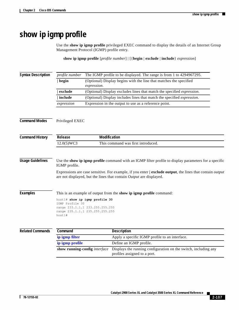
Chapter 2 Cisco IOS Commandsshow ip igmp profile
ic
show ip igmp profileUse theshow ip igmp profile privileged EXEC command to display the details of an Internet GroupManagement Protocol (IGMP) profile entry.
show ip igmp profile [profile number] | [{ begin | exclude | include} expression]
Syntax Description
Command Modes Privileged EXEC
Command History
Usage Guidelines Use theshow ip igmp profile command with an IGMP filter profile to display parameters for a specifIGMP profile.
Expressions are case sensitive. For example, if you enter| exclude output, the lines that containoutputare not displayed, but the lines that containOutput are displayed.
Examples This is an example of output from theshow ip igmp profile command:
host1# show ip igmp profile 30IGMP Profile 30range 233.1.1.1 233.255.255.255range 235.1.1.1 235.255.255.255host1#
Related Commands
profile number The IGMP profile to be displayed. The range is from 1 to 4294967295.
| begin (Optional) Display begins with the line that matches the specifiedexpression.
| exclude (Optional) Display excludes lines that match the specifiedexpression.
| include (Optional) Display includes lines that match the specifiedexpression.
expression Expression in the output to use as a reference point.
Release Modification
12.0(5)WC3 This command was first introduced.
Command Description
ip igmp filter Apply a specific IGMP profile to an interface.
ip igmp profile Define an IGMP profile.
show running-config interface Displays the running configuration on the switch, including anyprofiles assigned to a port.
2-107Catalyst 2900 Series XL and Catalyst 3500 Series XL Command Reference
78-12155-02

Chapter 2 Cisco IOS Commandsshow mac-address-table
singtions
show mac-address-tableUse theshow mac-address-table user EXEC command to display the MAC address table.
show mac-address-table[static | dynamic | secure | self | aging-time | count][addresshw-addr] [ interface interface] [atm slot/port] [vlan vlan-id]
Syntax Description
Command Modes User EXEC
Command History
Usage Guidelines This command displays the MAC address table for the switch. Specific views can be defined by uthe optional keywords and values. If more than one optional keyword is used, then all of the condimust be true in order for that entry to be displayed.
Examples This is an example of output from theshow mac-address-table command:
Switch> show mac-address-table
Dynamic Addresses Count: 9Secure Addresses (User-defined) Count: 0Static Addresses (User-defined) Count: 0System Self Addresses Count: 41Total MAC addresses: 50Non-static Address Table:Destination Address Address Type VLAN Destination Port------------------- ------------ ---- --------------------0010.0de0.e289 Dynamic 1 FastEthernet0/1
static (Optional) Display only the static addresses.
dynamic (Optional) Display only the dynamic addresses.
secure (Optional) Display only the secure addresses.
self (Optional) Display only addresses added by the switch itself.
aging-time (Optional) Display aging-time for dynamic addresses for all VLANs.
count (Optional) Display a count for different kinds of MAC addresses.
addresshw-addr (Optional) Display information for a specific address.
interface interface (Optional) Display addresses for a specific port.
atm slot/port (Optional) Add dynamic addresses to ATM moduleslot/port. Use 1 or 2 forthe slot number. Use 0 as the port number.
vlan vlan-id (Optional) Display addresses for a specific VLAN. Valid IDs are from1 to 1005; do not enter leading zeroes.
Release Modification
11.2(8)SA This command was first introduced.
11.2(8)SA3 Theself, aging-time, count, andvlan vlan-id keywords were added.
11.2(8)SA5 Theatm slot/port keywords were added.
2-108Catalyst 2900 Series XL and Catalyst 3500 Series XL Command Reference
78-12155-02

Chapter 2 Cisco IOS Commandsshow mac-address-table
0010.7b00.1540 Dynamic 2 FastEthernet0/50010.7b00.1545 Dynamic 2 FastEthernet0/50060.5cf4.0076 Dynamic 1 FastEthernet0/10060.5cf4.0077 Dynamic 1 FastEthernet0/10060.5cf4.1315 Dynamic 1 FastEthernet0/10060.70cb.f301 Dynamic 1 FastEthernet0/100e0.1e42.9978 Dynamic 1 FastEthernet0/100e0.1e9f.3900 Dynamic 1 FastEthernet0/1
Related Commands Command Description
clear mac-address-table Deletes entries from the MAC address table.
2-109Catalyst 2900 Series XL and Catalyst 3500 Series XL Command Reference
78-12155-02

Chapter 2 Cisco IOS Commandsshow mac-address-table notification
ll
show mac-address-table notificationUse theshow mac-address-table notificationprivileged EXEC command to display the globalparameters for the MAC address notification feature.
show mac-address-table notification[ interface interface id] | [{ begin | exclude | include}expression]
Syntax Description
Defaults This command has no default setting.
Command Modes Privileged EXEC
Command History
Usage Guidelines Use theshow mac-address-table notificationcommand without keywords to display parameters for ainterfaces.
Use this command with theinterface keyword to display parameters for a specific interface.
Expressions are case sensitive. For example, if you enter| exclude output, the lines that containoutputare not displayed, but the lines that containOutput are displayed.
Examples This is an example of output from theshow mac-address-table notification command:
Switch# show mac-address-table notificationMAC Notification Feature is Enabled on the switchInterval between Notification Traps : 10 secsNumber of MAC Addresses Added : 18Number of MAC Addresses Removed : 15Number of Notifications sent to NMS : 28Maximum Number of entries configured in History Table : 5Current History Table Length : 5MAC Notification Traps are EnabledHistory Table contents----------------------History Index 3, Entry Timestamp 1790800, Despatch Timestamp 1790800MAC Changed Message :Operation: Deleted Vlan: 1 MAC Addr: 00c0.4301.101b Dot1dBasePort:16
interface interface-id (Optional) Specify a interface.
| begin (Optional) Display begins with the line that matches the specifiedexpression.
| exclude (Optional) Display excludes lines that match the specifiedexpression.
| include (Optional) Display includes lines that match the specifiedexpression.
expression Expression in the output to use as a reference point.
Release Modification
12.0(5)WC3 Thenotification keyword was added.
2-110Catalyst 2900 Series XL and Catalyst 3500 Series XL Command Reference
78-12155-02

Chapter 2 Cisco IOS Commandsshow mac-address-table notification
History Index 4, Entry Timestamp 1794810, Despatch Timestamp 1794810MAC Changed Message :Operation: Added Vlan: 1 MAC Addr: 00c0.4301.101b Module: 0 Port: 2
History Index 0, Entry Timestamp 1825868, Despatch Timestamp 1825868MAC Changed Message :Operation: Deleted Vlan: 1 MAC Addr: 00c0.4301.101b Module: 0 Port: 2
History Index 1, Entry Timestamp 1850929, Despatch Timestamp 1850929MAC Changed Message :Operation: Added Vlan: 1 MAC Addr: 00c0.4301.101b Module: 0 Port: 2
History Index 2, Entry Timestamp 1880988, Despatch Timestamp 1880988MAC Changed Message :Operation: Deleted Vlan: 1 MAC Addr: 00c0.4301.101b Module: 0 Port: 2
Switch#
This is an example of output from theshow mac-address-table notification interfacecommand for allinterfaces on a switch:
MAC Notification Flags For All Ethernet Interfaces :----------------------------------------------------Interface MAC Added Trap MAC Removed Trap--------- -------------- ----------------FastEthernet0/1 Disabled DisabledFastEthernet0/2 Disabled DisabledFastEthernet0/3 Disabled DisabledFastEthernet0/4 Enabled EnabledFastEthernet0/5 Disabled DisabledFastEthernet0/6 Disabled DisabledFastEthernet0/7 Disabled DisabledFastEthernet0/8 Disabled DisabledFastEthernet0/9 Disabled DisabledFastEthernet0/10 Disabled DisabledFastEthernet0/11 Disabled DisabledFastEthernet0/12 Disabled DisabledFastEthernet0/13 Disabled DisabledFastEthernet0/14 Disabled DisabledFastEthernet0/15 Disabled DisabledFastEthernet0/16 Disabled DisabledFastEthernet0/17 Disabled DisabledFastEthernet0/18 Disabled DisabledFastEthernet0/19 Disabled DisabledFastEthernet0/20 Disabled DisabledFastEthernet0/21 Disabled DisabledFastEthernet0/22 Disabled DisabledFastEthernet0/23 Disabled DisabledFastEthernet0/24 Disabled Disabled
This is an example of output from theshow mac-address-table notification interfaceinterface-idcommand for one interface on a switch:
Interface MAC Added Trap MAC Removed Trap--------- -------------- ----------------FastEthernet0/4 Enabled Enabled
Switch#
2-111Catalyst 2900 Series XL and Catalyst 3500 Series XL Command Reference
78-12155-02
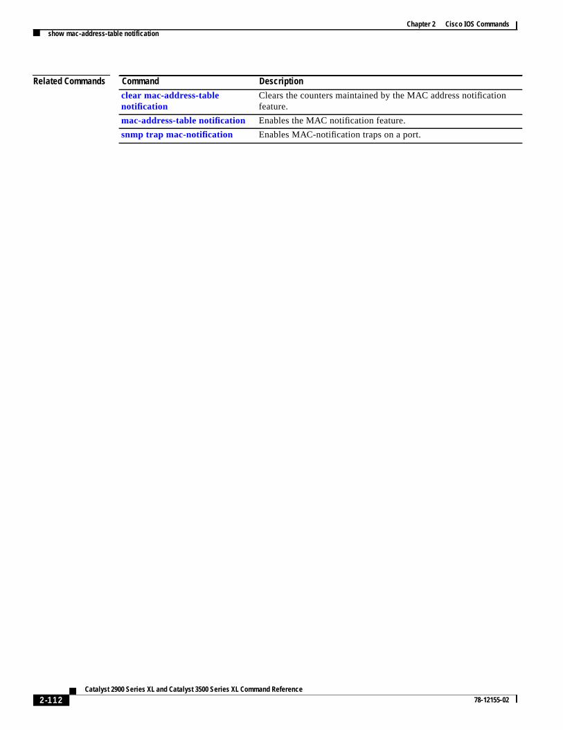
Chapter 2 Cisco IOS Commandsshow mac-address-table notification
Related Commands Command Description
clear mac-address-tablenotification
Clears the counters maintained by the MAC address notificationfeature.
mac-address-table notification Enables the MAC notification feature.
snmp trap mac-notification Enables MAC-notification traps on a port.
2-112Catalyst 2900 Series XL and Catalyst 3500 Series XL Command Reference
78-12155-02

Chapter 2 Cisco IOS Commandsshow mvr
um
t
t
.
show mvrUse theshow mvr privileged EXEC command without keywords to display the multicast VLANregistration (MVR) global parameter values, including whether or not MVR is enabled, the maximquery response time, and the multicast VLAN number.
show mvr
Syntax Description This command has no keywords.
Command Modes Privileged EXEC
Command History
Examples This example shows how to view the MVR global parameter values:
Switch# show mvrMVR EnabledMVR multicast vlan: 2MVR Current multicast groups: 1MVR Global query response time: 100 (tenths of sec)
Related Commands
Release Modification
12.0(5)XW This command was first introduced.
Command Description
show mvr interface Displays the configured MVR interfaces or displays the multicasgroups to which a receiver port belongs.
show mvr members Displays all receiver ports that are members of an MVR multicasgroup.
mvr (global configuration) (globalconfiguration mode)
Enables and configures multicast VLAN registration on the switch
mvr (interface configuration)(interface configuration mode)
Configures MVR ports.
2-113Catalyst 2900 Series XL and Catalyst 3500 Series XL Command Reference
78-12155-02
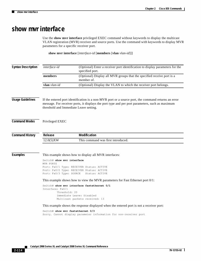
Chapter 2 Cisco IOS Commandsshow mvr interface
VR
r
show mvr interfaceUse theshow mvr interfaceprivileged EXEC command without keywords to display the multicastVLAN registration (MVR) receiver and source ports. Use the command with keywords to display Mparameters for a specific receiver port.
show mvr interface [interface-id[members[vlan vlan-id]]]
Syntax Description
Usage Guidelines If the entered port identification is a non-MVR port or a source port, the command returns an erromessage. For receiver ports, it displays the port type and per port parameters, such as maximumthreshold and Immediate Leave setting.
Command Modes Privileged EXEC
Command History
Examples This example shows how to display all MVR interfaces:
Switch# show mvr interfaceMVR PORTSPort: Fa0/1 Type: RECEIVER Status: ACTIVEPort: Fa0/2 Type: RECEIVER Status: ACTIVEPort: Fa0/3 Type: SOURCE Status: ACTIVE
This example shows how to view the MVR parameters for Fast Ethernet port 0/1:
Switch# show mvr interface fastethernet 0/1Interface: Fa0/1 Threshold: 20 Immediate Leave: Disabled Multicast packets received: 13
This example shows the response displayed when the entered port is not a receiver port:
Switch# show mvr fastethernet 0/3Sorry, Cannot display parameter information for non-receiver port
interface-id (Optional) Enter a receiver port identification to display parameters for thespecified port.
members (Optional) Display all MVR groups that the specified receive port is amember of.
vlan vlan-id (Optional) Display the VLAN to which the receiver port belongs.
Release Modification
12.0(5)XW This command was first introduced.
2-114Catalyst 2900 Series XL and Catalyst 3500 Series XL Command Reference
78-12155-02

Chapter 2 Cisco IOS Commandsshow mvr interface
.
Related Commands Command Description
show mvr Displays the global MVR configuration on the switch.
show mvr members Displays all receiver ports that are members of an MVR multicastgroup.
mvr (global configuration) (globalconfiguration mode)
Enables and configures multicast VLAN registration on the switch
mvr (interface configuration)(interface configuration mode)
Configures MVR ports.
2-115Catalyst 2900 Series XL and Catalyst 3500 Series XL Command Reference
78-12155-02

Chapter 2 Cisco IOS Commandsshow mvr members
rs
all
ris
show mvr membersUse theshow mvr membersprivileged EXEC command to display all receiver ports that are membeof an IP multicast group.
show mvr members[ ip-address]
Syntax Description
Usage Guidelines Theshow mvr members command only applies to receiver ports. All source ports are members ofmulticast groups.
Command Modes Privileged EXEC
Command History
Examples This example shows how to view the members of any IP multicast group:
Switch# show mvr membersMVR Group IP:239.255.0.1 Vlan 2 Interface:Fa0/16 DYNAMIC ACTIVE Vlan 2 Interface:Fa0/17 DYNAMIC ACTIVE
MVR Group IP:239.255.0.2 Vlan 2 Interface:Fa0/15 DYNAMIC ACTIVE Vlan 2 Interface:Fa0/17 DYNAMIC ACTIVE Vlan 2 Interface:Fa0/20 DYNAMIC ACTIVE
MVR Group IP:239.255.0.3 Vlan 2 Interface:Fa0/23 DYNAMIC ACTIVE Vlan 2 Interface:Fa0/16 DYNAMIC ACTIVE
MVR Group IP:239.255.0.4 Vlan 2 Interface:Fa0/26 DYNAMIC ACTIVE Vlan 2 Interface:Fa0/16 DYNAMIC ACTIVE Vlan 2 Interface:Fa0/23 DYNAMIC ACTIVE
MVR Group IP:239.255.0.5 Vlan 2 Interface:Fa0/15 DYNAMIC ACTIVE Vlan 2 Interface:Fa0/14 DYNAMIC ACTIVE
MVR Group IP:239.255.0.6 Vlan 2 Interface:Fa0/17 DYNAMIC ACTIVE Vlan 2 Interface:Fa0/18 DYNAMIC ACTIVE Vlan 2 Interface:Fa0/20 DYNAMIC ACTIVE Vlan 2 Interface:Fa0/23 DYNAMIC ACTIVE Vlan 2 Interface:Fa0/15 DYNAMIC ACTIVE
ip-address (Optional) The IP multicast address. If the address is entered, all receiveports that are members of the multicast group are displayed. If no addressentered, all members of all MVR groups are listed.
Release Modification
12.0(5)XW This command was first introduced.
2-116Catalyst 2900 Series XL and Catalyst 3500 Series XL Command Reference
78-12155-02

Chapter 2 Cisco IOS Commandsshow mvr members
This example shows how to view the members of the IP multicast group 239.255.0.4:
Switch# show mvr members 239.255.0.4MVR Group IP:239.255.0.4 Vlan 2 Interface:Fa0/26 DYNAMIC ACTIVE Vlan 2 Interface:Fa0/16 DYNAMIC ACTIVE Vlan 2 Interface:Fa0/23 DYNAMIC ACTIVE
Related Commands Command Description
show mvr Displays the global MVR configuration on the switch.
show mvr interface Displays the configured MVR interfaces or displays the multicastgroups to which a receiver port belongs.
mvr (global configuration) (globalconfiguration mode)
Enables and configures multicast VLAN registration on theswitch.
mvr (interface configuration)(interface configuration mode)
Configures MVR ports.
2-117Catalyst 2900 Series XL and Catalyst 3500 Series XL Command Reference
78-12155-02

Chapter 2 Cisco IOS Commandsshow port block
show port blockUse theshow port block privileged EXEC command to display the blocking of unicast or multicastflooding to a port.
show port block { unicast | multicast} [ interface-id |vlan number]
Syntax Description
Command Modes Privileged EXEC
Command History
Usage Guideliness If the variableinterface is omitted, theshow port block unicast and show port block multicastcommands display packet blocking information on all ports.
Examples This is an example of output from theshow port block command:
Switch# show port block unicast fa0/8
FastEthernet0/8 is blocked from unknown unicast addresses
Related Commands
unicast Display whether or not ports are blocking unicast packets.
multicast Display whether or not ports are blocking multicast packets.
interface-id (Optional) ID of the module and port.
vlan number (Optional) VLAN number from 1 to 1000. Do not enter leading zeroes.
Release Modification
11.2(8)SA This command was first introduced.
Command Description
port block Blocks the flooding of unknown unicast or multicast packets to a port.
2-118Catalyst 2900 Series XL and Catalyst 3500 Series XL Command Reference
78-12155-02

Chapter 2 Cisco IOS Commandsshow port group
p.
p.
show port groupUse theshow port group privileged EXEC command to display the ports that belong to a port grou
show port group [group-number]
Syntax Description
Command Modes Privileged EXEC
Command History
Usage Guidelines If the variablegroup-numberis omitted, theshow port group command displays all port groups on theswitch.
Examples This is an example of output from theshow port group command:
Switch# show port group 1
Group Interface----- --------------- 1 FastEthernet0/1 1 FastEthernet0/4
Related Commands
group-number (Optional)Port group to which the port is assigned.
Release Modification
11.2(8)SA3 This command was first introduced.
Command Description
port group Assigns a port to a Fast EtherChannel or Gigabit EtherChannel port grou
2-119Catalyst 2900 Series XL and Catalyst 3500 Series XL Command Reference
78-12155-02

Chapter 2 Cisco IOS Commandsshow port monitor
rt
show port monitorUse theshow port monitor privileged EXEC command to display the ports for which Switched PoAnalyzer (SPAN) port monitoring is enabled.
show port monitor [ interface-id |vlan number]
Syntax Description
Command Modes Privileged EXEC
Command History
Usage Guidelines If the variableinterface is omitted, theshow port monitor command displays all monitor ports on theswitch.
Examples This is an example of output from theshow port monitor command:
Switch# show port monitor fa0/8
Monitor Port Port Being Monitored------------------ --------------------FastEthernet0/8 FastEthernet0/1FastEthernet0/8 FastEthernet0/2FastEthernet0/8 FastEthernet0/3FastEthernet0/8 FastEthernet0/4
Related Commands
interface-id (Optional) ID of the module and port enabled for SPAN.
vlan number (Optional) VLAN number from 1 to 1000. Do not enter leading zeroes.
Release Modification
11.2(8)SA This command was first introduced.
Command Description
port monitor Enables SPAN port monitoring on a port.
2-120Catalyst 2900 Series XL and Catalyst 3500 Series XL Command Reference
78-12155-02

Chapter 2 Cisco IOS Commandsshow port network
show port networkUse theshow port network privileged EXEC command to display the network port defined for theswitch or VLAN.
show port network [ interface-id |vlan number]
Syntax Description
Command Modes Privileged EXEC
Command History
Usage Guidelines If the variableinterfaceis omitted, theshow port network command displays all network ports on theswitch.
Examples This is an example of output from theshow port network command:
Switch# show port network
Network Port VLAN ID------------ -------FastEthernet0/11 1
Related Commands
interface-id (Optional) ID of the module and port.
vlan number (Optional) VLAN number from 1 to 1000. Do not enter leading zeroes.
Release Modification
11.2(8)SA4 This command was first introduced.
Command Description
port network Defines a port as the switch network port. All traffic with unknown unicastaddresses is forwarded to the network port on the same VLAN.
2-121Catalyst 2900 Series XL and Catalyst 3500 Series XL Command Reference
78-12155-02

Chapter 2 Cisco IOS Commandsshow port protected
ts.
show port protectedUse theshow port protectedprivileged EXEC command to display the port protected mode for all por
show port protected
Syntax Description This command has no keywords or options.
Command Modes Privileged EXEC
Command History
Examples This is an example of output from theshow port protected command:
Switch# show port protected
FastEthernet0/3 is in protected modeGigabitEthernet1/1 is in protected mode
Related Commands
Release Modification
12.0(5)XU This command was first introduced.
Command Description
port protected Isolates unicast, multicast, and broadcast traffic at Layer 2 from otherprotected ports on the same switch.
2-122Catalyst 2900 Series XL and Catalyst 3500 Series XL Command Reference
78-12155-02
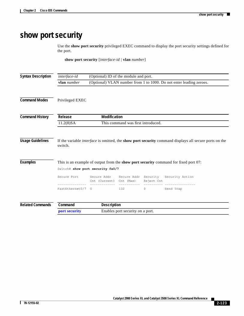
Chapter 2 Cisco IOS Commandsshow port security
or
show port securityUse theshow port security privileged EXEC command to display the port security settings defined fthe port.
show port security [ interface-id |vlan number]
Syntax Description
Command Modes Privileged EXEC
Command History
Usage Guidelines If the variableinterface is omitted, theshow port security command displays all secure ports on theswitch.
Examples This is an example of output from theshow port security command for fixed port 07:
Switch# show port security fa0/7
Secure Port Secure Addr Secure Addr Security Security Action Cnt (Current) Cnt (Max) Reject Cnt--------------- ------------- ----------- ---------- ----------------FastEthernet0/7 0 132 0 Send Trap
Related Commands
interface-id (Optional) ID of the module and port.
vlan number (Optional) VLAN number from 1 to 1000. Do not enter leading zeroes.
Release Modification
11.2(8)SA This command was first introduced.
Command Description
port security Enables port security on a port.
2-123Catalyst 2900 Series XL and Catalyst 3500 Series XL Command Reference
78-12155-02

Chapter 2 Cisco IOS Commandsshow port storm-control
e
ding
show port storm-controlUse theshow port storm-control privileged EXEC command to display the packet-storm controlinformation. This command also displays the action that the switch takes when the thresholds arreached.
show port storm-control [ interface] [{ broadcast | multicast | unicast | history}]
Syntax Description
Command Modes Privileged EXEC
Command History
Usage Guidelines If the variableinterface is omitted, theshow port storm-control command displays storm controlsettings on all ports on the switch.
You can display broadcast, multicast, or unicast packet-storm information by using the corresponkeyword.
Examples This is an example of output from theshow port storm-control command:
Switch# show port storm-control
Interface Filter State Trap State Rising Falling Current Traps Sent--------- ------------- ------------- ------ ------- ------- ----------Fa0/1 <inactive> <inactive> 1000 200 0 0Fa0/2 <inactive> <inactive> 500 250 0 0Fa0/3 <inactive> <inactive> 500 250 0 0Fa0/4 <inactive> <inactive> 500 250 0 0
Related Commands
interface (Optional) Port for which information is to be displayed.
broadcast (Optional) Display broadcast storm information.
multicast (Optional) Display multicast storm information.
unicast (Optional) Display unicast storm information.
history (Optional) Display storm history on a per-port basis.
Release Modification
11.2(8)SA This command was first introduced.
12.0(5)XU Thebroadcast, multicast, unicast, andhistory keywords were added.
Command Description
port storm-control Enables broadcast, multicast, or unicast storm control on a port.
2-124Catalyst 2900 Series XL and Catalyst 3500 Series XL Command Reference
78-12155-02

Chapter 2 Cisco IOS Commandsshow power inline
ort
show power inlineUse theshow power inlineprivileged EXEC command to display the power status for the specified por for all ports on the 3524-PWR-XL switch.
show power inline[ interface-id] [actual | configured]
Syntax Description
Command Modes Privileged EXEC
Command History
Examples This is an example of output from theshow power inline fa0/4 actual command:
Switch# show power inline fa0/4 actualInterface Power-------------------- -----FastEthernet0/4 no
Related Commands
interface-id (Optional) ID of the module and port.
actual (Optional) Display the current power status, which might not be the sameas the configured power.
configured (Optional) Display the configured power status.
Release Modification
12.0(5)XU This command was first introduced.
Command Description
power inline Determines how inline power is applied to devices on the specified FastEthernet port of the 3524-PWR-XL switch.
2-125Catalyst 2900 Series XL and Catalyst 3500 Series XL Command Reference
78-12155-02
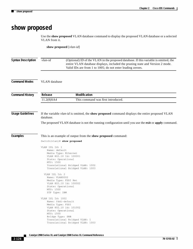
Chapter 2 Cisco IOS Commandsshow proposed
ted
.
show proposedUse theshow proposedVLAN database command to display the proposed VLAN database or a selecVLAN from it.
show proposed[vlan-id]
Syntax Description
Command Modes VLAN database
Command History
Usage Guidelines If the variablevlan-id is omitted, theshow proposed command displays the entire proposed VLANdatabase.
The proposed VLAN database is not the running configuration until you use theexit or apply command.
Examples This is an example of output from theshow proposed command:
Switch(vlan)# show proposed
VLAN ISL Id: 1 Name: default Media Type: Ethernet VLAN 802.10 Id: 100001 State: Operational MTU: 1500 Translational Bridged VLAN: 1002 Translational Bridged VLAN: 1003
VLAN ISL Id: 2 Name: VLAN0002 Media Type: FDDI Net VLAN 802.10 Id: 100002 State: Operational MTU: 1500 STP Type: IBM
VLAN ISL Id: 1002 Name: fddi-default Media Type: FDDI VLAN 802.10 Id: 101002 State: Operational MTU: 1500 Bridge Type: SRB Translational Bridged VLAN: 1 Translational Bridged VLAN: 1003
vlan-id (Optional) ID of the VLAN in the proposed database. If this variable is omitted, theentire VLAN database displays, included the pruning state and Version 2 modeValid IDs are from 1 to 1005; do not enter leading zeroes.
Release Modification
11.2(8)SA4 This command was first introduced.
2-126Catalyst 2900 Series XL and Catalyst 3500 Series XL Command Reference
78-12155-02
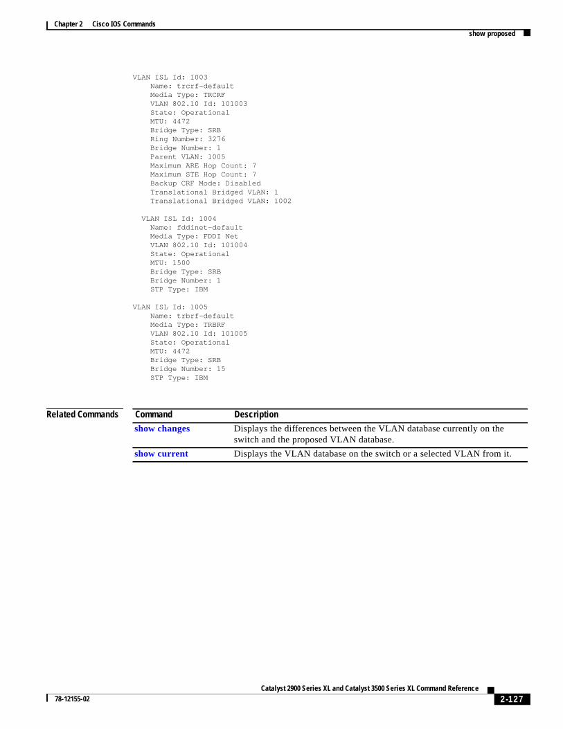
Chapter 2 Cisco IOS Commandsshow proposed
VLAN ISL Id: 1003 Name: trcrf-default Media Type: TRCRF VLAN 802.10 Id: 101003 State: Operational MTU: 4472 Bridge Type: SRB Ring Number: 3276 Bridge Number: 1 Parent VLAN: 1005 Maximum ARE Hop Count: 7 Maximum STE Hop Count: 7 Backup CRF Mode: Disabled Translational Bridged VLAN: 1 Translational Bridged VLAN: 1002
VLAN ISL Id: 1004 Name: fddinet-default Media Type: FDDI Net VLAN 802.10 Id: 101004 State: Operational MTU: 1500 Bridge Type: SRB Bridge Number: 1 STP Type: IBM
VLAN ISL Id: 1005 Name: trbrf-default Media Type: TRBRF VLAN 802.10 Id: 101005 State: Operational MTU: 4472 Bridge Type: SRB Bridge Number: 15 STP Type: IBM
Related Commands Command Description
show changes Displays the differences between the VLAN database currently on theswitch and the proposed VLAN database.
show current Displays the VLAN database on the switch or a selected VLAN from it.
2-127Catalyst 2900 Series XL and Catalyst 3500 Series XL Command Reference
78-12155-02
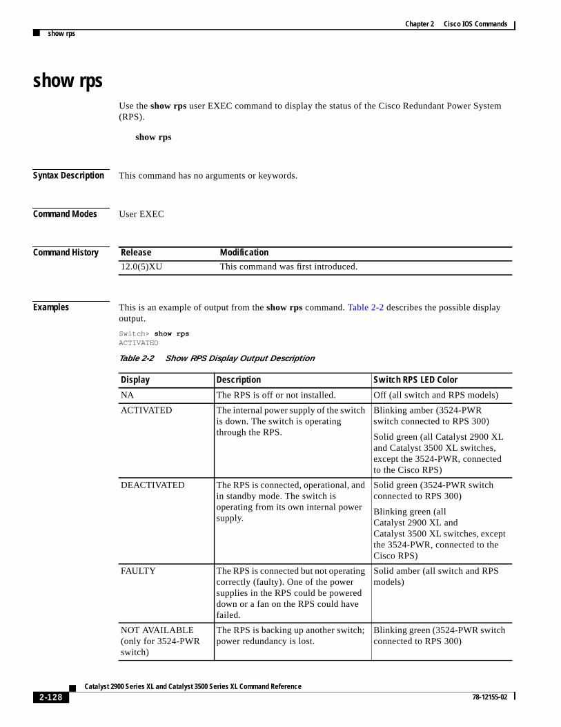
Chapter 2 Cisco IOS Commandsshow rps
m
show rpsUse theshow rps user EXEC command to display the status of the Cisco Redundant Power Syste(RPS).
show rps
Syntax Description This command has no arguments or keywords.
Command Modes User EXEC
Command History
Examples This is an example of output from theshow rpscommand.Table 2-2 describes the possible displayoutput.
Switch> show rpsACTIVATED
Release Modification
12.0(5)XU This command was first introduced.
Table 2-2 Show RPS Display Output Description
Display Description Switch RPS LED Color
NA The RPS is off or not installed. Off (all switch and RPS models)
ACTIVATED The internal power supply of the switchis down. The switch is operatingthrough the RPS.
Blinking amber (3524-PWRswitch connected to RPS 300)
Solid green (all Catalyst 2900 XLand Catalyst 3500 XL switches,except the 3524-PWR, connectedto the Cisco RPS)
DEACTIVATED The RPS is connected, operational, andin standby mode. The switch isoperating from its own internal powersupply.
Solid green (3524-PWR switchconnected to RPS 300)
Blinking green (allCatalyst 2900 XL andCatalyst 3500 XL switches, exceptthe 3524-PWR, connected to theCisco RPS)
FAULTY The RPS is connected but not operatingcorrectly (faulty). One of the powersupplies in the RPS could be powereddown or a fan on the RPS could havefailed.
Solid amber (all switch and RPSmodels)
NOT AVAILABLE(only for 3524-PWRswitch)
The RPS is backing up another switch;power redundancy is lost.
Blinking green (3524-PWR switchconnected to RPS 300)
2-128Catalyst 2900 Series XL and Catalyst 3500 Series XL Command Reference
78-12155-02
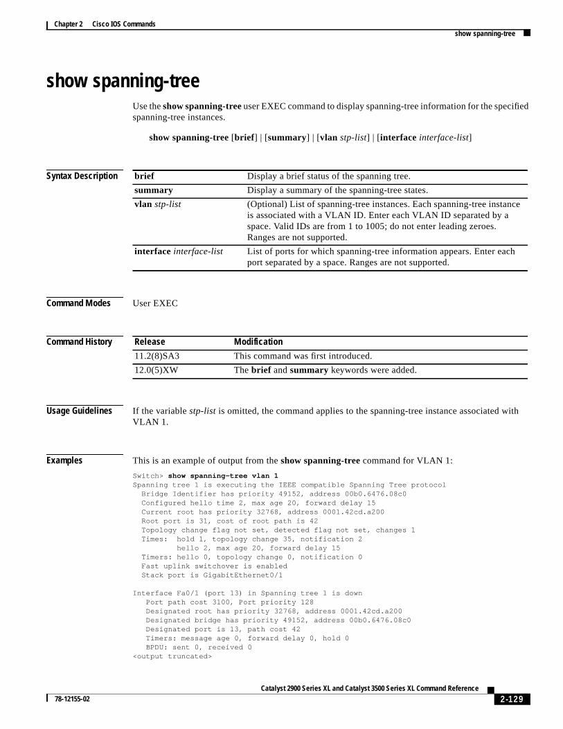
Chapter 2 Cisco IOS Commandsshow spanning-tree
ied
ith
e
show spanning-treeUse theshow spanning-treeuser EXEC command to display spanning-tree information for the specifspanning-tree instances.
show spanning-tree[brief ] | [summary] | [vlan stp-list] | [interface interface-list]
Syntax Description
Command Modes User EXEC
Command History
Usage Guidelines If the variablestp-list is omitted, the command applies to the spanning-tree instance associated wVLAN 1.
Examples This is an example of output from theshow spanning-treecommand for VLAN 1:
Switch> show spanning-tree vlan 1Spanning tree 1 is executing the IEEE compatible Spanning Tree protocol Bridge Identifier has priority 49152, address 00b0.6476.08c0 Configured hello time 2, max age 20, forward delay 15 Current root has priority 32768, address 0001.42cd.a200 Root port is 31, cost of root path is 42 Topology change flag not set, detected flag not set, changes 1 Times: hold 1, topology change 35, notification 2 hello 2, max age 20, forward delay 15 Timers: hello 0, topology change 0, notification 0 Fast uplink switchover is enabled Stack port is GigabitEthernet0/1
Interface Fa0/1 (port 13) in Spanning tree 1 is down Port path cost 3100, Port priority 128 Designated root has priority 32768, address 0001.42cd.a200 Designated bridge has priority 49152, address 00b0.6476.08c0 Designated port is 13, path cost 42 Timers: message age 0, forward delay 0, hold 0 BPDU: sent 0, received 0<output truncated>
brief Display a brief status of the spanning tree.
summary Display a summary of the spanning-tree states.
vlan stp-list (Optional) List of spanning-tree instances. Each spanning-tree instancis associated with a VLAN ID. Enter each VLAN ID separated by aspace. Valid IDs are from 1 to 1005; do not enter leading zeroes.Ranges are not supported.
interface interface-list List of ports for which spanning-tree information appears. Enter eachport separated by a space. Ranges are not supported.
Release Modification
11.2(8)SA3 This command was first introduced.
12.0(5)XW Thebrief andsummary keywords were added.
2-129Catalyst 2900 Series XL and Catalyst 3500 Series XL Command Reference
78-12155-02

Chapter 2 Cisco IOS Commandsshow spanning-tree
e
This is an example of output from theshow spanning-tree interfacecommand for port 3:
Switch> show spanning-tree interface fa0/3
Interface Fa0/3 (port 3) in Spanning tree 1 is down Port path cost 100, Port priority 128 Designated root has priority 6000, address 0090.2bba.7a40 Designated bridge has priority 32768, address 00e0.1e9f.4abf Designated port is 3, path cost 410 Timers: message age 0, forward delay 0, hold 0 BPDU: sent 0, received 0
This is an example of output from theshow spanning-tree summary command:
Switch> show spanning-tree summaryUplinkFast is enabledStack port is GigabitEthernet0/1
Name Blocking Listening Learning Forwarding STP Active-------------------- -------- --------- -------- ---------- ----------VLAN1 13 0 0 1 14VLAN2 1 0 0 1 2VLAN3 1 0 0 1 2<output truncated>
Related Commands Command Description
spanning-tree Enables STP on a VLAN.
spanning-tree forward-time Specifies the forwarding-time for the specified spanning-treeinstances.
spanning-tree max-age Changes the interval between messages that the spanning treereceives from the root switch.
spanning-tree port-priority Configures a port priority, which is used when two switches tie forposition as the root switch.
spanning-tree protocol Specifies the STP version to be used for specified spanning-treinstances.
2-130Catalyst 2900 Series XL and Catalyst 3500 Series XL Command Reference
78-12155-02

Chapter 2 Cisco IOS Commandsshow tacacs
show tacacsUse theshow tacacs user EXEC command to display various Terminal Access Controller AccessControl System Plus (TACACS+) server statistics.
show tacacs
Syntax Description This command has no arguments.
Command Modes User EXEC
Command History
Examples This is an example of output from theshow tacacs command:
Switch> show tacacs
Server:172.20.128.113/49:opens=4 closes=4 aborts=0 errors=0 packets in=6 packets out=6 no connection
Release Modification
11.2(8)SA6 This command was first introduced.
2-131Catalyst 2900 Series XL and Catalyst 3500 Series XL Command Reference
78-12155-02

Chapter 2 Cisco IOS Commandsshow udld
or
show udldUse theshow udld user EXEC command to display UniDirectional Link Detection (UDLD) status fall ports or the specified port.
show udld [ interface-id]
Syntax Description
Command Modes User EXEC
Command History
Examples This is an example of output from theshow udld fa0/11command. In this display, UDLD is enabled onboth ends of the link, and UDLD detects that the link is bidirectional.Table 2-3 describes the fields inthis display.
Switch> show udld fa0/11Interface Fa0/11Port enable configuration setting: Follows global settingOperational enable state: EnabledCurrent bidirectional state: BidirectionalMessage interval: 60Message timer: 38Current operational state: AdvertisementTime out interval: 5Time out timer: 0Restart counter: 0Neighbors counter: 1Probe counter: 0No multiple neighbors detectedCurrent pool id: 1 --- Cache entry 1 (0x69D8E4) Device name: aunguyen-1.cisco.com Device MAC address: 00:E0:1E:9F:85:80 Port ID: Fa1/1 Expiration time: 159 Cache device ID: 1 Resynch flag clear Current neighbor state: Bidirectional Most recent message type received: Probe Message interval: 5 Neighbor echo 1 device: 00:50:0F:08:A4:00 Neighbor echo 1 port: Fa0/11
interface-id (Optional) ID of the module and port or a VLAN ID. Valid IDs are from 1to 1000.
Release Modification
12.0(5)XU This command was first introduced.
2-132Catalyst 2900 Series XL and Catalyst 3500 Series XL Command Reference
78-12155-02
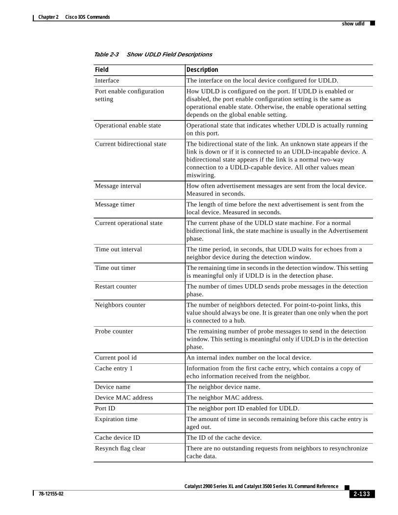
Chapter 2 Cisco IOS Commandsshow udld
g
ng
e
ce.
e
g
ion
t
ion
is
ize
Table 2-3 Show UDLD Field Descriptions
Field Description
Interface The interface on the local device configured for UDLD.
Port enable configurationsetting
How UDLD is configured on the port. If UDLD is enabled ordisabled, the port enable configuration setting is the same asoperational enable state. Otherwise, the enable operational settindepends on the global enable setting.
Operational enable state Operational state that indicates whether UDLD is actually runnion this port.
Current bidirectional state The bidirectional state of the link. An unknown state appears if thlink is down or if it is connected to an UDLD-incapable device. Abidirectional state appears if the link is a normal two-wayconnection to a UDLD-capable device. All other values meanmiswiring.
Message interval How often advertisement messages are sent from the local deviMeasured in seconds.
Message timer The length of time before the next advertisement is sent from thlocal device. Measured in seconds.
Current operational state The current phase of the UDLD state machine. For a normalbidirectional link, the state machine is usually in the Advertisementphase.
Time out interval The time period, in seconds, that UDLD waits for echoes from aneighbor device during the detection window.
Time out timer The remaining time in seconds in the detection window. This settinis meaningful only if UDLD is in the detection phase.
Restart counter The number of times UDLD sends probe messages in the detectphase.
Neighbors counter The number of neighbors detected. For point-to-point links, thisvalue should always be one. It is greater than one only when the poris connected to a hub.
Probe counter The remaining number of probe messages to send in the detectwindow. This setting is meaningful only if UDLD is in the detectionphase.
Current pool id An internal index number on the local device.
Cache entry 1 Information from the first cache entry, which contains a copy ofecho information received from the neighbor.
Device name The neighbor device name.
Device MAC address The neighbor MAC address.
Port ID The neighbor port ID enabled for UDLD.
Expiration time The amount of time in seconds remaining before this cache entryaged out.
Cache device ID The ID of the cache device.
Resynch flag clear There are no outstanding requests from neighbors to resynchroncache data.
2-133Catalyst 2900 Series XL and Catalyst 3500 Series XL Command Reference
78-12155-02

Chapter 2 Cisco IOS Commandsshow udld
es
ent
ho
Related Commands
Current neighbor state The neighbor’s current state. If both the local and neighbor devicare running UDLD normally, the neighbor state and local stateshould be bidirectional. If the link is down or the neighbor is notUDLD-capable, no cache entries are displayed.
Most recent message typereceived
The type of message received from the neighbor.
Message interval The rate, in seconds, at which the neighbor is sending advertisemmessages.
Neighbor echo 1 device The MAC address of the neighbors neighbor from which the ecoriginated.
Neighbor echo 1 port The port ID of the neighbor from which the echo originated.
Table 2-3 Show UDLD Field Descriptions (continued)
Field Description
Command Description
udld Enables UDLD on a port.
udld enable Enables UDLD on all ports on the switch.
udld reset Resets any interface that has been shut down by UDLD.
2-134Catalyst 2900 Series XL and Catalyst 3500 Series XL Command Reference
78-12155-02

Chapter 2 Cisco IOS Commandsshow version
show versionUse theshow versionuser EXEC command to display version information for the hardware andfirmware.
show version
Syntax Description The command has no arguments.
Command Modes User EXEC
Command History
Examples This is an example of output from theshow version command:
Switch> show version
Cisco Internetwork Operating System Technology SoftwareIOS Technology(tm) C3500XL Software (C3500XL-C3H2S-M), Version 12.0Copyright (c) 1986-1998 by cisco Systems, Inc.Compiled Mon 22-Nov-99 10:51 by mollynImage text-base: 0x00003000, data-base: 0x0031B6B4
ROM: Bootstrap program is C3500XL boot loader
Switch uptime is 1 hour, 32 minutesSystem returned to ROM by reloadSystem image file is "flash:c3500XL-c3h2s-mz-120.0.0.29-XU.bin"
cisco WS-C3524-XL (PowerPC403) processor (revision 0x01) with 8192K/1024K bytesof memory.Processor board ID 0x12, with hardware revision 0x00Last reset from warm-reset
Processor is running Enterprise Edition SoftwareCluster command switch capableCluster member switch capable24 FastEthernet/IEEE 802.3 interface(s)2 Gigabit Ethernet/IEEE 802.3 interface(s)
32K bytes of flash-simulated non-volatile configuration memory.Base ethernet MAC Address: 00:D0:79:6D:2F:00Motherboard assembly number: 73-3904-08Power supply part number: 34-0851-02Motherboard serial number: FAA03269NLKPower supply serial number: PHI031200D2Model revision number: A0Model number: WS-C3524-XL-ASystem serial number: FAA0328K01GConfiguration register is 0xF
Release Modification
11.2(8)SA This command was first introduced.
2-135Catalyst 2900 Series XL and Catalyst 3500 Series XL Command Reference
78-12155-02

Chapter 2 Cisco IOS Commandsshow vlan
e
show vlanUse theshow vlan user EXEC command to display the parameters for all configured VLANs or onVLAN (if the VLAN ID or name is specified) in the administrative domain.
show vlan [brief | id vlan-id | namevlan-name]
Syntax Description
Command Modes User EXEC
Command History
Examples This is an example of output from theshow vlan command:
Switch> show vlanVLAN Name Status Ports---- -------------------------------- --------- -------------------------------1 default active Fa0/1, Fa0/2, Fa0/3, Fa0/4, Fa0/5, Fa0/6, Fa0/7, Fa0/8, Fa0/9, Fa0/10, Fa0/11, Fa0/12, Fa0/13, Fa0/14, Fa0/15, Fa0/16, Fa0/17, Fa0/18, Fa0/19, Fa0/20, Fa0/21, Fa0/22, Fa0/23, Fa0/24, Gi0/1, Gi0/21002 fddi-default active1003 token-ring-default active1004 fddinet-default active1005 trnet-default active
VLAN Type SAID MTU Parent RingNo BridgeNo Stp Trans1 Trans2---- ----- ---------- ----- ------ ------ -------- ---- ------ ------1 enet 100001 1500 - - - - 1002 10036 fdnet 100006 1500 - - - ieee 0 07 trnet 100007 1500 - - 5 ieee 0 01002 fddi 101002 1500 - - - - 1 10031003 tr 101003 1500 1005 3276 - - 1 10021004 fdnet 101004 1500 - - 1 ibm 0 01005 trnet 101005 1500 - - 15 ibm 0 0
brief (Optional) Display one line for each VLAN with the VLAN name, status,and its ports
id vlan-id (Optional) ID of the VLAN displayed. Valid IDs are from 1 to 1005; do notenter leading zeroes.
namevlan-name (Optional) Name of the VLAN displayed. The VLAN name is an ASCIIstring from 1 to 32 characters.
Release Modification
11.2(8)SA3 This command was first introduced.
11.2(8)SA4 Thenamevlan-name keywords were added.
2-136Catalyst 2900 Series XL and Catalyst 3500 Series XL Command Reference
78-12155-02
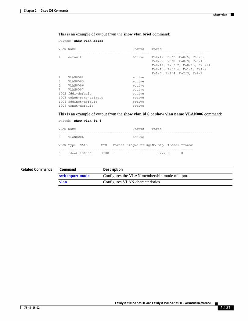
Chapter 2 Cisco IOS Commandsshow vlan
This is an example of output from theshow vlan brief command:
Switch> show vlan brief
VLAN Name Status Ports---- -------------------------------- --------- -------------------------------1 default active Fa0/1, Fa0/2, Fa0/5, Fa0/6, Fa0/7, Fa0/8, Fa0/9, Fa0/10, Fa0/11, Fa0/12, Fa0/13, Fa0/14, Fa0/15, Fa0/16, Fa1/1, Fa1/2, Fa1/3, Fa1/4, Fa2/3, Fa2/42 VLAN0002 active3 VLAN0003 active6 VLAN0006 active7 VLAN0007 active1002 fddi-default active1003 token-ring-default active1004 fddinet-default active1005 trnet-default active
This is an example of output from theshow vlan id 6or show vlan name VLAN006 command:
Switch> show vlan id 6
VLAN Name Status Ports---- -------------------------------- --------- -------------------------------6 VLAN0006 active
VLAN Type SAID MTU Parent RingNo BridgeNo Stp Trans1 Trans2---- ----- ---------- ----- ------ ------ -------- ---- ------ ------6 fdnet 100006 1500 - - - ieee 0 0
Related Commands Command Description
switchport mode Configures the VLAN membership mode of a port.
vlan Configures VLAN characteristics.
2-137Catalyst 2900 Series XL and Catalyst 3500 Series XL Command Reference
78-12155-02
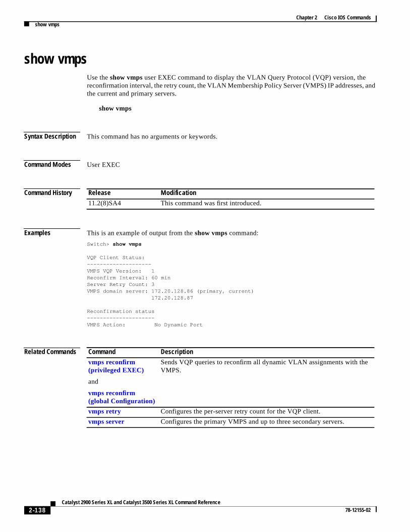
Chapter 2 Cisco IOS Commandsshow vmps
and
show vmpsUse theshow vmps user EXEC command to display the VLAN Query Protocol (VQP) version, thereconfirmation interval, the retry count, the VLAN Membership Policy Server (VMPS) IP addresses,the current and primary servers.
show vmps
Syntax Description This command has no arguments or keywords.
Command Modes User EXEC
Command History
Examples This is an example of output from theshow vmps command:
Switch> show vmps
VQP Client Status:--------------------VMPS VQP Version: 1Reconfirm Interval: 60 minServer Retry Count: 3VMPS domain server: 172.20.128.86 (primary, current) 172.20.128.87
Reconfirmation status---------------------VMPS Action: No Dynamic Port
Related Commands
Release Modification
11.2(8)SA4 This command was first introduced.
Command Description
vmps reconfirm(privileged EXEC)
and
vmps reconfirm(global Configuration)
Sends VQP queries to reconfirm all dynamic VLAN assignments with theVMPS.
vmps retry Configures the per-server retry count for the VQP client.
vmps server Configures the primary VMPS and up to three secondary servers.
2-138Catalyst 2900 Series XL and Catalyst 3500 Series XL Command Reference
78-12155-02

Chapter 2 Cisco IOS Commandsshow vmps statistics
)
show vmps statisticsUse theshow vmps statisticsprivileged EXEC command to display the VLAN Query Protocol (VQPclient-side statistics and counters.
show vmps statistics
Syntax Description This command has no arguments or keywords.
Command Modes Privileged EXEC
Command History
Examples This is an example of output from theshow vmps statisticscommand.Table 2-4describes each field inthe display.
Switch# show vmps statistics
VMPS Client Statistics----------------------VQP Queries: 0VQP Responses: 0VMPS Changes: 0VQP Shutdowns: 0VQP Denied: 0VQP Wrong Domain: 0VQP Wrong Version: 0VQP Insufficient Resource: 0
Release Modification
11.2(8)SA4 This command was first introduced.
2-139Catalyst 2900 Series XL and Catalyst 3500 Series XL Command Reference
78-12155-02

Chapter 2 Cisco IOS Commandsshow vmps statistics
hem
se
rt
tch
een
e
n
of,teed.
Related Commands
Table 2-4 Show VMPS Statistics Field Descriptions
Field Description
VQP Queries Number of queries sent by the client to the VLAN Membership PolicyServer (VMPS).
VQP Responses Number of responses sent to the client from the VMPS.
VMPS Changes Number of times that the VMPS changed from one server to another.
VQP Shutdowns Number of times that the VMPS sent a response to shut down the port. Tclient disables the port and removes all dynamic addresses on this port frothe address table. You must re-enable the port to restore connectivity.
VQP Denied Number of times that the VMPS denied the client request for securityreasons. When the VMPS response is to deny an address, no frame isforwarded to or from the workstation with that address (broadcast ormulticast frames are delivered to the workstation if the port has beenassigned to a VLAN). The client keeps the denied address in the addrestable as a blocked address to prevent further queries from being sent to thVMPS for each new packet received from this workstation. The client agesthe address if no new packets are received from this workstation on this powithin the aging time period.
VQP Wrong Domain Number of times that the management domain in the request does not mathe one for the VMPS. Any previous VLAN assignments of the port are notchanged. This response means that the server and the client have not bconfigured with the same VTP management domain.
VQP Wrong Version Number of times that the version field in the query packet contains a valuthat is higher than the version supported by the VMPS. The previous VLANassignment of the port is not changed. The switch sends only VMPS versio1 requests.
VQP InsufficientResource
Number of times that the VMPS is unable to answer the request becausea resource availability problem. If the retry limit has not yet been reachedthe client repeats the request with the same server or with the next alternaserver, depending on whether the per-server retry count has been reach
Command Description
clear vmps statistics Clears the statistics maintained by the VQP client.
2-140Catalyst 2900 Series XL and Catalyst 3500 Series XL Command Reference
78-12155-02

Chapter 2 Cisco IOS Commandsshow vtp
show vtpUse theshow vtp user EXEC command to display general information about the VLAN TrunkingProtocol (VTP) management domain, status, and counters.
show vtp { counters | status}
Syntax Description
Command Modes User EXEC
Command History
Examples This is an example of output from theshow vtp counters command.Table 2-5 describes each field inthe display.
Switch> show vtp counters
VTP statistics:Summary advertisements received : 38Subset advertisements received : 0Request advertisements received : 0Summary advertisements transmitted : 13Subset advertisements transmitted : 3Request advertisements transmitted : 0Number of config revision errors : 0Number of config digest errors : 0Number of V1 summary errors : 0
VTP pruning statistics:
Trunk Join Transmitted Join Received Summary advts received from non-pruning-capable device---------------- ---------------- ---------------- ---------------------------Fa0/9 827 824 0Fa0/10 827 823 0Fa0/11 827 823 0
counters Display the VTP counters for the switch.
status Display general information about the VTP management domain.
Release Modification
11.2(8)SA4 This command was first introduced.
2-141Catalyst 2900 Series XL and Catalyst 3500 Series XL Command Reference
78-12155-02

Chapter 2 Cisco IOS Commandsshow vtp
its
s
its
nknd
nkr
nk
r
Table 2-5 Show VTP Counters Field Descriptions
Field Description
Summary Advts Received Number of summary advertisements received by this switch ontrunk ports. Summary advertisements contain the managementdomain name, the configuration revision number, the updatetimestamp and identity, the authentication checksum, and thenumber of subset advertisements to follow.
Subset Advts Received Number of subset advertisements received by this switch on ittrunk ports. Subset advertisements contain all the information forone or more VLANs.
Request Advts Received Number of advertisement requests received by this switch on trunk ports. Advertisement requests normally request informationon all VLANs. They can also request information on a subset ofVLANs.
Summary Advts Transmitted Number of summary advertisements sent by this switch on its truports. Summary advertisements contain the management domainame, the configuration revision number, the update timestamp anidentity, the authentication checksum, and the number of subsetadvertisements to follow.
Subset Advts Transmitted Number of subset advertisements sent by this switch on its truports. Subset advertisements contain all the information for one omore VLANs.
Request Advts Transmitted Number of advertisement requests sent by this switch on its truports. Advertisement requests normally request information on allVLANs. They can also request information on a subset of VLANs.
No. of Configuration RevisionErrors
Number of revision errors.
Whenever you define a new VLAN, delete an existing one, suspendor resume an existing VLAN, or modify the parameters on anexisting VLAN, the configuration revision number of the switchincrements.
Revision errors increment whenever the switch receives anadvertisement whose revision number matches the revision numbeof the switch, but the MD5 digest values do not match. This errormeans that the VTP password in the two switches is different orthat the switches have different configurations.
These errors mean that the switch is filtering incomingadvertisements, which causes the VTP database to becomeunsynchronized across the network.
2-142Catalyst 2900 Series XL and Catalyst 3500 Series XL Command Reference
78-12155-02

Chapter 2 Cisco IOS Commandsshow vtp
s
t
This is an example of output from theshow vtp status command.Table 2-6 describes each field in thedisplay.
Switch> show vtp status
VTP Version : 2Configuration Revision : 1Maximum VLANs supported locally : 68Number of existing VLANs : 7VTP Operating Mode : ServerVTP Domain Name : test1VTP Pruning Mode : DisabledVTP V2 Mode : DisabledVTP Traps Generation : DisabledMD5 digest : 0x3D 0x02 0xD4 0x3A 0xC4 0x46 0xA1 0x03Configuration last modified by 172.20.130.52 at 3-4-93 22:25:
No. of Configuration DigestErrors
Number of MD5 digest errors.
Digest errors increment whenever the MD5 digest in the summarypacket and the MD5 digest of the received advertisementcalculated by the switch do not match. This error usually meansthat the VTP password in the two switches is different. To solvethis problem, make sure that the VTP password on all switches ithe same.
These errors mean that the switch is filtering incomingadvertisements, which causes the VTP database to becomeunsynchronized across the network.
No. of V1 Summary Errors Number of version 1 errors.
Version 1 summary errors increment whenever a switch in VTP V2mode receives a VTP version 1 frame. These errors mean that aleast one neighboring switch is either running VTP version 1 orVTP version 2 with V2-mode disabled. To solve this problem,change the configuration of the switches in VTP V2-mode todisabled.
Join Transmitted Number of VTP pruning messages transmitted on the trunk.
Join Received Number of VTP pruning messages received on the trunk.
Summary Advts Received fromnon-pruning-capable device
Number of VTP summary messages received on the trunk fromdevices that do not support pruning.
Table 2-5 Show VTP Counters Field Descriptions (continued)
Field Description
2-143Catalyst 2900 Series XL and Catalyst 3500 Series XL Command Reference
78-12155-02

Chapter 2 Cisco IOS Commandsshow vtp
or
g
Table 2-6 Show VTP Status Field Descriptions
Field Description
VTP Version Displays the VTP version operating on the switch. By default,Catalyst 2900 XL and Catalyst 3500 XL switches implementversion 1 but can be set to version 2.
Configuration Revision Configuration revision number on this switch.
Maximum VLANs SupportedLocally
Maximum number of VLANs supported locally.
Number of Existing VLANs Number of existing VLANs.
VTP Operating Mode Displays the VTP operating mode, which can be server, client, transparent.
Server: a switch in VTP server mode is enabled for VTP and sendsadvertisements. You can configure VLANs on it. The switchguarantees that it can recover all the VLAN information in the VTPdatabase from nonvolatile storage after reboot. By default, everyswitch is a VTP server.
Client: a switch in VTP client mode is enabled for VTP, can sendadvertisements, but does not have enough nonvolatile storage tostore VLAN configurations. You cannot configure VLANs on it.When a VTP client starts up, it does not transmit VTPadvertisements until it receives advertisements to initialize itsVLAN database.
Transparent: a switch in VTP transparent mode is disabled forVTP, does not transmit advertisements or learn fromadvertisements sent by other devices, and cannot affect VLANconfigurations on other devices in the network. The switch receivesVTP advertisements and forwards them on all trunk ports exceptthe one on which the advertisement was received. Theconfiguration of multi-VLAN ports causes the switch toautomatically enter transparent mode.
Note Catalyst 2912MF, 2924M, and Catalyst 3500 XL switchessupport up to 250 VLANs. All other Catalyst 2900 XLswitches support up to 64 VLANs. If you define more than250 or 64 or if the switch receives an advertisement thatcontains more than 250 or 64 VLANs, the switchautomatically enters VTP transparent mode and operateswith the VLAN configuration preceding the one that sent itinto transparent mode.
VTP Domain Name Name that identifies the administrative domain for the switch.
VTP Pruning Mode Displays whether pruning is enabled or disabled. Enabling pruninon a VTP server enables pruning for the entire managementdomain. Pruning restricts flooded traffic to those trunk links thatthe traffic must use to access the appropriate network devices.
2-144Catalyst 2900 Series XL and Catalyst 3500 Series XL Command Reference
78-12155-02

Chapter 2 Cisco IOS Commandsshow vtp
.
.n
Related Commands
VTP V2 Mode Displays if VTP version 2 mode is enabled. All VTP version 2switches operate in version 1 mode by default. Each VTP switchautomatically detects the capabilities of all the other VTP devices.A network of VTP devices should be configured to version 2 onlyif all VTP switches in the network can operate in version 2 mode
VTP Traps Generation Displays whether VTP traps are transmitted to a networkmanagement station.
MD5 Digest A 16-byte checksum of the VTP configuration.
Configuration Last Modified Displays the date and time of the last configuration modificationDisplays the IP address of the switch that caused the configuratiochange to the database.
Table 2-6 Show VTP Status Field Descriptions (continued)
Field Description
Command Description
clear vtp counters Clears the VTP and pruning counters.
vtp Configures the VTP mode.
2-145Catalyst 2900 Series XL and Catalyst 3500 Series XL Command Reference
78-12155-02

Chapter 2 Cisco IOS Commandsshutdown
entAN.
hasit can
own.
w
shutdownUse theshutdown interface configuration command to disable a port and to shut down the managemVLAN. Use theno form of this command to restart a disabled port or to activate the management VL
shutdown
no shutdown
Syntax Description This command has no arguments or keywords.
Command Modes Interface configuration
Command History
Usage Guidelines Theshutdown command for a port causes it to stop forwarding. You can enable the port with thenoshutdown command.
Theno shutdowncommand has no effect if the port is a static-access port assigned to a VLAN thatbeen deleted, suspended, or shut down. The port must first be a member of an active VLAN beforebe re-enabled.
Only one management VLAN interface can be active at a time. The remaining VLANs are shut dIn theshow running-config command, the active management VLAN interface is the one with theshutdown command displayed.
Examples These examples show how to disable fixed port fa0/8 and how to re-enable it:
Switch(config)# interface fa0/8Switch(config-if)# shutdown
Switch(config-if)# no shutdown
You can verify the previous commands by entering theshow interface user EXEC command.
Related Commands
Release Modification
11.2(8)SA This command was first introduced.
12.0(5)XP Command functionality extended to the management VLAN interface.
Command Description
management Shuts down the current management VLAN interface and enables the nemanagement VLAN interface.
2-146Catalyst 2900 Series XL and Catalyst 3500 Series XL Command Reference
78-12155-02

Chapter 2 Cisco IOS Commandsshutdown vlan
wn
d
,
shutdown vlanUse theshutdown vlan global configuration command to shut down (suspend) local traffic on thespecified VLAN. Use theno form of this command to restart local traffic on the VLAN.
shutdown vlan vlan-id
no shutdown vlanvlan-id
Syntax Description
Defaults No default is defined.
Command Modes Global configuration
Command History
Usage Guidelines Theshutdown vlan command does not change the VLAN information in VTP database. It shuts dotraffic locally, but the switch still advertises VTP information.
Examples This example shows how to shutdown traffic on VLAN 2:
Switch(config)# shutdown vlan 2
You can verify the previous command by entering theshow vlan user EXEC command.
Related Commands
vlan-id ID of the VLAN to be locally shut down. Valid IDs are from 2 to 1001, excludingVLANs defined as default VLANs under the VLAN Trunking Protocol (VTP).The default VLANs are 1 and 1002 to 1005. Do not enter leading zeroes.
Release Modification
11.2(8)SA4 This command was first introduced.
Command Description
abort Abandons the proposed VLAN database, exits VLAN database mode, anreturns to privileged EXEC mode.
apply Implements the proposed VLAN database, increments the databaseconfiguration revision number, propagates it throughout the administrativedomain, and remains in VLAN database mode.
exit Implements the proposed VLAN database, increments the databaseconfiguration number, propagates it throughout the administrative domainand returns to privileged EXEC mode.
2-147Catalyst 2900 Series XL and Catalyst 3500 Series XL Command Reference
78-12155-02
Chapter 2 Cisco IOS Commandsshutdown vlan
reset Abandons the proposed VLAN database and remains in VLAN databasemode. Resets the proposed database to the currently implemented VLANdatabase on the switch.
vlan database Enters VLAN database mode from the command-line interface (CLI).
Command Description
2-148Catalyst 2900 Series XL and Catalyst 3500 Series XL Command Reference
78-12155-02
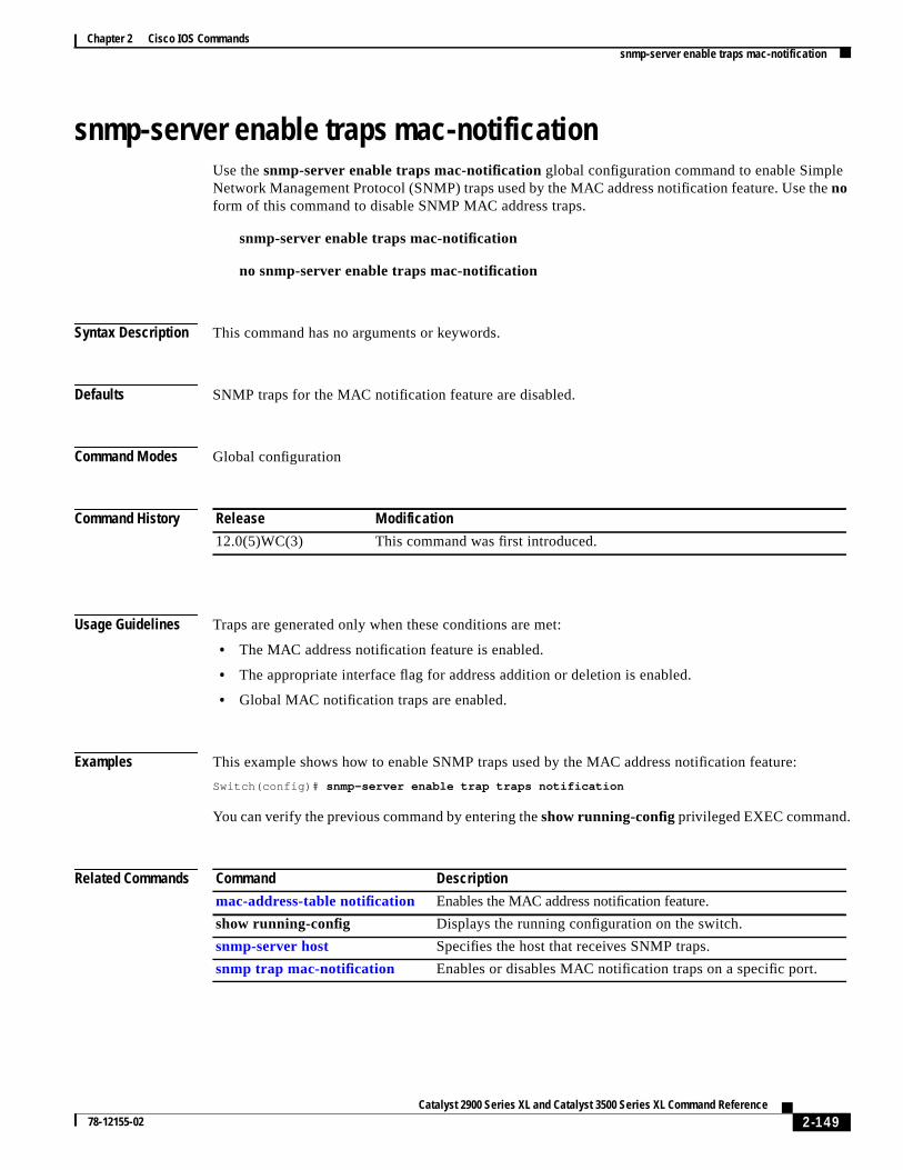
Chapter 2 Cisco IOS Commandssnmp-server enable traps mac-notification
e
snmp-server enable traps mac-notificationUse thesnmp-server enable traps mac-notificationglobal configuration command to enable SimpleNetwork Management Protocol (SNMP) traps used by the MAC address notification feature. Use thnoform of this command to disable SNMP MAC address traps.
snmp-server enable traps mac-notification
no snmp-server enable traps mac-notification
Syntax Description This command has no arguments or keywords.
Defaults SNMP traps for the MAC notification feature are disabled.
Command Modes Global configuration
Command History
Usage Guidelines Traps are generated only when these conditions are met:
• The MAC address notification feature is enabled.
• The appropriate interface flag for address addition or deletion is enabled.
• Global MAC notification traps are enabled.
Examples This example shows how to enable SNMP traps used by the MAC address notification feature:
Switch(config)# snmp-server enable trap traps notification
You can verify the previous command by entering theshow running-configprivileged EXEC command.
Related Commands
Release Modification
12.0(5)WC(3) This command was first introduced.
Command Description
mac-address-table notification Enables the MAC address notification feature.
show running-config Displays the running configuration on the switch.
snmp-server host Specifies the host that receives SNMP traps.
snmp trap mac-notification Enables or disables MAC notification traps on a specific port.
2-149Catalyst 2900 Series XL and Catalyst 3500 Series XL Command Reference
78-12155-02

Chapter 2 Cisco IOS Commandssnmp-server enable traps vlan-membership
snmp-server enable traps vlan-membershipUse thesnmp-server enable traps vlan-membershipglobal configuration command to enable SimpleNetwork Management Protocol (SNMP) notification for VLAN Membership Policy Server (VMPS)changes. Use theno form of this command to disable the VMPS trap notification.
snmp-server enable traps vlan-membership
no snmp-server enable traps vlan-membership
Syntax Description This command has no arguments or keywords.
Defaults SNMP traps for VMPS are disabled.
Command Modes Global configuration
Command History
Usage Guidelines Specify the host that receives the traps by using thesnmp-server hostglobal configuration command.
Examples This example shows how to enable VMPS to send trap notifications:
Switch(config)# snmp-server enable trap vlan-membership
You can verify the previous command by entering theshow running-configprivileged EXEC command.
Related Commands
Release Modification
11.2(8)SA4 This command was first introduced.
Command Description
show running-config Displays the running configuration on the switch.
snmp-server host Specifies the host that receives SNMP traps.
2-150Catalyst 2900 Series XL and Catalyst 3500 Series XL Command Reference
78-12155-02
Chapter 2 Cisco IOS Commandssnmp-server enable traps vtp
snmp-server enable traps vtpUse thesnmp-server enable traps vtpglobal configuration command to enable Simple NetworkManagement Protocol (SNMP) notification for VLAN Trunking Protocol (VTP) changes. Use thenoform of this command to disable VTP trap notification.
snmp-server enable traps vtp
no snmp-server enable traps vtp
Syntax Description This command has no arguments or keywords.
Defaults SNMP traps for VTP are disabled.
Command Modes Global configuration
Command History
Usage Guidelines Specify the host that receives the traps by using thesnmp-server host global configuration command.
Examples This example shows how to enable VTP to send trap notifications:
Switch(config)# snmp-server enable trap vtp
You can verify the previous command by entering theshow vtp statususer EXEC command or theshowrunning-config privileged EXEC command.
Related Commands
Release Modification
11.2(8)SA4 This command was first introduced.
Command Description
show running-config Displays the running configuration on the switch.
show vtp status Displays general information about the VTP management domain andstatus.
snmp-server host Specifies the host that receives SNMP traps.
2-151Catalyst 2900 Series XL and Catalyst 3500 Series XL Command Reference
78-12155-02
Chapter 2 Cisco IOS Commandssnmp-server host
snmp-server hostUse thesnmp-server host global configuration command to specify the host that receives SimpleNetwork Management Protocol (SNMP) traps. Use theno form of this command to remove the specifiedhost.
snmp-server hosthost-address community-string[c2900| config | snmp | tty | udp-portport-number | vlan-membership | vtp]
no snmp-server hosthost-addresscommunity-string
Syntax Description
Defaults The SNMP trap host address and community string are not defined.
Traps are disabled.
Command Modes Global configuration
Command History
Usage Guidelines Use thesnmp-server host global configuration command with thesnmp-server enable trapsglobalcommands to generate traps.
host-address IP address or name of the SNMP trap host.
community-string Password-like community string sent with the trap operation.
c2900 (Optional) Send SNMP Catalyst 2900 XL or Catalyst 3500 XL switchtraps.
config (Optional) Send SNMP configuration traps.
snmp (Optional) Send SNMP-type traps.
tty (Optional) Send Cisco enterprise-specific traps when a TransmissionControl Protocol (TCP) connection closes.
udp-port port-number (Optional) UDP port of the host to use. The default is 162.
vlan-membership (Optional) Send SNMP VLAN Membership Policy Server (VMPS) traps
vtp (Optional) Send SNMP VLAN Trunking Protocol (VTP) traps.
Release Modification
11.2(8)SA4 This command was first introduced.
2-152Catalyst 2900 Series XL and Catalyst 3500 Series XL Command Reference
78-12155-02
Chapter 2 Cisco IOS Commandssnmp-server host
Examples This example shows how to configure an SNMP host to receive VTP traps:
Switch(config)# snmp-server host 172.20.128.178 traps vtp
You can verify the previous command by entering theshow running-configprivileged EXEC command.
Related Commands Command Description
snmp-server enable traps vlan-membership Enables SNMP notification for VMPS changes.
snmp-server enable traps vtp Enables SNMP notification for VTP changes.
2-153Catalyst 2900 Series XL and Catalyst 3500 Series XL Command Reference
78-12155-02
Chapter 2 Cisco IOS Commandssnmp trap mac-notification
hen
snmp trap mac-notificationUse thesnmp trap mac-notification interface configuration command to enable or disable the MACnotification traps on a particular port. Use theno form of the command to return the port to defaultsettings.
snmp trap mac-notification [added | removed]
no snmp trap mac-notification [added | removed]
Syntax Description
Defaults The SNMP address-addition and address-removal traps are disabled.
Command Modes Interface configuration
Command History
Usage Guidelines Even though the notification trap is enabled for a particular port, the trap is actually generated only wthe global MAC trap flag is also enabled. To enable the global trap flag, use thesnmp-server enabletraps mac-notification global configuration command.
Examples This example shows how to enable an address-addition trap on a port:
Switch(config-if)# snmp trap mac-notification added
This example shows how to enable an address-removal trap on a port:
Switch(config-if)# snmp trap mac-notification removed
You can verify the previous commands by entering theshow running-config privileged EXECcommand.
Related Commands
added (Optional) Enable MAC notification traps whenever a MAC address isadded on this port.
removed (Optional) Enable MAC notification traps whenever a MAC address isremoved from this port.
Release Modification
12.0(5)WC3 This command was first introduced.
mac-address-table notification Enables the MAC notification feature on a switch.
show mac-address-table notification Displays MAC-notification parameters.
2-154Catalyst 2900 Series XL and Catalyst 3500 Series XL Command Reference
78-12155-02

Chapter 2 Cisco IOS Commandsspanning-tree
a
like
EC
1.
spanning-treeUse thespanning-tree global configuration command to enable Spanning Tree Protocol (STP) on VLAN. Use theno form of the command to disable STP on a VLAN.
spanning-tree [vlan stp-list]
no spanning-tree [vlan stp-list]
Syntax Description
Defaults STP is enabled.
Command Modes Global configuration
Command History
Usage Guidelines Disabling STP causes the VLAN or a list of VLANs to stop participating in STP. Ports that areadministratively down remain down. Received Bridge Protocol Data Units (BPDUs) are forwardedother multicast frames. The VLAN does not detect and prevent loops when STP is disabled.
You can disable STP on a VLAN that is not active and verify the change by using the privileged EXshow running-configor theshow spanning-tree vlanstp-listprivileged EXEC commands. The settingtakes effect when the VLAN is activated.
If the variablestp-list is omitted, the command applies to the STP instance associated with VLAN
You can enable STP on a VLAN that has no ports assigned to it.
Examples This example shows how to disable STP on VLAN 5:
Switch(config)# no spanning-tree vlan 5
You can verify the previous command by entering theshow spanning-treeuser EXEC command. In thisinstance, VLAN 5 does not appear in the list.
vlan stp-list (Optional) List of spanning-tree instances. Each spanning-tree instance isassociated with a VLAN ID. Valid IDs are from 1 to 1005. Enter each VLAN IDseparated by a space. Do not enter leading zeroes. Ranges are not supported.
Release Modification
11.2(8)SA3 This command was first introduced.
2-155Catalyst 2900 Series XL and Catalyst 3500 Series XL Command Reference
78-12155-02

Chapter 2 Cisco IOS Commandsspanning-tree
es
Related Commands Command Description
show spanning-tree Displays spanning-tree information for the specified spanning-treeinstances.
spanning-tree forward-time Specifies the forwarding-time for the specified spanning-treeinstances.
spanning-tree max-age Changes the interval between messages the spanning tree receivfrom the root switch.
spanning-tree port-priority Configures a port priority, which is used when two switches tie forposition as the root switch.
spanning-tree protocol Specifies the STP version to be used for specified spanning-treeinstances.
2-156Catalyst 2900 Series XL and Catalyst 3500 Series XL Command Reference
78-12155-02

Chapter 2 Cisco IOS Commandsspanning-tree cost
eecting
t path
ith
LAN
.
spanning-tree costUse the spanning-tree cost interface configuration command to set the path cost for Spanning TreProtocol (STP) calculations. In the event of a loop, spanning tree considers the path cost when selan interface to place into the forwarding state. Use theno form of this command to return to the defaultvalue.
spanning-tree [vlan stp-list] costcost
no spanning-tree [vlan stp-list] cost
Syntax Description
Defaults The default path cost is computed from the interface bandwidth setting. These are the IEEE defaulcost values:
• 10 Mbps – 100
• 100 Mbps – 19
• 155 Mbps – 14
• 1 Gbps – 4
• 10 Gbps – 2
• Speeds greater than 10 Gbps – 1
Command Modes Interface configuration
Command History
Usage Guidelines If the variablestp-list is omitted, the command applies to the spanning-tree instance associated wVLAN 1.
You can set a cost for a port or on a VLAN that does not exist. The setting takes effect when the Vexists.
Examples This example shows how to set a path cost value of 250 for VLAN 1:
Switch(config-if)# spanning-tree vlan 1 cost 250
You can verify the previous command by entering theshow spanning-treeuser EXEC command.
vlan stp-list (Optional) List of spanning-tree instances. Each spanning-tree instance isassociated with a VLAN ID. Valid IDs are from 1 to 1005. Enter each VLAN IDseparated by a space. Do not enter leading zeroes. Ranges are not supported.
cost Path cost can range from 1 to 65535, with higher values indicating higher costsThis range applies whether or not the IEEE STP has been specified.
Release Modification
11.2(8)SA3 This command was first introduced.
2-157Catalyst 2900 Series XL and Catalyst 3500 Series XL Command Reference
78-12155-02

Chapter 2 Cisco IOS Commandsspanning-tree cost
.
Related Commands Command Description
show spanning-tree Displays spanning-tree information for the specified spanning-treeinstances.
spanning-tree portfast Enables the Port Fast feature on a port in all its associated VLANs
spanning-tree priority Configures the switch priority for the specified spanning-treeinstance.
2-158Catalyst 2900 Series XL and Catalyst 3500 Series XL Command Reference
78-12155-02

Chapter 2 Cisco IOS Commandsspanning-tree forward-time
eg and
IBM
1.
fect
spanning-tree forward-timeUse thespanning-tree forward-time global configuration command to set the forwarding-time for thspecified spanning-tree instances. The forwarding time determines how long each of the listeninlearning states last before the port begins forwarding. Use theno form of this command to return to thedefault value.
spanning-tree[vlan stp-list] forward-time seconds
no spanning-tree [vlan stp-list] forward-time
Syntax Description
Defaults The default forwarding-time for IEEE Spanning Tree Protocol (STP) is 15 seconds. The default forSTP is 4 seconds.
Command Modes Global configuration
Command History
Usage Guidelines If the variablestp-list is omitted, the command applies to the STP instance associated with VLAN
You can set the forwarding-time on a VLAN that has no ports assigned to it. The setting takes efwhen you assign ports to it.
Examples This example shows how to set the spanning-tree forwarding time to 18 seconds for VLAN 20:
Switch(config)# spanning-tree vlan 20 forward-time 18
You can verify the previous command by entering theshow spanning-treeuser EXEC command.
vlan stp-list (Optional) List of spanning-tree instances. Each spanning-tree instance isassociated with a VLAN ID. Valid IDs are from 1 to 1005. Enter each VLAN IDseparated by a space. Do not enter leading zeroes. Ranges are not supported.
seconds Forward-delay interval from 4 to 200 seconds.
Release Modification
11.2(8)SA3 This command was first introduced.
2-159Catalyst 2900 Series XL and Catalyst 3500 Series XL Command Reference
78-12155-02
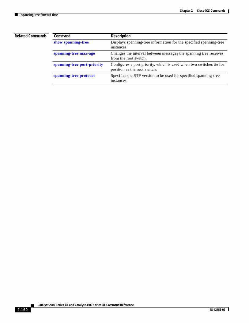
Chapter 2 Cisco IOS Commandsspanning-tree forward-time
es
Related Commands Command Description
show spanning-tree Displays spanning-tree information for the specified spanning-treeinstances.
spanning-tree max-age Changes the interval between messages the spanning tree receivfrom the root switch.
spanning-tree port-priority Configures a port priority, which is used when two switches tie forposition as the root switch.
spanning-tree protocol Specifies the STP version to be used for specified spanning-treeinstances.
2-160Catalyst 2900 Series XL and Catalyst 3500 Series XL Command Reference
78-12155-02

Chapter 2 Cisco IOS Commandsspanning-tree hello-time
lol.
1.
you
spanning-tree hello-timeUse thespanning-tree hello-timeglobal configuration command to specify the interval between helBridge Protocol Data Units (BPDUs). Use theno form of this command to return to the default interva
spanning-tree [vlan stp-list] hello-time seconds
no spanning-tree[vlan stp-list] hello-time
Syntax Description
Defaults The default hello time for IEEE Spanning Tree Protocol (STP) and IBM STP is 2 seconds.
Command Modes Global configuration
Command History
Usage Guidelines If the variablestp-list is omitted, the command applies to the STP instance associated with VLAN
You can set the hello time on a VLAN that has no ports assigned to it. The setting takes effect whenassign ports to it.
Examples This example shows how to set the spanning-tree hello-delay time to 3 seconds for VLAN 20:
Switch(config)# spanning-tree vlan 20 hello-time 3
You can verify the previous command by entering theshow spanning-treeuser EXEC command.
Related Commands
vlan stp-list (Optional) List of spanning-tree instances. Each spanning-tree instance isassociated with a VLAN ID. Valid IDs are from 1 to 1005. Enter each VLAN IDseparated by a space. Do not enter leading zeroes. Ranges are not supported.
seconds Interval from 1 to 10 seconds.
Release Modification
11.2(8)SA3 This command was first introduced.
Command Description
show spanning-tree Displays spanning-tree information for the specified spanning-treeinstances.
spanning-tree Enables STP on a VLAN.
spanning-tree port-priority Configures a port priority, which is used when two switches tie forposition as the root switch.
spanning-tree protocol Specifies the STP version to be used for specified spanning-treeinstances.
2-161Catalyst 2900 Series XL and Catalyst 3500 Series XL Command Reference
78-12155-02

Chapter 2 Cisco IOS Commandsspanning-tree max-age
gesUnitcol
1.
ou
es
spanning-tree max-ageUse thespanning-tree max-ageglobal configuration command to change the interval between messathe spanning tree receives from the root switch. If a switch does not receive a Bridge Protocol Data(BPDU) message from the root switch within this interval, it recomputes the Spanning Tree Proto(STP) topology. Use theno form of this command to return to the default interval.
spanning-tree[vlan stp-list] max-ageseconds
no spanning-tree [vlan stp-list] max-age
Syntax Description
Defaults The default max-age for IEEE STP is 20 seconds. The default for IBM STP is 10 seconds.
Command Modes Global configuration
Command History
Usage Guidelines The max-agesetting must be greater than thehello-time setting.
If the variablestp-list is omitted, the command applies to the STP instance associated with VLAN
You can set themax-ageon a VLAN that has no ports assigned to it. The setting takes effect when yassign ports to the VLAN.
Examples This example shows how to setspanning-tree max-age to 30 seconds for VLAN 20:
Switch(config)# spanning-tree vlan 20 max-age 30
This example shows how to reset themax-ageparameter to the default value for spanning-tree instanc100 through 102:
Switch(config)# no spanning-tree vlan 100 101 102 max-age
You can verify the previous commands by entering theshow spanning-treeuser EXEC command.
vlan stp-list (Optional) List of spanning-tree instances. Each spanning-tree instance isassociated with a VLAN ID. Valid IDs are from 1 to 1005. Enter each VLAN IDseparated by a space. Do not enter leading zeroes. Ranges are not supported.
seconds Interval the switch waits between receiving BPDUs from the root switch.Enter a number from 6 to 200.
Release Modification
11.2(8)SA3 This command was first introduced.
2-162Catalyst 2900 Series XL and Catalyst 3500 Series XL Command Reference
78-12155-02
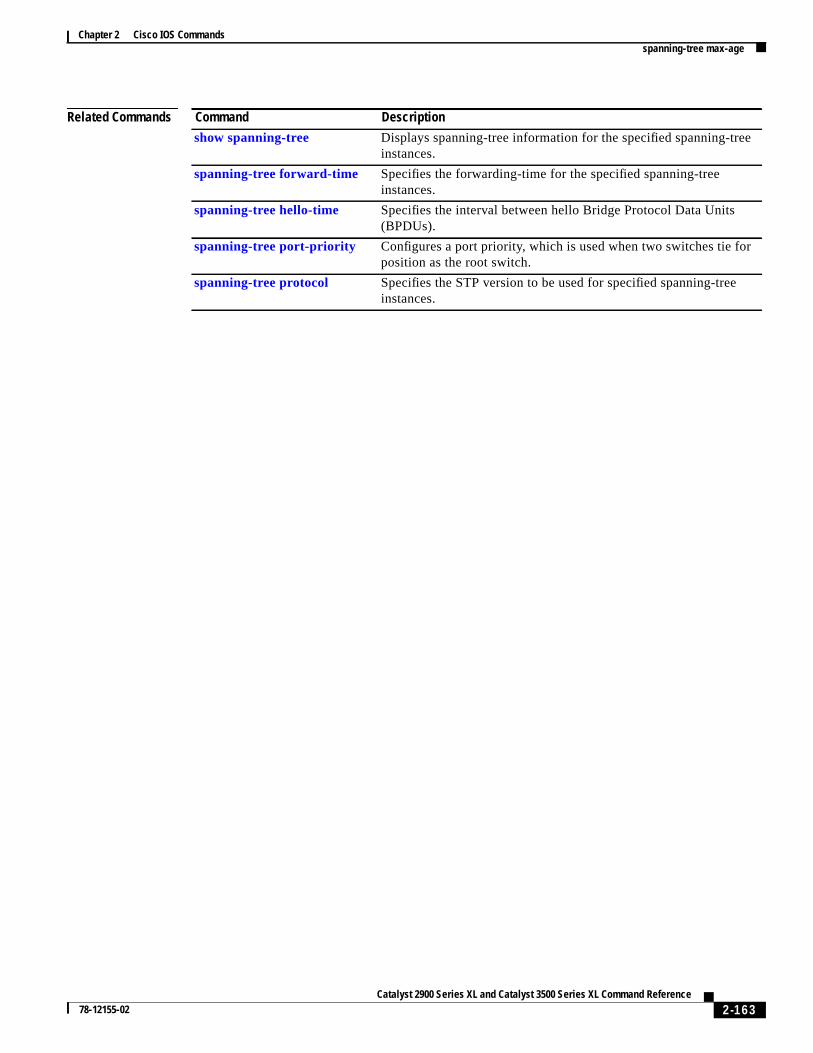
Chapter 2 Cisco IOS Commandsspanning-tree max-age
Related Commands Command Description
show spanning-tree Displays spanning-tree information for the specified spanning-treeinstances.
spanning-tree forward-time Specifies the forwarding-time for the specified spanning-treeinstances.
spanning-tree hello-time Specifies the interval between hello Bridge Protocol Data Units(BPDUs).
spanning-tree port-priority Configures a port priority, which is used when two switches tie forposition as the root switch.
spanning-tree protocol Specifies the STP version to be used for specified spanning-treeinstances.
2-163Catalyst 2900 Series XL and Catalyst 3500 Series XL Command Reference
78-12155-02
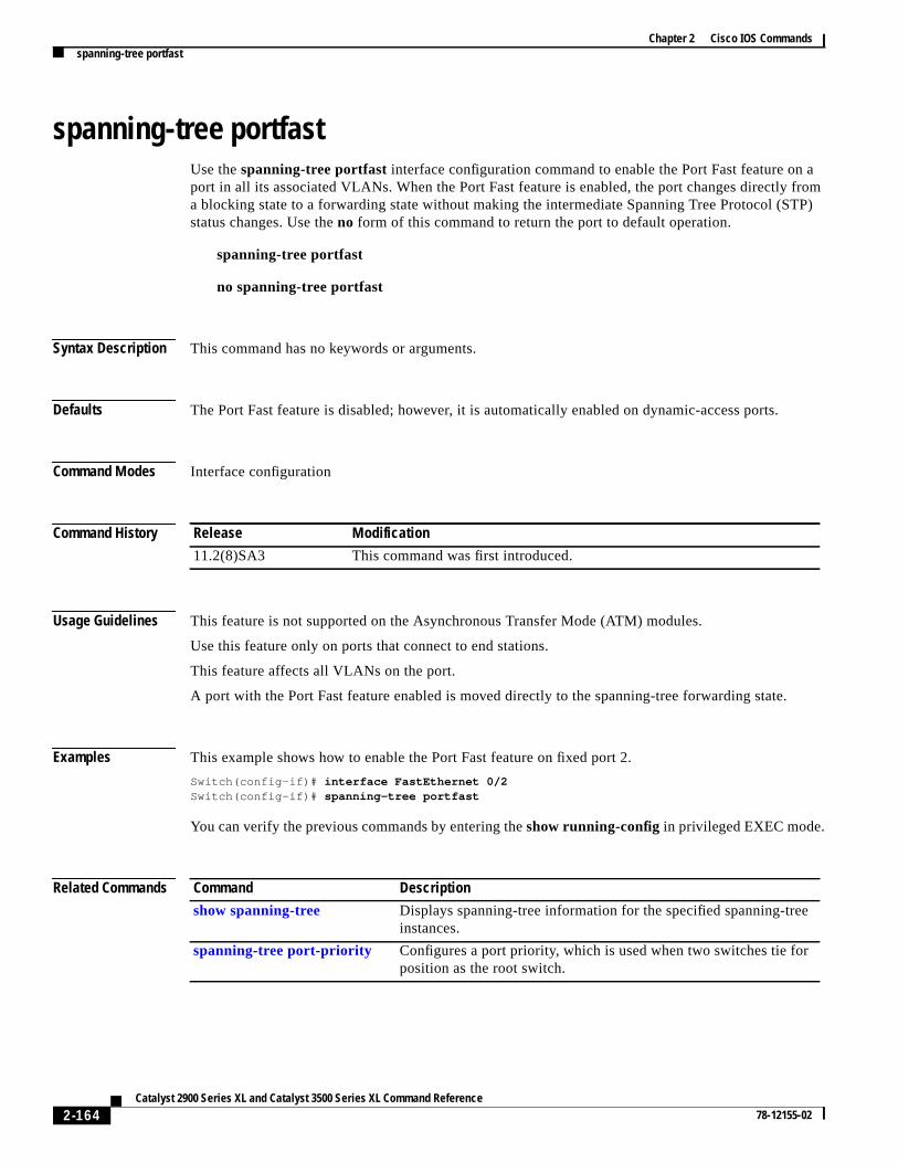
Chapter 2 Cisco IOS Commandsspanning-tree portfast
afromTP)
spanning-tree portfastUse thespanning-tree portfast interface configuration command to enable the Port Fast feature onport in all its associated VLANs. When the Port Fast feature is enabled, the port changes directlya blocking state to a forwarding state without making the intermediate Spanning Tree Protocol (Sstatus changes. Use theno form of this command to return the port to default operation.
spanning-tree portfast
no spanning-tree portfast
Syntax Description This command has no keywords or arguments.
Defaults The Port Fast feature is disabled; however, it is automatically enabled on dynamic-access ports.
Command Modes Interface configuration
Command History
Usage Guidelines This feature is not supported on the Asynchronous Transfer Mode (ATM) modules.
Use this feature only on ports that connect to end stations.
This feature affects all VLANs on the port.
A port with the Port Fast feature enabled is moved directly to the spanning-tree forwarding state.
Examples This example shows how to enable the Port Fast feature on fixed port 2.
Switch(config-if)# interface FastEthernet 0/2Switch(config-if)# spanning-tree portfast
You can verify the previous commands by entering theshow running-config in privileged EXEC mode.
Related Commands
Release Modification
11.2(8)SA3 This command was first introduced.
Command Description
show spanning-tree Displays spanning-tree information for the specified spanning-treeinstances.
spanning-tree port-priority Configures a port priority, which is used when two switches tie forposition as the root switch.
2-164Catalyst 2900 Series XL and Catalyst 3500 Series XL Command Reference
78-12155-02
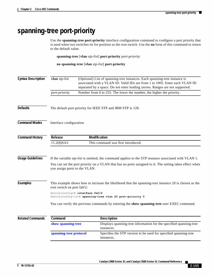
Chapter 2 Cisco IOS Commandsspanning-tree port-priority
t
1.
when
as the
spanning-tree port-priorityUse thespanning-tree port-priority interface configuration command to configure a port priority thais used when two switches tie for position as the root switch. Use theno form of this command to returnto the default value.
spanning-tree[vlan stp-list] port-priority port-priority
no spanning-tree [vlan stp-list] port-priority
Syntax Description
Defaults The default port-priority for IEEE STP and IBM STP is 128.
Command Modes Interface configuration
Command History
Usage Guidelines If the variablestp-list is omitted, the command applies to the STP instance associated with VLAN
You can set the port priority on a VLAN that has no ports assigned to it. The setting takes effect you assign ports to the VLAN.
Examples This example shows how to increase the likelihood that the spanning-tree instance 20 is chosenroot switch on port fa0/2:
Switch(config)# interface fa0/2Switch(config-if)# spanning-tree vlan 20 port-priority 0
You can verify the previous commands by entering theshow spanning-treeuser EXEC command.
Related Commands
vlan stp-list (Optional) List of spanning-tree instances. Each spanning-tree instance isassociated with a VLAN ID. Valid IDs are from 1 to 1005. Enter each VLAN IDseparated by a space. Do not enter leading zeroes. Ranges are not supported.
port-priority Number from 0 to 255. The lower the number, the higher the priority.
Release Modification
11.2(8)SA3 This command was first introduced.
Command Description
show spanning-tree Displays spanning-tree information for the specified spanning-treeinstances.
spanning-tree protocol Specifies the STP version to be used for specified spanning-treeinstances.
2-165Catalyst 2900 Series XL and Catalyst 3500 Series XL Command Reference
78-12155-02
Chapter 2 Cisco IOS Commandsspanning-tree priority
eoot
1.
ffect
spanning-tree priorityUse thespanning-tree priority global configuration command to configure the switch priority for thspecified spanning-tree instance. This changes the likelihood that the switch is selected as the rswitch. Use theno form of this command to revert to the default value.
spanning-tree [vlan stp-list] priority bridge-priority
no spanning-tree [vlan stp-list] priority
Syntax Description
Defaults The default bridge priority for IEEE STP and IBM STP is 32768.
Command Modes Global configuration
Command History
Usage Guidelines If the variablestp-list is omitted, the command applies to the STP instance associated with VLAN
You can configure the switch priority on a VLAN that has no ports assigned to it. The setting takes ewhen you assign ports to the VLAN.
Examples This example shows how to set the spanning-tree priority to 125 for a list of VLANs:
Switch(config)# spanning-tree vlan 20 100 101 102 priority 125
You can verify the previous command by entering theshow spanning-treeuser EXEC command.
vlan stp-list (Optional) List of spanning-tree instances. Each spanning-tree instance isassociated with a VLAN ID. Valid IDs are from 1 to 1005. Enter each VLAN IDseparated by a space. Do not enter leading zeroes. Ranges are not supported.
bridge-priority A number from 0 to 65535. The lower the number, the more likely the switch willbe chosen as root.
Release Modification
11.2(8)SA3 This command was first introduced.
2-166Catalyst 2900 Series XL and Catalyst 3500 Series XL Command Reference
78-12155-02

Chapter 2 Cisco IOS Commandsspanning-tree priority
es
Related Commands Command Description
show spanning-tree Displays spanning-tree information for the specified spanning-treeinstances.
spanning-tree forward-time Specifies the forwarding-time for the specified spanning-treeinstances.
spanning-tree hello-time Specifies the interval between hello Bridge Protocol Data Units(BPDUs).
spanning-tree max-age Changes the interval between messages the spanning tree receivfrom the root switch.
spanning-tree protocol Specifies the STP version to be used for specified spanning-treeinstances.
2-167Catalyst 2900 Series XL and Catalyst 3500 Series XL Command Reference
78-12155-02

Chapter 2 Cisco IOS Commandsspanning-tree protocol
ol
e
ith
when
ted.
spanning-tree protocolUse thespanning-tree protocol global configuration command to specify the Spanning Tree Protoc(STP) to be used for specified spanning-tree instances. Use theno form of this command to use thedefault protocol.
spanning-tree [vlan stp-list] protocol { ieee | ibm}
no spanning-tree [vlan stp-list] protocol
Syntax Description
Defaults The default protocol isieee.
Command Modes Global configuration
Command History
Usage Guidelines Changing thespanning-tree protocolcommand changes spanning-tree parameters to change to thdefault values of the new protocol.
If the variablestp-list is omitted, this command applies to the spanning-tree instance associated wVLAN 1.
You can change the protocol on a VLAN that has no ports assigned to it. The setting takes effectyou assign ports to it.
Examples This example shows how to change the STP version for VLAN 20 to the IBM version of STP:
Switch(config)# spanning-tree vlan 20 protocol ibm
You can verify the previous command by entering theshow spanning-treeuser EXEC command.
vlan stp-list (Optional) List of spanning-tree instances. Each spanning-tree instance isassociated with a VLAN ID. Valid IDs are from 1 to 1005. Enter each VLANID separated by a space. Do not enter leading zeroes. Ranges are not suppor
ieee IEEE Ethernet STP.
ibm IBM STP.
Release Modification
11.2(8)SA3 This command was first introduced.
2-168Catalyst 2900 Series XL and Catalyst 3500 Series XL Command Reference
78-12155-02

Chapter 2 Cisco IOS Commandsspanning-tree protocol
Related Commands Command Description
show spanning-tree Displays spanning-tree information for the specified spanning-treeinstances.
spanning-tree Enables STP on a VLAN.
spanning-tree forward-time Specifies the forwarding-time for the specified spanning-treeinstances.
spanning-tree max-age Changes the interval between messages that the spanning treereceives from the root switch.
spanning-tree port-priority Configures a port priority, that is used when two switches tie forposition as the root switch.
2-169Catalyst 2900 Series XL and Catalyst 3500 Series XL Command Reference
78-12155-02
Chapter 2 Cisco IOS Commandsspanning-tree rootguard
forthes the
as theitch
llally
, theguardistent
face
spanning-tree rootguardUse thespanning-tree rootguard interface configuration command to enable the root guard featureall the VLANs associated with the selected port. Root guard restricts which port is allowed to be Spanning Tree Protocol (STP) root port or the path-to-the root for the switch. The root port providebest path from the switch to the root switch. Use theno form of this command to disable this feature.
spanning-tree rootguard
no spanning-tree rootguard
Syntax Description This command has no keywords or arguments.
Defaults The root guard feature is disabled.
Command Modes Interface configuration
Command History
Usage Guidelines When the root guard feature is enabled, if spanning-tree calculations cause a port to be selectedroot port, the port transitions to the root-inconsistent (blocked) state to prevent the customer’s swfrom becoming the root switch or being in the path to the root.
When theno spanning-tree rootguard command is entered, the root guard feature is disabled for aVLANs on the selected port. If this port is in the root-inconsistent (blocked) state, the port automatictransitions to the listening state.
Do not enable the root guard on ports that will be used by the UplinkFast feature. With UplinkFastbackup ports (in the blocked state) replace the root port in the case of a failure. However, if root is also enabled, all the backup ports used by the UplinkFast feature are placed in the root-inconsstate (blocked) and prevented from reaching the forwarding state.
Examples This example shows how to enable the root guard feature on all the VLANs associated with interfa0/3:
Switch(config)# interface fa0/3Switch(config-if)# spanning-tree rootguard
You can verify the previous commands by entering theshow running-config privileged EXECcommand.
Release Modification
12.0(5)XU This command was first introduced.
2-170Catalyst 2900 Series XL and Catalyst 3500 Series XL Command Reference
78-12155-02

Chapter 2 Cisco IOS Commandsspanning-tree rootguard
,to
e
Related Commands Command Description
show running-config Displays the current operating configuration.
show spanning-tree Displays spanning-tree information for the specified spanning-treeinstances.
spanning-tree cost Specifies the path cost for STP calculations. In the event of a loopspanning tree considers the path cost when selecting an interfaceplace into the forwarding state.
spanning-tree port-priority Configures a port priority that is used when two switches tie forposition as the root switch.
spanning-tree priority Configures the switch priority for the specified spanning-treeinstance and affects the likelihood that the switch is selected as throot switch.
2-171Catalyst 2900 Series XL and Catalyst 3500 Series XL Command Reference
78-12155-02

Chapter 2 Cisco IOS Commandsspanning-tree stack-port
st or
tackernet
ve ane.
spanning-tree stack-portUse thespanning-tree stack-portinterface configuration command to enable cross-stack UplinkFa(CSUF) on an interface and to accelerate the choice of a new root port when a link or switch failswhen Spanning Tree Protocol (STP) reconfigures itself. Use theno form of this command to return tothe default setting.
spanning-tree stack-port
no spanning-tree stack-port
Syntax Description This command has no arguments or keywords.
Defaults CSUF is disabled on all interfaces.
Command Modes Interface configuration
Command History
Usage Guidelines This command is effective only if you enable the UplinkFast feature by using thespanning-treeuplinkfast global configuration command.
Use this command only on access switches.
You can enable CSUF only on one stack-port Gigabit Interface Converter (GBIC) interface. The sport connects to the GigaStack GBIC multidrop backbone. If you try to enable CSUF on a Fast Ethor a copper-based Gigabit Ethernet port, you receive an error message.
If CSUF is already enabled on an interface and you try to enable it on another interface, you receierror message. You must disable CSUF on the first interface before enabling it on a new interfac
Examples The following command shows how to enable CSUF on the GBIC interface gi0/1:
Switch(config)# interface gi0/1Switch(config-if)# spanning-tree stack-port
You can verify the previous command by entering theshow spanning-tree user EXEC command.
Related Commands
Release Modification
12.0(5)XW This command was first introduced.
Command Description
show spanning-tree Displays spanning-tree information for the specifiedspanning-tree instances.
2-172Catalyst 2900 Series XL and Catalyst 3500 Series XL Command Reference
78-12155-02

Chapter 2 Cisco IOS Commandsspanning-tree uplinkfast
ote
ual
f allll
ault
, theguardistent
s
spanning-tree uplinkfastUse thespanning-tree uplinkfast global configuration command to accelerate the choice of a new roport when a link or switch fails or when Spanning Tree Protocol (STP) reconfigures itself. Use thnoform of this command to return to the default value.
spanning-tree uplinkfast [max-update-ratepkts-per-second]
no spanning-tree uplinkfast[max-update-ratepkts-per-second]
Syntax Description
Defaults UplinkFast is disabled.
Command Modes Global configuration
Command History
Usage Guidelines When you enable UplinkFast, it is enabled for the entire switch and cannot be enabled for individVLANs.
When you enable UplinkFast, the bridge priority of all VLANs is set to 49152, and the path cost oports and VLAN trunks is increased by 3000. This change reduces the chance that the switch wibecome the root switch.
When you disable UplinkFast, the bridge priorities of all VLANs and path costs are set to their defvalues.
Do not enable the root guard on ports that will be used by the UplinkFast feature. With UplinkFastbackup ports (in the blocked state) replace the root port in the case of a failure. However, if root is also enabled, all the backup ports used by the UplinkFast feature are placed in the root-inconsstate (blocked) and prevented from reaching the forwarding state.
max-update-ratepkts-per-second The number of packets per second at which stations addresupdate packets are sent. The range is 0 to 1000.
Release Modification
11.2(8)SA6 This command was first introduced.
2-173Catalyst 2900 Series XL and Catalyst 3500 Series XL Command Reference
78-12155-02

Chapter 2 Cisco IOS Commandsspanning-tree uplinkfast
Examples The following command shows how to enable UplinkFast:
Switch(config)# spanning-tree uplinkfast
You can verify the previous command by entering theshow spanning-tree user EXEC command.
Related Commands Command Description
show spanning-tree Displays spanning-tree information for the specified spanning-treeinstances.
2-174Catalyst 2900 Series XL and Catalyst 3500 Series XL Command Reference
78-12155-02

Chapter 2 Cisco IOS Commandsspeed
e
peed
speedUse thespeedinterface configuration command to specify the speed of a Fast Ethernet port. Use thnoform of this command to return the port to its default value.
speed{ 10 | 100 | auto}
no speed
Syntax Description
Defaults For Fast Ethernet ports, the default isauto.
For Gigabit Ethernet ports, the speed is 1000 Mbps and is not configurable.
For Asynchronous Transfer Mode (ATM) ports, the speed is 155 Mbps and is not configurable.
Command Modes Interface configuration
Command History
Usage Guidelines Certain ports can be configured to be either 10 or 100 Mbps. Applicability of this command ishardware-dependent.
If the speed is set to auto, the switch negotiates with the device at the other end of the link for the ssetting and then forces the speed setting to the negotiated value. The duplex setting remains asconfigured on each end of the link, which could result in a duplex setting mismatch.
If both the speed and duplex are set to specific values, autonegotiation is disabled.
Note For guidelines on setting the switch speed and duplex parameters, see theCatalyst 2900 Series XLand Catalyst 3500 Series XL Software Configuration Guide.
10 Port runs at 10 Mbps.
100 Port runs at 100 Mbps.
auto Port automatically detects whether it should run at 10 or 100 Mbps onFast Ethernet ports.
Release Modification
11.2(8)SA This command was first introduced.
2-175Catalyst 2900 Series XL and Catalyst 3500 Series XL Command Reference
78-12155-02

Chapter 2 Cisco IOS Commandsspeed
Examples This example shows how to set port 1 on module 2 to 100 Mbps:
Switch(config)# interface fastethernet2/1Switch(config-if)# speed 100
You can verify the previous commands by entering theshow running-config in privileged EXEC mode.
Related Commands Command Description
duplex Specifies the duplex mode of operation for Fast Ethernet and GigabitEthernet ports.
2-176Catalyst 2900 Series XL and Catalyst 3500 Series XL Command Reference
78-12155-02

Chapter 2 Cisco IOS Commandsswitchport access
orVLAN.ttch.
e
1.
uchMPS
s (that
s)ed
switchport accessUse theswitchport access interface configuration command to configure a port as a static-access dynamic-access port. If the mode is set to access, the port operates as a member of the configuredIf set to dynamic, the port starts discovery of VLAN assignment based on the incoming packets ireceives. Use theno form of this command to reset the access mode to the default VLAN for the swi
switchport access vlan{ vlan-id | dynamic}
no switchport access vlan{ vlan-id | dynamic}
Syntax Description
Defaults All ports are in static-access mode in VLAN 1.
A dynamic-access port is initially a member of no VLAN and receives its assignment based on thpackets it receives.
Command Modes Interface configuration
Command History
Usage Guidelines The port must be in access mode before theswitchport access vlanvlan-id or switchport access vlandynamic command can take effect. For more information, see the“switchport mode” section onpage 2-179.
An access port can be assigned to only one VLAN.
When theno switchport access vlanform is used, the access mode is reset to static access on VLAN
The following restrictions apply to dynamic-access ports:
• The software implements the VLAN Query Protocol (VQP) client, which can query a VMPS sas a Catalyst 5000 series switch. Catalyst 2900 XL and Catalyst 3500 XL switches are not Vservers. The VMPS server must be configured before a port is configured as dynamic.
• Use dynamic-access ports only to connect end stations. Connecting them to switches or routeruse bridging protocols) can cause a loss of connectivity.
vlan vlan-id ID of the VLAN. Valid IDs are from 1 to 1001. Do not enter leading zeroes.
dynamic Port is assigned to a VLAN based on the source MAC address of a host (or hostconnected to that port. The switch sends every new source MAC address receivto the VLAN Membership Policy Server (VMPS) to obtain the VLAN name towhich the dynamic-access port should be assigned. If the port already has aVLAN assigned and the source has already been approved by the VMPS, theswitch forwards the packet to the VLAN.
Release Modification
11.2(8)SA3 This command was first introduced.
11.2(8)SA4 Thedynamic keyword was added.
2-177Catalyst 2900 Series XL and Catalyst 3500 Series XL Command Reference
78-12155-02
Chapter 2 Cisco IOS Commandsswitchport access
state.
her
r
ult
• Configure the network so that STP does not put the dynamic-access port into an STP blockingThe Port Fast feature is automatically enabled on dynamic-access ports.
• Dynamic-access ports can only be in one VLAN and do not use VLAN tagging.
• Dynamic-access ports cannot be configured as:
– The source or destination port in a static address entry.
– A network port (dynamic-access ports can be assigned to a VLAN in which one of the otports is a network port).
– A port group (dynamic-access ports cannot be grouped with any other port including othedynamic ports).
– A secure port.
– A port with a secure address.
– A monitor port.
Examples This example shows how to assign a port already in access mode to VLAN 2 (instead of the defaVLAN 1):
Switch(config-if)# switchport access vlan 2
This example shows how to assign a port already in access mode to dynamic:
Switch(config-if)# switchport access vlan dynamic
This example shows how to reconfigure a dynamic-access port to a static-access port:
Switch(config-if)# no switchport access vlan dynamic
You can verify the previous commands by entering theshow interfaceinterface-idswitchportcommand in privileged EXEC mode and examining information in the Administrative Mode andOperational Mode rows.
Related Commands Command Description
switchport mode Configures the VLAN membership mode of a port.
switchport multi Configures a list of VLANs to which the port is associated.
2-178Catalyst 2900 Series XL and Catalyst 3500 Series XL Command Reference
78-12155-02

Chapter 2 Cisco IOS Commandsswitchport mode
eice.
ing
Ne new
the
t
s
switchport modeUse theswitchport mode interface configuration command to configure the VLAN membership modof a port. Use theno form of this command to reset the mode to the appropriate default for the dev
switchport mode { access | multi | trunk }
no switchport mode{ access | multi | trunk }
Syntax Description
Defaults All ports are static-access ports in VLAN 1.
Command Modes Interface configuration
Command History
Usage Guidelines Theaccess, multi , or trunk keywords take effect only when you change the port to the correspondmode by using theswitchport mode command. The static-access, multi-VLAN, and trunkconfigurations are saved, but only one configuration is active at a time.
Theno switchport mode form resets the mode to static access.
Only these combinations of port modes can appear on a single switch:
• Multi-VLAN and access ports
• Trunk and access ports
Trunk and multi-VLAN ports cannot coexist on the same switch. If you want to change a multi-VLAor trunk port into another mode, you must first change it to an access port and then reassign it to thmode.
access Set the port to access mode (either static-access or dynamic-access depending onsetting of theswitchport access vlancommand). The port operates as a nontrunking,single VLAN interface that transmits and receives nonencapsulated frames. Anaccess port can be assigned to only one VLAN.
multi Set the port to multi-VLAN port mode. The port operates as a nontrunking VLANinterface that transmits and receives nonencapsulated frames. A multi-VLAN porcan be assigned to one or more VLANs.
trunk Set the port to a trunking VLAN Layer 2 interface. The port transmits and receiveencapsulated (tagged) frames that identify the VLAN of origination. A trunk is apoint-to-point link between two switches or between a switch and a router.
Release Modification
11.2(8)SA3 This command was first introduced.
11.2(8)SA4 Thetrunk keyword was added.
2-179Catalyst 2900 Series XL and Catalyst 3500 Series XL Command Reference
78-12155-02

Chapter 2 Cisco IOS Commandsswitchport mode
Examples This example shows how to configure a port for access mode:
Switch(config-if)# switchport mode access
This example shows how to configure a port for multi-VLAN mode:
Switch(config-if)# switchport mode multi
This example shows how to configure a port for trunk mode:
Switch(config-if)# switchport mode trunk
You can verify the previous commands by entering theshow interfaceinterface-idswitchportcommand in privileged EXEC mode and examining information in the Administrative Mode andOperational Mode rows.
Related Commands Command Description
switchport access Configures a port as a static-access or dynamic-access port.
switchport multi Configures a list of VLANs to which the port is associated.
2-180Catalyst 2900 Series XL and Catalyst 3500 Series XL Command Reference
78-12155-02

Chapter 2 Cisco IOS Commandsswitchport multi
e. Use
nate
o
o
switchport multiUse theswitchport multi interface configuration command to configure a list of VLANs to which thport is associated. If the mode is set to multi, the port operates as a member of all VLANs in the listtheno form of this command to reconfigure the port as an access port.
switchport multi vlan { add vlan-list | remove vlan-list}
no switchport multi vlan
Syntax Description
Defaults The default for VLAN membership of a multi-VLAN port is VLAN 1.
Command Modes Interface configuration
Command History
Usage Guidelines Theswitchport mode multi command must be entered before theswitchport multi vlan vlan-listcommand can take effect.
In the variablevlan-list, separate nonconsecutive VLAN IDs with a comma; use a hyphen to desiga range of IDs.
A multi-VLAN port cannot be a secure port or a monitor port.
A multi-VLAN port cannot coexist with a trunk port on the same switch.
Caution To avoid loss of connectivity, do not connect multi-VLAN ports to hubs or switches. Connectmulti-VLAN ports to routers or servers.
vlan Indicate the VLAN to which the port is associated.
add vlan-list List of VLAN IDs to add. Valid IDs are from 1 to 1001. Separatenonconsecutive VLAN IDs with a comma and no spaces; use a hyphen tdesignate a range of IDs. Do not enter leading zeroes.
removevlan-list List of VLAN IDs to remove. Valid IDs are from 1 to 1001. Separatenonconsecutive VLAN IDs with a comma and no spaces; use a hyphen tdesignate a range of IDs. Do not enter leading zeroes.
Release Modification
11.2(8)SA3 This command was first introduced.
2-181Catalyst 2900 Series XL and Catalyst 3500 Series XL Command Reference
78-12155-02

Chapter 2 Cisco IOS Commandsswitchport multi
:
):
Examples This example shows how to assign a multi-VLAN port already in multimode to two VLANs:
Switch(config-if)# switchport multi vlan 2,4
This example shows how to assign a multi-VLAN port already in multimode to a range of VLANs
Switch(config-if)# switchport multi vlan 5-10
This example shows how to reset the VLAN list of a multi-VLAN port to the default (VLAN 1 only
Switch(config-if)# no switchport multi vlan
You can verify the previous commands by entering theshow interfaceinterface-idswitchportcommand in privileged EXEC mode and examining information in the Administrative Mode andOperational Mode rows.
Related Commands Command Description
switchport access Configures a port as a static-access or dynamic-access port.
switchport mode Configures the VLAN membership mode of a port.
2-182Catalyst 2900 Series XL and Catalyst 3500 Series XL Command Reference
78-12155-02

Chapter 2 Cisco IOS Commandsswitchport priority
t. Use
.
unkes.ill
switchport priorityUse theswitchport priority interface configuration command to set a port priority for the incominguntagged frames or the priority of frames received by the appliance connected to the specified portheno form of this command to return the setting to its default.
switchport priority {default default-priority-id |extend {cosvalue| none | trust } | override}
no switchport priority { default default-priority-id | extend | override}
Syntax Description
Defaults The port priority is not set, and the default value for untagged frames received on the port is zero
The appliance connected to the port is not instructed (none) what to do with the priority.
Command Modes Interface configuration
Command History
Usage Guidelines The default port priority applies if the incoming frame is an untagged frame received from a VLAN tror static-access port. This port priority does not apply to the ISL or IEEE 802.1Q VLAN tagged framIf the incoming frame is an IEEE 802.1Q VLAN tagged frame, the IEEE 802.1P User Priority bits wbe used.
Thecos keyword only applies to the 3524-PWR and 3548 XL switches.
default-priority-id The priority number for untagged traffic. The priority is a number from0 to 7. Seven is the highest priority.
extend Set the 802.1P priority of the switch.
• cosvalue—Override the 802.1p priority of devices connected to theswitch. The cos value is a number from 0 to 7. Seven is the highestpriority. Thecos keyword only applies to the 3524-PWR and the3548 XL switches.
• none—The switch is not instructed what to do with the priority.
• trust—Specify that the switch should trust (honor) the received 802.1Ppriority from devices connected to it.
override Override the priority of tagged frames with the default value.
Release Modification
12.0(5)XP This command was first introduced.
12.0(5)XU Theextend keyword and its options were added.
2-183Catalyst 2900 Series XL and Catalyst 3500 Series XL Command Reference
78-12155-02

Chapter 2 Cisco IOS Commandsswitchport priority
eived
Examples This example shows how to set a default priority on port 3.
Switch(config)# interface fa0/3Switch(config-if)# switchport priority default 7
All untagged frames received from this port will have the same priority value. You can verify theprevious commands by entering theshow interfaceinterface-idswitchport privileged EXEC command.
This example shows how to configure the appliance connected to the specified port to honor the rec802.1P priority:
Switch(config-if)# switchport priority extend trust
You can verify the previous command by entering theshow interfaceinterface-idswitchport privilegedEXEC command.
Related Commands Command Description
power inline Determines how inline power is applied to the specified port on the3524-PWR-XL switch.
show interface Displays the administrative and operational status of a switching(nonrouting) port.
switchport access Configures a port as a static-access or dynamic-access port.
switchport mode Configures the VLAN membership mode of a port.
switchport voice vlan Configures the voice VLAN on the port.
2-184Catalyst 2900 Series XL and Catalyst 3500 Series XL Command Reference
78-12155-02
Chapter 2 Cisco IOS Commandsswitchport trunk allowed vlan
nate
LAN
Ns
o
t
o
switchport trunk allowed vlanUse theswitchport trunk allowed vlan interface configuration command to control which VLANs canreceive and transmit traffic on the trunk. Use theno form of this command to reset the allowed list to thedefault value.
switchport trunk allowed vlan { add vlan-list | all | except vlan-list | remove vlan-list}
no switchport trunk allowed vlan
Syntax Description
Defaults All VLANs are included in the allowed list.
Command Modes Interface configuration
Command History
Usage Guidelines When you use theno switchport trunk allowed vlan form, the allowed list resets to the default list,which includes all VLANs.
In the variablevlan-list, separate nonconsecutive VLAN IDs with a comma; use a hyphen to desiga range of IDs. You cannot remove VLANs 1 or 1002 to 1005 from the list.
A trunk port cannot be a secure port or a monitor port. However, a static-access port can monitor a Von a trunk port. The VLAN monitored is the one associated with the static-access port.
If a trunk port is identified as a network port, the trunk port becomes the network port for all the VLAassociated with the port.
add vlan-list List of VLAN IDs to add. Valid IDs are from 1 to 1001. Separatenonconsecutive VLAN IDs with a comma and no spaces; use a hyphen tdesignate a range of IDs. Do not enter leading zeroes.
all Add all VLAN IDs to the list.
except vlan-list List of exception VLAN IDs. VLANs are added except the ones specified.Valid IDs are from 1 to 1001. Separate nonconsecutive VLAN IDs with acomma and no spaces; use a hyphen to designate a range of IDs. Do noenter leading zeroes.
remove vlan-list List of VLAN IDs to remove. Valid IDs are from 1 to 1001. Separatenonconsecutive VLAN IDs with a comma and no spaces; use a hyphen tdesignate a range of IDs. Do not enter leading zeroes.
Release Modification
11.2(8)SA4 This command was first introduced.
2-185Catalyst 2900 Series XL and Catalyst 3500 Series XL Command Reference
78-12155-02

Chapter 2 Cisco IOS Commandsswitchport trunk allowed vlan
Examples This example shows how to add VLANs 1, 2, 5, and 6 to the allowed list:
Switch(config-if)# switchport trunk allowed vlan add 1,2,5,6
You can verify the previous command by entering theshow interfaceinterface-idswitchport privilegedEXEC command.
Related Commands Command Description
switchport mode Configures the VLAN membership mode of a port.
switchport trunk encapsulation Specifies the encapsulation format on the trunk port.
switchport trunk native Specifies the native VLAN for untagged traffic when in 802.1Qtrunking mode.
2-186Catalyst 2900 Series XL and Catalyst 3500 Series XL Command Reference
78-12155-02

Chapter 2 Cisco IOS Commandsswitchport trunk encapsulation
ntrunks a
ts.
switchport trunk encapsulationUse theswitchport trunk encapsulation interface configuration command to set the encapsulationformat on the trunk port. Use theno form of this command to reset the format to the default.
switchport trunk encapsulation { isl | dot1q}
no switchport trunk encapsulation
Syntax Description
Defaults The default encapsulation format is ISL.
Command Modes Interface configuration
Command History
Usage Guidelines You cannot configure one end of the trunk as an 802.1Q trunk and the other end as an ISL or noport. However, you can configure one port as an ISL trunk and another port on the same switch a802.1Q trunk.
This command is only applicable on switch platforms and port hardware that support both forma
isl Set the encapsulation format to Inter-Switch Link (ISL). The switch encapsulates allreceived and transmitted packets with an ISL header. The switch filters native framesreceived from an ISL trunk port.
dot1q Set the tagging format to IEEE 802.1Q. With this format, the switch supportssimultaneous tagged and untagged traffic on a port.
Release Modification
11.2(8)SA4 This command was first introduced.
11.2(8)SA5 Thedot1q keyword was added.
2-187Catalyst 2900 Series XL and Catalyst 3500 Series XL Command Reference
78-12155-02

Chapter 2 Cisco IOS Commandsswitchport trunk encapsulation
Examples This example shows how to configure the encapsulation format to 802.1Q:
Switch(config-if)# switchport trunk encapsulation dot1q
You can verify the previous command by entering theshow interfaceinterface-idswitchport privilegedEXEC command.
Related Commands Command Description
switchport mode Configures the VLAN membership mode of a port.
switchport trunk allowed vlan Controls which VLANs can receive and transmit traffic on thetrunk.
switchport trunk native Specifies the native VLAN for untagged traffic when in 802.1Qtrunking mode.
2-188Catalyst 2900 Series XL and Catalyst 3500 Series XL Command Reference
78-12155-02
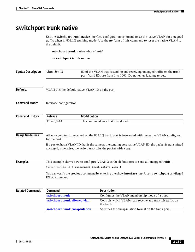
Chapter 2 Cisco IOS Commandsswitchport trunk native
d
ed
itted
switchport trunk nativeUse theswitchport trunk native interface configuration command to set the native VLAN for untaggetraffic when in 802.1Q trunking mode. Use theno form of this command to reset the native VLAN tothe default.
switchport trunk native vlan vlan-id
no switchport trunk native
Syntax Description
Defaults VLAN 1 is the default native VLAN ID on the port.
Command Modes Interface configuration
Command History
Usage Guidelines All untagged traffic received on the 802.1Q trunk port is forwarded with the native VLAN configurfor the port.
If a packet has a VLAN ID that is the same as the sending port native VLAN ID, the packet is transmuntagged; otherwise, the switch transmits the packet with a tag.
Examples This example shows how to configure VLAN 3 as the default port to send all untagged traffic:
Switch(config-if)# switchport trunk native vlan 3
You can verify the previous command by entering theshow interfaceinterface-idswitchport privilegedEXEC command.
Related Commands
vlan vlan-id ID of the VLAN that is sending and receiving untagged traffic on the trunkport. Valid IDs are from 1 to 1001. Do not enter leading zeroes.
Release Modification
11.2(8)SA4 This command was first introduced.
Command Description
switchport mode Configures the VLAN membership mode of a port.
switchport trunk allowed vlan Controls which VLANs can receive and transmit traffic onthe trunk.
switchport trunk encapsulation Specifies the encapsulation format on the trunk port.
2-189Catalyst 2900 Series XL and Catalyst 3500 Series XL Command Reference
78-12155-02

Chapter 2 Cisco IOS Commandsswitchport trunk pruning
o
t
o
switchport trunk pruningUse theswitchport trunk pruning interface configuration command to configure the VLANpruning-eligible list for ports in trunking mode. Use theno form of this command to return the pruninglist to the default setting.
switchport trunk pruning vlan { add vlan-list | all | except vlan-list | remove vlan-list}
no switchport trunk pruning
Syntax Description
Defaults VLANs 2 through 1001 are pruning eligible.
Command Modes Interface configuration
Command History
Usage Guidelines The pruning-eligible list applies only to trunk ports.
Each trunk port has its own eligibility list.
If you do not want a VLAN to be pruned, remove it from the pruning-eligible list. VLANs that arepruning-ineligible receive flooded traffic.
Examples This example shows how to remove VLANs 3 and 10 to 15 from the pruning-eligible list:
Switch(config-if)# switchport trunk pruning vlan remove 3,10-15
You can verify the previous command by entering theshow interfaceinterface-idswitchport privilegedEXEC command.
add vlan-list List of VLAN IDs to add. Valid IDs are from 2 to 1001. Separatenonconsecutive VLAN IDs with a comma and no spaces; use a hyphen tdesignate a range of IDs. Do not enter leading zeroes.
all Add all VLAN IDs to the list.
exceptvlan-list List of exception VLAN IDs (VLANs are added except the specified ones).Valid IDs are from 2 to 1001. Separate nonconsecutive VLAN IDs with acomma and no spaces; use a hyphen to designate a range of IDs. Do noenter leading zeroes.
removevlan-list List of VLAN IDs to remove. Valid IDs are from 2 to 1001. Separatenonconsecutive VLAN IDs with a comma and no spaces; use a hyphen tdesignate a range of IDs. Do not enter leading zeroes.
no Set the pruning list to the default.
Release Modification
12.0(5)XU This command was first introduced.
2-190Catalyst 2900 Series XL and Catalyst 3500 Series XL Command Reference
78-12155-02
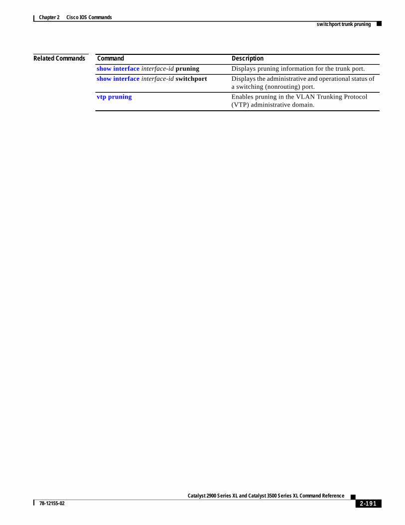
Chapter 2 Cisco IOS Commandsswitchport trunk pruning
Related Commands Command Description
show interfaceinterface-id pruning Displays pruning information for the trunk port.
show interfaceinterface-id switchport Displays the administrative and operational status ofa switching (nonrouting) port.
vtp pruning Enables pruning in the VLAN Trunking Protocol(VTP) administrative domain.
2-191Catalyst 2900 Series XL and Catalyst 3500 Series XL Command Reference
78-12155-02

Chapter 2 Cisco IOS Commandsswitchport voice vlan
ith a
rt
switchport voice vlanUse theswitchport voice vlan interface configuration command to configure the voice VLAN on theport. Use theno form of this command to return the setting to its default.
switchport voice vlan {vlan-id | dot1p | none | untagged}
no switchport voice vlan
Syntax Description
Defaults The switch default is not to automatically configure the telephone (none).
The telephone default is not to tag frames.
Command Modes Interface configuration
Command History
Usage Guidelines Ports that are not configured as trunk ports but have a configured voice VLAN are access ports wvoice VLAN ID (VVID).
vlan-id VLAN used for voice traffic. Valid IDs are from 1 to 1001 (IDs 1002 to 4094are not supported on Catalyst 2900 XL and Catalyst 3500 XL switches). Donot enter leading zeroes. The switch port is an 802.1Q trunk port.
dot1p The telephone uses priority tagging and uses VLAN 0 (the native VLAN).The switch port is an 802.1Q trunk port.
none The telephone is not instructed through the CLI about the voice VLAN. Thetelephone uses the configuration from the telephone key pad.
untagged The telephone does not tag frames and uses VLAN 4095. The switch pocan be an access port or an 802.1Q trunk port.
Release Modification
12.0(5)XU This command was first introduced.
2-192Catalyst 2900 Series XL and Catalyst 3500 Series XL Command Reference
78-12155-02

Chapter 2 Cisco IOS Commandsswitchport voice vlan
Examples This example shows how to configure VLAN 2 as the voice VLAN:
Switch(config-if)# switchport voice vlan 2
You can verify the previous command by entering theshow interfaceinterface-idswitchport privilegedEXEC command.
Related Commands Command Description
power inline Determines how inline power is applied to the specifiedport on the 3524-PWR-XL switch.
show interfaceinterface-idswitchport Displays the administrative and operational status of aswitching (nonrouting) port.
switchport priority extend Determines how the appliance connected to the specifiedport handles priority traffic received on its incoming port.
2-193Catalyst 2900 Series XL and Catalyst 3500 Series XL Command Reference
78-12155-02
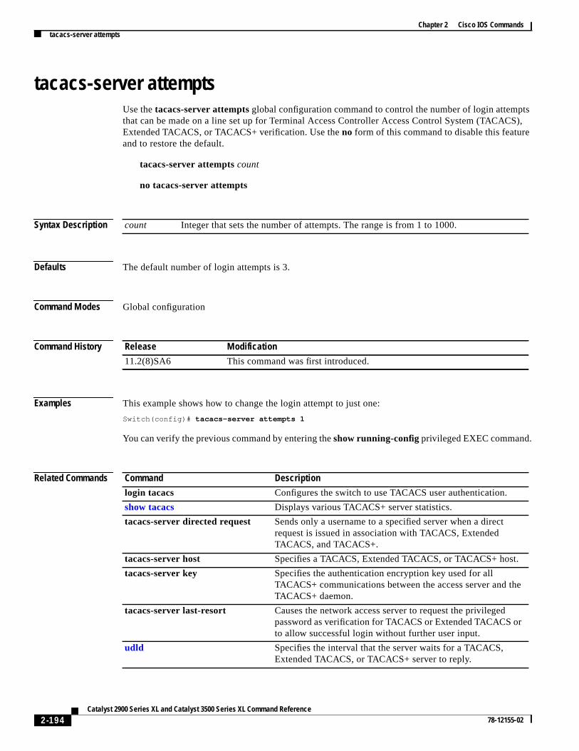
Chapter 2 Cisco IOS Commandstacacs-server attempts
tsS),
e
tacacs-server attemptsUse thetacacs-server attemptsglobal configuration command to control the number of login attempthat can be made on a line set up for Terminal Access Controller Access Control System (TACACExtended TACACS, or TACACS+ verification. Use theno form of this command to disable this featureand to restore the default.
tacacs-server attemptscount
no tacacs-server attempts
Syntax Description
Defaults The default number of login attempts is 3.
Command Modes Global configuration
Command History
Examples This example shows how to change the login attempt to just one:
Switch(config)# tacacs-server attempts 1
You can verify the previous command by entering theshow running-configprivileged EXEC command.
Related Commands
count Integer that sets the number of attempts. The range is from 1 to 1000.
Release Modification
11.2(8)SA6 This command was first introduced.
Command Description
login tacacs Configures the switch to use TACACS user authentication.
show tacacs Displays various TACACS+ server statistics.
tacacs-server directed request Sends only a username to a specified server when a directrequest is issued in association with TACACS, ExtendedTACACS, and TACACS+.
tacacs-server host Specifies a TACACS, Extended TACACS, or TACACS+ host.
tacacs-server key Specifies the authentication encryption key used for allTACACS+ communications between the access server and thTACACS+ daemon.
tacacs-server last-resort Causes the network access server to request the privilegedpassword as verification for TACACS or Extended TACACS orto allow successful login without further user input.
udld Specifies the interval that the server waits for a TACACS,Extended TACACS, or TACACS+ server to reply.
2-194Catalyst 2900 Series XL and Catalyst 3500 Series XL Command Reference
78-12155-02
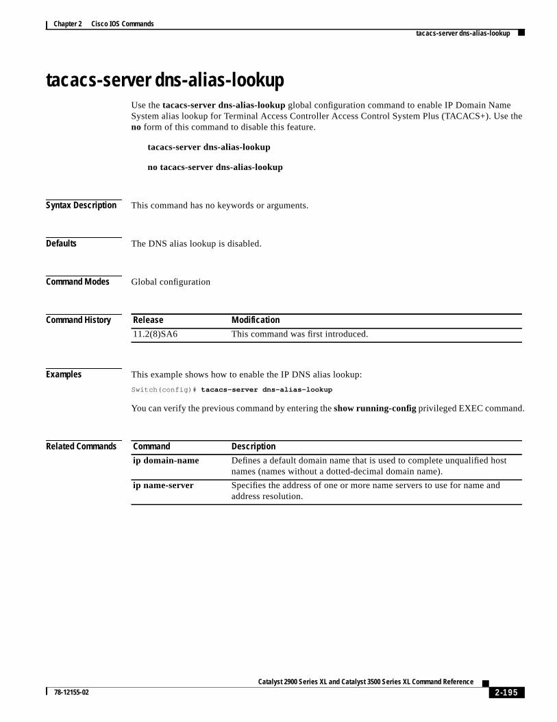
Chapter 2 Cisco IOS Commandstacacs-server dns-alias-lookup
the
tacacs-server dns-alias-lookupUse thetacacs-server dns-alias-lookup global configuration command to enable IP Domain NameSystem alias lookup for Terminal Access Controller Access Control System Plus (TACACS+). Useno form of this command to disable this feature.
tacacs-server dns-alias-lookup
no tacacs-server dns-alias-lookup
Syntax Description This command has no keywords or arguments.
Defaults The DNS alias lookup is disabled.
Command Modes Global configuration
Command History
Examples This example shows how to enable the IP DNS alias lookup:
Switch(config)# tacacs-server dns-alias-lookup
You can verify the previous command by entering theshow running-configprivileged EXEC command.
Related Commands
Release Modification
11.2(8)SA6 This command was first introduced.
Command Description
ip domain-name Defines a default domain name that is used to complete unqualified hostnames (names without a dotted-decimal domain name).
ip name-server Specifies the address of one or more name servers to use for name andaddress resolution.
2-195Catalyst 2900 Series XL and Catalyst 3500 Series XL Command Reference
78-12155-02

Chapter 2 Cisco IOS Commandsudld
a
s.
t of
udldUse theudld interface configuration command to enable UniDirectional Link Detection (UDLD) onport to assist with the detection of spanning-tree loops on logical one-way connections. Use theno formof this command to return the port setting to the global setting.
udld { enable | disable}
no udld { enable | disable}
Syntax Description
Defaults UDLD follows the setting of theudld enableglobal configuration command and is disabled on all port
Command Modes Interface configuration
Command History
Usage Guidelines UDLD is supported on fiber- and copper-based Ethernet ports.
UDLD is not supported on ATM interfaces.
A UDLD-capable port cannot detect a unidirectional link if it is connected to a UDLD-incapable poranother switch.
Setting UDLD on an interface overrides the global UDLD configuration for that specific interface.
Examples This example shows how to enable UDLD on port 2:
Switch(config)# interface fastethernet 0/2Switch(config-if)# udld enable
You can verify the previous command by entering theshow running-config or theshow udld interfacecommand in privileged EXEC mode.
Related Commands
enable Enable UDLD on the specified port.
disable Disable UDLD on the specified port.
Release Modification
12.0(5)XU This command was first introduced.
Command Description
show running-config Displays the running configuration on the switch.
udld enable Enables UDLD on all ports on the switch.
udld reset Resets any interface that has been shut down by UDLD.
2-196Catalyst 2900 Series XL and Catalyst 3500 Series XL Command Reference
78-12155-02

Chapter 2 Cisco IOS Commandsudld enable
)
t of
udld enableUse theudld enable global configuration command to enable UniDirectional Link Detection (UDLDon all ports on the switch to assist with the detection of spanning-tree loops on logical one-wayconnections. Use theno form of this command to return the switch setting to its default value.
udld enable
no udld enable
Syntax Description This command has no keywords or arguments.
Defaults UDLD is disabled on the switch.
Command Modes Global configuration mode
Command History
Usage Guidelines UDLD is supported on fiber- and copper-based Ethernet ports.
UDLD is not supported on Asynchronous Transfer Mode (ATM) interfaces.
A UDLD-capable port cannot detect a unidirectional link if it is connected to a UDLD-incapable poranother switch.
Theudld enable global configuration command setting is overwritten by each specific port UDLDconfiguration.
Examples This example shows how to enable UDLD on the switch:
Switch(config)# udld enable
You can verify the previous command by entering theshow running-config in privileged EXEC mode.
Related Commands
Release Modification
12.0(5)XU This command was first introduced.
Command Description
show running-config Displays the running configuration on the switch.
udld Enables UDLD on a port.
udld reset Resets any interface that has been shut down by UDLD.
2-197Catalyst 2900 Series XL and Catalyst 3500 Series XL Command Reference
78-12155-02
Chapter 2 Cisco IOS Commandsudld reset
udld resetUse theudld reset privileged EXEC command to reset all interfaces that have been shut down byUniDirectional Link Detection (UDLD).
udld reset
Syntax Description This command has no keywords or arguments.
Command Modes Privileged EXEC mode
Command History
Examples This example shows how to reset all interfaces that have been shut down by UDLD:
Switch# udld reset1 ports shutdown by UDLD were reset.
You can verify the previous command by entering theshow udld user EXEC command.
Related Commands
Release Modification
12.0(5)XU This command was first introduced.
Command Description
show running-config Displays the running configuration on the switch.
udld Enables UDLD on a port.
udld enable Enables UDLD on all ports on the switch.
2-198Catalyst 2900 Series XL and Catalyst 3500 Series XL Command Reference
78-12155-02

Chapter 2 Cisco IOS Commandsvlan
vlanUse thevlan VLAN database command to configure VLAN characteristics. Use theno form of thiscommand to delete a VLAN and its configured characteristics.
vlan vlan-id [namevlan-name] [media { ethernet | fddi | fdi-net | tokenring | tr-net}][state {suspend | active}] [ said said-value] [mtu mtu-size] [ ring ring-number][bridge bridge-number |type { srb | srt}] [ parent parent-vlan-id][stp type { ieee | ibm | auto}] [ are are-number] [steste-number][backupcrf {enable | disable}] [ tb-vlan1 tb-vlan1-id] [ tb-vlan2 tb-vlan2-id]
no vlan vlan-id [namevlan-name] [media { ethernet | fddi | fdi-net | tokenring | tr-net}][state {suspend | active}] [ said said-value] [mtu mtu-size] [ ring ring-number][bridge bridge-number |type { srb | srt}] [ parent parent-vlan-id][stp type { ieee | ibm | auto}] [ are are-number] [steste-number][backupcrf {enable | disable}] [ tb-vlan1 tb-vlan1-id] [ tb-vlan2 tb-vlan2-id]
Note Catalyst 2900 XL and Catalyst 3500 XL switches support only Ethernet ports. You configure onlyFDDI and Token Ring media-specific characteristics for VLAN Trunking Protocol (VTP) globaladvertisements to other switches. These VLANs are locally suspended.
Table 2-7 lists the valid syntax for each media type.
Table 2-7 Valid Syntax for Different Media Types
Media Type Valid Syntax
Ethernet vlan vlan-id [namevlan-name] media ethernet[state {suspend | active}][said said-value] [mtu mtu-size] [ tb-vlan1 tb-vlan1-id] [ tb-vlan2 tb-vlan2-id]
FDDI vlan vlan-id [namevlan-name] media fddi [state {suspend | active}][said said-value] [mtu mtu-size] [ ring ring-number] [parent parent-vlan-id][tb-vlan1 tb-vlan1-id] [ tb-vlan2 tb-vlan2-id]
FDDI-NET vlan vlan-id [namevlan-name] media fdi-net [state {suspend | active}][said said-value] [mtu mtu-size] [bridge bridge-number][stp type { ieee | ibm | auto}] [ tb-vlan1 tb-vlan1-id] [ tb-vlan2 tb-vlan2-id]
If VTP V2 mode is disabled, do not set thestp type to auto.
Token Ring VTP V2 mode is disabled.
vlan vlan-id [namevlan-name] media tokenring [state {suspend | active}][said said-value] [mtu mtu-size] [ ring ring-number] [parent parent-vlan-id][tb-vlan1 tb-vlan1-id] [ tb-vlan2 tb-vlan2-id]
Token Ringconcentratorrelay function(TRCRF)
VTP V2 mode is enabled.
vlan vlan-id [namevlan-name] media tokenring [state {suspend | active}][said said-value] [mtu mtu-size] [ ring ring-number] [parent parent-vlan-id][bridge type { srb | srt}] [ are are-number] [steste-number][backupcrf {enable | disable}] [ tb-vlan1 tb-vlan1-id] [ tb-vlan2 tb-vlan2-id]
2-199Catalyst 2900 Series XL and Catalyst 3500 Series XL Command Reference
78-12155-02
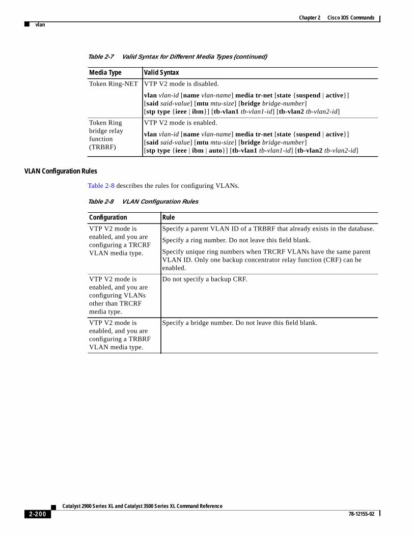
Chapter 2 Cisco IOS Commandsvlan
.
t
VLAN Configuration Rules
Table 2-8 describes the rules for configuring VLANs.
Token Ring-NET VTP V2 mode is disabled.
vlan vlan-id [namevlan-name] media tr-net [state {suspend | active}][said said-value] [mtu mtu-size] [bridge bridge-number][stp type { ieee | ibm}] [ tb-vlan1 tb-vlan1-id] [ tb-vlan2 tb-vlan2-id]
Token Ringbridge relayfunction(TRBRF)
VTP V2 mode is enabled.
vlan vlan-id [namevlan-name] media tr-net [state {suspend | active}][said said-value] [mtu mtu-size] [bridge bridge-number][stp type { ieee | ibm | auto}] [ tb-vlan1 tb-vlan1-id] [ tb-vlan2 tb-vlan2-id]
Table 2-7 Valid Syntax for Different Media Types (continued)
Media Type Valid Syntax
Table 2-8 VLAN Configuration Rules
Configuration Rule
VTP V2 mode isenabled, and you areconfiguring a TRCRFVLAN media type.
Specify a parent VLAN ID of a TRBRF that already exists in the database
Specify a ring number. Do not leave this field blank.
Specify unique ring numbers when TRCRF VLANs have the same parenVLAN ID. Only one backup concentrator relay function (CRF) can beenabled.
VTP V2 mode isenabled, and you areconfiguring VLANsother than TRCRFmedia type.
Do not specify a backup CRF.
VTP V2 mode isenabled, and you areconfiguring a TRBRFVLAN media type.
Specify a bridge number. Do not leave this field blank.
2-200Catalyst 2900 Series XL and Catalyst 3500 Series XL Command Reference
78-12155-02

Chapter 2 Cisco IOS Commandsvlan
Syntax Description
VTP V2 mode isdisabled.
No VLAN can have an STP type set to auto.
This rule applies to Ethernet, FDDI, FDDI-NET, Token Ring, and TokenRing-NET VLANs.
Add a VLAN thatrequires translationalbridging (values are notset to zero).
The translational bridging VLAN IDs that are used must already exist in thedatabase.
The translational bridging VLAN IDs that a configuration points to mustalso contain a pointer to the original VLAN in one of the translationalbridging parameters (for example, Ethernet points to FDDI, and FDDIpoints to Ethernet).
The translational bridging VLAN IDs that a configuration points to must bedifferent media types than the original VLAN (for example, Ethernet canpoint to Token Ring).
If both translational bridging VLAN IDs are configured, these VLANs mustbe different media types (for example, Ethernet can point to FDDI andToken Ring).
Table 2-8 VLAN Configuration Rules (continued)
Configuration Rule
vlan-id ID of the configured VLAN. Valid IDs are from 1 to 1005 and must beunique within the administrative domain. Do not enter leading zeroes.
name (Optional) Keyword to be followed by the VLAN name.
vlan-name ASCII string from 1 to 32 characters that must be unique within theadministrative domain.
media (Optional) Keyword to be followed by the VLAN media type.
ethernet Ethernet media type.
fddi FDDI media type.
fdi-net FDDI network entity title (NET) media type.
tokenring Token Ring media type if the VTP V2 mode is disabled.
TRCRF media type if the VTP V2 mode is enabled.
tr-net Token Ring network entity title (NET) media type if the VTP V2 mode isdisabled.
TRBRF media type if the VTP V2 mode is enabled.
state (Optional) Keyword to be followed by the VLAN state.
active VLAN is operational.
suspend VLAN is suspended. Suspended VLANs do not pass packets.
said (Optional) Keyword to be followed by the security association identifier(SAID) as documented in IEEE 802.10.
said-value Integer from 1 to 4294967294 that must be unique within the administrativedomain.
mtu (Optional) Keyword to be followed by the maximum transmission unit(packet size in bytes).
mtu-size Packet size in bytes from 1500 to 18190 that the VLAN can use.
2-201Catalyst 2900 Series XL and Catalyst 3500 Series XL Command Reference
78-12155-02

Chapter 2 Cisco IOS Commandsvlan
d
Defaults Thevlan-name variable isVLANxxxx, wherexxxx represents four numeric digits (including leadingzeroes) equal to the VLAN ID number.
Themedia type isethernet.
The state isactive.
Thesaid valueis 100000 plus the VLAN ID.
ring (Optional) Keyword to be followed by the logical ring for an FDDI, TokenRing, or TRCRF VLAN.
ring-number Integer from 1 to 4095.
bridge (Optional) Keyword to be followed by the logical distributed source-routingbridge. This bridge that interconnects all logical rings having this VLAN asa parent VLAN in FDDI-NET, Token Ring-NET, and TRBRF VLANs.
bridge-number Integer from 0 to 15.
type Keyword to be followed by the bridge type. Applies only to TRCRFVLANs.
srb Source-route bridging VLAN.
srt Source-route transparent bridging VLAN.
parent (Optional) Keyword to be followed by the parent VLAN of an existingFDDI, Token Ring, or TRCRF VLAN. This parameter identifies the TRBRFto which a TRCRF belongs and is required when defining a TRCRF.
parent-vlan-id Integer from 0 to 1005.
stp type (Optional) Keyword to be followed by the spanning-tree type forFDDI-NET, Token Ring-NET, or TRBRF VLAN.
ieee IEEE Ethernet STP running source-route transparent (SRT) bridging.
ibm IBM STP running source-route bridging (SRB).
auto STP running a combination of source-route transparent bridging (IEEE) ansource-route bridging (IBM).
are Keyword to be followed by the number of all-routes explorer (ARE) hops.This keyword applies only to TRCRF VLANs.
are-number Integer from 0 to 13 that defines the maximum number of ARE hops for thisVLAN.
ste Keyword to be followed by the number of spanning-tree explorer (STE)hops. This keyword applies only to TRCRF VLANs.
ste-number Integer from 0 to 13 that defines the maximum number of STE hops for thisVLAN.
backupcrf Keyword to be followed by the backup CRF mode. This keyword appliesonly to TRCRF VLANs.
enable Enable backup CRF mode for this VLAN.
disable Disable backup CRF mode for this VLAN.
tb-vlan1 andtb-vlan2 (Optional) Keyword to be followed by the first and second VLAN to whichthis VLAN is translationally bridged. Translational VLANs translate FDDIor Token Ring to Ethernet, for example.
tb-vlan1-id andtb-vlan2-id
Integer that ranges from 0 to 1005.
2-202Catalyst 2900 Series XL and Catalyst 3500 Series XL Command Reference
78-12155-02
Chapter 2 Cisco IOS Commandsvlan
g2
or
,ID
toN.
eID
e
).
e
Themtu sizefor Ethernet, FDDI, and FDDI-NET VLANs is 1500 bytes. The MTU size for Token Rinand Token Ring-NET VLANs is 1500 bytes. The MTU size for TRBRF and TRCRF VLANs is 447bytes.
The ring number for Token Ring VLANs is zero. For FDDI VLANs, there is no default. For TRCRFVLANs, you must specify a ring number.
The bridge number is zero (no source-routing bridge) for FDDI-NET and Token Ring-NET VLANs. FTRBRF VLANs, you must specify a bridge number.
The parent VLAN ID is zero (no parent VLAN) for FDDI and Token Ring VLANs. For TRCRF VLANsyou must specify a parent VLAN ID. For both Token Ring and TRCRF VLANs, the parent VLAN must already exist in the database and be associated with a Token Ring-NET or TRBRF VLAN.
The STP type isieeefor FDDI-NET VLANs. For Token Ring-NET and TRBRF VLANs, the default isibm.
The ARE value is 7.
The STE value is 7.
Backup CRF is disabled.
The tb-vlan1-id andtb-vlan2-id variables are zero (no translational bridging).
Command Modes VLAN database
Command History
Usage Guidelines When theno vlan vlan-id form is used, the VLAN is deleted. Deleting VLANs automatically resets zero any other parent VLANs and translational bridging parameters that refer to the deleted VLA
When theno vlan vlan-id namevlan-name form is used, the VLAN name returns to the default nam(VLANxxxx, wherexxxxrepresent four numeric digits (including leading zeroes) equal to the VLANnumber).
When theno vlan vlan-idmedia form is used, the media type returns to the default (ethernet). Changingthe VLAN media type (including theno form) resets the VLAN MTU to the default MTU for the type(unless themtu keyword is also present in the command). It also resets the VLAN parent andtranslational bridging VLAN to the default unless theparent, tb-vlan1, andtb-vlan2 keywords, or anycombination are also present in the command.
When theno vlan vlan-id state form is used, the VLAN state returns to the default (active).
When theno vlan vlan-id said form is used, the VLAN SAID returns to the default (100,000 plus thVLAN ID).
When theno vlan vlan-id mtu form is used, the VLAN MTU returns to the default for the applicableVLAN media type. You can also modify the MTU by using themedia keyword.
When theno vlan vlan-id ring form is used, the VLAN logical ring number returns to the default (0
When theno vlan vlan-id bridge form is used, the VLAN source-routing bridge number returns to thdefault (0). Thevlan vlan-idbridge command is only used for FDDI-NET and Token Ring-NET VLANsand is ignored in other VLAN types.
Release Modification
11.2(8)SA4 This command was first introduced.
2-203Catalyst 2900 Series XL and Catalyst 3500 Series XL Command Reference
78-12155-02
Chapter 2 Cisco IOS Commandsvlan
nt
e
l
lt)
g.
When theno vlan vlan-id parent form is used, the parent VLAN returns to the default (0). The pareVLAN resets to the default if the parent VLAN is deleted or if themedia keyword changes the VLANtype or the VLAN type of the parent VLAN.
When theno vlan vlan-id stp type form is used, the VLAN spanning-tree type returns to the default(ieee).
When theno vlan vlan-id tb-vlan1 or no vlan vlan-id tb-vlan2 form is used, the VLAN translationalbridge VLAN (or VLANs, if applicable) returns to the default (0). Translational bridge VLANs must ba different VLAN type than the affected VLAN, and if two are specified, the two must be differentVLAN types from each other. A translational bridge VLAN resets to the default if the translationabridge VLAN is deleted, if themedia keyword changes the VLAN type, or if themedia keywordchanges the VLAN type of the corresponding translation bridge VLAN.
Examples This example shows how to add an Ethernet VLAN with default media characteristics. The defauincludes avlan-nameof VLANxxx, wherexxxxrepresents four numeric digits (including leading zeroesequal to the VLAN ID number. The defaultmedia option isethernet; thestate option isactive. Thedefaultsaid-valuevariable is 100000 plus the VLAN ID; themtu-size variable is 1500; thestp-typeoption isieee. The VLAN is added if it did not already exist; otherwise, this command does nothin
Switch(vlan)# vlan 2
This example shows how to modify an existing VLAN by changing its name and MTU size:
Switch(vlan)# no vlan name engineering mtu 1200
You can verify the previous commands by entering theshow vlanuser EXEC command.
Related Commands Command Description
show vlan Displays the parameters for all configured VLANs or one VLAN (if the VLAN IDor name is specified) in the administrative domain.
2-204Catalyst 2900 Series XL and Catalyst 3500 Series XL Command Reference
78-12155-02

Chapter 2 Cisco IOS Commandsvlan database
and
,
d
vlan databaseUse thevlan database privileged EXEC command to enter VLAN database mode from thecommand-line interface (CLI). From the CLI, you can add, delete, and modify VLAN configurationsglobally propagate these changes by using the VLAN Trunking Protocol (VTP).
vlan database
Syntax Description This command has no arguments or keywords.
Defaults No default is defined.
Command Modes Privileged EXEC
Command History
Usage Guidelines To return to the privileged EXEC mode from the VLAN database mode, enter theexit command.
Note This command mode is different from other modes because it is session-oriented. When you adddelete, or modify VLAN parameters, the changes are not applied until you exit the session byentering theapply or exit commands. When the changes are applied, the VTP configuration versionis incremented. You can alsonot apply the changes to the VTP database by enteringabort.
Examples This example shows how to enter the VLAN database mode from the privileged EXEC mode:
Switch# vlan databaseSwitch(vlan)#
Related Commands
Release Modification
11.2(8)SA4 This command was first introduced.
Command Description
abort Abandons the proposed VLAN database, exits VLAN database mode, anreturns to privileged EXEC mode.
apply Implements the proposed VLAN database, increments the databaseconfiguration revision number, propagates it throughout the administrativedomain, and remains in VLAN database mode.
reset Abandons the proposed VLAN database and remains in VLAN databasemode. Resets the proposed database to the currently implemented VLANdatabase on the switch.
shutdown vlan Shuts down (suspends) local traffic on the specified VLAN.
2-205Catalyst 2900 Series XL and Catalyst 3500 Series XL Command Reference
78-12155-02

Chapter 2 Cisco IOS Commandsvmps reconfirm (privileged EXEC)
)
g or
vmps reconfirm (privileged EXEC)Use thevmps reconfirm privileged EXEC command to immediately send VLAN Query Protocol (VQPqueries to reconfirm all dynamic VLAN assignments with the VLAN Membership Policy Server(VMPS).
vmps reconfirm
Syntax Description This command has no arguments or keywords.
Defaults No default is defined.
Command Modes Privileged EXEC
Command History
Examples This example shows how to immediately send VQP queries to the VMPS:
Switch# vmps reconfirm
You can verify the previous command by entering theshow vmpsuser EXEC command and examiningthe VMPS Action row of the Reconfirmation Status section. Theshow vmpscommand shows the resultof the last time the assignments were reconfirmed either as a result of reconfirmation timer expirinbecause thevmps reconfirm command was entered.
Related Commands
Release Modification
11.2(8)SA4 This command was first introduced.
Command Description
show vmps Displays VQP and VMPS information.
vmps reconfirm(privileged EXEC)
and
vmps reconfirm(global Configuration)
Sends VQP queries to reconfirm all dynamic VLAN assignments with theVMPS.
2-206Catalyst 2900 Series XL and Catalyst 3500 Series XL Command Reference
78-12155-02

Chapter 2 Cisco IOS Commandsvmps reconfirm (global Configuration)
e
tes:
vmps reconfirm (global Configuration)Use thevmps reconfirm global configuration command to change the reconfirmation interval for thVLAN Query Protocol (VQP) client.
vmps reconfirm interval
Syntax Description
Defaults The default reconfirmation interval is 60 minutes.
Command Modes Global configuration
Command History
Examples This example shows how to set the VQP client to reconfirm dynamic VLAN entries every 20 minu
Switch(config)# vmps reconfirm 20
You can verify the previous command by entering theshow vmpsuser EXEC command and examininginformation in the Reconfirm Interval row.
Related Commands
interval Reconfirmation interval for VQP client queries to the VLAN Membership PolicyServer (VMPS) to reconfirm dynamic VLAN assignments. The interval range isfrom 1 to 120 minutes.
Release Modification
11.2(8)SA4 This command was first introduced.
Command Description
show vmps Displays VQP and VMPS information.
vmps reconfirm(privileged EXEC) and
vmps reconfirm(global Configuration)
Sends VQP queries to reconfirm all dynamic VLAN assignments with theVMPS.
2-207Catalyst 2900 Series XL and Catalyst 3500 Series XL Command Reference
78-12155-02

Chapter 2 Cisco IOS Commandsvmps retry
N
vmps retryUse thevmps retry global configuration command to configure the per-server retry count for the VLAQuery Protocol (VQP) client.
vmps retry count
Syntax Description
Defaults The default retry count is 3.
Command Modes Global configuration
Command History
Examples This example shows how to set the retry count to 7:
Switch(config)# vmps retry 7
You can verify the previous command by entering theshow vmpsuser EXEC command and examininginformation in the Server Retry Count row.
Related Commands
count Number of attempts to contact the VLAN Membership Policy Server (VMPS) by theclient before querying the next server in the list. The retry range is from 1 to 10.
Release Modification
11.2(8)SA4 This command was first introduced.
Command Description
show vmps Displays VQP and VMPS information.
2-208Catalyst 2900 Series XL and Catalyst 3500 Series XL Command Reference
78-12155-02
Chapter 2 Cisco IOS Commandsvmps server
y
se thehe thes.
m new
fy
vmps serverUse thevmps serverglobal configuration command to configure the primary VLAN Membership PolicServer (VMPS) and up to three secondary servers. Use theno form of this command to remove a VMPSserver.
vmps serveripaddress [primary ]
no vmps server [ipaddress]
Syntax Description
Defaults No primary or secondary VMPS servers are defined.
Command Modes Global configuration
Command History
Usage Guidelines The first server entered is automatically selected as the primary server whether or notprimary isentered. The first server address can be overridden by usingprimary in a subsequent command.
If a member switch in a cluster configuration does not have an IP address, the cluster does not uVMPS server configured for that member switch. Instead, the cluster uses the VMPS server on tcommand switch, and the command switch proxies the VMPS requests. The VMPS server treatscluster as a single switch and uses the IP address of the command switch to respond to request
When using theno form without specifying theipaddress, all configured servers are deleted. If youdelete all servers when dynamic-access ports are present, the switch cannot forward packets frosources on these ports because it cannot query the VMPS.
ipaddress IP address or host name of the primary or secondary VMPS servers. If you specia host name, the Domain Name System (DNS) server must be configured.
primary (Optional) Determines whether primary or secondary VMPS servers are beingconfigured.
Release Modification
11.2(8)SA4 This command was first introduced.
2-209Catalyst 2900 Series XL and Catalyst 3500 Series XL Command Reference
78-12155-02
Chapter 2 Cisco IOS Commandsvmps server
PSary
Examples This example shows how to configure the server with IP address 191.10.49.20 as the primary VMserver. The servers with IP addresses 191.10.49.21 and 191.10.49.22 are configured as secondservers:
Switch(config)# vmps server 191.10.49.20 primarySwitch(config)# vmps server 191.10.49.21Switch(config)# vmps server 191.10.49.22
This example shows how to delete the server with IP address 191.10.49.21:
Switch(config)# no vmps server 191.10.49.21
You can verify the previous commands by entering theshow vmpsuser EXEC command and examininginformation in the VMPS Domain Server row.
Related Commands Command Description
show vmps Displays VQP and VMPS information.
2-210Catalyst 2900 Series XL and Catalyst 3500 Series XL Command Reference
78-12155-02

Chapter 2 Cisco IOS Commandsvtp
he
d
to
istssn
vtpUse thevtp VLAN database command to configure the VLAN Trunking Protocol (VTP) mode. Use tno form of this command to return to the default setting.
vtp { server | client | transparent}
no vtp { server | client | transparent}
Syntax Description
Note The switch supports up to 250 VLANs on the Catalyst 2912MF, 2924M, and Catalyst 3500 XLswitches. All other Catalyst 2900 XL switches support up to 64 VLANs. If you define more than 250or 64, respectively, or if the switch receives an advertisement that contains more than 250 or 64VLANs, the switch automatically enters VTP transparent mode and operates with the VLANconfiguration preceding the one that put it into transparent mode. The count of 250 or 64 VLANsalways includes VLAN 1 but never includes VLANs 1002 to 1005. The switch can have 250 or 64active VLANs, plus VLANs 1002 through 1005, which are inactive.
Defaults Server mode is the default mode.
Command Modes VLAN database
Command History
server Place the switch in VTP server mode. A switch in VTP server mode is enablefor VTP and sends advertisements. You can configure VLANs on it. The switchcan recover all the VLAN information in the VTP database from nonvolatilestorage after reboot.
client Place the switch in VTP client mode. A switch in VTP client mode is enabled forVTP, can send advertisements, but does not have enough nonvolatile storagestore VLAN configurations. You cannot configure VLANs on it. When a VTPclient starts up, it does not transmit VTP advertisements until it receivesadvertisements to initialize its VLAN database.
transparent Place the switch in VTP transparent mode. A switch in VTP transparent modedisabled for VTP, does not transmit advertisements or learn from advertisemensent by other devices, and cannot affect VLAN configurations on other devicein the network. The switch receives VTP advertisements and forwards them oall trunk ports except the one on which the advertisement was received. Theconfiguration of multi-VLAN ports causes the switch to automatically entertransparent mode.
Release Modification
11.2(8)SA4 This command was first introduced.
2-211Catalyst 2900 Series XL and Catalyst 3500 Series XL Command Reference
78-12155-02

Chapter 2 Cisco IOS Commandsvtp
e.
,
Usage Guidelines Theno vtp client andno vtp transparent forms of the command return the switch to VTP server mod
Thevtp server command is the same asno vtp client or no vtp transparent except that it does notreturn an error if the switch is not in client or transparent mode.
Examples This example shows how to place the switch in VTP transparent mode:
Switch(vlan)# vtp transparent
You can verify the previous commands by entering theshow vtp status privileged EXEC command.
Related Commands Command Description
show vtp status Displays general information about the VTP management domain, statusand counters.
2-212Catalyst 2900 Series XL and Catalyst 3500 Series XL Command Reference
78-12155-02

Chapter 2 Cisco IOS Commandsvtp domain
henges
amesetste, it
e
main.
,
vtp domainUse thevtp domain VLAN database command to configure the VLAN Trunking Protocol (VTP)administrative domain.
vtp domain domain-name
Syntax Description
Defaults No domain name is defined.
Command Modes VLAN database
Command History
Usage Guidelines The switch is in the no-management-domain state until you configure a domain name. While in tno-management-domain state, the switch does not transmit any VTP advertisements even if chaoccur to the local VLAN configuration. The switch leaves the no-management-domain state afterreceiving the first VTP summary packet on any port that is trunking or after you configure a domain nby using thevtp domain command. If the switch receives its domain from a summary packet, it reits configuration revision number to zero. After the switch leaves the no-management-domain stacan never be configured to reenter it until you clear the nonvolatile RAM (NVRAM) and reload thsoftware.
Domain names are case sensitive.
Once you configure a domain name, it cannot be removed. You can only reassign it to a different do
Examples This example shows how to set the administrative domain for the switch:
Switch(vlan)# vtp domain OurDomainName
You can verify the previous commands by entering theshow vtp status user EXEC command.
Related Commands
domain-name ASCII string from 1 to 32 characters that identifies the VTP administrative domainfor the switch. The domain name is case sensitive.
Release Modification
11.2(8)SA4 This command was first introduced.
Command Description
show vtp status Displays general information about the VTP management domain, statusand counters.
vtp password Configures the VTP administrative domain password.
2-213Catalyst 2900 Series XL and Catalyst 3500 Series XL Command Reference
78-12155-02

Chapter 2 Cisco IOS Commandsvtp file
ting
vtp fileUse thevtp file global configuration command to modify the VLAN Trunking Protocol (VTP)configuration storage filename. Use theno form of this command to return the filename to its defaultname.
vtp file ifsfilename
no vtp file
Syntax Description
Defaults The default filename isflash:vlan.dat.
Command Modes Global configuration
Command History
Usage Guidelines This command cannot be used to load a new database; it only renames the file in which the exisdatabase is stored.
Examples This example shows how to rename the filename for VTP configuration storage tovtpfilename:
Switch(config)# vtp file vtpfilename
Related Commands
ifsfilename The IOS IFS filename where the VTP VLAN configuration is stored.
Release Modification
11.2(8)SA4 This command was first introduced.
Command Description
vtp Configures the VTP mode.
2-214Catalyst 2900 Series XL and Catalyst 3500 Series XL Command Reference
78-12155-02

Chapter 2 Cisco IOS Commandsvtp password
ate.
5d
vtp passwordUse thevtp passwordVLAN database command to configure the VLAN Trunking Protocol (VTP)administrative domain password. Use theno form of this command to remove the password.
vtp passwordpassword-value
no vtp passwordpassword-value
Syntax Description
Defaults No password is defined.
Command Modes VLAN database
Command History
Usage Guidelines Passwords are case sensitive. Passwords should match on all switches in the same domain.
When theno vtp password form of the command is used, the switch returns to the no-password st
Examples This example shows how to configure the VTP domain password:
Switch(vlan)# vtp password ThisIsOurDomainsPassword
Related Commands
password Set the password for the generation of the 16-byte secret value used in MDdigest calculation to be sent in VTP advertisements and to validate receiveVTP advertisements.
password-value ASCII string from 8 to 64 characters. The password is case sensitive.
Release Modification
11.2(8)SA4 This command was first introduced.
Command Description
vtp domain Configures the VTP administrative domain.
2-215Catalyst 2900 Series XL and Catalyst 3500 Series XL Command Reference
78-12155-02

Chapter 2 Cisco IOS Commandsvtp pruning
s.
vtp pruningUse thevtp pruning VLAN database command toenable pruning in the VLAN Trunking Protocol (VTP)administrative domain.Use theno form of this command to disable pruning.
vtp pruning
no vtp pruning
Syntax Description This command has no arguments or keywords.
Defaults Pruning is disabled.
Command Modes VLAN database
Command History
Usage Guidelines If you enable pruning on the VTP server, it is enabled for the entire management domain.
Only VLANs included in the pruning-eligible list can be pruned.
VLANs 2 through 1001 are pruning-eligible on Catalyst 2900 XL and Catalyst 3500 XL trunk port
Pruning is supported with VTP version 1 and version 2.
Examples This example shows how to enable pruning in the proposed VLAN database:
Switch(vlan)# vtp pruning
You can verify the previous commands by entering theshow vtp status user EXEC command.
Related Commands
Release Modification
11.2(8)SA4 This command was first introduced.
Command Description
show interfaceinterface-id pruning Displays pruning information for the trunk port.
show vtp status Displays general information about the VTP managementdomain, status, and counters.
switchport trunk pruning Configures the VLAN pruning-eligible list for ports intrunking mode.
2-216Catalyst 2900 Series XL and Catalyst 3500 Series XL Command Reference
78-12155-02
Chapter 2 Cisco IOS Commandsvtp v2-mode
in
ode,rate
lay
1.
,
vtp v2-modeUse thevtp v2-modeVLAN database command to enable VLAN Trunking Protocol (VTP) version 2the administrative domains. Use theno form of this command to disable V2 mode.
vtp v2-mode
no vtp v2-mode
Syntax Description This command has no arguments or keywords.
Defaults VTP version 2 is disabled.
Command Modes VLAN database
Command History
Usage Guidelines Toggling the V2 mode state modifies certain parameters of certain default VLANs.
Each VTP switch automatically detects the capabilities of all the other VTP devices. To use V2 mall VTP switches in the network must support version 2; otherwise, you must configure them to opein VTP version 1 mode (no vtp v2-mode).
If you are using VTP in a Token Ring environment, VTP V2 mode must be enabled.
If you are configuring a Token Ring bridge relay function (TRBRF) or Token Ring concentrator refunction (TRCRF) VLAN media type, you must use version 2.
If you are configuring a Token Ring or Token Ring-NET VLAN media type, you must use version
Examples This example shows how to enable V2 mode in the proposed VLAN database:
Switch(vlan)# vtp v2-mode
You can verify the previous commands by entering theshow vtp status user EXEC command.
Related Commands
Release Modification
11.2(8)SA4 This command was first introduced.
Command Description
show vtp status Displays general information about the VTP management domain, statusand counters.
vtp Configures the VTP mode.
vtp pruning Enables pruning in the VTP administrative domain.
2-217Catalyst 2900 Series XL and Catalyst 3500 Series XL Command Reference
78-12155-02

Chapter 2 Cisco IOS Commandsvtp v2-mode
2-218Catalyst 2900 Series XL and Catalyst 3500 Series XL Command Reference
78-12155-02