cisco mds9000 configuration guide, cisco
TRANSCRIPT
C H A P T E R
Send documenta t ion comments to dcnm-san -doc feedback@c i sco .com
1-1Fabric Configuration Guide, Cisco DCNM for SAN
OL-27533-01, DCNM for SAN, Release 6.x
1Configuring FICON
Fibre Connection (FICON) interface capabilities enhance the Cisco MDS 9000 Family by supporting both open systems and mainframe storage network environments. The control unit port (CUP) also is supported, which allows in-band management of the switch from FICON processors.
Note Cisco Fabric Manager release 3.x does not support FICON management of Cisco MDS 9000 Family switches running SAN-OS release 2.(x).
This chapter includes the following topics:
• Information About FICON, page 1-1
• Licensing Requirements for FICON, page 1-18
• Guidelines and Limitations, page 1-19
• Default Settings, page 1-20
• Configuring FICON, page 1-20
• Configuring FICON Ports, page 1-27
• Verifying FICON Configuration, page 1-34
• Field Descriptions for FICON, page 1-37
• Additional References, page 1-40
• Feature History for FICON, page 1-41
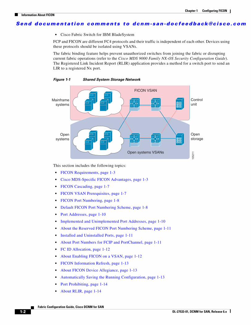
Information About FICONThe Cisco MDS 9000 Family supports the Fibre Channel Protocol (FCP), FICON, iSCSI, and FCIP capabilities within a single, high-availability platform (see Figure 1-1).
The FICON feature is not supported on:
• Cisco MDS 9120 switches
• Cisco MDS 9124 switches
• Cisco MDS 9140 switches
• The 32-port Fibre Channel switching module
• Cisco Fabric Switch for HP c-Class BladeSystem
Send documenta t ion comments to dcnm-san -doc feedback@c i sco .com
1-2Fabric Configuration Guide, Cisco DCNM for SAN
OL-27533-01, DCNM for SAN, Release 6.x
Chapter 1 Configuring FICONInformation About FICON
• Cisco Fabric Switch for IBM BladeSystem
FCP and FICON are different FC4 protocols and their traffic is independent of each other. Devices using these protocols should be isolated using VSANs.
The fabric binding feature helps prevent unauthorized switches from joining the fabric or disrupting current fabric operations (refer to the Cisco MDS 9000 Family NX-OS Security Configuration Guide). The Registered Link Incident Report (RLIR) application provides a method for a switch port to send an LIR to a registered Nx port.
Figure 1-1 Shared System Storage Network
This section includes the following topics:
• FICON Requirements, page 1-3
• Cisco MDS-Specific FICON Advantages, page 1-3
• FICON Cascading, page 1-7
• FICON VSAN Prerequisites, page 1-7
• FICON Port Numbering, page 1-8
• Default FICON Port Numbering Scheme, page 1-8
• Port Addresses, page 1-10
• Implemented and Unimplemented Port Addresses, page 1-10
• About the Reserved FICON Port Numbering Scheme, page 1-11
• Installed and Uninstalled Ports, page 1-11
• About Port Numbers for FCIP and PortChannel, page 1-11
• FC ID Allocation, page 1-12
• About Enabling FICON on a VSAN, page 1-12
• FICON Information Refresh, page 1-13
• About FICON Device Allegiance, page 1-13
• Automatically Saving the Running Configuration, page 1-13
• Port Prohibiting, page 1-14
• About RLIR, page 1-14
Openstorage
Opensystems
Controlunit
Mainframesystems
Open systems VSANs
FICON VSAN
1052
11
Send documenta t ion comments to dcnm-san -doc feedback@c i sco .com
1-3Fabric Configuration Guide, Cisco DCNM for SAN
OL-27533-01, DCNM for SAN, Release 6.x
Chapter 1 Configuring FICONInformation About FICON
• Port Swapping, page 1-16
• FICON Tape Acceleration, page 1-16
• CUP In-Band Management, page 1-18
FICON RequirementsThe FICON feature has the following requirements:
• You can implement FICON features in the following switches:
– Any switch in the Cisco MDS 9500 Series
– Any switch in the Cisco MDS 9200 Series (including the Cisco MDS 9222i Multiservice Modular Switch)
– Cisco MDS 9134 Multilayer Fabric Switch
– MDS 9000 Family 18/4-Port Multiservice Module
• You need the MAINFRAME_PKG license to configure FICON parameters.
• To extend your FICON configuration over a WAN link using FCIP, you need the appropriate SAN_EXTN_OVER_IP license for the module you are using. For more information, refer to the Cisco NX-OS Family Licensing Guide.
Cisco MDS-Specific FICON AdvantagesThis section explains the additional FICON advantages in Cisco MDS switches and includes the following topics:
• Fabric Optimization with VSANs, page 1-3
• FCIP Support, page 1-5
• PortChannel Support, page 1-5
• VSANs for FICON and FCP Mixing, page 1-5
• Cisco MDS-Supported FICON Features, page 1-5
Fabric Optimization with VSANs
Generally, separate physical fabrics have a high level of switch management and have a higher implementation cost. The ports in each island also may be over-provisioned depending on the fabric configuration.
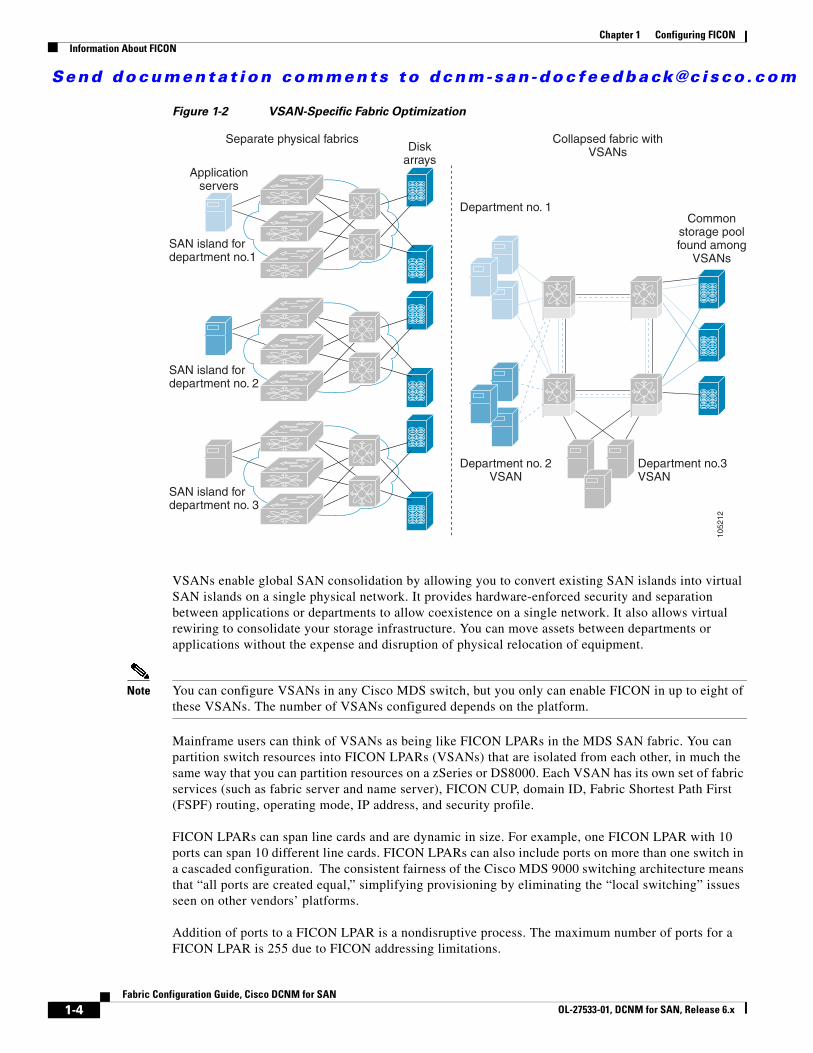
By using the Cisco MDS-specific VSAN technology, you can have greater efficiency between these physical fabrics by lowering the cost of over-provisioning and reducing the number of switches to be managed. VSANs also help you to move unused ports nondisruptively and provide a common redundant physical infrastructure (see Figure 1-2).
Send documenta t ion comments to dcnm-san -doc feedback@c i sco .com
1-4Fabric Configuration Guide, Cisco DCNM for SAN
OL-27533-01, DCNM for SAN, Release 6.x
Chapter 1 Configuring FICONInformation About FICON
Figure 1-2 VSAN-Specific Fabric Optimization
VSANs enable global SAN consolidation by allowing you to convert existing SAN islands into virtual SAN islands on a single physical network. It provides hardware-enforced security and separation between applications or departments to allow coexistence on a single network. It also allows virtual rewiring to consolidate your storage infrastructure. You can move assets between departments or applications without the expense and disruption of physical relocation of equipment.
Note You can configure VSANs in any Cisco MDS switch, but you only can enable FICON in up to eight of these VSANs. The number of VSANs configured depends on the platform.
Mainframe users can think of VSANs as being like FICON LPARs in the MDS SAN fabric. You can partition switch resources into FICON LPARs (VSANs) that are isolated from each other, in much the same way that you can partition resources on a zSeries or DS8000. Each VSAN has its own set of fabric services (such as fabric server and name server), FICON CUP, domain ID, Fabric Shortest Path First (FSPF) routing, operating mode, IP address, and security profile.
FICON LPARs can span line cards and are dynamic in size. For example, one FICON LPAR with 10 ports can span 10 different line cards. FICON LPARs can also include ports on more than one switch in a cascaded configuration. The consistent fairness of the Cisco MDS 9000 switching architecture means that “all ports are created equal,” simplifying provisioning by eliminating the “local switching” issues seen on other vendors’ platforms.
Addition of ports to a FICON LPAR is a nondisruptive process. The maximum number of ports for a FICON LPAR is 255 due to FICON addressing limitations.
Separate physical fabrics Collapsed fabric withVSANs
SAN island fordepartment no.1
SAN island fordepartment no. 2
SAN island fordepartment no. 3
Applicationservers
Diskarrays
Department no. 1
Department no. 2VSAN
Department no.3VSAN
Commonstorage poolfound among
VSANs
1052
12
Send documenta t ion comments to dcnm-san -doc feedback@c i sco .com
1-5Fabric Configuration Guide, Cisco DCNM for SAN
OL-27533-01, DCNM for SAN, Release 6.x
Chapter 1 Configuring FICONInformation About FICON
FCIP Support
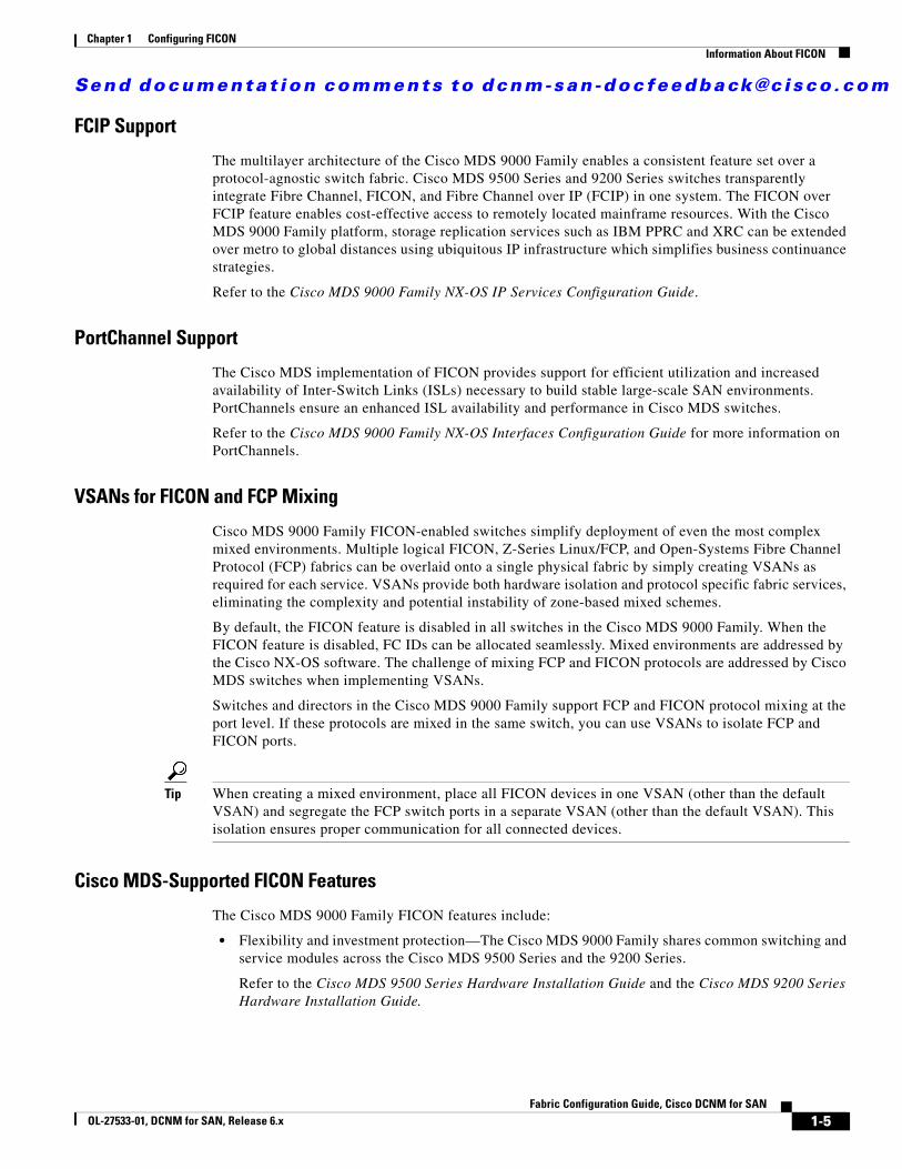
The multilayer architecture of the Cisco MDS 9000 Family enables a consistent feature set over a protocol-agnostic switch fabric. Cisco MDS 9500 Series and 9200 Series switches transparently integrate Fibre Channel, FICON, and Fibre Channel over IP (FCIP) in one system. The FICON over FCIP feature enables cost-effective access to remotely located mainframe resources. With the Cisco MDS 9000 Family platform, storage replication services such as IBM PPRC and XRC can be extended over metro to global distances using ubiquitous IP infrastructure which simplifies business continuance strategies.
Refer to the Cisco MDS 9000 Family NX-OS IP Services Configuration Guide.
PortChannel Support
The Cisco MDS implementation of FICON provides support for efficient utilization and increased availability of Inter-Switch Links (ISLs) necessary to build stable large-scale SAN environments. PortChannels ensure an enhanced ISL availability and performance in Cisco MDS switches.
Refer to the Cisco MDS 9000 Family NX-OS Interfaces Configuration Guide for more information on PortChannels.
VSANs for FICON and FCP Mixing
Cisco MDS 9000 Family FICON-enabled switches simplify deployment of even the most complex mixed environments. Multiple logical FICON, Z-Series Linux/FCP, and Open-Systems Fibre Channel Protocol (FCP) fabrics can be overlaid onto a single physical fabric by simply creating VSANs as required for each service. VSANs provide both hardware isolation and protocol specific fabric services, eliminating the complexity and potential instability of zone-based mixed schemes.
By default, the FICON feature is disabled in all switches in the Cisco MDS 9000 Family. When the FICON feature is disabled, FC IDs can be allocated seamlessly. Mixed environments are addressed by the Cisco NX-OS software. The challenge of mixing FCP and FICON protocols are addressed by Cisco MDS switches when implementing VSANs.
Switches and directors in the Cisco MDS 9000 Family support FCP and FICON protocol mixing at the port level. If these protocols are mixed in the same switch, you can use VSANs to isolate FCP and FICON ports.
Tip When creating a mixed environment, place all FICON devices in one VSAN (other than the default VSAN) and segregate the FCP switch ports in a separate VSAN (other than the default VSAN). This isolation ensures proper communication for all connected devices.
Cisco MDS-Supported FICON Features
The Cisco MDS 9000 Family FICON features include:
• Flexibility and investment protection—The Cisco MDS 9000 Family shares common switching and service modules across the Cisco MDS 9500 Series and the 9200 Series.
Refer to the Cisco MDS 9500 Series Hardware Installation Guide and the Cisco MDS 9200 Series Hardware Installation Guide.
Send documenta t ion comments to dcnm-san -doc feedback@c i sco .com
1-6Fabric Configuration Guide, Cisco DCNM for SAN
OL-27533-01, DCNM for SAN, Release 6.x
Chapter 1 Configuring FICONInformation About FICON
• High-availability FICON-enabled director—The Cisco MDS 9500 Series combines nondisruptive software upgrades, stateful process restart and failover, and full redundancy of all major components for a new standard in director-class availability. It supports up to 528 autosensing, 4/2/1-Gbps, 10-Gbps, FICON or FCP ports in any combination in a single chassis. Refer to the Cisco MDS 9000 Family NX-OS High Availability and Redundancy Configuration Guide.
• Infrastructure protection—Common software releases provide infrastructure protection across all Cisco MDS 9000 platforms. Refer to the Cisco MDS 9000 Family NX-OS Software Upgrade and Downgrade Guide.
• VSAN technology—The Cisco MDS 9000 Family provides VSAN technology for hardware-enforced, isolated environments within a single physical fabric for secure sharing of physical infrastructure and enhanced FICON mixed support. See Chapter 1, “Configuring and Managing VSANs.”
• Port-level configurations—There are BB_credits, beacon mode, and port security for each port. Refer to the Cisco MDS 9000 Family NX-OS Interfaces Configuration Guide for information about buffer-to-buffer credits, beacon LEDs, and trunking.
• Alias name configuration—Provides user-friendly aliases instead of the WWN for switches and attached node devices. See Chapter 1, “Configuring and Managing Zones.”
• Comprehensive security framework—The Cisco MDS 9000 Family supports RADIUS and TACACS+ authentication, Simple Network Management Protocol Version 3 (SNMPv3), role-based access control, Secure Shell Protocol (SSH), Secure File Transfer Protocol (SFTP), VSANs, hardware-enforced zoning, ACLs, fabric binding, Fibre Channel Security Protocol (FC-SP), LUN zoning, read-only zones, and VSAN-based access control. Refer to the Cisco MDS 9000 Family NX-OS Security Configuration Guide for information about RADIUS, TACACS+, FC-SP, and DHCHAP.
• Traffic encryption—IPsec is supported over FCIP. You can encrypt FICON and Fibre Channel traffic that is carried over FCIP. Refer to the Cisco MDS 9000 Family NX-OS Security Configuration Guide.
• Local accounting log—View the local accounting log to locate FICON events. For more information about MSCHAP authentication, and local AAA services, refer to the Cisco MDS 9000 Family NX-OS Security Configuration Guide.
• Unified storage management—Cisco MDS 9000 FICON-enabled switches are fully IBM CUP standard compliant for in-band management using the IBM S/A OS/390 I/O operations console. See the “CUP In-Band Management” section on page 1-18.
• Port address-based configurations—Configure port name, blocked or unblocked state, and the prohibit connectivity attributes can be configured on the ports. See the “Configuring FICON Ports” section on page 1-27.
• You can display the following information:
– Individual Fibre Channel ports, such as the port name, port number, Fibre Channel address, operational state, type of port, and login data.
– Nodes attached to ports.
– Port performance and statistics.
See the “Calculating FICON Flow Load Balance” section on page 1-33.
• Configuration files—Store and apply configuration files. See the “FICON Configuration Files” section on page 1-15.
• FICON and Open Systems Management Server features if installed. —See the “VSANs for FICON and FCP Mixing” section on page 1-5.
• Enhanced cascading support—See the “CUP In-Band Management” section on page 1-18.
Send documenta t ion comments to dcnm-san -doc feedback@c i sco .com
1-7Fabric Configuration Guide, Cisco DCNM for SAN
OL-27533-01, DCNM for SAN, Release 6.x
Chapter 1 Configuring FICONInformation About FICON
• Date and time—Set the date and time on the switch. See the “Allowing the Host to Control the Timestamp” section on page 1-25.
• Configure SNMP trap recipients and community names—See the “Configuring SNMP Control of FICON Parameters” section on page 1-26.
• Call Home configurations—Configure the director name, location, description, and contact person. Refer to the Cisco MDS 9000 Family NX-OS System Management Configuration Guide.
• Configure preferred domain ID, FC ID persistence, and principal switch priority—For information about configuring domain parameters, refer to the Cisco MDS 9000 Family NX-OS System Management Configuration Guide.
• Sophisticated SPAN diagnostics—The Cisco MDS 9000 Family provides industry-first intelligent diagnostics, protocol decoding, and network analysis tools as well as integrated Call Home capability for added reliability, faster problem resolution, and reduced service costs. For information about monitoring network traffic using SPAN, refer to the Cisco MDS 9000 Family NX-OS System Management Configuration Guide.
• Configure R_A_TOV, E_D_TOV—— See the “Fibre Channel Time-Out Values” section on page 1-2.
• Director-level maintenance tasks—Perform maintenance tasks for the director including maintaining firmware levels, accessing the director logs, and collecting data to support failure analysis. For information about monitoring system processes and logs refer to the Cisco MDS 9000 Family NX-OS System Management Configuration Guide.
FICON CascadingThe Cisco MDS NX-OS software allows multiple switches in a FICON network. To configure multiple switches, you must enable and configure fabric binding in that switch (see the “Calculating FICON Flow Load Balance” section on page 1-33 and refer to the Cisco MDS 9000 Family NX-OS Security Configuration Guide).
FICON VSAN PrerequisitesTo ensure that a FICON VSAN is operationally up, be sure to verify the following requirements:
• Set the default zone to permit, if you are not using the zoning feature. See the “About the Default Zone” section on page 1-6.
• Enable in-order delivery on the VSAN. See Chapter 1, “Configuring Fibre Channel Routing Services and Protocols.”
• Enable (and if required, configure) fabric binding on the VSAN. See the “Calculating FICON Flow Load Balance” section on page 1-33. For more information about Fabric Binding, refer to the Cisco MDS 9000 Family NX-OS Security Configuration Guide.
• Verify that conflicting persistent FC IDs do not exist in the switch. For information about configuring domain parameters, refer to the Cisco MDS 9000 Family NX-OS System Management Configuration Guide.
• Verify that the configured domain ID and requested domain ID match. For information about configuring domain parameters, refer to the Cisco MDS 9000 Family NX-OS System Management Configuration Guide.
Send documenta t ion comments to dcnm-san -doc feedback@c i sco .com
1-8Fabric Configuration Guide, Cisco DCNM for SAN
OL-27533-01, DCNM for SAN, Release 6.x
Chapter 1 Configuring FICONInformation About FICON
• Add the CUP (area FE) to the zone, if you are using zoning. See the “CUP In-Band Management” section on page 1-18.
If any of these requirements are not met, the FICON feature cannot be enabled.
FICON Port NumberingWith reference to the FICON feature, ports in Cisco MDS switches are identified by a statically defined 8-bit value known as the port number. A maximum of 255 port numbers are available. You can use the following port numbering schemes:
• Default port numbers based on the chassis type
• Reserved port numbers
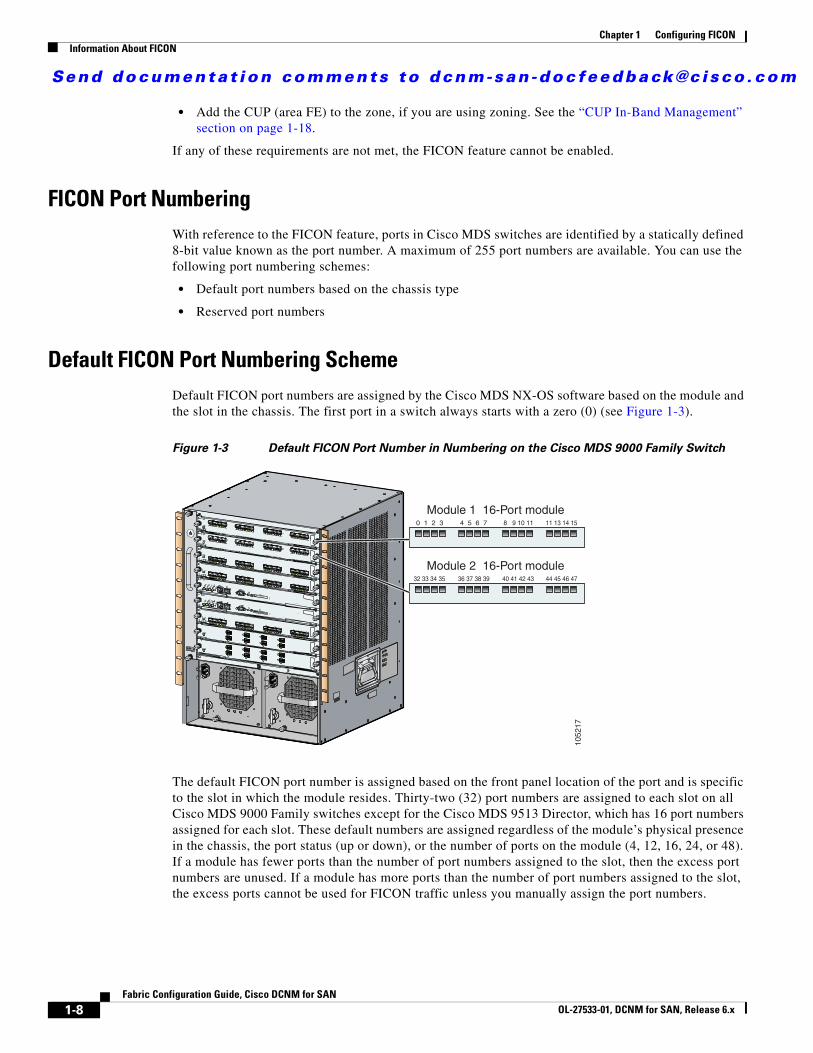
Default FICON Port Numbering SchemeDefault FICON port numbers are assigned by the Cisco MDS NX-OS software based on the module and the slot in the chassis. The first port in a switch always starts with a zero (0) (see Figure 1-3).
Figure 1-3 Default FICON Port Number in Numbering on the Cisco MDS 9000 Family Switch
The default FICON port number is assigned based on the front panel location of the port and is specific to the slot in which the module resides. Thirty-two (32) port numbers are assigned to each slot on all Cisco MDS 9000 Family switches except for the Cisco MDS 9513 Director, which has 16 port numbers assigned for each slot. These default numbers are assigned regardless of the module’s physical presence in the chassis, the port status (up or down), or the number of ports on the module (4, 12, 16, 24, or 48). If a module has fewer ports than the number of port numbers assigned to the slot, then the excess port numbers are unused. If a module has more ports than the number of port numbers assigned to the slot, the excess ports cannot be used for FICON traffic unless you manually assign the port numbers.
0 1 2 3 4 5 6 7 8 9 10 11 11 13 14 15
Module 1 16-Port module
32 33 34 35 36 37 38 39 40 41 42 43 44 45 46 47
Module 2 16-Port module10
5217
Send documenta t ion comments to dcnm-san -doc feedback@c i sco .com
1-9Fabric Configuration Guide, Cisco DCNM for SAN
OL-27533-01, DCNM for SAN, Release 6.x
Chapter 1 Configuring FICONInformation About FICON
Note Follow the steps in “Assigning FICON Port Numbers to Slots” section on page 1-21 to make use of excess ports by manually assigning more port numbers to the slots. Before doing this, however, we recommend that you review the default port number assignments for Cisco MDS 9000 switches shown in Table 1-3 on page 1-20 Table 1-1, and that you read the following sections to gain a complete understanding of FICON port numbering: “About the Reserved FICON Port Numbering Scheme” section on page 1-11, “FICON Port Numbering Guidelines” section on page 1-19, and “Assigning FICON Port Numbers to Slots” section on page 1-21.
Note Only Fibre Channel, PortChannel, and FCIP ports are mapped to FICON port numbers. Other types of interfaces do not have a corresponding port number.
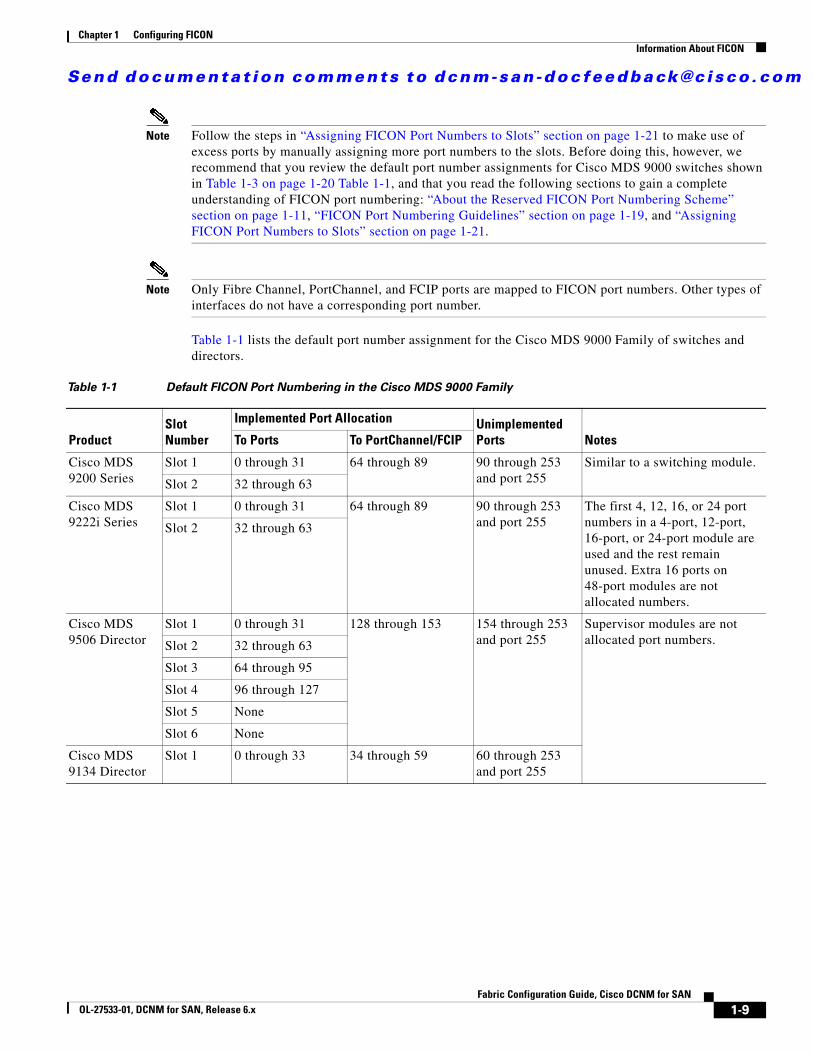
Table 1-1 lists the default port number assignment for the Cisco MDS 9000 Family of switches and directors.
Table 1-1 Default FICON Port Numbering in the Cisco MDS 9000 Family
ProductSlot Number
Implemented Port Allocation Unimplemented Ports NotesTo Ports To PortChannel/FCIP
Cisco MDS 9200 Series
Slot 1 0 through 31 64 through 89 90 through 253 and port 255
Similar to a switching module.
Slot 2 32 through 63
Cisco MDS 9222i Series
Slot 1 0 through 31 64 through 89 90 through 253 and port 255
The first 4, 12, 16, or 24 port numbers in a 4-port, 12-port, 16-port, or 24-port module are used and the rest remain unused. Extra 16 ports on 48-port modules are not allocated numbers.
Slot 2 32 through 63
Cisco MDS 9506 Director
Slot 1 0 through 31 128 through 153 154 through 253 and port 255
Supervisor modules are not allocated port numbers.Slot 2 32 through 63
Slot 3 64 through 95
Slot 4 96 through 127
Slot 5 None
Slot 6 None
Cisco MDS 9134 Director
Slot 1 0 through 33 34 through 59 60 through 253 and port 255
Send documenta t ion comments to dcnm-san -doc feedback@c i sco .com
1-10Fabric Configuration Guide, Cisco DCNM for SAN
OL-27533-01, DCNM for SAN, Release 6.x
Chapter 1 Configuring FICONInformation About FICON
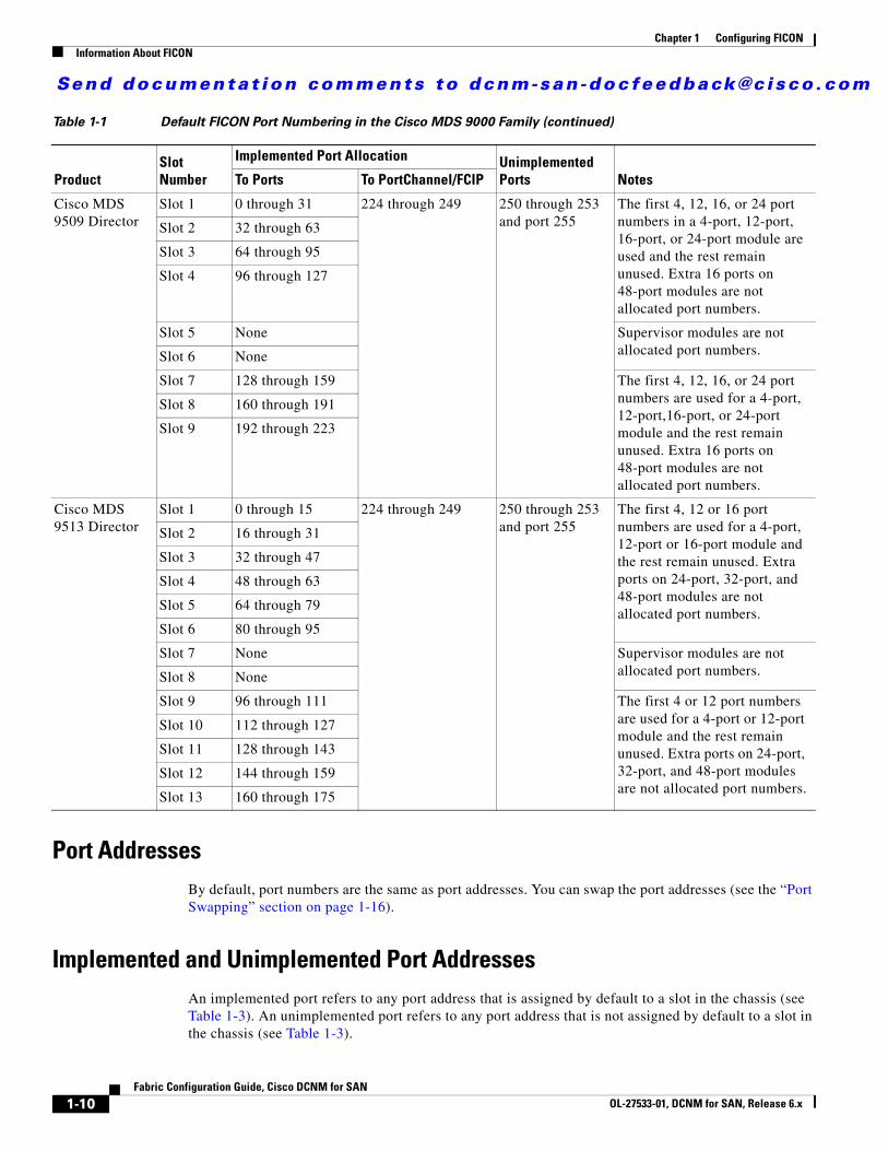
Port AddressesBy default, port numbers are the same as port addresses. You can swap the port addresses (see the “Port Swapping” section on page 1-16).
Implemented and Unimplemented Port Addresses An implemented port refers to any port address that is assigned by default to a slot in the chassis (see Table 1-3). An unimplemented port refers to any port address that is not assigned by default to a slot in the chassis (see Table 1-3).
Cisco MDS 9509 Director
Slot 1 0 through 31 224 through 249 250 through 253 and port 255
The first 4, 12, 16, or 24 port numbers in a 4-port, 12-port, 16-port, or 24-port module are used and the rest remain unused. Extra 16 ports on 48-port modules are not allocated port numbers.
Slot 2 32 through 63
Slot 3 64 through 95
Slot 4 96 through 127
Slot 5 None Supervisor modules are not allocated port numbers.Slot 6 None
Slot 7 128 through 159 The first 4, 12, 16, or 24 port numbers are used for a 4-port, 12-port,16-port, or 24-port module and the rest remain unused. Extra 16 ports on 48-port modules are not allocated port numbers.
Slot 8 160 through 191
Slot 9 192 through 223
Cisco MDS 9513 Director
Slot 1 0 through 15 224 through 249 250 through 253 and port 255
The first 4, 12 or 16 port numbers are used for a 4-port, 12-port or 16-port module and the rest remain unused. Extra ports on 24-port, 32-port, and 48-port modules are not allocated port numbers.
Slot 2 16 through 31
Slot 3 32 through 47
Slot 4 48 through 63
Slot 5 64 through 79
Slot 6 80 through 95
Slot 7 None Supervisor modules are not allocated port numbers.Slot 8 None
Slot 9 96 through 111 The first 4 or 12 port numbers are used for a 4-port or 12-port module and the rest remain unused. Extra ports on 24-port, 32-port, and 48-port modules are not allocated port numbers.
Slot 10 112 through 127
Slot 11 128 through 143
Slot 12 144 through 159
Slot 13 160 through 175
Table 1-1 Default FICON Port Numbering in the Cisco MDS 9000 Family (continued)
ProductSlot Number
Implemented Port Allocation Unimplemented Ports NotesTo Ports To PortChannel/FCIP
Send documenta t ion comments to dcnm-san -doc feedback@c i sco .com
1-11Fabric Configuration Guide, Cisco DCNM for SAN
OL-27533-01, DCNM for SAN, Release 6.x
Chapter 1 Configuring FICONInformation About FICON
About the Reserved FICON Port Numbering SchemeA range of 250 port numbers are available for you to assign to all the ports on a switch. Table 1-3 shows that you can have more than 250 physical ports on a switch and the excess ports do not have port numbers in the default numbering scheme. When you have more than 250 physical ports on your switch, you can have ports without a port number assigned if they are not in a FICON VSAN, or you can assign duplicate port numbers if they are not used in the same FICON VSAN. For example, you can configure port number 1 on interface fc1/1 in FICON VSAN 10 and fc10/1 in FICON VSAN 20.
Note A VSAN can have a maximum of 250 port numbers.
Note FICON port numbers are not changed for ports that are active. You must first disable the interfaces using the shutdown command.
Note You can configure port numbers even when no module is installed in the slot.
Installed and Uninstalled PortsAn installed port refers to a port for which all required hardware is present. A specified port number in a VSAN can be implemented, and yet not installed, if any of the following conditions apply:
• The module is not present—For example, if module 1 is not physically present in slot 1 in a Cisco MDS 9509 Director, ports 0 to 31 are considered uninstalled.
• The small form-factor pluggable (SFP) port is not present—For example, if a 16-port module is inserted in slot 2 in a Cisco MDS 9509 Director, ports 48 to 63 are considered uninstalled.
• For slot 1, ports 0 to 31, or 0 to 15 have been assigned. Only the physical port fc1/5 with port number 4 is in VSAN 2. The rest of the physical ports are not in VSAN 2. The port numbers 0 to 249 are considered implemented for any FICON-enabled VSAN. Therefore, VSAN 2 has port numbers 0 to 249 and one physical port, fc1/4. The corresponding physical ports 0 to 3,and 5 to 249 are not in VSAN 2. When the FICON VSAN port address is displayed, those port numbers with the physical ports not in VSAN 2 are not installed (for example, ports 0 to 3, or 5 to 249).
Another scenario is if VSANs 1 through 5 are FICON-enabled, and trunking-enabled interface fc1/1 has VSANs 3 through 10, then port address 0 is uninstalled in VSAN 1 and 2.
• The port is part of a PortChannel—For example, if interface fc 1/1 is part of PortChanne1 5, port address 0 is uninstalled in all FICON VSANs. See Table 1-3.
About Port Numbers for FCIP and PortChannelFCIP and PortChannels cannot be used in a FICON-enabled VSAN unless they are explicitly bound to a port number.
See the “Configuring FICON Ports” section on page 1-27, “Configuring FICON Ports” section on page 1-27, “Reserving FICON Port Numbers for FCIP and PortChannel Interfaces” section on page 1-21, and “Binding Port Numbers to FCIP Interfaces” section on page 1-28.
Send documenta t ion comments to dcnm-san -doc feedback@c i sco .com
1-12Fabric Configuration Guide, Cisco DCNM for SAN
OL-27533-01, DCNM for SAN, Release 6.x
Chapter 1 Configuring FICONInformation About FICON
You can use the default port numbers if they are available (see Table 1-1 on page 1-9) or if you reserve port numbers from the pool of port numbers that are not reserved for Fibre Channel interfaces (see the “FICON Port Numbering” section on page 1-8 and the “About the Reserved FICON Port Numbering Scheme” section on page 1-11).
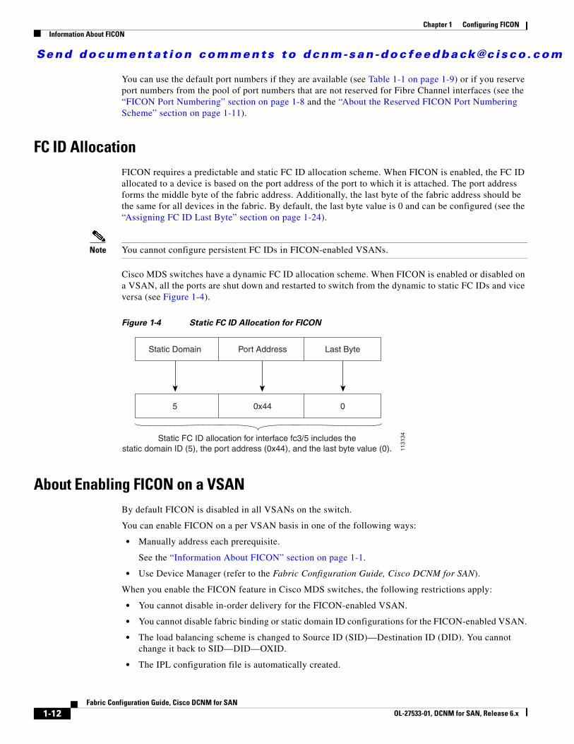
FC ID AllocationFICON requires a predictable and static FC ID allocation scheme. When FICON is enabled, the FC ID allocated to a device is based on the port address of the port to which it is attached. The port address forms the middle byte of the fabric address. Additionally, the last byte of the fabric address should be the same for all devices in the fabric. By default, the last byte value is 0 and can be configured (see the “Assigning FC ID Last Byte” section on page 1-24).
Note You cannot configure persistent FC IDs in FICON-enabled VSANs.
Cisco MDS switches have a dynamic FC ID allocation scheme. When FICON is enabled or disabled on a VSAN, all the ports are shut down and restarted to switch from the dynamic to static FC IDs and vice versa (see Figure 1-4).
Figure 1-4 Static FC ID Allocation for FICON
About Enabling FICON on a VSANBy default FICON is disabled in all VSANs on the switch.
You can enable FICON on a per VSAN basis in one of the following ways:
• Manually address each prerequisite.
See the “Information About FICON” section on page 1-1.
• Use Device Manager (refer to the Fabric Configuration Guide, Cisco DCNM for SAN).
When you enable the FICON feature in Cisco MDS switches, the following restrictions apply:
• You cannot disable in-order delivery for the FICON-enabled VSAN.
• You cannot disable fabric binding or static domain ID configurations for the FICON-enabled VSAN.
• The load balancing scheme is changed to Source ID (SID)—Destination ID (DID). You cannot change it back to SID—DID—OXID.
• The IPL configuration file is automatically created.
Static Domain Port Address Last Byte
5 0x44 0
Static FC ID allocation for interface fc3/5 includes thestatic domain ID (5), the port address (0x44), and the last byte value (0). 11
3134
Send documenta t ion comments to dcnm-san -doc feedback@c i sco .com
1-13Fabric Configuration Guide, Cisco DCNM for SAN
OL-27533-01, DCNM for SAN, Release 6.x
Chapter 1 Configuring FICONInformation About FICON
See the “FICON Configuration Files” section on page 1-15.
Tip Using Device Manager, FICON auto-save can be invoked by multiple users logged on to the same FICON-enabled switch. Device Manager performs a periodic auto-save on any FICON-enabled switch causing increments in the FICON key counter. These increments highlight a change that has actually not occurred. To avoid this situation, we recommend that only one instance of Device Manager monitor a FICON-enabled switch.
FICON Information RefreshWhen viewing FICON information through the Device Manager dialog boxes, you must manually refresh the display by clicking the Refresh button to see the latest updates. You need to take this step whether you configure FICON through the CLI or through the Device Manager.
There is no automatic refresh of FICON information. This information would be refreshed so often that it would affect performance.
About FICON Device AllegianceFICON requires serialization of access among multiple mainframes, CLI, and SNMP sessions be maintained on Cisco MDS 9000 Family switches by controlling device allegiance for the currently executing session. Any other session is denied permission to perform configuration changes unless the required allegiance is available.
Caution This task discards the currently executing session.
Automatically Saving the Running ConfigurationCisco MDS NX-OS provides an option to automatically save any configuration changes to the startup configuration. This ensures that the new configuration is present after a switch reboot. By default, the Active=Saved option is automatically enabled on any FICON VSAN.
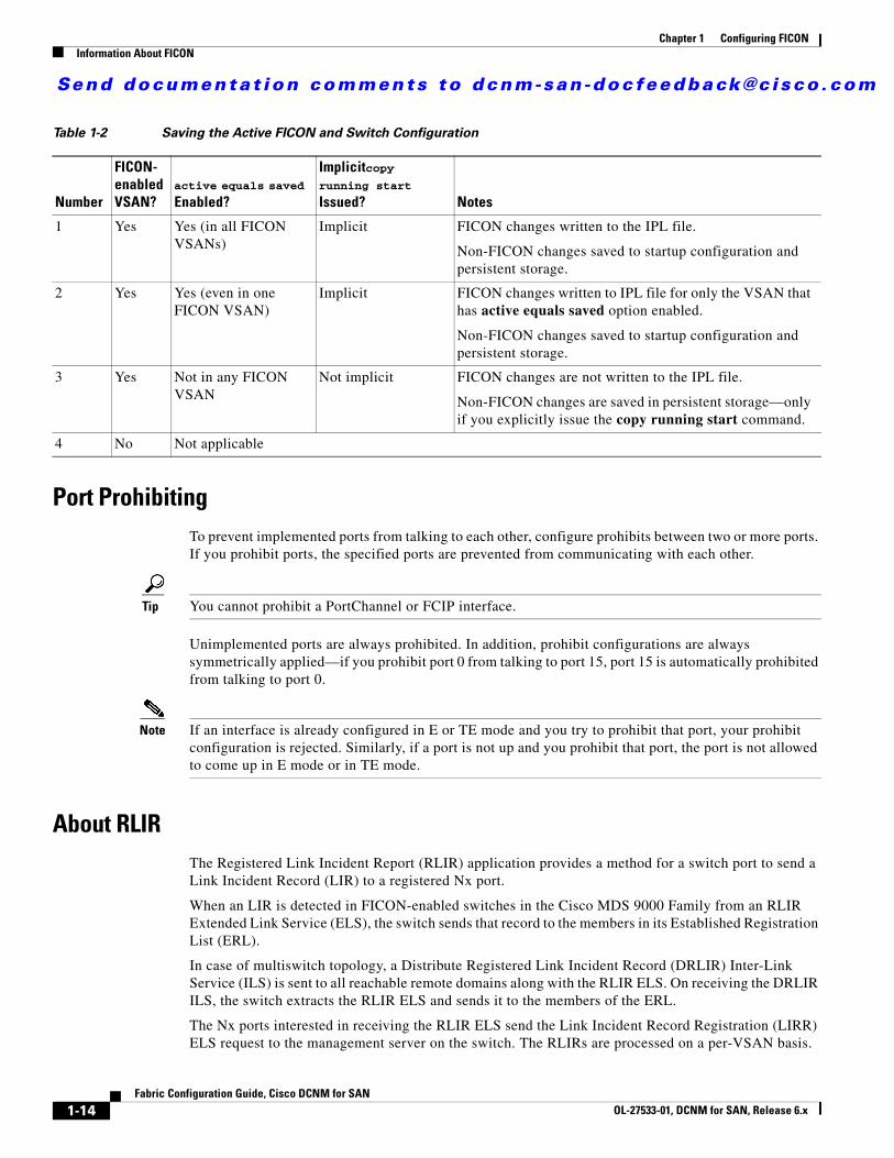
Table 1-2 displays the results of the Active = Saved option and the implicit copy from the running configuration to the startup configuration (copy running start) in various scenarios.
When the Active=Saved option is enabled in any FICON-enabled VSAN in the fabric, then the following apply (see Number 1 and 2 in Table 1-2):
• All configuration changes (FICON-specific or not) are automatically saved to persistent storage (implicit copy running start) and stored in the startup configuration.
• FICON-specific configuration changes are immediately saved to the IPL file (see the “FICON Configuration Files” section on page 1-15).
If the Active=Saved option is not enabled in any FICON-enabled VSAN in the fabric, then FICON-specific configuration changes are not saved in the IPL file and an implicit copy running startup command is not issued, you must explicitly save the running configuration to the startup configuration (see number 3 in Table 1-2).
Send documenta t ion comments to dcnm-san -doc feedback@c i sco .com
1-14Fabric Configuration Guide, Cisco DCNM for SAN
OL-27533-01, DCNM for SAN, Release 6.x
Chapter 1 Configuring FICONInformation About FICON
Port ProhibitingTo prevent implemented ports from talking to each other, configure prohibits between two or more ports. If you prohibit ports, the specified ports are prevented from communicating with each other.
Tip You cannot prohibit a PortChannel or FCIP interface.
Unimplemented ports are always prohibited. In addition, prohibit configurations are always symmetrically applied—if you prohibit port 0 from talking to port 15, port 15 is automatically prohibited from talking to port 0.
Note If an interface is already configured in E or TE mode and you try to prohibit that port, your prohibit configuration is rejected. Similarly, if a port is not up and you prohibit that port, the port is not allowed to come up in E mode or in TE mode.
About RLIRThe Registered Link Incident Report (RLIR) application provides a method for a switch port to send a Link Incident Record (LIR) to a registered Nx port.
When an LIR is detected in FICON-enabled switches in the Cisco MDS 9000 Family from an RLIR Extended Link Service (ELS), the switch sends that record to the members in its Established Registration List (ERL).
In case of multiswitch topology, a Distribute Registered Link Incident Record (DRLIR) Inter-Link Service (ILS) is sent to all reachable remote domains along with the RLIR ELS. On receiving the DRLIR ILS, the switch extracts the RLIR ELS and sends it to the members of the ERL.
The Nx ports interested in receiving the RLIR ELS send the Link Incident Record Registration (LIRR) ELS request to the management server on the switch. The RLIRs are processed on a per-VSAN basis.
Table 1-2 Saving the Active FICON and Switch Configuration
Number
FICON-enabled VSAN?
active equals saved
Enabled?
Implicitcopy running start
Issued? Notes
1 Yes Yes (in all FICON VSANs)
Implicit FICON changes written to the IPL file.
Non-FICON changes saved to startup configuration and persistent storage.
2 Yes Yes (even in one FICON VSAN)
Implicit FICON changes written to IPL file for only the VSAN that has active equals saved option enabled.
Non-FICON changes saved to startup configuration and persistent storage.
3 Yes Not in any FICON VSAN
Not implicit FICON changes are not written to the IPL file.
Non-FICON changes are saved in persistent storage—only if you explicitly issue the copy running start command.
4 No Not applicable
Send documenta t ion comments to dcnm-san -doc feedback@c i sco .com
1-15Fabric Configuration Guide, Cisco DCNM for SAN
OL-27533-01, DCNM for SAN, Release 6.x
Chapter 1 Configuring FICONFICON Configuration Files
The RLIR data is written to persistent storage when you copy the running configuration to the startup configuration.
FICON Configuration FilesYou can save up to 16 FICON configuration files on each FICON-enabled VSAN (in persistent storage). The file format is proprietary to IBM. These files can be read and written by IBM hosts using the in-band CUP protocol. Additionally, you can use the Cisco MDS CLI or DCNM-SAN applications to operate on these FICON configuration files.
Note Multiple FICON configuration files with the same name can exist in the same switch, provided they reside in different VSANs. For example, you can create a configuration file named XYZ in both VSAN 1 and VSAN 3.
When you enable the FICON feature in a VSAN, the switches always use the startup FICON configuration file, called IPL. This file is created with a default configuration as soon as FICON is enabled in a VSAN.
Caution When FICON is disabled on a VSAN, all the FICON configuration files are irretrievably lost.
FICON configuration files contain the following configuration for each implemented port address:
• Block
• Prohibit mask
• Port address name
Note Normal configuration files used by Cisco MDS switches include FICON-enabled attributes for a VSAN, port number mapping for PortChannels and FCIP interfaces, port number to port address mapping, port and trunk allowed VSAN configuration for ports, in-order guarantee, static domain ID configuration, and fabric binding configuration.
Only one user can access the configuration file at any given time:
• If this file is being accessed by user 1, user 2 cannot access this file.
• If user 2 does attempt to access this file, an error is issued to user 2.
• If user 1 is inactive for more than 15 seconds, the file is automatically closed and available for use by any other permitted user.
FICON configuration files can be accessed by any host, SNMP, or CLI user who is permitted to access the switch. The locking mechanism in the Cisco NX-OS software restricts access to one user at a time per file. This lock applies to newly created files and previously saved files. Before accessing any file, you must lock the file and obtain the file key. A new file key is used by the locking mechanism for each lock request. The key is discarded when the lock timeout of 15 seconds expires. The lock timeout value cannot be changed.
Send documenta t ion comments to dcnm-san -doc feedback@c i sco .com
1-16Fabric Configuration Guide, Cisco DCNM for SAN
OL-27533-01, DCNM for SAN, Release 6.x
Chapter 1 Configuring FICONFICON Configuration Files
Port Swapping The FICON port-swapping feature is only provided for maintenance purposes.
The FICON port-swapping feature causes all configurations associated with old-port-number and new port-number to be swapped, including VSAN configurations.
Cisco MDS switches allow port swapping for nonexistent ports as follows:
• Only FICON-specific configurations (prohibit, block, and port address mapping) are swapped.
• No other system configuration is swapped.
• All other system configurations are only maintained for existing ports.
• If you swap a port in a module that has unlimited oversubscription ratios enabled with a port in a module that has limited oversubscription ratios, then you may experience a degradation in bandwidth.
Tip If you check the Active=Saved check box active equals saved is enabled on any FICON VSAN, then the swapped configuration is automatically saved to startup. Otherwise, you must explicitly save the running configuration immediately after swapping the ports.
Once you swap ports, the switch automatically performs the following actions:
• Shuts down both the old and new ports.
• Swaps the port configuration.
If you attempt to bring the port up, you must explicitly shut down the port to resume traffic.
Note To view the latest FICON information, you must click the Refresh button. See the “Automatically Saving the Running Configuration” section on page 1-26.
FICON Tape AccelerationThe sequential nature of tape devices causes each I/O operation to the tape device over an FCIP link to incur the latency of the FCIP link. Throughput drastically decreases as the round-trip time through the FCIP link increases, leading to longer backup windows. Also, after each I/O operation, the tape device is idle until the next I/O arrives. Starting and stopping of the tape head reduces the lifespan of the tape, except when I/O operations are directed to a virtual tape.
Cisco MDS NX-OS software provides acceleration for the following FICON tape write operations:
• The link between mainframe and native tape drives (both IBM and Sun/STK)
• The back-end link between the VSM (Virtual Storage Management) and tape drive (Sun/STK)
FICON tape acceleration over FCIP provides the following advantages:
• Efficiently utilizes the tape device by decreasing idle time
• More sustained throughput as latency increases
• Similar to FCP tape acceleration, and does not conflict with it
Send documenta t ion comments to dcnm-san -doc feedback@c i sco .com
1-17Fabric Configuration Guide, Cisco DCNM for SAN
OL-27533-01, DCNM for SAN, Release 6.x
Chapter 1 Configuring FICONFICON Configuration Files
Note FICON tape read acceleration over FCIP is supported from Cisco MDS NX-OS Release 5.0(1). For more information refer to the “Configuring FICON Tape Read Acceleration” section on page 1-32.
Figure 1-5 through Figure 1-8 show supported configurations.
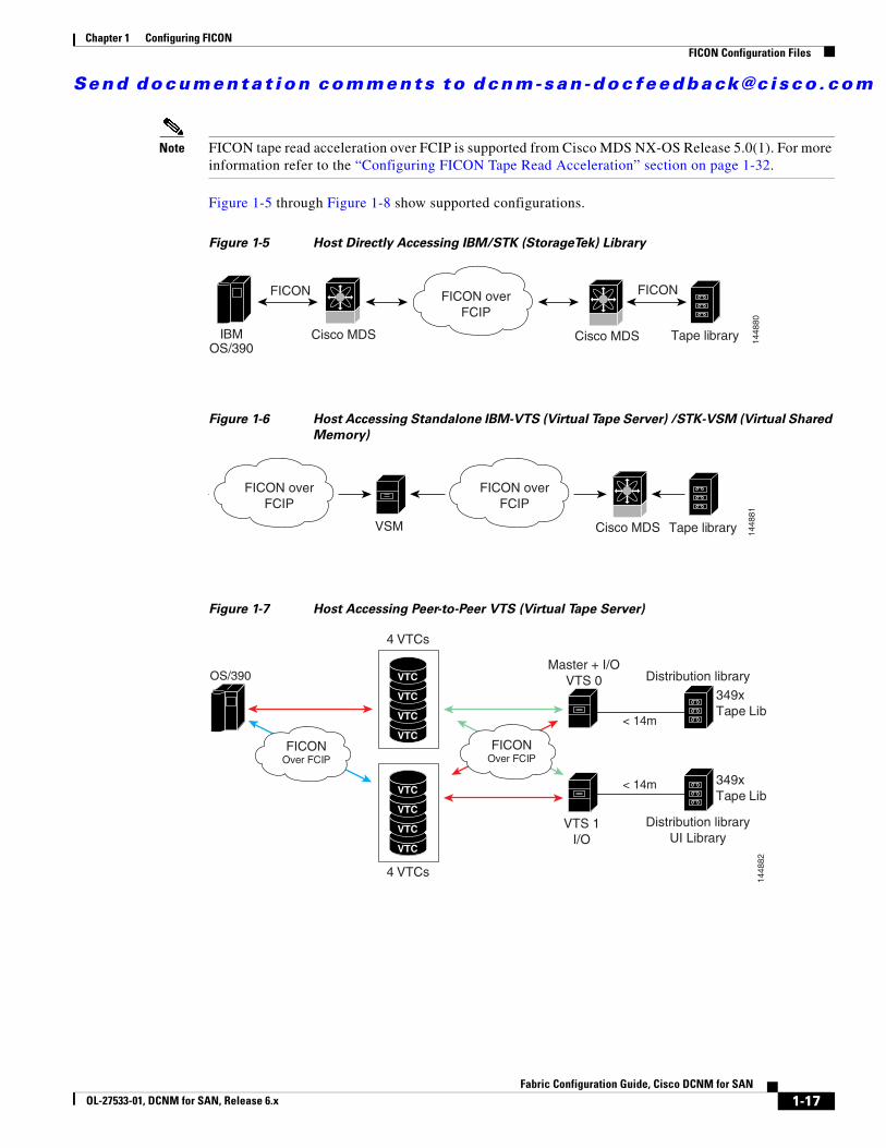
Figure 1-5 Host Directly Accessing IBM/STK (StorageTek) Library
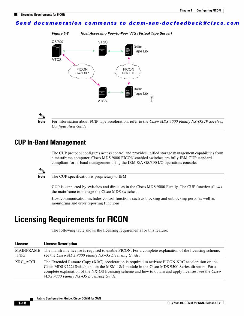
Figure 1-6 Host Accessing Standalone IBM-VTS (Virtual Tape Server) /STK-VSM (Virtual Shared
Memory)
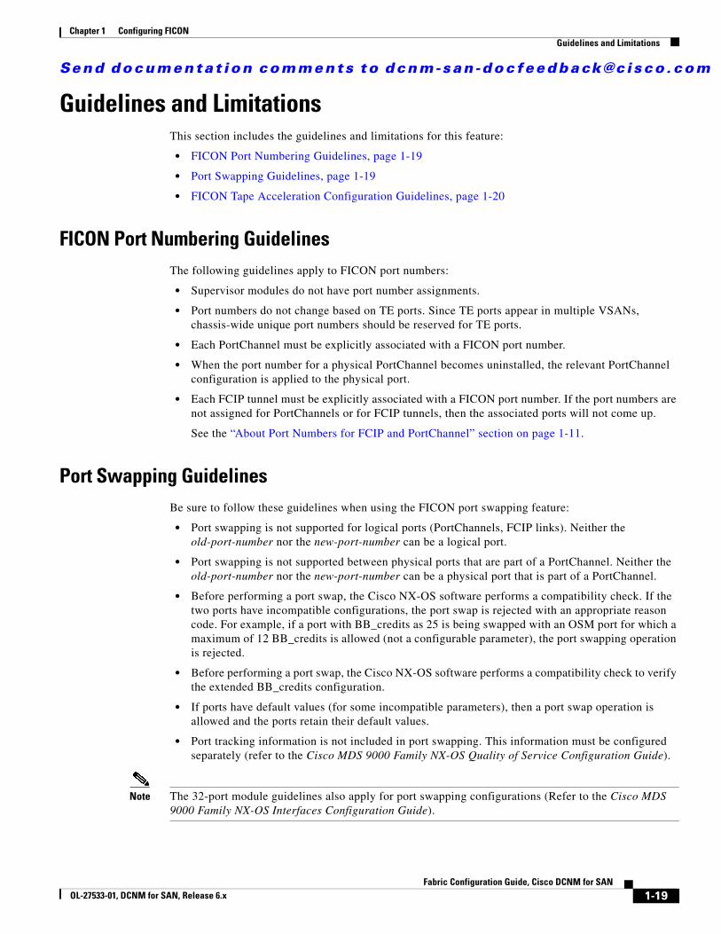
Figure 1-7 Host Accessing Peer-to-Peer VTS (Virtual Tape Server)
IBMOS/390
Tape library
FICON
Cisco MDS Cisco MDS
FICON overFCIP
1448
80
FICON
Tape library
FICON overFCIP
FICON overFCIP
1448
81
VSM Cisco MDS
VTS 1I/O
Master + I/OVTS 0
FICONOver FCIP
FICONOver FCIP
< 14m
< 14m
OS/390
349xTape Lib
349xTape Lib
Distribution libraryUI Library
Distribution library
1448
82
VTC
VTC
VTC
VTC
VTC
VTC
VTC
VTC
4 VTCs
4 VTCs
Send documenta t ion comments to dcnm-san -doc feedback@c i sco .com
1-18Fabric Configuration Guide, Cisco DCNM for SAN
OL-27533-01, DCNM for SAN, Release 6.x
Chapter 1 Configuring FICONLicensing Requirements for FICON
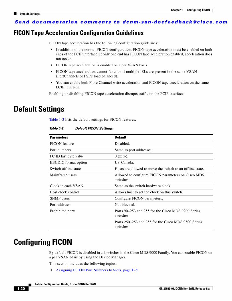
Figure 1-8 Host Accessing Peer-to-Peer VTS (Virtual Tape Server)
Note For information about FCIP tape acceleration, refer to the Cisco MDS 9000 Family NX-OS IP Services Configuration Guide.
CUP In-Band ManagementThe CUP protocol configures access control and provides unified storage management capabilities from a mainframe computer. Cisco MDS 9000 FICON-enabled switches are fully IBM CUP standard compliant for in-band management using the IBM S/A OS/390 I/O operations console.
Note The CUP specification is proprietary to IBM.
CUP is supported by switches and directors in the Cisco MDS 9000 Family. The CUP function allows the mainframe to manage the Cisco MDS switches.
Host communication includes control functions such as blocking and unblocking ports, as well as monitoring and error reporting functions.
Licensing Requirements for FICONThe following table shows the licensing requirements for this feature:
VTSS
VTSS
FICONOver FCIP
FICONOver FCIP
OS/390
349xTape Lib
349xTape Lib
VTCS
1448
83
License License Description
MAINFRAME_PKG
The mainframe license is required to enable FICON. For a complete explanation of the licensing scheme, see the Cisco MDS 9000 Family NX-OS Licensing Guide.
XRC_ACCL The Extended Remote Copy (XRC) acceleration is required to activate FICON XRC acceleration on the Cisco MDS 9222i Switch and on the MSM-18/4 module in the Cisco MDS 9500 Series directors. For a complete explanation of the NX-OS licensing scheme and how to obtain and apply licenses, see the Cisco MDS 9000 Family NX-OS Licensing Guide.
Send documenta t ion comments to dcnm-san -doc feedback@c i sco .com
1-19Fabric Configuration Guide, Cisco DCNM for SAN
OL-27533-01, DCNM for SAN, Release 6.x
Chapter 1 Configuring FICONGuidelines and Limitations
Guidelines and LimitationsThis section includes the guidelines and limitations for this feature:
• FICON Port Numbering Guidelines, page 1-19
• Port Swapping Guidelines, page 1-19
• FICON Tape Acceleration Configuration Guidelines, page 1-20
FICON Port Numbering GuidelinesThe following guidelines apply to FICON port numbers:
• Supervisor modules do not have port number assignments.
• Port numbers do not change based on TE ports. Since TE ports appear in multiple VSANs, chassis-wide unique port numbers should be reserved for TE ports.
• Each PortChannel must be explicitly associated with a FICON port number.
• When the port number for a physical PortChannel becomes uninstalled, the relevant PortChannel configuration is applied to the physical port.
• Each FCIP tunnel must be explicitly associated with a FICON port number. If the port numbers are not assigned for PortChannels or for FCIP tunnels, then the associated ports will not come up.
See the “About Port Numbers for FCIP and PortChannel” section on page 1-11.
Port Swapping GuidelinesBe sure to follow these guidelines when using the FICON port swapping feature:
• Port swapping is not supported for logical ports (PortChannels, FCIP links). Neither the old-port-number nor the new-port-number can be a logical port.
• Port swapping is not supported between physical ports that are part of a PortChannel. Neither the old-port-number nor the new-port-number can be a physical port that is part of a PortChannel.
• Before performing a port swap, the Cisco NX-OS software performs a compatibility check. If the two ports have incompatible configurations, the port swap is rejected with an appropriate reason code. For example, if a port with BB_credits as 25 is being swapped with an OSM port for which a maximum of 12 BB_credits is allowed (not a configurable parameter), the port swapping operation is rejected.
• Before performing a port swap, the Cisco NX-OS software performs a compatibility check to verify the extended BB_credits configuration.
• If ports have default values (for some incompatible parameters), then a port swap operation is allowed and the ports retain their default values.
• Port tracking information is not included in port swapping. This information must be configured separately (refer to the Cisco MDS 9000 Family NX-OS Quality of Service Configuration Guide).
Note The 32-port module guidelines also apply for port swapping configurations (Refer to the Cisco MDS 9000 Family NX-OS Interfaces Configuration Guide).
Send documenta t ion comments to dcnm-san -doc feedback@c i sco .com
1-20Fabric Configuration Guide, Cisco DCNM for SAN
OL-27533-01, DCNM for SAN, Release 6.x
Chapter 1 Configuring FICONDefault Settings
FICON Tape Acceleration Configuration GuidelinesFICON tape acceleration has the following configuration guidelines:
• In addition to the normal FICON configuration, FICON tape acceleration must be enabled on both ends of the FCIP interface. If only one end has FICON tape acceleration enabled, acceleration does not occur.
• FICON tape acceleration is enabled on a per VSAN basis.
• FICON tape acceleration cannot function if multiple ISLs are present in the same VSAN (PortChannels or FSPF load balanced).
• You can enable both Fibre Channel write acceleration and FICON tape acceleration on the same FCIP interface.
Enabling or disabling FICON tape acceleration disrupts traffic on the FCIP interface.
Default SettingsTable 1-3 lists the default settings for FICON features.
Configuring FICONBy default FICON is disabled in all switches in the Cisco MDS 9000 Family. You can enable FICON on a per VSAN basis by using the Device Manager.
This section includes the following topics:
• Assigning FICON Port Numbers to Slots, page 1-21
Table 1-3 Default FICON Settings
Parameters Default
FICON feature Disabled.
Port numbers Same as port addresses.
FC ID last byte value 0 (zero).
EBCDIC format option US-Canada.
Switch offline state Hosts are allowed to move the switch to an offline state.
Mainframe users Allowed to configure FICON parameters on Cisco MDS switches.
Clock in each VSAN Same as the switch hardware clock.
Host clock control Allows host to set the clock on this switch.
SNMP users Configure FICON parameters.
Port address Not blocked.
Prohibited ports Ports 90–253 and 255 for the Cisco MDS 9200 Series switches.
Ports 250–253 and 255 for the Cisco MDS 9500 Series switches.
Send documenta t ion comments to dcnm-san -doc feedback@c i sco .com
1-21Fabric Configuration Guide, Cisco DCNM for SAN
OL-27533-01, DCNM for SAN, Release 6.x
Chapter 1 Configuring FICONConfiguring FICON
• Reserving FICON Port Numbers for FCIP and PortChannel Interfaces, page 1-21
• Enabling FICON on a VSAN, page 1-22
• Manually Enabling FICON on a VSAN, page 1-23
• Deleting FICON VSANs, page 1-23
• Suspending a FICON VSAN, page 1-23
• Configuring the code-page Option, page 1-24
• Assigning FC ID Last Byte, page 1-24
• Allowing the Host to Move the Switch Offline, page 1-25
• Allowing the Host to Change FICON Port Parameters, page 1-25
• Allowing the Host to Control the Timestamp, page 1-25
• Configuring SNMP Control of FICON Parameters, page 1-26
• Automatically Saving the Running Configuration, page 1-26
Assigning FICON Port Numbers to Slots
Caution When you assign, change, or release a port number, the port reloads.
Detailed Steps
To assign FICON port numbers to slots using Device Manager, follow these steps:
Step 1 Click FICON and then select Port Numbers.
You see the FICON port number.
Step 2 Enter the chassis slot port numbers in the Reserved Port Numbers field.
Step 3 Click Apply.
Reserving FICON Port Numbers for FCIP and PortChannel InterfacesYou must reserve port numbers for logical interfaces, such as FCIP and PortChannels, if you plan to use them.
Detailed Steps
To reserve FICON port numbers for FCIP and PortChannel interfaces using Device Manager, follow these steps:
Step 1 Click FICON > Port Numbers.
You see the FICON port numbers dialog box.
Step 2 Click the Logical tab to see the reserved port numbers for the slot.
Send documenta t ion comments to dcnm-san -doc feedback@c i sco .com
1-22Fabric Configuration Guide, Cisco DCNM for SAN
OL-27533-01, DCNM for SAN, Release 6.x
Chapter 1 Configuring FICONConfiguring FICON
Step 3 Enter the chassis slot port numbers. These are the reserved port numbers for one chassis slot. There can be up to 64 port numbers reserved for each slot in the chassis.
Step 4 Click Apply.
Enabling FICON on a VSAN
Detailed Steps
To create a FICON-enabled VSAN, follow these steps:
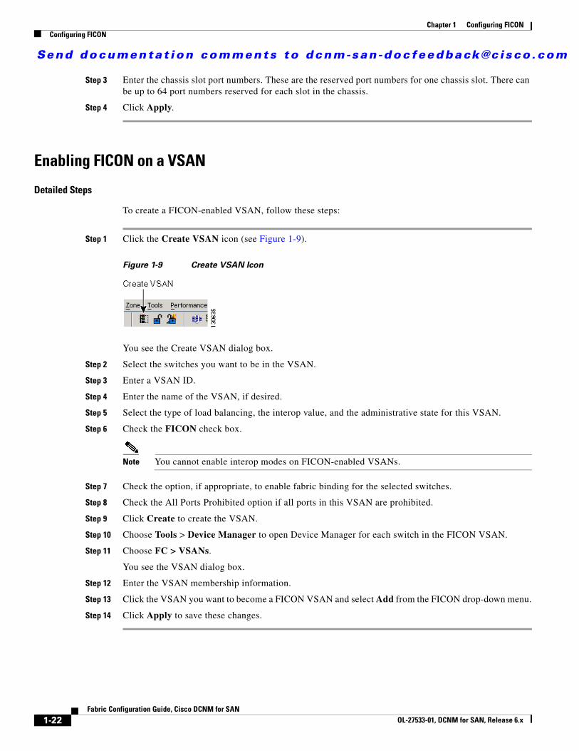
Step 1 Click the Create VSAN icon (see Figure 1-9).
Figure 1-9 Create VSAN Icon
You see the Create VSAN dialog box.
Step 2 Select the switches you want to be in the VSAN.
Step 3 Enter a VSAN ID.
Step 4 Enter the name of the VSAN, if desired.
Step 5 Select the type of load balancing, the interop value, and the administrative state for this VSAN.
Step 6 Check the FICON check box.
Note You cannot enable interop modes on FICON-enabled VSANs.
Step 7 Check the option, if appropriate, to enable fabric binding for the selected switches.
Step 8 Check the All Ports Prohibited option if all ports in this VSAN are prohibited.
Step 9 Click Create to create the VSAN.
Step 10 Choose Tools > Device Manager to open Device Manager for each switch in the FICON VSAN.
Step 11 Choose FC > VSANs.
You see the VSAN dialog box.
Step 12 Enter the VSAN membership information.
Step 13 Click the VSAN you want to become a FICON VSAN and select Add from the FICON drop-down menu.
Step 14 Click Apply to save these changes.
Send documenta t ion comments to dcnm-san -doc feedback@c i sco .com
1-23Fabric Configuration Guide, Cisco DCNM for SAN
OL-27533-01, DCNM for SAN, Release 6.x
Chapter 1 Configuring FICONConfiguring FICON
Manually Enabling FICON on a VSAN
Note This section describes the procedure to manually enable FICON on a VSAN. If you have already enabled FICON on the required VSAN using the automated setup (recommended), skip to the “Automatically Saving the Running Configuration” section on page 1-26.
Detailed Steps
To manually enable FICON on a VSAN, follow these steps:
Step 1 Choose VSAN > FICON.
You see the FICON VSAN configuration information in the Information pane.
Step 2 Select the switch in the VSAN on which you want to enable FICON.
Step 3 Click enable from the Command drop-down menu.
Step 4 Click the Apply Changes icon to save these changes.
Deleting FICON VSANs
Detailed Steps
To delete a FICON VSAN, follow these steps:
Step 1 Select All VSANS.
You see the VSAN table in the Information pane.
Step 2 Click anywhere in the row of the VSAN that you want to delete.
Step 3 Click Delete Row to delete the VSAN.
Note Deleting the VSAN will also delete the associated FICON configuration file, and the file cannot be recovered.
Suspending a FICON VSAN
Detailed Steps
To suspend a FICON VSAN, follow these steps:
Step 1 Click All VSANs.
You see all the VSANs listed in the Information pane.
Send documenta t ion comments to dcnm-san -doc feedback@c i sco .com
1-24Fabric Configuration Guide, Cisco DCNM for SAN
OL-27533-01, DCNM for SAN, Release 6.x
Chapter 1 Configuring FICONConfiguring FICON
Step 2 Select the VSAN that you want to suspend.
Step 3 Set the Admin drop-down menu for a VSAN to suspended.
Step 4 Click the Apply Changes icon to save these changes.
Note This command can be issued by the host if the host is allowed to do so (see the “Allowing the Host to Move the Switch Offline” section on page 1-25).
Configuring the code-page OptionFICON strings are coded in Extended Binary-Coded Decimal Interchange Code (EBCDIC) format. Refer to your mainframe documentation for details on the code-page options.
Cisco MDS switches support international-5, france, brazil, germany, italy, japan, spain-latinamerica, uk, and us-canada (default) EBCDIC format options.
Detailed Steps
To modify the code-page option using Device Manager, follow these steps:
Step 1 Choose FICON > VSANs.
You see the FICON VSAN configuration dialog box. The VSANs tab is the default tab.
Step 2 From the CodePage drop-down menu, choose an option for the FICON VSAN you want to configure.
Step 3 Click Apply to save the changes.
Assigning FC ID Last Byte
Restrictions
If the FICON feature is configured in cascaded mode, the Cisco MDS switches use ISLs to connect to other switches.
Detailed Steps
To assign the last byte for the FC ID, follow these steps:
Step 1 Choose All VSANs > Domain Manager.
Step 2 Click the Persistent FCIDs tab.
Step 3 Select single in the Mask column and then assign the entire FC ID at once. The single option allows you to enter the FC ID in the ###### format.
Step 4 Click the Apply Changes icon to save these changes.
Send documenta t ion comments to dcnm-san -doc feedback@c i sco .com
1-25Fabric Configuration Guide, Cisco DCNM for SAN
OL-27533-01, DCNM for SAN, Release 6.x
Chapter 1 Configuring FICONConfiguring FICON
Allowing the Host to Move the Switch OfflineBy default, hosts are allowed to move the switch to an offline state. To do this, the host sends a "Set offline" command (x'FD') to the CUP.
Detailed Steps
To allow the host (mainframe) to move the switch to an offline state, follow these steps:
Step 1 Choose VSAN > FICON.
You see a list of switches under the Control tab in the Information pane.
Step 2 Click the VSANs tab.
You see the FICON VSAN configuration information in the Information pane.
Step 3 Check the Host Can Offline Sw check box to allow the mainframe to move a switch to the offline state.
Step 4 Check the Host Can Sync Time check box to allow the mainframe to set the system time on the switch.
Step 5 Click the Apply Changes icon to save the changes.
Allowing the Host to Change FICON Port ParametersBy default, mainframe users are not allowed to configure FICON parameters on Cisco MDS switches—they can only query the switch.
Detailed Steps
To allow the host (mainframe) to configure FICON parameters on the Cisco MDS switch, follow these steps:
Step 1 Choose VSAN > FICON.
You see a list of switches under the Control tab in the Information pane.
Step 2 Click the VSANs tab.
You see the FICON VSAN configuration information in the Information pane.
Step 3 Check the Port Control By Host check box to allow the mainframe to control a switch.
Step 4 Click the Apply Changes icon to save the changes.
Allowing the Host to Control the Timestamp By default, the clock in each VSAN is the same as the switch hardware clock. Each VSAN in a Cisco MDS 9000 Family switch represents a virtual director. The clock and time present in each virtual director can be different.To maintain separate clocks for each VSAN, the Cisco NX-OS software maintains the difference of the VSAN-specific clock and the hardware-based director clock. When a host (mainframe)
Send documenta t ion comments to dcnm-san -doc feedback@c i sco .com
1-26Fabric Configuration Guide, Cisco DCNM for SAN
OL-27533-01, DCNM for SAN, Release 6.x
Chapter 1 Configuring FICONConfiguring FICON
sets the time, the Cisco NX-OS software updates this difference between the clocks. When a host reads the clock, it computes the difference between the VSAN-clock and the current director hardware clock and presents a value to the mainframe.
Detailed Steps
To configure host (mainframe) control for the VSAN time stamp, follow these steps:
Step 1 Choose VSAN > FICON.
You see a list of switches under the Control tab in the Information pane.
Step 2 Click the VSANs tab.
You see the FICON VSAN configuration information in the Information pane.
Step 3 Check the Host Can Sync Time checkbox to allow the mainframe to set the system time on the switch.
Step 4 Click the Apply Changes icon to save these changes.
Configuring SNMP Control of FICON ParametersBy default, SNMP users can configure FICON parameters using Cisco DCNM for SAN.
Restrictions
If you disable SNMP in the Cisco MDS switch, you cannot configure FICON parameters using DCNM-SAN.
Detailed Steps
To configure SNMP control of FICON parameters, follow these steps:
Step 1 Choose VSAN > FICON.
You see a list of switches under the Control tab in the Information pane.
Step 2 Click the VSANs tab.
You see the FICON VSAN configuration information in the Information pane.
Step 3 Check the Port Control By SNMP checkbox to allow SNMP users to configure FICON on the switch.
Step 4 Click the Apply Changes icon to save these changes.
Automatically Saving the Running Configuration
Detailed Steps
To save the running configuration, follow these steps:
Send documenta t ion comments to dcnm-san -doc feedback@c i sco .com
1-27Fabric Configuration Guide, Cisco DCNM for SAN
OL-27533-01, DCNM for SAN, Release 6.x
Chapter 1 Configuring FICONConfiguring FICON Ports
Step 1 Choose VSAN > FICON.
You see a list of switches under the Control tab in the Information pane.
Step 2 Click the VSANs tab.
You see the FICON VSAN configuration information in the Information pane.
Step 3 Check the Active=Saved check box to automatically save the running configuration to the startup configuration whenever there is a FICON configuration change.
Step 4 Click the Apply Changes icon to save these changes.
Configuring FICON PortsYou can perform FICON configurations on a per-port address basis in the Cisco MDS 9000 Family switches.
Even if a port is uninstalled, the port address-based configuration is accepted by the Cisco MDS switch. This configuration is applied to the port when the port becomes installed.
This section includes the following topics:
• Binding Port Numbers to PortChannels, page 1-27
• Binding Port Numbers to FCIP Interfaces, page 1-28
• Configuring Port Blocking, page 1-28
• Assigning a Port Address Name, page 1-29
• Specifying an RLIR Preferred Host, page 1-29
• Applying the Saved Configuration Files to the Running Configuration, page 1-30
• Editing FICON Configuration Files, page 1-30
• Copying FICON Configuration Files, page 1-30
• Swapping Ports, page 1-31
• Configuring FICON Tape Acceleration, page 1-31
• Configuring FICON Tape Read Acceleration, page 1-32
• Configuring XRC Acceleration, page 1-32
• Placing CUPs in a Zone, page 1-32
• Calculating FICON Flow Load Balance, page 1-33
• Receiving FICON Alerts, page 1-33
Binding Port Numbers to PortChannels
Caution All port number assignments to PortChannels or FCIP interfaces are lost (cannot be retrieved) when FICON is disabled on all VSANs.
You can bind (or associate) a PortChannel with a FICON port number to bring up that interface.
Send documenta t ion comments to dcnm-san -doc feedback@c i sco .com
1-28Fabric Configuration Guide, Cisco DCNM for SAN
OL-27533-01, DCNM for SAN, Release 6.x
Chapter 1 Configuring FICONConfiguring FICON Ports
Binding Port Numbers to FCIP Interfaces You can bind (or associate) an FCIP interface with a FICON port number to bring up that interface.
Configuring Port BlockingIf you block a port, the port is retained in the operationally down state. If you unblock a port, a port initialization is attempted. When a port is blocked, data and control traffic are not allowed on that port.
Physical Fibre Channel port blocks will continue to transmit an Off-line state (OLS) primitive sequence on a blocked port.
Note The shutdown/no shutdown port state is independent of the block/no block port state.
Restrictions
You cannot block or prohibit the CUP port (0XFE). If a port is shut down, unblocking that port does not initialize the port.
Detailed Steps
To block or unblock port addresses in a VSAN using Device Manager, follow these steps:
Step 1 Choose FICON > VSANs.
Step 2 Select a VSAN ID and click Port Configuration.
You see the FICON Port Configuration dialog box for the selected VSAN.
Step 3 Check the Blocked check box for the port that you want to block.
Step 4 Click Apply to save the changes.
Configuring the Default State for Port ProhibitingBy default, port prohibiting is disabled on the implemented interfaces on the switch. As of Cisco MDS SAN-OS Release 3.0(2), you can change the default port prohibiting state to enabled in VSANs that you create and then selectively disable port prohibiting on implemented ports, if desired. Also, only the FICON configuration files created after you change the default have the new default setting (see the “FICON Configuration Files” section on page 1-15).
Configuring Port Prohibiting
Detailed Steps
To prohibit port addresses in a VSAN using Device Manager, follow these steps:
Step 1 Choose FICON > VSANs.
Send documenta t ion comments to dcnm-san -doc feedback@c i sco .com
1-29Fabric Configuration Guide, Cisco DCNM for SAN
OL-27533-01, DCNM for SAN, Release 6.x
Chapter 1 Configuring FICONConfiguring FICON Ports
Step 2 Select a VASAN ID and click Port Configuration.
You see the FICON Port Configuration dialog box.
Step 3 Set the port prohibit configuration for the selected FICON VSANs.
Step 4 Click Apply to save these changes.
Assigning a Port Address Name
Note To view the latest FICON information, you must click the Refresh button. See the “Automatically Saving the Running Configuration” section on page 1-26.
Detailed Steps
To assign a port address name in Device Manager, follow these steps:
Step 1 Choose FICON > VSANs.
Step 2 Select a VSAN ID and click Port Configuration.
You see the FICON Port Configuration dialog box.
Step 3 Enter the Port Configuration information.
Step 4 Click Apply to save the configuration information.
Specifying an RLIR Preferred HostAs of Cisco MDS SAN-OS Release 3.0(3), you can specify a preferred host to receive RLIR frames. The MDS switch sends RLIR frames to the preferred host only if it meets the following conditions:
• No host in the VSAN is registered for RLIR with the registration function set to “always receive.” If one or more hosts in the VSAN are registered as “always receive,” then RLIR sends only to these hosts and not to the configured preferred host.
• The preferred host is registered with the registration function set to “conditionally receive.”
Note If all registered hosts have the registration function set to “conditionally receive,” then the preferred host receives the RLIR frames.
You can specify only one RLIR preferred host per VSAN. By default, the switch sends RLIR frames to one of the hosts in the VSAN with the register function set to “conditionally receive” if no hosts have the register function set to “always receive.”
Send documenta t ion comments to dcnm-san -doc feedback@c i sco .com
1-30Fabric Configuration Guide, Cisco DCNM for SAN
OL-27533-01, DCNM for SAN, Release 6.x
Chapter 1 Configuring FICONConfiguring FICON Ports
Applying the Saved Configuration Files to the Running Configuration
Detailed Steps
To apply the saved configuration files to the running configuration using Device Manager, follow these steps:
Step 1 Choose FICON > VSANs.
Step 2 Click the Files tab.
You see the FICON Files dialog box.
Step 3 Highlight the file you want to apply and click Apply File to apply the configuration to the running configuration.
Editing FICON Configuration FilesThe configuration file submode allows you to create and edit FICON configuration files. If a specified file does not exist, it is created. Up to 16 files can be saved. Each file name is restricted to eight alphanumeric characters.
Note To view the latest FICON information, you must click the Refresh button. See the “Automatically Saving the Running Configuration” section on page 1-26.
Detailed Steps
To edit the contents of a specified FICON configuration file using Device Manager, follow these steps:
Step 1 Choose FICON > VSANs.
Step 2 Click the Files tab.
You see the FICON VSANs dialog box.
Step 3 Select a VSAN ID and then click Open to edit the FICON configuration file.
Step 4 Select a VSAN ID and then click Delete to delete the FICON configuration file.
Step 5 Click Apply to apply the changed FICON configuration file.
Copying FICON Configuration Files
Detailed Steps
To copy an existing FICON configuration file using Device Manager, follow these steps:
Step 1 Choose FICON > VSANs.
Send documenta t ion comments to dcnm-san -doc feedback@c i sco .com
1-31Fabric Configuration Guide, Cisco DCNM for SAN
OL-27533-01, DCNM for SAN, Release 6.x
Chapter 1 Configuring FICONConfiguring FICON Ports
Step 2 Click the Files tab.
You see the FICON VSANs dialog box.
Step 3 Click Create to create a FICON configuration file.
You see the Create FICON VSANs Files dialog box.
a. Select a VSAN ID for the FICON VSAN you want to configure.
b. Enter the file name and the description.
c. Click Create to create the file.
Step 4 Click Copy to copy the file to a new file.
Step 5 Click Apply to apply the FICON configuration file.
Swapping Ports
Detailed Steps
To swap ports using Device Manager, follow these steps:
Step 1 Select two Fibre Channel ports by holding down the CTRL key and clicking them.
Step 2 Choose FICON > Swap Selected Ports.
Configuring FICON Tape Acceleration
Detailed Steps
To configure FICON tape acceleration over FCIP, follow these steps:
Step 1 Expand ISL and then select FCIP in the Physical Attributes pane.
Step 2 Click the Tunnels tab in the Information pane.
You see a list of available switches.
Step 3 Click the Create Row icon to create an FCIP tunnel.
You see the Create FCIP Tunnel dialog box.
Step 4 Configure the tunnel with the options.
Step 5 Check the TapeAccelerator check box to enable FICON tape acceleration over this FCIP tunnel.
Step 6 Click Create.
Send documenta t ion comments to dcnm-san -doc feedback@c i sco .com
1-32Fabric Configuration Guide, Cisco DCNM for SAN
OL-27533-01, DCNM for SAN, Release 6.x
Chapter 1 Configuring FICONConfiguring FICON Ports
Configuring FICON Tape Read AccelerationAll the configuration guidelines and restrictions applicable for FICON tape acceleration are also applicable for FICON tape read acceleration. Both FICON tape acceleration and FICON tape read acceleration can coexist.
Configuring XRC AccelerationIBM z/OS Global Mirror eXtended Remote Copy (XRC) is supported on the MSM-18+4 modules. For XRC to function, XRC acceleration must be enabled on the FCIP tunnel interfaces on both ends. XRC acceleration is disabled by default.
Restrictions
XRC acceleration and FICON tape acceleration cannot be enabled on the same FCIP tunnel interface and cannot exist in the same VSAN.
Detailed Steps
To configure XRC acceleration on a FCIP tunnel interface, follow these steps:
Step 1 Expand ISL and then select FCIP in the Physical Attributes pane.
Step 2 Click the Tunnels(Advanced) tab in the Information pane.
You see a list of available FCIP interfaces.
Step 3 Check the check box in the XRC Emulator column to enable XRC acceleration over the FCIP tunnel.
Step 4 Click Apply.
To configure XRC acceleration on an FCIP tunnel interface using Device Manager, follow these steps:
Step 1 In the Device Manager window, click IP and then select FCIP from the menu.
Step 2 Click the Tunnels(Advanced) tab in the Information pane.
You see a list of FCIP interfaces.
Step 3 Check the check box in the XRC Emulator column to enable XRC acceleration over the FCIP tunnel.
Step 4 Click Apply.
Placing CUPs in a Zone
Detailed Steps
To place the CUP in a zone, follow these steps:
Send documenta t ion comments to dcnm-san -doc feedback@c i sco .com
1-33Fabric Configuration Guide, Cisco DCNM for SAN
OL-27533-01, DCNM for SAN, Release 6.x
Chapter 1 Configuring FICONConfiguring FICON Ports
Step 1 In DCNM-SAN, choose Zone > Edit Full Zoneset, and then choose Edit > Edit Default Zone Attributes to set the default zone to permit for the required VSAN.
Step 2 In Device Manager, choose FC > Name Server... for the required VSAN and obtain the FICON:CUP WWN.
Note If more than one FICON:CUP WWN exists in this fabric, be sure to add all the FICON:CUP pWWNs to the required zone.
Step 3 In DCNM-SAN, choose Zone > Edit Full Zoneset and add the FICON:CUP pWWN to the zone database.
Calculating FICON Flow Load BalanceThe FICON Flow Load Balance Calculator allows you to get the best load balancing configuration for your FICON flows. The calculator does not rely on any switch or flow discovery in the fabric. It is available from the DCNM-SAN Tools menu.
Detailed Steps
To use the FICON Flow Load Balance Calculator, follow these steps:
Step 1 Choose Tools > Flow Load Balance Calculator.
You see the Flow Load Balance Calculator.
Step 2 Click Add to enter the source and destination(s) flows.
Step 3 Enter source and destination using 2 byte hex (by domain and area IDs).You can copy and paste these IDs, and then edit them if required.
Step 4 Enter (or select) the number of ISLs between the two switches (for example, between domain ID 0a and 0b).
Step 5 Select a row to remove it and click Remove.
Step 6 Select the module for which you are calculating the load balance.
Step 7 Click Calculate to show the recommended topology.
Note If you change flows or ISLs, you must click Calculate to see the new recommendation.
Receiving FICON AlertsTo receive an alert to indicate any changes in the FICON configuration using Device Manager, follow these steps:
Send documenta t ion comments to dcnm-san -doc feedback@c i sco .com
1-34Fabric Configuration Guide, Cisco DCNM for SAN
OL-27533-01, DCNM for SAN, Release 6.x
Chapter 1 Configuring FICONVerifying FICON Configuration
Step 1 Choose FICON > VSANs.
You see the FICON VSANs dialog box.
Step 2 Check the User Alert Mode check box to receive an alert when the FICON configuration changes.
Step 3 Click Apply to apply this change.
Verifying FICON ConfigurationThis section includes the following topics:
• Viewing ESCON Style Ports, page 1-34
• Displaying RLIR Information, page 1-35
• Displaying FICON Configuration Files, page 1-35
• Displaying XRC Acceleration Statistics, page 1-35
• Displaying FICON Port Address Information, page 1-36
• Displaying IPL File Information, page 1-36
• Viewing the History Buffer, page 1-36
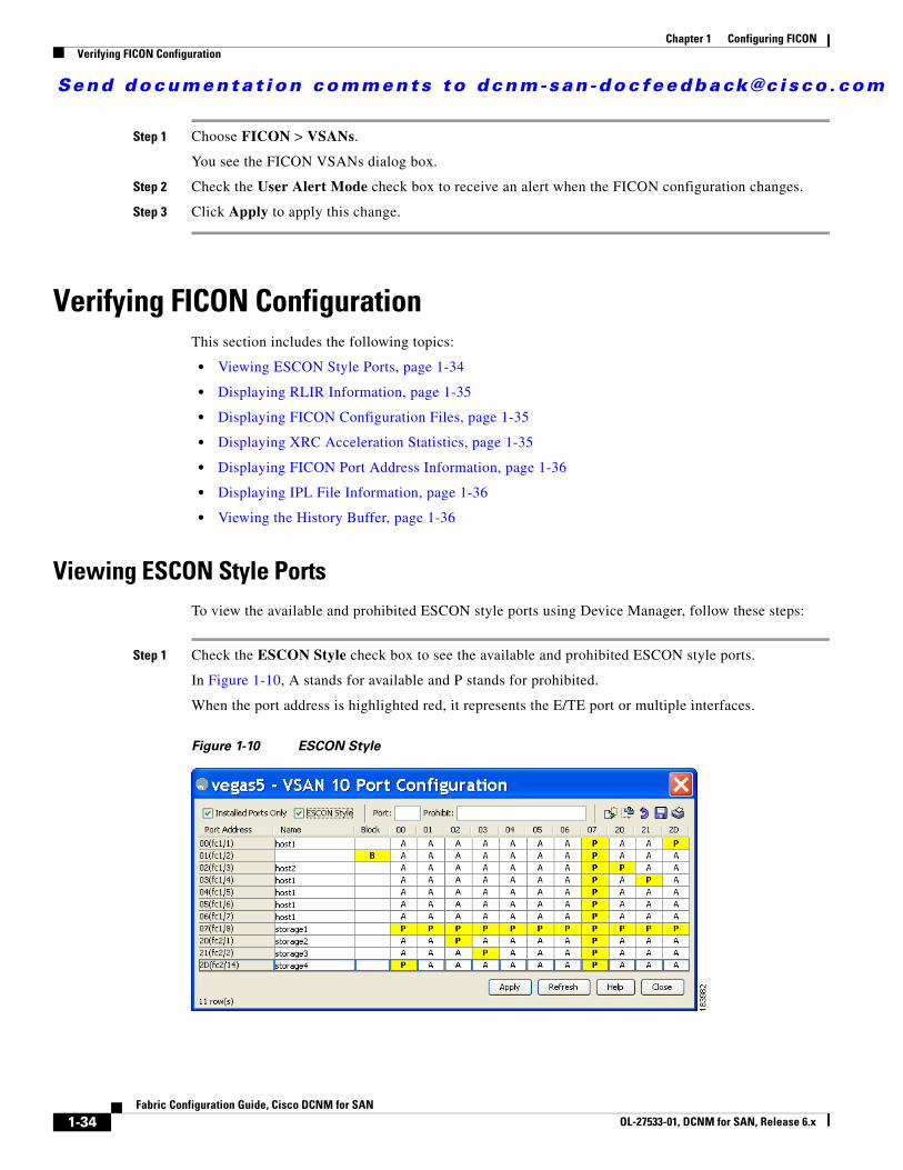
Viewing ESCON Style PortsTo view the available and prohibited ESCON style ports using Device Manager, follow these steps:
Step 1 Check the ESCON Style check box to see the available and prohibited ESCON style ports.
In Figure 1-10, A stands for available and P stands for prohibited.
When the port address is highlighted red, it represents the E/TE port or multiple interfaces.
Figure 1-10 ESCON Style
Send documenta t ion comments to dcnm-san -doc feedback@c i sco .com
1-35Fabric Configuration Guide, Cisco DCNM for SAN
OL-27533-01, DCNM for SAN, Release 6.x
Chapter 1 Configuring FICONVerifying FICON Configuration
Step 2 Click Apply to save the changes.
Displaying RLIR InformationTo view RLIR information using Device Manager, follow these steps:
Step 1 Choose FICON > RLIR ERL.
You see the Show RLIR ERL dialog box.
Step 2 Click Close to close the dialog box.
Displaying FICON Configuration Files
To open and view configuration files in DCNM-SAN, follow these steps:
Step 1 Choose FICON > VSAN.
You see the FICON configuration table in the Information pane.
Step 2 Click the Files tab.
Step 3 Select the file you want to open.
Step 4 Click Open.
Displaying XRC Acceleration StatisticsTo display XRC acceleration statistics, follow these steps:
Step 1 Expand ISL and then select FCIP in the Physical Attributes pane.
Step 2 Click the XRC Statistics tab in the Information pane.
You see the XRC session statistics.
To display XRC acceleration statistics using Device Manager, follow these steps:
Step 1 In the Device Manager window, click IP, and then select FCIP from the menu.
Step 2 Click the XRC Statistics tab in the Information pane.
You see the XRC session statistics.
Send documenta t ion comments to dcnm-san -doc feedback@c i sco .com
1-36Fabric Configuration Guide, Cisco DCNM for SAN
OL-27533-01, DCNM for SAN, Release 6.x
Chapter 1 Configuring FICONVerifying FICON Configuration
Displaying FICON Port Address Information
To display FICON port address information using Device Manager, follow these steps:
Step 1 Choose FICON > VSANs.
You see the FICON VSANs dialog box.
Step 2 Select a VSAN ID and click Port Configuration.
You see the FICON Port Configuration dialog box.
Step 3 Click Close to close the dialog box.
Displaying IPL File InformationTo display the IPL file information using Device Manager, follow these steps:
Step 1 Select VSANs from the FICON menu.
Step 2 Click the Files tab.
You see the FICON VSANs dialog box.
Step 3 Select the file that you want to view and click Open.
Viewing the History BufferIn the directory history buffer, the Key Counter column displays the 32-bit value maintained by Cisco MDS switches. This value is incremented when any port changes state in that VSAN. The key counter (a 32-bit value) is incremented when a FICON-related configuration is changed. Host programs can increment this value at the start of the channel program and then perform operations on multiple ports. The director history buffer keeps a log of which port address configuration was changed for each key-counter value.
The director history buffer provides a mechanism to determine the change in the port state from the previous time when a value was contained in the key counter.
To view the directory history buffer using Device Manager, follow these steps:
Step 1 Choose FICON > VSANs.
You see the FICON VSANs dialog box.
Step 2 Click the Director History button.
You see the history buffer dialog box.
Step 3 Click Close to close the dialog box.
Send documenta t ion comments to dcnm-san -doc feedback@c i sco .com
1-37Fabric Configuration Guide, Cisco DCNM for SAN
OL-27533-01, DCNM for SAN, Release 6.x
Chapter 1 Configuring FICONField Descriptions for FICON
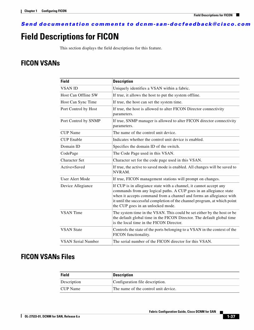
Field Descriptions for FICONThis section displays the field descriptions for this feature.
FICON VSANs
FICON VSANs Files
Field Description
VSAN ID Uniquely identifies a VSAN within a fabric.
Host Can Offline SW If true, it allows the host to put the system offline.
Host Can Sync Time If true, the host can set the system time.
Port Control by Host If true, the host is allowed to alter FICON Director connectivity parameters.
Port Control by SNMP If true, SNMP manager is allowed to alter FICON director connectivity parameters.
CUP Name The name of the control unit device.
CUP Enable Indicates whether the control unit device is enabled.
Domain ID Specifies the domain ID of the switch.
CodePage The Code Page used in this VSAN.
Character Set Character set for the code page used in this VSAN.
Active=Saved If true, the active to saved mode is enabled. All changes will be saved to NVRAM.
User Alert Mode If true, FICON management stations will prompt on changes.
Device Allegiance If CUP is in allegiance state with a channel, it cannot accept any commands from any logical paths. A CUP goes in an allegiance state when it accepts command from a channel and forms an allegiance with it until the successful completion of the channel program, at which point the CUP goes in an unlocked mode.
VSAN Time The system time in the VSAN. This could be set either by the host or be the default global time in the FICON Director. The default global time is the local time in the FICON Director.
VSAN State Controls the state of the ports belonging to a VSAN in the context of the FICON functionality.
VSAN Serial Number The serial number of the FICON director for this VSAN.
Field Description
Description Configuration file description.
CUP Name The name of the control unit device.
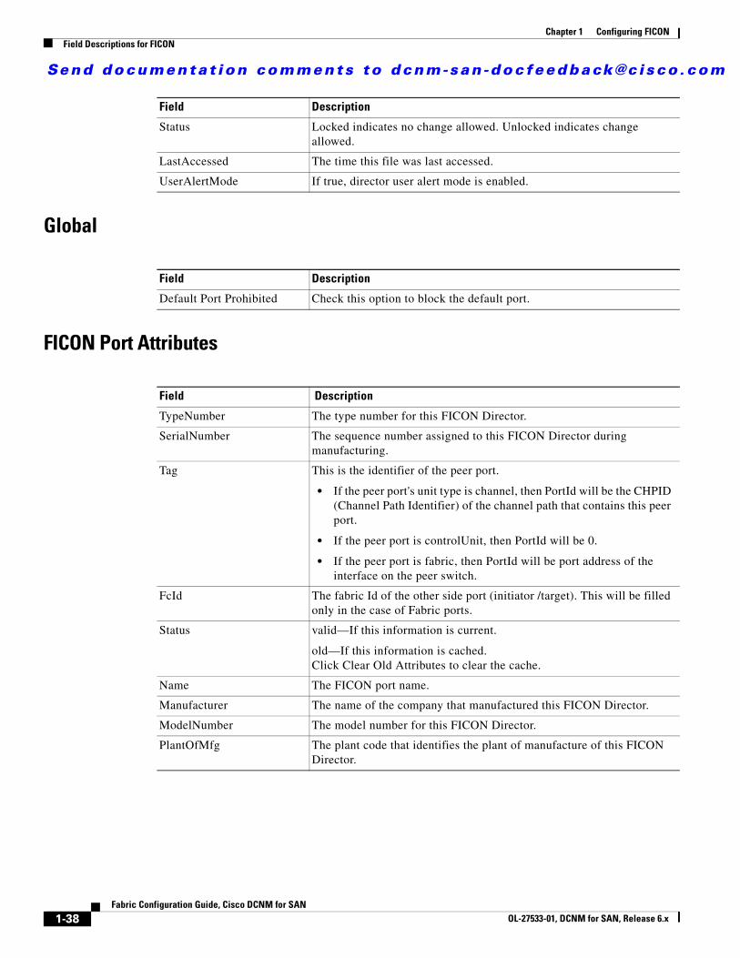
Send documenta t ion comments to dcnm-san -doc feedback@c i sco .com
1-38Fabric Configuration Guide, Cisco DCNM for SAN
OL-27533-01, DCNM for SAN, Release 6.x
Chapter 1 Configuring FICONField Descriptions for FICON
Global
FICON Port Attributes
Status Locked indicates no change allowed. Unlocked indicates change allowed.
LastAccessed The time this file was last accessed.
UserAlertMode If true, director user alert mode is enabled.
Field Description
Default Port Prohibited Check this option to block the default port.
Field Description
TypeNumber The type number for this FICON Director.
SerialNumber The sequence number assigned to this FICON Director during manufacturing.
Tag This is the identifier of the peer port.
• If the peer port's unit type is channel, then PortId will be the CHPID (Channel Path Identifier) of the channel path that contains this peer port.
• If the peer port is controlUnit, then PortId will be 0.
• If the peer port is fabric, then PortId will be port address of the interface on the peer switch.
FcId The fabric Id of the other side port (initiator /target). This will be filled only in the case of Fabric ports.
Status valid—If this information is current.
old—If this information is cached. Click Clear Old Attributes to clear the cache.
Name The FICON port name.
Manufacturer The name of the company that manufactured this FICON Director.
ModelNumber The model number for this FICON Director.
PlantOfMfg The plant code that identifies the plant of manufacture of this FICON Director.
Field Description
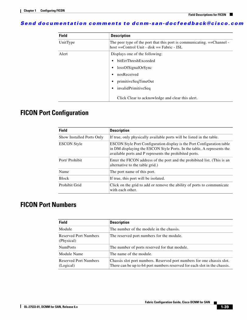
Send documenta t ion comments to dcnm-san -doc feedback@c i sco .com
1-39Fabric Configuration Guide, Cisco DCNM for SAN
OL-27533-01, DCNM for SAN, Release 6.x
Chapter 1 Configuring FICONField Descriptions for FICON
FICON Port Configuration
FICON Port Numbers
UnitType The peer type of the port that this port is communicating. ==Channel - host ==Control Unit - disk == Fabric - ISL
Alert Displays one of the following:
• bitErrThreshExceeded
• lossOfSignalOrSync
• nosReceived
• primitiveSeqTimeOut
• invalidPrimitiveSeq
Click Clear to acknowledge and clear this alert.
Field Description
Show Installed Ports Only If true, only physically available ports will be listed in the table.
ESCON Style ESCON Style Port Configuration display is the Port Configuration table in DM displaying the ESCON Style Ports. In the table, A represents the available ports and P represents the prohibited ports.
Port/ Prohibit Enter the FICON address of the port and the prohibited list. (This is an alternative to the table grid.)
Name The port name of this port.
Block If true, this port will be isolated.
Prohibit Grid Click on the grid to add or remove the ability of ports to communicate with each other.
Field Description
Module The number of the module in the chassis.
Reserved Port Numbers (Physical)
The reserved port numbers for the module.
NumPorts The number of ports reserved for that module.
Module Name The name of the module.
Reserved Port Numbers (Logical)
Chassis slot port numbers. Reserved port numbers for one chassis slot. There can be up to 64 port numbers reserved for each slot in the chassis.
Field Description
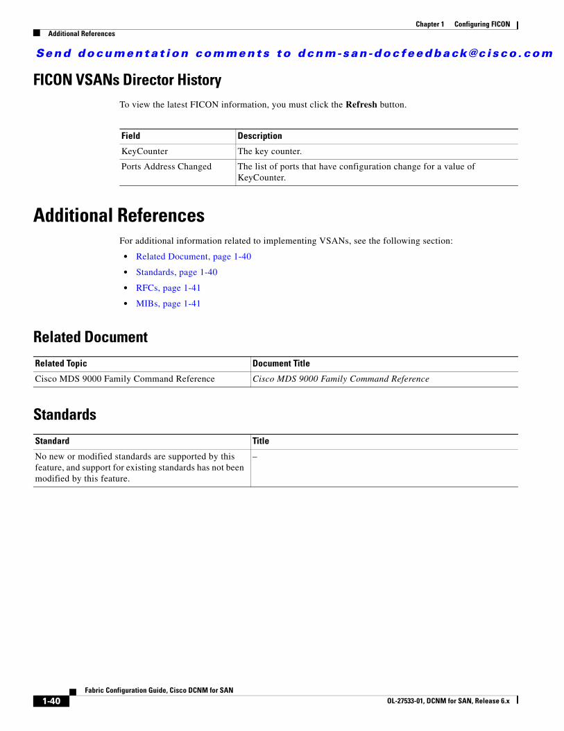
Send documenta t ion comments to dcnm-san -doc feedback@c i sco .com
1-40Fabric Configuration Guide, Cisco DCNM for SAN
OL-27533-01, DCNM for SAN, Release 6.x
Chapter 1 Configuring FICONAdditional References
FICON VSANs Director HistoryTo view the latest FICON information, you must click the Refresh button.
Additional ReferencesFor additional information related to implementing VSANs, see the following section:
• Related Document, page 1-40
• Standards, page 1-40
• RFCs, page 1-41
• MIBs, page 1-41
Related Document
Standards
Field Description
KeyCounter The key counter.
Ports Address Changed The list of ports that have configuration change for a value of KeyCounter.
Related Topic Document Title
Cisco MDS 9000 Family Command Reference Cisco MDS 9000 Family Command Reference
Standard Title
No new or modified standards are supported by this feature, and support for existing standards has not been modified by this feature.
–
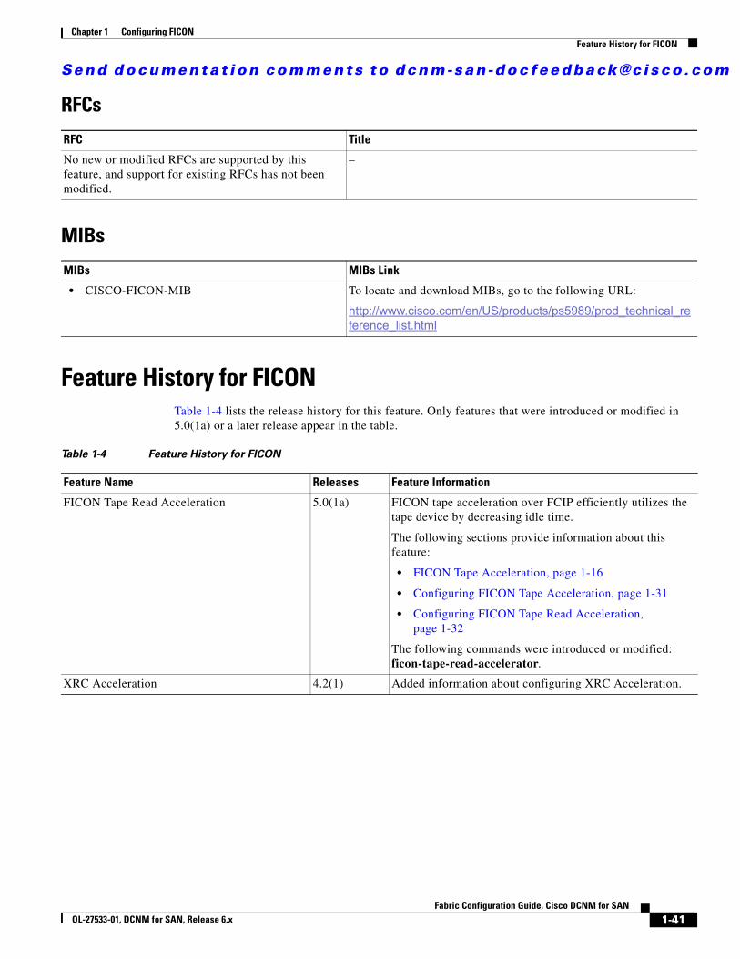
Send documenta t ion comments to dcnm-san -doc feedback@c i sco .com
1-41Fabric Configuration Guide, Cisco DCNM for SAN
OL-27533-01, DCNM for SAN, Release 6.x
Chapter 1 Configuring FICONFeature History for FICON
RFCs
MIBs
Feature History for FICONTable 1-4 lists the release history for this feature. Only features that were introduced or modified in 5.0(1a) or a later release appear in the table.
RFC Title
No new or modified RFCs are supported by this feature, and support for existing RFCs has not been modified.
–
MIBs MIBs Link
• CISCO-FICON-MIB To locate and download MIBs, go to the following URL:
http://www.cisco.com/en/US/products/ps5989/prod_technical_reference_list.html
Table 1-4 Feature History for FICON
Feature Name Releases Feature Information
FICON Tape Read Acceleration 5.0(1a) FICON tape acceleration over FCIP efficiently utilizes the tape device by decreasing idle time.
The following sections provide information about this feature:
• FICON Tape Acceleration, page 1-16
• Configuring FICON Tape Acceleration, page 1-31
• Configuring FICON Tape Read Acceleration, page 1-32
The following commands were introduced or modified: ficon-tape-read-accelerator.
XRC Acceleration 4.2(1) Added information about configuring XRC Acceleration.

Send documenta t ion comments to dcnm-san -doc feedback@c i sco .com
1-42Fabric Configuration Guide, Cisco DCNM for SAN
OL-27533-01, DCNM for SAN, Release 6.x
Chapter 1 Configuring FICONFeature History for FICON