cisco nexus 7000 series site preparation guide · iii cisco nexus 7000 series site preparation...
TRANSCRIPT

Cisco Nexus 7000 Series Site Preparation Guide For the Cisco Nexus 7004, 7009, 7010, and 7018 Switches
Created April 2008Last Updated July 14, 2014
Cisco Systems, Inc.www.cisco.com
Cisco has more than 200 offices worldwide. Addresses, phone numbers, and fax numbers are listed on the Cisco website at www.cisco.com/go/offices.

THE SPECIFICATIONS AND INFORMATION REGARDING THE PRODUCTS IN THIS MANUAL ARE SUBJECT TO CHANGE WITHOUT NOTICE. ALL STATEMENTS, INFORMATION, AND RECOMMENDATIONS IN THIS MANUAL ARE BELIEVED TO BE ACCURATE BUT ARE PRESENTED WITHOUT WARRANTY OF ANY KIND, EXPRESS OR IMPLIED. USERS MUST TAKE FULL RESPONSIBILITY FOR THEIR APPLICATION OF ANY PRODUCTS.
THE SOFTWARE LICENSE AND LIMITED WARRANTY FOR THE ACCOMPANYING PRODUCT ARE SET FORTH IN THE INFORMATION PACKET THAT SHIPPED WITH THE PRODUCT AND ARE INCORPORATED HEREIN BY THIS REFERENCE. IF YOU ARE UNABLE TO LOCATE THE SOFTWARE LICENSE OR LIMITED WARRANTY, CONTACT YOUR CISCO REPRESENTATIVE FOR A COPY.
The following information is for FCC compliance of Class A devices: This equipment has been tested and found to comply with the limits for a Class A digital device, pursuant to part 15 of the FCC rules. These limits are designed to provide reasonable protection against harmful interference when the equipment is operated in a commercial environment. This equipment generates, uses, and can radiate radio-frequency energy and, if not installed and used in accordance with the instruction manual, may cause harmful interference to radio communications. Operation of this equipment in a residential area is likely to cause harmful interference, in which case users will be required to correct the interference at their own expense.
The following information is for FCC compliance of Class B devices: This equipment has been tested and found to comply with the limits for a Class B digital device, pursuant to part 15 of the FCC rules. These limits are designed to provide reasonable protection against harmful interference in a residential installation. This equipment generates, uses and can radiate radio frequency energy and, if not installed and used in accordance with the instructions, may cause harmful interference to radio communications. However, there is no guarantee that interference will not occur in a particular installation. If the equipment causes interference to radio or television reception, which can be determined by turning the equipment off and on, users are encouraged to try to correct the interference by using one or more of the following measures:
• Reorient or relocate the receiving antenna.
• Increase the separation between the equipment and receiver.
• Connect the equipment into an outlet on a circuit different from that to which the receiver is connected.
• Consult the dealer or an experienced radio/TV technician for help.
Modifications to this product not authorized by Cisco could void the FCC approval and negate your authority to operate the product.
The Cisco implementation of TCP header compression is an adaptation of a program developed by the University of California, Berkeley (UCB) as part of UCB’s public domain version of the UNIX operating system. All rights reserved. Copyright © 1981, Regents of the University of California.
NOTWITHSTANDING ANY OTHER WARRANTY HEREIN, ALL DOCUMENT FILES AND SOFTWARE OF THESE SUPPLIERS ARE PROVIDED “AS IS” WITH ALL FAULTS. CISCO AND THE ABOVE-NAMED SUPPLIERS DISCLAIM ALL WARRANTIES, EXPRESSED OR IMPLIED, INCLUDING, WITHOUT LIMITATION, THOSE OF MERCHANTABILITY, FITNESS FOR A PARTICULAR PURPOSE AND NONINFRINGEMENT OR ARISING FROM A COURSE OF DEALING, USAGE, OR TRADE PRACTICE.
IN NO EVENT SHALL CISCO OR ITS SUPPLIERS BE LIABLE FOR ANY INDIRECT, SPECIAL, CONSEQUENTIAL, OR INCIDENTAL DAMAGES, INCLUDING, WITHOUT LIMITATION, LOST PROFITS OR LOSS OR DAMAGE TO DATA ARISING OUT OF THE USE OR INABILITY TO USE THIS MANUAL, EVEN IF CISCO OR ITS SUPPLIERS HAVE BEEN ADVISED OF THE POSSIBILITY OF SUCH DAMAGES.
Cisco and the Cisco logo are trademarks or registered trademarks of Cisco and/or its affiliates in the U.S. and other countries. To view a list of Cisco trademarks, go to this URL: www.cisco.com/go/trademarks. Third-party trademarks mentioned are the property of their respective owners. The use of the word partner does not imply a partnership relationship between Cisco and any other company. (1721R)
Any Internet Protocol (IP) addresses and phone numbers used in this document are not intended to be actual addresses and phone numbers. Any examples, command display output, network topology diagrams, and other figures included in the document are shown for illustrative purposes only. Any use of actual IP addresses or phone numbers in illustrative content is unintentional and coincidental.
© 2008-2014 Cisco Systems, Inc. All rights reserved.
C O N T E N T S
New and Changed Information v
Preface vii
Audience vii
Document Organization vii
Document Conventions vii
Related Documentation xiv
Hardware Documents xiv
Software Documents xiv
Documentation Feedback xiv
Obtaining Documentation and Submitting a Service Request xiv
C H A P T E R 1 Overview 1-1
C H A P T E R 2 Preparing the Site 2-1
Information About the Site Requirements 2-1
Temperature 2-2
Humidity 2-3
Altitude 2-3
Dust and Particles 2-3
Corrosion 2-3
Electromagnetic and Radio Frequency Interference 2-4
Shock and Vibration 2-4
Grounding 2-4
Power Source 2-5
A P P E N D I X A Cabinet and Rack Requirements A-1
General Requirements for Cabinets and Racks A-1
Cabinet and Rack Vendors A-4
C H A P T E R B Technical Specifications B-1
Environmental Specifications for Cisco Nexus 7000 Series Switches B-1
iiiCisco Nexus 7000 Series Site Preparation Guide
Contents
Physical Specifications for the Cisco Nexus 7000 Series Chassis B-2
Power Specifications for Cisco Nexus 7000 Series Switches B-8
Power Requirements for Switch Components B-8
Power Supply Configuration Modes B-12
Power Supply Cable Specifications B-16
Chassis Clearances B-22
Cisco Nexus 7004 Chassis Clearances B-22
Cisco Nexus 7009 Chassis Clearances B-27
Cisco Nexus 7010 Chassis Clearances B-33
Cisco Nexus 7018 Chassis Clearances B-35
Facility Cooling Requirements B-37
Chassis Airflow B-38
A P P E N D I X C Site Preparation and Maintenance Records C-1
Site Preparation Checklist C-1
Contact and Site Information C-3
Chassis and Module Information C-3
ivCisco Nexus 7000 Series Site Preparation Guide
vCisco Nexus 7000 Series Site Preparation Guide
New and Changed Information
This chapter provides release-specific information for each new and changed feature in the Cisco Nexus 7000 Series Site Preparation Guide. The latest version of this document is available at the following Cisco website:
http://www.cisco.com/en/US/docs/switches/datacenter/hw/nexus7000/site_prep/guide/nexus7k_siteprep_book.html
Table 1 summarizes the new and changed features for the Cisco Nexus 7000 Series Site Preparation Guide, and tells you where they are documented.
Table 1 New and Changed Features for Release 6.2(10)
Feature DescriptionChanged in Release Where Documented
6-port 100-Gigabit Ethernet CPAK I/O module
New I/O module (N7K-F306CK-25) 6.2(10) Chapter 1, “Overview”
Appendix B, “Technical Specifications”
viCisco Nexus 7000 Series Site Preparation Guide
New and Changed Information
Preface
This preface describes the audience, organization, and conventions of the Cisco Nexus 7000 Series Site Preparation Guide. It also provides information on how to obtain related documentation.
AudienceThis guide is intended for anyone who plans the facilities, including space, floor weighting, power, cooling, cabling, delivery, and storage for the installation of the Cisco Nexus 7000 Series switches.
Document OrganizationThis document is organized into the following chapters:
Document ConventionsThis document uses the following conventions for notes, cautions, and safety warnings.
Notes and Cautions contain important information that you should be aware of.
Chapter Description
Chapter 1, “Overview” Provides an overview of the Cisco Nexus 7000 Series switches.
Chapter 2, “Preparing the Site” Describes the basic site requirements for installing the Cisco Nexus 7000 Series switches.
Chapter A, “Cabinet and Rack Requirements” Describes the cabinet and rack requirements for the Cisco Nexus 7000 Series switches.
Chapter B, “Technical Specifications” Describes the technical specifications for the Cisco Nexus 7000 Series switches.
Chapter C, “Site Preparation and Maintenance Records”
Provides a site planning list to prepare your site for the Cisco Nexus 7000 Series switches.
viiCisco Nexus 7000 Series Site Preparation Guide
Note Means reader take note. Notes contain helpful suggestions or references to material that are not covered in the publication.
Caution Means reader be careful. You are capable of doing something that might result in equipment damage or loss of data.
Safety warnings appear throughout this publication in procedures that, if performed incorrectly, can cause physical injuries. A warning symbol precedes each warning statement.
Warning IMPORTANT SAFETY INSTRUCTIONS
This warning symbol means danger. You are in a situation that could cause bodily injury. Before you work on any equipment, be aware of the hazards involved with electrical circuitry and be familiar with standard practices for preventing accidents. Use the statement number provided at the end of each warning to locate its translation in the translated safety warnings that accompanied this device. Statement 1071
SAVE THESE INSTRUCTIONS
Waarschuwing BELANGRIJKE VEILIGHEIDSINSTRUCTIES
Dit waarschuwingssymbool betekent gevaar. U verkeert in een situatie die lichamelijk letsel kan veroorzaken. Voordat u aan enige apparatuur gaat werken, dient u zich bewust te zijn van de bij elektrische schakelingen betrokken risico's en dient u op de hoogte te zijn van de standaard praktijken om ongelukken te voorkomen. Gebruik het nummer van de verklaring onderaan de waarschuwing als u een vertaling van de waarschuwing die bij het apparaat wordt geleverd, wilt raadplegen.
BEWAAR DEZE INSTRUCTIES
Varoitus TÄRKEITÄ TURVALLISUUSOHJEITA
Tämä varoitusmerkki merkitsee vaaraa. Tilanne voi aiheuttaa ruumiillisia vammoja. Ennen kuin käsittelet laitteistoa, huomioi sähköpiirien käsittelemiseen liittyvät riskit ja tutustu onnettomuuksien yleisiin ehkäisytapoihin. Turvallisuusvaroitusten käännökset löytyvät laitteen mukana toimitettujen käännettyjen turvallisuusvaroitusten joukosta varoitusten lopussa näkyvien lausuntonumeroiden avulla.
SÄILYTÄ NÄMÄ OHJEET
viiiCisco Nexus 7000 Series Site Preparation Guide
Attention IMPORTANTES INFORMATIONS DE SÉCURITÉ
Ce symbole d'avertissement indique un danger. Vous vous trouvez dans une situation pouvant entraîner des blessures ou des dommages corporels. Avant de travailler sur un équipement, soyez conscient des dangers liés aux circuits électriques et familiarisez-vous avec les procédures couramment utilisées pour éviter les accidents. Pour prendre connaissance des traductions des avertissements figurant dans les consignes de sécurité traduites qui accompagnent cet appareil, référez-vous au numéro de l'instruction situé à la fin de chaque avertissement.
CONSERVEZ CES INFORMATIONS
Warnung WICHTIGE SICHERHEITSHINWEISE
Dieses Warnsymbol bedeutet Gefahr. Sie befinden sich in einer Situation, die zu Verletzungen führen kann. Machen Sie sich vor der Arbeit mit Geräten mit den Gefahren elektrischer Schaltungen und den üblichen Verfahren zur Vorbeugung vor Unfällen vertraut. Suchen Sie mit der am Ende jeder Warnung angegebenen Anweisungsnummer nach der jeweiligen Übersetzung in den übersetzten Sicherheitshinweisen, die zusammen mit diesem Gerät ausgeliefert wurden.
BEWAHREN SIE DIESE HINWEISE GUT AUF.
Avvertenza IMPORTANTI ISTRUZIONI SULLA SICUREZZA
Questo simbolo di avvertenza indica un pericolo. La situazione potrebbe causare infortuni alle persone. Prima di intervenire su qualsiasi apparecchiatura, occorre essere al corrente dei pericoli relativi ai circuiti elettrici e conoscere le procedure standard per la prevenzione di incidenti. Utilizzare il numero di istruzione presente alla fine di ciascuna avvertenza per individuare le traduzioni delle avvertenze riportate in questo documento.
CONSERVARE QUESTE ISTRUZIONI
Advarsel VIKTIGE SIKKERHETSINSTRUKSJONER
Dette advarselssymbolet betyr fare. Du er i en situasjon som kan føre til skade på person. Før du begynner å arbeide med noe av utstyret, må du være oppmerksom på farene forbundet med elektriske kretser, og kjenne til standardprosedyrer for å forhindre ulykker. Bruk nummeret i slutten av hver advarsel for å finne oversettelsen i de oversatte sikkerhetsadvarslene som fulgte med denne enheten.
TA VARE PÅ DISSE INSTRUKSJONENE
Aviso INSTRUÇÕES IMPORTANTES DE SEGURANÇA
Este símbolo de aviso significa perigo. Você está em uma situação que poderá ser causadora de lesões corporais. Antes de iniciar a utilização de qualquer equipamento, tenha conhecimento dos perigos envolvidos no manuseio de circuitos elétricos e familiarize-se com as práticas habituais de prevenção de acidentes. Utilize o número da instrução fornecido ao final de cada aviso para localizar sua tradução nos avisos de segurança traduzidos que acompanham este dispositivo.
GUARDE ESTAS INSTRUÇÕES
ixCisco Nexus 7000 Series Site Preparation Guide
¡Advertencia! INSTRUCCIONES IMPORTANTES DE SEGURIDAD
Este símbolo de aviso indica peligro. Existe riesgo para su integridad física. Antes de manipular cualquier equipo, considere los riesgos de la corriente eléctrica y familiarícese con los procedimientos estándar de prevención de accidentes. Al final de cada advertencia encontrará el número que le ayudará a encontrar el texto traducido en el apartado de traducciones que acompaña a este dispositivo.
GUARDE ESTAS INSTRUCCIONES
Varning! VIKTIGA SÄKERHETSANVISNINGAR
Denna varningssignal signalerar fara. Du befinner dig i en situation som kan leda till personskada. Innan du utför arbete på någon utrustning måste du vara medveten om farorna med elkretsar och känna till vanliga förfaranden för att förebygga olyckor. Använd det nummer som finns i slutet av varje varning för att hitta dess översättning i de översatta säkerhetsvarningar som medföljer denna anordning.
SPARA DESSA ANVISNINGAR
xCisco Nexus 7000 Series Site Preparation Guide
Aviso INSTRUÇÕES IMPORTANTES DE SEGURANÇA
Este símbolo de aviso significa perigo. Você se encontra em uma situação em que há risco de lesões corporais. Antes de trabalhar com qualquer equipamento, esteja ciente dos riscos que envolvem os circuitos elétricos e familiarize-se com as práticas padrão de prevenção de acidentes. Use o número da declaração fornecido ao final de cada aviso para localizar sua tradução nos avisos de segurança traduzidos que acompanham o dispositivo.
GUARDE ESTAS INSTRUÇÕES
Advarsel VIGTIGE SIKKERHEDSANVISNINGER
Dette advarselssymbol betyder fare. Du befinder dig i en situation med risiko for legemesbeskadigelse. Før du begynder arbejde på udstyr, skal du være opmærksom på de involverede risici, der er ved elektriske kredsløb, og du skal sætte dig ind i standardprocedurer til undgåelse af ulykker. Brug erklæringsnummeret efter hver advarsel for at finde oversættelsen i de oversatte advarsler, der fulgte med denne enhed.
GEM DISSE ANVISNINGER
xiCisco Nexus 7000 Series Site Preparation Guide
xiiCisco Nexus 7000 Series Site Preparation Guide
xiiiCisco Nexus 7000 Series Site Preparation Guide

Related DocumentationCisco Nexus 7000 Series documentation includes the following documents:
Hardware DocumentsCisco Nexus 7000 Series Site Preparation Guide
Cisco Nexus 7000 Series Hardware Installation and Reference Guide
Cisco Nexus 7000 Series Regulatory Compliance and Safety Information
Cisco Nexus 7000 Series Connectivity Management Processor Configuration Guide
Software DocumentsThe Cisco Nexus 7000 Series switches ship with the Cisco NX-OS software. You can find software documentation for the Cisco NX-OS software at the following URL:
http://www.cisco.com/en/US/products/ps9402/tsd_products_support_series_home.html
The Cisco Data Center Network Manager (DCNM) supports the Cisco Nexus 7000 Series. You can find documentation for DCNM at the following URL:
http://www.cisco.com/en/US/products/ps9369/tsd_products_support_series_home.html
Documentation FeedbackTo provide technical feedback on this document, or to report an error or omission, please send your comments to [email protected]. We appreciate your feedback.
Obtaining Documentation and Submitting a Service RequestFor information on obtaining documentation, submitting a service request, and gathering additional information, see the monthly What’s New in Cisco Product Documentation, which also lists all new and revised Cisco technical documentation, at:
http://www.cisco.com/en/US/docs/general/whatsnew/whatsnew.html
Subscribe to the What’s New in Cisco Product Documentation as a Really Simple Syndication (RSS) feed and set content to be delivered directly to your desktop using a reader application. The RSS feeds are a free service and Cisco currently supports RSS version 2.0.
xivCisco Nexus 7000 Series Site Preparation Guide
C H A P T E R 1
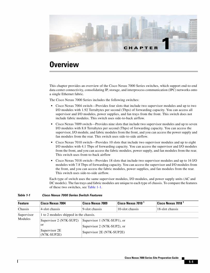
OverviewThis chapter provides an overview of the Cisco Nexus 7000 Series switches, which support end-to-end data center connectivity, consolidating IP, storage, and interprocess communication (IPC) networks onto a single Ethernet fabric.
The Cisco Nexus 7000 Series includes the following switches:
• Cisco Nexus 7004 switch—Provides four slots that include two supervisor modules and up to two I/O modules with 1.92 Terrabytes per second (Tbps) of forwarding capacity. You can access all supervisor and I/O modules, power supplies, and fan trays from the front. This switch does not include fabric modules. This switch uses side-to-back airflow.
• Cisco Nexus 7009 switch—Provides nine slots that include two supervisor modules and up to seven I/O modules with 8.8 Terrabytes per second (Tbps) of forwarding capacity. You can access the supervisor, I/O module, and fabric modules from the front, and you can access the power supply and fan modules from the rear. This switch uses side-to-side airflow.
• Cisco Nexus 7010 switch—Provides 10 slots that include two supervisor modules and up to eight I/O modules with 4.1 Tbps of forwarding capacity. You can access the supervisor and I/O modules from the front, and you can access the fabric modules, power supply, and fan modules from the rear. This switch uses front-to-back airflow
• Cisco Nexus 7018 switch—Provides 18 slots that include two supervisor modules and up to 16 I/O modules with 7.8 Tbps of forwarding capacity. You can access the supervisor and I/O modules from the front, and you can access the fabric modules, power supplies, and fan modules from the rear. This switch uses side-to-side airflow.
Each type of switch uses the same supervisor modules, I/O modules, and power supply units (AC and DC models). The fan trays and fabric modules are unique to each type of chassis. To compare the features of these two switches, see Table 1-1.
Table 1-1 Cisco Nexus 7000 Series Switch Features
Feature Cisco Nexus 7004 Cisco Nexus 7009 Cisco Nexus 7010 1 Cisco Nexus 7018 1
Chassis 4-slot chassis 9-slot chassis 10-slot chassis 18-slot chassis
Supervisor Modules
1 to 2 modules shipped in the chassis.
Supervisor 2 (N7K-SUP2) or
Supervisor 2E (N7K-SUP2E)
Supervisor 1 (N7K-SUP1), or
Supervisor 2 (N7K-SUP2), or
Supervisor 2E (N7K-SUP2E)
1-1Cisco Nexus 7000 Series Site Preparation Guide
Chapter 1 Overview
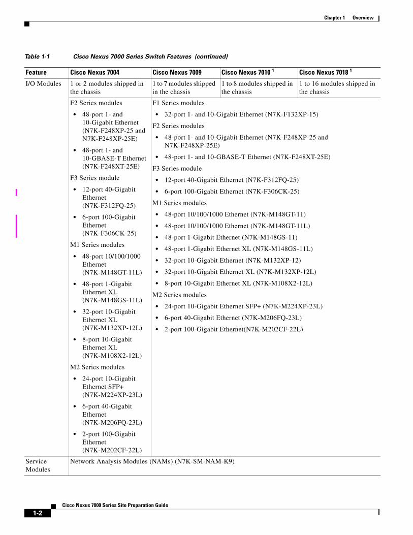
I/O Modules 1 or 2 modules shipped in the chassis
1 to 7 modules shipped in the chassis
1 to 8 modules shipped in the chassis
1 to 16 modules shipped in the chassis
F2 Series modules
• 48-port 1- and 10-Gigabit Ethernet (N7K-F248XP-25 and N7K-F248XP-25E)
• 48-port 1- and 10-GBASE-T Ethernet (N7K-F248XT-25E)
F3 Series module
• 12-port 40-Gigabit Ethernet (N7K-F312FQ-25)
• 6-port 100-Gigabit Ethernet (N7K-F306CK-25)
M1 Series modules
• 48-port 10/100/1000 Ethernet (N7K-M148GT-11L)
• 48-port 1-Gigabit Ethernet XL (N7K-M148GS-11L)
• 32-port 10-Gigabit Ethernet XL (N7K-M132XP-12L)
• 8-port 10-Gigabit Ethernet XL (N7K-M108X2-12L)
M2 Series modules
• 24-port 10-Gigabit Ethernet SFP+ (N7K-M224XP-23L)
• 6-port 40-Gigabit Ethernet (N7K-M206FQ-23L)
• 2-port 100-Gigabit Ethernet (N7K-M202CF-22L)
F1 Series modules
• 32-port 1- and 10-Gigabit Ethernet (N7K-F132XP-15)
F2 Series modules
• 48-port 1- and 10-Gigabit Ethernet (N7K-F248XP-25 and N7K-F248XP-25E)
• 48-port 1- and 10-GBASE-T Ethernet (N7K-F248XT-25E)
F3 Series module
• 12-port 40-Gigabit Ethernet (N7K-F312FQ-25)
• 6-port 100-Gigabit Ethernet (N7K-F306CK-25)
M1 Series modules
• 48-port 10/100/1000 Ethernet (N7K-M148GT-11)
• 48-port 10/100/1000 Ethernet (N7K-M148GT-11L)
• 48-port 1-Gigabit Ethernet (N7K-M148GS-11)
• 48-port 1-Gigabit Ethernet XL (N7K-M148GS-11L)
• 32-port 10-Gigabit Ethernet (N7K-M132XP-12)
• 32-port 10-Gigabit Ethernet XL (N7K-M132XP-12L)
• 8-port 10-Gigabit Ethernet XL (N7K-M108X2-12L)
M2 Series modules
• 24-port 10-Gigabit Ethernet SFP+ (N7K-M224XP-23L)
• 6-port 40-Gigabit Ethernet (N7K-M206FQ-23L)
• 2-port 100-Gigabit Ethernet(N7K-M202CF-22L)
Service Modules
Network Analysis Modules (NAMs) (N7K-SM-NAM-K9)
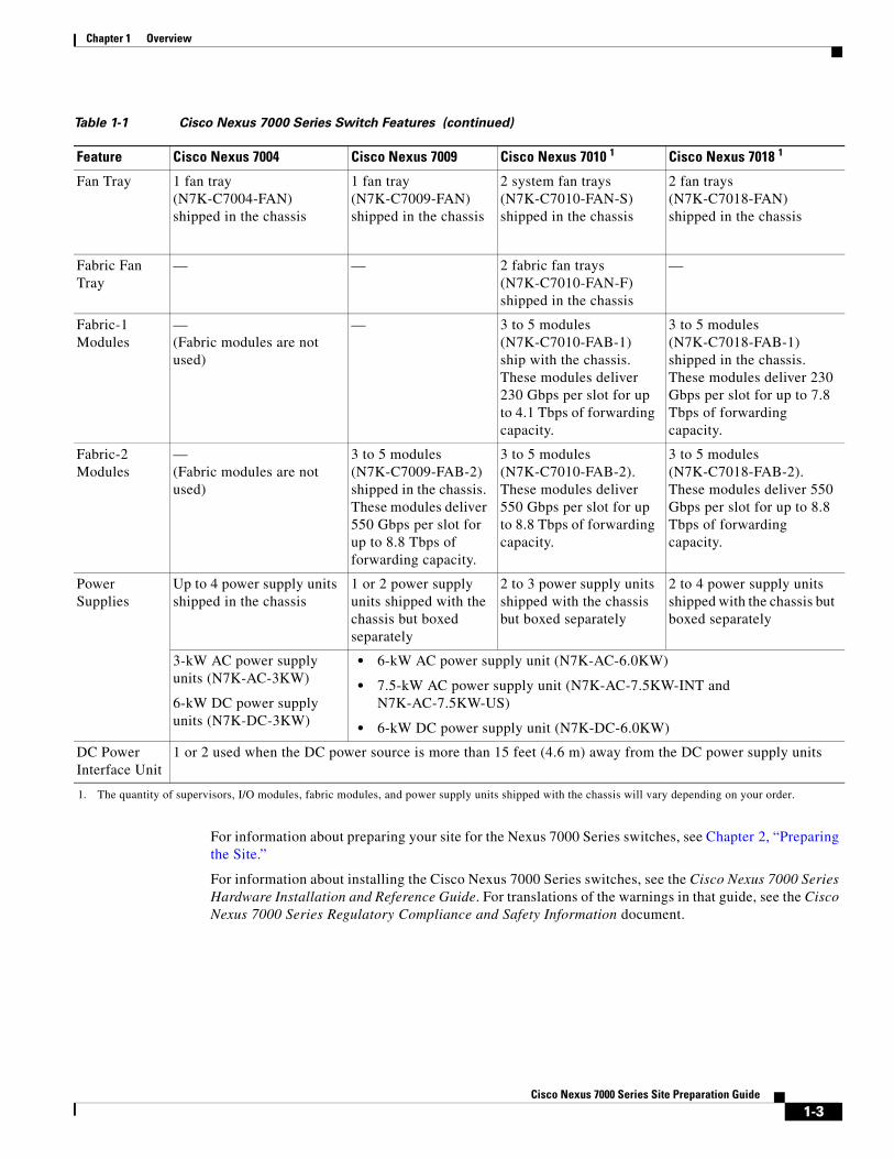
Table 1-1 Cisco Nexus 7000 Series Switch Features (continued)
Feature Cisco Nexus 7004 Cisco Nexus 7009 Cisco Nexus 7010 1 Cisco Nexus 7018 1
1-2Cisco Nexus 7000 Series Site Preparation Guide
Chapter 1 Overview
For information about preparing your site for the Nexus 7000 Series switches, see Chapter 2, “Preparing the Site.”
For information about installing the Cisco Nexus 7000 Series switches, see the Cisco Nexus 7000 Series Hardware Installation and Reference Guide. For translations of the warnings in that guide, see the Cisco Nexus 7000 Series Regulatory Compliance and Safety Information document.
Fan Tray 1 fan tray(N7K-C7004-FAN)shipped in the chassis
1 fan tray (N7K-C7009-FAN) shipped in the chassis
2 system fan trays (N7K-C7010-FAN-S) shipped in the chassis
2 fan trays (N7K-C7018-FAN) shipped in the chassis
Fabric Fan Tray
— — 2 fabric fan trays (N7K-C7010-FAN-F) shipped in the chassis
—
Fabric-1 Modules
— (Fabric modules are not used)
— 3 to 5 modules (N7K-C7010-FAB-1) ship with the chassis. These modules deliver 230 Gbps per slot for up to 4.1 Tbps of forwarding capacity.
3 to 5 modules (N7K-C7018-FAB-1) shipped in the chassis. These modules deliver 230 Gbps per slot for up to 7.8 Tbps of forwarding capacity.
Fabric-2 Modules
— (Fabric modules are not used)
3 to 5 modules (N7K-C7009-FAB-2) shipped in the chassis. These modules deliver 550 Gbps per slot for up to 8.8 Tbps of forwarding capacity.
3 to 5 modules (N7K-C7010-FAB-2). These modules deliver 550 Gbps per slot for up to 8.8 Tbps of forwarding capacity.
3 to 5 modules (N7K-C7018-FAB-2). These modules deliver 550 Gbps per slot for up to 8.8 Tbps of forwarding capacity.
Power Supplies
Up to 4 power supply units shipped in the chassis
1 or 2 power supply units shipped with the chassis but boxed separately
2 to 3 power supply units shipped with the chassis but boxed separately
2 to 4 power supply units shipped with the chassis but boxed separately
3-kW AC power supply units (N7K-AC-3KW)
6-kW DC power supply units (N7K-DC-3KW)
• 6-kW AC power supply unit (N7K-AC-6.0KW)
• 7.5-kW AC power supply unit (N7K-AC-7.5KW-INT and N7K-AC-7.5KW-US)
• 6-kW DC power supply unit (N7K-DC-6.0KW)
DC Power Interface Unit
1 or 2 used when the DC power source is more than 15 feet (4.6 m) away from the DC power supply units
1. The quantity of supervisors, I/O modules, fabric modules, and power supply units shipped with the chassis will vary depending on your order.
Table 1-1 Cisco Nexus 7000 Series Switch Features (continued)
Feature Cisco Nexus 7004 Cisco Nexus 7009 Cisco Nexus 7010 1 Cisco Nexus 7018 1
1-3Cisco Nexus 7000 Series Site Preparation Guide

Chapter 1 Overview
1-4Cisco Nexus 7000 Series Site Preparation Guide
C H A P T E R 2
Preparing the SiteThis chapter describes the basic site requirements that you should be aware of as you prepare to install your Cisco Nexus 7000 Series switches.
This chapter includes the following sections:
• Information About the Site Requirements, page 2-1
• Temperature, page 2-2
• Humidity, page 2-3
• Altitude, page 2-3
• Dust and Particles, page 2-3
• Corrosion, page 2-3
• Electromagnetic and Radio Frequency Interference, page 2-4
• Shock and Vibration, page 2-4
• Grounding, page 2-4
• Power Source, page 2-5
Information About the Site RequirementsEnvironmental factors can adversely affect the performance and life span of your switch. The Cisco Nexus 7000 Series switches require a dry, clean, well-ventilated, and air-conditioned environment. To ensure normal operation, you must maintain ambient airflow. If the airflow is blocked or restricted, or if the intake air is too warm, an overtemperature condition can occur and the environmental monitor on the switch will shut down to protect the switch components.
In a 42-rack unit (RU) rack, you can maximize the number of Cisco Nexus 7000 Series switch models as follows:
• Six Cisco Nexus 7004 chassis
• Three Cisco Nexus 7009 chassis
• Two Cisco Nexus 7010 chassis
• One Cisco Nexus 7018 chassis
You must also allow enough room in front for loading the chassis using a mechanical lift and enough room in the rear for removing the switch components (this requirement in the rear applies only to the Cisco Nexus 7009, 7010, and 7018 chassis). When mounting the Cisco Nexus 7000 Series chassis in a
2-1Cisco Nexus 7000 Series Site Preparation Guide
Chapter 2 Preparing the SiteTemperature
rack with other equipment, ensure that the exhaust from the other equipment does not blow into the air intake vent of the Cisco Nexus 7000 Series chassis. If your site has hot and cold aisles, align the rack or cabinet air intake to a cold aisle and exhaust to a hot aisle.
TemperatureTemperature extremes can cause the Cisco Nexus 7000 Series switches to operate at reduced efficiency and cause a variety of problems, including premature aging, failure of chips, and failure of switches. In addition, extreme temperature fluctuations can cause chips to become loose in their sockets. The Cisco Nexus 7000 Series switches should operate in an environment that is not colder than 32°F (0°C) or hotter than 104°F (40°C).
To control the switch temperature, you must make sure that the switch has adequate airflow, as follows:
• The Cisco Nexus 7004 switch requires side-to-back airflow, which requires that you leave at least 11 inches (27.9 cm) free on the right side of the chassis (as seen from the front side of the chassis, which shows all of the chassis modules). You must be sure that the cables do not block the airflow into the chassis on the right side (for more information, see the “Chassis Clearances” section on page B-22).
• The Cisco Nexus 7009 switch requires side-to-side airflow, which requires that you leave at least 11 inches (27.9 cm) free on both sides of the chassis (or 22 inches [55.8 cm] between two Cisco Nexus 7009 or 7018 switches]), and you must be sure that cables do not block the airflow from the lower right front of the chassis (for more information, see the “Chassis Clearances” section on page B-22).
• The Cisco Nexus 7010 switch requires front-to-back airflow, which requires that you do not block the front air intake or the rear exhaust areas (for more information, see the “Chassis Clearances” section on page B-22).
• The Cisco Nexus 7018 switch requires side-to-side airflow, which requires that you leave at least 11 inches (27.9 cm) free on both sides of the chassis (or 22 inches [55.8 cm] between two Cisco Nexus 7009 or 7018 switches]), and you must be sure that cables do not block the airflow from the lower right front of the chassis (for more information, see the “Chassis Clearances” section on page B-22).
To prevent overheating and to minimize the energy spent to cool the Cisco Nexus 7000 Series switch, do not place the chassis next to a heat source of any kind, including heating vents during cold weather.
Adequate ventilation is particularly important if you are operating a Cisco Nexus 7000 Series switch at high altitudes. Make sure that all slots and openings on the chassis remain unobstructed, especially the fan vents. Clean the installation site at regular intervals to avoid buildup of dust and debris, which can cause a switch to overheat.
If the Cisco Nexus 7000 Series switch is exposed to abnormally cold temperatures, allow a 2-hour warm-up period to bring it up to a normal operating temperature before you turn the switch on.
Caution If you do not allow a 2-hour warm-up period when temperatures are abnormally cold, you can damage the internal components.
Note The Cisco Nexus 7000 Series switches are equipped with internal air temperature sensors that trigger a minor alarm at 104°F (40°C) and a major alarm at 131°F (55°C).
2-2Cisco Nexus 7000 Series Site Preparation Guide
Chapter 2 Preparing the SiteHumidity
HumidityHigh humidity can cause moisture to seep into the Cisco Nexus 7000 Series switches. Moisture can cause corrosion of internal components and degradation of properties such as electrical resistance, thermal conductivity, physical strength, and size. The Cisco Nexus 7000 Series is rated to operate at 8 to 80 percent relative humidity, with a humidity gradation of 10 percent per hour.
The Cisco Nexus 7000 Series switches can withstand from 5 to 90 percent relative humidity. Buildings in which the climate is controlled by air-conditioning in the warmer months and by heat during the colder months usually maintain an acceptable level of humidity for the switch equipment. However, if a Cisco Nexus 7000 Series switch is located in an unusually humid location, you should use a dehumidifier to maintain the humidity within an acceptable range.
AltitudeIf you operate a Cisco Nexus 7000 Series switch at a high altitude (low pressure), the efficiency of forced and convection cooling is reduced and can result in electrical problems that are related to arcing and corona effects. This condition can also cause sealed components with internal pressure, such as electrolytic capacitors, to fail or to perform at a reduced efficiency. The Cisco Nexus 7000 Series is rated to operate at altitudes from –500 to 13,123 feet (–152 to 4,000 meters). You can store the switch at altitudes of –1,000 to 30,000 feet (–305 to 9,144 meters).
Dust and ParticlesExhaust fans cool power supplies and system fan trays cool switches by drawing in air and exhausting air out through various openings in the chassis. However, fans also ingest dust and other particles, causing contaminant buildup in the switch and increased internal chassis temperature. A clean operating environment can greatly reduce the negative effects of dust and other particles, which act as insulators and interfere with the mechanical components in the switch.
Note In the Cisco Nexus 7004 and 7010 switches, you can install an optional air filter in a nonclean environment.
In addition to regular cleaning, follow these precautions to avoid contamination of your equipment:
• Do not permit smoking near the Cisco Nexus 7000 Series switch.
• Do not permit food or drink near the Cisco Nexus 7000 Series switch.
CorrosionThe corrosion of switch connectors is a gradual process that can eventually lead to intermittent failures of electrical circuits. The oil from your fingers or prolonged exposure to high temperature or humidity can corrode the gold-plated edge connectors and pin connectors on various components in the Cisco Nexus 7000 Series switches. To prevent corrosion, avoid touching contacts on modules and protect the switch from extreme temperatures and moist, salty environments.
2-3Cisco Nexus 7000 Series Site Preparation Guide
Chapter 2 Preparing the SiteElectromagnetic and Radio Frequency Interference
Electromagnetic and Radio Frequency InterferenceElectromagnetic interference (EMI) and radio frequency interference (RFI) from the Cisco Nexus 7000 Series switch can adversely affect switches such as radio and television (TV) receivers operating near the switch. Radio frequencies that emanate from the Cisco Nexus 7000 Series switch can also interfere with cordless and low-power telephones. Conversely, RFI from high-power telephones can cause spurious characters to appear on the switch monitor.
RFI is defined as any EMI with a frequency above 10 kHz. This type of interference can travel from the switch to other devices through the power cable and power source or through the air like transmitted radio waves. The Federal Communications Commission (FCC) publishes specific regulations to limit the amount of EMI and RFI that can be emitted by computing equipment. Each Cisco Nexus 7000 Series switch meets these FCC regulations.
To reduce the possibility of EMI and RFI, follow these guidelines:
• Cover all open expansion slots with a metal filler.
• Always use shielded cables with metal connector shells for attaching peripherals to the switch.
When wires are run for any significant distance in an electromagnetic field, interference can occur between the field and the signals on the wires and cause the following implications:
• Bad wiring can result in radio interference emanating from the plant wiring.
• Strong EMI, especially when it is caused by lightning or radio transmitters, can destroy the signal drivers and receivers in the chassis and even create an electrical hazard by conducting power surges through lines into equipment.
Note To predict and prevent strong EMI, you might need to consult experts in radio frequency interference (RFI).
The wiring is unlikely to emit radio interference if you use twisted-pair cable with a good distribution of grounding conductors. If you exceed the recommended distances, use a high-quality twisted-pair cable with one ground conductor for each data signal when applicable.
If the wires exceed the recommended distances, or if wires pass between buildings, give special consideration to the effect of a lightning strike in your vicinity. The electromagnetic pulse caused by lightning or other high-energy phenomena can easily couple enough energy into unshielded conductors to destroy electronic switches. You may want to consult experts in electrical surge suppression and shielding if you had similar problems in the past.
Shock and VibrationThe Cisco Nexus 7000 Series switch has been shock- and vibration-tested for operating ranges, handling, and earthquake standards to Network Equipment Building Standards (NEBS) Zone 4 per GR-63-Core.
GroundingThe Cisco Nexus 7000 Series switch is sensitive to variations in voltage supplied by the power sources. Overvoltage, undervoltage, and transients (or spikes) can erase data from the memory or cause components to fail. To protect against these types of problems, you must properly ground the chassis and power supplies.
2-4Cisco Nexus 7000 Series Site Preparation Guide

Chapter 2 Preparing the SitePower Source
Note You can ground the AC power supplies and the 6-kW DC power supply, but you do not connect the 3-kW DC power supply directly to the data center earth ground. All chassis must be connected to the earth ground.
Power SourceYou should use dedicated power circuits (rather than sharing circuits with other heavy electrical equipment). For power supply redundancy, we recommend that you use one redundant power supply that provides at least as much power as any of the other power supplies that provide the available power for operations. For input-source redundancy, we recommend that you use two dedicated power sources, each of which provides power to either half of each power supply unit (for the 6-kW and 7.5 kW power supplies) or half of the power supplies (for the 3-kW power supplies).
For the required circuit ratings for each power supply, see Table 2-1.
The receptacles for AC circuits must be within 12 feet (3.6 m) of each power supply when the power supply is installed in the switch chassis. The 6-kW DC power supply connection must be within 15 feet (4.6 m) or you must install a DC power interface unit (PIU) within that distance to connect to a distant power supply connection. The 3-kW DC power supply connection must be within the distance covered by the power cord that you supply. If you are installing a DC PIU, you should install it in the same rack that holds the DC power supplies.
Before you connect the power supplies to the AC or DC power, you must install the power supplies in the Cisco Nexus 7000 Series chassis.
Table 2-1 Circuit Requirements for Power Supplies
Power SupplyNumber of Circuits Requirement for Each Circuit
AC Power Supplies
7.5-kW power supply (N7K-AC-7.5KW-INT) 1 or 2 30 A at 220 VAC
(N7K-AC-7.5KW-US) 1 or 2 30 A at 220 VAC
6-kW power supply (N7K-AC-6.0KW) 1 or 2 20 A at 110 VAC or 220 VAC
3-kW power supply (N7K-AC-3.0KW) 1 20 A at 110 VAC or 220 VAC
DC Power Supplies
6-kW power supply (N7K-DC-6.0KW) 1 or 2 40 A at 48 V or –48 V
3-kW power supply (N7K-DC-3.0KW) 1 20 A
2-5Cisco Nexus 7000 Series Site Preparation Guide
Chapter 2 Preparing the SitePower Source
2-6Cisco Nexus 7000 Series Site Preparation Guide
A-1Cisco Nexus 7000 Series Site Preparation Guide
A P P E N D I X ACabinet and Rack Requirements
This appendix describes the cabinet and rack requirements for the Cisco Nexus 7000 Series switches and includes these sections:
• General Requirements for Cabinets and Racks, page A-1
• Cabinet and Rack Vendors, page A-4
General Requirements for Cabinets and RacksThis section provides the Cisco Nexus 7000 Series switch requirements for the following types of racks and cabinets, assuming an external ambient air temperature range of 32 to 104°F (0 to 40°C):
• Standard perforated cabinets
• Solid-walled cabinets with a roof fan tray (bottom to top cooling)
• Standard open racks
• Four-post Telco racks (required by the Cisco Nexus 7010 and 7018 switches and can be used for the Cisco Nexus 7004 and 7009 switches)
• Two-post Telco racks (used with only the Cisco Nexus 7004 and 7009 switches)
Note If you select an enclosed cabinet, we recommend that you use one of the following thermally validated types: standard perforated or solid-walled with a fan tray.
To correctly install the Cisco Nexus 7000 Series switch in a cabinet that is located in a hot-aisle/cold-aisle environment, you should fit a cabinet with baffles to prevent exhaust air from recirculating into the chassis air intake.
The rack or cabinet used to hold a Cisco Nexus 7000 Series chassis should meet the following physical requirements:
• Use a standard 19-inch, four-post Electronic Industries Alliance (EIA) cabinet or rack with mounting rails that conform to English universal hole spacing per section 1 of the ANSI/EIA-310-D-1992 standard.
• The height of the rack or cabinet must accommodate the Cisco Nexus 7000 Series switches as follows:
– For the Cisco Nexus 7004 switch, the rack height must be at least 7 RU for one chassis and up to 42 RU for up to six chassis.
A-2Cisco Nexus 7000 Series Site Preparation Guide
Appendix A Cabinet and Rack RequirementsGeneral Requirements for Cabinets and Racks
– For the Cisco Nexus 7009 switch, the rack height must be at least 15 RU for one chassis and at least 30 RU for two chassis. This requirement includes 14 RU for each chassis and 1 RU for the bottom support bracket used with each chassis.
Note Alternatively, if you need to install three 14 RU Cisco Nexus 7009 chassis in a 42 RU rack, you can perform a front-mount installation for all three chassis without using the bottom-support rails. For front-mount installations, you must use a mechanical lift to first position the lowest chassis at the lowest RU in the rack before attaching it. After that, you raise a second chassis to the top of the lowest chassis and slide the second chassis on top before attaching it to the rack. Finally, you raise a third chassis to the top of the second installed chassis, and slide the third one on top of the second installed chassis before attaching it to the rack.
Caution If you are doing center-mount installations, you must use a bottom-support rail for each chassis, which requires 15 RU for each installed chassis.
– For the Cisco Nexus 7010 switch, the rack height must be at least 21 RU for one chassis and 42 RU for two chassis (45 RU is recommended).
– For the Cisco Nexus 7018 switch, the rack height must be at least 25 RU for one chassis.
• The depth of a four-post rack must be 24 to 32 inches (61.0 to 81.3 cm) between the front and rear mounting brackets.
• Required clearances between the Cisco Nexus 7004 chassis and the edge of its rack or interior of its cabinet are as follows:
– If you are using a cabinet, you must have 7 inches (17.8 cm) between the chassis and the front of the cabinet walls (required for cabling). This requirement does not apply to a two-post rack.
Note If the chassis is installed with the alternative center-mount brackets, the chassis will protrude 5.7 inches (14.4 cm) beyond the mounting rails, so you must plan for 12.7 inches (32.3 cm) clearance in front of the mounting rails to get the required 7 inches (17.8 cm) clearance in front of the chassis.
– 11 inches (27.9 cm) between the right side of the chassis and the interior of the cabinet or the clearance area for the next rack or cabinet (required for side-to-back airflow with all types of racks or cabinets). No clearance is required on the left side.
• Required clearances between the Cisco Nexus 7009 chassis and the edge of its rack or interior of its cabinet are as follows:
– If you are using a four-post rack or cabinet, you must have 7 inches (17.8 cm) between the chassis and the front and back of a four-post rack or interior of the cabinet (required for cabling). This requirement does not apply to a two-post rack.
Note If the chassis is installed with the alternative center-mount bottom-support brackets, the chassis will protrude 6 inches (15.25 cm) beyond the mounting rails, so you must plan for 13 inches (33.0 cm) clearance in front of the mounting rails to get the required 7 inches (17.8 cm) clearance in front of the chassis.

A-3Cisco Nexus 7000 Series Site Preparation Guide
Appendix A Cabinet and Rack RequirementsGeneral Requirements for Cabinets and Racks
– 11 inches (27.9 cm) between the side of the chassis and the interior of the cabinet or the clearance area for the next rack or cabinet (required for side-to-side airflow with all types of racks or cabinets).
• Required clearances between the Cisco Nexus 7010 chassis and the edges of its rack or the interior of its cabinet are as follows:
– 7 inches (17.8 cm) between the chassis and the front and back of the rack or interior of the cabinet (required for cabling).
– No clearance is required between the sides of the rack or cabinet with front-to-back airflow.
• Required clearances between the Cisco Nexus 7018 chassis and the edges of its rack or the interior of its cabinet are as follows:
– 7 inches (17.8 cm) between the chassis and the front and back of the rack or interior of the cabinet (required for cabling)
– 11 inches (27.9 cm) between the side of the chassis and the interior of the cabinet or the clearance area for the next rack or cabinet (required for side-to-side airflow)
Additionally, you must consider the following site requirements for the rack:
• AC power receptacles must be located within 12 feet (3.6 m) of each power supply unit in each chassis.
• Cable management for one or two switches in the same rack are as follows:
– For the Cisco Nexus 7004 switch, provide cable management for up to 96 ports for each chassis.
– For the Cisco Nexus 7009 switch, provide cable management for up to 336 ports for each chassis.
– For the Cisco Nexus 7010 switch, provide cable management for up to 384 ports for each chassis.
– For the Cisco Nexus 7018 switch, provide cable management for up to 768 ports for each chassis.
• Cable routing within the cabinet or beside the rack must not block access to any of the removable modules installed in a chassis or block any airflow on the inlet and exhaust vents of the chassis. With cabinets, route the cables out the top or bottom as follows:
– For the Cisco Nexus 7004 switch, you can route the cables along the left or right side of the chassis as long as nothing else obstructs airflow on the right side.
– For the Cisco Nexus 7009 switch, route the cables along the left side of the front of the chassis so that cooling air can flow to the chassis from the right front side and heated exhaust air is vented to the left and directed to the hot aisle in the rear. If necessary, you can also route cables to the upper half of the right side of the chassis if the lower right side of the front is open for airflow from the cold-aisle and floor to the air intake.
– For the Cisco Nexus 7010 switch, route the cables through the cable management area on the top front of the switch.
– For the Cisco Nexus 7018 switch, route the cables along the left side of the front of the chassis so that cooling air can flow to the chassis from the right front side and heated exhaust air is vented to the left and directed to the hot aisle in the rear. If necessary, you can also route cables to the upper half of the right side of the chassis if the lower right side of the front is open for airflow from the cold-aisle and floor to the air intake.
• Where necessary, have a seismic rating of Network Equipment Building Standards (NEBS) Zone 3 or Zone 4, per GR-63-CORE if required.
• Minimum gross load rating of 2000 lb (907.2 kg) (static load rating) if supporting two switches.
A-4Cisco Nexus 7000 Series Site Preparation Guide
Appendix A Cabinet and Rack RequirementsCabinet and Rack Vendors
Cabinet and Rack VendorsYou can install a Cisco Nexus 7000 Series switch in any cabinet or rack that meets the specifications listed in the “General Requirements for Cabinets and Racks” section on page A-1. Work with your cabinet vendors to determine which of their cabinets meet these requirements or see the Cisco Technical Assistance Center (TAC) for recommendations.
C H A P T E R B
Technical SpecificationsThis chapter describes the technical specifications for the Cisco Nexus 7000 Series switches and includes these sections:
• Environmental Specifications for Cisco Nexus 7000 Series Switches, page B-1
• Physical Specifications for the Cisco Nexus 7000 Series Chassis, page B-2
• Power Specifications for Cisco Nexus 7000 Series Switches, page B-8
• Power Supply Cable Specifications, page B-16
• Chassis Clearances, page B-22
• Facility Cooling Requirements, page B-37
• Chassis Airflow, page B-38
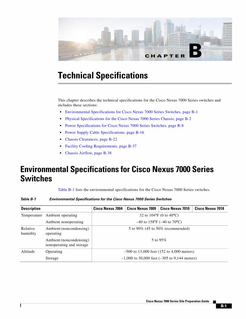
Environmental Specifications for Cisco Nexus 7000 Series Switches
Table B-1 lists the environmental specifications for the Cisco Nexus 7000 Series switches.
Table B-1 Environmental Specifications for the Cisco Nexus 7000 Series Switches
Description Cisco Nexus 7004 Cisco Nexus 7009 Cisco Nexus 7010 Cisco Nexus 7018
Temperature Ambient operating 32 to 104ºF (0 to 40ºC)
Ambient nonoperating –40 to 158ºF (–40 to 70ºC)
Relative humidity
Ambient (noncondensing) operating
5 to 90% (45 to 50% recommended)
Ambient (noncondensing) nonoperating and storage
5 to 95%
Altitude Operating –500 to 13,000 feet (152 to 4,000 meters)
Storage –1,000 to 30,000 feet (–305 to 9,144 meters)
B-1Cisco Nexus 7000 Series Site Preparation Guide

Appendix B Technical SpecificationsPhysical Specifications for the Cisco Nexus 7000 Series Chassis
Physical Specifications for the Cisco Nexus 7000 Series ChassisThe physical specifications differ for the Cisco Nexus 7000 Series chassis depending on the model that you are installing and the type of installation you are doing (you can front mount all models but you can optionally do a center mount of the Cisco Nexus 7004 and 7009 chassis). Table B-2 lists the physical specifications for each model and installation type.
The weights and quantities of the Cisco Nexus 7000 Series chassis are listed in the following tables:
• Cisco Nexus 7004 switch—see Table B-3 on page B-3
• Cisco Nexus 7009 switch —see Table B-4 on page B-3
• Cisco Nexus 7010 switch —see Table B-5 on page B-5
• Cisco Nexus 7018 switch —see Table B-6 on page B-6
The weights in these tables do not include the rack or cabinet that holds the chassis or the interface and power cables. For those weights, see the documentation provided by the manufacturers of those components.
Table B-2 Physical Specifications for Cisco Nexus 7000 Series Chassis
Chassis Width1 Front Depth2 Rear Depth3 Height4
Cisco Nexus 7004 (all mounts)
17.3 inches (43.9 cm) 7 inches (17.8 cm) 24.0 inches (61.0 cm) 12.2 inches (30.9 cm) (7 RU)
Cisco Nexus 7009 (front mount)
17.3 inches (43.9 cm) 7 inches (17.8 cm) 24.0 inches (61.0 cm) 24.5 inches (62.2 cm) (14 RU)
Cisco Nexus 7009 (center mount)
17.3 inches (43.9 cm) 13 inches (33.0 cm) 18.0 inches (45.8 cm) 24.5 inches (62.2 cm) (14 RU)
Cisco Nexus 7010 (all mounts)
17.3 inches (43.9 cm) 7 inches (17.8 cm) 32.0 inches (81.3 cm) 36.75 inches (93.3 cm) (21.0 RU)
Cisco Nexus 7018 (all mounts
17.3 inches (43.9 cm) 7 inches (17.8 cm) 32.0 inches (81.3 cm) 43.75 inches (111.1 cm) (25.0 RU)
1. Width is the minimal clearance required between the two vertical mounting rails inside the rack or cabinet.
2. Front depth is the minimal clearance required between the front-mounting rails and the inside of the front of the rack or cabinet. For all switches, this includes 7 inches (17.8 cm) of space for cabling. For the Cisco Nexus 7009 center-mounted chassis, this distance also includes 6 inches of the chassis, which is offset to the front by the center-mount bracket.
3. Rear depth is the clearance required between the front-mounting rails and the inside of the rear of the rack or cabinet. For front mounted switches, this is the same as the depth of the chassis. For a center-mounted Cisco Nexus 7009 switch, this is 6 inches (15.2 cm) less than the depth of the chassis, which is offset to the front.
4. Height is the clearance required between the top of the bottom support bracket and the top of the chassis that you are installing. If you are installing another chassis above this chassis, its bottom-support brackets must be positioned above this clearance area.
B-2Cisco Nexus 7000 Series Site Preparation Guide
Appendix B Technical SpecificationsPhysical Specifications for the Cisco Nexus 7000 Series Chassis
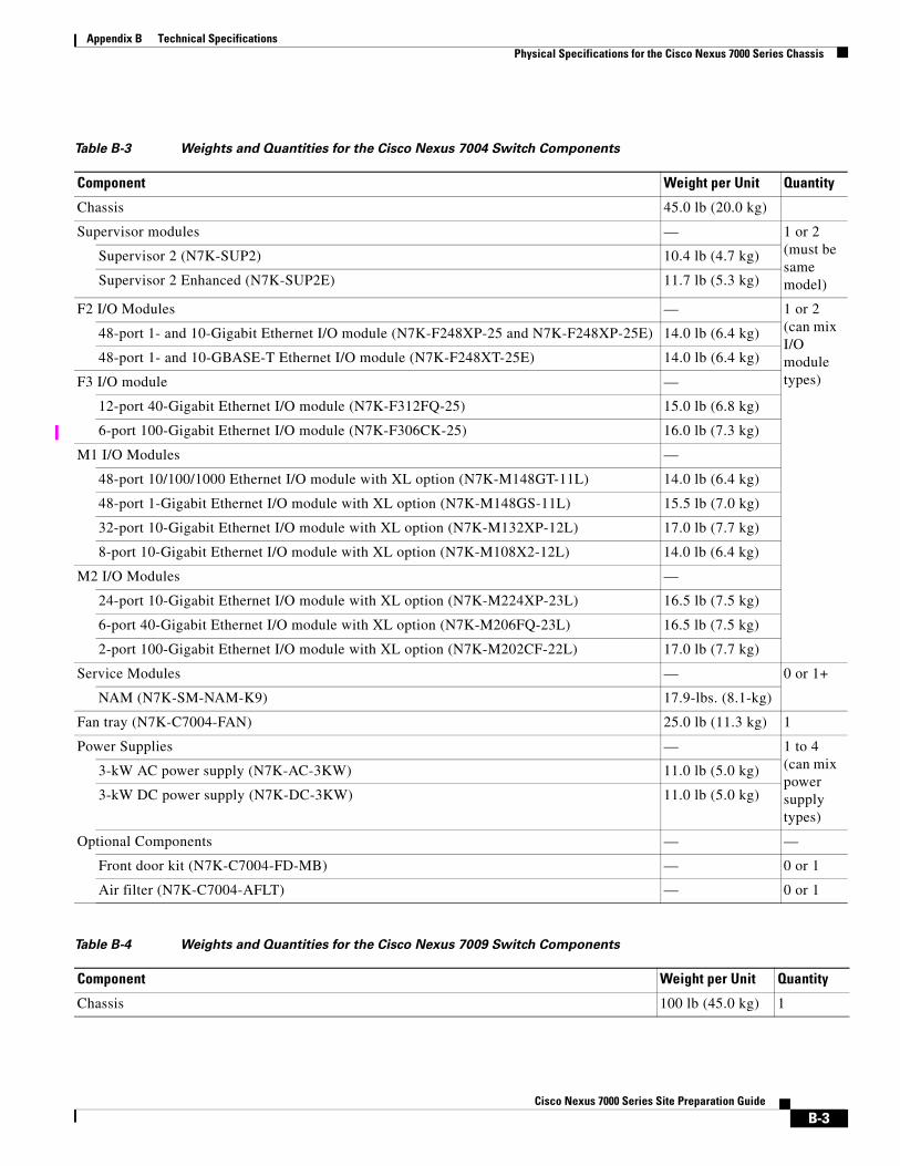
Table B-3 Weights and Quantities for the Cisco Nexus 7004 Switch Components
Component Weight per Unit Quantity
Chassis 45.0 lb (20.0 kg)
Supervisor modules — 1 or 2 (must be same model)
Supervisor 2 (N7K-SUP2) 10.4 lb (4.7 kg)
Supervisor 2 Enhanced (N7K-SUP2E) 11.7 lb (5.3 kg)
F2 I/O Modules — 1 or 2 (can mix I/O module types)
48-port 1- and 10-Gigabit Ethernet I/O module (N7K-F248XP-25 and N7K-F248XP-25E) 14.0 lb (6.4 kg)
48-port 1- and 10-GBASE-T Ethernet I/O module (N7K-F248XT-25E) 14.0 lb (6.4 kg)
F3 I/O module —
12-port 40-Gigabit Ethernet I/O module (N7K-F312FQ-25) 15.0 lb (6.8 kg)
6-port 100-Gigabit Ethernet I/O module (N7K-F306CK-25) 16.0 lb (7.3 kg)
M1 I/O Modules —
48-port 10/100/1000 Ethernet I/O module with XL option (N7K-M148GT-11L) 14.0 lb (6.4 kg)
48-port 1-Gigabit Ethernet I/O module with XL option (N7K-M148GS-11L) 15.5 lb (7.0 kg)
32-port 10-Gigabit Ethernet I/O module with XL option (N7K-M132XP-12L) 17.0 lb (7.7 kg)
8-port 10-Gigabit Ethernet I/O module with XL option (N7K-M108X2-12L) 14.0 lb (6.4 kg)
M2 I/O Modules —
24-port 10-Gigabit Ethernet I/O module with XL option (N7K-M224XP-23L) 16.5 lb (7.5 kg)
6-port 40-Gigabit Ethernet I/O module with XL option (N7K-M206FQ-23L) 16.5 lb (7.5 kg)
2-port 100-Gigabit Ethernet I/O module with XL option (N7K-M202CF-22L) 17.0 lb (7.7 kg)
Service Modules — 0 or 1+
NAM (N7K-SM-NAM-K9) 17.9-lbs. (8.1-kg)
Fan tray (N7K-C7004-FAN) 25.0 lb (11.3 kg) 1
Power Supplies — 1 to 4(can mix power supply types)
3-kW AC power supply (N7K-AC-3KW) 11.0 lb (5.0 kg)
3-kW DC power supply (N7K-DC-3KW) 11.0 lb (5.0 kg)
Optional Components — —
Front door kit (N7K-C7004-FD-MB) — 0 or 1
Air filter (N7K-C7004-AFLT) — 0 or 1
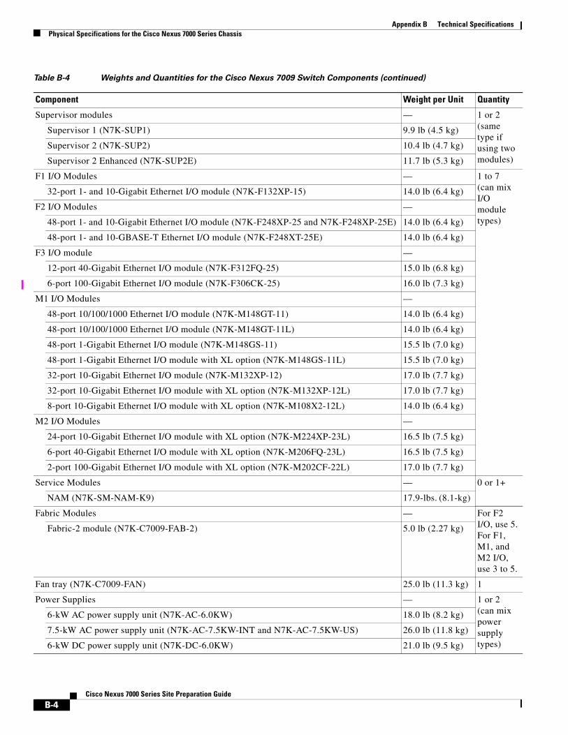
Table B-4 Weights and Quantities for the Cisco Nexus 7009 Switch Components
Component Weight per Unit Quantity
Chassis 100 lb (45.0 kg) 1
B-3Cisco Nexus 7000 Series Site Preparation Guide
Appendix B Technical SpecificationsPhysical Specifications for the Cisco Nexus 7000 Series Chassis
Supervisor modules — 1 or 2 (same type if using two modules)
Supervisor 1 (N7K-SUP1) 9.9 lb (4.5 kg)
Supervisor 2 (N7K-SUP2) 10.4 lb (4.7 kg)
Supervisor 2 Enhanced (N7K-SUP2E) 11.7 lb (5.3 kg)
F1 I/O Modules — 1 to 7 (can mix I/O module types)
32-port 1- and 10-Gigabit Ethernet I/O module (N7K-F132XP-15) 14.0 lb (6.4 kg)
F2 I/O Modules —
48-port 1- and 10-Gigabit Ethernet I/O module (N7K-F248XP-25 and N7K-F248XP-25E) 14.0 lb (6.4 kg)
48-port 1- and 10-GBASE-T Ethernet I/O module (N7K-F248XT-25E) 14.0 lb (6.4 kg)
F3 I/O module —
12-port 40-Gigabit Ethernet I/O module (N7K-F312FQ-25) 15.0 lb (6.8 kg)
6-port 100-Gigabit Ethernet I/O module (N7K-F306CK-25) 16.0 lb (7.3 kg)
M1 I/O Modules —
48-port 10/100/1000 Ethernet I/O module (N7K-M148GT-11) 14.0 lb (6.4 kg)
48-port 10/100/1000 Ethernet I/O module (N7K-M148GT-11L) 14.0 lb (6.4 kg)
48-port 1-Gigabit Ethernet I/O module (N7K-M148GS-11) 15.5 lb (7.0 kg)
48-port 1-Gigabit Ethernet I/O module with XL option (N7K-M148GS-11L) 15.5 lb (7.0 kg)
32-port 10-Gigabit Ethernet I/O module (N7K-M132XP-12) 17.0 lb (7.7 kg)
32-port 10-Gigabit Ethernet I/O module with XL option (N7K-M132XP-12L) 17.0 lb (7.7 kg)
8-port 10-Gigabit Ethernet I/O module with XL option (N7K-M108X2-12L) 14.0 lb (6.4 kg)
M2 I/O Modules —
24-port 10-Gigabit Ethernet I/O module with XL option (N7K-M224XP-23L) 16.5 lb (7.5 kg)
6-port 40-Gigabit Ethernet I/O module with XL option (N7K-M206FQ-23L) 16.5 lb (7.5 kg)
2-port 100-Gigabit Ethernet I/O module with XL option (N7K-M202CF-22L) 17.0 lb (7.7 kg)
Service Modules — 0 or 1+
NAM (N7K-SM-NAM-K9) 17.9-lbs. (8.1-kg)
Fabric Modules — For F2 I/O, use 5.For F1, M1, and M2 I/O, use 3 to 5.
Fabric-2 module (N7K-C7009-FAB-2) 5.0 lb (2.27 kg)
Fan tray (N7K-C7009-FAN) 25.0 lb (11.3 kg) 1
Power Supplies — 1 or 2 (can mix power supply types)
6-kW AC power supply unit (N7K-AC-6.0KW) 18.0 lb (8.2 kg)
7.5-kW AC power supply unit (N7K-AC-7.5KW-INT and N7K-AC-7.5KW-US) 26.0 lb (11.8 kg)
6-kW DC power supply unit (N7K-DC-6.0KW) 21.0 lb (9.5 kg)
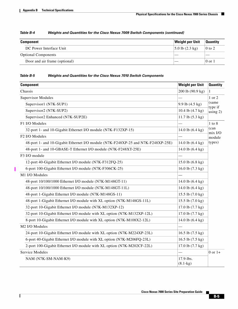
Table B-4 Weights and Quantities for the Cisco Nexus 7009 Switch Components (continued)
Component Weight per Unit Quantity
B-4Cisco Nexus 7000 Series Site Preparation Guide
Appendix B Technical SpecificationsPhysical Specifications for the Cisco Nexus 7000 Series Chassis
DC Power Interface Unit 5.0 lb (2.3 kg) 0 to 2
Optional Components — —
Door and air frame (optional) — 0 or 1
Table B-5 Weights and Quantities for the Cisco Nexus 7010 Switch Components
Component Weight per Unit Quantity
Chassis 200 lb (90.9 kg) 1
Supervisor Modules — 1 or 2 (same type if using 2)
Supervisor1 (N7K-SUP1) 9.9 lb (4.5 kg)
Supervisor2 (N7K-SUP2) 10.4 lb (4.7 kg)
Supervisor2 Enhanced (N7K-SUP2E) 11.7 lb (5.3 kg)
F1 I/O Modules — 1 to 8 (can mix I/O module types)
32-port 1- and 10-Gigabit Ethernet I/O module (N7K-F132XP-15) 14.0 lb (6.4 kg)
F2 I/O Modules —
48-port 1- and 10-Gigabit Ethernet I/O module (N7K-F248XP-25 and N7K-F248XP-25E) 14.0 lb (6.4 kg)
48-port 1- and 10-GBASE-T Ethernet I/O module (N7K-F248XT-25E) 14.0 lb (6.4 kg)
F3 I/O module —
12-port 40-Gigabit Ethernet I/O module (N7K-F312FQ-25) 15.0 lb (6.8 kg)
6-port 100-Gigabit Ethernet I/O module (N7K-F306CK-25) 16.0 lb (7.3 kg)
M1 I/O Modules —
48-port 10/100/1000 Ethernet I/O module (N7K-M148GT-11) 14.0 lb (6.4 kg)
48-port 10/100/1000 Ethernet I/O module (N7K-M148GT-11L) 14.0 lb (6.4 kg)
48-port 1-Gigabit Ethernet I/O module (N7K-M148GS-11) 15.5 lb (7.0 kg)
48-port 1-Gigabit Ethernet I/O module with XL option (N7K-M148GS-11L) 15.5 lb (7.0 kg)
32-port 10-Gigabit Ethernet I/O module (N7K-M132XP-12) 17.0 lb (7.7 kg)
32-port 10-Gigabit Ethernet I/O module with XL option (N7K-M132XP-12L) 17.0 lb (7.7 kg)
8-port 10-Gigabit Ethernet I/O module with XL option (N7K-M108X2-12L) 14.0 lb (6.4 kg)
M2 I/O Modules —
24-port 10-Gigabit Ethernet I/O module with XL option (N7K-M224XP-23L) 16.5 lb (7.5 kg)
6-port 40-Gigabit Ethernet I/O module with XL option (N7K-M206FQ-23L) 16.5 lb (7.5 kg)
2-port 100-Gigabit Ethernet I/O module with XL option (N7K-M202CF-22L) 17.0 lb (7.7 kg)
Service Modules — 0 or 1+
NAM (N7K-SM-NAM-K9) 17.9-lbs. (8.1-kg)
Table B-4 Weights and Quantities for the Cisco Nexus 7009 Switch Components (continued)
Component Weight per Unit Quantity
B-5Cisco Nexus 7000 Series Site Preparation Guide
Appendix B Technical SpecificationsPhysical Specifications for the Cisco Nexus 7000 Series Chassis
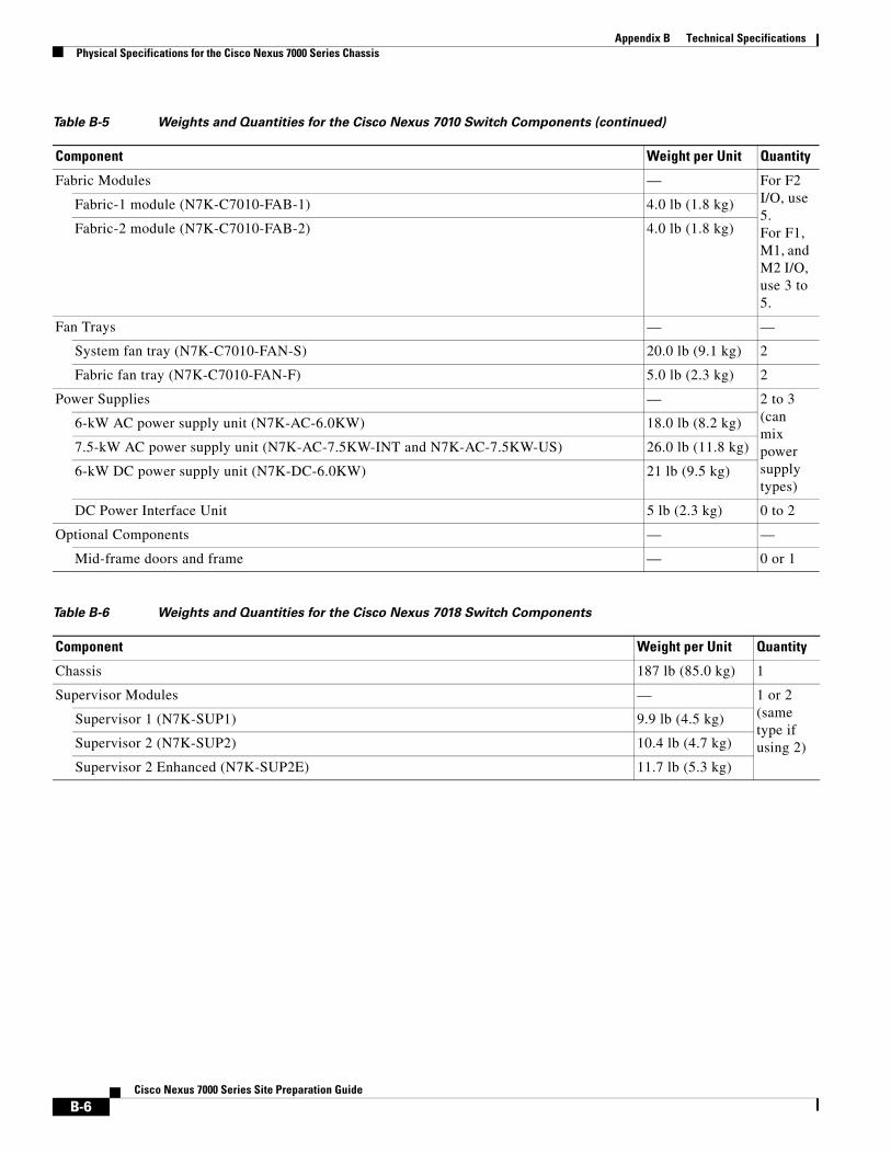
Fabric Modules — For F2 I/O, use 5.For F1, M1, and M2 I/O, use 3 to 5.
Fabric-1 module (N7K-C7010-FAB-1) 4.0 lb (1.8 kg)
Fabric-2 module (N7K-C7010-FAB-2) 4.0 lb (1.8 kg)
Fan Trays — —
System fan tray (N7K-C7010-FAN-S) 20.0 lb (9.1 kg) 2
Fabric fan tray (N7K-C7010-FAN-F) 5.0 lb (2.3 kg) 2
Power Supplies — 2 to 3 (can mix power supply types)
6-kW AC power supply unit (N7K-AC-6.0KW) 18.0 lb (8.2 kg)
7.5-kW AC power supply unit (N7K-AC-7.5KW-INT and N7K-AC-7.5KW-US) 26.0 lb (11.8 kg)
6-kW DC power supply unit (N7K-DC-6.0KW) 21 lb (9.5 kg)
DC Power Interface Unit 5 lb (2.3 kg) 0 to 2
Optional Components — —
Mid-frame doors and frame — 0 or 1
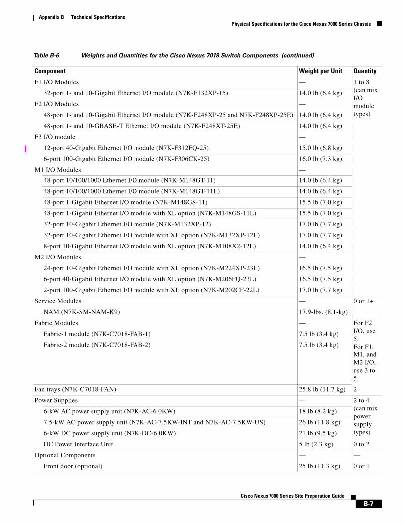
Table B-6 Weights and Quantities for the Cisco Nexus 7018 Switch Components
Component Weight per Unit Quantity
Chassis 187 lb (85.0 kg) 1
Supervisor Modules — 1 or 2 (same type if using 2)
Supervisor 1 (N7K-SUP1) 9.9 lb (4.5 kg)
Supervisor 2 (N7K-SUP2) 10.4 lb (4.7 kg)
Supervisor 2 Enhanced (N7K-SUP2E) 11.7 lb (5.3 kg)
Table B-5 Weights and Quantities for the Cisco Nexus 7010 Switch Components (continued)
Component Weight per Unit Quantity
B-6Cisco Nexus 7000 Series Site Preparation Guide
Appendix B Technical SpecificationsPhysical Specifications for the Cisco Nexus 7000 Series Chassis
F1 I/O Modules — 1 to 8 (can mix I/O module types)
32-port 1- and 10-Gigabit Ethernet I/O module (N7K-F132XP-15) 14.0 lb (6.4 kg)
F2 I/O Modules —
48-port 1- and 10-Gigabit Ethernet I/O module (N7K-F248XP-25 and N7K-F248XP-25E) 14.0 lb (6.4 kg)
48-port 1- and 10-GBASE-T Ethernet I/O module (N7K-F248XT-25E) 14.0 lb (6.4 kg)
F3 I/O module —
12-port 40-Gigabit Ethernet I/O module (N7K-F312FQ-25) 15.0 lb (6.8 kg)
6-port 100-Gigabit Ethernet I/O module (N7K-F306CK-25) 16.0 lb (7.3 kg)
M1 I/O Modules —
48-port 10/100/1000 Ethernet I/O module (N7K-M148GT-11) 14.0 lb (6.4 kg)
48-port 10/100/1000 Ethernet I/O module (N7K-M148GT-11L) 14.0 lb (6.4 kg)
48-port 1-Gigabit Ethernet I/O module (N7K-M148GS-11) 15.5 lb (7.0 kg)
48-port 1-Gigabit Ethernet I/O module with XL option (N7K-M148GS-11L) 15.5 lb (7.0 kg)
32-port 10-Gigabit Ethernet I/O module (N7K-M132XP-12) 17.0 lb (7.7 kg)
32-port 10-Gigabit Ethernet I/O module with XL option (N7K-M132XP-12L) 17.0 lb (7.7 kg)
8-port 10-Gigabit Ethernet I/O module with XL option (N7K-M108X2-12L) 14.0 lb (6.4 kg)
M2 I/O Modules —
24-port 10-Gigabit Ethernet I/O module with XL option (N7K-M224XP-23L) 16.5 lb (7.5 kg)
6-port 40-Gigabit Ethernet I/O module with XL option (N7K-M206FQ-23L) 16.5 lb (7.5 kg)
2-port 100-Gigabit Ethernet I/O module with XL option (N7K-M202CF-22L) 17.0 lb (7.7 kg)
Service Modules — 0 or 1+
NAM (N7K-SM-NAM-K9) 17.9-lbs. (8.1-kg)
Fabric Modules — For F2 I/O, use 5.For F1, M1, and M2 I/O, use 3 to 5.
Fabric-1 module (N7K-C7018-FAB-1) 7.5 lb (3.4 kg)
Fabric-2 module (N7K-C7018-FAB-2) 7.5 lb (3.4 kg)
Fan trays (N7K-C7018-FAN) 25.8 lb (11.7 kg) 2
Power Supplies — 2 to 4 (can mix power supply types)
6-kW AC power supply unit (N7K-AC-6.0KW) 18 lb (8.2 kg)
7.5-kW AC power supply unit (N7K-AC-7.5KW-INT and N7K-AC-7.5KW-US) 26 lb (11.8 kg)
6-kW DC power supply unit (N7K-DC-6.0KW) 21 lb (9.5 kg)
DC Power Interface Unit 5 lb (2.3 kg) 0 to 2
Optional Components — —
Front door (optional) 25 lb (11.3 kg) 0 or 1
Table B-6 Weights and Quantities for the Cisco Nexus 7018 Switch Components (continued)
Component Weight per Unit Quantity
B-7Cisco Nexus 7000 Series Site Preparation Guide

Appendix B Technical SpecificationsPower Specifications for Cisco Nexus 7000 Series Switches
Power Specifications for Cisco Nexus 7000 Series SwitchesThe number of power supplies that a Cisco Nexus 7000 Series switch requires depends on the quantities and types of modules that you include in the switch chassis, the type of power supply units that you are using, and the power redundancy mode that you are using.
The following topics explain how to calculate the switch power requirements and the amount of power available for each type of power supply configuration mode:
• Power Requirements for Switch Components, page B-8
• Power Supply Configuration Modes, page B-12
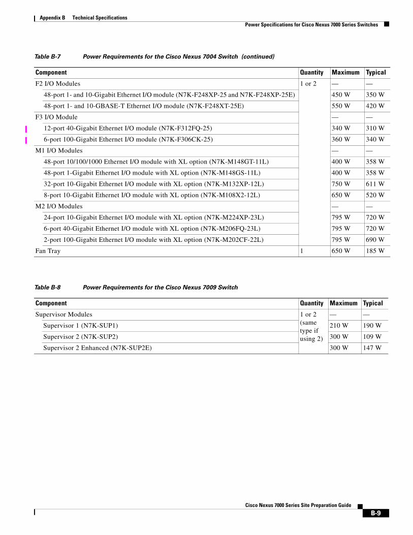
Power Requirements for Switch ComponentsTo determine the power requirements of the Cisco Nexus 7000 Series switches, add the power requirements of each of its components. For each component, multiply the number of its modules by its maximum or typical power requirement. To find the quantities and power requirements for each Cisco Nexus 7000 Series switch, see the following tables:
• Cisco Nexus 7004—see Table B-7
• Cisco Nexus 7009—see Table B-8 on page B-9
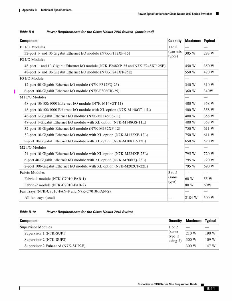
• Cisco Nexus 7010—see Table B-9 on page B-10
• Cisco Nexus 7018—see Table B-10 on page B-11
Table B-7 Power Requirements for the Cisco Nexus 7004 Switch
Component Quantity Maximum Typical
Supervisor Modules 1 or 2 (same type if using 2)
— —
Supervisor 2 (N7K-SUP2) 300 W 109 W
Supervisor 2 Enhanced (N7K-SUP2E) 300 W 147 W
B-8Cisco Nexus 7000 Series Site Preparation Guide
Appendix B Technical SpecificationsPower Specifications for Cisco Nexus 7000 Series Switches
F2 I/O Modules 1 or 2 — —
48-port 1- and 10-Gigabit Ethernet I/O module (N7K-F248XP-25 and N7K-F248XP-25E) 450 W 350 W
48-port 1- and 10-GBASE-T Ethernet I/O module (N7K-F248XT-25E) 550 W 420 W
F3 I/O Module — —
12-port 40-Gigabit Ethernet I/O module (N7K-F312FQ-25) 340 W 310 W
6-port 100-Gigabit Ethernet I/O module (N7K-F306CK-25) 360 W 340 W
M1 I/O Modules — —
48-port 10/100/1000 Ethernet I/O module with XL option (N7K-M148GT-11L) 400 W 358 W
48-port 1-Gigabit Ethernet I/O module with XL option (N7K-M148GS-11L) 400 W 358 W
32-port 10-Gigabit Ethernet I/O module with XL option (N7K-M132XP-12L) 750 W 611 W
8-port 10-Gigabit Ethernet I/O module with XL option (N7K-M108X2-12L) 650 W 520 W
M2 I/O Modules — —
24-port 10-Gigabit Ethernet I/O module with XL option (N7K-M224XP-23L) 795 W 720 W
6-port 40-Gigabit Ethernet I/O module with XL option (N7K-M206FQ-23L) 795 W 720 W
2-port 100-Gigabit Ethernet I/O module with XL option (N7K-M202CF-22L) 795 W 690 W
Fan Tray 1 650 W 185 W
Table B-7 Power Requirements for the Cisco Nexus 7004 Switch (continued)
Component Quantity Maximum Typical
Table B-8 Power Requirements for the Cisco Nexus 7009 Switch
Component Quantity Maximum Typical
Supervisor Modules 1 or 2 (same type if using 2)
— —
Supervisor 1 (N7K-SUP1) 210 W 190 W
Supervisor 2 (N7K-SUP2) 300 W 109 W
Supervisor 2 Enhanced (N7K-SUP2E) 300 W 147 W
B-9Cisco Nexus 7000 Series Site Preparation Guide

Appendix B Technical SpecificationsPower Specifications for Cisco Nexus 7000 Series Switches
F1 I/O Modules 1 to 7 — —
32-port 1- and 10-Gigabit Ethernet I/O module (N7K-F132XP-15) 385 W 283 W
F2 I/O Modules — —
48-port 1- and 10-Gigabit Ethernet I/O module (N7K-F248XP-25 and N7K-F248XP-25E) 450 W 350 W
48-port 1- and 10-GBASE-T Ethernet I/O module (N7K-F248XT-25E) 550 W 420 W
F3 I/O Module — —
12-port 40-Gigabit Ethernet I/O module (N7K-F312FQ-25) 340 W 310 W
6-port 100-Gigabit Ethernet I/O module (N7K-F306CK-25) 360 W 340W
M1 I/O Modules — —
48-port 10/100/1000 Ethernet I/O module (N7K-M148GT-11) 400 W 358 W
48-port 10/100/1000 Ethernet I/O module with XL option (N7K-M148GT-11L) 400 W 358 W
48-port 1-Gigabit Ethernet I/O module (N7K-M1148GS-11) 400 W 358 W
48-port 1-Gigabit Ethernet I/O module with XL option (N7K-M148GS-11L) 400 W 358 W
32-port 10-Gigabit Ethernet I/O module (N7K-M132XP-12) 750 W 611 W
32-port 10-Gigabit Ethernet I/O module with XL option (N7K-M132XP-12L) 750 W 611 W
8-port 10-Gigabit Ethernet I/O module with XL option (N7K-M108X2-12L) 650 W 520 W
M2 I/O Modules — —
24-port 10-Gigabit Ethernet I/O module with XL option (N7K-M224XP-23L) 795 W 720 W
6-port 40-Gigabit Ethernet I/O module with XL option (N7K-M206FQ-23L) 795 W 720 W
2-port 100-Gigabit Ethernet I/O module with XL option (N7K-M202CF-22L) 795 W 690 W
Fabric Modules
3 to 5
— —
Fabric-2 module (N7K-C7009-FAB-2) 70 W 55 W
Fan Trays
—
— —
All fan trays (total) (N7K-C7009-FAN) 650 W 190 W
Table B-8 Power Requirements for the Cisco Nexus 7009 Switch (continued)
Component Quantity Maximum Typical
Table B-9 Power Requirements for the Cisco Nexus 7010 Switch
Component Quantity Maximum Typical
Supervisor Modules 1 or 2 (same type if using 2)
— —
Supervisor 1 (N7K-SUP1) 210 W 190 W
Supervisor 2 (N7K-SUP2) 300 W 109 W
Supervisor 2 Enhanced (N7K-SUP2E) 300 W 147 W
B-10Cisco Nexus 7000 Series Site Preparation Guide
Appendix B Technical SpecificationsPower Specifications for Cisco Nexus 7000 Series Switches
F1 I/O Modules 1 to 8 (can mix types)
— —
32-port 1- and 10-Gigabit Ethernet I/O module (N7K-F132XP-15) 385 W 283 W
F2 I/O Modules — —
48-port 1- and 10-Gigabit Ethernet I/O module (N7K-F248XP-25 and N7K-F248XP-25E) 450 W 350 W
48-port 1- and 10-Gigabit Ethernet I/O module (N7K-F248XT-25E) 550 W 420 W
F3 I/O Module — —
12-port 40-Gigabit Ethernet I/O module (N7K-F312FQ-25) 340 W 310 W
6-port 100-Gigabit Ethernet I/O module (N7K-F306CK-25) 360 W 340W
M1 I/O Modules — —
48-port 10/100/1000 Ethernet I/O module (N7K-M148GT-11) 400 W 358 W
48-port 10/100/1000 Ethernet I/O module with XL option (N7K-M148GT-11L) 400 W 358 W
48-port 1-Gigabit Ethernet I/O module (N7K-M1148GS-11) 400 W 358 W
48-port 1-Gigabit Ethernet I/O module with XL option (N7K-M148GS-11L) 400 W 358 W
32-port 10-Gigabit Ethernet I/O module (N7K-M132XP-12) 750 W 611 W
32-port 10-Gigabit Ethernet I/O module with XL option (N7K-M132XP-12L) 750 W 611 W
8-port 10-Gigabit Ethernet I/O module with XL option (N7K-M108X2-12L) 650 W 520 W
M2 I/O Modules — —
24-port 10-Gigabit Ethernet I/O module with XL option (N7K-M224XP-23L) 795 W 720 W
6-port 40-Gigabit Ethernet I/O module with XL option (N7K-M206FQ-23L) 795 W 720 W
2-port 100-Gigabit Ethernet I/O module with XL option (N7K-M202CF-22L) 795 W 690 W
Fabric Modules 3 to 5 (same type)
— —
Fabric-1 module (N7K-C7010-FAB-1) 60 W 55 W
Fabric-2 module (N7K-C7010-FAB-2) 80 W 60W
Fan Trays (N7K-C7010-FAN-F and N7K-C7010-FAN-S)
—
— —
All fan trays (total) 2184 W 300 W
Table B-10 Power Requirements for the Cisco Nexus 7018 Switch
Component Quantity Maximum Typical
Supervisor Modules 1 or 2 (same type if using 2)
— —
Supervisor 1 (N7K-SUP1) 210 W 190 W
Supervisor 2 (N7K-SUP2) 300 W 109 W
Supervisor 2 Enhanced (N7K-SUP2E) 300 W 147 W
Table B-9 Power Requirements for the Cisco Nexus 7010 Switch (continued)
Component Quantity Maximum Typical
B-11Cisco Nexus 7000 Series Site Preparation Guide
Appendix B Technical SpecificationsPower Specifications for Cisco Nexus 7000 Series Switches
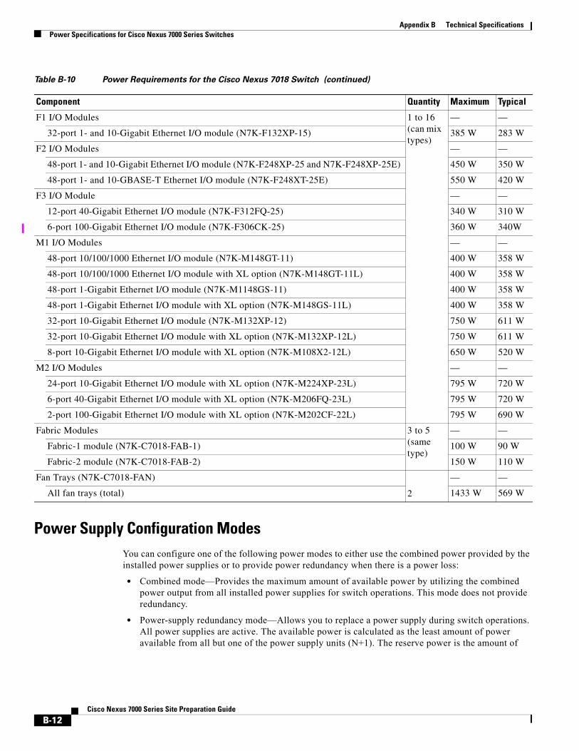
Power Supply Configuration ModesYou can configure one of the following power modes to either use the combined power provided by the installed power supplies or to provide power redundancy when there is a power loss:
• Combined mode—Provides the maximum amount of available power by utilizing the combined power output from all installed power supplies for switch operations. This mode does not provide redundancy.
• Power-supply redundancy mode—Allows you to replace a power supply during switch operations. All power supplies are active. The available power is calculated as the least amount of power available from all but one of the power supply units (N+1). The reserve power is the amount of
F1 I/O Modules 1 to 16 (can mix types)
— —
32-port 1- and 10-Gigabit Ethernet I/O module (N7K-F132XP-15) 385 W 283 W
F2 I/O Modules — —
48-port 1- and 10-Gigabit Ethernet I/O module (N7K-F248XP-25 and N7K-F248XP-25E) 450 W 350 W
48-port 1- and 10-GBASE-T Ethernet I/O module (N7K-F248XT-25E) 550 W 420 W
F3 I/O Module — —
12-port 40-Gigabit Ethernet I/O module (N7K-F312FQ-25) 340 W 310 W
6-port 100-Gigabit Ethernet I/O module (N7K-F306CK-25) 360 W 340W
M1 I/O Modules — —
48-port 10/100/1000 Ethernet I/O module (N7K-M148GT-11) 400 W 358 W
48-port 10/100/1000 Ethernet I/O module with XL option (N7K-M148GT-11L) 400 W 358 W
48-port 1-Gigabit Ethernet I/O module (N7K-M1148GS-11) 400 W 358 W
48-port 1-Gigabit Ethernet I/O module with XL option (N7K-M148GS-11L) 400 W 358 W
32-port 10-Gigabit Ethernet I/O module (N7K-M132XP-12) 750 W 611 W
32-port 10-Gigabit Ethernet I/O module with XL option (N7K-M132XP-12L) 750 W 611 W
8-port 10-Gigabit Ethernet I/O module with XL option (N7K-M108X2-12L) 650 W 520 W
M2 I/O Modules — —
24-port 10-Gigabit Ethernet I/O module with XL option (N7K-M224XP-23L) 795 W 720 W
6-port 40-Gigabit Ethernet I/O module with XL option (N7K-M206FQ-23L) 795 W 720 W
2-port 100-Gigabit Ethernet I/O module with XL option (N7K-M202CF-22L) 795 W 690 W
Fabric Modules 3 to 5 (same type)
— —
Fabric-1 module (N7K-C7018-FAB-1) 100 W 90 W
Fabric-2 module (N7K-C7018-FAB-2) 150 W 110 W
Fan Trays (N7K-C7018-FAN)
2
— —
All fan trays (total) 1433 W 569 W
Table B-10 Power Requirements for the Cisco Nexus 7018 Switch (continued)
Component Quantity Maximum Typical
B-12Cisco Nexus 7000 Series Site Preparation Guide
Appendix B Technical SpecificationsPower Specifications for Cisco Nexus 7000 Series Switches
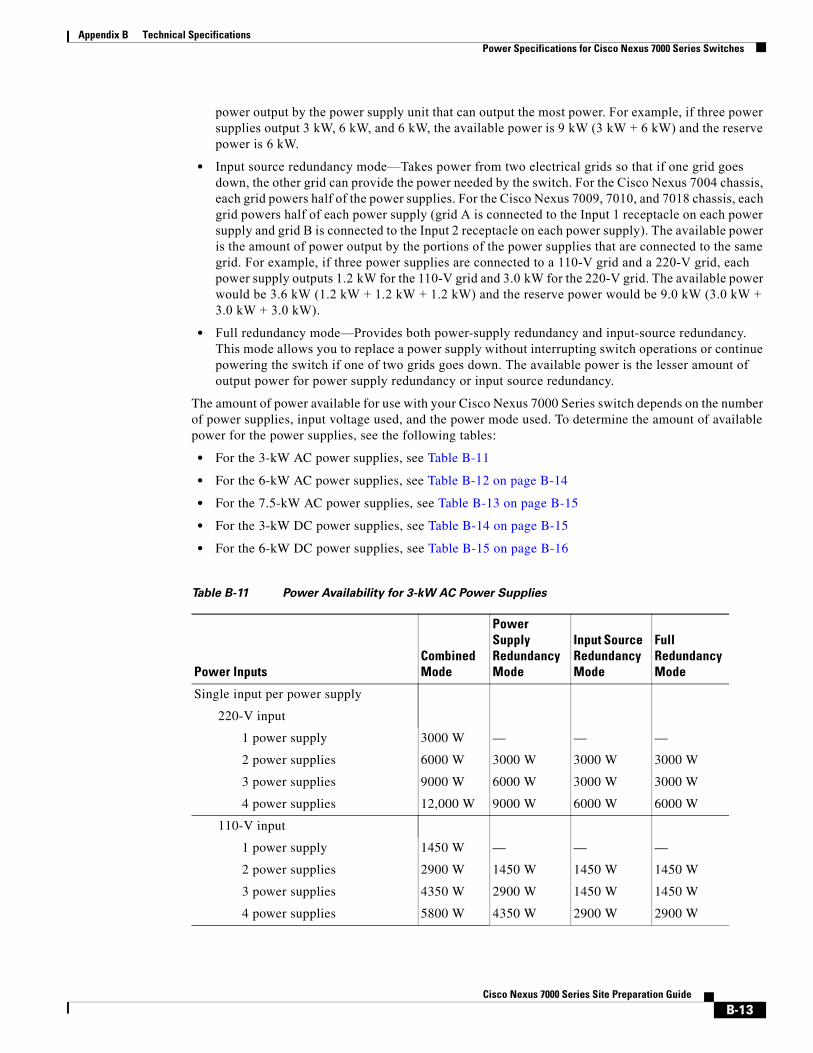
power output by the power supply unit that can output the most power. For example, if three power supplies output 3 kW, 6 kW, and 6 kW, the available power is 9 kW (3 kW + 6 kW) and the reserve power is 6 kW.
• Input source redundancy mode—Takes power from two electrical grids so that if one grid goes down, the other grid can provide the power needed by the switch. For the Cisco Nexus 7004 chassis, each grid powers half of the power supplies. For the Cisco Nexus 7009, 7010, and 7018 chassis, each grid powers half of each power supply (grid A is connected to the Input 1 receptacle on each power supply and grid B is connected to the Input 2 receptacle on each power supply). The available power is the amount of power output by the portions of the power supplies that are connected to the same grid. For example, if three power supplies are connected to a 110-V grid and a 220-V grid, each power supply outputs 1.2 kW for the 110-V grid and 3.0 kW for the 220-V grid. The available power would be 3.6 kW (1.2 kW + 1.2 kW + 1.2 kW) and the reserve power would be 9.0 kW (3.0 kW + 3.0 kW + 3.0 kW).
• Full redundancy mode—Provides both power-supply redundancy and input-source redundancy. This mode allows you to replace a power supply without interrupting switch operations or continue powering the switch if one of two grids goes down. The available power is the lesser amount of output power for power supply redundancy or input source redundancy.
The amount of power available for use with your Cisco Nexus 7000 Series switch depends on the number of power supplies, input voltage used, and the power mode used. To determine the amount of available power for the power supplies, see the following tables:
• For the 3-kW AC power supplies, see Table B-11
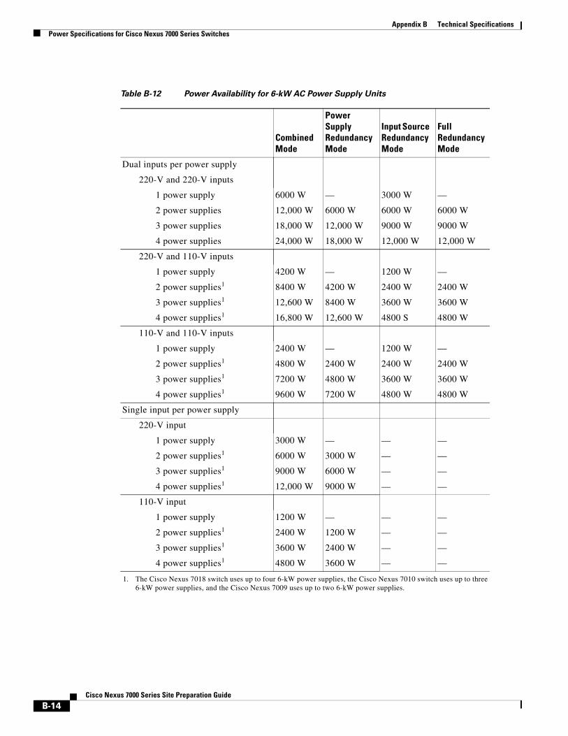
• For the 6-kW AC power supplies, see Table B-12 on page B-14
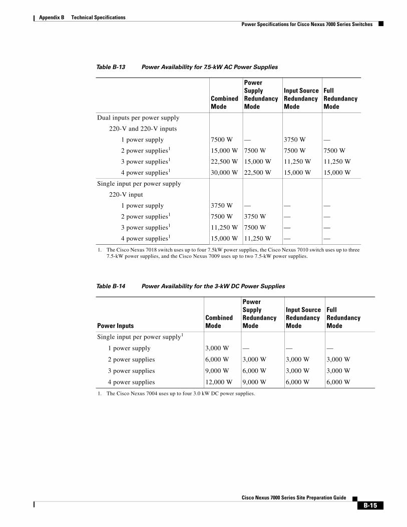
• For the 7.5-kW AC power supplies, see Table B-13 on page B-15
• For the 3-kW DC power supplies, see Table B-14 on page B-15
• For the 6-kW DC power supplies, see Table B-15 on page B-16
Table B-11 Power Availability for 3-kW AC Power Supplies
Power InputsCombined Mode
Power Supply Redundancy Mode
Input Source Redundancy Mode
Full Redundancy Mode
Single input per power supply
220-V input
1 power supply 3000 W — — —
2 power supplies 6000 W 3000 W 3000 W 3000 W
3 power supplies 9000 W 6000 W 3000 W 3000 W
4 power supplies 12,000 W 9000 W 6000 W 6000 W
110-V input
1 power supply 1450 W — — —
2 power supplies 2900 W 1450 W 1450 W 1450 W
3 power supplies 4350 W 2900 W 1450 W 1450 W
4 power supplies 5800 W 4350 W 2900 W 2900 W
B-13Cisco Nexus 7000 Series Site Preparation Guide
Appendix B Technical SpecificationsPower Specifications for Cisco Nexus 7000 Series Switches
Table B-12 Power Availability for 6-kW AC Power Supply Units
Combined Mode
Power Supply Redundancy Mode
Input Source Redundancy Mode
Full Redundancy Mode
Dual inputs per power supply
220-V and 220-V inputs
1 power supply 6000 W — 3000 W —
2 power supplies 12,000 W 6000 W 6000 W 6000 W
3 power supplies 18,000 W 12,000 W 9000 W 9000 W
4 power supplies 24,000 W 18,000 W 12,000 W 12,000 W
220-V and 110-V inputs
1 power supply 4200 W — 1200 W —
2 power supplies1 8400 W 4200 W 2400 W 2400 W
3 power supplies1 12,600 W 8400 W 3600 W 3600 W
4 power supplies1 16,800 W 12,600 W 4800 S 4800 W
110-V and 110-V inputs
1 power supply 2400 W — 1200 W —
2 power supplies1 4800 W 2400 W 2400 W 2400 W
3 power supplies1 7200 W 4800 W 3600 W 3600 W
4 power supplies1 9600 W 7200 W 4800 W 4800 W
Single input per power supply
220-V input
1 power supply 3000 W — — —
2 power supplies1 6000 W 3000 W — —
3 power supplies1 9000 W 6000 W — —
4 power supplies1 12,000 W 9000 W — —
110-V input
1 power supply 1200 W — — —
2 power supplies1 2400 W 1200 W — —
3 power supplies1 3600 W 2400 W — —
4 power supplies1 4800 W 3600 W — —
1. The Cisco Nexus 7018 switch uses up to four 6-kW power supplies, the Cisco Nexus 7010 switch uses up to three 6-kW power supplies, and the Cisco Nexus 7009 uses up to two 6-kW power supplies.
B-14Cisco Nexus 7000 Series Site Preparation Guide
Appendix B Technical SpecificationsPower Specifications for Cisco Nexus 7000 Series Switches
Table B-13 Power Availability for 7.5-kW AC Power Supplies
CombinedMode
Power SupplyRedundancyMode
Input SourceRedundancyMode
FullRedundancyMode
Dual inputs per power supply
220-V and 220-V inputs
1 power supply 7500 W — 3750 W —
2 power supplies1 15,000 W 7500 W 7500 W 7500 W
3 power supplies1 22,500 W 15,000 W 11,250 W 11,250 W
4 power supplies1 30,000 W 22,500 W 15,000 W 15,000 W
Single input per power supply
220-V input
1 power supply 3750 W — — —
2 power supplies1 7500 W 3750 W — —
3 power supplies1 11,250 W 7500 W — —
4 power supplies1 15,000 W 11,250 W — —
1. The Cisco Nexus 7018 switch uses up to four 7.5kW power supplies, the Cisco Nexus 7010 switch uses up to three 7.5-kW power supplies, and the Cisco Nexus 7009 uses up to two 7.5-kW power supplies.
Table B-14 Power Availability for the 3-kW DC Power Supplies
Power InputsCombinedMode
Power SupplyRedundancyMode
Input SourceRedundancyMode
FullRedundancyMode
Single input per power supply1
1 power supply
2 power supplies
3 power supplies
4 power supplies
3,000 W
6,000 W
9,000 W
12,000 W
—
3,000 W
6,000 W
9,000 W
—
3,000 W
3,000 W
6,000 W
—
3,000 W
3,000 W
6,000 W
1. The Cisco Nexus 7004 uses up to four 3.0 kW DC power supplies.
B-15Cisco Nexus 7000 Series Site Preparation Guide
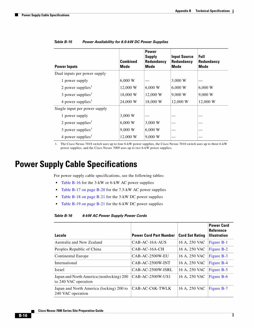
Appendix B Technical SpecificationsPower Supply Cable Specifications
Power Supply Cable SpecificationsFor power supply cable specifications, see the following tables:
• Table B-16 for the 3-kW or 6-kW AC power supplies
• Table B-17 on page B-20 for the 7.5-kW AC power supplies
• Table B-18 on page B-21 for the 3-kW DC power supplies
• Table B-19 on page B-21 for the 6-kW DC power supplies
Table B-15 Power Availability for 6.0-kW DC Power Supplies
Power InputsCombinedMode
Power SupplyRedundancyMode
Input SourceRedundancyMode
FullRedundancyMode
Dual inputs per power supply
1 power supply
2 power supplies1
3 power supplies1
4 power supplies1
6,000 W
12,000 W
18,000 W
24,000 W
—
6,000 W
12,000 W
18,000 W
3,000 W
6,000 W
9,000 W
12,000 W
—
6,000 W
9,000 W
12,000 W
Single input per power supply
1 power supply
2 power supplies1
3 power supplies1
4 power supplies1
3,000 W
6,000 W
9,000 W
12,000 W
—
3,000 W
6,000 W
9,000 W
—
—
—
—
—
—
—
—
1. The Cisco Nexus 7018 switch uses up to four 6-kW power supplies, the Cisco Nexus 7010 switch uses up to three 6-kW power supplies, and the Cisco Nexus 7009 uses up to two 6-kW power supplies.
Table B-16 6-kW AC Power Supply Power Cords
Locale Power Cord Part Number Cord Set Rating
Power Cord Reference Illustration
Australia and New Zealand CAB-AC-16A-AUS 16 A, 250 VAC Figure B-1
Peoples Republic of China CAB-AC-16A-CH 16 A, 250 VAC Figure B-2
Continental Europe CAB-AC-2500W-EU 16 A, 250 VAC Figure B-3
International CAB-AC-2500W-INT 16 A, 250 VAC Figure B-4
Israel CAB-AC-2500W-ISRL 16 A, 250 VAC Figure B-5
Japan and North America (nonlocking) 200 to 240 VAC operation
CAB-AC-2500W-US1 16 A, 250 VAC Figure B-6
Japan and North America (locking) 200 to 240 VAC operation
CAB-AC-C6K-TWLK 16 A, 250 VAC Figure B-7
B-16Cisco Nexus 7000 Series Site Preparation Guide
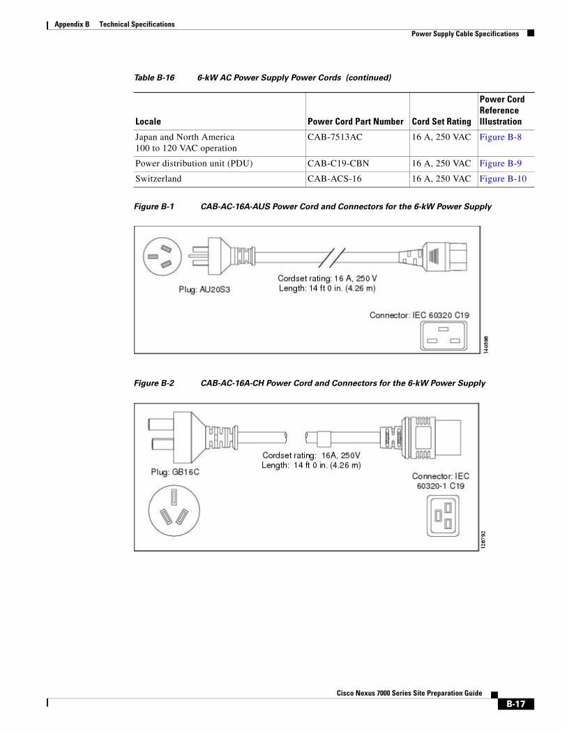
Appendix B Technical SpecificationsPower Supply Cable Specifications
Figure B-1 CAB-AC-16A-AUS Power Cord and Connectors for the 6-kW Power Supply
Figure B-2 CAB-AC-16A-CH Power Cord and Connectors for the 6-kW Power Supply
Japan and North America 100 to 120 VAC operation
CAB-7513AC 16 A, 250 VAC Figure B-8
Power distribution unit (PDU) CAB-C19-CBN 16 A, 250 VAC Figure B-9
Switzerland CAB-ACS-16 16 A, 250 VAC Figure B-10
Table B-16 6-kW AC Power Supply Power Cords (continued)
Locale Power Cord Part Number Cord Set Rating
Power Cord Reference Illustration
B-17Cisco Nexus 7000 Series Site Preparation Guide
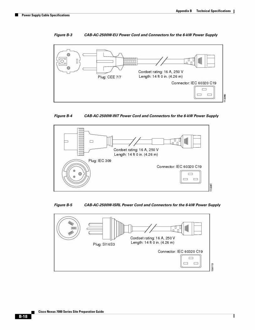
Appendix B Technical SpecificationsPower Supply Cable Specifications
Figure B-3 CAB-AC-2500W-EU Power Cord and Connectors for the 6-kW Power Supply
Figure B-4 CAB-AC-2500W-INT Power Cord and Connectors for the 6-kW Power Supply
Figure B-5 CAB-AC-2500W-ISRL Power Cord and Connectors for the 6-kW Power Supply
B-18Cisco Nexus 7000 Series Site Preparation Guide
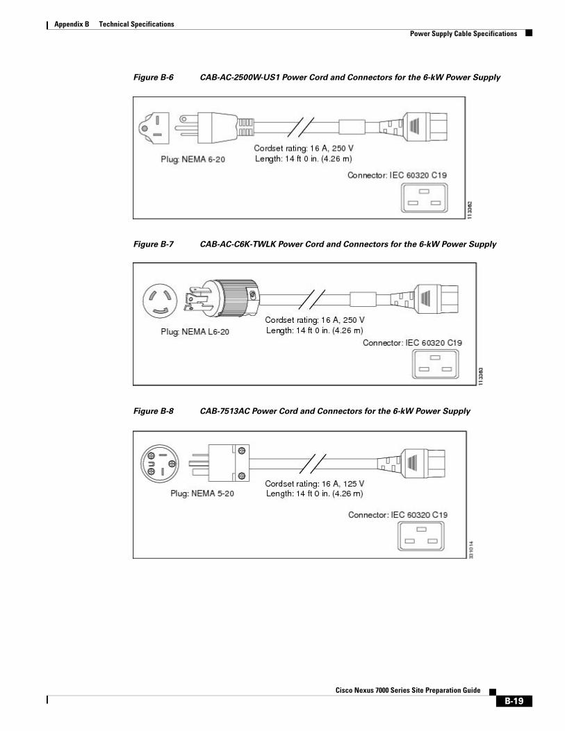
Appendix B Technical SpecificationsPower Supply Cable Specifications
Figure B-6 CAB-AC-2500W-US1 Power Cord and Connectors for the 6-kW Power Supply
Figure B-7 CAB-AC-C6K-TWLK Power Cord and Connectors for the 6-kW Power Supply
Figure B-8 CAB-7513AC Power Cord and Connectors for the 6-kW Power Supply
B-19Cisco Nexus 7000 Series Site Preparation Guide
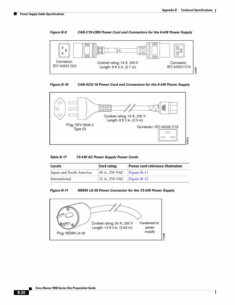
Appendix B Technical SpecificationsPower Supply Cable Specifications
Figure B-9 CAB-C19-CBN Power Cord and Connectors for the 6-kW Power Supply
Figure B-10 CAB-ACS-16 Power Cord and Connectors for the 6-kW Power Supply
Figure B-11 NEMA L6-30 Power Connector for the 7.5-kW Power Supply
Table B-17 7.5-kW AC Power Supply Power Cords
Locale Cord rating Power cord reference illustration
Japan and North America 30 A, 250 VAC Figure B-11
International 32 A, 250 VAC Figure B-12
B-20Cisco Nexus 7000 Series Site Preparation Guide
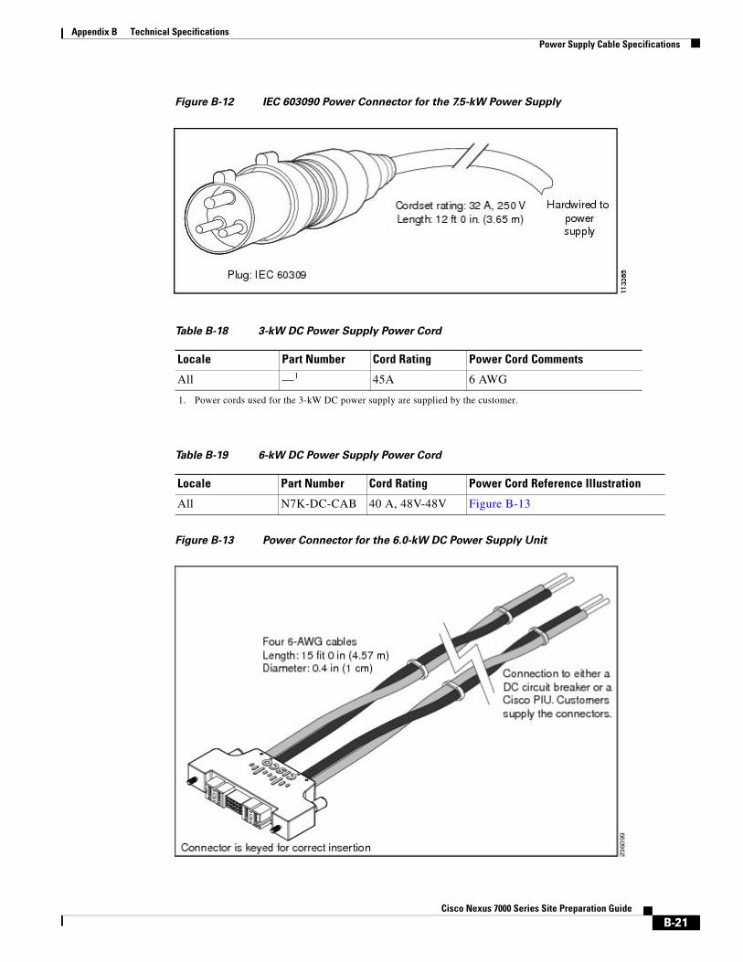
Appendix B Technical SpecificationsPower Supply Cable Specifications
Figure B-12 IEC 603090 Power Connector for the 7.5-kW Power Supply
Figure B-13 Power Connector for the 6.0-kW DC Power Supply Unit
Table B-18 3-kW DC Power Supply Power Cord
Locale Part Number Cord Rating Power Cord Comments
All —1 45A 6 AWG
1. Power cords used for the 3-kW DC power supply are supplied by the customer.
Table B-19 6-kW DC Power Supply Power Cord
Locale Part Number Cord Rating Power Cord Reference Illustration
All N7K-DC-CAB 40 A, 48V-48V Figure B-13
B-21Cisco Nexus 7000 Series Site Preparation Guide
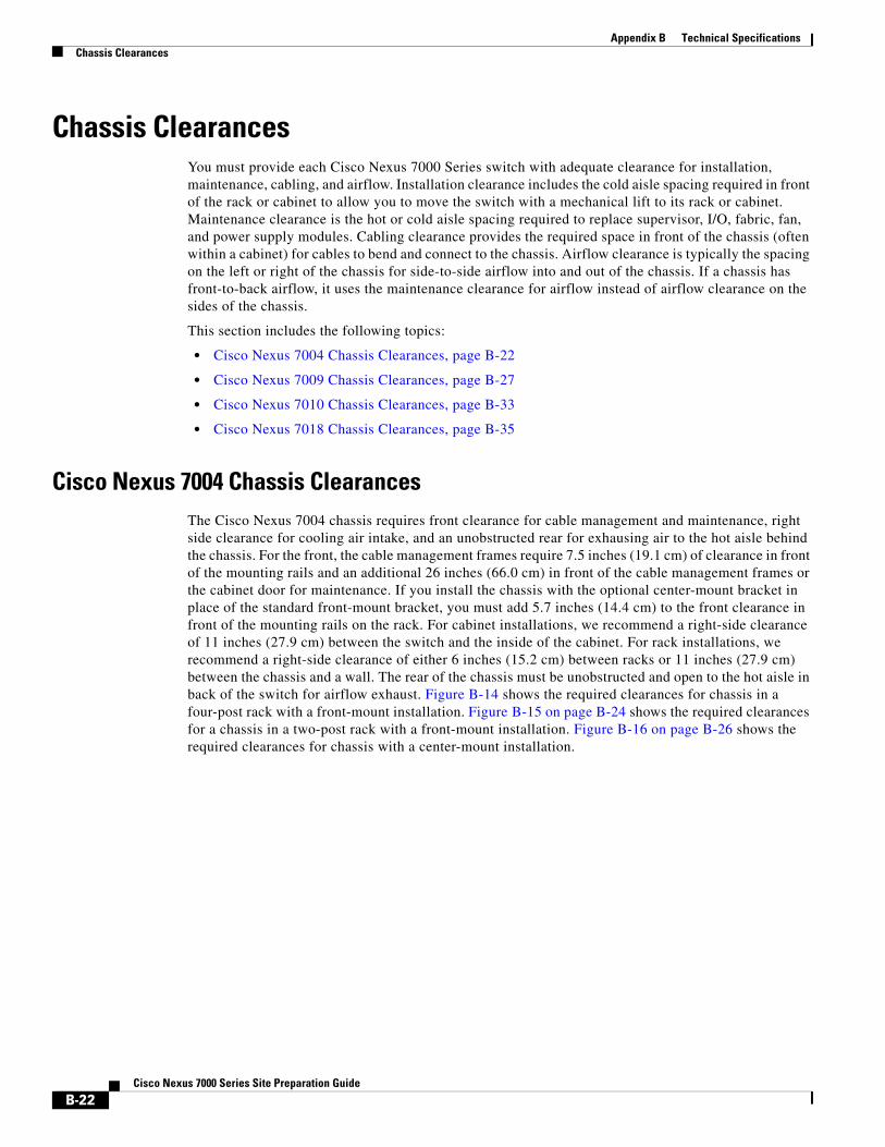
Appendix B Technical SpecificationsChassis Clearances
Chassis ClearancesYou must provide each Cisco Nexus 7000 Series switch with adequate clearance for installation, maintenance, cabling, and airflow. Installation clearance includes the cold aisle spacing required in front of the rack or cabinet to allow you to move the switch with a mechanical lift to its rack or cabinet. Maintenance clearance is the hot or cold aisle spacing required to replace supervisor, I/O, fabric, fan, and power supply modules. Cabling clearance provides the required space in front of the chassis (often within a cabinet) for cables to bend and connect to the chassis. Airflow clearance is typically the spacing on the left or right of the chassis for side-to-side airflow into and out of the chassis. If a chassis has front-to-back airflow, it uses the maintenance clearance for airflow instead of airflow clearance on the sides of the chassis.
This section includes the following topics:
• Cisco Nexus 7004 Chassis Clearances, page B-22
• Cisco Nexus 7009 Chassis Clearances, page B-27
• Cisco Nexus 7010 Chassis Clearances, page B-33
• Cisco Nexus 7018 Chassis Clearances, page B-35
Cisco Nexus 7004 Chassis ClearancesThe Cisco Nexus 7004 chassis requires front clearance for cable management and maintenance, right side clearance for cooling air intake, and an unobstructed rear for exhausing air to the hot aisle behind the chassis. For the front, the cable management frames require 7.5 inches (19.1 cm) of clearance in front of the mounting rails and an additional 26 inches (66.0 cm) in front of the cable management frames or the cabinet door for maintenance. If you install the chassis with the optional center-mount bracket in place of the standard front-mount bracket, you must add 5.7 inches (14.4 cm) to the front clearance in front of the mounting rails on the rack. For cabinet installations, we recommend a right-side clearance of 11 inches (27.9 cm) between the switch and the inside of the cabinet. For rack installations, we recommend a right-side clearance of either 6 inches (15.2 cm) between racks or 11 inches (27.9 cm) between the chassis and a wall. The rear of the chassis must be unobstructed and open to the hot aisle in back of the switch for airflow exhaust. Figure B-14 shows the required clearances for chassis in a four-post rack with a front-mount installation. Figure B-15 on page B-24 shows the required clearances for a chassis in a two-post rack with a front-mount installation. Figure B-16 on page B-26 shows the required clearances for chassis with a center-mount installation.
B-22Cisco Nexus 7000 Series Site Preparation Guide
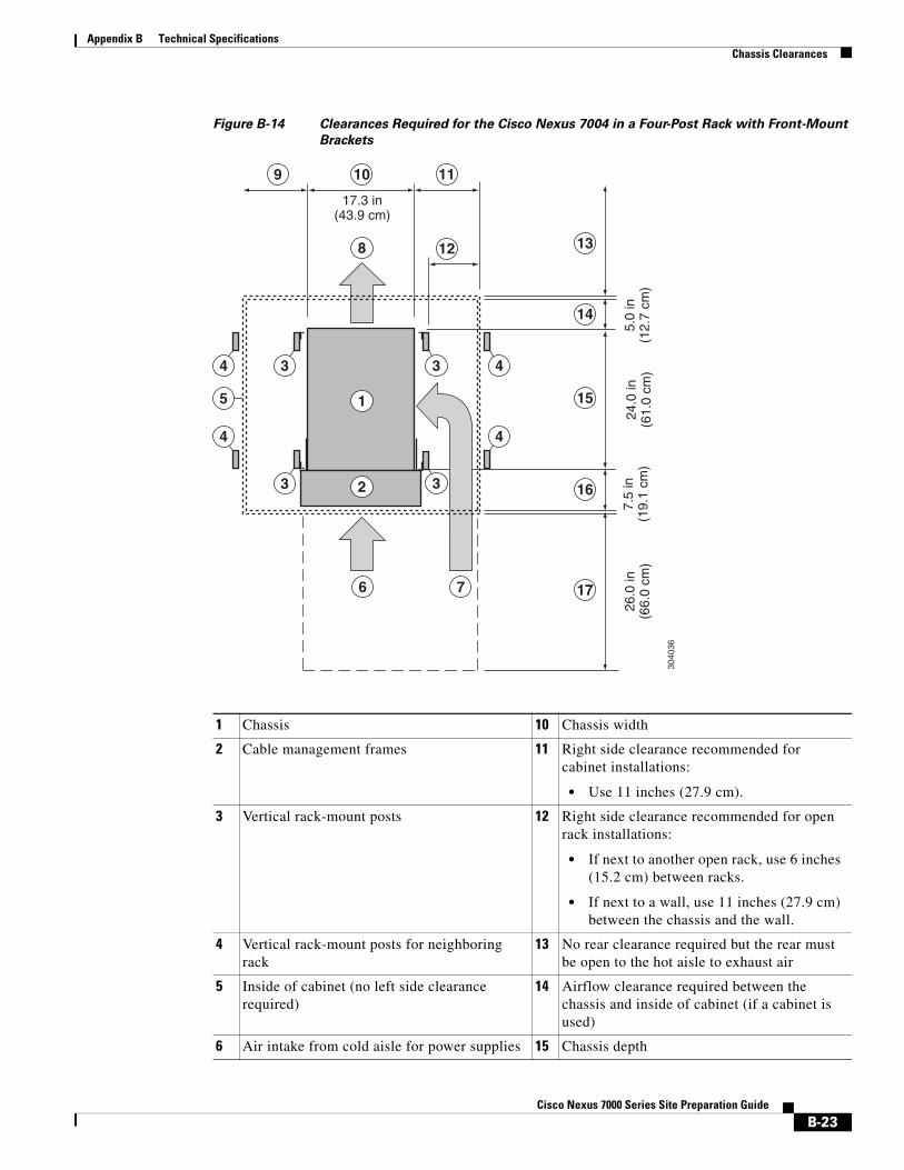
Appendix B Technical SpecificationsChassis Clearances
Figure B-14 Clearances Required for the Cisco Nexus 7004 in a Four-Post Rack with Front-Mount
Brackets
13
14
15
16
17
5
10 119
3040
36
17.3 in(43.9 cm)
12
24.0
in(6
1.0
cm)
7.5
in(1
9.1
cm)
26.0
in(6
6.0
cm)
5.0
in(1
2.7
cm)
1
8
6 7
23
3
4
4
4
43
3
1 Chassis 10 Chassis width
2 Cable management frames 11 Right side clearance recommended for cabinet installations:
• Use 11 inches (27.9 cm).
3 Vertical rack-mount posts 12 Right side clearance recommended for open rack installations:
• If next to another open rack, use 6 inches (15.2 cm) between racks.
• If next to a wall, use 11 inches (27.9 cm) between the chassis and the wall.
4 Vertical rack-mount posts for neighboring rack
13 No rear clearance required but the rear must be open to the hot aisle to exhaust air
5 Inside of cabinet (no left side clearance required)
14 Airflow clearance required between the chassis and inside of cabinet (if a cabinet is used)
6 Air intake from cold aisle for power supplies 15 Chassis depth
B-23Cisco Nexus 7000 Series Site Preparation Guide
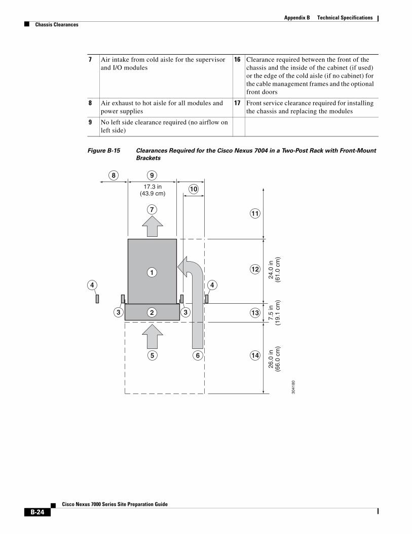
Appendix B Technical SpecificationsChassis Clearances
Figure B-15 Clearances Required for the Cisco Nexus 7004 in a Two-Post Rack with Front-Mount
Brackets
7 Air intake from cold aisle for the supervisor and I/O modules
16 Clearance required between the front of the chassis and the inside of the cabinet (if used) or the edge of the cold aisle (if no cabinet) for the cable management frames and the optional front doors
8 Air exhaust to hot aisle for all modules and power supplies
17 Front service clearance required for installing the chassis and replacing the modules
9 No left side clearance required (no airflow on left side)
17.3 in(43.9 cm)
24.0
in(6
1.0
cm)
7.5
in(1
9.1
cm)
26.0
in(6
6.0
cm)
1
7
9
10
11
12
13
1465
8
23 3
3041
80
4 4
B-24Cisco Nexus 7000 Series Site Preparation Guide
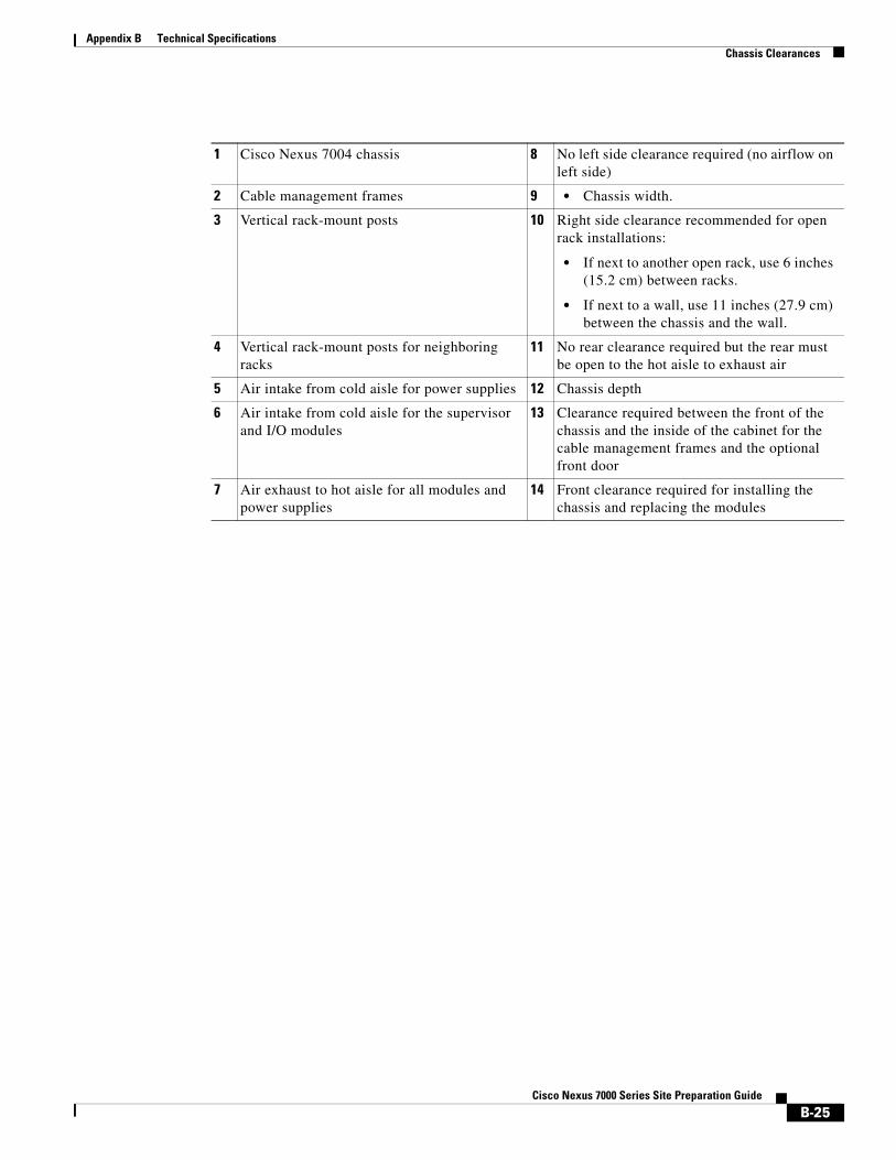
Appendix B Technical SpecificationsChassis Clearances
1 Cisco Nexus 7004 chassis 8 No left side clearance required (no airflow on left side)
2 Cable management frames 9 • Chassis width.
3 Vertical rack-mount posts 10 Right side clearance recommended for open rack installations:
• If next to another open rack, use 6 inches (15.2 cm) between racks.
• If next to a wall, use 11 inches (27.9 cm) between the chassis and the wall.
4 Vertical rack-mount posts for neighboring racks
11 No rear clearance required but the rear must be open to the hot aisle to exhaust air
5 Air intake from cold aisle for power supplies 12 Chassis depth
6 Air intake from cold aisle for the supervisor and I/O modules
13 Clearance required between the front of the chassis and the inside of the cabinet for the cable management frames and the optional front door
7 Air exhaust to hot aisle for all modules and power supplies
14 Front clearance required for installing the chassis and replacing the modules
B-25Cisco Nexus 7000 Series Site Preparation Guide
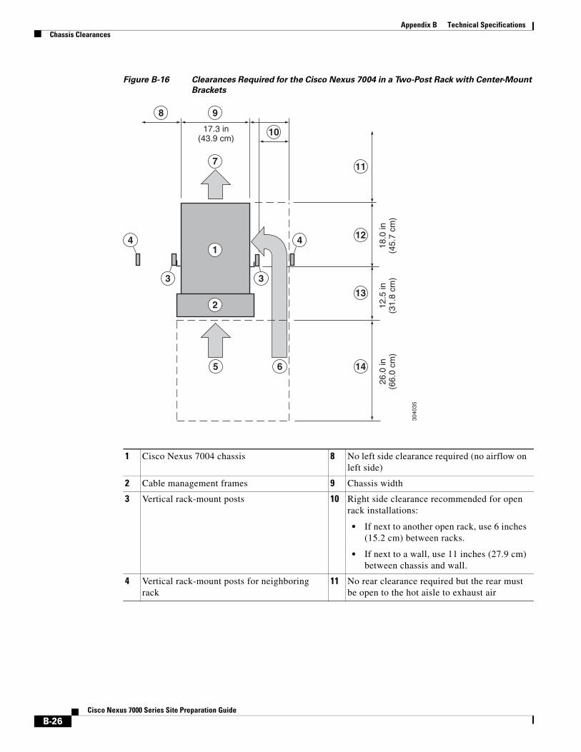
Appendix B Technical SpecificationsChassis Clearances
Figure B-16 Clearances Required for the Cisco Nexus 7004 in a Two-Post Rack with Center-Mount
Brackets
17.3 in(43.9 cm)
18.0
in(4
5.7
cm)
12.5
in(3
1.8
cm)
26.0
in(6
6.0
cm)
1
7
9
10
11
12
13
1465
8
2
3
4 4
3
3040
35
1 Cisco Nexus 7004 chassis 8 No left side clearance required (no airflow on left side)
2 Cable management frames 9 Chassis width
3 Vertical rack-mount posts 10 Right side clearance recommended for open rack installations:
• If next to another open rack, use 6 inches (15.2 cm) between racks.
• If next to a wall, use 11 inches (27.9 cm) between chassis and wall.
4 Vertical rack-mount posts for neighboring rack
11 No rear clearance required but the rear must be open to the hot aisle to exhaust air
B-26Cisco Nexus 7000 Series Site Preparation Guide
Appendix B Technical SpecificationsChassis Clearances
Cisco Nexus 7009 Chassis ClearancesThe Cisco Nexus 7009 chassis has different clearance requirements for installations with four-post racks or cabinets, two-post racks with front-mount brackets, and two-post racks with center-mount brackets.
For four-post rack or cabinet installations, the chassis requires the following clearances (see Figure B-17):
• Front clearance requires both of the following:
– Cabling area of 7.5 inches (19.1 cm) between the front of the chassis and the inside surface of the cabinet or rack (this area can include the optional cable management frames)
– Maintenance area of 24 inches (61.1 cm) between the front of the rack or cabinet and the next object in the cold aisle.
Note You might need to increase the maintenance area to accommodate a wide mechanical lift used to move the chassis to or from the rack.
• Rear clearance includes both of the following:
– Cabling area of 7 inches (17.8 cm) between the rear of the chassis and the inside surface of the cabinet or rack
– Maintenance area of 24 inches (61.1 cm) between the rear of the rack or cabinet and the next object in the hot aisle
• Side clearance of 11 inches (27.9 cm) for air flow on each side of the chassis.
5 Air intake from cold aisle for power supplies 12 Distance from front of vertical rack-mount posts to rear of chassis
6 Air intake from cold aisle for the supervisor and I/O modules
13 Clearance required between the front of the chassis and the inside of the chassis for the cable management frames and the optional front doors
7 Air exhaust to hot aisle for all modules and power supplies
14 Front service clearance required for installing the chassis and replacing the modules
B-27Cisco Nexus 7000 Series Site Preparation Guide
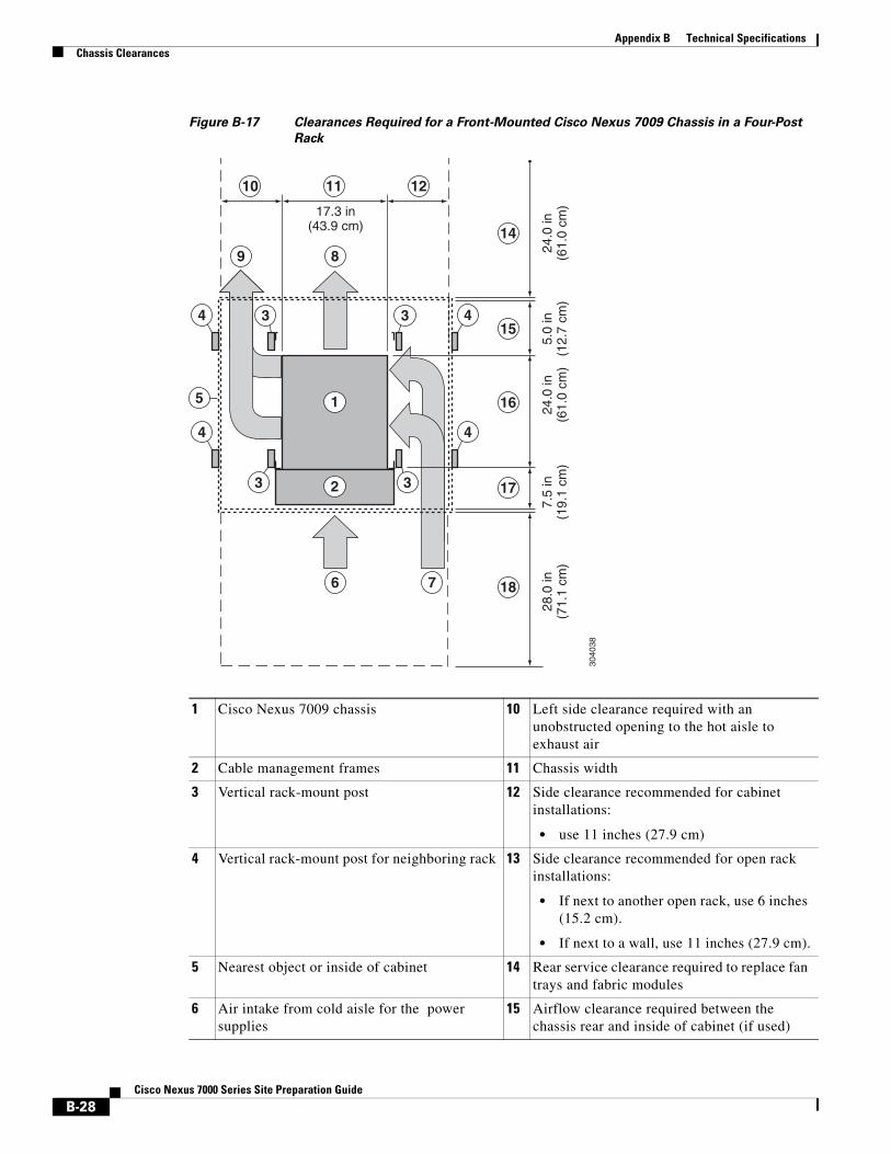
Appendix B Technical SpecificationsChassis Clearances
Figure B-17 Clearances Required for a Front-Mounted Cisco Nexus 7009 Chassis in a Four-Post
Rack
14
15
17
16
18
10 11 12
3040
38
89
5
3
3 3
3
17.3 in(43.9 cm)
24.0
in(6
1.0
cm)
7.5
in(1
9.1
cm)
24.0
in(6
1.0
cm)
28.0
in(7
1.1
cm)
6 7
1
2
5.0
in(1
2.7
cm)
4 4
4 4
1 Cisco Nexus 7009 chassis 10 Left side clearance required with an unobstructed opening to the hot aisle to exhaust air
2 Cable management frames 11 Chassis width
3 Vertical rack-mount post 12 Side clearance recommended for cabinet installations:
• use 11 inches (27.9 cm)
4 Vertical rack-mount post for neighboring rack 13 Side clearance recommended for open rack installations:
• If next to another open rack, use 6 inches (15.2 cm).
• If next to a wall, use 11 inches (27.9 cm).
5 Nearest object or inside of cabinet 14 Rear service clearance required to replace fan trays and fabric modules
6 Air intake from cold aisle for the power supplies
15 Airflow clearance required between the chassis rear and inside of cabinet (if used)
B-28Cisco Nexus 7000 Series Site Preparation Guide
Appendix B Technical SpecificationsChassis Clearances
For two-post rack installations with front-mount brackets, the chassis requires the following clearances (see Figure B-18):
• Front clearance requires both of the following:
– Cabling area of 7.5 inches (19.1 cm) between the front of the chassis and the cold aisle (this area can include the optional cable management frames)
– Maintenance area of 28 inches (71.1 cm) in front of the cabling area for installing the chassis and replacing modules
Note You might need to increase the maintenance area to accommodate a wide mechanical lift used to move the chassis to or from the rack.
• Rear clearance requires 26 inches (66.0 cm) behind the chassis for cable management and for replacing modules and power supplies
• Side clearance recommendation depends on whether you use a rack or cabinet for the installation as follows:
– For cabinet installations, we recommend that you use 11 inches (27.9 cm) for airflow on each side of the chassis.
– For rack installations, we recommend 11 inches (27.9 cm) between the chassis and a wall or 6 inches (15.2 cm) between racks.
7 Air intake from cold aisle for the supervisor, fabric, and I/O modules
16 Chassis depth
8 Air exhaust to hot aisle for power supplies 17 Clearance required between the front of the chassis and the inside of the cabinet (if used) or edge of cold aisle (if no cabinet) for the cable management frames and the optional front doors
9 Air exhaust to hot aisle for the supervisor, fabric, and I/O modules
18 Front clearance required for installing the chassis and replacing the modules
B-29Cisco Nexus 7000 Series Site Preparation Guide
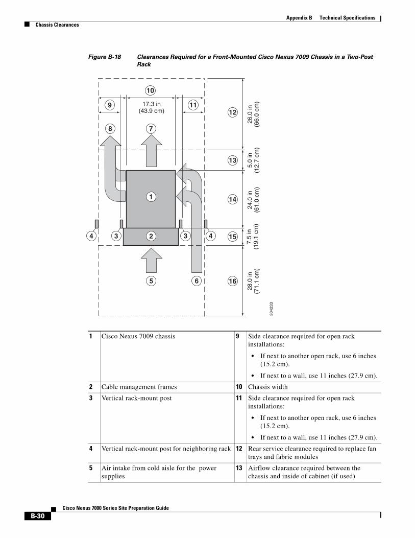
Appendix B Technical SpecificationsChassis Clearances
Figure B-18 Clearances Required for a Front-Mounted Cisco Nexus 7009 Chassis in a Two-Post
Rack
12
13
14
15
16
10
119
3042
33
8 7
65
34 3 4
17.3 in(43.9 cm)
7.5
in(1
9.1
cm)
24.0
in(6
1.0
cm)
26.0
in(6
6.0
cm)
28.0
in(7
1.1
cm)
5.0
in(1
2.7
cm)
1
2
1 Cisco Nexus 7009 chassis 9 Side clearance required for open rack installations:
• If next to another open rack, use 6 inches (15.2 cm).
• If next to a wall, use 11 inches (27.9 cm).
2 Cable management frames 10 Chassis width
3 Vertical rack-mount post 11 Side clearance required for open rack installations:
• If next to another open rack, use 6 inches (15.2 cm).
• If next to a wall, use 11 inches (27.9 cm).
4 Vertical rack-mount post for neighboring rack 12 Rear service clearance required to replace fan trays and fabric modules
5 Air intake from cold aisle for the power supplies
13 Airflow clearance required between the chassis and inside of cabinet (if used)
B-30Cisco Nexus 7000 Series Site Preparation Guide
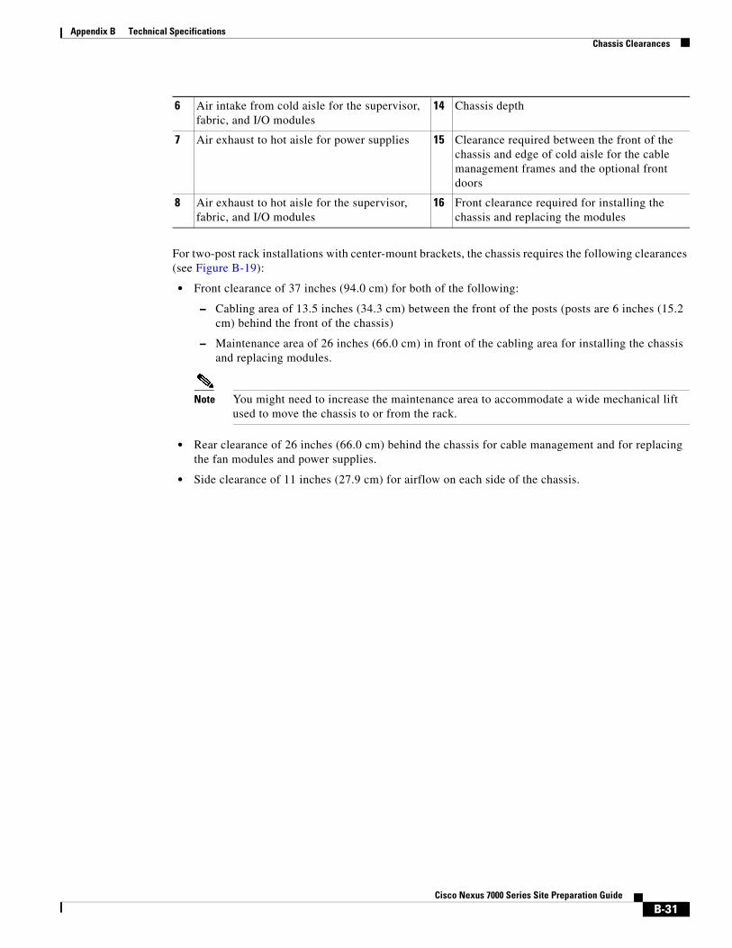
Appendix B Technical SpecificationsChassis Clearances
For two-post rack installations with center-mount brackets, the chassis requires the following clearances (see Figure B-19):
• Front clearance of 37 inches (94.0 cm) for both of the following:
– Cabling area of 13.5 inches (34.3 cm) between the front of the posts (posts are 6 inches (15.2 cm) behind the front of the chassis)
– Maintenance area of 26 inches (66.0 cm) in front of the cabling area for installing the chassis and replacing modules.
Note You might need to increase the maintenance area to accommodate a wide mechanical lift used to move the chassis to or from the rack.
• Rear clearance of 26 inches (66.0 cm) behind the chassis for cable management and for replacing the fan modules and power supplies.
• Side clearance of 11 inches (27.9 cm) for airflow on each side of the chassis.
6 Air intake from cold aisle for the supervisor, fabric, and I/O modules
14 Chassis depth
7 Air exhaust to hot aisle for power supplies 15 Clearance required between the front of the chassis and edge of cold aisle for the cable management frames and the optional front doors
8 Air exhaust to hot aisle for the supervisor, fabric, and I/O modules
16 Front clearance required for installing the chassis and replacing the modules
B-31Cisco Nexus 7000 Series Site Preparation Guide
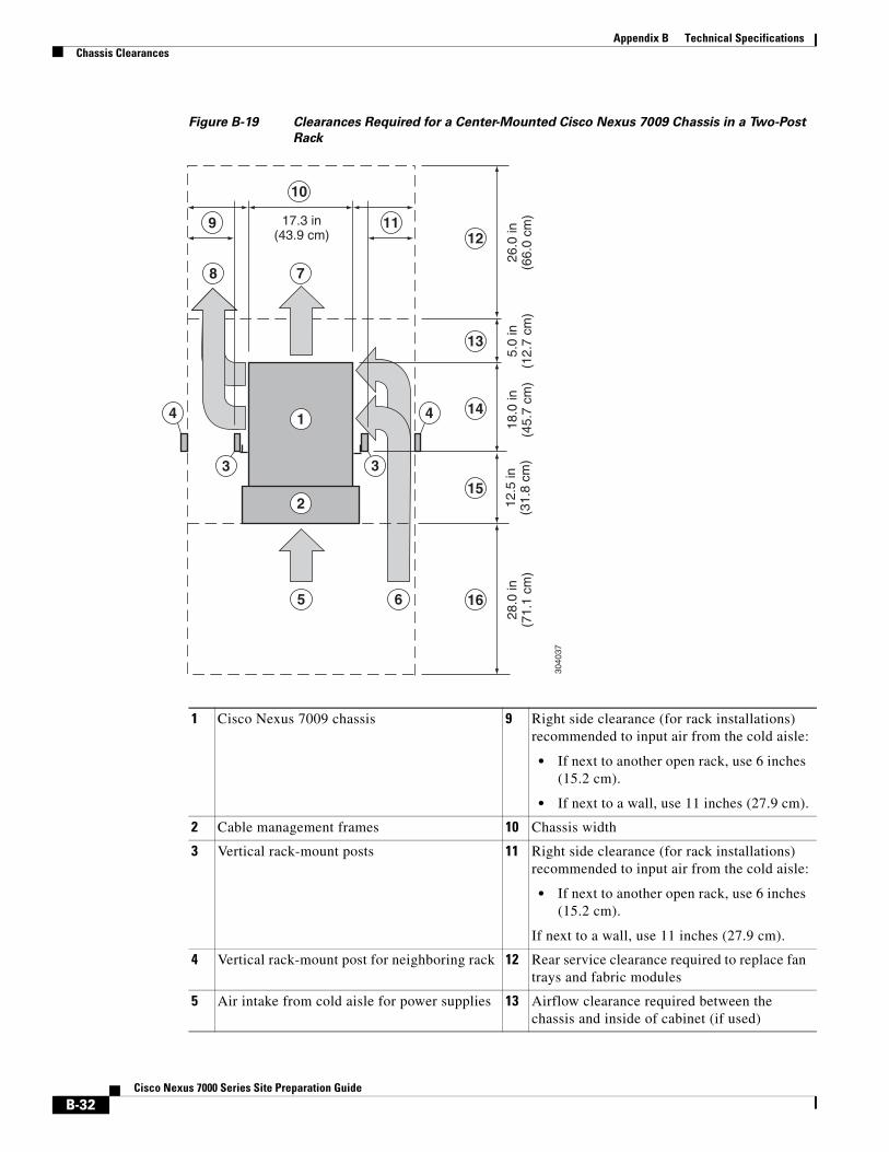
Appendix B Technical SpecificationsChassis Clearances
Figure B-19 Clearances Required for a Center-Mounted Cisco Nexus 7009 Chassis in a Two-Post
Rack
12
13
14
15
16
10
119
3040
37
8 7
65
3 3
17.3 in(43.9 cm)
12.5
in(3
1.8
cm)
18.0
in(4
5.7
cm)
26.0
in(6
6.0
cm)
28.0
in(7
1.1
cm)
5.0
in(1
2.7
cm)
1
2
4 4
1 Cisco Nexus 7009 chassis 9 Right side clearance (for rack installations) recommended to input air from the cold aisle:
• If next to another open rack, use 6 inches (15.2 cm).
• If next to a wall, use 11 inches (27.9 cm).
2 Cable management frames 10 Chassis width
3 Vertical rack-mount posts 11 Right side clearance (for rack installations) recommended to input air from the cold aisle:
• If next to another open rack, use 6 inches (15.2 cm).
If next to a wall, use 11 inches (27.9 cm).
4 Vertical rack-mount post for neighboring rack 12 Rear service clearance required to replace fan trays and fabric modules
5 Air intake from cold aisle for power supplies 13 Airflow clearance required between the chassis and inside of cabinet (if used)
B-32Cisco Nexus 7000 Series Site Preparation Guide

Appendix B Technical SpecificationsChassis Clearances
Cisco Nexus 7010 Chassis ClearancesThe Cisco Nexus 7010 chassis requires the following clearances (see Figure B-20):
• Front clearance of 45.5 inches (115.6 cm) for both of the following:
– Cabling area of 7.5 inches (19.1 cm) between the front of the chassis and the inside of the cabinet or front of the rack
– Maintenance area of 38 inches (96.5 cm) of cold-aisle passageway in front of the rack or cabinet
Note You might need to increase the maintenance area to accommodate a wide mechanical lift used to move the chassis to or from the rack.
• Rear clearance of 35 inches (88.9 cm) for both of the following:
– Airflow area of 5 inches (12.7 cm) inside of the cabinet or rack
– Maintenance area of 30 inches (76.2 cm) of hot-aisle passageway behind the rack or cabinet
6 Air intake from cold aisle for the supervisor, fabric, and I/O modules
14 Chassis depth
7 Air exhaust to hot aisle for the power supplies 15 Clearance required between the front of the chassis and the front of the cable management frames and the optional front doors
8 Air exhaust to hot aisle for the supervisor, fabric, and I/O modules
16 Front service clearance required for installing the chassis and replacing the modules
B-33Cisco Nexus 7000 Series Site Preparation Guide

Appendix B Technical SpecificationsChassis Clearances
Figure B-20 Clearances Required for the Cisco Nexus 7010 Switch
10
11
12
13
14
7 8
6
4
9
3040
39
17.3 in(43.9 cm)
33.1
in(8
4.1
cm)
7.5
in(1
9.1
cm)
38.0
in(9
6.5
cm)
30.0
in(7
6.2
cm)
5.0
in(1
2.7
cm)
1
2
5
3 3
3 3
1 Cisco Nexus 7010 chassis 8 Chassis width
2 Cable management system 9 No right side clearance required (no airflow on right side)
3 Vertical rack-mount posts 10 Rear service clearance required to replace fan trays and fabric modules
B-34Cisco Nexus 7000 Series Site Preparation Guide

Appendix B Technical SpecificationsChassis Clearances
Cisco Nexus 7018 Chassis ClearancesThe Cisco Nexus 7018 chassis requires the following clearances (see Figure B-21):
• Front clearance of 45 inches (114.3 cm) for both of the following:
– Cabling area of 7.5 inches (19.1 cm) between the front of the chassis and the inside of the cabinet or front of the rack
– Maintenance area of 38 inches (96.5 cm) between the front of the rack or cabinet and the next rack, cabinet, or wall in the cold aisle (additional area might be needed for a larger mechanical lift used to move the chassis)
• Rear clearance of 35 inches (88.9 cm) for both of the following:
– Airflow area of 5 inches (12.7 cm) inside a cabinet (if used)
– Maintenance area of 30 inches (76.2 cm) of hot-aisle passageway behind the rack or cabinet
• Side clearance recommendation depends on whether a cabinet or rack is used:
– For cabinet installations, use 11 inches (27.9 cm) between the chassis and inside of the cabinet.
– For rack installations, use either 11” (27.9 cm) between the chassis and a wall or 6” (15.2 cm) between racks.
4 Inside of cabinet (no side clearance required) 11 Airflow clearance required between the chassis and inside of cabinet (if used)
5 Air intake from cold aisle for all modules and power supplies
12 Chassis depth, which includes the fan tray handles at the rear of the chassis
6 Air exhaust to hot aisle for all modules and power supplies
13 Clearance required between the front of the chassis and the inside of the cabinet (if used) or edge of the cold aisle (if no cabinet) for the cable management frames and the optional front doors
7 No left side clearance required (no airflow on left side)
14 Front service clearance required for installing the chassis and replacing the modules
B-35Cisco Nexus 7000 Series Site Preparation Guide
Appendix B Technical SpecificationsChassis Clearances
Figure B-21 Clearances Required for the Cisco Nexus 7018 Switch
15
16
17
18
197
5
3040
40
17.3 in(43.9 cm)
33.1
in(8
4.1
cm)
7.5
in(1
9.1
cm)
38.0
in(9
6.5
cm)
30.0
in(7
6.2
cm)
5.0
in(1
2.7
cm)
1
2
6
3 3
34
4
4
4
3
89
11 12 13
10 14
B-36Cisco Nexus 7000 Series Site Preparation Guide
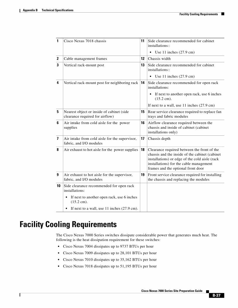
Appendix B Technical SpecificationsFacility Cooling Requirements
Facility Cooling RequirementsThe Cisco Nexus 7000 Series switches dissipate considerable power that generates much heat. The following is the heat dissipation requirement for these switches:
• Cisco Nexus 7004 dissipates up to 9737 BTUs per hour
• Cisco Nexus 7009 dissipates up to 28,101 BTUs per hour
• Cisco Nexus 7010 dissipates up to 35,162 BTUs per hour
• Cisco Nexus 7018 dissipates up to 51,195 BTUs per hour
1 Cisco Nexus 7018 chassis 11 Side clearance recommended for cabinet installations::
• Use 11 inches (27.9 cm)
2 Cable management frames 12 Chassis width
3 Vertical rack-mount post 13 Side clearance recommended for cabinet installations::
• Use 11 inches (27.9 cm)
4 Vertical rack-mount post for neighboring rack 14 Side clearance recommended for open rack installations:
• If next to another open rack, use 6 inches (15.2 cm).
If next to a wall, use 11 inches (27.9 cm)
5 Nearest object or inside of cabinet (side clearance required for airflow)
15 Rear service clearance required to replace fan trays and fabric modules
6 Air intake from cold aisle for the power supplies
16 Airflow clearance required between the chassis and inside of cabinet (cabinet installations only)
7 Air intake from cold aisle for the supervisor, fabric, and I/O modules
17 Chassis depth
8 Air exhaust to hot aisle for the power supplies 18 Clearance required between the front of the chassis and the inside of the cabinet (cabinet installations) or edge of the cold aisle (rack installations) for the cable management frames and the optional front door
9 Air exhaust to hot aisle for the supervisor, fabric, and I/O modules
19 Front service clearance required for installing the chassis and replacing the modules
10 Side clearance recommended for open rack installations:
• If next to another open rack, use 6 inches (15.2 cm).
• If next to a wall, use 11 inches (27.9 cm).
B-37Cisco Nexus 7000 Series Site Preparation Guide
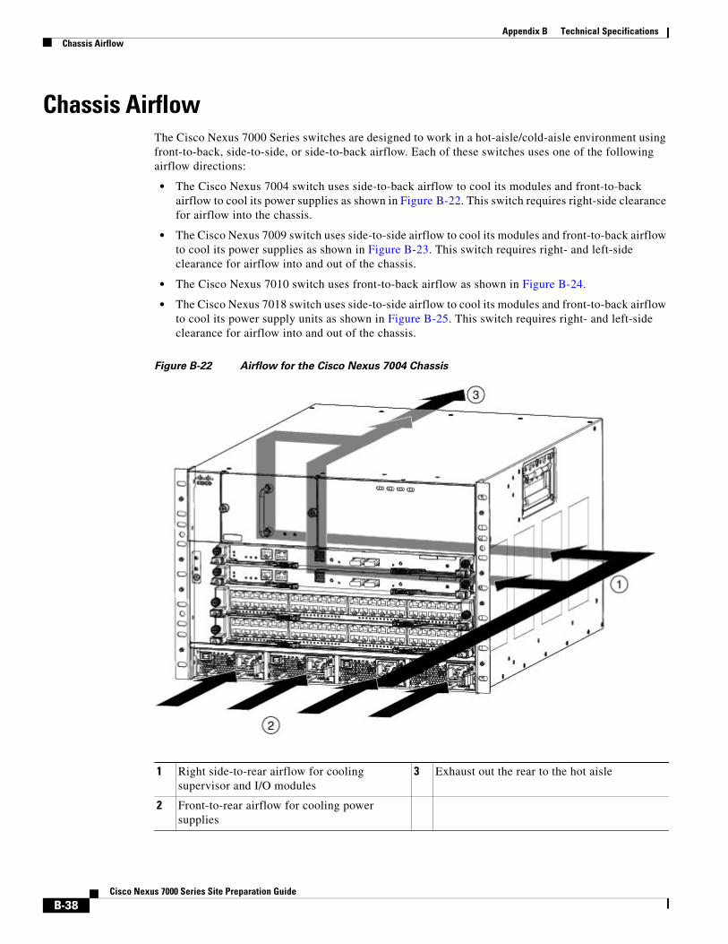
Appendix B Technical SpecificationsChassis Airflow
Chassis AirflowThe Cisco Nexus 7000 Series switches are designed to work in a hot-aisle/cold-aisle environment using front-to-back, side-to-side, or side-to-back airflow. Each of these switches uses one of the following airflow directions:
• The Cisco Nexus 7004 switch uses side-to-back airflow to cool its modules and front-to-back airflow to cool its power supplies as shown in Figure B-22. This switch requires right-side clearance for airflow into the chassis.
• The Cisco Nexus 7009 switch uses side-to-side airflow to cool its modules and front-to-back airflow to cool its power supplies as shown in Figure B-23. This switch requires right- and left-side clearance for airflow into and out of the chassis.
• The Cisco Nexus 7010 switch uses front-to-back airflow as shown in Figure B-24.
• The Cisco Nexus 7018 switch uses side-to-side airflow to cool its modules and front-to-back airflow to cool its power supply units as shown in Figure B-25. This switch requires right- and left-side clearance for airflow into and out of the chassis.
Figure B-22 Airflow for the Cisco Nexus 7004 Chassis
1 Right side-to-rear airflow for cooling supervisor and I/O modules
3 Exhaust out the rear to the hot aisle
2 Front-to-rear airflow for cooling power supplies
B-38Cisco Nexus 7000 Series Site Preparation Guide

Appendix B Technical SpecificationsChassis Airflow
Figure B-23 Airflow for the Cisco Nexus 7009 Chassis
1 Airflow for cooling the supervisor, I/O modules, and fabric modules
2 Airflow for cooling the power supply units
B-39Cisco Nexus 7000 Series Site Preparation Guide
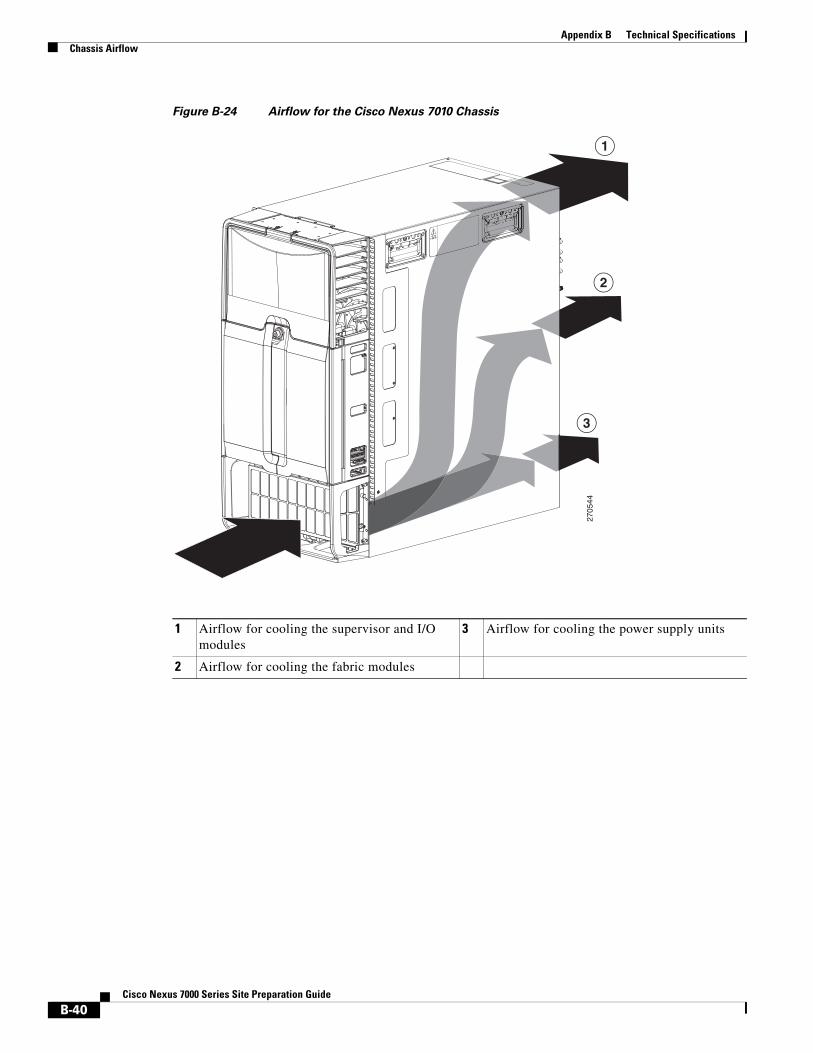
Appendix B Technical SpecificationsChassis Airflow
Figure B-24 Airflow for the Cisco Nexus 7010 Chassis
270544
2
3
1
1 Airflow for cooling the supervisor and I/O modules
3 Airflow for cooling the power supply units
2 Airflow for cooling the fabric modules
B-40Cisco Nexus 7000 Series Site Preparation Guide
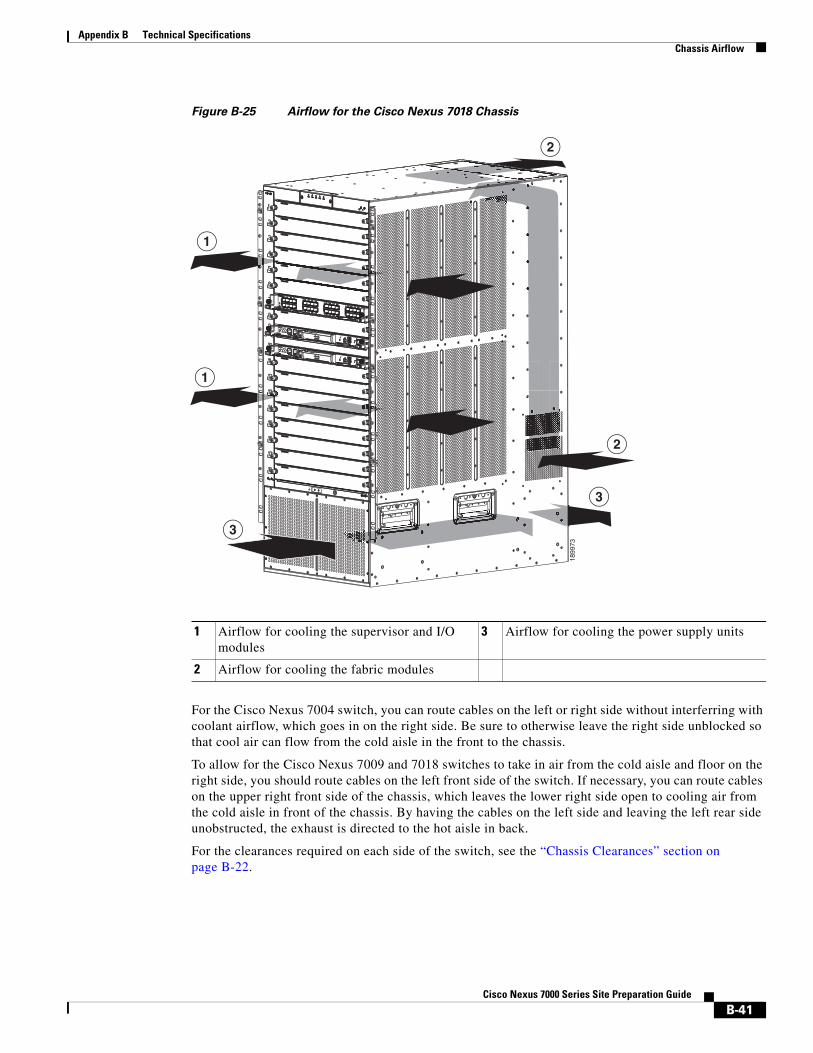
Appendix B Technical SpecificationsChassis Airflow
Figure B-25 Airflow for the Cisco Nexus 7018 Chassis
For the Cisco Nexus 7004 switch, you can route cables on the left or right side without interferring with coolant airflow, which goes in on the right side. Be sure to otherwise leave the right side unblocked so that cool air can flow from the cold aisle in the front to the chassis.
To allow for the Cisco Nexus 7009 and 7018 switches to take in air from the cold aisle and floor on the right side, you should route cables on the left front side of the switch. If necessary, you can route cables on the upper right front side of the chassis, which leaves the lower right side open to cooling air from the cold aisle in front of the chassis. By having the cables on the left side and leaving the left rear side unobstructed, the exhaust is directed to the hot aisle in back.
For the clearances required on each side of the switch, see the “Chassis Clearances” section on page B-22.
189973
1
1
2
2
3
3
1 Airflow for cooling the supervisor and I/O modules
3 Airflow for cooling the power supply units
2 Airflow for cooling the fabric modules
B-41Cisco Nexus 7000 Series Site Preparation Guide
Appendix B Technical SpecificationsChassis Airflow
B-42Cisco Nexus 7000 Series Site Preparation Guide

C-1Cisco Nexus 7000 Series Site Preparation Guide
A P P E N D I X CSite Preparation and Maintenance Records
This appendix provides a site planning list that you can use when preparing your site for the Cisco Nexus 7000 Series switches and includes these sections:
• Site Preparation Checklist, page C-1
• Contact and Site Information, page C-3
• Chassis and Module Information, page C-3
Site Preparation ChecklistPlanning the location and layout of your equipment rack or cabinet is essential for successful switch operation, ventilation, and accessibility.
Table C-1 lists the site planning tasks that we recommend that you complete before you install the Cisco Nexus 7000 Series switches. Your completion of each task ensures a successful switch installation.
Table C-1 Site Preparation Checklist
Planning Activity Verification Time and Date
Space evaluation:
• Space and layout
• Floor covering
• Impact and vibration
• Lighting
• Physical access
• Maintenance access
Environmental evaluation:
• Ambient temperature
• Humidity
• Altitude
• Atmospheric contamination
• Airflow

C-2Cisco Nexus 7000 Series Site Preparation Guide
Appendix C Site Preparation and Maintenance RecordsSite Preparation Checklist
Power evaluation:
• Input power type
• Power receptacles
• Receptacle proximity to the equipment
• Dedicated (separate) circuits for power redundancy
• UPS for power failures
• Grounding: proper gauge wire and lugs
• Circuit breaker size
Grounding evaluation:
• Data center ground
Cable and interface equipment evaluation:
• Cable type
• Connector type
• Cable distance limitations
• Interface equipment (transceivers)
EMI evaluation:
• Distance limitations for signaling
• Site wiring
• RFI levels
Table C-1 Site Preparation Checklist (continued)
Planning Activity Verification Time and Date
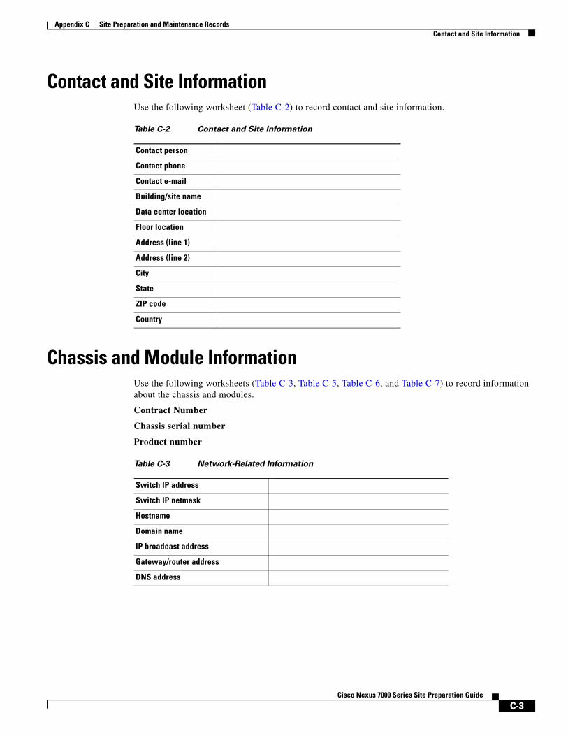
C-3Cisco Nexus 7000 Series Site Preparation Guide
Appendix C Site Preparation and Maintenance RecordsContact and Site Information
Contact and Site InformationUse the following worksheet (Table C-2) to record contact and site information.
Chassis and Module InformationUse the following worksheets (Table C-3, Table C-5, Table C-6, and Table C-7) to record information about the chassis and modules.
Contract Number
Chassis serial number
Product number
Table C-2 Contact and Site Information
Contact person
Contact phone
Contact e-mail
Building/site name
Data center location
Floor location
Address (line 1)
Address (line 2)
City
State
ZIP code
Country
Table C-3 Network-Related Information
Switch IP address
Switch IP netmask
Hostname
Domain name
IP broadcast address
Gateway/router address
DNS address
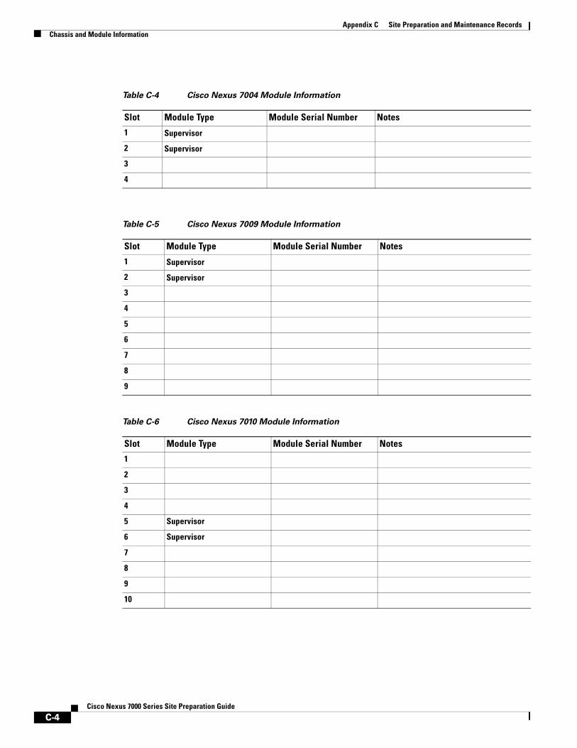
C-4Cisco Nexus 7000 Series Site Preparation Guide
Appendix C Site Preparation and Maintenance RecordsChassis and Module Information
Table C-4 Cisco Nexus 7004 Module Information
Slot Module Type Module Serial Number Notes
1 Supervisor
2 Supervisor
3
4
Table C-5 Cisco Nexus 7009 Module Information
Slot Module Type Module Serial Number Notes
1 Supervisor
2 Supervisor
3
4
5
6
7
8
9
Table C-6 Cisco Nexus 7010 Module Information
Slot Module Type Module Serial Number Notes
1
2
3
4
5 Supervisor
6 Supervisor
7
8
9
10

C-5Cisco Nexus 7000 Series Site Preparation Guide
Appendix C Site Preparation and Maintenance RecordsChassis and Module Information
Table C-7 Cisco Nexus 7018 Module Information
Slot Module Type Module Serial Number Notes
1
2
3
4
5
6
7
8
9 Supervisor
10 Supervisor
11
12
13
14
15
16
17
18

C-6Cisco Nexus 7000 Series Site Preparation Guide
Appendix C Site Preparation and Maintenance RecordsChassis and Module Information