citation m constactor - bch india-switchgear manufacturers...
TRANSCRIPT
CITATION M CONTACTOR
BCH Citation 'M' Contactors have been designed keeping in view high performance parameters and easy maintenance. These are suitable for mill duty, crane control, motor control centres, switching of solenoids, capacitor banks and for lighting & heating circuits.
Citation M Contactor
Coil
Encapsulated coil is moisture and heat resistant. It can with-stand wide variation in atmospheric conditions. The dual winding type design gives smoother pull, less impact on closure and minimum contact bounce giving trouble-free life.
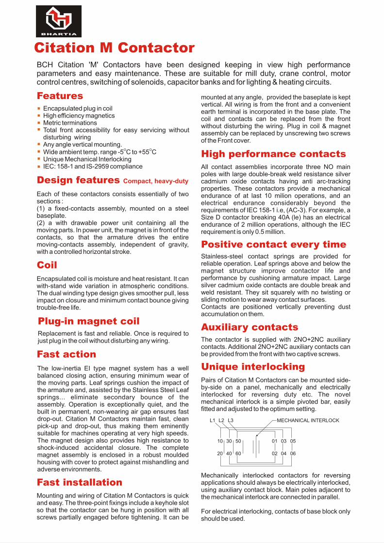
Mechanically interlocked contactors for reversing applications should always be electrically interlocked, using auxiliary contact block. Main poles adjacent to the mechanical interlock are connected in parallel.
For electrical interlocking, contacts of base block only should be used.
mounted at any angle, provided the baseplate is kept vertical. All wiring is from the front and a convenient earth terminal is incorporated in the base plate. The coil and contacts can be replaced from the front without disturbing the wiring. Plug in coil & magnet assembly can be replaced by unscrewing two screws of the Front cover.
All contact assemblies incorporate three NO main poles with large double-break weld resistance silver cadmium oxide contacts having anti arc-tracking properties. These contactors provide a mechanical endurance of at last 10 milion operations, and an electrical endurance considerably beyond the requirements of IEC 158-1 i.e, (AC-3). For example, a Size D contactor breaking 40A (le) has an electrical endurance of 2 million operations, although the IEC requirement is only 0.5 million.
Design features Compact, heavy-duty
High performance contacts
Each of these contactors consists essentially of two sections :(1) a fixed-contacts assembly, mounted on a steel baseplate. (2) a with drawable power unit containing all the moving parts. In power unit, the magnet is in front of the contacts, so that the armature drives the entire moving-contacts assembly, independent of gravity, with a controlled horizontal stroke.
Plug-in magnet coilReplacement is fast and reliable. Once is required to just plug in the coil without disturbing any wiring.
Fast action
The low-inertia EI type magnet system has a well balanced closing action, ensuring minimum wear of the moving parts. Leaf springs cushion the impact of the armature and, assisted by the Stainless Steel Leaf springs... eliminate secondary bounce of the assembly. Operation is exceptionally quiet, and the built in permanent, non-wearing air gap ensures fast drop-out. Citation M Contactors maintain fast, clean pick-up and drop-out, thus making them eminently suitable for machines operating at very high speeds. The magnet design also provides high resistance to shock-induced accidental closure. The complete magnet assembly is enclosed in a robust moulded housing with cover to protect against mishandling and adverse environments.
Fast installation
Mounting and wiring of Citation M Contactors is quick and easy. The three-point fixings include a keyhole slot so that the contactor can be hung in position with all screws partially engaged before tightening. It can be
Stainless-steel contact springs are provided for reliable operation. Leaf springs above and below the magnet structure improve contactor life and performance by cushioning armature impact. Large silver cadmium oxide contacts are double break and weld resistant. They sit squarely with no twisting or sliding motion to wear away contact surfaces.Contacts are positioned vertically preventing dust accumulation on them.
Positive contact every time
The contactor is supplied with 2NO+2NC auxiliary contacts. Additional 2NO+2NC auxiliary contacts can be provided from the front with two captive screws.
Auxiliary contacts
Pairs of Citation M Contactors can be mounted side-by-side on a panel, mechanically and electrically interlocked for reversing duty etc. The novel mechanical interlock is a simple pivoted bar, easily fitted and adjusted to the optimum setting.
Unique interlocking
MECHANICAL INTERLOCK
10 30 50 01 03 05
20 40 60 02 04 06
L1 L2 L3
FeaturesEncapsulated plug in coilHigh efficiency magneticsMetric terminationsTotal front accessibility for easy servicing without disturbing wiringAny angle vertical mounting.
O OWide ambient temp. range -5 C to +55 CUnique Mechanical InterlockingIEC: 158-1 and IS-2959 compliance
AUXILIARY CONTACT BLOCKCODE
Contactor size C4 & D E
Base block 1NO + 1NC MC 320 KB2 AC 35 EB11
Add-on-block 1 NO + 1 NC AC 34 EA11 AC 34 EA11
Mechanical interlock MC 321 KM1 MC 321 KM2
RATED MODE OF L/R RATIO DC2 TO DC5VOLTAGE CONNECTION RATINGS.
Contactor SizeC4 D E
125V 3 poles in series 15m secs. 20A 25A 40A
250V 3 poles in series 15m secs. 16A 20A 40A
DC ratings of main contacts
Encapsulated double-bobbin coils are suitables for a wide range of standard AC voltages. The class B and class F insulation of these coils, with its high thermal capacity, provides long life under both normal and adverse conditions. Coil power requirements are low, placing less load on pilot circuits and reducing transformer size when a number of contactors are controlled by a single transformer.
Lower power consumption
The power unit containing coil, magnet, armature and moving contacts can be removed in seconds by simply loosening two screws. Thus, maintenance does not involve disturbing wiring or removing the contactor from the panel. All contacts are clearly visible when the power unit is removed, and all dismantling screws are captive. For replacement, moving contacts merely slide out of their holders, while each fixed contact is served by just one or two screws.
Easy maintenance–anywhere
ACI rating : 1200/hrAC2 and AC3 rating : 750/hrAC4 rating : 250/hr
AC3 and AC4 ratings given under making and breaking capacities are maximum ratings but achieved at the expense of reduced electrical life.
Rotor Contactors, Intermediate ratings apply only when they are subsequently short circuited by the final rotor contactor. For regulating duty, the final ratings should be used. The contactors must not make and break on more than 700 volts.
Star-Delta, Phase connected. Star and delta contactors should be mechanically and electrically interlocked. The ratings for star and delta contactors are identical since mechanical interlocking is possible only between contactors of the same size. e.g. Contactors C4 & D.
Maximum number of
operations
Terminal plate with belting hole
AUX. MAIN SCREW CABLECONTACTOR TERMINALS AND Sq. mm.SIZE SADDLE CLAMP
CA 1 or 2 Cables M5 16D of 4 mm2 M5 16E Captive clamp M8 35
with Screw M4
Termination
CATALOGUE CODE SIZE CODE
Contactor basic code C4 C4NE22
D MC10DN22
E MC10EN22
Auxiliary contacts 2NO + 2NC are supplied with all Contactors
Voltage code (50Hz)110 V A220 V B240 V K415 V M
A 32 Amp open contactor with 110V 50 Hz coil fitted with 2 NO + 2NC auxiliary contacts is termed as C4NE22A.
Accessories
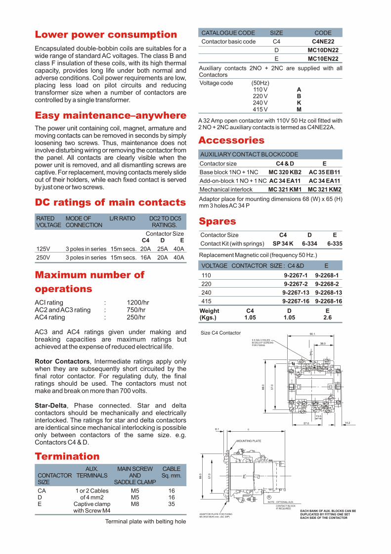
Adaptor place for mounting dimensions 68 (W) x 65 (H) mm 3 holes AC 34 P
Spares
Contactor Size C4 D E
Contact Kit (with springs) SP 34 K 6-334 6-335
Replacement Magnetic coil (frequency 50 Hz.)
VOLTAGE CONTACTOR SIZE : C4 &D E
110 9-2267-1 9-2268-1
220 9-2267-2 9-2268-2
240 9-2267-13 9-2268-13
415 9-2267-16 9-2268-16
Weight C4 D E(Kgs.) 1.05 1.05 2.6
88
.0
57
.0
ADAPTOR PLATE FOR FIXING68 (W)X 65(H) mm. (AC 34P)
EACH BANK OF AUX. BLOCKS CAN BEDUPLICATED BY FITTING ONE SETEACH SIDE OF THE CONTACTOR
CONTACT BLOCKIF REQUIRED
NOTE : OPTIONAL AUX.
B
c6.1
MOUNTING PLATE
Size C4 Contactor 90.1
88.0
57.0
5.5 DIA.3 HOLESM 5X0.8 P SCREWSFOR FIXING
38.0
57.0
13.0
14.2
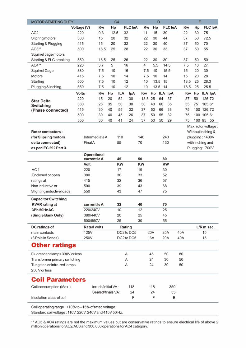
Max. rotor voltage :
Rotor contactors : Without inching &
(for Slipring motors Intermediate A 110 140 240 plugging : 1400V
delta connected) Final A 55 70 130 with inching and
as per IEC 292 Part 3 Plugging : 700V.
Volts Kw Hp ILA lpA Kw Hp ILA lpA Kw Hp ILA IpA
220 15 20 52 30 18.5 25 64 37 37 50 126 72
380 26 35 50 30 30 40 60 35 55 75 105 61
415 30 40 55 32 37 50 66 38 75 100 126 72
500 30 40 45 26 37 50 55 32 75 100 105 61
550 30 40 41 24 37 50 50 29 75 100 95 55
Star DeltaSwitching(Phase connected)
Capacitor Switching
KVAR rating at current le A 32 40 70
3Ph 50Hz AC 220/240V 10 12 25
(Single Bank Only) 380/440V 20 25 45
500/550V 25 30 55
DC ratings of Rated volts Rating L/R m.sec.
main contacts 125V DC2 to DC5 20A 25A 40A 15
(3 Pole in Series) 250V DC2 to DC5 16A 20A 40A 15
Other ratings
Fluorescent lamps 330V or less A 45 50 80
Transformer primary switching A 24 30 50
Tungsten or infra-red lamps A 24 30 50
250 V or less
Coil ParametersCoil consumption (Max.) inrush/initial VA : 118 118 350
Sealed/finals VA : 24 24 55
Insulation class of coil F F B
Coil operating range : +10% to –15% of rated voltage.
Standard coil voltage : 110V, 220V, 240V and 415V 50 Hz.
** AC3 & AC4 ratings are not the maximum values but are conservative ratings to ensure electrical life of above 2 million operations for AC2/AC3 and 300,000 operations for AC4 category.
Operationalcurrent le A 45 50 80
Volt KW KW KW
AC 1 220 17 19 30
Enclosed or open 380 30 33 52
ratings at 415 32 36 57
Non inductive or 500 39 43 68
Slighting inductive loads 550 43 47 75
MOTOR STARTING DUTY C4 D E
Voltage (V) Kw Hp FLC leA Kw Hp FLC leA Kw Hp FLC leA
AC2 220 9.3 12.5 32 11 15 39 22 30 75
Slipring motors 380 15 20 32 22 30 44 37 50 72.5
Starting & Plugging 415 15 20 32 22 30 40 37 50 70
AC3** 500 18.5 25 28 22 30 33 37 50 55
Squirrel cage motors
Starting & FLC breaking 550 18.5 25 26 22 30 30 37 50 50
AC4** 220 3.7 5 16 4 5.5 14.5 7.5 10 27
Squirrel Cage 380 7.5 10 16 7.5 10 15.5 15 20 30
Motors 415 7.5 10 14 7.5 10 14 15 20 28
Starting 500 7.5 10 12 10 13.5 15 18.5 25 28.3
Plugging & inching 550 7.5 10 12 10 13.5 14 18.5 25 25.5
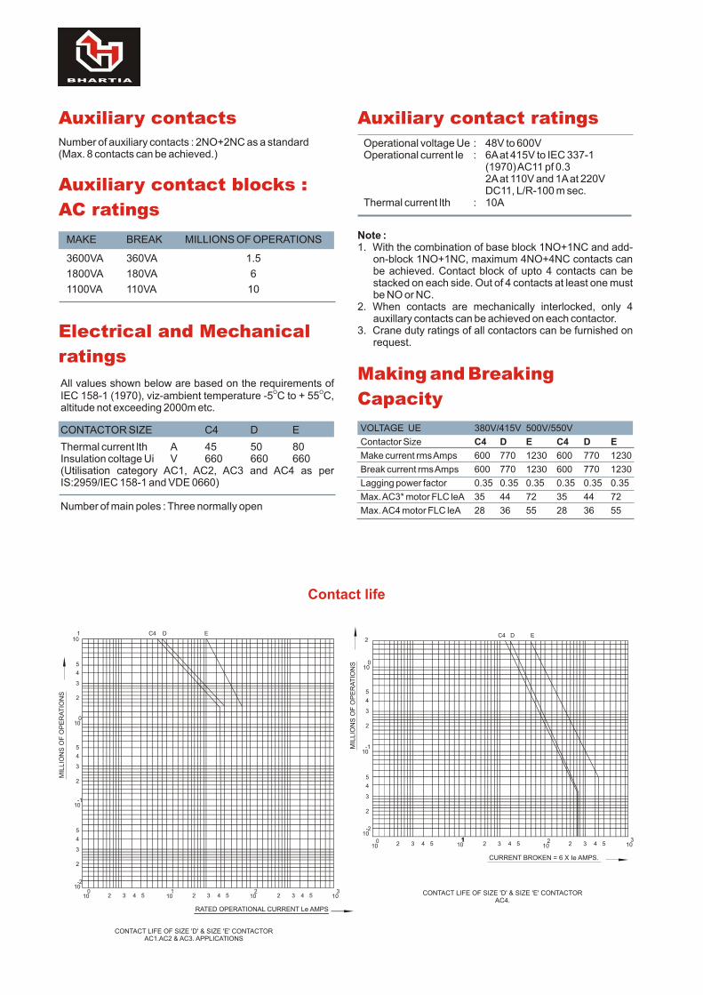
Auxiliary contactsNumber of auxiliary contacts : 2NO+2NC as a standard(Max. 8 contacts can be achieved.)
Auxiliary contact blocks :
AC ratings
MAKE BREAK MILLIONS OF OPERATIONS
3600VA 360VA 1.5
1800VA 180VA 6
1100VA 110VA 10
Auxiliary contact ratings
Operational voltage Ue : 48V to 600VOperational current le : 6A at 415V to IEC 337-1
(1970) AC11 pf 0.32A at 110V and 1A at 220VDC11, L/R-100 m sec.
Thermal current lth : 10A
Note :1. With the combination of base block 1NO+1NC and add-
on-block 1NO+1NC, maximum 4NO+4NC contacts can be achieved. Contact block of upto 4 contacts can be stacked on each side. Out of 4 contacts at least one must be NO or NC.
2. When contacts are mechanically interlocked, only 4 auxillary contacts can be achieved on each contactor.
3. Crane duty ratings of all contactors can be furnished on request.
Making and Breaking
Capacity
VOLTAGE UE 380V/415V 500V/550V
Contactor Size C4 D E C4 D E
Make current rms Amps 600 770 1230 600 770 1230
Break current rms Amps 600 770 1230 600 770 1230
Lagging power factor 0.35 0.35 0.35 0.35 0.35 0.35
Max. AC3* motor FLC leA 35 44 72 35 44 72
Max. AC4 motor FLC leA 28 36 55 28 36 55
Electrical and Mechanical
ratings
All values shown below are based on the requirements of O OIEC 158-1 (1970), viz-ambient temperature -5 C to + 55 C,
altitude not exceeding 2000m etc.
CONTACTOR SIZE C4 D E
Thermal current lth A 45 50 80Insulation coltage Ui V 660 660 660(Utilisation category AC1, AC2, AC3 and AC4 as per IS:2959/IEC 158-1 and VDE 0660)
Number of main poles : Three normally open

MC
P / C
MC
/ 3
00
0 / M
AY
05
Dimensions (mm)SIZE 'E' CONTACTOR
140.00 MAR
NOTE:-
OPTIONAL AUX. CONTACT BLOCK
IF REQUIRED.
C
TWO SETS OF MOUNTING HOLES ARE PROVIDED133/130 X 100MM (HOLES X) AND 138 X 37MM (HOLES Y)
0FOR HOLES Y, ROTATE THE CONTACTOR BY 100
HOLES X&Y DIA 6.20/6.5
100.0
EQ.EQ.
A 57.02 FIX NGS
6.456.20
170
.0
A
15
1.0
13
8.0
13
3.0
EARTHING POINT MO TAPPED
0.45,0.20DIA. 3FIXING HOLESFOR M6 SCREWS
A
SIZE 'D' CONTACTOR
90.1
45.6
6.45
6.20
DIA. 3 FIXING HOLESFOR M6 SCREWS
X&Y HOLES DIA 6.30/6.45
M-2
YX
YX
68.0
50.80
6.0 A
6.456.20
2 FIXINGS
65.0
Y
X
+
A
11.3
110.0
12
9.0
MA
X.
EAATHING POINTMS TAPPED.
E A C H B A N K O F A U X . B L O C K S C A N B E D U P L I C AT E D B Y F I T T I N G O N E S E T E A C HS I D E O F T H E C O N T R A C T O R .
TWO SETS OR MOUNTING HOLES ARE PROVIDED110.0X50.0MM (HOLES X) AND 65.0 X 63 MM (HOLES Y)
0 FOR HOLES Y, ROTATE THE CONTRACTOR BY 100 AND R E M O V E A U X I L I A R Y C O N TA C T B L O C K SFOR ACCESSIBILITY TO THE MOUNTING HOLES SHOWNDOTTED IN THE DIAGRAM.
'C'
D
NOTE :-
OPTIONAL AUX. CONTACT BLOCK
IF REQUIRED
RP./5
00
0/J
AN
.’08
Western UP & Uttarakhand8, Cooperative Industrial EstatePatel NagarDehradun : 248001UttarakhandMobile : 9760005793E-mail : [email protected]
Surat601/A, Ring RoadSurat - 395 002Mobile : 91 9825607617E-mail : [email protected]
21st Century Business CentreVadodara101, Toran Complex,Vikas NagarOld Padra RoadVadodara - 390 020.Tel. : 0265-6548444E-mail : [email protected]
ChennaiLVR CENTRE, 3rd FloorNo. 7, Seshadri Road,Alwarpet, Chennai - 600 018Tel. : 044-24997042, 24997002Mobile : 98402-85500Fax : 044-24996853E-mail : [email protected]
Salem 98433-19533