citroen ds repair manual 814 vol 1 march 1974
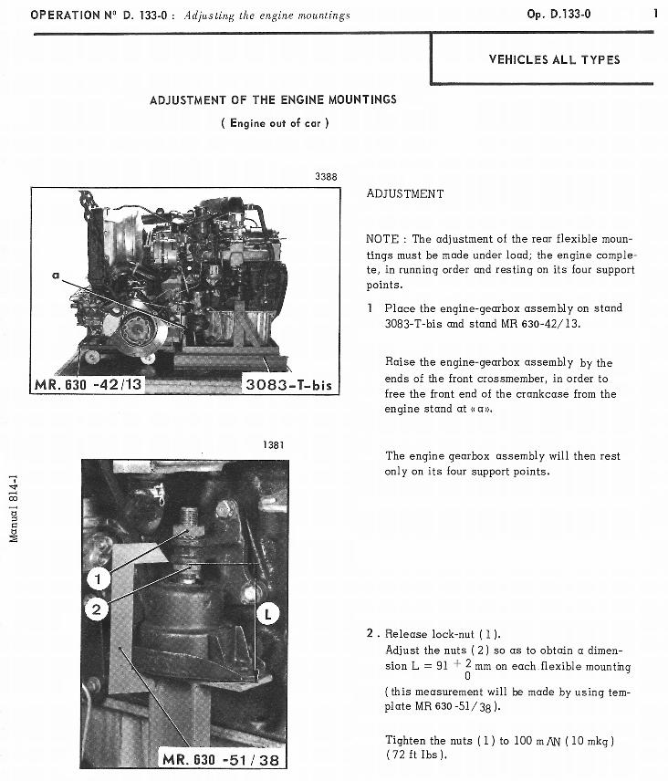
DESCRIPTION
Part oneTRANSCRIPT
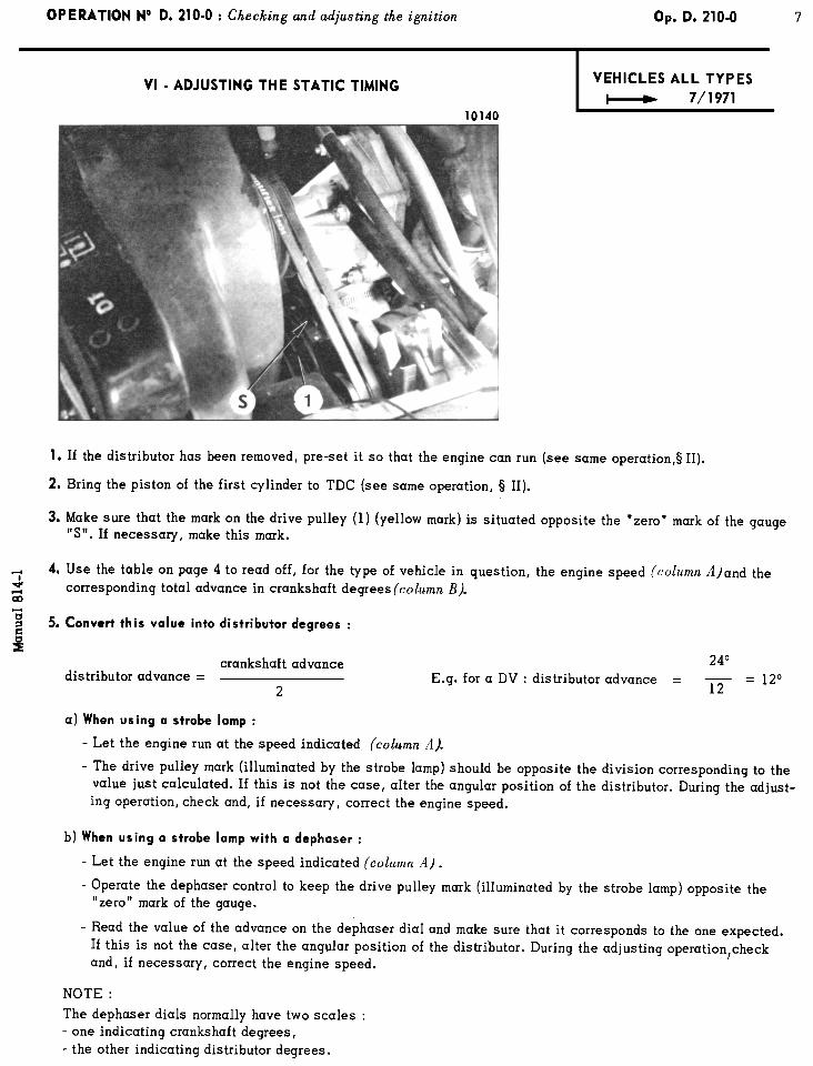
USING THE MANUAL
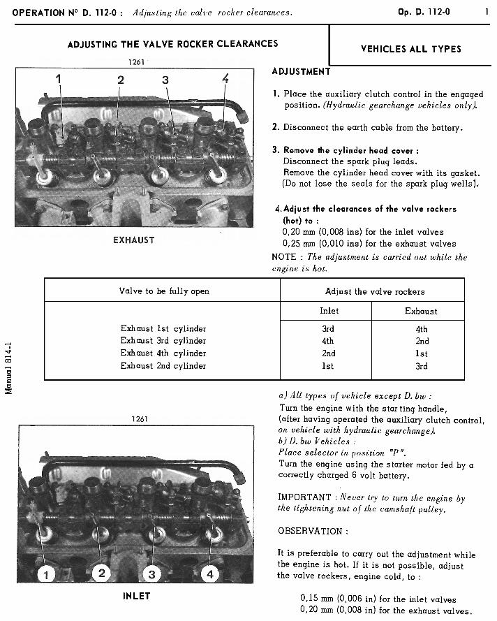
PRESENTATION
To facilitate the use of the Manual we have arranged the repair operations into two
volumes :
- Volume 1 contains :
- the CHARACTERISTICS - ADJUSTMENTS - CHECKS necessary at all repair work- shops for adjustment or simple repairs.
- Volume II contains the operations of:
- DISMANTLING and ASSEMBLING.
- RECONDITIONING.
- ELECTRICAL SYSTEM - HEATING - AIR CONDITIONING.
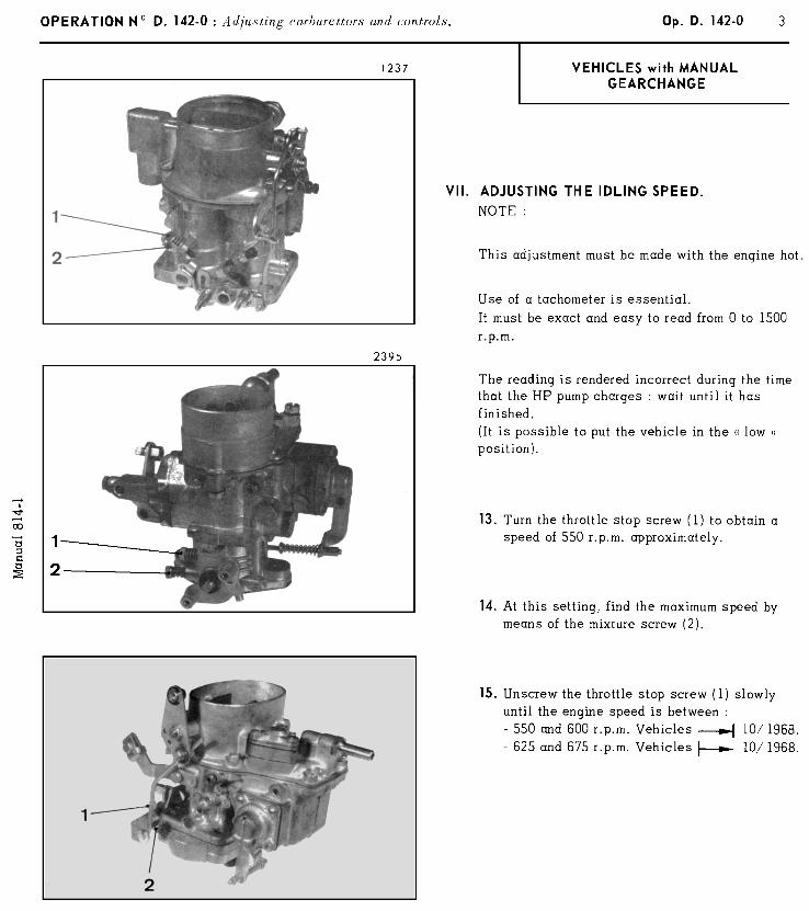
- BODYWORK.
Each volume is sold separately and it is presented in a red Fibrex with a ” MULTO ”type clasp to facilitate adding amendments or taking out an operation needed by the repairworkshop.
COMPOSITION
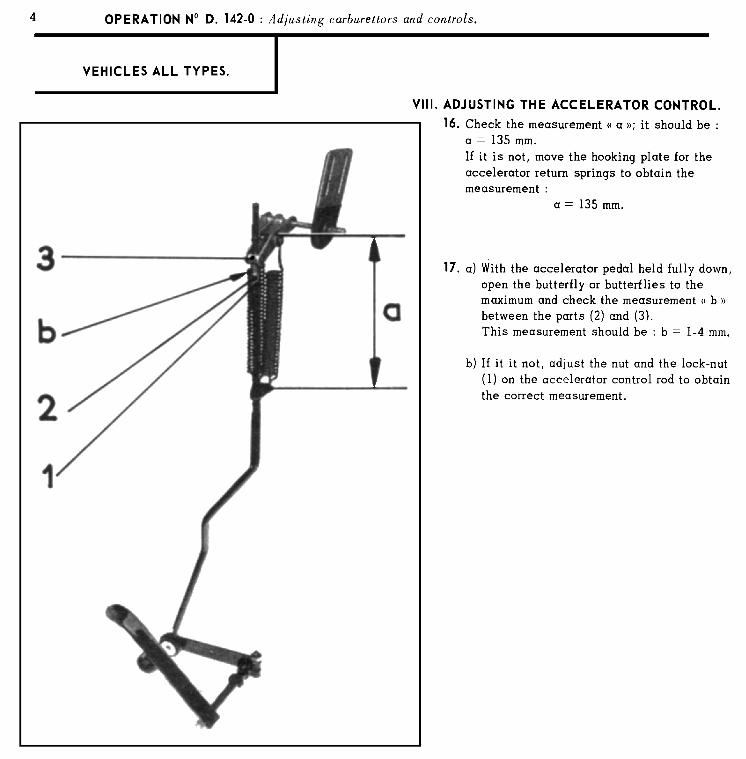
Each volume contains :
- a list of the operations appearing in the volume.
- the operations arranged in numerical order
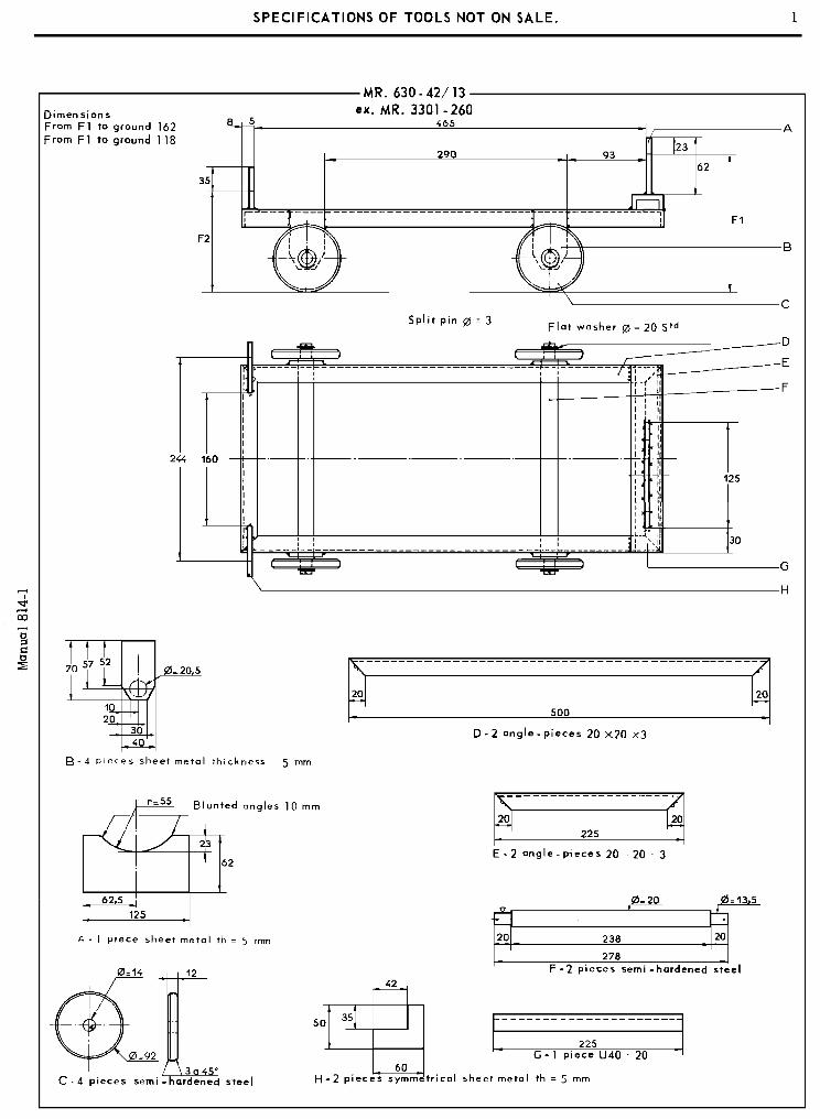
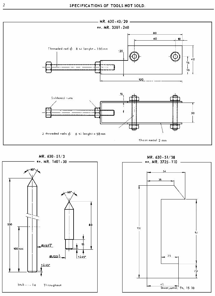
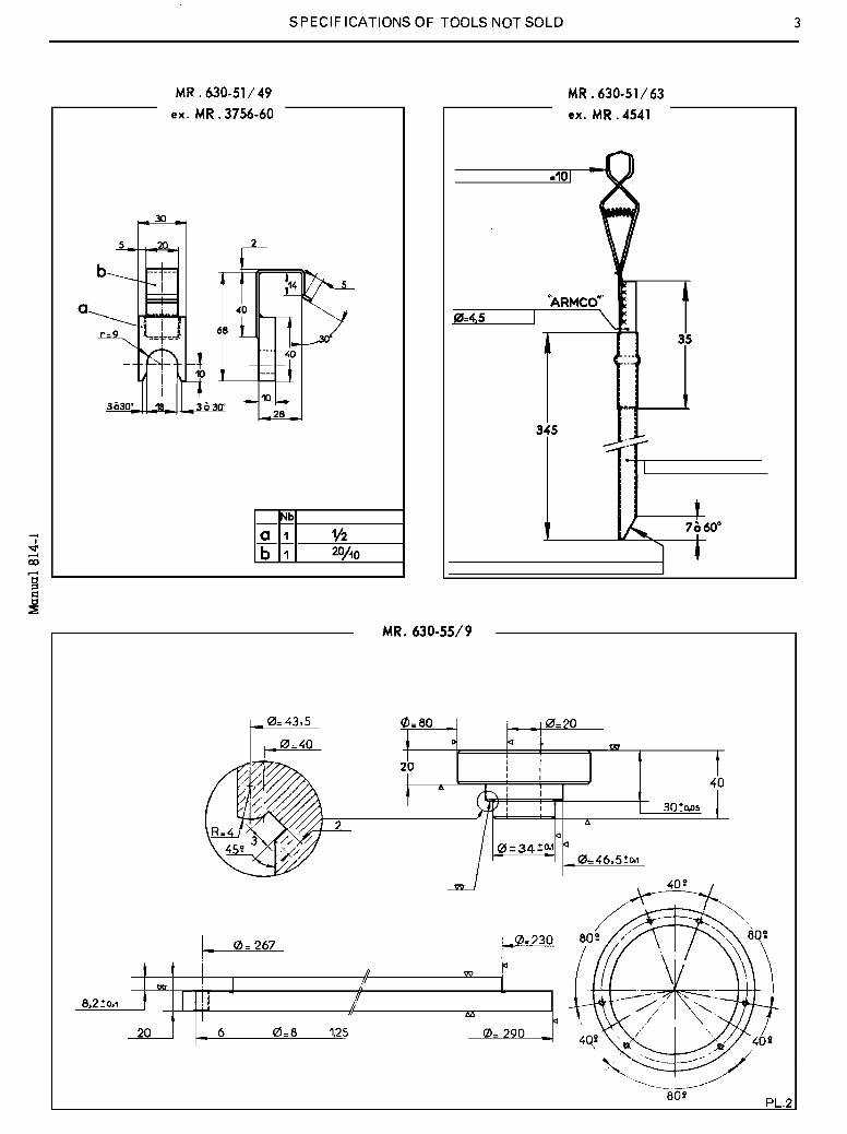
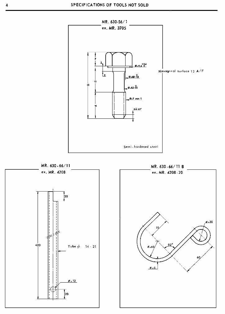
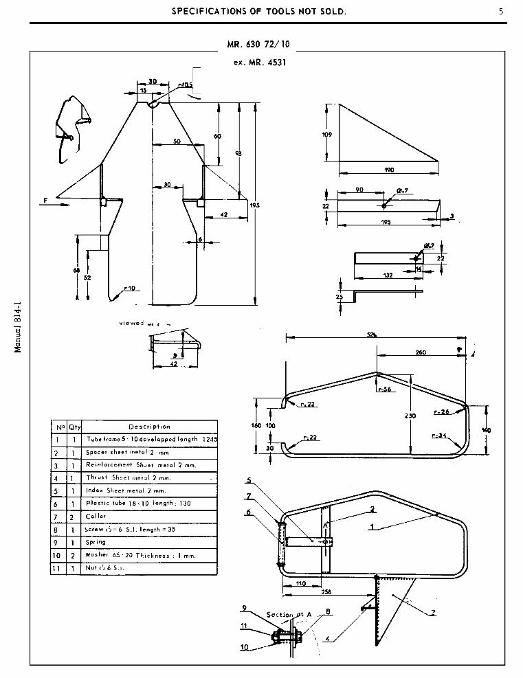
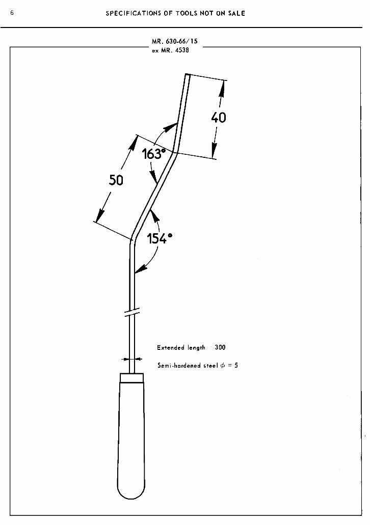
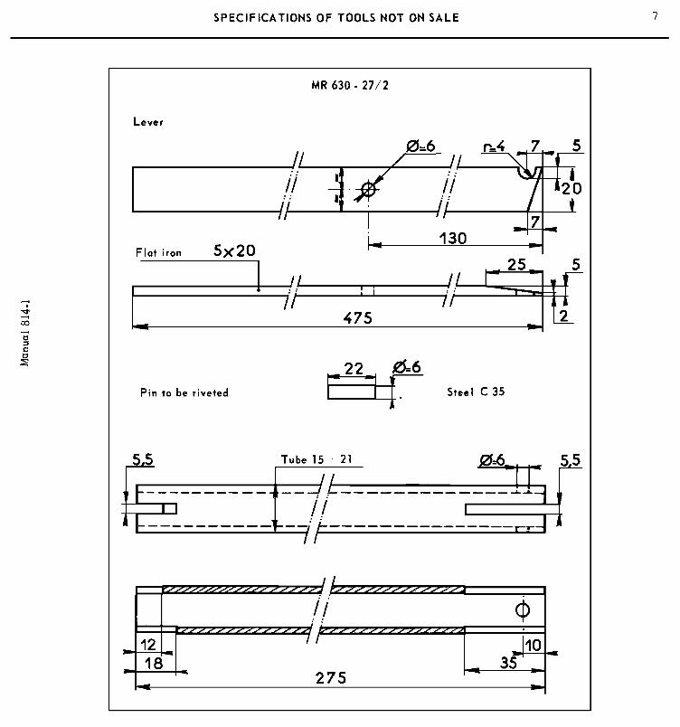
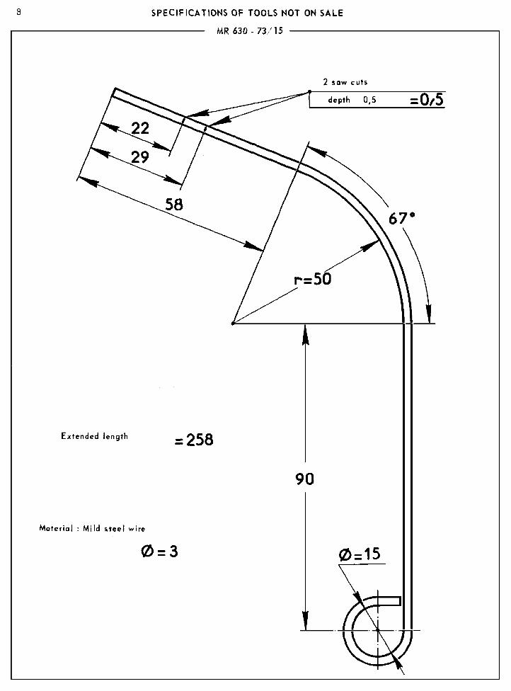
- a list of all the tools mentioned in the operations and drawings for making the specialtools that are not sold but that can be made by the repairer himself.
OPERATIONS
The operation sequence has been compiled to ensure the best quality of work in theshortest possible time,
The numbers of the operations are composed of :
a) letters indicating the vehicle :
- “D” concerns operations on D of all types (DTT)
- “D h” concerns operations on vehicles equipped with hylaudric gear-change
- “D m” concerns operations on vehicles equipped with a manual gear-change
- “DbW” concerns operations on vehicles equipped with automatic gear-change (DBW)
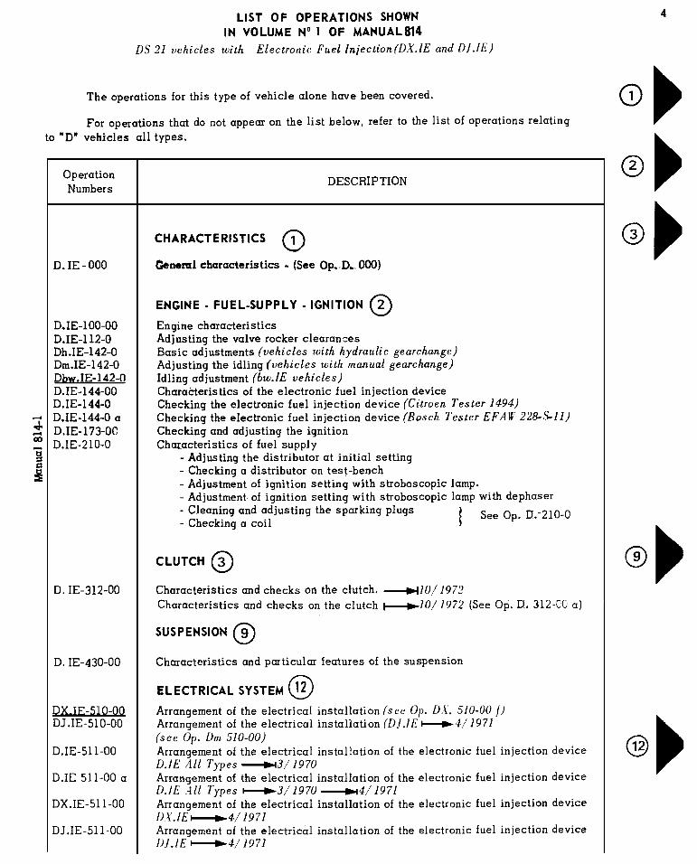
- “D.I.E.” concerns operations on vehicles equipped with Electronic Fuel Injection
(D.I.E. -operations are printed on pink paper).
- “DX” “DY” “DV” “DT”, etc... concern operations on these types of vehicles only.
b) a number with three figures indicating the unit or unit component.
c) a figure indicating the nature of the section.- figures 0 0 0 indicate the characteristics of the vehicle- figures 0 0 indicate the characteristics of the unit- figure 0 indicate checks and adjustment- figures 1 4 7 indicate the removal and fitting- figures 2 5 8 indicate stripping down and reassembly- figures 3 6 9 indicate reconditioningThe arrows corresponding to the operation list marks allow the required operation to be
found quickly.
TOOLS
Special tools are indicated in the text by a number followed by the letter T.These tools are sold by :- Etablissements FENWICK Department AMA 24 Bd. Biron - 93404 St Ouen FRANCEAdditional tools are indicated in the text by a number preceded by the letters MR.The drawings for making these tools, arranged in numerical order, occur at the end ofeach volume.
TIGHTENING TORQUES
These torques are expressed in :- Metre-Newtons (m Λ N) , the legal in France- Metre-Kilogramme (mkg), since most torsion-spanners in current use are so graduated
1 mkg = 9.81 m Λ N exactly
The figures quoted are “rounded off”, taking 1 mkg at 10m Λ N, thus :
2 m Λ N is taken to equal 0.2 mkg ( 1.4 ft. lbs)
60 m Λ N is taken to equal 6 mkg ( 43 ft. lbs)- Foot pounds (ft. lbs) converted at 7.22 ft. lbs = 1 mkg, and rounded off to practical
figures.
Important . When a tightening torque figure is followed by the words “torsion spanner”,the operation must of necessity be carried out with a torsion spanner.
ADVISORY SERVICE
For all technical information concerning these vehicles, please contact :- The Service Department,
Citroen Cars Limited,SLOUGH - BUCKS - GREAT - BRITAIN
or :- Département Technique Après-Vente
Assistance technique163, Avenue G. Clémenceau92000 NANTERRE - FRANCE
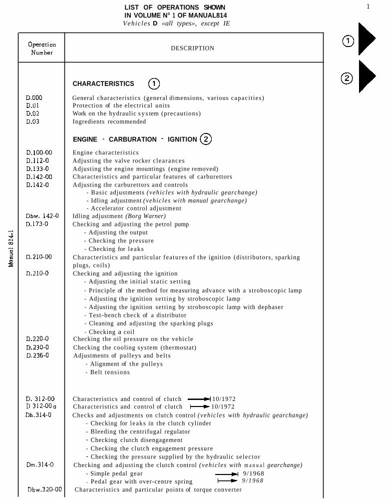
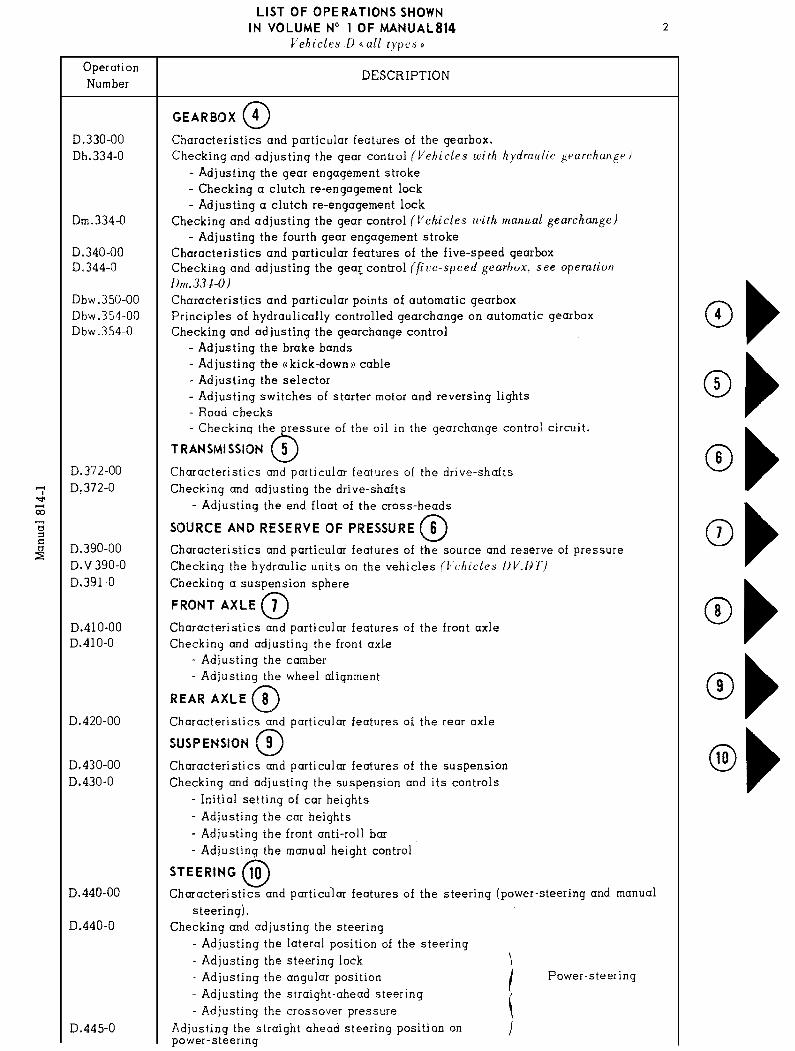
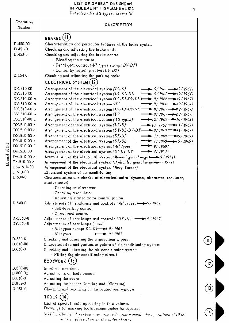
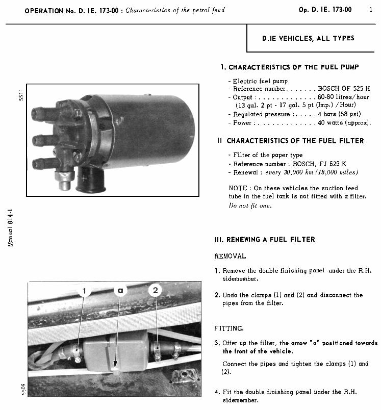
LIST OF OPERATIONS SHOWN IN VOLUME No 1 OF MANUAL814 Vehic les D «all types», except IE
DESCRIPTION
CHARACTERISTICS
General characterist ics (general dimensions, various capaci t ies ) Protection of the electr ical units Work on the hydraulic s y s tem (precautions) Ingredients recommended
ENGINE - CARBURATION - IGNITION
Engine characterist ics Adjusting the valve rocker c learances Adjusting the engine mountings (engine removed) Characterist ics and particular features of carburettors Adjusting the carburettors and controls
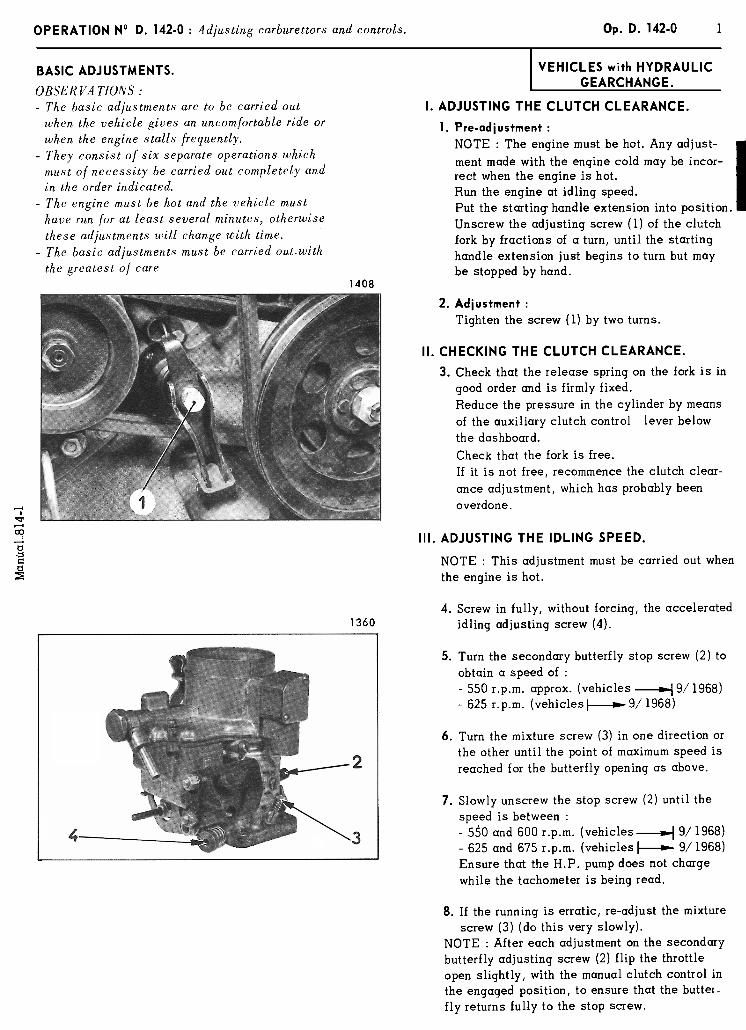
- Basic adjustments (vehic les with hydraulic gearchange) - Idling adjustment (vehic les with manual gearchange) - Accelerator control adjustment
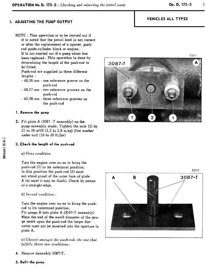
Idling adjustment (Borg Warner) Checking and adjusting the petrol pump
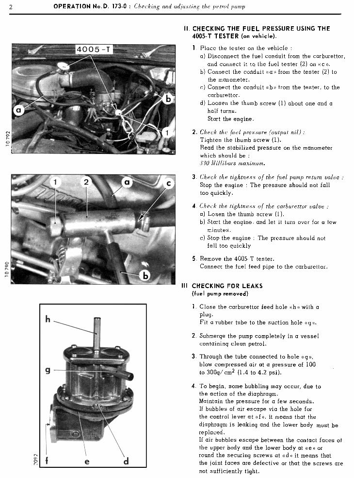
- Adjusting the output - Checking the pressure - Checking for l eaks
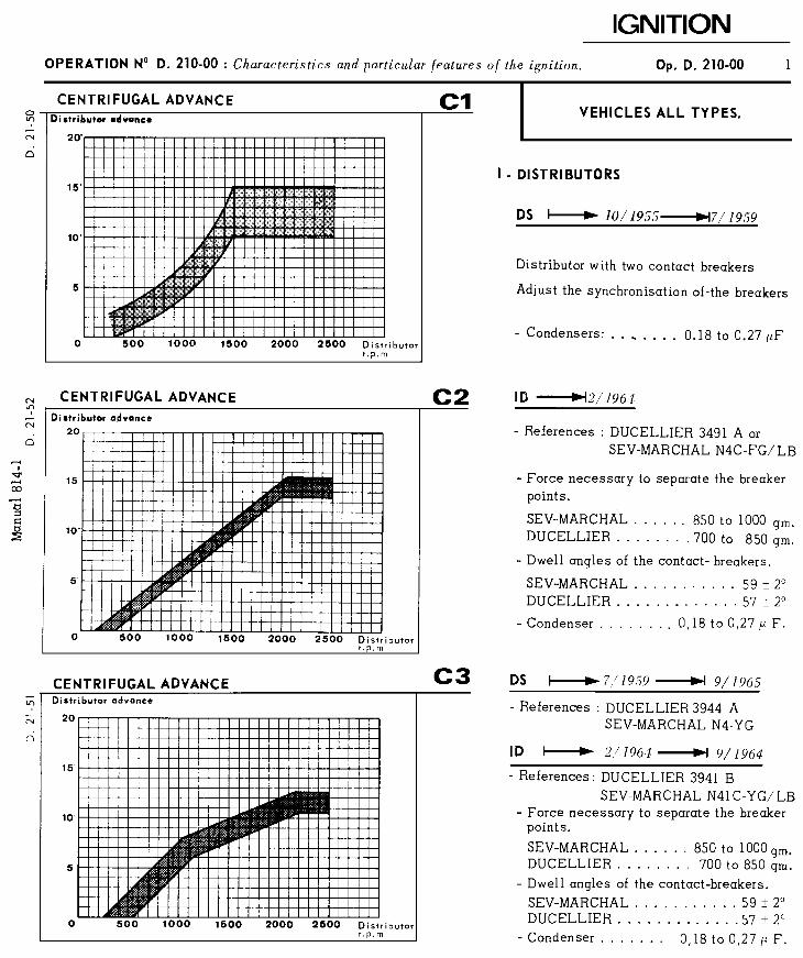
Characterist ics and particular fea tures of the ignition (distr ibutors, sparking plugs, coils) Checking and adjusting the ignition
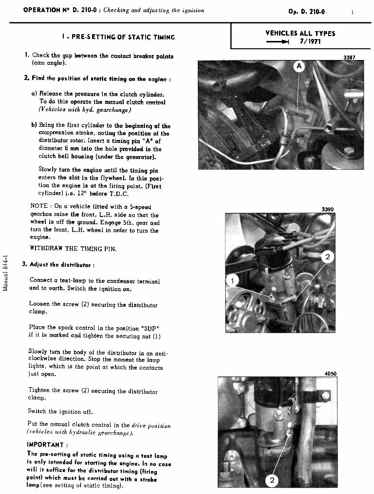
- Adjusting the ini t ial s t a t i c se t t ing
- Principle of the method for measuring advance with a stroboscopic lamp - Adjusting the ignition se t t ing by stroboscopic lamp - Adjusting the ignition set t ing by stroboscopic lamp with dephaser - Test-bench check of a distributor - Cleaning and adjusting the sparking plugs - Checking a coil
Checking the oil pressure on the vehicle Checking the cooling system (thermostat) Adjustments of pulleys and be l t s
- Alignment of t he pulleys - Belt tens ions
Characterist ics and control of clutch 10/1972Characterist ics and control of clutch 10/1972 Checks and adjustments on clutch control (vehic les with hydraulic gearchange)
- Checking for l eaks in the clutch cylinder - Bleeding the centrifugal regulator - Checking clutch disengagement - Checking the clutch engagement pressure - Checking the pressure supplied by the hydraulic se lec tor
Checking and adjust ing the clutch control (vehic les with m a n u a l gearchange) - Simple pedal gear 9/1968 - Pedal gear with over-centre spring 9 / 1 9 6 8
Characterist ics and particular points of torque converter

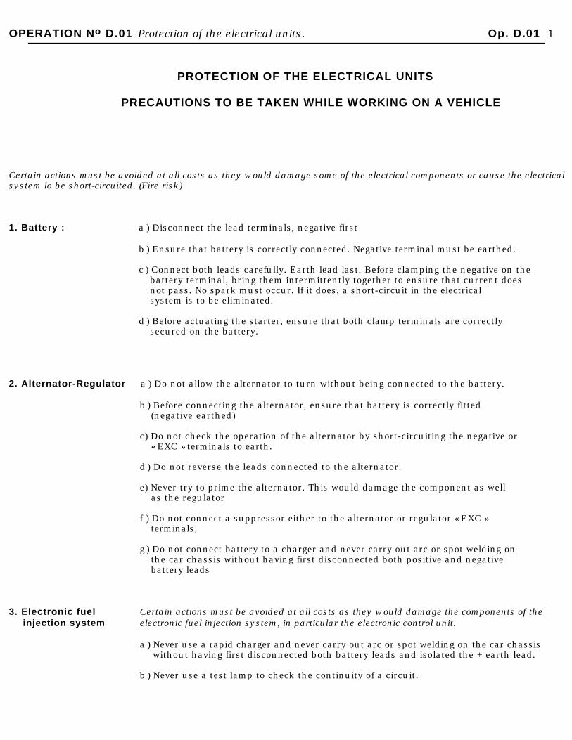
OPERATION No D.01 Protection of the electrical units. Op. D.01 1
PROTECTION OF THE ELECTRICAL UNITS
PRECAUTIONS TO BE TAKEN WHILE WORKING ON A VEHICLE
Certain actions must be avoided at all costs as they would damage some of the electrical components or cause the electrical system lo be short-circuited. (Fire risk)
1. Battery : a ) Disconnect the lead terminals, negative first
b ) Ensure that battery is correctly connected. Negative terminal must be earthed.
c ) Connect both leads carefully. Earth lead last. Before clamping the negative on thebattery terminal, bring them intermittently together to ensure that current doesnot pass. No spark must occur. If it does, a short-circuit in the electricalsystem is to be eliminated.
d ) Before actuating the starter, ensure that both clamp terminals are correctlysecured on the battery.
2. Alternator-Regulator a ) Do not allow the alternator to turn without being connected to the battery.
b ) Before connecting the alternator, ensure that battery is correctly fitted(negative earthed)
c) Do not check the operation of the alternator by short-circuiting the negative or« EXC » terminals to earth.
d ) Do not reverse the leads connected to the alternator.
e) Never try to prime the alternator. This would damage the component as wellas the regulator
f ) Do not connect a suppressor either to the alternator or regulator « EXC »terminals,
g ) Do not connect battery to a charger and never carry out arc or spot welding onthe car chassis without having first disconnected both positive and negativebattery leads
3. Electronic fuel Certain actions must be avoided at all costs as they would damage the components of the injection system electronic fuel injection system, in particular the electronic control unit.
a ) Never use a rapid charger and never carry out arc or spot welding on the car chassis without having first disconnected both battery leads and isolated the + earth lead.
b ) Never use a test lamp to check the continuity of a circuit.

2 OPERATION No D.01 Protection of the electrical units.
c) Never strike a spark to check the continuity of a lead.
d) Never start a vehicle with a voltage exceeding 12 volts.
e) Never force a connector onto the unit concerned.Take note of the inhibitor chamfers.
f) Only withdraw the connectors by taking hold of the sides and never by pullingon the leads. Check that the rubber caps completely cover the connectorswhen they are fully inserted.
g) The precautions to be taken during the alternator check also apply in thiscase.
h) Never alter the adjustment the exterior potentiometer of the electronic controlunits fitted since April 1971.
4. Ignition coil : a) Connect the supply lead of the coil to the ballast resistor terminal and not to thecoil itself.
b) Connect the suppressor with a jump lead to the ballast resistor terminal and notto the coil itself. Only fit the suppressor recommended by the factory.
5. Quartz-iodine Bulb : a) Switch off the headlamps to replace a bulb. If the headlamps have just beenused, it is advisable to allow the bulbs to cool a few minutes before handlingthe faulty one.
b) Do not touch the Q.I. bulb with the fingers. Should you accidentally touch abulb, it should be wiped with soapy water and dried with a lint-free cloth.
OPERATION No D.02: Work on the Hydraulic system. Op. D. 02 1
CARS WITH SYNTHETIC HYDRAULIC FLUID.
L.H.S.2The D vehicles produced up to September 1966 use a red fluid of synthetic base in their hydraulic circuits(Fluid L.H.S.2)
The main reservoir, steering unit, HP pump ( 7 pistons ), suspension spheres and accumulators are painted black.
The general instructions given earlier apply to these cars, provided that the following instructions are scrupulouslyobserved :
Cleaning :
Use alcohol only.
Assembly :
Follow the detailed operations in the Manual.
If seals or components need lubricating before assembly, use only synthetic fluid L.H.S.2.
If a component in contact with the suspension fluid must be greased ( e.g. steering pinion needles ) use only acastor grease, such as ANTAR RC.
7 Rubber parts :
Use only those seals, tubes and diaphragms made for use with synthetic fluid L.H.S.2. Never fit parts of the samedimensions but intended for use with other fluids.
All seals with white markings must of necessity be renewed after dismantling. We have sent you a « Table of Seals »giving you the part numbers of the only items suitable for use with the synthetic fluid.
Units :
Use only units intended for use in systems containing L.H.S. fluid. Certain units are painted black, but in nocase must units with green markings be used.
Testing :
Use test - bench 2290-T.
This test bench is painted grey and the accessories bear no marking.
These accessories, as well as the gauges, must only be used on vehicles functioning with synthetic fluid L.H.S.2.
Never use them with any other fluid or free testing units intended to function with any other fluid.
Hydraulic Fluid :
Use only factory approved fluids bearing the symbol L.H.S.2.
BLACK RESERVOIR : use SYNTHETIC FLUID L.H.S.2.
2 OPERATION No D.02: Work on the Hydraulic system.
CARS WITH MINERAL HYDRAULIC FLUID.
L.H.MD vehicles produced since September 1966, with the exception of certain models for export markets, use a green fluid of mineral base in their hydraulic circuits (fluid L.H.M. ).
The main reservoir and the hydraulic units are printed green or bear green identification marks.
The general instructions given earlier apply to these vehicles provided that the following instructions are scrupu-lously observed.
Cleaning :
Use petrol or white spirit only.
Assembly :
Follow the detailed operations in the Manual.
If seals or units need lubricating before assembly, use only mineral fluid L.H.M.
If a component in contact with the suspension fluid must be greased, use only a mineral grease «universal joint grease» or bearing grease (see table of oils and greases ).
Rubber parts :
Use only those seals, tubes and diaphragms made for use with mineral fluid L.H.M.
Never fit parts of the same dimensions but intended for use with other fluids.
All seals bearing white markings must of necessity be renewed after dismantling.
We have sent you a « Table of Seals » giving you the part numbers of the only items suitable for use with mineral fluid.
Units :
Use only units with the green identification colour and intended for use in systems containing mineral fluid L.H.M.
Testing :
Use test-bench 3654 - T and its accessories 3655 -T.
This test-bench is painted green and the accessories bear green markings.
These accessories and the gauges must only be used on vehicles functioning with mineral fluid L.H.M.
Never use them with any other fluid or for testing units intended to function with any other fluid.
NOTE : The « Le Bozec » pump used on test-benches for injectors in Diesel engines can be used, after cleaning,for testing units functioning with mineral fluid L.H.M. The tests must be carried out, of course, with mineral fluid L.H.M.
Hydraulic fluid :
Use only factory approved fluids bearing the symbol L.H.M.
GREEN RESERVOIR : use MINERAL FLUID L.H.M.

OPERATION No D.02: Work on the Hydraulic system. Op. D. 02 3
VEHICLES ALL TYPES
WORK ON THE HYDRAULIC SYSTEMS
To ensure correct functioning of the hydraulic systems it is essential that the hydraulic fluid and all thecomponent parts shall be perfectly clean. The most stringent precautions must be taken when workingon the car and for the storage of fluids and parts.
1. STORAGE.
All pipes, units and spare parts must be protected from dust and possible knocks.
Seals and rubber pipes must not be exposed to dust, air, light, or heat, hydraulic fluid must be kept inits original containers, securely sealed. We recommend the use of one litre (1 3
4 Imp. pt) containersfor topping up or five litres. (8.8 Imp. pts. approx.) when draining and refilling in order to avoid keepingseveral open containers.
2. PRECAUTIONS DURING THE WORK.
Before starting work, wash the car carefully or at least the area in which work is to be carried out.Example :- When replacing a rear suspension cylinder, carefully wash the corresponding wheel arch.Before disconnecting a union, wash it and the surrounding area carefully with an appropriate solvent
Release the pressure.
Then proceed as follows :
a) Work on all units except brakes and brake control :1 ) Unscrew the bleed screw on the pressure regulator.2 ) Place the manual height control lever in the « low » position.
b) Work on the brake circuits :1 ) Unscrew the bleed screw on the pressure regulator.2 ) Place the manual height control in the « low » position
3 ) Connect a flexible pipe (plastic or rubber) to a front brake unit bleed screw or on the rear bleedscrew of the centrifugal regulator or on the bleed screw of the hydraulic fast idling device .Slacken the bleed screw and depress the brake pedal to release the pressure in the brake accumu-lator.
c ) Unions :If the union is situated below the level of fluid in the reservoir, drain the latter to avoid loss of fluidor close the pipe immediately with an appropriate plug or cap.The unions or union flange sealing plates must be fitted « freely » and without strain.
OPERATION No D.02: Work on the Hydraulic system. Op. D. 02. 5
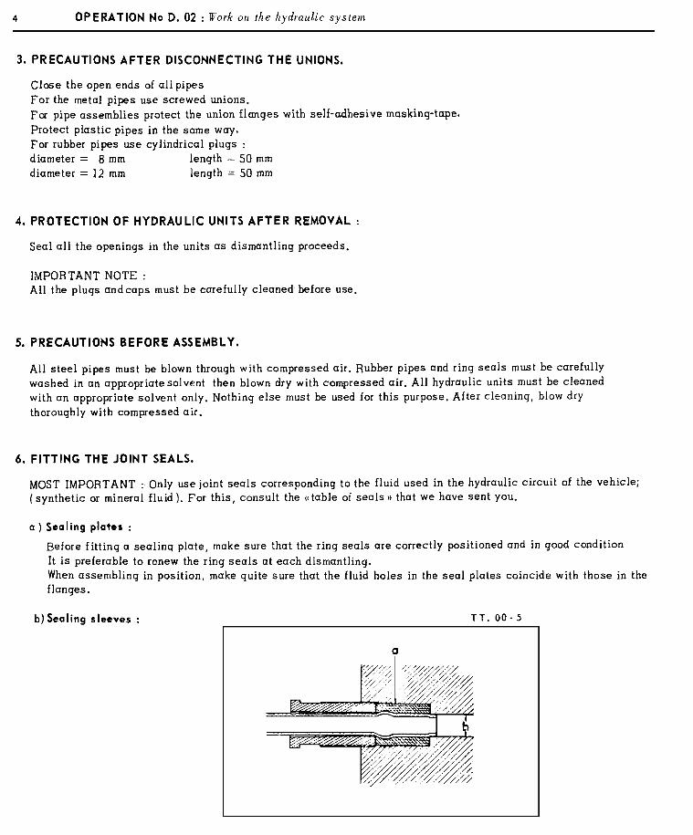
NOTE : All sealing sleeves must be renewed-after each dismantling operation :
1) Place a sealing sleeve « a » on the pipe. This sleeve should be set back 2 mm from the end ofthe pipe.
2) Centralise the pipe in the bore by aligning it with the axis of the bore.
MOST IMPORTANT : Make quite sure that the end of the pipe enters the small bore « b ».
3) Screw up the union nut by hand. On certain units the axis of the bore is oblique relative to theface of the boss for the nut.
4) Lightly tighten the nut.
Vehicles using synthetic fluid LHS ( main reservoir painted black)
Tighten the nut to 5,9 to 7,5 mΛN (0.6 to 0,8 m.kg ) ( 4 12 to 6 ft.lbs )
Vehicles using mineral fluid LHM ( main reservoir painted green )
Tighten the nut to 9 to 11 mΛN ( 9.9 to 1.1 m.kg ) ( 6 12 to 8 ft.lbs )
This slight tightening of the nut is sufficient to ensure a good seal. Excessive tightening willcause leakage.
c) Ring seals :
NOTE : These ring seals are so designed that their efficiency increases proportionately with the pressurein the pipes. Tightening the union does not increase sealing efficiency.
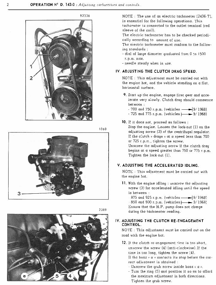
7. TACHOMETERS ( REVOLUTION INDICATORS )
Certain checks and adjustments cannot be effectively carried out without the use of a tachometer.To ensure accuracy when making these checks a precision instrument must be used. At 600 r.p.m.. particularly,it must be accurate to within ± 20 r.p.m.
Electric tachometers
The following instruments have been tested by us with satisfactory results :
« SOURIAU, type 1494» sold by Société SOURIAU, 13 rue du~Général Gallieni - 92 - BOULOGNE
« BOSCH, ref. 0681.199.592 » sold by the Société BOSCH-FRANCE, 32 Avenue Michelet, 93 - SAINT-OUEN
« SUN, model TDT. 12 » sold by the Société SUN-OVERSEAS, 19 rue de Paris - 92 - CLICHY
« CRIPTON, model BC. 40l/FA 7418 » sold by the Société NAUDER, 23 rue Boissière - 75 - PARIS (16e)
Electric tachometers should be checked periodically ( about once a month ). This check can be made by meansof a stroboscopic disc MR 630- 58/ 9.
Stroboscopic disc.
This simple instrument can be made by you. For the constructional dimensions ask for note MR. 630--58/9 fromour Service ‘ Division Technique Après- Vente ” 163, avenue Georges Clemenceau, 92-NANTERRE.The pulleys and belts must be in good condition, the pulleys correctly aligned and the belt tension correct.
Checking the tachometer.
The stroboscopic disc is used for checking the electric tachometer. It enables the following engine speeds to bechecked : 600 engine r.p.m. i.e. 300 HP pump r.p.m. : 1200 engine r.p.m. i.e. 600 pump r.p.m., and all the mul-tiples of 300 r.p.m. on the high pressure pump, but at engine speeds over 1200 r p m reading becomes verydifficult.
6 OPERATION No D.02: Work on the Hydraulic system.
8. PRESSURE GAUGES.
When carrying out checks or adjustments on hydraulic units of the car, the use of pressure gauges is essential.In just the same way as precision tachometers are necessary for accurate checking and adjustment, so it isnecessary to use sufficiently accurate pressure gauges.
The pressure gauges of test benches 2290-T and 3654-T are of the required accuracy. To preserve this accuracyit is necessary to protect the gauges by using dashpots ( dampers ). These are sold by Société FENWICK.
We strongly advise periodic checking of these pressure gauges, by comparison with a new pressure gaugereserved for the purpose, This pressure gauge can only be used with one hydraulic fluid (synthetic or mineral ).It must therefore be very clearly marked ( in red or in green accordingly).
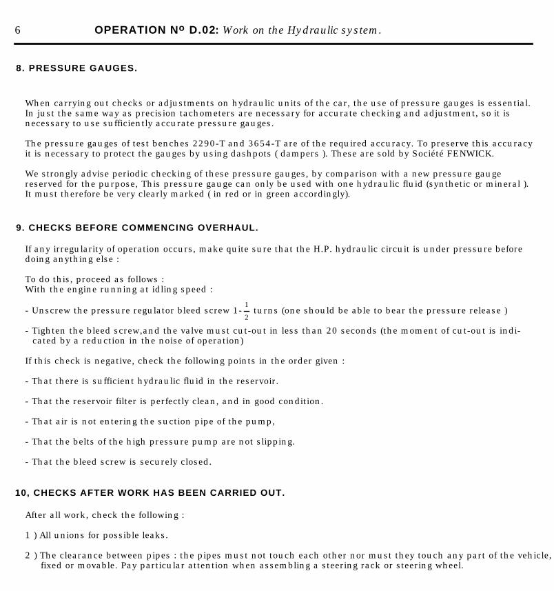
9. CHECKS BEFORE COMMENCING OVERHAUL.
If any irregularity of operation occurs, make quite sure that the H.P. hydraulic circuit is under pressure beforedoing anything else :
To do this, proceed as follows :With the engine running at idling speed :
- Unscrew the pressure regulator bleed screw 1-1
2 turns (one should be able to bear the pressure release )
- Tighten the bleed screw,and the valve must cut-out in less than 20 seconds (the moment of cut-out is indi-cated by a reduction in the noise of operation)
If this check is negative, check the following points in the order given :
- That there is sufficient hydraulic fluid in the reservoir.
- That the reservoir filter is perfectly clean, and in good condition.
- That air is not entering the suction pipe of the pump,
- That the belts of the high pressure pump are not slipping.
- That the bleed screw is securely closed.
10, CHECKS AFTER WORK HAS BEEN CARRIED OUT.
After all work, check the following :
1 ) All unions for possible leaks.
2 ) The clearance between pipes : the pipes must not touch each other nor must they touch any part of the vehicle,fixed or movable. Pay particular attention when assembling a steering rack or steering wheel.
10 OPERATION No D.02: Work on the Hydraulic system.
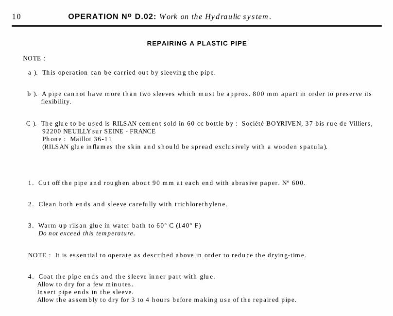
REPAIRING A PLASTIC PIPE
NOTE :
a ). This operation can be carried out by sleeving the pipe.
b ). A pipe cannot have more than two sleeves which must be approx. 800 mm apart in order to preserve its flexibility.
C ). The glue to be used is RILSAN cement sold in 60 cc bottle by : Société BOYRIVEN, 37 bis rue de Villiers, 92200 NEUILLY sur SEINE - FRANCEPhone : Maillot 36-11(RILSAN glue inflames the skin and should be spread exclusively with a wooden spatula).
1. Cut off the pipe and roughen about 90 mm at each end with abrasive paper. Nº 600.
2. Clean both ends and sleeve carefully with trichlorethylene.
3. Warm up rilsan glue in water bath to 60º C (140º F)Do not exceed this temperature.
NOTE : It is essential to operate as described above in order to reduce the drying-time.
4. Coat the pipe ends and the sleeve inner part with glue.Allow to dry for a few minutes.Insert pipe ends in the sleeve.Allow the assembly to dry for 3 to 4 hours before making use of the repaired pipe.
OPERATION No D.03: Approved pastes, glues and solvents. Op. D. 03 1
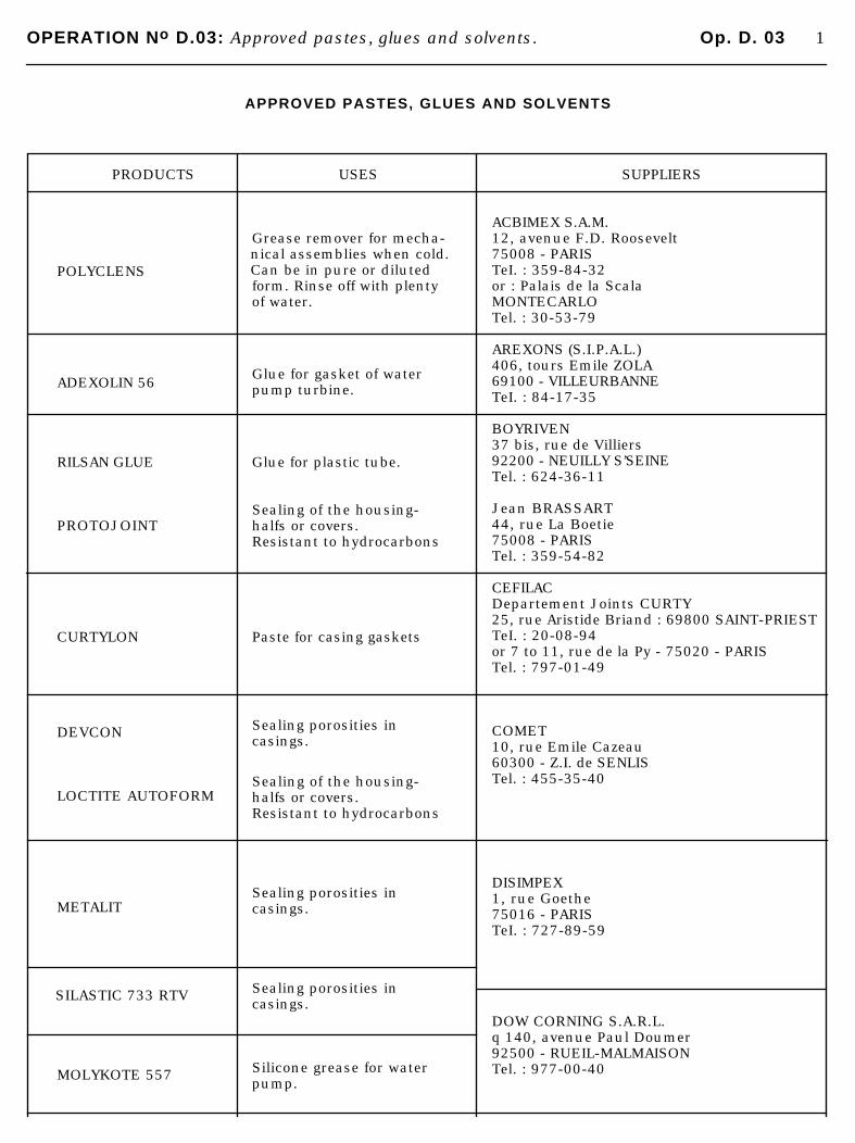
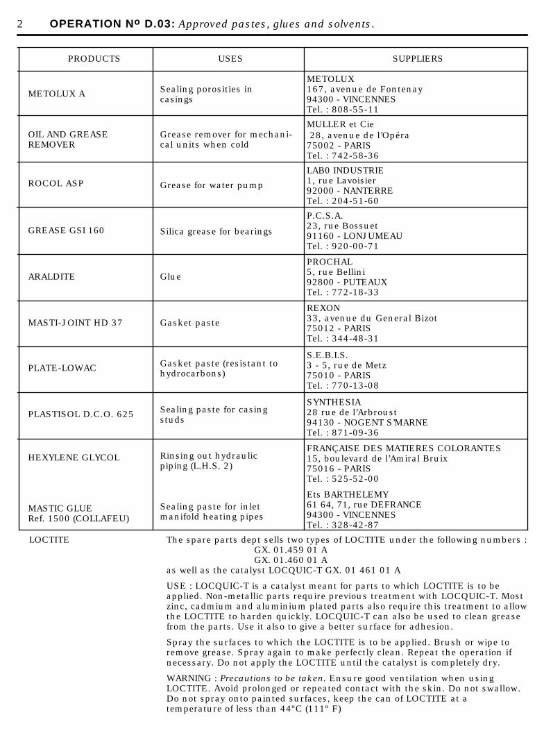
APPROVED PASTES, GLUES AND SOLVENTS
PRODUCTS
POLYCLENS
ADEXOLIN 56
RILSAN GLUE
PROTOJOINT
CURTYLON
DEVCON
LOCTITE AUTOFORM
METALIT
SILASTIC 733 RTV
MOLYKOTE 557
USES
Grease remover for mecha-nical assemblies when cold. Can be in pure or dilutedform. Rinse off with plentyof water.
Glue for gasket of waterpump turbine.
Glue for plastic tube.
Sealing of the housing-halfs or covers.Resistant to hydrocarbons
Paste for casing gaskets
Sealing porosities incasings.
Sealing of the housing-halfs or covers.Resistant to hydrocarbons
Sealing porosities incasings.
Sealing porosities incasings.
Silicone grease for waterpump.
SUPPLIERS
ACBIMEX S.A.M.12, avenue F.D. Roosevelt75008 - PARISTeI. : 359-84-32or : Palais de la ScalaMONTECARLOTel. : 30-53-79
AREXONS (S.I.P.A.L.)406, tours Emile ZOLA69100 - VILLEURBANNETeI. : 84-17-35
BOYRIVEN37 bis, rue de Villiers92200 - NEUILLY S’SEINETel. : 624-36-11
Jean BRASSART44, rue La Boetie75008 - PARISTel. : 359-54-82
CEFILACDepartement Joints CURTY25, rue Aristide Briand : 69800 SAINT-PRIESTTeI. : 20-08-94or 7 to 11, rue de la Py - 75020 - PARISTel. : 797-01-49
COMET10, rue Emile Cazeau60300 - Z.I. de SENLISTel. : 455-35-40
DISIMPEX1, rue Goethe75016 - PARISTeI. : 727-89-59
DOW CORNING S.A.R.L.q 140, avenue Paul Doumer92500 - RUEIL-MALMAISONTel. : 977-00-40
2 OPERATION No D.03: Approved pastes, glues and solvents.
PRODUCTS
METOLUX A
OIL AND GREASEREMOVER
ROCOL ASP
GREASE GSI 160
ARALDITE
MASTI-JOINT HD 37
PLATE-LOWAC
PLASTISOL D.C.O. 625
HEXYLENE GLYCOL
MASTIC GLUERef. 1500 (COLLAFEU)
USES
Sealing porosities incasings
Grease remover for mechani- cal units when cold
Grease for water pump
Silica grease for bearings
Glue
Gasket paste
Gasket paste (resistant tohydrocarbons)
Sealing paste for casing studs
Rinsing out hydraulic piping (L.H.S. 2)
Sealing paste for inletmanifold heating pipes
SUPPLIERS
METOLUX167, avenue de Fontenay94300 - VINCENNESTel. : 808-55-11
MULLER et Cie 28, avenue de l’Opéra75002 - PARISTel. : 742-58-36
LAB0 INDUSTRIE1, rue Lavoisier92000 - NANTERRETel. : 204-51-60
P.C.S.A.23, rue Bossuet91160 - LONJUMEAUTel. : 920-00-71
PROCHAL5, rue Bellini92800 - PUTEAUXTel. : 772-18-33
REXON33, avenue du General Bizot75012 - PARISTel. : 344-48-31
S.E.B.I.S.3 - 5, rue de Metz75010 - PARISTel. : 770-13-08
SYNTHESIA28 rue de l’Arbroust94130 - NOGENT S’MARNETel. : 871-09-36
FRANÇAISE DES MATIERES COLORANTES15, boulevard de l’Amiral Bruix75016 - PARISTel. : 525-52-00
Ets BARTHELEMY61 64, 71, rue DEFRANCE94300 - VINCENNESTel. : 328-42-87
LOCTITE The spare parts dept sells two types of LOCTITE under the following numbers :GX. 01.459 01 AGX. 01.460 01 A
as well as the catalyst LOCQUIC-T GX. 01 461 01 A
USE : LOCQUIC-T is a catalyst meant for parts to which LOCTITE is to beapplied. Non-metallic parts require previous treatment with LOCQUIC-T. Mostzinc, cadmium and aluminium plated parts also require this treatment to allowthe LOCTITE to harden quickly. LOCQUIC-T can also be used to clean greasefrom the parts. Use it also to give a better surface for adhesion.
Spray the surfaces to which the LOCTITE is to be applied. Brush or wipe toremove grease. Spray again to make perfectly clean. Repeat the operation ifnecessary. Do not apply the LOCTITE until the catalyst is completely dry.
WARNING : Precautions to be taken. Ensure good ventilation when usingLOCTITE. Avoid prolonged or repeated contact with the skin. Do not swallow.Do not spray onto painted surfaces, keep the can of LOCTITE at a temperature of less than 44ºC (111º F)
5
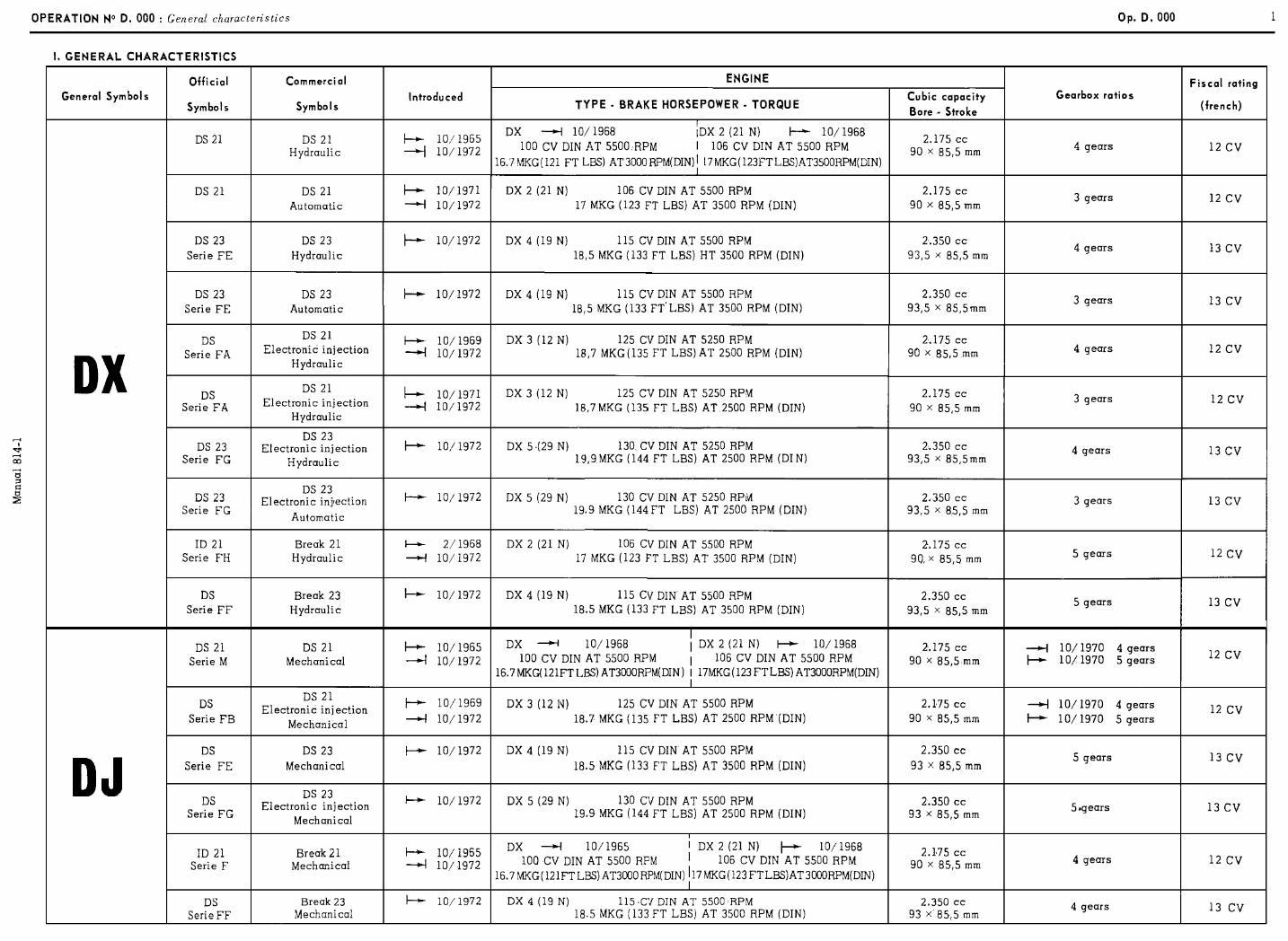
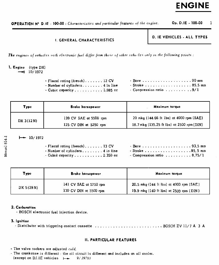
OPERATION N” D. 100-00 : Characteristics and particular feutures of the engine. Op. 0. 100.00
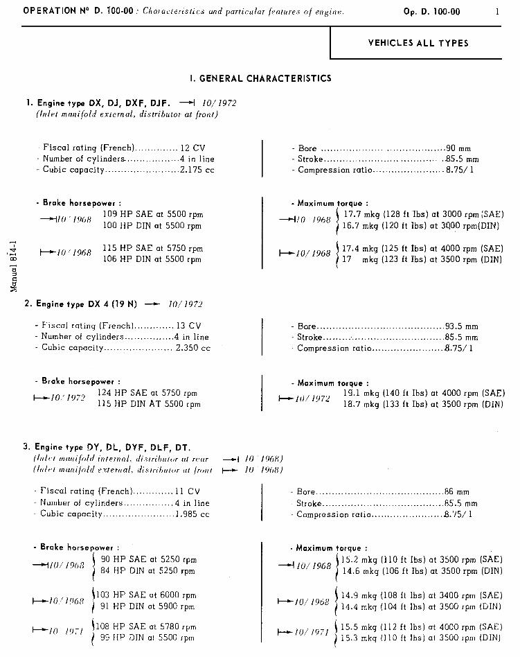
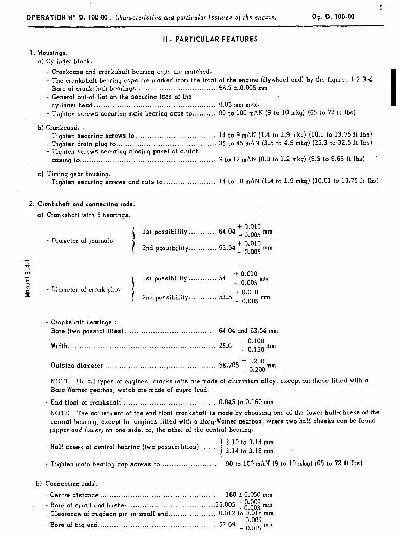
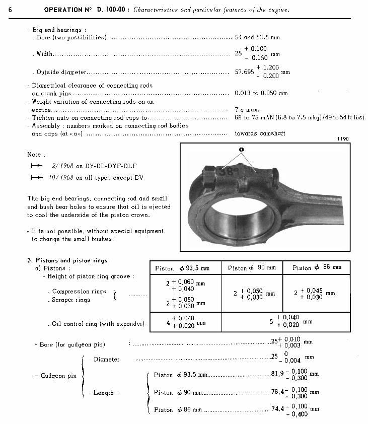
II - PARTICULAR FEATURES
1. Housings. .
a) Cylinder bloc&
- Crankcase and crankshaft bearing caps are matched. - The crankshaft bearing caps are marked from the front of the engine (flywheel end) by the figures l-2-3-4. - Bore of crankshaft bearings . . . . . . . . . . . . . . . . . . . . . . . . . . . . . . . . . 6a.7.+- .a.005 .mm - General out-of-flat on the securing face of the
cylinder head. . . . . . . . . . . . . . . . . . . . . . . . . . . . . . . . . . . . . . . . . . . . . . . . . . . . 0.05 mm max. - Tighten screws securing main bearing caps to.......... 90 to 100 mAN (9 to 10 mkgj (65 to 72 ft Ibs)
b’) Crankcase. - Tighten securing screws to . . . . . . . . . . . . . . . . . . . . . . . . . . . . . . . . . . 14 to 9 mAN (P.4 to 1.9 mkg) (10.1 to 13.75 ft Ibs) - Tighten drain plug to . . . . . . . . . . . . . . . . . . . . . . . . . . . . . . . . . . . . . . . . . . . 35 to 45 mAN (3.5 to 4.5 mkg) (25.3 to 32.5 ft Ibs) - Tighten screws securing closing panel of clutch
casing to . . . . . . . . . . . . . . . . . . . . . . . . . . . . . . . . . . . . . . . . . . . . . . . . . . . . . . . . . . 9 to 12 mhN (a.9 to L.2 mkg) (6.5 to 6.68 ft Ibs)
c) Timing gear housing. - Tighten securing screws and nuts to . . . . . . . . . . . . . . . . . . . . . . 14 to 10 mAN (I.4 to 1.9 mkg) (10.01 to 13.75 ft Ibs)
2. Crankshaft ond connecting rods.
a) Crankshaft with 5 bearings.
- Diameter of journals I + a.010
1st possibility . . . . . . . . . . . . 64.04 _ o oo5 mm .
2nd possibility . . . . . . . . . . . . 63.54 + a.010 - 0.005 mm
4 m + a.010 Fi 1st possibility. . . . . . . . . . . . 54 z
_ o oo5 mm
54 - Diameter of crank pins + c&o
2nd possibility. . . . . . . . . . . . 53.5 _ a oo5 mm .
- Crankshaft bearings : Bore (two possibilities) . . . . . . . . . . . . . . . . . . . . . . . . . . . . . . . . . . . . . . 64.04 and 63.54 mm
Width.. . . . . . . . . . . . . . . . . . . . . . . . . . . . . . . . . . . . . . . . . . . . . . . . . . . . . . . . . . . . . . 28.6 + a.100 - a.150 mm
Outside diameter.. . . . . . . . . . . . . . . . . . . . . . . . . . \ . . . . . . . . . . . . . . . . . . . . 68 705 + 1’200 . - 0.200mm
NOTE ?n all types of engines, crankshafts are made of aluminium-alloy, except on those fitted with a Borg-War&r gearbox, which are made of cupro-lead.
- End float of crankshaft . . . . . . . . . . . . . . . . . . . . . . . . . . . . . . . . . . . . . . . 0.045 to 0.160 mm
NOTE : The adjustment of the end float crankshaft is made by choosing one of the lower half-cheeks of the central bearing, except for engines fitted with a Borg-Warner gearbox, where two half-cheeks can be found (upper and louier) on one side, or, the other of the central bearing.
- Half-cheek of central bearing (two possibilities)....... i
3.10 to 3.14 mm 3.14 to 3.18 mm
- Tighten main bearing cap screws to . . . . . . . . . . . . . . . . . . . . . . . . 90 to 100 mAN (9 to 10 mkg) (65 to 72 ft Ibs)
b) Connecting rods.
- Centre distance . . . . . . . . . . . . . . . . . . . . . . . . . . . . . . . . . . . . . . . . . . . . . . . . . 160 ? 0.050 mm
- Bore of small end bushes . . . . . . . . . . . . . . . . . . . . . . . . . . . . . . . . . . . . . 25.005 t 0.009
- Cle&ance of gugdeon pin in small end . . . . . . . . . . . . . . . . . . . . _ O-003 mm
0.012 to 0.018 mm
- Bore of big end . . . . . . . . . . . . . . . . . . . . . . . . . . . . . . . . . . . . . . . . . . . . . . . . . . 57 69 + 0.005 _ o 015 mm
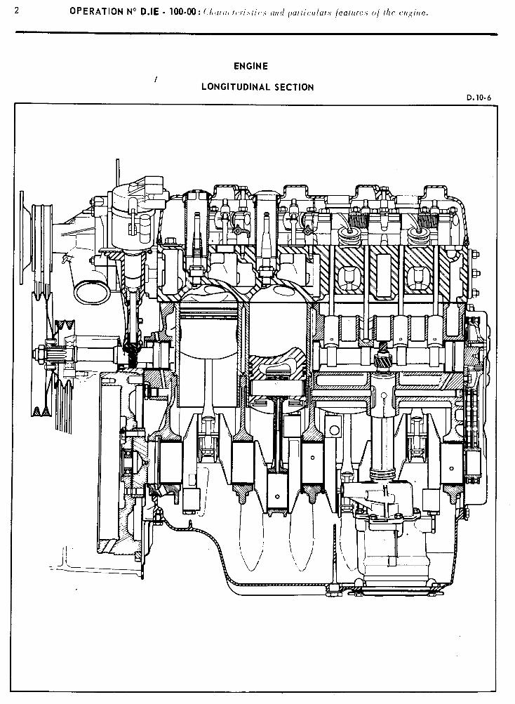
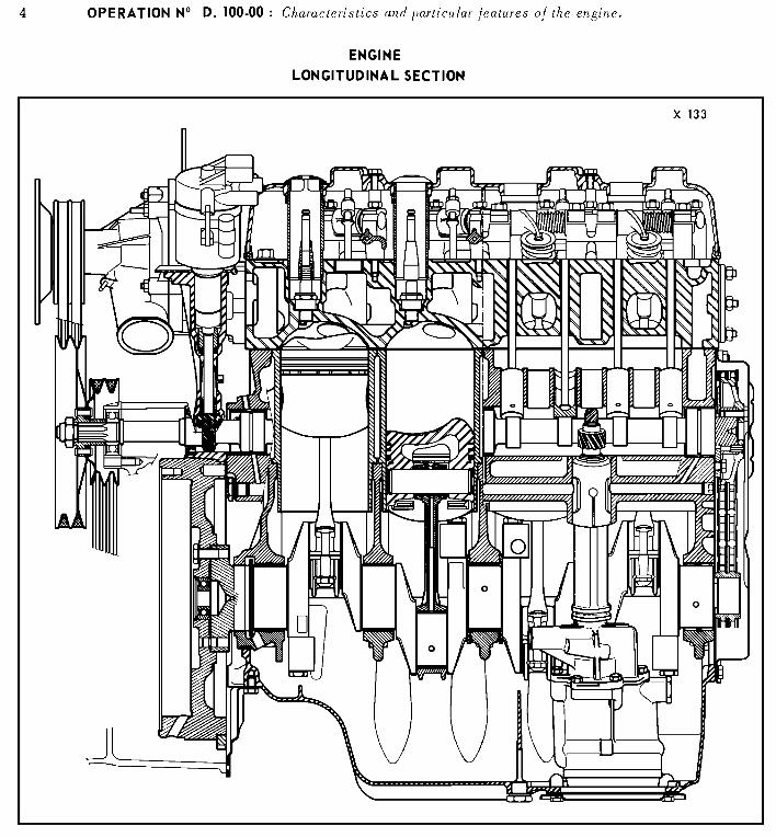
ENGINE /
LONGITUDINAL SECTION D. 10-6
Op. D.I E- 100-00
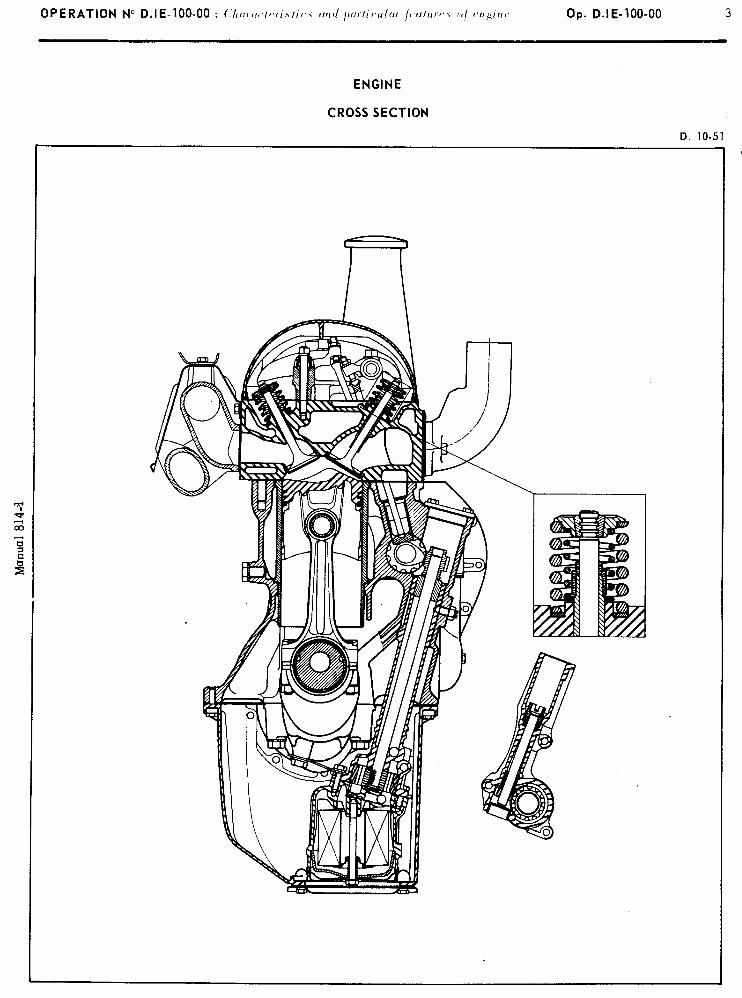
ENGINE
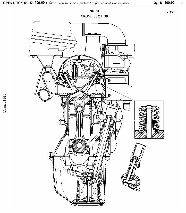
CROSS SECTION
D. lo-51
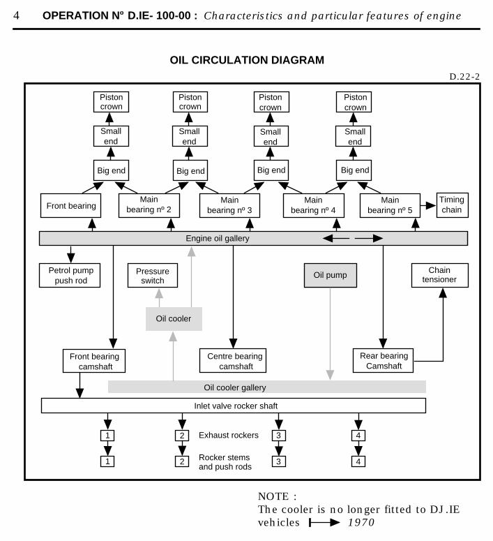
4 OPERATION Nº D.IE- 100-00 : Characteristics and particular features of engine
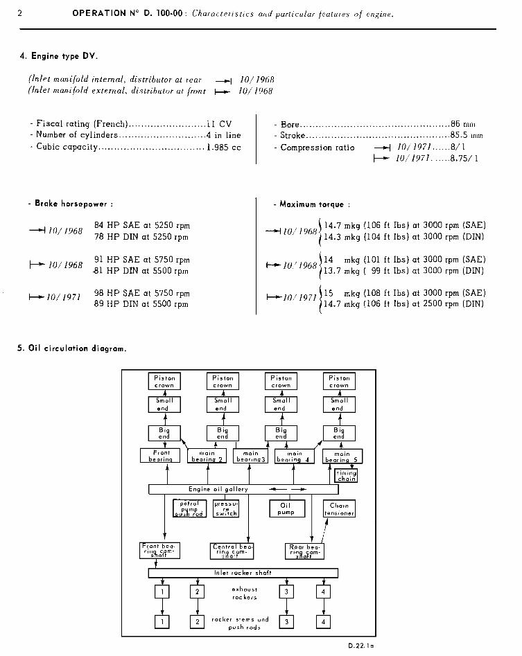
OIL CIRCULATION DIAGRAMD.22-2
NOTE : The cooler is no longer fitted to DJ.IEvehicles 1970
Engine oil gallery
Pistoncrown
Pistoncrown
Pistoncrown
Smallend
Smallend
Smallend
Big end Big end
Pistoncrown
Smallend
Big end Big end
Front bearingMain
bearing nº 2Main
bearing nº 3Main
bearing nº 4Main
bearing nº 5Timingchain
Pressureswitch
Oil pumpChain
tensioner
Rear bearing Camshaft
Front bearing camshaft
Centre bearing camshaft
Inlet valve rocker shaft
Exhaust rockers
Rocker stemsand push rods
Petrol pumppush rod
1 3
Oil cooler gallery
2 4
2 431
Oil cooler
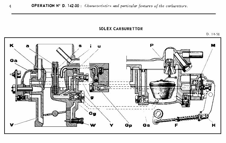
OPERATION Y’ 0. 142-00 : (:I rurar.iurislic.3 und purliculur jeulures in/ lhe curburelt0r.b. Op. 0. 142-00 3
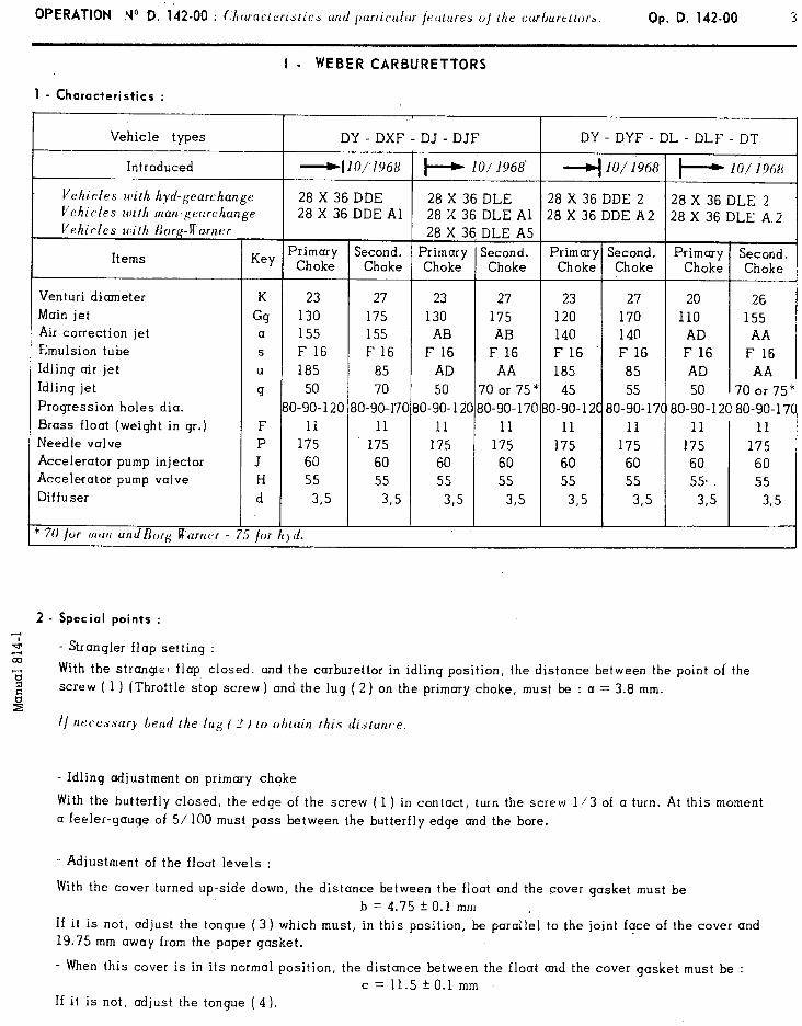
I - WEBERCARBURETTORS
1 - Characteristics :
Vehicle types
Introduced
Vehicles with hyd-gearchange Vehicles wirh man-gearchunge _. I’ehirles iiiilh Borg-Warner
Items
Venturi diameter
Main jet Air correction jet
Emulsion tube
Idling air jet
Idling jet
Progression holes dia.
Brass float (weight in gr.) Needle valve Accelerator pump injector
Accelerator pump valve Diffuser
’ 70 /or mt~t~ undBorg R’arncr - / or
Key
K
Gg a S
U
g
F P
J H
d
2 - Special points :
c;’ 4 .-4 - Strangler flap setting : -
8
L hl -
DY - DXF - DJ - DJF
J
Primary Choke
23
130 155
F 16
185
50
O-90-120 11
175 60
55
3,5
I d.
1 28 X 36 DLE A5
Second. Primal Choke Chokl
27 23
175 130
155 AB
F 16 F 16
85 AD
70 50
;O-90--170 80-90-I
11 11
175 175 60 60 55 55
3,s 3,
r Y 2
i
,201
5
Second. Choke
Prima Chok
27 23
175 120 AB 140
F 16 F 16 AA 185
70 or 75” 45
30-90-170 o-90- 1
11 11 175 175
60 60 55 55
3,s 3,s
DY - DYF - DL - DLF - DT I
4 lo/l968 1 c---) IO/1968 1
28 X 36 DDE 2 28 X 36 DLE 2 28 X 36 DDE A2 28 X 36 DLE A 2
1
27 20 26
170 110 155 140 AD AA
F 16 F 16 F 16
85 AD AA
55 50 70 or 75+ 2C 80-90-17t 80-90-12(! 80-90-17C
11 11 11
175 175 175
60 60 60
55 55 55
305 3,s 3,5
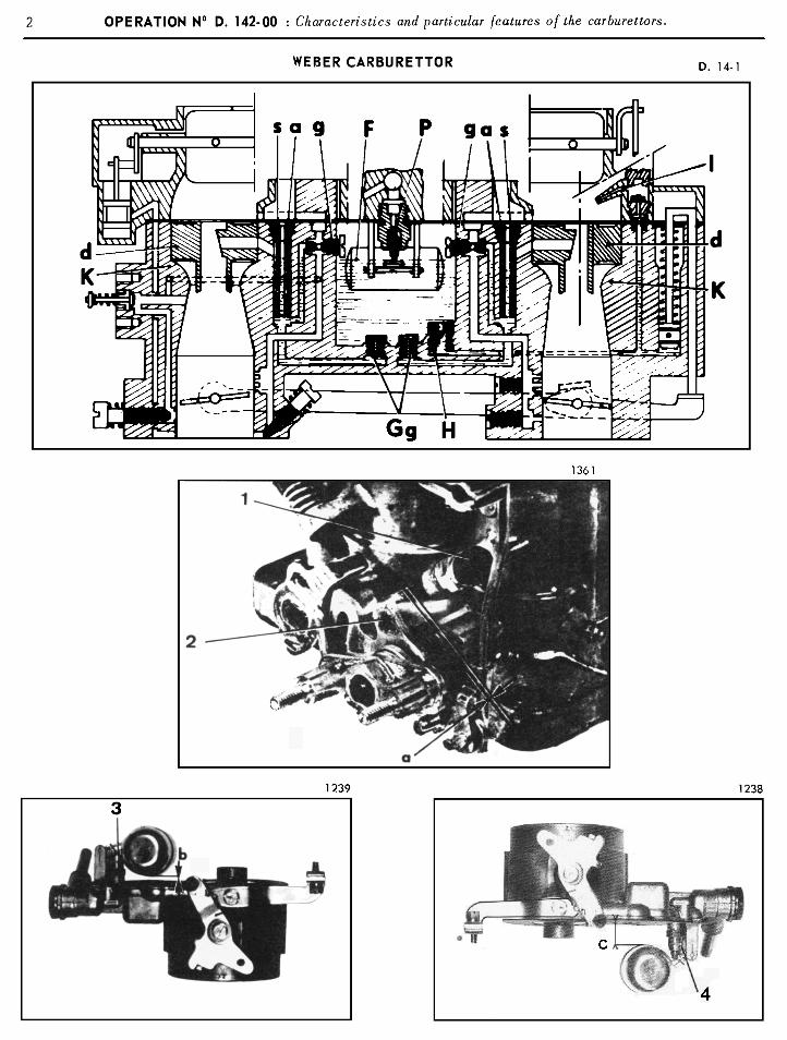
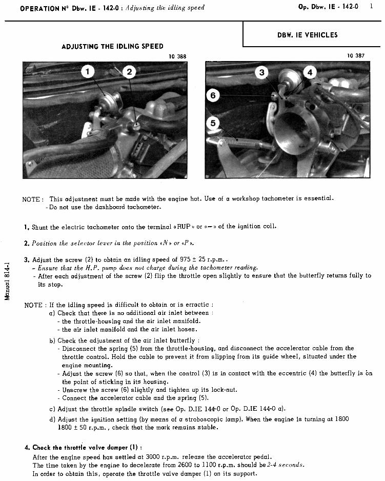
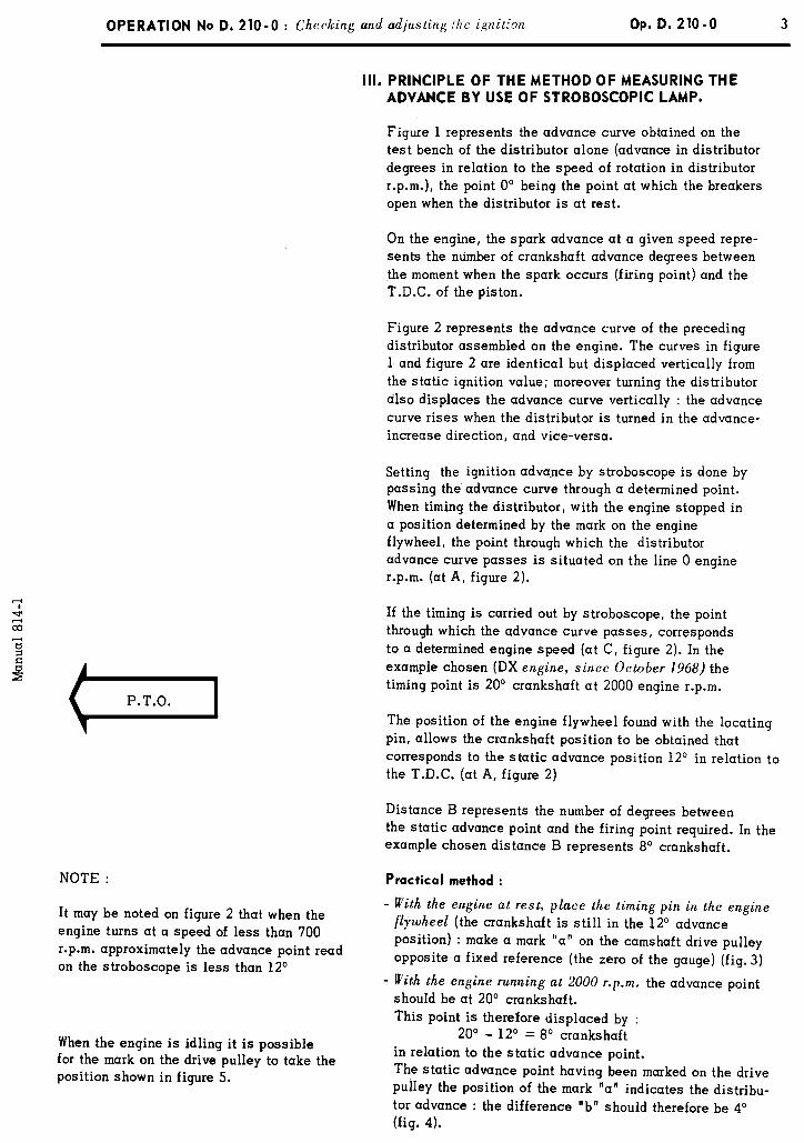
With the strangl er flap closed. and the carburettor in idling position, the distance between the point of the
screw ( 1 ) (Throttle stop screw) and the lug ( 2) on the primary choke, must be : a = 3.8 mm.
- Idling adjustment on primary chqke
With the butterfly closed, the edge of the screw (1 ) in contact, turn the screw l./ 3 of a turn. At this moment
a feeler-gauge of 5/ 100 must pass between the butterfly edge and the bore.
- Adjustment of the float levels :
With the cover turned up-side down, the distance between the float and the cover gasket must be b = 4.75 + 0.1 mm
If it is not, adjust the tongue (3) which must, in this position, be parallel to the joint face of the cover and
19.75 mm away from the paper gasket.
- When this cover is in its normal position, the distance between the float and the cover gasket must be : c = 11.5 t 0.1 mm
If it is not, adjust the tongue ( 4).

6 OPERATION No D. 142 - 00 : Characteristics und parlicular features of the car4urettors
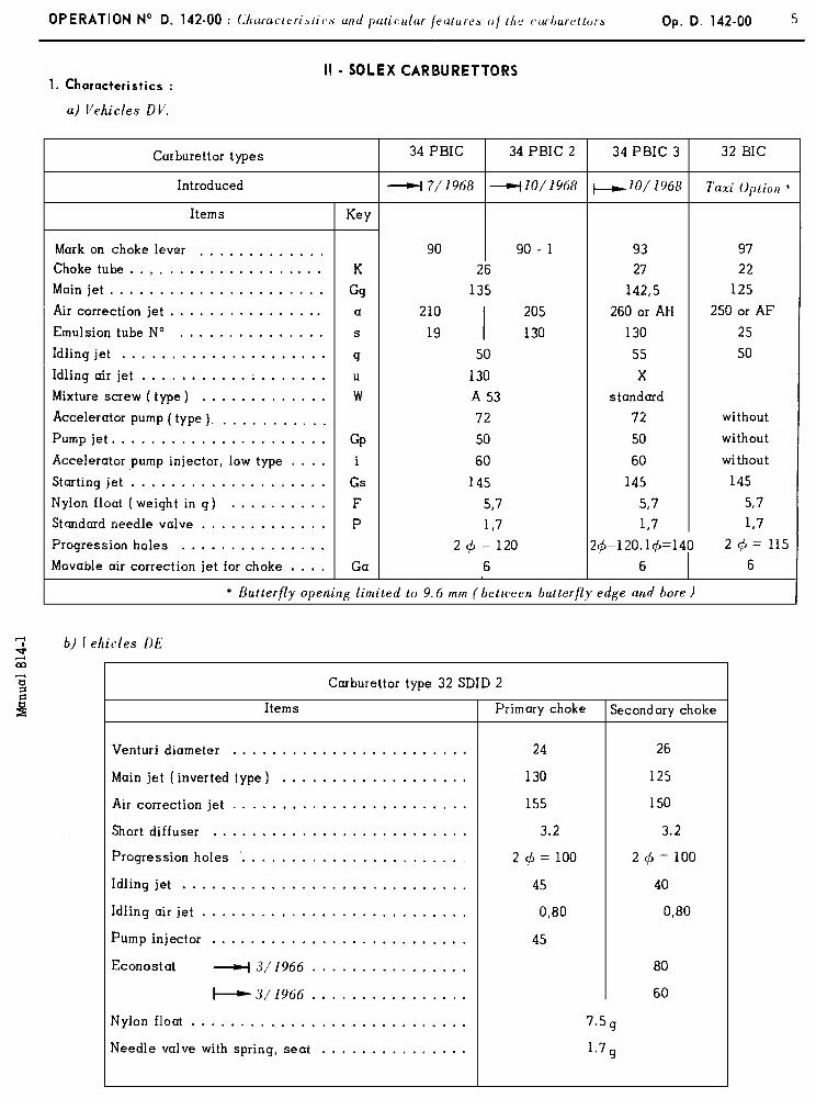
NOTE : Since February 1970 a certain number of DT zlehicles have been. fitted with SOLEX carburettors, 28 X .jC, SF/F.
Carburettor Types SOLEX 28 X 36 SFIF (MARK 26 )
Items Primary choke Secondary choke
Choke t,lbe ........................... 20 26
Main jet ............................. 120 145
Air correction jet ....................... 1 AD 2 AA
Diffuser ............................. No 56 980 N” 56 980
Emulsion tube ......................... N” 57 105 No 57 105
Idling jet ............................ 55 65
Idling air jet .......................... 90 90
Progression holes 1st hole ................ 90 100 .\ * .
2nd hole ................ 90 100
3rd hole ................ 110
Nylon float ........................... 5.25 g
I Needle valve with spring .................. 1.7
Accelerator pump ....................... diaphragm - type
1 Upper accelerator pump injector (steel ball) ..... 4 60
I Device for cold starting ................... Assisted mechanical strangler flap
Strangler flap closed : butterfly of primary I
choke open by ......................... 1.46 + O”O mm 0
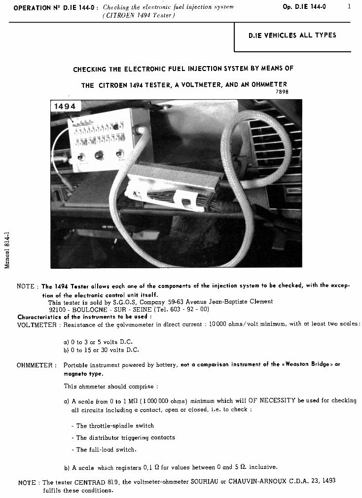
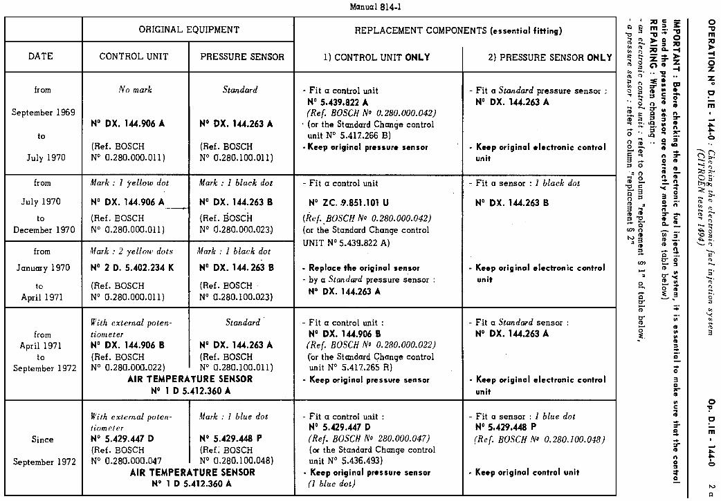
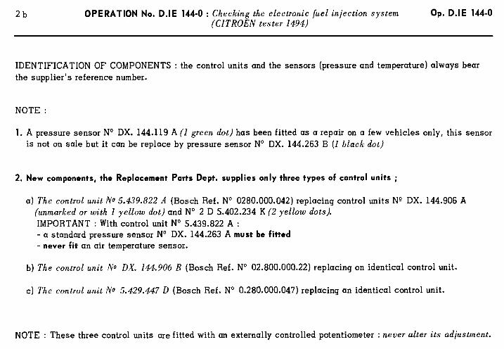
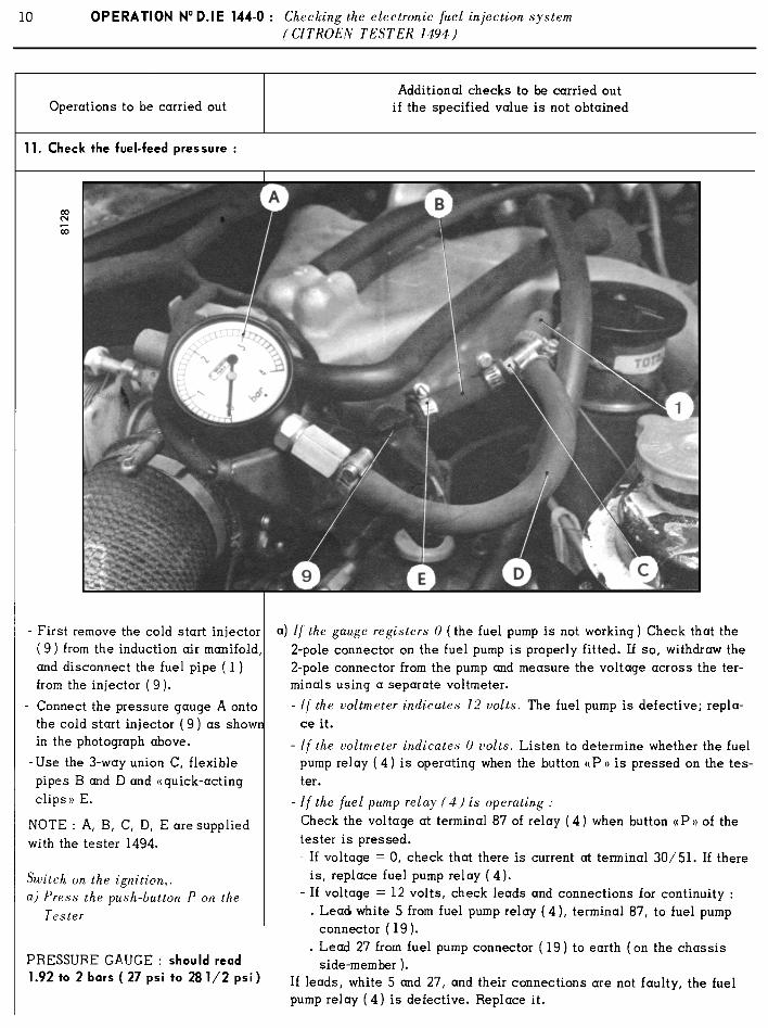
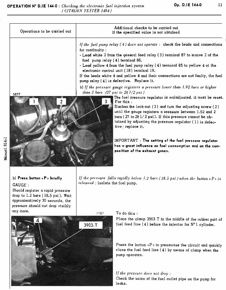
2 OPERATION No D.IE 144-0: Checking the electronic fuel injection system. ( CITROEN 1494 Tester )
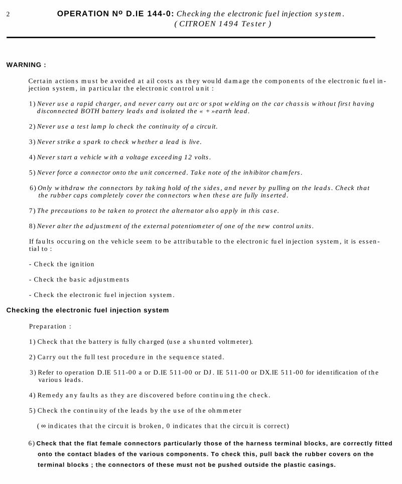
WARNING :
Certain actions must be avoided at ail costs as they would damage the components of the electronic fuel in-jection system, in particular the electronic control unit :
1) Never use a rapid charger, and never carry out arc or spot welding on the car chassis without first havingdisconnected BOTH battery leads and isolated the « + » earth lead.
2) Never use a test lamp lo check the continuity of a circuit.
3) Never strike a spark to check whether a lead is live.
4) Never start a vehicle with a voltage exceeding 12 volts.
5) Never force a connector onto the unit concerned. Take note of the inhibitor chamfers.
6) Only withdraw the connectors by taking hold of the sides, and never by pulling on the leads. Check thatthe rubber caps completely cover the connectors when these are fully inserted.
7) The precautions to be taken to protect the alternator also apply in this case.
8) Never alter the adjustment of the external potentiometer of one of the new control units.
If faults occuring on the vehicle seem to be attributable to the electronic fuel injection system, it is essen-tial to :
- Check the ignition
- Check the basic adjustments
- Check the electronic fuel injection system.
Checking the electronic fuel injection system
Preparation :
1) Check that the battery is fully charged (use a shunted voltmeter).
2) Carry out the full test procedure in the sequence stated.
3) Refer to operation D.IE 511-00 a or D.IE 511-00 or DJ. IE 511-00 or DX.IE 511-00 for identification of thevarious leads.
4) Remedy any faults as they are discovered before continuing the check.
5) Check the continuity of the leads by the use of the ohmmeter
( ∞ indicates that the circuit is broken, 0 indicates that the circuit is correct)
6) Check that the flat female connectors particularly those of the harness terminal blocks, are correctly fitted
onto the contact blades of the various components. To check this, pull back the rubber covers on the
terminal blocks ; the connectors of these must not be pushed outside the plastic casings.
4 OPERATION No D.IE 144-O : Checking the electronic juel injection system ( Cl TR0E.V 1191 Tester )
Operations to be carried out
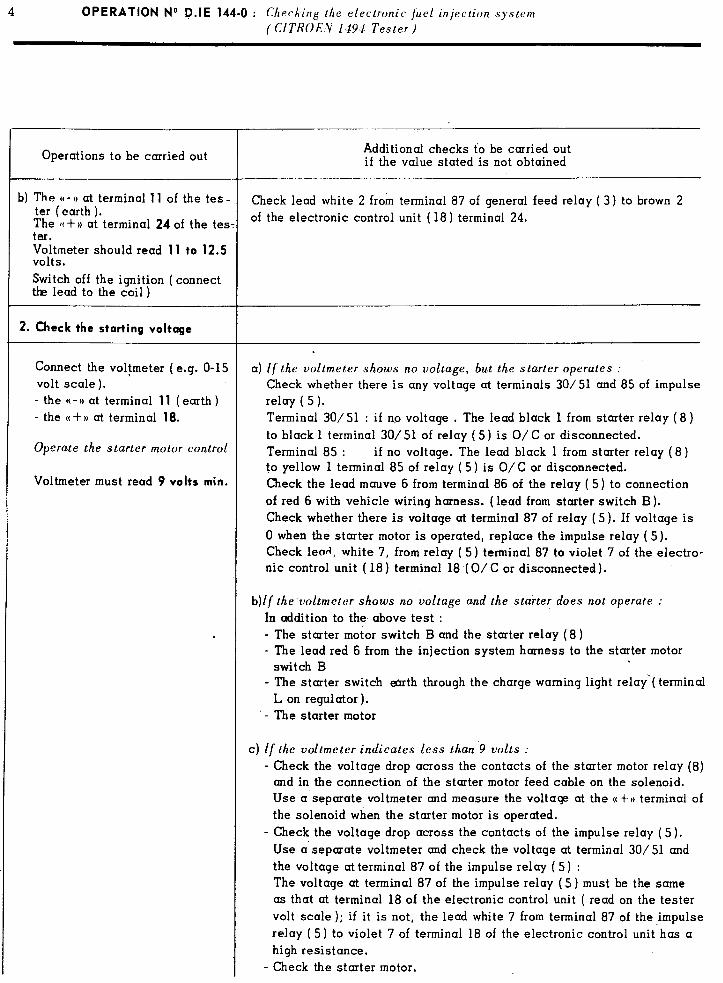
b) The (( - )) at terminal 11 of the tes - ter (earth ). The N + r) at terminal 24 of the tes ter. Voltmeter should read 11 to 12.5 volts. Switch off the ignition (connect the lead to the coil )
2. Check the starting voltage
Connect the voltmeter ( e.g. O-15 volt scale). ’ - the M- H at terminal 11 ( earth ) - the N + )) at terminal 18.
Operate the starter motor control
Voltmeter must read 9 volts min.
Additional checks to be carried out if the value stated is not obtained
Check lead white 2 from terminal 87 of general feed relay ( 3) to brown 2 of the electronic control unit ( 18) terminal 24.
a) If the voltmeter shows no voltage, but the starter operates : Check whether there is any voltage at terminals 30/51 and 85 of impulse relay ( 5 ). Terminal 30/ 51 : if no voltage . The lead black 1 from starter relay ( 8 ) to black 1 terminal 30/51 of relay (5) is O/C or disconnected. Terminal 85 : if no voltage. The lead black 1 from starter relay (8) to yellow 1 terminal 85 of relay ( 5 ) is O/C or disconnected. Check the lead mauve 6 from terminal 86 of the relay ( 5) to connection of red 6 with vehicle wiring harness. (lead from starter switch B). Check whether there is voltage at terminal 87 of relay ( 5). If voltage is 0 when the starter motor is operated, replace the impulse relay ( 5). Check lead, white 7, from relay ( 5) terminal 87 to violet 7 of the electro- nic control unit ( 18) terminal 18 (O/C or disconnected).
b)lf the voltmeter shows no voltage and the starter does not operate :
In addition to the above test : - The starter motor switch B and the starter relay (8) - The lead red 6 from the injection system harness to the starter motor
switch B - The starter switch emth through the charge warning light relay‘( terminal
L on regulator). .- The starter motor
c) if the voltmeter indicates less than 9 volts :
- Check the voltoge drop across the contacts of the starter motor relay (8) and in the connection of the starter motor feed cable on the solenoid. Use a‘separate voltmeter and measure the voltage at the N+P) terminal of the solenoid when the starter motor is operated.
- Check the voltage drop across the contacts of the impulse relay (5). Use a separate voltmeter and check the voltage at terminal 30/51 and the voltage at terminal 87 of the impulse relay (5) : The voltage at terminal 87 of the impulse relay (5) must be the same as that at terminal 18 of the electronic control unit ( read on the tester volt scale ); if it is not, the lead white 7 from terminal 87 of the impulse relay (5) to violet 7 of terminal 18 of the electronic control unit has a high resistance.
- Check the starter motor.
For these vohiclcs, the checking of the starting voltage is as follows :
(refer to diagram DJ.IE 511-00 and to the lead identification table on page 21).
r 2. Checking the starting voltage (DI.IE 4/ 1971
Connect the voltmeter (e.g 0 - 15 v scale) - Negative to terminal 11 (eprth) - Positive to terminal 18
.lctivate the starter motor.
OPERATION No. D.IE 144-O : Checking the electronic fuel injection system (CITROEN TESTER 1194)
Op. D.IE 144-O ,4 a
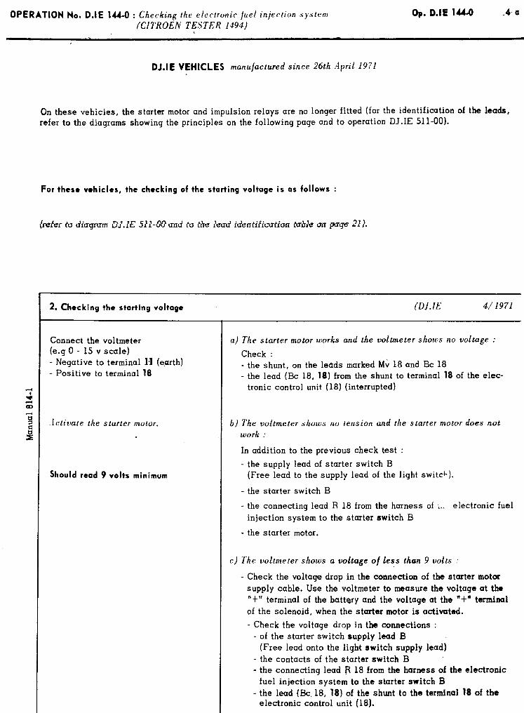
DJ.IE VEHICLES manufactured since 26th April 1971
On these vehicles, the starter motor and impulsion relays are no longer fitted (for the identification of the lea&, refer to the diagrams showing the principles on the following page and to operation DJ.IE 511-00).
I
a) The starter motor works and the voltmeter shows no voltuge :
Check : - the shunt, on the leads marked Mv 18 and Bc 18 - the lead (Bc 18, 18) from the shunt to terminal 18 of the elec-
tronic control unit (18) (interrupted)
b) The voltmeter shows no tension and the starter motor does not work :
Should read 9 volts minimum
In addition to the previous check test :
the supply lead of starter switch B
- (F ree lead to the supply lead of the light switch).
- the starter switch B
- the connecting lead R 18 from tbe harness of L. electronic fuel
injection system to the starter switch B
- the starter motor.
c) The voltmeter shows a voltage o/less than 9 volts :
- Check the voltage drop in the connection of the starter motor supply cable. Use the voltmeter to measure the voltage at the “t” terminal of the battery and the voltage at the “t” terminal
of the solenoid, when the starter motor is activated.
- Check the voltage drop in the connections : - of the starter switch supply lead B
(Free lead onto the light switch supply lead) - the contacts of the starter switch B - the connecting lead B 18 from the harness of the electronic
fuel injection system to the starter switch B - the lead (Bc. 18, 18) of the shunt to the terminal 18 of the
electronic control unit (18).
OPERATION No D.IE 144-O : Checking the electronic fuel injection system (CITROEN TESTER 1494)
Op. D.IE 144-O .8- a
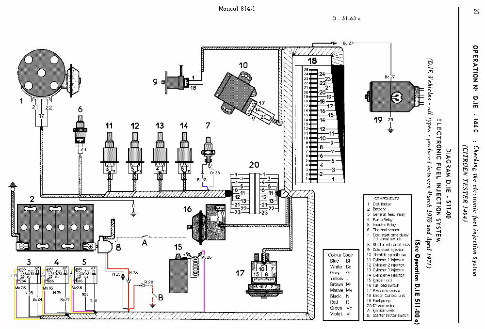
D.IE VEHICLES ALL TYPES (produced since 5th April 1971)
The electronic fuel injection control has been modified as follows on these models :
- Addition of an air temperature sensor fitted on the air filter. - Modification of the electronic control unit : (see pages 2 a and 2 b) - Modification of the injection system wiring harness (see operations DX.IE 511-00 and DJ.IE 51-1430)
On these vehicles the checking of the electronic fuel injection system diff ers only to the extent that the air
temperature sensor must also be checked.
For these vehicles after checking the resistance of the thcrmol sensor ($8, page 8), the resistance of the air
temperature sensor must also be checked :
(refer to diagrams DX.IE 511-00 and DJ.IE 511-00 and to the lead identification tables on pages 20 and 21).
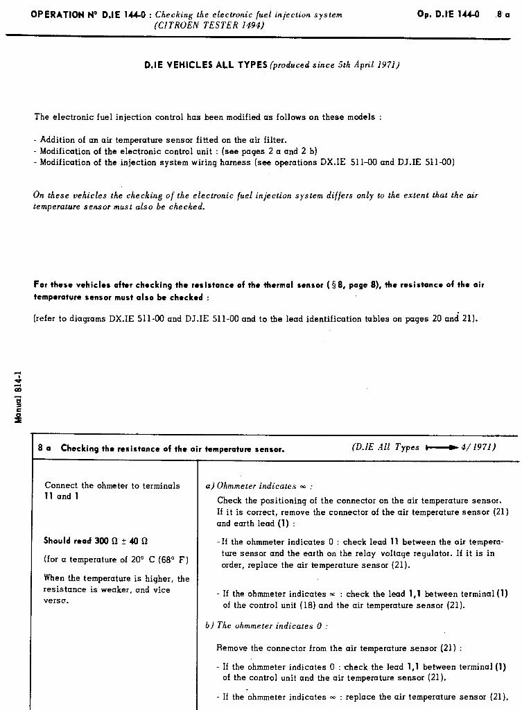
r 8 a Checking the resistance of the air temperature sensor. (D.lE All Types c-----) 4/ 1971)
Connect the ohmeter to terminals 11 and 1
Should read 300 Q + 40 Q
(for a temperature of 20’ C (68” F)
When the temperature is higher, the resistance is weaker, and vice verse.
a) Ohmmeter indicates 00 :
Check the positioning of the connector on the air temperature sensor.
I f it is correct, remove the connector of the air temperature sensor (21) and earth lead (1) :
- I f the ohmmeter indicates 0 : check lead 11 between the air tempera-
ture sensor and the earth on the relay voltage regulator. I f it is in
order, replace the air temperature sensor (21).
- I f the ohmmeter indicates m : check the lead 1,l between terminal (1) of the control unit (18) and the air temperature sensor (21).
b) The ohmmeter indicates 0 :
Remove the connector from the air temperature sensor (21) :
- I f the ohmmeter indicates 0 : check the lead 1,l between terminal (1)
of the control unit and the air temperature sensor (21). v
- I f the ohmmeter indicates m : replace the air temperature sensor (21).
OPERATION No D.IE 144-O : Checking the electronic fuel injection s).stem
( CITKOEfiV TLSTEK I$94 )
Op. D.IE 144-O -9
Operations to be carried out
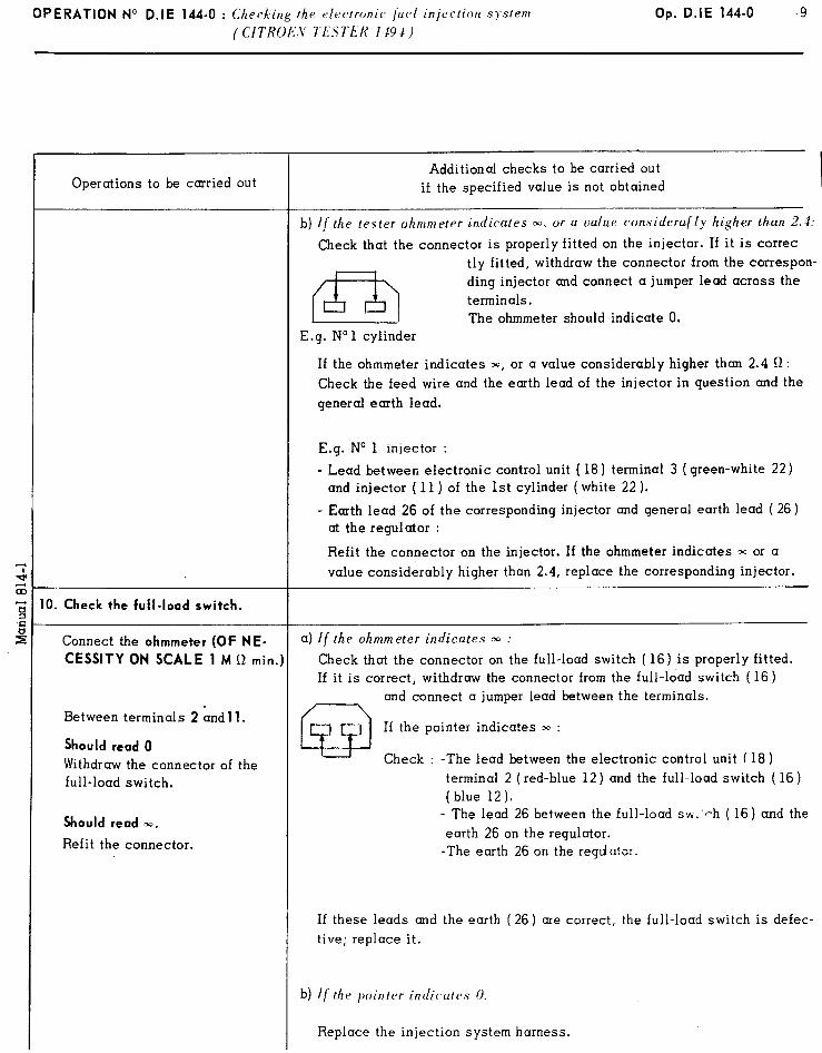
IO. Check the full-load switch.
Connect the ohmmeter (OF NE-
CESSITY ON SCALE 1 M Q min.]
Between terminals 2 hndll.
Should read 0
Withdraw the connector of the full-load switch.
Should read W.
Refit the connector.
Additional checks to be carried out if the specified value is not obtained
b) if the tester ohmmeter indicates ~1. or u value considerally higher than 2.1:
Check that the connector is properly fitted on the injector. I f it is correc tly fitted, withdraw the connector from the correspon-
m
ding injector and connect a jumper lead across the
terminals.
E.g. No 1 cylinder The ohmmeter should indicate 0.
If the ohmmeter indicates M, or a value considerably higher than 2.4 Q :
Check the feed wire and the earth lead of the injector in question and the
general earth lead.
E.g. No 1 injector :
- Lead between electronic control unit ( 18) terminal 3 ( green-white 22) and injector ( 11) of the 1st cylinder ( white 22 ).
- Earth lead 26 of the corresponding injector and general earth lead ( 26) at the regulator :
Refit the connector on the injector. I f the ohmmeter indicates m or a
value considerably higher than 2.4, replace the corresponding injector.
a) If the ohmmeter indicates 30 :
Check that the connector on the full-load switch ( 16) is properly fitted. If it is correct, withdraw the connector from the full-load switch ( 16)
and connect a jumper lead between the terminals.
I f the pointer indicates m :
Check : -The lead between the electronic control unit ( 18)
terminal 2 (red-blue 12) and the full-load switch ( 16)
(blue 12). - The lead 26 between the full-load sw.‘ph ( 16) and the
earth 26 on the regulator. -The earth 26 on the regdator.
I f these leads and the earth (26) are correct, the full-load switch is defec-
tive; replace it.
b) If the pointer indicutrs 0.
Replace the injection system harness.
OPERATION No D.IE 144-O : Checking the electronic fuel injection system ( CITROEN TESTER 1494)
Op. D.IE 144-O
Operations to be carried out Additional pecks to be carried out
if the specified valueis not obtained
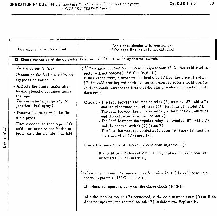
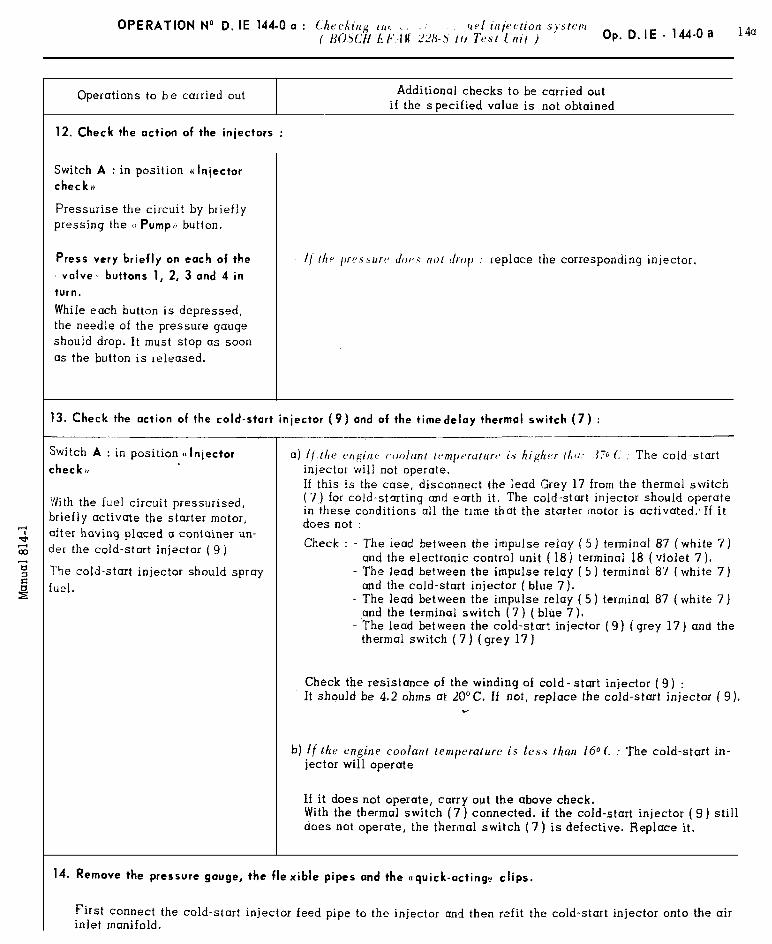
13. Check the action of the cold-start injector and of the time-delay thermol switch.
- Switch on the ignition
- Pressurise the fuel circuit by brie fly pressing button P.
- Activate the starter motor after having placed a container under the injector. The cold-start injector should
-function ( fuel-spray).
- Remove the gauge with the fle- xible pipes.
-First connect the feed pipe of the cold-start injector and fit the in- jector onto the air inlet manifold.
1) If the engine coolant temperature is higher than 370 C ( the cold-start in- jector will not operate ) ( 37’ C = 98,6 ’ F) If this is the case, disconnect the lead grey 17 from the thermal switch (7) for cold-starting and earth it. The cold-start injector should operate in these conditions for the time that the starter motor is activated. If it does not :
Check : - The lead between the impulse relay (5 ) terminal 87 ( white 7 ) and the electronic control unit ( 18) terminal 18 (violet 7).
- The lead between the impulse relay ( 5 ) terminal 87 ( white 7 ) and the cold-start injector ( violet 7 )
T The lead between the impulse relay (5) terminal 87 (white 7) and the thermal switch (7 ) ( blue 7 )
- The lead between the cold-start injector ( 9) (grey 17) and the thermal switch (7) ( grey 17)
Check the resistance of winding of cold-start injector ( 9) :
It should be 4.2 ohms at 20°C. If not, replace the cold-start in- jector ( 9 ). ( 20’ C = 68’ F)
2) If the engine coolant temperature is less than 160 C (the cold-start injec- tor will operate ). ( 16’ C = 60.8’ F )
If it does not operate, carry out the above check ( 8 13-1)
With the thermal switch (7) connected, if the cold-start injector (9) still do does not operate, the thermal switch (7) is defective. Replace it.

16 OPERATION No D.IE 144-O : Checking the electronicluel injection system (CITROEN Tester 1494)
Op. D.IE 144-O
16. Check the full-load switch (16).
Withdraw the wiring connector from the full-load switch.
Remove the full-load switch from the chassis leaving the rubber pipe on the full-load switch connected to be air-inlet manifold.
1) Start the engine. With the engine at idling speed, connect the ohmmeter (WHICH MUST BE ON SCALE
two terminals of the full-load switch.
The ohmmeter must read -
2) Stop the engine, disconnect the flexible pipe from the full-load switch.
The ohmmeter must read 0.
I f it does not, the full-load switch is defective and must be replaced.
NOTE :
1 M D minimum) to the
a) I f the flexible pipe is disconnected from the full-load switch when the engine is running at idling speed, the idling will ((hunt D due to too rich a mixture.
b) If the flexible pipe of the pressure sensor and that of the full-load switch are reversed on the inlet housing, flat-spots will appear during engine acceleration.
IMPORTANT NOTE :
The tests carried out above enable every part of the electronic fuel injection system to be checked except for
the electronic control unit itself.
If no fault is found during the tests, the electronic control unit should not yet be pronounced faulty.
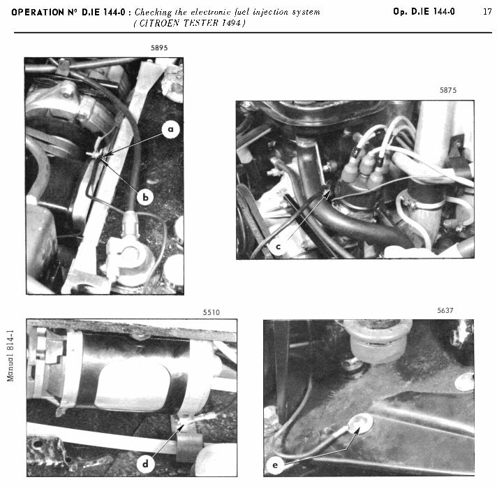
1) First check the five earth.leads careffully :
- From the voltage regulator ctarr - From the injection system harness ((b)) - From the battery ((c)r - From the electrical fuel pump ((d )r - From the car chassis ((d H
See illustration on opposite page.
Check the tightness of the bolts and pull gently on the leads to ensure that they are properly secured to their terminals.
2) Since it is difficult to check the contacts of the harness connections on the various injection system compo-
nents, it is necessary to carry out a test-run with a new wiring harness.
3) Carry out a road test. I f trouble persists, disconnect the excitation lead (yellow sleeve) from the alternator, insulate it and repeat the road-test :
I f the trouble disappears : either the alternator or the regulator is defective.. Check them and replace whichever
is faulty.
If the trouble persists : the electronic control unit is defective and must be replaced.
20 OPERATION No D.IE 144-O : ChrrXing I/ lt’ clt*ctror2ic jut>1 injection system
(CITKOI:‘~4 Tt51rr 1191)
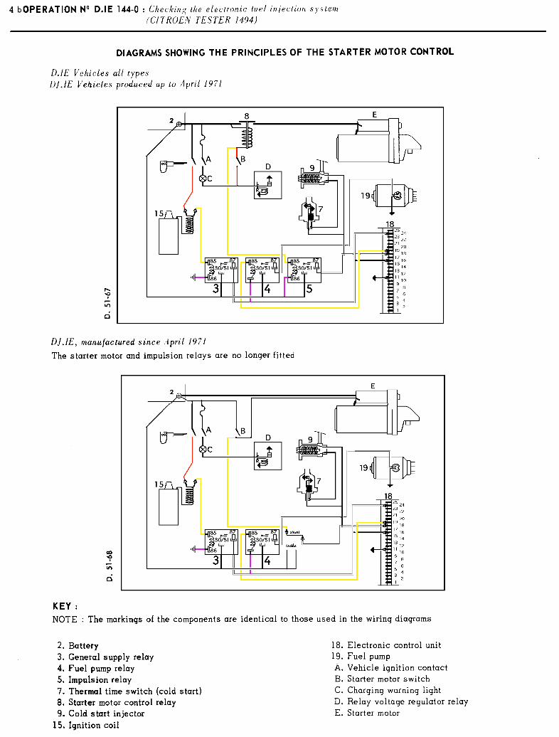
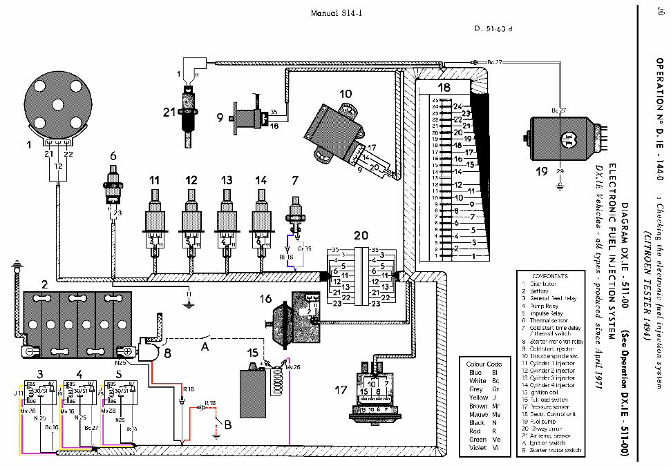
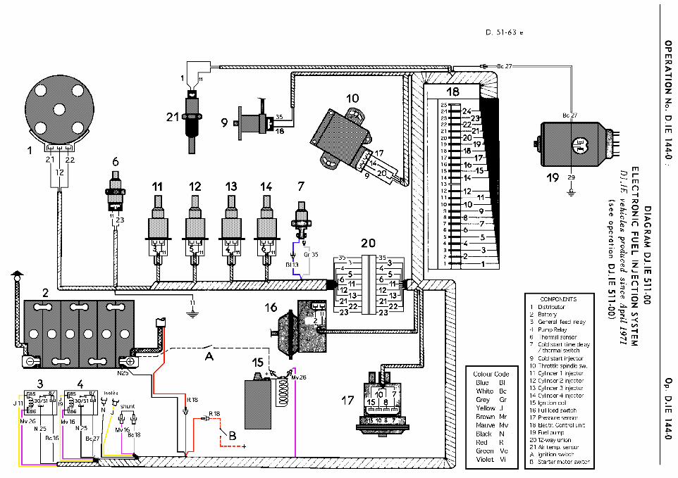
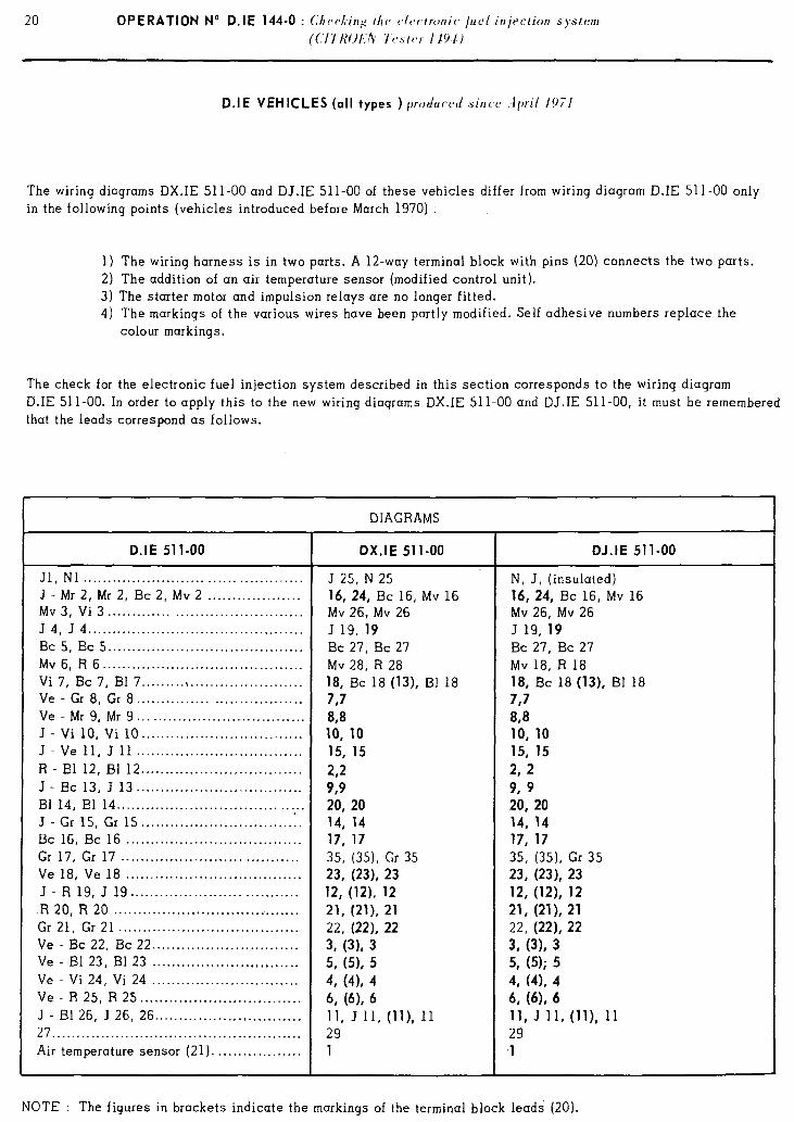
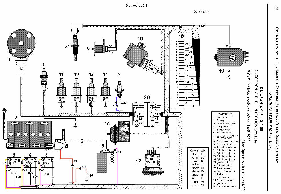
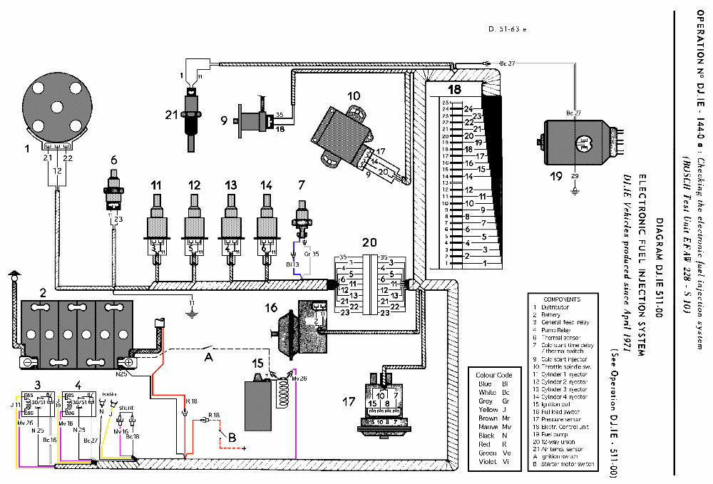
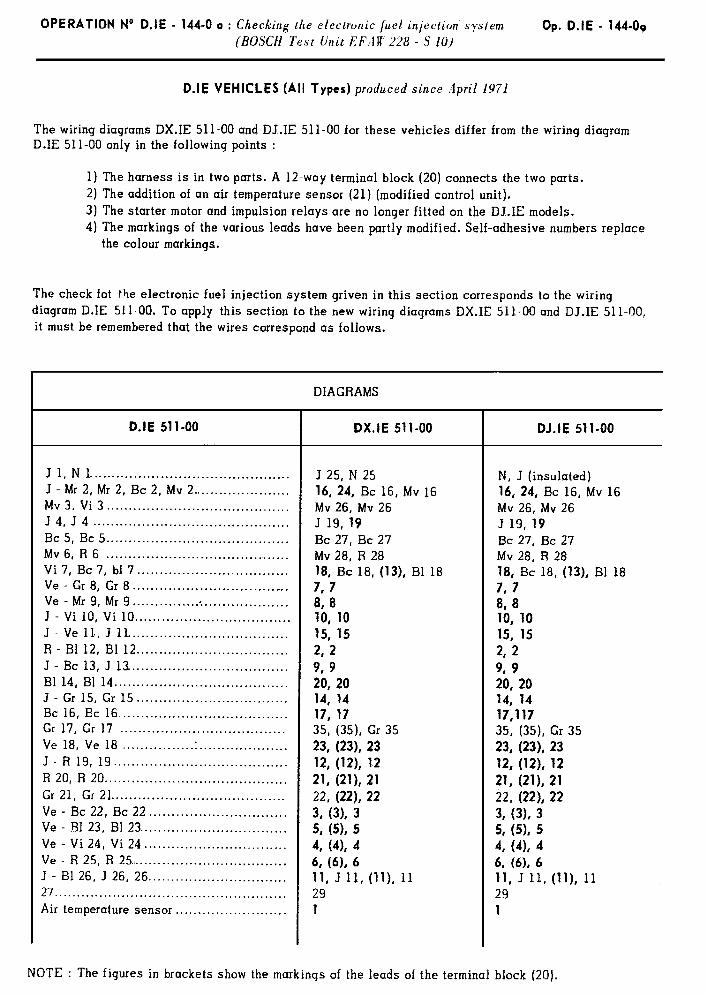
D.IE VEHICLES (all types ) ~m~ducvci since ,I/)ri/ /?i/
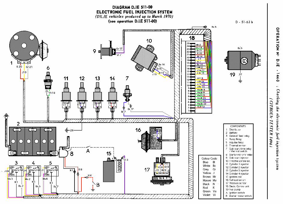
The wiring diagrams DX.IE 511-00 and DJ.IE 511-00 of these vehicles differ from wiring diagram D.IE 511-00 only in the following points (vehicles introduced before March 1970) :
1) The wiring harness is in two parts. A 12-way terminal block with pins (20) connects the two parts. 2) The addition of an air temperature sensor (modified control unit). 3) The starter motor and impulsion relays are no longer fitted. 4) The markings of the various wires have been partly modified. Self adhesive numbers replace the
colour markings.
The check for the electronic fuel injection system described in this section corresponds to the wiring diagram D.IE 511-00. In order to apply this to the new wiring diagrams DX.IE 511-00 and DJ.IE 511-00, it must be remembered
that the leads correspond as follows.
DIAGRAMS
D.IE 511-00 DX.IE 511-00 DJ.IE 511-00
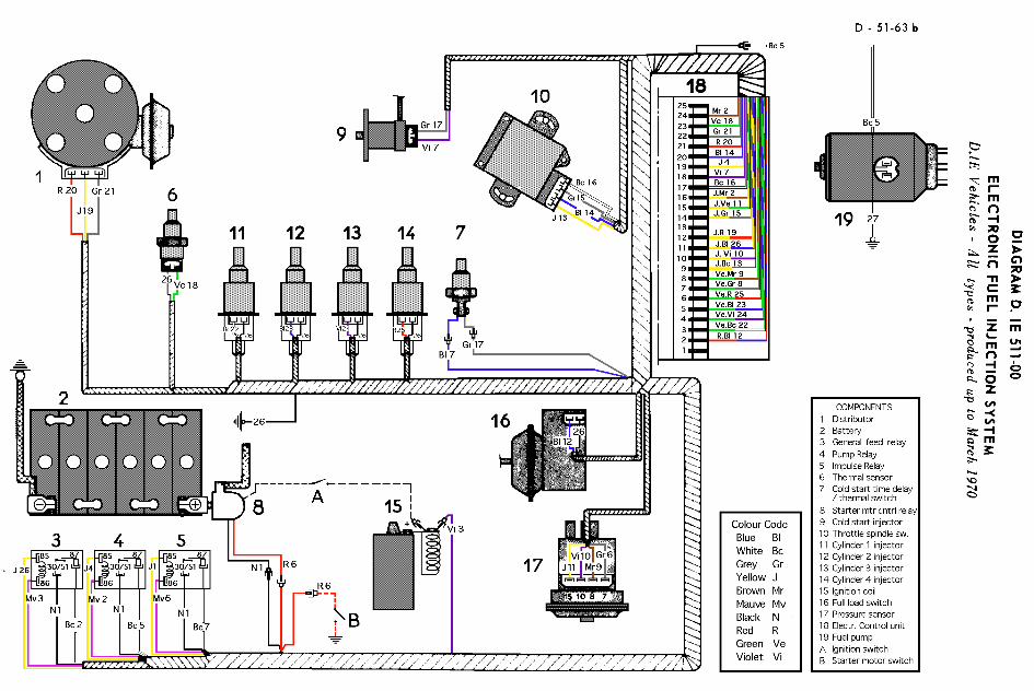
Jl, Nl ............................................ J 25, N 25 N, J, (insulated) J - Mr 2, Mr 2, Bc 2, Mv 2 ................... 16, 24, Bc 16, Mv 16 16, 24, Bc 16, Mv 16 Mv 3, Vi 3 ............. .......................... Mv 26, Mv 26 Mv 26, Mv 26 J 4, J 4 ............................................ J 19, 19 J 19, 19 Bc 5, Bc 5.. ...................................... Bc 27, Bc 27 Bc 27, Bc 27 Mv 6, R 6.. ....................................... Mv 28, R 28 Mv 18, R 18 Vi 7, Bc 7, Bl 7.. ..... .,:. ...................... 18, Bc 18 (13), Bl 18 18, Bc 18 (13), Bl 18 Ve - Gr 8, Gr 8.. ............................... 7,7 787 Ve - Mr 9, Mr 9.. ................................ 8,8 8,8 J - Vi 10, Vi 10.. ............................... 10, 10 10, 10 J - Ve 11, J 11 .................................. 15, 15 15, 15 R - Bl 12, Bl 12. ................................ 22 2, 2 J - Bc 13, J 13.. ................................ 9,9 9, 9 Bl 14, El 14.. .................................... 20, 20 20, 20 J - Gr 15, Gr 15 ............................... . . 14,14 14,14 Bc 16, Bc 16 .................................... 17, 17 17, 17 Gr 17, Gr 17 .................................... 35, (35), Gr 35 35, (35), Gr 35 Ve 18, Ve 18 .................................... 23, (231, 23 23, (23), 23 J - R 19, J 19.. ................................ 12, (12). 12 12, (12), 12 R 20, R 20 ...................................... 21,(21), 21 21, (21), 21 Gr 21, Gr 21 ..................................... 22, (221, 22 22, (22), 22 Ve - Bc 22, Bc 22.. ............................ 3, (3), 3 3, (31, 3 Ve - Bl 23, Bl 23 .............................. 5, (51, 5 5, (5); 5 Ve - Vi 24, Vi 24 .............................. 4, (4)s 4 4, (41, 4 Ve - R 25, R 25.. ............................... 4 (61, 6 6, b9, 6 J - Bl 26, J 26, 26.. ............................ 11, J 11, (ll), 11 11, J 11, (ll), 11 27.. ................................................. 29 29 Air temperature sensor (21). ................. 1 .l

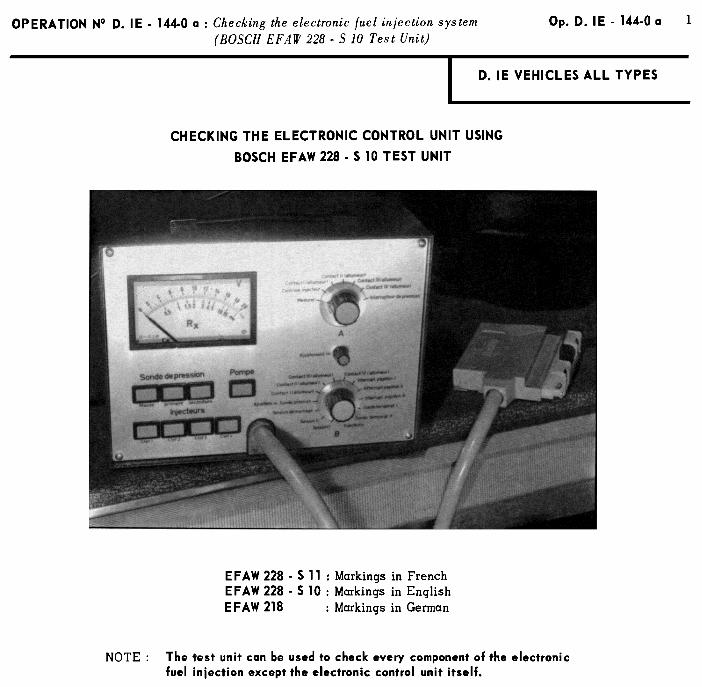
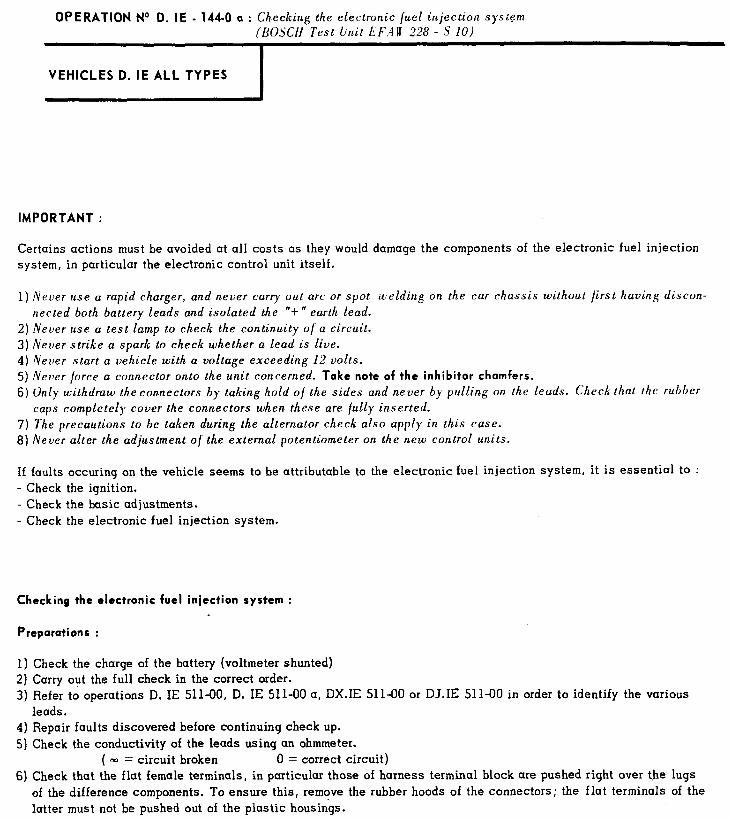
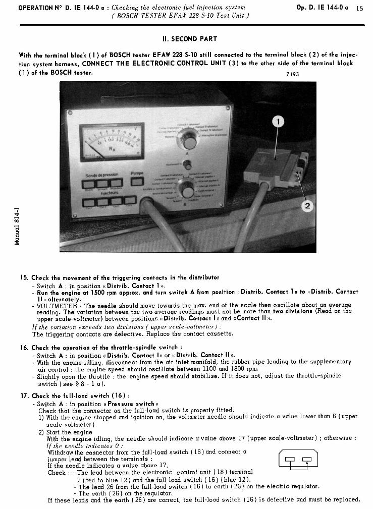
OPERATION No D. IE - 144-O a : Checking the electronic fuel injection system (BOSCH Test Unit EF.4A 228 - 5 10)
1 VEHICLES D. IE ALL TYPES
IMPORTANT :
Certains actions must be avoided at all costs as they would damage the components of the electronic fuel injection system, in particular the electronic control unit itself.
1) Never use a rapid charger, and never carry out arc or spot welding on the car chassis without first having discon- nected both battery leads and isolated the “t” earth lead.
2) Never use a test lamp to check the continuity of a circuit. 3) Never strike a spark to check whether a lead is live. 4) Never start a vehicle with a voltage exceeding 12 volts. 5) Never force a connector onto the unit concerned. Take note of the inhibitor chamfers.
6) Only withdraw the connectors by taking hold of the sides and never by pulling on the leads. Check that IMP rubber caps completely cover the connectors when these are fully inserted.
7) The precautions to be taken during the alternator check also apply in this case. 8) Never alter the adjustment of the external potentiometer on the new control units.
I f faults occuring on the vehicle seems to be attributable to the electronic fuel injection system, it is essential to : - Check the ignition. - Check the basic adjustments. - Check the electronic fuel injection system.
Checking the electronic fuel iniection system :
Preparations :
1) Check the charge of the battery (voltmeter shunted)
2) Carry out the full check in the correct order. 3) Refer to operations D. IE 511-00, D. IE 511-00 a, DX.IE 511-00 or DJ.IE 511-00 in order to identify the various
leads. 4) Repair faults discovered before continuing check up.
5) Check the conductivity of the leads using an ohmmeter. ( m = circuit broken 0 = correct circuit)
6) Check that the flat female terminals, in particular those of harness terminal block are pushed right over the lugs
of the difference components. To ensure this, remove the rubber hoods of the connectors; the flat terminals of the latter must not be pushed out of the plastic housin&.
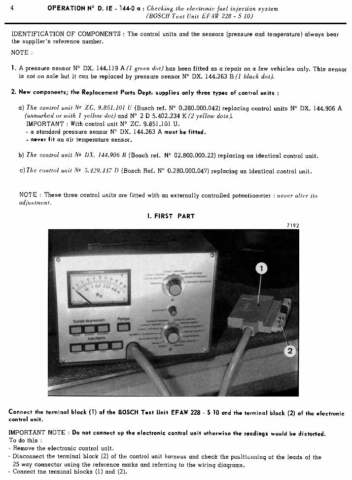
OPERATION No D. lE - 144-O a : Checking the electronic /uel injection system (&XCH Test l&t EF:IR 228 - S IO)
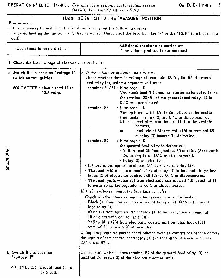
TURN THE SWITCH TO THE “MEASURE” POSITION
Precautions :
Op. D.IE-144-0 a 5
- It is necessary to switch on the ignition to carry out the following checks. - To avoid heating the ignition coil, disconnect it. (Disconnect the lead from the ‘I-’ or the “RUP” terminal on the
coil).
Operations to be carried out Additional checks to be carried out if the value specified is not obtained
1. Check the feed voltage of electronic control unit.
a) Switch B : in position “voltage 1”
Switch on the ignition
VOLTMETER : should read 11 to 12.5 volts.
4 m
b) Switch 6 : in position “voltage II”
VOLTMETER : should read 11 to 12.5 volts
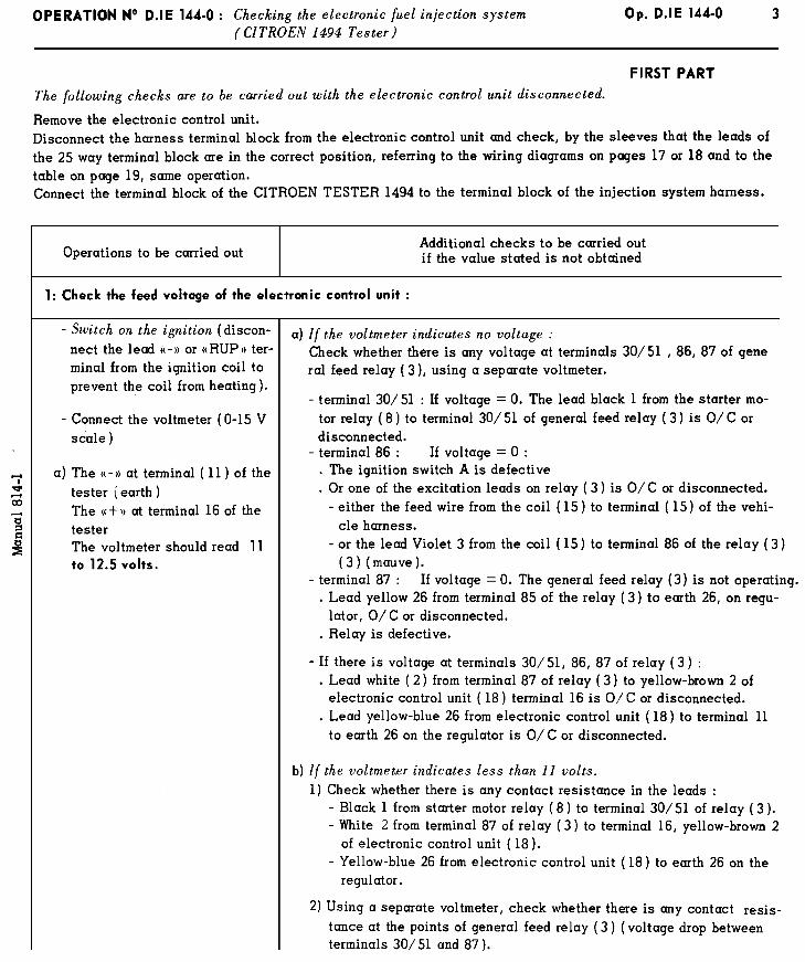
If the voltmeter indicates no voltage : Check whether there is voltage at terminals 30/51, 86, 87 of general feed relay (3), using a separate voltmeter - terminal 30/51 : if voltage = 0
The black lead N 1 from the starter motor relay (8) to the terminal 30/51 of the general feed relay (3) is O/C or disconnected.
- terminal 86 : if voltage = 0 The ignition switch (A) is defective, or the excita- tion leads on relay (3) sre O/C or disconnected. Either : feed wire from the coil (15) to the vehicle
harness, or lead (violet 3) from coil (15) to terminal 86
of relay (3) (mauve 3), defective. - terminsl 87 : if voltage = 0
the general feed relay is defective : - Yellow lead 26 from terminal 85 or relay (3) to earth
26, on regulator, O/C or disconnected. - Relay (3) is defective.
- If there is voltage at terminals 30/51, 86, 87 of relay (3) : - The lead (white 2) from terminal 87 of relay (3) to terminal 16 (yellow
brown 2) of electronic control unit (18) is O/C or disconnected. - The lead (yelIow-blue 26) from electronic control unit (18) terminal 11
to earth 26 on the regulator is O/C or disconnected. I! the voltmeter indicates less than 11 volts :
Check whether there is any contact resistance in the leads : - Black (1) from starter motor relay (8) to terminul 30/51 of general
feed relay (3). - White (2) from terminal 87 of relay (3) to yellow-brown 2, terminal
16 of electronic control unit (18). - Yellow-blue (26) from electronic control unit terminal block (18)
terminal 11 to earth 26 at regulator.
ing a separate voltmeter check wheter there is contact resistance across : points of the general feed relay (3) (voltage drop between terminals /51 und 87) .
reck lead (white 2) from terminal 87 of the general feed relay (3) to :minal 24 (brown 2) of the electronic control unit.
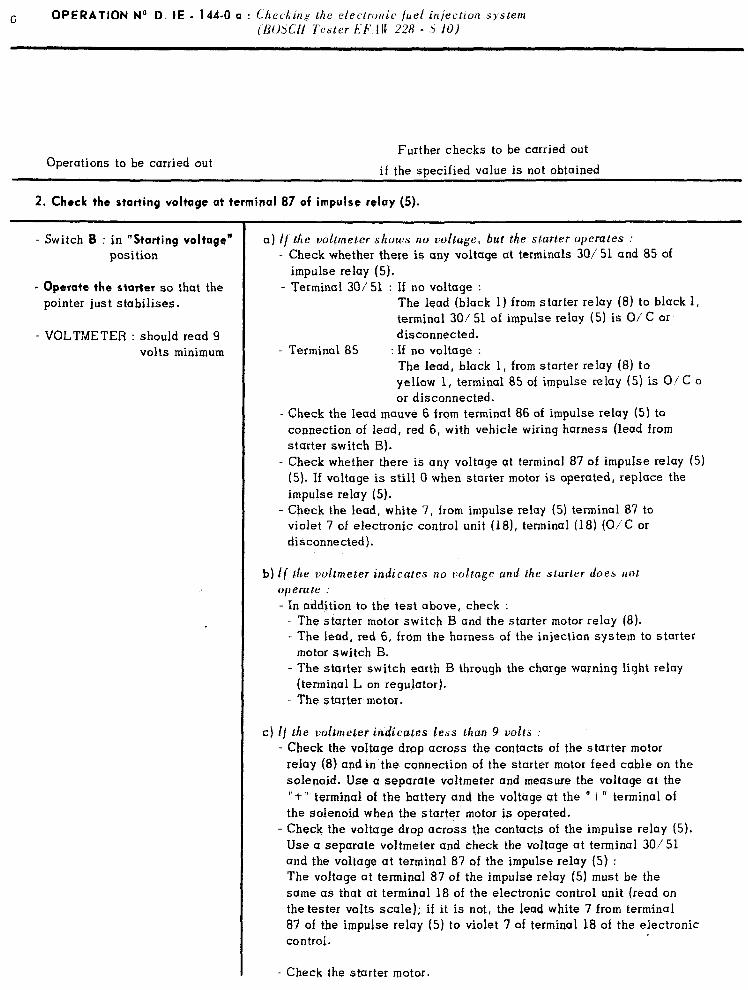
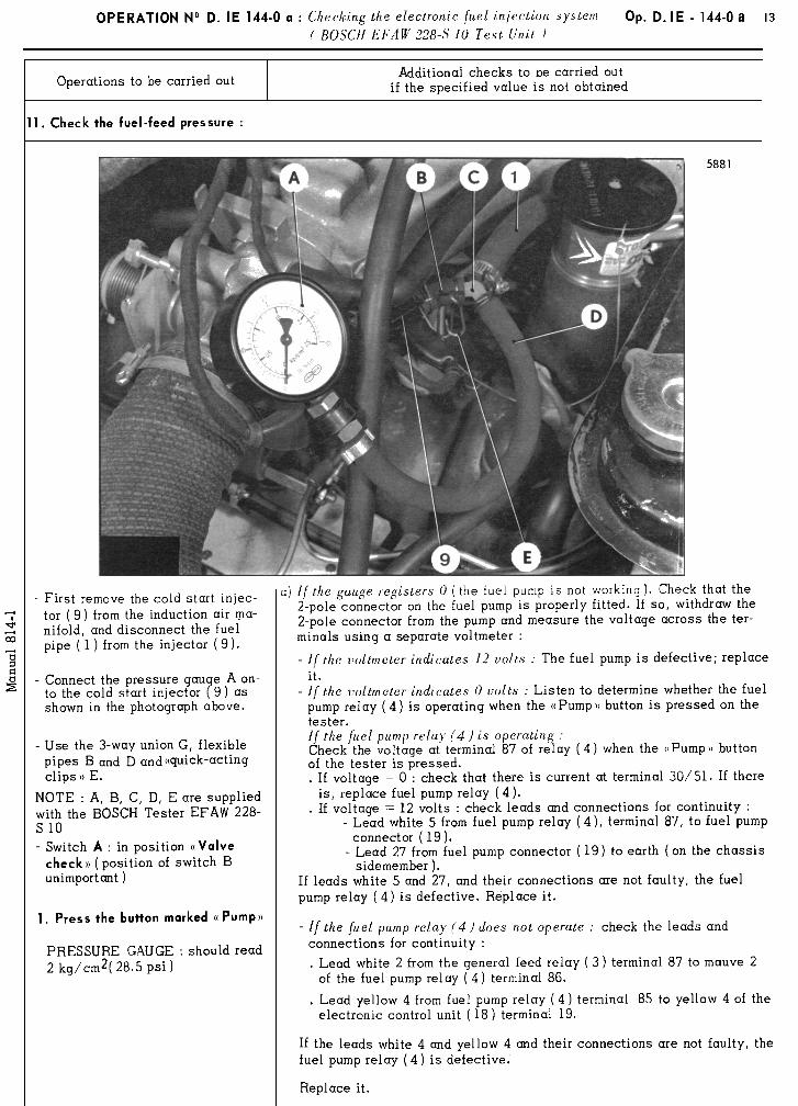
6 OPERATION No D. tE - 144-O a : ChecXirzg the electronic fuel injecticm system (LOCH Tester kF.lR 228 - .5 IO)
Operations to be carried out Further checks to be carried out
if the specified value is not obtained
2. Check the starting voltage at terminal 87 of impulse relay (5).
- Switch B : in “Starting voltage”
position
- Operate the starter so that the pointer just stabilises.
- VOLTMETER : should read 9 volts minimum
a) if the voltmeter shows no voltage, but the starter operates : - Check whether there is any voltage at terminals 30/ 51 and 85 of
impulse relay (5). - Terminal 30/51 : If no voltage :
The lead (black 1) from starter relay (8) to black 1, terminal 30i 51 of impulse relay (5) is O/ C or disconnected.
- Terminal 85 : If no voltage : The lead, black 1, from starter relay (8) to yellow 1, terminal a5 of impulse relay (5) is O/C 0 or disconnected.
- Check the lead mauve 6 from terminal 86 of impulse relay (5) to connection of lead, red 6, with vehicle wiring harness (lead from starter switch B).
- Check whether there is any voltage at terminal 87 of impulse relay (5) (5). If voltage is still 0 when starter motor is operated, replace the impulse relay (5).
- Check the lead, white 7, from impulse relay (5) terminal 87 to violet 7 of electronic control unit (la), terminal (ia) (O/C or disconnected).
b) lf the witmeter indicates no robrage and the starter does not operate :
- In addition to the test above, check : - The starter motor switch B and the starter motor relay (8). - The lead, red 6, from the harness of the injection system to starter
t relay motor switch B.
- The starter switch earth B through the charge warning ligh (terminal L on regulator).
- The starter motor.
c) f{ the voltmeter indicates less than 9 volts : - Check the voltage drop across the contacts of the starter motor
relay (8) andin the connection of the starter motor feed cable on the solenoid. Use a separate voltmeter and measure the voltage at the I’+” terminal of the battery and the voltage at the “frr terminal of the solenoid when the starter motor is operated.
- Check the voltage drop across the contacts of the impulse relay (5). Use a separate voltmeter and check the voltage at terminal 3Oi51 and the voltage at terminal 87 of the impulse relay (5) : The voltage at terminal 87 of the impulse relay (5) must be the same as that at terminal 18 of the electronic control unit (read on the tester volts scale); if it is not, the lead white 7 from terminal 87 of the impulse relay (5) to violet 7 of terminal 18 of the electronic control.
- Check the starter motor.
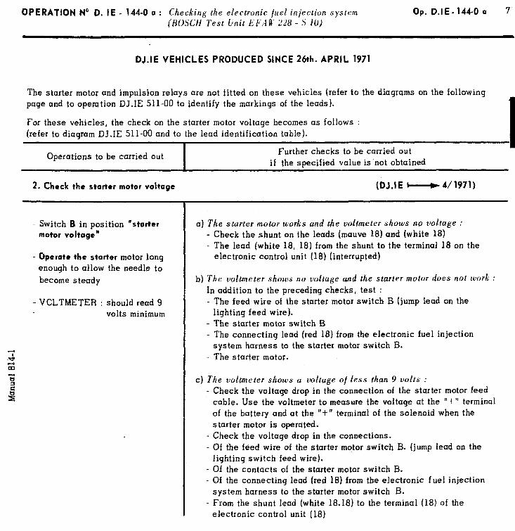
OPERATION No D. IE - 144-O a : Checking the electronic {uel injection system Op. D.IE-144-O a 7
(BOSCH Test Unit EFAR’ 228 - S JO)
DJ.IE VEHICLES PRODUCED SINCE 26th. APRIL 1971
The starter motor and impulsion relay page and to operation DJ.IE 511-00 tc
For these vehicles, the check on the (refer to diagram DJ.IE 511-00 and to
Operations to be carried out
2. Check the starter motor voltage
- Switch B in position “starter
motor voltage”
- Operate the starter motor long enough to allow the needle to become steady
- VCLTMETER : should read 9 volts minimum
r are not fitted on these vehicles (refer to the diagrams on the following identify the markings of the leads).
starter motor voltage becomes as follows : the lead identification table).
Further checks to be curried out I
if the specified value is’not obtained
(DJ.IE M 4/1971)
a) The starter motor works and the voltmeter shows no voltage : - Check the shunt on the leads (mauve 18) and (white 18) - The lead (white 18, 18) from the shunt to the terminal 18 on the
electronic control unit (18) (interrupted)
b) The voltmeter shows no voltage and the starter motor does not work : In addition to the preceding checks, test : - The feed wire of the starter motor switch B (jump lead on the
lighting feed wire). - The starter motor switch B - The connecting lead (red 18) from the electronic fuel injection
system harness to the starter motor switch B. - The starter motor.
c) The voltmeter shows a voltage 01 less than 9 volts : - Check the voltage drop in the connection of the starter motor feed
cable. Use the voltmeter to measure the voltage at the ‘+” terminal of the battery and at the “t” terminal of the solenoid when the starter motor is operuted.
- Check the voltage drop in the connections. - Of the feed wire of the starter motor switch B. (jump lead on the
lighting switch feed wire). - Of the contacts of the starter motor switch B. - Of the connecting lead (red 18) from the electronic
system harness to the starter motor switch B. - From the shunt lead (white 18.18) to the terminal (1
electronic control unit (18)
fuel injection
8) of the
10 OPERATION No D. IE 144-O a : Cht:c,king tht: electronir jnel injec.lir/tl +tem
( I~OSCII 7‘e.sler I,./- 1 U 22% ,i 10)
T)peratior.s to be carried out Additional checks to be carried out if the specified value is not obtained
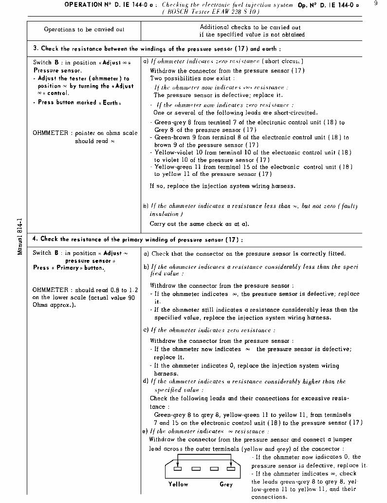
5. Check resistance of secondary winding of pressure sensor (17) :
Switch I3 : in position (( Adjust r
pressure sensor )t
Press (( Secondary)) button
OHMMETER : should read 3 to 4 on the Rx scale ( 350 ohms approx. )
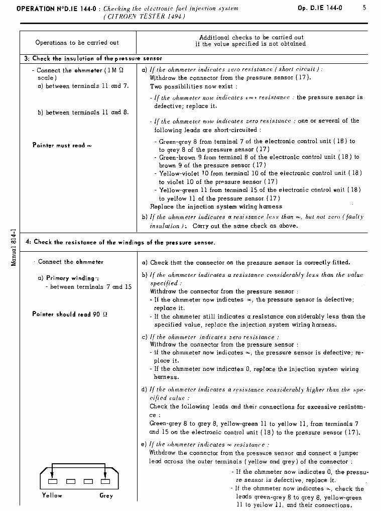
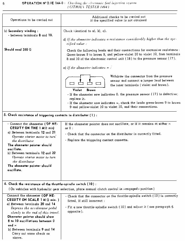
- Checks identical to 4 a), b), c). d) If the ohmmctc,r indicatras rt rr*sistunct’ con.sidrrub/). highvr thtrrr Ihe
,sper*ifieti value :
Check the following leads and their connections for excessive resistant I
: Green-brown 9 to brown 9, and yellow-violet 10 to violet 10, from termin 1 8 and 10 of the electronic control unit ( 18) to the pressure sensor ( 17)
e) I[ the ohmmeter indicates 13 Withdraw the connector from the pressure sensor and connect a jumper 1 lead between the inner terminals (violet and brown).
f=G=-~
- If the ohmmeter now indicates 0, the pres- sure sensor (17) is defective. Replace it.
- If the ohmmeter now indicates *, check
Violet Brown the leads green-brown 9 to brown 9 and ye]-- low-violet 10 to violet 10, and their connec- tions.
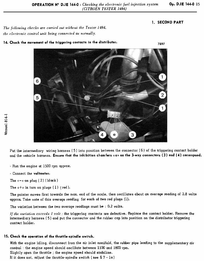
6. Check resistance of triggering contacts in distributor (1) .
-
1
2
) Switch B : in position (( Distrib.
contact 10
Operate starter motor to turn distributor
.
OHMMETER : the pointer should oscillate.
‘) Switch B: in position G Distrib.
Contact II ))
Carry out same check as above (86-l)
If the ohmmeter pointer does not oscillate, or if it remains at either x or 0
- Check that the connector on the distributor is correctly fitted.
- Replace the triqgertng contact cassette.
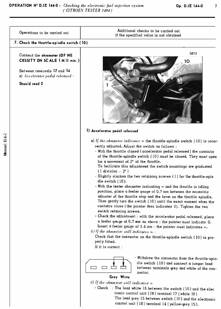
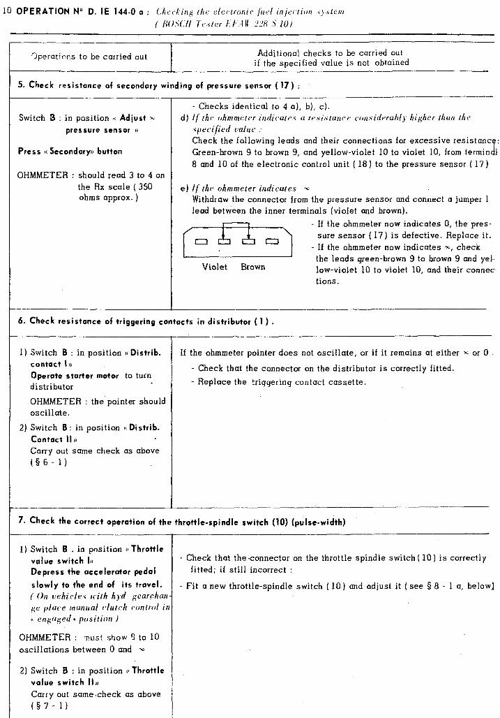
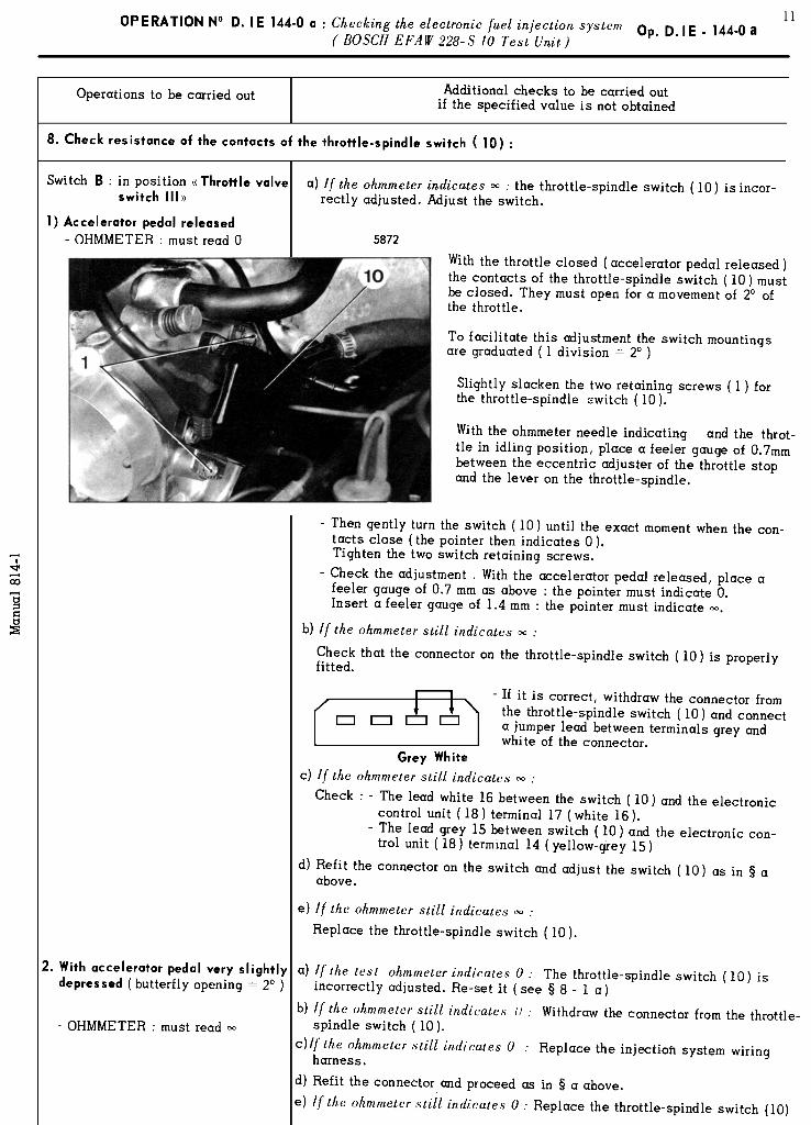
7. Check the correct operation of the throttle-spindle switch (10) (pulse-width)
I 1) Switch B . in position ((Throttle
value switch 1,)
Qepress the accelerator pedal
- Check that the connector on the throttle-spindle switch ( 10) is correctly fitted; if still incorrect :
slowly to the end of its travel. I - Fit a new throttle-spindle switch ( 10) and adjust it (see 9 8 - 1 a, below]
( On vehicles with hyd gear.chan ge place manuul clutch wntroi in (t cngclged I) position )
OHMMETER : Tust show ‘: to 10 oscillations between 0 and x
2) Switch B : in position u Throttle
value switch 11~
Carry out samecheck as above (§7- 1)
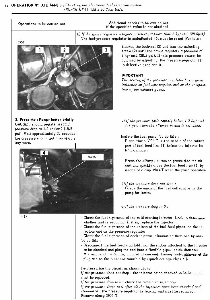
12 OPERATION No D. IE 144-O a : Checking the electronic fuel injection system (BOSCH EFliD 228-S 10 Test Unit I
Operations to be carried out Additional checks to be carried out
if the specified value is not obtained
9. Check the resistance of the thermal sensor (6) :
- OHMMETER : must read 0.3 to 2. on Rx scale ( 2500 Ohms approx. at 2o” c )
NOTE : The specified value, of 2500 Ohms corresponds ,to 20°C. At a higher temperature resistance is lower.
I
a) If the ohmmeter indicates ~0 : Check that the connector is properly fitted to the thermal sensor. If it is correct, withdraw the connector from the thermal sensor ( 6). and connect lead green 18 to earth. - If the ohmmeter indicates 0, check the lead 26 between the thermal sen.
sot ( 6) and earth on the regulator. - If it is correct,‘replace the thermal sensor (6 ). - If the ohmmeter indicates =, check the lead, green 18 to green 18, bet-
ween terminal 23 on the electronic control unit ( 18 ) and the thermal sensor ( 6),
b) If the ohmmeter indicates 0 : Withdraw the connector from the thermal sensor (6 ). - If the ohmmeter indicates 0, check the lead, green 18 to green 18, bet-
ween terminal 23 of the electronic control unit and the thermal sensor (SD - If the ohmmeter indicates m, replace the thermal sensor ( 6 ).
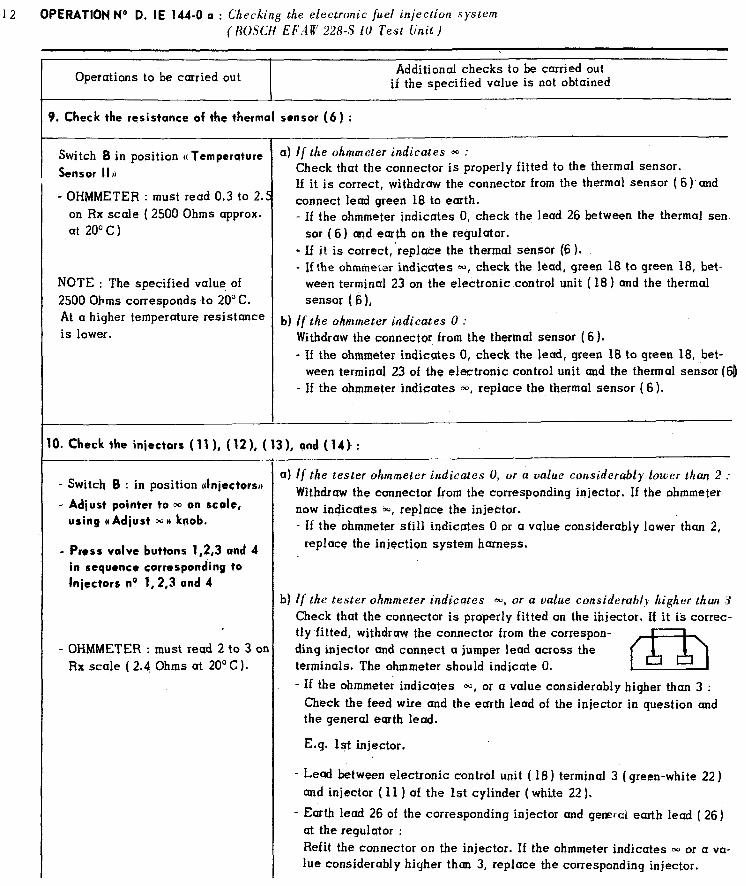
1. Check the injectors ( 111, ( 12 1, ( 13 1, and ( 14) :
- Switch B : in position Jnjectors,)
- Adjust pointer to m on scale,
using (( Adiust m n knob.
- Press valve buttons 1,2,3 and 4
in sequence corresponding to
Injectors no 1,2,3 and 4
- OHMMETER : must read 2 to 3 or Rx scale ( 2.4 Ohms at 20’ C ).
a) If the tester ohmmeter iRd&ates 0, or a value considerably lower than 2 :
Withdraw the connector from the corresponding injector. If the ohmmeter now indicates 00, replace the injector. - If the ohmmeter still indicates 0 or a value considerably lower. than 2,
replace the injection system harness.
b) If the tester ohmmeter indicates m, or a value considerahl!- higher than 3
Check that the connector is properly fitted on the ihjector. If it is correc- tly fitted, withdraw the connector from the correspon- ding injector and connect a jumper lead across the terminals. The ohmmeter should indicate 0. m
- If the ohmmeter indicates m, or a value considerably higher than 3 : Check the feed wire and the ecrrth lead of the injector in question and the general earth lead.
E.g. 1st injector.
- Lead between electronic control unit ( 18) terminal 3’( green-white 22) and injector ( 11 ) of the 1st cylinder (white 22).
- Earth lead 26 of the corresponding injector and general earth lead ( 26) at the regulator : Refit the connector on the injector. If the ohmmeter indicates m or a va- lue considerably higher than 3, replace the corresponding injector.
OPERATION No D. IE - 144-O a : Checking the electronic fuel injection system Op. 0. IE . 1444 8 k2 a (BOSCH Test Unit EFrlW 228 - S IO)
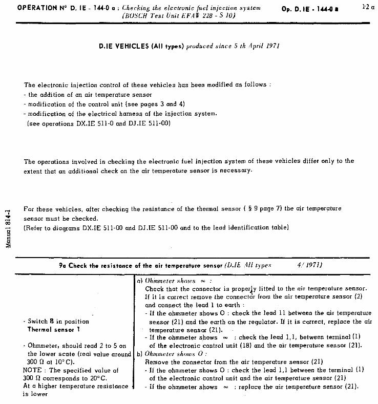
D.IE VEHICLES (All types) produced since 5 th April 1971
The electronic injection control of these vehicles has been modified as follows :
- the addition of an air temperature sensor
- modification of the control unit (see pages 3 and 4) - modification of the electrical harness of the injection system.
(see operations DX.IE 511-O and DJ.IE 511-00)
The operations involved in checking the electronic fuel injection system of these vehicles differ only to the
extent that an additional check on the air temperature sensor is necessary.
T: For these vehicles, after checking the resistance of the thermal sensor ( 8 9 page 7) the air temperpture
2 sensor must be checked.
‘E; (Refer to diagrams DX.IE 511-00 and DJ.IE 511-00 and to the lead identification table) 1
3a Check the resistance of the air tempercrture sensor (D.lE All types 4/ 1971)
- Switch 8 in position Thermal sensor 1
- Ohmmeter, should read 2 to 5 on the lower state (real value around 300 Q at 10°C).
NOTE : The specified value of 300 Q corresponds to 2O’C. At a higher temperature resistance is lower
a) Ohmmeter shows - : Check that the connector is properly fitted to the air temperature sensor. If it is correct remove the connector from the air temperature sensor (2) and connect the lead 1 to earth : - If the ohmmeter shows 0 : check the lead 11 between the air temperature
sensor (21) and the earth on the regulator. If it is correct, replace the air temperature sensor (21).
- If the ohmmeter shows 00 : check the lead l,l, between terminal (I) of the electronic control unit (18) and the air temperature sensor (21).
b) Ohmmeter shows 0 : Remove the connector from the air temperature sensor (21) - If the ohmmeter shows 0 : check the lead 1,l between the terminal (1)
of the electronic control unit and the air temperature sensor (21) - If tbe ohmmeter shows 00 : replace the air temperature sensor (21).

3) Snap open the throttle : the needle must mc 7 e smartly between the two values indicated previously. I[ the needle onl). drops slowl~~ :
- Disconnect from the air inlet manifold the flexible pipe leading to the switch ( 16) :
The engine idling should become ((jumpy)) (mixture too rich).
If it does not, replace the full-load switch.
18. Switch off the ignition
Remove the BOSCH TESTER EFAW 228 S-10.
Refit the electronic control unit.
III. FART THREE
IMPORTANT NOTE :
The BOSCH TESTER EFAW 228 S-10 enables every part of the electronic fuel injection system to be checked ex-
cept for the electronic control unit itself.
If no fault is found during the tests, the electronic control unit should not yet be pronounced faulty :
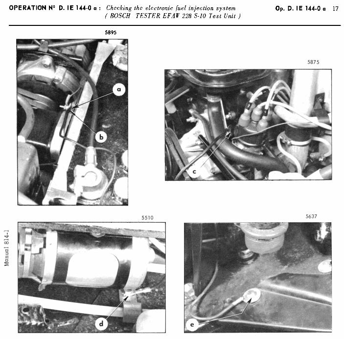
1) First check the five earth leads carefully :
- From the voltage regulator (a)
- From the injection system harness ( b)
- From the battery ( c)
- From the electrical fuel pump (d)
- From the car chassis ( e )
See illustrations on page 17.
Check the tightness of the bolts and pull gently on the leads to ensure that they are properly secured to their terminals.
2) Due to the difficulty of checking the contacts of the wiring harness terminals on the various components of
the electronic injection system, a new wiring harness must be tried.
3) Carry out a road test. If the trouble persists disconnect the excitation lead (yellow sleeve) from the alternator, insulate it, and repeat the road-test :
II the ~rouIJc~ tliruppcurs : either the alternator or the regulator is defective. Check them and replace whichever is faulty.
I/ thc~ trtrrclrlt~ fjrrrbi>ts : the electronic control unit is defective and must be replaced.
OPERATION No D.lE - 144-Oa : Checking the electronic fuel injection system Op.D.IE - l44-Oa 19 (BOSCHI EFA rt’ 228 S ld Test Unit)
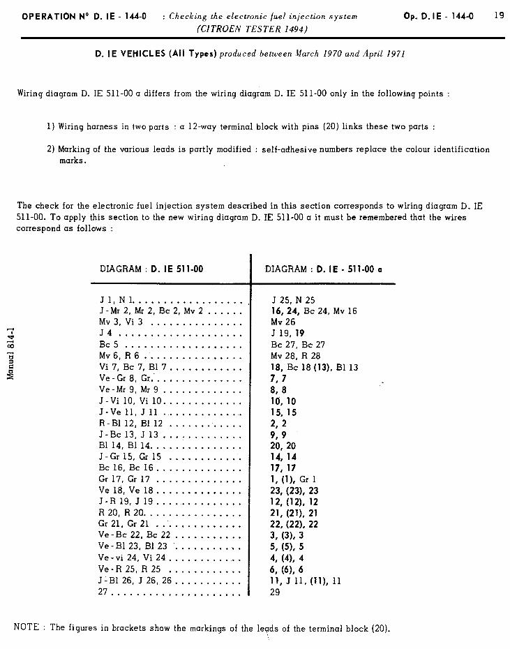
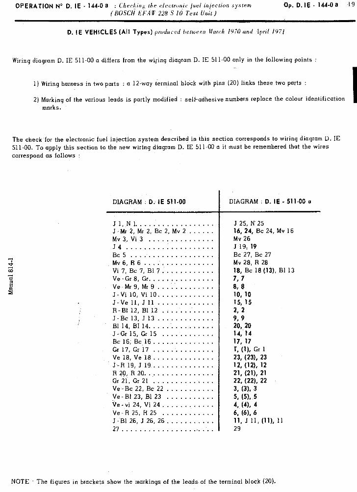
D. IE VEHICLES (All Types) pxdured between Ilarch 1970 and April 1971
Wiring diagram D. IE 511-00 a differs from the wiling diagram D. IE 511-00 only in the following points :
1) Wiring harness in two parts : a 12-way terminal block with pins (20) links these two parts :
2) Marking of the various leads is partly modified : self-adhesive numbers replace the colour identification I marks.
The check for the electronic fuel injection system described in this section corresponds to wiring diagram D. IE 511-00. To a,pply this section to the new wiring diagram D. IE 511-00 a it must be remembered that the wires correspond as follows :
DIAGRAM : 0. I E 51 l-00 I
DIAGRAM : 0. IE - 511-00 a
Jl.Nl.................. J-Mr2,Mr2,Bc2,Mv2.. .... Mv3,Vi3 ............... J4 .................... Bc5.. ................. Mv6.R6 ................ Vi 7, Bc 7, B17. ........... Ve-Gr8, Gr ............... Ve-Mr9,Mr9.. ........... J-Vi 10, Vi 10 ............. J-Ve 11, J 11 ............. R-81 12, Bl 12 ............ J-Bc 13, J 13 ............. Bl 14, Bl 14. .............. J-Gr 15, Gr 15 ............ Bc 16, Bc 16 .............. Gr 17, Gr 17 .............. Ve 18, Ve 18 .............. J-R19,J19.. ............ R20,R20 ................ Gr 21, Gr 21 .............. Ve-Bc 22, Bc 22 ........... Ve-B123, B123 ........... .~, Qe-vi 24, Vi 24. ........... Ve-R25,R25 ............ J-B1 26, J 26, 26 ........... 27 ................ .r. ...
J 25, N 25 16,24, Bc 24, Mv 16 Mv 26 J 19, 19 Bc 27, Bc 27 Mv 28, R 28 18, Bc 18(13), Bl 13 7, 7 8, 8 10,lO l&15 2, 2 9, 9 29, 20 14,14 17, 17 r, (11, Gr 1 23, (231, 23 12, (121, 12 21, (211, 21 22, (221, 22 3, (31, 3 5, (54, 5 4, (4, 4 6, (4% 6 11‘ .J 11, (ll), 11 29
NOTE : The figures in brackets show the markings of the leads of the terminal block (20).
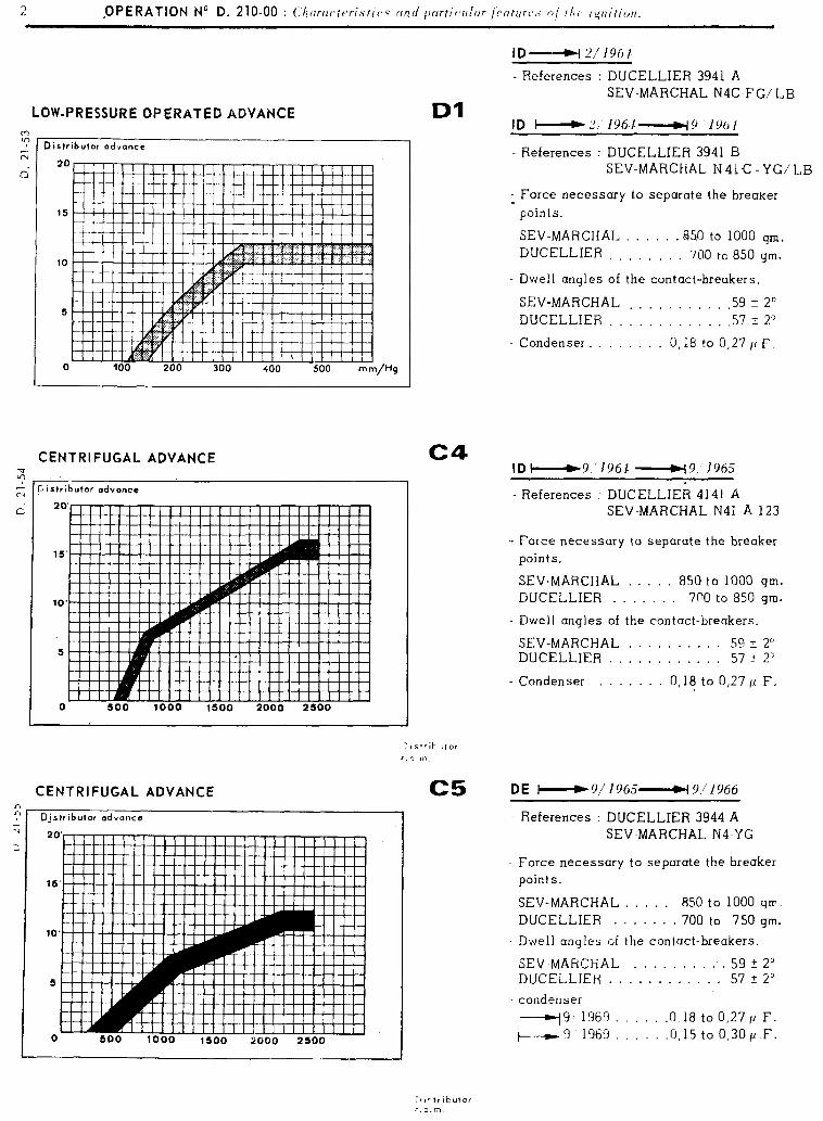
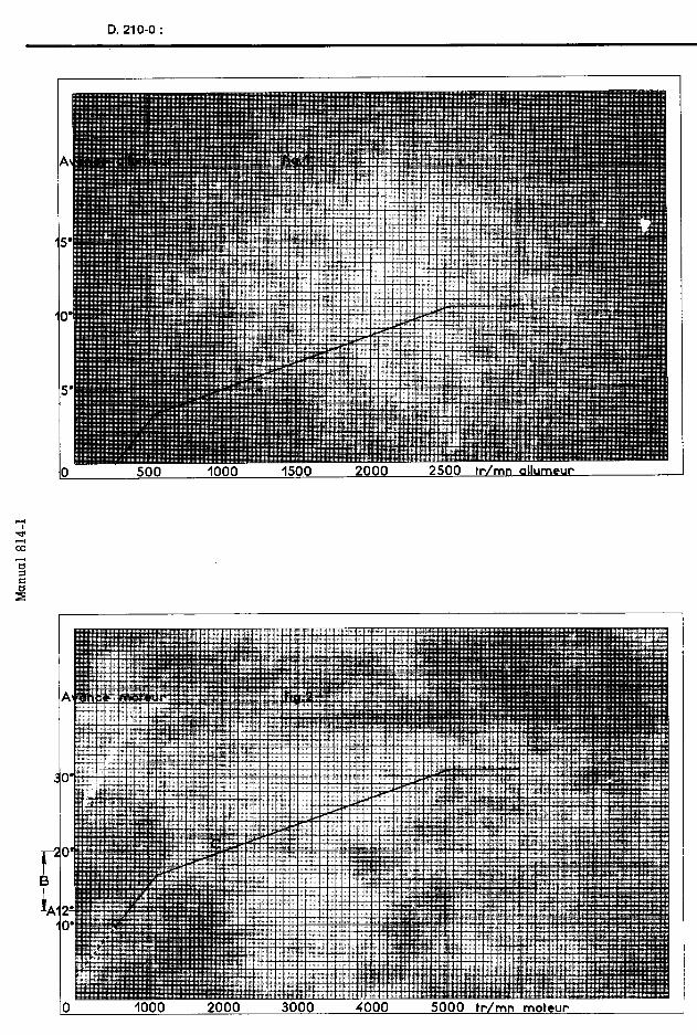
LOW-PRESSURE OPERATEC ADVANCE . ‘
z Distributor advance N
d 20
15
10
5
0 100 200 300 400 500
CENTRIFUGAL ADVANCE 2 .~ k pistributor odvanca
CENTRIFUGAL ADVANCE C5 DE W9/1965-W9,‘1966
Djstributor advance
Dl
- References : DUCELLIER 3941 A
SEV-MARCHAL NIC-FG/ LB
References : DUCELLIER 3941 B SEV-MARCHAL N 41 C - YG,‘LB
- Force necessary to separate the breaker
points.
SEV-MARCHAL . . . .85.0 to 1000 gm,
DUCELLIER . . . 700 tc 850 gm.
- Dwell angles of the contact-breakers.
SEV-MARCHAL . . . . . . . .59 + 2O DUCELLIER . . . . . . . . . .57 t 2”
Condenser. . . 0,18 to 0,27 1~ F.
c4 ID -9 1961 -w9’ 1965
References : DUCELLIER 4141 A SEV-MARCHAL N41 A 123
- Force necessary to separate the breaker points.
SEV-MARCHAL . . . . 850 to 1000 gm. DUCELLIER . . . . . . 7nO to 850 gm.
- Dwell angles of the contact-breakers.
SEV-MARCHAL .......... 59 + 2” DUCELLIER ............ 57 2 2’
- Condenser . . . . 0, lf to 0,27 11 F.
- References : DUCELLIER 3944 A SEV-MARCHAL N4-YG
Force necessary to sepurate the breaker points.
SEV-MARCHAL . . . . . 850 to 1000 glr DUCELLIER . . . . . . 700 to 750 gm.
- Dwell angles of the contact-breakers.
SEV MARCHAL . . . . . . . :. 59 -t 2’ DUCELLIER . v e . . . . . . . . 57 2 2’
- condenser --9, 1969 . .I?,18 to 0,271’ F. +---m-9 1969 .0,15 to 0,30/l F.
;‘li-tributor r.p.m.
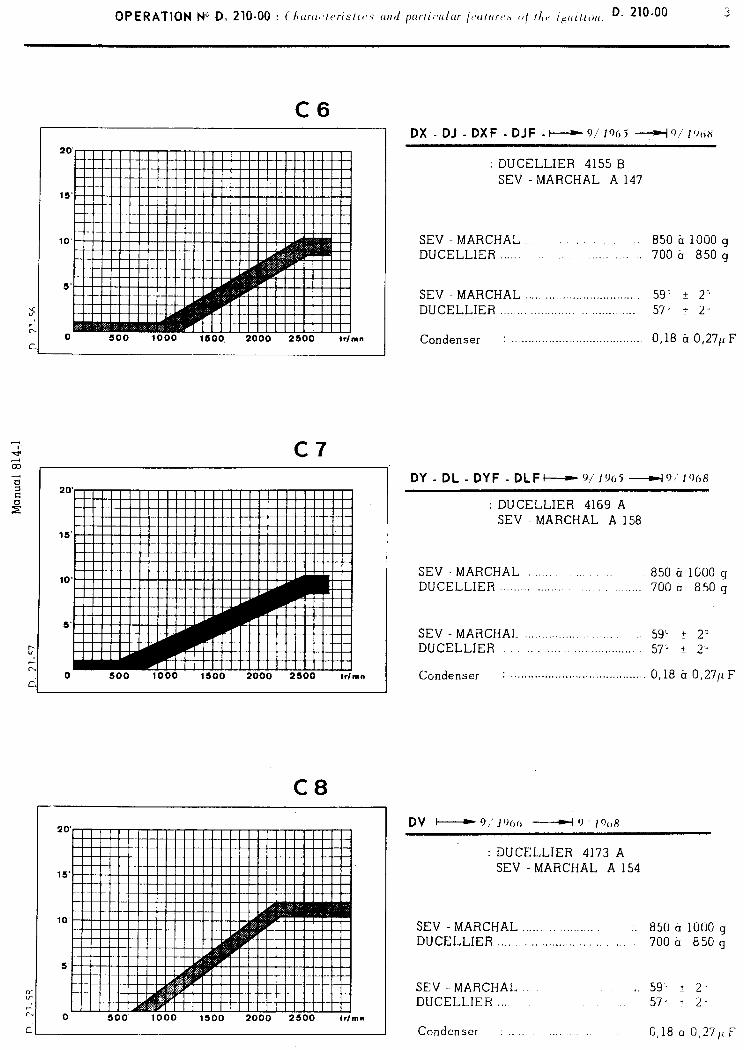
C6 OX - DJ - DXF - DJF -N9/’ 19~15 --L(o/ I’JOX
8”
0 500 1000 1500 2000 2500 irlmn
C8
0 500 1000 1500 2000 2500
: DUCELLIER 4155 B SEV-MARCHAL Al47
SEV - MARCHAL... . 850 b 1000 g DUCELLIER _..._.. .._:, ;. 700 h 850 g
SEV MARCHAL . . . 59; f 2" DUCELLIER ..I..... ,.. . . . 57- r 2
Condenser : . . . . . . . , 0,18 ?I 0,27/'F
DY - DL - DYF - DLFc-r- 9]19(,5 --w+o/~o(,~
: DUCELLIER 4169 A SEV MARCHAL A 158
SEV -MARCHAL . 850 ti 1000 g DUCELLIER . . . . ..:. 700 a 850 g
SEV - MARCHAI. .............. DUCELLIER ............... .: ............
59'. + 2O 57- t 2'3
Condenser : ....................................... 0,18 h 0,271~ F
DV - 9,’ I’)(,(, - 0 ’ JCoR
:DUCELLIER 4173 A SEV -MARCHAL Al54
SEV - MARCHAL ........ .......... 850 a 1000 g DUCELLIER ............................. 700~ 850g
SEV-.MARCHAL.. . . 59, 2 2, DUCELLIER... 57' t 2-
Condenser : 0,18 a 0,27,tF
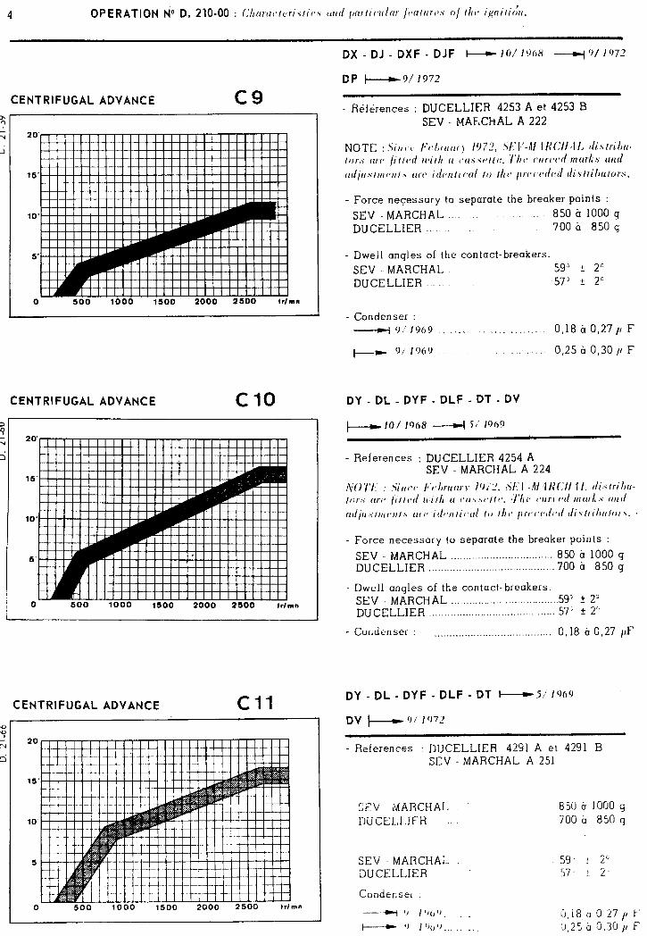
CENTRIFUGAL ADVANCE
0 500 1000 1500 2000 2500 trlmn
CENTRIFUGAL ADVANCE Cl0
CENTRIFUGAL ADVANCE Cl1
0 500 1000 1500 2000 2500 trlmn
DX - DJ - DXF - DJF + 10/ 1968 ----q”/ 197’
DP +9/1372
- References : DUCELLIER 4253 A et 4253 B SEV MAF,ChAL A 222
- Force necessary to separate the breaker points : SEV - MARCHAL .,,. 850 ir 1000 g DUCELLIER 700 ti 850 g
- Dwell angles of the contact-breakers. SEV - MARCHAL 59” t 2” DUCELLIER 573 5 2c
- Condenser : __c1 9,'1969 1, 1~1. ,, IL, _"l,rI 0,18 tr 0,27 p F
+- 9/1969, /_ ,i. 0,25 b 0,30 11 F
DY - DL - DYF - DLF - DT - DV
- Force necessary to separate the breaker points :
SEV - MARCHAL . . . ..__..._....................... 850 b 1000 g DUCELLIER ._.___.................................... 700 h 850 g
- Dwell angles of the contact-breakers SEV - MARCHAL __.,,..._............... . . . . . . . . . . . 59’ ? 2” DIJCELLIER _,__..__........_....,............. . . . . . 57’ t 2”
- Condenser : . . . . . . . . . . ..__...__.................... 0, 18 h 0,27 /lF
DY - DL - DYF - DLF - DT W si 1969
- References : DUCELLIER 4291 A et 4291 B SEV - MARCHAL A 251
SEV MARCHAL 850 h 1000 g DIJ CELLIER 700 a 850 g
SEV MARCHAL DUCELLIER
Condenser
59,. f 2” 57. f 2.
----+-I ‘1 I ‘)I, ‘1 . G,i8 h 0,27 11 F - ‘J I ‘)I, ‘J . . . ICI,25 b 0,30 ,l F
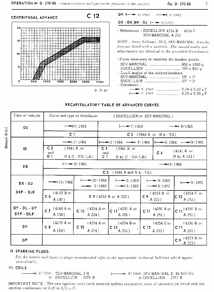
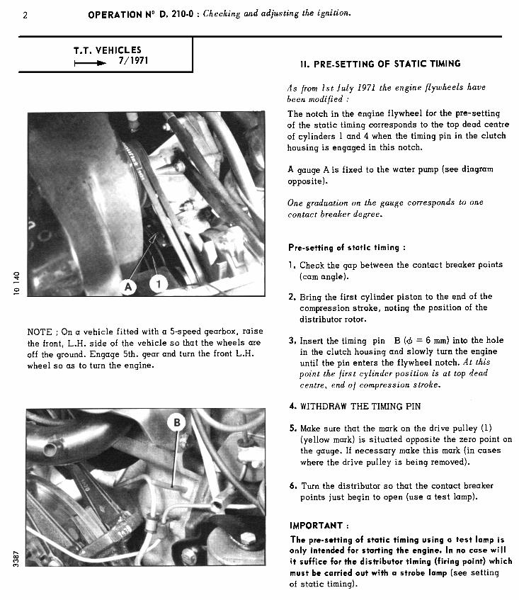
8 OPERATION No D. ,210 - 0 : Checking and adjusting the ignition
VII. TEST BENCH CHECK OF A DISTRIBUTOR.
The curves and characteristics of the dif/ erent types o/distributor are shown in operation D. 210-00.
1. Check the condition of the contact breaker points and adjust the contact gap.
2. Position the distributor on the test bench and connect the bench coil negative to the primary terminal of the dis- tributor.
3, Check the insulation of the secondary circuit,
Adjust the spark gaps to 7 mm. Connect the secondary terminal of the coil to the central contact of the distributor and the spark plug leads to the contact breakers.
Allow the distributor to turn at 1000 r.p.m. for fifteenminutes. There must be no misfiring.
4. Check the spark grouping :
The angular difference must not exceed 1030’ max. at all speeds (max. distributor speed : 3000 r.p.m. ). At each opening point the max. variation of the spark positions must not be more than lo 30’.
5. Check the dwell angles of the contact breakers,
DUCELLIER distributor 57 + 20
SEV- MARCHAL distributor 59 f 2O
6. Check the adfustment of the automatic ignition advance curve.
The actual curve must be between the minimum and maximum curves on the graph.
NOTE : a) It is possible to modify the tension of the flyweight springs by bending the spring anchor clips.
b) I f there are sparks at any other than the four normal positions the cam follower contact is bouncing. Check the force necessary to separate the points.( I.
7. Check the primary circuit insulation.
With the condenser removed bring the temperature of the distributor to 60” (‘140’ F). When the contact points are open apply 110 volts alternating current between the insulated positive terminal and earth, inserting a lamp in series. Maintain this voltage for 1 min. The lamp must not light up. [f it does the insulation is defective.
8, Check the condenser.
a) Check the insulation : Apply 110 volts alternating current between the condenser and its casing for 1 min. Insert a mains lamp in series in the circuit, I f the lamp lights the insulation is defective.
b) Check the capacities : - Use a capacitance -meter.
r- VIII. CLEANING AND ADJUSTING THE SPARK PLUGS,.
NOTE : This operation is necessary after prolonged town driving at low speed. Such use of the vehicle induces considerable fouling of the plugs.
9, Eliminate all lead and oil deposits on the insulator and electrodes by using a hardwood spatula. Do not use any metallic object.
10. Clean the plugs in petrol and blow out with compressed air.
11. Clean the plugs with a sand- blasting machine, supplied with compressed air at 6 bars max. (65 p,s.i. )
Blow out with an air jet at a maximum pressure of 4 bars ( 56 p.s.i. ) to remove the sand without forcing any between the insulator and the body of the plug.
IMPORTANT NOTE : Incomplete cleaning of fhe plugs after sand- blasting can clause rapid engine u ear. It is therefore essential to eliminate all traces o/’ sand after this operation.
12. Remove all sand thatmay be left on the base of the insulator by scraping with a very hard wood spatula,
13. Maintaining the sand-blasting machine.
a) Use only the sand supplied by the manufacturer of the machine.
b) Store the sand in a very dry place.
c) Renew the sand in the machine after cleaning about 100 plugs.
14. Adjust the electrode gaps too,60 mm - 0.70 mm (0.024 to 0.028 in)
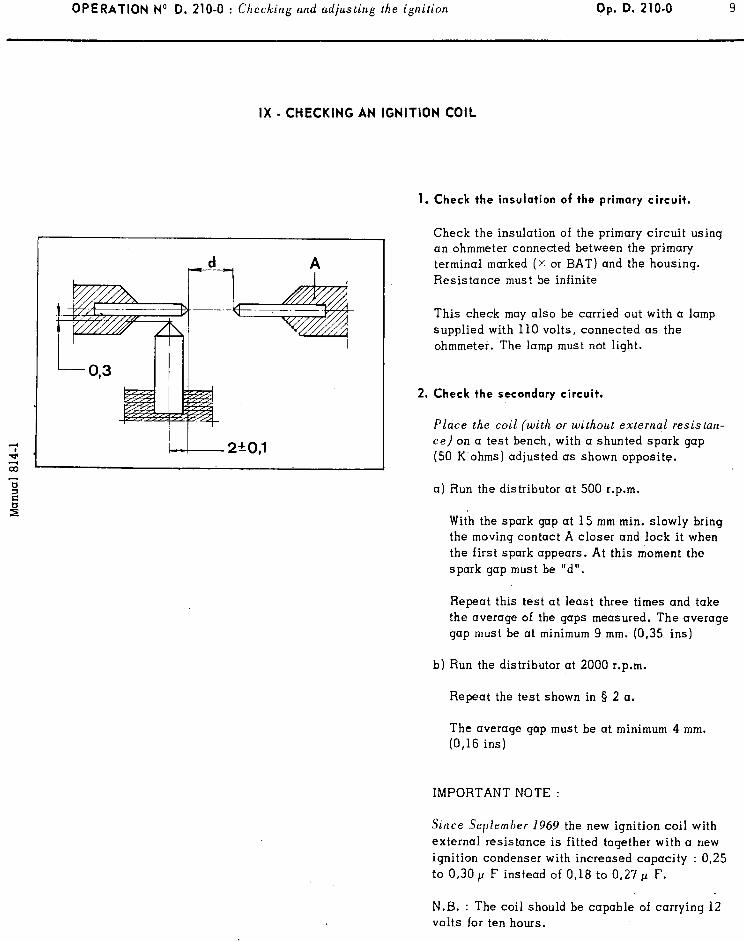
OPERATION NO D. 210-O : Ch li’ ec Lng and adjusting the ignition Op. D. 210-O 9
IX - CHECKING AN IGNITION COIL
1. Check the insulation of the primary circuit.
Check the insulation of the primary circuit using an ohmmeter connected between the primary terminal marked (x or BAT) and the housing. Resistance must be infinite
This check may also be carried out with a lamp supplied with 110 volts, connected as the ohmmeter. The lamp must not light.
2, Check the secondary circuit.
Place the coil (with or without external resistun- ce) on a test bench, with a shunted spark gap (50 K.ohms) adjusted as shown opposite.
a) Run the distributor at 500 r.p.m.
With the spark gap at 15 mm min. slowly bring the moving contact A closer and lock it when the first spark appears. At this moment the spark gap must be “d”.
Repeat this test at least three times and take the average of the gaps measured. The average gap must be at minimum 9 mm. (0,35 ins)
b) Run the distributor at 2000 r.p.m.
Repeat the test shown in § 2 a.
The average gap must be at minimum 4 mm. (0,16 ins)
IMPORTANT NOTE :
Since Sepfemher 1969 the new ignition coil with
external resistance is fitted together with a new ignition condenser with increased capacity : 0,25 to 0,30 p F instead of 0,18 to 0,27 p F.
N.B. : The coil should be capable of carrying 12 volts for ten hours.
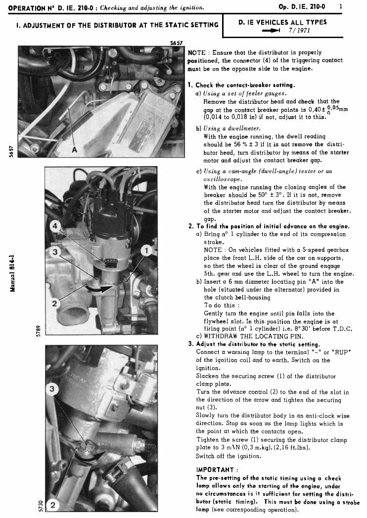
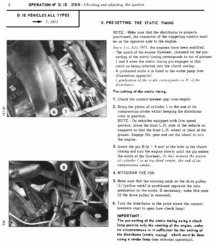
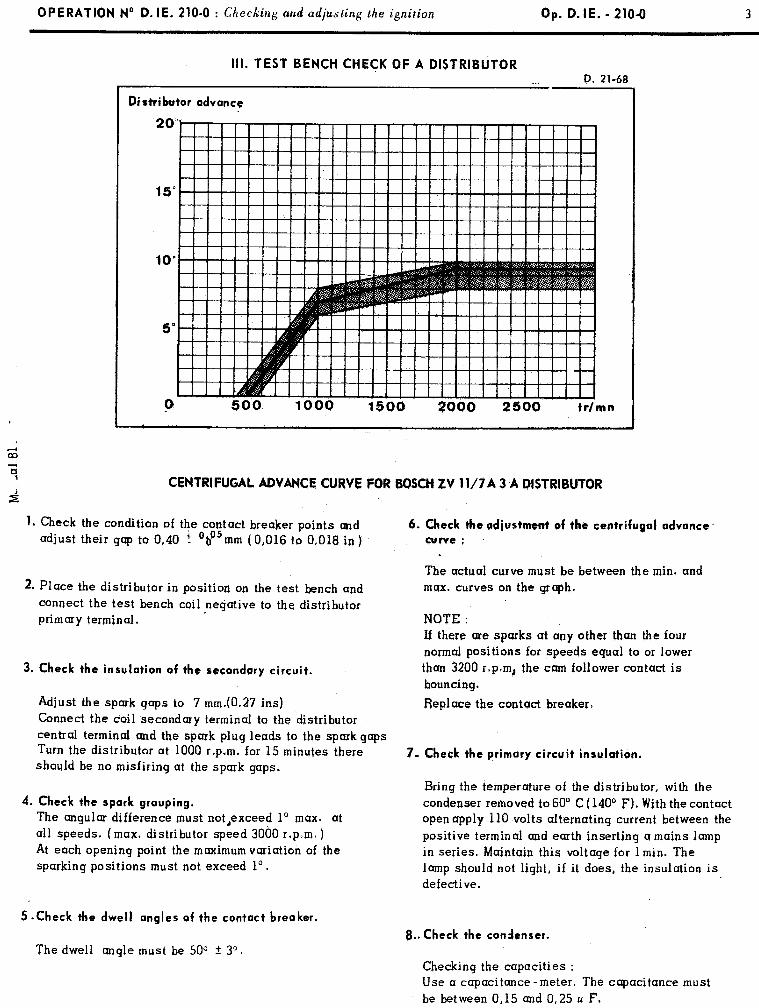
OPERATION No D. IE. 218-O : Checking and adjusting the ignition Op. D. IE. - 210-8 3
Ill. TEST BENCH CHECK OF A DISTRIBUTOR D. 21-6R
Distributor advance
20
P 500. 1000 1500 2000 2500 Wmn
CENTRIFUGAL ADVANCE CURVE FOR BOSCH ZV 11/7A 3 A DISTRIBUTOR
I. Check the condition of the contact breaker points and adjust their gap to 0,40 f ‘bo5mm (0,016 to 0,018 in)
2. Place the distributor in position on the test bench and connect the test bench coil negative to the distributor primary terminal.
3. Check the insulation of the secondary circuit.
Adjust the spark gaps to 7 mm(O.27 ins) Connect the coil secondary terminal to the distributor central terminal curd the spark plug leads to the spark gaps Turn the distributor at 1000 r.p.m. for 15 minutes there should be no misfiring at the spsrk gaps.
4. Check the spark grouping.
The angular difference must not,exceed lo max. at all speeds. (max. distributor speed 3060 r,p.m. ) At each opening point the maximumvariation of the sparking positions must not exceed 1”.
5 .Check the dwell angles of the contact breoker.
The dwell angle must be 50” f 3”.
6. Check the adiustment of the centrifugal advance’
curve : .
The actual curve must be between the min. and max. curves on the graph.
NOTE : If there core spurks at any other than the four normal positions for speeds equal to or lower than 3200 r.p.m, the cam follower contact is bouncing.
Replace the contact breaker.
7- Check the primary circuit insulation.
Bring the temperature of the distributor, with the condenser removed to 60” C ( 140° F). With the contact open apply 110 volts alternating current between the positive terminal and earth inserting cr mains lamp in series. Maintain this voltage for 1 min. The lamp should not light, if it does, the insulation is defective.
8.. Check the condenser.
Checking the capacities : Use a capacitance-meter. The capacitance must be between 0,15 and 0,25 u F.
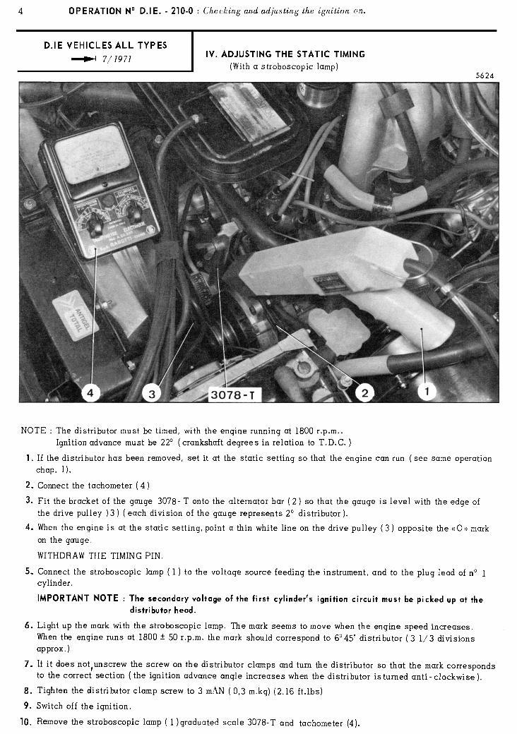
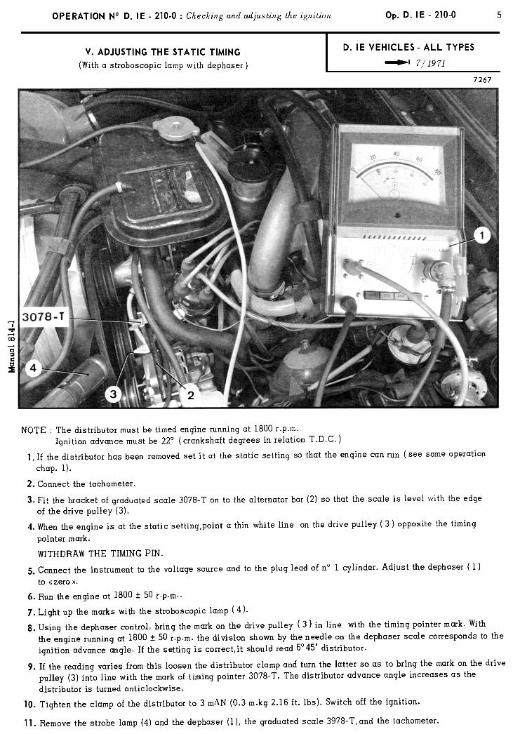
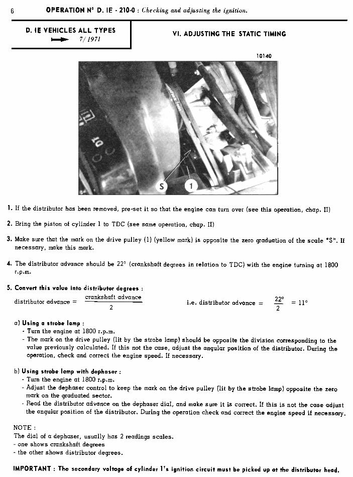
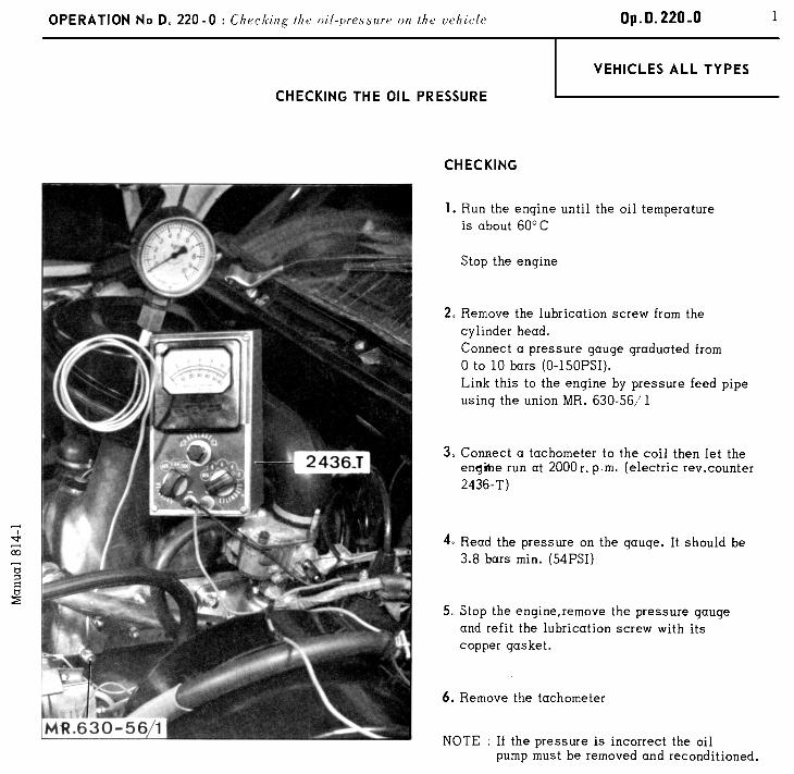
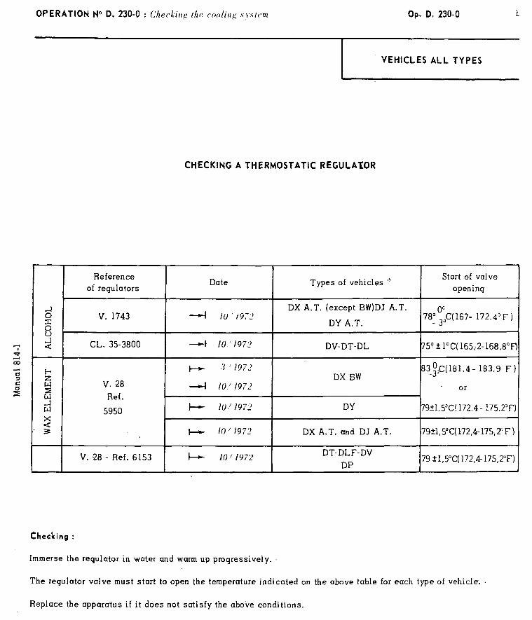
OPERATION N” D. 230-O : Checkirrg /ht~ coo/irlg .s~~s/t’m Op. D. 230-O
VEHICLES ALL TYPES
CHECKING A THERMOSTATIC REGULATOR
Reference Date Types of vehicles ‘.
Start of valve
of regulators opening
E: 4 DX A.T. (except BW)DJ A.T.
i?
v. 1743 lU’i9,L’ DY A.T.
78; 0300C( 167- 172.45 F )
t: ‘;’ 4 CL. 35-3800 4 10,‘197’, DV-DT-DL 75q f l”C( 165,2- 168,8”F) 2 03 ’ G + 3 1972 183.9 F) 2
iii DX BW
83$$(181.4-
3 2 v. 28 4 iv,/ 197’ or
1 Ref. 5950
b 10: 1972 DY 79+1.SC( 172.4- 175.2’F)
2 . 3 + /o/ 197’ DX A.T. and DJ A.T. 79+1,5”C( 172,4-175,2”F 1
V. 28 - Ref. 6153 I-+ 10/1972 DT-DLF-DV
DP 79 kl,S”C( 172,4-175,2”F)
Checking :
Immerse the regulator in water and warm up progressively.
The regulator valve must start to open the temperature indicated on the above table for each type of vehicle. .
Replace the apparatus if it does not satisfy the above conditions.
*A-T. : All types.
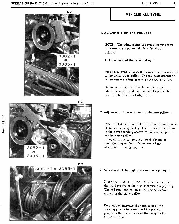

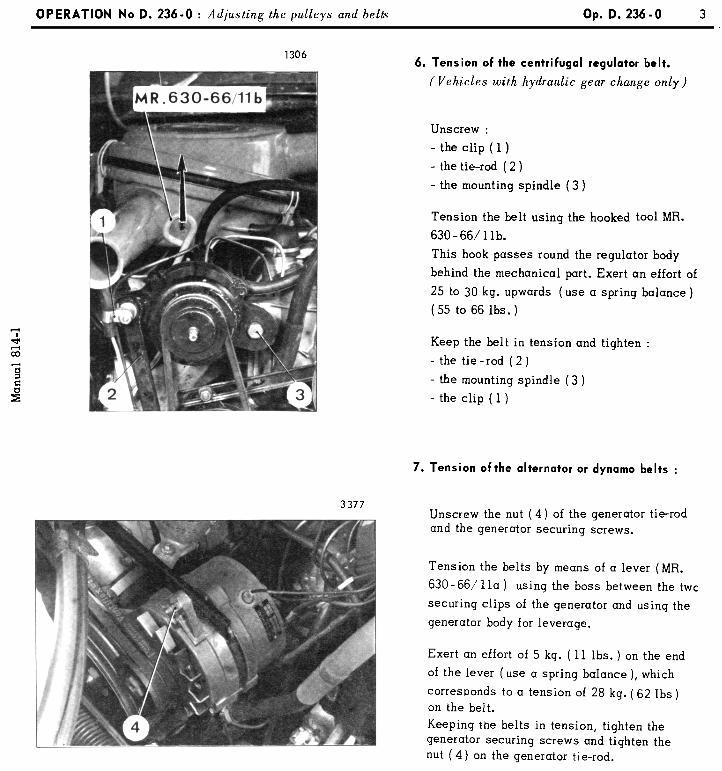
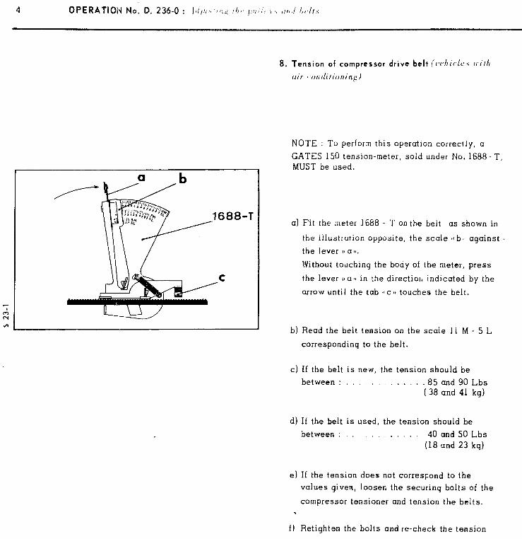
4 OPERATION No. D. 236-O : lr///,\‘,‘:, f/i<, I,‘:‘/, i, ,,,/J I,~,/~.<
8. Tension of compressor drive belt il~t~hir~lc~ with
clir -otrditioning)
NOTE : To perform this operation correctly, a
GATES 150 tension-meter, sold under No. 1688 - T, MUST be used.
a) Fit the meter 1668 - ‘I’ on the beit as shown in
the iilustrution opposite, the scale I( bl against
the lever v al!.
Without touching the body of the meter, press
the lever 11 a $1 in the direction indicated by the
arrow until the tab ~CCI~ touches the belt.
b) Read the belt tension on the scale 11 M - 5 L
corresponding to the belt.
c) I f the belt is new, the tension should be
between : , . . j . . 85 and 90 Lbs ( 38 and 41 kg)
d) If the belt is used, the tension should be
between : . . , I . 40 and 50 Lbs (18 and 23 kg)
e) If the tension does not corresqond to the
values given, loosen the securing bolts of the
compressor tensioner and tension the belts.
f) Retighten the bolts and re-check the tension
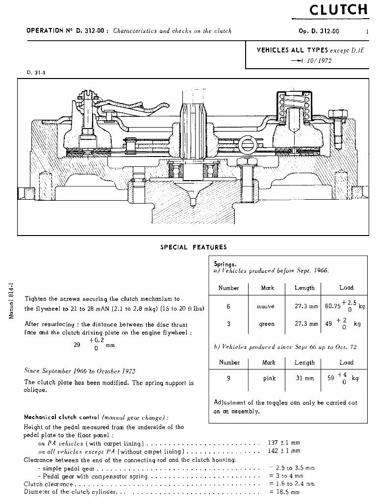
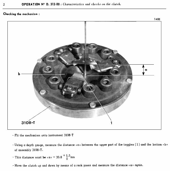
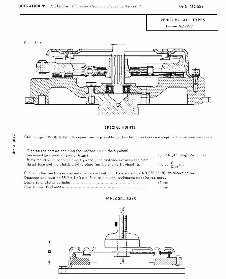
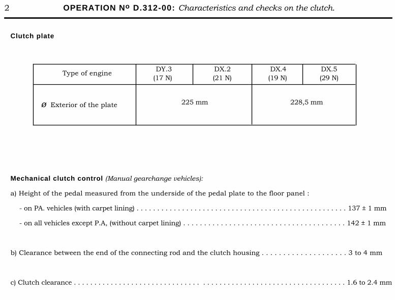
2 OPERATION No D.312-00: Characteristics and checks on the clutch.
Clutch plate
Type of engine
ø Exterior of the plate
DY.3 DX.2 (17 N) (21 N)
225 mm
DX.4 DX.5 (19 N) (29 N)
228,5 mm
Mechanical clutch control (Manual gearchange vehicles):
a) Height of the pedal measured from the underside of the pedal plate to the floor panel :
- on PA. vehicles (with carpet lining) . . . . . . . . . . . . . . . . . . . . . . . . . . . . . . . . . . . . . . . . . . . . . . . . . . . 137 ± 1 mm
- on all vehicles except P.A, (without carpet lining) . . . . . . . . . . . . . . . . . . . . . . . . . . . . . . . . . . . . . . . 142 ± 1 mm
b) Clearance between the end of the connecting rod and the clutch housing . . . . . . . . . . . . . . . . . . . . 3 to 4 mm
c) Clutch clearance . . . . . . . . . . . . . . . . . . . . . . . . . . . . . . . . . . . . . . . . . . . . . . . . . . . . . . . . . . . . . . . . . . 1.6 to 2.4 mm

CLUTCH
.r: sr 4 SPECIAL POINTS co
-2 5 z:
Clutch type 230 - DIB 440. No operation is possible on the clutch mechanism except for the mechanism check.
- Tighten the bolts securip, the mechanism on the flywheel (grower washer) TO<..- 40 m \N (4 mkg) (29 ft Ibs) - After resurfacing of the engine flywheel, the distance between the disc
thrust face and the clutch driving plate (on the engine flywheel) is . . . . . . . . . . . . . . . . z 0.35 0 - 0.15mm
Checking the mechanism can only be carried out on a fixture (fixture MR 630-55/g), as shown below. Distance ccat) must be 59.8 f 1.40 mm. If it is not, the mechanism must be replaced. Diameter of clutch cylinder . . . . . . . . . . . . . . . . . . . . . . . ..,.......... . . . . . . . . . . . . . . . . . . . . . . . . . . . . . . ..: 22.5 mm 4 7 ’ 197.2
24 mm + 7 ’ l97L’ MR. 630s 55/g
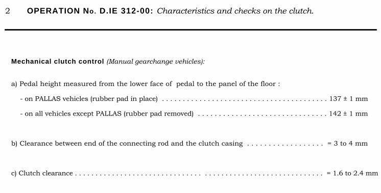
2 OPERATION No. D.IE 312-00: Characteristics and checks on the clutch.
Mechanical clutch control (Manual gearchange vehicles):
a) Pedal height measured from the lower face of pedal to the panel of the floor :
- on PALLAS vehicles (rubber pad in place) . . . . . . . . . . . . . . . . . . . . . . . . . . . . . . . . . . . . . . . . 137 ± 1 mm
- on all vehicles except PALLAS (rubber pad removed) . . . . . . . . . . . . . . . . . . . . . . . . . . . . . . . 142 ± 1 mm
b) Clearance between end of the connecting rod and the clutch casing . . . . . . . . . . . . . . . . . . = 3 to 4 mm
c) Clutch clearance . . . . . . . . . . . . . . . . . . . . . . . . . . . . . . . . . . . . . . . . . . . . . . . . . . . . . . . . . . . . = 1.6 to 2.4 mm
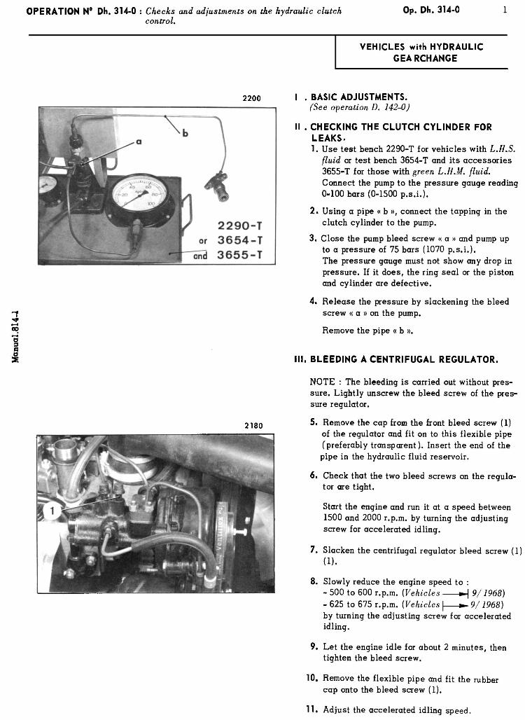
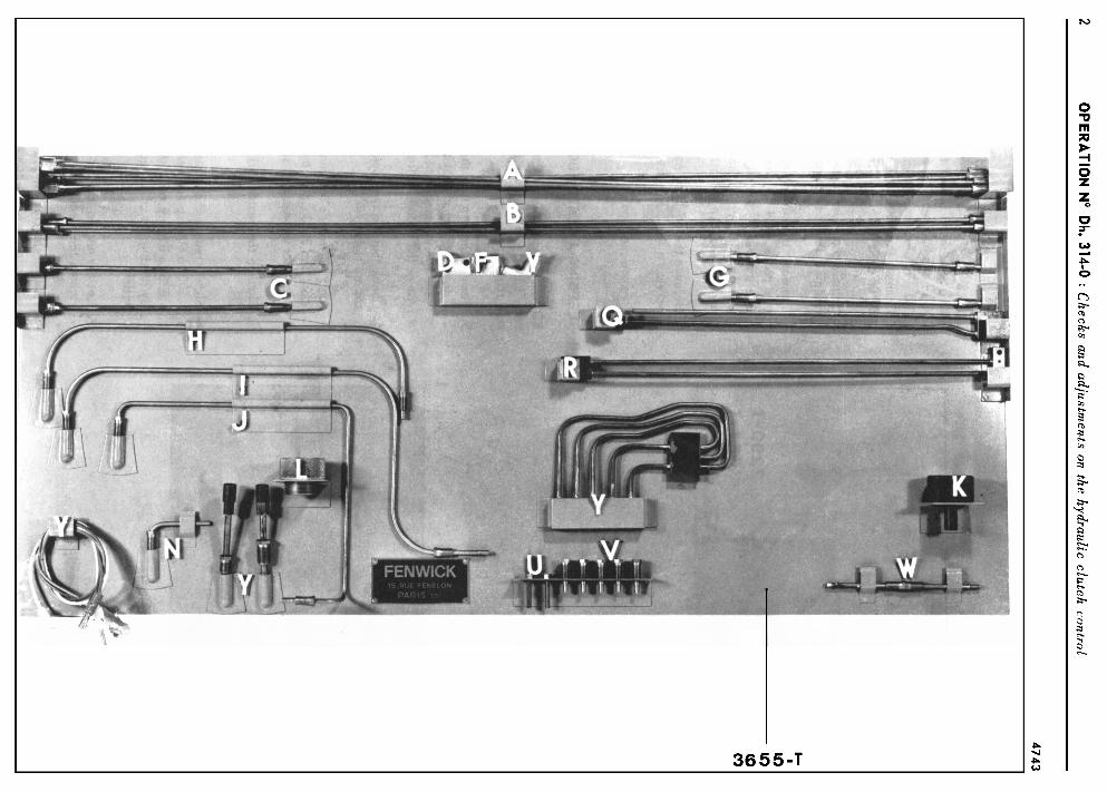
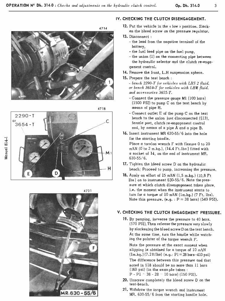
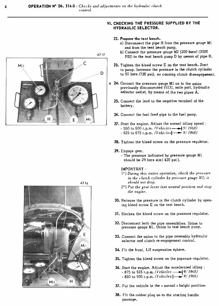
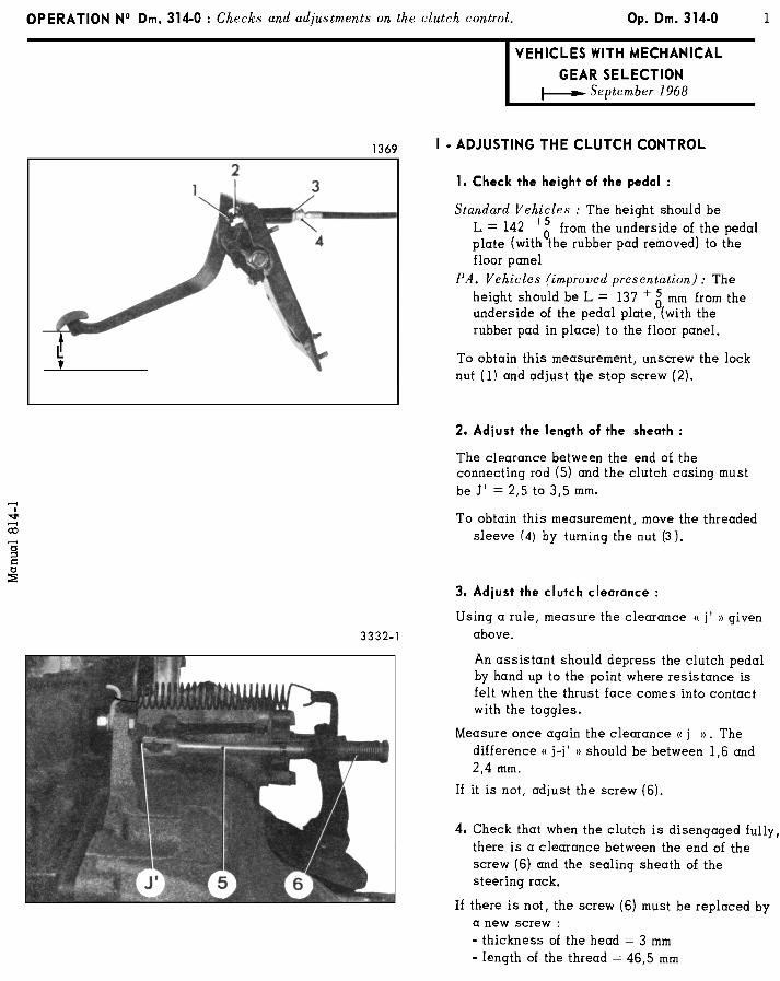
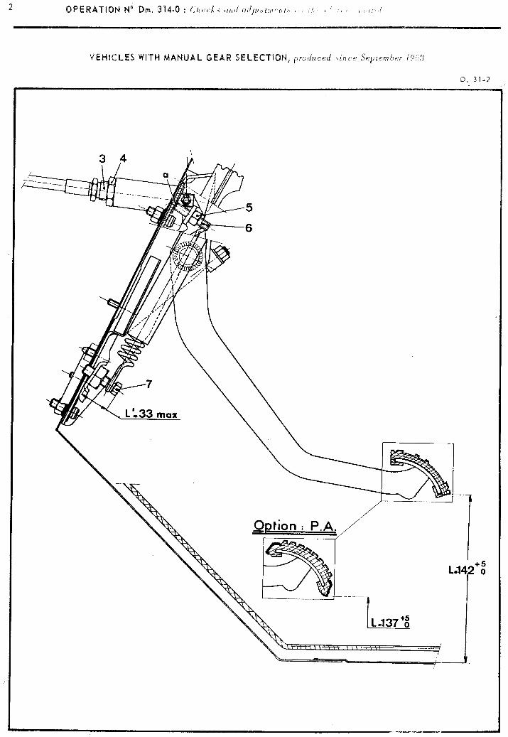
--
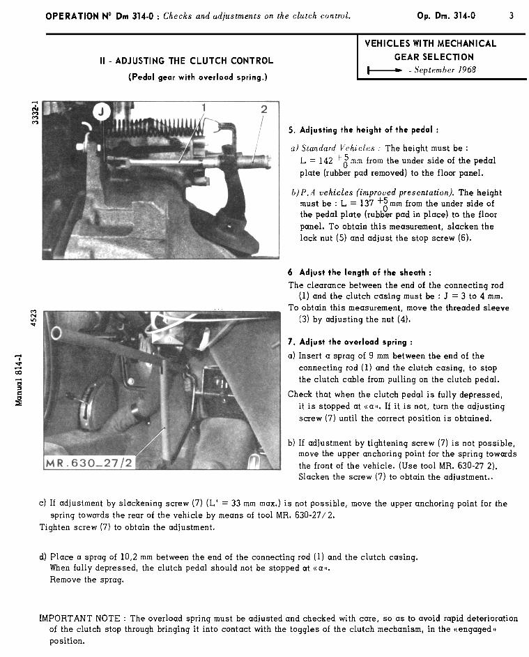
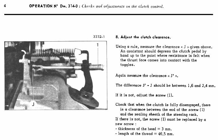
TORQUE CONVERTER
OPERATION NO. Dbw 320-00 : Ch aracteris tics and particular features Op. Dbw 320-00 1
of the torque converter
I DBW. VEHICLES All types
1. DESCRIPTION
- The “DS 21” vehicles (carburettor or electronic fuel Injection) may be optionally fitted with a BORG-WARNER
fully automatic gearbox “type 35”.
- Principal components of the transmission :
- A torque converter composed of three elements (impellor, turbine, reactor) permitting a variable
multiplication ratio of the torque, from 2.3 to 1.
- An oil pump (activated by the converter rmpellor) supplying oil under pressure necessary to the
operation of the converter and the hydraulic gear change control unit and also for the lubrication of
the epicyclic gear train.
- A hydraulically controlled automatic gear box, including an epicyclic gear train making it possible
to obtain three forward gears and one reverse gear.
II. ADVANTAGES OF THE CONVERTER
- The converter multiplies the engine torque when starting and on accelerating, allowing :
- the use of only a 3-speed gearbox,
- flexible driving behaviour, even at low speeds,
- rapid acceleration at low engine speed,
- increased “pulling power”, a desirable quality when pulling caravans or for driving with full load.
- The converter, couplad with an epicyclic gear train gearbox makes the following possible :
- the elimination of the classical cut out clutch,
- the damping of noises and vibrations, the engine being mecharfically isolated from the gearbox.
- The converter ensures under all circumstances smooth transmission of the power generated by the engine
without any jolting.


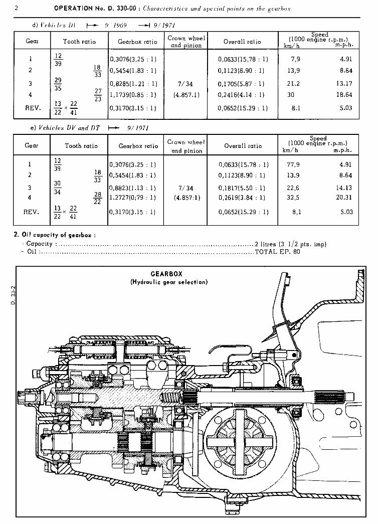
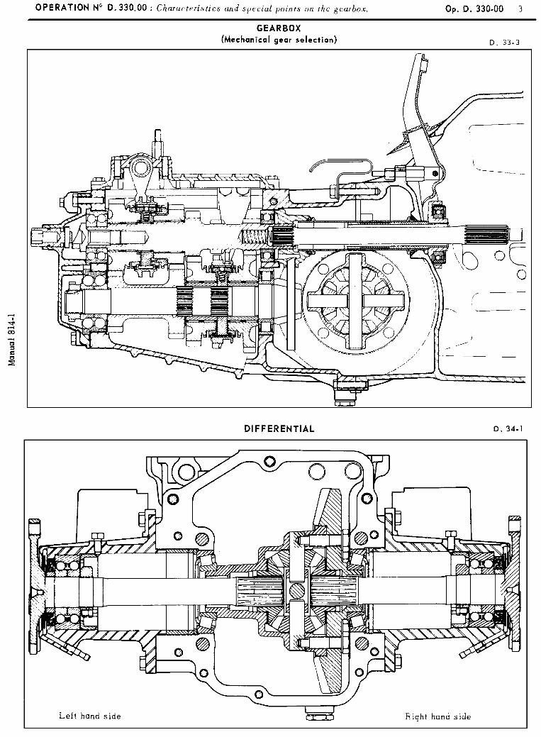
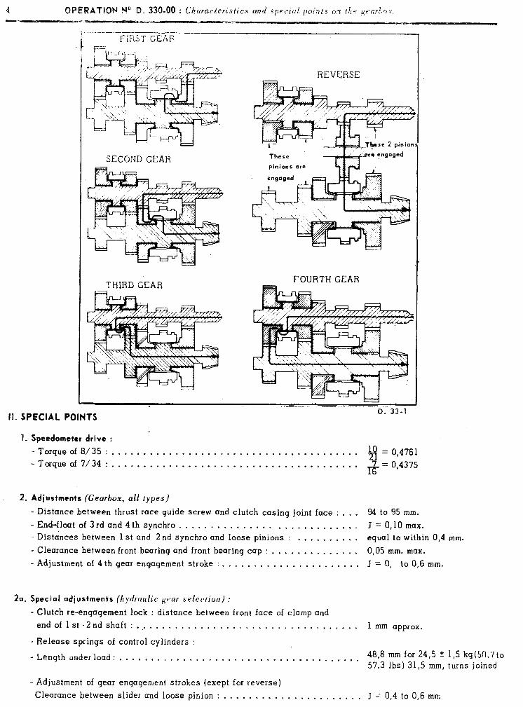
4 OPERATION No D. 330-00 : Ch uracteristics and special p0int.s on the ,ge:irtri~. -_j.- .L- .a=-.
SECOND GEAR
THIRD GEAR U
REVERSE
These
pinions ore
FOURTH GEAR
II. SPECIAL POINTS IJ. JJ-I
1. Speedometer drive :
- Torque of 8/35 : . . . . . . . . . . . . . . . . . . . . . . . . . . . . . . . . . . . . . . . 8 = 0,4761
-Torque of 7/34 : . . . . . . . . . . . . . . . . . . . . . . . . . . . . . . . . . , . . . . . l+
= 0,4375
2. Adjustmenis (Gearbox, all types)
- Distance between thrust race guide screw and clutch casing joint face : . . . 94 to 95 mm.
-Er&floatof3rdand4thsynchro . . . . . . . . . . . . . . . . . . . . . . . . . . . . J=O,lOmax. - Distances between 1 st and 2 nd synchro and loose pinions : . . . . . . , . . . equal to within 0,4 mm.
- Clearance between front bearing and front bearing cap : . . . . . . . . . . . . . . 0,05 mm. max.
- Adjustment of 4 th gear engagement stroke : . . . . . . . . . . . . . . . . , , . . . . J = 0, to 0,6 mm.
2a. Special adjustments (hydraulic geur selection) :
- Clutch re-engagement lock : distance between front face of clamp and endoflst-2ndshaft: .,.....................,...,....,... 1 mm approx.
- Release springs of control cylinders :
- Length under load : . . . , . . . . . . . . . . . . . . . . . . . . . . . . . . . . . . . . . . 48,8 mm for 24,5 f 1‘5 kg(511.710 57.3 Ibs) 31,5 mm, turns joined
- Adjustment of gear engagement strokes (exept for reverse)
Clearance between slider and loose pinion : . . . . . . . . . . . . . . . . . . . . . . J z 0,4 to 0,6 mm
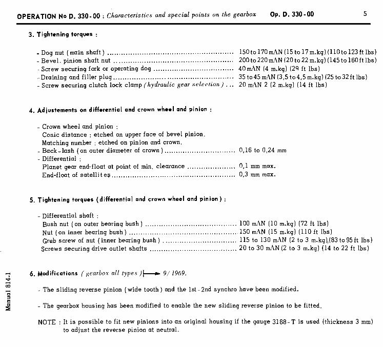
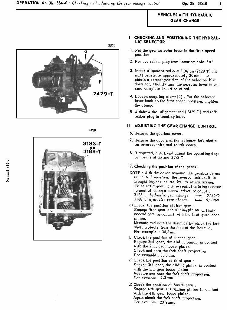
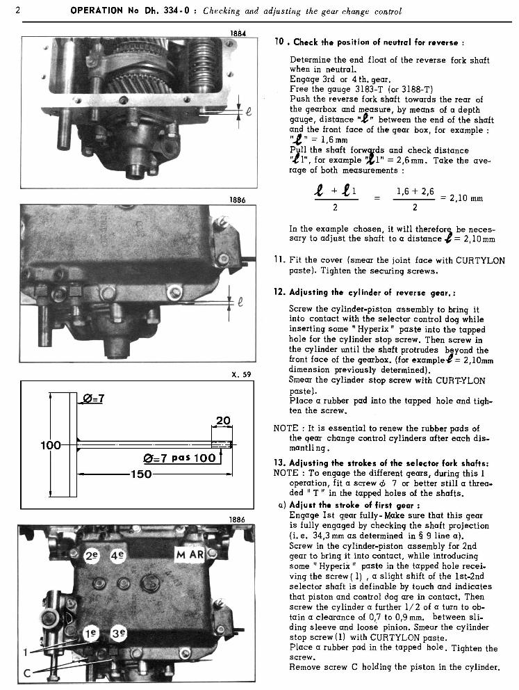

OPERATION No Dh. 334-O :Checking and adjusting the gear change control Op. Dh. 334 - 0 3
-b) Adjust the stroke uf-second gear :
Pull on the shaft to engage 2nd gear fully, l Make sure that gear is fully engaged by
checking the shaft projection (for example 55,3 mm as determined in 8 9 line b)
Remove screw or threaded T fitted on the end of the shaft.
Bring the cylinder-piston assembly for first gear in contact with the control dog and operate as described above.
c)Adiust the stroke of third gear.
Engage 3 rd gear fully. Make sure that the gear is fully engaged by checking the shaft position (1,3 mm measurement determined in’s 9 line c )
Bring the cylinder-piston assembly for fourth gear in contact with the control dog and operate as indicated above in line a (1.3 mm. measure- ment determinedin 0 9, line C). (
d)Adiust the stroke of fourth gear.
Engage 4th gear fu!ly. Ensure that the gear is fully engaged by checking the protusion of the shaft (23,9 mm as measured in 0 9 line d )
Bring the cylinder-piston assembly for 3 rd gear in contact with the control dog and operate as described above in line a.
14.Fit the front cover over the end of reverse gear shaft Curtylon and the cover over the end of 3rd/4th gear shaft. 1
Make’srfe that the ring seal is in position
15. Adjusting the clutch lack :
With first gear engaged, ensure that there is a clearance (at “J “)‘between the clamp (1) and the head of the screw (2) securing the cover of the shaft
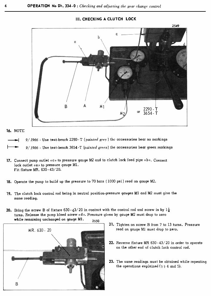
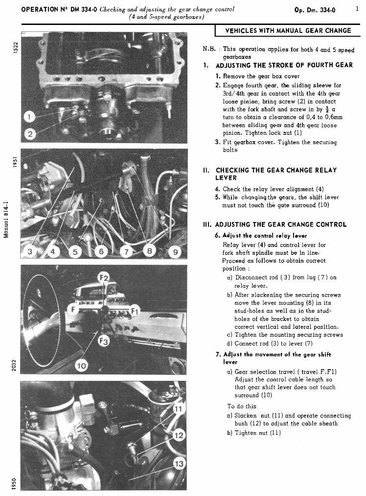
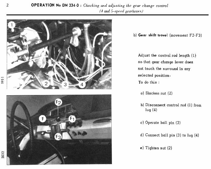
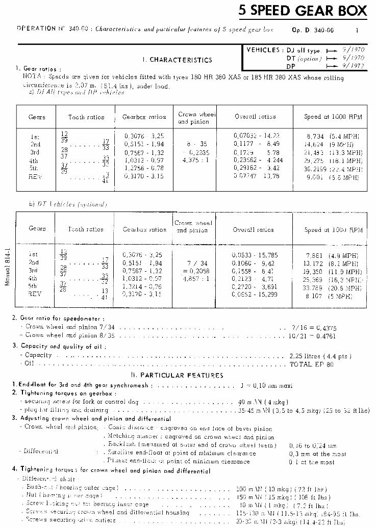
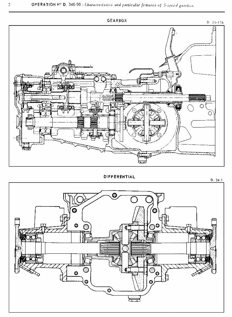
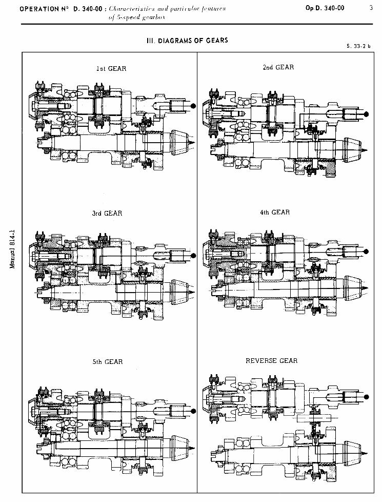
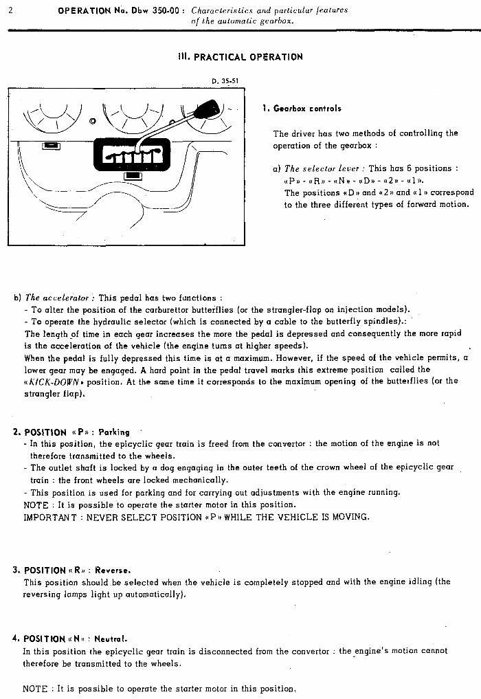
2 OPERATION No. Dbw 35040 : Characteristics and particular features 01 the automatic gearbox.
Ill. PRACTICAL OPERATION
D. 35-51
1. Gearbox controls
The driver has two methods of controlling the operation of the gearbox :
a) The selector lever : This has 6 positions : aP,, - c(R), - ctN, - aD,> - (t2a - ((1)). The positions u D )) and (( 2 )) and (( 1 u correspond to the three different types of forward motion.
b) The accelerator : This pedal has two functions : - TO alter the position of the carburettor butterflies (or the strangler-flap on injection models). - To operate the hydraulic selector (which is connected by a cable to the butterfly spindles).: The length pf time in each gear increases the more the pedal is depressed and consequently the more rapid is the acceleration of the vehicle (the engine turns at higher speeds). When the pedal is fully depressed this time is at a maximum. However, if the speed of the vehicle permits, a lower gear may be engaged. A hard point in the pedal travel marks this extreme position called the ((I\‘ICK-DOW/V* position. At the same time it corresponds to the maximum opening of the butterflies (or the strangler flap).
2. POSITION M Pbk : Porking ’ - In this position, the epicyclic gear train is freed from the convertor : the motion of the engine is not
therefore transmitted to the wheels. - The outlet shaft is locked by a dog engaging in the outer teeth of the crown wheel of the epicyclic gear
train : the front wheels are locked mechanically. - This position is used for parking and for carrying out adjustments with the engine running. NOTE : It is possible to operate the starter motor in this position.
IMPORTANT : NEVER SELECT POSITION UP,, WHILE THE VEHICLE IS MOVING.
3. POSITION (( R H : Reverse. This position should be selected when the vehicle is completely stopped and with the engine idling (the reversing lamps light up automatically),
4. POSITION ((NH : Neutral.
In this position the epicyclic gear train is disconnected from the convertor : the engine’s motion cannot therefore be transmitted to the wheels.
NOTE : It is possible to operate the starter motor in this position,
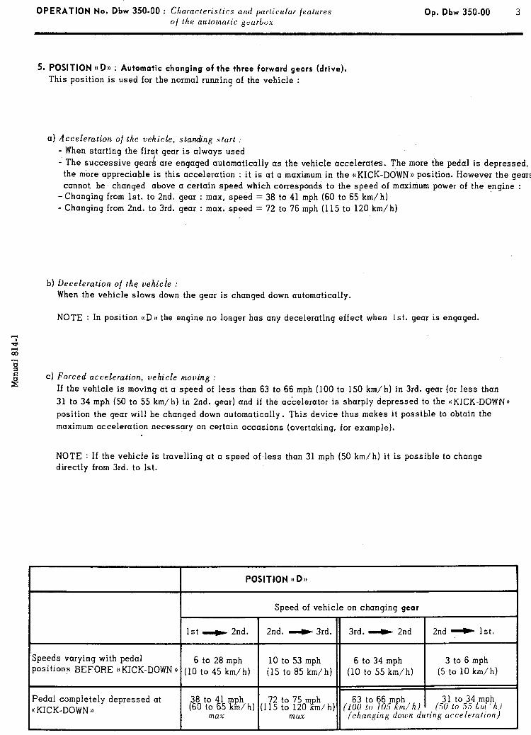
OPERATION No. Dbw 350-00 : Ch aracteristics and particular features Op. Dbw 350.00 3
of the automatic geurbon-
5, POSITION ((D)) : Automatic changing of the three forward gears (drive),
This position is used for the normal running of the vehicle :
a) Acceleration of the vehicle, standing start :
- When starting the firs.t gear is always used - The successive gearA are engaged automatically as the vehicle accelerates. The more the pedal is depressed, the more appreciable is this acceleration : it is at a maximum in the ((KICK-DOWN)) position. However the gears cannot be changed above a certain speed which corresponds to the speed of maximum power of the engine :
-Changing from 1st. to 2nd. gear : max, speed = 38 to 41 mph (60 to 65 km/h) - Changing from 2nd. to 3rd. gear : max. speed = 72 to 76 mph (115 to 120 km/h)
I
b) Deceleration of’ the vehicie : When the vehicle slows down the gear is changed down automatically.
NOTE : In position t(D), the engine no longer has any decelerating effect w.hen 1st. gear is engaged.
‘: q z -ii 2
e C) Forced acceleration, vehicle moving :
If the vehicle is moving at a speed of less than 63 to 66 mph (100 to 150 km/h) in 3rd. gear (or less than 31 to 34 mph (50 to 55 km/h) in 2nd. gear) and if the accelerator is sharply depressed to the ((KICK-DOWN)) position the gear will be changed down automatically. This device thus makes it possible to obtain the maximum acceleration necessary on certain occasions (overtaking, for example).
NOTE : If the vehicle is travelling at a speed of less than 31 mph (50 km/h) it is possible to change directly from 3rd. to 1st.
POSITION u DH
Speed of vehicle on changing gear
1st _ 2nd. 2nd. _ 3rd. 3rd. _ 2nd 2nd _ 1st.
Speeds varying with pedal 6 to 28 mph 10 to 53 mph 6 to 34 mph 3 to 6 mph Positions BEFORE ((KICK-DOWN )) (10 to 45 km/h) (15 to 85 km/h) (10 to 55 km/h) (5 to 10 km/h)
Pedal completely depressed at 38 to 41 (60
mph (1:; :z
!~Orn&h) 63 to 66 m h 31 to ((KICK-DOWN i) to 65 km/h) (ZOO to 105 Rm/h)
34 mph (50 lo 55 I, IN I h j
max max (changing down during acceleration)
4 OPERATION No,. Dbw 350-00 : Ch ura~~teristics illld purticular jeatures
o/ the automatic gearbox
6. POSITION a2)) : Automatic changing of the first two forward gears.
This position is used for town traffic or motoring in mountainous areas.
In this position the operation is identical to that of position t(D)), but only the first two gears are used. When the second gear is engaged, the speed of the vehicle is not limited : never exceed the maximum engine speed (6000 rpm)
NOTE : In this position the engine no longer has any braking effect when 1st. gear is engaged.
N.B : Changing down h) movirlg the lever jrom position a 1) e to position 4 2 11 ,’
In this case the engagement of the 2nd. gear is not restricted. It can occur at any speed.
CAUTION : In order to avoid efcessille speeds, which are harmful to the engine, nezper per,/orm this operation
at a speed higher than 81 mph (130 km/h).
7. POSITION (( 1)) : Locking of the first gear
This position is used for exceptional driving conditions : travelling up or down steep gradients (mountainous areas, garage ramps). In this position the vehicle normally starts in 1st. gear, but the latter remains locked, whatever the speed of the vehicle : never exceed the maximum speed of the engine (6000 rpm).
NOTE : This position of the lever is the only one in which the braking effect of the engine is used in 1st. gear.
N.B : Changing dozcm hy moljing the lezler from positions ti I) )> or 9 2 ‘, to position ‘c 1 *.
In this case the engagement of first gear is restricted to avoid excessive speeds which are harmful to the engine: it can never.take place at a speed.above the appropriate speed limit. The latter can have two values according to the position of the acceleratoc pedal :
- all positions, except at I( KICK-DOWN )). . . . . . , . . . : maximum speed = 31 - 34 mph (50 - 55 km/h) - pedal fully depressed at ((KICK-DOWN t) . , . . , . . . ,. : maximum speed = about 50 mph (80 km/h) If this operation is carried out at a higher speed, the 2nd gear will be engaged : first gear will not mesh until the vehicle has sufficiently slowed down and will then remained locked.
8. Starting the engine :
The starting motor can only be operated, using the ignition switch, when the selector lever is in positions (( N 1) or (( P )L
IMPORTANT : - It is impossible to start the engine by towing the vehicle.
- Never operate the starter motor relay (on the battery) I,~,/:JI,’ cil>urirfg that the s~~lector lerlrr is in povitioil
UN:> or aPu.
9, Towing the vehicle :
,4s a general rule, the jront of the vehicle should always he raised /or towing.
Exceptionally, however, and over very short distances, the vehicle can be towed slowly after putting the select- or lever in position ((N )) (provided that, however, the gearbox is working normally and that the oil-levels are correct).

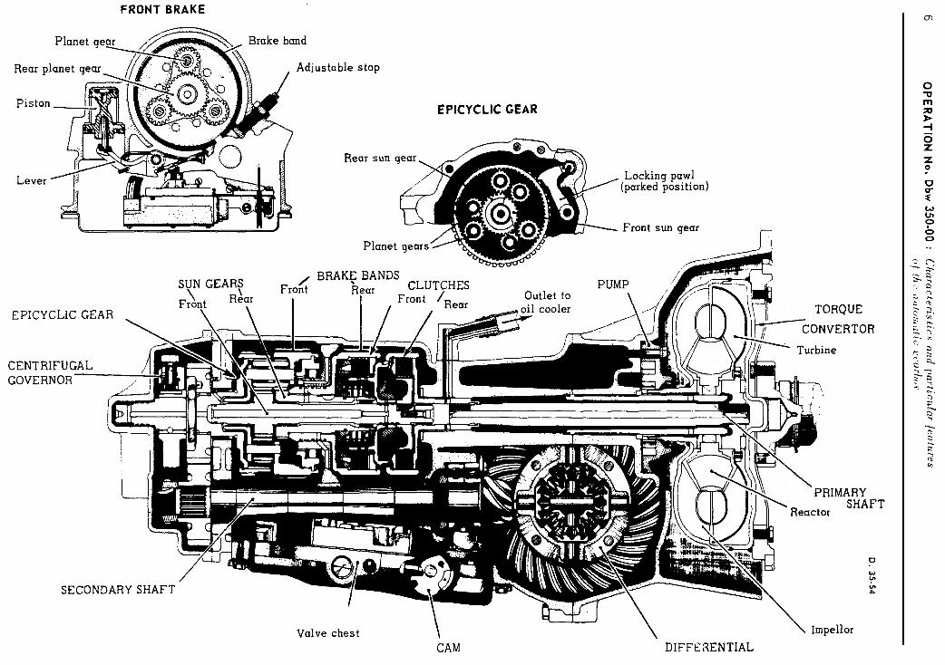
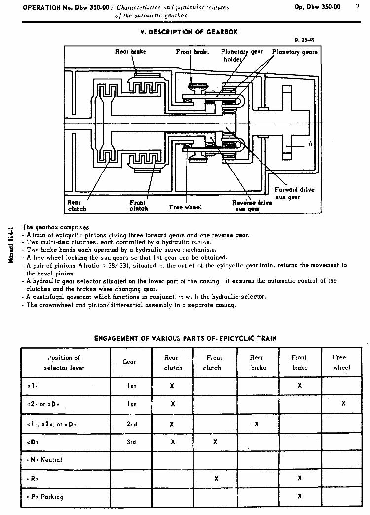

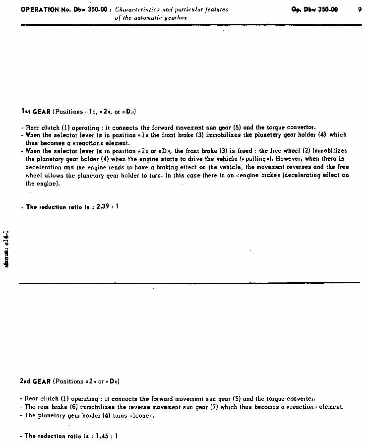
OPERATION No, Dbw 350-W : Ch aracteristics and particular jeatures Dp.Dbw350-00 9 of the automatic gearbox
1st GEAR (Positions N 1 )B, ((2)), or (( DB))
- Rear clutch (1) operating : it connects the forward movement sun gear (5) and the torque convertor. - When the selector lever is in position (( 1 n the front brake (3) immobilizes the planetary gear holder (4) which
thus becomes a *reaction I) element. . When the selector lever is in position a2 H or (tD)b, the front brake (3) is freed : the free wbsel (2) immobilizes
the planetary gear holder (4) when the enqine starts to drive the vehicle (((pulling))). However, when there is deceleration qnd the engine tends to have a braking effect on the vehicle, the movement reverses and tbe free wheel allows the planetary gear holder to turn. In this case there is an N engine brake 1) (decelerating effect on the engine).
- The reduction ratio is : 2.39 : 1
2nd GEAR (Positions u 2 1) or M Dn)
- Rear clutch (1) operating : it connects the forward movement sun qesr (5) and the torque converter. - The rear brake (6) immobilizes the reverse movement sun gear (7) which thus becomes a ((reaction)) element. - The planetary gear holder (4) turns o loose )L
- The reduction ratio is : 1.45 : 1

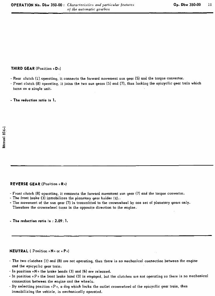
OPERATION No. Dbw 350-00 : Ch aracteris tics and particular features Op. Dbw 350-00 11 o/ the automatic gearbox
THIRD GEAR (Position (( Du)
- Rear clutch (1) operating, it connects the forward movement sun gear (5) and the torque convertor. - Front clutch (8) operating, it joins the two sun gears (5) and (7), thus locking the epicyclic gear train which
turns as a single unit.
- The reduction ratio is 1.
REVERSE GEAR (Position o R4
- Front clutch (8) operating, it connects the forward movement sun gear (7) and the torque convertor. - The front brake (3) immobilizes the planetary gear holder (4). , - The movement of the sun gear (7) is transmitted to the crownwheel by one set of planetary gears only.
Therefore the crownwheel turns in the opposite direction to the engine.
- The reduction ratio is : 2.09: 1.
NEUTRAL ( Position M NO or (( PJ))
- The two clutches (1) and (8) are not operating, thus there is no mechanical connection between the engine and the epicyclic gear train,
- In position ctN)r the brake bands (3) and (6) are released. - In position ((PH the front brake band (3) is engaged, but the clutches are not operating so there is no mechanical
connection between the engine and the wheels. - By selecting position ((PD, a dog which locks the outlet crownwheel of the epicyclic gear train, thus
immobilizing the vehicle, is mechanically operated.
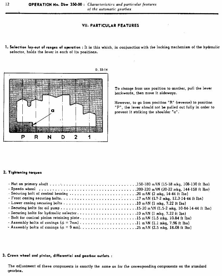
12 OPERATION No. Dbw 350-W : Ch aracteristics and particular features o/ the automatic gearbox
VII. PARTICULAR FEATURES
1. Selection lay-out of ranges of operation : It is this which, in conjunction with the locking mechanism of the hydraulic selector, holds the lever in each of its positions.
D. 33-14
PRND21
To change from one position to another, pull the lever backwards, then move it sideways.
However, to go from position “R” (reverse) to position “P”, the lever should not be pulled out fully in order to prevent it striking the shoulder “a”.
2. Tightening torques
- Nut on primary shaft ................................ .150-180 mAN (15-18 mkg, 108-130 ft Ibs) - Speed0 wheel ................................... .200-220 m-AN (20-22 mkg, 144-158 ft Ibs) - Securing bolt of central bearing ........................ .20 mhN (2 mkg, 14-44 ft Tbs) - Front casing securing bolts. .......................... .17 m.AN (l.7-2 mkg, 12.3-14-44 ft Ibs) - Lower casing securing bolts .......................... .lO mAN (1 mkg, 7.22 ft Ibs) - Securing bolts for oil pump ........................... .15-20 m.ZN (1.5-2 mkg, 10-84-14-44 ft Ibs) - Securing bolts for hydraulic selector. .................... .lO mAN (1 mkg, 7.22 ft Ibs) - Bolt for conical pinion retaining plate. ................... .15 m.\N (1.5 mkg, 18.84 ft Ibs) - Assembly bolts of casings (c$ = 7mm) .................... .ll m.dN (1.1 mkg, 7.96 ft Ibs) - Assembly bolts of casings (4 = 9 mm). ................... .25 mAN (2.5 mkg, 18.08 ft Ibs)
3, Crown wheel and pinion, differcntiol and gearbox outlets :
The adjustment of these components is exactly the same as for the corresponding components on the standard gearbox.
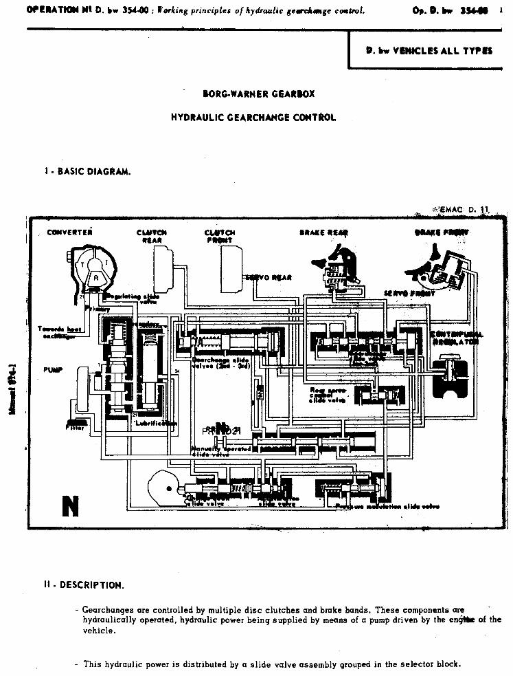
OfPRAT)oI w1 D. bw 35440 : Working principles of hydraulic gccekage mud. Dp.o.bw tsbm 1
I
0. bw VEWCLES ALL TYPIM
BORG-WARNER GEARBOX
HYDRAULIC GEARCHMGE CCMTkCJL
I - BASIC DIAGRAM.
cutvoRlti CuItcll MAU RRARL Rlql ruvrrr _’ :
II - DESCRIPTION.
- Gearchanges are controlled by multiple disc clutches and brake bands. These components are ’ hydraulically operated, hydraulic power being supplied by means of a pump driven by the encjW of the vehicle.
- This hydraulic power is distributed by a slide valve assembly grouped in the selector block.

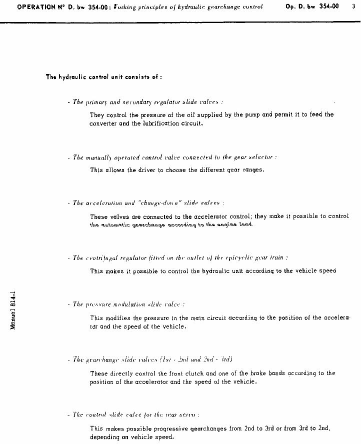
OPERATION N” D. bw 354-00: R’ or ing principles of hydraulic gearchange control k Op. D. bw 354-00 3
The hydraulic control unit consists of :
- The primary and secondary regulator slide l-all-es :
They control the pressure of the oil supplied by the pump and permit it to feed the converter and the lubrification circuit.
- The manually operated rvntrol l*alve connected to the gear selector :
This allows the driver to choose the different gear ranges.
- The acceleration arid “rhauge-dr,lc n ” slide ~~ull~es :
These valves are connected to the accelerator control; they make it possible to control the automatic gearchange according to the engine load.
- The cerltri/r,gal regulator /i/ted on I/IV uullel o/ the tJpic),clic. #car [rain :
This makes it possible to control the hydraulic unit according to the vehicle speed
- 7‘tre pwssure mr~dulalion ,<lidtj rali~ :
This modifies the pressure in the main circuit according to the position of the accelera
t6r and the speed of the vehicle.
These directly control the front clutch and one of the brake bands according to the
position of the accelerator and the speed of the vehicle.
This makes possible progressive gearchanges from 2nd to 3rd or from 3rd to 2nd, depending on vehicle speed.
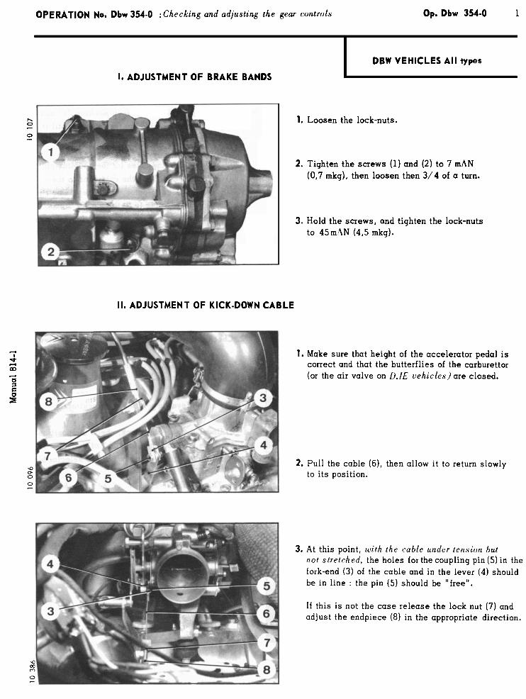
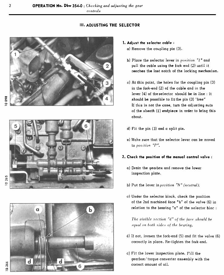
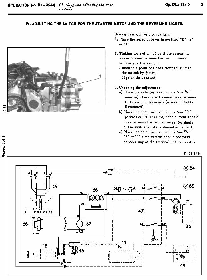
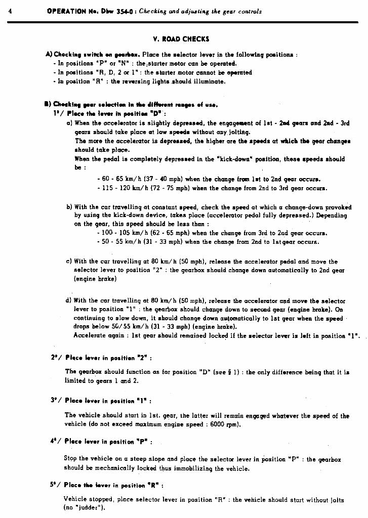
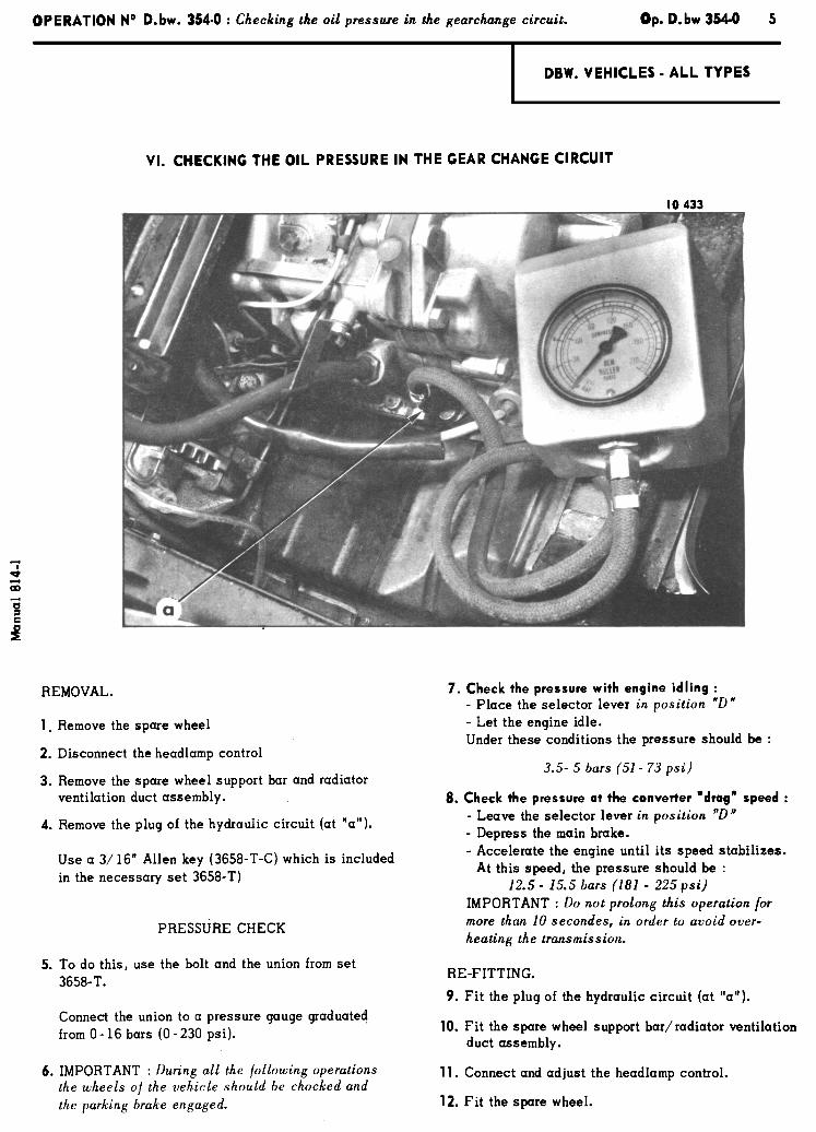
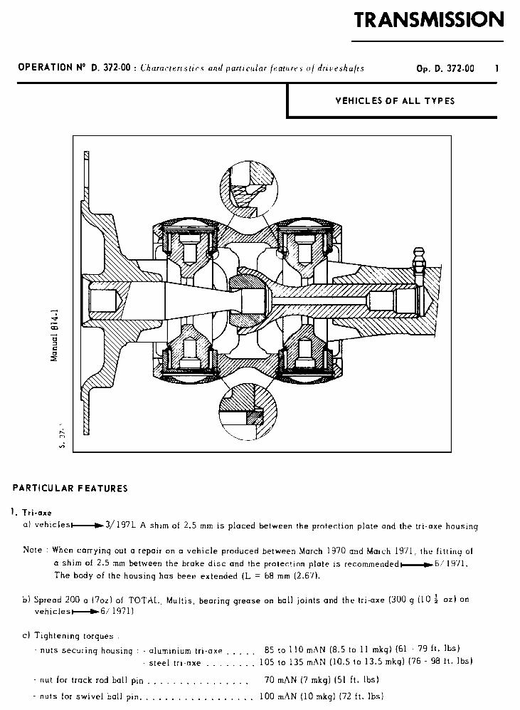
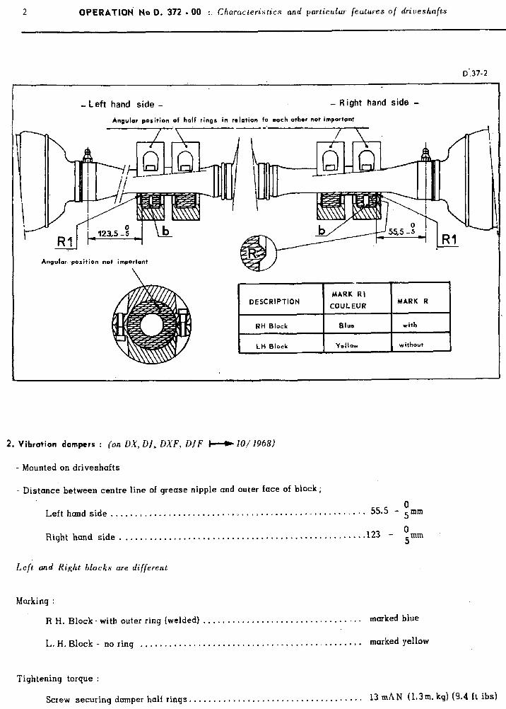
2 ClPERATIOti Na D. 372 - 00 : Characteristics and particular features of driveshafts
- Left hand side - - Right hand side -
Angular position of half rings in relation fo each other not important
/ \
637-2
Angular..position not important
LH Block Yellow without I
2. Vibration dampers : (on DX, DJ, DXF, DJF W iO/ ;968)
- Mounted on driveshafts
- Distance between centre line of grease nipple and outer face of block;
0 Lefthandside..........,....................~.~~.~~~~.,~~~.~..”.=* 55.5 - 5mm
Right hand side. .,..,.,.,,.... . . . . . . . . . . . . . . . . ..-.* “.... . . . . . . . ...123 0
- 5mm
Left and Right blocks are different
Marking :
R H. Block- with outer ring (welded) . . . . , . . , . . . . . . . . . . . . . . , . . . . . . . -. . marked blue
L. H. Block - no ring . . . . . . . . . . . . . . . . . . . . . . . -.. . . . . . . . . . . . I . . . . . . , . marked yellow
Tightening torque :
Screw securing damper half rings,. . . . . . . . . . . . . . . . . . . 1.. . . . . . =. . . . . , . 13 mRN (1.3m. kq) (9.4 ft ibs)
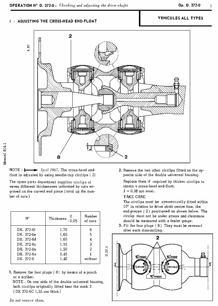
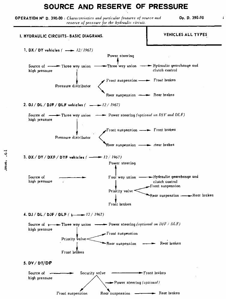
SOURCE AND RESERVE OF PRESSURE
OPERATION No R. 390.00 : Ch aracteristics and particular features of source and Op. D. 39040 reserve of pressure for the hydraulic circuit.
I: HYDRAULIC CIRCUITS- BASIC DIAGRAMS. VEHICLES ALL TYPES
,
1. DX/ DY vehicles ( ----z 121’1967) Power steering
Source of -Three way union t
-Three way union - Hydraulic gearchange and high pressure clutch control
Front suspension - Front brakes
Pressure distributor
< Rear suspension - Rear brakes
2. DJ / DL / PJF / DLF vehicles ( -12/ 1967)
Source of -Three way union - Power steering (optional on DJF and DLF) high pressure
J. .<
Front suspension - Front brakes
Pressure distributor
Rear suspension - dear brakes
3. DX/ RY/ DXF/ DYF vehicles ( - 12,/ 1967)
Power steering
t Source of high pressure .
Fou! way union -Hydraulic gearchange and
1
clutch control Front suspension
Priority valve ear suspension .-Rear brakes
4. DJ/DL/DJF/DLF( i----122/1967)
Source of ~-Three way union __)t Power steering (optional on Dj F / DL F)
high pressure
1 -=c
Front suspension Priority alve
a
Rear suspension L Rear brakes
Front br kes
5. DV/ DT/DP
Source of - Security valve -Front brakes high pressure
Power steering (optional)
v Rear brakes
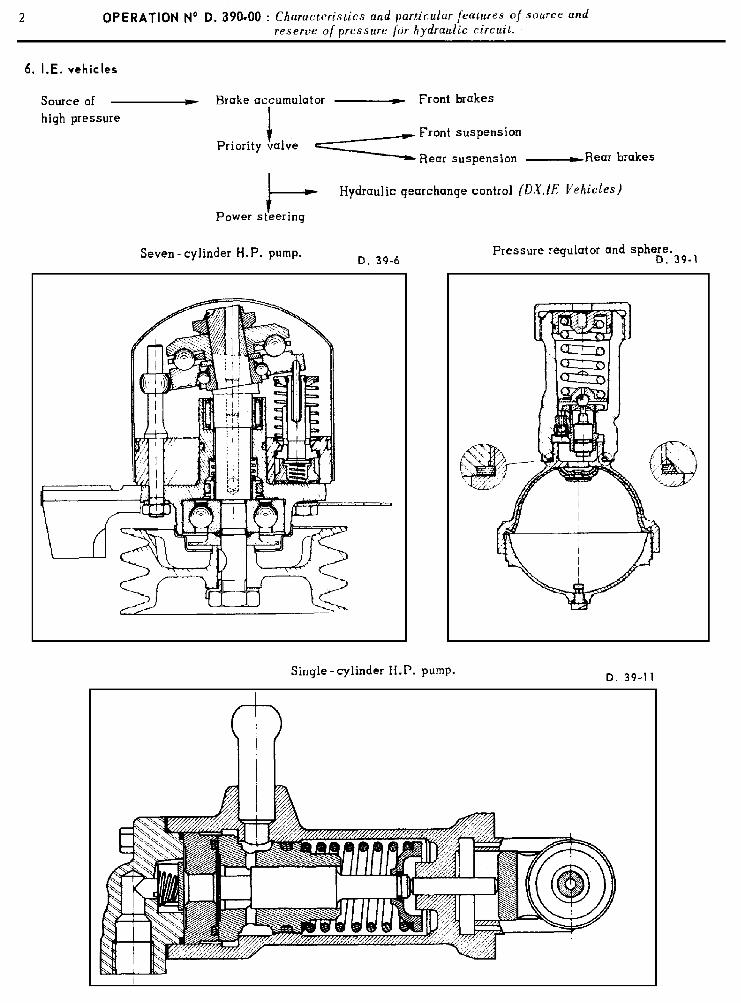
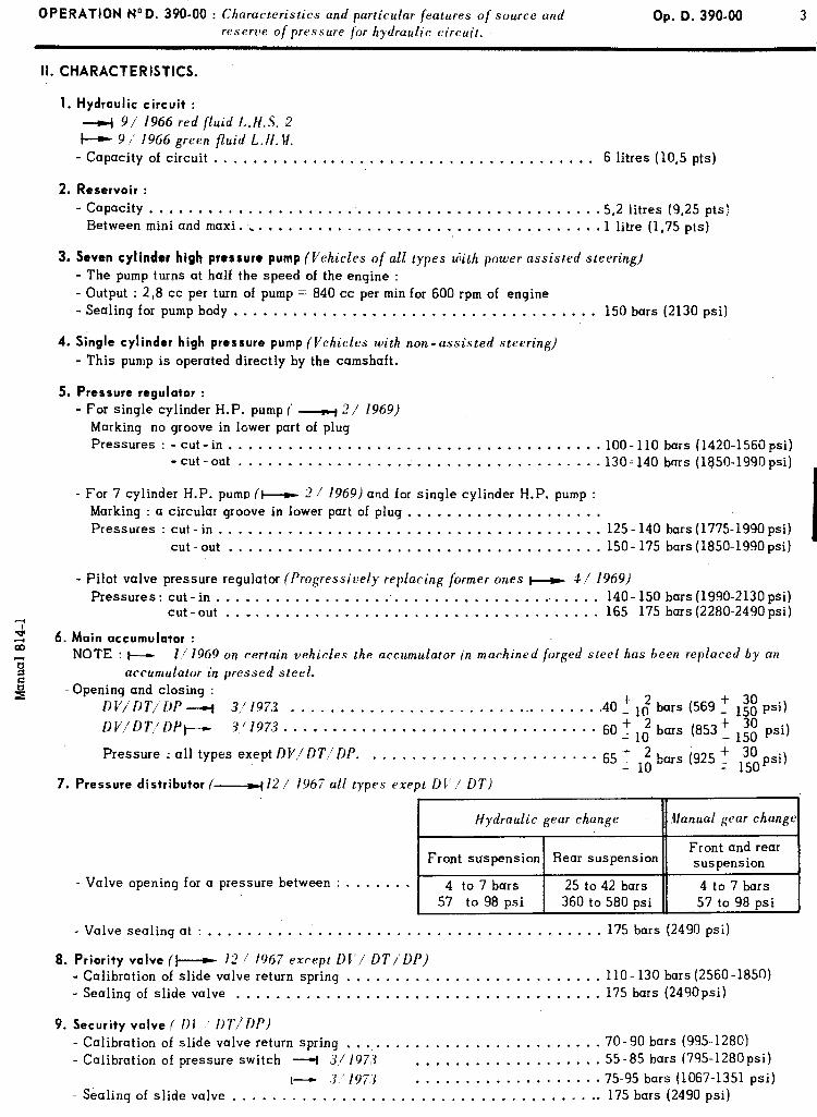
OPERATION NOD. 390-00 : Ch aracteristics and particular features of source and Op. D. 390-00 3 reserve of pressure for hydraulic circuit.
II. CHARACTERISTICS.
1. Hydraulic circuit :
4 9/ 1966 red fluid L.H.S. 2
w 9 1 1966 green fluid L. H. W. - Capacity of circuit . . . . . . . . . . . . . . . . . . . , . . , . . . . . . . . . . . . . . . . 6 litres (lo,5 pts)
2. Reservoir :
- Capacity . . . . . . . . . , . . . . . . . . . . . . . . . . . . . . . . . . . . . . . . . . . . . .5,2 litres (9,25 pts) Between mini and maxi. . . . . . . . . . . . . . . . . . . . . . . . . . . . . . . . . . . . . 1 litre (1,75 pts)
3. Seven cylinder high pressure pump (Vehicles of all types ujith power assisted steering) - The pump turns at half the speed of the engine : - Output : 2,8 cc per turn of pump = 840 cc per min for 600 rpm of engine - Sealing for pump body . . . . . . . . . . . . . . . . . . . . . , . . . . , . . . . . . . . . . 150 bars (2130 psi)
4. Single cylinder high pressure pump (Vehicles with non-assisted steering)
- This pump is operated directly by the camshaft.
5. Pressure regulator :
- For single cylinder H.P. pump (’ _y 2/ 1969) Marking no groove in lower part of plug Pressures : - cut-in . . . . . . . . . . . . . . . . . . . . . . . . . . . . . . . . . . . . . . lOO- 110 bars (1420-1560psi)
-cut-out.....................,.,.,.,,........ 130; 140 bars (1850-199Opsi)
- For 7 cylinder H.P. pump (‘w 2 1 1969) and for single cylinder H.P. pump : Marking : a circular groove in lower part of plug . . . . . . . . . . . . . . . . . . . . Pressures : cut - in , . . . . . . . . . . . . . . . . . . . . . . . . . . . . . . . . . . . . . . 125- 140 bars
cut-out . . . . . . . . . . . . . . . . . . . . . . . . . . . . . . . . . . . . . . 150-175 bars (1775-1990 psi) (1850-1990 psi)
- Pilot valve pressure regulator (Progressively replacing former ones w 1/ 1969) Pressures : cut - in . . . . . . . . . . . . . . . . . . . . . . . . . . . . . . . . . . . . . . . . 140- 150 bars
cut-out . . _ . . . . . . . . . . . . . . . . . . . . . . . . . . . . . . . . . . . 165- 175 bars T; 2 6. Main accumulator :
1990-2130 psi) 2280-2490 psi)
u
; NOTE : I--- l/1969 on certain vehicles the accumulator in machined forged steel has been replaced by an
2 accumulator in pressed steel.
2 -Opening and closing : DV/DT/DP-+ 3/197.X . . . . . . . . . . . . . . . . . . . . . . . . . . . . . . . . .40 ‘1: bars (569 T 1:: psi)
DV/DT,‘DPI- S//973. m . v . . - . . . . . . . . . . . . . . . . . . . v . . . . . 60 ,’ 1t bars (853: lzi psi)
Pressure : all types exept DV,/DT.‘DP. . . . . . . . . . . . . . . . . . . . . . . . 65 + 2 bars (925 t 30 - 10 - 15pi)
7. Pressure distributor /---I 12 / 1967 all types exept DI’i UT)
- Valve opening for a pressure between : . . . . . . .
Hydraulic gear change
4 to 7 bars
. Valve sealing at : ........................................ 175 bars (2490 psi)
8. Priority valve (+-w 12! 1967 except DC’/ DT/‘DP) - Calibration of slide valve return spring .......................... llO- 130 bars (2560-1850) - Sealing of slide valve ..................................... 175 bars (249Opsi)
9. Security valve ( Dl ’ i)T.!DP) . Calibration of slide valve return spring .......................... 70-90 bars (995-1280) - Calibration of pressure switch + J./l973 ................... 55-85 bars (795-1280psi)
I- .i’/197.3 ................... 75-95 bars (1067-1351 psi) - Sealing of slide valve ...................................... 175 bars (2490 psi)
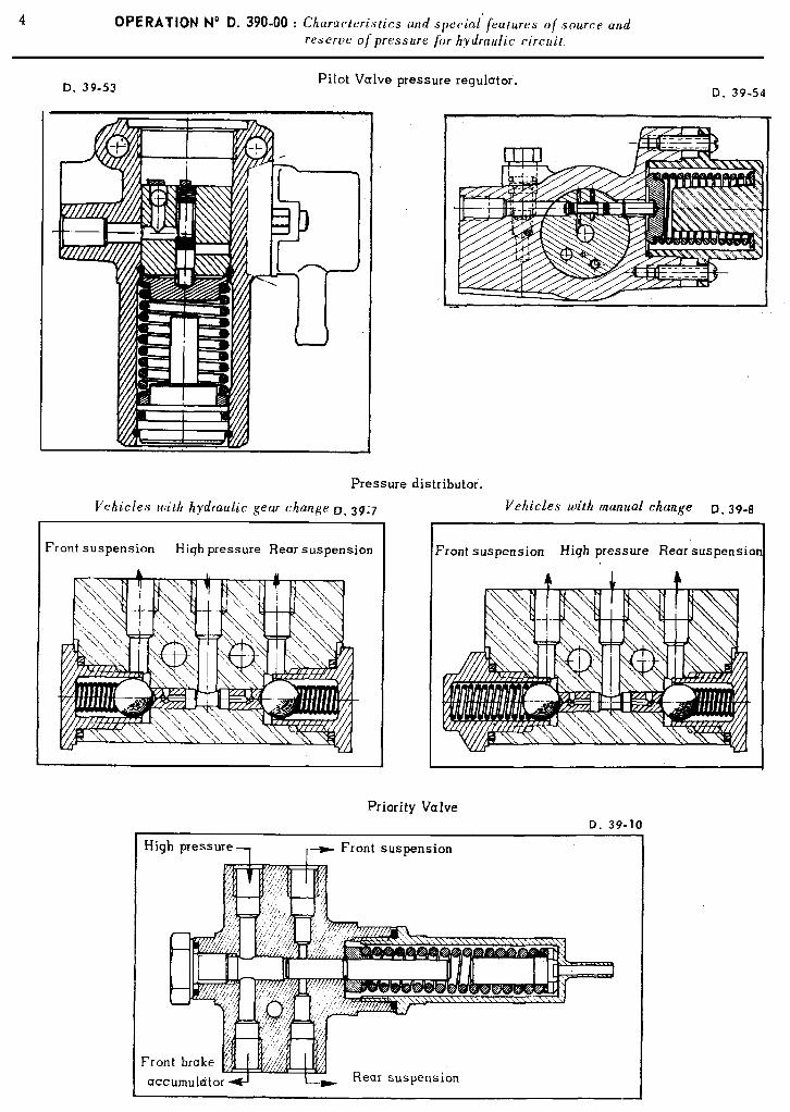
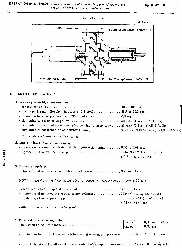
OPERATION N“ D.‘35’0-00 : Ch aracteristics and special featrtres of source and reserve of pressure for hydraulic circuit.
Op. D. 390.00 5
Security valve D. 39-5
Front suspension (corrector)
Front brakes (control Val Rear suspension (corrector).
III. PARTICULAR FEATURES.
1. Seven cylinder high pressure pump :
- tension for belts . , , . . . . . . . . . . . . . . . . . . . . . . . . . , . . . . 40 kg. (88 lbs)
- piston push rods : (lenghs : in steps of 0,l mm.) . , . . . . . . . . . , 28,r3 to 30,s mm.
- clearance between piston crown (TDC) and valve. . . . . . . . . . . . r3,5 mm. - tightening of nut on drive pulley . . . . . . . . . . . . . . . . . . . . . . 4tl mhN (4 m.kg) (29 ft. lbs)
- tightening of nuts and screws securing bearing to pump body . . . . 35 m:\N (3,5 m-kg) (25,3 ft. lbs) - tightening of securing nuts on gearbox housing . . . . . , . , , . . . . 35 -40 m:!N (3,5 -4 m. kg)(‘25,3 to2gft lbs)
Renew all seals after each dismantling.
2. Single cylinder high pressure pump :
‘: - clearance between pump body and plug (before tightening) . . . . . . 0,05 to 0,09 mm.
v z - tightening of screws securing plug . , . . . . . . . . , . . . . . . , . . 17to19mhN(1,7to1,9m.kg)
ii (12,3 to 13,7 ft. Ibs)
2 s 3. Pressure regulator :
- shims adjusting pressure regulator : thicknesses . . . . . . . , . . , 0,25 and 1 mm.
NOTE : ,I thickness of 1 mm brings abou.t a change irr pressure of. . 10 bars (150 psi)
- clearance between cup and cut - in ball . . . . . . . . . . . . . . . . . . 0,3 to 0,4 mm.
- ti,qhtening of nut securing control piston cylinder. . . . . . . . , . . . 30mzN (3 m.kq) (22 ft. lbs)
- tiqjltening of nut supporting plug . . . . . . . . . . . . . . . . . . . . . . 170to200m~IN (17 to20m.kgf
- IZbicai.6 threads with hydraulic fluid.
(122 to 144 ft. Ibs)
4. Pilot valve pressure regulator. s cut in‘--. . .
- . . adjusting shims : thickness . . . . . . . . , . . . . . -5. : 0,30 and 0,70 mm
. . . . . . . . * . I cut out . * 0,30 mm
- cut in chamber : 1 0,30 mm shim brings about a change in pressure of . . . . 3 bars (43 psi) approx.
- cut out chamber : 1 0,70 mm shim brings about;a’&ange in pressure of . . . 7 bars (100 psi) approx. .
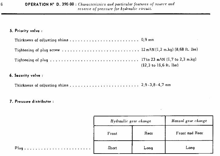
6 OPERATION No D. 390.00 : Characteristics and particular features of .source and reserve of pressure for hydraulic circuit.
5. Priority valve :
Thickness of adjusting shims . . . . . . . . . . . . . . . . . . . . . . . . . 0,9 mm
Tightening of plug screw . . . . . . . . . . . . . . . . . . . . . . . . . . . . 12 mAN (12 m.kg) (8,68 ft. Ibs)
Tightening of plug . . . . . . . . . . . . . . . . . . . . . . . . . . . . . . . . 17 to 23 mAN (1,7 to 2,3 m.kg) (12,3 to 16,6 ft. lbs)
6. Security valve :
Thickness of adjusting shims . . . . . . . . . . . . . . . . . . . . . . . . . 2,9 -3,8 -4,7 mm
7. Pressure distributor :
Plug . . . . . . . . . . . . . . . . . . . . . . . .
Hydraulic gear change
Front Rear
Short Long
Manual gear change
Front and Rear
Long
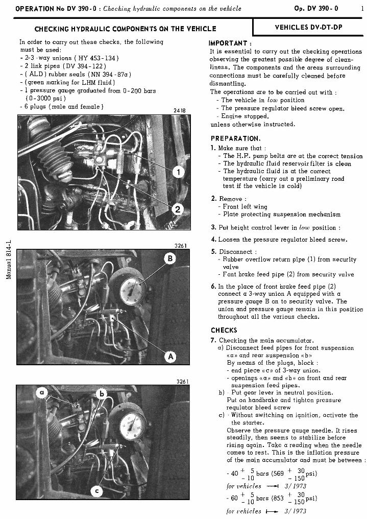
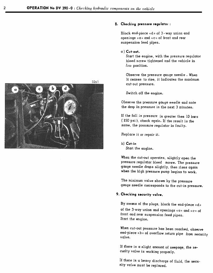

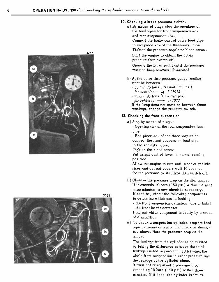
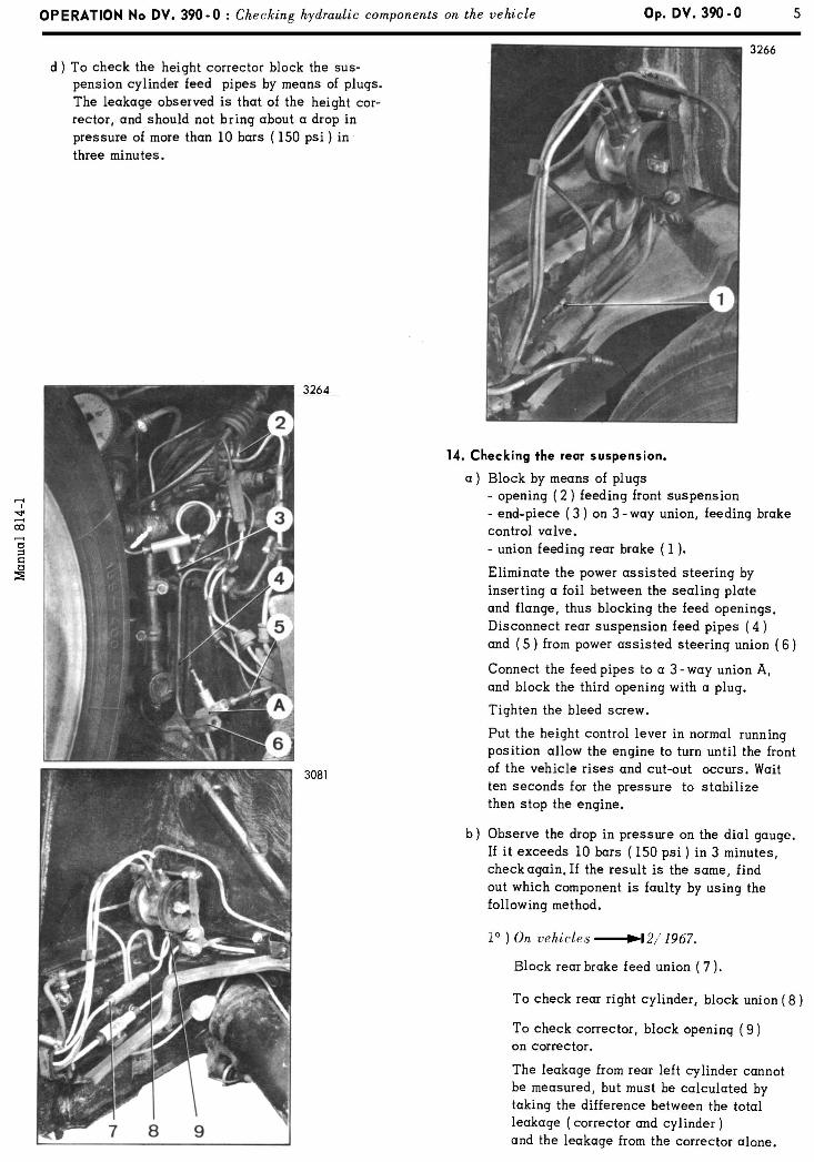
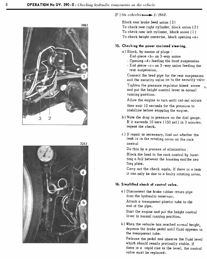
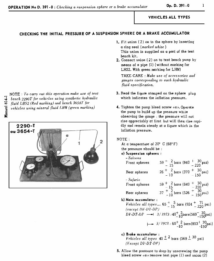
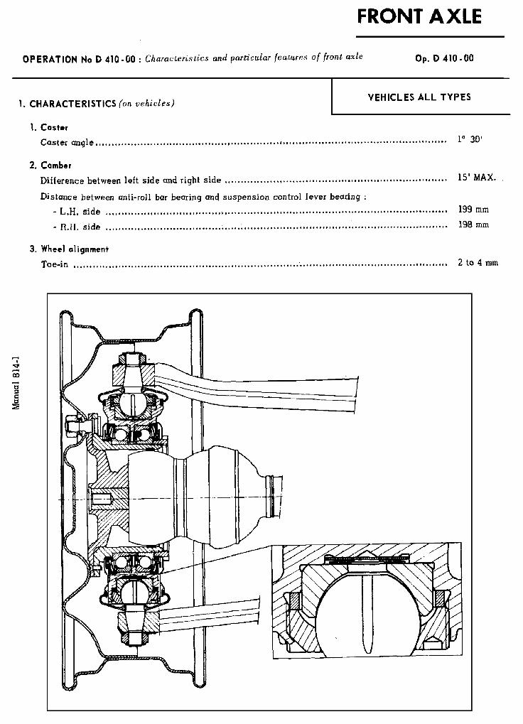
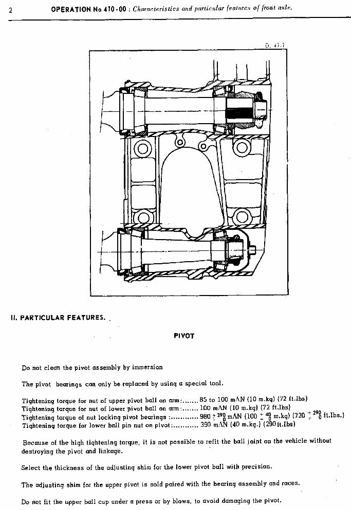
2 OPERATION No 410-00 : Ch aracteristics and particular featwes of front axle.
II. PARTICULAR FEATURES. ,
PIVOT
Do not clean the pivot assembly by immersion
The pivot bearings can only be replaced by using a special tool.
Tightening torque for nut of upper pivot ball on arm:.......8 5 to 100 mAN (10 m.kg) (72 ft.lbs) Tightening torque for nut of lower pivot ball on arm: 100 mhff (10 m.kg) (72 ft.Ibs) Tightening torque of nut locking pivot bearings : ................... 980 T api mAN (100 ‘, 4t m.kg) (720 T 29i ft.lbs.) Tightening torque for lower ball pin nut on pivot: ........... 390 mAN (40 m.kg.) (290ftJbs)
Because of the high tightening torque, it is not possible to refit the ball joint on the vehicle without destroying the pivot and linkage.
-Select the thickness of the adjusting shim for the lower pivot ball with precision.
The adjusting shim for the upper pivot is sold paired with the bearing assembly and races.
Do not fit the upper ball cup under a press or by blows, to avoid damaging the pivot,
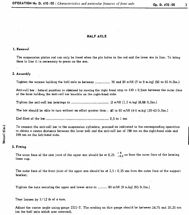
OPERATION No D. 410 - 00 : Characteristics and particular features o/ {rant axle Op. D. 410’.00 3
HALF AXLE
1. Removal
The suspension piston rod can only be freed when the pin holes in the rod and the lever are in line. To bring them in line it is necessary to press on the arm.
2. Assembly
Tighten the screws holding the half-axle to between .,...,,..,.,. 70 and 90 mAN (7 to 9 m.kg) (50 to 65 ft.Ibs.)
Anti-roll bar : lateral position is obtained by moving the right hand stop to 110 + 0,Smm between the outer face of the boss holding the anti-roll bar knuckle on the right-hand side.
Tighten the anti-roll bar bearings to .*...*.*...*..................~.. 12 mAN (1,2 m.kg) (8,68 ft.Ibs.)
The bar should be able to turn without an effort greater than : 40 to 60 mAN (4-6 m.kg) (29-43 ft.Ibs.)
End float of the bar . . . . . . . . . . . . . . . . . . . . . . . . . . . . . . . . . . . . . . . . . . . . . . . . . . . . . . . 0,s to 1 mm
7 * To connect the anti-roll bar to the suspension cylinders, proceed as indicated in the corresponding operation 4 OD to obtain a centre distance between the lever ball and the anti-roll bar of 198 mm on the right-hand side and
199 mm on the left-hand side.
3. Fitting
The outer face of the rear joint of the upper arm should be at 6,25 to _ u 5 mm from the outer face of the bearing ,
inner cup,
The outer face of the front joint of the upper arm should be at 2,s + 0,25 mm from the outer face of the support bracket.
Tighten the nuts securing the upper and lower arms to : ,...... 90 mAN (9 m.kg) (65 ft.Ibs.)
Then .loosen by l/ 12 th of a turn.
Adjust the caster angle using gauge 2321-T. The reading on this gauge should be between 24.75 and 25.25 mm (on the half axle which was removed).
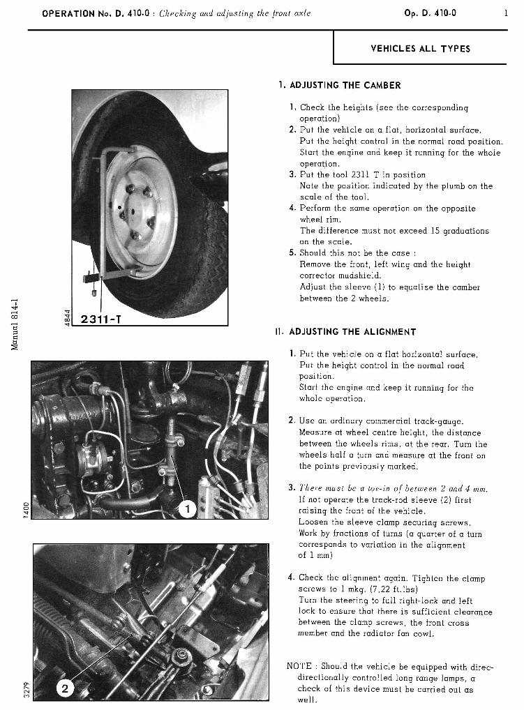
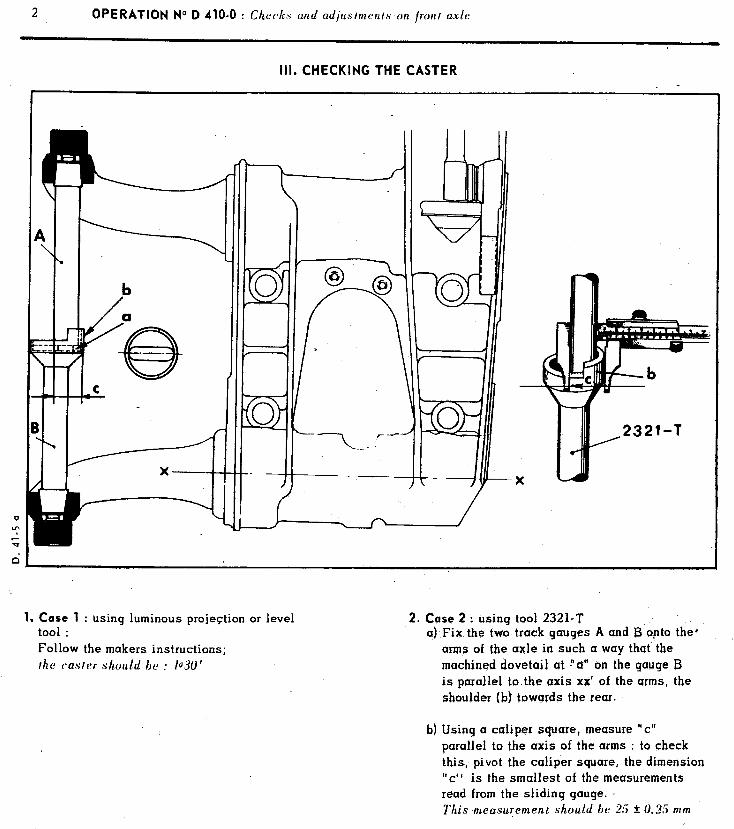
2 OPERATION No D 410-O : Che&s and d’ ‘I a ps mrnls an ljonl axle
Ill. CHECKING THE CASTER
1. Case 1 : using luminous projection or level too1 : Follow the makers instructions; /he c-aslrr should he : 1030’
2. Case 2 : using tool 2321-T a) Fix the two track gauges A and B‘opto the*
arms of the axle in such a way that’ the machined dovetail at !‘cr” on the gauge B is parallel to.the axis xx’ of the arms, the shoulder (b) towurds the rear.
b) Using a caliper square, measure “cl’ parallel to the axis of the arms : to check this, pivot the caliper square, the dimension “c” is the smallest of the measurements read from the sliding gauge.
This measurement should be 2.5 2 0.15 mm
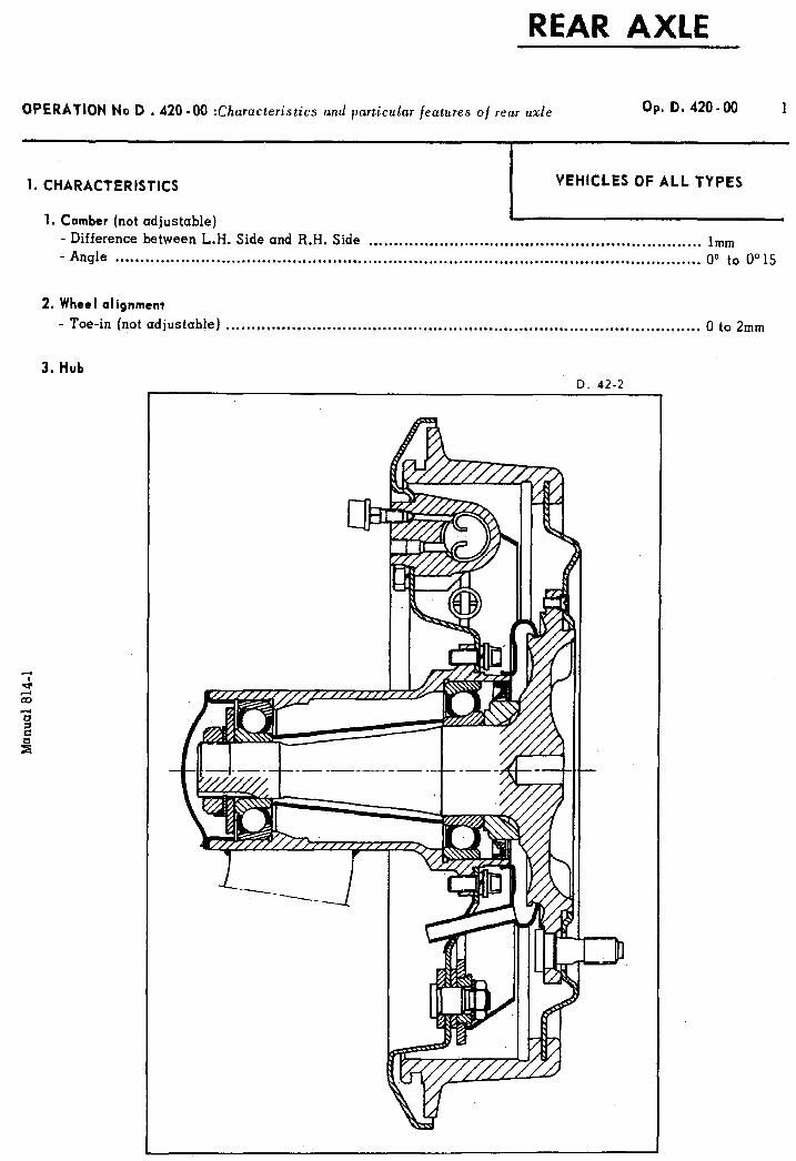
REAR AXLE
OPERATION No D .420-00 :Ch aracteristics and particular features of rear axle Op, D. 420-00
1. CHARACTERISTICS VEHICLES OF ALL TYPES
1. Camber (not adjustable) I
- Difference between L.H. Side and R.H. Side . . . . . . . . . . . . . . . . . . . . . . . . . . . . . . . . . . . . . . . . . . . . . . . . . . . . . . . . . . . . . . . . . . lmm - Angle . ..~....~..........................~.~.....~....~~...........~.....~.......~~.................~...~.......~....~.~.. 00 to 0” 15
2. Wheel alignment - Toe-in (not adjustable) . . . . . . ..~.....~.....................................~......................................... 0 to 2mm
3. Hub D. 42-2
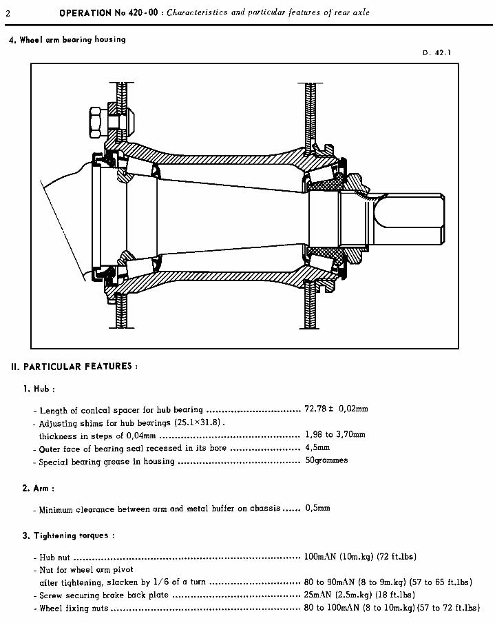
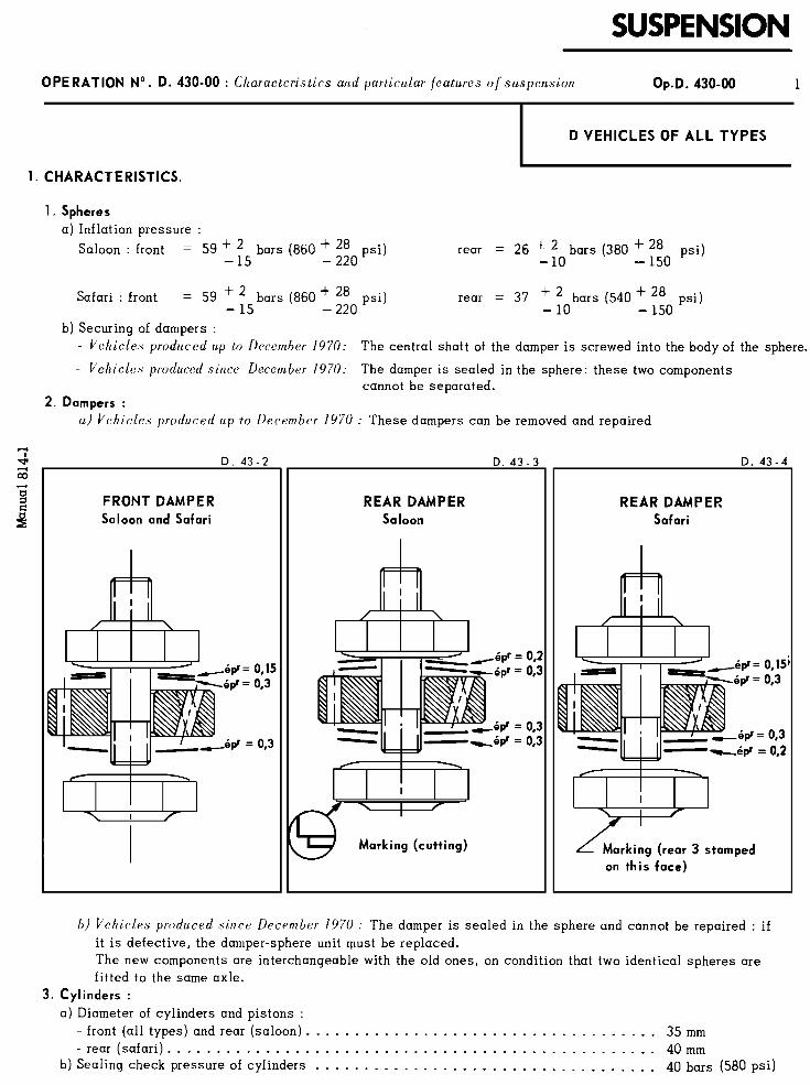
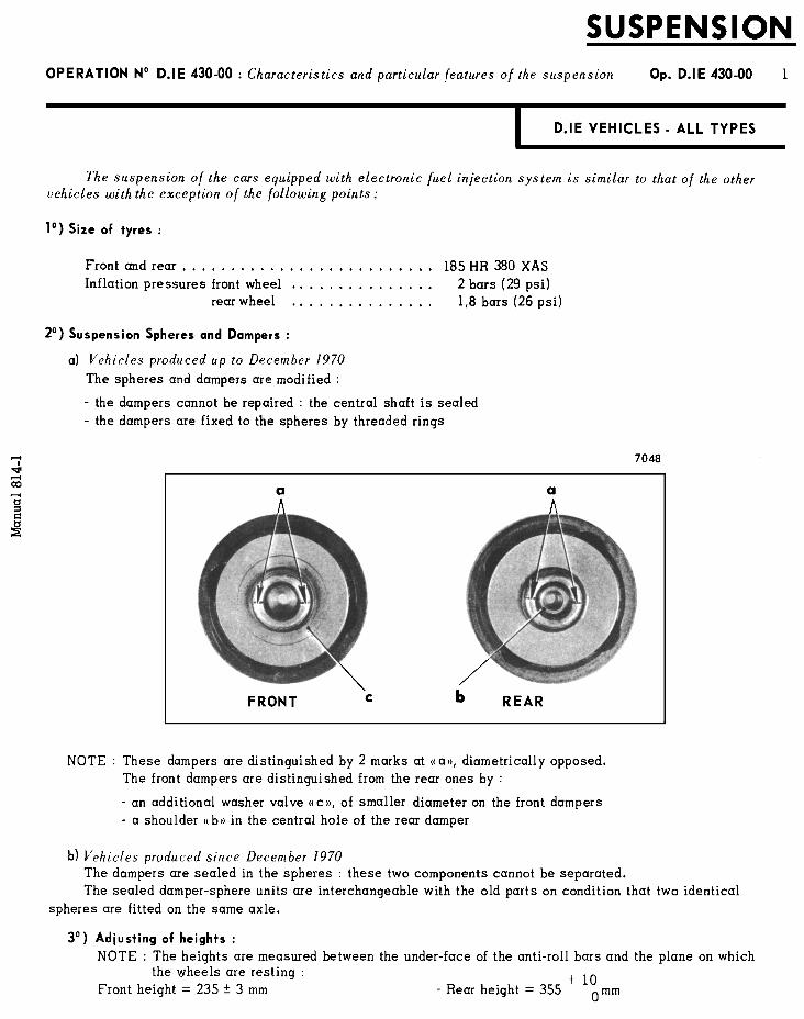
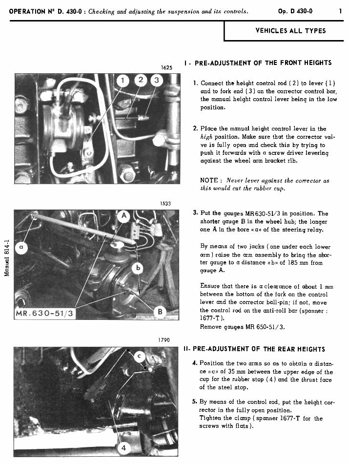
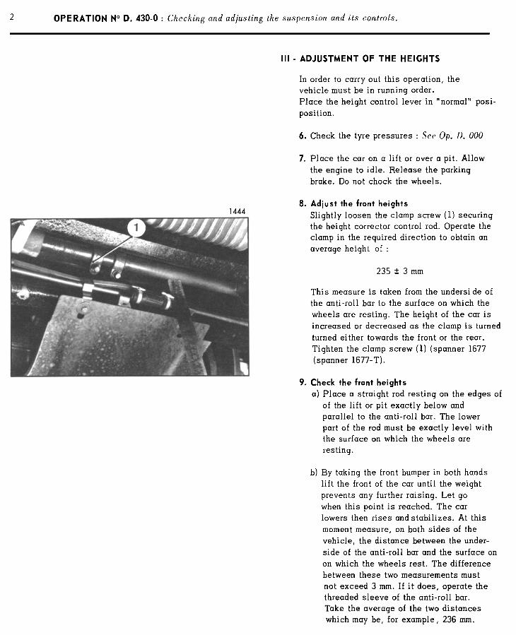
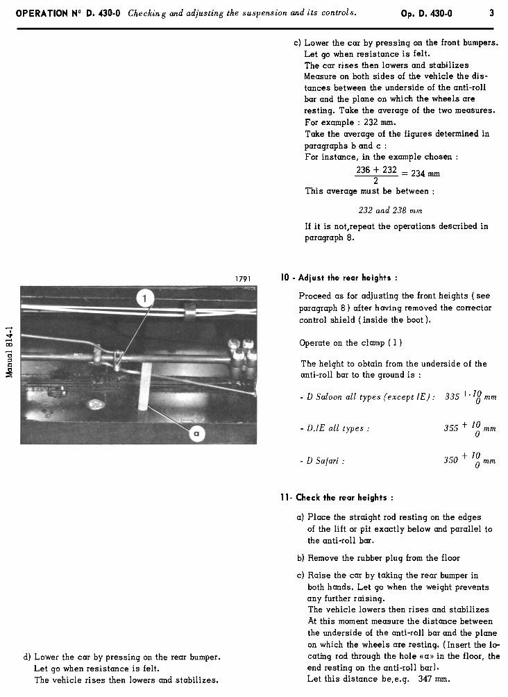
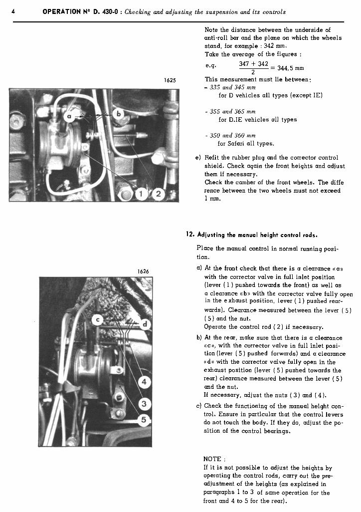
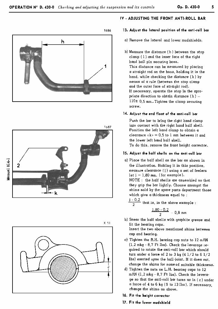
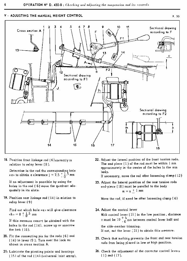
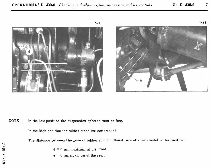
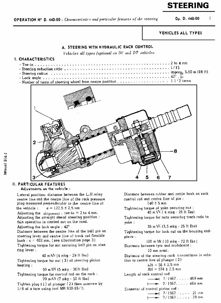
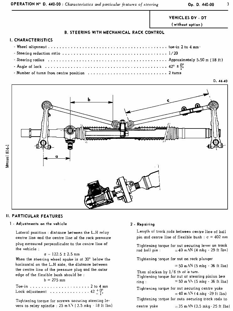

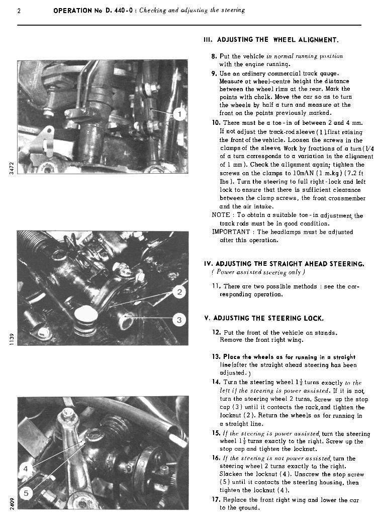
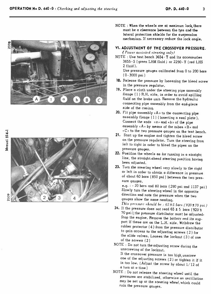
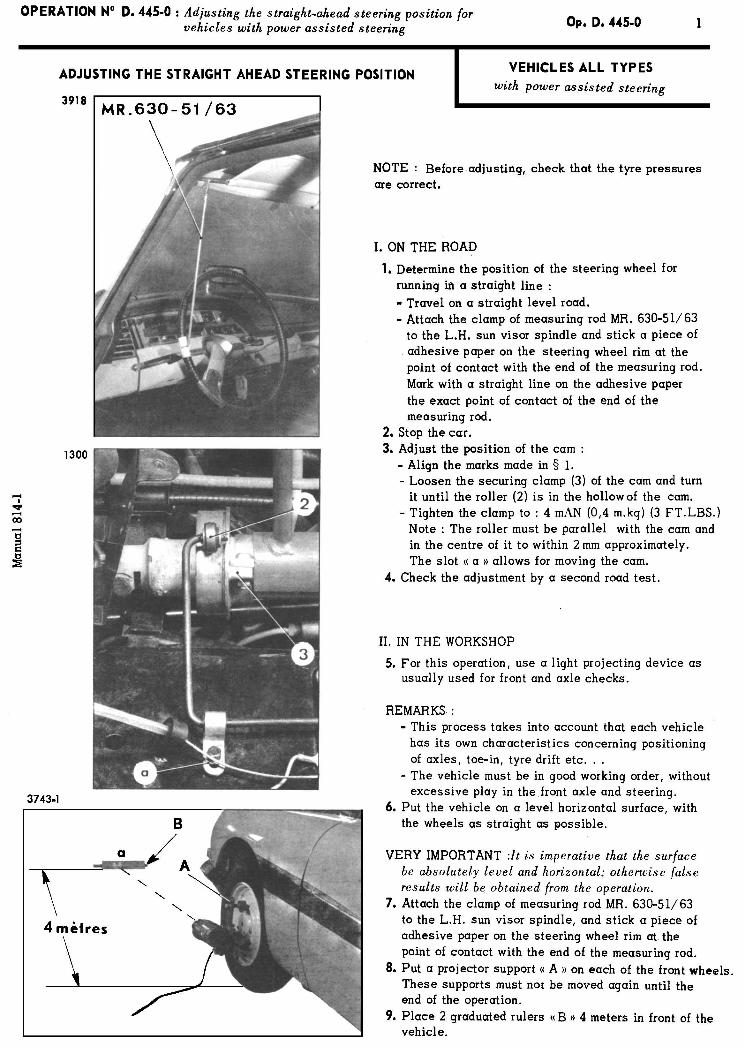
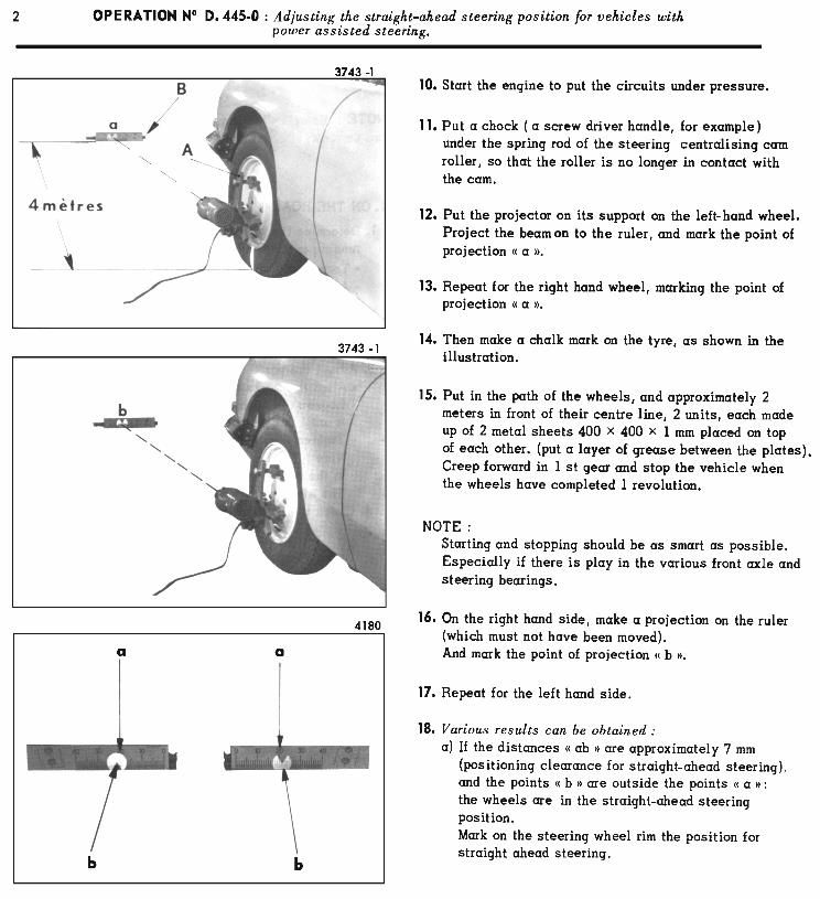
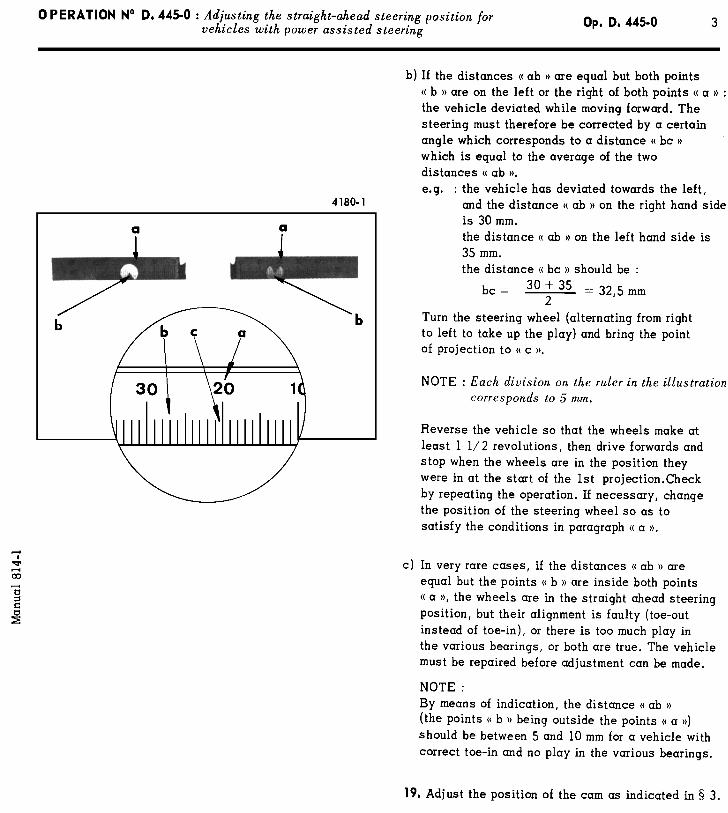
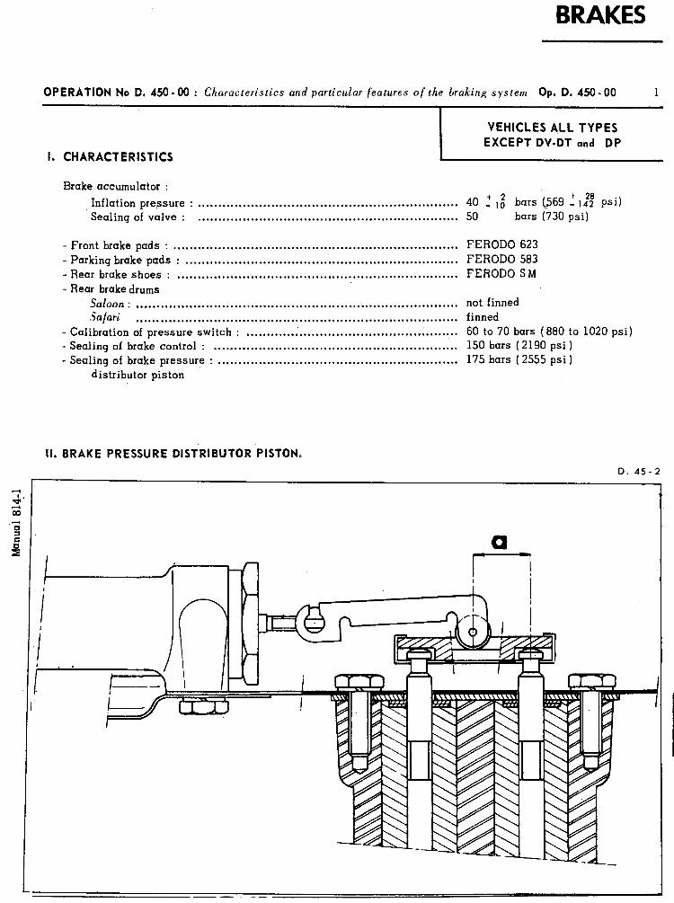
BRAKES
OPERATION No D. 450-00 : Ch aracteristics and particular features of the braking system Op. D. 450 - 00
I, CHARACTERISTICS
Brake accumulator :
Inflation pressure : . . . . . . . . . . . . . . . . . . . . . . . . . . . . . . . . . . . . . . . . . . . . . . . . . . . . . . . . . . . . . . . . 40 -‘,f bars @69 ,’ 1:: psi) Sealing of valve : . . . . . . . . . . . . . . . . . . . . . . . . . . . . . . . . . . . . . . . . . . . . . . . . . . . . . . . . . . . . . . . . 50 bars (730 psi)
- Front brake pads : ...................................................................... - Parking brake pads : ................................................................... - Rear brake shoes : ..................................................................... - Rear brake drums
Saloon : ............................................................................... Salari ...............................................................................
- Calibration of pressure switch : .................................................... - Sealing of brake control : ............................................................ . Sealing of brake pressure : ...........................................................
distributor piston
FERODO 623 FERODO 583 FERODO SM
not finned finned 60 to 70 bars (880 to 1020 psi) 150 bars (2190 psi) 175 bars (2555 psi)
II. BRAKE PRESSURE DISTRIBUTOR PISTON.
D. 45-2
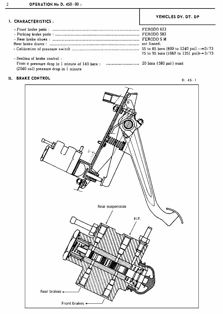
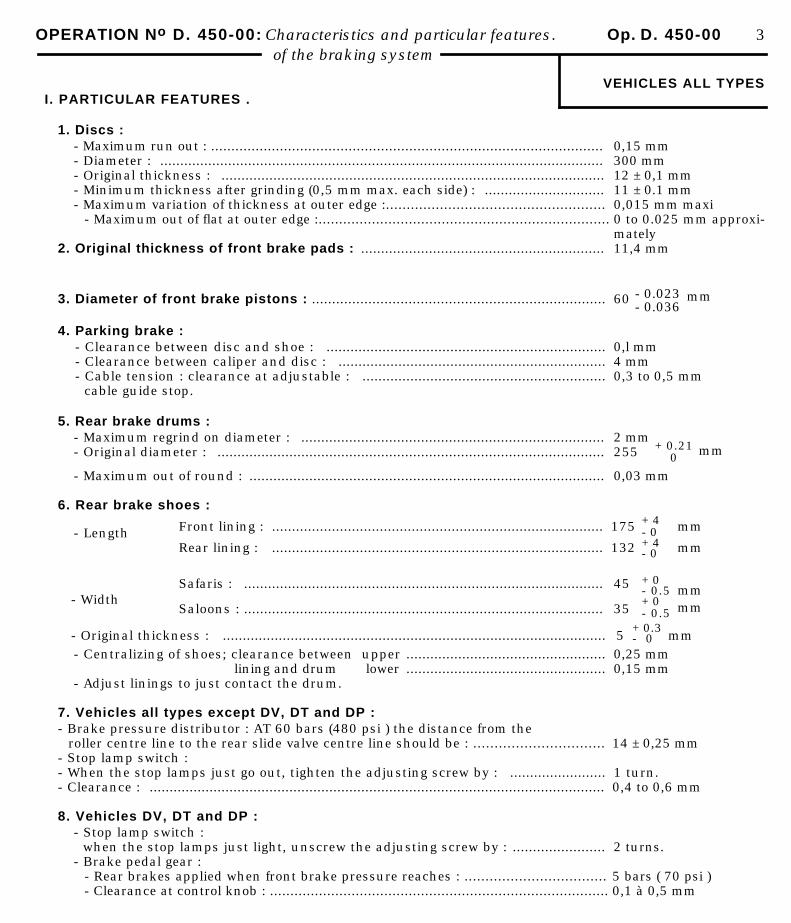
OPERATION No D. 450-00: Characteristics and particular features. Op. D. 450-00 3of the braking system
VEHICLES ALL TYPES I. PARTICULAR FEATURES .
1. Discs :- Maximum run out : ................................................................................................. 0,15 mm- Diameter : ............................................................................................................... 300 mm- Original thickness : ................................................................................................ 12 ± 0,1 mm- Minimum thickness after grinding (0,5 mm max. each side) : .............................. 11 ± 0.1 mm- Maximum variation of thickness at outer edge :..................................................... 0,015 mm maxi
- Maximum out of flat at outer edge :....................................................................... 0 to 0.025 mm approxi-mately
2. Original thickness of front brake pads : ............................................................. 11,4 mm
3. Diameter of front brake pistons : ......................................................................... 60
- 0.023- 0.036
mm
4. Parking brake :- Clearance between disc and shoe : ...................................................................... 0,l mm- Clearance between caliper and disc : ................................................................... 4 mm- Cable tension : clearance at adjustable : ............................................................. 0,3 to 0,5 mm
cable guide stop.
5. Rear brake drums :- Maximum regrind on diameter : ............................................................................ 2 mm- Original diameter : ................................................................................................. 255 + 0.21
0mm
- Maximum out of round : ......................................................................................... 0,03 mm
6. Rear brake shoes :
- Length
- Width
Front lining : ................................................................................... 175
Rear lining : ................................................................................... 132
Safaris : .......................................................................................... 45
Saloons : .......................................................................................... 35
+ 4- 0+ 4- 0
+ 0- 0.5+ 0- 0.5
mm
mm
mmmm
- Original thickness : ................................................................................................ 5 + 0.3- 0 mm
- Centralizing of shoes; clearance between upper .................................................. 0,25 mm lining and drum lower .................................................. 0,15 mm- Adjust linings to just contact the drum.
7. Vehicles all types except DV, DT and DP :- Brake pressure distributor : AT 60 bars (480 psi ) the distance from the
roller centre line to the rear slide valve centre line should be : ............................... 14 ± 0,25 mm- Stop lamp switch :- When the stop lamps just go out, tighten the adjusting screw by : ........................ 1 turn.- Clearance : .................................................................................................................. 0,4 to 0,6 mm
8. Vehicles DV, DT and DP :- Stop lamp switch :
when the stop lamps just light, unscrew the adjusting screw by : ....................... 2 turns.- Brake pedal gear :
- Rear brakes applied when front brake pressure reaches : .................................. 5 bars ( 70 psi )- Clearance at control knob : ................................................................................... 0,1 à 0,5 mm
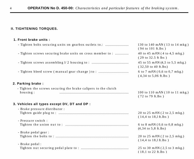
4 OPERATION No D. 450-00: Characteristics and particular features of the braking system.
II. TIGHTENING TORQUES.
1. Front brake units :
- Tighten bolts securing units on gearbox outlets to.: ........................ 130 to 140 mΛN ( 13 to 14 mkg )( 94 to 101 ft.lbs )
- Tighten screws securing brake units on cross member to : .............. 40 to 45 mΛN ( 4 to 4,5 mkg.)( 29 to 32.5 ft lbs )
- Tighten screws assembling l/2 housing to : ...................................... 45 to 55 mΛN (4,5 to 5,5 mkg.)( 32,50 to 40 ft.lbs)
- Tighten bleed screw ( manual gear change ) to : ............................... 6 to 7 mΛN ( 0,6 to 0,7 mkg.)( 4,34 to 5,06 ft.lbs )
2. Parking brake :
- Tighten the screws securing the brake calipers to the clutchhousing : ....................................................................... 100 to 110 mΛN ( 10 to 11 mkg.)
( 72 to 79 ft.lbs )
3. Vehicles all types except DV, DT and DP :
- Brake pressure distributor :Tighten guide plug to : ........................................................................ 20 to 25 mΛN ( 2 to 2,5 mkg.)
( 14,4 to 18,l ft.lbs )- Pressure switch :Tighten the union nut to : ................................................................. 6 to 8 mΛN ( 0,6 to 0,8 mkg.)
(4,34 to 5,8 ft.lbs)- Brake pedal gear :Tighten the bolts to : ........................................................................... 20 to 25 mΛN ( 2 to 2,5 mkg.)
( 14,4 to 18,l ft.lbs )- Brake pedal :Tighten nut securing pedal plate to : ................................................. 25 to 30 mΛN ( 2,5 to 3 mkg.)
( 18,1 to 22 ft.lbs )
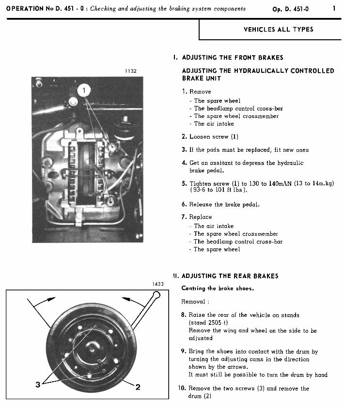
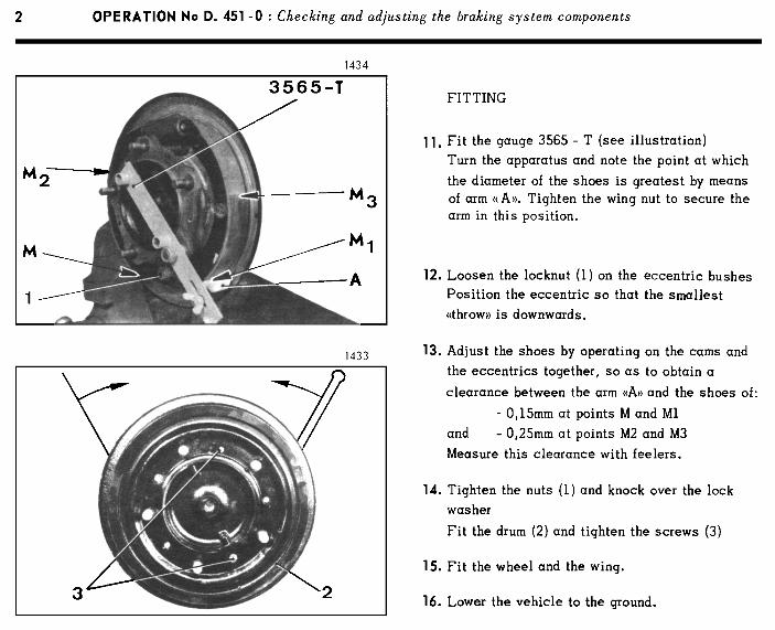
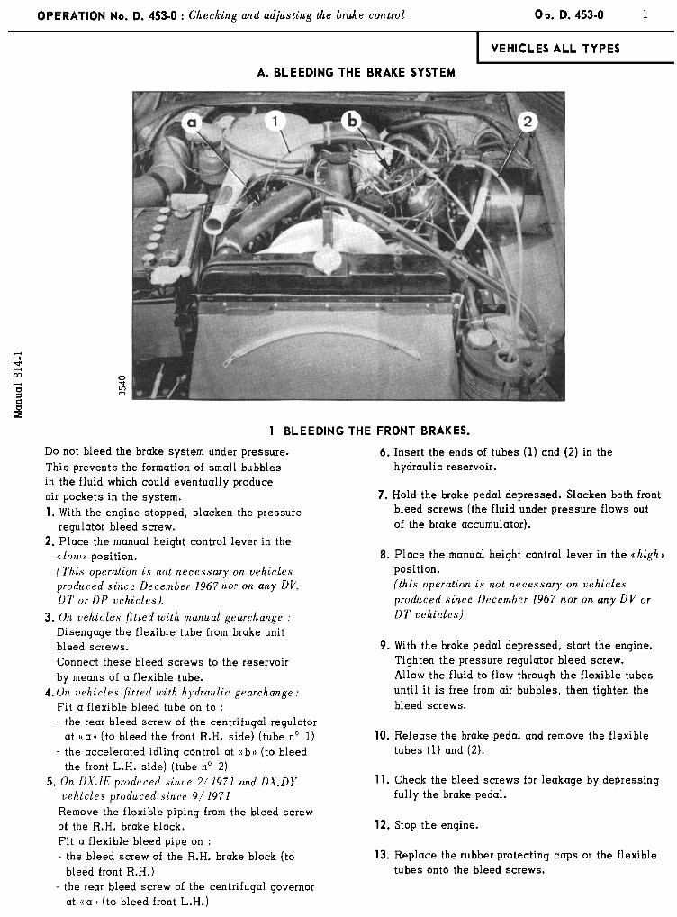
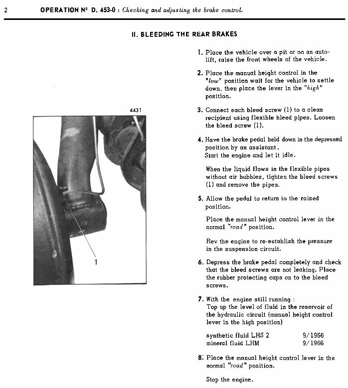
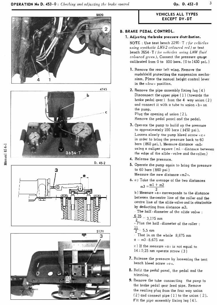
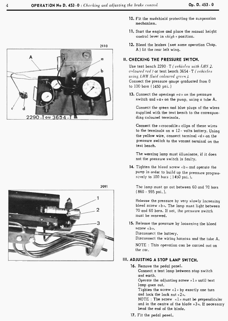
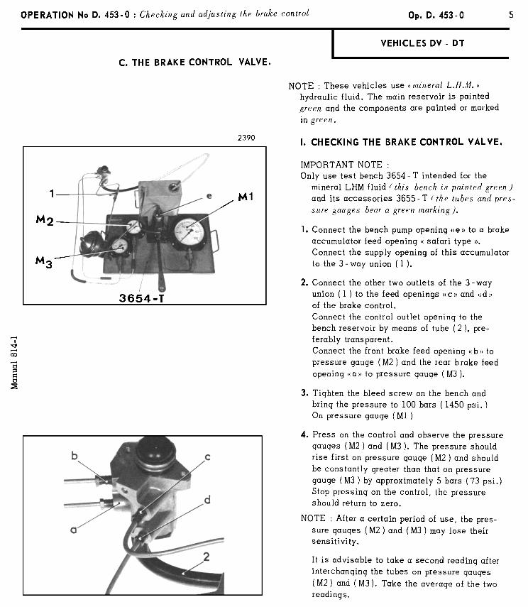
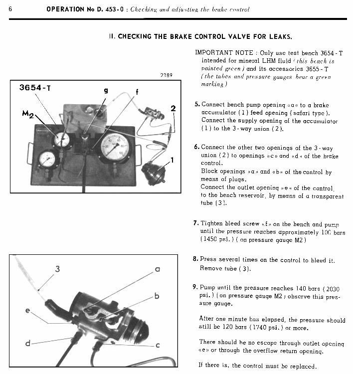
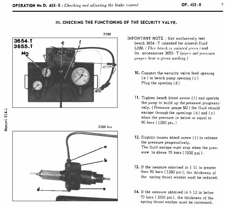
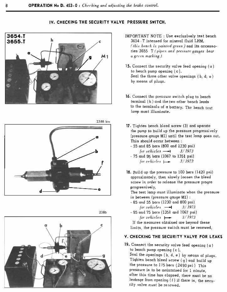
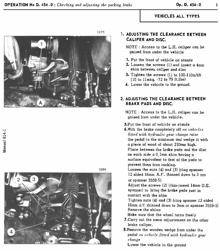
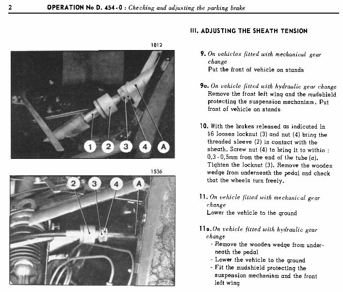
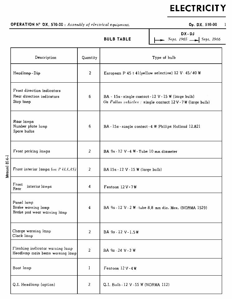
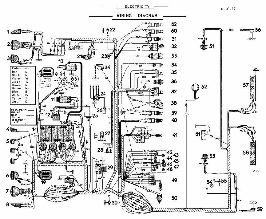
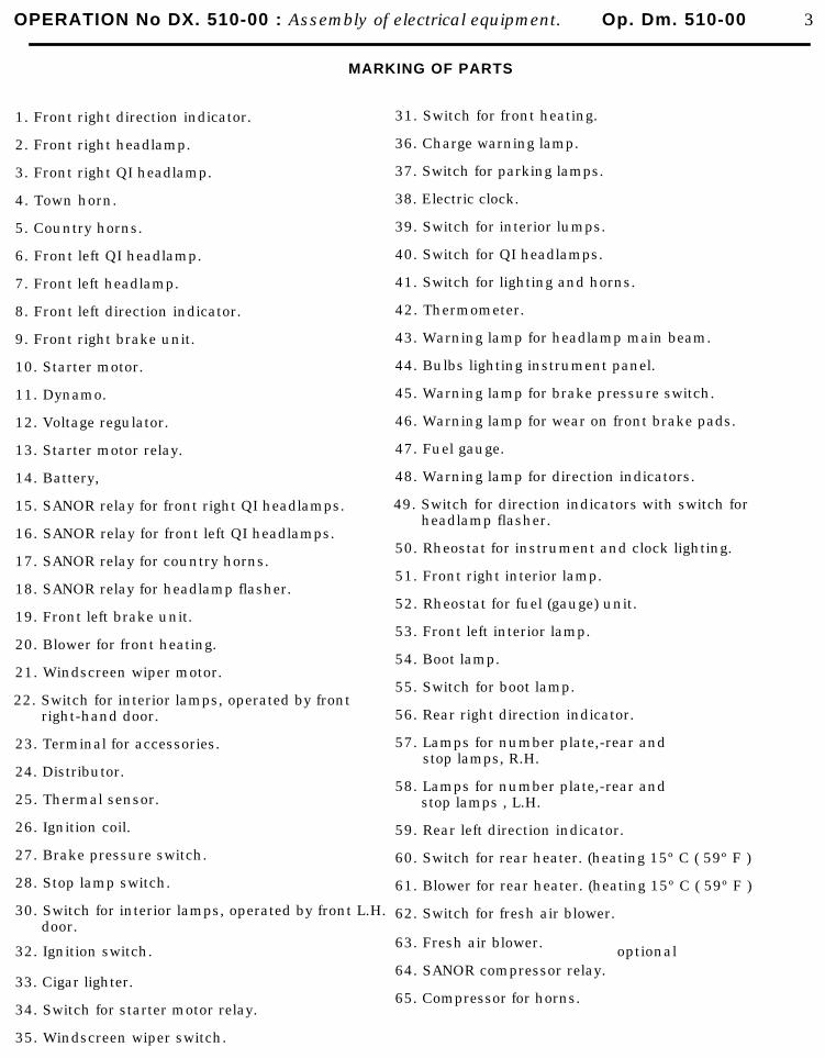
OPERATION No DX. 510-00 : Assembly of electrical equipment. Op. Dm. 510-00 3
MARKING OF PARTS
1. Front right direction indicator.
2. Front right headlamp.
3. Front right QI headlamp.
4. Town horn.
5. Country horns.
6. Front left QI headlamp.
7. Front left headlamp.
8. Front left direction indicator.
9. Front right brake unit.
10. Starter motor.
11. Dynamo.
12. Voltage regulator.
13. Starter motor relay.
14. Battery,
15. SANOR relay for front right QI headlamps.
16. SANOR relay for front left QI headlamps.
17. SANOR relay for country horns.
18. SANOR relay for headlamp flasher.
19. Front left brake unit.
20. Blower for front heating.
21. Windscreen wiper motor.
22. Switch for interior lamps, operated by frontright-hand door.
23. Terminal for accessories.
24. Distributor.
25. Thermal sensor.
26. Ignition coil.
27. Brake pressure switch.
28. Stop lamp switch.
30. Switch for interior lamps, operated by front L.H. door.
31. Switch for front heating.
36. Charge warning lamp.
37. Switch for parking lamps.
38. Electric clock.
39. Switch for interior lumps.
40. Switch for QI headlamps.
41. Switch for lighting and horns.
42. Thermometer.
43. Warning lamp for headlamp main beam.
44. Bulbs lighting instrument panel.
45. Warning lamp for brake pressure switch.
46. Warning lamp for wear on front brake pads.
47. Fuel gauge.
48. Warning lamp for direction indicators.
49. Switch for direction indicators with switch forheadlamp flasher.
50. Rheostat for instrument and clock lighting.
51. Front right interior lamp.
52. Rheostat for fuel (gauge) unit.
53. Front left interior lamp.
54. Boot lamp.
55. Switch for boot lamp.
56. Rear right direction indicator.
57. Lamps for number plate,-rear andstop lamps, R.H.
58. Lamps for number plate,-rear and stop lamps , L.H.
59. Rear left direction indicator.
60. Switch for rear heater. (heating 15º C ( 59º F )
61. Blower for rear heater. (heating 15º C ( 59º F )
62. Switch for fresh air blower.
32. Ignition switch.
33. Cigar lighter.
34. Switch for starter motor relay.
35. Windscreen wiper switch.
63. Fresh air blower.
64. SANOR compressor relay.
65. Compressor for horns.
optional
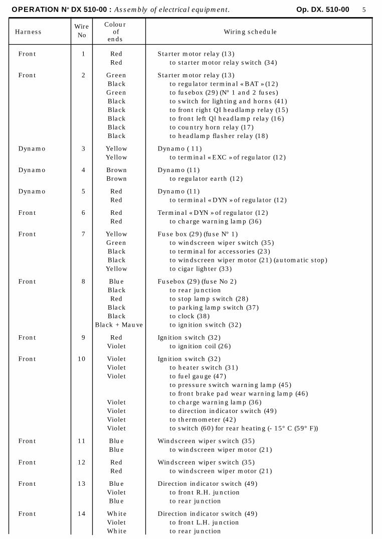
OPERATION No DX 510-00 : Assembly of electrical equipment. Op. DX. 510-00 5
HarnessWire No
Colourof
ends Wiring schedule
Front 1 Red Starter motor relay (13)Red to starter motor relay switch (34)
Front 2 Green Starter motor relay (13)Black to regulator terminal « BAT » (12)Green to fusebox (29) (Nº 1 and 2 fuses)Black to switch for lighting and horns (41)Black to front right QI headlamp relay (15)Black to front left Ql headlamp relay (16)Black to country horn relay (17)Black to headlamp flasher relay (18)
Dynamo 3 Yellow Dynamo ( 11)Yellow to terminal « EXC » of regulator (12)
Dynamo 4 Brown Dynamo (11)
Brown to regulator earth (12)
Dynamo 5 Red Dynamo (11)Red to terminal « DYN » of regulator (12)
Front 6 Red Terminal « DYN » of regulator (12)Red to charge warning lamp (36)
Front 7 Yellow Fuse box (29) (fuse Nº 1)Green to windscreen wiper switch (35)Black to terminal for accessories (23)Black to windscreen wiper motor (21) (automatic stop)Yellow to cigar lighter (33)
Front 8 Blue Fusebox (29) (fuse No 2)Black to rear junctionRed to stop lamp switch (28)
Black to parking lamp switch (37)Black to clock (38)
Black + Mauve to ignition switch (32)
Front 9 Red Ignition switch (32)Violet to ignition coil (26)
Front 10 Violet Ignition switch (32)Violet to heater switch (31)Violet to fuel gauge (47)
to pressure switch warning lamp (45)to front brake pad wear warning lamp (46)
Violet to charge warning lamp (36)Violet to direction indicator switch (49)Violet to thermometer (42)Violet to switch (60) for rear heating (- 15º C (59º F))
Front 11 Blue Windscreen wiper switch (35)Blue to windscreen wiper motor (21)
Front 12 Red Windscreen wiper switch (35)Red to windscreen wiper motor (21)
Front 13 Blue Direction indicator switch (49)Violet to front R.H. junctionBlue to rear junction
Front 14 White Direction indicator switch (49)Violet to front L.H. junctionWhite to rear junction
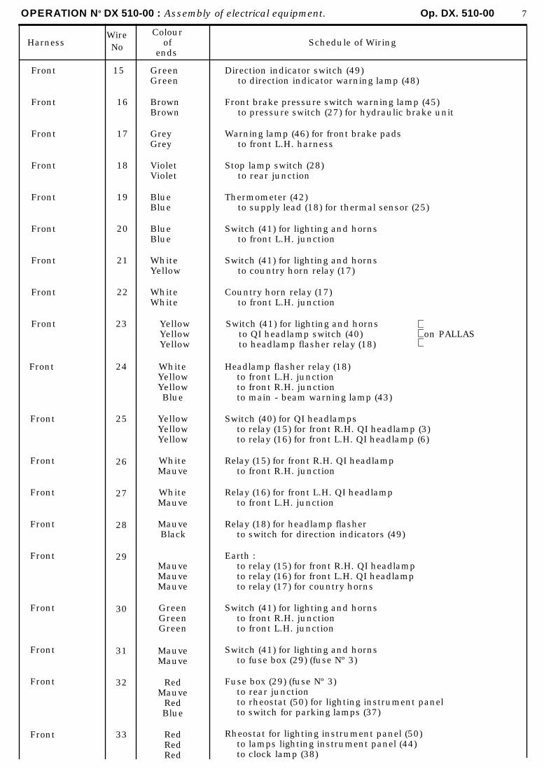
OPERATION No DX 510-00 : Assembly of electrical equipment. Op. DX. 510-00 7
HarnessWire No
Colourof
endsSchedule of Wiring
Front
Front
Front
Front
Front
Front
Front
Front
15
16
17
18
19
20
21
22
GreenGreen
BrownBrown
GreyGrey
VioletViolet
BlueBlue
BlueBlue
WhiteYellow
WhiteWhite
Direction indicator switch (49)to direction indicator warning lamp (48)
Front brake pressure switch warning lamp (45)to pressure switch (27) for hydraulic brake unit
Warning lamp (46) for front brake padsto front L.H. harness
Stop lamp switch (28)to rear junction
Thermometer (42)to supply lead (18) for thermal sensor (25)
Switch (41) for lighting and hornsto front L.H. junction
Switch (41) for lighting and hornsto country horn relay (17)
Country horn relay (17)to front L.H. junction
Front 23 YellowYellowYellow
Switch (41) for lighting and hornsto QI headlamp switch (40)to headlamp flasher relay (18)
on PALLAS
Front
Front
Front
Front
Front
Front
Front
Front
Front
Front
24
25
26
27
28
29
30
31
32
33
WhiteYellowYellowBlue
YellowYellowYellow
WhiteMauve
WhiteMauve
MauveBlack
MauveMauveMauve
GreenGreenGreen
MauveMauve
RedMauve
RedBlue
RedRedRed
Headlamp flasher relay (18)to front L.H. junctionto front R.H. junctionto main - beam warning lamp (43)
Switch (40) for QI headlampsto relay (15) for front R.H. QI headlamp (3)to relay (16) for front L.H. QI headlamp (6)
Relay (15) for front R.H. QI headlampto front R.H. junction
Relay (16) for front L.H. QI headlampto front L.H. junction
Relay (18) for headlamp flasherto switch for direction indicators (49)
Earth :to relay (15) for front R.H. QI headlampto relay (16) for front L.H. QI headlampto relay (17) for country horns
Switch (41) for lighting and hornsto front R.H. junctionto front L.H. junction
Switch (41) for lighting and hornsto fuse box (29) (fuse Nº 3)
Fuse box (29) (fuse Nº 3)to rear junctionto rheostat (50) for lighting instrument panelto switch for parking lamps (37)
Rheostat for lighting instrument panel (50)to lamps lighting instrument panel (44)to clock lamp (38)
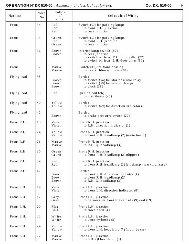
OPERATION No DX 510-00 : Assembly of electrical equipment. Op. DX. 510-00 9
HarnessWireNo
Colourof
endsSchedule of Wiring
Front
Front
Front
Front
Flying lead
Flying lead
Flying lead
Flying lead
Front R.H.
Front R.H.
Front R.H.
Front R.H.
Front R.H.
Front R.H.
Front L.H.
Front L.H.
Front L.H.
Front L.H.
Front L.H.
Front L.H.
34
35
36
37
38
39
40
42
13
24
26
30
34
42
14
17
20
22
24
27
RedRedRed
GreenRedGreen
BrownBrown
MauveMauve
BrownBrownBrown
Red
YellowYellow
Brown
VioletViolet
YellowYellow
MauveMauve
GreenGreen
RedRed
BrownBrownBrown
VioletViolet
GreyGrey
BlueBlue
WhiteWhite
YellowYellow
MauveMauve
Switch (37) for parking lampsto front R.H. junctionto rear junction
Switch (37) for parking lampsto front L.H. junctionto rear junction
Interior lamp switch (39)to rear junctionto switch on front R.H. door pillar (22)to switch on front L.H. door pillar (30)
Switch (31) for front heatingto heater blower motor (20)
Earth :to switch (34) for starter motor relayto switch (39) for interior lampsto clock (38)
Ignition coil (26)to distributor (25)
Earth :to switch (49) for direction indicators
Earth :to brake pressure switch (27)
Front R.H. junctionto R.H. direction indicator (1)
Front R.H. junctionto front R.H. headlamp (2) (main beam)
Front R.H. junctionto R.H. QI headlamp (3)
Front R.H. junctionto front R.H. headlamp (2) (dipped)
Front R.H. junctionto front R.H. headlamp (2) (sidelamp - parking lamp)
Earth :to front R.H. direction indicator (1)to front R.H. headlamp (2)to R.H. QI headlamp (3)
Front L.H. junctionto front L.H. direction indicator (8)
Front L.H. junctionto harness for front brake pads (9) and (19)
Front L.H. junctionto town horn (4)
Front L.H. junctionto country horns (5)
Front L.H. junctionto front L.H. headlamp (7) (main beam)
Front L.H. junctionto L.H. QI headlamp (6)
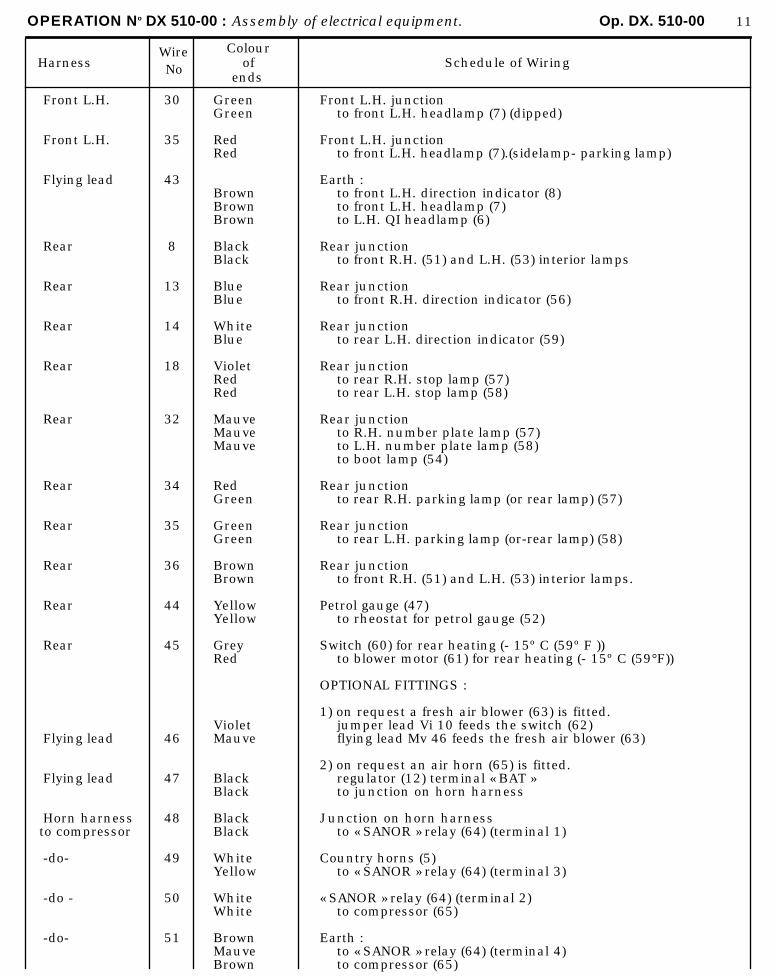
OPERATION No DX 510-00 : Assembly of electrical equipment. Op. DX. 510-00 11
HarnessWireNo
Colourof
endsSchedule of Wiring
Front L.H.
Front L.H.
Flying lead
Rear
Rear
Rear
Rear
Rear
Rear
Rear
Rear
Rear
Rear
Flying lead
Flying lead
Horn harness to compressor
-do-
-do -
-do-
30
35
43
8
13
14
18
32
34
35
36
44
45
46
47
48
49
50
51
GreenGreen
RedRed
BrownBrownBrown
BlackBlack
BlueBlue
WhiteBlue
VioletRedRed
MauveMauveMauve
RedGreen
GreenGreen
BrownBrown
YellowYellow
GreyRed
VioletMauve
BlackBlack
BlackBlack
WhiteYellow
WhiteWhite
BrownMauveBrown
Front L.H. junctionto front L.H. headlamp (7) (dipped)
Front L.H. junctionto front L.H. headlamp (7).(sidelamp- parking lamp)
Earth :to front L.H. direction indicator (8)to front L.H. headlamp (7)to L.H. QI headlamp (6)
Rear junctionto front R.H. (51) and L.H. (53) interior lamps
Rear junctionto front R.H. direction indicator (56)
Rear junctionto rear L.H. direction indicator (59)
Rear junctionto rear R.H. stop lamp (57)to rear L.H. stop lamp (58)
Rear junctionto R.H. number plate lamp (57)to L.H. number plate lamp (58)to boot lamp (54)
Rear junctionto rear R.H. parking lamp (or rear lamp) (57)
Rear junctionto rear L.H. parking lamp (or-rear lamp) (58)
Rear junctionto front R.H. (51) and L.H. (53) interior lamps.
Petrol gauge (47)to rheostat for petrol gauge (52)
Switch (60) for rear heating (- 15º C (59º F ))to blower motor (61) for rear heating (- 15º C (59°F))
OPTIONAL FITTINGS :
1) on request a fresh air blower (63) is fitted.jumper lead Vi 10 feeds the switch (62)flying lead Mv 46 feeds the fresh air blower (63)
2) on request an air horn (65) is fitted.regulator (12) terminal « BAT »to junction on horn harness
Junction on horn harnessto « SANOR » relay (64) (terminal 1)
Country horns (5)to « SANOR » relay (64) (terminal 3)
« SANOR » relay (64) (terminal 2)to compressor (65)
Earth :to « SANOR » relay (64) (terminal 4)to compressor (65)

OPERATION No DY. 510-00 : Arrangement of the electrical installation. Op. DY. 510-00 1
DY - DL - DE September 1965 September 1966
BULB TABLE
Description
Headlamp-main/dipped
Front flashersRear flashersStop lamp
Rear lampsNumber plate lampSpare bulbs
Front parking lamps
Front interior lamps on « PALLAS »
Quantity
2
6
6
2
2
Type of bulb
European P.45 E 41 (yellow selective) 12 v 45/40 w.
B.A. - 15 s - single contact 12 v - 15 w ( large bulb)On « Pallas » vehicles-single contact - 12v - 7w (large bulb)
B.A. - 15 s - single contact 12 v - 4 w Philips Hollande 12.821
B.A. 9 s - 12 v - 4 w tube diameter 10 mm
B.A. - 15 s - 12 v - 15 w ( large bulb )
FrontRear
Interior lamps 4 Festoon 12 v - 7 w
Dashboard lampBrake pressure warning lampBrake pad warning lamp
Charge warning lampClock lamp
Flasher warning lampHeadlamp warning lamp
Boot lamp
Optional Q.I. headlamp
4
2
2
1
2
B.A. - 9 s - 12 v - 2 w tube diameter 8,8 maxi (norma 1529)
B.A. - 9 s - 12 v - 1.5 w
B.A. 9 s -24v-3w
Festoon 12 v - 4 w
Q.I. bulb 12 v - 55 w (norma 112)
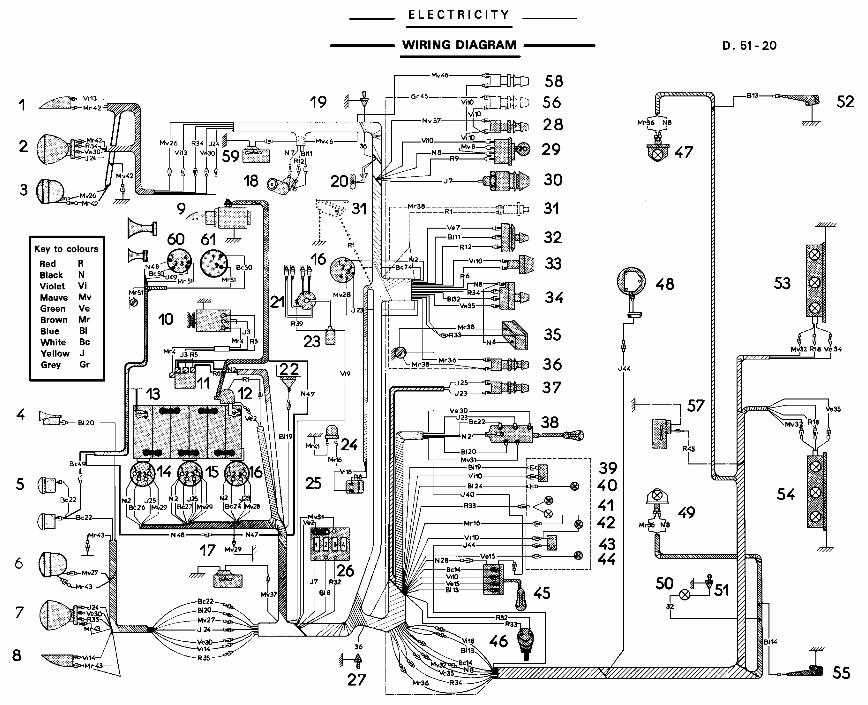
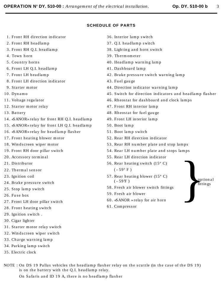
OPERATION N0 DY. 510-00 : Arrangement of the electrical installation. Op. DY. 510-00 b 3
SCHEDULE OF PARTS
1. Front RH direction indicator
2. Front RH headlamp
3. Front RH Q.I. headlamp
4. Town horn
5. Country horns
6. Front LH Q.I. headlamp
7. Front LH headlamp
8. Front LH direction indicator
9. Starter motor
10. Dynamo
11. Voltage regulator
12. Starter motor relay
13. Battery
14. «SANOR» relay for front RH Q.I. headlamp
15. «SANOR» relay for front LH Q.I. headlamp
16. «SANOR» relay for headlamp flasher
17. Front heating blower motor
18. Windscreen wiper motor
19. Front RH door pillar switch
20. Accessory terminal
36. Interior lamp switch
37. Q.I. headlamp switch
38. Lighting and horn switch
39. Thermometer
40. Headlamp warning lamp
41. Dashboard lamp
42. Brake pressure switch warning lamp
43. Fuel gauge
44. Direction indicator warning lamp
45. Switch for direction indicators and headlamp flasher
46. Rheostat for dashboard and clock lamps
47. Front RH interior lamp
48. Rheostat for fuel gauge
49. Front LH interior lamp
50. Boot lamp
51. Boot lamp switch
52. Rear RH direction indicator
53. Rear RH number plate and stop lamps
54. Rear LH number plate and stops lamps
55. Rear LH direction indicator
21. Distributor
22. Thermal sensor
23. Ignition coil
24. Brake pressure switch
25. Stop lamp switch
26. Fuse box
27. Front LH door pillar switch
28. Front heating switch
29. Ignition switch .
30. Cigar lighter
31. Starter motor relay switch
32. Windscreen wiper switch
33. Charge warning lamp
34. Parking lamp switch
35. Electric clock
56. Rear heating switch (15º C)
( - 59º F )
57. Rear heating blower (15º C) ( - 59’F )
58. Fresh air blower switch fittings
59. Fresh air blower
60. «SANOR » relay for air horn
61. Compressor
} optional fittings
NOTE : On DS 19 Pallas vehicles the headlamp flasher relay on the scuttle (in the case of the DS 19)is on the battery with the Q.I. headlamp relay.
On Safaris and ID 19 A, there is no headlamp flasher
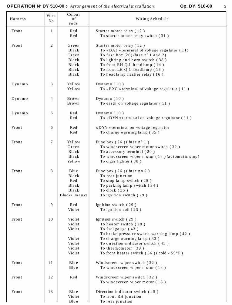
OPERATION No DY 510-00 : Arrangement of the electrical installation. Op. DY. 510-00 5
HarnessWireNo
Colourof
endsWiring Schedule
Front
Front
Dynamo
Dynamo
Dynamo
Front
Front
Front
Front
Front
Front
Front
Front
1
2
3
4
5
6
7
8
9
10
11
12
13
RedRed
GreenBlackGreenBlackBlackBlackBlack
YellowYellow
BrownBrown
RedRed
RedRed
YellowGreenBlackBlackYellow
BlueBlackRed
BlackBlack
Black/ mauve
RedViolet
VioletVioletViolet
VioletVioletVioletViolet
BlueBlue
Red
BlueVioletBlue
Starter motor relay ( 12 )To starter motor relay switch ( 31 )
Starter motor relay ( 12 )To « BAT » terminal of voltage regulator ( 11)To fuse box (26) (fuse no 1 and 2)To lighting and horn switch ( 38 )To front RH Q.I. headlamp ( 14 )To front LH Q.1 headlamp ( 15 )To headlamp flasher relay ( 16 )
Dynamo ( 10 )To « EXC » terminal of voltage regulator ( 11 )
Dynamo ( 10 )To earth on voltage regulator ( 11 )
Dynamo ( 10 )To « DYN » terminal on voltage regulator ( 11 )
« DYN » terminal on voltage regulatorTo charge warning lamp ( 35 )
Fuse box ( 26 ) ( fuse nº 1 )To windscreen wiper motor switch ( 32 )To accessory terminal ( 20 )To windscreen wiper motor ( 18 ) (automatic stop)To cigar lighter ( 30 )
Fuse box ( 26 ) ( fuse no 2 )To rear junctionTo stop lamp switch ( 25 )To parking lamp switch ( 34 )To clock ( 35 )To ignition switch ( 29 )
Ignition switch ( 29 )To ignition coil ( 23 )
Ignition switch ( 29 )To heater switch ( 28 )To fuel gauge ( 43 )To brake pressure switch warning lamp ( 42 )To charge warning lamp ( 33 )To direction indicator switch ( 45 )To thermometer ( 39 )To front heater switch ( 56 ) ( cold - 59°F )
Windscreen wiper switch ( 32 )To windscreen wiper motor ( 18 )
Windscreen wiper switch ( 32 )To windscreen wiper motor ( 18 )
Direction indicator switch ( 45 )To front RH junctionTo rear junction
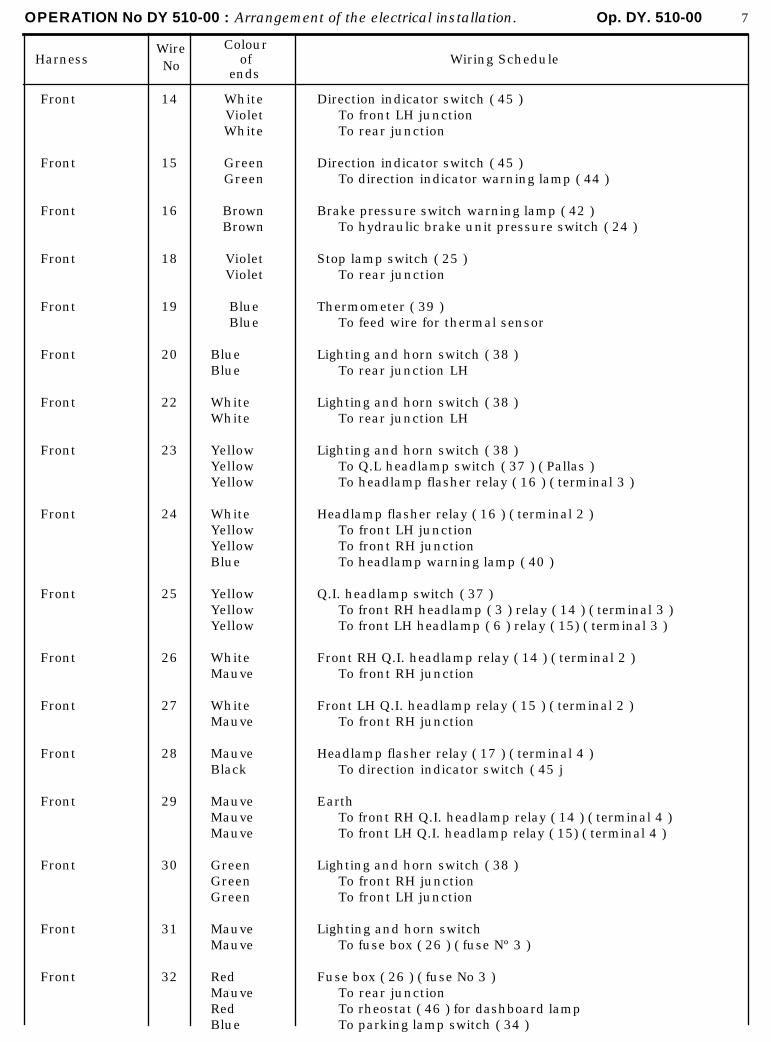
OPERATION No DY 510-00 : Arrangement of the electrical installation. Op. DY. 510-00 7
HarnessWireNo
Colourof
endsWiring Schedule
Front
Front
Front
Front
Front
Front
Front
Front
Front
Front
Front
Front
Front
Front
Front
Front
Front
14
15
16
18
19
20
22
23
24
25
26
27
28
29
30
31
32
WhiteVioletWhite
GreenGreen
BrownBrown
VioletViolet
BlueBlue
BlueBlue
WhiteWhite
YellowYellowYellow
WhiteYellowYellowBlue
YellowYellowYellow
WhiteMauve
WhiteMauve
MauveBlack
MauveMauveMauve
GreenGreenGreen
MauveMauve
RedMauveRedBlue
Direction indicator switch ( 45 )To front LH junctionTo rear junction
Direction indicator switch ( 45 )To direction indicator warning lamp ( 44 )
Brake pressure switch warning lamp ( 42 )To hydraulic brake unit pressure switch ( 24 )
Stop lamp switch ( 25 )To rear junction
Thermometer ( 39 )To feed wire for thermal sensor
Lighting and horn switch ( 38 )To rear junction LH
Lighting and horn switch ( 38 )To rear junction LH
Lighting and horn switch ( 38 )To Q.L headlamp switch ( 37 ) ( Pallas )To headlamp flasher relay ( 16 ) ( terminal 3 )
Headlamp flasher relay ( 16 ) ( terminal 2 )To front LH junctionTo front RH junctionTo headlamp warning lamp ( 40 )
Q.I. headlamp switch ( 37 )To front RH headlamp ( 3 ) relay ( 14 ) ( terminal 3 )To front LH headlamp ( 6 ) relay ( 15) ( terminal 3 )
Front RH Q.I. headlamp relay ( 14 ) ( terminal 2 )To front RH junction
Front LH Q.I. headlamp relay ( 15 ) ( terminal 2 )To front RH junction
Headlamp flasher relay ( 17 ) ( terminal 4 )To direction indicator switch ( 45 j
EarthTo front RH Q.I. headlamp relay ( 14 ) ( terminal 4 )To front LH Q.I. headlamp relay ( 15) ( terminal 4 )
Lighting and horn switch ( 38 )To front RH junctionTo front LH junction
Lighting and horn switchTo fuse box ( 26 ) ( fuse Nº 3 )
Fuse box ( 26 ) ( fuse No 3 )To rear junctionTo rheostat ( 46 ) for dashboard lampTo parking lamp switch ( 34 )

OPERATION No DY 510-00 : Arrangement of the electrical installation. Op. DY. 510-00 9
HarnessWireNo
Colourof
endsWiring Schedule
Front
Front
Front
Front
Front
Flying lead
Flying lead
Flying lead
Flying lead
Front RH
Front RH
Front RH
Front RH
Front RH
Front RH
Front LH
33
34
35
36
37
38
39
40
41
13
24
26
30
34
42
14
RedRedRed
RedRedRed
GreenRedGreen
BrownBrown
MauveMauve
BrownBrownBrown
RedRed
YellowYellow
Brown
VioletViolet
YellowYellow
MauveMauve
GreenGreen
RedRed
BrownBrownBrown
VioletViolet
Rheostat ( 46 ) for dashboard lampTo dashboard lamp ( 41 )To clock lamp ( 35 )
Parking lamp switch ( 34 )To front RH junctionTo rear junction
Parking lamp switch ( 34 )To front LH junctionTo rear junction
Interior lamp switch ( 36 )To rear junctionTo RH door pillar switch ( 19 )To LH door pillar switch ( 27 )
Front heating switch ( 28 )To heating unit motor ( 17 )
EarthTo starter motor relay switch ( 31 )To interior lamp switch ( 36 )To clock ( 35 )
Ignition coil ( 23 )To distributor ( 21 )
EarthTo direction indicator switch ( 45 )
EarthTo brake pressure switch ( 24 )
Front RH junctionTo RH direction indicator ( 1 )
Front RH junctionTo front RH headlamp ( 2 ) main beam
Front RH junctionTo front Q.I. headlamp ( 3 )
Front RH junctionTo front RH headlamp ( 2 ) dipped beam
Front RH junctionTo front RH headlamp ( sidelamp - parking lamp ) ( 2 )
EarthTo front RH direction indicator ( 1 )To front RH headlamp ( 2 )To RH Q.I. headlamp ( 3 )
Front LH junctionTo front LH direction indicator ( 8 )
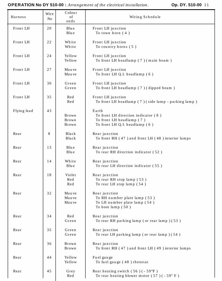
OPERATION No DY 510-00 : Arrangement of the electrical installation. Op. DY. 510-00 11
HarnessWireNo
Colourof
endsWiring Schedule
Front LH
Front LH
Front LH
Front LH
Front LH
Front LH
Flying lead
Rear
Rear
Rear
Rear
Rear
Rear
Rear
Rear
Rear
Rear
20
22
24
27
30
35
43
8
13
14
18
32
34
35
36
44
45
BlueBlue
WhiteWhite
YellowYellow
MauveMauve
GreenGreen
RedRed
BrownBrownBrown
BlackBlack
BlueBlue
WhiteBlue
VioletRedRed
MauveMauveMauve
RedGreen
GreenGreen
BrownBrown
YellowYellow
GreyRed
Front LH junctionTo town horn ( 4 )
Front LH junctionTo country horns ( 5 )
Front LH junctionTo front LH headlamp ( 7 ) ( main beam )
Front LH junctionTo front LH Q.I. headlamp ( 6 )
Front LH junctionTo front LH headlamp ( 7 ) ( dipped beam )
Front LH junctionTo front LH headlamp ( 7 ) ( side lamp - parking lamp )
EarthTo front LH direction indicator ( 8 )To front LH headlamp ( 7 )To front LH Q.I. headlamp ( 6 )
Rear junctionTo front RH ( 47 ) and front LH ( 48 ) interior lamps
Rear junctionTo rear RH direction indicator ( 52 )
Rear junctionTo rear LH direction indicator ( 55 )
Rear junctionTo rear RH stop lamp ( 53 )To rear LH stop lamp ( 54 )
Rear junctionTo RH number plate lamp ( 53 )To LH number plate lamp ( 54 )To boot lamp ( 50 )
Rear junctionTo rear RH parking lamp ( or rear lamp ) ( 53 )
Rear junctionTo rear LH parking lamp ( or rear lamp ) ( 54 )
Rear junctionTo front RH ( 47 ) and front LH ( 49 ) interior lamps
Fuel gaugeTo fuel gauge ( 48 ) rheostat
Rear heating switch ( 56 ) ( - 59°F )To rear heating blower motor ( 57 ) ( - 59º F )
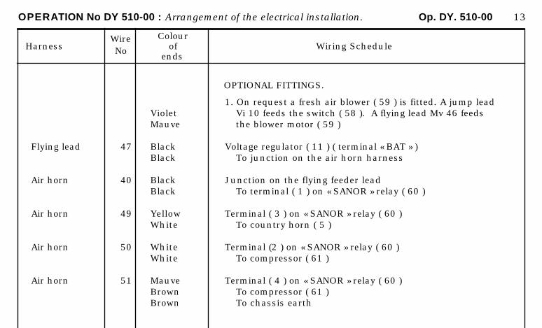
OPERATION No DY 510-00 : Arrangement of the electrical installation. Op. DY. 510-00 13
HarnessWireNo
Colourof
endsWiring Schedule
Flying lead
Air horn
Air horn
Air horn
Air horn
47
40
49
50
51
VioletMauve
BlackBlack
BlackBlack
YellowWhite
WhiteWhite
MauveBrownBrown
OPTIONAL FITTINGS.
1. On request a fresh air blower ( 59 ) is fitted. A jump leadVi 10 feeds the switch ( 58 ). A flying lead Mv 46 feedsthe blower motor ( 59 )
Voltage regulator ( 11 ) ( terminal « BAT » )To junction on the air horn harness
Junction on the flying feeder leadTo terminal ( 1 ) on « SANOR » relay ( 60 )
Terminal ( 3 ) on « SANOR » relay ( 60 )To country horn ( 5 )
Terminal (2 ) on « SANOR » relay ( 60 )To compressor ( 61 )
Terminal ( 4 ) on « SANOR » relay ( 60 )To compressor ( 61 )To chassis earth
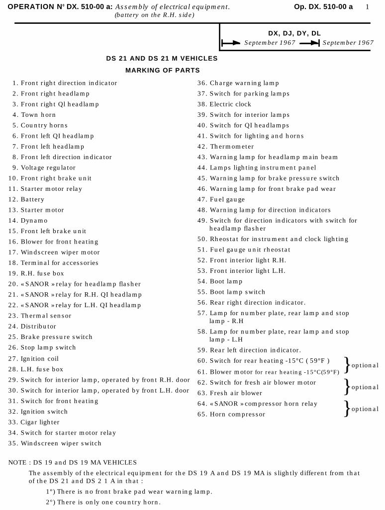
OPERATION N0 DX. 510-00 a: Assembly of electrical equipment. Op. DX. 510-00 a 1(battery on the R.H. side)
DX, DJ, DY, DL September 1967 September 1967
DS 21 AND DS 21 M VEHICLES
MARKING OF PARTS
1. Front right direction indicator
2. Front right headlamp
3. Front right Ql headlamp
4. Town horn
5. Country horns
6. Front left QI headlamp
7. Front left headlamp
8. Front left direction indicator
9. Voltage regulator
10. Front right brake unit
11. Starter motor relay
12. Battery
13. Starter motor
14. Dynamo
15. Front left brake unit
16. Blower for front heating
17. Windscreen wiper motor
18. Terminal for accessories
19. R.H. fuse box
20. « SANOR » relay for headlamp flasher
21. « SANOR » relay for R.H. QI headlamp
22. « SANOR » relay for L.H. QI headlamp
23. Thermal sensor
24. Distributor
25. Brake pressure switch
26. Stop lamp switch
36. Charge warning lamp
37. Switch for parking lamps
38. Electric clock
39. Switch for interior lamps
40. Switch for QI headlamps
41. Switch for lighting and horns
42. Thermometer
43. Warning lamp for headlamp main beam
44. Lamps lighting instrument panel
45. Warning lamp for brake pressure switch
46. Warning lamp for front brake pad wear
47. Fuel gauge
48. Warning lamp for direction indicators
49. Switch for direction indicators with switch for headlamp flasher
50. Rheostat for instrument and clock lighting
51. Fuel gauge unit rheostat
52. Front interior light R.H.
53. Front interior light L.H.
54. Boot lamp
55. Boot lamp switch
56. Rear right direction indicator.
57. Lamp for number plate, rear lamp and stoplamp - R.H
58. Lamp for number plate, rear lamp and stoplamp - L.H
59. Rear left direction indicator.27. Ignition coil
28. L.H. fuse box
29. Switch for interior lamp, operated by front R.H. door
30. Switch for interior lamp, operated by front L.H. door
31. Switch for front heating
32. Ignition switch
33. Cigar lighter
34. Switch for starter motor relay
35. Windscreen wiper switch
60. Switch for rear heating -15ºC ( 59ºF )
61. Blower motor for rear heating -15ºC(59ºF)
62. Switch for fresh air blower motor
63. Fresh air blower
64. « SANOR » compressor horn relay
65. Horn compressor
}}}
optional
optional
optional
NOTE : DS 19 and DS 19 MA VEHICLES
The assembly of the electrical equipment for the DS 19 A and DS 19 MA is slightly different from thatof the DS 21 and DS 2 1 A in that :
1º) There is no front brake pad wear warning lamp.
2º) There is only one country horn.
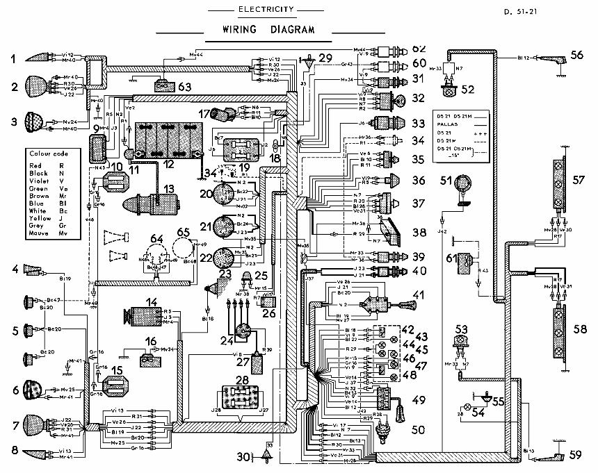
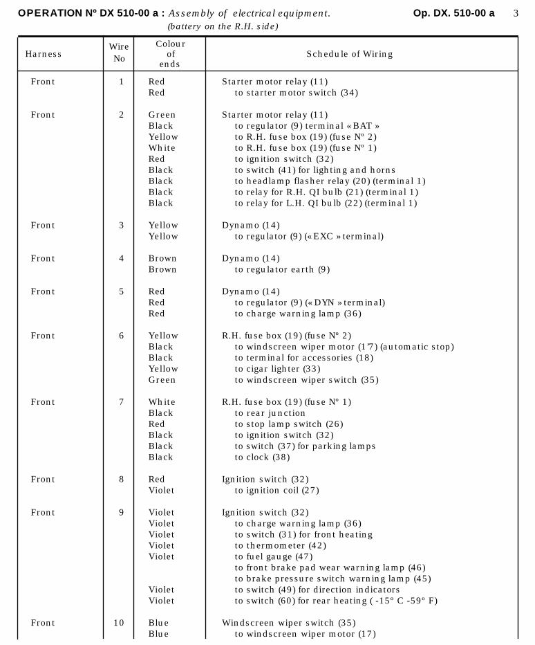
OPERATION Nº DX 510-00 a : Assembly of electrical equipment. Op. DX. 510-00 a 3(battery on the R.H. side)
HarnessWireNo
Colourof
endsSchedule of Wiring
Front
Front
Front
Front
Front
Front
Front
Front
Front
Front
1
2
3
4
5
6
7
8
9
10
RedRed
GreenBlackYellowWhiteRedBlackBlackBlackBlack
YellowYellow
BrownBrown
RedRedRed
YellowBlackBlackYellowGreen
WhiteBlackRedBlackBlackBlack
RedViolet
VioletVioletVioletVioletViolet
VioletViolet
BlueBlue
Starter motor relay (11)to starter motor switch (34)
Starter motor relay (11)to regulator (9) terminal « BAT »to R.H. fuse box (19) (fuse Nº 2)to R.H. fuse box (19) (fuse Nº 1)to ignition switch (32)to switch (41) for lighting and hornsto headlamp flasher relay (20) (terminal 1)to relay for R.H. QI bulb (21) (terminal 1)to relay for L.H. QI bulb (22) (terminal 1)
Dynamo (14)to regulator (9) (« EXC » terminal)
Dynamo (14)to regulator earth (9)
Dynamo (14)to regulator (9) (« DYN » terminal)to charge warning lamp (36)
R.H. fuse box (19) (fuse Nº 2)to windscreen wiper motor (1’7) (automatic stop)to terminal for accessories (18)to cigar lighter (33)to windscreen wiper switch (35)
R.H. fuse box (19) (fuse Nº 1)to rear junctionto stop lamp switch (26)to ignition switch (32)to switch (37) for parking lampsto clock (38)
Ignition switch (32)to ignition coil (27)
Ignition switch (32)to charge warning lamp (36)to switch (31) for front heatingto thermometer (42)to fuel gauge (47)to front brake pad wear warning lamp (46)to brake pressure switch warning lamp (45)to switch (49) for direction indicatorsto switch (60) for rear heating ( -15º C -59º F)
Windscreen wiper switch (35)to windscreen wiper motor (17)
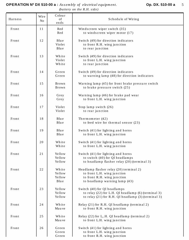
OPERATION Nº DX 510-00 a : Assembly of electrical equipment. Op. DX. 510-00 a 5(battery on the R.H. side)
HarnessWireNo
Colourof
endsSchedule of Wiring
Front
Front
Front
Front
Front
Front
Front
Front
Front
Front
Front
Front
Front
Front
Front
Front
11
12
13
14
15
16
17
18
19
20
21
22
23
24
25
26
RedRed
BlueVioletBlue
WhiteVioletWhite
GreenGreen
BrownBrown
GreyGrey
VioletViolet
BlueBlue
BlueBlue
WhiteWhite
YellowYellowYellow
WhiteYellowYellowBlue
YellowYellowYellow
WhiteMauve
WhiteMauve
GreenGreenGreen
Windscreen wiper switch (35)to windscreen wiper motor (17)
Switch (49) for direction indicatorsto front R.H. wing junctionto rear junction
Switch (49) for direction indicatorsto front L.H. wing junctionto rear junction
Switch (49) for direction indicatorsto warning lamp (48) for direction indicators
Warning lamp (45) for front brake pressure switchto brake pressure switch (25)
Warning lamp (46) for brake pad wearto front L.H. wing junction
Stop lamp switch (26)to rear junction
Thermometer (42)to feed wire for thermal sensor (23)
Switch (41) for lighting and hornsto front L.H. wing junction
Switch (41) for lighting and hornsto front L.H. wing junction
Switch (41) for lighting and hornsto switch (40) for QI headlampsto headlamp flasher relay (20) (terminal 3)
Headlamp flasher relay (20) terminal 2)to front L.H. wing junctionto front R.H. wing junctionto headlamp warning lamp (43)
Switch (40) for QI headlampsto relay (22) for L.H. QI headlamp (6) (terminal 3)to relay (21) for R.H. QI headlamp (3) (terminal 3)
Relay (21) for R.H. QI headlamp (terminal 2)to front R.H. wing junction
Relay (22) for L,.H. QI headlamp (terminal 2)to front L.H. wing junction
Switch (41) for lighting and hornsto front L.H. wing junctionto front R.H. wing junction

OPERATION Nº DX 510-00 a : Assembly of electrical equipment. Op. DX. 510-00 a 7(battery on the R.H. side)
HarnessWireNo
Colourof
endsSchedule of Wiring
Front
Front
Front
Front
Front
Front
Front
Front
Flying lead
Flying lead
Flying lead
Flying lead
Flying lead.
Front R.H.
Front R.H
27
28
29
30
31
32
33
34
35
36
37
38
39
12
22
MauveYellow
YellowMauveRedBlue
RedRedRed
RedRedRed
GreenRedGreen
MauveBlack
BrownBrown
MauveMauve
MauveMauveMauve
BrownBrownBrownBrown
YellowYellow
Brown
Red
VioletViolet
YellowYellow
Switch (41) for lighting and hornsto L.H. fuse box 28 (fuse Nº 1)
L.H. fuse box (28) (fuse Nº 1)to rear junctionto rheostat (50) for lighting instrument panel and clockto parking lamp switch (37)
Rheostat (50).for lighting instrument panel and clockto lamps lighting instrument panel (44)to clock lamp (38)
Switch for parking lamps (37)to R.H. wing junctionto rear junction
Parking lamp switch (37)to L.H. wing junctionto rear junction
Head lamp flasher relay (20) (terminal 4)to switch (49) for direction indicators
Switch for interior lamp (39)to rear junctionto switch for interior lamp operated by front L.H. door (30)to switch for interior lamp operated by front R.H. door (29)
Switch for front heating (31)to blower motor (16)
Earthto relay (21) for R.H. QI headlamp (terminal 4)to relay (22) for L.H. QI headlamp (terminal 4)
Earthto switch (34) for starter relayto switch (39) for interior lampsto clock (38)
Earthto switch for direction indicators (49)
Earthto brake pressure switch (25)
Ignition coil (27)to distributor (24)
Front junction R.H.to R.H. direction indicator (1)
Front junction R.H.to front R.H. headlamp (2) (main beam)
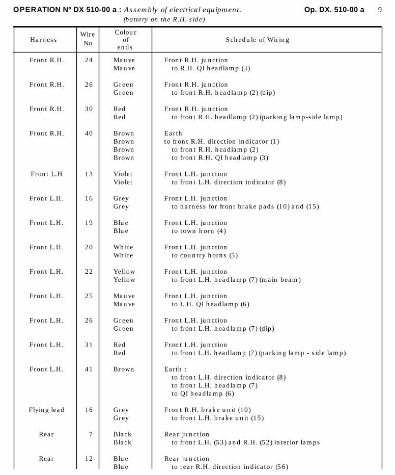
OPERATION Nº DX 510-00 a : Assembly of electrical equipment. Op. DX. 510-00 a 9(battery on the R.H. side)
HarnessWireNo
Colourof
endsSchedule of Wiring
Front R.H.
Front R.H.
Front R.H.
Front R.H.
Front L.H
Front L.H.
Front L.H.
Front L.H.
Front L.H.
Front L.H.
Front L.H.
Front L.H.
Front L.H.
Flying lead
Rear
Rear
24
26
30
40
13
16
19
20
22
25
26
31
41
16
7
12
MauveMauve
GreenGreen
RedRed
BrownBrownBrownBrown
VioletViolet
GreyGrey
BlueBlue
WhiteWhite
YellowYellow
MauveMauve
GreenGreen
RedRed
Brown
GreyGrey
BlackBlack
BlueBlue
Front R.H. junctionto R.H. QI headlamp (3)
Front R.H. junctionto front R.H. headlamp (2) (dip)
Front R.H. junctionto front R.H. headlamp (2) (parking lamp-side lamp)
Earthto front R.H. direction indicator (1)
to front R.H. headlamp (2)to front R.H. QI headlamp (3)
Front L.H. junctionto front L.H. direction indicator (8)
Front L.H. junctionto harness for front brake pads (10) and (15)
Front L.H. junctionto town horn (4)
Front L.H. junctionto country horns (5)
Front L.H. junctionto front L.H. headlamp (7) (main beam)
Front L.H. junctionto L.H. QI headlamp (6)
Front L.H. junctionto front L.H. headlamp (7) (dip)
Front L.H. junctionto front L.H. headlamp (7) (parking lamp - side lamp)
Earth :to front L.H. direction indicator (8)to front L.H. headlamp (7)to QI headlamp (6)
Front R.H. brake unit (10)to front L.H. brake unit (15)
Rear junctionto front L.H. (53) and R.H. (52) interior lamps
Rear junctionto rear R.H. direction indicator (56)
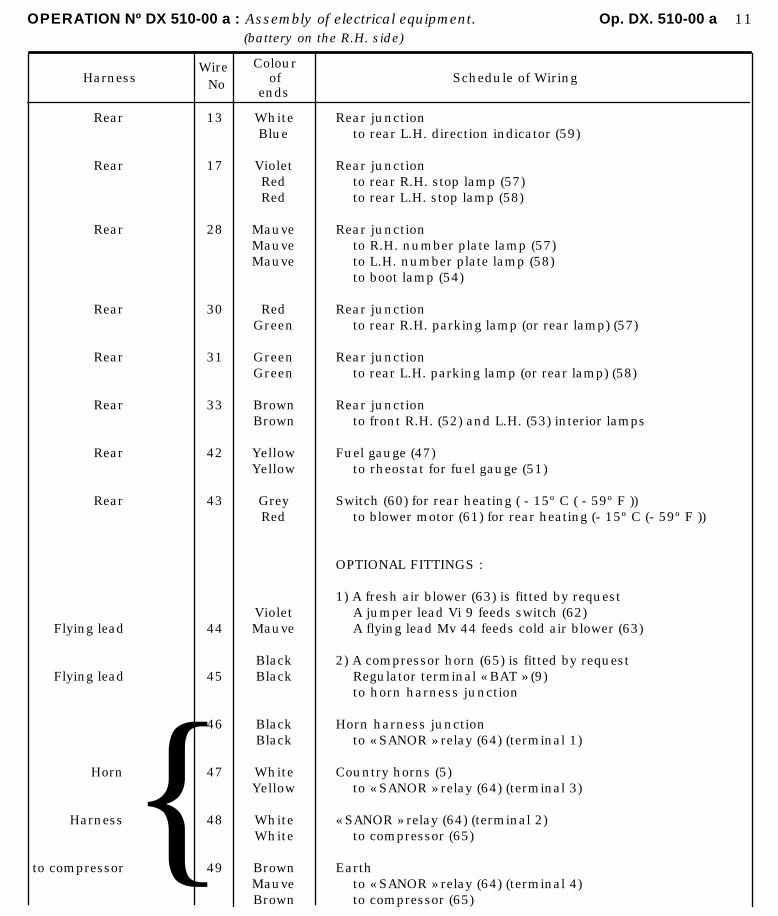
OPERATION Nº DX 510-00 a : Assembly of electrical equipment. Op. DX. 510-00 a 11(battery on the R.H. side)
HarnessWire
No
Colourof
endsSchedule of Wiring
Rear
Rear
Rear
Rear
Rear
Rear
Rear
Rear
Flying lead
Flying lead
Horn
Harness
to compressor{
13
17
28
30
31
33
42
43
44
45
46
47
48
49
WhiteBlue
VioletRedRed
MauveMauveMauve
RedGreen
GreenGreen
BrownBrown
YellowYellow
GreyRed
VioletMauve
BlackBlack
BlackBlack
WhiteYellow
WhiteWhite
BrownMauveBrown
Rear junctionto rear L.H. direction indicator (59)
Rear junctionto rear R.H. stop lamp (57)to rear L.H. stop lamp (58)
Rear junctionto R.H. number plate lamp (57)to L.H. number plate lamp (58)to boot lamp (54)
Rear junctionto rear R.H. parking lamp (or rear lamp) (57)
Rear junctionto rear L.H. parking lamp (or rear lamp) (58)
Rear junctionto front R.H. (52) and L.H. (53) interior lamps
Fuel gauge (47)to rheostat for fuel gauge (51)
Switch (60) for rear heating ( - 15º C ( - 59º F ))to blower motor (61) for rear heating (- 15º C (- 59º F ))
OPTIONAL FITTINGS :
1) A fresh air blower (63) is fitted by requestA jumper lead Vi 9 feeds switch (62)A flying lead Mv 44 feeds cold air blower (63)
2) A compressor horn (65) is fitted by requestRegulator terminal « BAT » (9)to horn harness junction
Horn harness junctionto « SANOR » relay (64) (terminal 1)
Country horns (5)to « SANOR » relay (64) (terminal 3)
« SANOR » relay (64) (terminal 2)to compressor (65)
Earthto « SANOR » relay (64) (terminal 4)to compressor (65)
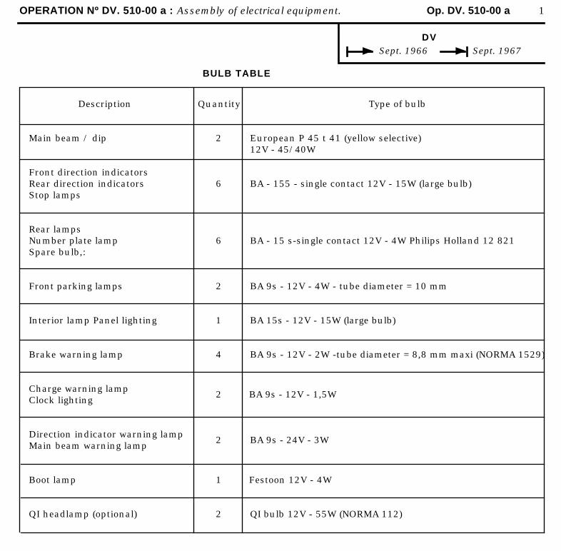
OPERATION Nº DV. 510-00 a : Assembly of electrical equipment. Op. DV. 510-00 a 1
DV Sept. 1966 Sept. 1967
BULB TABLE
Description
Main beam / dip
Front direction indicatorsRear direction indicatorsStop lamps
Rear lampsNumber plate lampSpare bulb,:
Front parking lamps
Interior lamp Panel lighting
Brake warning lamp
Charge warning lampClock lighting
Direction indicator warning lampMain beam warning lamp
Boot lamp
QI headlamp (optional)
Quantity
2
6
6
2
1
4
2
2
1
2
Type of bulb
European P 45 t 41 (yellow selective)12V - 45/40W
BA - 155 - single contact 12V - 15W (large bulb)
BA - 15 s-single contact 12V - 4W Philips Holland 12 821
BA 9s - 12V - 4W - tube diameter = 10 mm
BA 15s - 12V - 15W (large bulb)
BA 9s - 12V - 2W -tube diameter = 8,8 mm maxi (NORMA 1529)
BA 9s - 12V - 1,5W
BA 9s - 24V - 3W
Festoon 12V - 4W
QI bulb 12V - 55W (NORMA 112)
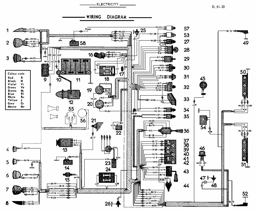
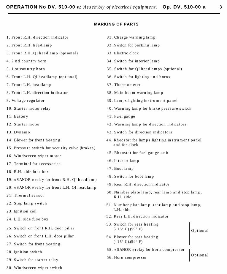
OPERATION No DV. 510-00 a: Assembly of electrical equipment. Op. DV. 510-00 a 3
MARKING OF PARTS
1. Front R.H. direction indicator
2. Front R.H. headlamp
3. Front R.H. QI headlamp (optional)
4. 2 nd country horn
5. 1 st country horn
6. Front L.H. QI headlamp (optional)
7. Front L.H. headlamp
8. Front L.H. direction indicator
9. Voltage regulator
10. Starter motor relay
11. Battery
12. Starter motor
13. Dynamo
14. Blower for front heating
15. Pressure switch for security valve (brakes)
16. Windscreen wiper motor
17. Terminal for accessories
18. R.H. side fuse box
19. « SANOR » relay for front R.H. QI headlamp
20. « SANOR » relay for front L.H. QI headlamp
21. Thermal sensor
22. Stop lamp switch
23. Ignition coil
31. Charge warning lamp
32. Switch for parking lamp
33. Electric clock
34. Switch for interior lamp
35. Switch for QI headlamps (optional)
36. Switch for lighting and horns
37. Thermometer
38. Main beam warning lamp
39. Lamps lighting instrument panel
40. Warning lamp for brake pressure switch
41. Fuel gauge
42. Warning lamp for direction indicators
43. Switch for direction indicators
44. Rheostat for lamps lighting instrument paneland for clock
45. Rheostat for fuel gauge unit
46. Interior lamp
47. Boot lamp
48. Switch for boot lamp
49. Rear R.H. direction indicator
50. Number plate lamp, rear lamp and stop lamp,R.H. side
51. Number plate lamp. rear lamp and stop lamp,L.H. side
24. L.H. side fuse box
25. Switch on front R.H. door pillar
26. Switch on front L.H. door pillar
27. Switch for front heating
28. Ignition switch
29. Switch for starter relay
30. Windscreen wiper switch
52. Rear L.H. direction indicator
53. Switch for rear heating(- 15º C) (59º F)
54. Blower for rear heating(- 15º C),(59º F)
55. « SANOR » relay for horn compressor
56. Horn compressor
Optional
Optional
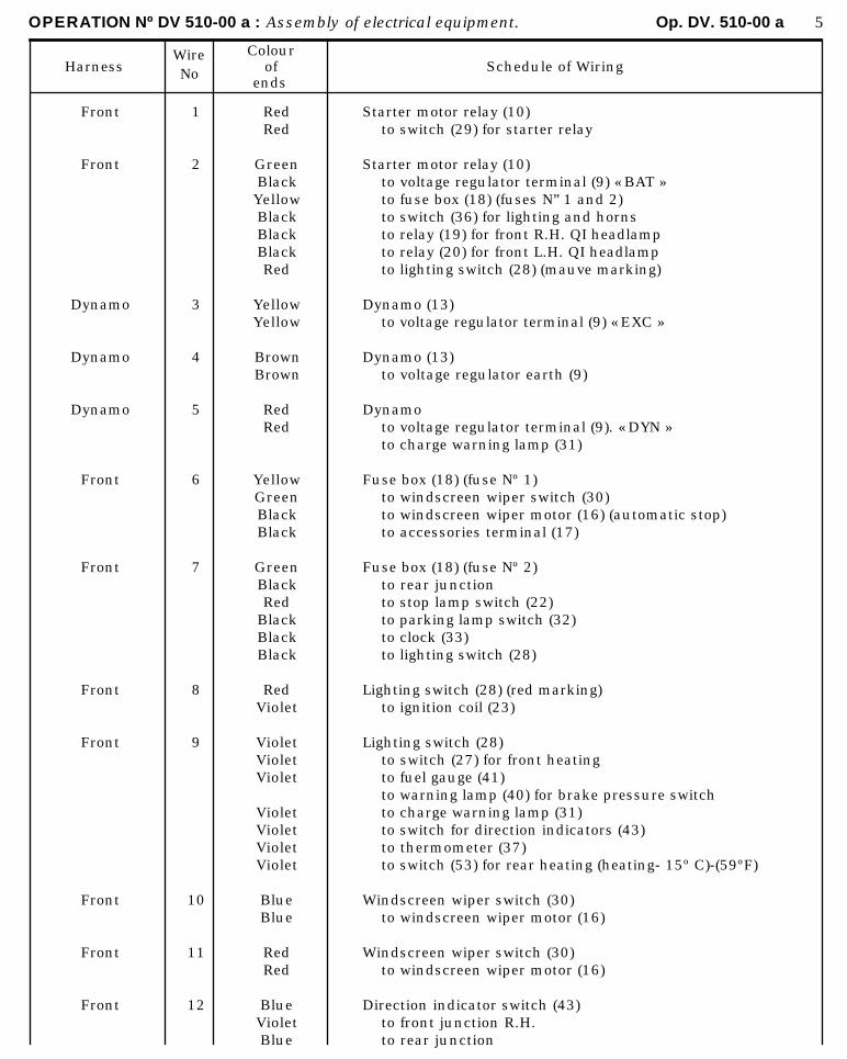
OPERATION Nº DV 510-00 a : Assembly of electrical equipment. Op. DV. 510-00 a 5
HarnessWireNo
Colourof
endsSchedule of Wiring
Front
Front
Dynamo
Dynamo
Dynamo
Front
Front
Front
Front
Front
Front
Front
1
2
3
4
5
6
7
8
9
10
11
12
RedRed
GreenBlackYellowBlackBlackBlackRed
YellowYellow
BrownBrown
RedRed
YellowGreenBlackBlack
GreenBlackRed
BlackBlackBlack
RedViolet
VioletVioletViolet
VioletVioletVioletViolet
BlueBlue
RedRed
BlueVioletBlue
Starter motor relay (10)to switch (29) for starter relay
Starter motor relay (10)to voltage regulator terminal (9) « BAT »to fuse box (18) (fuses N” 1 and 2)to switch (36) for lighting and hornsto relay (19) for front R.H. QI headlampto relay (20) for front L.H. QI headlampto lighting switch (28) (mauve marking)
Dynamo (13)to voltage regulator terminal (9) « EXC »
Dynamo (13)to voltage regulator earth (9)
Dynamoto voltage regulator terminal (9). « DYN »to charge warning lamp (31)
Fuse box (18) (fuse Nº 1)to windscreen wiper switch (30)to windscreen wiper motor (16) (automatic stop)to accessories terminal (17)
Fuse box (18) (fuse Nº 2)to rear junctionto stop lamp switch (22)to parking lamp switch (32)to clock (33)to lighting switch (28)
Lighting switch (28) (red marking)to ignition coil (23)
Lighting switch (28)to switch (27) for front heatingto fuel gauge (41)to warning lamp (40) for brake pressure switchto charge warning lamp (31)to switch for direction indicators (43)to thermometer (37)to switch (53) for rear heating (heating- 15º C)-(59ºF)
Windscreen wiper switch (30)to windscreen wiper motor (16)
Windscreen wiper switch (30)to windscreen wiper motor (16)
Direction indicator switch (43)to front junction R.H.to rear junction
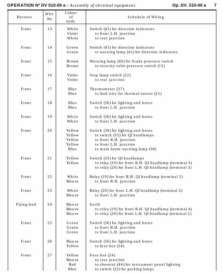
OPERATION Nº DV 510-00 a : Assembly of electrical equipment. Op. DV. 510-00 a 7
HarnessWireNo
Colourof
endsSchedule of Wiring
Front
Front
Front
Front
Front
Front
Front
Front
Front
Front
Front
Flying lead
Front
Front
Front
13
14
15
16
17
18
19
20
21
22
23
24
25
26
27
WhiteVioletWhite
GreenGreen
BrownBrown
VioletViolet
BlueBlue
BlueBlue
WhiteWhite
YellowYellowYellowYellowBlue
YellowYellow
WhiteMauve
WhiteMauve
MauveMauveMauve
GreenGreenGreen
MauveYellow
YellowMauve
RedBlue
Switch (43) for direction indicatorsto front L.H. junctionto rear junction
Switch (43) for direction indicatorsto warning lamp (42) for direction indicators
Warning lamp (40) for brake pressure switchto security valve pressure switch (15)
Stop lamp switch (22)to rear junction
Thermometer (37)to feed wire for thermal sensor (21)
Switch (36) for lighting and hornsto front L.H. junction
Switch (36) for lighting and hornsto front L.H. junction
Switch (36) for lighting and hornsto switch (35) for QI headlampsto front R.H. junctionto front L.H. junctionto main beam warning lamp (38)
Switch (35) for QI headlampsto relay (19) for front R.H. QI headlamp (terminal 3)to relay (20) for front L.H. QI headlamp (terminal 3)
Relay (19) for front R.H. QI headlamp (terminal 2)to front R.H. junction
Relay (20) for front L.H. QI headlamp (terminal 2)to front L.H. junction
Earthto relay (19) for front R.H. QI headlamp (terminal 4)to relay (20) for front L.H. QI headlamp (terminal 2)
Switch (36) for lighting and hornsto front R.H. junctionto front L.H. junction
Switch (36) for lighting and hornsto fuse box (24)
Fuse box (24)to rear junctionto rheostat (44) for instrument panel lightingto switch (32) for parking lamps
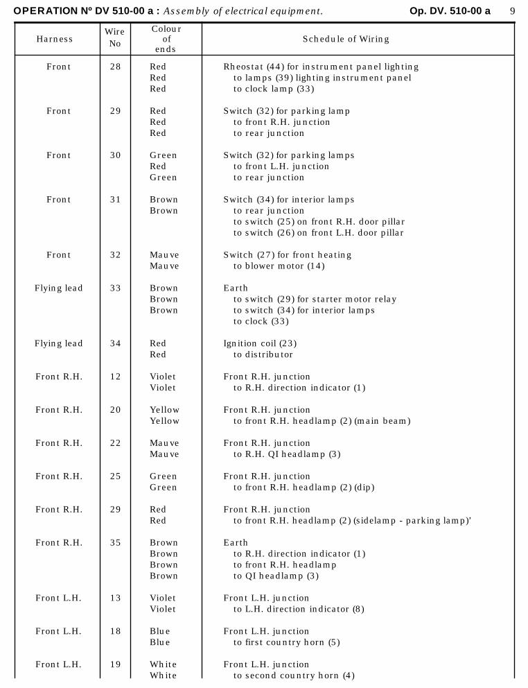
OPERATION Nº DV 510-00 a : Assembly of electrical equipment. Op. DV. 510-00 a 9
HarnessWireNo
Colourof
endsSchedule of Wiring
Front
Front
Front
Front
Front
Flying lead
Flying lead
Front R.H.
Front R.H.
Front R.H.
Front R.H.
Front R.H.
Front R.H.
Front L.H.
Front L.H.
Front L.H.
28
29
30
31
32
33
34
12
20
22
25
29
35
13
18
19
RedRedRed
RedRedRed
GreenRedGreen
BrownBrown
MauveMauve
BrownBrownBrown
RedRed
VioletViolet
YellowYellow
MauveMauve
GreenGreen
RedRed
BrownBrownBrownBrown
VioletViolet
BlueBlue
WhiteWhite
Rheostat (44) for instrument panel lightingto lamps (39) lighting instrument panelto clock lamp (33)
Switch (32) for parking lampto front R.H. junctionto rear junction
Switch (32) for parking lampsto front L.H. junctionto rear junction
Switch (34) for interior lampsto rear junctionto switch (25) on front R.H. door pillarto switch (26) on front L.H. door pillar
Switch (27) for front heatingto blower motor (14)
Earthto switch (29) for starter motor relayto switch (34) for interior lampsto clock (33)
Ignition coil (23)to distributor
Front R.H. junctionto R.H. direction indicator (1)
Front R.H. junctionto front R.H. headlamp (2) (main beam)
Front R.H. junctionto R.H. QI headlamp (3)
Front R.H. junctionto front R.H. headlamp (2) (dip)
Front R.H. junctionto front R.H. headlamp (2) (sidelamp - parking lamp)’
Earthto R.H. direction indicator (1)to front R.H. headlampto QI headlamp (3)
Front L.H. junctionto L.H. direction indicator (8)
Front L.H. junctionto first country horn (5)
Front L.H. junctionto second country horn (4)

OPERATION Nº DV 510-00 a : Assembly of electrical equipment. Op. DV. 510-00 a 11
HarnessWireNo
Colourof
endsSchedule of Wiring
Front L.H.
Front L.H.
Front L.H.
Front L.H.
Front L.H.
Rear
Rear
Rear
Rear
Rear
Rear
Rear
Rear
Rear
Rear
Flying lead
20
23
25’
30
36
7
12
13
16
27
29
30
31
37
38
39
YellowYellow
MauveMauve
GreenGreen
RedRed
Brown
BlackBlack
BlueBlue
WhiteBlue
VioletRedRed
MauveMauveMauve
RedGreen
GreenGreen
BrownBrown
YellowYellow
GreyRed
BlackBlack
Front L.H. junctionto front L.H. headlamp (7) (main beam)
Front L.H. junctionto QI headlamp (6)
Front L.H. junctionto front L.H. headlamp (7) (dip)
Front L.H. junctionto front L.H.. headlamp (7) (sidelamp - parking lamp)
Earthto L.H. direction indicator (8)to front L.H. headlamp (7)to QI headlamp (6)
Rear junctionto interior. lamp (46)
Rear junctionto rear R.H. direction indicator (49)
Rear junctionto rear L.H. direction indicator (52)
Rear junctionto rear R.H. stop lamp (50)to rear L.H. stop lamp (51)
Rear junctionto R.H. number plate lamp (50)to L.H. number plate lamp (51)to boot lamp (47)
Rear junctionto rear R.H. parking lamp (or rear lamp) (50)
Rear junctionto rear L.H. parking lamp (or rear lamp ) (51)
Rear junctionto interior lamp (46)
Fuel gauge (41)to rheostat (45) for fuel gauge
Switch (53) for rear heating ( - 15º C ) (59º F )to blower motor (54) for rear heating ( - 15º C ) (59º F )
OPTIONAL FITTINGS :
1) A compressor horn is fitted on request
Voltage regulator (9) (« BAT » terminal)to horn harness junction
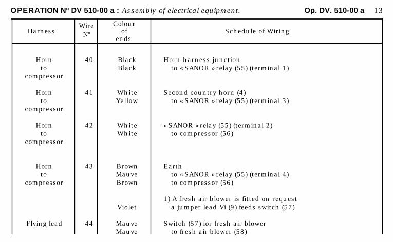
OPERATION Nº DV 510-00 a : Assembly of electrical equipment. Op. DV. 510-00 a 13
HarnessWireNº
Colourof
endsSchedule of Wiring
Hornto
compressor
Hornto
compressor
Hornto
compressor
Hornto
compressor
Flying lead
40
41
42
43
44
BlackBlack
WhiteYellow
WhiteWhite
BrownMauveBrown
Violet
MauveMauve
Horn harness junctionto « SANOR » relay (55) (terminal 1)
Second country horn (4)to « SANOR » relay (55) (terminal 3)
« SANOR » relay (55) (terminal 2)to compressor (56)
Earthto « SANOR » relay (55) (terminal 4)to compressor (56)
1) A fresh air blower is fitted on requesta jumper lead Vi (9) feeds switch (57)
Switch (57) for fresh air blowerto fresh air blower (58)
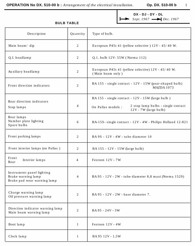
OPERATION No DX. 510-00 b : Arrangement of the electrical installation. Op. DX. 510-00 b 1
DX - DJ - DY - DL Sept. 1967 Dec. 1967
BULB TABLE
Description
Main beam/ dip
Q.I. headlamp
Auxiliary headlamp
Front direction indicators
Rear direction indicators
Quantity
2
2
2
2
Type of bulb.
European P45t 41 (yellow selective ) 12V - 45/40 W.
Q.1. bulb 12V- 55W ( Norma 112)
European P45t 41 (yellow selective) 12V - 45/40 W.( Main beam only )
BA 155 - single contact - 12V - 15W (pear-shaped bulb)MAZDA 1073
BA 155 - single contact - 12V - 15W (large bulb )
Stop lamps 4 On Pallas models : 2 stop lamp bulbs - single contact12V - 7W (large bulb)
Rear lampsNumber plate lightingSpare bulbs
Front parking lamps
Front interior lamps (on Pallas )
6
2
2
BA-15S- single contact - 12V - 4W - Philips Holland 12-821
BA 9S - 12V - 4W - tube diameter 10
BA 155 - 12V - 15W (large bulb)
FrontRear
Interior lamps 4 Festoon 12V - 7W
Instrument panel lightingBrake warning lampBrake pad wear warning lamp
Charge warning lampOil pressure warning lamp
Direction indicator warning lampMain beam warning lamp
Boot lamp
Clock lamp
4
2
2
1
1
BA 95 - 12V - 2W - tube diameter 8,8 maxi (Norma 1529)
BA 95 - 12V - 2W - base diameter 7.
BA 95 - 24V - 3W
Festoon 12V - 4W
BA 95 12V - 1,5W
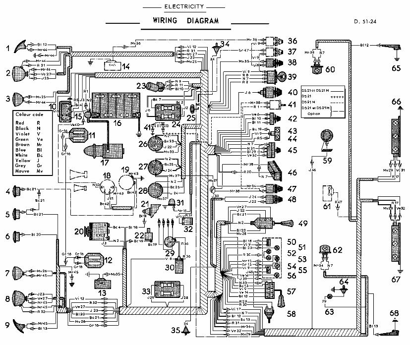
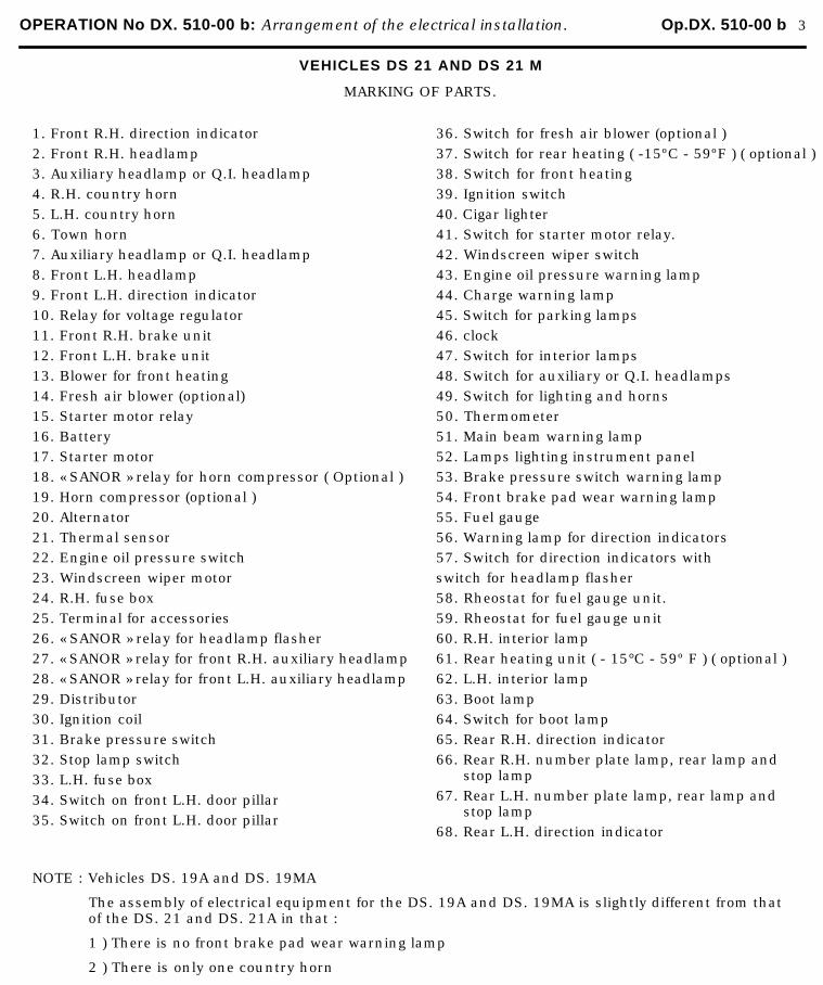
OPERATION No DX. 510-00 b: Arrangement of the electrical installation. Op.DX. 510-00 b 3
VEHICLES DS 21 AND DS 21 M
MARKING OF PARTS.
1. Front R.H. direction indicator
2. Front R.H. headlamp
3. Auxiliary headlamp or Q.I. headlamp
4. R.H. country horn
5. L.H. country horn
6. Town horn
7. Auxiliary headlamp or Q.I. headlamp
8. Front L.H. headlamp
9. Front L.H. direction indicator
10. Relay for voltage regulator
11. Front R.H. brake unit
12. Front L.H. brake unit
13. Blower for front heating
14. Fresh air blower (optional)
15. Starter motor relay
16. Battery
17. Starter motor
18. « SANOR » relay for horn compressor ( Optional )
19. Horn compressor (optional )
20. Alternator
21. Thermal sensor
22. Engine oil pressure switch
23. Windscreen wiper motor
24. R.H. fuse box
25. Terminal for accessories
26. « SANOR » relay for headlamp flasher
27. « SANOR » relay for front R.H. auxiliary headlamp
28. « SANOR » relay for front L.H. auxiliary headlamp
29. Distributor
30. Ignition coil
31. Brake pressure switch
32. Stop lamp switch
33. L.H. fuse box
34. Switch on front L.H. door pillar
35. Switch on front L.H. door pillar
36. Switch for fresh air blower (optional )
37. Switch for rear heating ( -15ºC - 59ºF ) ( optional )
38. Switch for front heating
39. Ignition switch
40. Cigar lighter
41. Switch for starter motor relay.
42. Windscreen wiper switch
43. Engine oil pressure warning lamp
44. Charge warning lamp
45. Switch for parking lamps
46. clock
47. Switch for interior lamps
48. Switch for auxiliary or Q.I. headlamps
49. Switch for lighting and horns
50. Thermometer
51. Main beam warning lamp
52. Lamps lighting instrument panel
53. Brake pressure switch warning lamp
54. Front brake pad wear warning lamp
55. Fuel gauge
56. Warning lamp for direction indicators
57. Switch for direction indicators with
switch for headlamp flasher
58. Rheostat for fuel gauge unit.
59. Rheostat for fuel gauge unit
60. R.H. interior lamp
61. Rear heating unit ( - 15°C - 59º F ) ( optional )
62. L.H. interior lamp
63. Boot lamp
64. Switch for boot lamp
65. Rear R.H. direction indicator
66. Rear R.H. number plate lamp, rear lamp andstop lamp
67. Rear L.H. number plate lamp, rear lamp andstop lamp
68. Rear L.H. direction indicator
NOTE : Vehicles DS. 19A and DS. 19MA
The assembly of electrical equipment for the DS. 19A and DS. 19MA is slightly different from thatof the DS. 21 and DS. 21A in that :
1 ) There is no front brake pad wear warning lamp
2 ) There is only one country horn
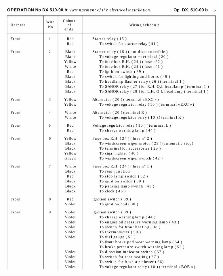
OPERATION No DX 510-00 b: Arrangement of the electrical installation. Op. DX. 510-00 b 5
HarnessWire No
Colourof
ends Wiring schedule
Front 1 Red Starter relay ( 15 )Red To switch for starter relay ( 41 )
Front 2 Black Starter relay ( 15 ) ( not disconnectible )Black To voltage regulator + terminal ( 20 )Yellow To fuse box R.H. ( 24 ) ( fuse nº2 )White To fuse box R.H. ( 24 ) ( fuse nº1 )Red To ignition switch ( 39 )
Black To switch for lighting and horns ( 49 )Black To headlamp flasher relay ( 26 ) ( terminal 1 )Black To SANOR relay ( 27 ) for R.H. Q.I. headlamp ( terminal 1 )Black To SANOR relay ( 28 ) for L.H. Q.I. headlamp ( terminal 1 )
Front 3 Yellow Alternator ( 20 ) ( terminal « EXC » )Yellow To voltage regulator relay ( 10 ) ( terminal « EXC » )
Front 4 White Alternator ( 20 ) (terminal R )White To voltage regulator relay ( 10 ) ( terminal R )
Front 5 Red Voltage regulator relay ( 10 ) ( terminal L )Red To charge warning lamp ( 44 )
Front 6 Yellow Fuse box R.H. ( 24 ) ( fuse nº 2 )Black To windscreen wiper motor ( 23 ) (automatic stop)Black To terminal for accessories ( 25 )Yellow To cigar lighter ( 40 )Green To windscreen wiper switch ( 42 )
Front 7 White Fuse box R.H. ( 24 ) ( fuse nº 1 )Black To rear junctionRed To stop lamp switch ( 32 )
Black To ignition switch ( 39 )Black To parking lamp switch ( 45 )Black To clock ( 46 )
Front 8 Red Ignition switch ( 39 )Violet To ignition coil ( 30 )
Front 9 Violet Ignition switch ( 39 )Violet To charge warning lamp ( 44 )Violet To engine oil pressure warning lamp ( 43 )Violet To switch for front heating ( 38 )Violet To thermometer ( 50 )Violet To fuel gauge ( 56 )
To front brake pad wear warning lamp ( 54 )To brake pressure switch warning lamp ( 53 )
Violet To direction indicator switch ( 57 )Violet To switch for rear heating ( 37 )Violet To switch for fresh air blower ( 36)Violet To voltage regulator relay ( 10 ) ( terminal « BOB » )
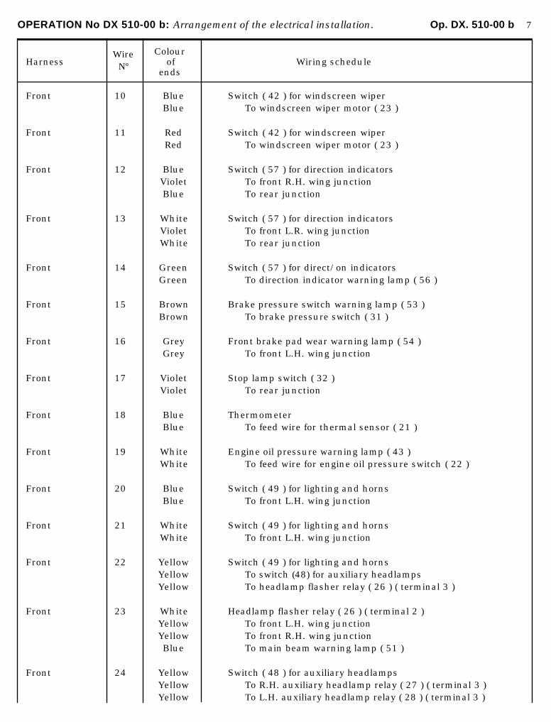
OPERATION No DX 510-00 b: Arrangement of the electrical installation. Op. DX. 510-00 b 7
HarnessWire Nº
Colourof
ends Wiring schedule
Front 10 Blue Switch ( 42 ) for windscreen wiperBlue To windscreen wiper motor ( 23 )
Front 11 Red Switch ( 42 ) for windscreen wiperRed To windscreen wiper motor ( 23 )
Front 12 Blue Switch ( 57 ) for direction indicatorsViolet To front R.H. wing junctionBlue To rear junction
Front 13 White Switch ( 57 ) for direction indicatorsViolet To front L.R. wing junctionWhite To rear junction
Front 14 Green Switch ( 57 ) for direct/on indicatorsGreen To direction indicator warning lamp ( 56 )
Front 15 Brown Brake pressure switch warning lamp ( 53 )Brown To brake pressure switch ( 31 )
Front 16 Grey Front brake pad wear warning lamp ( 54 )Grey To front L.H. wing junction
Front 17 Violet Stop lamp switch ( 32 )Violet To rear junction
Front 18 Blue ThermometerBlue To feed wire for thermal sensor ( 21 )
Front 19 White Engine oil pressure warning lamp ( 43 )White To feed wire for engine oil pressure switch ( 22 )
Front 20 Blue Switch ( 49 ) for lighting and hornsBlue To front L.H. wing junction
Front 21 White Switch ( 49 ) for lighting and hornsWhite To front L.H. wing junction
Front 22 Yellow Switch ( 49 ) for lighting and hornsYellow To switch (48) for auxiliary headlampsYellow To headlamp flasher relay ( 26 ) ( terminal 3 )
Front 23 White Headlamp flasher relay ( 26 ) ( terminal 2 )Yellow To front L.H. wing junctionYellow To front R.H. wing junctionBlue To main beam warning lamp ( 51 )
Front 24 Yellow Switch ( 48 ) for auxiliary headlampsYellow To R.H. auxiliary headlamp relay ( 27 ) ( terminal 3 )Yellow To L.H. auxiliary headlamp relay ( 28 ) ( terminal 3 )
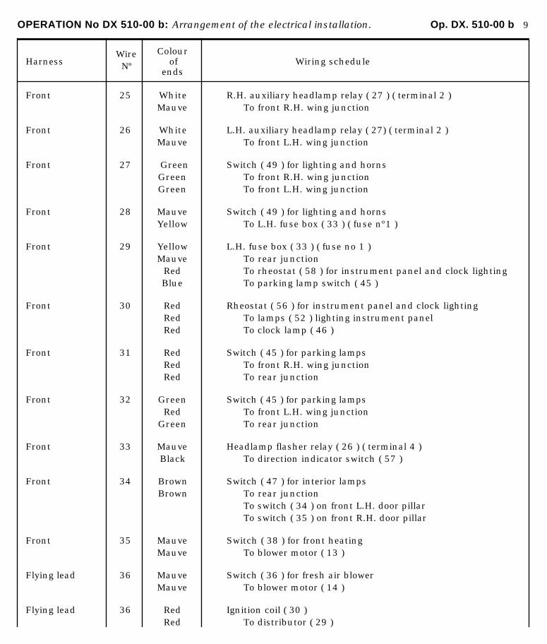
OPERATION No DX 510-00 b: Arrangement of the electrical installation. Op. DX. 510-00 b 9
HarnessWire Nº
Colourof
ends Wiring schedule
Front 25 White R.H. auxiliary headlamp relay ( 27 ) ( terminal 2 )Mauve To front R.H. wing junction
Front 26 White L.H. auxiliary headlamp relay ( 27) ( terminal 2 )Mauve To front L.H. wing junction
Front 27 Green Switch ( 49 ) for lighting and hornsGreen To front R.H. wing junctionGreen To front L.H. wing junction
Front 28 Mauve Switch ( 49 ) for lighting and hornsYellow To L.H. fuse box ( 33 ) ( fuse nº1 )
Front 29 Yellow L.H. fuse box ( 33 ) ( fuse no 1 )Mauve To rear junction
Red To rheostat ( 58 ) for instrument panel and clock lightingBlue To parking lamp switch ( 45 )
Front 30 Red Rheostat ( 56 ) for instrument panel and clock lightingRed To lamps ( 52 ) lighting instrument panelRed To clock lamp ( 46 )
Front 31 Red Switch ( 45 ) for parking lampsRed To front R.H. wing junctionRed To rear junction
Front 32 Green Switch ( 45 ) for parking lampsRed To front L.H. wing junction
Green To rear junction
Front 33 Mauve Headlamp flasher relay ( 26 ) ( terminal 4 )Black To direction indicator switch ( 57 )
Front 34 Brown Switch ( 47 ) for interior lampsBrown To rear junction
To switch ( 34 ) on front L.H. door pillarTo switch ( 35 ) on front R.H. door pillar
Front 35 Mauve Switch ( 38 ) for front heatingMauve To blower motor ( 13 )
Flying lead 36 Mauve Switch ( 36 ) for fresh air blowerMauve To blower motor ( 14 )
Flying lead 36 Red Ignition coil ( 30 )Red To distributor ( 29 )

OPERATION No DX 510-00 b: Arrangement of the electrical installation. Op. DX. 510-00 b 11
HarnessWire Nº
Colourof
ends Wiring schedule
Flying lead 37 Mauve EarthMauve To front R.H. auxiliary headlamp relay ( 27 ) ( terminal 4 )Mauve To front L.H. auxiliary headlamp relay ( 26 ) ( terminal 4 )
Flying lead 38 Brown EarthBrown To switch ( 41 ) for starter motor relayBrown To switch ( 47 ) for interior lampsBrown To clock ( 46 )
Flying lead 39 Yellow EarthYellow To switch ( 5’7 ) for direction indicators
Flying lead 40 Green Starter motor relay ( 15 )Black To horn compressor relay ( 16 ) ( terminal 1 )
Horn to 41 White R.H. country horn ( 4 )Compressor White To link wire
Yellow To « SANOR » relay ( 18 ) ( terminal 3 )
Horn to 42 White « SANOR » relay ( 18 ) ( terminal 3 )Compressor White To compressor ( 19 )
Horn to 43 Brown « SANOR » relay ( 16 ) ( terminal 4 )Compressor Brown To compressor ( 19 )
Brown To earth
Front R.H. 12 Violet Front R.H. junctionBlue To R.H. direction indicator ( 1 )
Front R.H. 23 Yellow Front R.H. junctionYellow To front R.H. headlamp ( 2 ) ( main beam )
Front R.H. 25 Mauve Front R.H. junctionMauve To R.H. auxiliary headlamp ( 3 )
Front R.H. 27 Green Front R.H. junctionGreen To front R.H. headlamp ( 2 ) ( dip )
Front R.H. 31 Red Front R.H. junctionRed To front R.H. headlamp ( 2 ) ( sidelamp - parking lamp )
Front R.H. 44 Brown EarthTo front R.H. direction indicator ( 1 )To front R.H. headlamp ( 2 ) ( sidelamp )To front R.H. headlamp ( 2 ) ( main beam-dip )To auxiliary headlamp ( 3 )
Front L.H. 13 Violet Front L.H. junctionBlue To front L.H. direction indicator ( 9 )
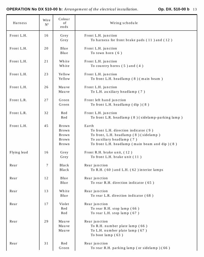
OPERATION No DX 510-00 b: Arrangement of the electrical installation. Op. DX. 510-00 b 13
HarnessWire Nº
Colourof
ends Wiring schedule
Front L.H. 16 Grey Front L.H. junctionGrey To harness for front brake pads ( 11 ) and ( 12 )
Front L.H. 20 Blue Front L.H. junctionBlue To town horn ( 6 )
Front L.H. 21 White Front L.H. junctionWhite To country horns ( 5 ) and ( 4 )
Front L.H. 23 Yellow Front L.H. junctionYellow To front L.H. headlamp ( 8 ) ( main beam )
Front L.H. 26 Mauve Front L.H. junctionMauve To L.H. auxiliary headlamp ( 7 )
Front L.R. 27 Green Front left hand junctionGreen To front L.H. headlamp ( dip ) ( 8 )
Front L.R. 32 Red Front L.H. junctionRed To front L.R. headlamp ( 8 ) ( sidelamp-parking lamp )
Front L.H. 45 Brown EarthBrown To front L.H. direction indicator ( 9 )Brown To front, L.H. headlamp ( 8 ) ( sidelamp )Brown To auxiliary headlamp ( 7 )Brown To front L.H. headlamp ( main beam and dip ) ( 8 )
Flying lead 16 Grey Front R.H. brake unit, ( 12 )Grey To front L.H. brake unit ( 11 )
Rear 7 Black Rear junctionBlack To R.H. ( 60 ) and L.H. ( 62 ) interior lamps
Rear 12 Blue Rear junctionBlue To rear R.H. direction indicator ( 65 )
Rear 13 White Rear junctionBlue To rear L.R. direction indicator ( 68 )
Rear 17 Violet Rear junctionRed To rear R.H. stop lamp ( 66 )Red To rear L.H. stop lamp ( 67 )
Rear 29 Mauve Rear junctionMauve To R.H. number plate lamp ( 66 )Mauve To L.H. number plate lamp ( 67 )
To boot lamp ( 63 )
Rear 31 Red Rear junctionGreen To rear R.H. parking lamp ( or sidelamp ) ( 66 )
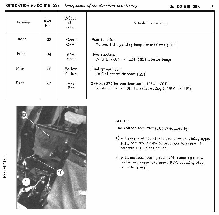
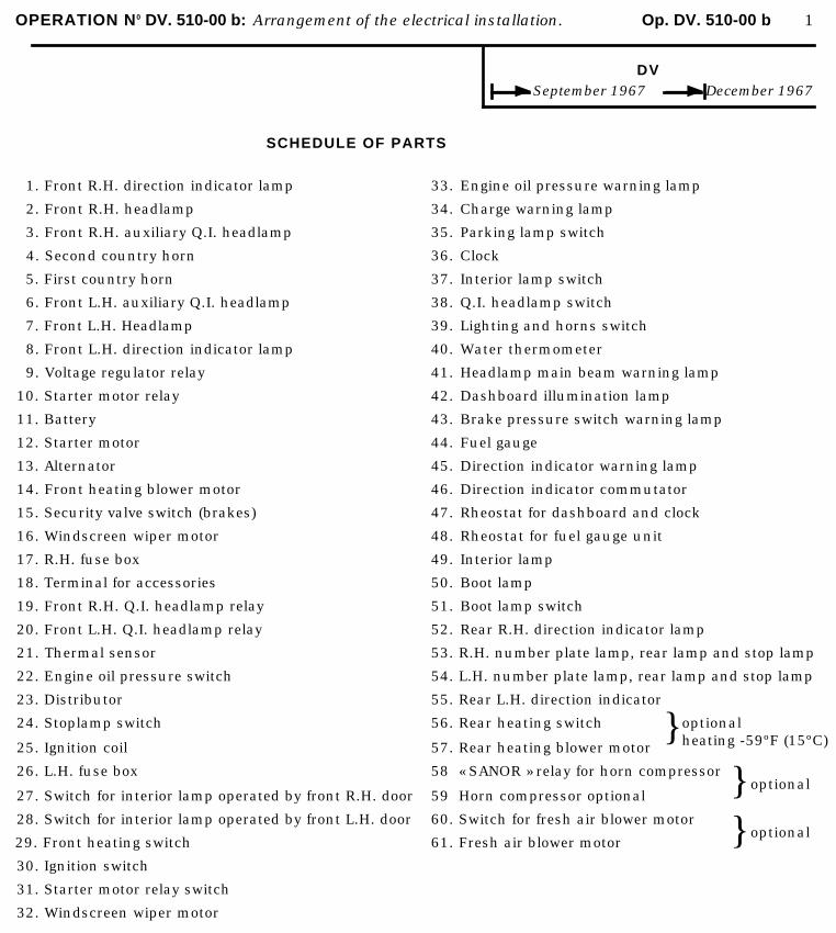
OPERATION N0 DV. 510-00 b: Arrangement of the electrical installation. Op. DV. 510-00 b 1
DV September 1967 December 1967
SCHEDULE OF PARTS
1. Front R.H. direction indicator lamp
2. Front R.H. headlamp
3. Front R.H. auxiliary Q.I. headlamp
4. Second country horn
5. First country horn
6. Front L.H. auxiliary Q.I. headlamp
7. Front L.H. Headlamp
8. Front L.H. direction indicator lamp
9. Voltage regulator relay
10. Starter motor relay
11. Battery
12. Starter motor
13. Alternator
14. Front heating blower motor
15. Security valve switch (brakes)
16. Windscreen wiper motor
17. R.H. fuse box
18. Terminal for accessories
19. Front R.H. Q.I. headlamp relay
20. Front L.H. Q.I. headlamp relay
21. Thermal sensor
22. Engine oil pressure switch
23. Distributor
33.
34.
35.
36.
37.
38.
39.
40.
41.
42.
43.
44.
45.
46.
47.
48.
49.
50.
51.
52.
53.
54.
55.
Engine oil pressure warning lamp
Charge warning lamp
Parking lamp switch
Clock
Interior lamp switch
Q.I. headlamp switch
Lighting and horns switch
Water thermometer
Headlamp main beam warning lamp
Dashboard illumination lamp
Brake pressure switch warning lamp
Fuel gauge
Direction indicator warning lamp
Direction indicator commutator
Rheostat for dashboard and clock
Rheostat for fuel gauge unit
Interior lamp
Boot lamp
Boot lamp switch
Rear R.H. direction indicator lamp
R.H. number plate lamp, rear lamp and stop lamp
L.H. number plate lamp, rear lamp and stop lamp
Rear L.H. direction indicator
24. Stoplamp switch
25. Ignition coil
56.
57.
Rear heating switch
Rear heating blower motor} optional
heating -59ºF (15ºC)
26. L.H. fuse box
27. Switch for interior lamp operated by front R.H. door
28. Switch for interior lamp operated by front L.H. door
29. Front heating switch
30. Ignition switch
31. Starter motor relay switch
32. Windscreen wiper motor
58
59
60.
61.
« SANOR » relay for horn compressor
Horn compressor optional
Switch for fresh air blower motor
Fresh air blower motor
}}
optional
optional
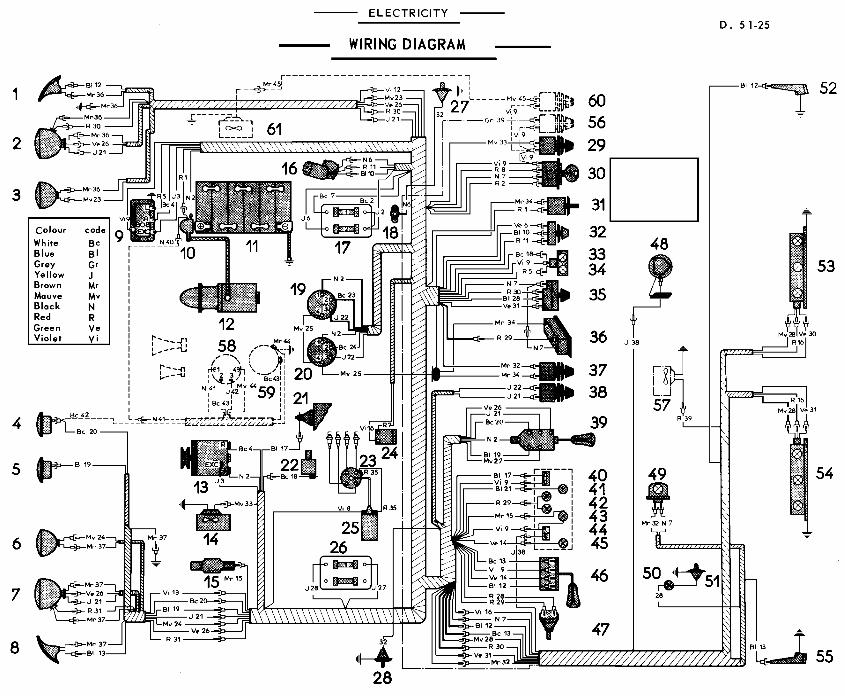
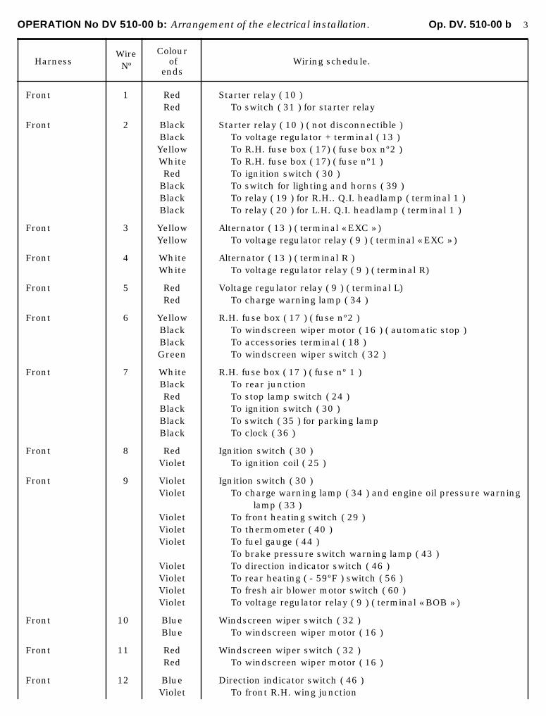
OPERATION No DV 510-00 b: Arrangement of the electrical installation. Op. DV. 510-00 b 3
HarnessWire Nº
Colourof
ends Wiring schedule.
Front 1 Red Starter relay ( 10 )Red To switch ( 31 ) for starter relay
Front 2 Black Starter relay ( 10 ) ( not disconnectible )Black To voltage regulator + terminal ( 13 )Yellow To R.H. fuse box ( 17) ( fuse box nº2 )White To R.H. fuse box ( 17) ( fuse nº1 )Red To ignition switch ( 30 )
Black To switch for lighting and horns ( 39 )Black To relay ( 19 ) for R.H.. Q.I. headlamp ( terminal 1 )Black To relay ( 20 ) for L.H. Q.I. headlamp ( terminal 1 )
Front 3 Yellow Alternator ( 13 ) ( terminal « EXC » )Yellow To voltage regulator relay ( 9 ) ( terminal « EXC » )
Front 4 White Alternator ( 13 ) ( terminal R )White To voltage regulator relay ( 9 ) ( terminal R)
Front 5 Red Voltage regulator relay ( 9 ) ( terminal L)Red To charge warning lamp ( 34 )
Front 6 Yellow R.H. fuse box ( 17 ) ( fuse nº2 )Black To windscreen wiper motor ( 16 ) ( automatic stop )Black To accessories terminal ( 18 )Green To windscreen wiper switch ( 32 )
Front 7 White R.H. fuse box ( 17 ) ( fuse nº 1 )Black To rear junctionRed To stop lamp switch ( 24 )
Black To ignition switch ( 30 )Black To switch ( 35 ) for parking lampBlack To clock ( 36 )
Front 8 Red Ignition switch ( 30 )Violet To ignition coil ( 25 )
Front 9 Violet Ignition switch ( 30 )Violet To charge warning lamp ( 34 ) and engine oil pressure warning
lamp ( 33 )Violet To front heating switch ( 29 )Violet To thermometer ( 40 )Violet To fuel gauge ( 44 )
To brake pressure switch warning lamp ( 43 )Violet To direction indicator switch ( 46 )Violet To rear heating ( - 59ºF ) switch ( 56 )Violet To fresh air blower motor switch ( 60 )Violet To voltage regulator relay ( 9 ) ( terminal « BOB » )
Front 10 Blue Windscreen wiper switch ( 32 )Blue To windscreen wiper motor ( 16 )
Front 11 Red Windscreen wiper switch ( 32 )Red To windscreen wiper motor ( 16 )
Front 12 Blue Direction indicator switch ( 46 )Violet To front R.H. wing junction
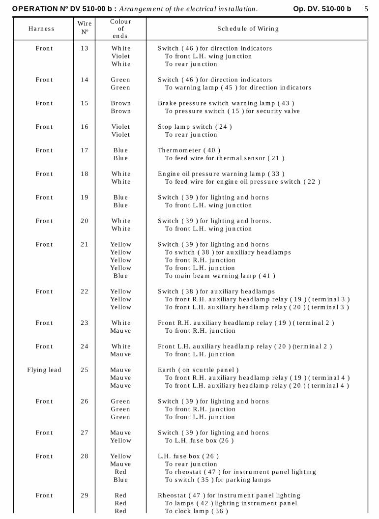
OPERATION Nº DV 510-00 b : Arrangement of the electrical installation. Op. DV. 510-00 b 5
HarnessWireNº
Colourof
endsSchedule of Wiring
Front
Front
Front
Front
Front
Front
Front
Front
Front
Front
Front
Front
Flying lead
Front
Front
Front
Front
13
14
15
16
17
18
19
20
21
22
23
24
25
26
27
28
29
WhiteVioletWhite
GreenGreen
BrownBrown
VioletViolet
BlueBlue
WhiteWhite
BlueBlue
WhiteWhite
YellowYellowYellowYellowBlue
YellowYellowYellow
WhiteMauve
WhiteMauve
MauveMauveMauve
GreenGreenGreen
MauveYellow
YellowMauve
RedBlue
RedRedRed
Switch ( 46 ) for direction indicatorsTo front L.H. wing junctionTo rear junction
Switch ( 46 ) for direction indicatorsTo warning lamp ( 45 ) for direction indicators
Brake pressure switch warning lamp ( 43 )To pressure switch ( 15 ) for security valve
Stop lamp switch ( 24 )To rear junction
Thermometer ( 40 )To feed wire for thermal sensor ( 21 )
Engine oil pressure warning lamp ( 33 )To feed wire for engine oil pressure switch ( 22 )
Switch ( 39 ) for lighting and hornsTo front L.H. wing junction
Switch ( 39 ) for lighting and horns.To front L.H. wing junction
Switch ( 39 ) for lighting and hornsTo switch ( 38 ) for auxiliary headlampsTo front R.H. junctionTo front L.H. junctionTo main beam warning lamp ( 41 )
Switch ( 38 ) for auxiliary headlampsTo front R.H. auxiliary headlamp relay ( 19 ) ( terminal 3 )To front L.H. auxiliary headlamp relay ( 20 ) ( terminal 3 )
Front R.H. auxiliary headlamp relay ( 19 ) ( terminal 2 )To front R.H. junction
Front L.H. auxiliary headlamp relay ( 20 ) (terminal 2 )To front L.H. junction
Earth ( on scuttle panel )To front R.H. auxiliary headlamp relay ( 19 ) ( terminal 4 )To front L.H. auxiliary headlamp relay ( 20 ) ( terminal 4 )
Switch ( 39 ) for lighting and hornsTo front R.H. junctionTo front L.H. junction
Switch ( 39 ) for lighting and hornsTo L.H. fuse box (26 )
L.H. fuse box ( 26 )To rear junctionTo rheostat ( 47 ) for instrument panel lightingTo switch ( 35 ) for parking lamps
Rheostat ( 47 ) for instrument panel lightingTo lamps ( 42 ) lighting instrument panelTo clock lamp ( 36 )
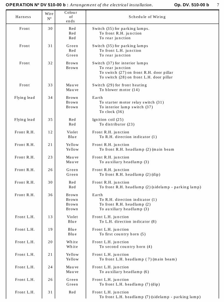
OPERATION Nº DV 510-00 b : Arrangement of the electrical installation. Op. DV. 510-00 b 7
HarnessWireNº
Colourof
endsSchedule of Wiring
Front
Front
Front
Front
Flying lead
Flying lead
Front R.H.
Front R.H.
Front R.H.
Front R.H.
Front R.H.
Front R.H.
Front L.H.
Front L.H.
Front L.H.
Front L.H.
Front L.H.
Front L.H.
Front L.H.
30
31
32
33
34
35
12
21
23
26
30
36
13
19
20
21
24
26
31
RedRedRed
GreenRed
Green
BrownBrown
MauveMauve
BrownBrownBrown
RedRed
VioletBlue
YellowYellow
MauveMauve
GreenGreen
RedRed
BrownBrownBrownBrown
VioletBlue
BlueBlue
WhiteWhite
YellowYellow
MauveMauve
GreenGreen
Red
Switch (35) for parking lamps.To front R.H. junctionTo rear junction
Switch (35) for parking lampsTo front L.H. junctionTo rear junction
Switch (37) for interior lampsTo rear junctionTo switch (27) on front R.H. door pillarTo switch (28) on front L.H. door pillar
Switch (29) for front heatingTo blower motor (14)
EarthTo starter motor relay switch (31)To interior lamp switch (37)To clock (36)
Ignition coil (25)To distributor (23)
Front R.H. junctionTo R.H. direction indicator (1)
Front R.H. junctionTo front R.H. headlamp (2) (main beam
Front R.H. junctionTo auxiliary headlamp (3)
Front R.H. junctionTo front R.H. headlamp (2) (dip)
Front R.H. junctionTo front R.H. headlamp (2) (sidelamp - parking lamp)
EarthTo R.H. direction indicator (1)To front R.H. headlamp (2)To auxiliary headlamp (3)
Front L.H. junctionTo L.H. direction indicator (8)
Front L.H. junctionTo first country horn (5)
Front L.H. junctionTo second country horn (4)
Front L.H. junctionTo front L.H. headlamp ( 7) (main beam)
Front L.H. junctionTo auxiliary headlamp (6)
Front L.H. junctionTo front L.H. headlamp (7) (dip)
Front L.H. junctionTo front L.H. headlamp (7) (sidelamp - parking lamp)
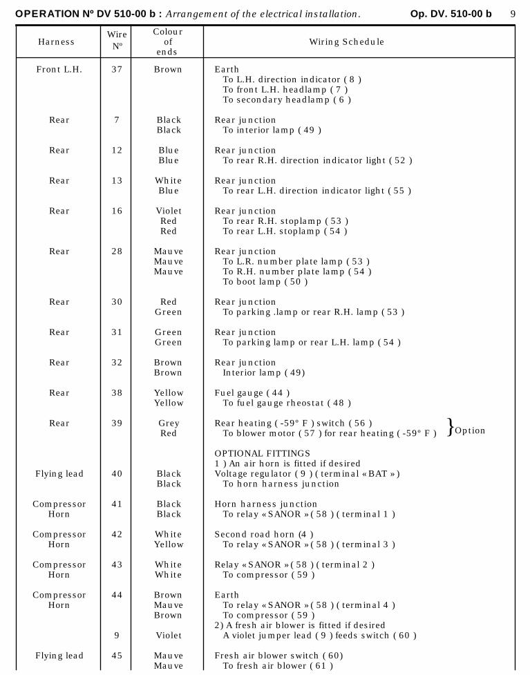
OPERATION Nº DV 510-00 b : Arrangement of the electrical installation. Op. DV. 510-00 b 9
HarnessWireNº
Colourof
endsWiring Schedule
Front L.H.
Rear
Rear
Rear
Rear
Rear
Rear
Rear
Rear
Rear
Rear
Flying lead
CompressorHorn
CompressorHorn
CompressorHorn
CompressorHorn
Flying lead
37
7
12
13
16
28
30
31
32
38
39
40
41
42
43
44
9
45
Brown
BlackBlack
BlueBlue
WhiteBlue
VioletRedRed
MauveMauveMauve
RedGreen
GreenGreen
BrownBrown
YellowYellow
GreyRed
BlackBlack
BlackBlack
WhiteYellow
WhiteWhite
BrownMauveBrown
Violet
MauveMauve
EarthTo L.H. direction indicator ( 8 )To front L.H. headlamp ( 7 )To secondary headlamp ( 6 )
Rear junctionTo interior lamp ( 49 )
Rear junctionTo rear R.H. direction indicator light ( 52 )
Rear junctionTo rear L.H. direction indicator light ( 55 )
Rear junctionTo rear R.H. stoplamp ( 53 )To rear L.H. stoplamp ( 54 )
Rear junctionTo L.R. number plate lamp ( 53 )To R.H. number plate lamp ( 54 )To boot lamp ( 50 )
Rear junctionTo parking .lamp or rear R.H. lamp ( 53 )
Rear junctionTo parking lamp or rear L.H. lamp ( 54 )
Rear junctionInterior lamp ( 49)
Fuel gauge ( 44 )To fuel gauge rheostat ( 48 )
Rear heating ( -59º F ) switch ( 56 )To blower motor ( 57 ) for rear heating ( -59º F )
OPTIONAL FITTINGS1 ) An air horn is fitted if desiredVoltage regulator ( 9 ) ( terminal « BAT » )
To horn harness junction
Horn harness junctionTo relay « SANOR » ( 58 ) ( terminal 1 )
Second road horn (4 )To relay « SANOR » ( 58 ) ( terminal 3 )
Relay « SANOR » ( 58 ) ( terminal 2 )To compressor ( 59 )
EarthTo relay « SANOR » ( 58 ) ( terminal 4 )To compressor ( 59 )
2) A fresh air blower is fitted if desiredA violet jumper lead ( 9 ) feeds switch ( 60 )
Fresh air blower switch ( 60)To fresh air blower ( 61 )
} Option
OPERATION No DX. 510-00~ : Arrangement of the electrical installation. Op. DX. 510-00~ i
DX - DJ - DY - DL - DV
*December 1967-+October 1968
ARRANGEMENT OF THE ELECTRICAL INSTALLATION
h
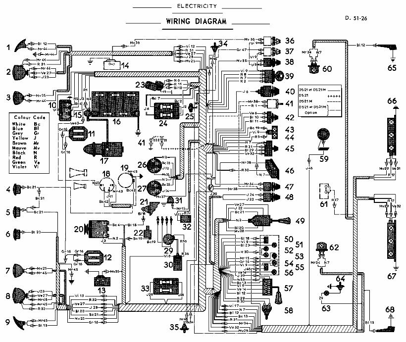
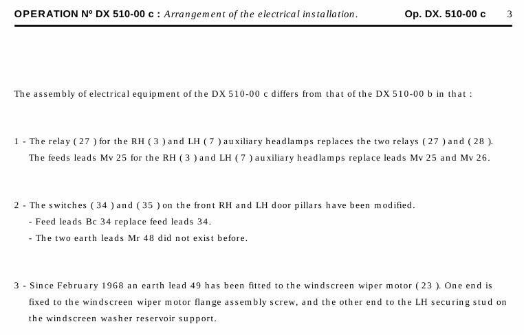
OPERATION Nº DX 510-00 c : Arrangement of the electrical installation. Op. DX. 510-00 c 3
The assembly of electrical equipment of the DX 510-00 c differs from that of the DX 510-00 b in that :
1 - The relay ( 27 ) for the RH ( 3 ) and LH ( 7 ) auxiliary headlamps replaces the two relays ( 27 ) and ( 28 ).
The feeds leads Mv 25 for the RH ( 3 ) and LH ( 7 ) auxiliary headlamps replace leads Mv 25 and Mv 26.
2 - The switches ( 34 ) and ( 35 ) on the front RH and LH door pillars have been modified.
- Feed leads Bc 34 replace feed leads 34.
- The two earth leads Mr 48 did not exist before.
3 - Since February 1968 an earth lead 49 has been fitted to the windscreen wiper motor ( 23 ). One end is
fixed to the windscreen wiper motor flange assembly screw, and the other end to the LH securing stud on
the windscreen washer reservoir support.
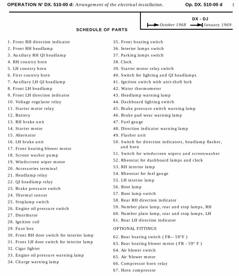
OPERATION N0 DX. 510-00 d: Arrangement of the electrical installation. Op. DX. 510-00 d 1
DX - DJOctober 1968 January 1969
SCHEDULE OF PARTS
1. Front RH direction indicator
2. Front RH headlamp
3. Auxiliary RH QI headlamp
4. RH country horn
5. LH country horn
6. First country horn
7. Auxiliary LH QI headlamp
8. Front LH headlamp
9. Front LH direction indicator
10. Voltage regulator relay
11. Starter motor relay
12. Battery
13. RH brake unit
14. Starter motor
15. Alternator
16. LH brake unit
17. Front heating blower motor
18. Screen washer pump
19. Windscreen wiper motor
20. Accessories terminal
21. Headlamp relay
22. QI headlamp relay
23. Brake pressure switch
24. Thermal sensor
25. Stoplamp switch
26. Engine oil pressure switch
27. Distributor
28. Ignition coil
29. Fuse box
30. Front RH door switch for interior lamp
31. Front LH door switch for interior lamp
32. Cigar lighter
33. Engine oil pressure warning lamp
34. Charge warning lamp
35. Front heating switch
36. Interior lamps switch
37. Parking lamps switch
38. Clock
39. Starter motor relay switch
40. Switch for lighting and QI headlamps
41. Ignition switch with anti-theft lock
42. Water thermometer
43. Headlamp warning lamp
44. Dashboard lighting switch
45. Brake pressure switch warning lamp
46. Brake pad wear warning lamp
47. Fuel gauge
48. Direction indicator warning lamp
49. Flasher unit
50. Switch for direction indicators, headlamp flasher,and horn
51. Switch for windscreen wipers and screenwasher
52. Rheostat for dashboard lamps and clock
53. RH interior lamp
54. Rheostat for fuel gauge
55. LH interior lamp
56. Boot lamp
57. Boot lamp switch
58. Rear RH direction indicator
59. Number plate lamp, rear and stop lamps, RH
60. Number plate lamp, rear and stop lamps, LH
61. Rear LH direction indicator
OPTIONAL FITTINGS
62. Rear heating switch ( FR-- 59ºF )
63. Rear heating blower motor ( FR - 59º F )
64. Air blower switch
65. Air ‘blower motor
66. Compressor horn relay
67. Horn compressor
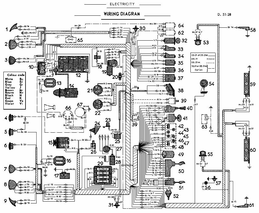
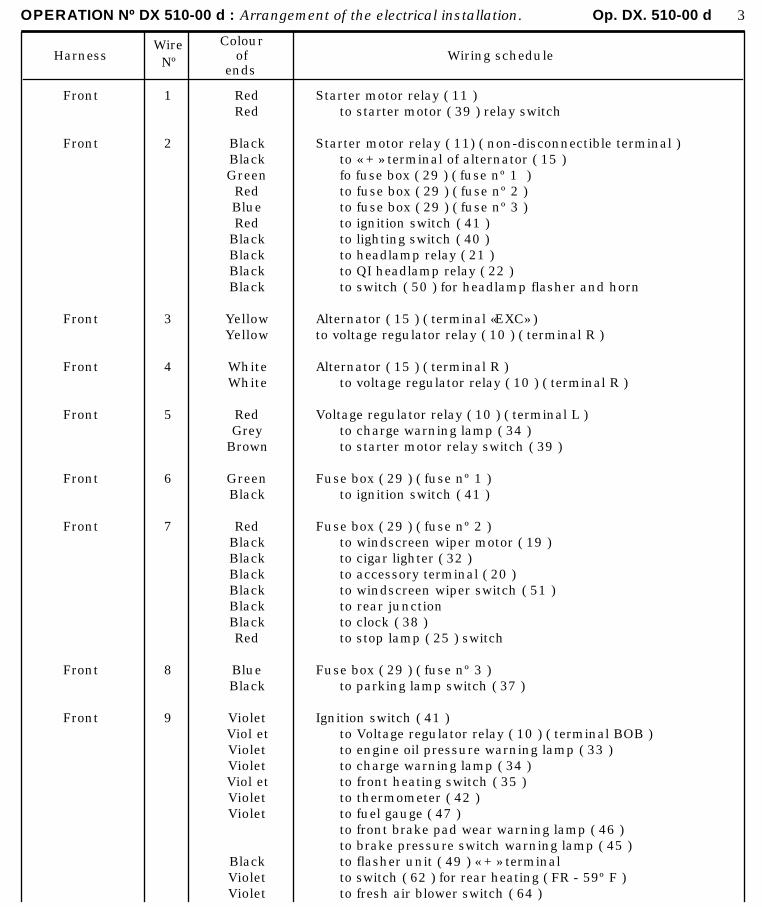
OPERATION Nº DX 510-00 d : Arrangement of the electrical installation. Op. DX. 510-00 d 3
HarnessWireNº
Colourof
endsWiring schedule
Front
Front
Front
Front
Front
Front
Front
Front
Front
1
2
3
4
5
6
7
8
9
RedRed
BlackBlackGreenRedBlueRed
BlackBlackBlackBlack
YellowYellow
WhiteWhite
RedGrey
Brown
GreenBlack
RedBlackBlackBlackBlackBlackBlackRed
BlueBlack
VioletViol etVioletVioletViol etVioletViolet
BlackVioletViolet
Starter motor relay ( 11 )to starter motor ( 39 ) relay switch
Starter motor relay ( 11) ( non-disconnectible terminal )to « + » terminal of alternator ( 15 )fo fuse box ( 29 ) ( fuse nº 1 )to fuse box ( 29 ) ( fuse nº 2 )to fuse box ( 29 ) ( fuse nº 3 )to ignition switch ( 41 )to lighting switch ( 40 )to headlamp relay ( 21 )to QI headlamp relay ( 22 )to switch ( 50 ) for headlamp flasher and horn
Alternator ( 15 ) ( terminal «EXC» )to voltage regulator relay ( 10 ) ( terminal R )
Alternator ( 15 ) ( terminal R )to voltage regulator relay ( 10 ) ( terminal R )
Voltage regulator relay ( 10 ) ( terminal L )to charge warning lamp ( 34 )to starter motor relay switch ( 39 )
Fuse box ( 29 ) ( fuse nº 1 )to ignition switch ( 41 )
Fuse box ( 29 ) ( fuse nº 2 )to windscreen wiper motor ( 19 )to cigar lighter ( 32 )to accessory terminal ( 20 )to windscreen wiper switch ( 51 )to rear junctionto clock ( 38 )to stop lamp ( 25 ) switch
Fuse box ( 29 ) ( fuse nº 3 )to parking lamp switch ( 37 )
Ignition switch ( 41 )to Voltage regulator relay ( 10 ) ( terminal BOB )to engine oil pressure warning lamp ( 33 )to charge warning lamp ( 34 )to front heating switch ( 35 )to thermometer ( 42 )to fuel gauge ( 47 )to front brake pad wear warning lamp ( 46 )to brake pressure switch warning lamp ( 45 )to flasher unit ( 49 ) « + » terminalto switch ( 62 ) for rear heating ( FR - 59º F )to fresh air blower switch ( 64 )
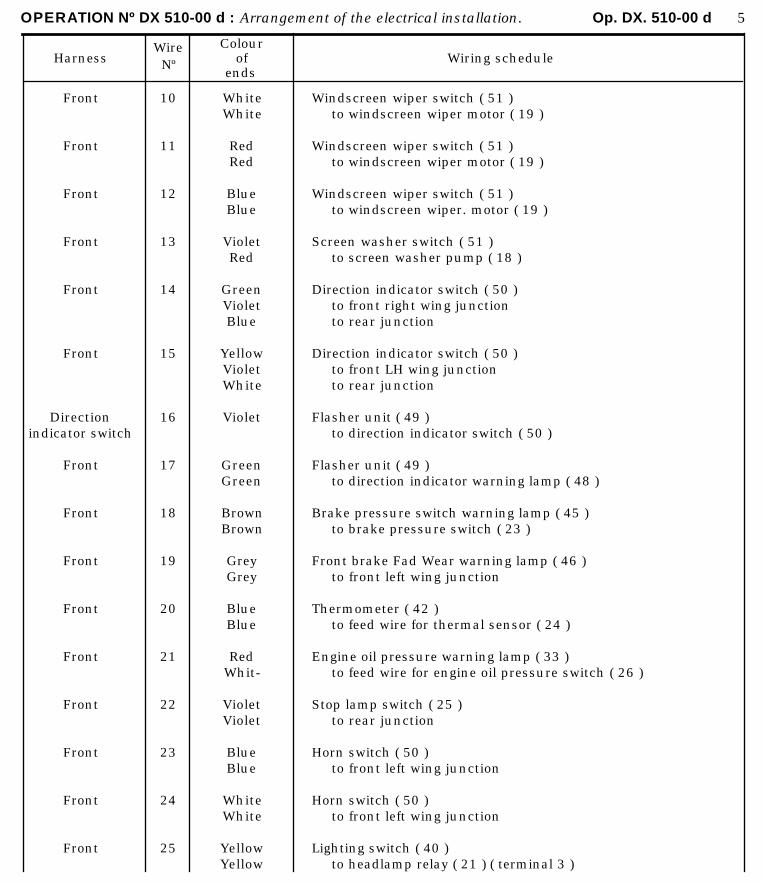
OPERATION Nº DX 510-00 d : Arrangement of the electrical installation. Op. DX. 510-00 d 5
HarnessWireNº
Colourof
endsWiring schedule
Front
Front
Front
Front
Front
Front
Directionindicator switch
Front
Front
Front
Front
Front
Front
Front
Front
Front
10
11
12
13
14
15
16
17
18
19
20
21
22
23
24
25
WhiteWhite
RedRed
BlueBlue
VioletRed
GreenVioletBlue
YellowVioletWhite
Violet
GreenGreen
BrownBrown
GreyGrey
BlueBlue
RedWhit-
VioletViolet
BlueBlue
WhiteWhite
YellowYellow
Windscreen wiper switch ( 51 )to windscreen wiper motor ( 19 )
Windscreen wiper switch ( 51 )to windscreen wiper motor ( 19 )
Windscreen wiper switch ( 51 )to windscreen wiper. motor ( 19 )
Screen washer switch ( 51 )to screen washer pump ( 18 )
Direction indicator switch ( 50 )to front right wing junctionto rear junction
Direction indicator switch ( 50 )to front LH wing junctionto rear junction
Flasher unit ( 49 )to direction indicator switch ( 50 )
Flasher unit ( 49 )to direction indicator warning lamp ( 48 )
Brake pressure switch warning lamp ( 45 )to brake pressure switch ( 23 )
Front brake Fad Wear warning lamp ( 46 )to front left wing junction
Thermometer ( 42 )to feed wire for thermal sensor ( 24 )
Engine oil pressure warning lamp ( 33 )to feed wire for engine oil pressure switch ( 26 )
Stop lamp switch ( 25 )to rear junction
Horn switch ( 50 )to front left wing junction
Horn switch ( 50 )to front left wing junction
Lighting switch ( 40 )to headlamp relay ( 21 ) ( terminal 3 )
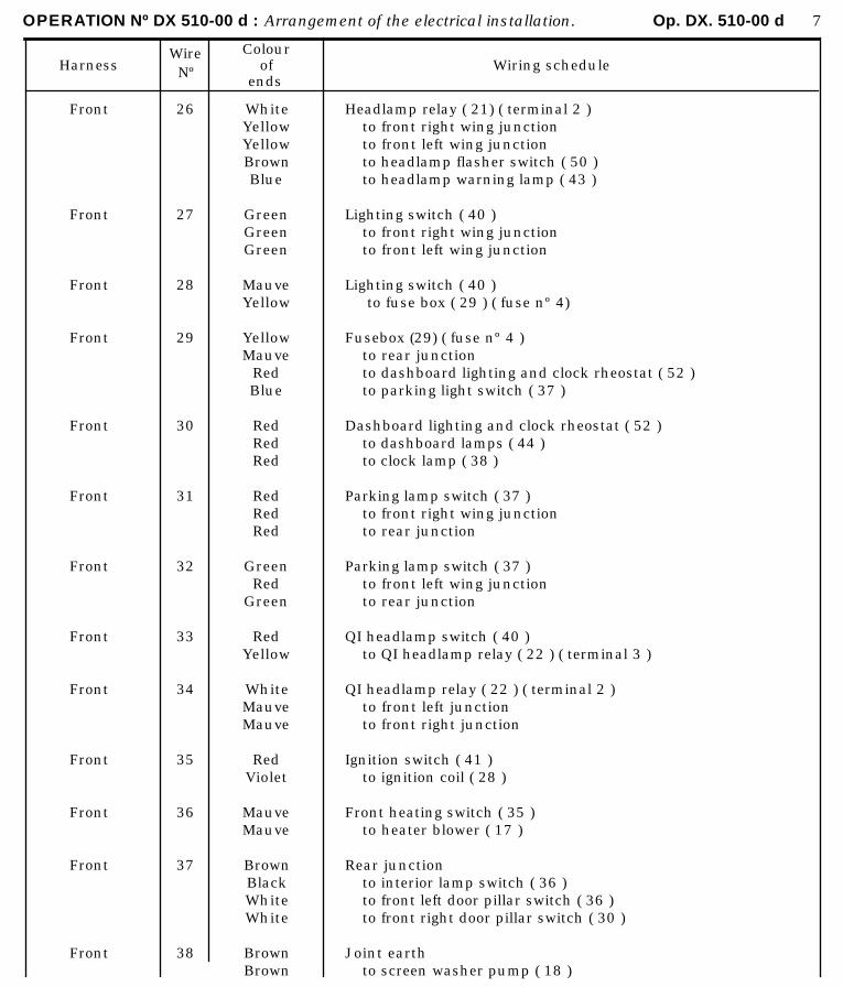
OPERATION Nº DX 510-00 d : Arrangement of the electrical installation. Op. DX. 510-00 d 7
HarnessWireNº
Colourof
endsWiring schedule
Front
Front
Front
Front
Front
Front
Front
Front
Front
Front
Front
Front
Front
26
27
28
29
30
31
32
33
34
35
36
37
38
WhiteYellowYellowBrownBlue
GreenGreenGreen
MauveYellow
YellowMauve
RedBlue
RedRedRed
RedRedRed
GreenRed
Green
RedYellow
WhiteMauveMauve
RedViolet
MauveMauve
BrownBlackWhiteWhite
BrownBrown
Headlamp relay ( 21) ( terminal 2 )to front right wing junctionto front left wing junctionto headlamp flasher switch ( 50 )to headlamp warning lamp ( 43 )
Lighting switch ( 40 )to front right wing junctionto front left wing junction
Lighting switch ( 40 ) to fuse box ( 29 ) ( fuse nº 4)
Fusebox (29) ( fuse nº 4 )to rear junctionto dashboard lighting and clock rheostat ( 52 )to parking light switch ( 37 )
Dashboard lighting and clock rheostat ( 52 )to dashboard lamps ( 44 )to clock lamp ( 38 )
Parking lamp switch ( 37 )to front right wing junctionto rear junction
Parking lamp switch ( 37 )to front left wing junctionto rear junction
QI headlamp switch ( 40 )to QI headlamp relay ( 22 ) ( terminal 3 )
QI headlamp relay ( 22 ) ( terminal 2 )to front left junctionto front right junction
Ignition switch ( 41 )to ignition coil ( 28 )
Front heating switch ( 35 )to heater blower ( 17 )
Rear junctionto interior lamp switch ( 36 )to front left door pillar switch ( 36 )to front right door pillar switch ( 30 )
Joint earthto screen washer pump ( 18 )
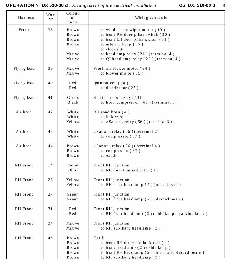
OPERATION Nº DX 510-00 d : Arrangement of the electrical installation. Op. DX. 510-00 d 9
HarnessWireNº
Colourof
endsWiring schedule
Front
Flying lead
Flying lead
Flying lead
Air horn
Air horn
Air horn
RH Front
RH Front
RH Front
RH Front
RH Front
RH Front
38
39
40
41
42
43
44
14
26
27
31
34
45
BrownBrownBrownBrown
MauveMauve
MauveMauve
RedRed
GreenBlack
WhiteWhiteYellow
WhiteWhite
BrownBrownBrown
VioletBlue
YellowYellow
GreenGreen
RedRed
MauveMauve
BrownBrownBrownBrownBrown
to windscreen wiper motor ( 19 )to front RH door pillar switch ( 30 )to front LH door pillar switch ( 31 )to interior lamp ( 36 )to clock ( 38 )to headlamp relay ( 21 ) ( terminal 4 )to QI headlamp relay ( 22 ) ( terminal 4 )
Fresh air blower motor ( 64 )to blower motor ( 65 )
Ignition coil ( 28 )to distributor ( 27 )
Starter motor relay ( 11)to horn compressor ( 66 ) ( terminal 1 )
RH road horn ( 4 )to link wireto « Sanor » relay ( 66 ) ( terminal 3 )
« Sanor » relay ( 66 ) ( terminal 2)to compressor ( 67 )
« Sanor » relay ( 66 ) ( terminal 4 )to compressor ( 67 )to earth
Front RH junctionto RH direction indicator ( 1 )
Front RH junctionto RH front headlamp ( 4 ) ( main beam )
Front RH junctionto RH front headlamp ( 2 ) ( dipped beam)
Front RH junctionto RH front headlamp ( 2 ) ( side lamp - parking lamp )
Front RH junctionto RH auxiliary headlamp ( 3 )
Earthto front RH direction indicator ( 1 )to front headlamp ( 2 ) ( side lamp )to front RH headlamp ( 2 ) ( main and dipped beam )to RH auxiliary headlamp ( 3 )
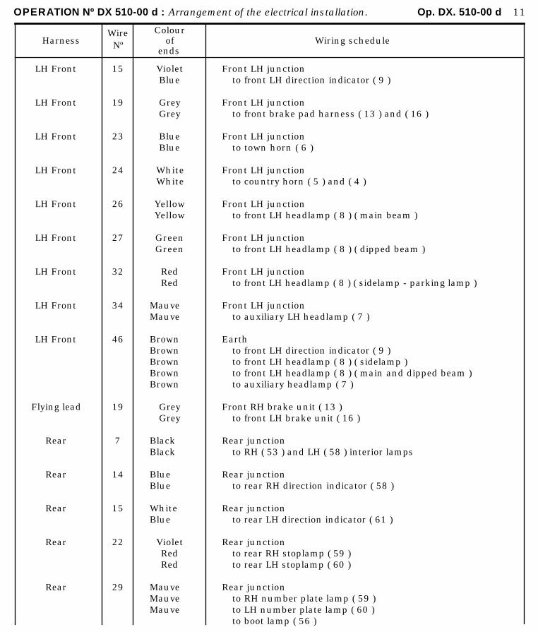
OPERATION Nº DX 510-00 d : Arrangement of the electrical installation. Op. DX. 510-00 d 11
HarnessWireNº
Colourof
endsWiring schedule
LH Front
LH Front
LH Front
LH Front
LH Front
LH Front
LH Front
LH Front
LH Front
Flying lead
Rear
Rear
Rear
Rear
Rear
15
19
23
24
26
27
32
34
46
19
7
14
15
22
29
VioletBlue
GreyGrey
BlueBlue
WhiteWhite
YellowYellow
GreenGreen
RedRed
MauveMauve
BrownBrownBrownBrownBrown
GreyGrey
BlackBlack
BlueBlue
WhiteBlue
VioletRedRed
MauveMauveMauve
Front LH junctionto front LH direction indicator ( 9 )
Front LH junctionto front brake pad harness ( 13 ) and ( 16 )
Front LH junctionto town horn ( 6 )
Front LH junctionto country horn ( 5 ) and ( 4 )
Front LH junctionto front LH headlamp ( 8 ) ( main beam )
Front LH junctionto front LH headlamp ( 8 ) ( dipped beam )
Front LH junctionto front LH headlamp ( 8 ) ( sidelamp - parking lamp )
Front LH junctionto auxiliary LH headlamp ( 7 )
Earthto front LH direction indicator ( 9 )to front LH headlamp ( 8 ) ( sidelamp )to front LH headlamp ( 8 ) ( main and dipped beam )to auxiliary headlamp ( 7 )
Front RH brake unit ( 13 )to front LH brake unit ( 16 )
Rear junctionto RH ( 53 ) and LH ( 58 ) interior lamps
Rear junctionto rear RH direction indicator ( 58 )
Rear junctionto rear LH direction indicator ( 61 )
Rear junctionto rear RH stoplamp ( 59 )to rear LH stoplamp ( 60 )
Rear junctionto RH number plate lamp ( 59 )to LH number plate lamp ( 60 )to boot lamp ( 56 )
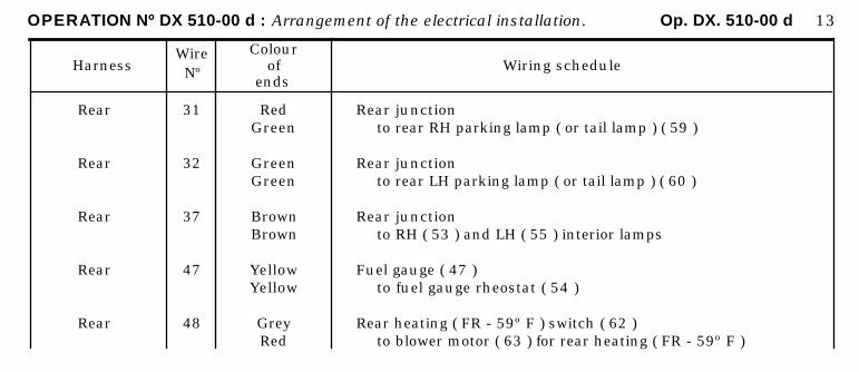
OPERATION Nº DX 510-00 d : Arrangement of the electrical installation. Op. DX. 510-00 d 13
HarnessWireNº
Colourof
endsWiring schedule
Rear
Rear
Rear
Rear
Rear
31
32
37
47
48
RedGreen
GreenGreen
BrownBrown
YellowYellow
GreyRed
Rear junctionto rear RH parking lamp ( or tail lamp ) ( 59 )
Rear junctionto rear LH parking lamp ( or tail lamp ) ( 60 )
Rear junctionto RH ( 53 ) and LH ( 55 ) interior lamps
Fuel gauge ( 47 )to fuel gauge rheostat ( 54 )
Rear heating ( FR - 59º F ) switch ( 62 )to blower motor ( 63 ) for rear heating ( FR - 59º F )
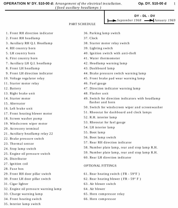
OPERATION N0 DY. 510-00 d: Arrangement of the electrical installation. Op. DY. 510-00 d 1( fixed auxiliary headlamps )
DY - DL - DVSeptember 1968 January 1969
PART SCHEDULE
1. Front RH direction indicator
2. Front RH headlamp
3. Auxiliary RH Q.I. Headlamp
4. RH country horn
5. LH country horn
6. First country horn
7. Auxiliary LH Q.I. headlamp
8. Front LH headlamp
9. Front LH direction indicator
10. Voltage regulator relay
11. Starter motor relay
12. Battery
13. Right brake unit
14. Starter motor
15. Alternator
16. Left brake unit
17. Front heating blower motor
18. Screen washer pump
19. Windscreen wiper motor
20. Accessory terminal
21. Auxiliary headlamp relay 22
22. Brake pressure switch
23. Thermal sensor
24. Stop lamp switch
25. Engine oil pressure switch
26. Distributor
27. Ignition coil
28. Fuse box
29. Front RH door pillar switch
30. Front LH door pillar switch
31. Cigar lighter
32. Engine oil pressure warning lamp
33. Charge warning lamp
34. Front heating switch
35. Interior lamp switch
36. Parking lamp switch
37. Clock
38. Starter motor relay switch
39. Lighting switch
40. Ignition switch with anti-theft
41. Water thermometer
42. Headlamp warning lamp
43. Dashboard lamp
44. Brake pressure switch warning lamp
45. Front brake pad wear warning lamp
46. Fuel gauge
47. Direction indicator warning lamp
48. Flasher unit
49. Switch for direction indicators with headlampflasher and horn
50. Switch for windscreen wiper and screenwasher
51. Rheostat for dashboard and clock lamps
52. R.H. interior lamp
53. Rheostat for fuel gauge
54. LH interior lamp
55. Boot lamp
56. Boot lamp switch
57. Rear RH direction indicator
58. Number plate lamp, rear and stop lamp R.H.
59. Number plate lamp, rear and stop lamp R.H.
60. Rear LH direction indicator
OPTIONAL FITTINGS
61. Rear heating switch ( FR - 59ºF )
62. Rear heating blower ( FR - 59º F )
63. Air blower switch
64. Air blower
65. Horn compressor relay
66. Horn compressor

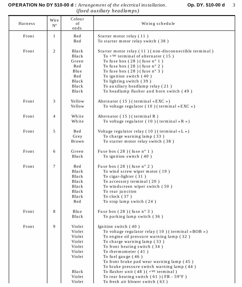
OPERATION No DY 510-00 d : Arrangement of the electrical installation. Op. DY. 510-00 d 3(fixed auxiliary headlamps)
HarnessWireNº
Colourof
endsWiring schedule
Front
Front
Front
Front
Front
Front
Front
Front
Front
1
2
3
4
5
6
7
8
9
RedRed
BlackBlackGreenRedBlueRed
BlackBlackBlack
YellowYellow
WhiteWhite
RedGrey
Brown
GreenBlack
RedBlackBlackBlackBlackBlackBlackRed
BlueBlack
VioletVioletVioletVioletVioletVioletViolet
BlackVioletViolet
Starter motor relay ( 11 )To starter motor relay switch ( 38 )
Starter motor relay ( 11 ) ( non-disconnectible terminal )To +ve terminal of alternator ( 15 )To fuse box ( 28 ) ( fuse nº 1 )To fuse box ( 28 ) ( fuse nº 2 )To fuse box ( 28 ) ( fuse nº 3 )To ignition switch ( 40 )To lighting switch ( 39 )To auxiliary headlamp relay ( 21 )To headlamp flasher and horn switch ( 49 )
Alternator ( 15 ) ( terminal « EXC » )To voltage regulator ( 10 ) ( terminal « EXC » )
Alternator ( 15 ) ( terminal R )To voltage regulator ( 10 ) ( terminal « R » )
Voltage regulator relay ( 10 ) ( terminal « L » )To charge warning lamp ( 33 )To starter motor relay switch ( 38 )
Fuse box ( 28 ) ( fuse nº 1 )To ignition switch ( 40 )
Fuse box ( 28 ) ( fuse nº 2 )To wind screw wiper motor ( 19 )To cigar-lighter ( 31 )To accessory terminal ( 20 )To windscreen wiper switch ( 50 )To rear junctionTo clock ( 37 )To stop lamp switch ( 24 )
Fuse box ( 28 ) ( fuse nº 3 )To parking lamp switch ( 36 )
Ignition switch ( 40 )To voltage regulator relay ( 10 ) ( terminal « BOB » )To engine oil pressure warning lamp ( 32 )To charge warning lamp ( 33 )To front heating switch ( 34 )To thermometer ( 41 )To fuel gauge ( 46 )To front brake pad wear warning lamp ( 45 )To brake pressure switch warning lamp ( 44 )To flasher unit ( 48 ) ( +ve terminal )To rear heating switch ( 61 ) ( FR - 59ºF )To fresh air blower switch ( 63 )

OPERATION No DY 510-00 d : Arrangement of the electrical installation. Op. DY. 510-00 d 5(fixed auxiliary headlamps)
HarnessWireNº
Colourof
endsWiring schedule
Front
Front
Front
Front
Front
Front
Direction indica-tor switch
Front
Front
Front
Front
Front
Front
Front
Front
10
11
12
13
14
15
16
17
18
19
20
21
22
23
24
WhiteWhite
RedRed
BlueBlue
VioletRed
GreenVioletBlue
YellowVioletWhite
Violet
GreenGreen
BrownBrown
GreyGrey
BlueBlue
WhiteRed
VioletViolet
BlueBlue
WhiteWhite
Windscreen wiper switch ( 50 )To windscreen wiper motor ( 19 )
Windscreen wiper switch ( 50 )To windscreen wiper motor ( 19 )
Windscreen wiper switch ( 58 )To windscreen wiper motor ( 19 )
Screen washer switch ( 50 )To screen washer pump ( 18 )
Direction indicator switch ( 49 )To front left wing junctionTo rear junction
Direction indicator switch ( 49 )To front right wing junctionTo rear junction
Flasher unit ( 48 ) ( terminal c )To direction indicator switch ( 49 )
Flasher unit ( 48 ) ( terminal R )To direction indicator warning lamp ( 47 )
Brake pressure switch warning lamp ( 44 )Brake pressure switch ( 22 )
Front brake pad wear warning lamp ( 45 )To front left wing junction
Thermometer ( 41 )To feed wire for thermal sensor ( 23 )
Engine oil pressure warning lamp ( 32 )To feed wire for engine oil pressure switch ( 25 )
Stop lamp switch ( 24 )To rear junction
Horn switch ( 49 )To front left wing junction
Horn switch ( 49 )To front left wing junction.
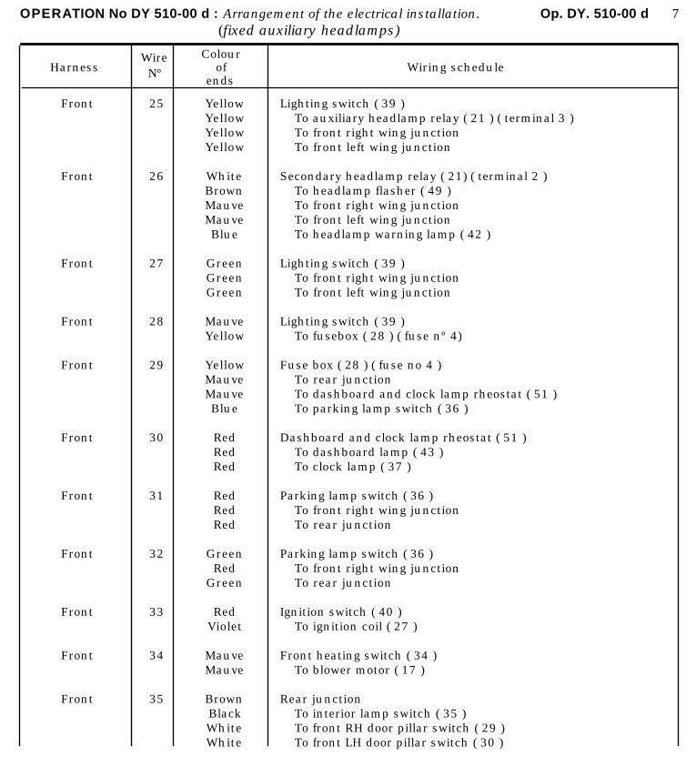
OPERATION No DY 510-00 d : Arrangement of the electrical installation. Op. DY. 510-00 d 7(fixed auxiliary headlamps)
HarnessWireNº
Colourof
endsWiring schedule
Front
Front
Front
Front
Front
Front
Front
Front
Front
Front
Front
25
26
27
28
29
30
31
32
33
34
35
Yellow YellowYellowYellow
WhiteBrownMauveMauveBlue
GreenGreenGreen
MauveYellow
YellowMauveMauveBlue
RedRedRed
RedRedRed
GreenRed
Green
RedViolet
MauveMauve
BrownBlackWhiteWhite
Lighting switch ( 39 )To auxiliary headlamp relay ( 21 ) ( terminal 3 )To front right wing junctionTo front left wing junction
Secondary headlamp relay ( 21) ( terminal 2 )To headlamp flasher ( 49 )To front right wing junctionTo front left wing junctionTo headlamp warning lamp ( 42 )
Lighting switch ( 39 )To front right wing junctionTo front left wing junction
Lighting switch ( 39 )To fusebox ( 28 ) ( fuse nº 4)
Fuse box ( 28 ) ( fuse no 4 )To rear junctionTo dashboard and clock lamp rheostat ( 51 )To parking lamp switch ( 36 )
Dashboard and clock lamp rheostat ( 51 )To dashboard lamp ( 43 )To clock lamp ( 37 )
Parking lamp switch ( 36 )To front right wing junctionTo rear junction
Parking lamp switch ( 36 )To front right wing junctionTo rear junction
Ignition switch ( 40 )To ignition coil ( 27 )
Front heating switch ( 34 )To blower motor ( 17 )
Rear junctionTo interior lamp switch ( 35 )To front RH door pillar switch ( 29 )To front LH door pillar switch ( 30 )
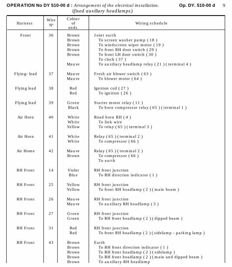
OPERATION No DY 510-00 d : Arrangement of the electrical installation. Op. DY. 510-00 d 9(fixed auxiliary headlamps)
HarnessWireNº
Colourof
endsWiring schedule
Front
Flying- lead
Flying lead
Flying lead
Air Horn
Air Horn
Air Home
RH Front
RH Front
RH Front
RH Front
RH Front
RH Front
36
37
38
39
40
41
42
14
25
26
27
31
43
BrownBrownBrownBrownBrown
Mauve
MauveMauve
RedRed
GreenBlack
WhiteWhiteYellow
WhiteWhite
MauveBrown
VioletBlue
YellowYellow
MauveMauve
GreenGreen
RedRed
BrownBrownBrownBrownBrown
Joint earthTo screen washer pump ( 18 )To windscreen wiper motor ( 19 )To front RH door switch ( 29 )To front LH door switch ( 30 )To clock ( 37 )To auxiliary headlamp relay ( 21 ) ( terminal 4 )
Fresh air blower switch ( 63 )To blower motor ( 64 )
Ignition coil ( 27 )To ignition ( 26 )
Starter motor relay ( 11 )To horn compressor relay ( 65 ) ( terminal 1 )
Road horn RH ( 4 )To link wireTo relay ( 65 ) ( terminal 3 )
Relay ( 65 ) ( terminal 2 )To compressor ( 66 )
Relay ( 65 ) ( terminal 2 )To compressor ( 66 )To earth
RH front junctionTo RH direction indicator ( 1 )
RH front junctionTo front RH headlamp ( 2 ) ( main beam )
RH front junctionTo auxiliary RH headlamp ( 3 )
RH front junctionTo RH front headlamp ( 2 ) ( dipped beam )
RH front junctionTo front RH headlamp ( 2 ) ( sidelamp - parking lamp )
EarthTo RH front direction indicator ( 1 )To RH front headlamp ( 2 ) ( sidelamp )To RH front headlamp ( 2 ) ( main and dipped beam )To auxiliary RH headlamp
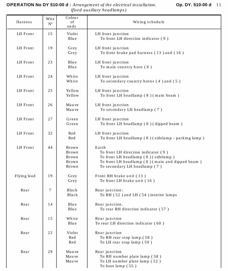
OPERATION No DY 510-00 d : Arrangement of the electrical installation. Op. DY. 510-00 d 11(fixed auxiliary headlamps)
HarnessWireNº
Colourof
endsWiring schedule
LH Front
LH Front
LH Front
LH Front
LH Front
LH Front
LH Front
LH Front
LH Front
Flying lead
Rear
Rear
Rear
Rear
Rear
15
19
23
24
25
26
27
32
44
19
7
14
15
22
29
VioletBlue
GreyGrey
BlueBlue
WhiteWhite
YellowYellow
MauveMauve
GreenGreen
RedRed
BrownBrownBrownBrownBrown
GreyGrey
BlackBlack
BlueBlue
WhiteBlue
VioletRedRed
MauveMauveMauve
LH front junctionTo front LH direction indicator ( 9 )
LH front junctionTo front brake pad harness ( 13 ) and ( 16 )
LH front junctionTo main country horn ( 6 )
LH front junctionTo secondary country horns ( 4 ) and ( 5 )
LH front junctionTo front LH headlamp ( 8 ) ( main beam )
LH front junctionTo secondary LH headlamp ( 7 )
LH front junctionTo front LH headlamp ( 8 ) ( dipped beam )
LH front junctionTo front LH headlamp ( 8 ) ( sidelamp - parking lamp )
EarthTo front LH direction indicator ( 9 )To front LH headlamp ( 8 ) ( sidelamp )To front LH headlamp ( 8 ) ( main and dipped beam )To secondary LH headlamp ( 7 )
Front RH brake unit ( 13 )To front LH brake unit ( 16 )
Rear junction:To RH ( 52 ) and LH ( 54 ) interior lamps
Rear junction.To rear RH direction indicator ( 57 )
Rear junctionTo rear LH direction indicator ( 60 )
Rear junctionTo RH rear stop lamp.( 58 )To LH rear stop lamp ( 59 )
Rear junctionTo RH number plate lamp ( 58 )To LH number plate lamp ( 52 )To boot lamp ( 55 )
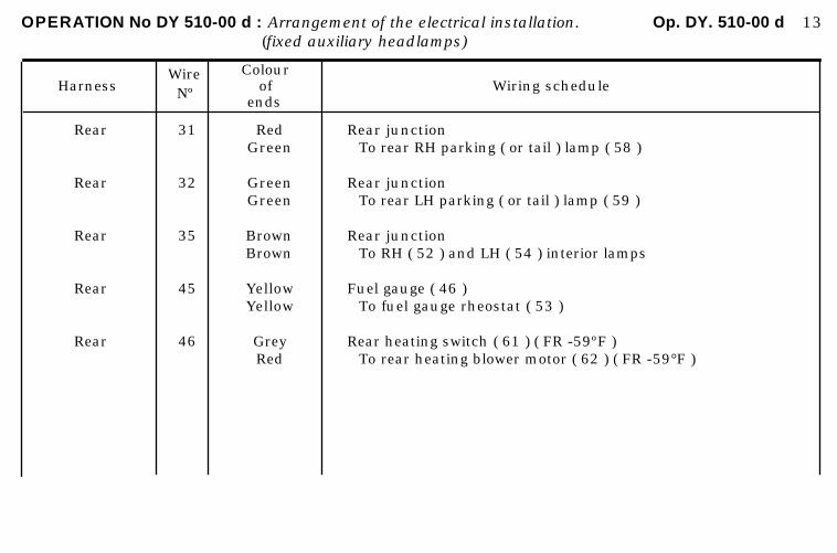
OPERATION No DY 510-00 d : Arrangement of the electrical installation. Op. DY. 510-00 d 13(fixed auxiliary headlamps)
HarnessWireNº
Colourof
endsWiring schedule
Rear
Rear
Rear
Rear
Rear
31
32
35
45
46
RedGreen
GreenGreen
BrownBrown
YellowYellow
GreyRed
Rear junctionTo rear RH parking ( or tail ) lamp ( 58 )
Rear junctionTo rear LH parking ( or tail ) lamp ( 59 )
Rear junctionTo RH ( 52 ) and LH ( 54 ) interior lamps
Fuel gauge ( 46 )To fuel gauge rheostat ( 53 )
Rear heating switch ( 61 ) ( FR -59ºF )To rear heating blower motor ( 62 ) ( FR -59°F )
OPERATION N’ DX. 510.00 e : Arrangement of the electrical installation Op. DX, 510-00 e i (0.1. auxiliarr headlamps)
DX - DJ
h Jan 1969 +.Sept 1969
ARRANGEMENT OF THE ELECTRLCAL INSTALLATION
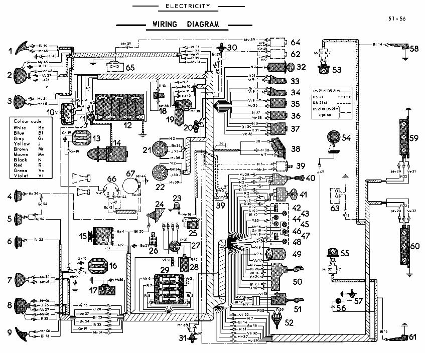
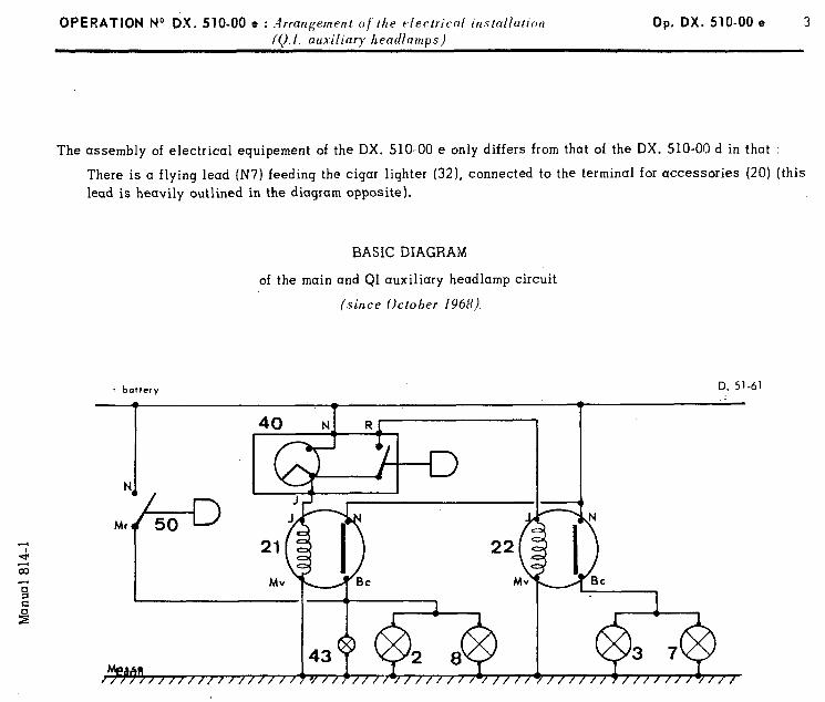
OPERATION No DX. 510-00 e : .4 rrangement of the electrical installation 10.1. auxiliarr hearllamus)
Op. DX. 510-00 e 3
The assembly of electrical equipement of the DX. 510-00 e only differs from that of the DX. 510-00 d in that :
There is a flying lead (N7) feeding the cigar lighter (32), connected to the terminal for accessories (20) (this lead is heavily outlined in the diagram opposite).
BASIC DIAGRAM
of the main and QI auxiliary headlamp circuit
(since October 1968).
i battery
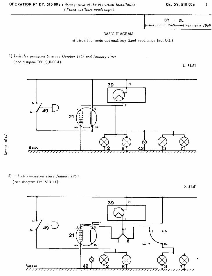
OPERATION No DY. 510-OOe : irrangement o/the electrical installation Op. DY. 510-OOe 1 ( Fixed auxiliary headlamps ).
DY - DL ~~ilrrrrc~r.~ /01,9*~Sc~l~tenrber 1969
6
BASIC DIAGRAM
of circuit for main andauxiliary fixed headlamps (not 0.1.)
l)I,‘l’l , d e UC es )ro uct*d between October 1968 and /anldary 1969
( see diagram DY. 510-00 d ). D. 51-61
2) 1 cshic/c, l)rodu1.vd sincr ./anrrcq 1969.
( see diagram DY. 510-l f’). D. 51-61

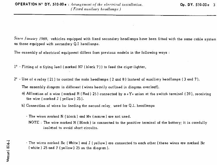
OPERATION No DY. 510-OOe : Arrangement of the electrical installation. Op. DY. 510-OOe 3 (Fixed auxiliary headlamps )
Since January 1969, vehicles equipped with fixed secondary headlamps have been fitted with the same cable system
as those equipped with secondary Q.1 headlamps.
The assembly of electrical equipment differs from previous models in the following ways :
lo - Fitting of a flying leai ( marked N7 ( black 7 ) ) to feed the cigar-lighter.
2” - Use of a relay (21 ) to control the main headlamps ( 2 and 8) instead of auxiliary headlamps ( 3 and 7).
The assembly diagram is different (wires heavily outlined in diagram overleaf).
a) Affixation of a wire ( marked R ( Red ) 25 ) connected by a ((Y)) union at the switch terminal ( 39 ), receiving
the wire ( marked J ( yellow ) 25 ).
b) Connection of wires for feeding the second relay, used for Q.I. headlamps
- The wires marked N ( black ) and Mv (mauve) are not used.
NOTE : The wire marked N ( Black) is connected to the positive terminal of the battery; it is carefully
isolated to avoid short circuits.
- The wires marked Bc ( White ) and J ( yellow ) are connected to each other (these wires are marked Bc
( white ) 25 and J ( yellow) 25 on the diagram ).
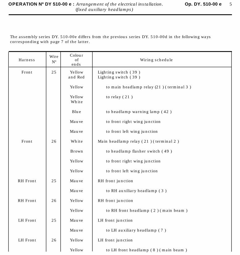
OPERATION Nº DY 510-00 e : Arrangement of the electrical installation. Op. DY. 510-00 e 5(fixed auxiliary headlamps)
The assembly series DY. 510-00e differs from the previous series DY. 510-00d in the following ways corresponding with page 7 of the latter.
HarnessWireNº
Colourof
endsWiring schedule
Front
Front
RH Front
RH Front
LH Front
LH Front
25
26
25
26
25
26
Yellowand Red
Yellow
YellowWhite
Blue
Mauve
Mauve
White
Brown
Yellow
Yellow
Mauve
Mauve
Yellow
Yellow
Mauve
Mauve
Yellow
Yellow
Lighting switch ( 39 )Lighting switch ( 39 )
to main headlamp relay (21 ) ( terminal 3 )
to relay ( 21 )
to headlamp warning lamp ( 42 )
to front right wing junction
to front left wing junction
Main headlamp relay ( 21 ) ( terminal 2 )
to headlamp flasher switch ( 49 )
to front right wing junction
to front left wing junction
RH front junction
to RH auxiliary headlamp ( 3 )
RH front junction
to RH front headlamp ( 2 ) ( main beam )
LH front junction
to LH auxiliary headlamp ( 7 )
LH front junction
to LH front headlamp ( 8 ) ( main beam )
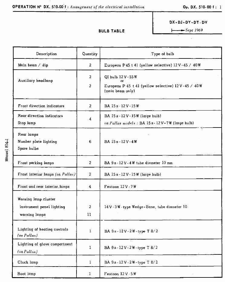
OPERATION No DX. 510.00 f : Arrangement of the electrical installation
BULB TABLE
Op. DX. 510-00 f : 1
DX=DJ=DY=DT-DV
I--Sept 1969
Description
Main beam / dip
Auxiliary headlamp
Quantity Type of bulb
2 European P45 t 41 (yellow selective) 12 V-45 / 40W
2 QI bulb 12V-55W or
2 European P 45 t 41 (yellow selective) 12 V-45 / 40 W (main beam only)
Front direction indicators
Rear direction indicators
Stop lamp
Bear lamps
Number plate lighting
Spare bulbs
2 BA 15s-12V-15W
4 BA 15s-12V-15W (large bulb)
on Pallas models : BA 15 s- 12 V-7 W (large bulb) -i-
6 BA i5s-12V-4W
Front parking lamps 2 BA 9s-12V-4W tube diameter 10 mm
Front interior lamps (oh Pallas) 2 BA 15s-12V-15W (large bulb)
Front and rear interior, lamps 4 Festoon 12 V - 7 W
Warning lamp cluster
instrument panel lighting 2 14 V - 3 W -type Wedge- Base, tube diameter 10
warning lamps 11 --
Lighting of heating controls
(on Pallas) 1 BA 9s-12V-2W-type T 8/2
Lighting of glove compartment
(on Pallas) 1 BA 9s- 12V-2W-type T 8/2
Clock lamp 1 BA 9s-12V-2W-type T 8/2
Boot lamp 1 Festoon 12V-5W
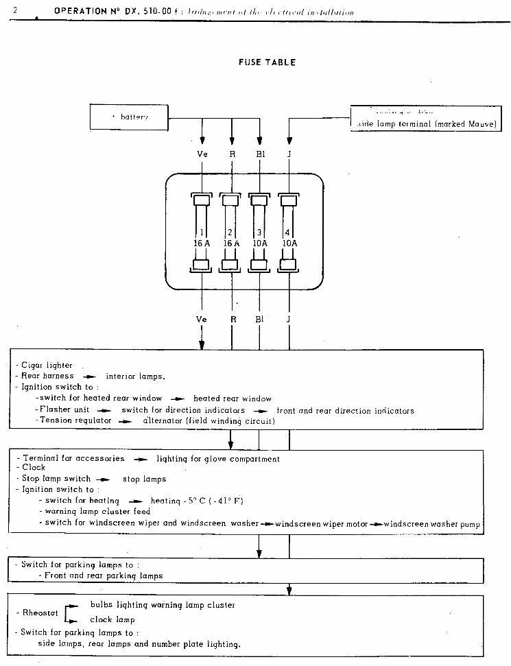
FUSE TABLE
.;ide lamp terminal (marked Mauve)
Ve R Bl J Ve R Bl J
~ 1 2 3 4 16A 16A 10A 16A 16A 10A 10A 10A
i Ve R Bl J
- Cigar lighter - Rear harness t interior lamps.
- Ignition switch to : -switch for heated rear window --t heated rear window -Flasher unit -F switch for direction indicators - front and rear direction indicators -Tension regulator -t alternator (field winding circuit)
- Terminal for accessories --t lighting for glove compartment - Clock - Stop lamp switch --t stop lamps - Ignition switch to :
- switch for heating - heating -5’ C (-41’F) - warning lamp cluster feed
- switch for windscreen wiper and windscreen washer-windscreen wiper motor -windscreen washer pump
- Switch for parking lamps to : - Front and rear parking lamps
- Rheostat CT
bulbs lighting warning lamp cluster
clock lamp
- Switch for parking lamps to :
side lamps, rear lamps and number plate lighting,
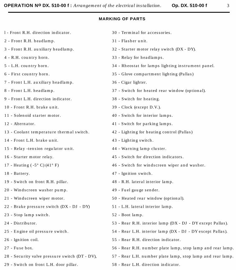
OPERATION No DX. 510-00 f : Arrangement of the electrical installation. Op. DX. 510-00 f 3
MARKING OF PARTS
l - Front R.H. direction indicator.
2 - Front R.H. headlamp.
3 - Front R.H. auxiliary headlamp.
4 - R.H. country horn.
5 - L.H. country horn.
6 - First country horn.
7 - Front L.H. auxiliary headlamp.
8 - Front L.H. headlamp.
9 - Front L.H. direction indicator.
10 - Front R.H. brake unit.
11 - Solenoid starter motor.
12 - Alternator.
13 - Coolant temperature thermal switch.
14 - Front L.H. brake unit.
15 - Relay -tension regulator unit.
16 - Starter motor relay.
17 - Heating ( -5º C) (41º F)
18 - Battery.
19 - Switch on front R.H. pillar.
20 - Windscreen washer pump.
21 - Windscreen wiper motor.
22 - Brake pressure switch (DX - DJ - DY)
23 - Stop lamp switch.
24 - Distributor.
25 - Engine oil pressure switch.
26 - Ignition coil.
27 - Fuse box.
28 - Security valve pressure switch (DT - DV),
29 - Switch on front L.H. door pillar.
30 - Terminal for accessories.
31 - Flasher unit.
32 - Starter motor relay switch (DX - DY).
33 - Relay for headlamps.
34 - Rheostat for lamps lighting instrument panel.
35 - Glove compartment lighting (Pallas)
36 - Cigar lighter.
37 - Switch for heated rear window (optional).
38 - Switch for heating.
39 - Clock (except D.V.).
40 - Switch for interior lamps.
41 - Switch for parking lamps.
42 - Lighting for heating control (Pallas)
43 - Lighting switch.
44 - Warning lamp cluster.
45 - Switch for direction indicators.
46 - Switch for windscreen wiper and washer.
47 - Ignition switch.
48 - R.H. lateral interior lamp.
49 - Fuel gauge sender.
50 - Heated rear window (optional).
51 - L.H. lateral interior lamp.
52 - Boot lamp.
53 - Rear R.H. interior lamp (DX - DJ - DY except Pallas).
54 - Rear L.H. interior lamp (DX - DJ - DY except Pallas).
55 - Rear R.H. direction indicator.
56 - Rear R.H. number plate lamp, stop lamp and rear lamp.
57 - Rear L.H. number plate lamp, stop lamp and rear lamp.
58 - Rear L.H. direction indicator.
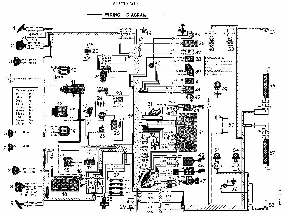
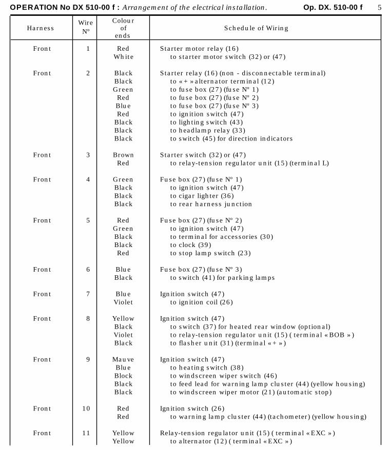
OPERATION No DX 510-00 f : Arrangement of the electrical installation. Op. DX. 510-00 f 5
HarnessWireNº
Colourof
endsSchedule of Wiring
Front
Front
Front
Front
Front
Front
Front
Front
Front
Front
Front
1
2
3
4
5
6
7
8
9
10
11
RedWhite
BlackBlackGreenRedBlueRed
BlackBlackBlack
BrownRed
GreenBlackBlackBlack
RedGreenBlackBlackRed
BlueBlack
BlueViolet
YellowBlackVioletBlack
MauveBlueBlockBlackBlack
RedRed
YellowYellow
Starter motor relay (16)to starter motor switch (32) or (47)
Starter relay (16) (non - disconnectable terminal)to « + » alternator terminal (12)to fuse box (27) (fuse Nº 1)to fuse box (27) (fuse Nº 2)to fuse box (27) (fuse Nº 3)to ignition switch (47)to lighting switch (43)to headlamp relay (33)to switch (45) for direction indicators
Starter switch (32) or (47)to relay-tension regulator unit (15) (terminal L)
Fuse box (27) (fuse Nº 1)to ignition switch (47)to cigar lighter (36)to rear harness junction
Fuse box (27) (fuse Nº 2)to ignition switch (47)to terminal for accessories (30)to clock (39)to stop lamp switch (23)
Fuse box (27) (fuse Nº 3)to switch (41) for parking lamps
Ignition switch (47)to ignition coil (26)
Ignition switch (47)to switch (37) for heated rear window (optional)to relay-tension regulator unit (15) ( terminal « BOB » )to flasher unit (31) (terminal « + » )
Ignition switch (47)to heating switch (38)to windscreen wiper switch (46)to feed lead for warning lamp cluster (44) (yellow housing)to windscreen wiper motor (21) (automatic stop)
Ignition switch (26)to warning lamp cluster (44) (tachometer) (yellow housing)
Relay-tension regulator unit (15) ( terminal « EXC » )to alternator (12) ( terminal « EXC » )
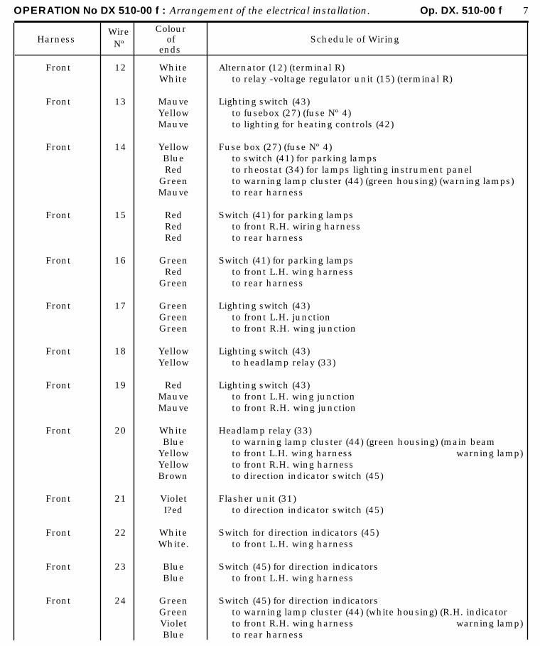
OPERATION No DX 510-00 f : Arrangement of the electrical installation. Op. DX. 510-00 f 7
HarnessWireNº
Colourof
endsSchedule of Wiring
Front
Front
Front
Front
Front
Front
Front
Front
Front
Front
Front
Front
Front
12
13
14
15
16
17
18
19
20
21
22
23
24
WhiteWhite
MauveYellowMauve
YellowBlueRed
GreenMauve
RedRedRed
GreenRed
Green
GreenGreenGreen
YellowYellow
RedMauveMauve
WhiteBlue
YellowYellowBrown
VioletI?ed
WhiteWhite.
BlueBlue
GreenGreenVioletBlue
Alternator (12) (terminal R)to relay -voltage regulator unit (15) (terminal R)
Lighting switch (43)to fusebox (27) (fuse Nº 4)to lighting for heating controls (42)
Fuse box (27) (fuse Nº 4)to switch (41) for parking lampsto rheostat (34) for lamps lighting instrument panelto warning lamp cluster (44) (green housing) (warning lamps)to rear harness
Switch (41) for parking lampsto front R.H. wiring harnessto rear harness
Switch (41) for parking lampsto front L.H. wing harnessto rear harness
Lighting switch (43)to front L.H. junctionto front R.H. wing junction
Lighting switch (43)to headlamp relay (33)
Lighting switch (43)to front L.H. wing junctionto front R.H. wing junction
Headlamp relay (33)to warning lamp cluster (44) (green housing) (main beamto front L.H. wing harness warning lamp)to front R.H. wing harnessto direction indicator switch (45)
Flasher unit (31)to direction indicator switch (45)
Switch for direction indicators (45)to front L.H. wing harness
Switch (45) for direction indicatorsto front L.H. wing harness
Switch (45) for direction indicatorsto warning lamp cluster (44) (white housing) (R.H. indicatorto front R.H. wing harness warning lamp)to rear harness
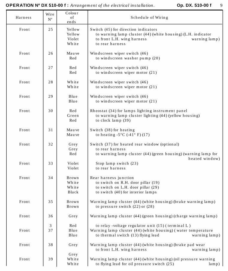
OPERATION Nº DX 510-00 f : Arrangement of the electrical installation. Op. DX. 510-00 f 9
HarnessWireNº
Colourof
endsSchedule of Wiring
Front
Front
Front
Front
Front
Front
Front
Front
Front
Front
Front
Front
Front
Front
Front
25
26
27
28
29
30
31
32
33
34
35
36
337
38
39
YellowYellowVioletWhite
MauveRed
RedRed
WhiteWhite
BlueBlue
RedGreenRed
MauveMauve
GreyGreyRed
VioletViolet
BrownWhiteWhiteBlack
BrownBrown
Grey
RedBlueBlue
Grey
GreyWhiteWhite
Switch (45) for direction indicatorsto warning lamp cluster (44) (white housing) (L.H. indicator to front L.H. wing harness warning lamp)to rear harness
Windscreen wiper switch (46)to windscreen washer pump (20)
Windscreen wiper switch (46)to windscreen wiper motor (21)
Windscreen wiper switch (46)to windscreen wiper motor (21)
Windscreen wiper switch (46)to windscreen wiper motor (21)
Rheostat (34) for lamps lighting instrument panelto warning lamp cluster lighting (44) (yellow housing)to clock lamp (39)
Switch (38) for heatingto heating -5ºC (-41º F) (17)
Switch (37) for heated rear window (optional)to rear harnessto warning lamp cluster (44) (green housing) (warning lamp for
heated window)Stop lamp switch (23)to rear harness
Rear harness junctionto switch on R.H. door pillar (19)to switch on L.H. door pillar (29)to switch (40) for interior lamps
Warning lamp cluster (44) (white housing) (brake warning lamp)to pressure switch (22) or (28)
Warning lamp cluster (44) (green housing) (charge warning lamp)
to relay -voltage regulator unit (15) ( terminal L )Warning lamp cluster (44) (white housing) ( water temperature
to thermal switch (13) flying lead warning lamp)
Warning lamp cluster (44) (white housing) (brake pad wearto front L.H. wing harness warning lamp)
Warning lamp cluster (44) (white housing) (oil pressure warning to flying lead for oil pressure switch (25) lamp)
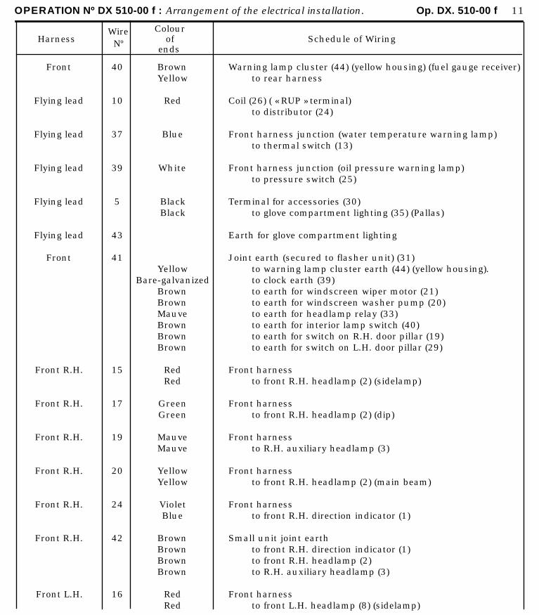
OPERATION Nº DX 510-00 f : Arrangement of the electrical installation. Op. DX. 510-00 f 11
HarnessWireNº
Colourof
endsSchedule of Wiring
Front
Flying lead
Flying lead
Flying lead
Flying lead
Flying lead
Front
Front R.H.
Front R.H.
Front R.H.
Front R.H.
Front R.H.
Front R.H.
Front L.H.
40
10
37
39
5
43
41
15
17
19
20
24
42
16
BrownYellow
Red
Blue
White
BlackBlack
YellowBare-galvanized
BrownBrownMauveBrownBrownBrown
RedRed
GreenGreen
MauveMauve
YellowYellow
VioletBlue
BrownBrownBrownBrown
RedRed
Warning lamp cluster (44) (yellow housing) (fuel gauge receiver)to rear harness
Coil (26) ( « RUP » terminal)to distributor (24)
Front harness junction (water temperature warning lamp)to thermal switch (13)
Front harness junction (oil pressure warning lamp)to pressure switch (25)
Terminal for accessories (30)to glove compartment lighting (35) (Pallas)
Earth for glove compartment lighting
Joint earth (secured to flasher unit) (31)to warning lamp cluster earth (44) (yellow housing).to clock earth (39)to earth for windscreen wiper motor (21)to earth for windscreen washer pump (20)to earth for headlamp relay (33)to earth for interior lamp switch (40)to earth for switch on R.H. door pillar (19)to earth for switch on L.H. door pillar (29)
Front harnessto front R.H. headlamp (2) (sidelamp)
Front harnessto front R.H. headlamp (2) (dip)
Front harnessto R.H. auxiliary headlamp (3)
Front harnessto front R.H. headlamp (2) (main beam)
Front harnessto front R.H. direction indicator (1)
Small unit joint earthto front R.H. direction indicator (1)to front R.H. headlamp (2)to R.H. auxiliary headlamp (3)
Front harnessto front L.H. headlamp (8) (sidelamp)
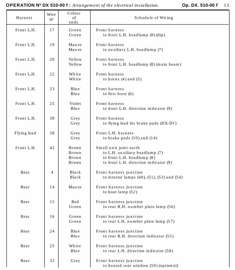
OPERATION Nº DX 510-00 f : Arrangement of the electrical installation. Op. DX. 510-00 f 13
HarnessWireNº
Colourof
endsSchedule of Wiring
Front L.H.
Front L.H.
Front L.H.
Front L;H.
Front L.H.
Front L.H.
Front L.H.
Flying lead
Front L.H.
Rear
Rear
Rear
Rear
Rear
Rear
Rear
17
19
20
22
23
25
38
38
42
4
14
15
16
24
25
32
GreenGreen
MauveMauve
YellowYellow
WhiteWhite
BlueBlue
VioletBlue
GreyGrey
GreyGrey
BrownBrownBrownBrown
BlackBlack
Mauve
RedGreen
GreenGreen
BlueBlue
WhiteBlue
Grey
Front harnessto front L.H. headlamp (8) (dip)
Front harnessto auxiliary L.H. headlamp (7)
Front harnessto front L.H. headlamp (8) (main beam)
Front harnessto horns (4) and (5)
Front harnessto first horn (6)
Front harnessto front L.H. direction indicator (9)
Front harnessto flying lead for brake pads (DX-DJ)
Front L.H. harnessto brake pads (10) and (14)
Small unit joint earthto L.H. auxiliary headlamp (7)to front L.H. headlamp (8)to front L.H. direction indicator (9)
Front harness junctionto interior lamps (48), (51), (53) and (54)
Front harness junctionto boot lamp (52)
Front harness junctionto rear R.H. number plate lamp (56)
Front harness junctionto rear L.H. number plate lamp (57)
Front harness junctionto rear R.H. direction indicator (55)
Front harness junctionto rear L.H. direction indicator (58)
Front harness junctionto heated rear window (50) (optional)
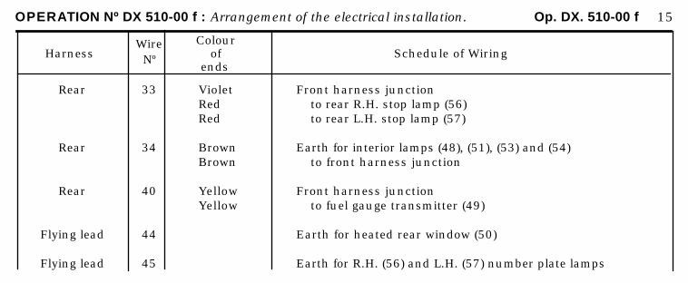
OPERATION Nº DX 510-00 f : Arrangement of the electrical installation. Op. DX. 510-00 f 15
HarnessWireNº
Colourof
endsSchedule of Wiring
Rear
Rear
Rear
Flying lead
Flying lead
33
34
40
44
45
VioletRedRed
BrownBrown
YellowYellow
Front harness junctionto rear R.H. stop lamp (56)to rear L.H. stop lamp (57)
Earth for interior lamps (48), (51), (53) and (54)to front harness junction
Front harness junctionto fuel gauge transmitter (49)
Earth for heated rear window (50)
Earth for R.H. (56) and L.H. (57) number plate lamps
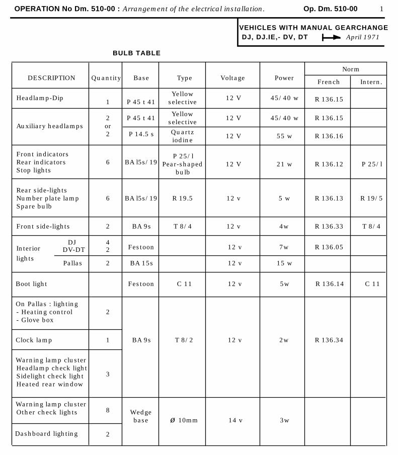
OPERATION No Dm. 510-00 : Arrangement of the electrical installation. Op. Dm. 510-00 1
VEHICLES WITH MANUAL GEARCHANGEDJ, DJ.IE,- DV, DT April 1971
BULB TABLE
NormDESCRIPTION
Headlamp-Dip
Auxiliary headlamps
Front indicatorsRear indicatorsStop lights
Rear side-lightsNumber plate lampSpare bulb
Front side-lights
Quantity
1
2or2
6
6
2
Base
P 45 t 41
P 45 t 41
P 14.5 s
BA l5s/19
BA l5s/19
BA 9s
Type
Yellowselective
Yellow selective
Quartz iodine
P 25/lPear-shaped
bulb
R 19.5
T 8/4
Voltage
12 V
12 V
12 V
12 V
12 v
12 v
Power
45/40 w
45/40 w
55 w
21 w
5 w
4w
French
R 136.15
R 136.15
R 136.16
R 136.12
R 136.13
R 136.33
Intern.
P 25/l
R 19/5
T 8/4
Interior
lights
DJ DV-DT
Pallas
42
2
Festoon
BA 15s
12 v
12 v
7w
15 w
R 136.05
Boot light
On Pallas : lighting- Heating control- Glove box
Clock lamp
Warning lamp clusterHeadlamp check lightSidelight check lightHeated rear window
Warning lamp clusterOther check lights
Dashboard lighting
2
1
3
8
2
Festoon
BA 9s
Wedge base
C 11
T 8/2
ø 10mm
12 v
12 v
14 v
5w
2w
3w
R 136.14
R 136.34
C 11
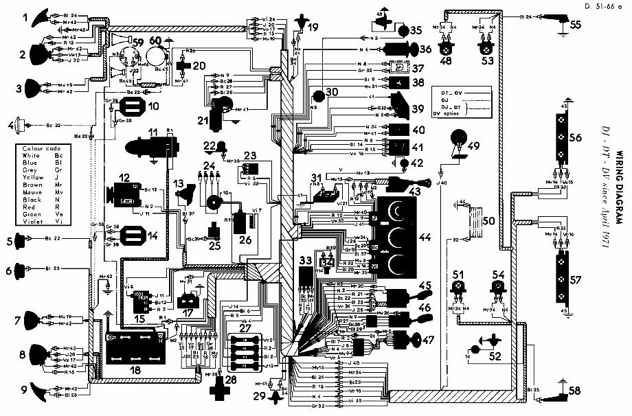

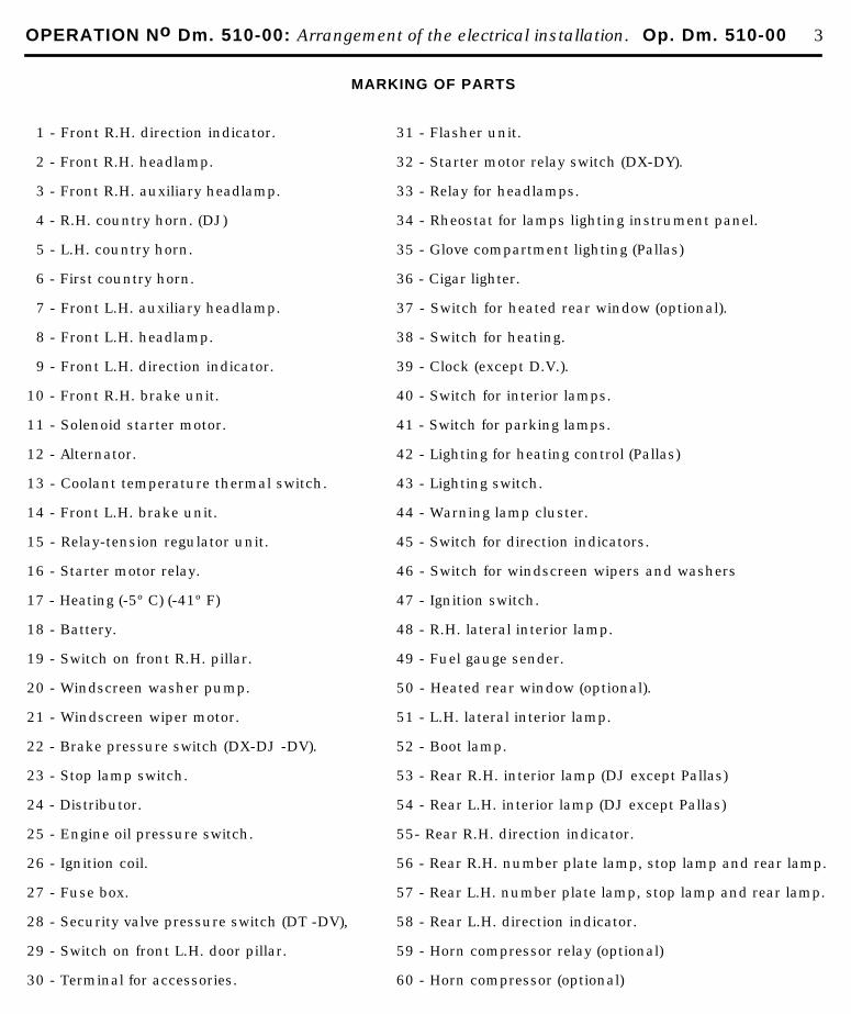
OPERATION No Dm. 510-00: Arrangement of the electrical installation. Op. Dm. 510-00 3
MARKING OF PARTS
1 - Front R.H. direction indicator.
2 - Front R.H. headlamp.
3 - Front R.H. auxiliary headlamp.
4 - R.H. country horn. (DJ)
5 - L.H. country horn.
6 - First country horn.
7 - Front L.H. auxiliary headlamp.
8 - Front L.H. headlamp.
9 - Front L.H. direction indicator.
10 - Front R.H. brake unit.
11 - Solenoid starter motor.
12 - Alternator.
13 - Coolant temperature thermal switch.
14 - Front L.H. brake unit.
15 - Relay-tension regulator unit.
16 - Starter motor relay.
17 - Heating (-5º C) (-41º F)
18 - Battery.
19 - Switch on front R.H. pillar.
20 - Windscreen washer pump.
21 - Windscreen wiper motor.
22 - Brake pressure switch (DX-DJ -DV).
23 - Stop lamp switch.
24 - Distributor.
25 - Engine oil pressure switch.
26 - Ignition coil.
27 - Fuse box.
28 - Security valve pressure switch (DT -DV),
29 - Switch on front L.H. door pillar.
30 - Terminal for accessories.
31 - Flasher unit.
32 - Starter motor relay switch (DX-DY).
33 - Relay for headlamps.
34 - Rheostat for lamps lighting instrument panel.
35 - Glove compartment lighting (Pallas)
36 - Cigar lighter.
37 - Switch for heated rear window (optional).
38 - Switch for heating.
39 - Clock (except D.V.).
40 - Switch for interior lamps.
41 - Switch for parking lamps.
42 - Lighting for heating control (Pallas)
43 - Lighting switch.
44 - Warning lamp cluster.
45 - Switch for direction indicators.
46 - Switch for windscreen wipers and washers
47 - Ignition switch.
48 - R.H. lateral interior lamp.
49 - Fuel gauge sender.
50 - Heated rear window (optional).
51 - L.H. lateral interior lamp.
52 - Boot lamp.
53 - Rear R.H. interior lamp (DJ except Pallas)
54 - Rear L.H. interior lamp (DJ except Pallas)
55- Rear R.H. direction indicator.
56 - Rear R.H. number plate lamp, stop lamp and rear lamp.
57 - Rear L.H. number plate lamp, stop lamp and rear lamp.
58 - Rear L.H. direction indicator.
59 - Horn compressor relay (optional)
60 - Horn compressor (optional)
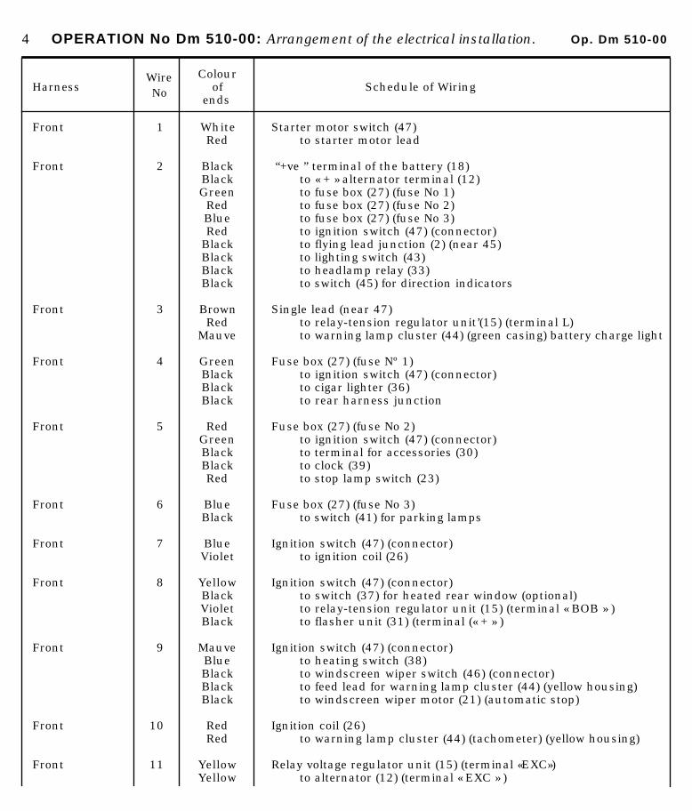
4 OPERATION No Dm 510-00: Arrangement of the electrical installation. Op. Dm 510-00
HarnessWire No
Colourof
ends Schedule of Wiring
Front 1 White Starter motor switch (47)Red to starter motor lead
Front 2 Black “+ve ” terminal of the battery (18)Black to « + » alternator terminal (12)Green to fuse box (27) (fuse No 1)Red to fuse box (27) (fuse No 2)Blue to fuse box (27) (fuse No 3)Red to ignition switch (47) (connector)
Black to flying lead junction (2) (near 45)Black to lighting switch (43)Black to headlamp relay (33)Black to switch (45) for direction indicators
Front 3 Brown Single lead (near 47)Red to relay-tension regulator unit’(15) (terminal L)
Mauve to warning lamp cluster (44) (green casing) battery charge light
Front 4 Green Fuse box (27) (fuse Nº 1)Black to ignition switch (47) (connector)Black to cigar lighter (36)Black to rear harness junction
Front 5 Red Fuse box (27) (fuse No 2)Green to ignition switch (47) (connector)Black to terminal for accessories (30)Black to clock (39)Red to stop lamp switch (23)
Front 6 Blue Fuse box (27) (fuse No 3)Black to switch (41) for parking lamps
Front 7 Blue Ignition switch (47) (connector)Violet to ignition coil (26)
Front 8 Yellow Ignition switch (47) (connector)Black to switch (37) for heated rear window (optional)Violet to relay-tension regulator unit (15) (terminal « BOB » )Black to flasher unit (31) (terminal (« + » )
Front 9 Mauve Ignition switch (47) (connector)Blue to heating switch (38)Black to windscreen wiper switch (46) (connector)Black to feed lead for warning lamp cluster (44) (yellow housing)Black to windscreen wiper motor (21) (automatic stop)
Front 10 Red Ignition coil (26)Red to warning lamp cluster (44) (tachometer) (yellow housing)
Front 11 Yellow Relay voltage regulator unit (15) (terminal «EXC»)Yellow to alternator (12) (terminal « EXC » )
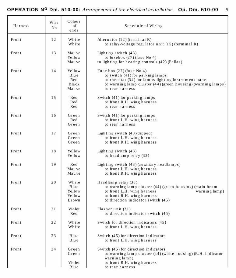
OPERATION No Dm. 510-00: Arrangement of the electrical installation. Op. Dm. 510-00 5
HarnessWire No
Colourof
ends Schedule of Wiring
Front 12 White Alternator (12) (terminal R)White to relay-voltage regulator unit (15) (terminal R)
Front 13 Mauve Lighting switch (43)Yellow to fusebox (27) (fuse No 4)Mauve to lighting for heating controls (42) (Pallas)
Front 14 Yellow Fuse box (27) (fuse No 4)Blue to switch (41) for parking lampsRed to rheostat (34) for lamps lighting instrument panel
Black to warning lamp cluster (44) (green housing) (warning lamps)Mauve to rear harness
Front 15 Red Switch (41) for parking lampsRed to front R.H. wing harnessRed to rear harness
Front 16 Green Switch (41) for parking lampsRed to front L.H. wing harness
Green to rear harness
Front 17 Green Lighting switch (43)(dipped)Green to front L.H. wing harnessGreen to front R.H. wing harness
Front 18 Yellow Lighting switch (43)Yellow to headlamp relay (33)
Front 19 Red Lighting switch (43) (auxiliary headlamps)Mauve to front L.H. wing harnessMauve to front R.H. wing harness
Front 20 White Headlamp relay (33)Blue to warning lamp cluster (44) (green housing) (main beam
Yellow to front L.H. wing harness warning lamp)Yellow to front R.H. wing harnessBrown to direction indicator switch (45)
Front 21 Violet Flasher unit (31)Red to direction indicator switch (45)
Front 22 White Switch for direction indicators (45)White to front L.H. wing harness
Front 23 Blue Switch (45) for direction indicatorsBlue to front L.H. wing harness
Front 24 Green Switch (45) for direction indicatorsGreen to warning lamp cluster (44) (white housing) (R.H. indicator
warning lamp)Violet to front R.H. wing harnessBlue to rear harness
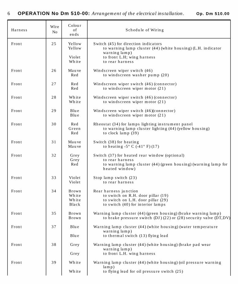
6 OPERATION No Dm 510-00: Arrangement of the electrical installation. Op. Dm 510.00
HarnessWire No
Colourof
ends Schedule of Wiring
Front 25 Yellow Switch (45) for direction indicatorsYellow to warning lamp cluster (44) (white housing) (L.H. indicator
warning lamp)Violet to front L.H; wing harnessWhite to rear harness
Front 26 Mauve Windscreen wiper switch (46)Red to windscreen washer pump (20)
Front 27 Red Windscreen wiper switch (46) (connector)Red to windscreen wiper motor (21)
Front 28 White Windscreen wiper switch (46) (connector)White to windscreen wiper motor (21)
Front 29 Blue Windscreen wiper switch (46)(connector)Blue to windscreen wiper motor (21)
Front 30 Red Rheostat (34) for lamps lighting instrument panelGreen to warning lamp cluster lighting (44) (yellow housing)Red to clock lamp (39)
Front 31 Mauve Switch (38) for heatingMauve to heating -5º C (-41º F) (17)
Front 32 Grey Switch (37) for heated rear window (optional)Grey to rear harnessRed to warning lamp cluster (44) (green housing) (warning lamp for
heated window)
Front 33 Violet Stop lamp switch (23)Violet to rear harness
Front 34 Brown Rear harness junctionWhite to switch on R.H. door pillar (19)White to switch on L.H. door pillar (29)Black to switch (40) for interior lamps
Front 35 Brown Warning lamp cluster (44) (green housing) (brake warning lamp)Brown to brake pressure switch (DJ) (22) or (28) security valve (DT,DV)
Front 37 Blue Warning lamp cluster (44) (white housing) (water temperaturewarning lamp)
Blue to thermal switch (13) flying lead
Front 38 Grey Warning lamp cluster (44) (white housing) (brake pad wearwarning lamp)
Grey to front L.H. wing harness Front 39 White Warning lamp cluster (44) (white housing) (oil pressure warning
lamp)White to flying lead for oil pressure switch (25)
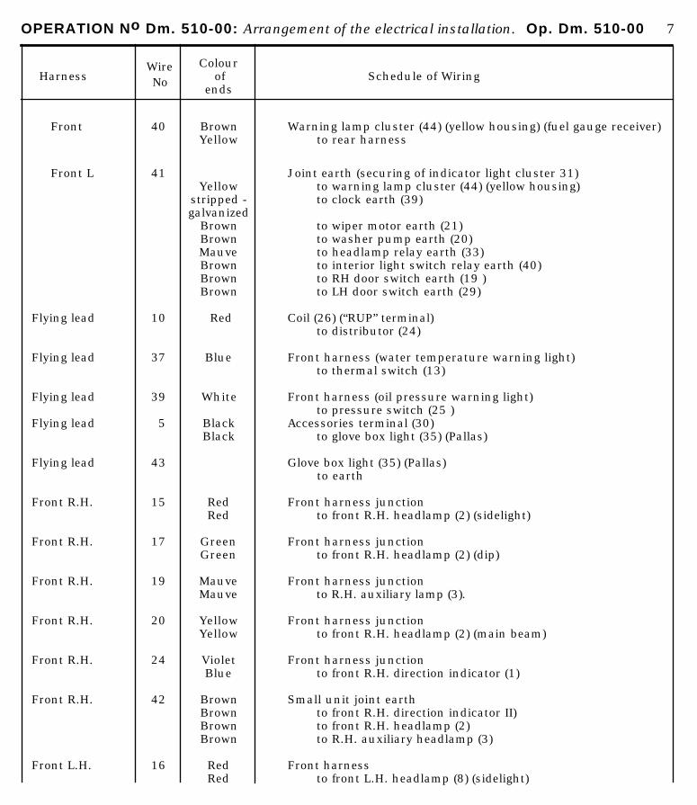
OPERATION No Dm. 510-00: Arrangement of the electrical installation. Op. Dm. 510-00 7
HarnessWire No
Colourof
ends Schedule of Wiring
Front 40 Brown Warning lamp cluster (44) (yellow housing) (fuel gauge receiver)Yellow to rear harness
Front L 41 Joint earth (securing of indicator light cluster 31)Yellow to warning lamp cluster (44) (yellow housing)
stripped - to clock earth (39)galvanized
Brown to wiper motor earth (21)Brown to washer pump earth (20)Mauve to headlamp relay earth (33)Brown to interior light switch relay earth (40)Brown to RH door switch earth (19 )Brown to LH door switch earth (29)
Flying lead 10 Red Coil (26) (“RUP” terminal) to distributor (24)
Flying lead 37 Blue Front harness (water temperature warning light) to thermal switch (13)
Flying lead 39 White Front harness (oil pressure warning light) to pressure switch (25 )
Flying lead 5 Black Accessories terminal (30)Black to glove box light (35) (Pallas)
Flying lead 43 Glove box light (35) (Pallas) to earth
Front R.H. 15 Red Front harness junctionRed to front R.H. headlamp (2) (sidelight)
Front R.H. 17 Green Front harness junctionGreen to front R.H. headlamp (2) (dip)
Front R.H. 19 Mauve Front harness junctionMauve to R.H. auxiliary lamp (3).
Front R.H. 20 Yellow Front harness junctionYellow to front R.H. headlamp (2) (main beam)
Front R.H. 24 Violet Front harness junctionBlue to front R.H. direction indicator (1)
Front R.H. 42 Brown Small unit joint earthBrown to front R.H. direction indicator II)Brown to front R.H. headlamp (2)Brown to R.H. auxiliary headlamp (3)
Front L.H. 16 Red Front harnessRed to front L.H. headlamp (8) (sidelight)

8 OPERATION No Dm 510-00: Arrangement of the electrical installation.
HarnessWire No
Colourof
ends Schedule of Wiring
Front L.H. 17 Green Front harnessGreen to front L.H. headlamp (8) (dip)
Front L.H. 19 Mauve Front harnessMauve to auxiliary L.H. headlamp (7)
Front L.H. 20 Yellow Front harnessYellow to front L.H. headlamp (8) (main beam)
Front L.H. 22 White Front harnessWhite to left horn (5)White to right horn (4) (DJ)
Front L.H. 23 Blue Front harnessBlue to first horn (6)
Front L.H. 25 Violet Front harnessBlue to front L.H. direction indicator (9)
Front L.H. 38 Grey Front harnessGrey to flying lead for brake pads (DJ)
Flying lead 38 Grey Front L.H. harnessGrey to brake pads (10) and (14) (DJ)
Front L.H. 42 Brown Small unit joint earthBrown to L.H. auxiliary headlamp (7)Brown to front L.H. headlamp (8)Brown to front L.H. direction indicator (9)
Rear 4 Black Front harness junction.Black to interior lamps (48). (51), (53) and (54) (DJ except PA)
Rear 14 Mauve Front harness junctionto boot lamp (52)
Mauve to rear R.H. number plate lamp (56)Mauve to rear L.H. number plate lamp (57)
Rear 15 Red Front harness junctionGreen to rear R.H. sidelight (56)
Rear 16 Green Front harness junctionGreen to rear L.H. sidelight (57)
Rear 24 Blue Front harness junctionBlue to rear R.H. direction indicator (55)
Rear 25 White Front harness junctionBlue to rear L.H. direction indicator (58)
Rear 32 Grey Front harness junctionto heated rear window (50) (optional)
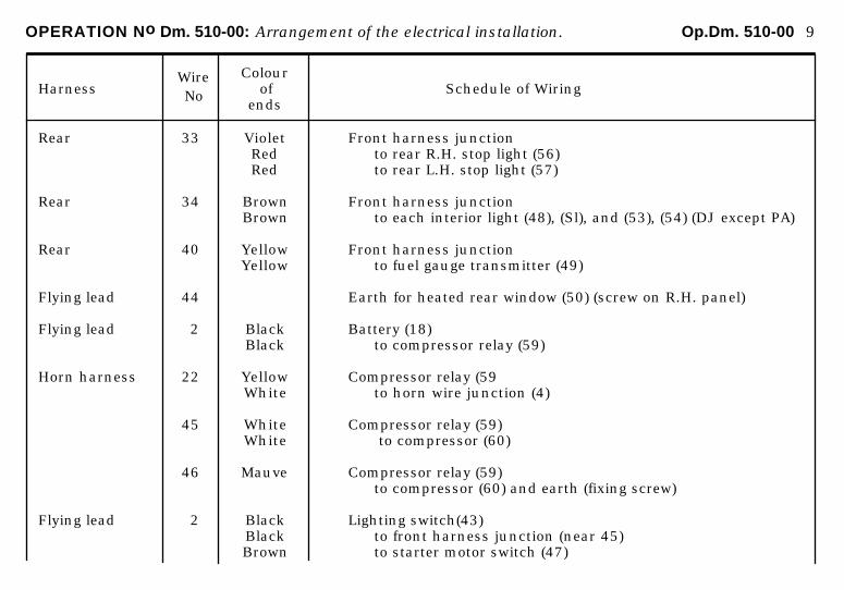
OPERATION No Dm. 510-00: Arrangement of the electrical installation. Op.Dm. 510-00 9
HarnessWire No
Colourof
ends Schedule of Wiring
Rear 33 Violet Front harness junctionRed to rear R.H. stop light (56)Red to rear L.H. stop light (57)
Rear 34 Brown Front harness junctionBrown to each interior light (48), (Sl), and (53), (54) (DJ except PA)
Rear 40 Yellow Front harness junctionYellow to fuel gauge transmitter (49)
Flying lead 44 Earth for heated rear window (50) (screw on R.H. panel)
Flying lead 2 Black Battery (18)Black to compressor relay (59)
Horn harness 22 Yellow Compressor relay (59White to horn wire junction (4)
45 White Compressor relay (59)White to compressor (60)
46 Mauve Compressor relay (59)to compressor (60) and earth (fixing screw)
Flying lead 2 Black Lighting switch(43)Black to front harness junction (near 45)Brown to starter motor switch (47)

OPERATION No. Dm 510-00 a : irrcurg:rn,c~n/ o/ thts elcc~trir~cd ins tdlrltirm Op. Dw 510-00 a
FlTTlNG THE ELE Cf RICAL INSTALLATION
New presentation of the “fitting the electrical instollotion” Operations :
Henceforth these operations will consist of two parts : -0 basic diogrom ond list of ports replocing the list of wires used
beforehand. . on installation diagram identical to the previous wiring diagram.
.Jdvantages of the basic diagram :
- It clearly indicates the circuits constituting the different functions of the installation.
- It facilitates the location of faults.

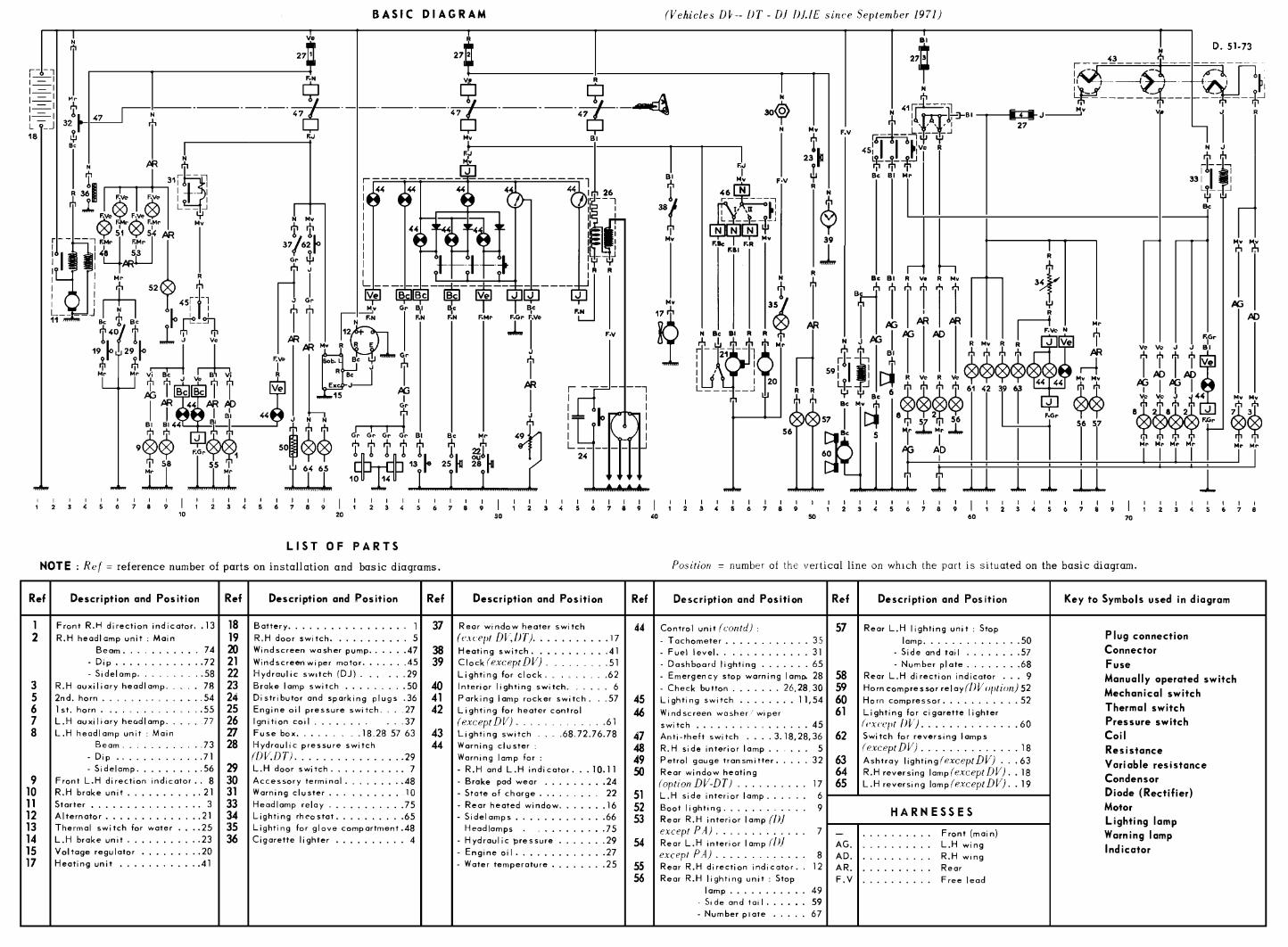
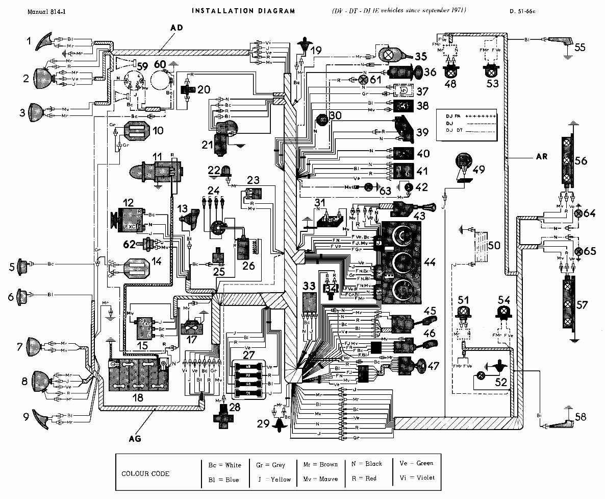
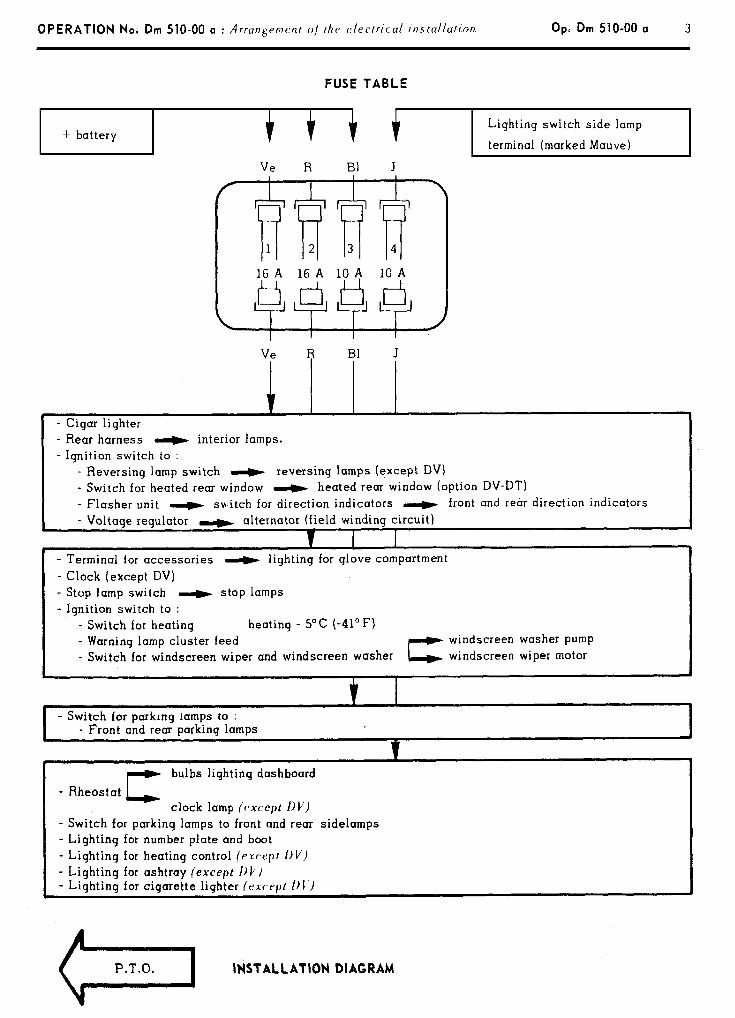
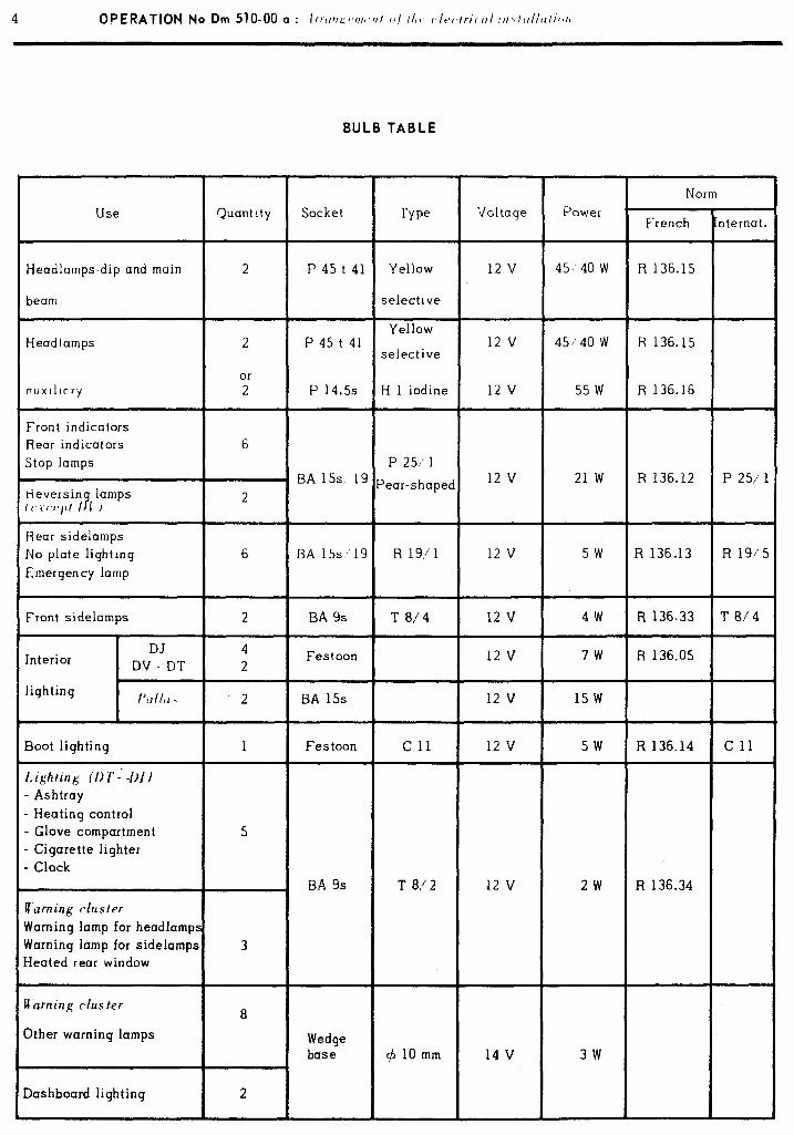
SULB TABLE
Use C&ant ity Socket Type Voltaqe Power Norm
French Internat.
Headlamps-dip and main
beam
Headlamps
cwxlllc~ry
Front indicators Rear indicators Stop lamps
Reversin lamps
fl~\w/Jt I 3 1 I
2
2
Or
2
6
2
P 45 t 41 Yellow 12 V 45 4ow R 136.15
selective
Yellow P 45 t 41 12 v 45)‘40 w R 136.15
selective
P 14.5s H 1 iodine 12 v 55 w R 136.16
P 251 I BA 15s 19 12 v 21 w R 136.12 P 25/ 1 Pear-shaped
Rear sidelamps No plate lighting
Emergency lamp
6 BA 15s,‘19 R 19/ 1 12 v 5w R 136.13 R 19/‘:
Front sidelamps 2 BA 9s T 8/4 12 v 4w R 136.33 T 8/4
DJ 4 Interior Festoon 12 v 7w
DV - DT R 136.05
2
lighting I’,IllU \ 2 BA 15s 12 v 15 w
Boot lighting 1 Festoon c 11 12 v 5w R 136.14 c 11
I,ighting /Di”- -I)J)
- Ashtray
. Heating control
. Glove compartment 5
. Cigarette lighter
. Clock BA 9s T 8,‘2 12 v 2w R 136.34
J arning cluster
Naming lamp for headlamps Naming lamp for sidelamps 3 -leated rear window
J’arning c/us ter
Ither warning lamps
lashboard lighting
8
Wedge base (b 10 mm 14 v 3w
2
i
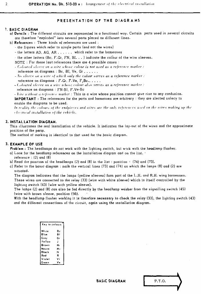
PRESENTATION OF THE DIAGRAMS
1. BASIC DIAGRAM a) Details : The different circuits are represented in a functional way. Certain parts used in several circuits
are therefore “explcded” into several parts placed on different lines.
b) References : Three kinds of references are used : - the figures which refer to single parts (and not the wires)
- the letters AD, AG, AR , . . . , , which refer to the harnesses
- the other letters (Bc, F.Gr, FN, BI. . . ) indicate the colbur of the wire sleeves. NOTE : For these last references there are 4 possible cases : - f.,J~,urt:d .\lt~t’~‘c on u wirr It.h~~~sc~ c.olour is not used as a rejerr~nc~t, mder :
reference on diagrams : Bc, BI, Ve, Gr . . . , . . - 40 slt:t*l,r WI u wirt* o/ Ichich only rhe colour serves as a reference morlier :
reference on diagrams : F.Gr, F.Ve, F.Bc.. . . , . - C.~,lourerl .slcr~cv on a wire whos(b ~01ou~ ul bo .serr’es as a relerenctz murkr,r
reference on diagrams : FN-91, F.Ve-Bc - II irra 14 irhotr/ tl rc~jvrc~nc~c, marker : This is a wire whose position cannot give rise to any confusion.
IMPORTANT : The references for the parts and harnesses are arbitrary : they are sleeted solecy to enable the diagrams to be used. III rt~ulil~ lhtp colour., o/ thv endpirc~r,s urrti wires are tht> ON/J rt,/(srt,n(.cP u.vctl (JII rhc wires muking II/) Iht,
~~lr~c~trcc.ul irr.slu/luriorr (I/ Ihe whir/r.
2. INSTALLATION DIAGRAM. This Illustrates the real installation of the vehicle. It indicates the lay-out of the wires and the approximate position of the parts. The method of marking is identical to that used for the basic diagram.
3. EXAMPLE OF USE Problem : The headlamps do not work with the lighting switch, but work with the headlamp flasher. a) Look for the headlamp references on the installation diagram and on the list. 1
reference : (2) and (8) b) Read the posltlon of the headlamps (2) and (8) in the list : position = (74) and (73). c) Refer to the basic diagram : maik the vertical lines (73) and (74) on which the lamps (8) and (2) are
situated. The diagram indicates that the lamps (yellow sleeves) form part of the L.H. and R.H. wing harnesses. These wires are connected to the relay (33) (wire with white sleeve) which is itself controlled by the lighting switch (43) ( wire with yellow sleeve). The larhps (2) and (8) can also be fed directly by the headlamp w&her from the signalling switch (45) (wire with brown sleeve, position (56). - With the headlamp flasher working it is therefore necessary to check,the relay (33), the lighting switch (43) and the different connections of the circuit, again using the installation diagram.
BASIC DIAGRAM
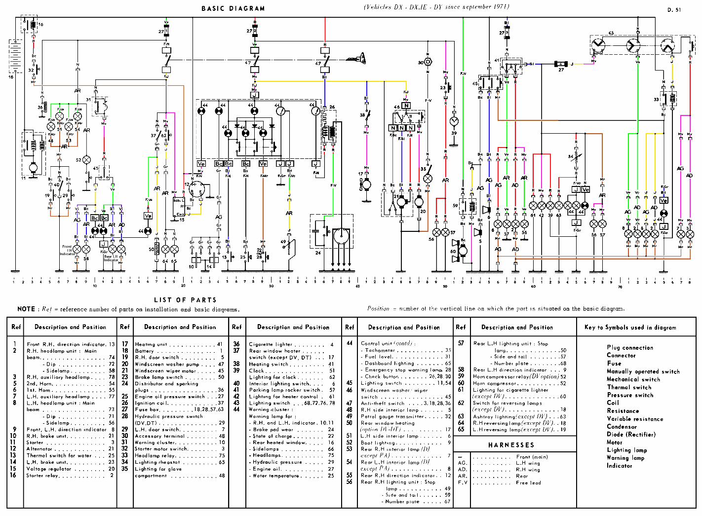
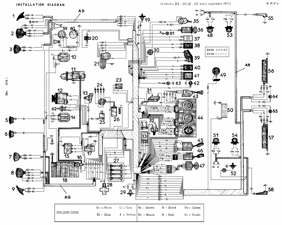
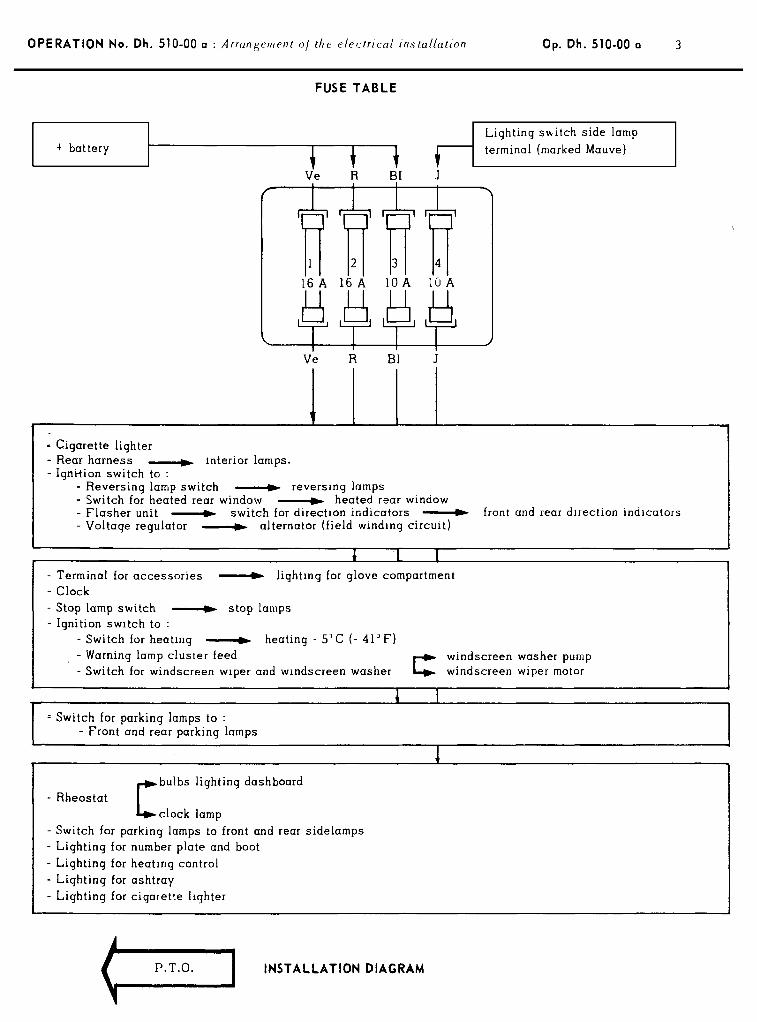
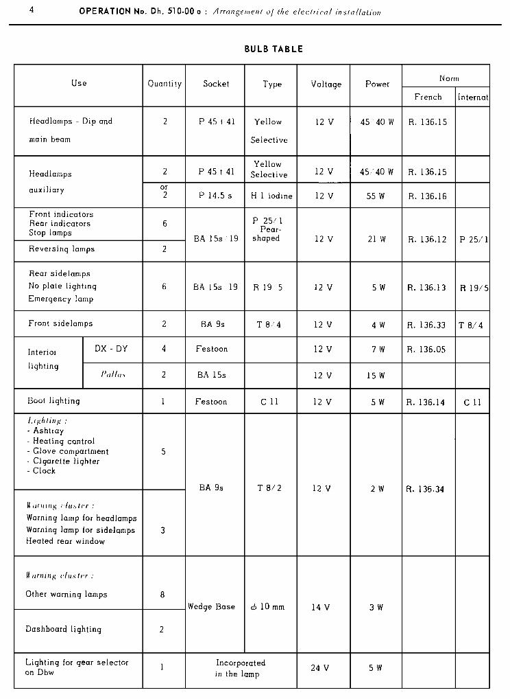
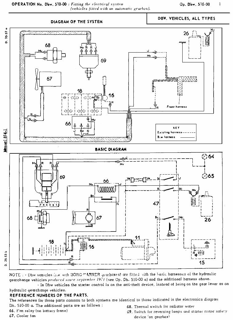
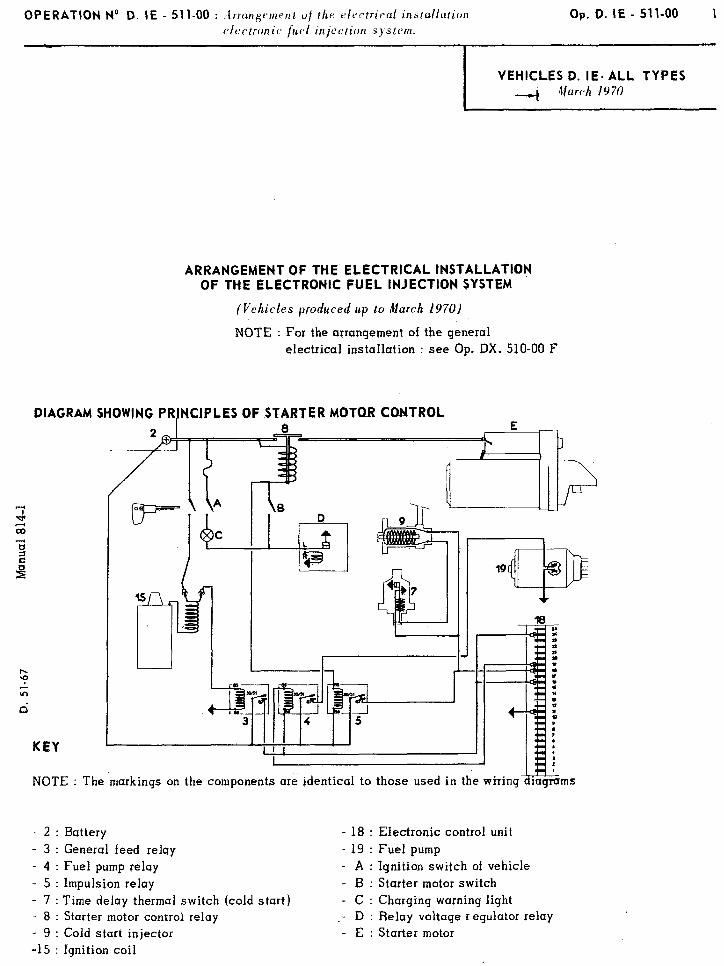
OPERATION No D. IE - 511-00 : frrnngcment of thr rirctricul installation electronic {uel injection .system.
Op. 0. IE - 511-00 1
VEHICLES D. IE- ALL TYPES 4 March 1970
KEY
ARRANGEMENT OF THE ELECTRICAL INSTALLATION OF THE ELECTRONIC FUEL INJECTION SYSTEM
(Vehicles produced up to March 1970)
NOTE : For the arrangement of the general electrical installation : see Op. DX. 510-00 F
- 2 Battery -3 General feed relay - 4 Fuel pump relay -5 Impulsion relay -7 Time delay thermal switch (cold start) -8 Starter motor control relay -9 Cold start injector -15 Ignition coil
NOTE : The markings on the components are identical to those used in the wiring
- 18 : Electronic control unit - 19 : Fuel pump - A : Ignition switch of vehicle - B : Starter motor switch - C : Charging warning light
_- D : Relay voltage r equlator relay - E : Starter motor
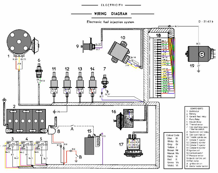
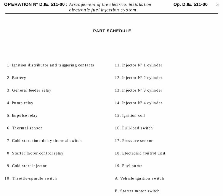
OPERATION Nº D.IE. 511-00 : Arrangement of the electrical installation Op. D.IE. 511-00 3electronic fuel injection system.
PART SCHEDULE
1. Ignition distributor and triggering contacts
2. Battery
3. General feeder relay
4. Pump relay
5. Impulse relay
6. Thermal sensor
7. Cold start time delay thermal switch
8. Starter motor control relay
9. Cold start injector
10. Throttle-spindle switch
11. Injector Nº 1 cylinder
12. Injector Nº 2 cylinder
13. Injector Nº 3 cylinder
14. Injector Nº 4 cylinder
15. Ignition coil
16. Full-load switch
17. Pressure sensor
18. Electronic control unit
19. Fuel pump
A. Vehicle ignition switch
B. Starter motor switch

OPERATION Nº D.IE. 511-00 : Arrangement of the electrical installation. Op. D.IE. 511-00 5electronic fuel injection system.
HarnessWireNº
Colourof
endsWiring schedule
Electroniccontrol unit
-do-
-do-
-do-
-do-
-do-
-do-
-do-
-do-
-do-
-do-
-do-
-do-
-do-
1
2
3
4
5
6
7
8
9
10
11
12
13
14
BlackBlackBlackBlackYellow
Yellow -brownBrownWhiteMauve
MauveViolet
YellowYellow
WhiteWhite
MauveRedRed
VioletWhiteVioletBlue
Green -greyGrey
Green-brownBrown
Yellow-violetViolet
Yellow-greenYellow
Red-blueBlue
Yellow-whiteYellow
BlueBlue
Starter motor control relay (8) (+ ve battery)to general feeder relay (3) (terminal 30/51)to pump relay (4) (terminal 30/51)to impulse relay (5) (terminal 30/51)to impulse relay (5) (terminal 85)
Electronic control unit (18) (terminal 16)Electronic control unit (18) (terminal 24)
to general feeder relay (3) (terminal 87)to pump relay (4) (terminal 86)
General feeder relay (3) (terminal 86)to ignition coil (15) (+ve terminal) (vehicle ignition switch A)
Pump relay (4) (terminal 85)to electronic control unit (18) (terminal 19)
Pump relay (4) (terminal 87)to fuel pump feed wire (19)
Impulse relay (5) (terminal 86)to starter motor control relay (8)to front cables of vehicle (starter motor switch B)
Electronic control unit (18) (terminal 18)to impulse relay (5) (terminal 87)to cold-start injector (9)to cold start time delay thermal switch (7)
Electronic control unit (18) (terminal 7)to pressure sensor (17) (terminal 7)
Electronic control unit (18) (terminal 8)to pressure sensor (17) (terminal 8)
Electronic control unit (18) (terminal 10)to pressure sensor (17) (terminal 10)
Electronic control unit (18) (terminal 15)to pressure sensor (17) (terminal 15)
Electronic control unit (18) (terminal 2)to full lead switch (16)
Electronic control unit (18) (terminal 9)to throttle spindle switch (10)
Electronic control unit (18) (terminal 20)to throttle spindle switch (10)
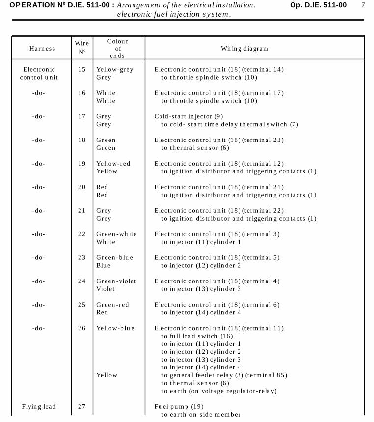
OPERATION Nº D.IE. 511-00 : Arrangement of the electrical installation. Op. D.IE. 511-00 7electronic fuel injection system.
HarnessWireNº
Colourof
endsWiring diagram
Electroniccontrol unit
-do-
-do-
-do-
-do-
-do-
-do-
-do-
-do-
-do-
-do-
-do-
Flying lead
15
16
17
18
19
20
21
22
23
24
25
26
27
Yellow-greyGrey
WhiteWhite
GreyGrey
GreenGreen
Yellow-redYellow
RedRed
GreyGrey
Green-whiteWhite
Green-blueBlue
Green-violetViolet
Green-redRed
Yellow-blue
Yellow
Electronic control unit (18) (terminal 14)to throttle spindle switch (10)
Electronic control unit (18) (terminal 17)to throttle spindle switch (10)
Cold-start injector (9)to cold- start time delay thermal switch (7)
Electronic control unit (18) (terminal 23)to thermal sensor (6)
Electronic control unit (18) (terminal 12)to ignition distributor and triggering contacts (1)
Electronic control unit (18) (terminal 21)to ignition distributor and triggering contacts (1)
Electronic control unit (18) (terminal 22)to ignition distributor and triggering contacts (1)
Electronic control unit (18) (terminal 3)to injector (11) cylinder 1
Electronic control unit (18) (terminal 5)to injector (12) cylinder 2
Electronic control unit (18) (terminal 4)to injector (13) cylinder 3
Electronic control unit (18) (terminal 6)to injector (14) cylinder 4
Electronic control unit (18) (terminal 11)to full load switch (16)to injector (11) cylinder 1to injector (12) cylinder 2to injector (13) cylinder 3to injector (14) cylinder 4to general feeder relay (3) (terminal 85)to thermal sensor (6)to earth (on voltage regulator-relay)
Fuel pump (19)to earth on side member
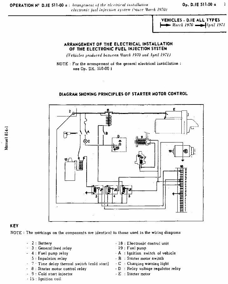
OPERATION No D.IE 511.00 Q : .lrrangement of the t:Icc&ricul insfaflution electronic fuel injection system firire tlarch 1970)
Op. D.IE 51 l-00 a 1
KEY
NOTE
I VEHiCLES - D.IE ALL TYPES
+ !vUarch 1970 4lpril 1971
ARRANGEMENT OF THE ELECTRICAL INSTALLATION OF THE ELECTRONIC FUEL INJECT!ON SYSTEM
(Vehicles produced between March 1970 and April 19711
: For the arrangement of the general electrical installation : see Op. DX. 510-00 f
DIAGRAM SHOWlNG PRINCIPLES OF STARTER MOTOR CONTROL
NOTE : The markings on the components are identicul to those used in the wiring diagrams
- 2 : Battery - 18 : Electronic control unit - 3 : General feed relay - 19 : Fuel pump - 4 : Fuel pump relay - A : Ignition switch of vehicle - 5 : Impulsion relay - B : Starter motor switch - 7 Time delay thermal switch (cold start) - C : Charging warning light - 8 : Starter motor control reiay - D : Relay voltage regulator relay - 9 : Cold start injector - E : Starter motor - 15 : Ignition coil
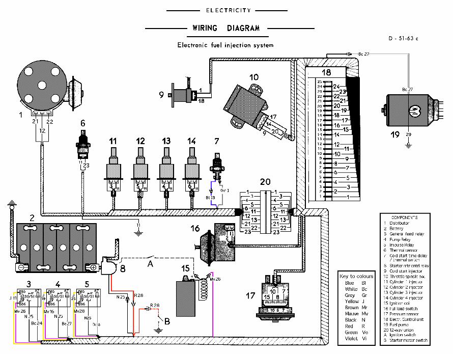
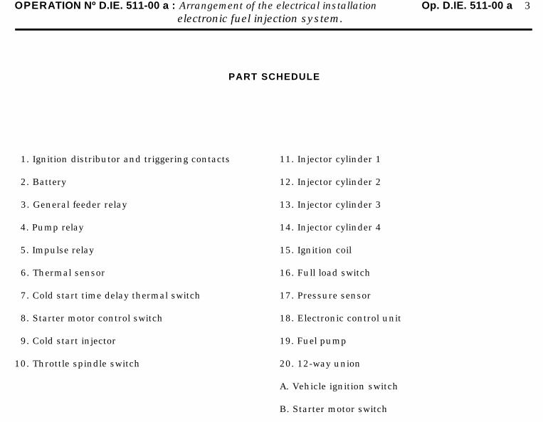
OPERATION Nº D.IE. 511-00 a : Arrangement of the electrical installation Op. D.IE. 511-00 a 3electronic fuel injection system.
PART SCHEDULE
1. Ignition distributor and triggering contacts
2. Battery
3. General feeder relay
4. Pump relay
5. Impulse relay
6. Thermal sensor
7. Cold start time delay thermal switch
8. Starter motor control switch
9. Cold start injector
10. Throttle spindle switch
11. Injector cylinder 1
12. Injector cylinder 2
13. Injector cylinder 3
14. Injector cylinder 4
15. Ignition coil
16. Full load switch
17. Pressure sensor
18. Electronic control unit
19. Fuel pump
20. 12-way union
A. Vehicle ignition switch
B. Starter motor switch
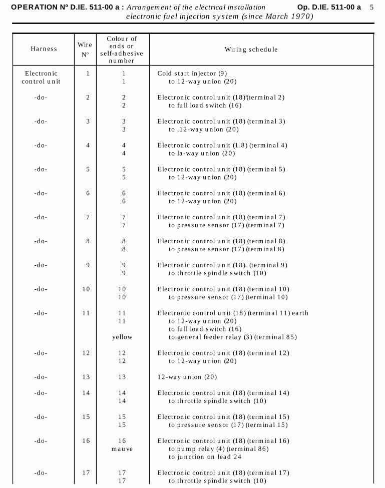
OPERATION Nº D.IE. 511-00 a : Arrangement of the electrical installation Op. D.IE. 511-00 a 5electronic fuel injection system (since March 1970)
HarnessWire
Nº
Colour ofends or
self-adhesivenumber
Wiring schedule
Electroniccontrol unit
-do-
-do-
-do-
-do-
-do-
-do-
-do-
-do-
-do-
-do-
-do-
-do-
-do-
-do-
-do-
-do-
1
2
3
4
5
6
7
8
9
10
11
12
13
14
15
16
17
11
22
33
44
55
66
77
88
99
1010
1111
yellow
1212
13
1414
1515
16mauve
1717
Cold start injector (9)to 12-way union (20)
Electronic control unit (18)‘(terminal 2)to full load switch (16)
Electronic control unit (18) (terminal 3)to ,12-way union (20)
Electronic control unit (1.8) (terminal 4)to la-way union (20)
Electronic control unit (18) (terminal 5)to 12-way union (20)
Electronic control unit (18) (terminal 6)to 12-way union (20)
Electronic control unit (18) (terminal 7)to pressure sensor (17) (terminal 7)
Electronic control unit (18) (terminal 8)to pressure sensor (17) (terminal 8)
Electronic control unit (18). (terminal 9)to throttle spindle switch (10)
Electronic control unit (18) (terminal 10)to pressure sensor (17) (terminal 10)
Electronic control unit (18) (terminal 11) earthto 12-way union (20)to full load switch (16)to general feeder relay (3) (terminal 85)
Electronic control unit (18) (terminal 12)to 12-way union (20)
12-way union (20)
Electronic control unit (18) (terminal 14)to throttle spindle switch (10)
Electronic control unit (18) (terminal 15)to pressure sensor (17) (terminal 15)
Electronic control unit (18) (terminal 16)to pump relay (4) (terminal 86)to junction on lead 24
Electronic control unit (18) (terminal 17)to throttle spindle switch (10)
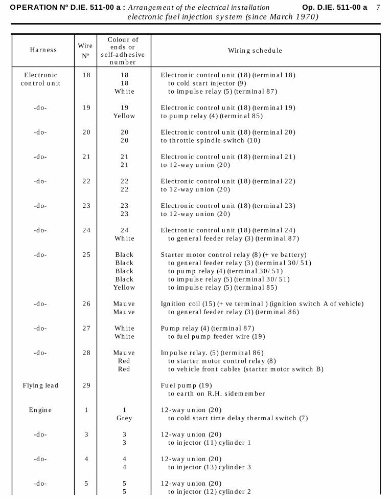
OPERATION Nº D.IE. 511-00 a : Arrangement of the electrical installation Op. D.IE. 511-00 a 7electronic fuel injection system (since March 1970)
HarnessWire
Nº
Colour ofends or
self-adhesivenumber
Wiring schedule
Electroniccontrol unit
-do-
-do-
-do-
-do-
-do-
-do-
-do-
-do-
-do-
-do-
Flying lead
Engine
-do-
-do-
-do-
18
19
20
21
22
23
24
25
26
27
28
29
1
3
4
5
1818
White
19Yellow
2020
2121
2222
2323
24White
BlackBlackBlackBlackYellow
MauveMauve
WhiteWhite
MauveRedRed
1Grey
33
44
55
Electronic control unit (18) (terminal 18)to cold start injector (9)to impulse relay (5) (terminal 87)
Electronic control unit (18) (terminal 19)to pump relay (4) (terminal 85)
Electronic control unit (18) (terminal 20)to throttle spindle switch (10)
Electronic control unit (18) (terminal 21)to 12-way union (20)
Electronic control unit (18) (terminal 22)to 12-way union (20)
Electronic control unit (18) (terminal 23)to 12-way union (20)
Electronic control unit (18) (terminal 24)to general feeder relay (3) (terminal 87)
Starter motor control relay (8) (+ ve battery)to general feeder relay (3) (terminal 30/51)to pump relay (4) (terminal 30/51)to impulse relay (5) (terminal 30/51)to impulse relay (5) (terminal 85)
Ignition coil (15) (+ ve terminal ) (ignition switch A of vehicle)to general feeder relay (3) (terminal 86)
Pump relay (4) (terminal 87)to fuel pump feeder wire (19)
Impulse relay. (5) (terminal 86)to starter motor control relay (8)to vehicle front cables (starter motor switch B)
Fuel pump (19)to earth on R.H. sidemember
12-way union (20)to cold start time delay thermal switch (7)
12-way union (20)to injector (11) cylinder 1
12-way union (20)to injector (13) cylinder 3
12-way union (20)to injector (12) cylinder 2
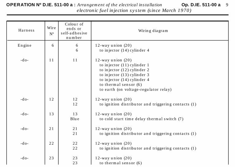
OPERATION Nº D.IE. 511-00 a : Arrangement of the electrical installation Op. D.IE. 511-00 a 9electronic fuel injection system (since March 1970)
HarnessWire
Nº
Colour ofends or
self-adhesivenumber
Wiring diagram
Engine
-do-
-do-
-do-
-do-
-do-
-do-
6
11
12
13
21
22
23
6 6
11
1212
13Blue
2121
2222
2323
12-way union (20)to injector (14) cylinder 4
12-way union (20)to injector (11) cylinder 1to injector (12) cylinder 2to injector (13) cylinder 3to injector (14) cylinder 4to thermal sensor (6)to earth (on voltage-regulator relay)
12-way union (20)to ignition distributor and triggering contacts (1)
12-way union (20)to cold start time delay thermal switch (7)
12-way union (20)to ignition distributor and triggering contacts (1)
12-way union (20)to ignition distributor and triggering contacts (1)
12-way union (20)to thermal sensor (6)
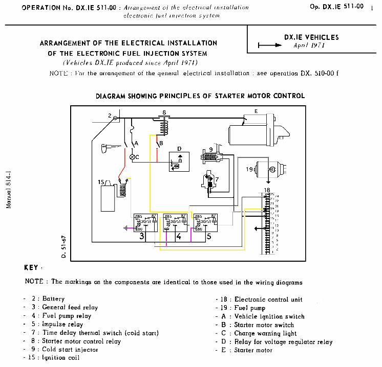
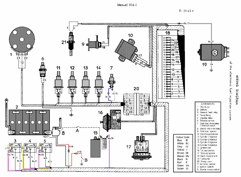
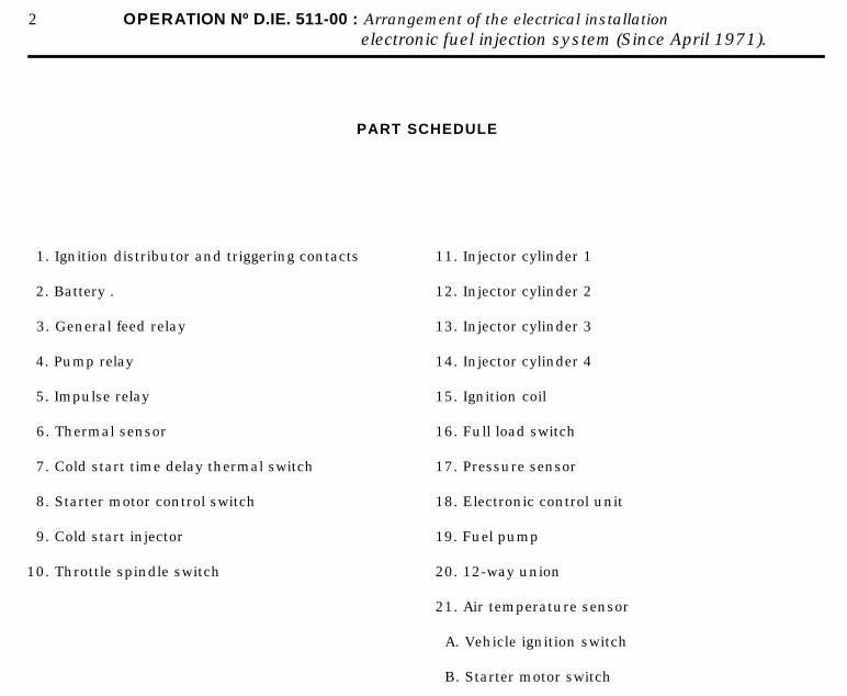
2 OPERATION Nº D.IE. 511-00 : Arrangement of the electrical installationelectronic fuel injection system (Since April 1971).
PART SCHEDULE
1. Ignition distributor and triggering contacts
2. Battery .
3. General feed relay
4. Pump relay
5. Impulse relay
6. Thermal sensor
7. Cold start time delay thermal switch
8. Starter motor control switch
9. Cold start injector
10. Throttle spindle switch
11. Injector cylinder 1
12. Injector cylinder 2
13. Injector cylinder 3
14. Injector cylinder 4
15. Ignition coil
16. Full load switch
17. Pressure sensor
18. Electronic control unit
19. Fuel pump
20. 12-way union
21. Air temperature sensor
A. Vehicle ignition switch
B. Starter motor switch
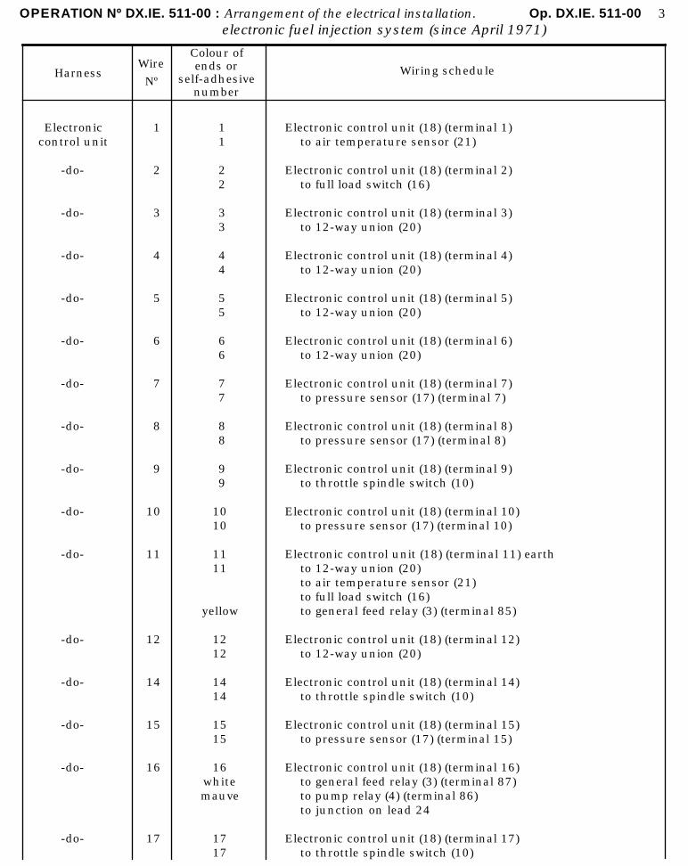
OPERATION Nº DX.IE. 511-00 : Arrangement of the electrical installation. Op. DX.IE. 511-00 3electronic fuel injection system (since April 1971)
HarnessWire
Nº
Colour ofends or
self-adhesivenumber
Wiring schedule
Electroniccontrol unit
-do-
-do-
-do-
-do-
-do-
-do-
-do-
-do-
-do-
-do-
-do-
-do-
-do-
-do-
-do-
1
2
3
4
5
6
7
8
9
10
11
12
14
15
16
17
11
22
33
44
55
66
77
88
99
1010
1111
yellow
1212
1414
1515
16whitemauve
1717
Electronic control unit (18) (terminal 1)to air temperature sensor (21)
Electronic control unit (18) (terminal 2)to full load switch (16)
Electronic control unit (18) (terminal 3)to 12-way union (20)
Electronic control unit (18) (terminal 4)to 12-way union (20)
Electronic control unit (18) (terminal 5)to 12-way union (20)
Electronic control unit (18) (terminal 6)to 12-way union (20)
Electronic control unit (18) (terminal 7)to pressure sensor (17) (terminal 7)
Electronic control unit (18) (terminal 8)to pressure sensor (17) (terminal 8)
Electronic control unit (18) (terminal 9)to throttle spindle switch (10)
Electronic control unit (18) (terminal 10)to pressure sensor (17) (terminal 10)
Electronic control unit (18) (terminal 11) earthto 12-way union (20)to air temperature sensor (21)to full load switch (16)to general feed relay (3) (terminal 85)
Electronic control unit (18) (terminal 12)to 12-way union (20)
Electronic control unit (18) (terminal 14)to throttle spindle switch (10)
Electronic control unit (18) (terminal 15)to pressure sensor (17) (terminal 15)
Electronic control unit (18) (terminal 16)to general feed relay (3) (terminal 87)to pump relay (4) (terminal 86)to junction on lead 24
Electronic control unit (18) (terminal 17)to throttle spindle switch (10)
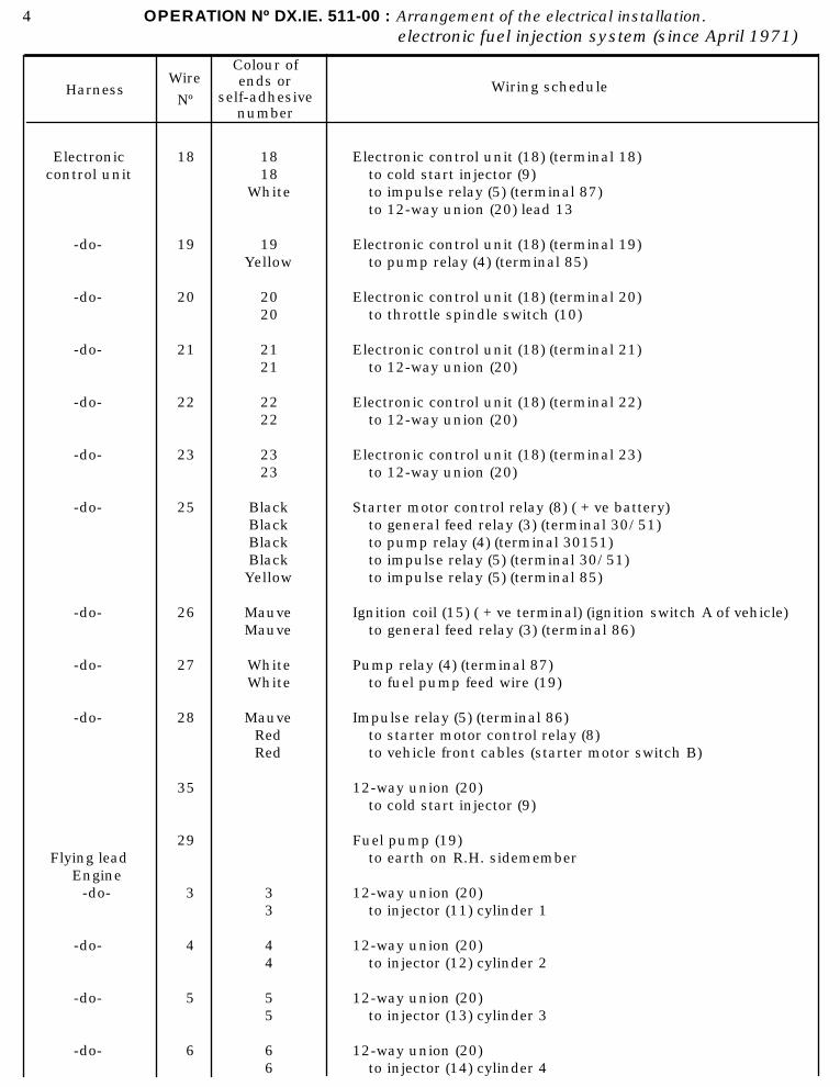
4 OPERATION Nº DX.IE. 511-00 : Arrangement of the electrical installation.electronic fuel injection system (since April 1971)
HarnessWire
Nº
Colour ofends or
self-adhesivenumber
Wiring schedule
Electroniccontrol unit
-do-
-do-
-do-
-do-
-do-
-do-
-do-
-do-
-do-
Flying leadEngine
-do-
-do-
-do-
-do-
18
19
20
21
22
23
25
26
27
28
35
29
3
4
5
6
1818
White
19Yellow
2020
2121
2222
2323
BlackBlackBlackBlack Yellow
MauveMauve
WhiteWhite
MauveRedRed
33
44
55
66
Electronic control unit (18) (terminal 18)to cold start injector (9)to impulse relay (5) (terminal 87)to 12-way union (20) lead 13
Electronic control unit (18) (terminal 19)to pump relay (4) (terminal 85)
Electronic control unit (18) (terminal 20)to throttle spindle switch (10)
Electronic control unit (18) (terminal 21)to 12-way union (20)
Electronic control unit (18) (terminal 22)to 12-way union (20)
Electronic control unit (18) (terminal 23)to 12-way union (20)
Starter motor control relay (8) ( + ve battery)to general feed relay (3) (terminal 30/51)to pump relay (4) (terminal 30151)to impulse relay (5) (terminal 30/51)to impulse relay (5) (terminal 85)
Ignition coil (15) ( + ve terminal) (ignition switch A of vehicle)to general feed relay (3) (terminal 86)
Pump relay (4) (terminal 87)to fuel pump feed wire (19)
Impulse relay (5) (terminal 86)to starter motor control relay (8)to vehicle front cables (starter motor switch B)
12-way union (20)to cold start injector (9)
Fuel pump (19)to earth on R.H. sidemember
12-way union (20)to injector (11) cylinder 1
12-way union (20)to injector (12) cylinder 2
12-way union (20)to injector (13) cylinder 3
12-way union (20)to injector (14) cylinder 4
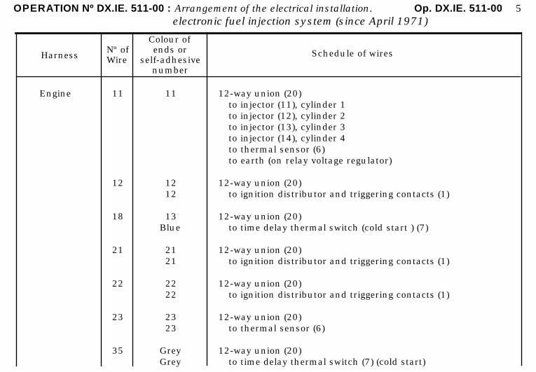
OPERATION Nº DX.IE. 511-00 : Arrangement of the electrical installation. Op. DX.IE. 511-00 5electronic fuel injection system (since April 1971)
HarnessNº ofWire
Colour ofends or
self-adhesivenumber
Schedule of wires
Engine 11
12
18
21
22
23
35
11
1212
13Blue
2121
2222
2323
GreyGrey
12-way union (20)to injector (11), cylinder 1to injector (12), cylinder 2to injector (13), cylinder 3to injector (14), cylinder 4to thermal sensor (6)to earth (on relay voltage regulator)
12-way union (20)to ignition distributor and triggering contacts (1)
12-way union (20)to time delay thermal switch (cold start ) (7)
12-way union (20)to ignition distributor and triggering contacts (1)
12-way union (20)to ignition distributor and triggering contacts (1)
12-way union (20)to thermal sensor (6)
12-way union (20)to time delay thermal switch (7) (cold start)
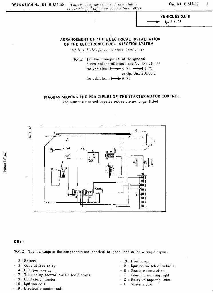
KEY :
ARRANGEMENT OF THE E;LECTRlCAL INSTALLATION OF THE ELECTRONIC FUEL INJECTION SYSTEM
~ill.ll: I tt/rt, II*, ,,rtl*/uc t,d ,,IL~ f’ Il,fi/ IYYI I
NGTE : For the arrangement of the general electrical installation : see 3p grn 510-00
for vehicles : M 4 71 _)( 9.‘71
or Op. Dm. 510.00 a
for vehicles : -9,‘71
DIAGRAM SHOWING THE PRINCIPLES OF THE STARTER MOTOR CONTROL The starter motor and impulse relays are no longer fitted
NGTE : The markings of the components are identical to those used in the wiring diagram.
- 2 : Battery - 3 : General feed relay - 4 : Fuel pump relay - 7 : Time delay thermal switch (cold start) - 9 : Cold start injector - 15 : Ignition coil - 18 : Electronic control unit
- 19 : Fuel pump - A : Ignition switch of vehicle - B : Starter motor switch - C : Charging warning light - D : Relay voltage regulator - E : Starter motor
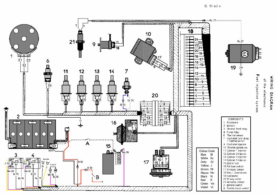
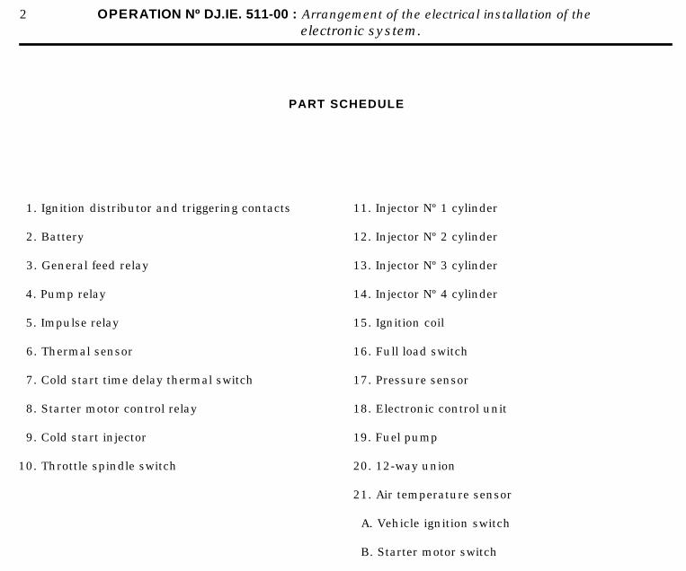
2 OPERATION Nº DJ.IE. 511-00 : Arrangement of the electrical installation of theelectronic system.
PART SCHEDULE
1. Ignition distributor and triggering contacts
2. Battery
3. General feed relay
4. Pump relay
5. Impulse relay
6. Thermal sensor
7. Cold start time delay thermal switch
8. Starter motor control relay
9. Cold start injector
10. Throttle spindle switch
11. Injector Nº 1 cylinder
12. Injector Nº 2 cylinder
13. Injector Nº 3 cylinder
14. Injector Nº 4 cylinder
15. Ignition coil
16. Full load switch
17. Pressure sensor
18. Electronic control unit
19. Fuel pump
20. 12-way union
21. Air temperature sensor
A. Vehicle ignition switch
B. Starter motor switch
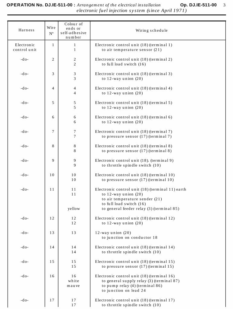
OPERATION No. DJ.IE-511-00 : Arrangement of the electrical installation Op. DJ.IE-511-00 3electronic fuel injection system (since April 1971)
HarnessWire
Nº
Colour ofends or
self-adhesivenumber
Wiring schedule
Electroniccontrol unit
-do-
-do-
-do-
-do-
-do-
-do-
-do-
-do-
-do-
-do-
-do-
-do-
-do-
-do-
-do-
-do-
1
2
3
4
5
6
7
8
9
10
11
12
13
14
15
16
17
11
22
33
44
55
66
77
88
99
1010
1111
yellow
1212
13
1414
1515
16whitemauve
1717
Electronic control unit (18) (terminal 1)to air temperature sensor (21)
Electronic control unit (18) (terminal 2)to full load switch (16)
Electronic control unit (18) (terminal 3)to 12-way union (20)
Electronic control unit (18) (terminal 4)to 12-way union (20)
Electronic control unit (18) (terminal 5)to 12-way union (20)
Electronic control unit (18) (terminal 6)to 12-way union (20)
Electronic control unit (18) (terminal 7)to pressure sensor (17) (terminal 7)
Electronic control unit (18) (terminal 8)to pressure sensor (17) (terminal 8)
Electronic control unit (18). (terminal 9)to throttle spindle switch (10)
Electronic control unit (18) (terminal 10)to pressure sensor (17) (terminal 10)
Electronic control unit (18) (terminal 11) earthto 12-way union (20)to air temperature sender (21)to full load switch (16)to general feeder relay (3) (terminal 85)
Electronic control unit (18) (terminal 12)to 12-way union (20)
12-way union (20)to junction on conductor 18
Electronic control unit (18) (terminal 14)to throttle spindle switch (10)
Electronic control unit (18) (terminal 15)to pressure sensor (17) (terminal 15)
Electronic control unit (18) (terminal 16)to general supply relay (3) (terminal 87)to pump relay (4) (terminal 86)to junction on lead 24
Electronic control unit (18) (terminal 17)to throttle spindle switch (10)
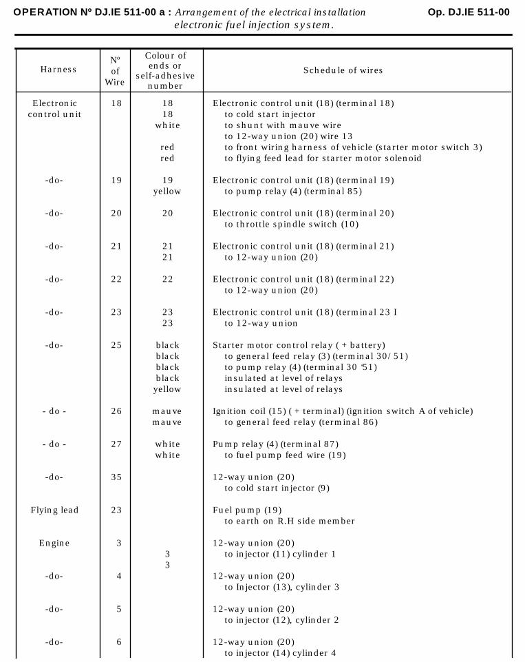
OPERATION Nº DJ.IE 511-00 a : Arrangement of the electrical installation Op. DJ.IE 511-00 electronic fuel injection system.
HarnessNºof
Wire
Colour ofends or
self-adhesivenumber
Schedule of wires
Electroniccontrol unit
-do-
-do-
-do-
-do-
-do-
-do-
- do -
- do -
-do-
Flying lead
Engine
-do-
-do-
-do-
18
19
20
21
22
23
25
26
27
35
23
3
4
5
6
1818
white
redred
19yellow
20
2121
22
2323
blackblackblackblackyellow
mauvemauve
whitewhite
33
Electronic control unit (18) (terminal 18)to cold start injectorto shunt with mauve wireto 12-way union (20) wire 13to front wiring harness of vehicle (starter motor switch 3)to flying feed lead for starter motor solenoid
Electronic control unit (18) (terminal 19)to pump relay (4) (terminal 85)
Electronic control unit (18) (terminal 20)to throttle spindle switch (10)
Electronic control unit (18) (terminal 21)to 12-way union (20)
Electronic control unit (18) (terminal 22)to 12-way union (20)
Electronic control unit (18) (terminal 23 Ito 12-way union
Starter motor control relay ( + battery)to general feed relay (3) (terminal 30/51)to pump relay (4) (terminal 30 ‘51)insulated at level of relaysinsulated at level of relays
Ignition coil (15) ( + terminal) (ignition switch A of vehicle)to general feed relay (terminal 86)
Pump relay (4) (terminal 87)to fuel pump feed wire (19)
12-way union (20)to cold start injector (9)
Fuel pump (19)to earth on R.H side member
12-way union (20)to injector (11) cylinder 1
12-way union (20)to Injector (13), cylinder 3
12-way union (20)to injector (12), cylinder 2
12-way union (20)to injector (14) cylinder 4

OPERATION Nº DJ.IE-511-00 a : Arrangement of the electrical installation Op. DJ.IE-511-00 5electronic fuel injection system (since April 1971)
Harness Nº ofWire
Colour ofends or
self-adhesivenumber
Schedule of wires
Engine
-do-
-do-
-do-
-do-
-do-
-do-
-do-
6
11
12
13
21
22
23
35
66
11
1212
13Blue
2121
2222
2323
Grey
12-way union (20)to injector (14) cylinder 4
12-way union (20)to injector (11) cylinder 1to injector (12) cylinder 2to injector (13) cylinder 3to injector (14) cylinder 4to thermal sensor (6)to earth (on relay voltnge regulator)
12-way union (20)to ignition distributor and triggering contacts (1)
12-way union (20)to time delay thermal switch (cold start) (7)
12-way union (20)to ignition distributor and triggering contacts (1)
12-way union (20)to ignition distributor and triggering contacts (1)
12-way union (20)to thermal sensor (6)
12-way union (20)to time delay thermal switch (7) (cold start)
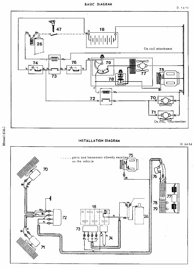
BASIC DIAGRAM D. ha-53
-J 1 -I
bv 76
* --!
L
INSTALLATION DIAGRAM D. 64-54
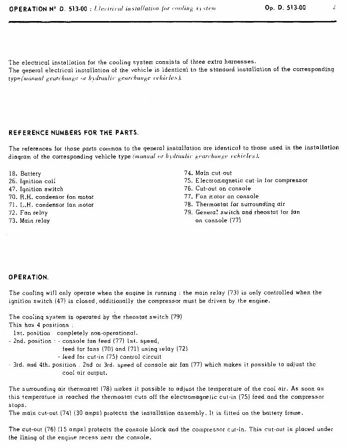
Op. D. 513-00 2
The electrical installation for the cooling system consists of three extra harnesses. The general electrical installation of the vehicle is identical to the standard installation of the corresponding type (I~~w~u~~I ~curc./~uugc f,r If \ tlrctrrlic~ ~f:ctrc~hcrrc~e cx,hic~la.s 1.
REFERENCE NUMBERS FOR THE PARTS.
The references for those parts common to the general installation are identical to those used in the installation diagram of the corresponding vehicle type (r~~w~ud or Ir?-tlruulic gvtrrc,/lclugc rxhic,ks ).
18. Battery 26. Ignition coil 47. Ignition switch 70. R.H. condenser fan motor 71. L.H. condenser fan motor 72. Fan relay 73. Main relay
74. Main cut-out 75. Electromagnetic cut,-in for compressor 76. Cut-out on console 77. Fan motor on console 78. Thermostat for surrounding air 79. General switch and rheostat for fan
on console (77)
OPERATION.
The cooling will only operate when the engine is running : the main relay (73) is only controlled when the ignition switch (47) is closed, additionally the compressor must be driven by the engine.
The cooling system is operated by the rheostat switch (79) This has 4 positions :
1st. position : completely non-operational. 2nd. position : - console fan feed (77) 1st. speed,
feed for fans (70) and (71) usinq relay (72) - feed for cut-in (75) control circuit
- 3rd. and 4th. position : 2nd or 3rd. speed of console air fan (77) which makes it possible to adjust the cool air output.
The surroundinq air thermostat (78) makes it possible to adjust the temperature of the cool air. As soon as this temperature is reached the thermostat cuts off the electromagnetic cut-in (75) feed and the compressor stops. The main cut-out (74) (30 amps) protects the installation assembly. It is fitted on the battery frame.
The cut-out (76) (15 amps) protects the console block and the compressor cut-in. This cut-out is placed under the lining of the engine recess near the console.


2 OPERATION No D. 530-O : Ch aracterislics und chechs on electrical units
- Vehicles all t)pt,.s (1. vcept DX-DJ-DXF-DI F)
Period of use
Brand name of starter motor
Type of starter motor
---d9/ 1968 +99/ 68 49/ 69 +- 9/1969
DUCELLIER PARIS-RHONE PARIS-RHONE DUCELLIER
6201 A (l)r) 6166 A DlOB45 D 10E 49
6215 A (DV, DT)
II - RE-SKIMMING 1 - Dynamos :
Brand name of dynamo DUCELLIER PARIS-RHONE
Type of dynamo 7327 A 7336 A G 1OC 39 G lOC44
orG lOC48
Minimum diameter after skimming of commutator
35 mm 36 mm 34,s mm 34,5 mm
2 - Starter motors :
Brand name of starter motor
Type of starter motor
Minimum diameter after skimming of commutator
DUCELLIER PARIS-RHONE
6164 A - 6166 A 6201 A D 10 B 45 D 10 E 52 6182 A - 6200 A 6215 A D 11 B 116 D 10E 49 D 10 E 55
6225 A D 11 E 123
395 mm 31 mm 43 mm 39 5 mm 40 mm
Ill - TESTS ON A TEST BENCH OR ON THE VEHICLE 1. Dynamos
Dynamo without regulator : yellow wire ((EXC,, joined to red wire ((DYN,) and black wire to earth.
DUCELLIER 7327 A or DUCELLIER PARIS-RHONE Brand name and type of dynamo
PARIS-RHONE G 10 C 39 7336 A GGl C1]oCc4i80r
Cold starting speed at 13 V 1200 rpm 1950 rpm 1700 rpm
Output when cold at 13 V 3,,S A to 1500 rpm 11 A to 2200 rpm 19.5 A to 2200 rpm
22 A to 2500 rpm 29 A to 3000 rpm 33 A to 3000 rpm
2. Alternators : a) First case :
- I I,/~i,./rs 4.T. 4 3/ 1971 : PARIS-RHONE A 13 R 52, or DUCELLIER 7530 A and 7530 B - Vehicles A.T. + 3/197J : PARIS-RHONE A 13 R 109 and A 13 R 110, or DUCELLIER 7551 A and 7551 -
- Ratio of alternator/engine rotation speed : 4311971 = 1:.53/l t--3,’ 1971 = 1:.75/ 1
- Trials on test-bench without regulator : join terminal ((EXC)) to ((+ 1) termina1. - Output when cold at 14 V : 16 A 1650 r.p.m. and 35 A at 3600 r.p.m. alternator.
b) Second case :
- I’ehicles all types (except DV) with air conditioner and vehicles all types +- 5/1972
- PARIS-RHONE A 13 R 119 or DUCELLIER 7558 A - Ratio of alternator/ engine rotation speed = l.75/ 1 - Trials on test bench without regulator-join terminal (( EXC )) to (( + )) terminal
- Output when cold at 14 V : 17.5 A at 1750 r.p.m. and 43 A at 3900 r.p.m. alternator.
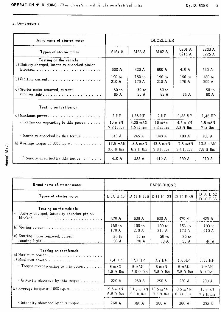
OPERATION No D. 530-O : Ch aracteristics and checks on electrical units. Op. D. 530-O 3
3. Dimarreurs :
Brand name of starter motor DUCELLIER
Types of starter motor
Testing on the vehicle
a) Battery charged, intensity absorbed pinion blocked. ........................
b) Starting current. ...................
c) Starter motor removed, current running light. .....................
6164 A I
6166 A 6182 A 6201 A 6200 A 6215 A 6225 A
600 A 420 A 600 A 410 A 520 A
190 to 150 to 190 to 150 to 180 to 210 A 170 A 210 A 170 A 200 A
50 to 30 to 50 to 50 to 85 A 50 A 85 A 35 A 60 A
Testing on test bench
a) Maximum power. ...................
- Torque corresponding to this power. .....
2 HP 1,35 HP 2 HP 1,25 HP 1,48 HP
- Intensity absorbed by this torque .......
b) Average torque at 1000 r.p.m. ..........
- Intensity absorbed by this torque .......
Brand nome of starter motor FARIS-RHONE
Types of starter motor
Testing on the vehicle
a) Battery charged, intensity absorber pinion blocked. .........................
b) Stating current ......................
c) Starting motor removed, current running light ......................
Testing on test bench
a) Maximum power. .................... I) Maximum power. ....................
- Torque corresponding to this power. ......
470 A 630 A 630 A 470 A 425 A ,-_.
150 to 190 to 190 to 15L to 190 to 170 A 210 A 210 A 170 A 210 A
30 to 50 to 50 to 30 to 50 A 70 A 70 A 50 A JO A
1.4 HP i 2.2 HP 2,2 HP 1 1,4 HP 1 1,55 HP
8m.\N 1 8m\N 1 7m\N 5.8 ft Ibs 5.8 ft Ibs 1 5 ft Ibs -
I I . Intensity absorbed by this torque ........
I) Average torque at 1000 r.p.m. ...........
8 m\N 8 m\N
5.8 ft Ibs 5.8 ft Ibs
*
220 A 250 A
9.5 m \N 13.5 m \N 6.8 ft Ibs 9.8 ft Ibs
- Intensity absorhed by this torque ........ 260 A I
380 A
1
4 OPERATION No 0. 530-O : C/ laructeristics and checks on e!ectrical units. I
IV - ADJUSTING THE VOLTAGE REGULATORS
1 - Regulator for dynamos : a) DUCELLIER regulator - 12 volts - 8243 F and PARIS-RHONE regulator - 12 volts - YT 2113.
Cut in voltage = 12 to 13.5 volts (cold and hot).
Cut out voltage = at least 1 volt less than the cut in voltage.
Return current = 5 A maxi (cold).
REGULATION : With the dynamo turning at 4000 rpm :
- Adjust the voltage to 12.5 volts, the intensity must be between 18 and 22 A. - Adjust the voltage to 14 volts, the intensity must be between 18 and 22 A.
- Adjust the voltage to 15.5 volts, the intensity must be between 0 and 5 A.
b) DUCELLIER regulator - 12 volts - 8346 A and PARIS-RHONE regulator 12 volts - YT 2116.
Cut in voltage = 12 to 13.6 volts (cold and hot) Cut out voltage = at least 1 volt less than the cut in voltage. Return current = 5 A maxi for 13 volts.
REGULATION : With the dynamo turning at 4000 rpm. :
- Adjust the voltage to 12.5 volts, the intensity must be between 30 and 33 A. - Adjust the voltage to 13 volts, the intensity mast he between 30 and 33 A.
- Adjust the voltage to 13.5 volts, the intensity must be between 18 and 33 A. - Adjust the voltage to 14 volts, the intensity must be between 5 and 25 4. - Adjust the voltage to 14.5 volts, the intensity must be between 0 and 15 A.
2. Regulators for alternators : DUCELLIER regulator - 12 volts - 8360 A. PARIS-RHONE regulator - 12 volts - AYD 212. With the alternator turning at 4000 rpm.
Adjust the intensity to 8 A; the voltage must be between 13.40 and 14.40 volts. - Adjust the intensity to 20 A; the voltage must be between 13 and 14 volts.
V - CHECKING A PARIS-RHONE ALTERNATOR (A 13 R 52, A 13 R 109, A 13 R 110, AND A 13 R 119) OR A DUCELLIER ALTERNATOR (7530 A, 7551 A, 7551 B and 7558 A) ON THE VEHICLE.
IMPORTANT REMARKS Certain actions must be avoided at all costs because they could destroy the alternator
1’) I)o flr~/ allou> the ultemator to turn rllithout being connected to the battery.
2’) Hefrjre connecting the alternutor, make sure that the hattcry is correctI) coftnec-ttsd (fwgtrtim: carthcxd). s
3’) l’he hattrry nrust be II ell charged when the alternator output is checked.
4’) Do not tc’st the alternator hy shrfrt-c.ircrcitin, #I the p,sitiue and earth terminals, or the “EYC” tr/rd vurth ttzrfffinaks.
ternfinals. 2
5’) Do not remrye thr Ieuds ron,n,tsctc.d to the regulator.
6’) C’et3c.r try to energise un ulrernator : it is fcffnrcessar). uffd ~cwuld danlage the alterflator and regulator. (
7’) Do not connect a condrnsor eilher to the altern~clnr or lo the regulator “1; YC” terfniffnl~~.
8’) Do not connert the battery terfnina1.s to a charger rwd nelaer carry out are or spa/ wlding on the car c~hus.siu
11 ithout lr ai ing first disconnected hotlf positil’e uffd negatiL%e buttery lead<.
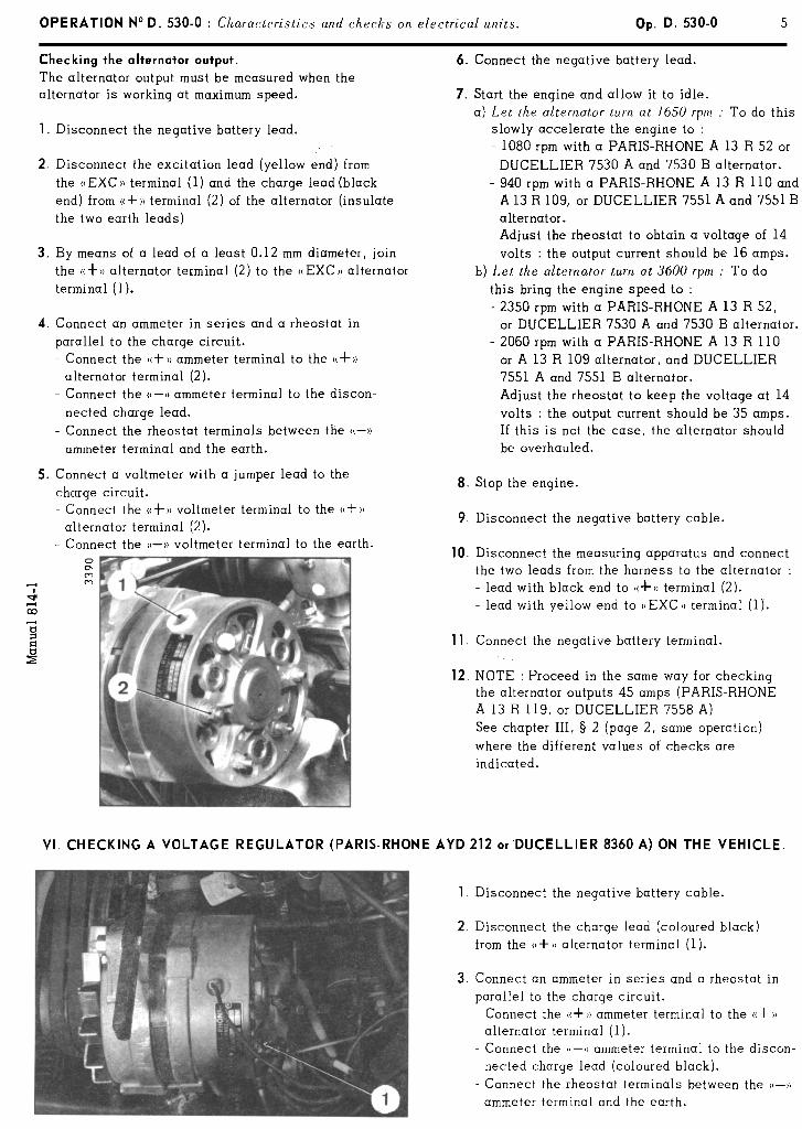
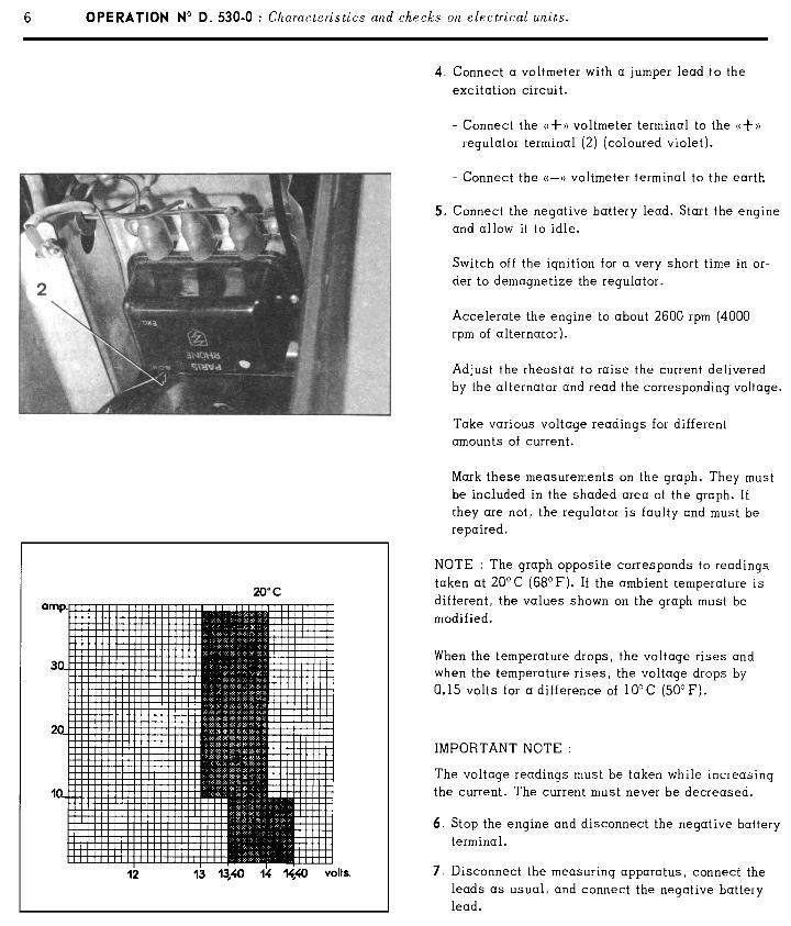
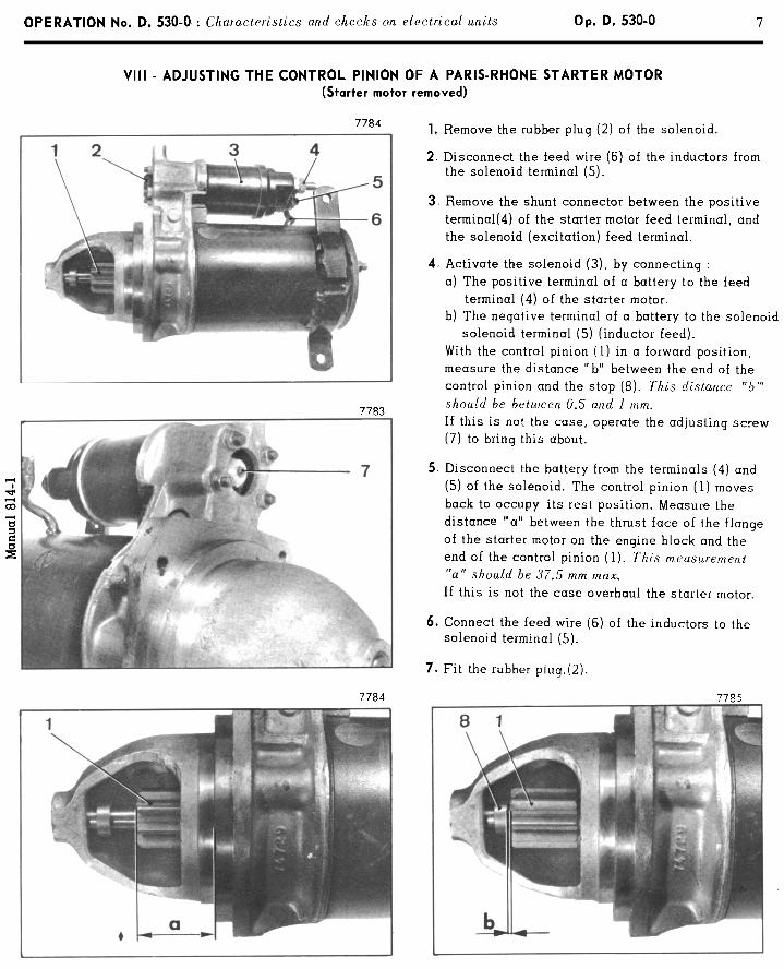

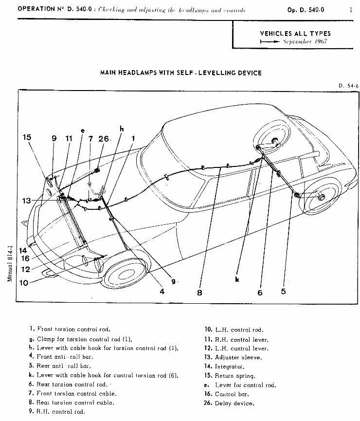
Op. D, 540.0
MAIN HEADLAMPS WITH SELF - LEVELLING DEVICE
1. Front torsion control rod.
g. Clamp for torsion control rod (1).
h. Lever with cable hook for torsion control rod (1).
4. Front anti-roll bar.
5. Rear anti -roll bar.
k. Lever with cable hook for control torsion rod (6).
6. Rear torsion control rod.
7. Front torsion control cable.
8. Rear torsion control cable.
9, R.H. control rod.
10. L.H. control rod.
11. R.H. control lever.
12. L.H. control lever.
13. Adjuster sleeve.
14. Integrator.
15, Return spring.
e. Lever for control rod.
16. Control bar.
26. Delay device.
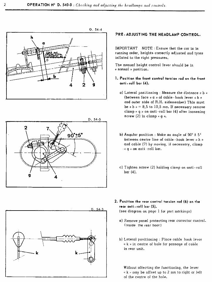
2 OPERATION No D. 54@-0 : Ch /.’ cc ung and adjusting the headlamps and controls.
D. 54-4 I I PRE-ADJUSTING THE HEADLAMP CONTROL.
IMPORTANT NOTE : Ensure that the car is in running order, heights correctly adjusted and tyres inflated to the right pressures.
The manual height control lever should be in (( normal )) position.
1. Position the front control torsion rod on the front
anti -roll bar (4).
a) Lateral positioning : Measure the distance (( b u
(between face C( a )) of cable- hook lever (( h )) and outer side of R.H. sidemember) This must be (( b 1) = 8,5 to 10,s mm. If necessary remove clamp C! g )) on anti -roll bar (4) after loosening screw (2) in clamp (( g )).
b) Angular position : Make an angle of 90’ + 5’
between centre line of cable-hook lever (( h H and cable (7) by moving, if necessary, clamp (( g )) on anti-roll bar.
c) Tighten screw (2) holding clamp on anti-roll
bar (4).
2. Position the rear control torsion rod (6) on the
rear anti -roll bar (5).
~ (see diagram on page 1 for part markings)
I a) Remove panel protecting rear corrector control. ( inside the rear boot )
b) Lateral positioning : Place cable hook lever (( k )) in centre of hole for passage of cable in rear unit.
Without affecting the functioning, the lever (C k u may be offset up to 2 mm to right or left of the centre of the hole.
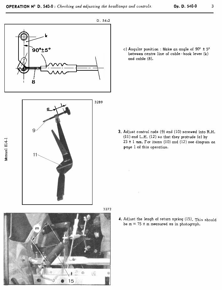
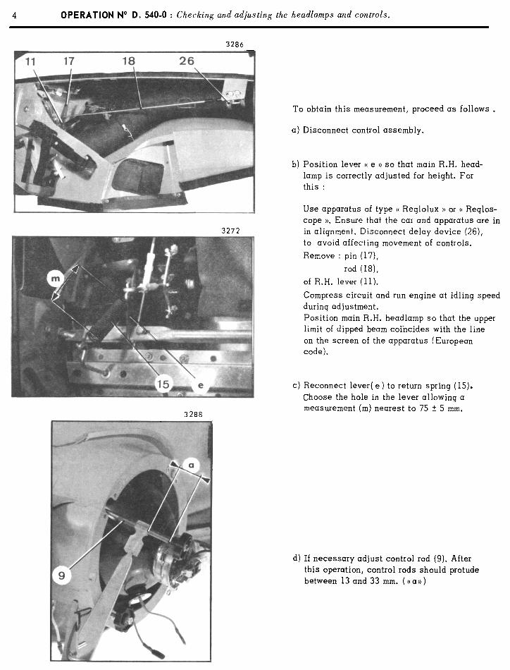
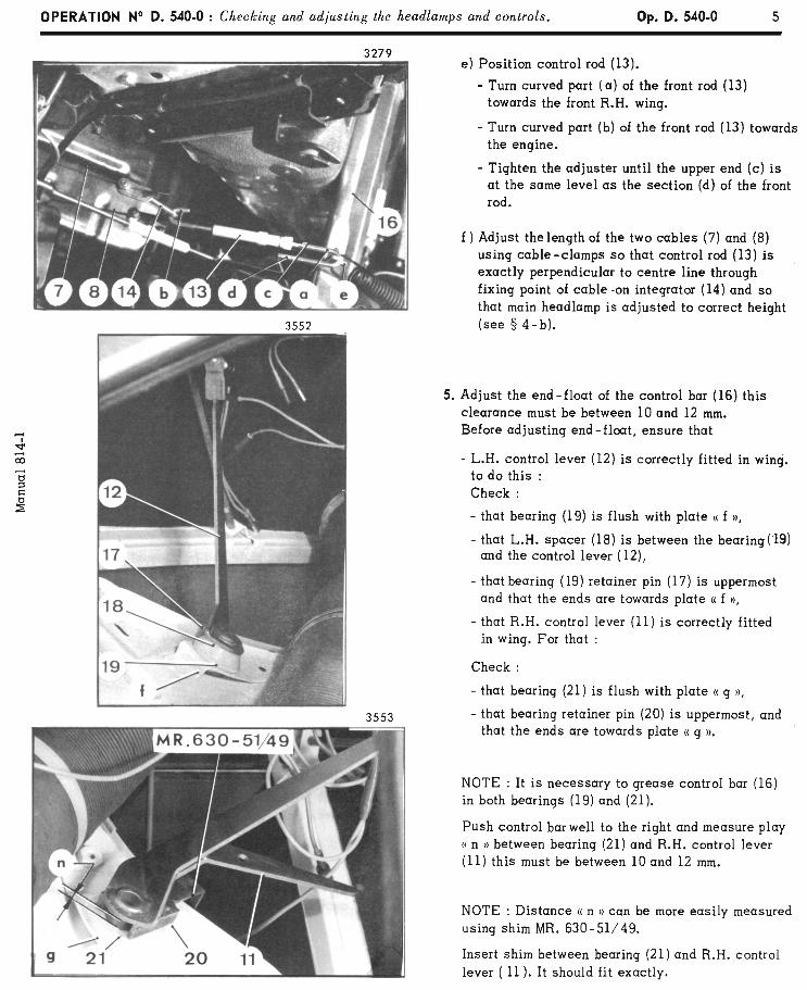
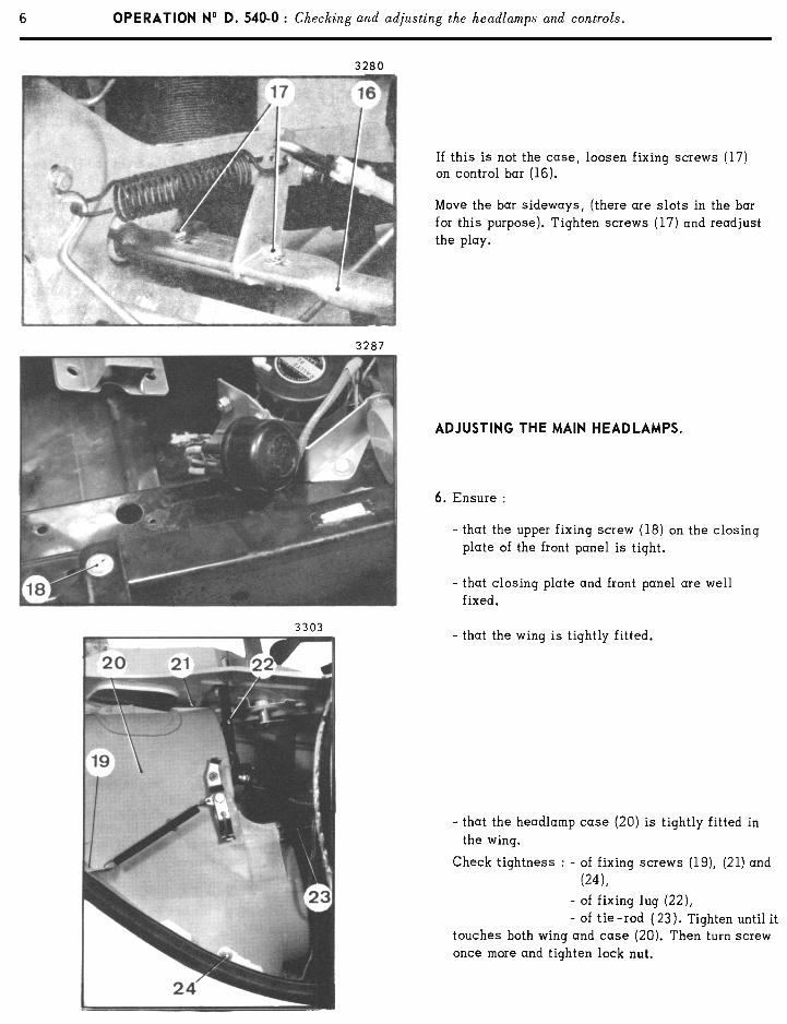
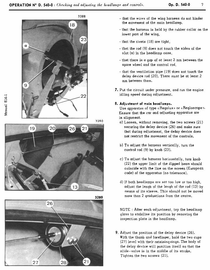
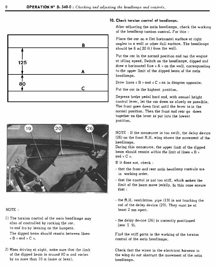
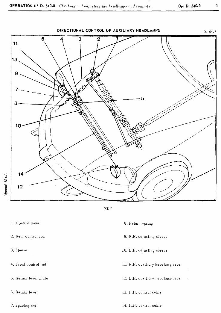
OPERATION No D. 540-O : Ch lz’ ec lng und adjusting the hendlumps und c:ontrols. Op. D. 540.0 9
DIRECTIONAL CONTROL OF AUXILIARY HEADLAMPS D. 54.7
1; Control lever
2. Rear control :od
3. Sleeve
4. Front control rod
5. Return lever plate
KEY
8. Return spring
9. R.H. adjusting sleeve
10. L.H. adjusting sleeve
11. R.H. auxiliary headlamp lever
12. L.H. auxiliary headlamp lever
6. Return lever
7. Spacing rod
13. R.H. control cable
14. L.H. controi cable
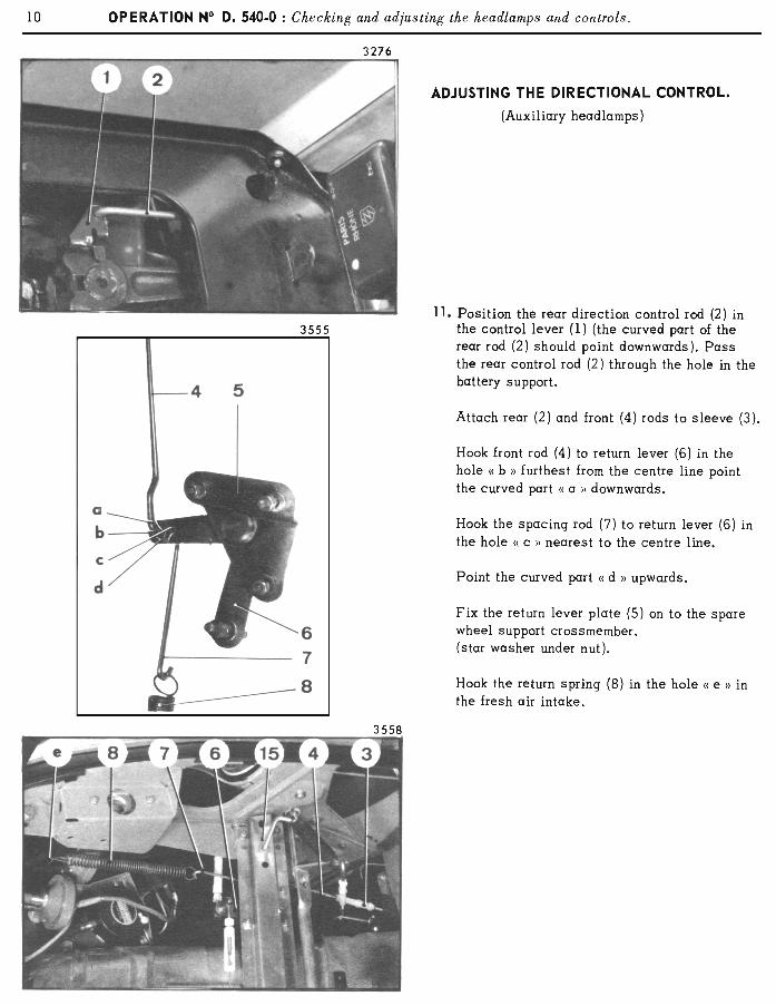
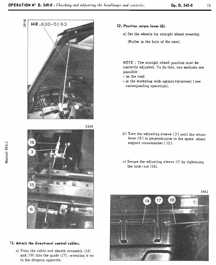
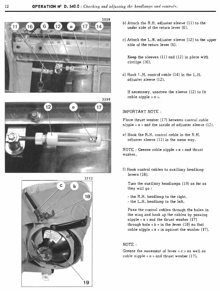

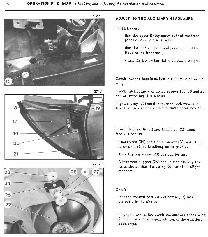

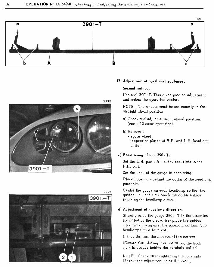

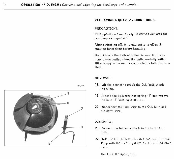
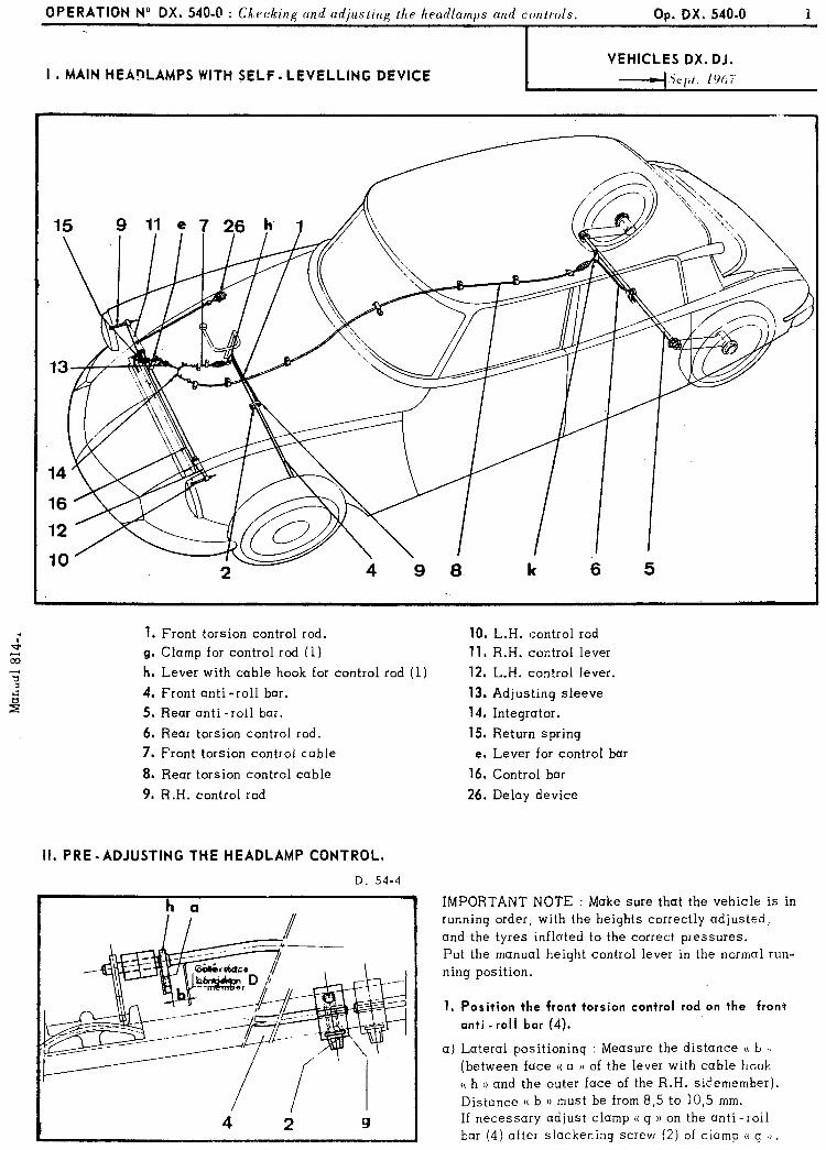
OPERATION No DX. 540-O : CX. .k’ PC ing and adjusting the headlamps and controls.
I
Op. DX. 540.0
I. MAIN HEADLAMPS WITH SELF- LEVELLING DEVICE VEHICLES DX. DJ.
-+cpt. IOh
1. Front torsion control rod.
g. Clamp for control rod (1)
h. Lever with cable hook for control rod (1)
4. Front anti -roll bar.
5, Rear anti-roll bar.
6. Rear torsion control rod.
7. Front torsion control cable
8. Rear torsion control cable
9. R.H. control rod
10. L.H. control rod
11. R.H. control lever
12. L.H. control lever.
13. Adjusting sleeve
14. Integrator.
15. Return spring
e. Lever for control bar
16. Control bar
26. Delay device
II. PRE -ADJUSTING THE HEADLAMP CONTROL.
D. 54.4
h a IMPORTANT NOTE : Make sure that the vehicle is in running order, with the heights correctly adjusted, and the tyres inflated to the correct pressures. Put the manual height control lever in the normal run-
ning position.
1. Position the front torsion control rod on the front anti -roll bar (4).
a) Lateral positioning : Measure the distance 5~ b II (between face (( a )) of the lever with cable hook (( h 1) and the outer face of the R.H. sidemember). Distance (( b I) must be from 8,5 to 10,s mm. If necessary adjust clamp u g )) on the anti-roll bar (4) after slackening screw (2) of clamp (( g 1).
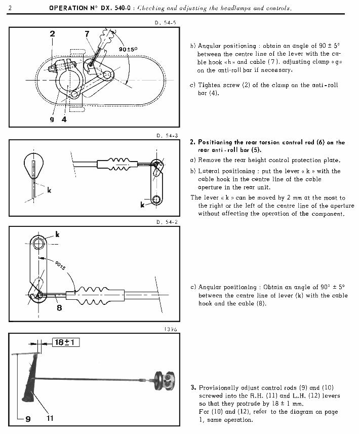
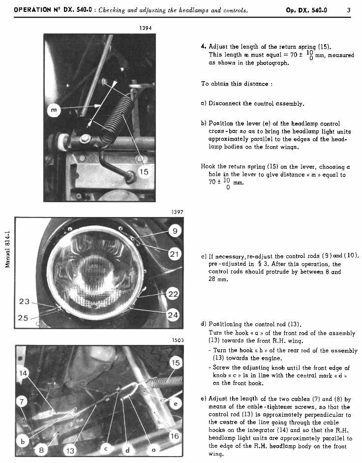
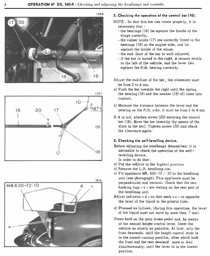
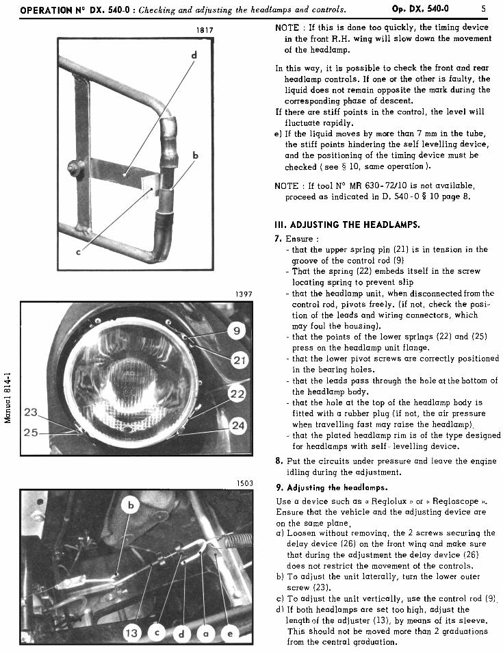
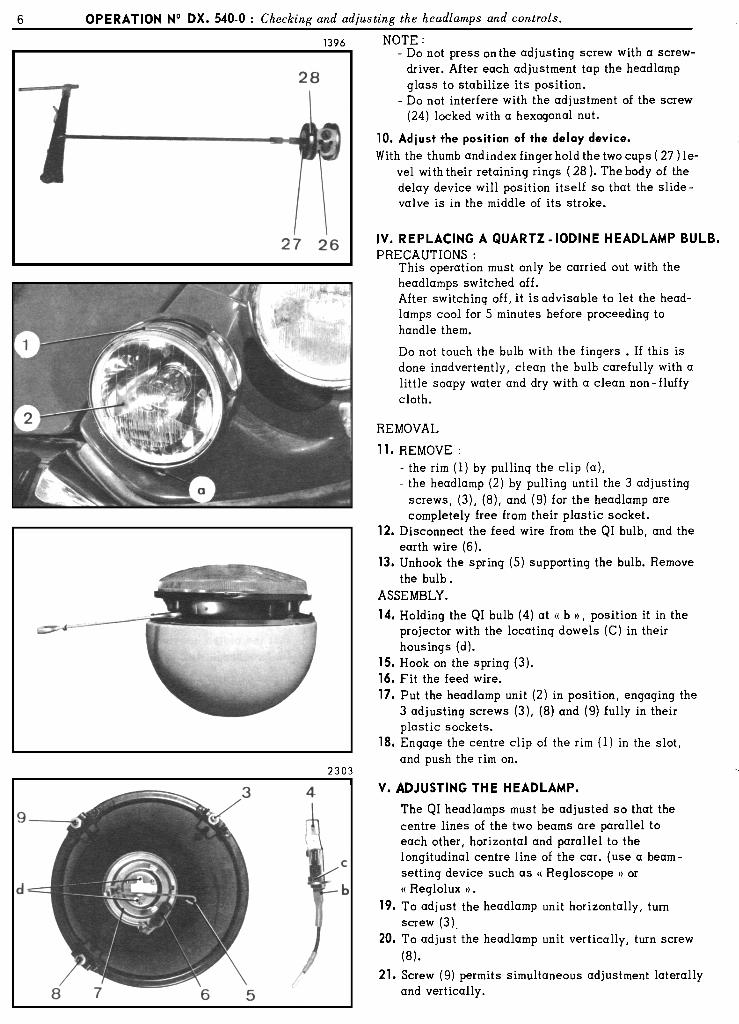
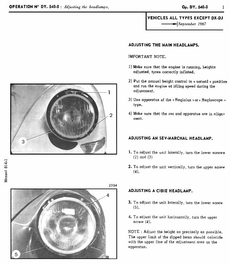
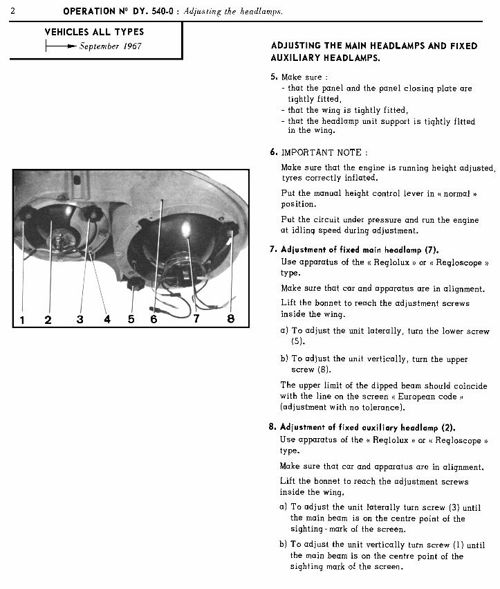
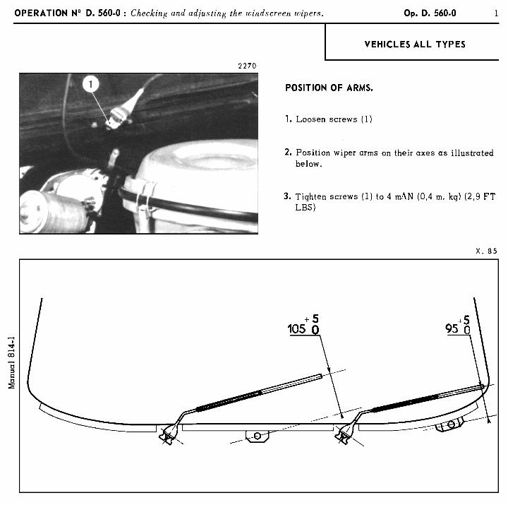
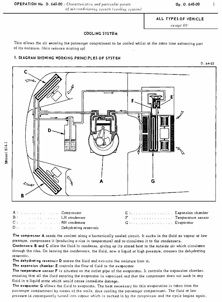
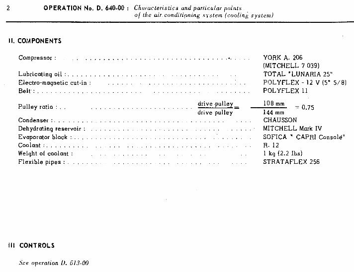
2 OPERATION No. D. 640-00 : Chclracteristics and particular points of lhe air conditipning sj.stem (coolinK system)
I I. COMPONENTS
Compressor : . . . . ,
Lubricating oil : . , . . . . . . Electra-magnetic cut-in : Belt, : . . . . . . . . . . .
. . . . . . . . . . . . . . . . . . . . . . . . . . .*...
.,.... ,,..... ,.,..... .,..
Pulley ratio : . .., . . . . . . . . . . . . . .
Condenser : . . . . . . Dehydrating reservoir : Evaporator block :, Coolant : . . . . , . Weight of coolant : Flexible pipes : .
. .
. drive .pulley= drive pulley
,,...,. ..,....
YORK A. 206 (MITCHELL 7 039) TOTAL ’ LUNARIA 25” POLYFLEX - 12 V (5” 5/8) POLYFLEX 11
108 mm 144 mm
= 0.75
CHAUSSON MITCHELL Murk IV SOFICA 1 CAPRI Consold”
. . . . . . . . . . I R. 12 1 kg (2.2 Ibs)
. . STRATAFLEX 256
III CONTROLS
See operation I). ti13-00
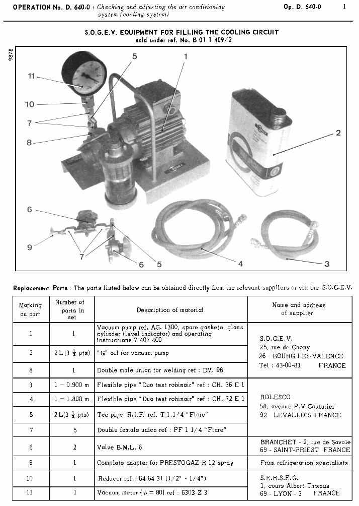
IMPORTANT MOTE
The operating instructions (ref. 7 407 400) supplied with the S.O.G.E.V. vacuum pump must be consulted before
starting up the latter, and for motters concerning its maintenance and repair.
The incorrect connecting up of the eiectric motor, or starting the vacuum pump without “G” oil would bring about
rapid deterioration of the components.
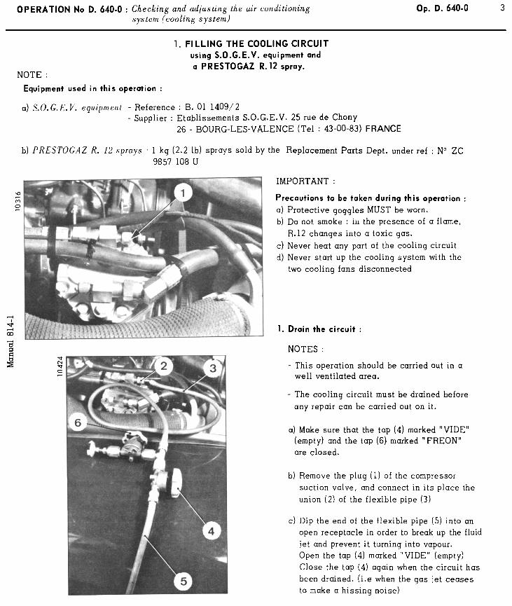
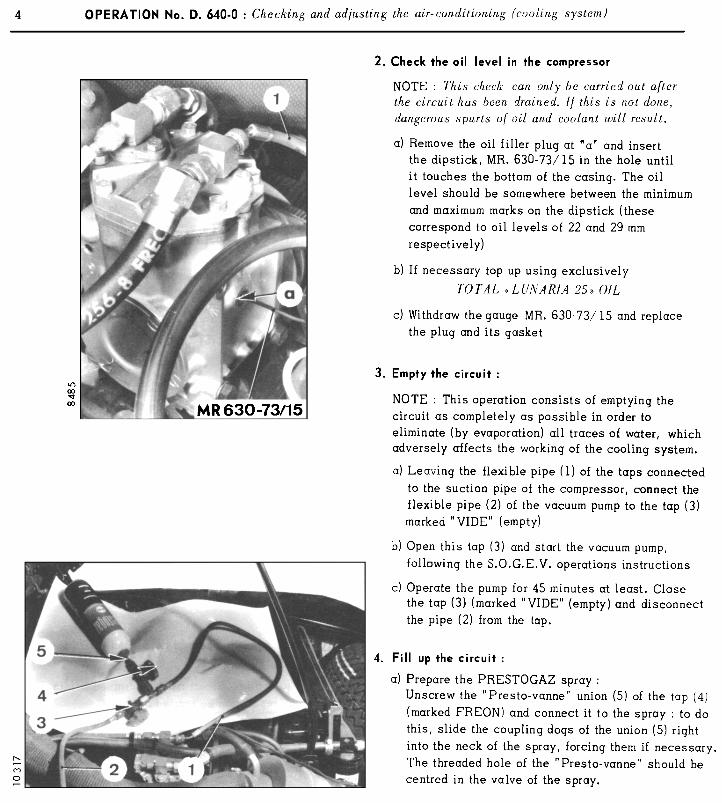
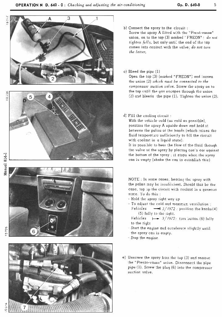
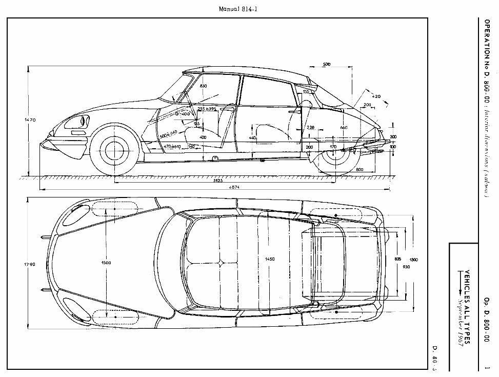
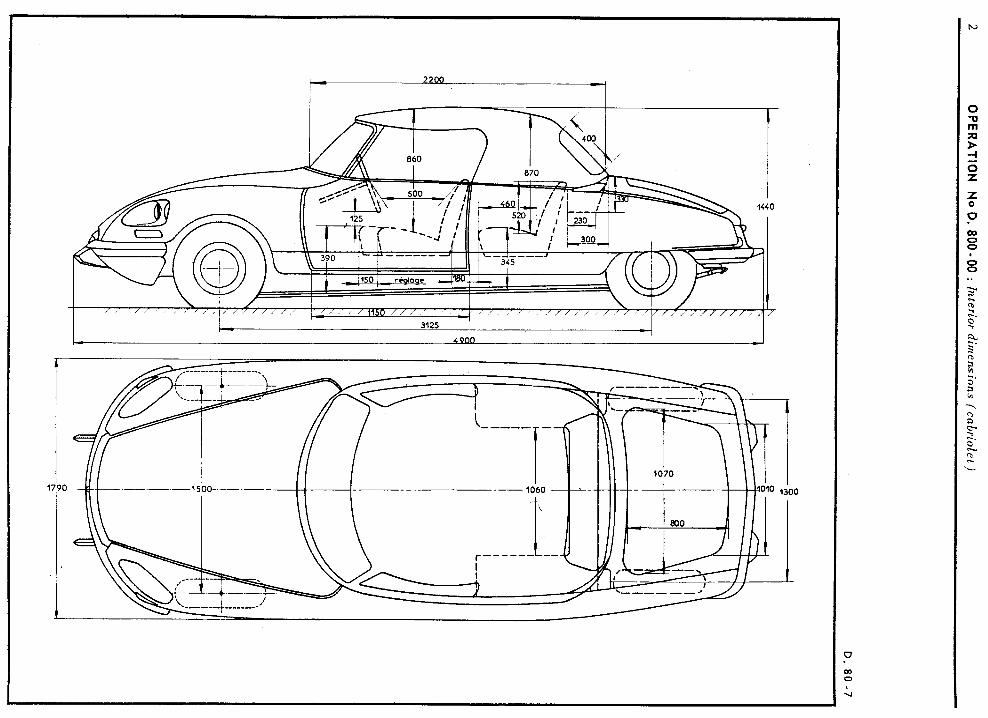
2 O
PERATIO
N
NO D
. 800-00
: Interior
dimensinns
(cabriolet)
D. 80
-7
, I I I I
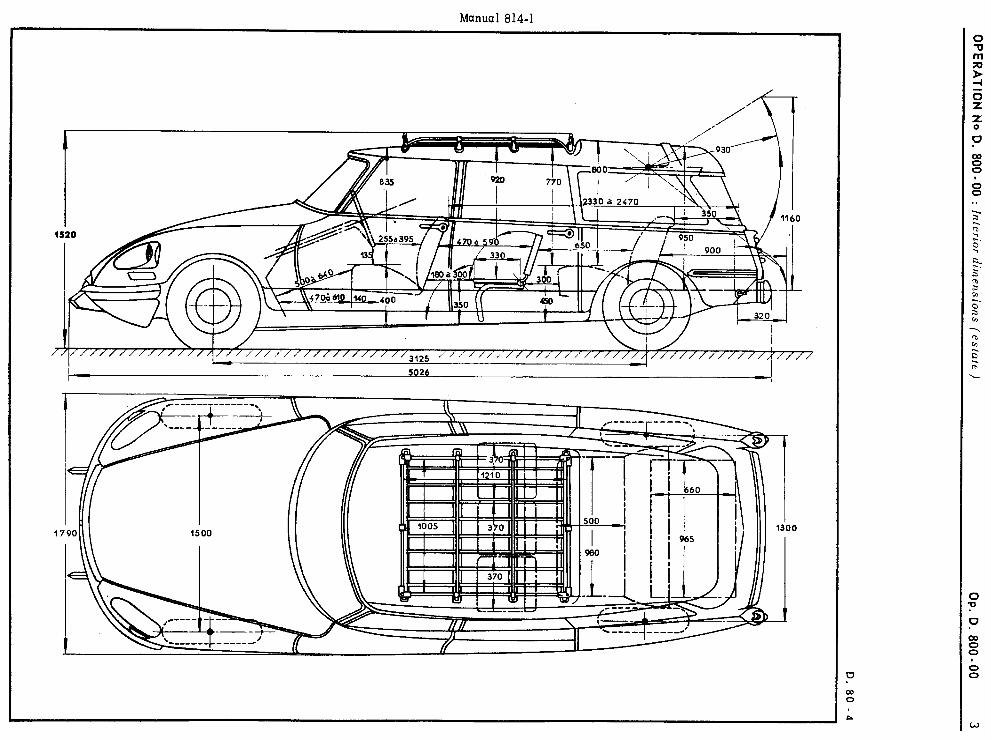
OPER
ATION
N
o D.
800-00 :I n
erior dim
ensions (estale
) I
OP
. D. 800-00
3
D.80 -4
\ \ \ \ \ \ \ \ \ \ \ \ \ \ \ \ \ \ \ \ ‘\ Y
5 b \ \ \ \ \ \ \ \ \ \ \ \ 1%
\ \
,-I’ 2
: ;,
I-- *--S-l
; -\
I I
-- ----e---
~~ ~~
I :
\ I,-
-------- J
I
! 1
,+
:
m-e- ----
f
--I
i
I
‘, ;
1
a-ga’-;
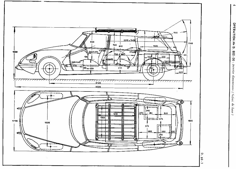
4 O
PERATION
No D
. 800-00
: lnlerior
dimensions
( ,Scl/;tri
de llixe
)
D.
80-3
\ \ \ \ \ \ \, \ 1 \ \ \ \ \ \ \ \ \ \ \ \ \ \ \ \ \ \ \ \ \ \ \ 1: 1: \ \ \ \ \ \ \ \ \ \ \ \ \ \ \ \
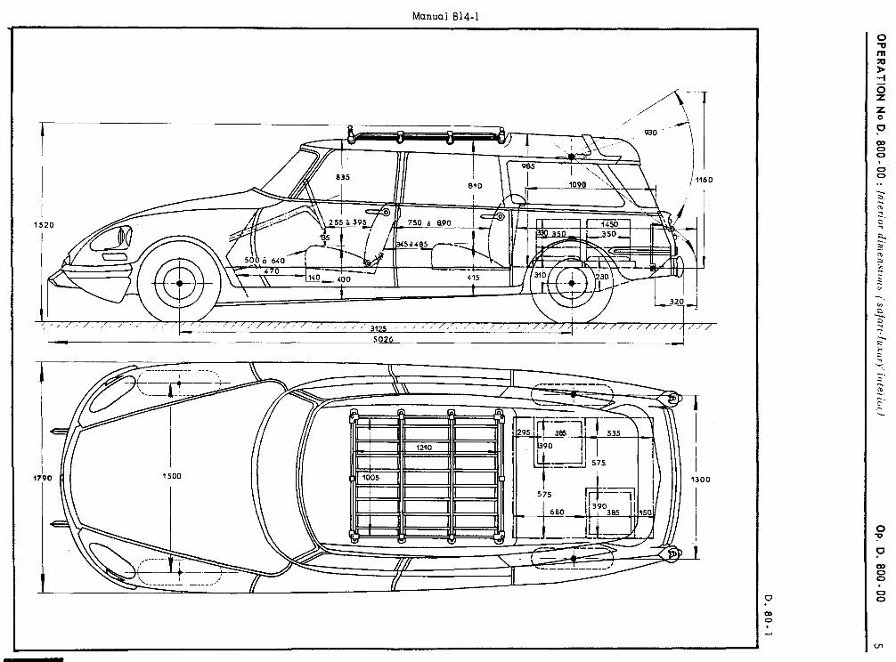
OPERATIO
N No
D. 800.00
: Interior
dimensions
~safnri-fuxur)-‘inteiiclrl O
p. D
. 800-00
5
D. 80-
1
\I N .M
II
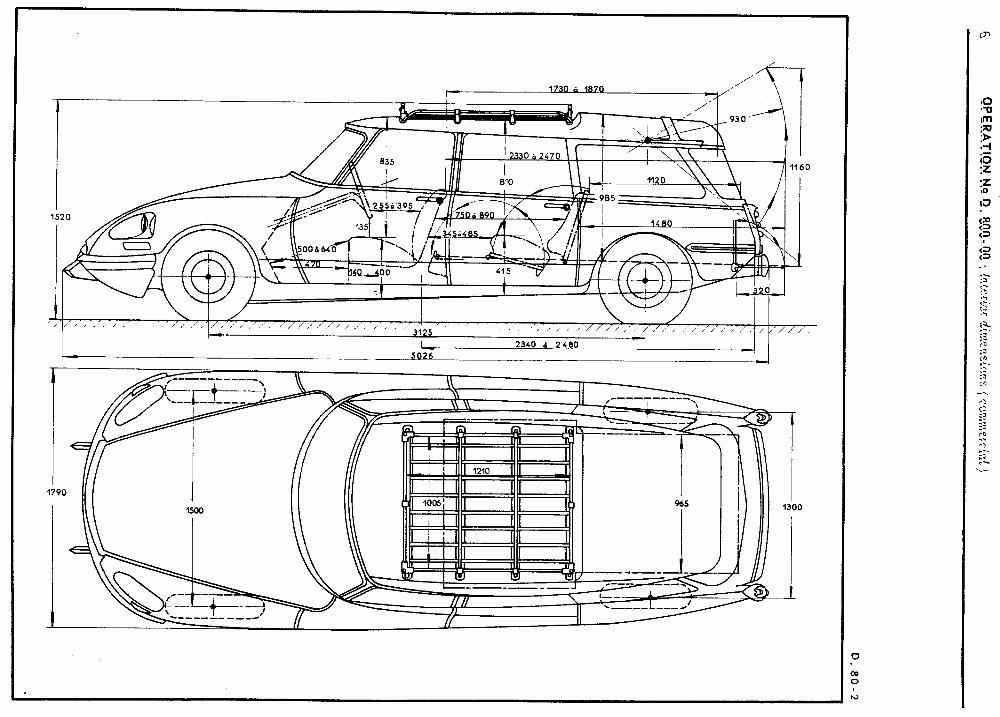
6 O
PERATIO
N
NO D
. 800 - 00
: Interior
dimensions
(comm
ercial)
D. 80-2
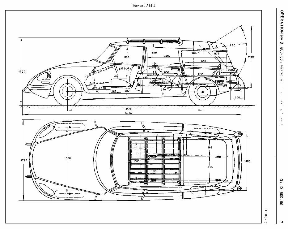
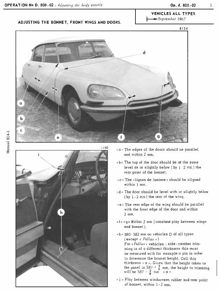
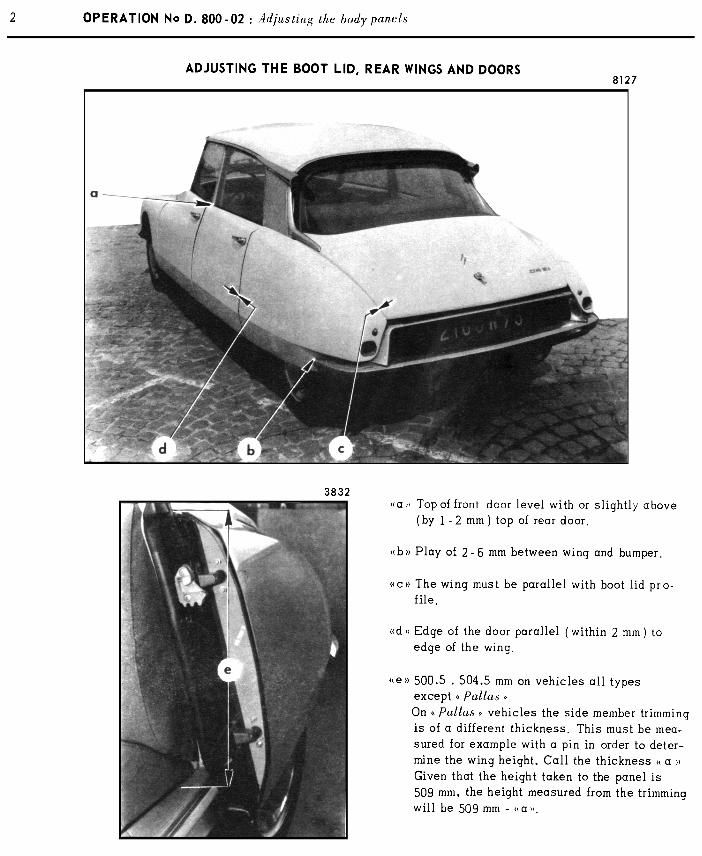
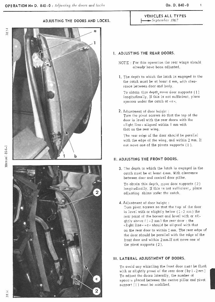
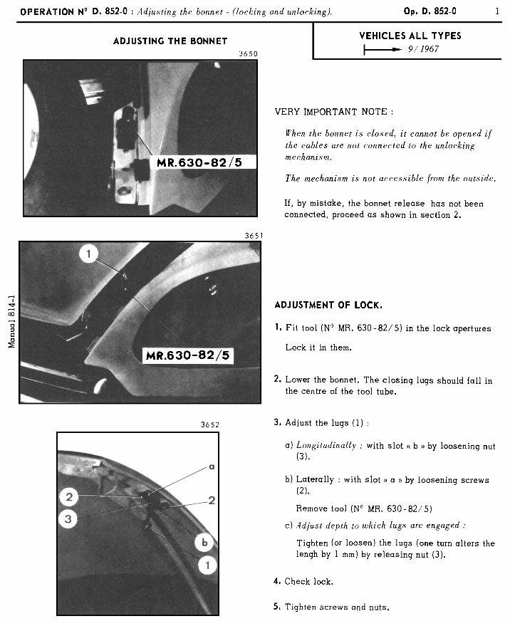
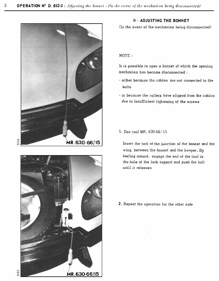

OPERATION N“ 0. 961-O : Ch IL’ cc ~ng rind relmiring I)/ (1 Ilenlcsd war uindou Op. D. 961-O I
CHECKING AND REPAIRING OF A REAR WINDOW HEATING RESISTANCE.
I. CHECKING
Force of the heating resistonce :
a) Sa1001~ : 4 6 197:‘. .......................... 73 to a4 Watts under 13,5 + 0.2 volts
I--- h/i972 ........................... 95 to 110 Watts under 13.5 + 0.2 volts
b)Snlnri: ........................................... 85 to 110 Watts under 13.5 + 0.2 volts
TO check the rear window heating resistance, measure : 1. Ither the current circulating in the resistance, by using a amphemeter, connected to the feed resistance wire.
The current should be for : a) Snl0071 --Y 6,‘1971. . . . . . . , . , . . . . . . . . . . . . . . . . . .4.8 to 5.3 amps under 12 volts
I-- 6 / 1972. . . . . . . . . . . . . . . . , . . . . . . . . . . .6.2 to 7.2 amps under 12 volts b) .Sa/ari : . . . . . . . . . . . . . . . . . . . . . . . . , . . . . . . . . . . . . . . . . .5.6 to 7.2 amps under 12 volts
2. Ither the resistance, using a ohmmeter. The resistance should be : a) 5~1100t~ --+ 6!197P.. . . . . . . . . . . . . . . . . . . . . . . . . . .2.17 to 2.5 R
I---- o 1972. . . . . . . . . . . . . , . . _ , . . . . . . . . . .1.65 to 1.92 !2 b) Sn/ari:........................................ .1.65 to 2.14 !I
F-i 4 A a3
‘;; 2 54
II. REPAIRS.
NOTE : The two undementioned repairs can be carried out on a heated window fitted to the vehicle.
1. Replacing the terminals.
Tin the part o: the terminal to be soldered. Solder it in the place provided (soldering iron).
2. Repairing on element.
a) Obtain from the Replacement Parts Department : - 1 Kit . . . . . , . . . . . . . . , . . , . . . . . . . . . . . . . . . . . . . . . . . .ZC. 9 855 128 U This kit “SECURIGLACE” contains : - 1 Bottle of abrasive cleaning powder, - 1 Sachet of conducting enamel, - 1 Tube of adhesive - 1 Tube of hardening product for the adhesive, - 1 Bottle of metallic powder, - 1 Roll of thick adhesive tape, - 1 Warning light for detecting cuts,
- 1 Roll of adhesive for detecting cuts, - 1 -Plastic spatula, - 1 Glass plate, for mixing the products,
b b) Locating the cut :
With resistance fed as normal :
- Locate the defective resisting wire by sticking the adhesive detecting tape in the centre of the rear window (on the inside), and on all the resistance lines so that the tape is perpendicular to the latter. The wires, whe when the circuit is not broken, will turn the thermopaper blue when the temperature generated is raised.
- Onto the cut wire, slide the two pointed probes of the support of the warninq light, used for detecting cuts. When the lamp lights up, the pointed probes are on both sides of the break in the resistance. By moving them slightly along the wire, one can determine the extent of the cut exactly.
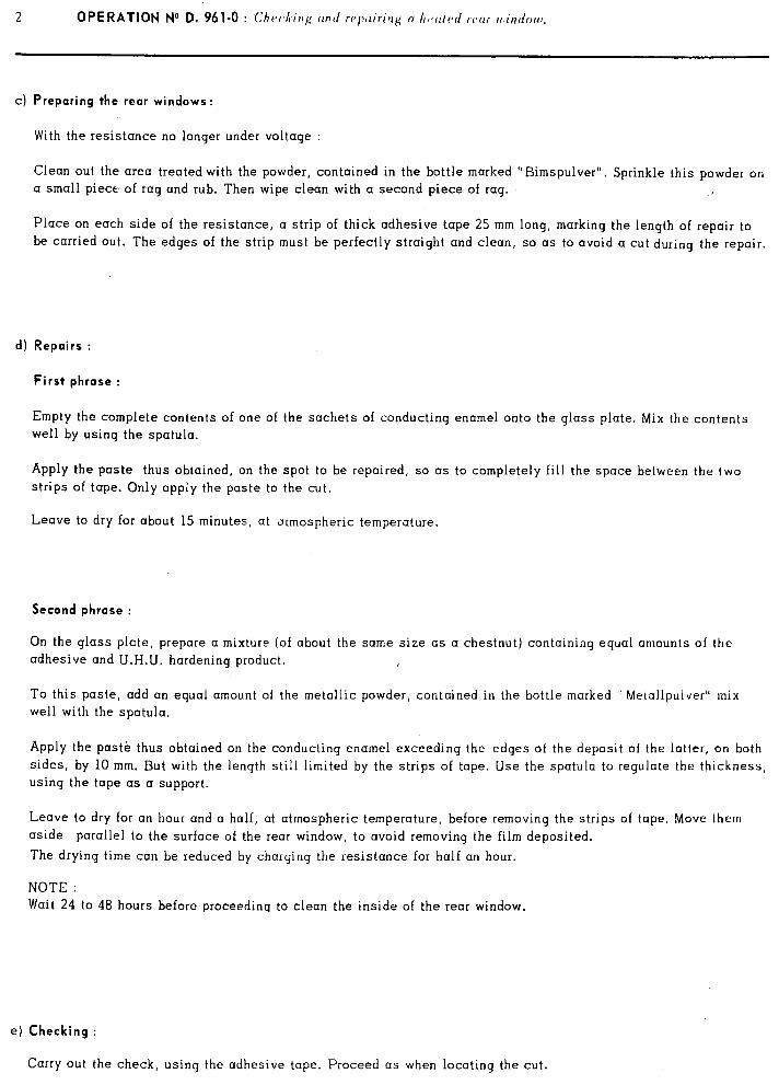
c) Preparing the rear windows:
With the resistance no longer under voltage :
Clean out. the area treated with the powder, contained in the bottle marked “Bimspulver”. Sprinkle this powder on a small piece of rag and rub. Then wipe clean with a second piece of rag.
Place on each side of the resistance, a strip of thick adhesive tape 25 mm long, marking the length of repair to be carried out. The edges of the strip must be perfectly straight and clean, so as to avoid a cut during the repair.
d) Repairs :
First phrase :
Empty the complete contents of one of the sachets of conducting enamel onto the glass plate. Mix the contents
well by using the spatula.
Apply the paste thus obtained, on the spot to be repaired, so as to completely fill the space between the two strips of tape. Only apply the paste to the cut.
Leave to dry for about 15 minutes, at ormospheric temperature.
Second phrase :
On the glass plate, prepare a mixture (of about the same size as a chestnut) containing equal amounts of the adhesive and U.H.tJ. hardening product.
To this paste, add an equal amount of the metallic powder, contained in the bottle marked ” Metallpulver” mix well with the spatula,
Apply the paste thus obtained on the conducting enamel exceeding the edges of the deposit of the latter, on both sides, by 10 mm. But with the length still limited by the strips of tape. Use the spatula to regulate the thickness,
using the tape as a support.
Leave to dry for an hour and a half, at atmospheric temperature, before removing the strips of tape. Move them
aside parallel to the surface of the rear window, to avoid removing the film deposited.
The drying time can be reduced by charging the resistance for half an hour.
NOTE : Wait 24 to 48 hours before proceeding to clean the inside of the rear window.
e) Checking :
Carry out the check, using the adhesive tape. Proceed as when locating the cut.
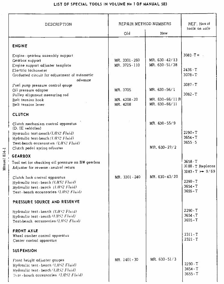
LIST OF SPECIAL TOOLS IN VOLUME No 1 OF MANUAL 583
DESCRIPTION
ENGINE
Engine -gearbox assembly support Gearbox support Engine support adjuster template Electric tachometer Grcduated circuit for adjustment of automatic
advance
Fuel pump pressure control gauge Oil pressure adapter Pulley alignment measuring rod Belt tension hook Belt tension lever
CLUTCH
Clutch mechanism control apparatus (D. IE vehicles)
Hyaraulic test-bench{/.//.%? Fluid) Hydraulic test-bench /‘I. /IS2 I:/uidl Test-bench accessories (l,Ilil! h’luid) Clutch pedal spring adjuster
GEARBOX
Tool set for checking oil pressure on BW gearbox Adjuster for reverse -neutral return
Clutch lock control apparatus Hydraulic test - bench (I.//.i’? b’lrritf) Hydraulic test - bench (I,//.$:’ /:luid) Test - bench accessories f/./l?;:’ Fluid)
PRESSURE SOURCE AND RESERVE
Hydraulic test-bench (LIISL’ Fltritll Hydraulic test -bench lI,!l.$L’ l:luid) Test-bench accessories (/.1/4‘L’ Fluid)
FRONT AXLE Wheel camber control apparatus Caster control apparatus
SUSPENSION
Front height adjuster gauges
Hydraulic test -bench f’l,llSL’ l:lnid) Hydraulic test-bench ~l,ll.52 b’lrcitll Test -bench accessories /l.//.‘i? Fluid)
REPAIR METHOD NUMBERS
Old
MR. 3301- 260 MR. 3725 - 110
MR. 3705
MR. 4208 - 20 MR. 4208
MR. 330
MR. 140
‘1 - 240
- 30
New
MR. 630-42/13 MR. 630-51/38
MR. 630 - 56/ 1
MR. 630-66/11 E MR. 630 - 66/ 11
MR. 630 - 55/ 9
MR. 630- 27/2
MR. 630”43/ 20
MR. 630-51/3
REF. Nosof tools on sale
1083 -T a
!436 - T 1078-T
1087 - T
1082 -T
!290- T 3654-T 3655 - 5
3658 - T 3188 - T Replace:
3183-T ~-r 9,/69
2290 - T
3654-T 3655-T
2290-T 3654 -,T 3655 - T
2311-T 2321- T
2290-T 3654-T
3655 - T
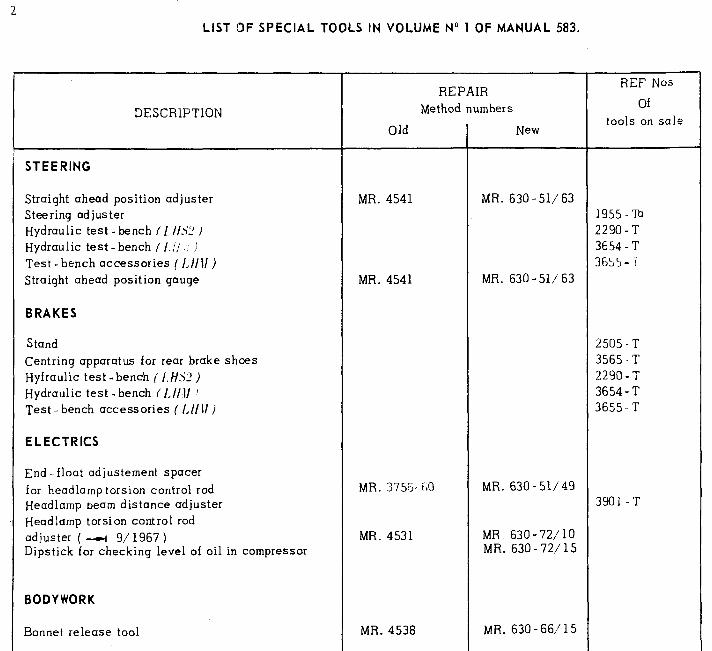
2 LIST OF SPECIAL TOOLS IN VOLUME No 1 OF MANUAL 583.
DESCRIPTION
STEERING
Straight ahead position adjuster Steering adjuster
Hydraulic test -bench (I I/L! ) Hydraulic test-bench ( /,;j I Test -bench accessories ( I,}/11 ) Straight ahead position gauge
BRAKES
Stand
Centring apparatus for rear brake shoes Hyfraulic test -bench ( /.HL! ) Hydraulic test -bench (1,1/l/ : Test-bench accessories ( 1.11 II )
ELECTRICS
End -float adjustement spacer
for headlamp torsion control rod Headlamp beam distance adjuster
Headlamp torsion control rod adjuster ( -WI 9/ 1967 ) Dipstick for checking level of oil in compressor
BODYWORK
Bonnet release tool
Old
REPAIR
Method numbers
New
MR. 4541
MR. 4541
MR. 3753- iLl
MR. 4531
MR. 4538
MR. 630-51/63
MR. 630 - 51/ 63
MR. 630 - 51/49
MR. 630-72/10 MR. 630 - 72/ 15
MR. 630-661’15
REF Nos
Of
tools on sale
1955 - To 2290-T 3654 -T 3655 - 7
2505 -T 3565 -T 2290 -T 3654 - T 3655. T
3901 -T