city of winnipegwinnipeg.ca/finance/findata/matmgt/documents//2015/339-2015//339... · city of...
TRANSCRIPT
City of Winnipeg Addition to Fire Hall # 6 at 603 Redwood Ave July 2014 Geotechnical Investigation and Foundation Assessment KGS 14-0107-006
Standard Penetration Tests (SPT) were conducted in the underlying silt till layer to determine the relative density of the till. Upon completion of the drilling, the test holes were examined for indications of squeezing and seepage and then backfilled with auger cuttings and bentonite chips.
A laboratory testing program was undertaken, which included 29 moisture content analyses and two (2) Atterberg Limits tests. The results are shown on the detailed test hole logs attached in Appendix B.
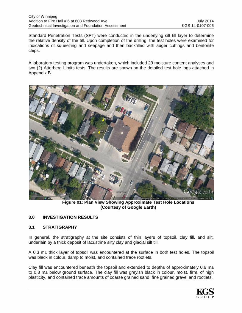
Figure 01: Plan View Showing Approximate Test Hole Locations
(Courtesy of Google Earth) 3.0 INVESTIGATION RESULTS 3.1 STRATIGRAPHY In general, the stratigraphy at the site consists of thin layers of topsoil, clay fill, and silt, underlain by a thick deposit of lacustrine silty clay and glacial silt till. A 0.3 m± thick layer of topsoil was encountered at the surface in both test holes. The topsoil was black in colour, damp to moist, and contained trace rootlets. Clay fill was encountered beneath the topsoil and extended to depths of approximately 0.6 m± to 0.8 m± below ground surface. The clay fill was greyish black in colour, moist, firm, of high plasticity, and contained trace amounts of coarse grained sand, fine grained gravel and rootlets.

City of Winnipeg Addition to Fire Hall # 6 at 603 Redwood Ave July 2014 Geotechnical Investigation and Foundation Assessment KGS 14-0107-006
A 0.4 m to 0.6 m thick layer of silt was encountered beneath the clay fill and extended to approximately 1.2 m± below ground surface. The silt was tan in colour, moist, soft and of low plasticity. Underlying the silt was a layer of silty clay of lacustrine origin which extended to approximately 11.4 m± and 11.3 m± below existing ground surface in TH14-01 and TH14-02 respectively. The silty clay was brown mottled grey in colour and became grey below 6.7 m to 6.9 m depth, soft to stiff, moist, of high plasticity, and contained trace amounts of silt nodules and oxidation. Moisture contents of the clay ranged from 33% to 59% with an overall average of 49%. Based on two Atterberg limits tests, the plastic limits, wp, ranged from 17% to 28%, liquid limits, wl ranged from 61% to 97%, and Plasticity Indices, Ip, ranged from 43% to 70%, resulting in a classification of CH for the clay based upon the modified Unified Soil Classification System (USCS). The undrained shear strength, as estimated from the field Torvane, ranged from 13 kPa to 100 kPa, with higher shear strengths measured near the top of the layer and decreased with depth. Underlying the silty clay was a deposit of glacial silt till that extended to power auger refusal at a depth of 13.7 m± and 13.6 m± in TH14-01 and TH14-02 respectively. The silt till was tan in colour, damp to moist, compact to dense, and contained some fine to coarse grained sand and trace amounts of fine grained gravel. Uncorrected blow counts (Nuncorrected) of 34 and 9 were recorded from an SPT in TH14-01 and TH14-02 respectively at a depth of 12.2 m±. SPT refusal criteria was encountered in both TH14-01 and TH14-02 below 13.0 m± with blow counts greater than 50 blows per 0.15 m (6 inches). 3.2 GROUNDWATER CONDITIONS Upon completion of drilling, water infiltration into the test hole was noted from the silt till and the water level was at 12.8 m± and 11.6 m± below existing grade in TH14-01 and TH14-02 respectively. Groundwater levels are known to fluctuate seasonally and annually in response to such occurrences such as rainfall events and snowmelt. The groundwater level at the time of construction may differ from that reported herein. 4.0 BUILDING FOUNDATION OPTIONS Shallow foundations are not typically used in Winnipeg for lightly loaded structures due to the expansive nature of the soils in the City. Shallow foundation have potential for settlement, both total and differential, which are typically unacceptable for most structures, and makes deep foundations the preferred option to support lightly loaded structures in Winnipeg. Additionally, the existing fire hall is founded on cast-in-place concrete piles and potential differential settlement between the proposed addition and the existing fire hall can lead to structural concerns at the building joints. Suitable deep foundation types for consideration include cast-in-place concrete piles or driven pre-cast concrete piles. Cast-in-place concrete friction piles are recommended to be consistent with the existing fire hall for similar performance.
City of Winnipeg Addition to Fire Hall # 6 at 603 Redwood Ave July 2014 Geotechnical Investigation and Foundation Assessment KGS 14-0107-006
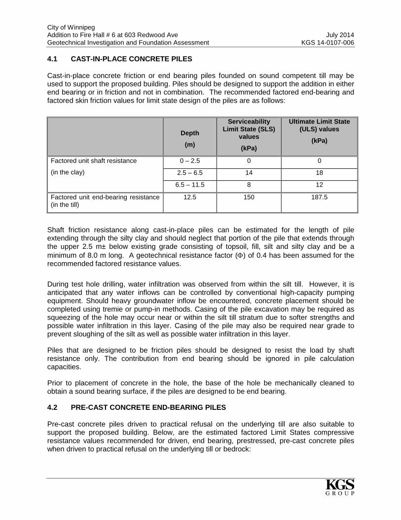
4.1 CAST-IN-PLACE CONCRETE PILES Cast-in-place concrete friction or end bearing piles founded on sound competent till may be used to support the proposed building. Piles should be designed to support the addition in either end bearing or in friction and not in combination. The recommended factored end-bearing and factored skin friction values for limit state design of the piles are as follows:
Depth
(m)
Serviceability Limit State (SLS)
values
(kPa)
Ultimate Limit State (ULS) values
(kPa)
Factored unit shaft resistance
(in the clay)
0 – 2.5 0 0
2.5 – 6.5 14 18
6.5 – 11.5 8 12
Factored unit end-bearing resistance (in the till)
12.5 150 187.5
Shaft friction resistance along cast-in-place piles can be estimated for the length of pile extending through the silty clay and should neglect that portion of the pile that extends through the upper 2.5 m± below existing grade consisting of topsoil, fill, silt and silty clay and be a minimum of 8.0 m long. A geotechnical resistance factor (Φ) of 0.4 has been assumed for the recommended factored resistance values.
During test hole drilling, water infiltration was observed from within the silt till. However, it is anticipated that any water inflows can be controlled by conventional high-capacity pumping equipment. Should heavy groundwater inflow be encountered, concrete placement should be completed using tremie or pump-in methods. Casing of the pile excavation may be required as squeezing of the hole may occur near or within the silt till stratum due to softer strengths and possible water infiltration in this layer. Casing of the pile may also be required near grade to prevent sloughing of the silt as well as possible water infiltration in this layer.
Piles that are designed to be friction piles should be designed to resist the load by shaft resistance only. The contribution from end bearing should be ignored in pile calculation capacities.
Prior to placement of concrete in the hole, the base of the hole be mechanically cleaned to obtain a sound bearing surface, if the piles are designed to be end bearing.
4.2 PRE-CAST CONCRETE END-BEARING PILES Pre-cast concrete piles driven to practical refusal on the underlying till are also suitable to support the proposed building. Below, are the estimated factored Limit States compressive resistance values recommended for driven, end bearing, prestressed, pre-cast concrete piles when driven to practical refusal on the underlying till or bedrock:

City of Winnipeg Addition to Fire Hall # 6 at 603 Redwood Ave July 2014 Geotechnical Investigation and Foundation Assessment KGS 14-0107-006
Pile Diameter Serviceability Limit State (SLS) value
(kN)
Ultimate Limit State (ULS) value
(kN)
300 mm diameter 445 560
350 mm diameter 625 785
400 mm diameter 800 960
A geotechnical resistance factor Φ of 0.4 has been assumed in estimating the factored resistances for compressive loading conditions.
To minimize the potential for rebound during pile driving the spacing between adjacent piles should be a minimum of three (3) pile diameters from centre to centre. Pre-boring a minimum of 4 m is recommended prior to driving the piles. The effect of ground vibration associated with driving piles near an existing building may make the driven pile option non-viable. 4.3 GENERAL PILE COMMENTS All piles should have a minimum length of 8 m with reinforcement over the full length of cast-in-place pile and a minimum 150 mm void form should be installed below all grade beams and pile caps to protect against potential uplift. Full-time inspection by experienced geotechnical personnel during construction of the piles is recommended. It is recommended that all concrete foundations in contact with native soils utilize sulfate resistant cement CSA Type HS. Where Pile Driving Analysis (PDA) Testing is undertaken on a minimum of 5% of the piles driven at the site, an increased geotechnical resistance factor (Φ) of 0.5 could be utilized on the pile resistance as determined by CAPWAP and field results. A geotechnical resistance factor (Φ) of 0.6 could be utilized on pile resistance if a static load test is undertaken on a minimum of two piles at the site. If either PDA testing or static load testing is undertaken, they should be completed under the supervision of an experienced geotechnical engineer and KGS Group should review the results of any testing and pile capacities. KGS Group recommends that the PDA testing followed by CAPWAP analysis be completed initially for the first 3 to 5 piles driven on site at the start of construction to confirm the ULS values and to allow for a geotechnical resistance factor of Φ = 0.5 to be applied to final design. KGS Group can arrange this testing to be completed on your behalf. 4.4 FLOOR SLAB CONSIDERATION The floor of the addition should consist of a structural floor slab supported on intermediate piles. A minimum 150 mm void space and / or a vented and heated crawlspace is recommended immediately below the structural floor to minimize potential heave due to possible swelling of the underlying clay soils. The subgrade should be prepared by stripping all deleterious materials and grading the subgrade towards the sub-floor drainage system. Where a crawlspace is used, the base of the crawlspace should be covered with vapour barrier and a 100 mm thick protective cover of sand. The crawlspace should also be ventilated and well drained.
City of Winnipeg Addition to Fire Hall # 6 at 603 Redwood Ave July 2014 Geotechnical Investigation and Foundation Assessment KGS 14-0107-006
4.5 PERMANENT SUBDRAINAGE A permanent subdrain system should be installed around the exterior of underground walls and below grade floor slabs to collect groundwater and direct it into a central high capacity sump pit(s). Internal drainage should also be given consideration, with a perforated weeping tile wrapped with a filter sock in a granular (pea gravel or crushed rock) trench directing flows to a central sump pit. Interior weeping tile trenches should be located a minimum of 300 mm below the underside of the prepared subgrade elevation for the slab. All granular fill placed within the weeping tile trench should be free draining. Exterior weeping tile trenched should be capped a minimum 0.6 m thick cohesive soil (clay). The ground surface next to the building should be positively graded to promote surface runoff away from the building. 5.0 PAVEMENT DESIGN The following is recommended for the construction of pavement at the site:
• Sub-excavate the surficial soils to the subgrade design elevation and perform proof-roll compaction of the subgrade. Areas that exhibit unsuitable deflection or if unsuitable soils such as organic matter, silts or soft clays are encountered they should be sub-excavated an additional 600 mm and replaced with compacted granular subbase. The use of geotextile fabric (light non woven separator plus light geogrid) is recommended between subgrade and compacted granular fill. A thin silt layer was encountered during test hole drilling and should be completely removed considering the shallow depth.
• For lightly loaded areas a minimum thickness of 300 mm of granular subbase and 150
mm of granular base is recommended with a minimum of 65 mm asphalt pavement. • For heavily loaded areas a minimum thickness of 400 mm granular subbase and 150
mm granular base is recommended with a minimum of 80 mm asphalt pavement. • Granular base and subbase should be placed in maximum 150 mm thick lifts and
compacted to 98% SPMDD. All granular should meet the City of Winnipeg standard specifications for crushed granular material CW3110.
6.0 SUMMARY Based on drilling two (2) test holes at the site, the stratigraphy is interpreted to generally consist of a thin upper layer of topsoil, clay fill, and silt to 1.2 m± below ground surface where a thick layer of high plastic silty clay is encountered. The high plastic silty clay is underlain by a compact to dense layer of silt till. Water infiltration was observed from the silt till and water levels rose to approximately 12.8 m± and 11.6 m± below existing grade immediately after drilling. It is recommended that the proposed addition to Fire Hall #6 development be supported on piles. A slab-on-grade foundation or shallow foundation can lead to seasonal movement, causing differential settlement between the existing structure and the proposed addition and therefore is not recommended for the fire hall. A structural floor slab supported on intermediate piles is recommended.

City of Winnipeg Addition to Fire Hall # 6 at 603 Redwood Ave July 2014 Geotechnical Investigation and Foundation Assessment KGS 14-0107-006
APPENDICES
City of Winnipeg Addition to Fire Hall # 6 at 603 Redwood Ave July 2014 Geotechnical Investigation and Foundation Assessment KGS 14-0107-006
APPENDIX A
PROPOSED DEVELOPMENT DRAWINGS


City of Winnipeg Addition to Fire Hall # 6 at 603 Redwood Ave July 2014 Geotechnical Investigation and Foundation Assessment KGS 14-0107-006
APPENDIX B
TEST HOLE LOGS

TOPSOIL - Black, damp to moist, trace rootlets.
CLAY FILL - Greyish black, moist, firm, high plasticity, trace rootlets, trace coarsegrained sand, trace fine grained gravel.
SILT - Tan, moist, loose, low plasticity.
SILTY CLAY - Brown mottled with grey, moist, stiff, high plasticity.
- Trace silt nodules (1-2 mm) below 1.82 m.- Firm below 1.98 m.
- Trace oxidation below 3.05 m.
- Grey, no oxidation below 6.86 m.
- Soft below 7.47 m.
- Trace coarse grained gravel at 8.53 m.
S1
S2
S3
S4
S5
S6
S7
S8
S9
DESCRIPTION AND CLASSIFICATION
(ft)
80
EL
EV
AT
ION
(m
)
60 80SA
MP
LE
TY
PE
PL LL
40
20
60
(m)
DE
PT
H
DYNAMIC CONE(N) blows/ft
60
SPT (N)blows/0.15 m
20 40%
RE
CO
VE
RY
%N
UM
BE
R
GR
AP
HIC
S
40
20
MC
Cu TORVANE (kPa)
Cu POCKET PEN (kPa)
DATE DRILLED
14-0107-006JOB NO.
5,531,631DRILLINGMETHOD
603 Redwood Ave - Firehall #6
125 mm ø Solid Stem Auger, ACKER SS Drill Rig
CITY OF WINNIPEG
PROJECT
WATER ELEV.
N
SITE
E
13 m West of South West Corner of Fire HallLOCATION
TOP OF PVC ELEV.Addition to Fire Station #6 at 603 Redwood Ave - GeotechnicalInvestigation
CLIENT
UTM (m)
633,108
GROUND ELEV.
07/05/2014
SUMMARY LOG TH14-01HOLE NO.
APPROVED
SAMPLE TYPE
SHEET 1 of 2
CONTRACTOR INSPECTORS.REPA
Auger Grab
DATE
REFERENCE NO.
DAA
5
10
15
20
25
30
Split Spoon
1
2
3
4
5
6
7
8
9
Paddock Drilling Ltd.
GROUP
8/7/14
GE
OT
EC
HN
ICA
L-S
OIL
LO
G U
:\FM
S\1
4-01
07-0
06\6
03
RE
DW
OO
D L
OG
S_J
RB
.GP
J
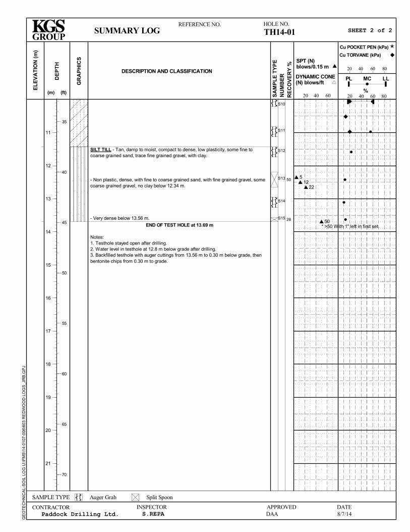
SILT TILL - Tan, damp to moist, compact to dense, low plasticity, some fine tocoarse grained sand, trace fine grained gravel, with clay.
- Non plastic, dense, with fine to coarse grained sand, with fine grained gravel, somecoarse grained gravel, no clay below 12.34 m.
- Very dense below 13.56 m.
END OF TEST HOLE at 13.69 m
Notes:1. Testhole stayed open after drilling.2. Water level in testhole at 12.8 m below grade after drilling.3. Backfilled testhole with auger cuttings from 13.56 m to 0.30 m below grade, thenbentonite chips from 0.30 m to grade.
50
28
S10
S11
S12
S13
S14
S15
DESCRIPTION AND CLASSIFICATION
(ft)
80
EL
EV
AT
ION
(m
)
60 80SA
MP
LE
TY
PE
PL LL
40
20
60
(m)
DE
PT
H
DYNAMIC CONE(N) blows/ft
60
SPT (N)blows/0.15 m
20 40%
RE
CO
VE
RY
%N
UM
BE
R
GR
AP
HIC
S
40
20
MC
Cu TORVANE (kPa)
Cu POCKET PEN (kPa)
SUMMARY LOG TH14-01HOLE NO.
APPROVED
SAMPLE TYPE
SHEET 2 of 2
CONTRACTOR INSPECTORS.REPA
Auger Grab
DATE
REFERENCE NO.
DAA
35
40
45
50
55
60
65
70
Split Spoon
11
12
13
14
15
16
17
18
19
20
21
Paddock Drilling Ltd.
GROUP
8/7/14
GE
OT
EC
HN
ICA
L-S
OIL
LO
G U
:\FM
S\1
4-01
07-0
06\6
03
RE
DW
OO
D L
OG
S_J
RB
.GP
J
512
22
50* >50 With 1" left in first set.

TOPSOIL - Black, damp to moist, trace rootlets.
CLAY FILL - Greyish black, moist, stiff, high plasticity, trace rootlets, trace coarsegrained sand.
SILT - Tan, moist, loose, low plasticity.
SILTY CLAY - Brown mottled with grey, moist, stiff, high plasticity.
- Silt lens (10-20 mm) at 1.98 m.- Trace silt nodules (1-2 mm) below 1.98 m.
- Trace oxidation below 2.44 m.- Firm below 2.59 m.
- Grey, no oxidation below 6.71 m.
- Soft below 7.47 m.
- Trace coarse grained gravel at 7.92 m.
- Trace coarse grained gravel at 8.53 m.
S1
S2
S3
S4
S5
S6
S7
S8
S9
DESCRIPTION AND CLASSIFICATION
(ft)
80
EL
EV
AT
ION
(m
)
60 80SA
MP
LE
TY
PE
PL LL
40
20
60
(m)
DE
PT
H
DYNAMIC CONE(N) blows/ft
60
SPT (N)blows/0.15 m
20 40%
RE
CO
VE
RY
%N
UM
BE
R
GR
AP
HIC
S
40
20
MC
Cu TORVANE (kPa)
Cu POCKET PEN (kPa)
DATE DRILLED
14-0107-006JOB NO.
5,531,643DRILLINGMETHOD
603 Redwood Ave - Firehall #6
125 mm ø Solid Stem Auger, ACKER SS Drill Rig
CITY OF WINNIPEG
PROJECT
WATER ELEV.
N
SITE
E
7 m West of South West Corner of Fire Hall TowerLOCATION
TOP OF PVC ELEV.Addition to Fire Station #6 at 603 Redwood Ave - GeotechnicalInvestigation
CLIENT
UTM (m)
633,112
GROUND ELEV.
07/05/2014
SUMMARY LOG TH14-02HOLE NO.
APPROVED
SAMPLE TYPE
SHEET 1 of 2
CONTRACTOR INSPECTORS.REPA
Auger Grab
DATE
REFERENCE NO.
DAA
5
10
15
20
25
30
Split Spoon
1
2
3
4
5
6
7
8
9
Paddock Drilling Ltd.
GROUP
8/7/14
GE
OT
EC
HN
ICA
L-S
OIL
LO
G U
:\FM
S\1
4-01
07-0
06\6
03
RE
DW
OO
D L
OG
S_J
RB
.GP
J
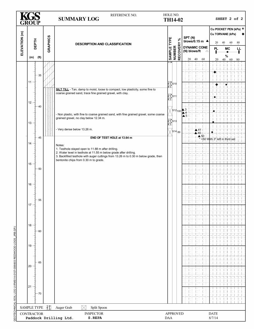
SILT TILL - Tan, damp to moist, loose to compact, low plasticity, some fine tocoarse grained sand, trace fine grained gravel, with clay.
- Non plastic, with fine to coarse grained sand, with fine grained gravel, some coarsegrained gravel, no clay below 12.34 m.
- Very dense below 13.26 m.
END OF TEST HOLE at 13.64 m
Notes:1. Testhole stayed open to 11.88 m after drilling.2. Water level in testhole at 11.55 m below grade after drilling.3. Backfilled testhole with auger cuttings from 13.26 m to 0.30 m below grade, thenbentonite chips from 0.30 m to grade.
100
89
S10
S11
S12
S13
S14
DESCRIPTION AND CLASSIFICATION
(ft)
80
EL
EV
AT
ION
(m
)
60 80SA
MP
LE
TY
PE
PL LL
40
20
60
(m)
DE
PT
H
DYNAMIC CONE(N) blows/ft
60
SPT (N)blows/0.15 m
20 40%
RE
CO
VE
RY
%N
UM
BE
R
GR
AP
HIC
S
40
20
MC
Cu TORVANE (kPa)
Cu POCKET PEN (kPa)
SUMMARY LOG TH14-02HOLE NO.
APPROVED
SAMPLE TYPE
SHEET 2 of 2
CONTRACTOR INSPECTORS.REPA
Auger Grab
DATE
REFERENCE NO.
DAA
35
40
45
50
55
60
65
70
Split Spoon
11
12
13
14
15
16
17
18
19
20
21
Paddock Drilling Ltd.
GROUP
8/7/14
GE
OT
EC
HN
ICA
L-S
OIL
LO
G U
:\FM
S\1
4-01
07-0
06\6
03
RE
DW
OO
D L
OG
S_J
RB
.GP
J
345
4140
50* >50 With 3" left in third set