drawings - winnipegwinnipeg.ca/finance/findata/matmgt/documents/2012/217-2012/217... ·...
TRANSCRIPT

Fort Rouge Leisure Centre Section 01 33 00 HVAC Upgrades – Phase 2 Page 1 of 2 Bid Opportunity No. 217-2012 March 2012
SUBMITTAL PROCEDURES
P:\Projects\2011\11-0107-02\Doc.Control\Issued\SOURCE\Docs\HVAC Upgrade Phase 2 FINAL SPEC\01-FrontEnd\BO-217-2012 FRLC-HVAC Upgrades-Phase 2-Dwg&SpecList.doc
DRAWINGS Drawing No. Drawing Name/Title Cover Sheet Structural P2-S01 Roof/Ceiling Space Plan P2-S02 Main Floor Plan P2-S03 Partial Plans, Section and Details Mechanical P2-M01 Main Floor Plan Existing Ductwork P2-M02 Mezzanine/Second Floor Plan – Existing Ductwork P2-M03 Main Floor Plan – New Piping P2-M04 Second/Mezzanine Floor Plan – New Piping P2-M05 Main Floor Plan – New HVAC P2-M06 Second/Mezzanine Floor Plan – New HVAC P2-M07 Boiler Room Plan P2-M08 Sections and Details P2-M09 Hydronic Heating Piping Schematic P2-M10 Controls Schematic P2-M11 Boiler Room Plan – Sprinkler System Upgrades Electrical P1-E01 Main Floor Power Arrangement P1-E02 Second/Mezzanine Floor Plan – Power Arrangement P1-E03 Main Floor Plan – Fire Alarm Arrangement P1-E04 Second/Mezzanine Floor Plan – Fire Alarm Arrangement P1-E05 Electrical Schedules
DIVISION 01 – GENERAL REQUIREMENTS Specification No. Specification Title 01 33 00 Submittal Procedures 01 78 00 Closeout Submittals 01 79 00 Demonstration and Training 01 91 13 General Commissioning (Cx) Requirements 01 91 33 Commissioning Forms
DIVISION 22 – PLUMBING Specification No. Specification Title 22 05 00 Common Work Results for Plumbing 22 13 18 Drainage Waste and Vent Piping - Plastic

Fort Rouge Leisure Centre Section 01 33 00 HVAC Upgrades – Phase 2 Page 2 of 2 Bid Opportunity No. 217-2012 March 2012
SUBMITTAL PROCEDURES
P:\Projects\2011\11-0107-02\Doc.Control\Issued\SOURCE\Docs\HVAC Upgrade Phase 2 FINAL SPEC\01-FrontEnd\BO-217-2012 FRLC-HVAC Upgrades-Phase 2-Dwg&SpecList.doc
DIVISION 23 – HEATING, VENTILATING, AND AIR CONDITIONING Specification No. Specification Title
23 05 00 Common Work Results for HVAC 23 05 01 Use of HVAC Systems During Construction 23 05 13 Common Motor Requirements for HVAC Equipment 23 05 21 Thermometers and Pressure Gauges – Piping Systems 23 05 29 Hangers and Supports for HVAC Piping and Equipment 23 05 54 Mechanical Identification 23 05 93 Testing Adjusting and Balancing for HVAC 23 07 12 Thermal Insulation For Piping 23 07 13 Thermal Insulation For Ducting 23 09 33 Control System for HVAC 23 21 16 Hydronic Systems: Steel 23 21 23 Hydronic Pumps 23 23 00 Refrigerant Piping 23 31 14 Metal Ducts – Low Pressure to 500 PA 23 33 00 Air Duct Accessories 23 33 14 Dampers - Balancing 23 37 20 Louvres, Intakes and Vents 23 52 00 Boilers 23 73 11 Air Handling Units 23 73 12 Reheat Coils 23 82 39 Unit Heaters
DIVISION 26 – ELECTRICAL Specification No. Specification Title 26 05 01 Common Work Results - Electrical 26 05 02 Mechanical Equipment Connections 26 05 20 Wire Box Connectors – 0 - 1000 V 26 05 21 Wire and Cables (0 - 1000 V) 26 05 31 Splitters, Junction, Pull Boxes and Cabinets 26 05 32 Outlet Boxes, Conduit Boxes and Fittings 26 05 34 Conduits, Conduit Fastenings and Conduit Fittings 26 05 80 Fractional Horsepower Motors 26 05 81 Motors: 1 to 200 HPKW to 149KW, to 600 V 26 24 17 Panelboards Breaker Type 26 27 16 Electrical Cabinets and Enclosures 26 27 26 Wiring Devices 26 28 23 Disconnect Switches – Fused and Non-Fused 26 29 01 Contactors 26 29 03 Control Devices 26 29 10 Motor Starters to 600 V 26 29 23 Variable Speed Drives 28 31 01 Fire Alarm Systems
Fort Rouge Leisure Centre Section 01 33 00 HVAC Upgrades – Phase 2 Page 1 of 3 Bid Opportunity No. 217-2012 March 2012
SUBMITTAL PROCEDURES
P:\Projects\2011\11-0107-02\Doc.Control\Issued\SOURCE\Docs\HVAC Upgrade Phase 2 FINAL SPEC\02-General Requirements\013300.doc
Part 1 General
1.1 ADMINISTRATIVE
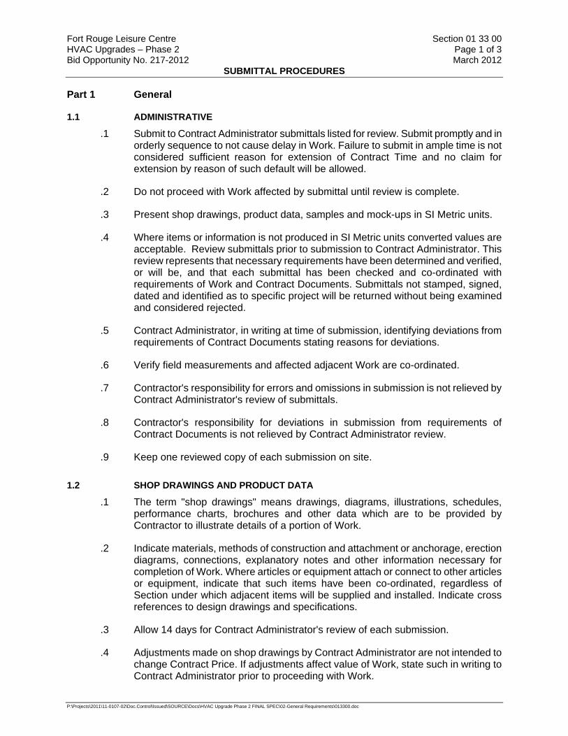
.1 Submit to Contract Administrator submittals listed for review. Submit promptly and in orderly sequence to not cause delay in Work. Failure to submit in ample time is not considered sufficient reason for extension of Contract Time and no claim for extension by reason of such default will be allowed.
.2 Do not proceed with Work affected by submittal until review is complete.
.3 Present shop drawings, product data, samples and mock-ups in SI Metric units.
.4 Where items or information is not produced in SI Metric units converted values are acceptable. Review submittals prior to submission to Contract Administrator. This review represents that necessary requirements have been determined and verified, or will be, and that each submittal has been checked and co-ordinated with requirements of Work and Contract Documents. Submittals not stamped, signed, dated and identified as to specific project will be returned without being examined and considered rejected.
.5 Contract Administrator, in writing at time of submission, identifying deviations from requirements of Contract Documents stating reasons for deviations.
.6 Verify field measurements and affected adjacent Work are co-ordinated.
.7 Contractor's responsibility for errors and omissions in submission is not relieved by Contract Administrator's review of submittals.
.8 Contractor's responsibility for deviations in submission from requirements of Contract Documents is not relieved by Contract Administrator review.
.9 Keep one reviewed copy of each submission on site.
1.2 SHOP DRAWINGS AND PRODUCT DATA
.1 The term "shop drawings" means drawings, diagrams, illustrations, schedules, performance charts, brochures and other data which are to be provided by Contractor to illustrate details of a portion of Work.
.2 Indicate materials, methods of construction and attachment or anchorage, erection diagrams, connections, explanatory notes and other information necessary for completion of Work. Where articles or equipment attach or connect to other articles or equipment, indicate that such items have been co-ordinated, regardless of Section under which adjacent items will be supplied and installed. Indicate cross references to design drawings and specifications.
.3 Allow 14 days for Contract Administrator's review of each submission.
.4 Adjustments made on shop drawings by Contract Administrator are not intended to change Contract Price. If adjustments affect value of Work, state such in writing to Contract Administrator prior to proceeding with Work.

Fort Rouge Leisure Centre Section 01 33 00 HVAC Upgrades – Phase 2 Page 2 of 3 Bid Opportunity No. 217-2012 March 2012
SUBMITTAL PROCEDURES
P:\Projects\2011\11-0107-02\Doc.Control\Issued\SOURCE\Docs\HVAC Upgrade Phase 2 FINAL SPEC\02-General Requirements\013300.doc
.5 Make changes in shop drawings as Contract Administrator may require, consistent with Contract Documents. When resubmitting, notify Contract Administrator in writing of revisions other than those requested.
.6 Accompany submissions with transmittal letter, containing:
.1 Date.
.2 Project title and number.
.3 Contractor's name and address.
.4 Identification and quantity of each shop drawing, product data and sample.
.5 Other pertinent data.
.7 Submissions include:
.1 Date and revision dates.
.2 Project title and number.
.3 Name and address of: Subcontractor. Supplier. Manufacturer.
.4 Contractor's stamp, signed by Contractor's authorized representative certifying approval of submissions, verification of field measurements and compliance with Contract Documents.
.5 Details of appropriate portions of Work as applicable: Fabrication. Layout, showing dimensions, including identified field dimensions, and clearances. Setting or erection details. Capacities. Performance characteristics. Standards. Operating weight. Wiring diagrams. Single line and schematic diagrams. Relationship to adjacent work.
.8 After Contract Administrator's review, distribute copies.
.9 Submit electronic (PDF format) copies of product data sheets or brochures for requirements requested in specification Sections and as requested by Contract Administrator where shop drawings will not be prepared due to standardized manufacture of product.
.10 Submit electronic (PDF format) copies of test reports for requirements requested in specification Sections and as requested by Contract Administrator.
.1 Report signed by authorized official of testing laboratory that material, product or system identical to material, product or system to be provided has been tested in accord with specified requirements.
.11 Submit electronic (PDF format) copies of certificates for requirements requested in specification Sections and as requested by Contract Administrator.
Fort Rouge Leisure Centre Section 01 33 00 HVAC Upgrades – Phase 2 Page 3 of 3 Bid Opportunity No. 217-2012 March 2012
SUBMITTAL PROCEDURES
P:\Projects\2011\11-0107-02\Doc.Control\Issued\SOURCE\Docs\HVAC Upgrade Phase 2 FINAL SPEC\02-General Requirements\013300.doc
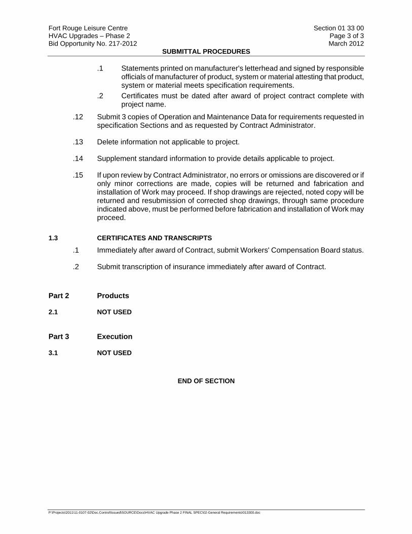
.1 Statements printed on manufacturer's letterhead and signed by responsible officials of manufacturer of product, system or material attesting that product, system or material meets specification requirements.
.2 Certificates must be dated after award of project contract complete with project name.
.12 Submit 3 copies of Operation and Maintenance Data for requirements requested in specification Sections and as requested by Contract Administrator.
.13 Delete information not applicable to project.
.14 Supplement standard information to provide details applicable to project.
.15 If upon review by Contract Administrator, no errors or omissions are discovered or if only minor corrections are made, copies will be returned and fabrication and installation of Work may proceed. If shop drawings are rejected, noted copy will be returned and resubmission of corrected shop drawings, through same procedure indicated above, must be performed before fabrication and installation of Work may proceed.
1.3 CERTIFICATES AND TRANSCRIPTS
.1 Immediately after award of Contract, submit Workers' Compensation Board status.
.2 Submit transcription of insurance immediately after award of Contract.
Part 2 Products
2.1 NOT USED
Part 3 Execution
3.1 NOT USED
END OF SECTION
Fort Rouge Leisure Centre Section 01 78 00 HVAC Upgrades – Phase 2 Page 1 of 7 Bid Opportunity No. 217-2012 March 2012
CLOSEOUT SUBMITTALS
P:\Projects\2011\11-0107-02\Doc.Control\Issued\SOURCE\Docs\HVAC Upgrade Phase 2 FINAL SPEC\02-General Requirements\017800.doc
Part 1 General
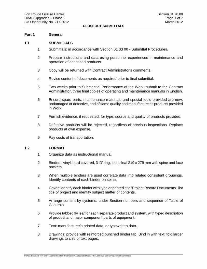
1.1 SUBMITTALS .1 Submittals: in accordance with Section 01 33 00 - Submittal Procedures.
.2 Prepare instructions and data using personnel experienced in maintenance and operation of described products.
.3 Copy will be returned with Contract Administrator's comments.
.4 Revise content of documents as required prior to final submittal.
.5 Two weeks prior to Substantial Performance of the Work, submit to the Contract Administrator, three final copies of operating and maintenance manuals in English.
.6 Ensure spare parts, maintenance materials and special tools provided are new, undamaged or defective, and of same quality and manufacture as products provided in Work.
.7 Furnish evidence, if requested, for type, source and quality of products provided.
.8 Defective products will be rejected, regardless of previous inspections. Replace products at own expense.
.9 Pay costs of transportation.
1.2 FORMAT .1 Organize data as instructional manual.
.2 Binders: vinyl, hard covered, 3 'D' ring, loose leaf 219 x 279 mm with spine and face pockets.
.3 When multiple binders are used correlate data into related consistent groupings. Identify contents of each binder on spine.
.4 Cover: identify each binder with type or printed title 'Project Record Documents'; list title of project and identify subject matter of contents.
.5 Arrange content by systems, under Section numbers and sequence of Table of Contents.
.6 Provide tabbed fly leaf for each separate product and system, with typed description of product and major component parts of equipment.
.7 Text: manufacturer's printed data, or typewritten data.
.8 Drawings: provide with reinforced punched binder tab. Bind in with text; fold larger drawings to size of text pages.

Fort Rouge Leisure Centre Section 01 78 00 HVAC Upgrades – Phase 2 Page 2 of 7 Bid Opportunity No. 217-2012 March 2012
CLOSEOUT SUBMITTALS
P:\Projects\2011\11-0107-02\Doc.Control\Issued\SOURCE\Docs\HVAC Upgrade Phase 2 FINAL SPEC\02-General Requirements\017800.doc
1.3 CONTENTS - EACH VOLUME .1 Table of Contents: provide title of project; Date of submission; names.
.1 Addresses, and telephone numbers of Contract Administrator and Contractor with name of responsible parties.
.2 Schedule of products and systems, indexed to content of volume.
.2 For each product or system:
.1 List names, addresses and telephone numbers of subcontractors and suppliers, including local source of supplies and replacement parts.
.3 Product Data: mark each sheet to identify specific products and component parts, and data applicable to installation; delete inapplicable information.
.4 Drawings: supplement product data to illustrate relations of component parts of equipment and systems, to show control and flow diagrams.
.5 Typewritten Text: as required to supplement product data. Provide logical sequence of instructions for each procedure.
.6 Training: refer to Section 01 79 00 - Demonstration and Training.
1.4 AS-BUILTS AND SAMPLES .1 Maintain, in addition to requirements in General Conditions, at site for Contract
Administrator one record copy of:
.1 Contract Drawings.
.2 Specifications.
.3 Addenda.
.4 Change Orders and other modifications to Contract.
.5 Reviewed shop drawings, product data, and samples.Field test records.
.6 Inspection certificates.
.7 Manufacturer's certificates.
.2 Store record documents and samples in field office apart from documents used for construction. Provide files, racks, and secure storage.
.3 Label record documents and file in accordance with Section number listings in List of Contents of this Project Manual. Label each document "PROJECT RECORD" in neat, large, printed letters.
.4 Maintain record documents in clean, dry and legible condition. Do not use record documents for construction purposes.
.5 Keep record documents and samples available for inspection by Contract Administrator.
Fort Rouge Leisure Centre Section 01 78 00 HVAC Upgrades – Phase 2 Page 3 of 7 Bid Opportunity No. 217-2012 March 2012
CLOSEOUT SUBMITTALS
P:\Projects\2011\11-0107-02\Doc.Control\Issued\SOURCE\Docs\HVAC Upgrade Phase 2 FINAL SPEC\02-General Requirements\017800.doc
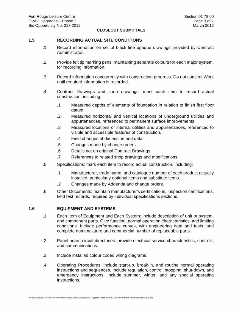
1.5 RECORDING ACTUAL SITE CONDITIONS .1 Record information on set of black line opaque drawings provided by Contract
Administrator.
.2 Provide felt tip marking pens, maintaining separate colours for each major system, for recording information.
.3 Record information concurrently with construction progress. Do not conceal Work until required information is recorded.
.4 Contract Drawings and shop drawings: mark each item to record actual construction, including:
.1 Measured depths of elements of foundation in relation to finish first floor datum.
.2 Measured horizontal and vertical locations of underground utilities and appurtenances, referenced to permanent surface improvements.
.3 Measured locations of internal utilities and appurtenances, referenced to visible and accessible features of construction.
.4 Field changes of dimension and detail.
.5 Changes made by change orders.
.6 Details not on original Contract Drawings.
.7 References to related shop drawings and modifications.
.5 Specifications: mark each item to record actual construction, including:
.1 Manufacturer, trade name, and catalogue number of each product actually installed, particularly optional items and substitute items.
.2 Changes made by Addenda and change orders.
.6 Other Documents: maintain manufacturer's certifications, inspection certifications, field test records, required by individual specifications sections.
1.6 EQUIPMENT AND SYSTEMS .1 Each Item of Equipment and Each System: include description of unit or system,
and component parts. Give function, normal operation characteristics, and limiting conditions. Include performance curves, with engineering data and tests, and complete nomenclature and commercial number of replaceable parts.
.2 Panel board circuit directories: provide electrical service characteristics, controls, and communications.
.3 Include installed colour coded wiring diagrams.
.4 Operating Procedures: include start-up, break-in, and routine normal operating instructions and sequences. Include regulation, control, stopping, shut-down, and emergency instructions. Include summer, winter, and any special operating instructions.
Fort Rouge Leisure Centre Section 01 78 00 HVAC Upgrades – Phase 2 Page 4 of 7 Bid Opportunity No. 217-2012 March 2012
CLOSEOUT SUBMITTALS
P:\Projects\2011\11-0107-02\Doc.Control\Issued\SOURCE\Docs\HVAC Upgrade Phase 2 FINAL SPEC\02-General Requirements\017800.doc
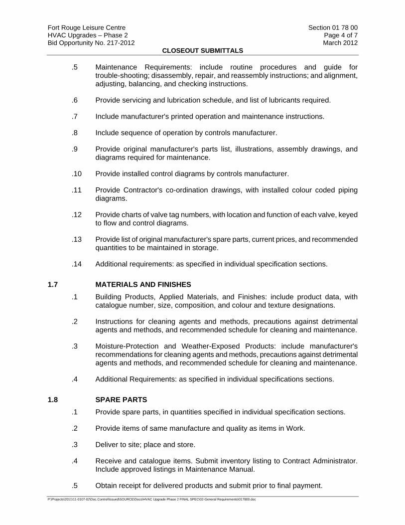
.5 Maintenance Requirements: include routine procedures and guide for trouble-shooting; disassembly, repair, and reassembly instructions; and alignment, adjusting, balancing, and checking instructions.
.6 Provide servicing and lubrication schedule, and list of lubricants required.
.7 Include manufacturer's printed operation and maintenance instructions.
.8 Include sequence of operation by controls manufacturer.
.9 Provide original manufacturer's parts list, illustrations, assembly drawings, and diagrams required for maintenance.
.10 Provide installed control diagrams by controls manufacturer.
.11 Provide Contractor's co-ordination drawings, with installed colour coded piping diagrams.
.12 Provide charts of valve tag numbers, with location and function of each valve, keyed to flow and control diagrams.
.13 Provide list of original manufacturer's spare parts, current prices, and recommended quantities to be maintained in storage.
.14 Additional requirements: as specified in individual specification sections.
1.7 MATERIALS AND FINISHES .1 Building Products, Applied Materials, and Finishes: include product data, with
catalogue number, size, composition, and colour and texture designations.
.2 Instructions for cleaning agents and methods, precautions against detrimental agents and methods, and recommended schedule for cleaning and maintenance.
.3 Moisture-Protection and Weather-Exposed Products: include manufacturer's recommendations for cleaning agents and methods, precautions against detrimental agents and methods, and recommended schedule for cleaning and maintenance.
.4 Additional Requirements: as specified in individual specifications sections.
1.8 SPARE PARTS .1 Provide spare parts, in quantities specified in individual specification sections.
.2 Provide items of same manufacture and quality as items in Work.
.3 Deliver to site; place and store.
.4 Receive and catalogue items. Submit inventory listing to Contract Administrator. Include approved listings in Maintenance Manual.
.5 Obtain receipt for delivered products and submit prior to final payment.

Fort Rouge Leisure Centre Section 01 78 00 HVAC Upgrades – Phase 2 Page 5 of 7 Bid Opportunity No. 217-2012 March 2012
CLOSEOUT SUBMITTALS
P:\Projects\2011\11-0107-02\Doc.Control\Issued\SOURCE\Docs\HVAC Upgrade Phase 2 FINAL SPEC\02-General Requirements\017800.doc
1.9 MAINTENANCE MATERIALS .1 Provide maintenance and extra materials, in quantities specified in individual
specification sections.
.2 Provide items of same manufacture and quality as items in Work.
.3 Deliver to site; place and store.
.4 Receive and catalogue items. Submit inventory listing to Contract Administrator. Include approved listings in Maintenance Manual.
.5 Obtain receipt for delivered products and submit prior to final payment.
1.10 SPECIAL TOOLS .1 Provide special tools, in quantities specified in individual specification section.
.2 Provide items with tags identifying their associated function and equipment.
.3 Deliver to site; place and store. Receive and catalogue items. Submit inventory listing to Contract Administrator. Include approved listings in Maintenance Manual.
1.11 STORAGE, HANDLING AND PROTECTION .1 Store spare parts, maintenance materials, and special tools in manner to prevent
damage or deterioration.
.2 Store in original and undamaged condition with manufacturer's seal and labels intact.
.3 Store components subject to damage from weather in weatherproof enclosures.
.4 Store paints and freezable materials in a heated and ventilated room.
.5 Remove and replace damaged products at own expense and to satisfaction of Contract Administrator.
1.12 WARRANTIES AND BONDS .1 Develop warranty management plan to contain information relevant to Warranties.
.2 Submit warranty management plan, 30 days before planned pre-warranty conference, to Contract Administrator approval.
.3 Warranty management plan to include required actions and documents to assure that Contract Administrator receives warranties to which it is entitled.
.4 Provide plan in narrative form and contain sufficient detail to make it suitable for use by future maintenance and repair personnel.
.5 Submit, warranty information made available during construction phase, to Contract Administrator for approval prior to each monthly pay estimate.
Fort Rouge Leisure Centre Section 01 78 00 HVAC Upgrades – Phase 2 Page 6 of 7 Bid Opportunity No. 217-2012 March 2012
CLOSEOUT SUBMITTALS
P:\Projects\2011\11-0107-02\Doc.Control\Issued\SOURCE\Docs\HVAC Upgrade Phase 2 FINAL SPEC\02-General Requirements\017800.doc
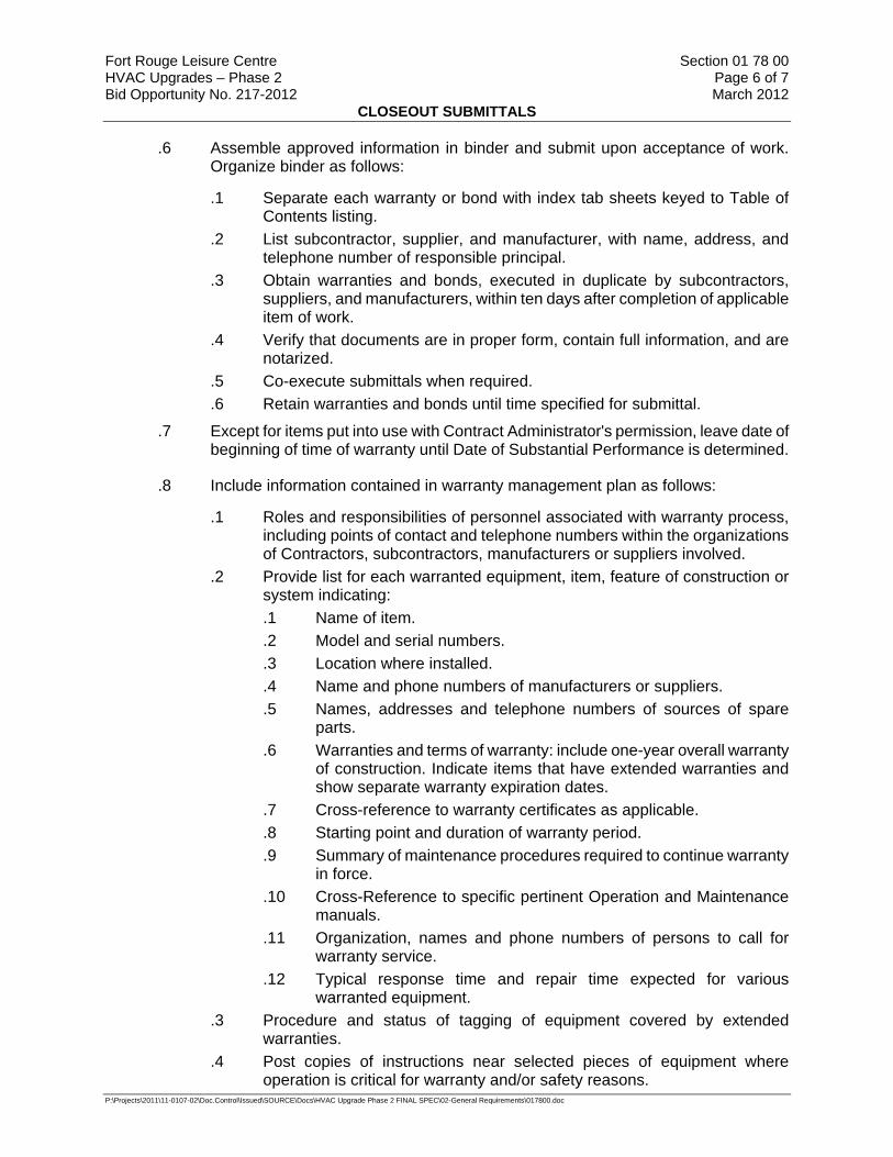
.6 Assemble approved information in binder and submit upon acceptance of work. Organize binder as follows:
.1 Separate each warranty or bond with index tab sheets keyed to Table of Contents listing.
.2 List subcontractor, supplier, and manufacturer, with name, address, and telephone number of responsible principal.
.3 Obtain warranties and bonds, executed in duplicate by subcontractors, suppliers, and manufacturers, within ten days after completion of applicable item of work.
.4 Verify that documents are in proper form, contain full information, and are notarized.
.5 Co-execute submittals when required.
.6 Retain warranties and bonds until time specified for submittal.
.7 Except for items put into use with Contract Administrator's permission, leave date of beginning of time of warranty until Date of Substantial Performance is determined.
.8 Include information contained in warranty management plan as follows:
.1 Roles and responsibilities of personnel associated with warranty process, including points of contact and telephone numbers within the organizations of Contractors, subcontractors, manufacturers or suppliers involved.
.2 Provide list for each warranted equipment, item, feature of construction or system indicating: .1 Name of item. .2 Model and serial numbers. .3 Location where installed. .4 Name and phone numbers of manufacturers or suppliers. .5 Names, addresses and telephone numbers of sources of spare
parts. .6 Warranties and terms of warranty: include one-year overall warranty
of construction. Indicate items that have extended warranties and show separate warranty expiration dates.
.7 Cross-reference to warranty certificates as applicable.
.8 Starting point and duration of warranty period.
.9 Summary of maintenance procedures required to continue warranty in force.
.10 Cross-Reference to specific pertinent Operation and Maintenance manuals.
.11 Organization, names and phone numbers of persons to call for warranty service.
.12 Typical response time and repair time expected for various warranted equipment.
.3 Procedure and status of tagging of equipment covered by extended warranties.
.4 Post copies of instructions near selected pieces of equipment where operation is critical for warranty and/or safety reasons.

Fort Rouge Leisure Centre Section 01 78 00 HVAC Upgrades – Phase 2 Page 7 of 7 Bid Opportunity No. 217-2012 March 2012
CLOSEOUT SUBMITTALS
P:\Projects\2011\11-0107-02\Doc.Control\Issued\SOURCE\Docs\HVAC Upgrade Phase 2 FINAL SPEC\02-General Requirements\017800.doc
.9 Respond in a timely manner to oral or written notification of required construction warranty repair work.
.10 Written verification will follow oral instructions. Failure to respond will be cause for the Contract Administrator to proceed with action against Contractor.
1.13 WARRANTY TAGS .1 Tag, at time of installation, each warranted item. Provide durable, oil and water
resistant tag approved by Contract Administrator.
.2 Attach tags with copper wire and spray with waterproof silicone coating.
.3 Leave date of acceptance until project is accepted for occupancy.
.4 Indicate following information on tag:
.1 Type of product/material.
.2 Model number.
.3 Serial number.
.4 Contract number.Warranty period.
.5 Inspector's signature.
.6 Construction Contractor.
Part 2 Products
2.1 NOT USED .1 Not Used.
Part 3 Execution
3.1 NOT USED .1 Not Used.
END OF SECTION

Fort Rouge Leisure Centre Section 01 79 00 HVAC Upgrades – Phase 2 Page 1 of 2 Bid Opportunity No. 217-2012 March 2012
DEMONSTRATION AND TRAINING
P:\Projects\2011\11-0107-02\Doc.Control\Issued\SOURCE\Docs\HVAC Upgrade Phase 2 FINAL SPEC\02-General Requirements\017900.doc
Part 1 General
1.1 DESCRIPTION .1 Demonstrate scheduled operation and maintenance of equipment and systems to
Contract Administrator's personnel two weeks prior to date of final inspection.
.2 Contract Administrator will provide list of personnel to receive instructions, and will co-ordinate their attendance at agreed-upon times.
1.2 QUALITY CONTROL .1 When specified in individual Sections require manufacturer to provide authorized
representative to demonstrate operation of equipment and systems, instruct Contract Administrator's personnel, and provide written report that demonstration and instructions have been completed.
1.3 SUBMITTALS .1 Submittals: in accordance with Section 01 33 00 - Submittal Procedures.
.2 Submit schedule of time and date for demonstration of each item of equipment and each system two weeks prior to designated dates, for Contract Administrator's approval. Submit reports within one week after completion of demonstration, that demonstration and instructions have been satisfactorily completed.
.3 Give time and date of each demonstration, with list of persons present.
1.4 CONDITIONS FOR DEMONSTRATIONS .1 Equipment has been inspected and put into operation.
.2 Provide copies of completed operation and maintenance manuals for use in demonstrations and instructions.
1.5 PREPARATION .1 Verify that conditions for demonstration and instructions comply with requirements.
.2 Verify that designated personnel are present.
1.6 DEMONSTRATION AND INSTRUCTIONS .1 Demonstrate start-up, operation, control, adjustment, trouble-shooting, servicing,
and maintenance of each item of equipment at scheduled times, at the equipment location.
.2 Instruct personnel in phases of operation and maintenance using operation and maintenance manuals as basis of instruction.
.3 Review contents of manual in detail to explain aspects of operation and maintenance.
Fort Rouge Leisure Centre Section 01 79 00 HVAC Upgrades – Phase 2 Page 2 of 2 Bid Opportunity No. 217-2012 March 2012
DEMONSTRATION AND TRAINING
P:\Projects\2011\11-0107-02\Doc.Control\Issued\SOURCE\Docs\HVAC Upgrade Phase 2 FINAL SPEC\02-General Requirements\017900.doc
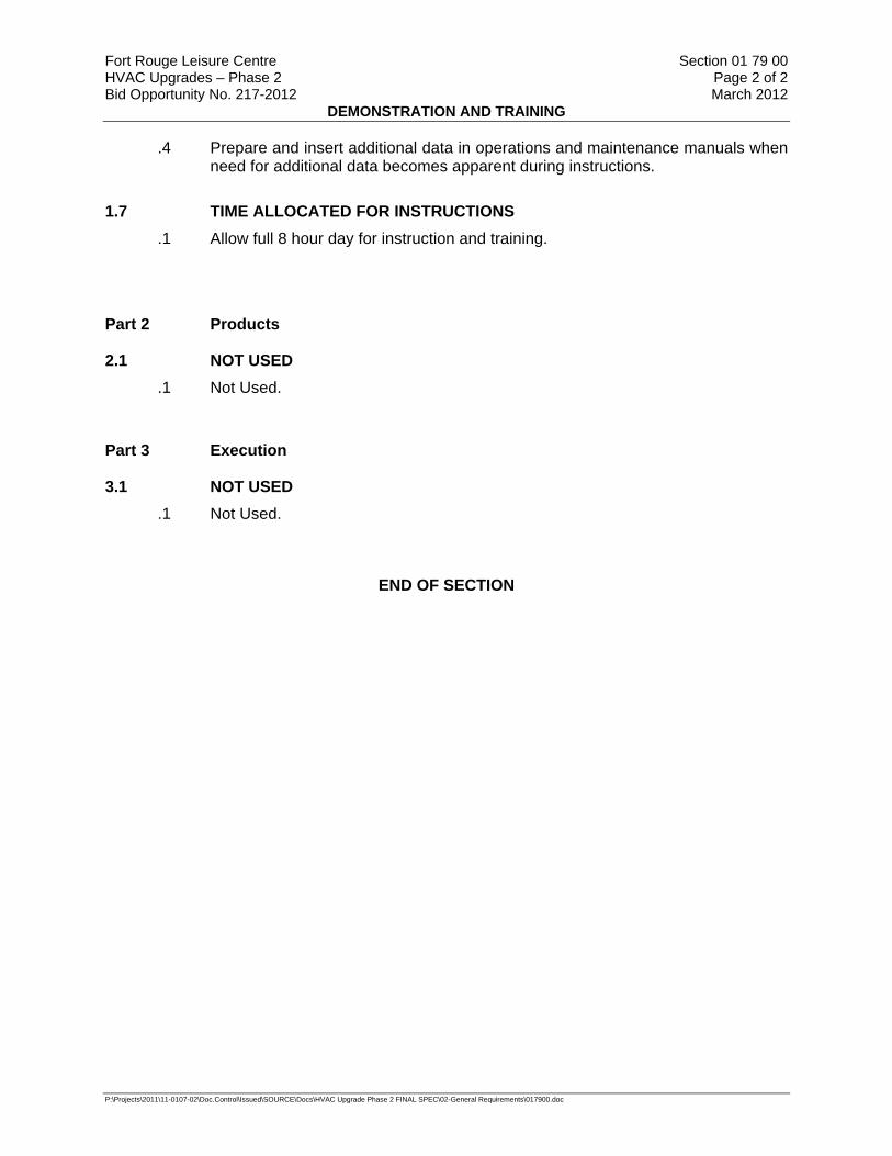
.4 Prepare and insert additional data in operations and maintenance manuals when need for additional data becomes apparent during instructions.
1.7 TIME ALLOCATED FOR INSTRUCTIONS .1 Allow full 8 hour day for instruction and training.
Part 2 Products
2.1 NOT USED .1 Not Used.
Part 3 Execution
3.1 NOT USED .1 Not Used.
END OF SECTION
Fort Rouge Leisure Centre Section 01 91 13 HVAC Upgrades – Phase 2 Page 1 of 7 Bid Opportunity No. 217-2012 March 2012
GENERAL COMMISSIONING (CX) REQUIREMENTS
P:\Projects\2011\11-0107-02\Doc.Control\Issued\SOURCE\Docs\HVAC Upgrade Phase 2 FINAL SPEC\02-General Requirements\019113.doc
Part 1 General
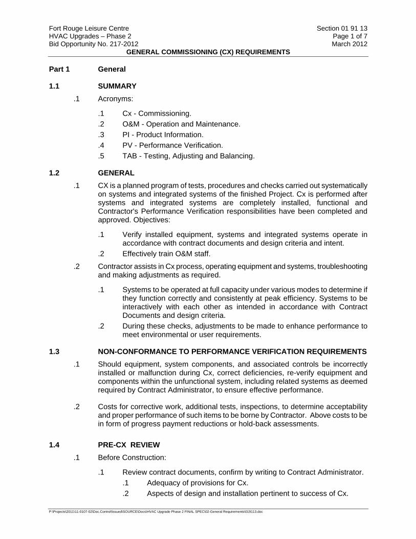
1.1 SUMMARY .1 Acronyms:
.1 Cx - Commissioning.
.2 O&M - Operation and Maintenance.
.3 PI - Product Information.
.4 PV - Performance Verification.
.5 TAB - Testing, Adjusting and Balancing.
1.2 GENERAL .1 CX is a planned program of tests, procedures and checks carried out systematically
on systems and integrated systems of the finished Project. Cx is performed after systems and integrated systems are completely installed, functional and Contractor's Performance Verification responsibilities have been completed and approved. Objectives:
.1 Verify installed equipment, systems and integrated systems operate in accordance with contract documents and design criteria and intent.
.2 Effectively train O&M staff.
.2 Contractor assists in Cx process, operating equipment and systems, troubleshooting and making adjustments as required.
.1 Systems to be operated at full capacity under various modes to determine if they function correctly and consistently at peak efficiency. Systems to be interactively with each other as intended in accordance with Contract Documents and design criteria.
.2 During these checks, adjustments to be made to enhance performance to meet environmental or user requirements.
1.3 NON-CONFORMANCE TO PERFORMANCE VERIFICATION REQUIREMENTS .1 Should equipment, system components, and associated controls be incorrectly
installed or malfunction during Cx, correct deficiencies, re-verify equipment and components within the unfunctional system, including related systems as deemed required by Contract Administrator, to ensure effective performance.
.2 Costs for corrective work, additional tests, inspections, to determine acceptability and proper performance of such items to be borne by Contractor. Above costs to be in form of progress payment reductions or hold-back assessments.
1.4 PRE-CX REVIEW .1 Before Construction:
.1 Review contract documents, confirm by writing to Contract Administrator. .1 Adequacy of provisions for Cx. .2 Aspects of design and installation pertinent to success of Cx.

Fort Rouge Leisure Centre Section 01 91 13 HVAC Upgrades – Phase 2 Page 2 of 7 Bid Opportunity No. 217-2012 March 2012
GENERAL COMMISSIONING (CX) REQUIREMENTS
P:\Projects\2011\11-0107-02\Doc.Control\Issued\SOURCE\Docs\HVAC Upgrade Phase 2 FINAL SPEC\02-General Requirements\019113.doc
.2 During Construction:
.1 Co-ordinate provision, location and installation of provisions for Cx.
.3 Before start of Cx:
.1 Have completed Cx Plan up-to-date.
.2 Ensure installation of related components, equipment, sub-systems, systems is complete.
.3 Fully understand Cx requirements and procedures.
.4 Have Cx documentation shelf-ready.
.5 Understand completely design criteria and intent and special features.
.6 Submit complete start-up documentation to Contract Administrator.
.7 Have Cx schedules up-to-date.
.8 Ensure systems have been cleaned thoroughly.
.9 Complete TAB procedures on systems, submit TAB reports to Contract Administrator for review and approval.
.10 Ensure "As-Built" system schematics are available.
.4 Inform Contract Administrator in writing of discrepancies and deficiencies on finished works.
1.5 SUBMITTALS .1 Submittals: in accordance with Section 01 33 00 - Submittal Procedures.
1.6 COMMISSIONING DOCUMENTATION .1 Contract Administrator to review and approve Cx documentation.
.2 Provide completed and approved Cx documentation to Contract Administrator.
1.7 STARTING AND TESTING .1 Contractor assumes liabilities and costs for inspections. Including disassembly and
re-assembly after approval, starting, testing and adjusting, including supply of testing equipment.
1.8 WITNESSING OF STARTING AND TESTING .1 Provide 14 days notice prior to commencement.
.2 Contract Administrator representative to witness of start-up and testing.
1.9 MANUFACTURER'S INVOLVEMENT .1 Factory testing: manufacturer to:
.1 Coordinate time and location of testing.
.2 Provide testing documentation for approval by Contract Administrator.

Fort Rouge Leisure Centre Section 01 91 13 HVAC Upgrades – Phase 2 Page 3 of 7 Bid Opportunity No. 217-2012 March 2012
GENERAL COMMISSIONING (CX) REQUIREMENTS
P:\Projects\2011\11-0107-02\Doc.Control\Issued\SOURCE\Docs\HVAC Upgrade Phase 2 FINAL SPEC\02-General Requirements\019113.doc
.3 Obtain written approval of test results and documentation from Contract Administrator before delivery to site.
.2 Obtain manufacturers installation, start-up and operations instructions prior to start-up of components, equipment and systems and review with Contract Administrator.
.1 Compare completed installation with manufacturer's published data, record discrepancies, and review with manufacturer.
.2 Modify procedures detrimental to equipment performance and review same with manufacturer before start-up.
.3 Integrity of warranties:
.1 Use manufacturer's trained start-up personnel where specified elsewhere in other divisions or required to maintain integrity of warranty.
.2 Verify with manufacturer that testing as specified will not void warranties.
.4 Qualifications of manufacturer's personnel:
.1 Experienced in design, installation and operation of equipment and systems.
.2 Ability to interpret test results accurately.
.3 To report results in clear, concise, logical manner.
1.10 PROCEDURES .1 Verify that equipment and systems are complete, clean, and operating in normal and
safe manner prior to conducting start-up, testing and Cx.
.2 Conduct start-up and testing in following distinct phases:
.1 Included in delivery and installation: .1 Verification of conformity to specification, approved shop drawings
and completion of PI report forms. .2 Visual inspection of quality of installation.
.2 Start-up: follow accepted start-up procedures.
.3 Operational testing: document equipment performance.
.4 System PV: include repetition of tests after correcting deficiencies.
.5 Post-substantial performance verification: to include fine-tuning.
.3 Correct deficiencies and obtain approval from Contract Administrator after distinct phases have been completed and before commencing next phase.
.4 Document required tests on approved PV forms.
1.11 START-UP DOCUMENTATION .1 Assemble start-up documentation and submit to Contract Administrator for approval
before commencement of commissioning.
.2 Start-up documentation to include:
.1 Factory and on-site test certificates for specified equipment.
.2 Pre-start-up inspection reports.

Fort Rouge Leisure Centre Section 01 91 13 HVAC Upgrades – Phase 2 Page 4 of 7 Bid Opportunity No. 217-2012 March 2012
GENERAL COMMISSIONING (CX) REQUIREMENTS
P:\Projects\2011\11-0107-02\Doc.Control\Issued\SOURCE\Docs\HVAC Upgrade Phase 2 FINAL SPEC\02-General Requirements\019113.doc
.3 Signed installation/start-up check lists.
.4 Start-up reports,
.5 Step-by-step description of complete start-up procedures, to permit Contract Administrator to repeat start-up at any time.
1.12 OPERATION AND MAINTENANCE OF EQUIPMENT AND SYSTEMS .1 After start-up, operate and maintain equipment and systems as directed by
equipment/system manufacturer.
.2 With assistance of manufacturer develop written maintenance program and submit Contract Administrator for approval before implementation.
.3 Operate and maintain systems for length of time required for commissioning to be completed.
.4 After completion of commissioning, operate and maintain systems until issuance of certificate of interim acceptance.
1.13 TEST RESULTS .1 If start-up, testing and/or PV produce unacceptable results, repair, replace or repeat
specified starting and/or PV procedures until acceptable results are achieved.
.2 Provide manpower and materials, assume costs for re-commissioning.
1.14 START OF COMMISSIONING .1 Start Cx after elements of building affecting start-up and performance verification of
systems have been completed.
1.15 INSTRUMENTS / EQUIPMENT
.1 Provide the following equipment as required:
.1 2-way radios.
.2 Ladders.
.3 Equipment as required to complete work.
1.16 COMMISSIONING PERFORMANCE VERIFICATION .1 Carry out Cx:
.1 Under accepted simulated operating conditions, over entire operating range, in all modes.
.2 On independent systems and interacting systems.
.2 Cx procedures to be repeatable and reported results are to be verifiable.
.3 Follow equipment manufacturer's operating instructions.

Fort Rouge Leisure Centre Section 01 91 13 HVAC Upgrades – Phase 2 Page 5 of 7 Bid Opportunity No. 217-2012 March 2012
GENERAL COMMISSIONING (CX) REQUIREMENTS
P:\Projects\2011\11-0107-02\Doc.Control\Issued\SOURCE\Docs\HVAC Upgrade Phase 2 FINAL SPEC\02-General Requirements\019113.doc
.4 EMCS trending to be available as supporting documentation for performance verification.
1.17 WITNESSING COMMISSIONING .1 Contract Administrator representative to witness activities and verify results.
1.18 AUTHORITIES HAVING JURISDICTION .1 Where specified start-up, testing or commissioning procedures duplicate verification
requirements of authority having jurisdiction, arrange for authority to witness procedures so as to avoid duplication of tests and to facilitate expedient acceptance of facility.
.2 Obtain certificates of approval, acceptance and compliance with rules and regulation of authority having jurisdiction.
.3 Provide copies to Contract Administrator within 5 days of test and with Cx report.
1.19 REPEAT VERIFICATIONS .1 Assume costs incurred by Contract Administrator for third and subsequent
verifications where:
.1 Verification of reported results fail to receive Contract Administrator's approval.
.2 Repetition of second verification again fails to receive approval.
.3 Contract Administrator deems Contractor's request for second verification was premature.
1.20 DEFICIENCIES, FAULTS, DEFECTS .1 Correct deficiencies found during start-up and Cx to satisfaction of Contract
Administrator.
.2 Report problems, faults or defects affecting Cx to Contract Administrator in writing. Stop Cx until problems are rectified. Proceed with written approval from Contract Administrator.
1.21 COMPLETION OF COMMISSIONING .1 Upon completion of Cx leave systems in normal operating mode.
.2 Except for warranty and seasonal verification activities specified in Cx specifications, complete Cx prior to issuance of Interim Certificate of Completion.
.3 Cx to be considered complete when contract Cx deliverables have been submitted and accepted by Contract Administrator.

Fort Rouge Leisure Centre Section 01 91 13 HVAC Upgrades – Phase 2 Page 6 of 7 Bid Opportunity No. 217-2012 March 2012
GENERAL COMMISSIONING (CX) REQUIREMENTS
P:\Projects\2011\11-0107-02\Doc.Control\Issued\SOURCE\Docs\HVAC Upgrade Phase 2 FINAL SPEC\02-General Requirements\019113.doc
1.22 ACTIVITIES UPON COMPLETION OF COMMISSIONING .1 When changes are made to baseline components or system settings established
during Cx process, provide updated Cx form for affected item.
1.23 MAINTENANCE MATERIALS, SPARE PARTS, SPECIAL TOOLS .1 Supply, deliver, and document maintenance materials, spare parts, and special tools
as specified in contract.
1.24 OCCUPANCY .1 Cooperate fully with Contract Administrator during stages of acceptance and
occupancy of facility.
1.25 INSTALLED INSTRUMENTATION .1 Use instruments installed under Contract for TAB and PV if:
.1 Accuracy complies with these specifications.
.2 Calibration certificates have been deposited with Contract Administrator.
.2 Calibrated EMCS sensors may be used to obtain performance data provided that sensor calibration has been completed and accepted.
1.26 PERFORMANCE VERIFICATION TOLERANCES .1 Application tolerances:
.1 Specified range of acceptable deviations of measured values from specified values or specified design criteria. Except for special areas, to be within +/- 10 of specified values.
.2 Instrument accuracy tolerances:
.1 To be of higher order of magnitude than equipment or system being tested.
.3 Measurement tolerances during verification:
.1 Unless otherwise specified actual values to be within +/- 2% of recorded values.
1.27 CONTRACT ADMINISTRATOR'S PERFORMANCE TESTING .1 Performance testing of equipment or system by Contract Administrator will not
relieve Contractor from compliance with specified start-up and testing procedures.
Part 2 Products
2.1 NOT USED .1 Not Used.
Fort Rouge Leisure Centre Section 01 91 13 HVAC Upgrades – Phase 2 Page 7 of 7 Bid Opportunity No. 217-2012 March 2012
GENERAL COMMISSIONING (CX) REQUIREMENTS
P:\Projects\2011\11-0107-02\Doc.Control\Issued\SOURCE\Docs\HVAC Upgrade Phase 2 FINAL SPEC\02-General Requirements\019113.doc
Part 3 Execution
3.1 NOT USED .1 Not Used.
END OF SECTION
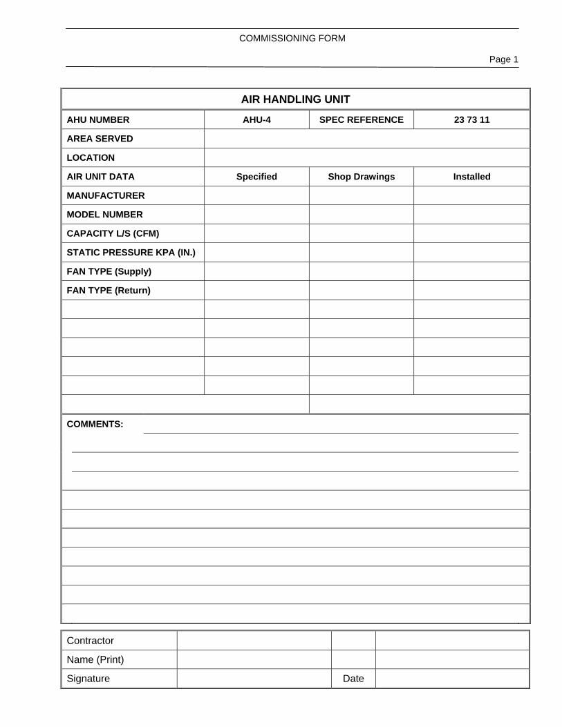
COMMISSIONING FORM
Page 1
Contractor
Name (Print)
Signature Date
AIR HANDLING UNIT
AHU NUMBER AHU-4 SPEC REFERENCE 23 73 11
AREA SERVED
LOCATION
AIR UNIT DATA Specified Shop Drawings Installed
MANUFACTURER
MODEL NUMBER
CAPACITY L/S (CFM)
STATIC PRESSURE KPA (IN.)
FAN TYPE (Supply)
FAN TYPE (Return)
COMMENTS:

COMMISSIONING FORM
Page 2
Contractor
Name (Print)
Signature Date
AIR HANDLING UNIT
AHU NUMBER AHU-4 SPEC REFERENCE 23 73 11
Pre Start-up Verification: YES NO N/A YES NO N/A
Ductwork installation complete Unit cleaned
Air filters installed Wiring complete
Filter gauges installed Abnormal vibrations
Lubrication complete Rotation correct
Speed drive installed Isolation working
Lights working Drains connnected
Identification tags match spec. Controls functional
Mfgr’s test sheets complete Test sheets attached
O/A damper closed with fan off Safeties function
COMMENTS:
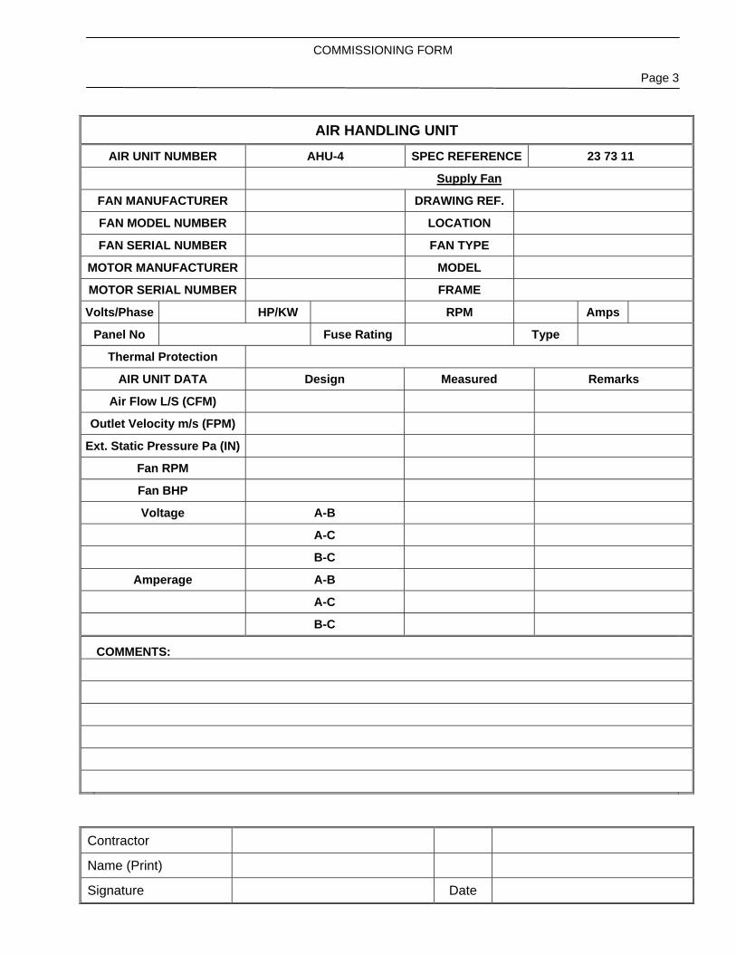
COMMISSIONING FORM
Page 3
Contractor
Name (Print)
Signature Date
AIR HANDLING UNIT AIR UNIT NUMBER AHU-4 SPEC REFERENCE 23 73 11
Supply Fan
FAN MANUFACTURER DRAWING REF.
FAN MODEL NUMBER LOCATION
FAN SERIAL NUMBER FAN TYPE
MOTOR MANUFACTURER MODEL
MOTOR SERIAL NUMBER FRAME
Volts/Phase HP/KW RPM Amps
Panel No Fuse Rating Type
Thermal Protection
AIR UNIT DATA Design Measured Remarks
Air Flow L/S (CFM)
Outlet Velocity m/s (FPM)
Ext. Static Pressure Pa (IN)
Fan RPM
Fan BHP
Voltage A-B
A-C
B-C
Amperage A-B
A-C
B-C
COMMENTS:

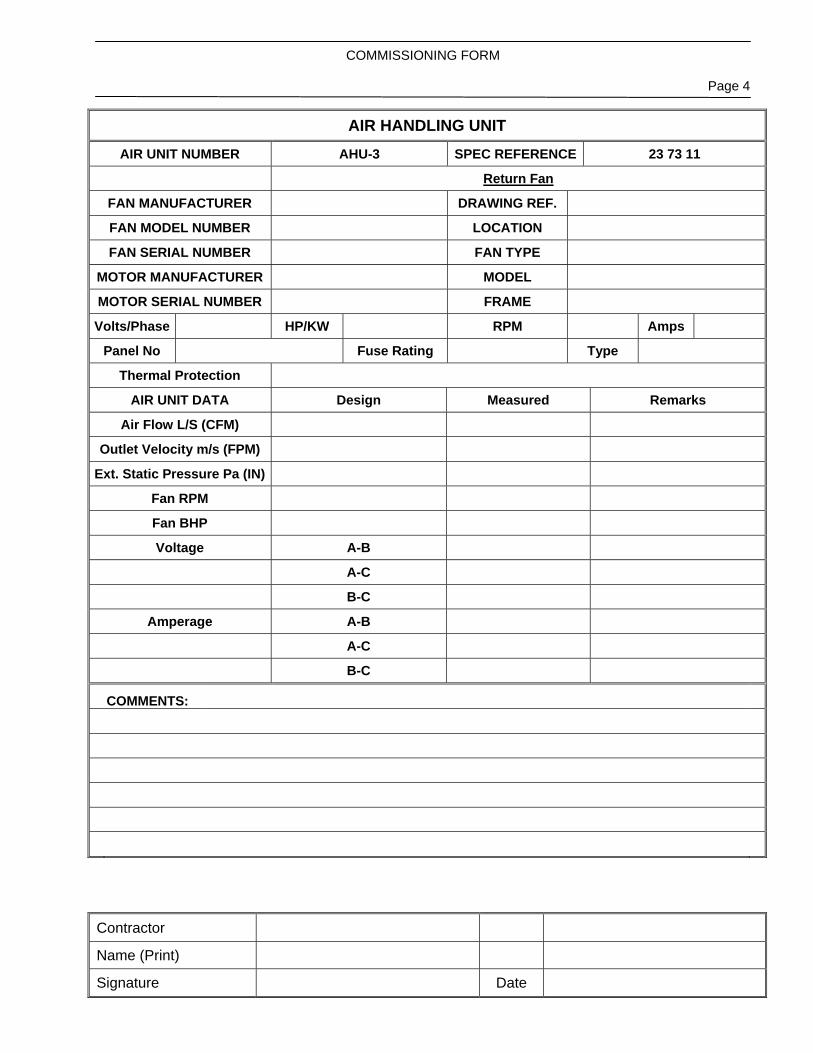
COMMISSIONING FORM
Page 4
Contractor
Name (Print)
Signature Date
AIR HANDLING UNIT AIR UNIT NUMBER AHU-4 SPEC REFERENCE 23 73 11
Return Fan
FAN MANUFACTURER DRAWING REF.
FAN MODEL NUMBER LOCATION
FAN SERIAL NUMBER FAN TYPE
MOTOR MANUFACTURER MODEL
MOTOR SERIAL NUMBER FRAME
Volts/Phase HP/KW RPM Amps
Panel No Fuse Rating Type
Thermal Protection
AIR UNIT DATA Design Measured Remarks
Air Flow L/S (CFM)
Outlet Velocity m/s (FPM)
Ext. Static Pressure Pa (IN)
Fan RPM
Fan BHP
Voltage A-B
A-C
B-C
Amperage A-B
A-C
B-C
COMMENTS:

COMMISSIONING FORM
Page 1
Contractor
Name (Print)
Signature Date
AIR HANDLING UNIT
AHU NUMBER AHU-3 SPEC REFERENCE 23 73 11
AREA SERVED
LOCATION
AIR UNIT DATA Specified Shop Drawings Installed
MANUFACTURER
MODEL NUMBER
CAPACITY L/S (CFM)
STATIC PRESSURE KPA (IN.)
FAN TYPE (Supply)
FAN TYPE (Return)
COMMENTS:

COMMISSIONING FORM
Page 2
Contractor
Name (Print)
Signature Date
AIR HANDLING UNIT
AHU NUMBER AHU-3 SPEC REFERENCE 23 73 11
Pre Start-up Verification: YES NO N/A YES NO N/A
Ductwork installation complete Unit cleaned
Air filters installed Wiring complete
Filter gauges installed Abnormal vibrations
Lubrication complete Rotation correct
Speed drive installed Isolation working
Lights working Drains connnected
Identification tags match spec. Controls functional
Mfgr’s test sheets complete Test sheets attached
O/A damper closed with fan off Safeties function
COMMENTS:

COMMISSIONING FORM
Page 3
Contractor
Name (Print)
Signature Date
AIR HANDLING UNIT AIR UNIT NUMBER AHU-3 SPEC REFERENCE 23 73 11
Supply Fan
FAN MANUFACTURER DRAWING REF.
FAN MODEL NUMBER LOCATION
FAN SERIAL NUMBER FAN TYPE
MOTOR MANUFACTURER MODEL
MOTOR SERIAL NUMBER FRAME
Volts/Phase HP/KW RPM Amps
Panel No Fuse Rating Type
Thermal Protection
AIR UNIT DATA Design Measured Remarks
Air Flow L/S (CFM)
Outlet Velocity m/s (FPM)
Ext. Static Pressure Pa (IN)
Fan RPM
Fan BHP
Voltage A-B
A-C
B-C
Amperage A-B
A-C
B-C
COMMENTS:
COMMISSIONING FORM
Page 4
Contractor
Name (Print)
Signature Date
AIR HANDLING UNIT AIR UNIT NUMBER AHU-3 SPEC REFERENCE 23 73 11
Return Fan
FAN MANUFACTURER DRAWING REF.
FAN MODEL NUMBER LOCATION
FAN SERIAL NUMBER FAN TYPE
MOTOR MANUFACTURER MODEL
MOTOR SERIAL NUMBER FRAME
Volts/Phase HP/KW RPM Amps
Panel No Fuse Rating Type
Thermal Protection
AIR UNIT DATA Design Measured Remarks
Air Flow L/S (CFM)
Outlet Velocity m/s (FPM)
Ext. Static Pressure Pa (IN)
Fan RPM
Fan BHP
Voltage A-B
A-C
B-C
Amperage A-B
A-C
B-C
COMMENTS:

COMMISSIONING FORM
Page 1
Contractor
Name (Print)
Signature Date
CIRCULATING PUMP
PUMP NUMBER PU-1 SPEC REFERENCE 23 21 23
SYSTEM SERVED
LOCATION
PUMP DATA Specified Shop Drawings Installed
MANUFACTURER
LIQUID
MODEL NUMBER
SIZE (suction x discharge)
CAPACITY L/S (GPM)
HEAD PRESSURE KPA (PSI)
TYPE
RPM
BHP
MOTOR KW (HP)
IMPELLER SIZE
VOLTS/PHASE
AMPS
COMMENTS:

COMMISSIONING FORM
Page 2
Contractor
Name (Print)
Signature Date
CIRCULATING PUMP
PUMP NUMBER PU-1 SPEC REFERENCE 23 21 23
YES NO N/A YES NO N/A
Piping Installation Complete Unit Cleaned
Pressure Gauges Installed Wiring Complete
Volute Venting Installed Abnormal Vibrations
Lubrication Complete Rotation Correct
Speed Drive Installed Packing Leaking
Strainers Installed Strainers Cleaned
Identification tags match spec. Controls functional
Mfgr’s test sheets complete Test sheets attached
COMMENTS:

COMMISSIONING FORM
Page 3
Contractor
Name (Print)
Signature Date
CIRCULATING PUMP PUMP NUMBER PU-1 SPEC REFERENCE 23 21 23
MOTOR MANUFACTURER MODEL
Volts/Phase HP/KW RMP
Amps Panel No Fuse Rating
Thermal Protection
MOTOR DATA Design Measured Remarks
Motor RPM
Voltage A-B
A-C
B-C
Amperage A-B
A-C
B-C
PUMP DATA
Flow L/S (GPM)
Head kPa (Feet)
Efficiency
Pump RPM
Outlet Velocity m/s (FPM)
COMMENTS:

COMMISSIONING FORM
Page 1
Contractor
Name (Print)
Signature Date
CIRCULATING PUMP
PUMP NUMBER PU-2 SPEC REFERENCE 23 21 23
SYSTEM SERVED
LOCATION
PUMP DATA Specified Shop Drawings Installed
MANUFACTURER
LIQUID
MODEL NUMBER
SIZE (suction x discharge)
CAPACITY L/S (GPM)
HEAD PRESSURE KPA (PSI)
TYPE
RPM
BHP
MOTOR KW (HP)
IMPELLER SIZE
VOLTS/PHASE
AMPS
COMMENTS:
COMMISSIONING FORM
Page 2
Contractor
Name (Print)
Signature Date
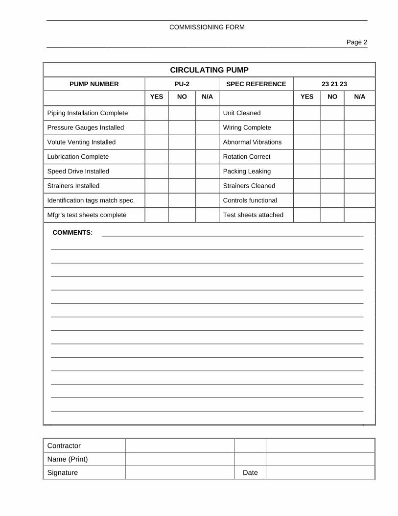
CIRCULATING PUMP
PUMP NUMBER PU-2 SPEC REFERENCE 23 21 23
YES NO N/A YES NO N/A
Piping Installation Complete Unit Cleaned
Pressure Gauges Installed Wiring Complete
Volute Venting Installed Abnormal Vibrations
Lubrication Complete Rotation Correct
Speed Drive Installed Packing Leaking
Strainers Installed Strainers Cleaned
Identification tags match spec. Controls functional
Mfgr’s test sheets complete Test sheets attached
COMMENTS:
COMMISSIONING FORM
Page 3
Contractor
Name (Print)
Signature Date
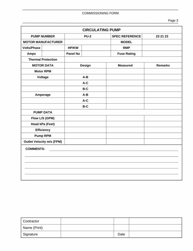
CIRCULATING PUMP PUMP NUMBER PU-2 SPEC REFERENCE 23 21 23
MOTOR MANUFACTURER MODEL
Volts/Phase HP/KW RMP
Amps Panel No Fuse Rating
Thermal Protection
MOTOR DATA Design Measured Remarks
Motor RPM
Voltage A-B
A-C
B-C
Amperage A-B
A-C
B-C
PUMP DATA
Flow L/S (GPM)
Head kPa (Feet)
Efficiency
Pump RPM
Outlet Velocity m/s (FPM)
COMMENTS:

COMMISSIONING FORM
Page 1
Contractor
Name (Print)
Signature Date
REHEAT COIL
REHEAT COIL NUMBER SPEC REFERENCE
SYSTEM SERVED
LOCATION
COIL DATA Specified Shop Drawings Installed
MANUFACTURER
HEATING SOURCE
AIR FLOW L/s (CFM)
SIZE MM (INCHES)
AIR VELOCITY MPM(FPM)
AIR P.D. kPa (PSI)
NO. OF ROWS
CAPACITY L/s (GPM)
WATER P. D. kPa (PSI)
COMMENTS:
COMMISSIONING FORM
Page 2
Contractor
Name (Print)
Signature Date
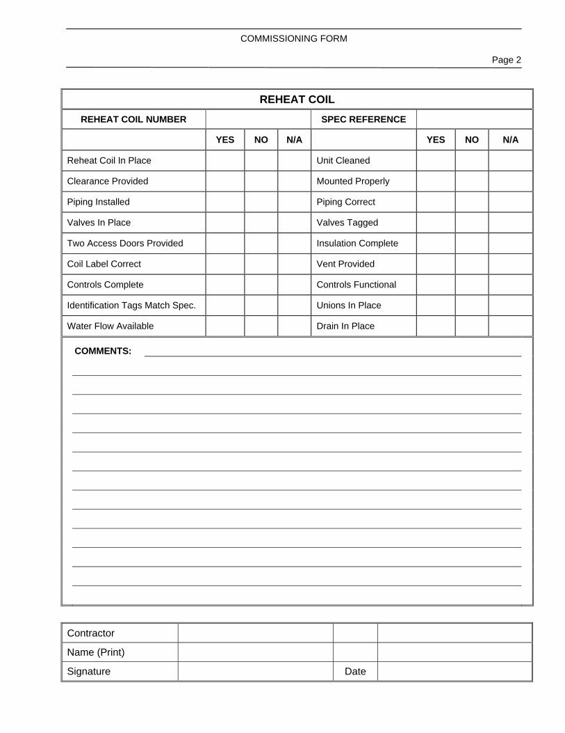
REHEAT COIL
REHEAT COIL NUMBER SPEC REFERENCE
YES NO N/A YES NO N/A
Reheat Coil In Place Unit Cleaned
Clearance Provided Mounted Properly
Piping Installed Piping Correct
Valves In Place Valves Tagged
Two Access Doors Provided Insulation Complete
Coil Label Correct Vent Provided
Controls Complete Controls Functional
Identification Tags Match Spec. Unions In Place
Water Flow Available Drain In Place
COMMENTS:
COMMISSIONING FORM
Page 3
Contractor
Name (Print)
Signature Date
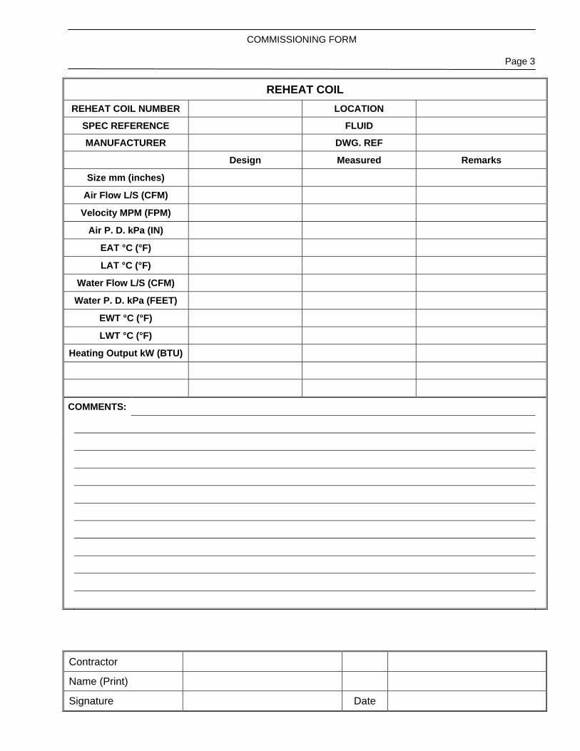
REHEAT COIL REHEAT COIL NUMBER LOCATION
SPEC REFERENCE FLUID
MANUFACTURER DWG. REF
Design Measured Remarks
Size mm (inches)
Air Flow L/S (CFM)
Velocity MPM (FPM)
Air P. D. kPa (IN)
EAT °C (°F)
LAT °C (°F)
Water Flow L/S (CFM)
Water P. D. kPa (FEET)
EWT °C (°F)
LWT °C (°F)
Heating Output kW (BTU)
COMMENTS:

COMMISSIONING FORM
Page 1
Contractor
Name (Print)
Signature Date
UNIT HEATER
UNIT HEATER NUMBER SPEC REFERENCE
SYSTEM SERVED
LOCATION
Specified Shop Drawings Installed
Manufacturer
Model
Heating Source
Air Flow L/S (Cfm)
Size Mm (Inches)
Weight
Water Flow L/S (Gpm)
Water P. D. kPa (Feet)
Heating Output kW (BTUH)
Fan Hp
Voltage
Amps
COMMENTS:
COMMISSIONING FORM
Page 2
Contractor
Name (Print)
Signature Date
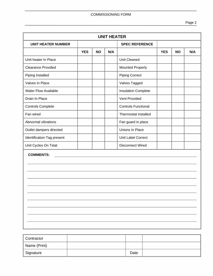
UNIT HEATER
UNIT HEATER NUMBER SPEC REFERENCE
YES NO N/A YES NO N/A
Unit heater In Place Unit Cleaned
Clearance Provided Mounted Properly
Piping Installed Piping Correct
Valves In Place Valves Tagged
Water Flow Available Insulation Complete
Drain In Place Vent Provided
Controls Complete Controls Functional
Fan wired Thermostat installed
Abnormal vibrations Fan guard in place
Outlet dampers directed Unions In Place
Identification Tag present Unit Label Correct
Unit Cycles On Tstat Disconnect Wired
COMMENTS:
COMMISSIONING FORM
Page 3
Contractor
Name (Print)
Signature Date
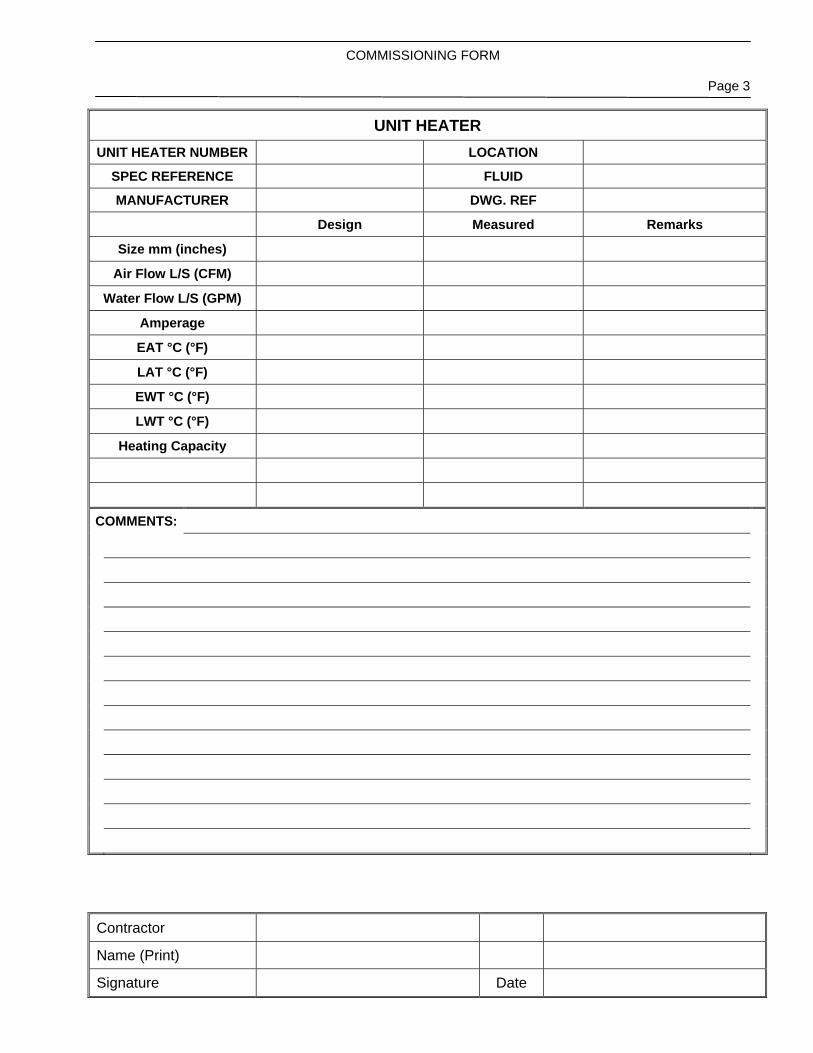
UNIT HEATER UNIT HEATER NUMBER LOCATION
SPEC REFERENCE FLUID
MANUFACTURER DWG. REF
Design Measured Remarks
Size mm (inches)
Air Flow L/S (CFM)
Water Flow L/S (GPM)
Amperage
EAT °C (°F)
LAT °C (°F)
EWT °C (°F)
LWT °C (°F)
Heating Capacity
COMMENTS:

Fort Rouge Leisure Centre Section 22 05 00 HVAC Upgrades – Phase 2 Page 1 of 1 Bid Opportunity No. 217-2012 March 2012
COMMON WORK RESULTS FOR PLUMBING
P:\Projects\2011\11-0107-02\Doc.Control\Issued\SOURCE\Docs\HVAC Upgrade Phase 2 FINAL SPEC\03-Plumbing\220500.doc
Part 1 General
1.1 SUBMITTALS .1 Submittals: in accordance with Section 01 33 00 - Submittal Procedures.
.2 Shop drawings to show:
.1 Mounting arrangements.
.2 Operating and maintenance clearances.
.3 Shop drawings and product data accompanied by:
.1 Detailed drawings of bases, supports, and anchor bolts.
.2 Acoustical sound power data, where applicable.
.3 Points of operation on performance curves.
.4 Manufacturer to certify current model production.
.5 Certification of compliance to applicable codes.
.4 Closeout Submittals:
.1 Provide operation and maintenance data for incorporation into manual specified in Section 01 78 00 - Closeout Submittals.
Part 2 Products
2.1 (Not Used)
Part 3 Execution
3.1 PAINTING REPAIRS AND RESTORATION .1 Prime and touch up marred finished paintwork to match original.
.2 Restore to new condition, finishes which have been damaged.
3.2 CLEANING .1 Clean interior and exterior of all systems including strainers. Vacuum interior of
ductwork and air handling units.
3.3 PROTECTION .1 Protect equipment and systems openings from dirt, dust, and other foreign materials
with materials appropriate to system.
END OF SECTION
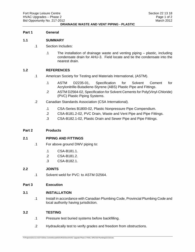
Fort Rouge Leisure Centre Section 22 13 18 HVAC Upgrades – Phase 2 Page 1 of 2 Bid Opportunity No. 217-2012 March 2012
DRAINAGE WASTE AND VENT PIPING - PLASTIC
P:\Projects\2011\11-0107-02\Doc.Control\Issued\SOURCE\Docs\HVAC Upgrade Phase 2 FINAL SPEC\03-Plumbing\221318.doc
Part 1 General
1.1 SUMMARY .1 Section Includes:
.1 The installation of drainage waste and venting piping – plastic, including condensate drain for AHU-3. Field locate and tie the condensate into the nearest drain.
1.2 REFERENCES
.1 American Society for Testing and Materials International, (ASTM).
.1 ASTM D2235-01, Specification for Solvent Cement for Acrylonitrille-Butadiene-Styrene (ABS) Plastic Pipe and Fittings.
.2 ASTM D2564-02, Specification for Solvent Cements for Poly(Vinyl-Chloride) (PVC) Plastic Piping Systems.
.2 Canadian Standards Association (CSA International).
.1 CSA-Series B1800-02, Plastic Nonpressure Pipe Compendium.
.2 CSA-B181.2-02, PVC Drain, Waste and Vent Pipe and Pipe Fittings.
.3 CSA-B182.1-02, Plastic Drain and Sewer Pipe and Pipe Fittings.
Part 2 Products
2.1 PIPING AND FITTINGS .1 For above ground DWV piping to:
.1 CSA-B181.1.
.2 CSA-B181.2.
.3 CSA-B182.1.
2.2 JOINTS .1 Solvent weld for PVC: to ASTM D2564.
Part 3 Execution
3.1 INSTALLATION .1 Install in accordance with Canadian Plumbing Code, Provincial Plumbing Code and
local authority having jurisdiction.
3.2 TESTING .1 Pressure test buried systems before backfilling.
.2 Hydraulically test to verify grades and freedom from obstructions.
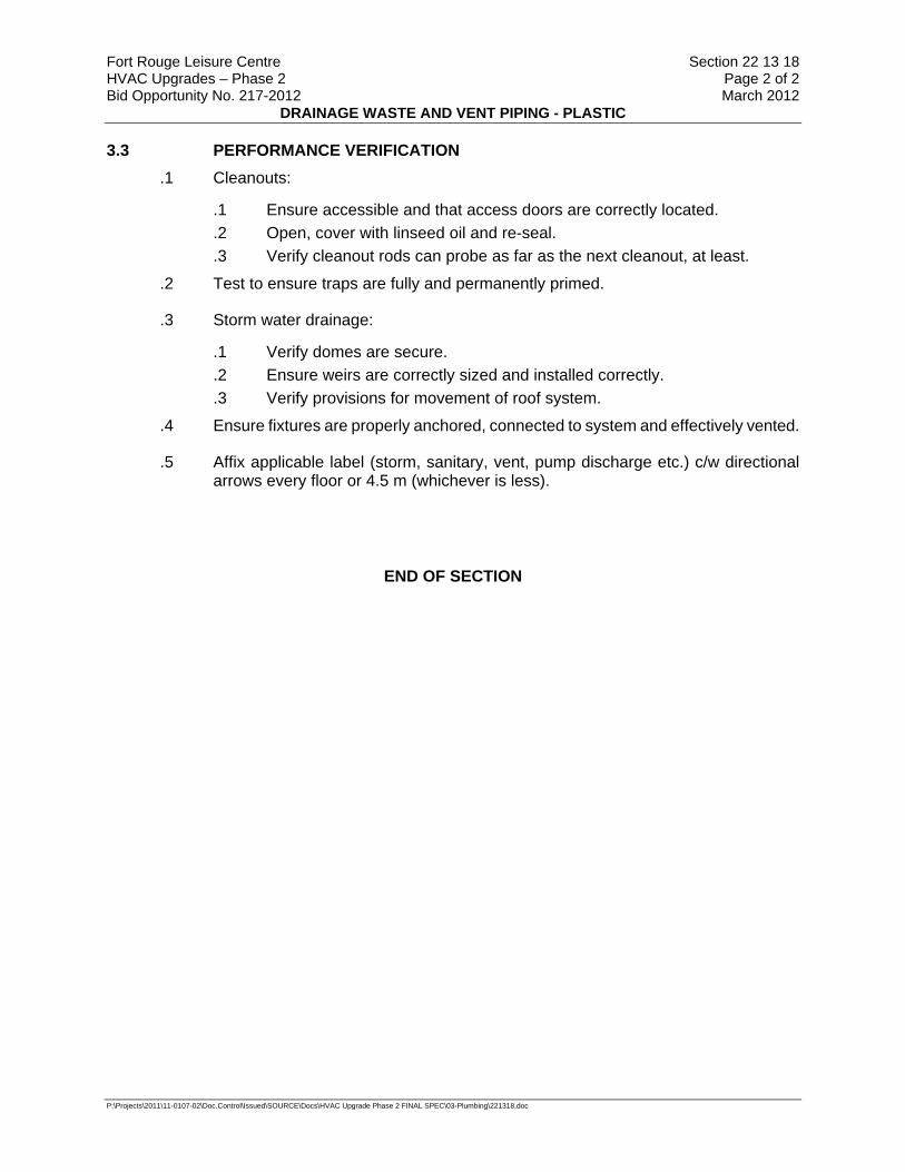
Fort Rouge Leisure Centre Section 22 13 18 HVAC Upgrades – Phase 2 Page 2 of 2 Bid Opportunity No. 217-2012 March 2012
DRAINAGE WASTE AND VENT PIPING - PLASTIC
P:\Projects\2011\11-0107-02\Doc.Control\Issued\SOURCE\Docs\HVAC Upgrade Phase 2 FINAL SPEC\03-Plumbing\221318.doc
3.3 PERFORMANCE VERIFICATION .1 Cleanouts:
.1 Ensure accessible and that access doors are correctly located.
.2 Open, cover with linseed oil and re-seal.
.3 Verify cleanout rods can probe as far as the next cleanout, at least.
.2 Test to ensure traps are fully and permanently primed.
.3 Storm water drainage:
.1 Verify domes are secure.
.2 Ensure weirs are correctly sized and installed correctly.
.3 Verify provisions for movement of roof system.
.4 Ensure fixtures are properly anchored, connected to system and effectively vented.
.5 Affix applicable label (storm, sanitary, vent, pump discharge etc.) c/w directional arrows every floor or 4.5 m (whichever is less).
END OF SECTION

Fort Rouge Leisure Centre Section 23 05 00 HVAC Upgrades – Phase 2 Page 1 of 3 Bid Opportunity No. 217-2012 March 2012
COMMON WORK RESULTS FOR HVAC
P:\Projects\2011\11-0107-02\Doc.Control\Issued\SOURCE\Docs\HVAC Upgrade Phase 2 FINAL SPEC\04-Mech\230500-CommonWorkResultsHVAC.doc
Part 1 General
1.1 SUBMITTALS .1 Submittals: in accordance with Section 01 33 00.
.2 Shop drawings to show:
.1 Mounting arrangements.
.2 Operating and maintenance clearances.
.3 Shop drawings and product data accompanied by:
.1 Detailed drawings of bases, supports, and anchor bolts.
.2 Acoustical sound power data, where applicable.
.3 Points of operation on performance curves.
.4 Manufacturer to certify current model production.
.5 Certification of compliance to applicable codes.
.4 Closeout Submittals:
.1 Provide operation and maintenance data for incorporation into manual specified in Section 01 78 00 - Closeout Submittals.
.2 Operation and maintenance manual approved by, and final copies deposited with, Contract Administrator before final inspection.
.3 Operation data to include: .1 Control schematics for systems including environmental controls. .2 Description of systems and their controls. .3 Description of operation of systems at various loads together with
reset schedules and seasonal variances. .4 Operation instruction for systems and component. .5 Description of actions to be taken in event of equipment failure. .6 Valves schedule and flow diagram. .7 Colour coding chart.
.4 Maintenance data to include: .1 Servicing, maintenance, operation and trouble-shooting instructions
for each item of equipment. .2 Data to include schedules of tasks, frequency, tools required and
task time. .5 Performance data to include:
.1 Equipment manufacturer's performance datasheets with point of operation as left after commissioning is complete.
.2 Equipment performance verification test results.
.3 Special performance data as specified.
.4 Testing, adjusting and balancing reports as specified in Section 23 05 93 - Testing, Adjusting and Balancing for HVAC.
Fort Rouge Leisure Centre Section 23 05 00 HVAC Upgrades – Phase 2 Page 2 of 3 Bid Opportunity No. 217-2012 March 2012
COMMON WORK RESULTS FOR HVAC
P:\Projects\2011\11-0107-02\Doc.Control\Issued\SOURCE\Docs\HVAC Upgrade Phase 2 FINAL SPEC\04-Mech\230500-CommonWorkResultsHVAC.doc
.6 Approvals: .1 Submit 1 copies of draft Operation and Maintenance Manual to
Contract Administrator for approval. Submission of individual data will not be accepted unless directed by Contract Administrator.
.2 Make changes as required and re-submit as directed by Contract Administrator.
.7 Additional data: .1 Prepare and insert into operation and maintenance manual
additional data when need for it becomes apparent during specified demonstrations and instructions.
.8 Site records: .1 Contract Administrator will provide 1 set of reproducible mechanical
drawings. Provide sets of white prints as required for each phase of work. Mark changes as work progresses and as changes occur.
.2 Transfer information weekly to reproducibles, revising reproducibles to show work as actually installed.
.3 Use different colour waterproof ink for each service.
.4 Make available for reference purposes and inspection. .9 As-built drawings:
.1 Prior to start of Testing, Adjusting and Balancing for HVAC, finalize production of as-built drawings.
.2 Identify each drawing in lower right hand corner in letters at least 12 mm high as follows: - "AS BUILT DRAWINGS: THIS DRAWING HAS BEEN REVISED TO SHOW MECHANICAL SYSTEMS AS INSTALLED" (Signature of Contractor) (Date).
.3 Submit to Contract Administrator for approval and make corrections as directed.
.4 Perform testing, adjusting and balancing for HVAC using as-built drawings.
.5 Submit completed reproducible as-built drawings with Operating and Maintenance Manuals.
.10 Submit copies of as-built drawings for inclusion in final TAB report.
1.2 MAINTENANCE
.1 Provide one set of special tools required to service equipment as recommended by manufacturers and in accordance with Section 01 78 00 - Closeout Submittals.
.2 Furnish one commercial quality grease gun, grease and adapters to suit different types of grease and grease fittings.

Fort Rouge Leisure Centre Section 23 05 00 HVAC Upgrades – Phase 2 Page 3 of 3 Bid Opportunity No. 217-2012 March 2012
COMMON WORK RESULTS FOR HVAC
P:\Projects\2011\11-0107-02\Doc.Control\Issued\SOURCE\Docs\HVAC Upgrade Phase 2 FINAL SPEC\04-Mech\230500-CommonWorkResultsHVAC.doc
Part 2 Products (Not Used)
Part 3 Execution
3.1 PAINTING REPAIRS AND RESTORATION .1 Prime and touch up marred finished paintwork to match original.
.2 Restore to new condition, finishes which have been damaged.
3.2 CLEANING .1 Clean interior and exterior of all systems. Vacuum interior of ductwork and air
handling units.
3.3 FIELD QUALITY CONTROL
.1 Manufacturer's Field Services:
.1 Obtain written report from manufacturer verifying compliance of Work, in handling, installing, applying, protecting and cleaning of product and submit Manufacturer's Field Reports as described in PART 1 - SUBMITTALS.
.2 Provide manufacturer's field services consisting of product use recommendations and periodic site visits for inspection of product installation in accordance with manufacturer's instructions.
3.4 DEMONSTRATION .1 Contract Administrator will use equipment and systems for test purposes prior to
acceptance. Supply labour, material, and instruments required for testing.
.2 Supply tools, equipment and personnel to demonstrate and instruct operating and maintenance personnel in operating, controlling, adjusting, trouble-shooting and servicing of all systems and equipment during regular work hours, prior to acceptance.
.3 Use operation and maintenance manual, as-built drawings, and audio visual aids as part of instruction materials.
.4 Instruction duration time requirements as specified in appropriate sections.
.5 Contract Administrator will record these demonstrations on video tape for future reference.
3.5 PROTECTION .1 Protect equipment and systems openings from dirt, dust, and other foreign materials
with materials appropriate to system.
END OF SECTION

Fort Rouge Leisure Centre Section 23 05 01 HVAC Upgrades – Phase 2 Page 1 of 1 Bid Opportunity No. 217-2012 March 2012
USE OF HVAC SYSTEMS DURING CONSTRUCTION
P:\Projects\2011\11-0107-02\Doc.Control\Issued\SOURCE\Docs\HVAC Upgrade Phase 2 FINAL SPEC\04-Mech\230501-ExistingHVAC Use.doc
Part 1 General
1.1 SUMMARY .1 Section Includes:
.1 Use of mechanical systems during construction.
1.2 USE OF SYSTEMS .1 Use of new and/or existing permanent heating and ventilating systems for supplying
temporary heat or ventilation is permitted only under following conditions:
.1 Entire system is complete, pressure tested, cleaned, flushed out.
.2 Building has been closed in, areas to be heated/ventilated are clean and will not thereafter be subjected to dust-producing processes.
.3 There is no possibility of damage.
.4 Supply ventilation systems are protected by 60% filters, inspected daily, changed every week or more frequently as required.
.5 Return systems have approved filters over openings, inlets, outlets.
.6 Systems will be: .1 Operated as per manufacturer's recommendations and instructions. .2 Operated by Contractor. .3 Monitored continuously by Contractor.
.7 Warranties and guarantees are not relaxed.
.8 Regular preventive and other manufacturers recommended maintenance routines are performed by Contractor at own expense and under supervision of Contract Administrator.
.9 Refurbish entire system before static completion; clean internally and externally, restore to "as- new" condition, replace filters in air systems.
.2 Filters specified in this Section are over and above those specified in other Sections of this project.
.3 Exhaust systems are not included in approvals for temporary heating ventilation.
Part 2 Products
2.1 NOT USED .1
Part 3 Execution
3.1 NOT USED
END OF SECTION
Fort Rouge Leisure Centre Section 23 05 13 HVAC Upgrades – Phase 2 Page 1 of 3 Bid Opportunity No. 217-2012 March 2012
COMMON MOTOR REQUIREMENTS FOR HVAC EQUIPMENT
P:\Projects\2011\11-0107-02\Doc.Control\Issued\SOURCE\Docs\HVAC Upgrade Phase 2 FINAL SPEC\04-Mech\230513-CommonMotorRequirements.doc
Part 1 General
1.1 SUMMARY .1 Section Includes:
.1 Electrical motors, drives and guards for mechanical equipment and systems.
.2 Supplier and installer responsibility indicated in Motor, Control and Equipment Schedule on electrical drawings and related mechanical responsibility is indicated on Mechanical Equipment Schedule on mechanical drawings.
.3 Control wiring and conduit is specified in Division 26 except for conduit, wiring and connections below 50 V which are related to control systems specified in Division 22 and 23. Refer to Division 26 for quality of materials and workmanship.
.4 Sustainable requirements for construction and verification.
1.2 REFERENCES .1 American Society of Heating, Refrigeration and Air-Conditioning Engineers
(ASHRAE)
.1 ASHRAE 90.1-[01], Energy Standard for Buildings Except Low-Rise Residential Buildings (IESNA cosponsored; ANSI approved; Continuous Maintenance Standard).
.2 Electrical Equipment Manufacturers' Association Council (EEMAC)
.3 Health Canada/Workplace Hazardous Materials Information System (WHMIS)
.1 Material Safety Data Sheets (MSDS).
1.3 SUBMITTALS .1 Submittals: in accordance with Section 01 33 00 - Submittal Procedures.
.2 Product Data:
.1 Submit manufacturer's printed product literature, specifications and datasheet in accordance with Section 01 33 00 - Submittal Procedures. Include product characteristics, performance criteria, and limitations.
.3 Closeout Submittals
.1 Provide maintenance data for motors, drives and guards for incorporation into manual specified in Section 01 78 00 - Closeout Submittals.
Part 2 Products
2.1 GENERAL .1 Motors: high efficiency, in accordance with local Hydro company standards and to
ASHRAE 90.1.

Fort Rouge Leisure Centre Section 23 05 13 HVAC Upgrades – Phase 2 Page 2 of 3 Bid Opportunity No. 217-2012 March 2012
COMMON MOTOR REQUIREMENTS FOR HVAC EQUIPMENT
P:\Projects\2011\11-0107-02\Doc.Control\Issued\SOURCE\Docs\HVAC Upgrade Phase 2 FINAL SPEC\04-Mech\230513-CommonMotorRequirements.doc
2.2 MOTORS .1 Provide motors for mechanical equipment as specified.
.2 Motors under 373 W (1/2 HP): speed as indicated, continuous duty, built-in overload protection, resilient mount, single phase, 120 V, unless otherwise specified or indicated.
.3 Motors 373 W (1/2 HP) and larger: EEMAC Class B, squirrel cage induction, speed as indicated, continuous duty, drip proof, ball bearing, maximum temperature rise 40 degrees C, 3 phase, unless otherwise indicated.
2.3 TEMPORARY MOTORS .1 If delivery of specified motor will delay completion or commissioning work, install
motor approved by Contract Administrator for temporary use. Work will only be accepted when specified motor is installed.
2.4 BELT DRIVES .1 Fit reinforced belts in sheave matched to drive. Multiple belts to be matched sets.
.2 Use cast iron or steel sheaves secured to shafts with removable keys unless otherwise indicated.
.3 For motors under 7.5 kW (10 HP): standard adjustable pitch drive sheaves, having plus or minus 10% range. Use mid-position of range for specified r/min.
.4 For motors 7.5 kW (10 HP) and over: sheave with split tapered bushing and keyway having fixed pitch unless specifically required for item concerned. Provide sheave of correct size to suit balancing.
.5 Correct size of sheave determined during commissioning.
.6 Minimum drive rating: 1.5 times nameplate rating on motor. Keep overhung loads within manufacturer's design requirements on prime mover shafts.
.7 Motor slide rail adjustment plates to allow for centre line adjustment.
.8 Supply one set of spare belts for each set installed in accordance with Section 01 78 00 - Closeout Submittals.
2.5 DRIVE GUARDS .1 Provide guards for unprotected drives.
.2 Guards for belt drives;
.1 Expanded metal screen welded to steel frame.
.2 Minimum 1.2 mm thick sheet metal tops and bottoms.
.3 38 mm dia holes on both shaft centres for insertion of tachometer.
.4 Removable for servicing.

Fort Rouge Leisure Centre Section 23 05 13 HVAC Upgrades – Phase 2 Page 3 of 3 Bid Opportunity No. 217-2012 March 2012
COMMON MOTOR REQUIREMENTS FOR HVAC EQUIPMENT
P:\Projects\2011\11-0107-02\Doc.Control\Issued\SOURCE\Docs\HVAC Upgrade Phase 2 FINAL SPEC\04-Mech\230513-CommonMotorRequirements.doc
.3 Provide means to permit lubrication and use of test instruments with guards in place.
.4 Install belt guards to allow movement of motors for adjusting belt tension.-
.5 Guard for flexible coupling:
.1 "U" shaped, minimum 1.6 mm thick galvanized mild steel.
.2 Securely fasten in place.
.3 Removable for servicing.
.6 Unprotected fan inlets or outlets:
.1 Wire or expanded metal screen, galvanized, 19 mm mesh.
.2 Net free area of guard: not less than 80% of fan openings.
.3 Securely fasten in place.
.4 Removable for servicing.
Part 3 Execution
3.1 MANUFACTURER'S INSTRUCTIONS .1 Compliance: comply with manufacturer's written recommendations or specifications,
including product technical bulletins, handling, storage and installation instructions, and datasheet.
3.2 INSTALLATION .1 Fasten securely in place.
.2 Make removable for servicing, easily returned into, and positively in position.
3.3 CLEANING .1 Upon completion and verification of performance of installation, remove surplus
materials, excess materials, rubbish, tools and equipment.
END OF SECTION

Fort Rouge Leisure Centre Section 23 05 21 HVAC Upgrades – Phase 2 Page 1 of 4 Bid Opportunity No. 217-2012 March 2012
THERMOMETERS AND PRESSURE GAUGES - PIPING SYSTEMS
P:\Projects\2011\11-0107-02\Doc.Control\Issued\SOURCE\Docs\HVAC Upgrade Phase 2 FINAL SPEC\04-Mech\230521-Thermometers.doc
□
Part 1 General
1.1 SECTION INCLUDES .1 Materials and installation for thermometers and pressure gauges in piping systems.
1.2 REFERENCES .1 American Society of Mechanical Engineers (ASME).
.1 ASME B40.100-[01], Pressure Gauges and Gauge Attachments.
.2 ASME B40.200-[01], Thermometers, Direct Reading and Remote Reading.
.2 Canadian General Standards Board (CGSB).
.1 CAN/CGSB-14.4-[M88], Thermometers, Liquid-in-Glass, Self Indicating, Commercial/Industrial Type.
.2 CAN/CGSB-14.5-[M88], Thermometers, Bimetallic, Self-Indicating, Commercial/Industrial Type.
1.3 SUBMITTALS .1 Submittals in accordance with Section 01 33 00 - Submittal Procedures.
.2 Submit shop drawings and product data.
.3 Submit manufacturer's product data for following items:
.1 Thermometers.
.2 Pressure gauges.
.3 Stop cocks.
.4 Syphons.
.5 Wells. Part 2 Products
2.1 GENERAL .1 Design point to be at mid point of scale or range.
.2 Ranges: as indicated.
2.2 DIRECT READING THERMOMETERS .1 Industrial, variable angle type, liquid filled, 125 mm scale length: to CAN/CGSB14.4.
2.3 REMOTE READING THERMOMETERS .1 100 mm diameter mercury-free liquid filled vapour activated dial type: to
CAN/CGSB-14.5, accuracy within one scale division, brass movement, stainless steel capillary, stainless steel spiral armour, stainless steel bulb and polished stainless steel case for wall mounting.

Fort Rouge Leisure Centre Section 23 05 21 HVAC Upgrades – Phase 2 Page 2 of 4 Bid Opportunity No. 217-2012 March 2012
THERMOMETERS AND PRESSURE GAUGES - PIPING SYSTEMS
P:\Projects\2011\11-0107-02\Doc.Control\Issued\SOURCE\Docs\HVAC Upgrade Phase 2 FINAL SPEC\04-Mech\230521-Thermometers.doc
□
2.4 THERMOMETER WELLS .1 Copper pipe: copper or bronze.
.2 Steel pipe: brass or stainless steel.
2.5 PRESSURE GAUGES .1 112 mm, dial type: to ASME B40.100, Grade 2A, stainless steel bourdon tube
having 0.5% accuracy full scale unless otherwise specified.
.2 Provide:
.1 Siphon for steam service.
.2 Snubber for pulsating operation.
.3 Diaphragm assembly for corrosive service.
.4 Gasketted pressure relief back with solid front.
.5 Bronze stop cock.
.6 Oil filled for high vibration applications.
Part 3 Execution
3.1 GENERAL .1 Install so they can be easily read from floor or platform. If this cannot be
accomplished, install remote reading units.
.2 Install between equipment and first fitting or valve.
3.2 THERMOMETERS .1 Install in wells on piping. Provide heat conductive material inside well.
.2 Install in locations as indicated.
.3 Use extensions where thermometers are installed through insulation.
3.3 PRESSURE GAUGES .1 Install in following locations:
.1 Suction and discharge of pumps.
.2 Outlet of boilers.
.3 In other locations as indicated.
.2 Install gauge cocks for balancing purposes, elsewhere.
.3 Use extensions where pressure gauges are installed through insulation.
3.4 NAMEPLATES .1 Install engraved lamicoid nameplates as specified in Section 23 05 54 - Mechanical
Identification, identifying medium.
END OF SECTION

Fort Rouge Leisure Centre Section 23 05 29 HVAC Upgrades – Phase 2 Page 1 of 6 Bid Opportunity No. 217-2012 March 2012
HANGERS AND SUPPORTS FOR HVAC PIPING AND EQUIPMENT
P:\Projects\2011\11-0107-02\Doc.Control\Issued\SOURCE\Docs\HVAC Upgrade Phase 2 FINAL SPEC\04-Mech\230529-Hangers and Supports.doc
Part 1 General
1.1 SUMMARY .1 Section Includes:
.1 Concrete housekeeping pads, hangers and supports for mechanical piping, ducting and equipment.
1.2 REFERENCES .1 American National Standards Institute/American Society of Mechanical Engineers
(ANSI/ASME)
.1 ANSI/ASME B31.1-04, Power Piping.
.2 American Society for Testing and Materials International (ASTM)
.1 ASTM A125-1996(R2001), Specification for Steel Springs, Helical, Heat-Treated.
.2 ASTM A307-04, Specification for Carbon Steel Bolts and Studs, 60,000 PSI Tensile Strength.
.3 ASTM A563-04a, Specification for Carbon and Alloy Steel Nuts.
.3 Factory Mutual (FM)
.4 Health Canada/Workplace Hazardous Materials Information System (WHMIS)
.1 Material Safety Data Sheets (MSDS).
.5 Manufacturer's Standardization Society of the Valves and Fittings Industry (MSS)
.1 MSS SP58-2002, Pipe Hangers and Supports - Materials, Design and Manufacture.
.2 ANSI/MSS SP69-2003, Pipe Hangers and Supports - Selection and Application.
.3 MSS SP89-2003, Pipe Hangers and Supports - Fabrication and Installation Practices.
.6 Underwriter's Laboratories of Canada (ULC)
1.3 SYSTEM DESCRIPTION .1 Design Requirements:
.1 Construct pipe hanger and support to manufacturer's recommendations utilizing manufacturer's regular production components, parts and assemblies.
.2 Base maximum load ratings on allowable stresses prescribed by ASME B31.1 or MSS SP58.
.3 Ensure that supports, guides, anchors do not transmit excessive quantities of heat to building structure.
.4 Design hangers and supports to support systems under conditions of operation, allow free expansion and contraction, prevent excessive stresses from being introduced into pipework or connected equipment.

Fort Rouge Leisure Centre Section 23 05 29 HVAC Upgrades – Phase 2 Page 2 of 6 Bid Opportunity No. 217-2012 March 2012
HANGERS AND SUPPORTS FOR HVAC PIPING AND EQUIPMENT
P:\Projects\2011\11-0107-02\Doc.Control\Issued\SOURCE\Docs\HVAC Upgrade Phase 2 FINAL SPEC\04-Mech\230529-Hangers and Supports.doc
.5 Provide for vertical adjustments after erection and during commissioning. Amount of adjustment in accordance with MSS SP58.
1.4 SUBMITTALS .1 Submittals: in accordance with Section 01 33 00 - Submittal Procedures.
.2 Submit shop drawings and product data for following items:
.1 Bases, hangers and supports.
.2 Connections to equipment and structure.
.3 Structural assemblies.
.3 Closeout Submittals:
.1 Provide maintenance data for incorporation into manual specified in Section 01 78 00 - Closeout Submittals.
1.5 DELIVERY, STORAGE, AND HANDLING .1 Packing, shipping, handling and unloading:
.1 Deliver, store and handle materials in accordance with manufacturer's written instructions.
Part 2 Products
2.1 GENERAL .1 Fabricate hangers, supports and sway braces in accordance with ANSI B31.1 and
MSS SP58.
.2 Use components for intended design purpose only. Do not use for rigging or erection purposes.
2.2 PIPE HANGERS .1 Finishes:
.1 Pipe hangers and supports: galvanized.
.2 Use electro-plating galvanizing process or hot dipped galvanizing process.
.3 Ensure steel hangers in contact with copper piping are copper plated.
.2 Upper attachment structural: suspension from lower flange of I-Beam:
.1 Cold piping NPS 2 maximum: malleable iron C-clamp with hardened steel cup point setscrew, locknut and carbon steel retaining clip. .1 Rod: 9 mm UL listed.
.2 Cold piping NPS 2 1/2 or greater, hot piping: malleable iron beam clamp, eye rod, jaws and extension with carbon steel retaining clip, tie rod, nuts and washers, UL listed to MSS-SP58 and MSS-SP69.
Fort Rouge Leisure Centre Section 23 05 29 HVAC Upgrades – Phase 2 Page 3 of 6 Bid Opportunity No. 217-2012 March 2012
HANGERS AND SUPPORTS FOR HVAC PIPING AND EQUIPMENT
P:\Projects\2011\11-0107-02\Doc.Control\Issued\SOURCE\Docs\HVAC Upgrade Phase 2 FINAL SPEC\04-Mech\230529-Hangers and Supports.doc
.3 Upper attachment structural: suspension from upper flange of I-Beam:
.1 Cold piping NPS 2 maximum: ductile iron top-of-beam C-clamp with hardened steel cup point setscrew, locknut and carbon steel retaining clip, UL listed to MSS SP69.
.2 Cold piping NPS 2 1/2 or greater, hot piping: malleable iron top-of-beam jaw-clamp with hooked rod, spring washer, plain washer and nut UL listed.
.4 Upper attachment to concrete:
.1 Ceiling: carbon steel welded eye rod, clevis plate, clevis pin and cotters with weldless forged steel eye nut. Ensure eye 6 mm minimum greater than rod diameter.
.2 Concrete inserts: wedge shaped body with knockout protector plate UL listed to MSS SP69.
.5 Hanger rods: threaded rod material to MSS SP58:
.1 Ensure that hanger rods are subject to tensile loading only.
.2 Provide linkages where lateral or axial movement of pipework is anticipated.
.6 Pipe attachments: material to MSS SP58:
.1 Attachments for steel piping: carbon steel galvanized.
.2 Attachments for copper piping: copper plated black steel.
.3 Use insulation shields for hot pipework.
.4 Oversize pipe hangers and supports.
.7 Adjustable clevis: material to MSS SP69 UL listed, clevis bolt with nipple spacer and vertical adjustment nuts above and below clevis.
.8 Yoke style pipe roll: carbon steel yoke, rod and nuts with cast iron roll, to MSS SP69.
.9 U-bolts: carbon steel to MSS SP69 with 2 nuts at each end to ASTM A563.
.1 Finishes for steel pipework: galvanized.
.2 Finishes for copper, glass, brass or aluminum pipework: galvanized, with formed portion plastic coated.
.10 Pipe rollers: cast iron roll and roll stand with carbon steel rod to MSS SP69.
2.3 RISER CLAMPS .1 Steel or cast iron pipe: galvanized carbon steel to MSS SP58, type 42, UL listed.
.2 Copper pipe: carbon steel copper plated to MSS SP58, type 42.
.3 Bolts: to ASTM A307.
.4 Nuts: to ASTM A563.
Fort Rouge Leisure Centre Section 23 05 29 HVAC Upgrades – Phase 2 Page 4 of 6 Bid Opportunity No. 217-2012 March 2012
HANGERS AND SUPPORTS FOR HVAC PIPING AND EQUIPMENT
P:\Projects\2011\11-0107-02\Doc.Control\Issued\SOURCE\Docs\HVAC Upgrade Phase 2 FINAL SPEC\04-Mech\230529-Hangers and Supports.doc
2.4 INSULATION PROTECTION SHIELDS .1 Insulated cold piping:
.1 64 kg/m3 density insulation plus insulation protection shield to: MSS SP69, galvanized sheet carbon steel. Length designed for maximum 3 m span.
.2 Insulated hot piping:
.1 Curved plate 300 mm long, with edges turned up, welded-in centre plate for pipe sizes NPS 12 and over, carbon steel to comply with MSS SP69.
2.5 CONSTANT SUPPORT SPRING HANGERS .1 Springs: alloy steel to ASTM A125, shot peened, magnetic particle inspected, with
+/-5% spring rate tolerance, tested for free height, spring rate, loaded height and provided with Certified Mill Test Report (CMTR).
.2 Load adjustability: 10 % minimum adjustability each side of calibrated load. Adjustment without special tools. Adjustments not to affect travel capabilities.
.3 Provide upper and lower factory set travel stops.
.4 Provide load adjustment scale for field adjustments.
.5 Total travel to be actual travel + 20%. Difference between total travel and actual travel 25 mm minimum.
.6 Individually calibrated scales on each side of support calibrated prior to shipment, complete with calibration record.
2.6 EQUIPMENT ANCHOR BOLTS AND TEMPLATES .1 Provide templates to ensure accurate location of anchor bolts.
2.7 HOUSE-KEEPING PADS .1 Provide 100 mm high concrete housekeeping pads for base-mounted equipment;
size pads 50 mm larger than equipment; chamfer pad edges.
Part 3 Execution
3.1 MANUFACTURER'S INSTRUCTIONS .1 Compliance: comply with manufacturer's written recommendations or specifications,
including product technical bulletins, handling, storage and installation instructions, and datasheet.
3.2 INSTALLATION .1 Install in accordance with:
.1 manufacturer's instructions and recommendations.

Fort Rouge Leisure Centre Section 23 05 29 HVAC Upgrades – Phase 2 Page 5 of 6 Bid Opportunity No. 217-2012 March 2012
HANGERS AND SUPPORTS FOR HVAC PIPING AND EQUIPMENT
P:\Projects\2011\11-0107-02\Doc.Control\Issued\SOURCE\Docs\HVAC Upgrade Phase 2 FINAL SPEC\04-Mech\230529-Hangers and Supports.doc
.2 Vibration Control Devices:
.1 Install on piping systems at pumps, boilers, chillers, cooling towers, and as indicated.
.3 Clamps on riser piping:
.1 Support independent of connected horizontal pipework using riser clamps and riser clamp lugs welded to riser.
.2 Bolt-tightening torques to industry standards.
.3 Steel pipes: install below coupling or shear lugs welded to pipe.
.4 Cast iron pipes: install below joint.
.4 Clevis plates:
.1 Attach to concrete with 4minimum concrete inserts, one at each corner.
.5 Provide supplementary structural steelwork where structural bearings do not exist or where concrete inserts are not in correct locations.
.6 Use approved constant support type hangers where:
.1 vertical movement of pipework is 13 mm or more,
.2 transfer of load to adjacent hangers or connected equipment is not permitted.
.7 Use variable support spring hangers where:
.1 transfer of load to adjacent piping or to connected equipment is not critical.
.2 variation in supporting effect does not exceed 25 % of total load.
3.3 HANGER SPACING .1 Fire protection: to applicable fire code.
.2 Gas and fuel oil piping: up to NPS 1/2: every 1.8 m.
.3 Copper piping: up to NPS 1/2: every 1.5 m.
.4 Flexible joint roll groove pipe: in accordance with table below, but not less than one hanger at joints.
.5 Within 300 mm of each elbow.
Maximum Pipe Size : NPS Maximum Spacing Steel Maximum Spacing Copper up to 1-1/4 2.1 m 1.8 m 1-1/2 2.7 m 2.4 m 2 3.0 m 2.7 m 2-1/2 3.6 m 3.0 m 3 3.6 m 3.0 m 3-1/2 3.9 m 3.3 m 4 4.2 m 3.6 m 5 4.8 m
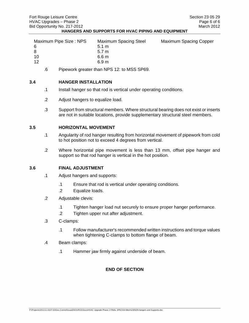
Fort Rouge Leisure Centre Section 23 05 29 HVAC Upgrades – Phase 2 Page 6 of 6 Bid Opportunity No. 217-2012 March 2012
HANGERS AND SUPPORTS FOR HVAC PIPING AND EQUIPMENT
P:\Projects\2011\11-0107-02\Doc.Control\Issued\SOURCE\Docs\HVAC Upgrade Phase 2 FINAL SPEC\04-Mech\230529-Hangers and Supports.doc
Maximum Pipe Size : NPS Maximum Spacing Steel Maximum Spacing Copper 6 5.1 m 8 5.7 m 10 6.6 m 12 6.9 m
.6 Pipework greater than NPS 12: to MSS SP69.
3.4 HANGER INSTALLATION .1 Install hanger so that rod is vertical under operating conditions.
.2 Adjust hangers to equalize load.
.3 Support from structural members. Where structural bearing does not exist or inserts are not in suitable locations, provide supplementary structural steel members.
3.5 HORIZONTAL MOVEMENT .1 Angularity of rod hanger resulting from horizontal movement of pipework from cold
to hot position not to exceed 4 degrees from vertical.
.2 Where horizontal pipe movement is less than 13 mm, offset pipe hanger and support so that rod hanger is vertical in the hot position.
3.6 FINAL ADJUSTMENT .1 Adjust hangers and supports:
.1 Ensure that rod is vertical under operating conditions.
.2 Equalize loads.
.2 Adjustable clevis:
.1 Tighten hanger load nut securely to ensure proper hanger performance.
.2 Tighten upper nut after adjustment.
.3 C-clamps:
.1 Follow manufacturer's recommended written instructions and torque values when tightening C-clamps to bottom flange of beam.
.4 Beam clamps:
.1 Hammer jaw firmly against underside of beam.
END OF SECTION

Fort Rouge Leisure Centre Section 23 05 54 HVAC Upgrades – Phase 2 Page 1 of 4 Bid Opportunity No. 217-2012 March 2012
MECHANICAL IDENTIFICATION
P:\Projects\2011\11-0107-02\Doc.Control\Issued\SOURCE\Docs\HVAC Upgrade Phase 2 FINAL SPEC\04-Mech\230554-MechID.doc
Part 1 General
1.1 SUMMARY .1 Section Includes:
.1 Materials and requirements for the identification of piping systems, duct work, valves and controllers, including the installation and location of identification systems.
1.2 REFERENCES
.1 Canadian Gas Association (CGA)
.1 CSA/CGA B149.1-05, Natural Gas and Propane Installation Code.
.2 Canadian General Standards Board (CGSB)
.1 CAN/CGSB-1.60-97, Interior Alkyd Gloss Enamel.
.2 CAN/CGSB-24.3-92, Identification of Piping Systems.
.3 National Fire Protection Association (NFPA)
.1 NFPA 13-2002, Standard for the Installation of Sprinkler Systems.
.2 NFPA 14-2003, Standard for the Installation of Standpipe and Hose Systems.
1.3 SUBMITTALS .1 Product Data:
.2 Submittals: in accordance Section 01 33 00 - Submittal Procedures.
.3 Product data to include paint colour chips, other products specified in this section.
Part 2 Products
2.1 MANUFACTURER'S EQUIPMENT NAMEPLATES .1 Metal or plastic laminate nameplate mechanically fastened to each piece of
equipment by manufacturer.
.2 Lettering and numbers raised or recessed.
.3 Information to include, as appropriate:
.1 Equipment: manufacturer's name, model, size, serial number, capacity.
.2 Motor: voltage, Hz, phase, power factor, duty, frame size.

Fort Rouge Leisure Centre Section 23 05 54 HVAC Upgrades – Phase 2 Page 2 of 4 Bid Opportunity No. 217-2012 March 2012
MECHANICAL IDENTIFICATION
P:\Projects\2011\11-0107-02\Doc.Control\Issued\SOURCE\Docs\HVAC Upgrade Phase 2 FINAL SPEC\04-Mech\230554-MechID.doc
2.2 SYSTEM NAMEPLATES .1 Colours:
.1 Hazardous: red letters, white background.
.2 Elsewhere: black letters, white background (except where required otherwise by applicable codes).
.2 Construction:
.1 3 mm thick laminated plastic, matte finish, with square corners, letters accurately aligned and machine engraved into core.
.3 Sizes:
.1 Conform to following table:
Size # mm
Sizes (mm) No. of Lines Height of Letters (mm)
1 10 x 50 1 3 2 13 x 75 1 5 3 13 x 75 2 3 4 20 x 100 1 8 5 20 x 100 2 5 6 20 x 200 1 8 7 25 x 125 1 12 8 25 x 125 2 8 9 35 x 200 1 20
.2 Use maximum of 25 letters/numbers per line.
.4 Locations:
.1 Terminal cabinets, control panels: use size # 5.
.2 Equipment in Mechanical Rooms: use size # 9.
2.3 EXISTING IDENTIFICATION SYSTEMS .1 Apply existing identification system to new work.
.2 Where existing identification system does not cover for new work, use identification system specified this section.
.3 Before starting work, obtain written approval of identification system from Contract Administrator.
2.4 IDENTIFICATION DUCTWORK SYSTEMS .1 50 mm high stencilled letters and directional arrows 150 mm long x 50 mm high.
.2 Colours: back, or co-ordinated with base colour to ensure strong contrast.

Fort Rouge Leisure Centre Section 23 05 54 HVAC Upgrades – Phase 2 Page 3 of 4 Bid Opportunity No. 217-2012 March 2012
MECHANICAL IDENTIFICATION
P:\Projects\2011\11-0107-02\Doc.Control\Issued\SOURCE\Docs\HVAC Upgrade Phase 2 FINAL SPEC\04-Mech\230554-MechID.doc
2.5 CONTROLS COMPONENTS IDENTIFICATION .1 Identify all systems, equipment, components, controls, sensors with system
nameplates specified in this section.
.2 Inscriptions to include function and (where appropriate) fail-safe position.
Part 3 Execution
3.1 MANUFACTURER'S INSTRUCTIONS .1 Compliance: comply with manufacturer's written recommendations or specifications,
including product technical bulletins, handling, storage and installation instructions, and datasheet.
3.2 NAMEPLATES .1 Locations:
.1 In conspicuous location to facilitate easy reading and identification from operating floor.
.2 Standoffs:
.1 Provide for nameplates on hot and/or insulated surfaces.
.3 Protection:
.1 Do not paint, insulate or cover.
3.3 LOCATION OF IDENTIFICATION ON PIPING AND DUCTWORK SYSTEMS .1 On long straight runs in open areas in boiler rooms, equipment rooms, galleries,
tunnels: at not more than 17 m intervals and more frequently if required to ensure that at least one is visible from any one viewpoint in operating areas and walking aisles.
.2 Adjacent to each change in direction.
.3 At least once in each small room through which piping or ductwork passes.
.4 On both sides of visual obstruction or where run is difficult to follow.
.5 On both sides of separations such as walls, floors, partitions.
.6 Where system is installed in pipe chases, ceiling spaces, galleries, confined spaces, at entry and exit points, and at access openings.
.7 At beginning and end points of each run and at each piece of equipment in run.
.8 At point immediately upstream of major manually operated or automatically controlled valves, and dampers. Where this is not possible, place identification as close as possible, preferably on upstream side.

Fort Rouge Leisure Centre Section 23 05 54 HVAC Upgrades – Phase 2 Page 4 of 4 Bid Opportunity No. 217-2012 March 2012
MECHANICAL IDENTIFICATION
P:\Projects\2011\11-0107-02\Doc.Control\Issued\SOURCE\Docs\HVAC Upgrade Phase 2 FINAL SPEC\04-Mech\230554-MechID.doc
.9 Identification easily and accurately readable from usual operating areas and from access points.
.1 Position of identification approximately at right angles to most convenient line of sight, considering operating positions, lighting conditions, risk of physical damage or injury and reduced visibility over time due to dust and dirt.
END OF SECTION

Fort Rouge Leisure Centre Section 23 05 93 HVAC Upgrades – Phase 2 Page 1 of 5 Bid Opportunity No. 217-2012 March 2012
TESTING, ADJUSTING AND BALANCING FOR HVAC
P:\Projects\2011\11-0107-02\Doc.Control\Issued\SOURCE\Docs\HVAC Upgrade Phase 2 FINAL SPEC\04-Mech\230593-TestingAdjustingBalancing.doc
Part 1 General
1.1 SUMMARY .1 TAB is used throughout this Section to describe the process, methods and
requirements of testing, adjusting and balancing for HVAC.
.2 TAB means to test, adjust and balance to perform in accordance with requirements of Contract Documents and to do other work as specified in this section.
1.2 QUALIFICATIONS OF TAB PERSONNEL .1 Submit names of personnel to perform TAB to Contract Administrator within 90 days
of award of contract.
.2 Provide documentation confirming qualifications, successful experience.
.3 TAB: performed in accordance with the requirements of standard under which TAB Firm's qualifications are approved:
.1 Associated Air Balance Council, (AABC) National Standards for Total System Balance, MN-1-2002.
.4 Recommendations and suggested practices contained in the TAB Standard:
mandatory.
.5 Use TAB Standard provisions, including checklists, and report forms to satisfy Contract requirements.
.6 Use TAB Standard for TAB, including qualifications for TAB Firm and Specialist and calibration of TAB instruments.
.7 Where instrument manufacturer calibration recommendations are more stringent than those listed in TAB Standard, use manufacturer's recommendations.
.8 TAB Standard quality assurance provisions such as performance guarantees form part of this contract.
.1 For systems or system components not covered in TAB Standard, use TAB procedures developed by TAB Specialist.
.2 Where new procedures, and requirements, are applicable to Contract requirements have been published or adopted by body responsible for TAB Standard used (AABC, NEBB, or TABB), requirements and recommendations contained in these procedures and requirements are mandatory.
1.3 PURPOSE OF TAB .1 Test to verify proper and safe operation, determine actual point of performance,
evaluate qualitative and quantitative performance of equipment, systems and controls at design, average and low loads using actual or simulated loads
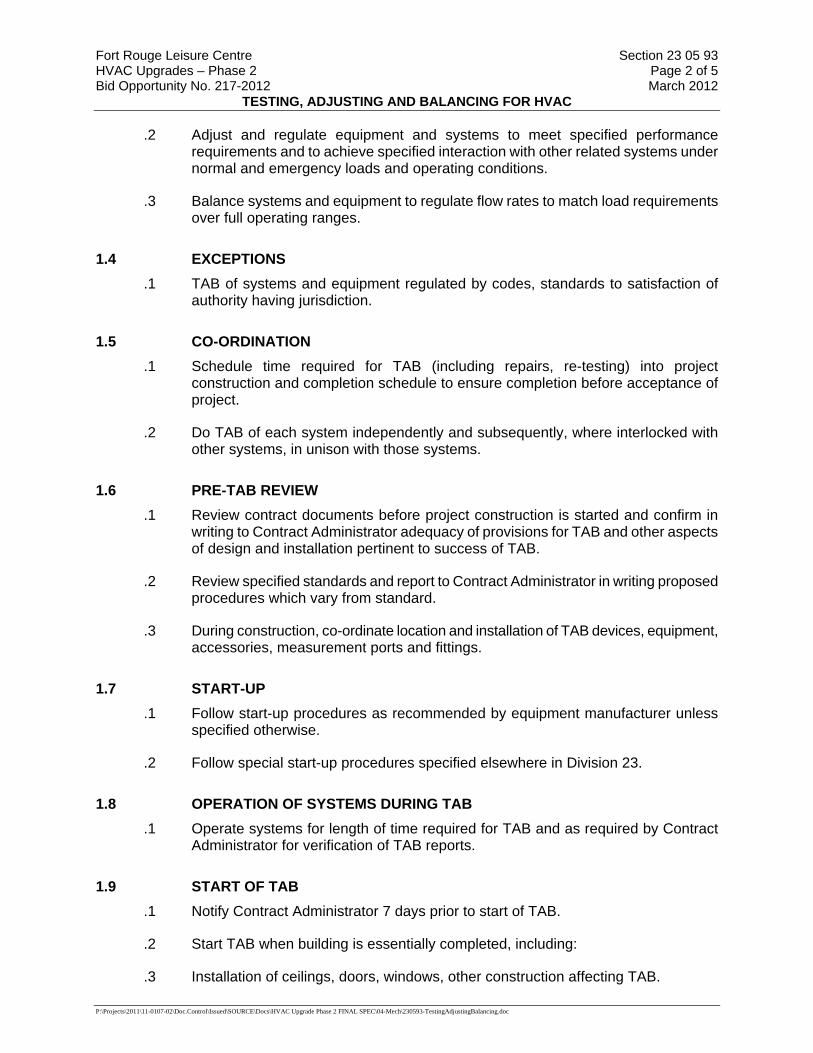
Fort Rouge Leisure Centre Section 23 05 93 HVAC Upgrades – Phase 2 Page 2 of 5 Bid Opportunity No. 217-2012 March 2012
TESTING, ADJUSTING AND BALANCING FOR HVAC
P:\Projects\2011\11-0107-02\Doc.Control\Issued\SOURCE\Docs\HVAC Upgrade Phase 2 FINAL SPEC\04-Mech\230593-TestingAdjustingBalancing.doc
.2 Adjust and regulate equipment and systems to meet specified performance requirements and to achieve specified interaction with other related systems under normal and emergency loads and operating conditions.
.3 Balance systems and equipment to regulate flow rates to match load requirements over full operating ranges.
1.4 EXCEPTIONS .1 TAB of systems and equipment regulated by codes, standards to satisfaction of
authority having jurisdiction.
1.5 CO-ORDINATION .1 Schedule time required for TAB (including repairs, re-testing) into project
construction and completion schedule to ensure completion before acceptance of project.
.2 Do TAB of each system independently and subsequently, where interlocked with other systems, in unison with those systems.
1.6 PRE-TAB REVIEW .1 Review contract documents before project construction is started and confirm in
writing to Contract Administrator adequacy of provisions for TAB and other aspects of design and installation pertinent to success of TAB.
.2 Review specified standards and report to Contract Administrator in writing proposed procedures which vary from standard.
.3 During construction, co-ordinate location and installation of TAB devices, equipment, accessories, measurement ports and fittings.
1.7 START-UP .1 Follow start-up procedures as recommended by equipment manufacturer unless
specified otherwise.
.2 Follow special start-up procedures specified elsewhere in Division 23.
1.8 OPERATION OF SYSTEMS DURING TAB .1 Operate systems for length of time required for TAB and as required by Contract
Administrator for verification of TAB reports.
1.9 START OF TAB .1 Notify Contract Administrator 7 days prior to start of TAB.
.2 Start TAB when building is essentially completed, including:
.3 Installation of ceilings, doors, windows, other construction affecting TAB.
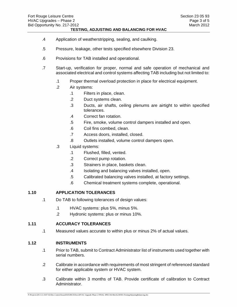
Fort Rouge Leisure Centre Section 23 05 93 HVAC Upgrades – Phase 2 Page 3 of 5 Bid Opportunity No. 217-2012 March 2012
TESTING, ADJUSTING AND BALANCING FOR HVAC
P:\Projects\2011\11-0107-02\Doc.Control\Issued\SOURCE\Docs\HVAC Upgrade Phase 2 FINAL SPEC\04-Mech\230593-TestingAdjustingBalancing.doc
.4 Application of weatherstripping, sealing, and caulking.
.5 Pressure, leakage, other tests specified elsewhere Division 23.
.6 Provisions for TAB installed and operational.
.7 Start-up, verification for proper, normal and safe operation of mechanical and associated electrical and control systems affecting TAB including but not limited to:
.1 Proper thermal overload protection in place for electrical equipment.
.2 Air systems: .1 Filters in place, clean. .2 Duct systems clean. .3 Ducts, air shafts, ceiling plenums are airtight to within specified
tolerances. .4 Correct fan rotation. .5 Fire, smoke, volume control dampers installed and open. .6 Coil fins combed, clean. .7 Access doors, installed, closed. .8 Outlets installed, volume control dampers open.
.3 Liquid systems: .1 Flushed, filled, vented. .2 Correct pump rotation. .3 Strainers in place, baskets clean. .4 Isolating and balancing valves installed, open. .5 Calibrated balancing valves installed, at factory settings. .6 Chemical treatment systems complete, operational.
1.10 APPLICATION TOLERANCES .1 Do TAB to following tolerances of design values:
.1 HVAC systems: plus 5%, minus 5%.
.2 Hydronic systems: plus or minus 10%.
1.11 ACCURACY TOLERANCES .1 Measured values accurate to within plus or minus 2% of actual values.
1.12 INSTRUMENTS .1 Prior to TAB, submit to Contract Administrator list of instruments used together with
serial numbers.
.2 Calibrate in accordance with requirements of most stringent of referenced standard for either applicable system or HVAC system.
.3 Calibrate within 3 months of TAB. Provide certificate of calibration to Contract Administrator.
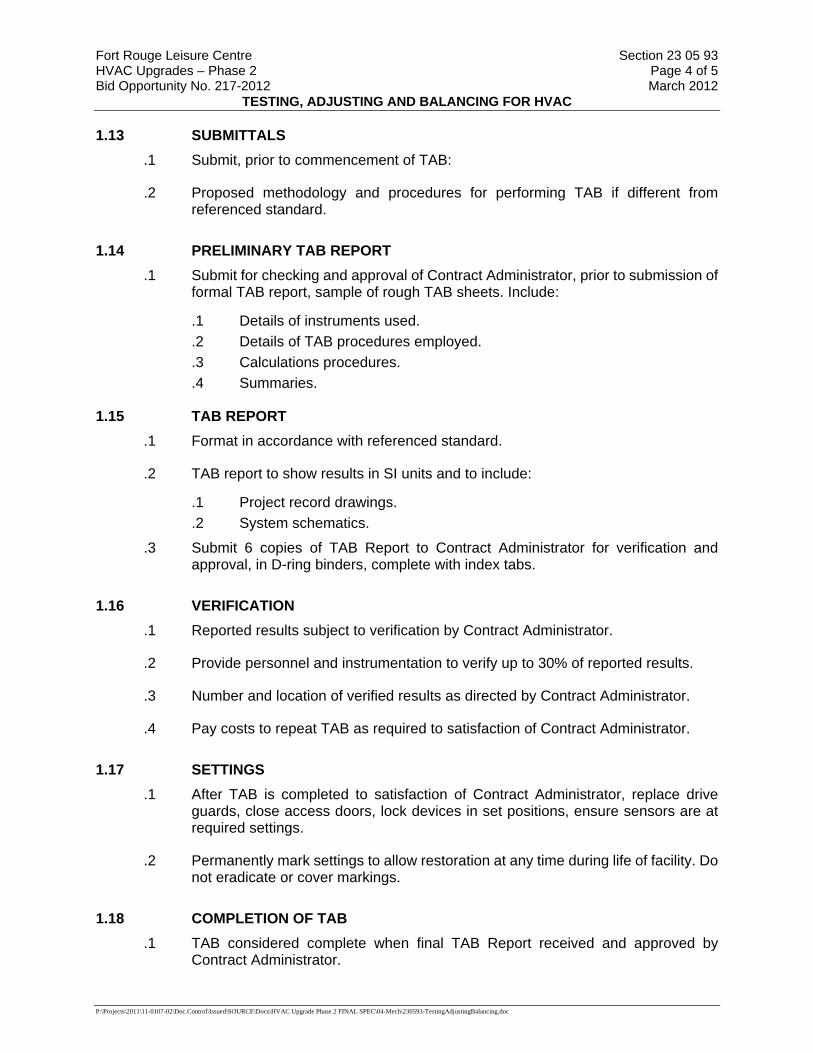
Fort Rouge Leisure Centre Section 23 05 93 HVAC Upgrades – Phase 2 Page 4 of 5 Bid Opportunity No. 217-2012 March 2012
TESTING, ADJUSTING AND BALANCING FOR HVAC
P:\Projects\2011\11-0107-02\Doc.Control\Issued\SOURCE\Docs\HVAC Upgrade Phase 2 FINAL SPEC\04-Mech\230593-TestingAdjustingBalancing.doc
1.13 SUBMITTALS .1 Submit, prior to commencement of TAB:
.2 Proposed methodology and procedures for performing TAB if different from referenced standard.
1.14 PRELIMINARY TAB REPORT .1 Submit for checking and approval of Contract Administrator, prior to submission of
formal TAB report, sample of rough TAB sheets. Include:
.1 Details of instruments used.
.2 Details of TAB procedures employed.
.3 Calculations procedures.
.4 Summaries.
1.15 TAB REPORT .1 Format in accordance with referenced standard.
.2 TAB report to show results in SI units and to include:
.1 Project record drawings.
.2 System schematics.
.3 Submit 6 copies of TAB Report to Contract Administrator for verification and approval, in D-ring binders, complete with index tabs.
1.16 VERIFICATION .1 Reported results subject to verification by Contract Administrator.
.2 Provide personnel and instrumentation to verify up to 30% of reported results.
.3 Number and location of verified results as directed by Contract Administrator.
.4 Pay costs to repeat TAB as required to satisfaction of Contract Administrator.
1.17 SETTINGS .1 After TAB is completed to satisfaction of Contract Administrator, replace drive
guards, close access doors, lock devices in set positions, ensure sensors are at required settings.
.2 Permanently mark settings to allow restoration at any time during life of facility. Do not eradicate or cover markings.
1.18 COMPLETION OF TAB .1 TAB considered complete when final TAB Report received and approved by
Contract Administrator.

Fort Rouge Leisure Centre Section 23 05 93 HVAC Upgrades – Phase 2 Page 5 of 5 Bid Opportunity No. 217-2012 March 2012
TESTING, ADJUSTING AND BALANCING FOR HVAC
P:\Projects\2011\11-0107-02\Doc.Control\Issued\SOURCE\Docs\HVAC Upgrade Phase 2 FINAL SPEC\04-Mech\230593-TestingAdjustingBalancing.doc
1.19 AIR SYSTEMS .1 Standard: TAB to most stringent of this section or TAB standards of AABC.
.1 Do TAB of systems, equipment, components, controls specified Division 23.
.2 Qualifications: personnel performing TAB current member in good standing of AABC.
.3 Quality assurance: perform TAB under direction of supervisor qualified by AABC.
.4 Measurements: to include as appropriate for systems, equipment, components, controls: air velocity, static pressure, flow rate, pressure drop (or loss), temperatures (dry bulb, wet bulb, dewpoint), duct cross-sectional area, RPM, electrical power, voltage, noise, vibration.
.5 Locations of equipment measurements: to include as appropriate:
.1 Inlet and outlet of dampers, filter, coil, humidifier, fan, other equipment causing changes in conditions.
.2 At controllers, controlled device.
.6 Locations of systems measurements to include as appropriate: main ducts, main branch, sub-branch, run-out (or grille, register or diffuser).
1.20 WATER SYSTEMS .1 Do TAB on all hydronic systems, equipment, components and controls specified in
Division 23 including flows to existing air handling units AHU-1 and AHU-2:
.2 Set water flows as noted. Obtain pump operating pressures, motor amperages and characteristics.
Part 2 Products
2.1 NOT USED .1 Not used.
Part 3 Execution
3.1 NOT USED .1 Not used.
END OF SECTION
Fort Rouge Leisure Centre Section 23 07 12 HVAC Upgrades – Phase 2 Page 1 of 3 Bid Opportunity No. 217-2012 March 2012
THERMAL INSULATION FOR PIPING
P:\Projects\2011\11-0107-02\Doc.Control\Issued\SOURCE\Docs\HVAC Upgrade Phase 2 FINAL SPEC\04-Mech\230712-Pipe Insulation.doc
Part 1 General
1.1 SUMMARY .1 Section Includes:
.1 Insulation of the following piping: .1 New hydronic piping .2 New refrigerant piping
1.2 REFERENCES .1 CAN/CGSB-51.9-92, Mineral Fibre Thermal Insulation for Piping and Round Ducting
.2 CGSB 51-GP-52Ma-89, Vapour Barrier Jacket and Facing Material for Pipe, Duct and Equipment Thermal Insulation.
1.3 SUBMITTALS .1 Product Data:
.1 Submit manufacturer's printed product literature, specifications and datasheet in accordance with Section 01 33 00 - Submittal Procedures. Include product characteristics, performance criteria, and limitations.
1.4 DEFINITIONS: .1 For purposes of this section:
.1 "CONCEALED" - insulated mechanical services and equipment in suspended ceilings and non-accessible chases and furred-in spaces.
.2 "EXPOSED" - will mean "not concealed" as defined herein.
.3 Insulation systems - insulation material, fasteners, jackets, etc.
Part 2 Products
2.1 GENERAL .1 Components of insulation system to have maximum flame spread rating of 25 and
maximum smoke developed rating of 50 in accordance with CAN/ULC-S102.
.2 Materials to be tested in accordance with ASTM C411.
2.2 P-1 FORMED MINERAL FIBER TO 200°C .1 Applications: new glycol piping.
.2 Materials:
.1 Rigid, one piece fibreglass pipe insulation with all service jacket of high density white kraft bonded to aluminum foil. Provide all weather protective jacket for outdoor installation.
.2 Acceptable materials: Schuller, Micro-lok, Knauf.
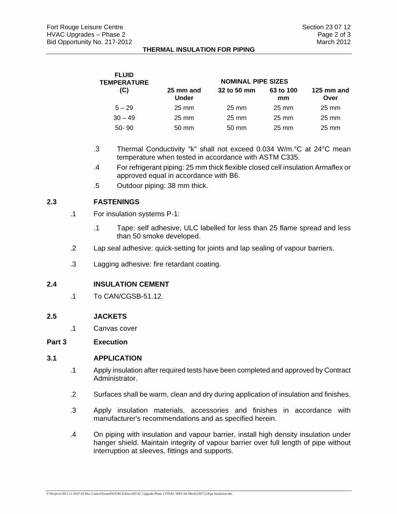
Fort Rouge Leisure Centre Section 23 07 12 HVAC Upgrades – Phase 2 Page 2 of 3 Bid Opportunity No. 217-2012 March 2012
THERMAL INSULATION FOR PIPING
P:\Projects\2011\11-0107-02\Doc.Control\Issued\SOURCE\Docs\HVAC Upgrade Phase 2 FINAL SPEC\04-Mech\230712-Pipe Insulation.doc
NOMINAL PIPE SIZES FLUID
TEMPERATURE (C) 25 mm and
Under 32 to 50 mm 63 to 100
mm 125 mm and
Over 5 – 29 25 mm 25 mm 25 mm 25 mm 30 – 49 25 mm 25 mm 25 mm 25 mm 50- 90 50 mm 50 mm 25 mm 25 mm
.3 Thermal Conductivity "k" shall not exceed 0.034 W/m.°C at 24°C mean
temperature when tested in accordance with ASTM C335. .4 For refrigerant piping: 25 mm thick flexible closed cell insulation Armaflex or
approved equal in accordance with B6. .5 Outdoor piping: 38 mm thick.
2.3 FASTENINGS .1 For insulation systems P-1:
.1 Tape: self adhesive, ULC labelled for less than 25 flame spread and less than 50 smoke developed.
.2 Lap seal adhesive: quick-setting for joints and lap sealing of vapour barriers.
.3 Lagging adhesive: fire retardant coating.
2.4 INSULATION CEMENT .1 To CAN/CGSB-51.12.
2.5 JACKETS .1 Canvas cover
Part 3 Execution
3.1 APPLICATION .1 Apply insulation after required tests have been completed and approved by Contract
Administrator.
.2 Surfaces shall be warm, clean and dry during application of insulation and finishes.
.3 Apply insulation materials, accessories and finishes in accordance with manufacturer's recommendations and as specified herein.
.4 On piping with insulation and vapour barrier, install high density insulation under hanger shield. Maintain integrity of vapour barrier over full length of pipe without interruption at sleeves, fittings and supports.
Fort Rouge Leisure Centre Section 23 07 12 HVAC Upgrades – Phase 2 Page 3 of 3 Bid Opportunity No. 217-2012 March 2012
THERMAL INSULATION FOR PIPING
P:\Projects\2011\11-0107-02\Doc.Control\Issued\SOURCE\Docs\HVAC Upgrade Phase 2 FINAL SPEC\04-Mech\230712-Pipe Insulation.doc
3.2 INSTALLATION .1 Install in accordance with ANSI/NFPA 90A and ANSI/NFPA 90B.
.2 Seal and finish exposed ends and other terminations with insulating cement.
.3 Flanges and unions at equipment, valves, other components requiring regular maintenance: omit insulation and bevel away from studs and nuts to permit use of tools without damage to insulation.
3.3 FASTENINGS .1 Secure pipe insulation by tape at each end and centre of each section, but not
greater than 900 mm on centres.
END OF SECTION
Fort Rouge Leisure Centre Section 23 07 13 HVAC Upgrades – Phase 2 Page 1 of 4 Bid Opportunity No. 217-2012 March 2012
THERMAL INSULATION FOR DUCTING
P:\Projects\2011\11-0107-02\Doc.Control\Issued\SOURCE\Docs\HVAC Upgrade Phase 2 FINAL SPEC\04-Mech\230713-DuctInsulation.doc
Part 1 General
1.1 REFERENCES .1 American Society of Heating, Refrigeration and Air Conditioning Engineers
(ASHRAE)
.1 ANSI/ASHRAE/IESNA 90.1-01, SI; Energy Standard for Buildings Except Low-Rise Residential Buildings.
.2 American Society for Testing and Materials International, (ASTM)
.1 ASTM B209M-02, Specification for Aluminum and Aluminum Alloy Sheet and Plate (Metric).
.2 ASTM C335-95, Test Method for Steady State Heat Transfer Properties of Horizontal Pipe Insulation.
.3 ASTM C411-97, Test Method for Hot-Surface Performance of High-Temperature Thermal Insulation.
.4 ASTM C449/C449M-00, Standard Specification for Mineral Fiber-Hydraulic-Setting Thermal Insulating and Finishing Cement.
.5 ASTM C547-00, Specification for Mineral Fiber Pipe Insulation.
.6 ASTM C553-00, Specification for Mineral Fiber Blanket Thermal Insulation for Commercial and Industrial Applications.
.7 ASTM C612-00a, Specification for Mineral Fiber Block and Board Thermal Insulation.
.8 ASTM C795-92, Specification for Thermal Insulation for Use with Austenitic Stainless Steel.
.9 ASTM C921-92(1998)e1, Standard Specification for Thermal Insulation for Use in Contact with Austenitic Stainless Steel.
.3 Canadian General Standards Board (CGSB)
.1 CGSB 51-GP-52Ma-89, Vapour Barrier, Jacket and Facing Material for Pipe, Duct and Equipment Thermal Insulation.
.4 Thermal Insulation Association of Canada (TIAC): National Insulation Standards (R1999).
.5 Underwriters Laboratories of Canada (ULC)
.1 CAN/ULC-S102-M88(R2000), Surface Burning Characteristics of Building Materials and Assemblies.
.2 CAN/ULC-S701-01, Thermal Insulation Polyotrene, Boards and Pipe Covering.
1.2 DEFINITIONS .1 For purposes of this section:
.1 "CONCEALED" - insulated mechanical services and equipment in suspended ceilings and non-accessible chases and furred-in spaces.
.2 "EXPOSED" - will mean "not concealed" as defined herein.
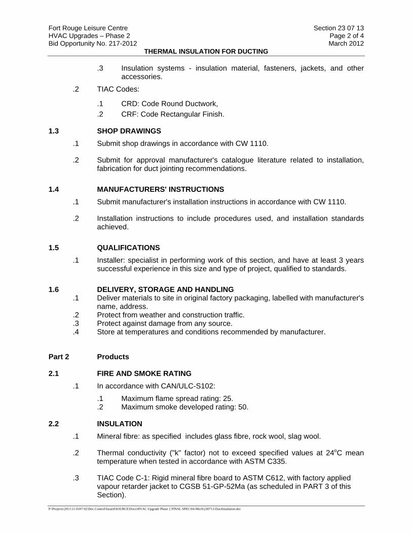
Fort Rouge Leisure Centre Section 23 07 13 HVAC Upgrades – Phase 2 Page 2 of 4 Bid Opportunity No. 217-2012 March 2012
THERMAL INSULATION FOR DUCTING
P:\Projects\2011\11-0107-02\Doc.Control\Issued\SOURCE\Docs\HVAC Upgrade Phase 2 FINAL SPEC\04-Mech\230713-DuctInsulation.doc
.3 Insulation systems - insulation material, fasteners, jackets, and other accessories.
.2 TIAC Codes:
.1 CRD: Code Round Ductwork,
.2 CRF: Code Rectangular Finish.
1.3 SHOP DRAWINGS .1 Submit shop drawings in accordance with CW 1110.
.2 Submit for approval manufacturer's catalogue literature related to installation, fabrication for duct jointing recommendations.
1.4 MANUFACTURERS' INSTRUCTIONS .1 Submit manufacturer's installation instructions in accordance with CW 1110.
.2 Installation instructions to include procedures used, and installation standards achieved.
1.5 QUALIFICATIONS .1 Installer: specialist in performing work of this section, and have at least 3 years
successful experience in this size and type of project, qualified to standards.
1.6 DELIVERY, STORAGE AND HANDLING .1 Deliver materials to site in original factory packaging, labelled with manufacturer's
name, address. .2 Protect from weather and construction traffic. .3 Protect against damage from any source. .4 Store at temperatures and conditions recommended by manufacturer.
Part 2 Products
2.1 FIRE AND SMOKE RATING .1 In accordance with CAN/ULC-S102:
.1 Maximum flame spread rating: 25.
.2 Maximum smoke developed rating: 50.
2.2 INSULATION .1 Mineral fibre: as specified includes glass fibre, rock wool, slag wool.
.2 Thermal conductivity ("k" factor) not to exceed specified values at 24oC mean temperature when tested in accordance with ASTM C335.
.3 TIAC Code C-1: Rigid mineral fibre board to ASTM C612, with factory applied vapour retarder jacket to CGSB 51-GP-52Ma (as scheduled in PART 3 of this Section).
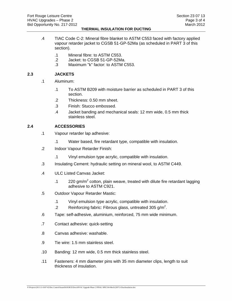
Fort Rouge Leisure Centre Section 23 07 13 HVAC Upgrades – Phase 2 Page 3 of 4 Bid Opportunity No. 217-2012 March 2012
THERMAL INSULATION FOR DUCTING
P:\Projects\2011\11-0107-02\Doc.Control\Issued\SOURCE\Docs\HVAC Upgrade Phase 2 FINAL SPEC\04-Mech\230713-DuctInsulation.doc
.4 TIAC Code C-2: Mineral fibre blanket to ASTM C553 faced with factory applied vapour retarder jacket to CGSB 51-GP-52Ma (as scheduled in PART 3 of this section).
.1 Mineral fibre: to ASTM C553.
.2 Jacket: to CGSB 51-GP-52Ma.
.3 Maximum "k" factor: to ASTM C553.
2.3 JACKETS .1 Aluminum:
.1 To ASTM B209 with moisture barrier as scheduled in PART 3 of this section.
.2 Thickness: 0.50 mm sheet.
.3 Finish: Stucco embossed.
.4 Jacket banding and mechanical seals: 12 mm wide, 0.5 mm thick stainless steel.
2.4 ACCESSORIES .1 Vapour retarder lap adhesive:
.1 Water based, fire retardant type, compatible with insulation.
.2 Indoor Vapour Retarder Finish:
.1 Vinyl emulsion type acrylic, compatible with insulation.
.3 Insulating Cement: hydraulic setting on mineral wool, to ASTM C449.
.4 ULC Listed Canvas Jacket:
.1 220 gm/m2 cotton, plain weave, treated with dilute fire retardant lagging adhesive to ASTM C921.
.5 Outdoor Vapour Retarder Mastic:
.1 Vinyl emulsion type acrylic, compatible with insulation.
.2 Reinforcing fabric: Fibrous glass, untreated 305 g/m2.
.6 Tape: self-adhesive, aluminium, reinforced, 75 mm wide minimum.
.7 Contact adhesive: quick-setting
.8 Canvas adhesive: washable.
.9 Tie wire: 1.5 mm stainless steel.
.10 Banding: 12 mm wide, 0.5 mm thick stainless steel.
.11 Fasteners: 4 mm diameter pins with 35 mm diameter clips, length to suit thickness of insulation.
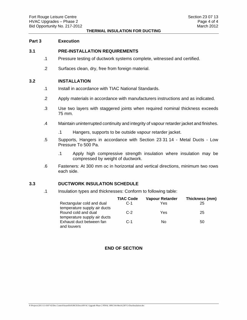
Fort Rouge Leisure Centre Section 23 07 13 HVAC Upgrades – Phase 2 Page 4 of 4 Bid Opportunity No. 217-2012 March 2012
THERMAL INSULATION FOR DUCTING
P:\Projects\2011\11-0107-02\Doc.Control\Issued\SOURCE\Docs\HVAC Upgrade Phase 2 FINAL SPEC\04-Mech\230713-DuctInsulation.doc
Part 3 Execution
3.1 PRE-INSTALLATION REQUIREMENTS .1 Pressure testing of ductwork systems complete, witnessed and certified.
.2 Surfaces clean, dry, free from foreign material.
3.2 INSTALLATION .1 Install in accordance with TIAC National Standards.
.2 Apply materials in accordance with manufacturers instructions and as indicated.
.3 Use two layers with staggered joints when required nominal thickness exceeds 75 mm.
.4 Maintain uninterrupted continuity and integrity of vapour retarder jacket and finishes.
.1 Hangers, supports to be outside vapour retarder jacket.
.5 Supports, Hangers in accordance with Section 23 31 14 - Metal Ducts - Low Pressure To 500 Pa.
.1 Apply high compressive strength insulation where insulation may be compressed by weight of ductwork.
.6 Fasteners: At 300 mm oc in horizontal and vertical directions, minimum two rows each side.
3.3 DUCTWORK INSULATION SCHEDULE .1 Insulation types and thicknesses: Conform to following table:
TIAC Code Vapour Retarder Thickness (mm) Rectangular cold and dual temperature supply air ducts
C-1 Yes 25
Round cold and dual temperature supply air ducts
C-2 Yes 25
Exhaust duct between fan and louvers
C-1 No 50
END OF SECTION

Fort Rouge Leisure Centre Section 23 09 33 HVAC System Upgrade Page 1 of 15 Bid Opportunity No. 217-2012 March 2012
CONTROL SYSTEM FOR HVAC
P:\Projects\2011\11-0107-02\Doc.Control\Issued\SOURCE\Docs\HVAC Upgrade Phase 2 FINAL SPEC\04-Mech\230933-DDC.doc
Part 1 General
1.1 General and Related Work .1 All work of this Division shall be coordinated and provided by the single
Building Management System (BMS) Contractor. .2 If the Contractor believes there are conflicts or missing information in the
Contract Documents then the Contractor shall promptly request clarification and instruction from the Contract Administrator before proceeding.
.3 No LON protocols are accepted.
.4 The Contractor to supply all drawings/graphics/sequence of operations in both a hard and soft copy. Drawings and graphics to be able to be read and modified by City of Winnipeg Staff using Microsoft Visio software.
.5 The Contractor to provide commissioning sheets for all points on field devices as well as head end equipment.
.6 The Contractor shall meet with City of Winnipeg Tech Shop staff to go over naming conventions, graphics, alarms etc. at the start of project. Controller addresses to be coordinated with the Tech Shop.
.7 The work of this Division shall be scheduled, coordinated, and interfaced with the associated work of other trades. Reference the Mechanical Division Sections for details.
.8 The Contractor shall have visited the Project site and obtained information as necessary prior to submittal of the bid to ensure that prevailing physical conditions and Project arrangements that may be material to the performance of the Work have been ascertained and accommodated in the bid. No claims for additional payments will be accepted due to the Contractor’s failure to complete this survey.
.9 If, in order to complete the Work of the Controls Contract, private and/or public telephone lines and connections, including ISDN lines and/or LAN/WAN support and connections, are required then these shall be provided by the City to the Contractor, at the City's direct cost, in a timely manner.
.10 There is an existing central monitoring system in place. The Contractor shall visit the City of Winnipeg tech shop for a walk through of the existing controls prior to bid closing date. Where DDC points are identified as centrally monitored points, the Contractor shall provide and install required hardware and software to interface to the existing Johnson Controls Metasys EA servers and workstations. These are located at the Central Control Offices, 510 Main Street, Winnipeg, Manitoba.
.11 This facility has existing Johnson Controls DDC systems using N2 open communication bus technology. Controls contractor to supply all drawings/graphics/sequence of operations in both a hard and soft copy. Drawings and graphics to be able to be read and modified by City of Winnipeg Staff using Microsoft Visio software.
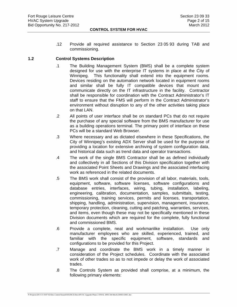
Fort Rouge Leisure Centre Section 23 09 33 HVAC System Upgrade Page 2 of 15 Bid Opportunity No. 217-2012 March 2012
CONTROL SYSTEM FOR HVAC
P:\Projects\2011\11-0107-02\Doc.Control\Issued\SOURCE\Docs\HVAC Upgrade Phase 2 FINAL SPEC\04-Mech\230933-DDC.doc
.12 Provide all required assistance to Section 23 05 93 during TAB and commissioning.
1.2 Control Systems Description .1 The Building Management System (BMS) shall be a complete system
designed for use with the enterprise IT systems in place at the City of Winnipeg. This functionality shall extend into the equipment rooms. Devices residing on the automation network located in equipment rooms and similar shall be fully IT compatible devices that mount and communicate directly on the IT infrastructure in the facility. Contractor shall be responsible for coordination with the Contract Administrator’s IT staff to ensure that the FMS will perform in the Contract Administrator’s environment without disruption to any of the other activities taking place on that LAN.
.2 All points of user interface shall be on standard PCs that do not require the purchase of any special software from the BMS manufacturer for use as a building operations terminal. The primary point of interface on these PCs will be a standard Web Browser.
.3 Where necessary and as dictated elsewhere in these Specifications, the City of Winnipeg’s existing ADX Server shall be used for the purpose of providing a location for extensive archiving of system configuration data, and historical data such as trend data and operator transactions.
.4 The work of the single BMS Contractor shall be as defined individually and collectively in all Sections of this Division specification together with the associated Point Sheets and Drawings and the associated interfacing work as referenced in the related documents.
.5 The BMS work shall consist of the provision of all labor, materials, tools, equipment, software, software licenses, software configurations and database entries, interfaces, wiring, tubing, installation, labeling, engineering, calibration, documentation, samples, submittals, testing, commissioning, training services, permits and licenses, transportation, shipping, handling, administration, supervision, management, insurance, temporary protection, cleaning, cutting and patching, warranties, services, and items, even though these may not be specifically mentioned in these Division documents which are required for the complete, fully functional and commissioned BMS.
.6 Provide a complete, neat and workmanlike installation. Use only manufacturer employees who are skilled, experienced, trained, and familiar with the specific equipment, software, standards and configurations to be provided for this Project.
.7 Manage and coordinate the BMS work in a timely manner in consideration of the Project schedules. Coordinate with the associated work of other trades so as to not impede or delay the work of associated trades.
.8 The Controls System as provided shall comprise, at a minimum, the following primary elements:

Fort Rouge Leisure Centre Section 23 09 33 HVAC System Upgrade Page 3 of 15 Bid Opportunity No. 217-2012 March 2012
CONTROL SYSTEM FOR HVAC
P:\Projects\2011\11-0107-02\Doc.Control\Issued\SOURCE\Docs\HVAC Upgrade Phase 2 FINAL SPEC\04-Mech\230933-DDC.doc
.1 Network and application nodes.
.2 Field devices.
.3 Control wiring. .2 Submittals
.1 Shop Drawings, Product Data, and Samples .1 The BMS contractor shall submit a list of all shop drawings with
submittals dates within 30 days of contract award. .2 Submittals shall be in defined packages. Each package shall be
complete and shall only reference itself and previously submitted packages. The packages shall be as approved by the Contract Administrator for Contract compliance.
.3 Allow 15 working days for the review of each package by the Contract Administrator in the scheduling of the total BMS work.
.4 Equipment and systems requiring approval of local authorities must comply with such regulations and be approved. Filing shall be at the expense of the BMS Contractor where filing is necessary. Provide a copy of all related correspondence and permits to the Contract Administrator.
.5 Prepare an index of all submittals and shop drawings for the installation. Index shall include a shop drawing identification number, Contract Documents reference and item description.
.6 The BMS Contractor shall correct any errors or omissions noted in the first review.
.7 At a minimum, submit the following: .1 BMS network architecture diagrams including all nodes
and interconnections. .2 Systems schematics, sequences and flow diagrams. .3 Points schedule for each point in the BMS, including: Point
Type, Object Name, Expanded ID, Display Units, Controller type, and Address.
.4 Samples of Graphic Display screen types and associated menus.
.5 Detailed Bill of Material list for each system Part 2 Products
2.1 N2 DDC System Controllers.
.1 Digital Controller w/ eXtension capability (DX) .1 Each DX shall operate as a standalone controller capable of performing
its specified control responsibilities independently of other controllers in the network. Each DCX shall be a microprocessor-Based, multi-tasking, real-time digital control processor.
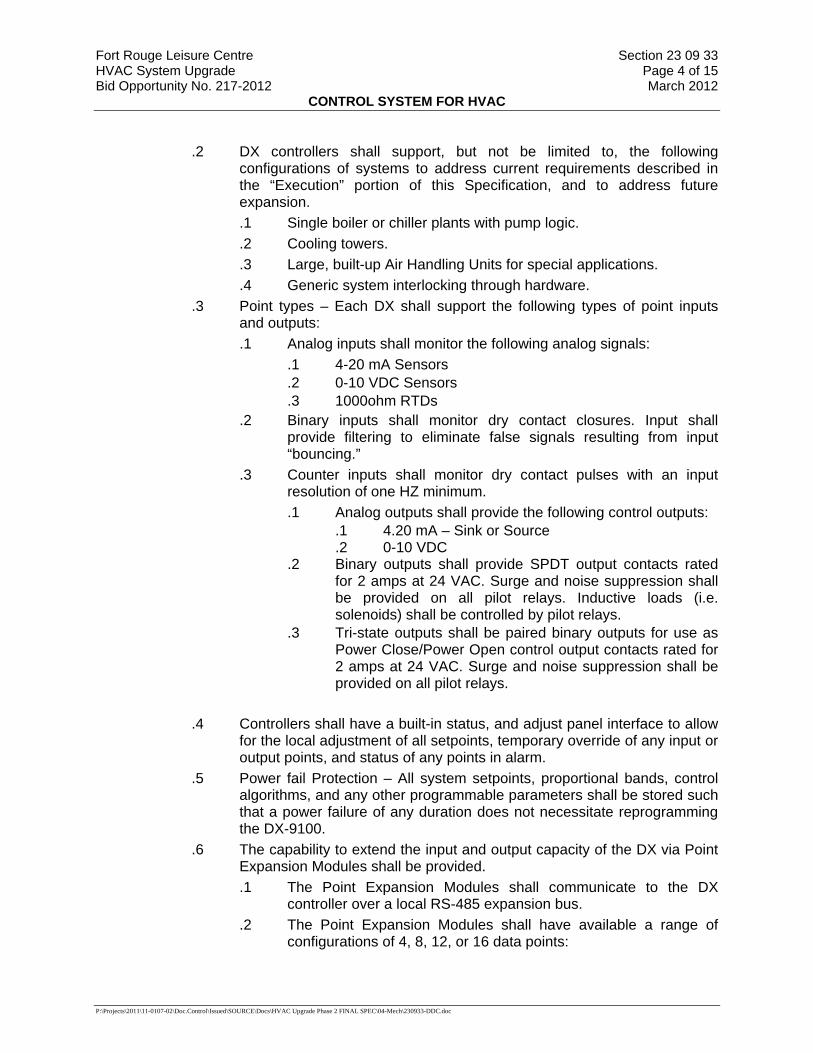
Fort Rouge Leisure Centre Section 23 09 33 HVAC System Upgrade Page 4 of 15 Bid Opportunity No. 217-2012 March 2012
CONTROL SYSTEM FOR HVAC
P:\Projects\2011\11-0107-02\Doc.Control\Issued\SOURCE\Docs\HVAC Upgrade Phase 2 FINAL SPEC\04-Mech\230933-DDC.doc
.2 DX controllers shall support, but not be limited to, the following configurations of systems to address current requirements described in the “Execution” portion of this Specification, and to address future expansion. .1 Single boiler or chiller plants with pump logic. .2 Cooling towers. .3 Large, built-up Air Handling Units for special applications. .4 Generic system interlocking through hardware.
.3 Point types – Each DX shall support the following types of point inputs and outputs: .1 Analog inputs shall monitor the following analog signals:
.1 4-20 mA Sensors
.2 0-10 VDC Sensors
.3 1000ohm RTDs .2 Binary inputs shall monitor dry contact closures. Input shall
provide filtering to eliminate false signals resulting from input “bouncing.”
.3 Counter inputs shall monitor dry contact pulses with an input resolution of one HZ minimum. .1 Analog outputs shall provide the following control outputs:
.1 4.20 mA – Sink or Source
.2 0-10 VDC .2 Binary outputs shall provide SPDT output contacts rated
for 2 amps at 24 VAC. Surge and noise suppression shall be provided on all pilot relays. Inductive loads (i.e. solenoids) shall be controlled by pilot relays.
.3 Tri-state outputs shall be paired binary outputs for use as Power Close/Power Open control output contacts rated for 2 amps at 24 VAC. Surge and noise suppression shall be provided on all pilot relays.
.4 Controllers shall have a built-in status, and adjust panel interface to allow
for the local adjustment of all setpoints, temporary override of any input or output points, and status of any points in alarm.
.5 Power fail Protection – All system setpoints, proportional bands, control algorithms, and any other programmable parameters shall be stored such that a power failure of any duration does not necessitate reprogramming the DX-9100.
.6 The capability to extend the input and output capacity of the DX via Point Expansion Modules shall be provided. .1 The Point Expansion Modules shall communicate to the DX
controller over a local RS-485 expansion bus. .2 The Point Expansion Modules shall have available a range of
configurations of 4, 8, 12, or 16 data points:

Fort Rouge Leisure Centre Section 23 09 33 HVAC System Upgrade Page 5 of 15 Bid Opportunity No. 217-2012 March 2012
CONTROL SYSTEM FOR HVAC
P:\Projects\2011\11-0107-02\Doc.Control\Issued\SOURCE\Docs\HVAC Upgrade Phase 2 FINAL SPEC\04-Mech\230933-DDC.doc
.1 Analog Inputs – 0-10V, 4-20mA, 1000 ohm RTD
.2 Analog Outputs – 0-10V, 4-20mA
.3 Digital Inputs w/ digital counter
.4 Digital Outputs – triacs or relay contacts .3 Expansion module data points shall be available for inclusion in all
DX control strategies.
.2 Application Specific Controllers .1 Air Handling Unit Controllers (AHU)
.1 Each Air Handling Unit controller shall operate as a standalone controller capable of performing its specified control responsibilities independently of other controllers in the network. Each AHU controller shall be a microprocessor-Based, multi-tasking, real-time digital control processor
.2 AHU controllers shall support, but not be limited to, the following configurations of systems to address current requirements as described in the “Execution” portion of this Specification, and to address future expansion: .1 Air Handling Units:
.1 Mixed Air-Single Path
.2 Mixed Air-Dual Path
.3 100% Single Path
.4 100% Dual Path .3 Each AHU controller shall have sufficient memory to support its
own operating system and databases, including: .1 Control Processes .2 Energy Management Applications .3 Operator I/O (Portable Service Terminal)
.4 Point types – Each AHU controller shall support the following types of point inputs and outputs: .1 Analog inputs shall monitor the following analog signals:
.1 4-20 mA Sensors
.2 0-10 VDC Sensors
.3 1000ohm RTDs .2 Binary inputs shall monitor dry contact closures. Input shall
provide filtering to eliminate false signals resulting from input “bouncing.”
.3 Counter inputs shall monitor dry contact pulses with an input resolution of one HZ minimum.
.4 Analog outputs shall provide the following control outputs: .1 4.20 mA – Sink or Source .2 0-10 VDC
.5 Binary outputs shall provide SPDT output contacts rated for 2 amps at 24 VAC. Surge and noise suppression shall

Fort Rouge Leisure Centre Section 23 09 33 HVAC System Upgrade Page 6 of 15 Bid Opportunity No. 217-2012 March 2012
CONTROL SYSTEM FOR HVAC
P:\Projects\2011\11-0107-02\Doc.Control\Issued\SOURCE\Docs\HVAC Upgrade Phase 2 FINAL SPEC\04-Mech\230933-DDC.doc
be provided on all pilot relays. Inductive loads (i.e. solenoids) shall be controlled by pilot relays.
.6 Tri-state outputs shall be paired binary outputs for use as Power Close/Power Open control output contacts rated for 2 amps at 24 VAC. Surge and noise suppression shall be provided on all pilot relays.
.5 AHU controllers shall have a library of control routines and
program logic to perform the sequence of operations specified in the “Execution” portion of this Specification.
.6 AHU controllers shall directly support the temporary use of a portable service terminal that can be connected to the AHU via zone temperature or directly at the controller.
.7 Power fail Protection – All system setpoints, proportional bands, control algorithms, and any other programmable parameters shall be stored such that a power failure of any duration does not necessitate reprogramming the AHU.
.2 Unitary Controllers (UNT) .1 Each Unitary Controller shall operate as a standalone controller
capable of performing its specified control responsibilities independently of other controllers in the network. Each Unitary Controller shall be a microprocessor-Based, multi-tasking, real-time digital control processor.
.2 Unitary Controllers shall support, but not be limited to, the following types of systems to address specific applications described in the “Execution” portion of this Specification, and to address future expansion: .1 Unit Vents (ASHRAE Cycle, I, II, III, or W). .2 Heat Pumps (Air-to-Air, Water-to-Air). .3 Packaged Rooftops. .4 Fan Coils (Two-Pipe, Four-Pipe).
.3 Point types – Each Unitary Controller shall support the following types of point inputs and outputs: .1 Analog inputs shall monitor the following analog signals:
.1 0-10 VDC Sensors
.2 1000ohm RTDs .2 Binary inputs shall monitor dry contact closures. Input shall
provide filtering to eliminate false signals resulting from input “bouncing.”
.3 Counter inputs shall monitor dry contact pulses with an input resolution of one HZ minimum.
.4 Analog outputs shall provide the following control outputs: .1 0-10 VDC
.5 Binary outputs shall provide SPDT output contacts rated for 2 amps at 24 VAC. Surge and noise suppression shall
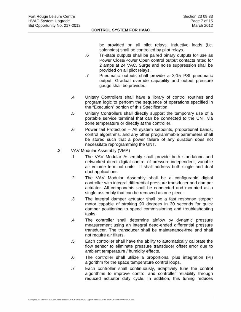
Fort Rouge Leisure Centre Section 23 09 33 HVAC System Upgrade Page 7 of 15 Bid Opportunity No. 217-2012 March 2012
CONTROL SYSTEM FOR HVAC
P:\Projects\2011\11-0107-02\Doc.Control\Issued\SOURCE\Docs\HVAC Upgrade Phase 2 FINAL SPEC\04-Mech\230933-DDC.doc
be provided on all pilot relays. Inductive loads (i.e. solenoids) shall be controlled by pilot relays.
.6 Tri-state outputs shall be paired binary outputs for use as Power Close/Power Open control output contacts rated for 2 amps at 24 VAC. Surge and noise suppression shall be provided on all pilot relays.
.7 Pneumatic outputs shall provide a 3-15 PSI pneumatic output. Gradual override capability and output pressure gauge shall be provided.
.4 Unitary Controllers shall have a library of control routines and
program logic to perform the sequence of operations specified in the “Execution” portion of this Specification.
.5 Unitary Controllers shall directly support the temporary use of a portable service terminal that can be connected to the UNT via zone temperature or directly at the controller.
.6 Power fail Protection – All system setpoints, proportional bands, control algorithms, and any other programmable parameters shall be stored such that a power failure of any duration does not necessitate reprogramming the UNT.
.3 VAV Modular Assembly (VMA) .1 The VAV Modular Assembly shall provide both standalone and
networked direct digital control of pressure-independent, variable air volume terminal units. It shall address both single and dual duct applications.
.2 The VAV Modular Assembly shall be a configurable digital controller with integral differential pressure transducer and damper actuator. All components shall be connected and mounted as a single assembly that can be removed as one piece.
.3 The integral damper actuator shall be a fast response stepper motor capable of stroking 90 degrees in 30 seconds for quick damper positioning to speed commissioning and troubleshooting tasks.
.4 The controller shall determine airflow by dynamic pressure measurement using an integral dead-ended differential pressure transducer. The transducer shall be maintenance-free and shall not require air filters.
.5 Each controller shall have the ability to automatically calibrate the flow sensor to eliminate pressure transducer offset error due to ambient temperature / humidity effects.
.6 The controller shall utilize a proportional plus integration (PI) algorithm for the space temperature control loops.
.7 Each controller shall continuously, adaptively tune the control algorithms to improve control and controller reliability through reduced actuator duty cycle. In addition, this tuning reduces
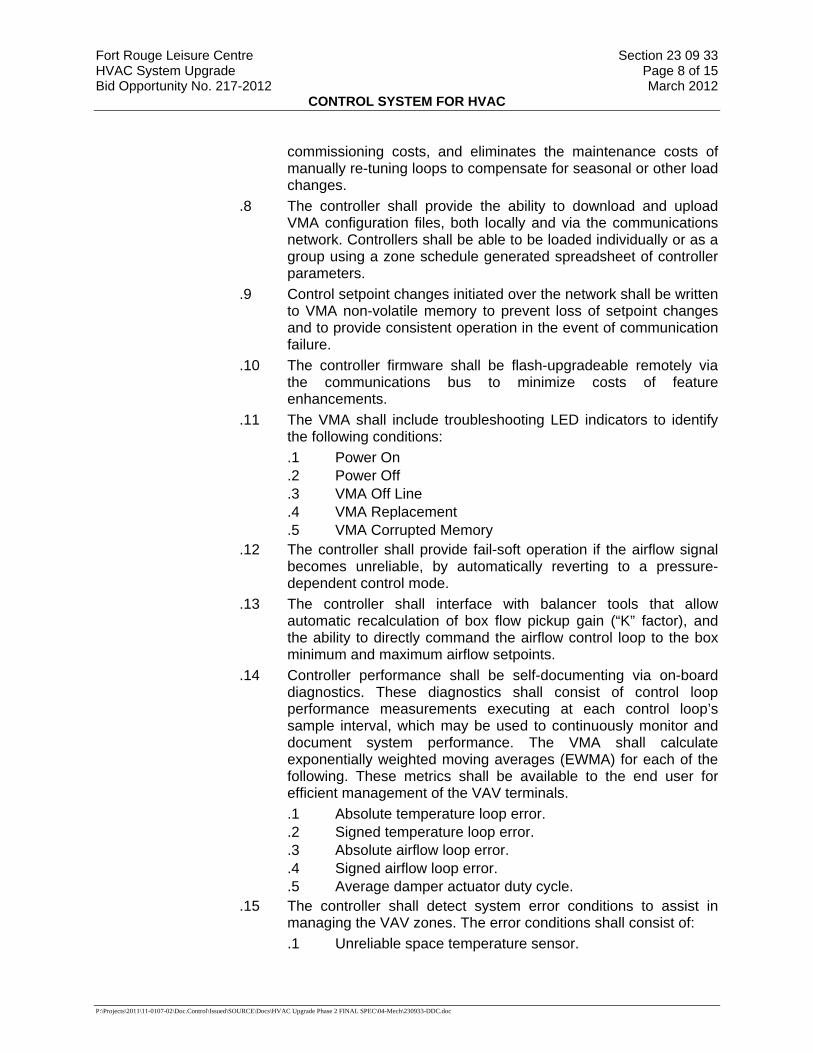
Fort Rouge Leisure Centre Section 23 09 33 HVAC System Upgrade Page 8 of 15 Bid Opportunity No. 217-2012 March 2012
CONTROL SYSTEM FOR HVAC
P:\Projects\2011\11-0107-02\Doc.Control\Issued\SOURCE\Docs\HVAC Upgrade Phase 2 FINAL SPEC\04-Mech\230933-DDC.doc
commissioning costs, and eliminates the maintenance costs of manually re-tuning loops to compensate for seasonal or other load changes.
.8 The controller shall provide the ability to download and upload VMA configuration files, both locally and via the communications network. Controllers shall be able to be loaded individually or as a group using a zone schedule generated spreadsheet of controller parameters.
.9 Control setpoint changes initiated over the network shall be written to VMA non-volatile memory to prevent loss of setpoint changes and to provide consistent operation in the event of communication failure.
.10 The controller firmware shall be flash-upgradeable remotely via the communications bus to minimize costs of feature enhancements.
.11 The VMA shall include troubleshooting LED indicators to identify the following conditions: .1 Power On .2 Power Off .3 VMA Off Line .4 VMA Replacement .5 VMA Corrupted Memory
.12 The controller shall provide fail-soft operation if the airflow signal becomes unreliable, by automatically reverting to a pressure-dependent control mode.
.13 The controller shall interface with balancer tools that allow automatic recalculation of box flow pickup gain (“K” factor), and the ability to directly command the airflow control loop to the box minimum and maximum airflow setpoints.
.14 Controller performance shall be self-documenting via on-board diagnostics. These diagnostics shall consist of control loop performance measurements executing at each control loop’s sample interval, which may be used to continuously monitor and document system performance. The VMA shall calculate exponentially weighted moving averages (EWMA) for each of the following. These metrics shall be available to the end user for efficient management of the VAV terminals. .1 Absolute temperature loop error. .2 Signed temperature loop error. .3 Absolute airflow loop error. .4 Signed airflow loop error. .5 Average damper actuator duty cycle.
.15 The controller shall detect system error conditions to assist in managing the VAV zones. The error conditions shall consist of: .1 Unreliable space temperature sensor.
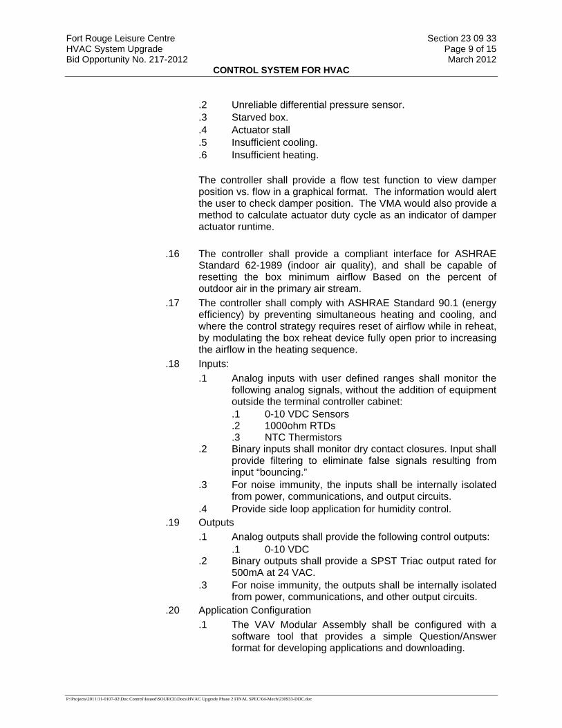
Fort Rouge Leisure Centre Section 23 09 33 HVAC System Upgrade Page 9 of 15 Bid Opportunity No. 217-2012 March 2012
CONTROL SYSTEM FOR HVAC
P:\Projects\2011\11-0107-02\Doc.Control\Issued\SOURCE\Docs\HVAC Upgrade Phase 2 FINAL SPEC\04-Mech\230933-DDC.doc
.2 Unreliable differential pressure sensor.
.3 Starved box.
.4 Actuator stall
.5 Insufficient cooling.
.6 Insufficient heating. The controller shall provide a flow test function to view damper position vs. flow in a graphical format. The information would alert the user to check damper position. The VMA would also provide a method to calculate actuator duty cycle as an indicator of damper actuator runtime.
.16 The controller shall provide a compliant interface for ASHRAE
Standard 62-1989 (indoor air quality), and shall be capable of resetting the box minimum airflow Based on the percent of outdoor air in the primary air stream.
.17 The controller shall comply with ASHRAE Standard 90.1 (energy efficiency) by preventing simultaneous heating and cooling, and where the control strategy requires reset of airflow while in reheat, by modulating the box reheat device fully open prior to increasing the airflow in the heating sequence.
.18 Inputs: .1 Analog inputs with user defined ranges shall monitor the
following analog signals, without the addition of equipment outside the terminal controller cabinet: .1 0-10 VDC Sensors .2 1000ohm RTDs .3 NTC Thermistors
.2 Binary inputs shall monitor dry contact closures. Input shall provide filtering to eliminate false signals resulting from input “bouncing.”
.3 For noise immunity, the inputs shall be internally isolated from power, communications, and output circuits.
.4 Provide side loop application for humidity control. .19 Outputs
.1 Analog outputs shall provide the following control outputs: .1 0-10 VDC
.2 Binary outputs shall provide a SPST Triac output rated for 500mA at 24 VAC.
.3 For noise immunity, the outputs shall be internally isolated from power, communications, and other output circuits.
.20 Application Configuration .1 The VAV Modular Assembly shall be configured with a
software tool that provides a simple Question/Answer format for developing applications and downloading.
Fort Rouge Leisure Centre Section 23 09 33 HVAC System Upgrade Page 10 of 15 Bid Opportunity No. 217-2012 March 2012
CONTROL SYSTEM FOR HVAC
P:\Projects\2011\11-0107-02\Doc.Control\Issued\SOURCE\Docs\HVAC Upgrade Phase 2 FINAL SPEC\04-Mech\230933-DDC.doc
.21 Sensor Support .1 The VMA shall support an LCD display room sensor. .2 The VMA shall also support standard room sensors as
defined by analog input requirements. .3 The VMA shall support humidity sensors defined by the AI
side loop. Part 3 Execution 3.1 Installation
.1 General
.1 The project plans shall be thoroughly examined for control device and equipment locations. Any discrepancies, conflicts, or omissions shall be reported to the Contract Administrator for resolution before rough-in work is started.
.2 The contractor shall inspect the site to verify that equipment may be installed as shown. Any discrepancies, conflicts, or omissions shall be reported to the Contract Administrator for resolution before rough-in work is started.
.3 The contractor shall examine the drawings and specifications for other parts of the work. If head room or space conditions appear inadequate or if any discrepancies occur between the plans and the contractor’s work and the plans and the work of others the contractor shall report these discrepancies to the Contract Administrator and shall obtain written instructions for any changes necessary to accommodate the contractor’s work with the work of others. Any changes in the work covered by this specification made necessary by the failure or neglect of the contractor to report such discrepancies shall be made by—and at the expense of—this contractor.
.4 All items shall be installed in accordance with manufacturer’s instructions. All conduit shall be independently supported from the structure in an approved manner.
.5 The control equipment and connecting conduit and wire shall be installed in a neat and workmanlike manner by personnel skilled in this type of installation. All tubing, conduit and plenum rated cable shall be run in an approved manner; conduit shall be run parallel to or at right angles to the building structure. All conduit, tubing, and plenum cable shall be concealed in all finished spaces. Conduit containing wire or non-metallic tubing may be installed exposed in mechanical rooms or areas where other piping is run exposed.
.6 Non-metallic tubing and plenum cable may be used in concealed accessible spaces provided such installation is allowed by local codes.
.7 All electrical work shall be installed by experienced personnel and conform to CEC and all local codes. Where requirements of Division 26
Fort Rouge Leisure Centre Section 23 09 33 HVAC System Upgrade Page 11 of 15 Bid Opportunity No. 217-2012 March 2012
CONTROL SYSTEM FOR HVAC
P:\Projects\2011\11-0107-02\Doc.Control\Issued\SOURCE\Docs\HVAC Upgrade Phase 2 FINAL SPEC\04-Mech\230933-DDC.doc
differ from those contained herein, Division 26 section shall take precedence.
.2 General Workmanship .1 Install equipment, piping, and wiring/raceway parallel to building lines
(i.e., horizontal, vertical, and parallel to walls) wherever possible. .2 Provide sufficient slack and flexible connections to allow for vibration of
piping and equipment. .3 Verify integrity of all wiring to ensure continuity and freedom from shorts
and grounds. .4 All equipment, installation, and wiring shall comply with acceptable
industry specifications and standards for performance, reliability, and compatibility and be executed in strict adherence to local codes and standard practices.
3.2 Cleaning .1 The contractor shall clean up all debris resulting from his/her activities
daily. The contractor shall remove all cartons, containers, crates, etc., under his/her control as soon as their contents have been removed. Waste shall be collected and placed in a designated location.
.2 At the completion of work in any area, the contractor shall clean all work, equipment, etc., keeping it free from dust, dirt, and debris, etc.
.3 At the completion of work, all equipment furnished under this section shall be checked for paint damage, and any factory-finished paint that has been damaged shall be repaired to match the adjacent areas. Any cabinet or enclosure that has been deformed shall be replaced with new material and repainted to match the adjacent areas.
3.3 Training .1 Provide training sessions for personnel designated by the Contract
Administrator. .2 Train the designated staff of owner’s representative and owner to enable
them to do the following: .1 Day-to-day Operators:
.1 Proficiently operate the system
.2 Understand system operation, including DDC system control and optimizing routines (algorithms)
.3 Operate the workstation and peripherals
.4 Log on and off the system
.5 Access graphics, point reports, and logs
.6 Adjust and change system set points, time schedules, and holiday schedules
.7 Recognize malfunctions of the system by observation of the printed copy and graphical visual signals
Fort Rouge Leisure Centre Section 23 09 33 HVAC System Upgrade Page 12 of 15 Bid Opportunity No. 217-2012 March 2012
CONTROL SYSTEM FOR HVAC
P:\Projects\2011\11-0107-02\Doc.Control\Issued\SOURCE\Docs\HVAC Upgrade Phase 2 FINAL SPEC\04-Mech\230933-DDC.doc
.8 Understand system drawings and Operation and Maintenance manual
.9 Understand the job layout and location of control components
.10 Access data from DDC controllers and ASCs .2 Advanced Operators:
.1 Make and change graphics on the workstation
.2 Create, delete, and modify alarms, including annunciation and routing of these
.3 Create, delete, and modify point trend logs and graph or print these both on an ad-hoc basis and at user-definable time intervals
.4 Create, delete, and modify reports
.5 Add, remove, and modify system’s physical points
.6 Create, modify, and delete programming
.7 Add panels when required
.8 Add operator interface stations
.9 Create, delete, and modify system displays, both graphical and others
.10 Perform DDC system field checkout procedures
.11 Perform DDC controller unit operation and maintenance procedures
.12 Perform workstation and peripheral operation and maintenance procedures
.13 Perform DDC system diagnostic procedures
.14 Configure hardware including PC boards, switches, communication, and I/O points
.15 Maintain, calibrate, troubleshoot, diagnose, and repair hardware
.16 Adjust, calibrate, and replace system components System .3 Managers/Administrators:
.1 Maintain software and prepare backups
.2 Interface with job-specific, third-party operator software
.3 Add new users and understand password security procedures
.3 These objectives will be divided into three logical groupings. Participants may attend one or more of these, depending on level of knowledge required. .1 Day-to-day Operators .2 Advanced Operators .3 System Managers/Administrators .4 Provide course outline and materials. The instructor(s) shall
provide one copy of training material per student.
Fort Rouge Leisure Centre Section 23 09 33 HVAC System Upgrade Page 13 of 15 Bid Opportunity No. 217-2012 March 2012
CONTROL SYSTEM FOR HVAC
P:\Projects\2011\11-0107-02\Doc.Control\Issued\SOURCE\Docs\HVAC Upgrade Phase 2 FINAL SPEC\04-Mech\230933-DDC.doc
.5 The instructor(s) shall be factory-trained instructors experienced in presenting this material.
.6 Classroom training shall be done using a network of working controllers representative of the installed hardware.
3.4 DDC Controls Sequence Of Operation (Refer to Control Schematics) .1 DDC system shall control and monitor the air handling units as follows:
.1 New Air Handling Units (AHU-3, and AHU-4): Each air handling unit shall operate on its’ own 7 day schedule capable of minimum 4 schedule changes per day.
.1 Occupied Winter Mode – (Below 15 deg. C)
.1 Blowers to operate continuously
.2 Outside air damper and exhaust damper set to minimum position. Outdoor damper minimum setting to be over ridden by CO2 control on return air to bring in more outdoor air as required.
.3 Modulate control valve to maintain discharge air temperature at set point.
.4 Supply air low limit shall close fresh air damper based on low discharge air temperature and after time delay shut down unit and alarm.
.2 Occupied Summer Mode – (15 deg. C and above)
.1 Blowers to operate continuously
.2 Modulate mixed air dampers to maintain discharge air at set temperature for free cooling where outdoor temperatures permit. (When return air temperature is lower than outside air temperature, set outside air damper and exhaust damper to minimum position and the return air damper to maximum position and initiate DX cooling).
.3 Outdoor damper minimum setting to be over ridden by CO2 control on return air to bring in more outdoor air as required.
.3 Un-occupied Winter Mode – (Below 15 deg. C)
.1 Units shall operate to maintain space temperature at set-back point. Blowers to operate as required.
.2 Outside air damper and exhaust damper closed, return damper fully open.

Fort Rouge Leisure Centre Section 23 09 33 HVAC System Upgrade Page 14 of 15 Bid Opportunity No. 217-2012 March 2012
CONTROL SYSTEM FOR HVAC
P:\Projects\2011\11-0107-02\Doc.Control\Issued\SOURCE\Docs\HVAC Upgrade Phase 2 FINAL SPEC\04-Mech\230933-DDC.doc
.3 Modulate control valve to maintain discharge air temperature at set point.
.4 Un-occupied Summer Mode – (15 deg. C and above)
.1 Units shall operate to maintain space temperature at set-up point. Blowers to operate as required.
.2 Modulate mixed air dampers to maintain discharge air at set temperature for free cooling where outdoor temperatures permit.
.3 Outside air damper and exhaust damper closed, return damper fully open, when DX cooling is enabled.
.5 AHU supply and return fans shall be VFD controlled. The DDC System shall maintain supply air pressure at set point. (Co-ordinate set point with the Section 23 05 93 and provide all required assistance.)
.6 DDC system shall monitor the following:
.1 AHU blower (supply and return fans) status .2 Clogged filter .3 Return Air temperature .4 Outdoor air temperature .5 Mixed Air temperature .6 Supply Air temperature. .7 Damper positions .8 CO2 Levels.
.2 Pumps .1 PU-1 and PU-2
.1 Enable ONE pump during winter mode. (Outdoor temperature below 15 deg. C) The other pump to remain on standby.
.2 In event of a pump failure, the standby pump shall start automatically. An alarm shall be generated to indicate pump failure.
.3 Pumps shall be VFD controlled. The DDC System shall maintain discharge pressure at set point. (Co-ordinate set point with the Section 23 05 93 and provide all required assistance.)
.4 DDC system shall provide automatic duty cycling of the pumps.
.5 DDC System shall monitor pump status.
.6 DDC System shall monitor differential pressure across the pumps.
Fort Rouge Leisure Centre Section 23 09 33 HVAC System Upgrade Page 15 of 15 Bid Opportunity No. 217-2012 March 2012
CONTROL SYSTEM FOR HVAC
P:\Projects\2011\11-0107-02\Doc.Control\Issued\SOURCE\Docs\HVAC Upgrade Phase 2 FINAL SPEC\04-Mech\230933-DDC.doc
.3 Glycol Fill Packages: .1 DDC System shall monitor each glycol fill package level and pressure.
.4 Control Valves (all control valves supplied by 230933 and installed by mechanical).
.1 The control valves shall control glycol flow supplied to the air handler heating coils and re-heat coils.
3.5 Alarms and Monitoring .1 DDC System shall monitor,
.1 Glycol supply temperature
.2 Glycol return temperature
.2 Alarms shall be generated on the DDC system for the following events:
.1 Clogged filters on air handling units (non critical)
.2 Freeze stat on air handling units (critical)
.3 Fan failure on air handling units (critical)
.4 Damper failure on air handling units (critical).
.5 Pump Failures (critical)
.6 Glycol fill package low level and low pressure (critical)
3.6 Thermostats and Temperature Sensors .1 Provide duct mounted DDC temperature sensors suitable for specified
operation.
END OF SECTION

Fort Rouge Leisure Centre Section 23 21 16 HVAC Upgrades – Phase 2 Page 1 of 6 Bid Opportunity No. 217-2012 March 2012
HYDRONIC SYSTEMS: STEEL
P:\Projects\2011\11-0107-02\Doc.Control\Issued\SOURCE\Docs\HVAC Upgrade Phase 2 FINAL SPEC\04-Mech\232116-HydronicSystemsSteel.doc
Part 1 General
1.1 SUMMARY .1 Section Includes.
.1 Materials and installation for steel piping, valves and fittings for hydronic systems.
.2 Related Sections.
.1 Section 01 33 00 - Submittal Procedures.
.2 Section 23 05 00 - Common Work Results - Mechanical.
.3 Section 23 05 93 - Testing, Adjusting and Balancing for HVAC.
1.2 REFERENCES .1 American Society of Mechanical Engineers (ASME).
.1 ASME B16.1-98, Cast Iron Pipe Flanges and Flanged Fittings.
.2 ASME B16.3-98, Malleable Iron Threaded Fittings.
.3 ASME B16.5-03, Pipe Flanges and Flanged Fittings.
.4 ASME B16.9-01, Factory-Made Wrought Buttwelding Fittings.
.5 ASME B18.2.1-03, Square and Hex Bolts and Screws (Inch Series).
.6 ASME B18.2.2-87(R1999), Square and Hex Nuts (Inch Series).
.2 American Society for Testing and Materials International, (ASTM).
.1 ASTM A47/A47M-99, Standard Specification for Ferritic Malleable Iron Castings.
.2 ASTM A53/A53M-02, Standard Specification for Pipe, Steel, Black and Hot-Dipped, Zinc Coated Welded and Seamless.
.3 ASTM A536-84(1999)e1, Standard Specification for Ductile Iron Castings.
.4 ASTM B61-02, Standard Specification for Steam or Valve Bronze Castings.
.5 ASTM B62-02, Standard Specification for Composition Bronze or Ounce Metal Castings.
.6 ASTM E202-00, Standard Test Method for Analysis of Ethylene Glycols and Propylene Glycols.
.3 American Water Works Association (AWWA).
.1 AWWA C111-00, Rubber-Gasket Joints for Ductile-Iron Pressure Pipe and Fittings.
.4 Canadian Standards Association (CSA International).
.1 CSA B242-M1980(R1998), Groove and Shoulder Type Mechanical Pipe Couplings.
.2 CAN/CSA W48-01, Filler Metals and Allied Materials for Metal Arc Welding (Developed in cooperation with the Canadian Welding Bureau).

Fort Rouge Leisure Centre Section 23 21 16 HVAC Upgrades – Phase 2 Page 2 of 6 Bid Opportunity No. 217-2012 March 2012
HYDRONIC SYSTEMS: STEEL
P:\Projects\2011\11-0107-02\Doc.Control\Issued\SOURCE\Docs\HVAC Upgrade Phase 2 FINAL SPEC\04-Mech\232116-HydronicSystemsSteel.doc
.5 Manufacturer's Standardization of the Valve and Fittings Industry (MSS).
.1 MSS-SP-67-025, Butterfly Valves.
.2 MSS-SP-70-98, Cast Iron Gate Valves, Flanged and Threaded Ends.
.3 MSS-SP-71-97, Cast Iron Swing Check Valves Flanged and Threaded Ends.
.4 MSS-SP-80-03, Bronze Gate, Globe, Angle and Check Valves.
.5 MSS-SP-85-02, Cast Iron Globe and Angle Valves, Flanged and Threaded Ends.
1.3 SUBMITTALS .1 Submit shop drawings in accordance with Section 01 33 00 - Submittal
Procedures.
1.4 MAINTENANCE .1 Extra Materials.
.1 Provide following spare parts: .1 Valve seats: one for every ten valves, each size. Minimum one. .2 Discs: one for every ten valves, each size. Minimum one. .3 Stem packing: one for every ten valves, each size. Minimum one. .4 Valve handles: two of each size. .5 Gaskets for flanges: one for every ten flanges.
Part 2 Products
2.1 PIPE .1 Steel pipe: to ASTM A53/A53M, Grade B, as follows:
.1 To NPS6: Schedule 40.
2.2 PIPE JOINTS .1 NPS2 and under: screwed fittings with PTFE tape or lead-free pipe dope. .2 NPS2-1/2 and over: welding fittings and flanges to CAN/CSA W48. .3 Flanges: plain, to AWWA C111. .4 Orifice flanges: slip-on raised face, 2100 kPa. .5 Flange gaskets: to AWWA C111. .6 Pipe thread: taper. .7 Bolts and nuts: to ASME B18.2.1 and ASME B18.2.2.
2.3 FITTINGS .1 Screwed fittings: malleable iron, to ASME B16.3, Class 150.
.2 Pipe flanges and flanged fittings: .1 Cast iron: to ASME B16.1, Class 125. .2 Steel: to ASME B16.5.
.3 Butt-welding fittings: steel, to ASME B16.9.
.4 Unions: malleable iron, to ASTM A47/A47M and ASME B16.3.
Fort Rouge Leisure Centre Section 23 21 16 HVAC Upgrades – Phase 2 Page 3 of 6 Bid Opportunity No. 217-2012 March 2012
HYDRONIC SYSTEMS: STEEL
P:\Projects\2011\11-0107-02\Doc.Control\Issued\SOURCE\Docs\HVAC Upgrade Phase 2 FINAL SPEC\04-Mech\232116-HydronicSystemsSteel.doc
2.4 VALVES .1 Connections:
.1 NPS2 and smaller: screwed ends.
.2 NPS2.1/2 and larger: Flanged ends.
.2 Ball Valves
.1 NPS2 and under: .1 To ASTM B62, 4 MPa WOG, bronze body, screwed ends, TFE
seal, hard chrome solid ball, Teflon seats and lever handle. .2 Acceptable product: Toyo Figure 5044A, Crane, Grinnell or
approved equal in accordance with B6.
.3 Gate valves:
.1 NPS2 and under: .1 Rising stem: to MSS SP-80, Class 125, 860 kPa, bronze body,
solid wedge disc. .2 Acceptable material: Toyo Fig 206A, Crane, Grinnell.
.2 NPS21/2 and over: .1 Rising stem, OS & Y, bolted bonnet, solid wedge, disc flanged
end, to MSS SP-70, cast iron body bronze trim. .2 Acceptable material: Toyo Fig No. 421A, Crane, Grinnell.
.4 Butterfly valves: to MSS-SP-67:
.1 NPS21/2 and over: Lug type:
.2 Pressure rating for tight shut-off at temperatures up to maximum for seat material. .1 NPS 2 - 12: 200 psig.
.3 Minimum seat temperature ratings to 135 degrees C.
.4 Application: on-off operation.
.5 Operators: .1 NPS 2 - 6: handles capable of locking in any of ten (10) positions -
0 degrees to 90 degrees. Handle and release trigger - ductile iron. Return spring and hinge pin: carbon steel. Latch plate and mounting hardware: cadmium plated carbon steel. Standard coating: black laquer.
.6 Compatible with ANSI Class 125/Class 150 flanges.
.7 Construction: .1 Body ductile iron. .2 Disc: aluminum bronze. .3 Seat: EPDM. .4 Shaft: 316 stainless steel. .5 Taper pin: 316 SS. .6 Key: stainless. .7 O-Ring: EPDM.

Fort Rouge Leisure Centre Section 23 21 16 HVAC Upgrades – Phase 2 Page 4 of 6 Bid Opportunity No. 217-2012 March 2012
HYDRONIC SYSTEMS: STEEL
P:\Projects\2011\11-0107-02\Doc.Control\Issued\SOURCE\Docs\HVAC Upgrade Phase 2 FINAL SPEC\04-Mech\232116-HydronicSystemsSteel.doc
.8 Bushings: luberized bronze. .8 Acceptable Product: “Bray” Series 31 or approved equal in accordance
with B6.
.5 Balancing, for TAB:
.1 Sizes: Calibrated balancing valves, as specified this section.
.2 NPS2 and under: .1 Threaded bronze body construction, brass ball, TFE seat rings c/w
memory stop, and differential pressure readout ports. .2 Acceptable product: Bell & Gossett Circuit Setter plus Model CB.
.3 NPS 2 ½ and over: .1 flanged cast iron body construction, c/w memory stop, and
differential pressure readout ports. .2 Acceptable Product: Bell & Gossett Circuit Setter Model CB.
.6 Air Vents:
.1 Automatic air vent suitable for hot water heating system with semi steel body and stainless steel float. Size = 12 mm.
.2 Acceptable Product: Hamlet and Garneau Model MV-15.
.7 Strainers:
.1 To ASTM B62, bronze body, cover, plug, screwed ends, 20 mesh screen.
.2 Acceptable Product: SF TB300 or approved equal in accordance with B6.
.8 Air Purger:
.1 50 mm air purger suitable for water heating systems with automatic air vent and ball valve on fill connection.
.2 Acceptable Product: Hamlet and Garneau Model P-200 air purger with MV-15 air vent.
.9 Expansion Tank EXP-1:
.1 ASME rated full replaceable bladder expansion tank with pre-charge air connection and 19 mm (3/4”) system connection as stated below: .1 Volume (L) 300 .2 Fluid 50%Prop.Glycol / 50%Water .3 Height (mm) 1400 .4 Diameter (mm) 610
.2 Acceptable Product: “Hamlet and Garneau” Model: AL-300V.
.10 Heat Transfer Fluid:
.1 Fluid shall be 50% propylene glycol and 50% water.
.2 Provide a high-grade inhibited propylene glycol to ASTM -D1384 standards.
.3 Provide either distilled or deionized water with less than 25 ppm each of chloride and sulphate, and less than 50 ppm each of hard water ions
Fort Rouge Leisure Centre Section 23 21 16 HVAC Upgrades – Phase 2 Page 5 of 6 Bid Opportunity No. 217-2012 March 2012
HYDRONIC SYSTEMS: STEEL
P:\Projects\2011\11-0107-02\Doc.Control\Issued\SOURCE\Docs\HVAC Upgrade Phase 2 FINAL SPEC\04-Mech\232116-HydronicSystemsSteel.doc
(calcium and magneseum as calcium carbonate) with total hardness not to exceed 100 ppm.
.4 Refer to boiler manufacturer for additional requirements relating to PH levels, etc.
.11 Chemical Pot Feeder:
.1 7.6 L by-pass feeder, 1380 kPa (200 psig) working pressure, construction: 11 gauge steel tank shell and heads, cast iron with Buna N seal tank cap.
.2 Acceptable Product: “BetzDearborn – Neptune Bypass Feeder” Model: BDF-2.
.3 Accessories: Provide initial chemical treatment, test kit, and site inspections as supplied by BetzDearborn.
.12 Filter:
.1 Filter housing and cartridge, cast iron head, carbon steel shell, 19 mm (¾”) inlet and outlet, carbon steel capscrew drain.
.2 Acceptable Product: “BetzDearborn – Filterite” Model: LMO10 and 30 micron filter cartridge.
.13 Flow Indicator:
.1 20 mm flow indicator, 304 stainless steel body and internals, fused glass window, metric and U.S. scales (15-30 lpm and 4-8 gpm), stainless steel return spring, 1082 kPa maximum pressure.
.2 Acceptable Product: “BetzDearborn” Model: Filter-Mate ¾
Part 3 Execution
3.1 PIPING INSTALLATION .1 Connect to equipment in accordance with manufacturer's instruction unless
otherwise indicated.
.2 Install pipe to conserve headroom and space. Run exposed piping parallel to walls. Group piping wherever practical.
.3 Slope piping in direction of drainage and for positive venting.
.4 Use eccentric reducers at pipe size change installed to provide positive drainage or positive venting.
.5 Provide clearance for installation of insulation and access for maintenance of equipment, valves and fittings.
.6 Ream pipes, clean scale and dirt, inside and outside, before and after assembly.
.7 Assemble piping using fittings manufactured to ANSI standards.

Fort Rouge Leisure Centre Section 23 21 16 HVAC Upgrades – Phase 2 Page 6 of 6 Bid Opportunity No. 217-2012 March 2012
HYDRONIC SYSTEMS: STEEL
P:\Projects\2011\11-0107-02\Doc.Control\Issued\SOURCE\Docs\HVAC Upgrade Phase 2 FINAL SPEC\04-Mech\232116-HydronicSystemsSteel.doc
3.2 CIRCUIT BALANCING VALVES .1 Install flow measuring stations and flow balancing valves as indicated.
.2 Remove handwheel after installation and when TAB is complete.
.3 Tape joints in prefabricated insulation on valves installed in chilled water mains.
3.3 CLEANING, FLUSHING AND START-UP .1 Flush entire water system after pressure test for a minimum of 4 h.
.2 Fill with solution of water and non-foaming, phosphate-free detergent 3% solution by weight. Circulate for minimum of 8 h.
.3 Drain and flush for 4 h. Remove strainer screen/basket and clean.
.4 Refill system with clean water and circulate minimum 2 h.
.5 Drain and flush for 2 h. Remove strainer screen/basket and clean. Re-install after obtaining approval.
3.4 TESTING .1 Test system in accordance with Section 23 05 00 - Common Work Results -
Mechanical.
.2 For glycol systems, retest with propylene glycol to ASTM E202, inhibited, for use in building system after cleaning. Repair leaking joints, fittings or valves.
3.5 BALANCING .1 Balance water systems to within plus or minus 5% of design output.
.2 Refer to Section 23 05 93 - Testing, Adjusting and Balancing for HVAC for applicable procedures.
3.6 GLYCOL CHARGING .1 Provide mixing tank and positive displacement pump for glycol charging.
.2 Retest for concentration to ASTM E202 after cleaning.
3.7 AIR VENTS .1 Install at system high points. Install air vents with isolation ball valve.
END OF SECTION
Fort Rouge Leisure Centre Section 23 21 23 HVAC Upgrades – Phase 2 Page 1 of 3 Bid Opportunity No. 217-2012 March 2012
HYDRONIC PUMPS
P:\Projects\2011\11-0107-02\Doc.Control\Issued\SOURCE\Docs\HVAC Upgrade Phase 2 FINAL SPEC\04-Mech\232123-HydronicPumps.doc
Part 1 General
1.1 SECTION INCLUDES .1 Materials, equipment selection, installation and start up for hydronic system pumps.
1.2 REFERENCES .1 American Society of Heating Refrigeration and Air-Conditioning Engineers
(ASHRAE).
.1 Standard 90.1-2001 Energy Standard for Buildings Except Low-Rise Residential Buildings.
.2 Electrical Equipment Manufacturers Advisory Council (EEMAC).
.3 Canadian Standards Association (CSA International).
.1 CAN/CSA-B214-01, Installation Code for Hydronic Heating Systems.
.4 National Electrical Manufacturers Association (NEMA).
.1 NEMA MG 1-2003, Motors and Generators.
1.3 SUBMITTALS .1 Submittals in accordance with Section 01 33 00 - Submittal Procedures.
.2 Submit shop drawings and product data in accordance with Section 01 33 00 - Submittal Procedures.
.3 Submit manufacturer's detailed composite wiring diagrams for control systems showing factory installed wiring and equipment on packaged equipment or required for controlling devices or ancillaries, accessories and controllers.
.4 Submit product data of pump curves for review showing point of operation.
.5 Indicate piping, valves and fittings shipped loose by packaged equipment supplier, showing their final location in field assembly.
.6 Provide maintenance data for incorporation into manual specified in Section 01 78 00 - Closeout Submittals.
Part 2 Products
2.1 INLINE CENTRIFUGAL PUMPS PU-1 & PU-2 .1 Volute: cast iron radially split, flanged design suction and discharge connections.
.2 Impeller: cast bronze
.3 Shaft: alloy steel with aluminum bronze sleeve bearing, integral thrust collar.
.4 Seal assembly: mechanical for service to 135°C.
.5 Coupling: rigid self-aligning.
Fort Rouge Leisure Centre Section 23 21 23 HVAC Upgrades – Phase 2 Page 2 of 3 Bid Opportunity No. 217-2012 March 2012
HYDRONIC PUMPS
P:\Projects\2011\11-0107-02\Doc.Control\Issued\SOURCE\Docs\HVAC Upgrade Phase 2 FINAL SPEC\04-Mech\232123-HydronicPumps.doc
.6 Motor: Inverter duty rated (suitable for VFD operation) ODP, high efficiency sleeve bearing, 1750 RPM, 2.2 kW (3 HP), 575 V/3 ph.
.7 Capacity: 8.83 l/s at 120 kPa (140 usgpm @ 17.34 psi.)
.8 Design pressure: 1200 kPa (175 psi)
.9 Pump shall not be overloading anywhere on its curve.
.10 Acceptable Product: “ITT Bell & Gossett” Series 80 3 x 3 x 7B c/w Triple Duty Valve and Suction Diffuser.
Part 3 Execution
3.1 INSTALLATION .1 Do Work in accordance with CAN/CSA-B214.
.2 In line circulators: install as indicated by flow arrows. Support at inlet and outlet flanges or unions. Install with bearing lubrication points accessible.
.3 Base mounted type: supply templates for anchor bolt placement. Furnish anchor bolts with sleeves. Place level, shim unit and grout. Align coupling in accordance with manufacturer's recommended tolerance.
.4 Ensure that pump body does not support piping or equipment. Provide stanchions or hangers for this purpose. Refer to manufacturer's installation instructions for details.
.5 Install volute venting pet cock in accessible location.
.6 Check rotation prior to start-up.
.7 Install pressure gauge test cocks.
3.2 START-UP .1 General
.1 In accordance with Section 01 91 00 - Commissioning: General Requirements; supplemented as specified herein.
.2 In accordance with manufacturer's recommendations.
.2 Procedures:
.1 Before starting pump, check that cooling water system over-temperature and other protective devices are installed and operative.
.2 After starting pump, check for proper, safe operation.
.3 Check installation, operation of mechanical seals, packing gland type seals. Adjust as necessary.
.4 Check base for free-floating, no obstructions under base.
.5 Run-in pumps for 12 continuous hours.

Fort Rouge Leisure Centre Section 23 21 23 HVAC Upgrades – Phase 2 Page 3 of 3 Bid Opportunity No. 217-2012 March 2012
HYDRONIC PUMPS
P:\Projects\2011\11-0107-02\Doc.Control\Issued\SOURCE\Docs\HVAC Upgrade Phase 2 FINAL SPEC\04-Mech\232123-HydronicPumps.doc
.6 Verify operation of over-temperature and other protective devices under low- and no-flow condition.
.7 Eliminate air from scroll casing.
.8 Adjust water flow rate through water-cooled bearings.
.9 Adjust flow rate from pump shaft stuffing boxes to manufacturer's recommendation.
.10 Adjust alignment of piping and conduit to ensure true flexibility at all times.
.11 Eliminate cavitation, flashing and air entrainment.
.12 Adjust pump shaft seals, stuffing boxes, glands.
.13 Measure pressure drop across strainer when clean and with flow rates as finally set.
.14 Replace seals if pump used to degrease system or if pump used for temporary heat.
.15 Verify lubricating oil levels.
3.3 PERFORMANCE VERIFICATION (PV) .1 General
.1 In accordance with Section 01 91 00 - Commissioning: General Requirements, supplemented as specified herein.
.2 In accordance with manufacturer's recommendations.
.2 Exclusions:
.1 This paragraph does not apply to small in-line circulators.
.3 Assumptions: these PV procedures assume that:
.1 Manufacturer's performance curves are accurate.
.2 Valves on pump suction and discharge provide tight shut-off.
.4 Net Positive Suction Head (NPSH):
.1 Application: measure NPSH for pumps which operate on open systems and with water at elevated temperatures.
.2 Measure using procedures prescribed in the Standard.
.3 Where procedures do not exist, discontinue PV, report to Contract Administrator and await instructions.
.5 Multiple Pump Installations - Series and Parallel:
.1 Repeat PV procedures specified above for pump performance and pump BHP for combinations of pump operations.
.6 Mark points of design and actual performance at design conditions as finally set upon completion of TAB.
END OF SECTION

Fort Rouge Leisure Centre Section 23 23 00 HVAC Upgrades – Phase 2 Page 1 of 6 Bid Opportunity No. 217-2012 March 2012
COPPER TUBING AND FITTINGS REFRIGERANT
P:\Projects\2011\11-0107-02\Doc.Control\Issued\SOURCE\Docs\HVAC Upgrade Phase 2 FINAL SPEC\04-Mech\232300-RefPiping.doc
Part 1 General
1.1 SUMMARY .1 Section Includes:
.1 Design, supply, installation and commissioning of the refrigerant piping between air handling unit AHU-3 and condensing unit CU-3.
.2 Related Sections:
.1 Section 01 33 00 - Submittal Procedures.
.2 Section 01 78 00 - Closeout Submittals.
.3 Section 23 73 11 – Air Handling Units.
1.2 REFERENCES .1 American Society of Mechanical Engineers (ASME)
.1 ASME B16.22-[01], Wrought Copper and Copper Alloy Solder - Joint Pressure Fittings.
.2 ASME B16.24-[02], Cast Copper Pipe Flanges and Flanged Fittings: Class 150, 300, 400, 600, 900, 1500 and 2500.
.3 ASME B16.26-[88], Cast Copper Alloy Fittings for Flared Copper Tubes.
.4 ASME B31.5-[01], Refrigeration Piping and Heat Transfer Components.
.2 American Society for Testing and Materials International (ASTM)
.1 ASTM A307-[04], Standard Specification for Carbon Steel Bolts and Studs, 60,000 PSI Tensile Strength.
.2 ASTM B280-[03], Standard Specification for Seamless Copper Tube for Air Conditioning and Refrigeration Field Service.
.3 Canadian Standards Association (CSA International)
.1 CSA B52-[99], Mechanical Refrigeration Code.
.4 Environment Canada (EC)
.1 EPS 1/RA/1-[96], Environmental Code of Practice for the Elimination of Fluorocarbon Emissions from Refrigeration and Air Conditioning Systems.
.5 Health Canada / Workplace Hazardous Materials Information System (WHMIS)
.1 Material Safety Data Sheets (MSDS).
1.3 SUBMITTALS .1 Submittals in accordance with Section 01 33 00 - Submittal Procedures.
.2 Product Data:
.1 Submit manufacturer's printed product literature, specifications and datasheet for piping, fittings and equipment.
Fort Rouge Leisure Centre Section 23 23 00 HVAC Upgrades – Phase 2 Page 2 of 6 Bid Opportunity No. 217-2012 March 2012
COPPER TUBING AND FITTINGS REFRIGERANT
P:\Projects\2011\11-0107-02\Doc.Control\Issued\SOURCE\Docs\HVAC Upgrade Phase 2 FINAL SPEC\04-Mech\232300-RefPiping.doc
.3 Test Reports: submit certified test reports from approved independent testing laboratories indicating compliance with specifications for specified performance characteristics and physical properties.
.4 Certificates: submit certificates signed by manufacturer certifying that materials comply with specified performance characteristics and physical properties.
.5 Instructions: submit manufacturer's installation instructions.
.6 Closeout submittals: submit maintenance and engineering data for incorporation into manual specified in Section 01 78 00 - Closeout Submittals.
Part 2 Products
2.1 TUBING .1 Processed for refrigeration installations, deoxidized, dehydrated and sealed.
.1 Hard copper: to ASTM B280, type ACR or B.
.2 Annealed copper: to ASTM B280, with minimum wall thickness as per CSA B52 and ASME B31.5.
2.2 FITTINGS .1 Service: design pressure to suite R410A.
.2 Brazed:
.1 Fittings: wrought copper to ASME B16.22.
.2 Joints: silver solder, 15% Ag-80% Cu-5%P or copper-phosphorous, 95% Cu-5%P and non-corrosive flux.
.3 Flanged:
.1 Bronze or brass, to ASME B16.24, Class 150 and Class 300.
.2 Gaskets: suitable for service.
.3 Bolts, nuts and washers: to ASTM A307, heavy series.
.4 Flared:
.1 Bronze or brass, for refrigeration, to ASME B16.26.
2.3 PIPE SLEEVES .1 Hard copper or steel, sized to provide 6 mm clearance around between sleeve
and uninsulated pipe or between sleeve and insulation.
2.4 VALVES .1 22 mm and under: Class 500, 3.5 Mpa, globe or angle non-directional type,
diaphragm, packless type, with forged brass body and bonnet, moisture proof seal for below freezing applications, brazed connections.
Fort Rouge Leisure Centre Section 23 23 00 HVAC Upgrades – Phase 2 Page 3 of 6 Bid Opportunity No. 217-2012 March 2012
COPPER TUBING AND FITTINGS REFRIGERANT
P:\Projects\2011\11-0107-02\Doc.Control\Issued\SOURCE\Docs\HVAC Upgrade Phase 2 FINAL SPEC\04-Mech\232300-RefPiping.doc
.2 Over 22 mm: Class 375, 2.5 Mpa, globe or angle type, diaphragm, packless type, back-seating, cap seal, with cast bronze body and bonnet, moisture proof seal for below freezing applications, brazed connections.
Part 3 Execution
3.1 MANUFACTURER'S INSTRUCTIONS .1 Compliance: comply with manufacturer's written recommendations or
specifications, including product technical bulletins, handling, storage and installation instructions, and datasheet.
3.2 GENERAL .1 Install in accordance with CSA B52, EPS1/RA/1 and ASME B31.5 Section
3.3 BRAZING PROCEDURES .1 Bleed inert gas into pipe during brazing.
.2 Remove valve internal parts, solenoid valve coils, sight glass.
.3 Do not apply heat near expansion valve and bulb.
3.4 PIPING INSTALLATION .1 General:
.1 Hard drawn copper tubing: do not bend. Minimize use of fittings.
.2 Hot gas lines:
.1 Pitch at least 1:240 down in direction of flow to prevent oil return to compressor during operation.
.2 Provide trap at base of risers greater than 2400 mm high and at each 7600 mm thereafter.
.3 Provide inverted deep trap at top of risers.
.4 Provide double risers for compressors having capacity modulation. .1 Large riser: install traps as specified. .2 Small riser: size for 5.1 m/s at minimum load. Connect upstream
of traps on large riser.
3.5 PRESSURE AND LEAK TESTING .1 Close valves on factory charged equipment and other equipment not designed
for test pressures.
.2 Leak test to CSA B52 before evacuation to 2MPa and 1MPa on high and low sides respectively.

Fort Rouge Leisure Centre Section 23 23 00 HVAC Upgrades – Phase 2 Page 4 of 6 Bid Opportunity No. 217-2012 March 2012
COPPER TUBING AND FITTINGS REFRIGERANT
P:\Projects\2011\11-0107-02\Doc.Control\Issued\SOURCE\Docs\HVAC Upgrade Phase 2 FINAL SPEC\04-Mech\232300-RefPiping.doc
.3 Test Procedure: build pressure up to 35 kPa with refrigerant gas on high and low sides. Supplement with nitrogen to required test pressure. Test for leaks with electronic or halide detector. Repair leaks and repeat tests.

Fort Rouge Leisure Centre Section 23 23 00 HVAC Upgrades – Phase 2 Page 5 of 6 Bid Opportunity No. 217-2012 March 2012
COPPER TUBING AND FITTINGS REFRIGERANT
P:\Projects\2011\11-0107-02\Doc.Control\Issued\SOURCE\Docs\HVAC Upgrade Phase 2 FINAL SPEC\04-Mech\232300-RefPiping.doc
3.6 FIELD QUALITY CONTROL .1 Site Tests/Inspection:
.1 Close service valves on factory charged equipment.
.2 Ambient temperatures to be at least 13 degrees C for at least 12 hours before and during dehydration.
.3 Use copper lines of largest practical size to reduce evacuation time.
.4 Use two-stage vacuum pump with gas ballast on 2nd stage capable of pulling 5Pa absolute and filled with dehydrated oil.
.5 Measure system pressure with vacuum gauge. Take readings with valve between vacuum pump and system closed.
.6 Triple evacuate system components containing gases other than correct refrigerant or having lost holding charge as follows:
.1 Twice to 14 Pa absolute and hold for 4 h.
.2 Break vacuum with refrigerant to 14 kPa.
.3 Final to 5 Pa absolute and hold for at least 12 h.
.4 Isolate pump from system, record vacuum and time readings until stabilization of vacuum.
.5 Submit test results to Contract Administrator.
.7 Charging:
.1 Charge system through filter-drier and charging valve on high side. Low side charging not permitted.
.2 With compressors off, charge only amount necessary for proper operation of system. If system pressures equalize before system is fully charged, close charging valve and start up. With unit operating, add remainder of charge to system.
.3 Re-purge charging line if refrigerant container is changed during charging process.
.8 Checks:
.1 Make checks and measurements as per manufacturer's operation and maintenance instructions.
.9 Manufacturer's Field Services:
.1 Have manufacturer of products, supplied under this Section, review Work involved in the handling, installation/application, protection and cleaning, of its products and submit written reports, in acceptable format, to verify compliance of Work with Contract.
.2 Provide manufacturer's field services consisting of product use recommendations and periodic site visits for inspection of product installation in accordance with manufacturer's instructions.
Fort Rouge Leisure Centre Section 23 23 00 HVAC Upgrades – Phase 2 Page 6 of 6 Bid Opportunity No. 217-2012 March 2012
COPPER TUBING AND FITTINGS REFRIGERANT
P:\Projects\2011\11-0107-02\Doc.Control\Issued\SOURCE\Docs\HVAC Upgrade Phase 2 FINAL SPEC\04-Mech\232300-RefPiping.doc
3.7 DEMONSTRATION .1 Instructions:
.1 Post instructions in frame with glass cover in accordance with Section 01 78 00 - Closeout Submittals and CSA B52.
3.8 CLEANING .1 Perform cleaning operations in accordance with manufacturer's
recommendations.
.2 On completion and verification of performance of installation, remove surplus materials, excess materials, rubbish, tools and equipment.
END OF SECTION

Fort Rouge Leisure Centre Section 23 31 14 HVAC Upgrades – Phase 2 Page 1 of 4 Bid Opportunity No. 217-2012 March 2012
METAL DUCTS - LOW PRESSURE TO 500 PA
P:\Projects\2011\11-0107-02\Doc.Control\Issued\SOURCE\Docs\HVAC Upgrade Phase 2 FINAL SPEC\04-Mech\233114-Ducts.doc
Part 1 General
1.1 SUMMARY .1 Section Includes:
.1 Materials and installation of low-pressure metallic ductwork, joints and accessories.
1.2 REFERENCES .1 American Society of Heating, Refrigerating and Air-Conditioning Engineers, Inc.
(ASHRAE).
.2 American Society for Testing and Materials International, (ASTM).
.1 ASTM A480/A480M-03c, Standard Specification for General Requirements for Flat-Rolled Stainless and Heat-Resisting Steel Plate, Sheet and Strip.
.2 ASTM A635/A635M-02, Standard Specification for Steel, Sheet and Strip, Heavy-Thickness Coils, Carbon, Hot Rolled.
.3 ASTM A653/A653M-03, Standard Specification for Steel Sheet, Zinc Coated (Galvanized) or Zinc-Iron Alloy Coated (Galvannealed) by the Hot-Dip Process.
.3 Department of Justice Canada (Jus).
.1 Canadian Environmental Protection Act (CEPA), 1999, c. 33 .
.4 Health Canada/Workplace Hazardous Materials Information System (WHMIS).
.1 Material Safety Data Sheets (MSDS).
.5 National Fire Protection Association (NFPA).
.1 NFPA 90A-02, Standard for the Installation of Air-Conditioning and Ventilating Systems.
.2 NFPA 90B-02, Standard for the Installation of Warm Air Heating and Air-Conditioning Systems.
.3 NFPA 96-01, Standard for Ventilation Control and Fire Protection of Commercial Cooking Operations.
.6 Sheet Metal and Air Conditioning Contractors' National Association (SMACNA).
.1 SMACNA HVAC Duct Construction Standards - Metal and Flexible, 2nd Edition 1995 and Addendum No. 1, 1997.
.2 SMACNA HVAC Air Duct Leakage Test Manual, 1985, 1st Edition.
.3 IAQ Guideline for Occupied Buildings Under Construction 1995, 1st Edition.
.7 Transport Canada (TC).
.1 Transportation of Dangerous Goods Act (TDGA), 1992, c. 34.
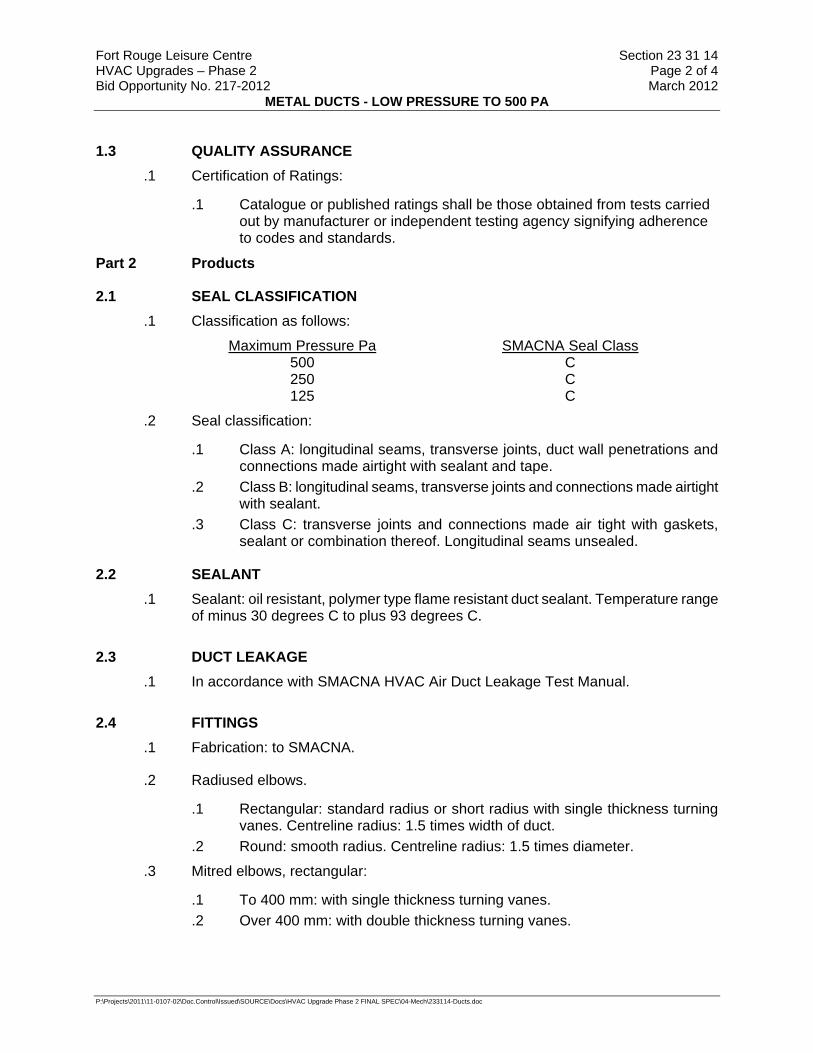
Fort Rouge Leisure Centre Section 23 31 14 HVAC Upgrades – Phase 2 Page 2 of 4 Bid Opportunity No. 217-2012 March 2012
METAL DUCTS - LOW PRESSURE TO 500 PA
P:\Projects\2011\11-0107-02\Doc.Control\Issued\SOURCE\Docs\HVAC Upgrade Phase 2 FINAL SPEC\04-Mech\233114-Ducts.doc
1.3 QUALITY ASSURANCE .1 Certification of Ratings:
.1 Catalogue or published ratings shall be those obtained from tests carried out by manufacturer or independent testing agency signifying adherence to codes and standards.
Part 2 Products
2.1 SEAL CLASSIFICATION .1 Classification as follows:
Maximum Pressure Pa SMACNA Seal Class 500 C 250 C 125 C
.2 Seal classification:
.1 Class A: longitudinal seams, transverse joints, duct wall penetrations and connections made airtight with sealant and tape.
.2 Class B: longitudinal seams, transverse joints and connections made airtight with sealant.
.3 Class C: transverse joints and connections made air tight with gaskets, sealant or combination thereof. Longitudinal seams unsealed.
2.2 SEALANT .1 Sealant: oil resistant, polymer type flame resistant duct sealant. Temperature range
of minus 30 degrees C to plus 93 degrees C.
2.3 DUCT LEAKAGE .1 In accordance with SMACNA HVAC Air Duct Leakage Test Manual.
2.4 FITTINGS .1 Fabrication: to SMACNA.
.2 Radiused elbows.
.1 Rectangular: standard radius or short radius with single thickness turning vanes. Centreline radius: 1.5 times width of duct.
.2 Round: smooth radius. Centreline radius: 1.5 times diameter.
.3 Mitred elbows, rectangular:
.1 To 400 mm: with single thickness turning vanes.
.2 Over 400 mm: with double thickness turning vanes.

Fort Rouge Leisure Centre Section 23 31 14 HVAC Upgrades – Phase 2 Page 3 of 4 Bid Opportunity No. 217-2012 March 2012
METAL DUCTS - LOW PRESSURE TO 500 PA
P:\Projects\2011\11-0107-02\Doc.Control\Issued\SOURCE\Docs\HVAC Upgrade Phase 2 FINAL SPEC\04-Mech\233114-Ducts.doc
.4 Branches:
.1 Rectangular main and branch: with radius on branch 1.5 times width of duct or 45 degrees entry on branch.
.2 Round main and branch: enter main duct at 45 degrees with conical connection.
.3 Provide volume control damper in branch duct near connection to main duct.
.4 Main duct branches: with splitter damper.
.5 Transitions:
.1 Diverging: 20 degrees maximum included angle.
.2 Converging: 30 degrees maximum included angle.
.6 Offsets:
.1 as indicated.
.7 Obstruction deflectors: maintain full cross-sectional area.
.1 Maximum included angles: as for transitions.
2.5 GALVANIZED STEEL .1 Lock forming quality: to ASTM A653/A653M, Z90 zinc coating.
.2 Thickness, fabrication and reinforcement: to SMACNA.
.3 Joints: to SMACNA.
2.6 HANGERS AND SUPPORTS .1 Hangers and Supports:
.1 Strap hangers: of same material as duct but next sheet metal thickness heavier than duct. .1 Maximum size duct supported by strap hanger: 500.
.2 Hanger configuration: to ASHRAE and SMACNA.
.3 Hangers: galvanized steel angle with galvanized steel rods to following table:
Duct Size Angle Size Rod Size (mm) (mm) (mm)
up to 750 25 x 25 x 3 6 751 to 1050 40 x 40 x 3 6
1051 to 1500 40 x 40 x 3 10 1501 to 2100 50 x 50 x 3 10 2101 to 2400 50 x 50 x 5 10 2401 and over 50 x 50 x 6 10
.4 Upper hanger attachments: .1 For concrete: manufactured concrete inserts. .2 For steel joist: manufactured joist clamp. .3 For steel beams: manufactured beam clamps:

Fort Rouge Leisure Centre Section 23 31 14 HVAC Upgrades – Phase 2 Page 4 of 4 Bid Opportunity No. 217-2012 March 2012
METAL DUCTS - LOW PRESSURE TO 500 PA
P:\Projects\2011\11-0107-02\Doc.Control\Issued\SOURCE\Docs\HVAC Upgrade Phase 2 FINAL SPEC\04-Mech\233114-Ducts.doc
Part 3 Execution
3.1 GENERAL .1 Do work in accordance with SMACNA as indicated.
.2 Do not break continuity of insulation vapour barrier with hangers or rods.
.1 Ensure diffuser is fully seated.
.3 Support risers in accordance with SMACNA.
.4 Install breakaway joints in ductwork on sides of fire separation.
.5 Install proprietary manufactured flanged duct joints in accordance with manufacturer's instructions.
3.2 HANGERS .1 Strap hangers: install in accordance with SMACNA.
.2 Angle hangers: complete with locking nuts and washers.
.3 Hanger spacing: in accordance with SMACNA:
3.3 WATERTIGHT DUCT
.1 Fit base of riser with 150 mm deep drain sump and 32 mm drain connected, with deep seal trap and discharging to open funnel drain or as indicated.
3.4 SEALING AND TAPING .1 Apply sealant to outside of joint to manufacturer's recommendations.
3.5 LEAKAGE TESTS .1 In accordance with SMACNA HVAC Duct Leakage Test Manual.
.2 Do leakage tests in sections.
.3 Make trial leakage tests as instructed to demonstrate workmanship.
.4 Do not install additional ductwork until trial test has been passed.
.5 Complete test before performance insulation or concealment Work.
END OF SECTION
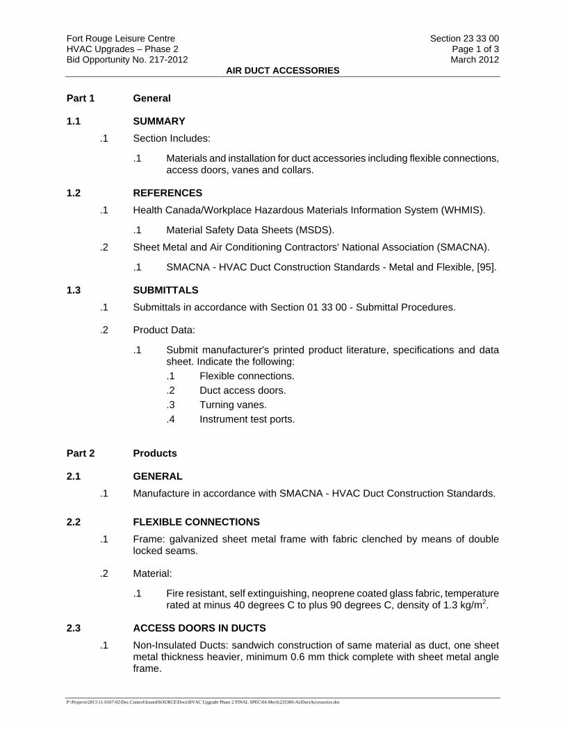
Fort Rouge Leisure Centre Section 23 33 00 HVAC Upgrades – Phase 2 Page 1 of 3 Bid Opportunity No. 217-2012 March 2012
AIR DUCT ACCESSORIES
P:\Projects\2011\11-0107-02\Doc.Control\Issued\SOURCE\Docs\HVAC Upgrade Phase 2 FINAL SPEC\04-Mech\233300-AirDuctAccessories.doc
Part 1 General
1.1 SUMMARY .1 Section Includes:
.1 Materials and installation for duct accessories including flexible connections, access doors, vanes and collars.
1.2 REFERENCES .1 Health Canada/Workplace Hazardous Materials Information System (WHMIS).
.1 Material Safety Data Sheets (MSDS).
.2 Sheet Metal and Air Conditioning Contractors' National Association (SMACNA).
.1 SMACNA - HVAC Duct Construction Standards - Metal and Flexible, [95].
1.3 SUBMITTALS .1 Submittals in accordance with Section 01 33 00 - Submittal Procedures.
.2 Product Data:
.1 Submit manufacturer's printed product literature, specifications and data sheet. Indicate the following: .1 Flexible connections. .2 Duct access doors. .3 Turning vanes. .4 Instrument test ports.
Part 2 Products
2.1 GENERAL .1 Manufacture in accordance with SMACNA - HVAC Duct Construction Standards.
2.2 FLEXIBLE CONNECTIONS .1 Frame: galvanized sheet metal frame with fabric clenched by means of double
locked seams.
.2 Material:
.1 Fire resistant, self extinguishing, neoprene coated glass fabric, temperature rated at minus 40 degrees C to plus 90 degrees C, density of 1.3 kg/m2.
2.3 ACCESS DOORS IN DUCTS .1 Non-Insulated Ducts: sandwich construction of same material as duct, one sheet
metal thickness heavier, minimum 0.6 mm thick complete with sheet metal angle frame.
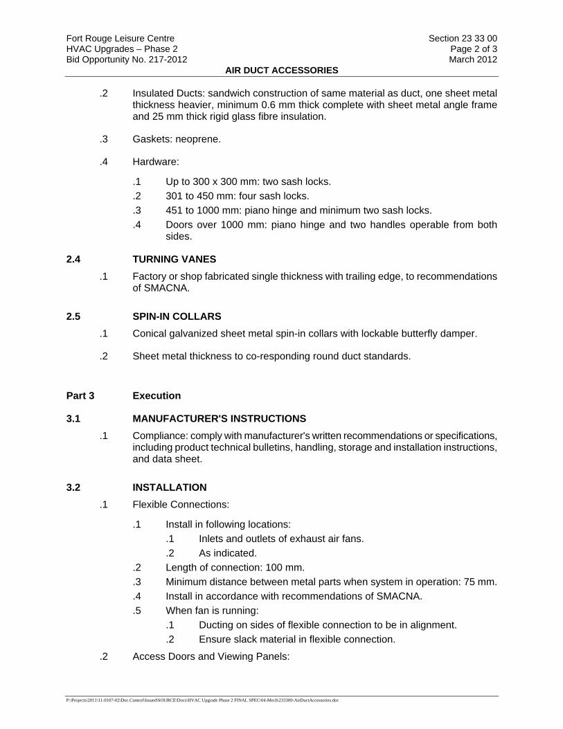
Fort Rouge Leisure Centre Section 23 33 00 HVAC Upgrades – Phase 2 Page 2 of 3 Bid Opportunity No. 217-2012 March 2012
AIR DUCT ACCESSORIES
P:\Projects\2011\11-0107-02\Doc.Control\Issued\SOURCE\Docs\HVAC Upgrade Phase 2 FINAL SPEC\04-Mech\233300-AirDuctAccessories.doc
.2 Insulated Ducts: sandwich construction of same material as duct, one sheet metal thickness heavier, minimum 0.6 mm thick complete with sheet metal angle frame and 25 mm thick rigid glass fibre insulation.
.3 Gaskets: neoprene.
.4 Hardware:
.1 Up to 300 x 300 mm: two sash locks.
.2 301 to 450 mm: four sash locks.
.3 451 to 1000 mm: piano hinge and minimum two sash locks.
.4 Doors over 1000 mm: piano hinge and two handles operable from both sides.
2.4 TURNING VANES .1 Factory or shop fabricated single thickness with trailing edge, to recommendations
of SMACNA.
2.5 SPIN-IN COLLARS .1 Conical galvanized sheet metal spin-in collars with lockable butterfly damper.
.2 Sheet metal thickness to co-responding round duct standards.
Part 3 Execution
3.1 MANUFACTURER'S INSTRUCTIONS .1 Compliance: comply with manufacturer's written recommendations or specifications,
including product technical bulletins, handling, storage and installation instructions, and data sheet.
3.2 INSTALLATION .1 Flexible Connections:
.1 Install in following locations: .1 Inlets and outlets of exhaust air fans. .2 As indicated.
.2 Length of connection: 100 mm.
.3 Minimum distance between metal parts when system in operation: 75 mm.
.4 Install in accordance with recommendations of SMACNA.
.5 When fan is running: .1 Ducting on sides of flexible connection to be in alignment. .2 Ensure slack material in flexible connection.
.2 Access Doors and Viewing Panels:

Fort Rouge Leisure Centre Section 23 33 00 HVAC Upgrades – Phase 2 Page 3 of 3 Bid Opportunity No. 217-2012 March 2012
AIR DUCT ACCESSORIES
P:\Projects\2011\11-0107-02\Doc.Control\Issued\SOURCE\Docs\HVAC Upgrade Phase 2 FINAL SPEC\04-Mech\233300-AirDuctAccessories.doc
.1 Locations: .1 Fire and smoke dampers. .2 Control dampers. .3 Devices requiring maintenance. .4 Required by code. .5 Reheat coils. .6 Elsewhere as indicated.
.3 Instrument Test Ports:
.1 General: .1 Install in accordance with recommendations of SMACNA and in
accordance with manufacturer's instructions. .2 Locate to permit easy manipulation of instruments. .3 Install insulation port extensions as required. .4 Locations:
.1 For traverse readings: .1 Ducted inlets to roof and wall exhausters. .2 Inlets and outlets of other fan systems. .3 Main and sub-main ducts. .4 And as indicated.
.2 For temperature readings: .1 At outside air intakes. .2 At inlet and outlet of coils. .3 Downstream of junctions of two converging air streams of
different temperatures. .4 And as indicated.
.4 Turning vanes:
.1 Install in accordance with recommendations of SMACNA and as indicated.
END OF SECTION
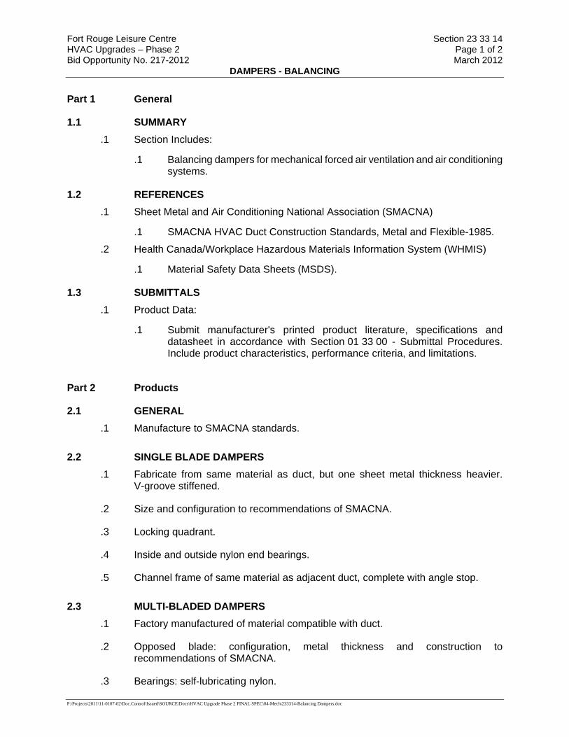
Fort Rouge Leisure Centre Section 23 33 14 HVAC Upgrades – Phase 2 Page 1 of 2 Bid Opportunity No. 217-2012 March 2012
DAMPERS - BALANCING
P:\Projects\2011\11-0107-02\Doc.Control\Issued\SOURCE\Docs\HVAC Upgrade Phase 2 FINAL SPEC\04-Mech\233314-Balancing Dampers.doc
Part 1 General
1.1 SUMMARY .1 Section Includes:
.1 Balancing dampers for mechanical forced air ventilation and air conditioning systems.
1.2 REFERENCES .1 Sheet Metal and Air Conditioning National Association (SMACNA)
.1 SMACNA HVAC Duct Construction Standards, Metal and Flexible-1985.
.2 Health Canada/Workplace Hazardous Materials Information System (WHMIS)
.1 Material Safety Data Sheets (MSDS).
1.3 SUBMITTALS .1 Product Data:
.1 Submit manufacturer's printed product literature, specifications and datasheet in accordance with Section 01 33 00 - Submittal Procedures. Include product characteristics, performance criteria, and limitations.
Part 2 Products
2.1 GENERAL .1 Manufacture to SMACNA standards.
2.2 SINGLE BLADE DAMPERS .1 Fabricate from same material as duct, but one sheet metal thickness heavier.
V-groove stiffened.
.2 Size and configuration to recommendations of SMACNA.
.3 Locking quadrant.
.4 Inside and outside nylon end bearings.
.5 Channel frame of same material as adjacent duct, complete with angle stop.
2.3 MULTI-BLADED DAMPERS .1 Factory manufactured of material compatible with duct.
.2 Opposed blade: configuration, metal thickness and construction to recommendations of SMACNA.
.3 Bearings: self-lubricating nylon.
Fort Rouge Leisure Centre Section 23 33 14 HVAC Upgrades – Phase 2 Page 2 of 2 Bid Opportunity No. 217-2012 March 2012
DAMPERS - BALANCING
P:\Projects\2011\11-0107-02\Doc.Control\Issued\SOURCE\Docs\HVAC Upgrade Phase 2 FINAL SPEC\04-Mech\233314-Balancing Dampers.doc
.4 Linkage: shaft extension with locking quadrant.
.5 Channel frame of same material as adjacent duct, complete with angle stop.
Part 3 Execution
3.1 MANUFACTURER'S INSTRUCTIONS .1 Compliance: comply with manufacturer's written recommendations or specifications,
including product technical bulletins, handling, storage and installation instructions, and datasheet.
3.2 INSTALLATION .1 Install where indicated.
.2 Install in accordance with recommendations of SMACNA and in accordance with manufacturer's instructions.
.3 Locate balancing dampers in each branch duct, for supply, return and exhaust systems.
.4 Runouts to registers and diffusers: install single blade damper located as close as possible to main ducts.
.5 Dampers: vibration free.
.6 Ensure damper operators are observable and accessible.
END OF SECTION

Fort Rouge Leisure Centre Section 23 37 20 HVAC Upgrades – Phase 2 Page 1 of 2 Bid Opportunity No. 217-2012 March 2012
LOUVRES, INTAKES AND VENTS
P:\Projects\2011\11-0107-02\Doc.Control\Issued\SOURCE\Docs\HVAC Upgrade Phase 2 FINAL SPEC\04-Mech\233720-Louvres.doc
Part 1 General
1.1 SUMMARY .1 Section Includes:
.1 Mechanical louvers; intakes; vents; and reinforcement and bracing for air vents, intakes and gooseneck hoods.
1.2 REFERENCES .1 American National Standards Institute (ANSI)/ National Fire Protection Association
(NFPA)
.1 ANSI/NFPA 96-04, Standard for Ventilation Control and Fire Protection of Commercial Cooking Operations.
.2 American Society for Testing and Materials International (ASTM)
.1 ASTM E90-04, Standard Test Method for Laboratory Measurement of Airborne Sound Transmission Loss of Building Partitions and Elements.
.3 Health Canada/Workplace Hazardous Materials Information System (WHMIS)
.1 Material Safety Data Sheets (MSDS).
.4 Sheet Metal and Air Conditioning Contractors' National Association (SMACNA)
.5 Society of Automotive Engineers (SAE)
1.3 SYSTEM DESCRIPTION .1 Performance Requirements:
.1 Catalogued or published ratings for manufactured items: obtained from tests carried out by manufacturer or those ordered by manufacturer from independent testing agency signifying adherence to codes and standards.
1.4 SUBMITTALS .1 Product Data:
.1 Submit manufacturer's printed product literature, specifications and datasheet in accordance with Section 01 33 00 - Submittal Procedures. Include product characteristics, performance criteria, and limitations.
.2 Indicate following: .1 Pressure drop. .2 Face area. .3 Free area.

Fort Rouge Leisure Centre Section 23 37 20 HVAC Upgrades – Phase 2 Page 2 of 2 Bid Opportunity No. 217-2012 March 2012
LOUVRES, INTAKES AND VENTS
P:\Projects\2011\11-0107-02\Doc.Control\Issued\SOURCE\Docs\HVAC Upgrade Phase 2 FINAL SPEC\04-Mech\233720-Louvres.doc
Part 2 Products
2.1 FIXED LOUVRES - ALUMINUM .1 Construction: welded with exposed joints ground flush and smooth.
.2 Material: extruded aluminum alloy.
.3 Blade: stormproof pattern with centre watershed in blade, reinforcing bosses and maximum blade length of 1500 mm.
.4 Frame, head, sill and jamb: 100 mm deep one piece extruded aluminum, minimum 3 mm thick with approved caulking slot, integral to unit.
.5 Mullions: at 1500 mm maximum centres.
.6 Fastenings: stainless steel SAE-194-8F with SAE-194-SFB nuts and resilient neoprene washers between aluminum and head of bolt, or between nut, ss washer and aluminum body.
.7 Screen: 19 mm intake mesh, 2 mm diameter wire aluminum birdscreen on inside face of louvres in formed U-frame.
.8 Finish: factory applied enamel. Colour: to match existing exterior wall.
.9 Acceptable Product: “E.H. Price” per louver schedule on drawings.
Part 3 Execution
3.1 MANUFACTURER'S INSTRUCTIONS .1 Compliance: comply with manufacturer's written recommendations or specifications,
including product technical bulletins, handling, storage and installation instructions, and datasheet.
3.2 INSTALLATION .1 In accordance with manufacturer's and SMACNA recommendations.
.2 Reinforce and brace as indicated.
.3 Anchor securely into opening. Seal with caulking to ensure weather tightness.
END OF SECTION
Fort Rouge Leisure Centre Section 23 52 00 HVAC Upgrades – Phase 2 Page 1 of 7 Bid Opportunity No. 217-2012 March 2012
HEATING BOILERS
P:\Projects\2011\11-0107-02\Doc.Control\Issued\SOURCE\Docs\HVAC Upgrade Phase 2 FINAL SPEC\04-Mech\235200-Boilers.doc
Part 1 General
1.1 SUMMARY .1 Section Includes:
.1 Supply, installations and commissioning of high efficiency condensing boilers as specified herein:
1.2 REFERENCES .1 American National Standards Institute (ANSI)
.1 ANSI Z21.13-2004/CSA 4.9-2004, Gas-Fired Low-Pressure Steam and Hot Water Boilers.
.2 American National Standards Institute (ANSI)/ American Society of Mechanical Engineers (ASME)
.1 ANSI/ASME Boiler and Pressure Vessel Code, Section IV, 2004.
.3 Canadian Gas Association (CGA)
.1 CAN1-3.1-77(R2001), Industrial and Commercial Gas-Fired Package Boilers.
.2 CAN/CSA-B149.1-05, Natural Gas and Propane Installation Code.
.4 Canadian Standards Association (CSA International)
.1 CSA B51-03, Boiler, Pressure Vessel, and Pressure Piping Code.
.5 Electrical and Electronic Manufacturer's Association of Canada (EEMAC)
.6 Health Canada/Workplace Hazardous Materials Information System (WHMIS)
.1 Material Safety Data Sheets (MSDS).
1.3 SUBMITTALS .1 Product Data:
.1 Submit manufacturer's printed product literature, specifications and datasheet for fixtures and equipment. Include product characteristics, performance criteria, and limitations.
.2 Shop Drawings:
.1 Submit drawings stamped and signed by professional engineer registered or licensed in the Province of Manitoba, Canada.
.2 Indicate the following: .1 General arrangement showing terminal points, instrumentation test
connections. .2 Clearances for operation, maintenance, servicing, tube cleaning,
tube replacement. .3 Foundations with loadings, anchor bolt arrangements. .4 Piping hook-ups.
Fort Rouge Leisure Centre Section 23 52 00 HVAC Upgrades – Phase 2 Page 2 of 7 Bid Opportunity No. 217-2012 March 2012
HEATING BOILERS
P:\Projects\2011\11-0107-02\Doc.Control\Issued\SOURCE\Docs\HVAC Upgrade Phase 2 FINAL SPEC\04-Mech\235200-Boilers.doc
.5 Equipment electrical drawings.
.6 Burners and controls.
.7 All miscellaneous equipment.
.8 Flame safety control system.
.9 Breeching and stack configuration.
.10 Stack emission continuous monitoring system to measure C0, 0, N0x, S0, stack temperature and smoke density of flue gases.
.3 Engineering data to include: .1 Boiler efficiency at 25%, 50%, 75%, and 100% of design capacity. .2 Radiant heat loss at 100% design capacity.
Part 2 Products
2.1 GAS FIRED CONDENSING BOILERS (B-1 and B-2) .1 GENERAL
.1 Each factory packaged low pressure hot water boiler shall be complete with all components, accessories and appurtenances necessary for a complete and operable boiler as hereinafter specified. Each unit shall be furnished factory assembled with required wiring and piping as a self-contained unit. Each unit shall be readily transported and ready for installation.
.2 Each boiler, including pressure vessel, trim, valve trains, burner, control system, and all related components, accessories and appurtenances as herein specified shall all be assembled and furnished by the boiler manufacturer. The boiler manufacturer shall provide unit responsibility for the engineering, coordination, workmanship, performance, warranties, and all field services for each factory packaged boiler as specified herein. The boiler manufacturer shall be fully responsible for all components assembled and furnished by him whether or not they are of his own manufacture.
.2 PERFORMANCE
.1 The minimum capacity of each boiler shall be to produce continuously an output of 712,500 BTU's per hour at the water outlet when fired with an input of 750,000 BTU’s per hour. Each boiler shall be capable of operating continuously at rated capacity while maintaining a CSA certified efficiency of 95%. Each boiler shall be capable of operating with a minimum outlet water temperature of 68º F.
.2 Boiler shall comply with ASME Section IV for 80 psig (max 200º F)
.3 Boiler relief valve setting shall be 552 kPa (80 psig).
.4 Boiler outlet water temperature shall be 82o C (180o F) (200º F max).
.5 Boiler inlet water temperature shall be 27o C (80o F).
.6 Boiler design water flow rate shall be 4.7 L/s (75 GPM).
.7 Fuel shall be natural gas with an assumed higher heating value of 1,030 Btu/Cu Ft and an assumed specific gravity of 0.60 (relative to air). Natural gas shall be supplied at a pressure of no less than 3.5 in. w.c. to the inlet gas valve. Maximum inlet gas pressure shall not exceed 14 in. w.c.

Fort Rouge Leisure Centre Section 23 52 00 HVAC Upgrades – Phase 2 Page 3 of 7 Bid Opportunity No. 217-2012 March 2012
HEATING BOILERS
P:\Projects\2011\11-0107-02\Doc.Control\Issued\SOURCE\Docs\HVAC Upgrade Phase 2 FINAL SPEC\04-Mech\235200-Boilers.doc
.8 Power voltage shall be 120 VAC, 1-phase, 60 hertz. Control voltage shall be 24 VAC (transformer to be supplied by boiler manufacturer). In accordance with American Boiler Manufacturers Association (ABMA), or ANSI Z21.13/CSA 4.9 (gas burning) testing procedures.
.3 BOILER DESIGN
.1 Hot water boiler shall consist of a horizontal, cast aluminum heat exchanger complete with trim, valve trains, burner, and boiler control system. The boiler manufacturer shall fully coordinate the boiler as to the interaction of its elements with the burner and the boiler control system in order to provide the required capacities, efficiencies, and performance as specified.
.2 Boiler heat exchanger shall be cast aluminum, counter-flow design for maximum heat transfer with the multiple sections arranged in a reverse return configuration to assure balanced flow through each section.
.3 Contractor must, when filling the system, verify that the pH level is maintained between 6.0 and 8.5.
.4 All boiler pressure parts shall be constructed in accordance with the latest revision of the ASME Boiler and Pressure Vessel Code, Section IV, and shall be so stamped.
.5 Boiler heat exchanger headers shall be fabricated steel and be completely removable for inspection. Seals shall be EPDM, rated for 400 deg F service. Push nipples or gaskets between the sections are not permitted.
.6 Boiler shall be enclosed with a single wall outer casing. It shall be fabricated from a minimum 16 gauge carbon steel. The front and top wall shall be secured in place with ¼ -20 NC bolts (sheet metal screws are not acceptable).The complete outer casing shall be finished, inside and out, with a powder coat finish. The composite structure of the boiler combustion chamber, insulating air gap and outer casing shall be of such thickness and materials to assure an outer casing temperature of not more than 50oF above ambient temperature when the boiler is operated at full rated load.
.7 An observation port shall be located on the boiler to allow for observation of the burner flame.
.8 Flue gas outlet shall be located on the rear of the boiler. Boiler to be certified for installation with Category IV venting (stack) as defined in NFPA 54 (ANSI Z221), latest edition. Contractor must provide venting (stack) certified for installation on a Category IV appliance.
.4 BOILER CONNECTIONS
.1 Boiler shall be provided with all necessary inlet and outlet connections. Boiler connections shall be as follows: .1 One (1) water supply outlet, 50mm (2”) Victaulic with threaded pipe
adapter. .2 One (1) water return inlet, 50mm (2”) Victaulic with threaded pipe
adapter. .3 One (1) relief valve outlet, 25mm (1”) NPT. .4 One (1) flue gas vent outlet, 150mm (6”) diameter. .5 One (1) fuel gas inlet, 25mm (1”) size, FPT.
Fort Rouge Leisure Centre Section 23 52 00 HVAC Upgrades – Phase 2 Page 4 of 7 Bid Opportunity No. 217-2012 March 2012
HEATING BOILERS
P:\Projects\2011\11-0107-02\Doc.Control\Issued\SOURCE\Docs\HVAC Upgrade Phase 2 FINAL SPEC\04-Mech\235200-Boilers.doc
.5 BOILER TRIM
.1 Boiler shall be provided with all necessary trim. Boiler trim shall be as follows: .1 Safety relief valve shall be provided in compliance with the ASME
code. Contractor to pipe to acceptable drain. .2 Water pressure-temperature gauge. .3 Primary low water flow fuel cutoff (probe type with manual reset). .4 Manual reset high limit water temperature controller. .5 Operating temperature control to control the sequential operation of
the burner. .6 Separate inlet and outlet water temperature sensors capable of
monitoring flow. .7 Exhaust temperature sensor. .8 A secondary float type low water cut off shall be supplied by
contractor.
.6 BOILER FUEL BURNING SYSTEM
.1 The boiler manufacturer shall furnish each boiler with an integral, power type, straight gas, fully automatic fuel burner. The fuel burner shall be an assembly of gas burner, combustion air blower, valve train, and ignition system. The burner manufacturer shall fully coordinate the burner as to the interaction of its elements with the boiler heat exchanger and the boiler control system in order to provide the required capacities, efficiencies, and performance as specified.
.2 Each burner shall be provided with an integral gas firing combustion head.
.3 Each burner shall provide adequate turbulence and mixing to achieve proper combustion without producing smoke or producing combustibles in the flue gases.
.4 Each boiler shall be provided with an integral variable speed power blower to premix combustion air and fuel within the blower. The combustion air blower shall have sufficient capacity at the rated firing rate to provide air for stoichiometric combustion plus the necessary excess air. Static and total pressure capability shall comply with the requirements of the boiler. The blower shall be a maximum of 300 watts and operate at 6000 RPM maximum without undue vibration and noise and shall be designed and constructed for exposure to temperatures normal to its location on the boiler. The operating fan speed will be tachometer sensed and be capable of being displayed at the LED display.
.5 Each burner shall of the radial-fired (down-fired) type and constructed of steel with a stainless steel inner and stainless steel mesh outer screen.
.6 Each boiler shall be provided with a “Full Modulating” firing control system whereby the firing rate is infinitely proportional at any firing rate between 20% and 100% as determined by the pulse width modulation input control signal. Both fuel input and air input must be sequenced in unison to the appropriate firing rate without the use of mechanical linkage.

Fort Rouge Leisure Centre Section 23 52 00 HVAC Upgrades – Phase 2 Page 5 of 7 Bid Opportunity No. 217-2012 March 2012
HEATING BOILERS
P:\Projects\2011\11-0107-02\Doc.Control\Issued\SOURCE\Docs\HVAC Upgrade Phase 2 FINAL SPEC\04-Mech\235200-Boilers.doc
.7 The Micro Processor shall use a Proportional Integral Algorithm to determine the firing rate. The control must have the following capabilities:
.1 Maintain single set point .2 Reset the set point based on outdoor air temperature. .3 Boiler shutdown based on outdoor air temperature .4 Internal dual set point program with an external switchover. (e.g. -
night setback w/external clock, supplied by others) .5 Alarm relay for any for any manual reset alarm function. .6 Programmable Low Fire Delay to prevent short cycling based on a
time and temperature factor for release to modulation. .7 LED Display showing current supply and return temperatures,
current set points as well as differential set points. It must also display any fault codes whether automatically reset or manually reset.
.8 Local Manual Operation.
.9 Remote Control System (Building Management / Sequencer Control) - The boiler control shall be capable of accepting a 0 -10vdc remote external analog signal to control the firing rate
.10 On board Domestic Hot Water Priority capable of changing from the heating pump to the DHW pump as well as changing the boiler set point from a heating temperature to a higher set point temperature to satisfy the DHW system and then return to the heating mode.
.11 Computer (PC) interface for programming and monitoring all functions
.7 MAIN GAS VALVE TRAIN
.1 Each boiler shall be provided with an integral main gas valve train. The main gas valve trains shall be factory assembled, piped, and wired. Each gas valve train shall include at least the following:
.1 Two (2) manual shutoff valves. .2 Two (2) safety shutoff valves. Valves equipped with dual solenoids
that can independently energized for leak testing. .3 Air – Gas ratio control (maximum inlet pressure 14 in. w.c.). .4 One (1) low gas pressure switch (manual reset). .5 One (1) high gas pressure switch (manual reset). .6 Two (2) pressure test ports
.8 IGNITION SYSTEM
.1 Boiler shall be equipped for direct spark ignition
.9 COMBUSTION AIR CONTROL SYSTEM
.1 Boiler shall be provided with an integral combustion air control system. The combustion air system shall be factory assembled. Each combustion air control system shall include at least the following:
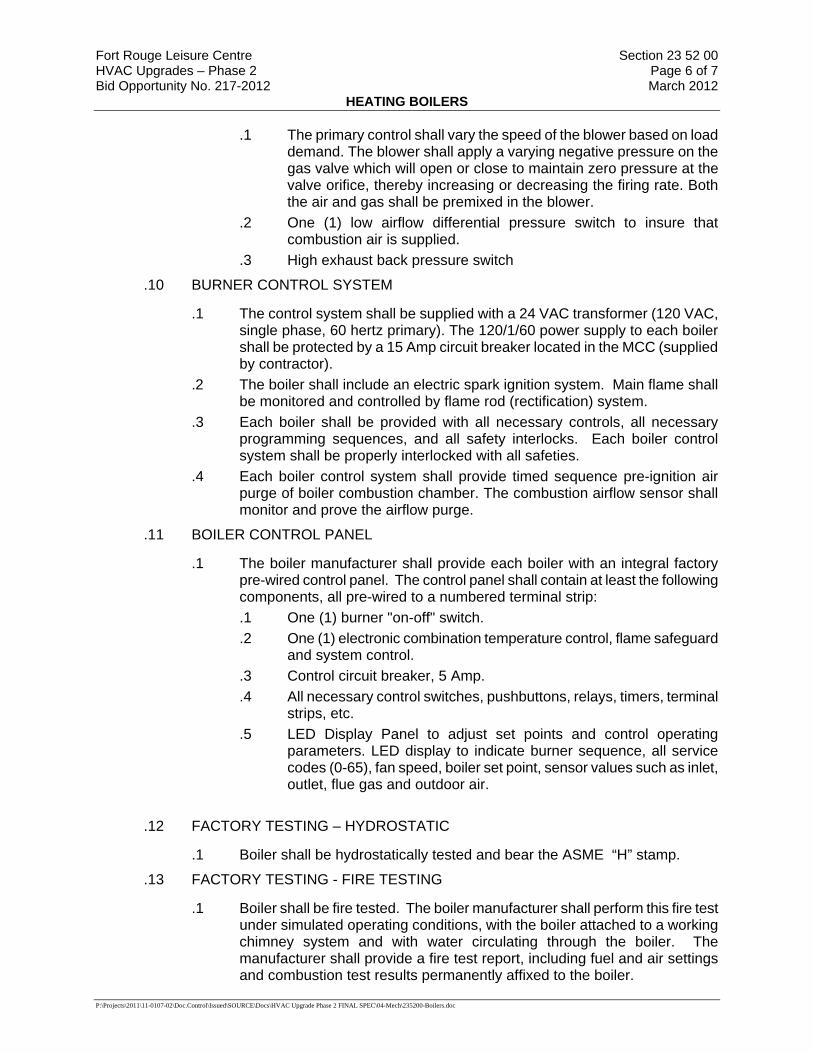
Fort Rouge Leisure Centre Section 23 52 00 HVAC Upgrades – Phase 2 Page 6 of 7 Bid Opportunity No. 217-2012 March 2012
HEATING BOILERS
P:\Projects\2011\11-0107-02\Doc.Control\Issued\SOURCE\Docs\HVAC Upgrade Phase 2 FINAL SPEC\04-Mech\235200-Boilers.doc
.1 The primary control shall vary the speed of the blower based on load demand. The blower shall apply a varying negative pressure on the gas valve which will open or close to maintain zero pressure at the valve orifice, thereby increasing or decreasing the firing rate. Both the air and gas shall be premixed in the blower.
.2 One (1) low airflow differential pressure switch to insure that combustion air is supplied.
.3 High exhaust back pressure switch
.10 BURNER CONTROL SYSTEM
.1 The control system shall be supplied with a 24 VAC transformer (120 VAC, single phase, 60 hertz primary). The 120/1/60 power supply to each boiler shall be protected by a 15 Amp circuit breaker located in the MCC (supplied by contractor).
.2 The boiler shall include an electric spark ignition system. Main flame shall be monitored and controlled by flame rod (rectification) system.
.3 Each boiler shall be provided with all necessary controls, all necessary programming sequences, and all safety interlocks. Each boiler control system shall be properly interlocked with all safeties.
.4 Each boiler control system shall provide timed sequence pre-ignition air purge of boiler combustion chamber. The combustion airflow sensor shall monitor and prove the airflow purge.
.11 BOILER CONTROL PANEL
.1 The boiler manufacturer shall provide each boiler with an integral factory pre-wired control panel. The control panel shall contain at least the following components, all pre-wired to a numbered terminal strip: .1 One (1) burner "on-off" switch. .2 One (1) electronic combination temperature control, flame safeguard
and system control. .3 Control circuit breaker, 5 Amp. .4 All necessary control switches, pushbuttons, relays, timers, terminal
strips, etc. .5 LED Display Panel to adjust set points and control operating
parameters. LED display to indicate burner sequence, all service codes (0-65), fan speed, boiler set point, sensor values such as inlet, outlet, flue gas and outdoor air.
.12 FACTORY TESTING – HYDROSTATIC
.1 Boiler shall be hydrostatically tested and bear the ASME “H” stamp.
.13 FACTORY TESTING - FIRE TESTING
.1 Boiler shall be fire tested. The boiler manufacturer shall perform this fire test under simulated operating conditions, with the boiler attached to a working chimney system and with water circulating through the boiler. The manufacturer shall provide a fire test report, including fuel and air settings and combustion test results permanently affixed to the boiler.

Fort Rouge Leisure Centre Section 23 52 00 HVAC Upgrades – Phase 2 Page 7 of 7 Bid Opportunity No. 217-2012 March 2012
HEATING BOILERS
P:\Projects\2011\11-0107-02\Doc.Control\Issued\SOURCE\Docs\HVAC Upgrade Phase 2 FINAL SPEC\04-Mech\235200-Boilers.doc
.14 Dimensions: 711mm W x 1082mm L x 1387mm H (28" Wx 42 5/8" L x 54 5/8" H) Dimensions shall not be exceeded.
.15 Operating Weight: 315 kg (695 lbs.)
.16 Provide condensate neutralizer kit.
.17 Acceptable Product: “Patterson-Kelley” Model: C-750.
Part 3 Execution
3.1 MANUFACTURER'S INSTRUCTIONS .1 Compliance: comply with manufacturer's written recommendations or specifications,
including product technical bulletins, handling, storage and installation instructions, and datasheet.
3.2 INSTALLATION .1 Install in accordance with ANSI/ASME Boiler and Pressure Vessels Code Section
IV, regulations of Province having jurisdiction, except where specified otherwise, and manufacturers recommendations.
.2 Make required piping connections to inlets and outlets recommended by boiler manufacturer.
.3 Maintain clearances as indicated or if not indicated, as recommended by manufacturer for operation, servicing and maintenance without disruption of operation of any other equipment/system.
.4 Mount unit level.
.5 Natural gas fired installations - in accordance with CAN/CSA-B149.1.
.6 Pipe condensate through the neutralizer to the drain.
3.3 MOUNTINGS AND ACCESSORIES .1 Safety valves and relief valves:
.1 Run separate discharge from each valve.
.2 Terminate discharge pipe as indicated.
.3 Run drain pipe from each valve outlet and drip pan elbow to above nearest drain.
.2 Blowdown valves:
.1 Run discharge to terminate as indicated.
END OF SECTION
Fort Rouge Leisure Centre Section 23 73 11 HVAC Upgrades – Phase 2 Page 1 of 11 Bid Opportunity No. 217-2012 March 2012
AIR HANDLING UNITS
P:\Projects\2011\11-0107-02\Doc.Control\Issued\SOURCE\Docs\HVAC Upgrade Phase 2 FINAL SPEC\04-Mech\237311-AHU.doc
Part 1 General
1.1 SUMMARY .1 Supply, install, and commission air handling unit as specified herein.
1.2 REFERENCES .1 American National Standards Institute/Air-Conditioning and Refrigeration Institute
(ANSI/ARI)
.1 ANSI/ARI 430-99, Central Station Air Handling Units.
.2 Canadian General Standards Board (CGSB)
.1 CAN/CGSB 1.181-99, Ready-Mixed Organic Zinc-Rich Coating.
1.3 SHOP DRAWINGS AND PRODUCT DATA .1 Submit shop drawings and product data in accordance with CWSCS.
.2 Indicate following: fan, motor drive, voltage, dimensions, total cooling, sensible cooling; include performance data.
1.4 CLOSEOUT SUBMITTALS .1 Provide maintenance data for incorporation into manual specified in Section
01 78 00 - Closeout Submittals.
1.5 EXTRA MATERIALS .1 Provide list of individual manufacturer's recommended spare parts for equipment
such as bearings and seals, and addresses of suppliers, together with list of specialized tools necessary for adjusting, repairing or replacing, for placement into operating manual.
.2 Spare filters: in addition to filters installed immediately prior to acceptance by Contract Administrator, supply 5 complete sets of filters for each filter unit or filter bank.
Part 2 Products
2.1 SPLIT SYSTEM AIR HANDLING UNIT (AHU-3 / CU-3) .1 AIR HANDLING UNIT AHU-3:
.1 Factory assembled, split-system air handling unit. Contained within the unit enclosure shall be supply fan, return fan, coils, filters and dampers.
.2 The unit shall be controlled by a DDC System per Section 230933.
.2 Unit Cabinet:
.1 Unit casing shall be of minimum 18 gauge (1.3mm) satin coat galvanized sheet metal. Surfaces shall be cleaned with a degreasing solvent to remove oil and metal oxides and primed with a two-part acid based etching primer.

Fort Rouge Leisure Centre Section 23 73 11 HVAC Upgrades – Phase 2 Page 2 of 11 Bid Opportunity No. 217-2012 March 2012
AIR HANDLING UNITS
P:\Projects\2011\11-0107-02\Doc.Control\Issued\SOURCE\Docs\HVAC Upgrade Phase 2 FINAL SPEC\04-Mech\237311-AHU.doc
Finish coat shall be an electrostatically applied enamel, to all exposed surfaces. All unprotected metal and welds shall be factory coated.
.2 All walls, roofs and floors shall be of formed construction, with at least two breaks at each joint. Joints shall be secured by sheet metal screws or pop rivets. Wall and floor joints shall be broken in and on all outdoor units roof joints broken out (exposed) for rigidity. All joints shall be caulked with a water resistant sealant.
.3 Units shall be provided with access doors to the following components: fans and motors, filters, dampers and operators, access plenums, electrical control panels, burner compressor compartments. Access doors shall be large enough for easy access. Removal of screwed wall panels will not be acceptable.
.4 All units shall be internally insulated with 1"(25mm) thick 1 1/2 lb./cu.ft. (24 kg./cu.m.) density, neoprene coated fibre glass thermal insulation. 1 1/2 lb./cu.ft. (24 kg/cu.m.)insulation shall be secured to metal panels with a fire retardant adhesive and welded steel pins at 16" (400mm) o/c. All longitudinal insulation joints and butt ends shall be covered by a sheet metal break to prevent erosion of exposed edges. Drain pans and all floor areas shall be insulated on the underside.
.5 Cooling coil drain pans shall be fabricated of stainless steel and are an integral part of the floor paneling, a minimum of 2" (51mm) deep, with welded corners. Drain pans shall extend a minimum of 6" (152mm) downstream of coil face and be provided with a 1 ½" (38mm) S.S. M.P.T. drain connection. Drain pans must have a fast pan and be sloped and pitched such that there is no standing water. Intermediate fast pans shall be provided between cooling coils where required for effective moisture removal.
.3 Fans:
.1 Centrifugal fans shall be rated in accordance with AMCA Standard Test Code, Bulletin 210. Fan manufacturer shall be a member of AMCA. All fans and fan assemblies shall be dynamically balanced during factory test run. Fan shafts shall be selected for stable operation at least 20% below the first critical RPM. Fan shafts shall be provided with a rust inhibiting coating.
.2 Single low pressure forward curved fans shall be equipped with greaseable pillow block bearings, supported on a rigid structural steel frame.
.3 Provide full section return air fan(s) as scheduled. The use of power exhaust propeller or centrifugal fan arrangements will not be considered. .1 Allow provisions for variable air volume fan control via adjustable
frequency drive (supplied and mounted by others). .4 Motor, fan bearings and drive assembly shall be located inside the fan
plenum to minimize bearing wear and to allow for internal vibration isolation of the fan-motor assembly, where required. Motor mounting shall be adjustable to allow for variations in belt tension.
.5 Fan-motor assemblies shall be provided with vibration isolators. Isolators shall be bolted to steel channel welded to unit floor, which is welded to the structural frame of the unit. The isolators shall be neoprene-in-shear type for single 9" (230mm) to 15" (380mm) diameters forward curve fans. All other fans shall incorporate vertical spring type isolators with leveling bolts, bridge bearing waffled pads with minimum 1" (25mm) static deflection designed to

Fort Rouge Leisure Centre Section 23 73 11 HVAC Upgrades – Phase 2 Page 3 of 11 Bid Opportunity No. 217-2012 March 2012
AIR HANDLING UNITS
P:\Projects\2011\11-0107-02\Doc.Control\Issued\SOURCE\Docs\HVAC Upgrade Phase 2 FINAL SPEC\04-Mech\237311-AHU.doc
achieve high isolation efficiency. Fans shall be attached to the discharge panel by a polyvinyl chloride coated polyester woven fabric, with a sealed double locking fabric to metal connection.
.6 Fan motors shall be ODP super high efficiency type. The motors shall be
inverter duty rated suitable for VFD operation.
.4 Coils:
.1 Coils shall be 5/8” or 1/2" O.D. as manufactured by Engineered Air.
.2 Fins constructed of aluminum or copper shall be rippled for maximum heat transfer and shall be mechanically bonded to the tubes by mechanical expansion of the tubes. The coils shall have a galvanized steel casing. All coils shall be factory tested with air at 300 psig (2070 kPa) while immersed in an illuminated water tank.
.3 Refrigerant evaporator type coils shall be equipped with distributors connected to the coil by copper tubes. Where a hot gas bypass is required, the inlet shall be at the refrigerant distributor. Solenoid valves, expansion valves, and related accessories are to be provided and installed by the refrigeration contractor.
.4 Refrigerant coils with multiple compressors shall be alternate tube circuited in order to distribute the cooling effect over the entire coil face at reduced load conditions. Provision for use of thermal expansion valves must be included for variable air volume and/or make-up air applications.
.5 Dampers:
.1 Damper frames shall be U - shaped galvanized metal sections securely screwed or welded to the air handling unit chassis. Pivot rods of 1/2" (13mm) aluminum shall turn in nylon or bronze bushings. Rods shall be secured to the blade by means of straps and set screws.
.2 Blades shall be 18 gauge (1.3mm) galvanized metal with two breaks on each edge and three breaks on centerline for rigidity. The pivot rod shall "nest" in the centerline break. Damper edges shall interlock. Maximum length of damper between supports shall be 48”(1219 mm). Damper linkage brackets shall be constructed of galvanized metal.
.3 Dampers shall include blade ends sealed with an adhesive backed foamed polyurethane gasketting. Outdoor air dampers also include an all weather PVC seal fastened with a positive lock grip and pliable overlap edge on entering air side of interlocking edges. Dampers are interlocked from the center.
.4 Mixing dampers shall be parallel blade type.
.5 Damper actuators and control by section 230933.
.6 Filter Section:
.1 Factory-installed, low velocity, throwaway 50mm (2”) thick fibreglass filters, commercially available sizes, use one size filter.
.2 Filter face velocity shall not exceed 1.6 m/s (320 FPM) at nominal airflows.
.3 Filters shall be accessible through access panel with “no-tool” removal.
Fort Rouge Leisure Centre Section 23 73 11 HVAC Upgrades – Phase 2 Page 4 of 11 Bid Opportunity No. 217-2012 March 2012
AIR HANDLING UNITS
P:\Projects\2011\11-0107-02\Doc.Control\Issued\SOURCE\Docs\HVAC Upgrade Phase 2 FINAL SPEC\04-Mech\237311-AHU.doc
.7 Factory/Field Supplied Controls
.1 Provide a system of motor control include terminal blocks for wiring of remote VFDs (VFD’s supplied by division 26). VFDs shall be powered from the air handling unit (wiring to and from the VFD to the air handling unit is by division 26). VFDs are controlled by section 230933.
.2 Fire alarm circuits (where required) shall be powered from a relay in unit circuitry.
.3 Automatic controls shall be housed in a control panel mounted in or on the air handling unit, which will meet that standard of the specific installation.
.8 ROOF MOUNTED REMOTE CONDENSING UNIT (CU-3)
.1 Compressors shall be hermetic type, 3600 RPM, set on resilient neoprene mounts and complete with line voltage break internal overload protection, internal pressure relief valve and crankcase heater.
.2 Air Cooled Condenser .1 Condenser coils shall be copper tube type, mechanically expanded
into aluminum fins. Coils shall be factory tested with air at 300 psig (2070 kPa) while immersed in an illuminated water tank.
.2 Condenser fans shall be direct driven propeller type arranged for vertical draw through airflow. Motors shall be weather resistant type, with integral overload protection and designed for vertical shaft condenser fan applications. Fan and motor assemblies shall be mounted on a formed orifice plate for optimum efficiency with minimum noise level.
.3 Condenser to form an integral part of the unit.
.3 Split System Condensing Units
.1 Condensing units shall be CETL approved. Condensing units shall be designed for a minimum of 15°F(8°C) liquid subcooling. Condensing units shall operate down to 50°F(10°C) as standard. Multiple compressor/condenser circuits shall be separate from each other. Suction and liquid lines shall be extended to the outside of the cabinet. Service ports fitted with Schraeder fittings shall be connected to the suction and discharge lines for charging or pressure gauge readings. Semi-hermetic units shall also incorporate liquid line service ports and liquid line manual shutoff valves.
.2 Controls for hermetic compressor units shall include compressor and condenser fan motor contactors, control circuit transformer, cooling relays, non-recycling pumpdown relays, ambient compressor lockout, manual reset high pressure controls and automatic reset low pressure controls. Head pressure actuated fan cycling control shall be provided on all multiple condenser fan units.
.3 Provide five minute anti-cycle timers.
.4 Provide interstage time delay timers.
.5 Provide hot gas bypass connection on the lead compressor.
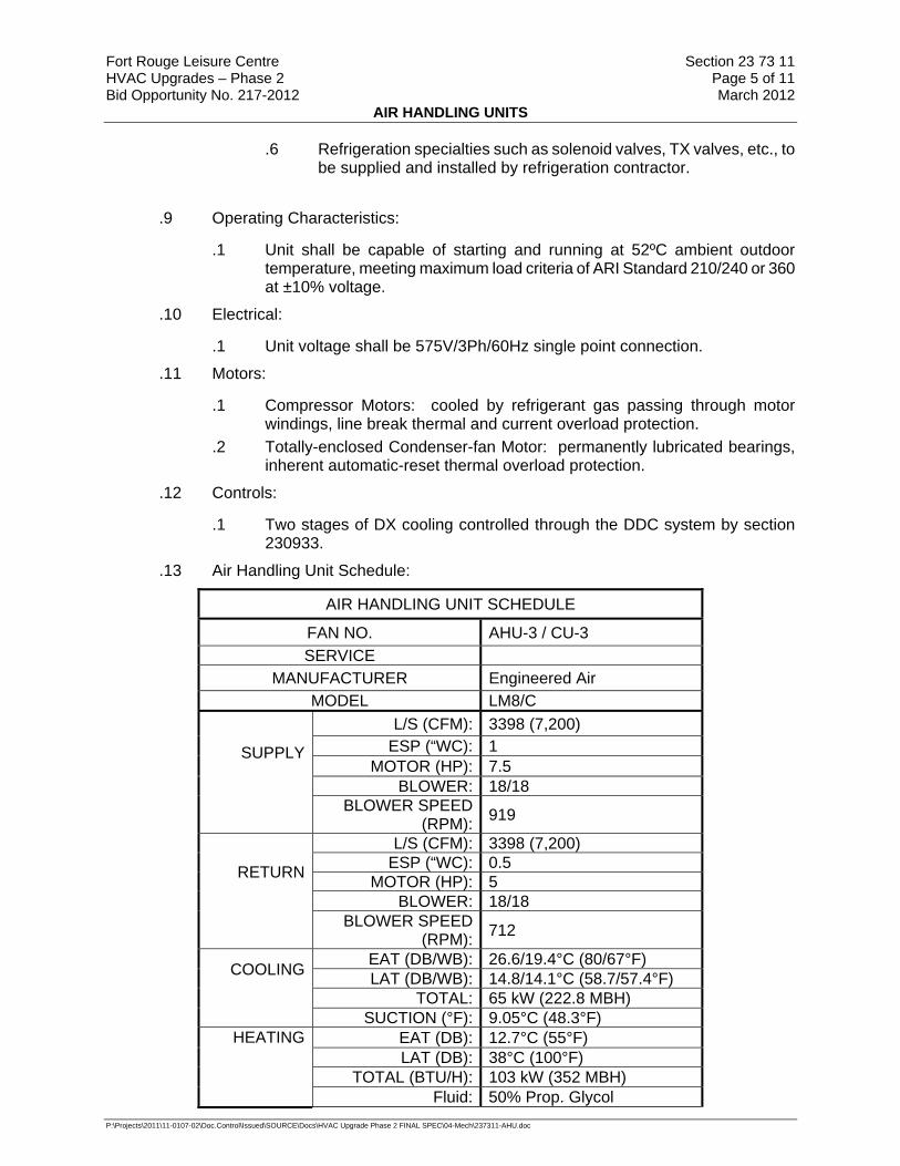
Fort Rouge Leisure Centre Section 23 73 11 HVAC Upgrades – Phase 2 Page 5 of 11 Bid Opportunity No. 217-2012 March 2012
AIR HANDLING UNITS
P:\Projects\2011\11-0107-02\Doc.Control\Issued\SOURCE\Docs\HVAC Upgrade Phase 2 FINAL SPEC\04-Mech\237311-AHU.doc
.6 Refrigeration specialties such as solenoid valves, TX valves, etc., to be supplied and installed by refrigeration contractor.
.9 Operating Characteristics:
.1 Unit shall be capable of starting and running at 52ºC ambient outdoor temperature, meeting maximum load criteria of ARI Standard 210/240 or 360 at ±10% voltage.
.10 Electrical:
.1 Unit voltage shall be 575V/3Ph/60Hz single point connection.
.11 Motors:
.1 Compressor Motors: cooled by refrigerant gas passing through motor windings, line break thermal and current overload protection.
.2 Totally-enclosed Condenser-fan Motor: permanently lubricated bearings, inherent automatic-reset thermal overload protection.
.12 Controls:
.1 Two stages of DX cooling controlled through the DDC system by section 230933.
.13 Air Handling Unit Schedule:
AIR HANDLING UNIT SCHEDULE
FAN NO. AHU-3 / CU-3 SERVICE
MANUFACTURER Engineered Air MODEL LM8/C
L/S (CFM): 3398 (7,200) ESP (“WC): 1
MOTOR (HP): 7.5 SUPPLY
BLOWER: 18/18
BLOWER SPEED (RPM): 919
L/S (CFM): 3398 (7,200) ESP (“WC): 0.5
MOTOR (HP): 5 RETURN
BLOWER: 18/18
BLOWER SPEED (RPM): 712
EAT (DB/WB): 26.6/19.4°C (80/67°F) LAT (DB/WB): 14.8/14.1°C (58.7/57.4°F)
TOTAL: 65 kW (222.8 MBH)
COOLING
SUCTION (°F): 9.05°C (48.3°F)
EAT (DB): 12.7°C (55°F) LAT (DB): 38°C (100°F)
TOTAL (BTU/H): 103 kW (352 MBH)
HEATING
Fluid: 50% Prop. Glycol
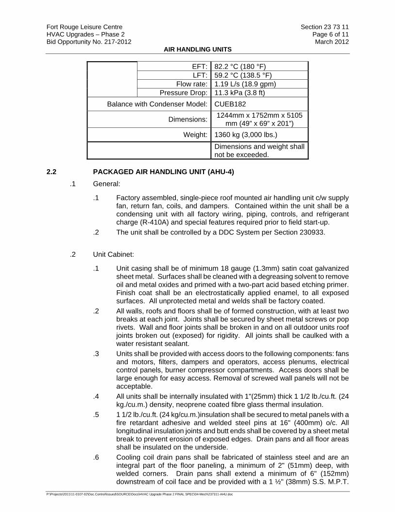
Fort Rouge Leisure Centre Section 23 73 11 HVAC Upgrades – Phase 2 Page 6 of 11 Bid Opportunity No. 217-2012 March 2012
AIR HANDLING UNITS
P:\Projects\2011\11-0107-02\Doc.Control\Issued\SOURCE\Docs\HVAC Upgrade Phase 2 FINAL SPEC\04-Mech\237311-AHU.doc
EFT: 82.2 °C (180 °F) LFT: 59.2 °C (138.5 °F)
Flow rate: 1.19 L/s (18.9 gpm) Pressure Drop: 11.3 kPa (3.8 ft)
Balance with Condenser Model: CUEB182
Dimensions: 1244mm x 1752mm x 5105 mm (49” x 69” x 201”)
Weight: 1360 kg (3,000 lbs.)
Dimensions and weight shall not be exceeded.
2.2 PACKAGED AIR HANDLING UNIT (AHU-4) .1 General:
.1 Factory assembled, single-piece roof mounted air handling unit c/w supply fan, return fan, coils, and dampers. Contained within the unit shall be a condensing unit with all factory wiring, piping, controls, and refrigerant charge (R-410A) and special features required prior to field start-up.
.2 The unit shall be controlled by a DDC System per Section 230933.
.2 Unit Cabinet:
.1 Unit casing shall be of minimum 18 gauge (1.3mm) satin coat galvanized sheet metal. Surfaces shall be cleaned with a degreasing solvent to remove oil and metal oxides and primed with a two-part acid based etching primer. Finish coat shall be an electrostatically applied enamel, to all exposed surfaces. All unprotected metal and welds shall be factory coated.
.2 All walls, roofs and floors shall be of formed construction, with at least two breaks at each joint. Joints shall be secured by sheet metal screws or pop rivets. Wall and floor joints shall be broken in and on all outdoor units roof joints broken out (exposed) for rigidity. All joints shall be caulked with a water resistant sealant.
.3 Units shall be provided with access doors to the following components: fans and motors, filters, dampers and operators, access plenums, electrical control panels, burner compressor compartments. Access doors shall be large enough for easy access. Removal of screwed wall panels will not be acceptable.
.4 All units shall be internally insulated with 1"(25mm) thick 1 1/2 lb./cu.ft. (24 kg./cu.m.) density, neoprene coated fibre glass thermal insulation.
.5 1 1/2 lb./cu.ft. (24 kg/cu.m.)insulation shall be secured to metal panels with a fire retardant adhesive and welded steel pins at 16" (400mm) o/c. All longitudinal insulation joints and butt ends shall be covered by a sheet metal break to prevent erosion of exposed edges. Drain pans and all floor areas shall be insulated on the underside.
.6 Cooling coil drain pans shall be fabricated of stainless steel and are an integral part of the floor paneling, a minimum of 2" (51mm) deep, with welded corners. Drain pans shall extend a minimum of 6" (152mm) downstream of coil face and be provided with a 1 ½" (38mm) S.S. M.P.T.

Fort Rouge Leisure Centre Section 23 73 11 HVAC Upgrades – Phase 2 Page 7 of 11 Bid Opportunity No. 217-2012 March 2012
AIR HANDLING UNITS
P:\Projects\2011\11-0107-02\Doc.Control\Issued\SOURCE\Docs\HVAC Upgrade Phase 2 FINAL SPEC\04-Mech\237311-AHU.doc
drain connection. Drain pans must have a fast pan and be sloped and pitched such that there is no standing water. Intermediate fast pans shall be provided between cooling coils where required for effective moisture removal.
.7 Provide a full height, insulated piping vestibule integral to the unit casing.
.8 Air handling units shall be weatherproofed and equipped for installation outdoors. This shall include generally for the prevention of infiltration of rain and snow into the unit, louvers or hoods on air intakes and exhaust openings with 1"(25mm) galvanized inlet screens; rain gutters or diverters over all access doors; all joints caulked with a water resistant sealant; roof joints turned up 2" (51mm) with three break interlocking design; outer wall panels extend a minimum of ¼”(6mm) below the floor panel; drain trap(s) connections for field supply and installation of drain traps.
.9 Units mounted on roof curbs incorporate welded floor to base construction. Floors are of three break upstanding design with welded corners and free of penetrations. Unit underside joints are caulked.
.10 Provide full perimeter roof mounting curb of heavy gauge sheet metal, minimum of 12”(305mm) high, and complete with wood nailer, neoprene sealing strip, and fully welded "Z" bar with 1" (25mm) upturn on inner perimeter, to provide a complete seal against the elements. External insulation of the roof-mounting curb shall be provided by the Roofing Subcontractor. Hydronic heating coil piping vestibule shall be incorporated into the design of the roof curb.
.3 Fans:
.1 Centrifugal fans shall be rated in accordance with AMCA Standard Test Code, Bulletin 210. Fan manufacturer shall be a member of AMCA. All fans and fan assemblies shall be dynamically balanced during factory test run. Fan shafts shall be selected for stable operation at least 20% below the first critical RPM. Fan shafts shall be provided with a rust inhibiting coating.
.2 Single low pressure forward curved fans shall be equipped with greaseable pillow block bearings, supported on a rigid structural steel frame.
.3 Provide full section return air fan(s) as scheduled. The use of power exhaust propeller or centrifugal fan arrangements will not be considered.
.1 Allow provisions for variable air volume fan control via adjustable
frequency drive (supplied and mounted by division 26). .2 Line and load reactors required for 575 volt applications (by division
26). .4 Minimum air flow rate of 40% on DX. .5 Motor, fan bearings and drive assembly shall be located inside the fan
plenum to minimize bearing wear and to allow for internal vibration isolation of the fan-motor assembly, where required. Motor mounting shall be adjustable to allow for variations in belt tension.
.6 Fan-motor assemblies shall be provided with vibration isolators. Isolators shall be bolted to steel channel welded to unit floor, which is welded to the structural frame of the unit. The isolators shall be neoprene-in-shear type for single 9" (230mm) to 15" (380mm) diameters forward curve fans. All other fans shall incorporate vertical spring type isolators with leveling
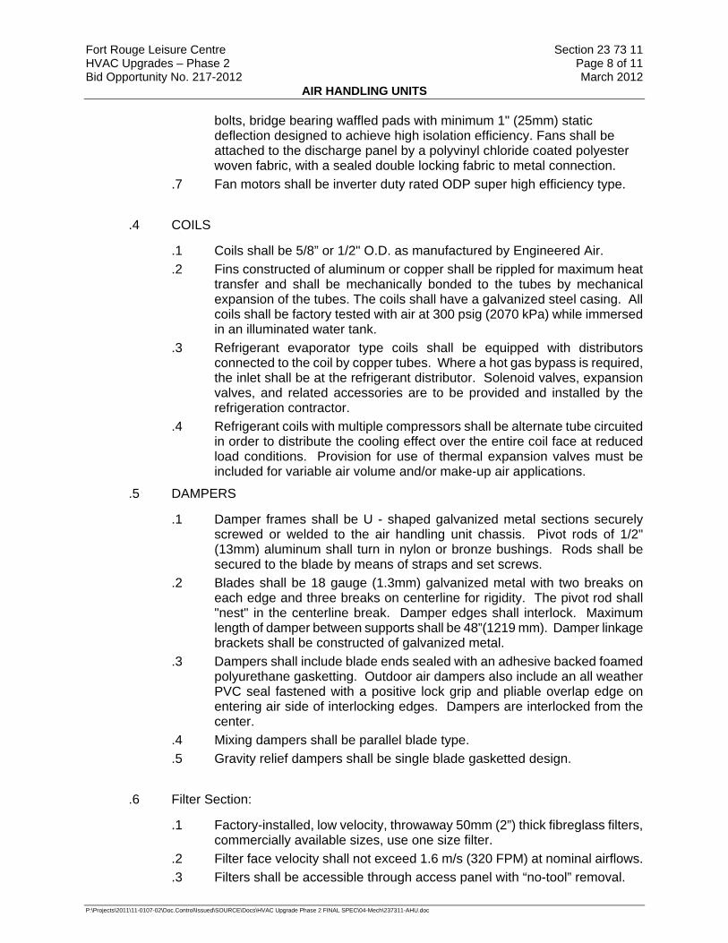
Fort Rouge Leisure Centre Section 23 73 11 HVAC Upgrades – Phase 2 Page 8 of 11 Bid Opportunity No. 217-2012 March 2012
AIR HANDLING UNITS
P:\Projects\2011\11-0107-02\Doc.Control\Issued\SOURCE\Docs\HVAC Upgrade Phase 2 FINAL SPEC\04-Mech\237311-AHU.doc
bolts, bridge bearing waffled pads with minimum 1" (25mm) static deflection designed to achieve high isolation efficiency. Fans shall be attached to the discharge panel by a polyvinyl chloride coated polyester woven fabric, with a sealed double locking fabric to metal connection.
.7 Fan motors shall be inverter duty rated ODP super high efficiency type.
.4 COILS
.1 Coils shall be 5/8” or 1/2" O.D. as manufactured by Engineered Air.
.2 Fins constructed of aluminum or copper shall be rippled for maximum heat transfer and shall be mechanically bonded to the tubes by mechanical expansion of the tubes. The coils shall have a galvanized steel casing. All coils shall be factory tested with air at 300 psig (2070 kPa) while immersed in an illuminated water tank.
.3 Refrigerant evaporator type coils shall be equipped with distributors connected to the coil by copper tubes. Where a hot gas bypass is required, the inlet shall be at the refrigerant distributor. Solenoid valves, expansion valves, and related accessories are to be provided and installed by the refrigeration contractor.
.4 Refrigerant coils with multiple compressors shall be alternate tube circuited in order to distribute the cooling effect over the entire coil face at reduced load conditions. Provision for use of thermal expansion valves must be included for variable air volume and/or make-up air applications.
.5 DAMPERS
.1 Damper frames shall be U - shaped galvanized metal sections securely screwed or welded to the air handling unit chassis. Pivot rods of 1/2" (13mm) aluminum shall turn in nylon or bronze bushings. Rods shall be secured to the blade by means of straps and set screws.
.2 Blades shall be 18 gauge (1.3mm) galvanized metal with two breaks on each edge and three breaks on centerline for rigidity. The pivot rod shall "nest" in the centerline break. Damper edges shall interlock. Maximum length of damper between supports shall be 48”(1219 mm). Damper linkage brackets shall be constructed of galvanized metal.
.3 Dampers shall include blade ends sealed with an adhesive backed foamed polyurethane gasketting. Outdoor air dampers also include an all weather PVC seal fastened with a positive lock grip and pliable overlap edge on entering air side of interlocking edges. Dampers are interlocked from the center.
.4 Mixing dampers shall be parallel blade type.
.5 Gravity relief dampers shall be single blade gasketted design.
.6 Filter Section:
.1 Factory-installed, low velocity, throwaway 50mm (2”) thick fibreglass filters, commercially available sizes, use one size filter.
.2 Filter face velocity shall not exceed 1.6 m/s (320 FPM) at nominal airflows.
.3 Filters shall be accessible through access panel with “no-tool” removal.

Fort Rouge Leisure Centre Section 23 73 11 HVAC Upgrades – Phase 2 Page 9 of 11 Bid Opportunity No. 217-2012 March 2012
AIR HANDLING UNITS
P:\Projects\2011\11-0107-02\Doc.Control\Issued\SOURCE\Docs\HVAC Upgrade Phase 2 FINAL SPEC\04-Mech\237311-AHU.doc
.7 MECHANICAL COOLING
.1 Compressors shall be hermetic type, 3600 RPM, set on resilient neoprene
mounts and complete with line voltage break internal overload protection, internal pressure relief valve and crankcase heater.
.2 Air Cooled Condenser
.1 Condenser coils shall be copper tube type, mechanically expanded
into aluminum fins. Coils shall be factory tested with air at 300 psig (2070 kPa) while immersed in an illuminated water tank.
.2 Condenser fans shall be direct driven propeller type arranged for vertical draw through airflow. Motors shall be weather resistant type, with integral overload protection and designed for vertical shaft condenser fan applications. Fan and motor assemblies shall be mounted on a formed orifice plate for optimum efficiency with minimum noise level.
.3 Condenser to form an integral part of the unit.
.3 Packaged Air Conditioning Units
.1 Packaged units shall be CETL, ETLUS approved and operate down to 50°F(10°C) as standard. Where applicable, multiple refrigeration circuits shall be separate from each other. Refrigeration circuits shall be complete with liquid line filter-driers, and service ports fitted with Schraeder fittings. Units with over 6 Ton hermetic compressors shall also incorporate load compensated thermal expansion valves with external equalizers and combination sight glass moisture indicators. The complete piping system shall be purged and pressure tested with dry nitrogen, then tested again under vacuum. Each system shall be factory run and adjusted prior to shipment.
.2 Packaged units shall be supplied with R-410a refrigerant.
.3 Controls for hermetic compressor units shall include compressor and condenser fan motor contactors, supply fan contactors and overload protection, control circuit transformer, cooling relays, ambient compressor lockout, automatic reset low pressure controls, and manual reset high pressure controls on compressors over 6 tons. Head pressure actuated fan cycling control shall be provided on all multiple condenser fan units.
.4 Provide hot gas bypass on the lead compressor to maintain adequate suction pressure in the event of low loads.
.5 Compressors shall be located on the side of the unit in a service enclosure complete with hinged access doors.

Fort Rouge Leisure Centre Section 23 73 11 HVAC Upgrades – Phase 2 Page 10 of 11 Bid Opportunity No. 217-2012 March 2012
AIR HANDLING UNITS
P:\Projects\2011\11-0107-02\Doc.Control\Issued\SOURCE\Docs\HVAC Upgrade Phase 2 FINAL SPEC\04-Mech\237311-AHU.doc
.8 FACTORY/FIELD SUPPLIED CONTROLS
.1 Provide a system of motor control include terminal blocks for wiring of
remote VFDs. VFD’s supplied by division 26. VFDs shall be powered from the air handling unit (wiring to and from the VFD to the air handling unit is by division 26). VFDs are controlled by section 230933.
.2 Fire alarm circuits shall be powered from a relay in unit circuitry.
.3 Automatic controls shall be housed in a control panel mounted in or on the air handling unit, which will meet that standard of the specific installation.
.4 Modulating damper operator shall be installed by the manufacturer and controlled by section 230933.
.5 Three stages of DX cooling controlled through the DDC system by section 230933.
.9 Electrical:
.1 Unit voltage shall be 575V/3Ph/60Hz single point connection.
.10 Air Handling Unit Schedule:
AIR HANDLING UNIT SCHEDULE
FAN NO. AHU-4 SERVICE
MANUFACTURER Engineered Air MODEL FWEA163/C/O
L/S (CFM): 2832 (6,000) ESP (“WC): 1
MOTOR (HP): 7.5 BLOWER: 15/15
SUPPLY
BLOWER SPEED (RPM): 1121
L/S (CFM): 2832 (6,000) ESP (“WC): 0.5
MOTOR (HP): 5 BLOWER: 15/15
RETURN
BLOWER SPEED (RPM): 837
EAT (DB/WB): 26.6/19.4°C (80/67°F) LAT (DB/WB): 13.8/13.6°C (56.9/56.5°F)
Total Capacity: 61.44 kW (209.7 MBH)
COOLING
SUCTION: 10.5°C (51°F) EAT (DB): 12.7°C (55°F) HEATING LAT (DB): 29.4°C (85°F)
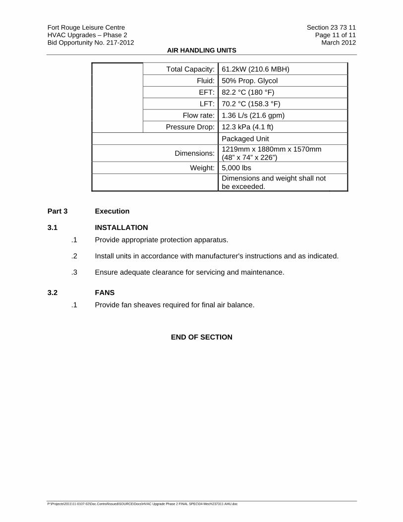
Fort Rouge Leisure Centre Section 23 73 11 HVAC Upgrades – Phase 2 Page 11 of 11 Bid Opportunity No. 217-2012 March 2012
AIR HANDLING UNITS
P:\Projects\2011\11-0107-02\Doc.Control\Issued\SOURCE\Docs\HVAC Upgrade Phase 2 FINAL SPEC\04-Mech\237311-AHU.doc
Total Capacity: 61.2kW (210.6 MBH) Fluid: 50% Prop. Glycol EFT: 82.2 °C (180 °F) LFT: 70.2 °C (158.3 °F)
Flow rate: 1.36 L/s (21.6 gpm) Pressure Drop: 12.3 kPa (4.1 ft)
Packaged Unit
Dimensions: 1219mm x 1880mm x 1570mm (48” x 74” x 226”)
Weight: 5,000 lbs Dimensions and weight shall not be exceeded.
Part 3 Execution
3.1 INSTALLATION .1 Provide appropriate protection apparatus.
.2 Install units in accordance with manufacturer's instructions and as indicated.
.3 Ensure adequate clearance for servicing and maintenance.
3.2 FANS .1 Provide fan sheaves required for final air balance.
END OF SECTION
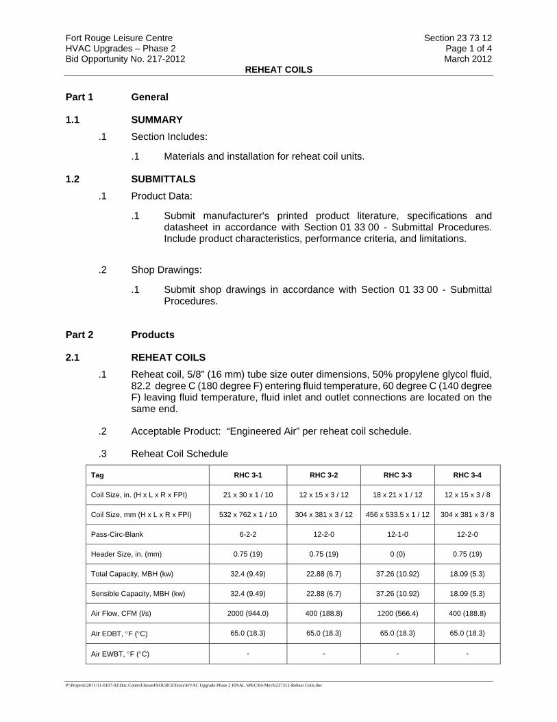
Fort Rouge Leisure Centre Section 23 73 12 HVAC Upgrades – Phase 2 Page 1 of 4 Bid Opportunity No. 217-2012 March 2012
REHEAT COILS
P:\Projects\2011\11-0107-02\Doc.Control\Issued\SOURCE\Docs\HVAC Upgrade Phase 2 FINAL SPEC\04-Mech\237312-Reheat Coils.doc
Part 1 General
1.1 SUMMARY .1 Section Includes:
.1 Materials and installation for reheat coil units.
1.2 SUBMITTALS .1 Product Data:
.1 Submit manufacturer's printed product literature, specifications and datasheet in accordance with Section 01 33 00 - Submittal Procedures. Include product characteristics, performance criteria, and limitations.
.2 Shop Drawings:
.1 Submit shop drawings in accordance with Section 01 33 00 - Submittal Procedures.
Part 2 Products
2.1 REHEAT COILS .1 Reheat coil, 5/8” (16 mm) tube size outer dimensions, 50% propylene glycol fluid,
82.2 degree C (180 degree F) entering fluid temperature, 60 degree C (140 degree F) leaving fluid temperature, fluid inlet and outlet connections are located on the same end.
.2 Acceptable Product: “Engineered Air” per reheat coil schedule.
.3 Reheat Coil Schedule
Tag RHC 3-1 RHC 3-2 RHC 3-3 RHC 3-4
Coil Size, in. (H x L x R x FPI) 21 x 30 x 1 / 10 12 x 15 x 3 / 12 18 x 21 x 1 / 12 12 x 15 x 3 / 8
Coil Size, mm (H x L x R x FPI) 532 x 762 x 1 / 10 304 x 381 x 3 / 12 456 x 533.5 x 1 / 12 304 x 381 x 3 / 8
Pass-Circ-Blank 6-2-2 12-2-0 12-1-0 12-2-0
Header Size, in. (mm) 0.75 (19) 0.75 (19) 0 (0) 0.75 (19)
Total Capacity, MBH (kw) 32.4 (9.49) 22.88 (6.7) 37.26 (10.92) 18.09 (5.3)
Sensible Capacity, MBH (kw) 32.4 (9.49) 22.88 (6.7) 37.26 (10.92) 18.09 (5.3)
Air Flow, CFM (l/s) 2000 (944.0) 400 (188.8) 1200 (566.4) 400 (188.8)
Air EDBT, °F (°C) 65.0 (18.3) 65.0 (18.3) 65.0 (18.3) 65.0 (18.3)
Air EWBT, °F (°C) - - - -

Fort Rouge Leisure Centre Section 23 73 12 HVAC Upgrades – Phase 2 Page 2 of 4 Bid Opportunity No. 217-2012 March 2012
REHEAT COILS
P:\Projects\2011\11-0107-02\Doc.Control\Issued\SOURCE\Docs\HVAC Upgrade Phase 2 FINAL SPEC\04-Mech\237312-Reheat Coils.doc
Air LDBT, °F (°C) 80.0 (26.7) 118.0 (47.8) 93.8 (34.3) 106.9 (41.6)
Air LWBT, °F (°C) - - - -
Leaving Coil Velocity, AFPM (m/s) 478 (2.43) 358 (1.82) 490 (2.49) 351 (1.79)
Coil Pressure Drop, in.wc. (Pa) 0.09 (23.2) 0.18 (45.7) 0.11 (26.4) 0.14 (34.0)
Entering Temperature, °F (°C) 180.0 (82.2) 180.0 (82.2) 180.0 (82.2) 180.0 (82.2)
Leaving Temperature, °F (°C) 140.0 (60.0) 140.8 (60.5) 140.5 (60.3) 139.8 (59.9)
Flow Rate, GPM (l/s) 1.8 (0.114) 1.3 (0.082) 2.1 (0.132) 1.0 (0.063)
Tube Velocity, FPS (m/s) 1.0 (0.30) 0.7 (0.22) 2.3 (0.70) 0.5 (0.17)
Pressure Drop, ft.wc. (kPa) 0.8 (2.2) 0.7 (2.0) 1.6 (4.8) 0.6 (1.8)
Tag RHC 3-5 RHC 3-6 RHC 3-7 RHC 3-8
Coil Size, in. (H x L x R x FPI) 12 x 22 x 1 / 12 9 x 15 x 2 / 8 18 x 25 x 2 / 10 12 x 15 x 3 / 12
Coil Size, mm (H x L x R x FPI) 304 x 558.75 x 1 / 12 228 x 381 x 2 / 8 456 x 635 x 2 / 10 304 x 381 x 3 / 12
Pass-Circ-Blank 8-1-0 10-1-2 8-3-0 12-2-0
Header Size, in. (mm) 0.75 (19) 0.75 (19) 0.75 (19) 0.75 (19)
Total Capacity, MBH (kw) 18.23 (5.34) 8.84 (2.59) 60.75 (17.8) 22.88 (6.7)
Sensible Capacity, MBH (kw) 18.23 (5.34) 8.84 (2.59) 60.75 (17.8) 22.88 (6.7)
Air Flow, CFM (l/s) 800 (377.6) 400 (188.8) 1600 (755.2) 400 (188.8)
Air EDBT, °F (°C) 65.0 (18.3) 65.0 (18.3) 65.0 (18.3) 65.0 (18.3)
Air EWBT, °F (°C) - - - -
Air LDBT, °F (°C) 86.1 (30.1) 85.5 (29.7) 100.2 (37.9) 118.0 (47.8)
Air LWBT, °F (°C) - - - -
Leaving Coil Velocity, AFPM (m/s) 462 (2.35) 451 (2.29) 556 (2.82) 358 (1.82)
Coil Pressure Drop, in.wc. (Pa) 0.10 (24.3) 0.14 (35.0) 0.23 (56.6) 0.18 (45.7)
Entering Temperature, °F (°C) 180.0 (82.2) 180.0 (82.2) 180.0 (82.2) 180.0 (82.2)
Leaving Temperature, °F (°C) 139.5 (59.7) 140.7 (60.4) 141.4 (60.8) 140.8 (60.5)
Flow Rate, GPM (l/s) 1.0 (0.063) 0.5 (0.032) 3.5 (0.221) 1.3 (0.082)
Tube Velocity, FPS (m/s) 1.1 (0.33) 0.5 (0.17) 1.3 (0.39) 0.7 (0.22)
Pressure Drop, ft.wc. (kPa) 0.8 (2.2) 0.6 (1.7) 1.1 (3.3) 0.7 (2.0)

Fort Rouge Leisure Centre Section 23 73 12 HVAC Upgrades – Phase 2 Page 3 of 4 Bid Opportunity No. 217-2012 March 2012
REHEAT COILS
P:\Projects\2011\11-0107-02\Doc.Control\Issued\SOURCE\Docs\HVAC Upgrade Phase 2 FINAL SPEC\04-Mech\237312-Reheat Coils.doc
Tag RHC 4-1 RHC 4-2 RHC 4-3 RHC 4-4
Coil Size, in. (H x L x R x FPI) 10.5 x 22 x 2 / 12 18 x 25 x 2 / 8 22.5 x 30 x 2 / 12 18 x 21 x 2 / 12
Coil Size, mm (H x L x R x FPI) 266 x 558.75 x 2 / 12 456 x 635 x 2 / 8 570 x 762 x 2 / 12 456 x 533.5 x 2 / 12
Pass-Circ-Blank 10-1-4 8-3-0 6-5-0 8-3-0
Header Size, in. (mm) 0.75 (19) 0.75 (19) 0.75 (19) 0.75 (19)
Total Capacity, MBH (kw) 28.89 (8.46) 46.71 (13.69) 59.06 (17.31) 43.94 (12.88)
Sensible Capacity, MBH (kw) 28.89 (8.46) 46.71 (13.69) 59.06 (17.31) 43.94 (12.88)
Air Flow, CFM (l/s) 800 (377.6) 1600 (755.2) 2000 (944.0) 1200 (566.4)
Air EDBT, °F (°C) 65.0 (18.3) 65.0 (18.3) 65.0 (18.3) 65.0 (18.3)
Air EWBT, °F (°C) - - - -
Air LDBT, °F (°C) 98.4 (36.9) 92.0 (33.4) 92.3 (33.5) 98.9 (37.2)
Air LWBT, °F (°C) - - - -
Leaving Coil Velocity, AFPM (m/s)
540 (2.74) 548 (2.78) 457 (2.32) 495 (2.51)
Coil Pressure Drop, in.wc. (Pa) 0.25 (61.0) 0.19 (47.5) 0.19 (46.9) 0.21 (52.8)
Entering Temperature, °F (°C) 180.0 (82.2) 180.0 (82.2) 180.0 (82.2) 180.0 (82.2)
Leaving Temperature, °F (°C) 139.8 (59.9) 140.0 (60.0) 138.9 (59.4) 140.9 (60.5)
Flow Rate, GPM (l/s) 1.6 (0.101) 2.6 (0.164) 3.2 (0.202) 2.5 (0.158)
Tube Velocity, FPS (m/s) 1.7 (0.53) 0.9 (0.29) 0.7 (0.21) 0.9 (0.28)
Pressure Drop, ft.wc. (kPa) 1.4 (4.2) 0.8 (2.4) 0.8 (2.3) 0.8 (2.3)
Tag RHC 4-5
Coil Size, in. (H x L x R x FPI) 9 x 15 x 2 / 8
Coil Size, mm (H x L x R x FPI) 228 x 381 x 2 / 8
Pass-Circ-Blank 10-1-2
Header Size, in. (mm) 0.75 (19)
Total Capacity, MBH (kw) 8.84 (2.59)
Sensible Capacity, MBH (kw) 8.84 (2.59)
Air Flow, CFM (l/s) 400 (188.8)

Fort Rouge Leisure Centre Section 23 73 12 HVAC Upgrades – Phase 2 Page 4 of 4 Bid Opportunity No. 217-2012 March 2012
REHEAT COILS
P:\Projects\2011\11-0107-02\Doc.Control\Issued\SOURCE\Docs\HVAC Upgrade Phase 2 FINAL SPEC\04-Mech\237312-Reheat Coils.doc
Air EDBT, °F (°C) 65.0 (18.3)
Air EWBT, °F (°C) -
Air LDBT, °F (°C) 85.5 (29.7)
Air LWBT, °F (°C) -
Leaving Coil Velocity, AFPM (m/s)
451 (2.29)
Coil Pressure Drop, in.wc. (Pa) 0.14 (35.0)
Entering Temperature, °F (°C) 180.0 (82.2)
Leaving Temperature, °F (°C) 140.7 (60.4)
Flow Rate, GPM (l/s) 0.5 (0.032)
Tube Velocity, FPS (m/s) 0.5 (0.17)
Pressure Drop, ft.wc. (kPa) 0.6 (1.7)
Part 3 Execution
3.1 MANUFACTURER'S INSTRUCTIONS .1 Compliance: comply with manufacturer's written recommendations or
specifications, including product technical bulletins, handling, storage and installation instructions, and datasheet.
END OF SECTION

Fort Rouge Leisure Centre Section 23 82 39 HVAC Upgrades – Phase 2 Page 1 of 3 Bid Opportunity No. 217-2012 March 2012
UNIT HEATERS
P:\Projects\2011\11-0107-02\Doc.Control\Issued\SOURCE\Docs\HVAC Upgrade Phase 2 FINAL SPEC\04-Mech\238239-UnitHeaters.doc
Part 1 General
1.1 RELATED SECTIONS .1 Section 01 33 00 - Submittal Procedures.
1.2 PRODUCT DATA .1 Submit product data in accordance with Section 01 33 00 - Submittal
Procedures.
.2 Submit product data sheets for unit heaters. Include:
.1 Product characteristics.
.2 Performance criteria.
.3 Mounting methods.
.4 Physical size.
.5 kW rating, voltage, phase.
.6 Cabinet material thicknesses.
.7 Limitations.
.8 Colour and finish.
.3 Manufacturer's Instructions: Provide to indicate special handling criteria, installation sequence, and cleaning procedures.
1.3 SHOP DRAWINGS .1 Submit shop drawings in accordance with Section 01 33 00 - Submittal
Procedures.
.2 Indicate:
.1 Equipment, capacity and piping connections.
.2 Dimensions, internal and external construction details, recommended method of installation with proposed [structural steel] support, sizes and location of mounting bolt holes.
1.4 CLOSEOUT SUBMITTALS .1 Provide operation and maintenance data for unit heaters for incorporation into
manual specified in Section 01 78 00 - Closeout Submittals.
Part 2 Products
2.1 CABINET UNIT HEATERS .1 Cabinet: type surface, wall mount, integral stamped louvers air outlet and inlet,
18-gauge steel with 16 gauge front panels with rounded exposed corners and edges, removable panels, .
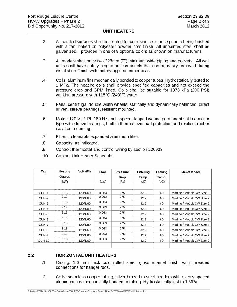
Fort Rouge Leisure Centre Section 23 82 39 HVAC Upgrades – Phase 2 Page 2 of 3 Bid Opportunity No. 217-2012 March 2012
UNIT HEATERS
P:\Projects\2011\11-0107-02\Doc.Control\Issued\SOURCE\Docs\HVAC Upgrade Phase 2 FINAL SPEC\04-Mech\238239-UnitHeaters.doc
.2 All painted surfaces shall be treated for corrosion resistance prior to being finished with a tan, baked on polyester powder coat finish. All unpainted steel shall be galvanized. provided in one of 8 optional colors as shown on manufacturer’s
.3 All models shall have two 228mm (9") minimum wide piping end pockets. All wall units shall have safety hinged access panels that can be easily removed during installation Finish with factory applied primer coat.
.4 Coils: aluminum fins mechanically bonded to copper tubes. Hydrostatically tested to 1 MPa. The heating coils shall provide specified capacities and not exceed the pressure drop and GPM listed. Coils shall be suitable for 1378 kPa (200 PSI) working pressure with 115°C (240°F) water.
.5 Fans: centrifugal double width wheels, statically and dynamically balanced, direct driven, sleeve bearings, resilient mounted.
.6 Motor: 120 V / 1 Ph / 60 Hz, multi-speed, tapped wound permanent split capacitor type with sleeve bearings, built-in thermal overload protection and resilient rubber isolation mounting.
.7 Filters: cleanable expanded aluminum filter.
.8 Capacity: as indicated.
.9 Control: thermostat and control wiring by section 230933
.10 Cabinet Unit Heater Schedule:
Tag Heating Volts/Ph Flow Pressure Entering Leaving Make/ Model Output Drop Temp. Temp. (kW) (L/s) (Pa) (dC) (dC)
CUH-1 3.13 120/1/60 0.063 275 82.2 60 Modine / Model: CW Size 2
CUH-2 3.13 120/1/60 0.063 275 82.2 60 Modine / Model: CW Size 2
CUH-3 3.13 120/1/60 0.063 275 82.2 60 Modine / Model: CW Size 2
CUH-4 3.13 120/1/60 0.063 275 82.2 60 Modine / Model: CW Size 2
CUH-5 3.13 120/1/60 0.063 275 82.2 60 Modine / Model: CW Size 2
CUH-6 3.13 120/1/60 0.063 275 82.2 60 Modine / Model: CW Size 2
CUH-7 3.13 120/1/60 0.063 275 82.2 60 Modine / Model: CW Size 2
CUH-8 3.13 120/1/60 0.063 275 82.2 60 Modine / Model: CW Size 2
CUH-9 3.13 120/1/60 0.063 275 82.2 60 Modine / Model: CW Size 2
CUH-10 3.13 120/1/60 0.063 275 82.2 60 Modine / Model: CW Size 2
2.2 HORIZONTAL UNIT HEATERS .1 Casing: 1.6 mm thick cold rolled steel, gloss enamel finish, with threaded
connections for hanger rods.
.2 Coils: seamless copper tubing, silver brazed to steel headers with evenly spaced aluminum fins mechanically bonded to tubing. Hydrostatically test to 1 MPa.
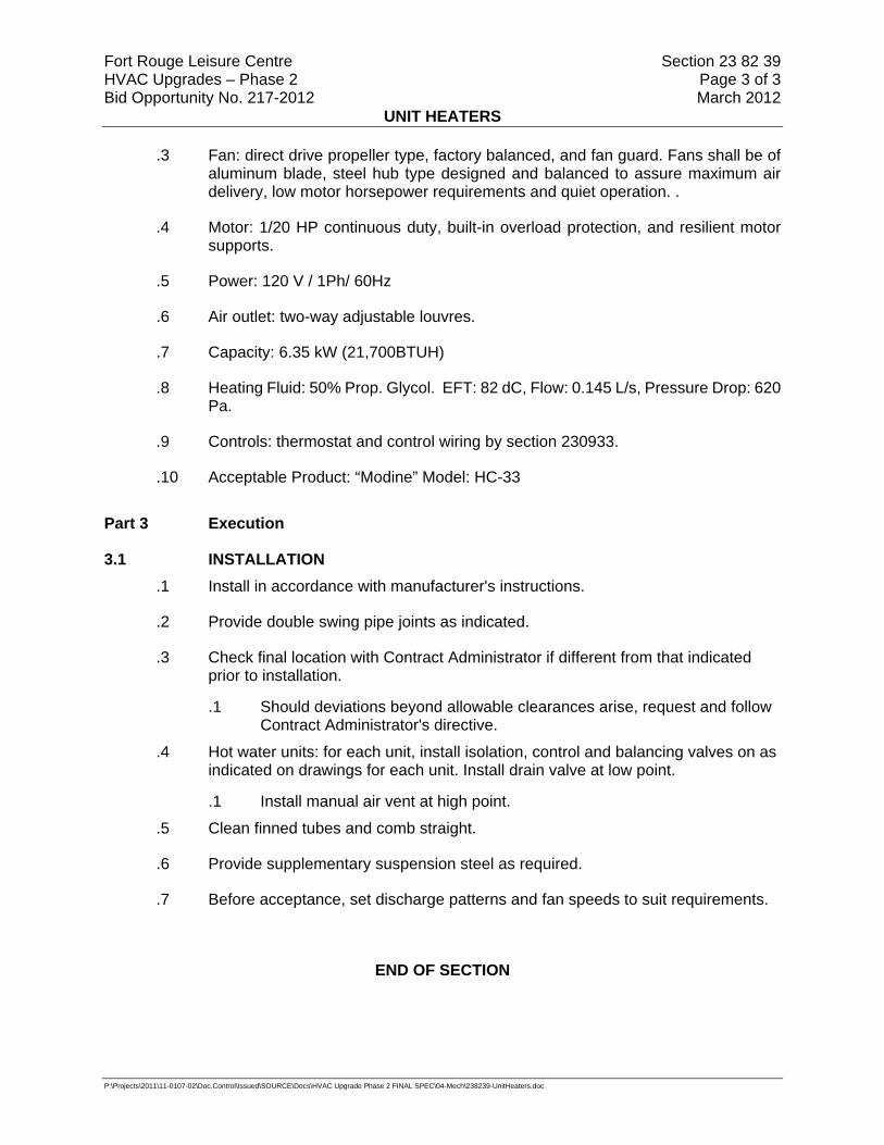
Fort Rouge Leisure Centre Section 23 82 39 HVAC Upgrades – Phase 2 Page 3 of 3 Bid Opportunity No. 217-2012 March 2012
UNIT HEATERS
P:\Projects\2011\11-0107-02\Doc.Control\Issued\SOURCE\Docs\HVAC Upgrade Phase 2 FINAL SPEC\04-Mech\238239-UnitHeaters.doc
.3 Fan: direct drive propeller type, factory balanced, and fan guard. Fans shall be of aluminum blade, steel hub type designed and balanced to assure maximum air delivery, low motor horsepower requirements and quiet operation. .
.4 Motor: 1/20 HP continuous duty, built-in overload protection, and resilient motor supports.
.5 Power: 120 V / 1Ph/ 60Hz
.6 Air outlet: two-way adjustable louvres.
.7 Capacity: 6.35 kW (21,700BTUH)
.8 Heating Fluid: 50% Prop. Glycol. EFT: 82 dC, Flow: 0.145 L/s, Pressure Drop: 620 Pa.
.9 Controls: thermostat and control wiring by section 230933.
.10 Acceptable Product: “Modine” Model: HC-33
Part 3 Execution
3.1 INSTALLATION .1 Install in accordance with manufacturer's instructions.
.2 Provide double swing pipe joints as indicated.
.3 Check final location with Contract Administrator if different from that indicated prior to installation.
.1 Should deviations beyond allowable clearances arise, request and follow Contract Administrator's directive.
.4 Hot water units: for each unit, install isolation, control and balancing valves on as indicated on drawings for each unit. Install drain valve at low point.
.1 Install manual air vent at high point.
.5 Clean finned tubes and comb straight.
.6 Provide supplementary suspension steel as required.
.7 Before acceptance, set discharge patterns and fan speeds to suit requirements.
END OF SECTION

Fort Rouge Leisure Centre Section 26 05 01 HVAC Upgrades – Phase 2 Page 1 of 8 Bid Opportunity No.217-2012 March 2012
COMMON WORK RESULTS - ELECTRICAL
P:\Projects\2011\11-0107-02\Doc.Control\Issued\SOURCE\Docs\HVAC Upgrade Phase 2 FINAL SPEC\05-Elec\260501.doc
Part 1 General
1.1 REFERENCES .1 Canadian Standards Association (CSA International)
.1 CSA C22.1-06, Canadian Electrical Code, Part 1 (20th Edition), Safety Standard for Electrical Installations.
.2 CSA C22.2.
.3 CAN/CSA-C22.3 No. 1, Overhead Systems.
.4 CAN3-C235-83(R2000), Preferred Voltage Levels for AC Systems, 0 to 50,000 V.
.2 Electrical and Electronic Manufacturer's Association of Canada (EEMAC)
.1 EEMAC 2Y-1-1958, Light Gray Colour for Indoor Switch Gear.
.3 Institute of Electrical and Electronics (IEEE)/National Electrical Safety Code Product Line (NESC)
.1 IEEE SP1122-2000, The Authoritative Dictionary of IEEE Standards Terms, 7th Edition.
1.2 DEFINITIONS .1 Electrical and electronic terms: unless otherwise specified or indicated, terms used
in these specifications, and on drawings, are those defined by IEEE SP1122.
1.3 DESIGN REQUIREMENTS .1 Operating voltages: to CAN3-C235.
.2 Motors, electric heating, control and distribution devices and equipment to operate satisfactorily at 60 Hz within normal operating limits established by above standard.
.1 Equipment to operate in extreme operating conditions established in above standard without damage to equipment.
.3 Language operating requirements: provide identification nameplates and labels for control items in English.
.4 The contractor shall be required to obtain a complete FAS VI report for the FAS including the FAS Sprinkler system. A copy of these reports shall be left on site at the main FAS panel as well as a complete FAS device list (with addresses). Soft copies of these reports are required. As built drawings of a floor plan with all of the FAS devices, indicating approx. device location and addressable address shall be provided. The contractor shall supply as built drawings of all of the FAS network loops. The contractor shall supply as built drawings of sprinkler system showing approx. location of all sprinkler devices and zoning.
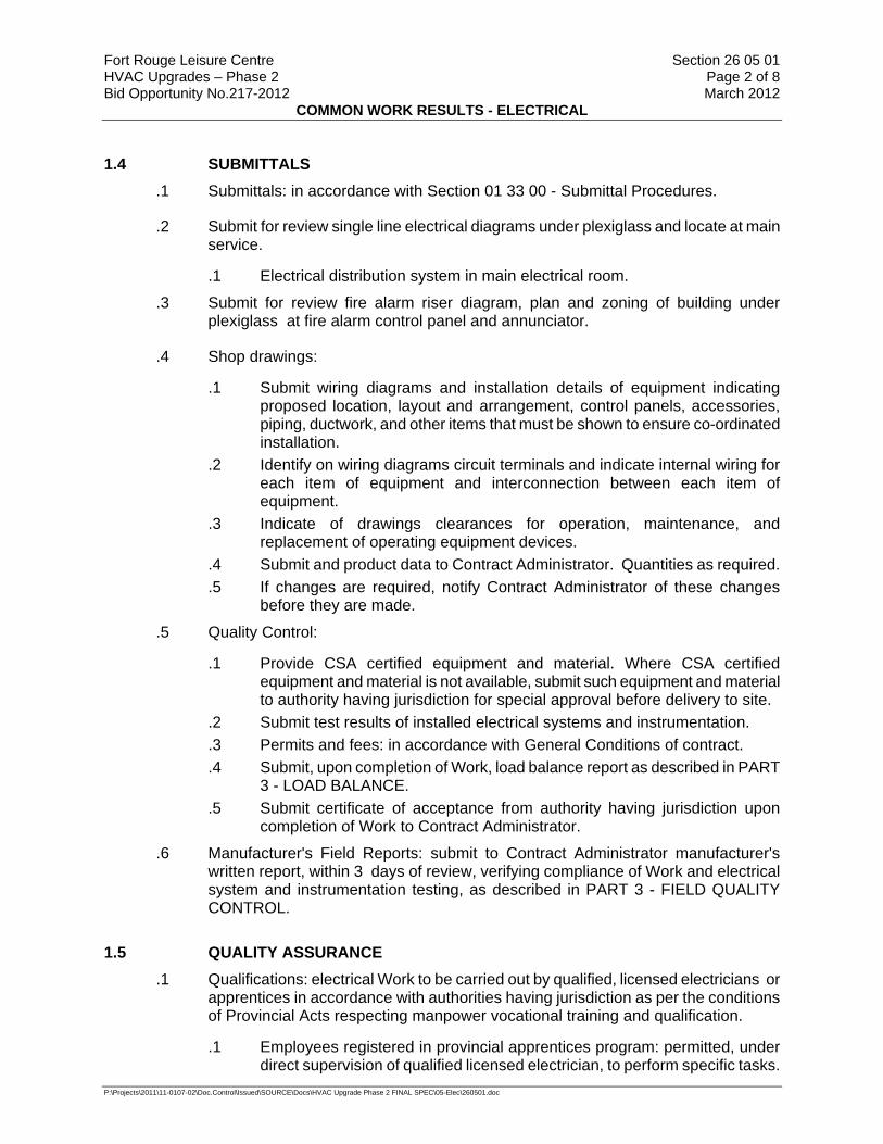
Fort Rouge Leisure Centre Section 26 05 01 HVAC Upgrades – Phase 2 Page 2 of 8 Bid Opportunity No.217-2012 March 2012
COMMON WORK RESULTS - ELECTRICAL
P:\Projects\2011\11-0107-02\Doc.Control\Issued\SOURCE\Docs\HVAC Upgrade Phase 2 FINAL SPEC\05-Elec\260501.doc
1.4 SUBMITTALS .1 Submittals: in accordance with Section 01 33 00 - Submittal Procedures.
.2 Submit for review single line electrical diagrams under plexiglass and locate at main service.
.1 Electrical distribution system in main electrical room.
.3 Submit for review fire alarm riser diagram, plan and zoning of building under plexiglass at fire alarm control panel and annunciator.
.4 Shop drawings:
.1 Submit wiring diagrams and installation details of equipment indicating proposed location, layout and arrangement, control panels, accessories, piping, ductwork, and other items that must be shown to ensure co-ordinated installation.
.2 Identify on wiring diagrams circuit terminals and indicate internal wiring for each item of equipment and interconnection between each item of equipment.
.3 Indicate of drawings clearances for operation, maintenance, and replacement of operating equipment devices.
.4 Submit and product data to Contract Administrator. Quantities as required.
.5 If changes are required, notify Contract Administrator of these changes before they are made.
.5 Quality Control:
.1 Provide CSA certified equipment and material. Where CSA certified equipment and material is not available, submit such equipment and material to authority having jurisdiction for special approval before delivery to site.
.2 Submit test results of installed electrical systems and instrumentation.
.3 Permits and fees: in accordance with General Conditions of contract.
.4 Submit, upon completion of Work, load balance report as described in PART 3 - LOAD BALANCE.
.5 Submit certificate of acceptance from authority having jurisdiction upon completion of Work to Contract Administrator.
.6 Manufacturer's Field Reports: submit to Contract Administrator manufacturer's written report, within 3 days of review, verifying compliance of Work and electrical system and instrumentation testing, as described in PART 3 - FIELD QUALITY CONTROL.
1.5 QUALITY ASSURANCE .1 Qualifications: electrical Work to be carried out by qualified, licensed electricians or
apprentices in accordance with authorities having jurisdiction as per the conditions of Provincial Acts respecting manpower vocational training and qualification.
.1 Employees registered in provincial apprentices program: permitted, under direct supervision of qualified licensed electrician, to perform specific tasks.

Fort Rouge Leisure Centre Section 26 05 01 HVAC Upgrades – Phase 2 Page 3 of 8 Bid Opportunity No.217-2012 March 2012
COMMON WORK RESULTS - ELECTRICAL
P:\Projects\2011\11-0107-02\Doc.Control\Issued\SOURCE\Docs\HVAC Upgrade Phase 2 FINAL SPEC\05-Elec\260501.doc
.2 Permitted activities: determined based on training level attained and demonstration of ability to perform specific duties.
.2 Site Meetings:
.1 In accordance with Construction Progress Schedule - Bar (GANTT) Charts.
1.6 DELIVERY, STORAGE AND HANDLING .1 Construction/Demolition Waste Management and Disposal: separate waste
materials for reuse and recycling.
1.7 SYSTEM STARTUP .1 Instruct Operating Personnel in operation, care and maintenance of systems,
system equipment and components.
.2 Arrange and pay for services of manufacturer's factory service engineer to supervise start-up of installation, check, adjust, balance and calibrate components and instruct operating personnel.
.3 Provide these services for such period, and for as many visits as necessary to put equipment in operation, and ensure that operating personnel are conversant will aspects of its care and operation.
1.8 OPERATING INSTRUCTIONS .1 Provide for each system and principal item of equipment as specified in technical
sections for use by operation and maintenance personnel.
.2 Operating instructions to include following:
.1 Wiring diagrams, control diagrams, and control sequence for each principal system and item of equipment.
.2 Start up, proper adjustment, operating, lubrication, and shutdown procedures.
.3 Safety precautions.
.4 Procedures to be followed in event of equipment failure.
.5 Other items of instruction as recommended by manufacturer of each system or item of equipment.
.3 Print or engrave operating instructions and frame under glass or in approved laminated plastic.
.4 Post instructions where directed.
.5 For operating instructions exposed to weather, provide weather-resistant materials or weatherproof enclosures.
.6 Ensure operating instructions will not fade when exposed to sunlight and are secured to prevent easy removal or peeling.
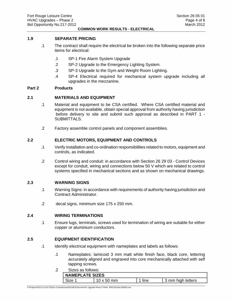
Fort Rouge Leisure Centre Section 26 05 01 HVAC Upgrades – Phase 2 Page 4 of 8 Bid Opportunity No.217-2012 March 2012
COMMON WORK RESULTS - ELECTRICAL
P:\Projects\2011\11-0107-02\Doc.Control\Issued\SOURCE\Docs\HVAC Upgrade Phase 2 FINAL SPEC\05-Elec\260501.doc
1.9 SEPARATE PRICING .1 The contract shall require the electrical be broken into the following separate price
items for electrical:
.1 SP-1 Fire Alarm System Upgrade
.2 SP-2 Upgrade to the Emergency Lighting System.
.3 SP-3 Upgrade to the Gym and Weight Room Lighting.
.4 SP-4 Electrical required for mechanical system upgrade including all upgrades in the mezzanine.
Part 2 Products
2.1 MATERIALS AND EQUIPMENT .1 Material and equipment to be CSA certified. Where CSA certified material and
equipment is not available, obtain special approval from authority having jurisdiction before delivery to site and submit such approval as described in PART 1 - SUBMITTALS.
.2 Factory assemble control panels and component assemblies.
2.2 ELECTRIC MOTORS, EQUIPMENT AND CONTROLS .1 Verify installation and co-ordination responsibilities related to motors, equipment and
controls, as indicated.
.2 Control wiring and conduit: in accordance with Section 26 29 03 - Control Devices except for conduit, wiring and connections below 50 V which are related to control systems specified in mechanical sections and as shown on mechanical drawings.
2.3 WARNING SIGNS .1 Warning Signs: in accordance with requirements of authority having jurisdiction and
Contract Administrator.
.2 decal signs, minimum size 175 x 250 mm.
2.4 WIRING TERMINATIONS .1 Ensure lugs, terminals, screws used for termination of wiring are suitable for either
copper or aluminium conductors.
2.5 EQUIPMENT IDENTIFICATION .1 Identify electrical equipment with nameplates and labels as follows:
.1 Nameplates: lamicoid 3 mm matt white finish face, black core, lettering accurately aligned and engraved into core mechanically attached with self tapping screws.
.2 Sizes as follows: NAMEPLATE SIZES Size 1 10 x 50 mm 1 line 3 mm high letters

Fort Rouge Leisure Centre Section 26 05 01 HVAC Upgrades – Phase 2 Page 5 of 8 Bid Opportunity No.217-2012 March 2012
COMMON WORK RESULTS - ELECTRICAL
P:\Projects\2011\11-0107-02\Doc.Control\Issued\SOURCE\Docs\HVAC Upgrade Phase 2 FINAL SPEC\05-Elec\260501.doc
NAMEPLATE SIZES Size 2 12 x 70 mm 1 line 5 mm high letters Size 3 12 x 70 mm 2 lines 3 mm high letters Size 4 20 x 90 mm 1 line 8 mm high letters Size 5 20 x 90 mm 2 lines 5 mm high letters Size 6 25 x 100 mm 1 line 12 mm high letters Size 7 25 x 100 mm 2 lines 6 mm high letters
.2 Labels: embossed plastic labels with 6mm high letters unless specified otherwise.
.3 Wording on nameplates and labels to be approved by Contract Administrator prior to manufacture.
.4 Allow for minimum of twenty-five (25) letters per nameplate and label.
.5 Nameplates for terminal cabinets and junction boxes to indicate system and/or voltage characteristics.
.6 Disconnects, starters and contactors: indicate equipment being controlled and voltage.
.7 Terminal cabinets and pull boxes: indicate system and voltage.
.8 Transformers: indicate capacity, primary and secondary voltages.
2.6 WIRING IDENTIFICATION .1 Identify wiring with permanent indelible identifying markings, numbered, on both
ends of phase conductors of feeders and branch circuit wiring.
.2 Maintain phase sequence and colour coding throughout.
.3 Colour coding: to CSA C22.1.
.4 Use colour coded wires in communication cables, matched throughout system.
2.7 CONDUIT AND CABLE IDENTIFICATION .1 Colour code conduits, boxes and metallic sheathed cables.
.2 Code with plastic tape or paint at points where conduit or cable enters wall, ceiling, or floor, and at 5 m intervals.
.3 Colours: 25 mm wide prime colour and 15 mm wide auxiliary colour.
Prime Auxiliary up to 250 V Yellow up to 600 V Yellow Green up to 5 kV Yellow Blue up to 15 kV Yellow Red Telephone Green Other Communication Systems Green Blue
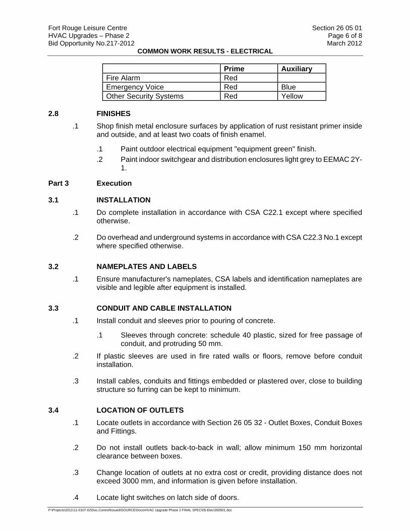
Fort Rouge Leisure Centre Section 26 05 01 HVAC Upgrades – Phase 2 Page 6 of 8 Bid Opportunity No.217-2012 March 2012
COMMON WORK RESULTS - ELECTRICAL
P:\Projects\2011\11-0107-02\Doc.Control\Issued\SOURCE\Docs\HVAC Upgrade Phase 2 FINAL SPEC\05-Elec\260501.doc
Prime Auxiliary Fire Alarm Red Emergency Voice Red Blue Other Security Systems Red Yellow
2.8 FINISHES .1 Shop finish metal enclosure surfaces by application of rust resistant primer inside
and outside, and at least two coats of finish enamel.
.1 Paint outdoor electrical equipment "equipment green" finish.
.2 Paint indoor switchgear and distribution enclosures light grey to EEMAC 2Y-1.
Part 3 Execution
3.1 INSTALLATION .1 Do complete installation in accordance with CSA C22.1 except where specified
otherwise.
.2 Do overhead and underground systems in accordance with CSA C22.3 No.1 except where specified otherwise.
3.2 NAMEPLATES AND LABELS .1 Ensure manufacturer's nameplates, CSA labels and identification nameplates are
visible and legible after equipment is installed.
3.3 CONDUIT AND CABLE INSTALLATION .1 Install conduit and sleeves prior to pouring of concrete.
.1 Sleeves through concrete: schedule 40 plastic, sized for free passage of conduit, and protruding 50 mm.
.2 If plastic sleeves are used in fire rated walls or floors, remove before conduit installation.
.3 Install cables, conduits and fittings embedded or plastered over, close to building structure so furring can be kept to minimum.
3.4 LOCATION OF OUTLETS .1 Locate outlets in accordance with Section 26 05 32 - Outlet Boxes, Conduit Boxes
and Fittings.
.2 Do not install outlets back-to-back in wall; allow minimum 150 mm horizontal clearance between boxes.
.3 Change location of outlets at no extra cost or credit, providing distance does not exceed 3000 mm, and information is given before installation.
.4 Locate light switches on latch side of doors.

Fort Rouge Leisure Centre Section 26 05 01 HVAC Upgrades – Phase 2 Page 7 of 8 Bid Opportunity No.217-2012 March 2012
COMMON WORK RESULTS - ELECTRICAL
P:\Projects\2011\11-0107-02\Doc.Control\Issued\SOURCE\Docs\HVAC Upgrade Phase 2 FINAL SPEC\05-Elec\260501.doc
.1 Locate disconnect devices in mechanical and elevator machine rooms on latch side of floor.
3.5 MOUNTING HEIGHTS .1 Mounting height of equipment is from finished floor to centreline of equipment unless
specified or indicated otherwise.
.2 If mounting height of equipment is not specified or indicated, verify before proceeding with installation. Install electrical equipment at following heights unless indicated otherwise.
.1 Local switches: 1200 mm.
.2 Wall receptacles: .1 General: 300 mm. .2 Above top of continuous baseboard heater: 200 mm. .3 Above top of counters or counter splash backs: 175 mm. .4 In mechanical rooms: 1400 mm.
.3 Panelboards: as required by Code or as indicated.
.4 Fire alarm stations: 1200 mm.
.5 Fire alarm bells/strobes: 2100 mm.
3.6 CO-ORDINATION OF PROTECTIVE DEVICES .1 Ensure circuit protective devices such as overcurrent trips, relays and fuses are
installed to required values and settings.Verify co-ordination with upstream devices.
3.7 FIELD QUALITY CONTROL .1 Load Balance:
.1 Measure phase current to panelboards with normal loads (lighting) operating at time of acceptance; adjust branch circuit connections as required to obtain best balance of current between phases and record changes.
.2 Measure phase voltages at loads and adjust transformer taps to within 2% of rated voltage of equipment.
.3 Provide upon completion of work, load balance report as directed in PART 1 - SUBMITTALS: phase and neutral currents on panelboards, dry-core transformers and motor control centres, operating under normal load, as well as hour and date on which each load was measured, and voltage at time of test.
.2 Conduct following tests:
.1 Power distribution system including phasing, voltage, grounding and load balancing.
.2 Circuits originating from branch distribution panels.
.3 Lighting and its control.
.4 Motors, heaters and associated control equipment including sequenced operation of systems where applicable.
.5 Systems: fire alarm system, Security System, PA system, communications.
.6 Insulation resistance testing:

Fort Rouge Leisure Centre Section 26 05 01 HVAC Upgrades – Phase 2 Page 8 of 8 Bid Opportunity No.217-2012 March 2012
COMMON WORK RESULTS - ELECTRICAL
P:\Projects\2011\11-0107-02\Doc.Control\Issued\SOURCE\Docs\HVAC Upgrade Phase 2 FINAL SPEC\05-Elec\260501.doc
.1 Megger circuits, feeders and equipment up to 350 V with a 500 V instrument.
.2 Megger 350-600 V circuits, feeders and equipment with a 1000 V instrument.
.3 Check resistance to ground before energizing.
.3 Carry out tests in presence of Departmental Representative.
.4 Provide instruments, meters, equipment and personnel required to conduct tests during and at conclusion of project.
.5 Manufacturer's Field Services:
.1 Obtain written report from manufacturer verifying compliance of Work, in handling, installing, applying, protecting and cleaning of product and submit Manufacturer's Field Reports as described in PART 1 - SUBMITTALS.
.2 Provide manufacturer's field services consisting of product use recommendations and periodic site visits for inspection of product installation in accordance with manufacturer's instructions.
.3 Schedule site visits, to review Work, as directed in PART 1 - QUALITY ASSURANCE.
3.8 CLEANING .1 Clean and touch up surfaces of shop-painted equipment scratched or marred during
shipment or installation, to match original paint.
.2 Clean and prime exposed non-galvanized hangers, racks and fastenings to prevent rusting.
END OF SECTION
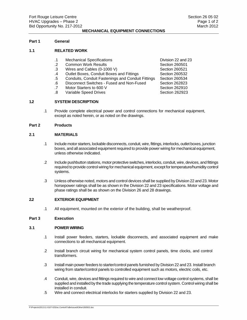
Fort Rouge Leisure Centre Section 26 05 02 HVAC Upgrades – Phase 2 Page 1 of 2 Bid Opportunity No. 217-2012 March 2012
MECHANICAL EQUIPMENT CONNECTIONS
P:\Projects\2011\11-0107-02\Doc.Control\ToBeIssued\Other\260502.doc
Part 1 General 1.1 RELATED WORK
.1 Mechanical Specifications Division 22 and 23
.2 Common Work Results Section 260501
.3 Wires and Cables (0-1000 V) Section 260521
.4 Outlet Boxes, Conduit Boxes and Fittings Section 260532
.5 Conduits, Conduit Fastenings and Conduit Fittings Section 260534
.6 Disconnect Switches - Fused and Non-Fused Section 262823
.7 Motor Starters to 600 V Section 262910
.8 Variable Speed Drives Section 262923 1.2 SYSTEM DESCRIPTION
.1 Provide complete electrical power and control connections for mechanical equipment, except as noted herein, or as noted on the drawings.
Part 2 Products 2.1 MATERIALS .1 Include motor starters, lockable disconnects, conduit, wire, fittings, interlocks, outlet boxes, junction
boxes, and all associated equipment required to provide power wiring for mechanical equipment, unless otherwise indicated.
.2 Include pushbutton stations, motor protective switches, interlocks, conduit, wire, devices, and fittings
required to provide control wiring for mechanical equipment, except for temperature/humidity control systems.
.3 Unless otherwise noted, motors and control devices shall be supplied by Division 22 and 23. Motor
horsepower ratings shall be as shown in the Division 22 and 23 specifications. Motor voltage and phase ratings shall be as shown on the Division 26 and 28 drawings.
2.2 EXTERIOR EQUIPMENT .1 All equipment, mounted on the exterior of the building, shall be weatherproof.
Part 3 Execution 3.1 POWER WIRING
.1 Install power feeders, starters, lockable disconnects, and associated equipment and make
connections to all mechanical equipment. .2 Install branch circuit wiring for mechanical system control panels, time clocks, and control
transformers. .3 Install main power feeders to starter/control panels furnished by Division 22 and 23. Install branch
wiring from starter/control panels to controlled equipment such as motors, electric coils, etc. .4 Conduit, wire, devices and fittings required to wire and connect low voltage control systems, shall be
supplied and installed by the trade supplying the temperature control system. Control wiring shall be installed in conduit.
.5 Wire and connect electrical interlocks for starters supplied by Division 22 and 23.

Fort Rouge Leisure Centre Section 26 05 02 HVAC Upgrades – Phase 2 Page 2 of 2 Bid Opportunity No. 217-2012 March 2012
MECHANICAL EQUIPMENT CONNECTIONS
P:\Projects\2011\11-0107-02\Doc.Control\ToBeIssued\Other\260502.doc
.6 Wire and connect hi-limit cutouts for remotely mounted electric heating coils provided by
Division 22 and 23. .7 Wire and connect thermistor control devices, built-in to large motors, to motor starters, as per
wiring diagrams provided by Division 22 and 23. 3.2 CONTROLS
.1 Install all electrical controls, except low voltage temperature controls, unless otherwise noted herein. Controls which have both electrical and mechanical connections shall be installed by the trade supplying the control.
.2 Wire and connect float switches, pressure switches, alternators, alarms, etc. for sump pumps,
domestic hot water re-circulating pumps, and booster pumps. .3 Conduit, wire, devices and fittings required to wire and connect low voltage controls, which are an
integral part of a packaged unit, shall be supplied by the trade supplying the packaged unit, unless otherwise indicated. Control wiring shall be installed in conduit.
.4 Wire and connect electrical interlocks for starters supplied by Division 22 and 23. .5 Wire and connect hi-limit cutouts for remotely mounted electric heating coils provided by
Division 22 and 23. .6 Wire and connect thermistor control devices, built-in to large motors, to motor starters, as per
wiring diagrams provided by Division 22 and 23. .7 Wire and Connect air Handling units to Fire Alarm Control Panel for Fan shutdown. Clearly
indicate on As-Built Drawings and Fire Alarm Graphical Drawing Unit wired to FACP for Fan shutdown.
3.3 CO-ORDINATION
.1 Refer to mechanical drawings for the exact location of motor control devices, and other mechanical equipment requiring an electrical connection.
.2 Obtain full information from Division 22 and 23, regarding wiring controls, overload heaters,
equipment ratings and over-current protection. Notify the Division 22 and 23, at once, if any information provided is incorrect or unsatisfactory.
.3 Refer to Division 22 and 23 specifications for any further electrical requirements. .4 Review both electrical and mechanical drawings and specifications and coordinate all controls
with Mechanical Subtrades through General Contractor. Report all discrepancies to contract administrator before close of bids. No additional money will be justified for assumptions made on any duplication of information.
END OF SECTION

Fort Rouge Leisure Centre Section 26 05 20 HVAC Upgrades – Phase 2 Page 1 of 1 Bid Opportunity No. 217-2012 March 2012
WIRE BOX CONNECTORS – 0 - 1000 V
P:\Projects\2011\11-0107-02\Doc.Control\Issued\SOURCE\Docs\HVAC Upgrade Phase 2 FINAL SPEC\05-Elec\260520.doc
Part 1 General
1.1 SECTION INCLUDES .1 Materials and installation for wire and box connectors.
1.2 REFERENCES .1 Canadian Standards Association (CSA International)
.1 CAN/CSA-C22.2No.18-98, Outlet Boxes, Conduit Boxes, Fittings and Associated Hardware.
.2 CSA C22.2No.65-93(R1999), Wire Connectors.
.2 Electrical and Electronic Manufacturers' Association of Canada (EEMAC)
.1 EEMAC 1Y-2, 1961 Bushing Stud Connectors and Aluminum Adapters (1200 Ampere Maximum Rating).
.3 National Electrical Manufacturers Association (NEMA)
Part 2 Products
2.1 MATERIALS .1 Pressure type wire connectors to: CSA C22.2 No.65, with current carrying parts of
copper or copper alloy sized to fit copper or aluminum conductors as required.
.2 Fixture type splicing connectors to: CSA C22.2 No.65, with current carrying parts of copper or copper alloy sized to fit copper conductors 10 AWG or less.
.3 Clamps or connectors for armoured cable, aluminum sheathed cable, flexible conduit, non-metallic sheathed cable as required to: CAN/CSA-C22.2 No.18.Execution
2.2 INSTALLATION .1 Remove insulation carefully from ends of conductors and:
.1 Apply coat of zinc joint compound on aluminum conductors prior to installation of connectors.
.2 Install mechanical pressure type connectors and tighten screws with appropriate compression tool recommended by manufacturer. Installation shall meet secureness tests in accordance with CSA C22.2No.65.
.3 Install fixture type connectors and tighten. Replace insulating cap.
.4 Install bushing stud connectors in accordance with NEMA.
END OF SECTION

Fort Rouge Leisure Centre Section 26 05 21 HVAC Upgrades – Phase 2 Page 1 of 3 Bid Opportunity No. 217-2012 March 2012
WIRES AND CABLES (0-1000 V)
P:\Projects\2011\11-0107-02\Doc.Control\ToBeIssued\Other\260521.doc
Part 1 General 1.1 RELATED SECTIONS
.1 Section 26 05 20 - Wire and Box Connectors - 0 - 1000 V.
1.2 REFERENCES .1 CSA C22.2 No .0.3-96, Test Methods for Electrical Wires and Cables.
.2 CAN/CSA-C22.2 No. 131-M89(R1994), Type TECK 90 Cable.
1.3 PRODUCT DATA .1 Submit product data in accordance with Section 01 33 00 - Submittal Procedures.
1.4 WASTE MANAGEMENT AND DISPOSAL .1 Separate and recycle waste materials.
.2 Collect and separate plastic, paper packaging and corrugated cardboard in accordance with Waste Management Plan.
.3 Fold up metal banding, flatten and place in designated area for recycling.
Part 2 Products 2.1 BUILDING WIRES
.1 Conductors: stranded for 10 AWG and larger. Minimum size: 12 AWG.
.2 Copper conductors: size as indicated, with 1000 V insulation of chemically cross-linked thermosetting polyethylene material rated RW90.
.3 Aluminum conductors made of NUAL may be used only where clearly indicated on drawings.
2.2 TECK CABLE .1 Cable: to CAN/CSA-C22.2 No. 131.
.2 Conductors:
.1 Grounding conductor: copper.
.2 Circuit conductors: copper, size as indicated.
.3 Aluminum conductors made of NUAL may be used only where clearly indicated on drawings.
.3 Insulation:
.1 Chemically cross-linked thermosetting polyethylene rated type RW90, 1000 V.
.4 Inner jacket: polyvinyl chloride material.
.5 Armour: interlocking galvanized steel or aluminum.
.6 Overall covering: polyvinyl chloride material.

Fort Rouge Leisure Centre Section 26 05 21 HVAC Upgrades – Phase 2 Page 2 of 3 Bid Opportunity No. 217-2012 March 2012
WIRES AND CABLES (0-1000 V)
P:\Projects\2011\11-0107-02\Doc.Control\ToBeIssued\Other\260521.doc
.7 Fastenings:
.1 One hole steel straps to secure surface cables 50 mm and smaller. Two hole steel straps for cables larger than 50 mm.
.2 Channel type supports for two or more cables at 50 mm centers.
.3 Threaded rods: 6 mm dia. to support suspended channels.
.8 Connectors:
.1 Watertight approved for TECK cable. Explosion proof connectors shall be used in rated areas.
2.3 ARMOURED CABLES .1 Conductors: insulated, copper, size as indicated. Aluminum conductors made of
NUAL may be used only where clearly indicated on drawings.
.2 Type: AC90.
.3 Armour: interlocking type fabricated from galvanized steel or aluminum strip.
.4 Connectors: Teck90 Style.
2.4 ALUMINUM SHEATHED CABLE .1 Conductors: copper, size as indicated.
.2 Insulation: type RA90 rated 1000 V.
.3 Sheath: aluminum applied to form continuous sheath.
.4 Fastenings for aluminum sheathed cable:
.1 One hole aluminum straps to secure surface cables 25 mm and smaller. Two hole steel straps for cables larger than 25 mm. Use aluminum strap only with single conductor cable.
.2 Channel type supports for two or more cables.
.3 Threaded rods: 6 mm dia. to support suspended channels.
2.5 CONTROL CABLES .1 Low energy 300 V control cable: stranded annealed copper conductors sized as
indicated. All cables shall be FT-4 rated and meet manufacturers requirements for the intended purpose. Cables shall be shielded as required. Cables for fire alarm systems shall be rated FA or FAS and meet the requirements of the fire alarm system manufacturer.
.2 600 V type: as above but with 600V insulation where required.
Part 3 Execution
3.1 INSTALLATION - General .1 Install wiring as follows:
.1 In conduit systems in accordance with Section 26 05 34.

Fort Rouge Leisure Centre Section 26 05 21 HVAC Upgrades – Phase 2 Page 3 of 3 Bid Opportunity No. 217-2012 March 2012
WIRES AND CABLES (0-1000 V)
P:\Projects\2011\11-0107-02\Doc.Control\ToBeIssued\Other\260521.doc
3.2 INSTALLATION OF BUILDING WIRES .1 Install wiring as follows:
.1 In conduit systems in accordance with Section 26 05 34.
.2 Where wiring is required to be run in public areas it shall be run in metallic surface wiremold. All surface raceway shall be painted to match surroundings. Surface Raceway shall be approved by Contract Administrator at all locations prior to installation.
3.3 INSTALLATION OF TECK CABLE 0 -1000 V .1 Install cables.
.1 Group cables wherever possible on channels.
.2 Terminate cables in accordance with Section 26 05 20- Wire and Box Connectors - 0 - 1000 V.
3.4 INSTALLATION OF ARMOURED CABLES .1 Group cables wherever possible.
.2 Terminate cables in accordance with Section 26 05 20 - Wire and Box Connectors - 0 - 1000 V.
3.5 INSTALLATION OF ALUMINUM SHEATHED CABLE .1 Group cables wherever possible on channels.
.2 Terminate cables in accordance with Section 26 05 20- Wire and Box Connectors - 0-1000 V.
3.6 INSTALLATION OF CONTROL CABLES .1 Install control cables in conduit.
.2 Ground control cable shield as required for application
3.7 INSTALLATION OF NON-METALLIC SHEATHED CABLE .1 Install cables.
.2 Install straps and box connectors to cables as required.
END OF SECTION
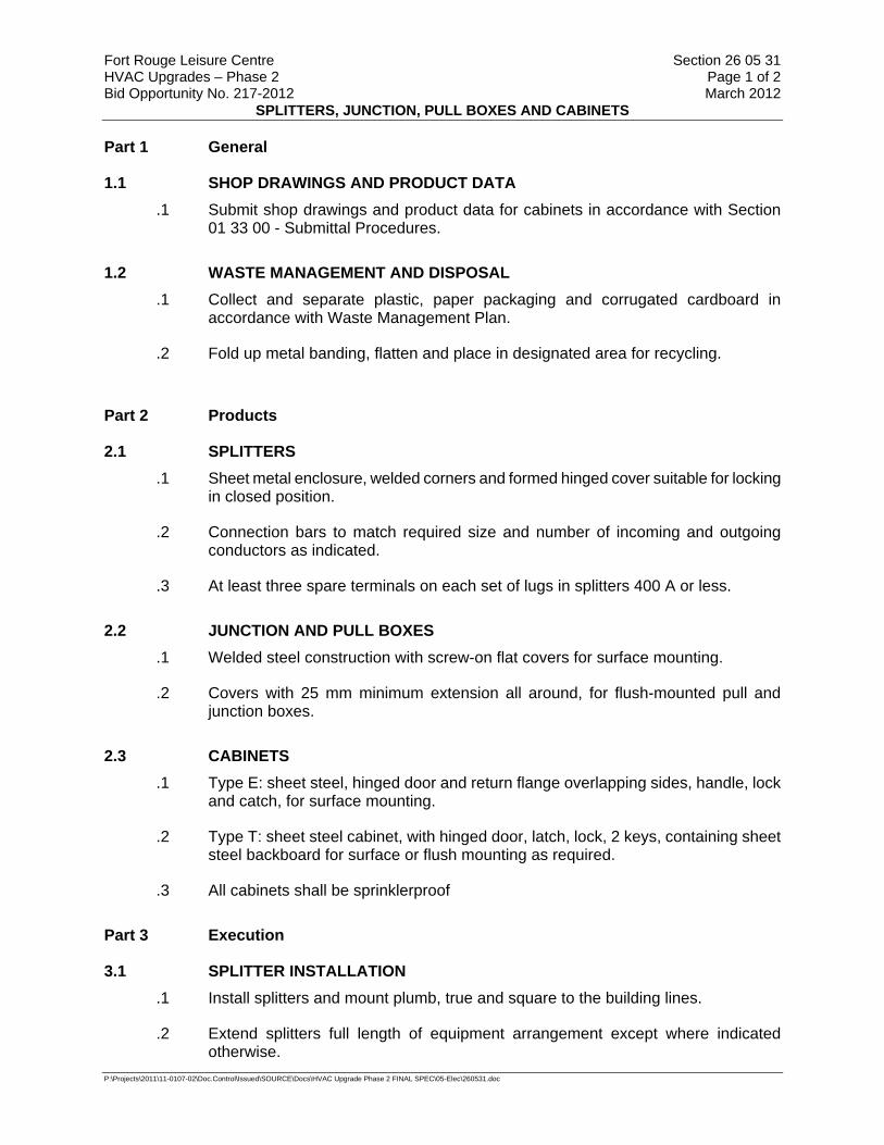
Fort Rouge Leisure Centre Section 26 05 31 HVAC Upgrades – Phase 2 Page 1 of 2 Bid Opportunity No. 217-2012 March 2012
SPLITTERS, JUNCTION, PULL BOXES AND CABINETS
P:\Projects\2011\11-0107-02\Doc.Control\Issued\SOURCE\Docs\HVAC Upgrade Phase 2 FINAL SPEC\05-Elec\260531.doc
Part 1 General
1.1 SHOP DRAWINGS AND PRODUCT DATA .1 Submit shop drawings and product data for cabinets in accordance with Section
01 33 00 - Submittal Procedures.
1.2 WASTE MANAGEMENT AND DISPOSAL .1 Collect and separate plastic, paper packaging and corrugated cardboard in
accordance with Waste Management Plan.
.2 Fold up metal banding, flatten and place in designated area for recycling.
Part 2 Products
2.1 SPLITTERS .1 Sheet metal enclosure, welded corners and formed hinged cover suitable for locking
in closed position.
.2 Connection bars to match required size and number of incoming and outgoing conductors as indicated.
.3 At least three spare terminals on each set of lugs in splitters 400 A or less.
2.2 JUNCTION AND PULL BOXES .1 Welded steel construction with screw-on flat covers for surface mounting.
.2 Covers with 25 mm minimum extension all around, for flush-mounted pull and junction boxes.
2.3 CABINETS .1 Type E: sheet steel, hinged door and return flange overlapping sides, handle, lock
and catch, for surface mounting.
.2 Type T: sheet steel cabinet, with hinged door, latch, lock, 2 keys, containing sheet steel backboard for surface or flush mounting as required.
.3 All cabinets shall be sprinklerproof
Part 3 Execution
3.1 SPLITTER INSTALLATION .1 Install splitters and mount plumb, true and square to the building lines.
.2 Extend splitters full length of equipment arrangement except where indicated otherwise.
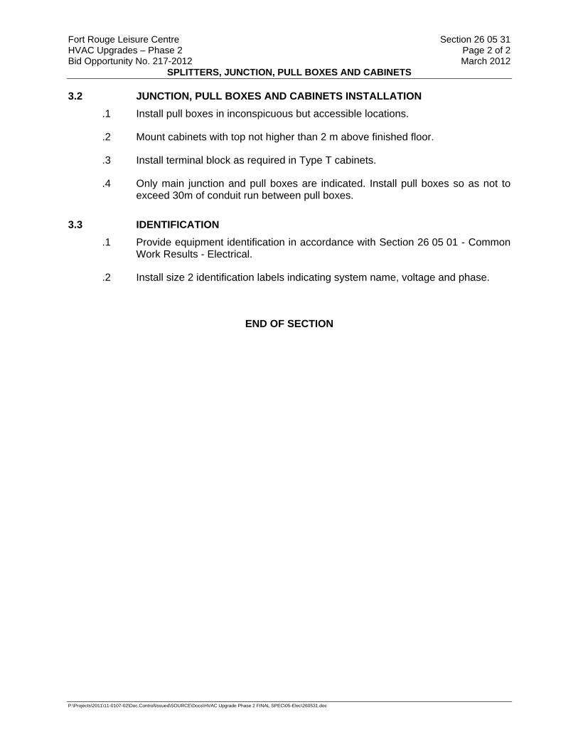
Fort Rouge Leisure Centre Section 26 05 31 HVAC Upgrades – Phase 2 Page 2 of 2 Bid Opportunity No. 217-2012 March 2012
SPLITTERS, JUNCTION, PULL BOXES AND CABINETS
P:\Projects\2011\11-0107-02\Doc.Control\Issued\SOURCE\Docs\HVAC Upgrade Phase 2 FINAL SPEC\05-Elec\260531.doc
3.2 JUNCTION, PULL BOXES AND CABINETS INSTALLATION .1 Install pull boxes in inconspicuous but accessible locations.
.2 Mount cabinets with top not higher than 2 m above finished floor.
.3 Install terminal block as required in Type T cabinets.
.4 Only main junction and pull boxes are indicated. Install pull boxes so as not to exceed 30m of conduit run between pull boxes.
3.3 IDENTIFICATION .1 Provide equipment identification in accordance with Section 26 05 01 - Common
Work Results - Electrical.
.2 Install size 2 identification labels indicating system name, voltage and phase.
END OF SECTION
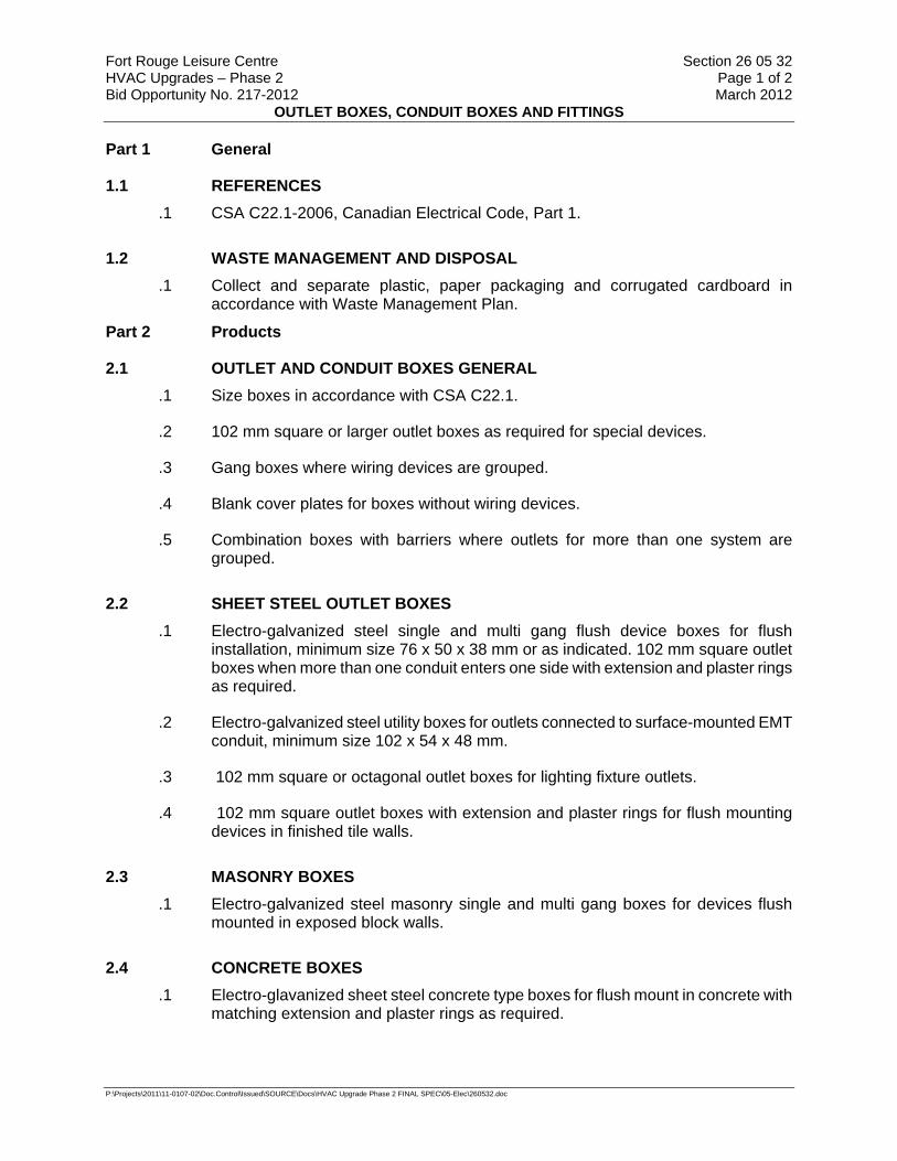
Fort Rouge Leisure Centre Section 26 05 32 HVAC Upgrades – Phase 2 Page 1 of 2 Bid Opportunity No. 217-2012 March 2012
OUTLET BOXES, CONDUIT BOXES AND FITTINGS
P:\Projects\2011\11-0107-02\Doc.Control\Issued\SOURCE\Docs\HVAC Upgrade Phase 2 FINAL SPEC\05-Elec\260532.doc
Part 1 General
1.1 REFERENCES .1 CSA C22.1-2006, Canadian Electrical Code, Part 1.
1.2 WASTE MANAGEMENT AND DISPOSAL .1 Collect and separate plastic, paper packaging and corrugated cardboard in
accordance with Waste Management Plan.
Part 2 Products
2.1 OUTLET AND CONDUIT BOXES GENERAL .1 Size boxes in accordance with CSA C22.1.
.2 102 mm square or larger outlet boxes as required for special devices.
.3 Gang boxes where wiring devices are grouped.
.4 Blank cover plates for boxes without wiring devices.
.5 Combination boxes with barriers where outlets for more than one system are grouped.
2.2 SHEET STEEL OUTLET BOXES .1 Electro-galvanized steel single and multi gang flush device boxes for flush
installation, minimum size 76 x 50 x 38 mm or as indicated. 102 mm square outlet boxes when more than one conduit enters one side with extension and plaster rings as required.
.2 Electro-galvanized steel utility boxes for outlets connected to surface-mounted EMT conduit, minimum size 102 x 54 x 48 mm.
.3 102 mm square or octagonal outlet boxes for lighting fixture outlets.
.4 102 mm square outlet boxes with extension and plaster rings for flush mounting devices in finished tile walls.
2.3 MASONRY BOXES .1 Electro-galvanized steel masonry single and multi gang boxes for devices flush
mounted in exposed block walls.
2.4 CONCRETE BOXES .1 Electro-glavanized sheet steel concrete type boxes for flush mount in concrete with
matching extension and plaster rings as required.
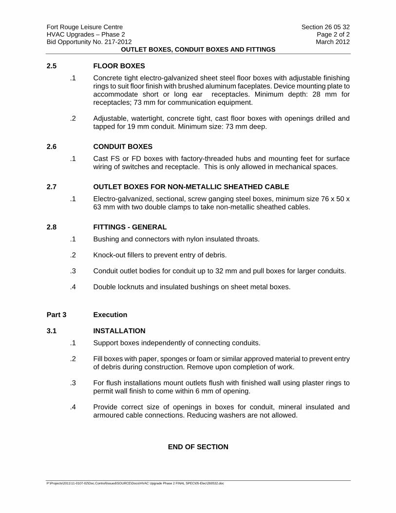
Fort Rouge Leisure Centre Section 26 05 32 HVAC Upgrades – Phase 2 Page 2 of 2 Bid Opportunity No. 217-2012 March 2012
OUTLET BOXES, CONDUIT BOXES AND FITTINGS
P:\Projects\2011\11-0107-02\Doc.Control\Issued\SOURCE\Docs\HVAC Upgrade Phase 2 FINAL SPEC\05-Elec\260532.doc
2.5 FLOOR BOXES .1 Concrete tight electro-galvanized sheet steel floor boxes with adjustable finishing
rings to suit floor finish with brushed aluminum faceplates. Device mounting plate to accommodate short or long ear receptacles. Minimum depth: 28 mm for receptacles; 73 mm for communication equipment.
.2 Adjustable, watertight, concrete tight, cast floor boxes with openings drilled and tapped for 19 mm conduit. Minimum size: 73 mm deep.
2.6 CONDUIT BOXES .1 Cast FS or FD boxes with factory-threaded hubs and mounting feet for surface
wiring of switches and receptacle. This is only allowed in mechanical spaces.
2.7 OUTLET BOXES FOR NON-METALLIC SHEATHED CABLE .1 Electro-galvanized, sectional, screw ganging steel boxes, minimum size 76 x 50 x
63 mm with two double clamps to take non-metallic sheathed cables.
2.8 FITTINGS - GENERAL .1 Bushing and connectors with nylon insulated throats.
.2 Knock-out fillers to prevent entry of debris.
.3 Conduit outlet bodies for conduit up to 32 mm and pull boxes for larger conduits.
.4 Double locknuts and insulated bushings on sheet metal boxes.
Part 3 Execution
3.1 INSTALLATION .1 Support boxes independently of connecting conduits.
.2 Fill boxes with paper, sponges or foam or similar approved material to prevent entry of debris during construction. Remove upon completion of work.
.3 For flush installations mount outlets flush with finished wall using plaster rings to permit wall finish to come within 6 mm of opening.
.4 Provide correct size of openings in boxes for conduit, mineral insulated and armoured cable connections. Reducing washers are not allowed.
END OF SECTION
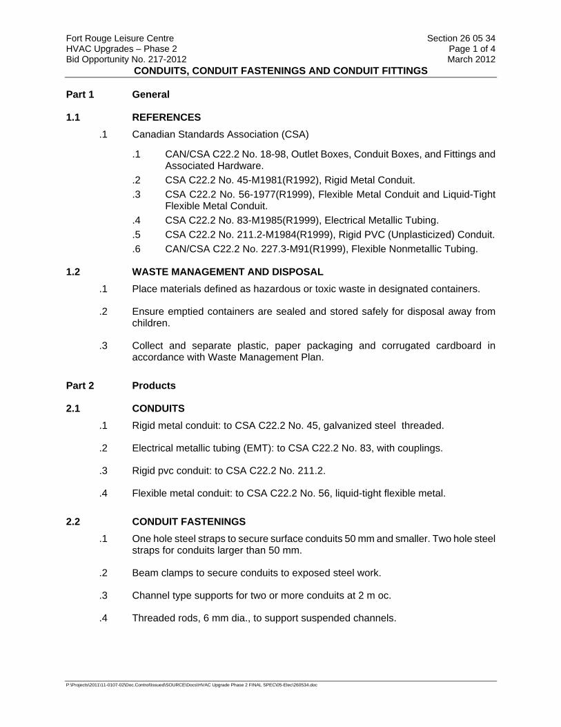
Fort Rouge Leisure Centre Section 26 05 34 HVAC Upgrades – Phase 2 Page 1 of 4 Bid Opportunity No. 217-2012 March 2012
CONDUITS, CONDUIT FASTENINGS AND CONDUIT FITTINGS
P:\Projects\2011\11-0107-02\Doc.Control\Issued\SOURCE\Docs\HVAC Upgrade Phase 2 FINAL SPEC\05-Elec\260534.doc
Part 1 General
1.1 REFERENCES .1 Canadian Standards Association (CSA)
.1 CAN/CSA C22.2 No. 18-98, Outlet Boxes, Conduit Boxes, and Fittings and Associated Hardware.
.2 CSA C22.2 No. 45-M1981(R1992), Rigid Metal Conduit.
.3 CSA C22.2 No. 56-1977(R1999), Flexible Metal Conduit and Liquid-Tight Flexible Metal Conduit.
.4 CSA C22.2 No. 83-M1985(R1999), Electrical Metallic Tubing.
.5 CSA C22.2 No. 211.2-M1984(R1999), Rigid PVC (Unplasticized) Conduit.
.6 CAN/CSA C22.2 No. 227.3-M91(R1999), Flexible Nonmetallic Tubing.
1.2 WASTE MANAGEMENT AND DISPOSAL .1 Place materials defined as hazardous or toxic waste in designated containers.
.2 Ensure emptied containers are sealed and stored safely for disposal away from children.
.3 Collect and separate plastic, paper packaging and corrugated cardboard in accordance with Waste Management Plan.
Part 2 Products
2.1 CONDUITS .1 Rigid metal conduit: to CSA C22.2 No. 45, galvanized steel threaded.
.2 Electrical metallic tubing (EMT): to CSA C22.2 No. 83, with couplings.
.3 Rigid pvc conduit: to CSA C22.2 No. 211.2.
.4 Flexible metal conduit: to CSA C22.2 No. 56, liquid-tight flexible metal.
2.2 CONDUIT FASTENINGS .1 One hole steel straps to secure surface conduits 50 mm and smaller. Two hole steel
straps for conduits larger than 50 mm.
.2 Beam clamps to secure conduits to exposed steel work.
.3 Channel type supports for two or more conduits at 2 m oc.
.4 Threaded rods, 6 mm dia., to support suspended channels.
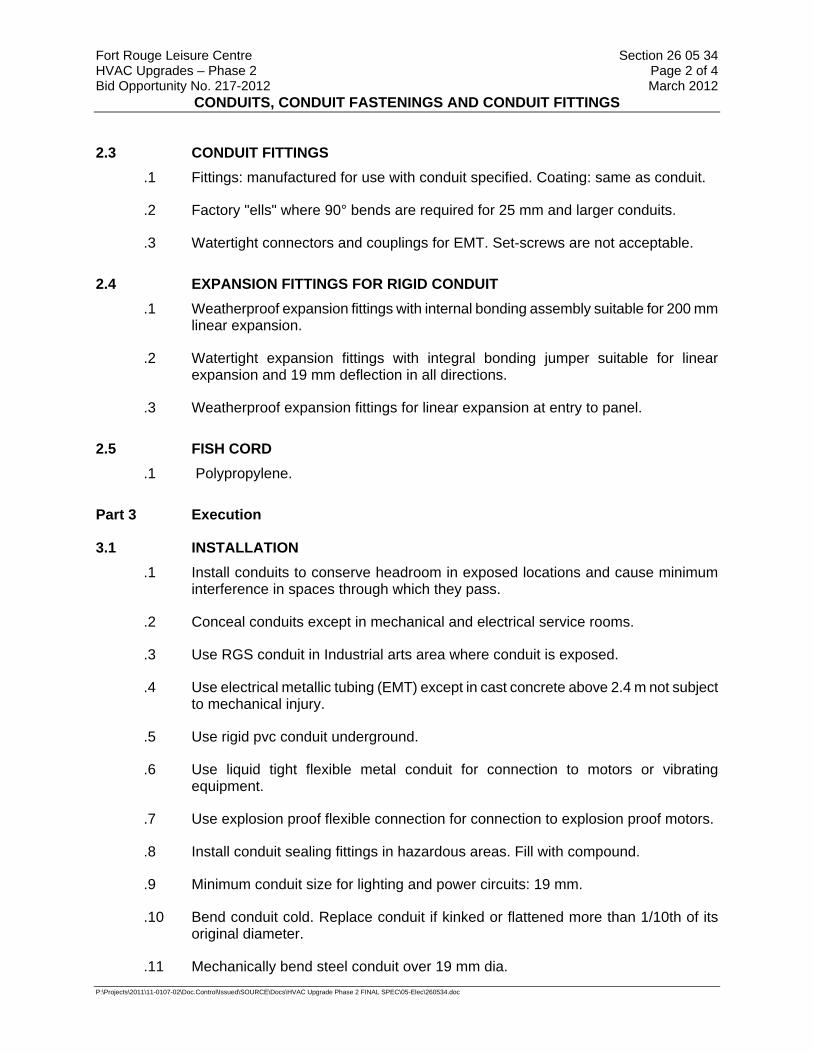
Fort Rouge Leisure Centre Section 26 05 34 HVAC Upgrades – Phase 2 Page 2 of 4 Bid Opportunity No. 217-2012 March 2012
CONDUITS, CONDUIT FASTENINGS AND CONDUIT FITTINGS
P:\Projects\2011\11-0107-02\Doc.Control\Issued\SOURCE\Docs\HVAC Upgrade Phase 2 FINAL SPEC\05-Elec\260534.doc
2.3 CONDUIT FITTINGS .1 Fittings: manufactured for use with conduit specified. Coating: same as conduit.
.2 Factory "ells" where 90° bends are required for 25 mm and larger conduits.
.3 Watertight connectors and couplings for EMT. Set-screws are not acceptable.
2.4 EXPANSION FITTINGS FOR RIGID CONDUIT .1 Weatherproof expansion fittings with internal bonding assembly suitable for 200 mm
linear expansion.
.2 Watertight expansion fittings with integral bonding jumper suitable for linear expansion and 19 mm deflection in all directions.
.3 Weatherproof expansion fittings for linear expansion at entry to panel.
2.5 FISH CORD .1 Polypropylene.
Part 3 Execution
3.1 INSTALLATION .1 Install conduits to conserve headroom in exposed locations and cause minimum
interference in spaces through which they pass.
.2 Conceal conduits except in mechanical and electrical service rooms.
.3 Use RGS conduit in Industrial arts area where conduit is exposed.
.4 Use electrical metallic tubing (EMT) except in cast concrete above 2.4 m not subject to mechanical injury.
.5 Use rigid pvc conduit underground.
.6 Use liquid tight flexible metal conduit for connection to motors or vibrating equipment.
.7 Use explosion proof flexible connection for connection to explosion proof motors.
.8 Install conduit sealing fittings in hazardous areas. Fill with compound.
.9 Minimum conduit size for lighting and power circuits: 19 mm.
.10 Bend conduit cold. Replace conduit if kinked or flattened more than 1/10th of its original diameter.
.11 Mechanically bend steel conduit over 19 mm dia.
Fort Rouge Leisure Centre Section 26 05 34 HVAC Upgrades – Phase 2 Page 3 of 4 Bid Opportunity No. 217-2012 March 2012
CONDUITS, CONDUIT FASTENINGS AND CONDUIT FITTINGS
P:\Projects\2011\11-0107-02\Doc.Control\Issued\SOURCE\Docs\HVAC Upgrade Phase 2 FINAL SPEC\05-Elec\260534.doc
.12 Field threads on rigid conduit must be of sufficient length to draw conduits up tight.
.13 Install fish cord in empty conduits.
.14 Run 2-25 mm spare conduits up to ceiling space from each flush panel. Terminate these conduits in 152 x 152 x 102 mm junction boxes in ceiling space or in case of an exposed concrete slab, terminate each conduit in surface type box.
.15 Remove and replace blocked conduit sections. Do not use liquids to clean out conduits.
.16 Dry conduits out before installing wire.
3.2 SURFACE CONDUITS .1 Run parallel or perpendicular to building lines.
.2 Locate conduits behind infrared or gas fired heaters with 1.5 m clearance.
.3 Run conduits in flanged portion of structural steel.
.4 Group conduits wherever possible on surface channels.
.5 Do not pass conduits through structural members except as indicated.
.6 Do not locate conduits less than 75 mm parallel to steam or hot water lines with minimum of 25 mm at crossovers.
.7 Surface conduits shall not be used where exposed.
3.3 CONCEALED CONDUITS .1 Run parallel or perpendicular to building lines.
.2 Do not install horizontal runs in masonry walls.
.3 Do not install conduits in terrazzo or concrete toppings.
3.4 CONDUITS IN CAST-IN-PLACE CONCRETE .1 Locate to suit reinforcing steel. Install in centre one third of slab.
.2 Protect conduits from damage where they stub out of concrete.
.3 Install sleeves where conduits pass through slab or wall.
.4 Provide oversized sleeve for conduits passing through waterproof membrane, before membrane is installed. Use cold mastic between sleeve and conduit.
.5 Do not place conduits is slabs in which slab thickness is less than 4 times conduit diameter.
Fort Rouge Leisure Centre Section 26 05 34 HVAC Upgrades – Phase 2 Page 4 of 4 Bid Opportunity No. 217-2012 March 2012
CONDUITS, CONDUIT FASTENINGS AND CONDUIT FITTINGS
P:\Projects\2011\11-0107-02\Doc.Control\Issued\SOURCE\Docs\HVAC Upgrade Phase 2 FINAL SPEC\05-Elec\260534.doc
.6 Encase conduits completely in concrete with minimum 25 mm concrete cover.
.7 Organize conduits in slab to minimize cross-overs.
3.5 CONDUITS UNDERGROUND .1 Slope conduits to provide drainage.
END OF SECTION

Fort Rouge Leisure Centre Section 26 05 80 HVAC Upgrades - Phase 2 Page 1 of 2 Bid Opportunity No. 217-2012 March 2012
FRACTIONAL HORSEPOWER MOTORS
P:\Projects\2011\11-0107-02\Doc.Control\Issued\SOURCE\Docs\HVAC Upgrade Phase 2 FINAL SPEC\05-Elec\260580.DOC
Part 1 General
1.1 REFERENCES .1 Canadian Standards Association (CSA International)
.1 CSA C22.2 No. 100-04, Motors and Generators.
.2 CSA C22.2 No. 145-M1986(R2004), Motors and Generators for Use in Hazardous Locations.
.2 Electrical and Electronic Manufacturers' Association of Canada (EEMAC)
.1 EEMAC M1-7-[1992], Standard for Motors and Generators.
1.2 SUBMITTALS .1 Submittals: in accordance with Section 01 33 00 - Submittal Procedures.
.2 Product Data: include: product characteristics, performance criteria, physical size, horsepower, watt rating, limitations and finish.
.3 Shop drawings:
.1 Indicate dimensions, recommended installation procedure, wiring diagrams, sizes and location of mounting bolt holes and recommended support method.
.4 Quality Assurance Submittals:
.1 Certificates: submit certificates signed by manufacturer certifying that materials comply with specified performance characteristics and physical properties.
.2 Manufacturer's Instructions: submit manufacturer's installation instructions.
.5 Closeout Submittals:
.1 Provide maintenance data for fractional horsepower motors for incorporation into manual specified in Section 01 78 00 - Closeout Submittals.
Part 2 Products
2.1 FRACTIONAL HORSEPOWER MOTOR .1 Non-hazardous locations: to CSA C22.2 No. 100 and EEMAC M1-7.
.2 Hazardous locations: to CSA C22.2 No. 145.
.1 Rating: As indicated.
.2 Type: As indicated.
.3 Bearings: As indicated.
.4 Frame size: As indicated.
.5 Enclosure: As indicated.
.6 Mounting: As indicated.
.3 Motor with inherent overheating protectors.

Fort Rouge Leisure Centre Section 26 05 80 HVAC Upgrades - Phase 2 Page 2 of 2 Bid Opportunity No. 217-2012 March 2012
FRACTIONAL HORSEPOWER MOTORS
P:\Projects\2011\11-0107-02\Doc.Control\Issued\SOURCE\Docs\HVAC Upgrade Phase 2 FINAL SPEC\05-Elec\260580.DOC
Part 3 Execution
3.1 MANUFACTURER'S INSTRUCTIONS .1 Compliance: comply with manufacturer's written recommendations or specifications,
including product technical bulletins, handling, storage and installation instructions, and datasheets.
3.2 INSTALLATION .1 Install wiring, flexible connections and grounding.
.2 Check rotation before coupling to driven equipment.
3.3 CLEANING .1 On completion and verification of performance of installation, remove surplus
materials, excess materials, rubbish, tools and equipment.
END OF SECTION
Fort Rouge Leisure Centre Section 26 05 81 HVAC Upgrades – Phase 2 Page 1 of 3 Bid Opportunity No. 217-2012 March 2012
MOTORS: 1 TO 200 HPKW TO 149KW, TO 600 V
P:\Projects\2011\11-0107-02\Doc.Control\ToBeIssued\Other\260581.doc
Part 1 General
1.1 REFERENCES .1 Electrical and Electronic Manufacturer’s Association of Canada (EEMAC)
.1 EEMAC M1-7, 1992, Motors and Generators.
1.2 PRODUCT DATA .1 Submit product data in accordance with Section 01 33 00 - Submittal Procedures.
.2 Submit product data sheets for motors. Include product characteristics, performance criteria, physical size, horsepower, watt rating, limitations and finish.
.3 Manufacturer’s Instructions: Provide to indicate special handling criteria, installation sequence, cleaning procedures.
1.3 SHOP DRAWINGS .1 Submit shop drawings in accordance with Section 01 33 00 - Submittal Procedures.
.2 Indicate:
.1 Overall dimensions of motor.
.2 Shaft centreline to base dimension.
.3 Shaft extension diameter and keyway, coupling dimensions and details.
.4 Fixing support dimensions.
.5 Dimensioned position of ventilation openings. Details of ventilation duct attachments.
.6 Terminal box location and size of terminals.
.7 Arrangement and dimensions of accessories.
.8 Diagram of connections.
.9 Starting current and relative data necessary for use in design of motor starting equipment.
.10 Speed/torque characteristic.
.11 Weight.
.12 Installation data.
1.4 CLOSEOUT SUBMITTALS .1 Provide maintenance data for motors for incorporation into manual specified in
Section 01 78 00 - Closeout Submittals. .2 Data necessary for maintenance of motors. .3 Manufacturer's recommended list of spare parts.
1.5 DELIVERY, STORAGE AND HANDLING .1 Handle motors with suitable lifting equipment. .2 Store motors in heated, dry, weather-protected enclosure.
1.6 QUALITY ASSURANCE .1 Contract Administrator reserves the right to witness standard factory testing of
motors 50 hp and above.

Fort Rouge Leisure Centre Section 26 05 81 HVAC Upgrades – Phase 2 Page 2 of 3 Bid Opportunity No. 217-2012 March 2012
MOTORS: 1 TO 200 HPKW TO 149KW, TO 600 V
P:\Projects\2011\11-0107-02\Doc.Control\ToBeIssued\Other\260581.doc
1.7 WASTE MANAGEMENT AND DISPOSAL .1 Place materials defined as hazardous or toxic waste in designated containers.
.2 Ensure emptied containers are sealed and stored safely for disposal away from children.
.3 Collect and separate plastic, paper packaging and corrugated cardboard in accordance with Waste Management Plan.
.4 Fold up metal banding, flatten and place in designated area for recycling.
.5 Collect, package and store expired motors for either recycling or rebuilding and return to recycler or rebuilder.
1.8 EXTRA MATERIALS .1 Provide maintenance materials and spare parts in accordance with Section 01 78 00
- Closeout Submittals.
Part 2 Products
2.1 MATERIALS .1 Motors: to EEMAC M1-7.
.2 Lead markings: to EEMAC M2-1.
2.2 RATING .1 Motor:
.1 As indicated
2.3 MOTOR TYPE .1 As Indicated.
2.4 DESIGN LETTERS .1 Polyphase squirrel cage induction motors design As Indicated.
2.5 ENCLOSURE .1 Totally enclosed fan cooled.
.2 Totally enclosed explosion proof for use in: Class as Indicated.
2.6 SERVICE CONDITIONS .1 Service Factor: 1.15.
Fort Rouge Leisure Centre Section 26 05 81 HVAC Upgrades – Phase 2 Page 3 of 3 Bid Opportunity No. 217-2012 March 2012
MOTORS: 1 TO 200 HPKW TO 149KW, TO 600 V
P:\Projects\2011\11-0107-02\Doc.Control\ToBeIssued\Other\260581.doc
2.7 INSULATION .1 Class: B or As Indicated..
.2 Ambient temperature: 40 ºC or As indicated.
2.8 BEARINGS .1 Antifriction type bearings, fitted with readily accessible facilities for lubrication while
motor running or stationary.
2.9 STARTING METHOD .1 All motors shall be Inverter Duty rated.
.2 Include anchor devices and setting templates.
Part 3 Execution
3.1 INSTALLATION .1 Dry out motor if dampness present in accordance with manufacturer's instructions.
.2 Install motor.
.3 Make wiring connections. Use liquid tight pvc jacketed flexible conduit between rigid conduit and motor.
.4 Make flexible conduit long enough to permit movement of motor over entire length of slide rails.
.5 Check for correct direction of rotation, with motor uncoupled from driven equipment.
.6 Align and couple motor to driven machinery to manufacturer's instructions, using only correct parts such as couplings, belts, sheaves, as provided by manufacturer.
3.2 FIELD QUALITY CONTROL .1 Perform tests in accordance with Section 26 05 01 - Common Work Results –
Electrical.
END OF SECTION
Fort Rouge Leisure Centre Section 26 24 17 HVAC Upgrades – Phase 2 Page 1 of 3 Bid Opportunity No. 217-2012 March 2012
PANELBOARDS BREAKER TYPE
P:\Projects\2011\11-0107-02\Doc.Control\Issued\SOURCE\Docs\HVAC Upgrade Phase 2 FINAL SPEC\05-Elec\262417.doc
Part 1 General
1.1 SECTION INCLUDES .1 Materials and installation for standard and custom breaker type panelboards.
1.2 RELATED SECTIONS .1 Section 01 33 00 - Submittal Procedures. .2 Section 26 05 01 - Common Work Results - Electrical.
1.3 REFERENCES .1 Canadian Standards Association (CSA International)
.1 CSA C22.2 No.29-M1989(R2000), Panelboards and enclosed Panelboards.
1.4 SHOP DRAWINGS .1 Submit shop drawings in accordance with Section 01 33 00 - Submittal Procedures.
.2 Drawings to include electrical detail of panel, branch breaker type, quantity, ampacity and enclosure dimension.
Part 2 Products
2.1 PANELBOARDS .1 Panelboards: to CSA C22.2 No.29 and product of one manufacturer.
.1 Install circuit breakers in panelboards before shipment.
.2 In addition to CSA requirements manufacturer's nameplate must show fault current that panel including breakers has been built to withstand.
.2 250V panelboards: bus and breakers rated for 25 kA (symmetrical) interrupting capacity or as indicated.
.3 600V panelboards: bus and breakers rated for 35 kA (symmetrical) interrupting capacity or as indicated.
.4 Sequence phase bussing with odd numbered breakers on left and even on right, with each breaker identified by permanent number identification as to circuit number and phase.
.5 Panelboards: mains, number of circuits, and number and size of branch circuit breakers as indicated.
.6 Two keys for each panelboard and key panelboards alike.
.7 Copper bus with neutral of same ampere rating as mains and 200% neutral where indicated.
.8 Mains: suitable for bolt-on breakers or as required for replacement.
.9 Trim with concealed front bolts and hinges.

Fort Rouge Leisure Centre Section 26 24 17 HVAC Upgrades – Phase 2 Page 2 of 3 Bid Opportunity No. 217-2012 March 2012
PANELBOARDS BREAKER TYPE
P:\Projects\2011\11-0107-02\Doc.Control\Issued\SOURCE\Docs\HVAC Upgrade Phase 2 FINAL SPEC\05-Elec\262417.doc
.10 Trim and door finish: baked grey enamel.
2.2 CUSTOM BUILT PANELBOARD ASSEMBLIES .1 Double stack panels as indicated.
.2 Contactors in mains as indicated.
.3 Feed through lugs as indicated.
.4 Isolated ground bus.
2.3 BREAKERS .1 Breakers with thermal and magnetic tripping in panelboards except as indicated
otherwise.
.2 Main breaker: separately mounted on top or bottom of panel to suit cable entry. When mounted vertically, down position should open breaker.
.3 Lock-on devices for 10% of 15 to 30A breakers installed as indicated. Turn over unused lock-on devices to Departmental Representative.
.4 Lock-on devices for fire alarm, emergency, door supervisory, Security, exit and night light circuits.
2.4 TVSS .1 Provide TVSS unit with digital indication and 100kA rating where indicated.
2.5 EQUIPMENT IDENTIFICATION .1 Provide equipment identification in accordance with Section 26 05 01 - Common
Work Results - Electrical.
.2 Nameplate for each panelboard size 4 engraved as indicated.
.3 Nameplate for each circuit in distribution panelboards size 2 engraved as indicated.
.4 Complete circuit directory with typewritten legend showing location and load of each circuit.
Part 3 Execution
3.1 INSTALLATION .1 Locate panelboards as indicated and mount securely, plumb, true and square, to
adjoining surfaces.
.2 Install surface mounted panelboards on plywood backboards. Where practical, group panelboards on common backboard.
Fort Rouge Leisure Centre Section 26 24 17 HVAC Upgrades – Phase 2 Page 3 of 3 Bid Opportunity No. 217-2012 March 2012
PANELBOARDS BREAKER TYPE
P:\Projects\2011\11-0107-02\Doc.Control\Issued\SOURCE\Docs\HVAC Upgrade Phase 2 FINAL SPEC\05-Elec\262417.doc
.3 Mount panelboards to height specified in Section 26 05 01 - Common Work Results - Electrical or as indicated.
.4 Connect loads to circuits.
.5 Connect neutral conductors to common neutral bus with respective neutral identified.
END OF SECTION
Fort Rouge Leisure Centre Section 26 27 16 HVAC Upgrades – Phase 2 Page 1 of 2 Bid Opportunity No. 217-2012 March 2012
ELECTRICAL CABINETS AND ENCLOSURES
P:\Projects\2011\11-0107-02\Doc.Control\Issued\SOURCE\Docs\HVAC Upgrade Phase 2 FINAL SPEC\05-Elec\262716.doc
Part 1 General
1.1 RELATED SECTIONS .1 Section 01 33 00 - Submittal Procedures.
1.2 REFERENCES .1 The Munsell System of Colour Notation.
1.3 SHOP DRAWINGS AND PRODUCT DATA .1 Submit shop drawings and product data in accordance with Section 01 33 00 -
Submittal Procedures.
Part 2 Products
2.1 MATERIALS .1 Enclosure constructed with 2.7 mm thick minimum steel, with weather and corrosion
resistant finish, Munsell Notation 7.5GY3.5/1.5, size as indicated.
.2 Entire enclosure capable of withstanding maximum impact force of 86 MN/m2 area without rupture of material.
.3 Removable enclosure panels with formed edges, galvanized steel external fasteners removable only from inside enclosure.
.4 Enclosure equipped with hot dipped galvanized mounting rails 1 m adjustable horizontally and vertically to enable mounting of equipment at any location within housing.
.1 Rails: 14 mm holes and 50 x 14 mm slots on 100 mm centres for horizontal adjustment.
.2 Holes in side panel flanges in 60 mm increments for vertical adjustment.
.5 Cover: tamperproof, bolt-on, domed to shed water.
.6 Door: minimum 1 m wide, hinged, 3 point latching, with padlocking means.
.7 Ventilation panel constructed to allow air circulation yet preventing entry of foreign objects, wild life, vermin.
.8 Door interlocks: as required.
.9 Enclosure construction such as to allow any configuration of single or ganged enclosures.
.10 Enclosure capable of being shipped in knocked-down condition.

Fort Rouge Leisure Centre Section 26 27 16 HVAC Upgrades – Phase 2 Page 2 of 2 Bid Opportunity No. 217-2012 March 2012
ELECTRICAL CABINETS AND ENCLOSURES
P:\Projects\2011\11-0107-02\Doc.Control\Issued\SOURCE\Docs\HVAC Upgrade Phase 2 FINAL SPEC\05-Elec\262716.doc
Part 3 Execution
3.1 INSTALLATION .1 Assemble enclosure in accordance with manufacturer's instructions and mount on
concrete pad.
.2 Mount equipment in enclosure.
END OF SECTION

Fort Rouge Leisure Centre Section 26 27 26 HVAC Upgrades – Phase 2 Page 1 of 3 Bid Opportunity No. 217-2012 March 2012
WIRING DEVICES
P:\Projects\2011\11-0107-02\Doc.Control\Issued\SOURCE\Docs\HVAC Upgrade Phase 2 FINAL SPEC\05-Elec\262726.doc
Part 1 General
1.1 SECTION INCLUDES .1 Switches, receptacles, wiring devices, cover plates and their installation.
1.2 RELATED SECTIONS .1 Section 01 33 00 - Submittal Procedures.
.2 Section 26 05 01 - Common Work Results - Electrical.
1.3 REFERENCES .1 Canadian Standards Association (CSA International)
.1 CSA-C22.2 No.42-99(R2002), General Use Receptacles, Attachment Plugs and Similar Devices.
.2 CSA-C22.2 No.42.1-00, Cover Plates for Flush-Mounted Wiring Devices (Bi-national standard, with UL 514D).
.3 CSA-C22.2 No.55-M1986(July 2001), Special Use Switches.
.4 CSA-C22.2 No.111-00, General-Use Snap Switches (Bi-national standard, with UL 20, twelfth edition).
1.4 SHOP DRAWINGS AND PRODUCT DATA .1 Submit shop drawings and product data in accordance with Section 01 33 00 -
Submittal Procedures.
Part 2 Products
2.1 SWITCHES .1 15 or 20 A, 120 V, single pole, three-way, or four-way switches to: CSA-C22.2
No.55 and CSA-C22.2 No.111.
.2 Manually-operated general purpose ac switches with following features:
.1 Terminal holes approved for No. 10 AWG wire.
.2 Silver alloy contacts.
.3 Urea or melamine moulding for parts subject to carbon tracking.
.4 Suitable for back and side wiring.
.5 White toggle.
.3 Toggle operated fully rated for tungsten filament and fluorescent lamps, and up to 80% of rated capacity of motor loads.
.4 Switches of one manufacturer throughout project.
.5 Acceptable materials: Specification Grade Commercial switches.
Fort Rouge Leisure Centre Section 26 27 26 HVAC Upgrades – Phase 2 Page 2 of 3 Bid Opportunity No. 217-2012 March 2012
WIRING DEVICES
P:\Projects\2011\11-0107-02\Doc.Control\Issued\SOURCE\Docs\HVAC Upgrade Phase 2 FINAL SPEC\05-Elec\262726.doc
2.2 RECEPTACLES .1 Duplex receptacles, CSA type 5-15 R, 125 V, 15 A, U ground, to: CSA-C22.2 No.42
with following features:
.1 White urea moulded housing for normal switches. Co-ordinate with owner for all unique coloured switches. (Red- UPS, Orange – IG Wiring Type)
.2 Suitable for No. 10 AWG for back and side wiring.
.3 Break-off links for use as split receptacles.
.4 Eight back wired entrances, four side wiring screws.
.5 Triple wipe contacts and riveted grounding contacts.
.2 Other receptacles with ampacity and voltage as indicated.
.3 Receptacles of one manufacturer throughout project.
.4 Acceptable materials: Specification Grade Commercial switches.
2.3 COVER PLATES .1 Cover plates for wiring devices to: CSA-C22.2 No.42.1.
.2 Cover plates from one manufacturer throughout project.
.3 Sheet steel utility box cover for wiring devices installed in surface-mounted utility boxes.
.4 Stainless steel, vertically brushed, 1 mm thick cover plates for wiring devices mounted in flush-mounted outlet box.
.5 Sheet metal cover plates for wiring devices mounted in surface-mounted FS or FD type conduit boxes.
.6 Weatherproof double lift spring-loaded cast aluminum cover plates, complete with gaskets for duplex receptacles as indicated.
.7 Weatherproof spring-loaded cast aluminum cover plates complete with gaskets for single receptacles or switches.
Part 3 Execution
3.1 INSTALLATION .1 Switches:
.1 Install single throw switches with handle in "UP" position when switch closed.
.2 Install switches in gang type outlet box when more than one switch is required in one location.
.3 Mount toggle switches at height in accordance with Section 26 05 01 - Common Work Results - Electrical.
Fort Rouge Leisure Centre Section 26 27 26 HVAC Upgrades – Phase 2 Page 3 of 3 Bid Opportunity No. 217-2012 March 2012
WIRING DEVICES
P:\Projects\2011\11-0107-02\Doc.Control\Issued\SOURCE\Docs\HVAC Upgrade Phase 2 FINAL SPEC\05-Elec\262726.doc
.2 Receptacles:
.1 Install receptacles in gang type outlet box when more than one receptacle is required in one location.
.2 Mount receptacles at height in accordance with Section 26 05 01 - Common Work Results - Electrical.
.3 Where split receptacle has one portion switched, mount vertically and switch upper portion.
.3 Cover plates:
.1 Protect stainless steel cover plate finish with paper or plastic film until painting and other work is finished.
.2 Install suitable common cover plates where wiring devices are grouped.
.3 Do not use cover plates meant for flush outlet boxes on surface-mounted boxes.
END OF SECTION

Fort Rouge Leisure Centre Section 26 28 23 HVAC Upgrades –Phase 2 Page 1 of 2 Bid Opportunity No. 217-2012 March 2012
DISCONNECT SWITCHES - FUSED AND NON-FUSED
P:\Projects\2011\11-0107-02\Doc.Control\Issued\SOURCE\Docs\HVAC Upgrade Phase 2 FINAL SPEC\05-Elec\262823.doc
Part 1 General
1.1 SECTION INCLUDES .1 Materials and installation for fused and non-fused disconnect switches.
1.2 RELATED SECTIONS .1 Section 01 33 00 - Submittal Procedures.
.2 Section 26 05 01 - Common Work Results - Electrical.
1.3 REFERENCES .1 Canadian Standards Association (CSA International).
.1 CAN/CSA C22.2 No.4-M89 (R2000), Enclosed Switches.
.2 CSA C22.2 No.39-M89 (R2003), Fuseholder Assemblies.
1.4 SUBMITTALS .1 Submit product data in accordance with Section 01 33 00 - Submittal Procedures.
Part 2 Products
2.1 DISCONNECT SWITCHES .1 Non-fusible, horsepower rated disconnect switch in CSA Enclosure, to CAN/CSA
C22.2 No.4 sized as per drawings.
.2 Provision for padlocking in off switch position by three locks.
.3 Mechanically interlocked door to prevent opening when handle in ON position.
.4 Sprinkler-proof indoors, weatherproof outdoors.
.5 Quick-make, quick-break action.
.6 ON-OFF switch position indication on switch enclosure cover.
.7 Where required (For VFDs) provide an auxilliary contact to break prior to main contacts and interlock with the VFD emergency stop.
2.2 EQUIPMENT IDENTIFICATION .1 Provide equipment identification in accordance with Section 26 05 01 - Common
Work Results - Electrical.
.2 Indicate name of load controlled on size 4 nameplate.
Fort Rouge Leisure Centre Section 26 28 23 HVAC Upgrades –Phase 2 Page 2 of 2 Bid Opportunity No. 217-2012 March 2012
DISCONNECT SWITCHES - FUSED AND NON-FUSED
P:\Projects\2011\11-0107-02\Doc.Control\Issued\SOURCE\Docs\HVAC Upgrade Phase 2 FINAL SPEC\05-Elec\262823.doc
Part 3 Execution
3.1 INSTALLATION .1 Install disconnect switches.
END OF SECTION
Fort Rouge Leisure Centre Section 26 29 01 HVAC Upgrades – Phase 2 Page 1 of 2 Bid Opportunity No. 217-2012 March 2012
CONTACTORS
P:\Projects\2011\11-0107-02\Doc.Control\Issued\SOURCE\Docs\HVAC Upgrade Phase 2 FINAL SPEC\05-Elec\262901.doc
Part 1 General
1.1 SECTION INCLUDES .1 Materials and installation for contactors for system voltages up to 600 V
1.2 RELATED SECTIONS .1 Section 01 33 00 - Submittal Procedures.
.2 Section 26 05 01 - Common Work Results - Electrical.
.3 Section 26 29 03 - Control Devices.
1.3 REFERENCES .1 Canadian Standards Association (CSA International)
.1 CSA C22.2 No.14-95 (R2001), Industrial Control Equipment.
1.4 PRODUCT DATA .1 Submit product data in accordance with Section 01 33 00 - Submittal
Procedures.
Part 2 Products
2.1 CONTACTORS .1 Contactors: to CSA C22.2 No.14.
.2 Electrically held controlled by pilot devices as indicated and rated for type of load controlled.
.3 Fused switch combination contactor as indicated.
.4 Complete with 2 normally open and 2 normally closed auxiliary contacts unless indicated otherwise.
.5 Mount in CSA Enclosure unless otherwise indicated.
.6 Include following options in cover:
.1 Red LED indicating lamp.
.2 Hand-Off-Auto selector switch.
.7 Control transformer: in accordance with Section 26 29 03 - Control Devices, in contactor enclosure.
2.2 EQUIPMENT IDENTIFICATION .1 Provide equipment identification in accordance with Section 26 05 01 - Common
Work Results - Electrical.
.2 Size 4 nameplate indicating name of load controlled.
Fort Rouge Leisure Centre Section 26 29 01 HVAC Upgrades – Phase 2 Page 2 of 2 Bid Opportunity No. 217-2012 March 2012
CONTACTORS
P:\Projects\2011\11-0107-02\Doc.Control\Issued\SOURCE\Docs\HVAC Upgrade Phase 2 FINAL SPEC\05-Elec\262901.doc
Part 3 Execution
3.1 INSTALLATION .1 Install contactors and connect auxiliary control devices.
END OF SECTION
Fort Rouge Leisure Centre Section 26 29 03 HVAC Upgrades – Phase 2 Page 1 of 2 Bid Opportunity No. 217-2012 March 2012
CONTROL DEVICES
P:\Projects\2011\11-0107-02\Doc.Control\Issued\SOURCE\Docs\HVAC Upgrade Phase 2 FINAL SPEC\05-Elec\262903.doc
Part 1 General
1.1 SECTION INCLUDES .1 Materials and installation for industrial control devices including pushbutton stations,
control and relay panels.
1.2 RELATED SECTIONS .1 Section 01 33 00 - Submittal Procedures.
.2 Section 26 05 01 - Common Work Results - Electrical.
1.3 REFERENCES .1 Canadian Standards Association (CSA International)
.1 CSA C22.2 No.14-95(R2001), Industrial Control Equipment. .2 National Electrical Manufacturers Association (NEMA)
.1 NEMA ICS 1-2001, Industrial Control and Systems: General Requirements.
1.4 SHOP DRAWINGS .1 Submit shop drawings in accordance with Section 01 33 00 - Submittal Procedures.
.2 Include schematic, wiring, interconnection diagrams.
1.5 QUALITY ASSURANCE .1 Submit to Contract Administrator one copy of test results.
Part 2 Products
2.1 AC CONTROL RELAYS .1 Control Relays: to CSA C22.2 No.14 and NEMA ICS 1.
.2 Convertible contact type: contacts field convertible from NO to NC, electrically held solid state. Contact rating: as required.
2.2 RELAY ACCESSORIES .1 Standard contact cartridges: normally-open - convertible to normally-closed in field.
2.3 OPERATOR CONTROL STATIONS .1 Enclosure: CSA Type 4, flush mounting:
2.4 PUSHBUTTONS .1 Illuminated, Heavy duty Oil tight. Operator flush type, as indicated. With 1-NO and
1-NC contacts rated at as required.
Fort Rouge Leisure Centre Section 26 29 03 HVAC Upgrades – Phase 2 Page 2 of 2 Bid Opportunity No. 217-2012 March 2012
CONTROL DEVICES
P:\Projects\2011\11-0107-02\Doc.Control\Issued\SOURCE\Docs\HVAC Upgrade Phase 2 FINAL SPEC\05-Elec\262903.doc
2.5 SELECTOR SWITCHES .1 Maintained 3 position labelled as indicated heavy duty oil tight, operators standard,
contact arrangement as indicated.
2.6 INDICATING LIGHTS .1 Heavy duty Oil tight, full voltage, LED type, as indicated.
2.7 CONTROL AND RELAY PANELS .1 CSA Type sprinklerproof sheet steel enclosure with hinged padlockable access
door, accommodating relays timers, labels, as indicated, factory installed and wired to identified terminals.
2.8 CONTROL CIRCUIT TRANSFORMERS .1 Single phase, dry type. .2 Primary: 208 V, 60 Hz ac. .3 Secondary: 24 or 120 V, AC. As required .4 Rating: VA rating as shown. .5 Secondary fuse:rated as required. .6 Close voltage regulation as required by magnet coils and solenoid valves.
2.9 THERMOSTAT (LINE VOLTAGE) .1 Wall mounted. .2 Full load rating: 15A at 120V. .3 Temperature setting range: 5 degrees C to 40 degrees C. .4 Thermometer Range: 5 degrees C to 50 degrees C.
.5 Markings in 5 degrees increments.
Part 3 Execution
3.1 INSTALLATION .1 Install as required.
3.2 FIELD QUALITY CONTROL .1 Perform tests in accordance with Section 26 05 01 - Common Work Results -
Electrical. .2 Depending upon magnitude and complexity, divide control system into convenient
sections, energize one section at time and check out operation of section. .3 Upon completion of sectional test, undertake group testing. .4 Check out complete system for operational sequencing.
END OF SECTION

Fort Rouge Leisure Centre Section 26 29 10 HVAC Upgrades – Phase 2 Page 1 of 3 Bid Opportunity No. 217-2012 March 2012
MOTOR STARTERS TO 600 V
P:\Projects\2011\11-0107-02\Doc.Control\Issued\SOURCE\Docs\HVAC Upgrade Phase 2 FINAL SPEC\05-Elec\262910.doc
Part 1 General
1.1 RELATED SECTIONS .1 Section 26 05 01 - Common Work Results - Electrical.
1.2 REFERENCES .1 National Electrical Manufacturer’s Association (NEMA)
.1 NEMA Standards Publication ICS 2-2000: Industrial Control and Systems Controllers, Contactors and Overload Relays Rated 600 Volts.
.2 International Electrotechnical Commission (IEC)
.1 IEC 947-4-1-1990, Part 4: Contactors and motor-starters.
1.3 SHOP DRAWINGS AND PRODUCT DATA .1 Submit shop drawings in accordance with Section 01 33 00 - Submittal Procedures.
.2 Indicate:
.1 Mounting method and dimensions.
.2 Starter size and type.
.3 Layout of identified internal and front panel components.
.4 Enclosure types.
.5 Wiring diagram for each type of starter.
.6 Interconnection diagrams. 1.4 CLOSEOUT SUBMITTALS
.1 Provide operation and maintenance data for motor starters for incorporation into manual specified in Section 01 78 00 - Closeout Submittals.
.2 Include operation and maintenance data for each type and style of starter.
1.5 EXTRA MATERIALS .1 Provide maintenance materials in accordance with Section 01 78 00 - Closeout
Submittals.
.2 Provide listed spare parts for each different size and type of starter:
.1 3 contacts, stationary.
.2 3 contacts, movable.
.3 1 contacts, auxiliary.
.4 1 control transformer.
.5 1 operating coil.
.6 2 fuses.
.7 10% indicating lamp bulbs used.

Fort Rouge Leisure Centre Section 26 29 10 HVAC Upgrades – Phase 2 Page 2 of 3 Bid Opportunity No. 217-2012 March 2012
MOTOR STARTERS TO 600 V
P:\Projects\2011\11-0107-02\Doc.Control\Issued\SOURCE\Docs\HVAC Upgrade Phase 2 FINAL SPEC\05-Elec\262910.doc
Part 2 Products
2.1 MATERIALS .1 Starters: to NEMA ICS 2-2000.
2.2 MANUAL MOTOR STARTERS .1 Single and Three phase manual motor starters of size, type, rating, and enclosure
type as indicated, with components as follows:
.1 Switching mechanism, quick make and break.
.2 Three overload heater’s, manual reset, trip indicating handle.
.2 Accessories:
.1 pushbutton: heavy duty oil tight labelled as indicated.
.2 Indicating light: heavy duty oil tight type and colour as indicated.
.3 Locking tab to permit padlocking in "ON" or "OFF" position. 2.3 FULL VOLTAGE MAGNETIC STARTERS
.1 Magnetic and combination magnetic starters of size, type, rating and enclosure type as indicated with components as follows:
.1 Contactor solenoid operated, rapid action type.
.2 Motor overload protective device in each phase, manually reset from outside enclosure.
.3 Wiring and schematic diagram inside starter enclosure in visible location.
.4 Identify each wire and terminal for external connections, within starter, with permanent number marking identical to diagram.
.2 Combination type starters to include circuit breaker with operating lever on outside of enclosure to control disconnect circuit breaker, and provision for:
.1 Locking in "OFF" position with up to 3 padlocks.
.2 Independent locking of enclosure door.
.3 Provision for preventing switching to "ON" position while enclosure door open.
.3 Accessories:
.1 Selector switches: heavy duty oil tight labelled as indicated.
.2 Indicating lights: heavy duty oil tight type and color as indicated.
.3 1-N/O and 1-N/C spare auxiliary contacts unless otherwise indicated. 2.4 VARIABLE FREQUENCY DRIVE STARTERS
.1 VFD starters of size, type, rating and enclosure type as indicated with components as follows:
.1 Heavy Duty Industrial drives with all required accessories and line and load filters. Drive manufacturers as specified or approved equivalent.
.2 Drives shall be Toshiba, Cutler Hammer, or Allen Bradley.
Fort Rouge Leisure Centre Section 26 29 10 HVAC Upgrades – Phase 2 Page 3 of 3 Bid Opportunity No. 217-2012 March 2012
MOTOR STARTERS TO 600 V
P:\Projects\2011\11-0107-02\Doc.Control\Issued\SOURCE\Docs\HVAC Upgrade Phase 2 FINAL SPEC\05-Elec\262910.doc
2.5 CONTROL TRANSFORMER .1 Single phase, dry type, control transformer with primary voltage as indicated and
120 V secondary, complete with secondary fuse, installed in with starter as indicated.
.2 Size control transformer for control circuit load plus 20% spare capacity.
2.6 FINISHES .1 Apply finishes to enclosure in accordance with Section 26 05 01 - Common Work
Results - Electrical.
2.7 EQUIPMENT IDENTIFICATION .1 Provide equipment identification in accordance with Section 26 05 01 - Common
Work Results - Electrical.
.2 Manual starter designation label, white plate, black letters, size 1, engraved as indicated.
.3 Magnetic starter designation label, white plate, black letters, size 3 engraved as indicated.
Part 3 Execution
3.1 INSTALLATION .1 Install starters, connect power and control as indicated.
.2 Ensure correct fuses and overload devices elements installed.
3.2 FIELD QUALITY CONTROL .1 Perform tests in accordance with Section 26 05 01 - Common Work Results -
Electrical and manufacturer's instructions.
.2 Operate switches, contactors to verify correct functioning.
.3 Perform starting and stopping sequences of contactors and relays.
.4 Check that sequence controls, interlocking with other separate related starters, equipment, control devices, operate as indicated.
END OF SECTION

Fort Rouge Leisure Centre Section 26 29 23 HVAC Upgrades – Phase 2 Page 1 of 7 Bid Opportunity No. 217-2012 March 2012
VARIABLE SPEED DRIVES
P:\Projects\2011\11-0107-02\Doc.Control\ToBeIssued\Other\262923.doc
Part 1 General 1.1 GENERAL DESCRIPTION
.1 All drawings and all sections of the specifications shall apply to and form an integral part of this section.
1.2 QUALITY ASSURANCE
.1 Execute work of this section only by skilled licensed tradespeople regularly employed in the installation and start-up of variable speed drives (VSD).
1.3 SUBMITTALS
.1 Submit shop drawings on variable speed drives showing features and performance as specified herein.
.2 Manufacturer to supply line current characteristic waveforms and frequency
spectrum for each type of drive supplied. 1.4 WARRANTY OF VARIABLE SPEED DRIVES
.1 24 month warranty for variable speed drives will start on the date of acceptance in writing by the Contract Administrator.
.2 This date of acceptance is independent of Substantial Performance of the Work and may occur after certification of Substantial Performance.
.3 VSD will be accepted after start-up, a minimum of ten hours of logged trouble-free operation.
.4 Acceptance of the VSD will occur only after written verification by the Contract Administrator that items in .3 above have been satisfactorily carried out.
Part 2 Products 2.1 VARIABLE SPEED DRIVES .1 General: .1 Provide as indicated for items listed in the Motor Data and
Operating Requirements table in Part 2 of this Section, factory fabricated, and tested totally digital pulse width modulating frequency controllers compatible with the motor horsepower ratings listed for mechanical equipment.
.2 Application: The load characteristics of the application are: .1 Variable torque (e.g. fans).
.2 Operating speed range from 180RPM to Normal Motor RPM.
.3 Operating Conditions:

Fort Rouge Leisure Centre Section 26 29 23 HVAC Upgrades – Phase 2 Page 2 of 7 Bid Opportunity No. 217-2012 March 2012
VARIABLE SPEED DRIVES
P:\Projects\2011\11-0107-02\Doc.Control\ToBeIssued\Other\262923.doc
.1 Drive to operate within nominal AC voltage of 600 Volts +/- 15%, three-phase, 60 Hertz, with nominal drive rating of 690 Volts
.2 Operating ambient a temperature range: 0 to 40C with relative humidity up to 95% (non condensing).
.3 Altitude: 0 - 1000 m above sea level. .4 AC Variable Speed Drive Systems:
.1 Adjustable frequency AC variable speed drives to convert 600V +/- 15%, 3 phase, 60 Hertz utility input power to an adjustable AC frequency and voltage for controlling variable torque through speed range of AC squirrel cage fan motors as specified herein. Converters to be voltage source design with a pulse width modulated (PM) type inverter section utilizing insulated gate bipolar transistors (IGBT). The use of input/output transformers is not acceptable.
.2 Drive controllers to be rated for 110% continuous of rated motor current and have capacity to provide speed control of motors throughout speed range specified.
.3 Controllers include power conversion components, power control logic devices and regulator circuitry. Regulators to incorporate microprocessor technology for control of power semiconductors.
.4 To be capable of running without motor load for set-up and testing.
.5 To be capable of accepting the opening of a remote motor disconnect while running without causing damage to the drive.
.6 To provide auto restart after power outage (provided run enable is maintained).
.7 To provide 3 frequency reject points to prevent the motor from operating at a resonant speed. Both the centre frequenry and the band width to be adjustable.
.8 To have a thermistor relay for all motors. If the relay operates due to a motor overtemperature condition, the VSD controller to shut down and illuminate a door mounted motor over-temperature pilot light.
.9 To provide automatic restart (with manual override) after an inverter fault trip. The drive to attempt to restart automatically 3 times with lock-out after the third unsuccessful attempt.
.10 To provide a rotating motor restart feature. This feature will allow a motor, which has been shut down or has fault tripped but is still rotating, to be restarted without first stopping the motor. The VSD to restart the motor at the speed at which it is rotating and then accelerate to the speed called for by the speed reference signal.
.5 Motor control panel (MCP): .1 Provide floor, wall, or rack mounted CSA certified sprinkler proof
integrated motor control panel (MCP) for VSD motor drive system.
Fort Rouge Leisure Centre Section 26 29 23 HVAC Upgrades – Phase 2 Page 3 of 7 Bid Opportunity No. 217-2012 March 2012
VARIABLE SPEED DRIVES
P:\Projects\2011\11-0107-02\Doc.Control\ToBeIssued\Other\262923.doc
MCP to be completely prewired for the specified control sequences, and require only field wiring from power and control sources to each motor. All shutdown sequences, auxiliary control sequences and safety controls (such as fire alarm system intertie, etc.) to be prewired in the MCP.
.2 The MCP to contain the following, all interconnected and factory-wired to an identified terminal stdp: .1 Variable speed controllers (VSC). .2 Motor control components such as overload relays, fused
control circuit transformers, pushbuttons, key pads, pilot lights, and other items required to perform the specified sequences of operation.
.3 Load reactors with 5% impedence.
.4 Dv/dt filters .5 LCD dot matrix alpha-numeric high resolution display, or
acceptable alternative, to display all information presented in a "user friendly" format - coded or abbreviated displays are not acceptable.
.6 Door interlocked mains breaker switch, with interlock defeat mechanism.
.7 Terminals to which specified remote devices like start/stop; etc. may be wired to the Energy Management and Control System (EMCS). Field wiring for these controls to be the responsibility of Section 15900 in accordance with Division 16 specifications.
.8 Operating Characteristics:
.1 Variable speed drives to have the following features: .1 +/-1% frequency regulation. .2 +/-1% voltage regulation. .3 0 to 66 Hertz operating frequency range. .4 Active current limit function, adjustable 0 to 100% of
controller rating. .5 Minimum efficiency at maximum load and speed of 98%. .6 Minimum incoming line displacement power factor of 0.98
at all speeds. .7 Manufacturer shall provide 5% line reactors on the input of
the VSD. .8 Manufacturer shall provide harmonic filtering as required
and as specified. .9 Provide a dv/dt filter on the output of the drive to limit peak
over-voltages at the motor to 15% of nominal.
Fort Rouge Leisure Centre Section 26 29 23 HVAC Upgrades – Phase 2 Page 4 of 7 Bid Opportunity No. 217-2012 March 2012
VARIABLE SPEED DRIVES
P:\Projects\2011\11-0107-02\Doc.Control\ToBeIssued\Other\262923.doc
.6 Drive Diagnostics (LED Indication): .1 Provide fault diagnostics to simplify troubleshooting. Each of the
following points to be indicated by an individual LED: .1 Lockout - (fault shutdown after 3 restart attempts) .2 Line Fault - (Line over/under voltage, phase
loss/unbalance) .3 Controller Over-temperature .4 Motor I2t .5 DC Bus Over-voltage .6 DC Bus Under-voltage .7 Auxiliary Power Supply Fault .8 Output Fault - Phase A .9 Output Fault - Phase B .10 Output Fault - Phase C
.2 Provide a keypad entry to test if all LED indicators are operational and to observe the following: .1 Speed, load (power) and output voltage (continuously
displayed in the run mode). .2 Maximum and minimum speed settings. .3 Acceleration and deceleration rates. .4 Current limits: motoring and regenerating. .5 Up to 3 preset operating speeds. .6 Up to 3 frequency reject points to avoid operating at
resonant speed points (centre frequency and band width to be displayed).
.3 To change any parameters in the above, keypad entry to be via password by authorized personnel only.
.4 Provide keypad accessibility to a non-volatile Fault History Memory which is not operator erasable. This memory to store the following data for each of the thirty (30) most recent drive shutdowns and include date, time and elapsed time meter: .1 The fault which caused the shutdown .2 Output frequency at time of trip .3 Output voltage at time of trip .4 Output load (power) at time of trip .5 Whether the load was accelerating or decelerating
.7 Protective Functions: .1 Active limiting of fundamental current by frequency fold back on
acceleration loads and frequency hold on decelerating loads. .2 Over current protection (line, motor and electronic). Input line
fuses with characteristics coordinated with drive electronic protection to avoid blowing under normal output faults.
.3 Short circuit protection.
.4 Breakers or fast acting supply fuses.
.5 Supply voltage phase loss and imbalance.

Fort Rouge Leisure Centre Section 26 29 23 HVAC Upgrades – Phase 2 Page 5 of 7 Bid Opportunity No. 217-2012 March 2012
VARIABLE SPEED DRIVES
P:\Projects\2011\11-0107-02\Doc.Control\ToBeIssued\Other\262923.doc
.6 DC intermediate bus under voltage.
.7 DC intermediate bus over voltage.
.8 Power section over temperature.
.9 Power section faults.
.10 Input transient Protection.
.11 Harmonic filtering as required. .8 Adjustments: All adjustments to be programmable from the front panel of VSD.
Potentiometer or dip switch adjustments are not acceptable. .1 Active current limit 0-100%. .2 Maximum frequency 40-100%. .3 Minimum frequency 0-50%. .4 Acceleration/Deceleration separately adjustable from 1 to
999 seconds. .9 Auxiliary Contacts for Drive Logic Status:
.1 Contacts (NO, NC) to be provided for the following logic conditions.
.1 Fault
.2 Start
.3 Motor contactor at the inverter output.
.4 Input card with auto/manual logic for isolation of analog input reference signals 4-20 mA.
.10 Output card providing isolated 4-20 mA output for drive signals including output frequency, active or total output current.
.11 Provide diagnostics for operator on-line status information. Each of the following status points to be indicated by an individual LED: .1 Power on .2 Ready .3 Run .4 Jog .5 Motor Accelerating .6 Motor Decelerating .7 Direction of rotation (forward or reverse) (if function enabled) .8 Auto Mode (if function enabled) .9 Manual Mode .10 Stop .11 Low Reference (missing or zero speed reference) .12 External Trip (interlocks open) .13 Current Limit .14 Power Lost .15 Fire Alarm Shut Down Contacts
.12 Provide the following control functions on the door mounted keypad: .1 Run .2 Stop .3 Jog (enabled in Stop Mode only) .4 Auto/Manual (if Auto Mode is enabled)

Fort Rouge Leisure Centre Section 26 29 23 HVAC Upgrades – Phase 2 Page 6 of 7 Bid Opportunity No. 217-2012 March 2012
VARIABLE SPEED DRIVES
P:\Projects\2011\11-0107-02\Doc.Control\ToBeIssued\Other\262923.doc
.5 Forward/Reverse (if function enabled)
.6 Accelerate (Manual Mode)
.7 Decelerate (Manual Mode)
.8 Direct Speed Set (Manual Mode)
.9 Load meter to indicate active current
.10 Frequency meter
.11 Manual frequency reference potentiometer.
.12 start-stop for manual operation of motor in by-pass starter mode.
.13 Provide additonal LED's to allow signal tracing of the logic and base or gate driver circuit boards plus additional fault diagnostics.
.14 Provide terminals for interlocking of up to 6 external interlocks e.g. fire alarm contact, duct smoke detection, freezestat, etc.
.13 Provide the following to interface with the DDC: .1 Dry contact closure from EMCS for run Command (Auto Mode). .2 Isolated 4-20 mA (0-10 VDC, 0-5 VDC) signal from EMCS for
speed control (Auto Mode). .3 Dry contact (N.O.) output to EMCS to indicate .4 Inverter Ready .5 Inverter Fault .6 Inverter Running .7 Isolated 4-20 mA or isolated 0-10 VDC output to EMCS,
proportional to 0-110% speed. .8 Isolated 4-20 mA or isolated 0-10 VDC output to EMCS,
proportional to 0-110% load power. .13 AC Drive Quality Assurance:
.1 Power semiconductors (thyristors, diodes, etc.) to be tested for proper electrical characteristics (dv/dt, di/dt, etc.) on LEM testers.
.2 All chips (CMOS, TTL, LINEAR, etc.) to be given a 100% burn-in with applied voltage, and then functionally tested.
.3 All power capacitators active components to be functionally tested.
.14 Motor and Data Operation Requirements Sample: .1 Contact Suppliers of equipment to ensure motor compatiability
with drive selections. 2.2 MOTOR DATA .1 Provide variable speed drives for the equipment listed in the Schedule of Motor
Data and Operating Requirements. .2 Contact suppliers of equipment to ensure motor compatibility with drive selections. 2.3 START-UP AND SERVICE .1 Start-up:
.1 Provide on site start-up of the variable speed drives by a qualified technician designated by the VSD Manufacturer.
.2 Provide personal call back within 30 minutes of receiving emergency call for service and provide on-site service within 2 hours.
Fort Rouge Leisure Centre Section 26 29 23 HVAC Upgrades – Phase 2 Page 7 of 7 Bid Opportunity No. 217-2012 March 2012
VARIABLE SPEED DRIVES
P:\Projects\2011\11-0107-02\Doc.Control\ToBeIssued\Other\262923.doc
.3 All component parts must be maintained in Winnipeg based storage. Demonstrate this capability to the Contract Administrator.
Part 3 Execution 3.1 INSTALLATION OF VARIABLE SPEED DRIVES
.1 Line and load side wiring of variable speed drives shall be as specified.
.2 Specifications and Manufacturer’s requirements. Ensure a separate insulated bonding conductor is provided to each drive.
.3 Mount variable speed drive units on floor, walls or racks in locations to provide the best possible connection arrangement and accessibility for service.
.4 Provide clearances on all sides of the equipment as required by authorities having jurisdiction or manufacturers, whichever is greater.
.5 Install drive units in accordance with the manufacturers’ instructions and the Canadian Electrical Code and the Manitoba Building code
.6 Coordinate the installation of drive units with: Controls Subcontractor; and Mechanical Subtrade.
3.2 VARIABLE SPEED DRIVE CONTROLLER TEST .1 Have manufacturer's representative present to certify the installation. .2 Check each item of equipment to ensure proper electrical connections and to
verify proper operation. .3 Start each piece of equipment controlled via frequency controller and by varying
the control set point check that speed variation is linear throughout the full control range.
.4 Check that annunciator panel and alarms are functioning in accordance with the Specifications, and that all signals between the variable speed drive and DDC are accurate.
.5 Provide wiring diagrams for each different size of VSD.
END OF SECTION
Fort Rouge Leisure Centre Section 28 31 01 HVAC Upgrades – Phase 2 Page 1 of 5 Bid Opportunity No. 217-2012 March 2012
FIRE ALARM SYSTEMS
P:\Projects\2011\11-0107-02\Doc.Control\Issued\SOURCE\Docs\HVAC Upgrade Phase 2 FINAL SPEC\05-Elec\283101.doc
Part 1 General
1.1 SUMMARY .1 Section Includes:
.1 Materials and installation for fire alarm systems upgrades.
.2 Audible signal devices.
.3 End-of-line devices.
.4 Sustainable requirements for construction and verification.
1.2 REFERENCES .1 Health Canada/Workplace Hazardous Materials Information System (WHMIS)
.1 Material Safety Data Sheets (MSDS).
.2 Underwriter's Laboratories of Canada (ULC)
.1 CAN/ULC-S524-2001, Standard for the Installation of Fire Alarm Systems.
.2 CAN/ULC-S525-1999, Audible Signal Device for Fire Alarm Systems.
.3 CAN/ULC-S526-2002, Visual Signal Devices for Fire Alarm Systems.
.4 CAN/ULC-S527-1999, Control Units.
.5 CAN/ULC-S528-1991, Manual Pull Stations for Fire Alarm Systems.CAN/ULC-S529-2002, Smoke Detectors for Fire Alarm Systems.
.6 CAN/ULC-S530-M1991, Heat Actuated Fire Detectors for Fire Alarm Systems.
.7 CAN/ULC-S531-2002, Standard for Smoke Alarms.
.8 CAN/ULC-S536-S537-2004, Burglar and Fire Alarm Systems and Components.
.3 National Fire Protection Agency
.1 NFPA 72-2002, National Fire Alarm Code.
.2 NFPA 90A-2002, Installation of Air Conditioning and Ventilating Systems.
1.3 SUBMITTALS .1 Product Data:
.1 Submit manufacturer's printed product literature, specifications and datasheet in accordance with Section 01 33 00 - Submittal Procedures. .1 Submit Workplace Hazardous Materials Information System
(WHMIS) Material Safety Data Sheets (MSDS) in accordance with Section 01 33 00 - Submittal Procedures.
.2 Shop Drawings:
.1 Submit shop drawings in accordance with Section 01 33 00 - Submittal Procedures.
.2 Include: .1 Layout of equipment. .2 Zoning.
Fort Rouge Leisure Centre Section 28 31 01 HVAC Upgrades – Phase 2 Page 2 of 5 Bid Opportunity No. 217-2012 March 2012
FIRE ALARM SYSTEMS
P:\Projects\2011\11-0107-02\Doc.Control\Issued\SOURCE\Docs\HVAC Upgrade Phase 2 FINAL SPEC\05-Elec\283101.doc
.3 Complete wiring diagram, including schematics of modules.
.3 Quality assurance submittals: submit following in accordance with Section 01 33 00 - Submittal Procedures.
.1 Certificates: submit certificates signed by manufacturer certifying that materials comply with specified performance characteristics and physical properties.
.2 Instructions: submit manufacturer's installation instructions.
.3 Manufacturer's Field Reports: manufacturer's field reports specified.
.4 Closeout Submittals:
.1 Submit maintenance and engineering data for incorporation into manual specified in Section 01 78 00 - Closeout Submittals in accordance with ANSI/NFPA 20.
.2 Authority of Jurisdiction will delegate authority for review and approval of submittals required by this Section.
.3 Submit to Authority of Jurisdiction 2 sets of approved submittals and drawings immediately after approval but no later than 15 working days to prior to final inspection.
.4 Submit following: .1 Manufacturer's Data for:
.1 Alarm bells.
.2 Wiring.
.3 Conduit.
.4 Outlet boxes.
.5 Fittings for conduit and outlet boxes. .2 System wiring diagrams:
.1 Submit complete wiring diagrams of system showing points of connection and terminals used for electrical connections in the system.
.2 Show modules, relays, switches and lamps in control panel. .3 Design data: Power Calculations:
.1 Submit design calculations new work specified to substantiate that battery capacity exceeds supervisory and alarm power requirements.
.2 Show comparison of detector power requirements per zone versus control panel smoke detector power output per zone in both standby and alarm modes.
.3 Show comparison of notification appliance circuit alarm power requirements with rated circuit power output.
1.4 QUALITY ASSURANCE .1 Qualifications:
.1 Installer: company or person specializing in fire alarm system installations with 10-years documented experience approved by manufacturer.

Fort Rouge Leisure Centre Section 28 31 01 HVAC Upgrades – Phase 2 Page 3 of 5 Bid Opportunity No. 217-2012 March 2012
FIRE ALARM SYSTEMS
P:\Projects\2011\11-0107-02\Doc.Control\Issued\SOURCE\Docs\HVAC Upgrade Phase 2 FINAL SPEC\05-Elec\283101.doc
.2 Provide services of representative or technician from manufacturer of system, experienced in installation and operation of type of system being provided, to supervise installation, adjustment, preliminary testing, and final testing of system and to provide instruction to project personnel.
.3 Extra Materials:
.1 Provide maintenance materials in accordance with Section 01 78 00 - Closeout Submittals.
.4 Maintenance Service:
.1 Provide one year's free maintenance with two inspections by manufacturer during warranty period. Inspection tests to conform to CAN/ULC-S536. Submit inspection report to Contract Administrator.
1.5 DELIVERY, STORAGE, AND HANDLING .1 Packing, shipping, handling and unloading:
.1 Deliver, store and handle materials in accordance with manufacturer's written instructions.
.2 Waste Management and Disposal:
.1 In accordance with Waste Management and Disposal Clauses from Section 26 05 01 – Common Work Results – For Electrical.
Part 2 Products
2.1 MATERIALS .1 Equipment and devices: ULC listed and labelled and supplied by single
manufacturer. .2 Power supply: to CAN/ULC-S524. .3 Audible signal devices: to CAN/ULC-S525.
2.2 SYSTEM OPERATION .1 Existing system is a Simplex 4100U addressable system. .2 Add bells at locations shown to loops as required. .3 Ensure no circuit is overloaded. Provide power supplies and circuits as required.
2.3 POWER SUPPLY .1 Verify the size of the power supply to accommodate the new bells and expand as
required to maintain 25% spare capacity on all circuits minimum.
.2 120 V, ac, 60 Hz input, 24 V dc output from rectifier to operate alarm and signal circuits, with standby power of gel cell batteries minimum expected life of 4 years, sized in accordance with NBC-2005.
Fort Rouge Leisure Centre Section 28 31 01 HVAC Upgrades – Phase 2 Page 4 of 5 Bid Opportunity No. 217-2012 March 2012
FIRE ALARM SYSTEMS
P:\Projects\2011\11-0107-02\Doc.Control\Issued\SOURCE\Docs\HVAC Upgrade Phase 2 FINAL SPEC\05-Elec\283101.doc
2.4 AUDIBLE SIGNAL DEVICES .1 Audible device(s):
.1 Bells shall be 12” diameter. .
2.5 END-OF-LINE DEVICES .1 End-of-line devices to control supervisory current in alarm circuits and signalling
circuits, sized to ensure correct supervisory current for each circuit. Open, short or ground fault in any circuit will alter supervisory current in that circuit, producing audible and visible alarm at main control panel and remotely as indicated. All end of line devices shall be clearly marked on site and on the as-built drawings (Marker on the device is not acceptable).
2.6 WIRING .1 14 AWG min.for power & 18 AWG twisted shielded for data & addressable loop
wiring Wire to remote annunciators: No. 18 AWG minimum solid copper conductor. .2 Wire for connection to base telegraphic alarm loop: No. 12 AWG minimum solid
copper conductor. .3 Insulation 75 degrees C minimum with nylon jacket. .4 Colour code wiring.
2.7 AS-BUILT RISER DIAGRAM .1 Provide as-built markup to fire alarm riser diagram.
Part 3 Execution
3.1 MANUFACTURER'S INSTRUCTIONS .1 Compliance: comply with manufacturer's written recommendations or specifications,
including product technical bulletins, handling, storage and installation instructions, and datasheet.
3.2 INSTALLATION .1 Install systems in accordance with CAN/ULC-S524
.2 Connect signalling circuits to main control panel.
.3 Install end-of-line devices at end of alarm and signalling circuits.
3.3 FIELD QUALITY CONTROL .1 Site Tests:
.1 Perform tests in accordance with Section 26 05 00 - Common Work Results - for Electrical and CAN/ULC-S537.
.2 Fire alarm system:
Fort Rouge Leisure Centre Section 28 31 01 HVAC Upgrades – Phase 2 Page 5 of 5 Bid Opportunity No. 217-2012 March 2012
FIRE ALARM SYSTEMS
P:\Projects\2011\11-0107-02\Doc.Control\Issued\SOURCE\Docs\HVAC Upgrade Phase 2 FINAL SPEC\05-Elec\283101.doc
.1 Audibility levels of alarm system to be confirmed post occupancy. A proper audiometric report shall be prepared with a calibrated instrument.
.2 Manufacturer's Field Services:
.1 Obtain written report from manufacturer verifying compliance of Work, in handling, installing, applying, protecting and cleaning of product and submit Manufacturer's Field Reports as described in PART 1 - SUBMITTALS.
.2 Provide manufacturer's field services consisting of product use recommendations and periodic site visits for inspection of product installation in accordance with manufacturer's instructions.
.3 Schedule site visits, to review Work, as directed in PART 1 - QUALITY ASSURANCE.
3.4 CLEANING .1 Upon completion and verification of performance of installation, remove surplus
materials, excess materials, rubbish, tools and equipment.
END OF SECTION