civil survey camp - · pdf file6 instructions introduction: this manual is intended to guide...
TRANSCRIPT

4/20/2015
BATCH NO: 11 | ACADEMIC YEAR : 2014 -2015
CIVIL - SURVEY CAMP - 2015
A SURVEY CAMP REPORT
Submitted by
ARAVINTHKUMAR.T 714112103302
ARULSENTHURNATHAN.A 714112103303
BALACHANDAR.O.R. 714112103304
HARI.K 714112103306
SIVARAMAKRISHNAN.C 714112103310
THENDRAL.K 714112103312
VISWANATH.B 714112103313
In partial fulfilment for the award of the camp of
BACHELOR OF ENGINEERING
in
CIVIL ENGINEERING
SRIGURU INSTITUTE OF TECHNOLOGY, COIMBATORE
ANNA UNIVERSITY, CHENNAI - 600 025
APRIL – 2015

ANNA UNIVERSITY, CHENNAI - 600 025
BONAFIDE CERTIFICATE
Certified that this project report “SURVEY CAMP” is the bonafide work of
“BATCH NO:11”.Who carried out the project work under my supervision.
Signature Signature
Prof. R.Kannappan M.E, M.I.S.T.E,( Ph.D )
Department of Civil Engineering,
SriGuru Institute of Technology,
Varathaiyangar palayam,
Kondayampalayam (po),
Coimbatore – 641 110.
Mr.D.Loganathan M.E,M.I.S.T.E,( M.B.A )
Assistant professor
Department of Civil Engineering,
SriGuru Institute of Technology,
Varathaiyangar palayam,
Kondayampalayam (po),
Coimbatore – 641 110.
4
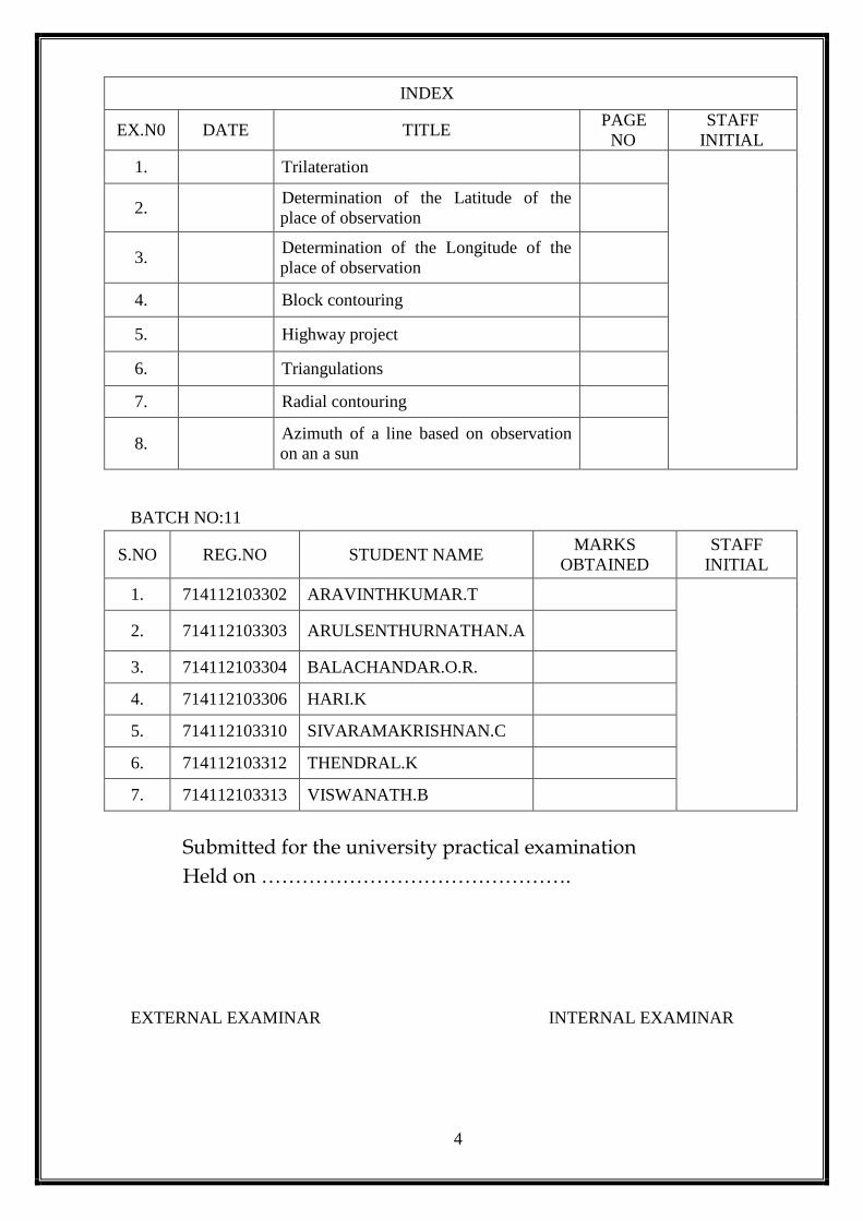
INDEX
EX.N0 DATE TITLE PAGE
NO
STAFF
INITIAL
1. Trilateration
2. Determination of the Latitude of the
place of observation
3. Determination of the Longitude of the
place of observation
4. Block contouring
5. Highway project
6. Triangulations
7. Radial contouring
8. Azimuth of a line based on observation
on an a sun
BATCH NO:11
S.NO REG.NO STUDENT NAME MARKS
OBTAINED
STAFF
INITIAL
1. 714112103302 ARAVINTHKUMAR.T
2. 714112103303 ARULSENTHURNATHAN.A
3. 714112103304 BALACHANDAR.O.R.
4. 714112103306 HARI.K
5. 714112103310 SIVARAMAKRISHNAN.C
6. 714112103312 THENDRAL.K
7. 714112103313 VISWANATH.B
Submitted for the university practical examination
Held on ……………………………………….
EXTERNAL EXAMINAR INTERNAL EXAMINAR
5
INTRODUCTION
GENERAL:
The survey camp of 2014-2015 was organized by S.G.I.T CAMPUS for the sixth
semester civil engineering students, 66 in number. The duration of the camp was ten days
from 15/12/2014 to 24/12/2014 the places in and around the Rathnagiri Murugan Temple
were chosen for surveying.
OBJECTIVES AND SCOPE OF CAMP WORKS:
The objectives of the camp works are,
To train the students in taking field observations pertaining to some of the real
world problems such as triangulation, contouring,etc..,
To train the students in all the related calculations and in the preparation of the
required maps.
The scope of the camp works may be briefly outlined as follows:
To determine the co ordinates of few triangulation stations.
To determine the co ordinates of few stations by trilateration method.
To determine the latitude of the place of observation by taking extra meridian
observation on the sun.
To determine the longitude of the place of observation by taking extra meridian
observation on the sun.
To align a highway and to calculate the earthwork involved by determining the
cross section of the highway at various intervals.
To prepare the contour map of an area by block contouring method.
To prepare the contour map of a hilly terrain by radial contouring method.

6
INSTRUCTIONS
INTRODUCTION:
This manual is intended to guide you through several survey works during survey camp.
Because of the nature of the work, you may have to say in the camp director. All students
everyday to the camp site as planned and arranged by the camp director. All students must
start to the camp site from one place which also will be informed by the camp director/HOD.
Read this manual as well as text books before commencing your work at the field. Being
prepared will help you to finish the field work early. You may require to perform calculations
after regular camp hours. Anticipate and adapt to any unexpected bad weather etc.
All reading must be noted using pen. Pencil should not be used in the field book except
drawing sketch or diagram if needed. Each batch must submit the field book to the camp
director/staff in charge for your batch. At the end of the survey camp, a survey report must be
submitted by each student which is considered to be an engineering technical report. Consider
this manual as only a guideline for preparing the survey report. Students are strictly advised
not to copy the wording, procedure, results, and conclusions given in this manual. As such,
you will be evaluated on your ability to clearly communicate your methodology, results, and
ideas to others. All charts, plots and drawings should be original.
SAFETY:
Safety is our prime concern at all times. If your conduct is deemed to compromise
safety regulations, you may be asked to leave camp and disciplinary action will be taken. Do
not perform unauthorized experiments by yourself. Never leave the survey equipments
unattended in the field. There must be no fooling around in the camp site. The students are
strictly advised to wear shoes during the entire hours of the camp as a measure of safety.
BHATCHES:
The readings are to be done by the batch as grouped by the camp director/HOD and
report should be submitted by each student. Team work is also an important aspect of this
course and it will enhance your performance.
7
FIELD WORK SCHEDULE:
The students must come prepared for their sessions to complete the field work as
scheduled.
PRACTICE: Precautions To Be Observed In The Field Work (Do’s and Don’ts):
Do’s:
1. Students must follow the instructions given by the camp director/staff
incharge.
2. Students must adhere to the dress code for the survey camp.
3. Students must handle the instruments with at most care as instructed.
4. Instruments, accessories must be properly disassembled and handed over to
the lab assistant.
Don’ts:
1. Instruments, ranging rods, pegs, arrow, staves etc have to be used only for
field work purposes. Inappropriate use of the above such accessories will
lead to disciplinary action/penalty.
2. Instruments must not be operated in a rough/violent manner.
NO MAKE-UPS:
Students must participate in the camp for all days as scheduled. Camp will not be
arranged for the students who miss it.
INTERNAL ASSESMENT MARKS:
Internal assessment will be performed as per the rules of the university.
8
CONTENTS
1. TRILATERATION
1.1 Introduction 14
1.2 Base Line 14
1.2.1 Selection of Site for Base Line 14
1.3 Stations 14
1.4 Instruments Used 15
1.5 Routine of Trilateration 15
1.6 Reconnaissance 15
1.7 Erection of Signals and Towers 15
1.8 Measurement of Length of the Sides 16
1.9 Checking the Length of the Sides 16
1.10 Astronomical Observations at Laplace Stations 17
1.11 (A) – Observations Using Subtense Bar 18
1.11 (B) - Observation Using Theodolite 18
1.12 Field Measurements 19
1.13 Calculations 19
1.14 Area Calculation 22
1.15 Results 23
1.16 Conclusion 24
2. DETERMINATION OF THE LATITUDE OF THE PLACE OF
OBSERVATION
2.1 Aim 26
2.2 Triangulation 26
2.3 Methods Adopted 26
2.3.1 Triangulation Method 26
2.3.2 Base Line Measurement 27
2.3.3 Selection Of Site 27
2.4 Apparatus Required 27
2.4.1 Invar Tape 27
2.4.2 Other Instruments Used 28
2.5 Advantages 28

9
2.6 Procedure 28
2.7 Corrections 29
2.7.1 Correction For Temperature 29
2.7.2 Correction For Pull 29
2.7.3 Correction For Sag 29
2.7.4 Correction For Tape 29
2.7.5 Standard Values 30
2.8 Observation & Tabulation 30
2.9 Calculations 31
2.9.1 Base Line Of AB Station 31
2.9.2 Vertical Distance Of AB 31
2.9.3 To Find Out Distance Of Sides 31
2.9.4 Area Calculation 35
2.9.5 To Find Intermediate Distance Of Points 38
2.9.6 To Find Out Vertical Distance Of Points 40
2.9.7 Determine The Reduce Level Of Points 41
2.9.8 Determine The Latitude Of Points 42
2.10 Result 46
2.11 Conclusion 46
3. DETERMINATION OF THE LONGITUDE OF THE PLACE OF
OBSERVATION
3.1 Aim 48
3.2 Triangulation 48
3.3 Methods Adopted 48
3.3.1 Triangulation Method 48
3.3.2 Base Line Measurement 49
3.3.3 Selection Of Site 49
3.4 Apparatus Required 49
3.4.1 Invar Tape 49
3.4.2 Other Instruments Used 50
3.5 Advantages 50
3.6 Procedure 50
3.7 Corrections 51
3.7.1 Correction For Temperature 51

10
3.7.2 Correction For Pull 51
3.7.3 Correction For Sag 51
3.7.4 Correction For Tape 51
3.7.5 Standard Values 52
3.8 Observation & Tabulation 52
3.9 Calculations 53
3.9.1 Base Line Of AB Station 53
3.9.2 Vertical Distance Of AB 53
3.9.3 To Find Out Distance Of Sides 53
3.9.4 Area Calculation 57
3.9.5 To Find Intermediate Distance Of Points 60
3.9.6 To Find Out Vertical Distance Of Points 62
3.9.7 Determine The Reduce Level Of Points 63
3.9.8 Determine The Longitude Of Points 64
3.10 Result 68
3.11 Conclusion 68
4. BLOCK CONTOURING
4.1 Introduction 70
4.2 Instruments Used 70
4.3 Reconnaissance 70
4.4 Procedure 70
4.5 Observation & Tabulation 72
4.6 Result 74
4.7 Conclusion 74
5. HIGHWAY PROJECT
5.1 Introduction 76
5.2 Instruments Used 76
5.3 Reconnaissance 76
5.4 Procedure 76
5.5 Observation and Tabulation 77
5.7 Result 100
5.8 Conclusion 100
11
6. TRIANGULATION
6.1 Introduction 102
6.2 Baseline 102
6.2.1 Selection of Site for Baseline 102
6.3 Triangulation Station 102
6.4 Instruments Used 103
6.5 Routine of Triangulation Survey 103
6.6 Reconnaissance 103
6.7 Erection of Signals and Towers 104
6.8 Measurement of Base Lines 104
6.9 Measurement of Horizontal Angles 104
6.10 Astronomical Observations at Place Stations 105
6.11 Observation & Tabulation 106
6.12 Calculations 107
6.13 Results 114
6.14 Conclusion 115
7. RADIAL CONTOURING
7.1 Introduction 117
7.2 Instruments Used 117
7.3 Reconnaissance 117
7.4 Procedure 117
7.5 Observation & Tabulation 119
7.6 Result 122
7.7 Conclusion 122
8. DETERMINATION OF THE AZIMUTH OF A SURVEY LINE BY
OBSERVATION ON THE SUN
8.1 Aim 124
8.2 Apparatus Required 124
8.3 Procedure 124
8.4 Observation & Tabulation 125
8.5 Calculations 126
8.6 Result 127

12
LIST OF TABLES
TABLE 1.1 - FROM C BLOCK TO A BLOCK 18
TABLE 1.2 - FROM A BLOCK TO C BLOCK 18
TABLE 1.3 - TRILATERATION AT STATION A&B 18
TABLE 1.4 - TRILATERATION RESULT 23
TABLE 2.1 - LAITUDE OF THE PLACE OF OBSERVATION READINGS 30
TABLE 2.2 - LAITUDE OF THE PLACE OF OBSERVATION RESULT 46
TABLE 3.1 - LONGITUDE OF THE PLACE OF OBSERVATION READINGS 52
TABLE 3.2 - LONGITUDE OF THE PLACE OF OBSERVATION RESULT 68
TABLE 4.0 - BLOCK CONTOURING 72
TABLE 5.1 - CROSS-SECTION 77
TABLE 5.2 - LONGITUDINAL SECTION 94
TABLE 6.1 - TRIANGULATION READINGS 106
TABLE 6.2 - TRIANGULATION RESULT 114
TABLE 7.0 - RADIAL CONTOURING 119
TABLE 8.0 - THE AZIMUTH OF A SURVEY LINE BY OBSERVATION ON THE SUN 124

13
1. TRILATERATION

14
EX. NO:
DATE:
1. TRILATERATION
1.1 INTRODUCTION:
Trilateration is a method of calculating the distance between the station points of a
closed traverse. The trilateration work was carried out in the S.G.I.T.campus. In this method,
the lengths of the sides and diagonals of the quadrilaterals are measured and then the
necessary correction are made.
1.2 BASE LINE:
The measurement of base line forms the most important part of the triangulation
operations. The base line is laid down with great accuracy of measurement and alignment as
it forms the basis for the computations of triangulation system.
1.2.1 Selection of Site for Base Line:
Since the accuracy in the measurement of the baseline depends upon the site
conditions, the following points be taken into consideration while selecting the site:
The site should be fairly level.
The site should free from obstructions through the whole of the length.
The extremities of the base should be intervisible at ground level.
The ground should be reasonably firm and smooth.
The site should extension to primary triangulation.
1.3 STATIONS:
The selection of stations is based upon the following considerations:
The trilateration station should be intervisible. For this purpose, they should be placed
upon the most elevated ground.
They should from well shaped triangles. No angles should be smaller than 30° or
greater than 120°.
The stations should be easily accessible.
They should be so selected that the length of sight is neither too small nor too large.
They should be in commanding situation.

15
1.4 INSTRUMENTS USED:
1. Theodolite
2. Ranging rods
3. 30m chain
4. Subtense Bar
1.5 ROUTINE OF TRILATERATION SURVEY:
The routine of survey generally consists of the following operations:
Reconnaissance
Erection of signals and towers
Measurement of length of the sides
Checking of length of the sides
Astronomical observations at laplace stations, and
Computations
1.6 RECONNAISSANCE:
Trilateration was carried out in the S.G.I.T.campus. Reconnaissance survey at the site
was done before starting the work. The area was grassy with some short herbs. There was no
obstruction to the survey work. Food, instruments, transportation was also easier as it was
within our college campus.
1.7 ERECTION OF SIGNALS AND TOWERS:
A signal is a device erected to define the exact position of an observed station. Day
light or non luminous signal i.e., flags tied to posts (ranging rods),are used as signals
at the different four stations.
A tower is a structure erected over a station for the support of the instrument and
observing party and is provided when the station or the signal or both to be elevated.
Since the survey is done on temporary stations a rigid, smooth and flat surface is
selected and the instrument and observing party are setup over that and the
observations are taken.
16
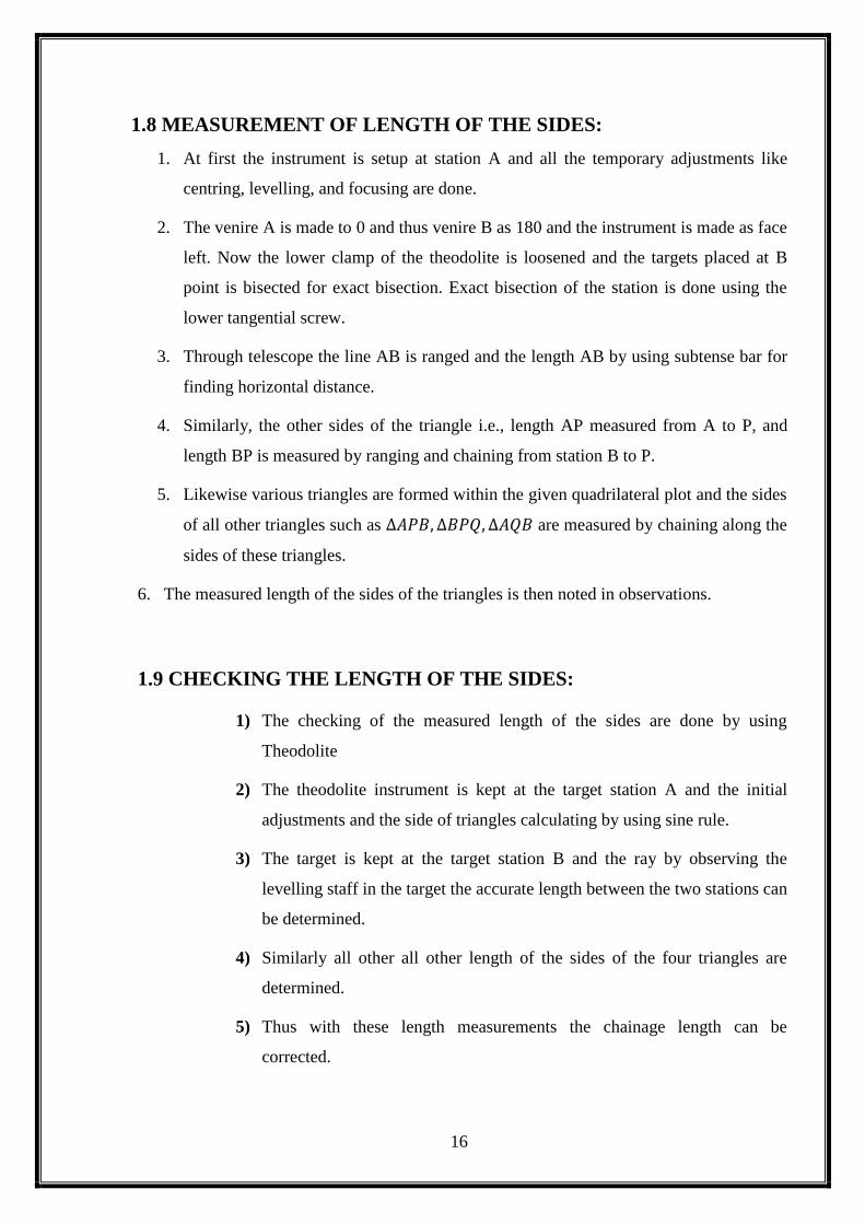
1.8 MEASUREMENT OF LENGTH OF THE SIDES:
1. At first the instrument is setup at station A and all the temporary adjustments like
centring, levelling, and focusing are done.
2. The venire A is made to 0 and thus venire B as 180 and the instrument is made as face
left. Now the lower clamp of the theodolite is loosened and the targets placed at B
point is bisected for exact bisection. Exact bisection of the station is done using the
lower tangential screw.
3. Through telescope the line AB is ranged and the length AB by using subtense bar for
finding horizontal distance.
4. Similarly, the other sides of the triangle i.e., length AP measured from A to P, and
length BP is measured by ranging and chaining from station B to P.
5. Likewise various triangles are formed within the given quadrilateral plot and the sides
of all other triangles such as ∆𝐴𝑃𝐵, ∆𝐵𝑃𝑄, ∆𝐴𝑄𝐵 are measured by chaining along the
sides of these triangles.
6. The measured length of the sides of the triangles is then noted in observations.
1.9 CHECKING THE LENGTH OF THE SIDES:
1) The checking of the measured length of the sides are done by using
Theodolite
2) The theodolite instrument is kept at the target station A and the initial
adjustments and the side of triangles calculating by using sine rule.
3) The target is kept at the target station B and the ray by observing the
levelling staff in the target the accurate length between the two stations can
be determined.
4) Similarly all other all other length of the sides of the four triangles are
determined.
5) Thus with these length measurements the chainage length can be
corrected.

17
1.10 ASTRONOMICAL OBSERVATIONS AT LAPLACE STATIONS:
1. Setup the theodolite and perform all the three temporary adjustments.
2. Set venire A to read O tight upper clamp
3. Keep face left and direct the telescope, bisect the ranging rod at P
4. Now tighter the lower clamp and release the upper lamp
5. Swing the telescope and bring the image of the sun to the I-quadrant of the cross hair
6. For making the vertical and horizontal hair tangential to the image of the sun, use the
upper clamp and vertical circle clamp. Immediately note down the time, horizontal
angle and vertical angle.
7. Change the face and release the upper clamp and vertical circle clamp and being the
image of the sun to the III quadrant, making the horizontal and vertical hairs
tangential to the image. Immediately note down the time, vertical angle and horizontal
circle reading.
8. Average of the concerned two values gives that value corresponding to the sun.

18
1.11 (A) - OBSERVATION USING SUBTENSE BAR:
TABLE – 1.1 FROM C BLOCK TO A BLOCK
FACE SIGHT TO
HORIZONTAL ANGLE MEAN
VERNIER A VERNIER B
0° 0' 0'' 0° 0' 0'' 0° 0' 0''
LEFT
ALIDADE 0 0 0 0 0 0 0 0 0
LEFT END 0 0 0 0 0 0 0 0 0
RIGHT END 1 57 20 1 54 40 1 56 0
RIGHT
ALIDADE 0 0 0 0 0 0 0 0 0
LEFT END 0 0 0 0 0 0 0 0 0
RIGHT END 1 55 0 1 57 20 1 56 10
MEAN= 1 56 5
TABLE – 1.2 FROM A BLOCK TO C BLOCK
FACE SIGHT TO
HORIZONTAL ANGLE MEAN
VERNIER A VERNIER B
0° 0' 0'' 0° 0' 0'' 0° 0' 0''
LEFT
ALIDADE 0 0 0 0 0 0 0 0 0
LEFT END 0 0 0 0 0 0 0 0 0
RIGHT END 1 55 40 1 56 40 1 56 10
RIGHT
ALIDADE 0 0 0 0 0 0 0 0 0
LEFT END 0 0 0 0 0 0 0 0 0
RIGHT END 1 56 0 1 56 0 1 56 0
MEAN= 1 56 5
1.11 (B) - OBSERVATION USING THEOOLITE:
TABLE - 1.3 TRILATERATION AT STATION A&B
STATION POINT STADIA
READING
HORIZONTAL
ANGLE
VERTICAL
ANGLE REMARK
0º 0’ 0” 0º 0’ 0”
A
P
1.555
0 0 0 1 22 0 Red tower
Q 68 5 0 1 56 20 Temple Tower
B 112 1 30 4 21 30 Station Point
B
A
1.395
0 0 0 4 22 0 Station Point
P 62 2 35 1 23 35 Red tower
Q 122 4 0 2 4 0 Temple Tower
19
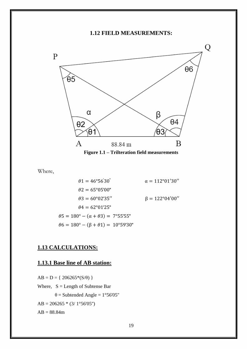
1.12 FIELD MEASUREMENTS:
Figure 1.1 – Trilteration field measurements
Where,
𝜃1 = 46°56′30′′ α = 112°01′30′′
𝜃2 = 65°05′00′′
𝜃3 = 60°02′35′′ β = 122°04′00′′
𝜃4 = 62°01′25′′
𝜃5 = 180° − (α + 𝜃3) = 7°55′55′′
𝜃6 = 180° − (β + 𝜃1) = 10°59′30′′
1.13 CALCULATIONS:
1.13.1 Base line of AB station:
AB = D = { 206265*(S/θ) }
Where, S = Length of Subtense Bar
θ = Subtended Angle = 1°56'05''
AB = 206265 * (3/ 1°56'05'')
AB = 88.84m

20
1.13.2 To find out distance of side:
i)< 𝐀𝐏𝐁
Θ5= 7°55’55’’
Θ3= 60°02’35’’
α= 112°01’30’’
To calculate the Distance of AP:
𝐴𝐵
𝑠𝑖𝑛θ5=
𝐴𝑃
𝑠𝑖𝑛θ3=
𝐵𝑃
𝑠𝑖𝑛𝛼
𝐴𝐵
𝑠𝑖𝑛θ5=
𝐴𝑃
𝑠𝑖𝑛θ3
AP =88.84
sin(7°55’55”)𝑋𝑠𝑖𝑛(60°02’35”)
AP = 577.77 m
To calculate the Distance of BP:
𝐴𝑃
𝑠𝑖𝑛θ3=
𝐵𝑃
𝑠𝑖𝑛𝛼
BP = 88.84
sin (7°55’55”)𝑋𝑠𝑖𝑛(112°01’30”)
BP = 596.80 m
ii)< 𝐀𝐐𝐁
Θ1 = 46°56’30’’
Θ6 = 10°59’30’’
β= 122°04’00’’
21
To calculate the Distance of BQ:
𝐴𝐵
𝑠𝑖𝑛θ6=
𝐵𝑄
𝑠𝑖𝑛θ1=
𝐴𝑄
𝑠𝑖𝑛𝛽
𝐴𝐵
𝑠𝑖𝑛θ6=
𝐵𝑄
𝑠𝑖𝑛θ1
BQ =88.84
sin (10°59’30”)𝑋𝑠𝑖𝑛(46°56’30”)
BQ = 340.45 m
To calculate the Distance of AQ:
𝐴𝐵
𝑠𝑖𝑛θ6=
𝐴𝑄
𝑠𝑖𝑛𝛽
AQ= 88.84
sin (10°59’30”)𝑋𝑠𝑖𝑛(122°04’00”)
AQ = 394.86 m
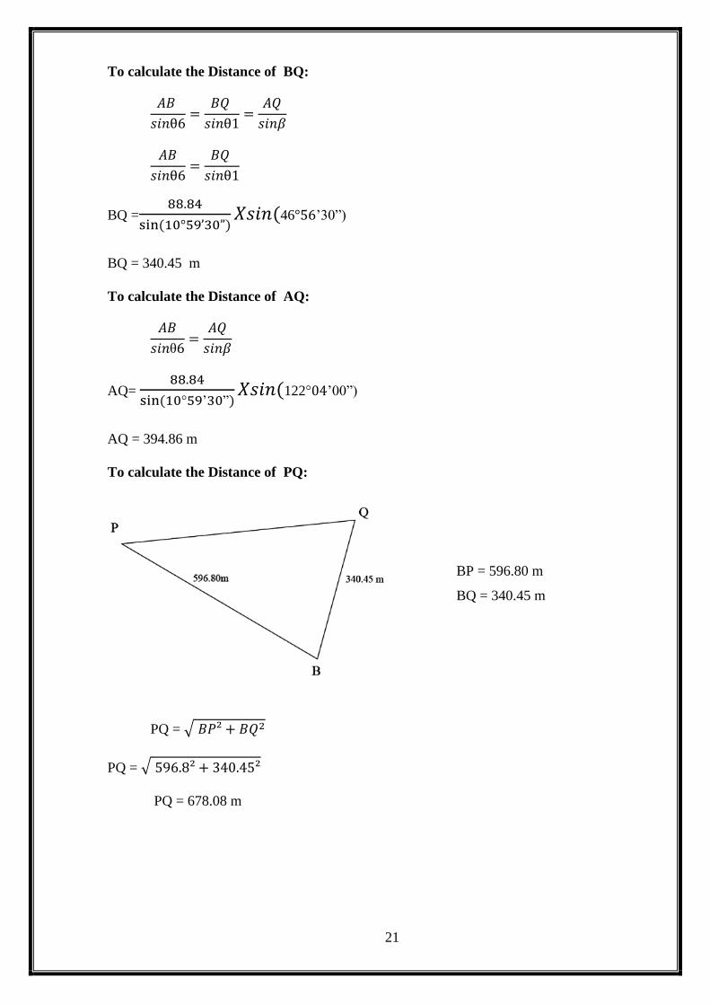
To calculate the Distance of PQ:
BP = 596.80 m
BQ = 340.45 m
PQ = √ 𝐵𝑃² + 𝐵𝑄2
PQ = √ 596.8² + 340.45²
PQ = 678.08 m
22
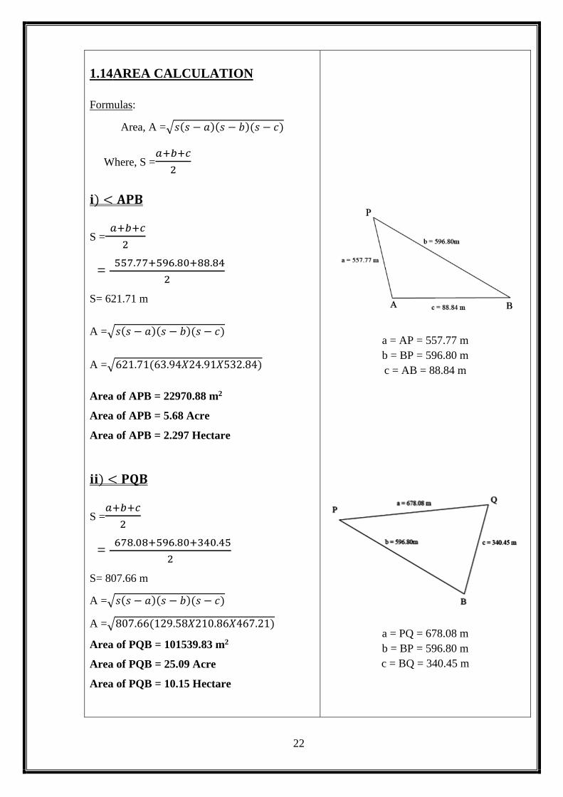
1.14AREA CALCULATION
Formulas:
Area, A =√𝑠(𝑠 − 𝑎)(𝑠 − 𝑏)(𝑠 − 𝑐)
Where, S =𝑎+𝑏+𝑐
2
𝐢) < 𝐀𝐏𝐁
S = 𝑎+𝑏+𝑐
2
= 557.77+596.80+88.84
2
S= 621.71 m
A =√𝑠(𝑠 − 𝑎)(𝑠 − 𝑏)(𝑠 − 𝑐)
A =√621.71(63.94𝑋24.91𝑋532.84)
Area of APB = 22970.88 m2
Area of APB = 5.68 Acre
Area of APB = 2.297 Hectare
𝐢𝐢) < 𝐏𝐐𝐁
S =𝑎+𝑏+𝑐
2
= 678.08+596.80+340.45
2
S= 807.66 m
A =√𝑠(𝑠 − 𝑎)(𝑠 − 𝑏)(𝑠 − 𝑐)
A =√807.66(129.58𝑋210.86𝑋467.21)
Area of PQB = 101539.83 m2
Area of PQB = 25.09 Acre
Area of PQB = 10.15 Hectare
a = AP = 557.77 m
b = BP = 596.80 m
c = AB = 88.84 m
a = PQ = 678.08 m
b = BP = 596.80 m
c = BQ = 340.45 m
23
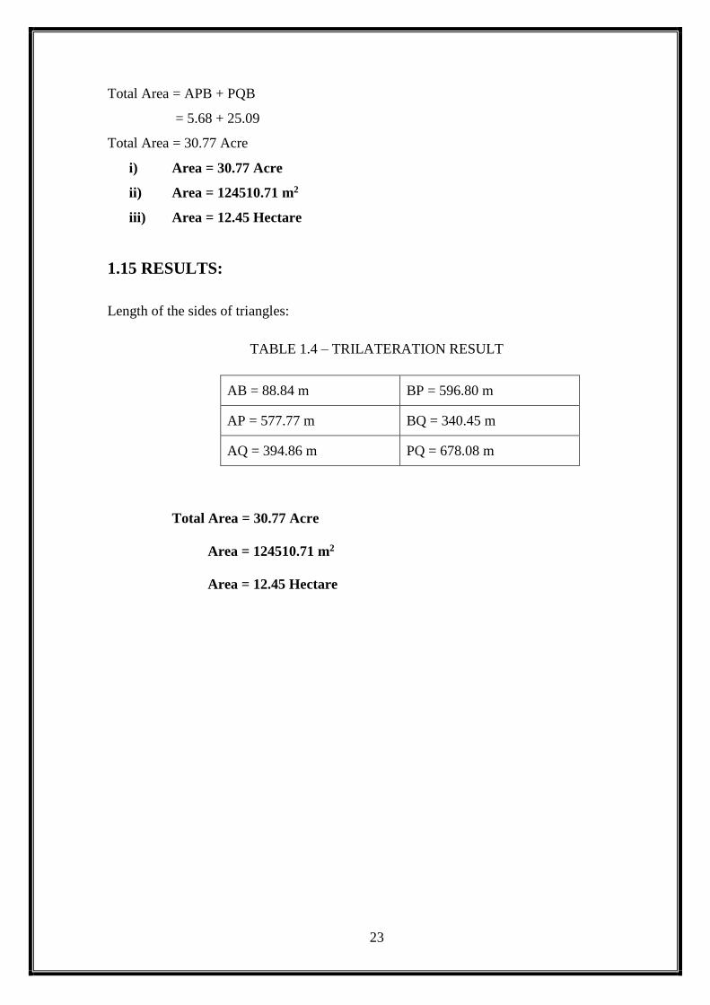
Total Area = APB + PQB
= 5.68 + 25.09
Total Area = 30.77 Acre
i) Area = 30.77 Acre
ii) Area = 124510.71 m2
iii) Area = 12.45 Hectare
1.15 RESULTS:
Length of the sides of triangles:
TABLE 1.4 – TRILATERATION RESULT
AB = 88.84 m BP = 596.80 m
AP = 577.77 m BQ = 340.45 m
AQ = 394.86 m PQ = 678.08 m
Total Area = 30.77 Acre
Area = 124510.71 m2
Area = 12.45 Hectare
24
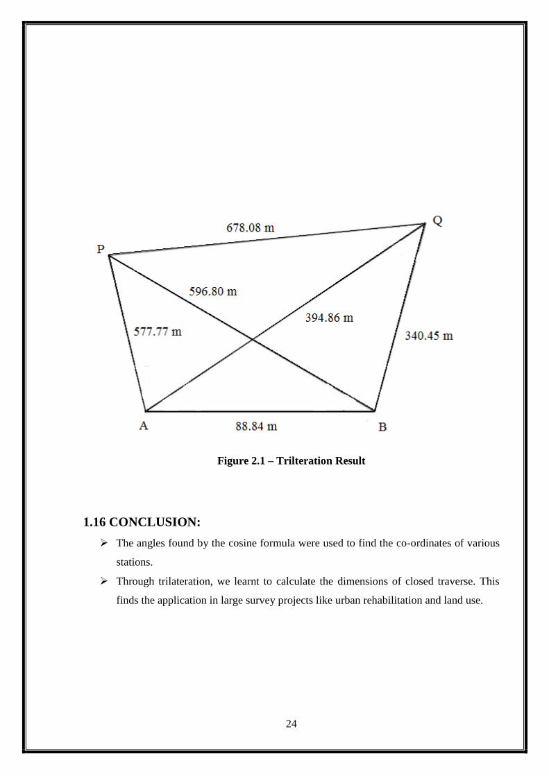
Figure 2.1 – Trilteration Result
1.16 CONCLUSION:
The angles found by the cosine formula were used to find the co-ordinates of various
stations.
Through trilateration, we learnt to calculate the dimensions of closed traverse. This
finds the application in large survey projects like urban rehabilitation and land use.

25
2. DETERMINATION OF
THE LATITUDE OF THE
PLACE OF
OBSERVATION

26
EX. NO:
DATE:
2. DETERMINATION OF THE LATITUDE OF THE PLACE
OF OBSERVATION
2.1 AIM:
The aim of geodetic survey is to establish a certain number of points on the surface whose
relative positions and elevations are determined. The positions of these points are determined
relatively in terms of length and zenith of line joining them absolutely in terms of the co
ordinate latitudes and elevation of sea level. These points serve as control points with
reference to which other ordinary topographic survey may be carried out. Hence it is more
accurate the control points wherein primarily angles are measured and the sides connecting
the points are computed with reference to choose accurate base line.
2.2 TRIANGULATION:
The horizontal control in geodetic survey is established either by triangulation system
consists of number of inter connected triangles in which the length of only one line a/called
the base lines and the angles of the triangles are measured very precisely. Knowing the length
of one side and the three angles, the length of other two sides of each triangle is computed.
The apex of the triangle is called the triangulation station. The main advantage of
triangulation is that it tends to accumulation of errors subsidiary bases are also selected.
2.3 METHODS ADOPTED:
2.3.1 TRIANGULATION METHOD:
The routine of triangulation survey generally consists of the following operations:
1. Reconnaissance
2. Erection of signals and towers
3. Measurement of base line
4. Measurement of horizontal angle
5. Astronomical observations
6. computations

27
2.3.2BASE LINE MEASUREMENT:
The measurement of base line forms the most important part of the triangulations.
The base line is laid with great accuracy of measurement and alignment at it terms the basis
for the computation of triangulation system.
2.3.3 SELECTION OF SITE:
1. The site should be fairly level. In shopping grounds, the slopes should be
uniform and gentle.
2. The site should be free from obstructions.
3. The extremities of the base should be inter visible.
4. The ground should be firm and smooth.
2.4 APPARATUS REQUIRED:
Forms of base measuring apparatus:
There are two forms:
1. Rigid bars
2. Flexible apparatus
o Rigid bars:
1. Contact apparatus
2. Optical apparatus
o Flexible apparatus:
The flexible apparatus consists of,
1. Steel invar tape
2. Steel and brass wires
2.4.1 INVAR TAPE:
Invar is steel alloy consists of 30% of nickel. It is least expansible steel alloy the co
efficient of thermal expansion is the lowest of all the known metals and alloys.
The main advantage of this tape is that it undergoes some secular change in its
length which increases slowly with time. It is softer than steel and should be handled
carefully. They are available in length of 30 to 100m with 6mm wide. They are
usually divided into mm to length of 10cm each end.
1. Three standardized tapes one for fixed measurement and the other two for
standardizing the fixed tape.
2. Straining device, making tripods supporting tripods.
28
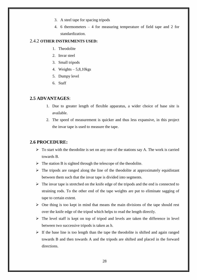
3. A steel tape for spacing tripods
4. 6 thermometers – 4 for measuring temperature of field tape and 2 for
standardization.
2.4.2 OTHER INSTRUMENTS USED:
1. Theodolite
2. Invar steel
3. Small tripods
4. Weights – 5,8,10kgs
5. Dumpy level
6. Staff
2.5 ADVANTAGES:
1. Due to greater length of flexible apparatus, a wider choice of base site is
available.
2. The speed of measurement is quicker and thus less expansive, in this project
the invar tape is used to measure the tape.
2.6 PROCEDURE:
To start with the theodolite is set on any one of the stations say A. The work is carried
towards B.
The station B is sighted through the telescope of the theodolite.
The tripods are ranged along the line of the theodolite at approximately equidistant
between them such that the invar tape is divided into segments.
The invar tape is stretched on the knife edge of the tripods and the end is connected to
straining rods. To the other end of the tape weights are put to eliminate sagging of
tape to certain extent.
One thing is too kept in mind that means the main divisions of the tape should rest
over the knife edge of the tripod which helps to read the length directly.
The level staff is kept on top of tripod and levels are taken the difference in level
between two successive tripods is taken as h.
If the base line is too length than the tape the theodolite is shifted and again ranged
towards B and then towards A and the tripods are shifted and placed in the forward
directions.

29
The absolute length of the base line is then obtained by applying corrections of
temperature, slope, sag and pull.
2.7 CORRECTIONS:
2.7.1 CORRECTION FOR TEMPERATURE:
The correction for temperature is given by Ct = ∝ (Tm – To)
Where,
A = co efficient of linear expansion
To=temperature at which the tape is standardized
Tm= temperature measured during measurement
Ct = temperature measured during measurement
2.7.2 CORRECTION FOR PULL:
Cp = (p – po) L/AE
Where,
P = Pull applied during measurement in kgs
Po = Standard pull
L = length of the tape segment
A = area of cross section of tape segment
E = modulus of elasticity in kg/cm
2.7.3 CORRECTION FOR SAG:
Cs = L(WL)^2/24P^2
Where,
L = distance between supports
W=Weight of tape per unit length
P = Pull applied in kgs
T = total length of the tape
2.7.4 CORRECTION FOR TAPE:
Cv = H^2/2L
Where,
L = span between two supports
H = difference in level between two successive pegs
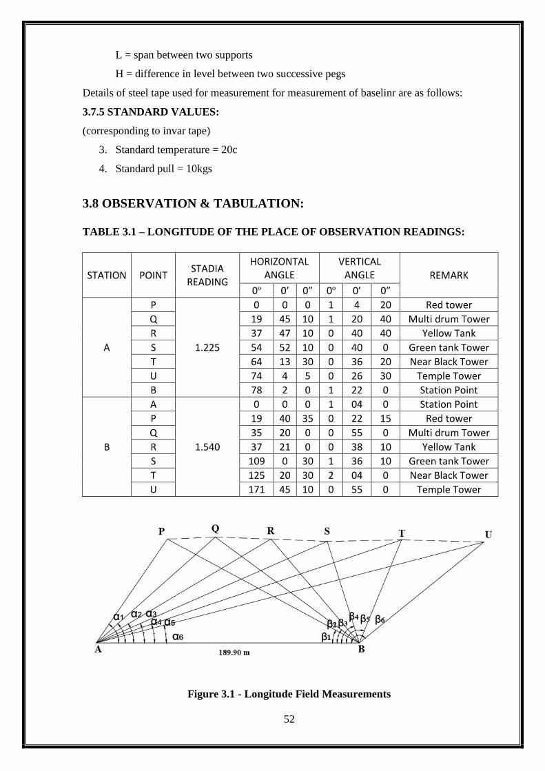
Details of steel tape used for measurement for measurement of baseline are as follows:
30
2.7.5 STANDARD VALUES:
(corresponding to invar tape)
1. Standard temperature = 20c
2. Standard pull = 10kgs
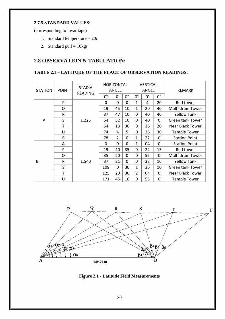
2.8 OBSERVATION & TABULATION:
TABLE 2.1 – LATITUDE OF THE PLACE OF OBSERVATION READINGS:
STATION POINT STADIA
READING
HORIZONTAL ANGLE
VERTICAL ANGLE REMARK
0º 0’ 0” 0º 0’ 0”
A
P
1.225
0 0 0 1 4 20 Red tower
Q 19 45 10 1 20 40 Multi drum Tower
R 37 47 10 0 40 40 Yellow Tank
S 54 52 10 0 40 0 Green tank Tower
T 64 13 30 0 36 20 Near Black Tower
U 74 4 5 0 26 30 Temple Tower
B 78 2 0 1 22 0 Station Point
B
A
1.540
0 0 0 1 04 0 Station Point
P 19 40 35 0 22 15 Red tower
Q 35 20 0 0 55 0 Multi drum Tower
R 37 21 0 0 38 10 Yellow Tank
S 109 0 30 1 36 10 Green tank Tower
T 125 20 30 2 04 0 Near Black Tower
U 171 45 10 0 55 0 Temple Tower
Figure 2.1 - Latitude Field Measurements
31
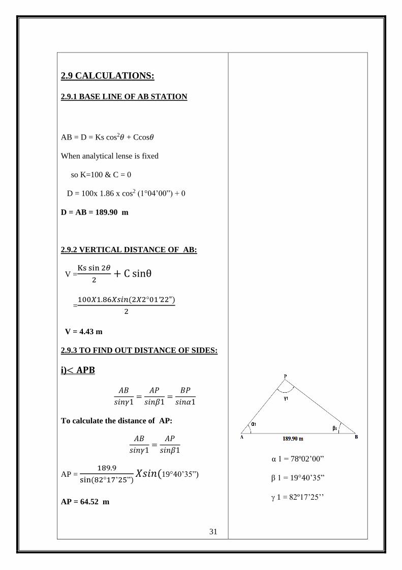
2.9 CALCULATIONS:
2.9.1 BASE LINE OF AB STATION
AB = D = Ks cos2𝜃 + Ccos𝜃
When analytical lense is fixed
so K=100 & C = 0
D = 100x 1.86 x cos2 (1°04’00”) + 0
D = AB = 189.90 m
2.9.2 VERTICAL DISTANCE OF AB:
V =Ks sin 2𝜃
2+ C sinθ
=100𝑋1.86𝑋𝑠𝑖𝑛(2𝑋2°01′22")
2
V = 4.43 m
2.9.3 TO FIND OUT DISTANCE OF SIDES:
i)< 𝐀𝐏𝐁
𝐴𝐵
𝑠𝑖𝑛𝛾1=
𝐴𝑃
𝑠𝑖𝑛𝛽1=
𝐵𝑃
𝑠𝑖𝑛𝛼1
To calculate the distance of AP:
𝐴𝐵
𝑠𝑖𝑛𝛾1=
𝐴𝑃
𝑠𝑖𝑛𝛽1
AP = 189.9
sin (82°17’25”)𝑋𝑠𝑖𝑛(19°40’35”)
AP = 64.52 m
α 1 = 78º02’00”
β 1 = 19°40’35”
1 = 82º17’25’’
32
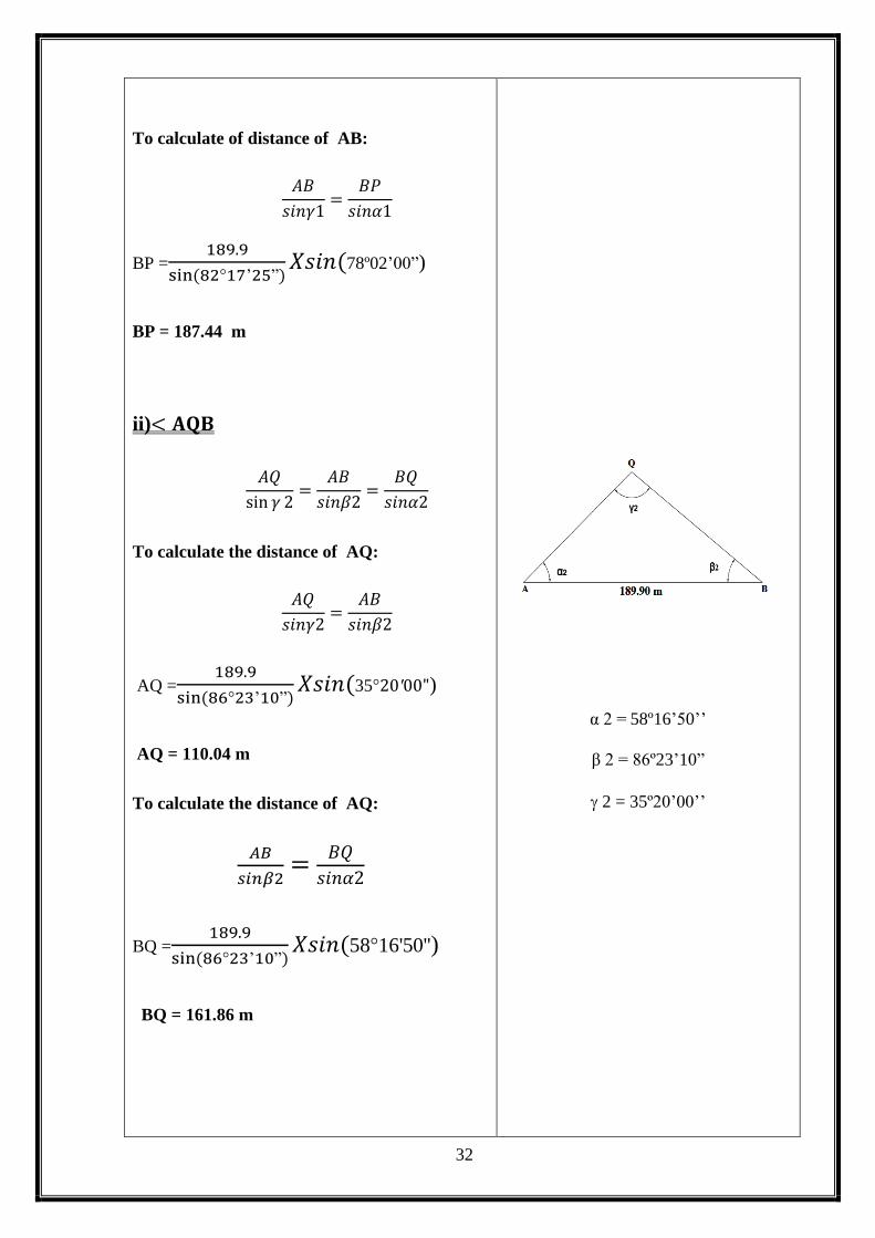
To calculate of distance of AB:
𝐴𝐵
𝑠𝑖𝑛𝛾1=
𝐵𝑃
𝑠𝑖𝑛𝛼1
BP =189.9
sin (82°17’25”)𝑋𝑠𝑖𝑛(78º02’00”)
BP = 187.44 m
ii)< 𝐀𝐐𝐁
𝐴𝑄
sin 𝛾 2=
𝐴𝐵
𝑠𝑖𝑛𝛽2=
𝐵𝑄
𝑠𝑖𝑛𝛼2
To calculate the distance of AQ:
𝐴𝑄
𝑠𝑖𝑛𝛾2=
𝐴𝐵
𝑠𝑖𝑛𝛽2
AQ =189.9
sin (86°23’10”)𝑋𝑠𝑖𝑛(35°20′00")
AQ = 110.04 m
To calculate the distance of AQ:
𝐴𝐵
𝑠𝑖𝑛𝛽2=
𝐵𝑄
𝑠𝑖𝑛𝛼2
BQ =189.9
sin (86°23’10”)𝑋𝑠𝑖𝑛(58°16'50'')
BQ = 161.86 m
α 2 = 58º16’50’’
β 2 = 86º23’10”
2 = 35º20’00’’
33
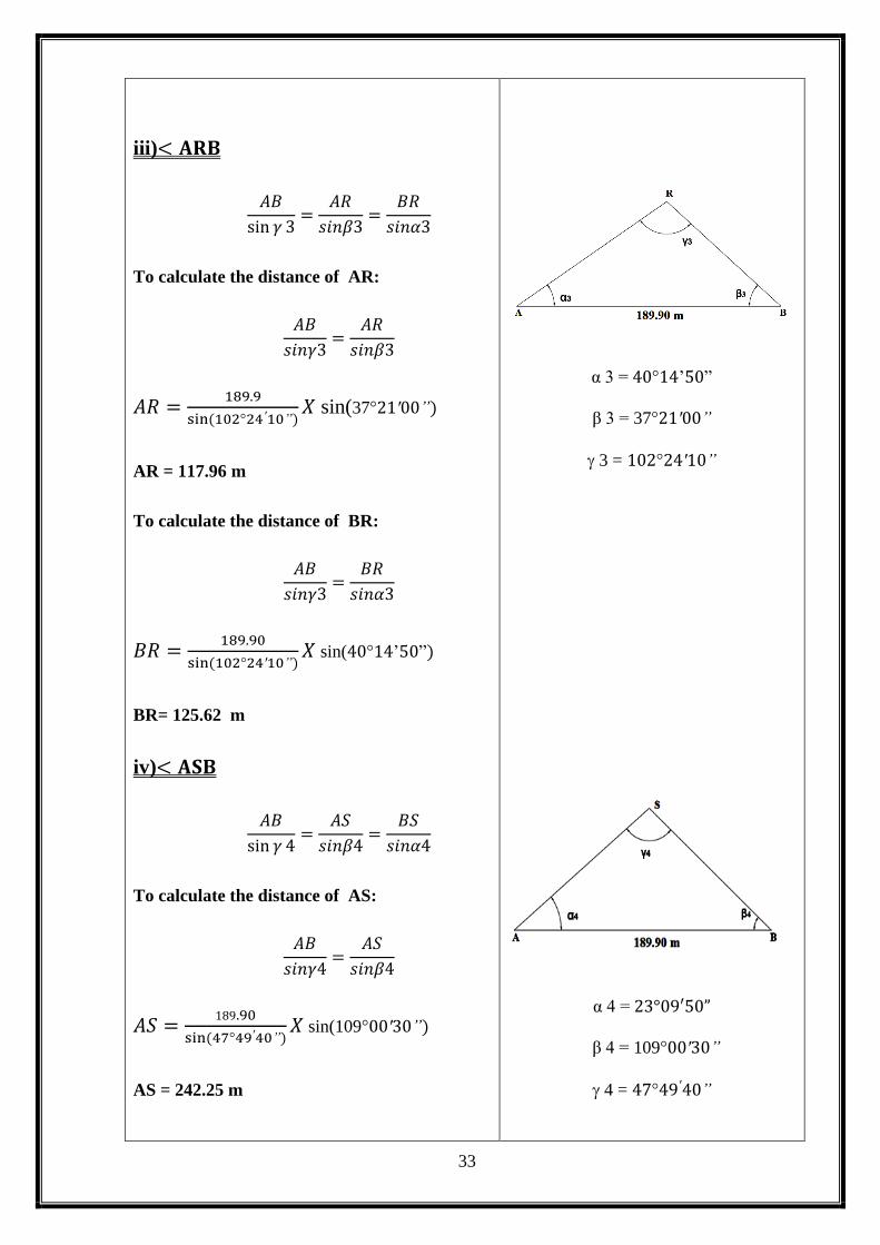
iii)< 𝐀𝐑𝐁
𝐴𝐵
sin 𝛾 3=
𝐴𝑅
𝑠𝑖𝑛𝛽3=
𝐵𝑅
𝑠𝑖𝑛𝛼3
To calculate the distance of AR:
𝐴𝐵
𝑠𝑖𝑛𝛾3=
𝐴𝑅
𝑠𝑖𝑛𝛽3
𝐴𝑅 =189.9
sin (102°24′10”)𝑋 sin(37°21′00”)
AR = 117.96 m
To calculate the distance of BR:
𝐴𝐵
𝑠𝑖𝑛𝛾3=
𝐵𝑅
𝑠𝑖𝑛𝛼3
𝐵𝑅 =189.90
sin (102°24′10”)𝑋 sin(40°14’50”)
BR= 125.62 m
iv)< 𝐀𝐒𝐁
𝐴𝐵
sin 𝛾 4=
𝐴𝑆
𝑠𝑖𝑛𝛽4=
𝐵𝑆
𝑠𝑖𝑛𝛼4
To calculate the distance of AS:
𝐴𝐵
𝑠𝑖𝑛𝛾4=
𝐴𝑆
𝑠𝑖𝑛𝛽4
𝐴𝑆 =189.90
sin (47°49′40”)𝑋 sin(109°00′30”)
AS = 242.25 m
α 3 = 40°14’50”
β 3 = 37°21′00”
3 = 102°24′10”
α 4 = 23°09′50”
β 4 = 109°00′30”
4 = 47°49′40”
34
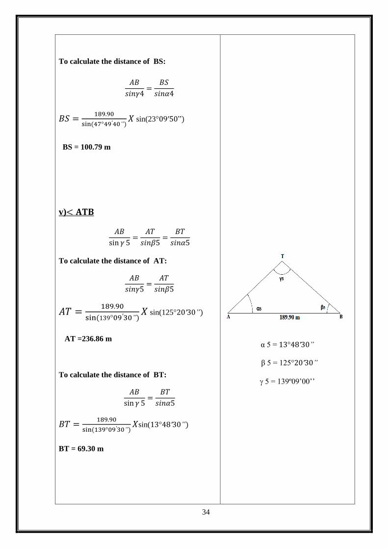
To calculate the distance of BS:
𝐴𝐵
𝑠𝑖𝑛𝛾4=
𝐵𝑆
𝑠𝑖𝑛𝛼4
𝐵𝑆 =189.90
sin (47°49′40”)𝑋 sin(23°09′50”)
BS = 100.79 m
v)< 𝐀𝐓𝐁
𝐴𝐵
sin 𝛾 5=
𝐴𝑇
𝑠𝑖𝑛𝛽5=
𝐵𝑇
𝑠𝑖𝑛𝛼5
To calculate the distance of AT:
𝐴𝐵
𝑠𝑖𝑛𝛾5=
𝐴𝑇
𝑠𝑖𝑛𝛽5
𝐴𝑇 =189.90
sin (139°09′30”)𝑋 sin(125°20′30”)
AT =236.86 m
To calculate the distance of BT:
𝐴𝐵
sin 𝛾 5=
𝐵𝑇
𝑠𝑖𝑛𝛼5
𝐵𝑇 =189.90
sin (139°09′30”)𝑋sin(13°48′30”)
BT = 69.30 m
α 5 = 13°48′30”
β 5 = 125°20′30”
5 = 139º09’00’’

35
vi)< 𝐀𝐔𝐁
𝐴𝐵
sin 𝛾 6=
𝐴𝑈
𝑠𝑖𝑛𝛽6=
𝐵𝑈
𝑠𝑖𝑛𝛼6
To calculate the distance of BU:
𝐴𝐵
sin 𝛾 6=
𝐵𝑈
𝑠𝑖𝑛𝛼6
𝐵𝑈 =189.90
sin (04°14′55”)𝑋 sin(3°57′55”)
BU = 175.87 m
To check the distance of AU:
𝐴𝐵
sin 𝛾 6=
𝐴𝑈
𝑠𝑖𝑛𝛽6
𝐴𝑈 =189.90
sin(04°16′55”)𝑋sin(171°45′10”)
AU = 364.83 m
2.9.4 AREA CALCULATION:
Formulas:
Area, A =√𝑠(𝑠 − 𝑎)(𝑠 − 𝑏)(𝑠 − 𝑐)
Where, S =a+b+c
2
𝐢) < 𝐀𝐏𝐁
S =𝑎+𝑏+𝑐
2
= 64.52+189.9+187.47
2
S= 220.945 m
α 6 = 3°57′55”
β 6 = 171º45’10’’
6 = 04°16′55”
a = AP = 64.52 m
b = AB = 189.90 m
c = BP = 187.47 m

36
A =√𝑠(𝑠 − 𝑎)(𝑠 − 𝑏)(𝑠 − 𝑐)
A =√220.495(155.975𝑋30.595𝑋33.025)
Area of APB = 5894.86 m2
Area of APB = 1.456 Acre
Area of APB = 0.589 Hectare
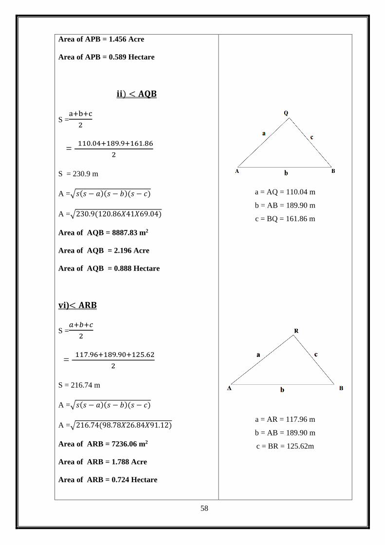
𝐢𝐢) < 𝐀𝐐𝐁
S =a+b+c
2
= 110.04+189.9+161.86
2
S = 230.9 m
A =√𝑠(𝑠 − 𝑎)(𝑠 − 𝑏)(𝑠 − 𝑐)
A =√230.9(120.86𝑋41𝑋69.04)
Area of AQB = 8887.83 m2
Area of AQB = 2.196 Acre
Area of AQB = 0.888 Hectare
𝐯𝐢)< 𝐀𝐑𝐁
S =𝑎+𝑏+𝑐
2
= 117.96+189.90+125.62
2
S = 216.74 m
A =√𝑠(𝑠 − 𝑎)(𝑠 − 𝑏)(𝑠 − 𝑐)
A =√216.74(98.78𝑋26.84𝑋91.12)
a = AQ = 110.04 m
b = AB = 189.90 m
c = BQ = 161.86 m
a = AR = 117.96 m
b = AB = 189.90 m
c = BR = 125.62m
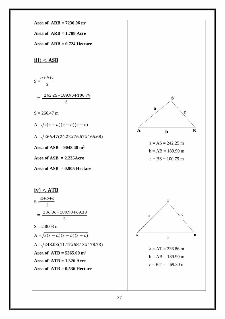
37
Area of ARB = 7236.06 m2
Area of ARB = 1.788 Acre
Area of ARB = 0.724 Hectare
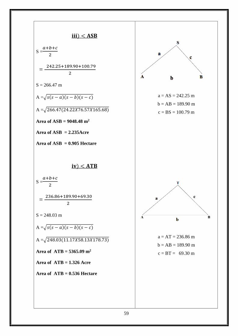
𝐢𝐢𝐢) < 𝐀𝐒𝐁
S =𝑎+𝑏+𝑐
2
= 242.25+189.90+100.79
2
S = 266.47 m
A =√𝑠(𝑠 − 𝑎)(𝑠 − 𝑏)(𝑠 − 𝑐)
A =√266.47(24.22𝑋76.57𝑋165.68)
Area of ASB = 9048.48 m2
Area of ASB = 2.235Acre
Area of ASB = 0.905 Hectare
𝐢𝐯) < 𝐀𝐓𝐁
S =𝑎+𝑏+𝑐
2
= 236.86+189.90+69.30
2
S = 248.03 m
A =√𝑠(𝑠 − 𝑎)(𝑠 − 𝑏)(𝑠 − 𝑐)
A =√248.03(11.17𝑋58.13𝑋178.73)
Area of ATB = 5365.09 m2
Area of ATB = 1.326 Acre
Area of ATB = 0.536 Hectare
a = AS = 242.25 m
b = AB = 189.90 m
c = BS = 100.79 m
a = AT = 236.86 m
b = AB = 189.90 m
c = BT = 69.30 m

38
Total Area = APB+AQB+ARB+ASB+ATB+AUB
= 1.456+2.196+1.788+2.235+1.326+0.59
Total Area = 9.591 Acre
i) Area = 9.591 Acre
ii) Area = 38820.75 m2
iii) Area = 3.882 Hectare
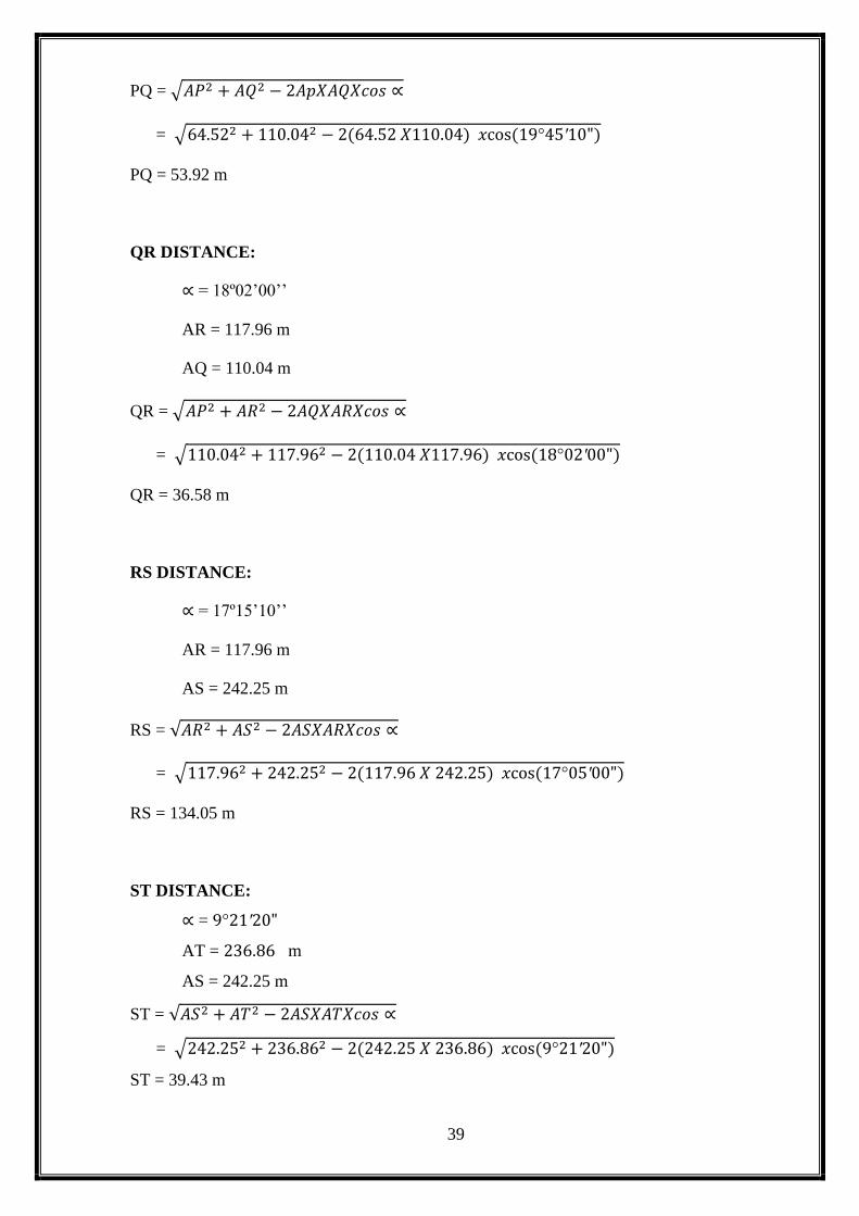
2.9.5 TO FIND INTERMEDIATE DISTANCE OF POINTS:
PQ DISTANCE:
∝ = 19º45’10’’
AP = 64.52 m
AQ = 110.04 m
𝐯) < 𝐀𝐔𝐁
S =𝑎+𝑏+𝑐
2
= 364.83+189.90+175.87
2
S = 365.30 m
A =√𝑠(𝑠 − 𝑎)(𝑠 − 𝑏)(𝑠 − 𝑐)
A =√365.30(0.47𝑋175.4𝑋189.43)
Area of SEF = 2388.43 m2
Area of SEF = 0.59Acre
Area of SEF = 0.238 Hectare
a = AU = 364.83 m
b = AB = 189.90 m
c = BU = 175.87 m
39
PQ = √𝐴𝑃2 + 𝐴𝑄2 − 2𝐴𝑝𝑋𝐴𝑄𝑋𝑐𝑜𝑠 ∝
= √64.522 + 110.042 − 2(64.52 𝑋110.04) 𝑥cos (19°45′10")
PQ = 53.92 m
QR DISTANCE:
∝ = 18º02’00’’
AR = 117.96 m
AQ = 110.04 m
QR = √𝐴𝑃2 + 𝐴𝑅2 − 2𝐴𝑄𝑋𝐴𝑅𝑋𝑐𝑜𝑠 ∝
= √110.042 + 117.962 − 2(110.04 𝑋117.96) 𝑥cos (18°02′00")
QR = 36.58 m
RS DISTANCE:
∝ = 17º15’10’’
AR = 117.96 m
AS = 242.25 m
RS = √𝐴𝑅2 + 𝐴𝑆2 − 2𝐴𝑆𝑋𝐴𝑅𝑋𝑐𝑜𝑠 ∝
= √117.962 + 242.252 − 2(117.96 𝑋 242.25) 𝑥cos (17°05′00")
RS = 134.05 m
ST DISTANCE:
∝ = 9°21′20"
AT = 236.86 m
AS = 242.25 m
ST = √𝐴𝑆2 + 𝐴𝑇2 − 2𝐴𝑆𝑋𝐴𝑇𝑋𝑐𝑜𝑠 ∝
= √242.252 + 236.862 − 2(242.25 𝑋 236.86) 𝑥cos (9°21′20")
ST = 39.43 m
40
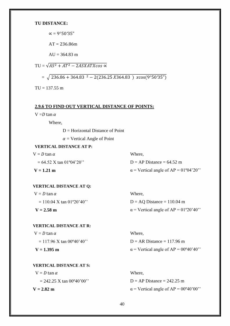
TU DISTANCE:
∝ = 9°50′35"
AT = 236.86m
AU = 364.83 m
TU = √𝐴𝑆2 + 𝐴𝑇2 − 2𝐴𝑆𝑋𝐴𝑇𝑋𝑐𝑜𝑠 ∝
= √ 236.86 + 364.83 2 − 2(236.25 𝑋364.83 ) 𝑥cos (9°50′35")
TU = 137.55 m
2.9.6 TO FIND OUT VERTICAL DISTANCE OF POINTS:
V =𝐷 tan 𝛼
Where,
D = Horizontal Distance of Point
𝛼 = Vertical Angle of Point
VERTICAL DISTANCE AT P:
V = 𝐷 tan 𝛼
= 64.52 X tan 01º04’20’’
V = 1.21 m
Where,
D = AP Distance = 64.52 m
α = Vertical angle of AP = 01º04’20’’
VERTICAL DISTANCE AT Q:
V = 𝐷 tan 𝛼
= 110.04 X tan 01º20’40’’
V = 2.58 m
Where,
D = AQ Distance = 110.04 m
α = Vertical angle of AP = 01º20’40’’
VERTICAL DISTANCE AT R:
V = 𝐷 tan 𝛼
= 117.96 X tan 00º40’40’’
V = 1.395 m
Where,
D = AR Distance = 117.96 m
α = Vertical angle of AP = 00º40’40’’
VERTICAL DISTANCE AT S:
V = 𝐷 tan 𝛼
= 242.25 X tan 00º40’00’’
V = 2.82 m
Where,
D = AP Distance = 242.25 m
α = Vertical angle of AP = 00º40’00’’

41
VERTICAL DISTANCE AT T:
V = 𝐷 tan 𝛼
= 236.86 X tan 00º36’20’’
V = 2.50 m
Where,
D = AP Distance = 236.86 m
α = Vertical angle of AP = 00º36’20’’
VERTICAL DISTANCE AT U:
V = 𝐷 tan 𝛼
= 364.83 X tan 00º26’30’’
V = 2.81 m
Where,
D = AP Distance = 364.83 m
α = Vertical angle of AP = 00º26’30’’
2.9.7 DETERMINE THE REDUCE LEVEL OF POINTS:
R.L. of bench mark = 100.00
Height of instrument = (10.67 + 1.225) = 11.895m
Reduce level of A = R.L. of BM + H.I
= 100 + 11.895
= 110.67 m
Reduce level of B = R.L. of BM + H.I + V – H2
= 100 + 11.895 + 4.43 + 1.454
= 114.785 m
Reduce level of P = R.L. of BM + H.I - V
= 100 + 11.895 + 1.21
= 110.685 m
Reduce level of Q = R.L. of BM + H.I - V
= 100 + 11.895 – 2.58
= 109.315 m
Reduce level of R= R.L. of BM + H.I - V
= 100 + 11.895 -1.395
= 110.50 m

42
Reduce level of S = R.L. of BM + H.I - V
= 100 + 11.895 – 2.82
= 109.075 m
Reduce level of T = R.L. of BM + H.I - V
= 100 + 11.895 – 2.50
= 109.395 m
Reduce level of U = R.L. of BM + H.I - V
= 100 + 11.895 – 2.81
= 109.085 m
2.9.8 DETERMINE THE LATITUDE OF POINTS:
LATITUDE AT POINT P:
Quadrant - IV
Origin - A = 0°0'00''
At point P = N 1W
Reduced Bering = N 19°45'10'' W
L = Distance of AP = 64.52 m
Latitude : (+ , - )
= L cos 1
= 64.52 X cos (19°45'10'')
= + 60.72 m
A
A

43
LATITUDE AT POINT Q:
Quadrant - IV
Origin - A = 0°0'00''
At point Q = N 2 W
Reduced Bering = N 37°47'10'' W
L = Distance of AQ = 110.04 m
Latitude : (+ , - )
= L cos 2
= 110.04 X cos (37°47'10'')
= +86.96 m
LATITUDE AT POINT R:
Quadrant - IV
Origin - A = 0°0'00''
At point Q = N 3 W
Reduced Bering = N 54°52'10'' W
Q
2
A
R
3
A
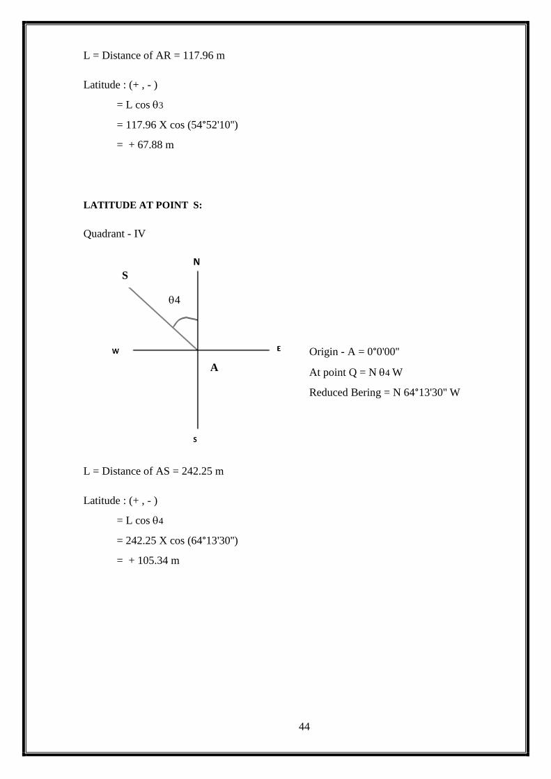
44
L = Distance of AR = 117.96 m
Latitude : (+ , - )
= L cos 3
= 117.96 X cos (54°52'10'')
= + 67.88 m
LATITUDE AT POINT S:
Quadrant - IV
Origin - A = 0°0'00''
At point Q = N 4 W
Reduced Bering = N 64°13'30'' W
L = Distance of AS = 242.25 m
Latitude : (+ , - )
= L cos 4
= 242.25 X cos (64°13'30'')
= + 105.34 m
S
4
A
45
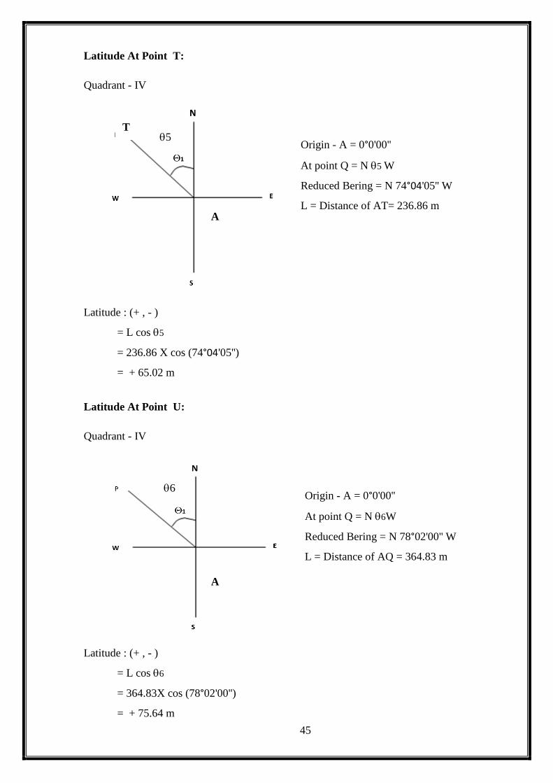
Latitude At Point T:
Quadrant - IV
Origin - A = 0°0'00''
At point Q = N 5 W
Reduced Bering = N 74°04'05'' W
L = Distance of AT= 236.86 m
Latitude : (+ , - )
= L cos 5
= 236.86 X cos (74°04'05'')
= + 65.02 m
Latitude At Point U:
Quadrant - IV
Origin - A = 0°0'00''
At point Q = N 6W
Reduced Bering = N 78°02'00'' W
L = Distance of AQ = 364.83 m
Latitude : (+ , - )
= L cos 6
= 364.83X cos (78°02'00'')
= + 75.64 m
T 5
A
U 6
A
46
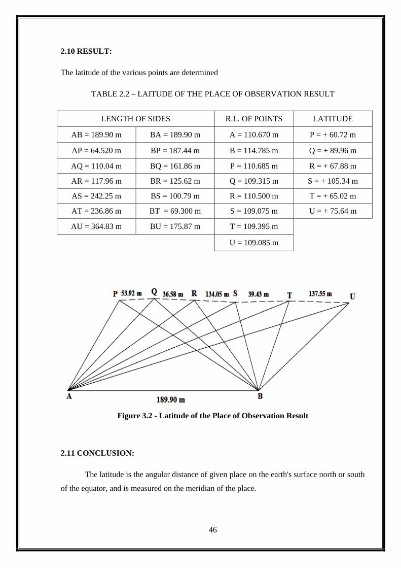
2.10 RESULT:
The latitude of the various points are determined
TABLE 2.2 – LAITUDE OF THE PLACE OF OBSERVATION RESULT
LENGTH OF SIDES R.L. OF POINTS LATITUDE
AB = 189.90 m BA = 189.90 m A = 110.670 m P = + 60.72 m
AP = 64.520 m BP = 187.44 m B = 114.785 m Q = + 89.96 m
AQ = 110.04 m BQ = 161.86 m P = 110.685 m R = + 67.88 m
AR = 117.96 m BR = 125.62 m Q = 109.315 m S = + 105.34 m
AS = 242.25 m BS = 100.79 m R = 110.500 m T = + 65.02 m
AT = 236.86 m BT = 69.300 m S = 109.075 m U = + 75.64 m
AU = 364.83 m BU = 175.87 m T = 109.395 m
U = 109.085 m
Figure 3.2 - Latitude of the Place of Observation Result
2.11 CONCLUSION:
The latitude is the angular distance of given place on the earth's surface north or south
of the equator, and is measured on the meridian of the place.

47
3. DETERMINATION OF
THE LONGITUDE OF THE
PLACE OF
OBSERVATION

48
EX. NO:
DATE:
3. DETERMINATION OF THE LONGITUDE OF THE PLACE
OF OBSERVATION
3.1 AIM:
The aim of geodetic survey is to establish a certain number of points on the surface whose
relative positions and elevations are determined. The positions of these points are determined
relatively in terms of length and zenith of line joining them absolutely in terms of the co
ordinate latitudes, longitudes and elevation of sea level. These points serve as control points
with reference to which other ordinary topographic survey may be carried out. Hence it is
more accurate the control points wherein primarily angles are measured and the sides
connecting the points are computed with reference to choose accurate base line.
3.2 TRIANGULATION:
The horizontal control in geodetic survey is established either by triangulation system
consists of number of inter connected triangles in which the length of only one line a/called
the base lines and the angles of the triangles are measured very precisely. Knowing the length
of one side and the three angles, the length of other two sides of each triangle is computed.
The apex of the triangle is called the triangulation station. The main advantage of
triangulation is that it tends to accumulation of errors subsidiary bases are also selected.
3.3 METHODS ADOPTED:
3.3.1 TRIANGULATION METHOD:
The routine of triangulation survey generally consists of the following operations:
1. Reconnaissance
2. Erection of signals and towers
3. Measurement of base line
4. Measurement of horizontal angle
5. Astronomical observations
6. computations

49
3.3.2 BASE LINE MEASUREMENT:
The measurement of base line forms the most important part of the triangulations. The base
line is laid with great accuracy of measurement and alignment at it terms the basis for the
computation of triangulation system.
3.3.3 SELECTION OF SITE:
1. The site should be fairly level. In shopping grounds, the slopes should be uniform
and gentle.
2. The site should be free from obstructions.
3. The extremities of the base should be inter visible.
4. The ground should be firm and smooth.
3.4 APPARATUS REQUIRED:
Forms of base measuring apparatus:
There are two forms:
1. Rigid bars
2. Flexible apparatus
Rigid bars:
1. Contact apparatus
2. Optical apparatus
Flexible apparatus:
The flexible apparatus consists of,
1. Steel invar tape
2. Steel and brass wires
3.4.1 INVAR TAPE:
Invar is steel alloy consists of 30% of nickel. It is least expansible steel alloy the co
efficient of thermal expansion is the lowest of all the known metals and alloys.
The main advantage of this tape is that it undergoes some secular change in its
length which increases slowly with time. It is softer than steel and should be handled
carefully. They are available in length of 30 to 100m with 6mm wide. They are
usually divided into mm to length of 10cm each end.

50
1. Three standardized tapes one for fixed measurement and the other two
for standardizing the fixed tape.
2. Straining device, making tripods supporting tripods.
3. A steel tape for spacing tripods
4. 6 thermometers – 4 for measuring temperature of field tape and 2 for
standardization.
3.4.2 OTHER INSTRUMENTS USED:
1. Theodolite
2. Invar steel
3. Small tripods
4. Weights – 5,8,10kgs
5. Dumpy level
6. Staff
3.5 ADVANTAGES:
1. Due to greater length of flexible apparatus, a wider choice of base site is
available.
2. The speed of measurement is quicker and thus less expansive, in this
project the invar tape is used to measure the tape.
3.6 PROCEDURE:
To start with the theodolite is set on any one of the stations say A. The work is carried
towards B.
The station B is sighted through the telescope of the theodolite.
The tripods are ranged along the line of the theodolite at approximately equidistant
between them such that the invar tape is divided into segments.
The invar tape is stretched on the knife edge of the tripods and the end is connected to
straining rods. To the other end of the tape weights are put to eliminate sagging of
tape to certain extent.
One thing is too kept in mind that means the main divisions of the tape should rest
over the knife edge of the tripod which helps to read the length directly.
The level staff is kept on top of tripod and levels are taken the difference in level
between two successive tripods is taken as h.
51
If the base line is too length than the tape the theodolite is shifted and again ranged
towards B and then towards A and the tripods are shifted and placed in the forward
directions.
The absolute length of the base line is then obtained by applying corrections of
temperature,slope,sag and pull.
3.7 CORRECTIONS:
3.7.1 CORRECTION FOR TEMPERATURE:
The correction for temperature is given by Ct = ∝ (Tm – To)
Where,
A = co efficient of linear expansion
To=temperature at which the tape is standardized
Tm= temperature measured during measurement
Ct = temperature measured during measurement
3.7.2 CORRECTION FOR PULL:
Cp = (p – po)L/AE
Where,
P = Pull applied during measurement in kgs
Po = Standard pull
L = length of the tape segment
A = area of cross section of tape segment
E = modulus of elasticity in kg/cm
3.7.3CORRECTION FOR SAG:
Cs = L(WL)^2/24P^2
Where,
L = distance between supports
W=Weight of tape per unit length
P = Pull applied in kgs
T = total length of the tape
3.7.4CORRECTION FOR TAPE:
Cv = H^2/2L
Where,
52
L = span between two supports
H = difference in level between two successive pegs
Details of steel tape used for measurement for measurement of baselinr are as follows:
3.7.5 STANDARD VALUES:
(corresponding to invar tape)
3. Standard temperature = 20c
4. Standard pull = 10kgs
3.8 OBSERVATION & TABULATION:
TABLE 3.1 – LONGITUDE OF THE PLACE OF OBSERVATION READINGS:
STATION POINT STADIA
READING
HORIZONTAL ANGLE
VERTICAL ANGLE REMARK
0º 0’ 0” 0º 0’ 0”
A
P
1.225
0 0 0 1 4 20 Red tower
Q 19 45 10 1 20 40 Multi drum Tower
R 37 47 10 0 40 40 Yellow Tank
S 54 52 10 0 40 0 Green tank Tower
T 64 13 30 0 36 20 Near Black Tower
U 74 4 5 0 26 30 Temple Tower
B 78 2 0 1 22 0 Station Point
B
A
1.540
0 0 0 1 04 0 Station Point
P 19 40 35 0 22 15 Red tower
Q 35 20 0 0 55 0 Multi drum Tower
R 37 21 0 0 38 10 Yellow Tank
S 109 0 30 1 36 10 Green tank Tower
T 125 20 30 2 04 0 Near Black Tower
U 171 45 10 0 55 0 Temple Tower
Figure 3.1 - Longitude Field Measurements
53
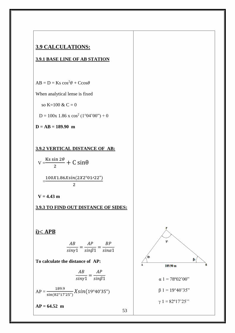
3.9 CALCULATIONS:
3.9.1 BASE LINE OF AB STATION
AB = D = Ks cos2𝜃 + Ccos𝜃
When analytical lense is fixed
so K=100 & C = 0
D = 100x 1.86 x cos2 (1°04’00”) + 0
D = AB = 189.90 m
3.9.2 VERTICAL DISTANCE OF AB:
V =Ks sin 2𝜃
2+ C sinθ
=100𝑋1.86𝑋𝑠𝑖𝑛(2𝑋2°01′22")
2
V = 4.43 m
3.9.3 TO FIND OUT DISTANCE OF SIDES:
i)< 𝐀𝐏𝐁
𝐴𝐵
𝑠𝑖𝑛𝛾1=
𝐴𝑃
𝑠𝑖𝑛𝛽1=
𝐵𝑃
𝑠𝑖𝑛𝛼1
To calculate the distance of AP:
𝐴𝐵
𝑠𝑖𝑛𝛾1=
𝐴𝑃
𝑠𝑖𝑛𝛽1
AP = 189.9
sin (82°17’25”)𝑋𝑠𝑖𝑛(19°40’35”)
AP = 64.52 m
α 1 = 78º02’00”
β 1 = 19°40’35”
1 = 82º17’25’’
54
To calculate of distance of AB:
𝐴𝐵
𝑠𝑖𝑛𝛾1=
𝐵𝑃
𝑠𝑖𝑛𝛼1
BP = 189.9
sin (82°17’25”)𝑋𝑠𝑖𝑛(78º02’00”)
BP = 187.44 m
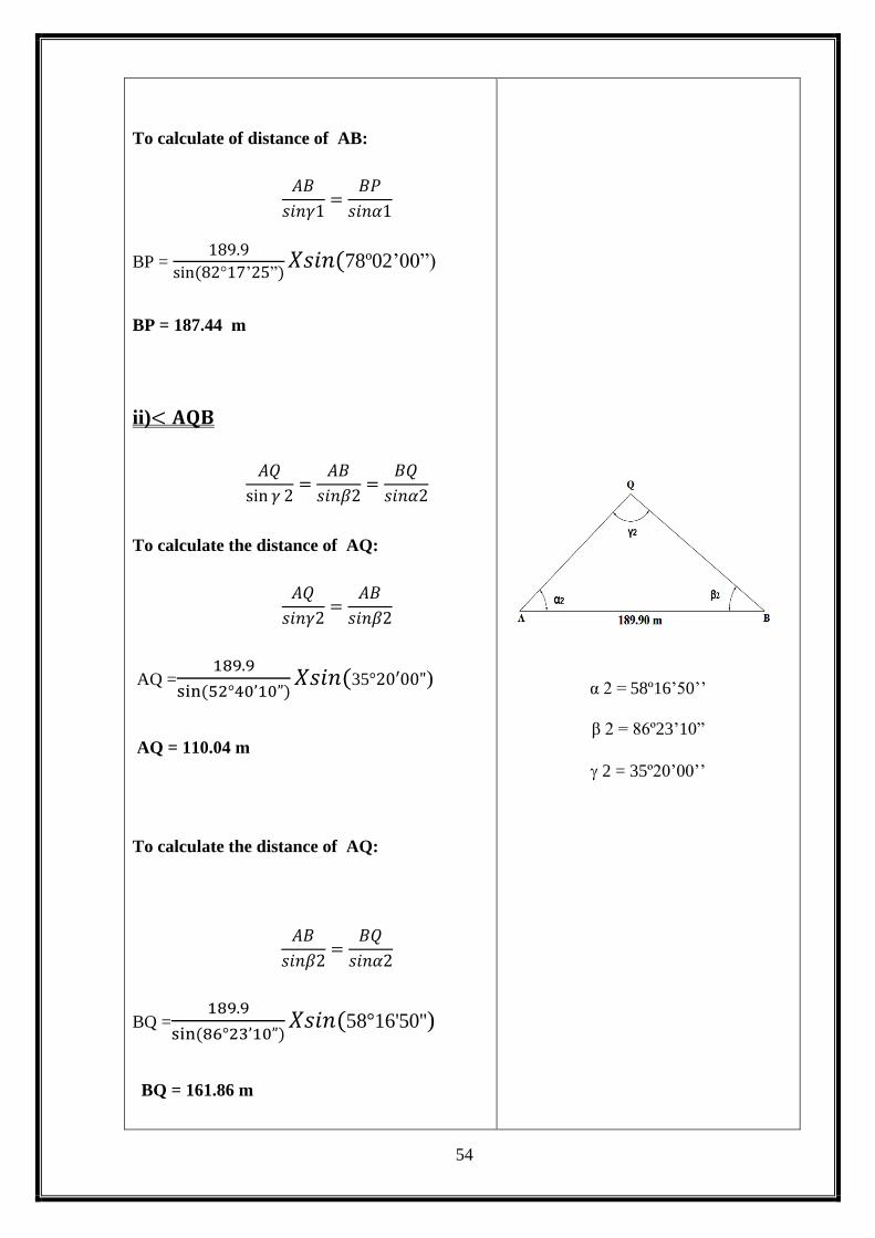
ii)< 𝐀𝐐𝐁
𝐴𝑄
sin 𝛾 2=
𝐴𝐵
𝑠𝑖𝑛𝛽2=
𝐵𝑄
𝑠𝑖𝑛𝛼2
To calculate the distance of AQ:
𝐴𝑄
𝑠𝑖𝑛𝛾2=
𝐴𝐵
𝑠𝑖𝑛𝛽2
AQ =189.9
sin (52°40’10”)𝑋𝑠𝑖𝑛(35°20′00")
AQ = 110.04 m
To calculate the distance of AQ:
𝐴𝐵
𝑠𝑖𝑛𝛽2=
𝐵𝑄
𝑠𝑖𝑛𝛼2
BQ =189.9
sin (86°23’10”)𝑋𝑠𝑖𝑛(58°16'50'')
BQ = 161.86 m
α 2 = 58º16’50’’
β 2 = 86º23’10”
2 = 35º20’00’’

55
iii)< 𝐀𝐑𝐁
𝐴𝐵
sin 𝛾 3=
𝐴𝑅
𝑠𝑖𝑛𝛽3=
𝐵𝑅
𝑠𝑖𝑛𝛼3
To calculate the distance of AR:
𝐴𝐵
𝑠𝑖𝑛𝛾3=
𝐴𝑅
𝑠𝑖𝑛𝛽3
𝐴𝑅 =189.9
sin (102°21′10”)𝑋 sin(37°21′00”)
AR = 117.96 m
To calculate the distance of BR:
𝐴𝐵
𝑠𝑖𝑛𝛾3=
𝐵𝑅
𝑠𝑖𝑛𝛼3
𝐵𝑅 =189.90
sin (102°24′10”)𝑋 sin(40°14’50”)
BR= 125.62 m
iv)< 𝐀𝐒𝐁
𝐴𝐵
sin 𝛾 4=
𝐴𝑆
𝑠𝑖𝑛𝛽4=
𝐵𝑆
𝑠𝑖𝑛𝛼4
To calculate the distance of AS:
𝐴𝐵
𝑠𝑖𝑛𝛾4=
𝐴𝑆
𝑠𝑖𝑛𝛽4
𝐴𝑆 =189.90
sin (47°49′40”)𝑋 sin(109°00′30”)
AS = 242.25 m
α 3 = 40°14’50”
β 3 = 37°21′00”
3 = 102°24′10”
α 4 = 23°09′50”
β 4 = 109°00′30”
4 = 47°49′40”

56
To calculate the distance of BS:
𝐴𝐵
𝑠𝑖𝑛𝛾4=
𝐵𝑆
𝑠𝑖𝑛𝛼4
𝐵𝑆 =189.90
sin (47°49′40”)𝑋 sin(23°09′50”)
BS = 100.79 m
v)< 𝐀𝐓𝐁
𝐴𝐵
sin 𝛾 5=
𝐴𝑇
𝑠𝑖𝑛𝛽5=
𝐵𝑇
𝑠𝑖𝑛𝛼5
To calculate the distance of AT:
𝐴𝐵
𝑠𝑖𝑛𝛾5=
𝐴𝑇
𝑠𝑖𝑛𝛽5
𝐴𝑇 =189.90
sin (139°09′30”)𝑋 sin(125°20′30”)
AT =236.86 m
To calculate the distance of BT:
𝐴𝐵
sin 𝛾 5=
𝐵𝑇
𝑠𝑖𝑛𝛼5
𝐵𝑇 =189.90
sin (139°09′30”)𝑋sin(13°48′30”)
BT = 69.30 m
vi)< 𝐀𝐔𝐁
𝐴𝐵
sin 𝛾 6=
𝐴𝑈
𝑠𝑖𝑛𝛽6=
𝐵𝑈
𝑠𝑖𝑛𝛼6
α 5 = 13°48′30”
β 5 = 125°20′30”
5 = 139°09′30”

57
To calculate the distance of BU:
𝐴𝐵
sin 𝛾 6=
𝐵𝑈
𝑠𝑖𝑛𝛼6
𝐵𝑈 =189.90
sin (04°14′55”)𝑋 sin(3°51′55”)
BU = 175.87 m
To check the distance of AU:
𝐴𝐵
sin 𝛾 6=
𝐴𝑈
𝑠𝑖𝑛𝛽6
𝐴𝑈 =189.90
sin(04°16′55”)𝑋sin(171°45′10”)
AU = 364.83 m
3.9.4 AREA CALCULATION:
Formulas:
Area, A =√𝑠(𝑠 − 𝑎)(𝑠 − 𝑏)(𝑠 − 𝑐)
Where, S =a+b+c
2
𝐢) < 𝐀𝐏𝐁
S =𝑎+𝑏+𝑐
2
= 64.52+189.9+187.47
2
S= 220.945 m
A =√𝑠(𝑠 − 𝑎)(𝑠 − 𝑏)(𝑠 − 𝑐)
A =√220.495(155.975𝑋30.595𝑋33.025)
Area of APB = 5894.86 m2
α 6 = 171°45′10”
β 6 = 03°51′55”
6 = 04°16′55”
a = AP = 64.52 m
b = AB = 189.90 m
c = BP = 187.47 m
58
Area of APB = 1.456 Acre
Area of APB = 0.589 Hectare
𝐢𝐢) < 𝐀𝐐𝐁
S =a+b+c
2
= 110.04+189.9+161.86
2
S = 230.9 m
A =√𝑠(𝑠 − 𝑎)(𝑠 − 𝑏)(𝑠 − 𝑐)
A =√230.9(120.86𝑋41𝑋69.04)
Area of AQB = 8887.83 m2
Area of AQB = 2.196 Acre
Area of AQB = 0.888 Hectare
𝐯𝐢)< 𝐀𝐑𝐁
S =𝑎+𝑏+𝑐
2
= 117.96+189.90+125.62
2
S = 216.74 m
A =√𝑠(𝑠 − 𝑎)(𝑠 − 𝑏)(𝑠 − 𝑐)
A =√216.74(98.78𝑋26.84𝑋91.12)
Area of ARB = 7236.06 m2
Area of ARB = 1.788 Acre
Area of ARB = 0.724 Hectare
a = AQ = 110.04 m
b = AB = 189.90 m
c = BQ = 161.86 m
a = AR = 117.96 m
b = AB = 189.90 m
c = BR = 125.62m
59
𝐢𝐢𝐢) < 𝐀𝐒𝐁
S =𝑎+𝑏+𝑐
2
= 242.25+189.90+100.79
2
S = 266.47 m
A =√𝑠(𝑠 − 𝑎)(𝑠 − 𝑏)(𝑠 − 𝑐)
A =√266.47(24.22𝑋76.57𝑋165.68)
Area of ASB = 9048.48 m2
Area of ASB = 2.235Acre
Area of ASB = 0.905 Hectare
𝐢𝐯) < 𝐀𝐓𝐁
S =𝑎+𝑏+𝑐
2
= 236.86+189.90+69.30
2
S = 248.03 m
A =√𝑠(𝑠 − 𝑎)(𝑠 − 𝑏)(𝑠 − 𝑐)
A =√248.03(11.17𝑋58.13𝑋178.73)
Area of ATB = 5365.09 m2
Area of ATB = 1.326 Acre
Area of ATB = 0.536 Hectare
a = AS = 242.25 m
b = AB = 189.90 m
c = BS = 100.79 m
a = AT = 236.86 m
b = AB = 189.90 m
c = BT = 69.30 m

60
Total Area = APB+AQB+ARB+ASB+ATB+AUB
= 1.456+2.196+1.788+2.235+1.326+0.59
Total Area = 9.591 Acre
i) Area = 9.591 Acre
ii) Area = 38820.75 m2
iii) Area = 3.882 Hectare
3.9.5 TO FIND INTERMEDIATE DISTANCE OF POINTS:
PQ DISTANCE:
∝ = 19º45’10’’
AP = 64.52 m
AQ = 110.04 m
𝐯) < 𝐀𝐔𝐁
S =𝑎+𝑏+𝑐
2
= 364.83+189.90+175.87
2
S = 365.30 m
A =√𝑠(𝑠 − 𝑎)(𝑠 − 𝑏)(𝑠 − 𝑐)
A =√365.30(0.47𝑋175.4𝑋189.43)
Area of SEF = 2388.43 m2
Area of SEF = 0.59Acre
Area of SEF = 0.238 Hectare
a = AU = 364.83 m
b = AB = 189.90 m
c = BU = 175.87 m

61
PQ = √𝐴𝑃2 + 𝐴𝑄2 − 2𝐴𝑝𝑋𝐴𝑄𝑋𝑐𝑜𝑠 ∝
= √64.522 + 110.042 − 2(64.52 𝑋110.04) 𝑥cos (19°45′10")
PQ = 53.92 m
QR DISTANCE:
∝ = 18º02’00’’
AR = 117.96 m
AQ = 110.04 m
QR = √𝐴𝑃2 + 𝐴𝑅2 − 2𝐴𝑄𝑋𝐴𝑅𝑋𝑐𝑜𝑠 ∝
= √110.042 + 117.962 − 2(110.04 𝑋117.96) 𝑥cos (18°02′00")
QR = 36.58 m
RS DISTANCE:
∝ = 17º15’10’’
AR = 117.96 m
AS = 242.25 m
RS = √𝐴𝑅2 + 𝐴𝑆2 − 2𝐴𝑆𝑋𝐴𝑅𝑋𝑐𝑜𝑠 ∝
= √117.962 + 242.252 − 2(117.96 𝑋 242.25) 𝑥cos (17°05′00")
RS = 134.05 m
ST DISTANCE:
∝ = 9°21′20"
AT = 236.86 m
AS = 242.25 m
ST = √𝐴𝑆2 + 𝐴𝑇2 − 2𝐴𝑆𝑋𝐴𝑇𝑋𝑐𝑜𝑠 ∝
= √242.252 + 236.862 − 2(242.25 𝑋 236.86) 𝑥cos (9°21′20")
ST = 39.43 m

62
TU DISTANCE:
∝ = 9°50′35"
AT = 236.86m
AU = 364.83 m
TU = √𝐴𝑆2 + 𝐴𝑇2 − 2𝐴𝑆𝑋𝐴𝑇𝑋𝑐𝑜𝑠 ∝
= √ 236.86 + 364.83 2 − 2(236.25 𝑋364.83 ) 𝑥cos (9°50′35")
TU = 137.55 m
3.9.6 TO FIND OUT VERTICAL DISTANCE OF POINTS:
V =𝐷 tan 𝛼
Where,
D = Horizontal Distance of Point
𝛼 = Vertical Angle of Point
VERTICAL DISTANCE AT P:
V = 𝐷 tan 𝛼
= 64.52 X tan 01º04’20’’
V = 1.21 m
Where,
D = AP Distance = 64.52 m
α = Vertical angle of AP = 01º04’20’’
VERTICAL DISTANCE AT Q:
V = 𝐷 tan 𝛼
= 110.04 X tan 01º20’40’’
V = 2.58 m
Where,
D = AQ Distance = 110.04 m
α = Vertical angle of AP = 01º20’40’’
VERTICAL DISTANCE AT R:
V = 𝐷 tan 𝛼
= 117.96 X tan 00º40’40’’
V = 1.395 m
Where,
D = AR Distance = 117.96 m
α = Vertical angle of AP = 00º40’40’’
VERTICAL DISTANCE AT S:
V = 𝐷 tan 𝛼
= 242.25 X tan 00º40’00’’
V = 2.82 m
Where,
D = AP Distance = 242.25 m
α = Vertical angle of AP = 00º40’00’’

63
VERTICAL DISTANCE AT T:
V = 𝐷 tan 𝛼
= 236.86 X tan 00º36’20’’
V = 2.50 m
Where,
D = AP Distance = 236.86 m
α = Vertical angle of AP = 00º36’20’’
VERTICAL DISTANCE AT U:
V = 𝐷 tan 𝛼
= 364.83 X tan 00º26’30’’
V = 2.81 m
Where,
D = AP Distance = 364.83 m
α = Vertical angle of AP = 00º26’30’’
3.9.7 DETERMINE THE REDUCE LEVEL OF POINTS:
R.L. of bench mark = 100.00
Height of instrument = (10.67 + 1.225) = 11.895m
Reduce level of A = R.L. of BM + H.I
= 100 + 11.895
= 110.67 m
Reduce level of B = R.L. of BM + H.I + V – H2
= 100 + 11.895 + 4.43 + 1.454
= 114.785 m
Reduce level of P = R.L. of BM + H.I - V
= 100 + 11.895 + 1.21
= 110.685
Reduce level of Q = R.L. of BM + H.I - V
= 100 + 11.895 – 2.58
= 109.315 m
Reduce level of R= R.L. of BM + H.I - V
= 100 + 11.895 -1.395
= 110.50 m

64
Reduce level of S = R.L. of BM + H.I - V
= 100 + 11.895 – 2.82
= 109.075 m
Reduce level of T = R.L. of BM + H.I - V
= 100 + 11.895 – 2.50
= 109.395 m
Reduce level of U = R.L. of BM + H.I - V
= 100 + 11.895 – 2.81
= 109.085 m
3.9.8 DETERMINE THE LONGITUDE OF POINTS:
LONGITUTE AT POINT P:
Quadrant - IV
Origin - A = 0°0'00''
At point P = N 1W
Reduced Bering = N 19°45'10'' W
L = Distance of AP = 64.52 m
Longitude : (+ , - )
= L sin1
= 64.52 X sin (19°45'10'')
= -21.80 m
A
A

65
LONGITUDE AT POINT Q:
Quadrant - IV
Origin - A = 0°0'00''
At point Q = N 2 W
Reduced Bering = N 37°47'10'' W
L = Distance of AQ = 110.04 m
Longitude : (+ , - )
= L sin2
= 110.04 X sin (37°47'10'')
= -67.42 m
LONGITUDE AT POINT R:
Quadrant - IV
Origin - A = 0°0'00''
At point Q = N 3 W
Reduced Bering = N 54°52'10'' W
L = Distance of AR = 117.96 m
Q
2
A
A
R
3
A

66
Longitude : (+ , - )
= L sin3
= 117.96 X sin (54°52'10'')
= - 96.47 m
LONGITUDE AT POINT S:
Quadrant - IV
Origin - A = 0°0'00''
At point Q = N 4 W
Reduced Bering = N 64°13'30'' W
L = Distance of AS = 242.25 m
Longitude : (+ , - )
= L sin4
= 242.25 X sin (64°13'30'')
= - 218.15 m
A
S
4
A
A
67
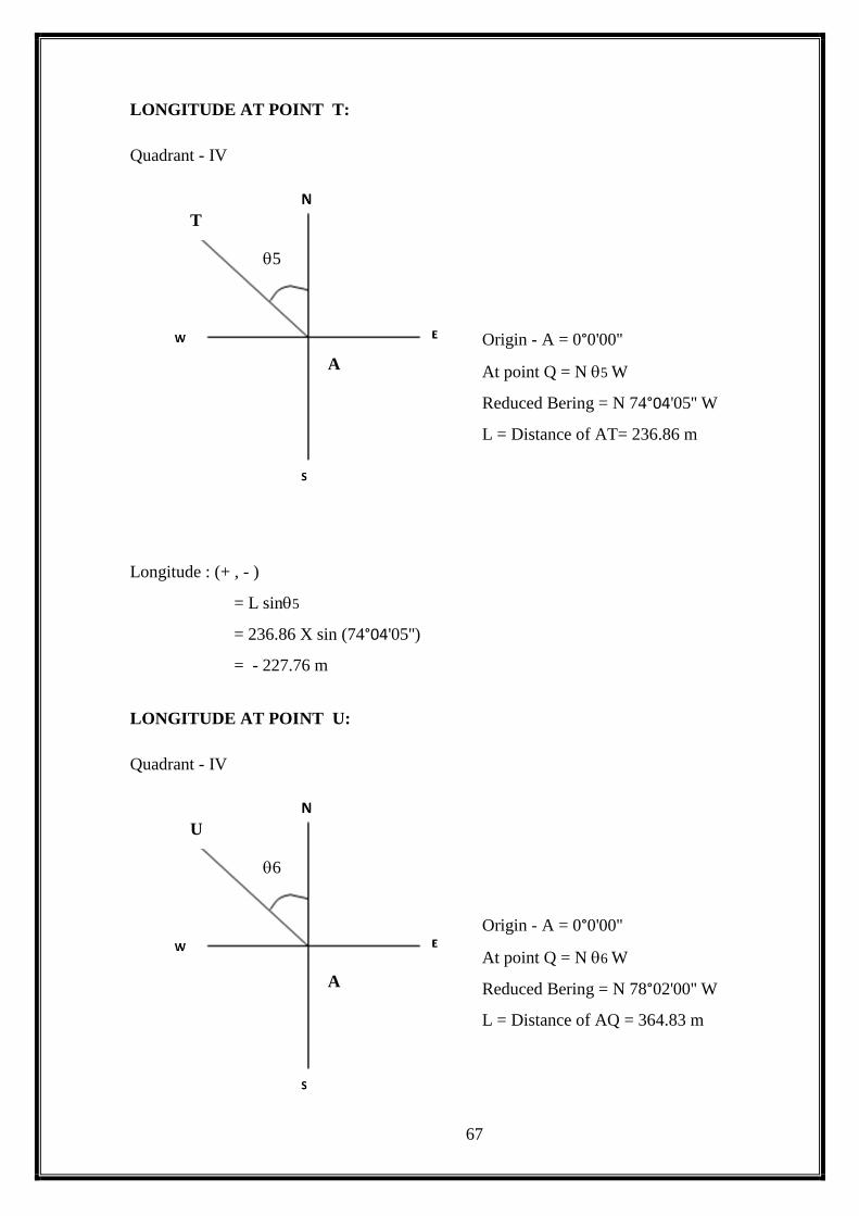
LONGITUDE AT POINT T:
Quadrant - IV
Origin - A = 0°0'00''
At point Q = N 5 W
Reduced Bering = N 74°04'05'' W
L = Distance of AT= 236.86 m
Longitude : (+ , - )
= L sin5
= 236.86 X sin (74°04'05'')
= - 227.76 m
LONGITUDE AT POINT U:
Quadrant - IV
Origin - A = 0°0'00''
At point Q = N 6 W
Reduced Bering = N 78°02'00'' W
L = Distance of AQ = 364.83 m
T
5
A
A
U
6
A
68
Longitude : (+ , - )
= L sin6
= 364.83 X sin (78°02'00'')
= - 356.90 m
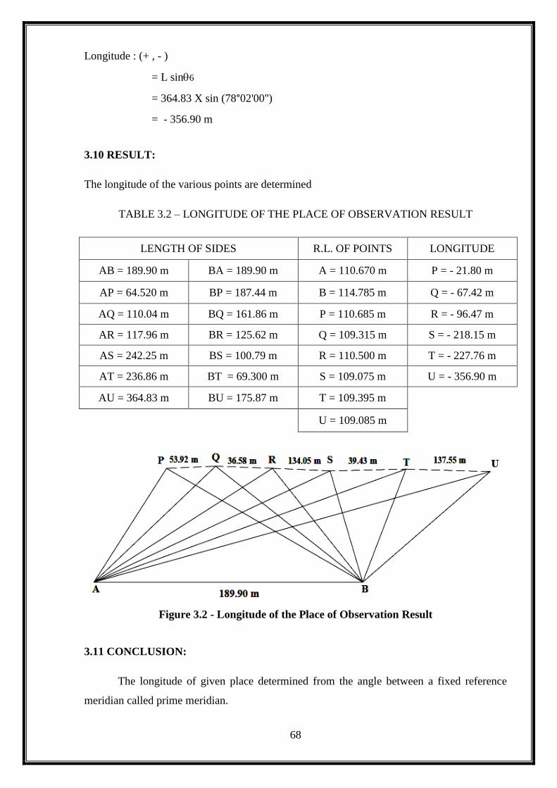
3.10 RESULT:
The longitude of the various points are determined
TABLE 3.2 – LONGITUDE OF THE PLACE OF OBSERVATION RESULT
LENGTH OF SIDES R.L. OF POINTS LONGITUDE
AB = 189.90 m BA = 189.90 m A = 110.670 m P = - 21.80 m
AP = 64.520 m BP = 187.44 m B = 114.785 m Q = - 67.42 m
AQ = 110.04 m BQ = 161.86 m P = 110.685 m R = - 96.47 m
AR = 117.96 m BR = 125.62 m Q = 109.315 m S = - 218.15 m
AS = 242.25 m BS = 100.79 m R = 110.500 m T = - 227.76 m
AT = 236.86 m BT = 69.300 m S = 109.075 m U = - 356.90 m
AU = 364.83 m BU = 175.87 m T = 109.395 m
U = 109.085 m
Figure 3.2 - Longitude of the Place of Observation Result
3.11 CONCLUSION:
The longitude of given place determined from the angle between a fixed reference
meridian called prime meridian.
A
69
4. BLOCK CONTOURING

70
EX.NO:
DATE:
4. BLOCK CONTOURING
4.1 INTRODUCTION:
Contouring is a method of representing the ground surface from using contour
lines. The block contour is a method by which a given area is divided into a number of blocks
of equal dimensions. The map of the area is drawn using this contour line. The contour lines
are imaginary lines on the ground joining the points of equal elevation. These are drawn by
determining the reduced level of various points within the area. The intermediate points may
be chosen based on the convenience.
4.2 INSTRUMENTS USED:
1. Dumpy level:
The dumpy level is used for determining the differences of the
elevations of various stations.
2. Levelling staff:
Leveling staff of 0.005m least count is used to deduce the R.L.of
the points.
3. Metric chain:
A 30 m metric chain is used for setting out the blocks.
4. Arrows & pegs
4.3 RECONNAISSANCE:
The site selected for contouring was an undulated area outside the S.G.I.T
campus. The area was visited by our team one day before we started the exercise. We found
that the area was most suitable for contouring.
4.4 PROCEDURE:
The site of block contour was selected outside our college campus by
reconnaissance survey.
The dimensions were taken to be size of 12000sqm
Then the area was divided into blocks of size 5m x 5m by using cross
staff , chain and ranging rods.
The dumpy levels are fixed at a station such that all the intersecting
points of the blocks were visible.

71
Then the staff readings were taken by keeping the staff at all the
intersecting points of the blocks.
Then the R.L.is determined by the height of collimation method.
Finally, all the reduced levels are plotted in the A2 size graph sheet.
The contours are drawn by connecting the points having the same
reduced levels.
72
4.5 OBSERVATION & TABULATION:
TABLE - 4 BLOCK CONTOURING:
INSTRUMEN
T STATION
SIGHT
TO
B.S
(m)
I. S
(m)
F.S
(m)
HEIGHT OF
INSTRUMEN
T
(m)
REDUCE
D
LEVEL
(m)
REMARK
S
O A1 1.600
101.600 100.000 B.M
A2
1.860
99.740
A3
2.055
99.545
A4
2.310
99.290
A5
2.470
99.130
A6
2.635
98.965
A7
2.790
98.810
O B1
1.890
99.710
B2
2.045
99.555
B3
2.250
99.350
B4
2.420
99.180
B5
2.680
98.920
B6
2.860
98.740
B7
2.955
98.645
O C1
2.045
99.555
C2
2.165
99.435
C3
2.390
99.210
C4
2.600
99.000
C5
2.845
98.755
C6
3.020
98.580
C7
3.030
98.570
O D1
2.200
99.400
D2
2.380
99.220
D3
2.465
99.135
D4
2.765
98.835
D5
2.930
98.670
D6
3.045
98.555
D7
3.150
98.450
O E1
2.320
99.280
E2
2.420
99.180
E3
2.835
98.765
E4
2.945
98.655
E5
3.090
98.510
E6
3.245
98.355
E7
3.235
98.365
73
INSTRUMENT
STATION
SIGHT
TO
B.S
(m)
I. S
(m)
F.S
(m)
HEIGHT OF
INSTRUMENT
(m)
REDUCED
LEVEL
(m)
REMARKS
O F1
2.585
99.015
F2
2.810
98.790
F3
2.950
98.650
F4
3.090
98.510
F5
3.290
98.310
F6
3.365
98.235
F7
3.300
98.300
O G1
2.575
99.025
G2
2.660
98.940
G3
2.720
98.880
G4
2.925
98.675
G5
2.990
98.610
G6
3.150
98.450
G7
3.305
98.295
O H1
1.735
99.865
H2
1.875
99.725
H3
2.160
99.440
H4
2.210
99.390
H5
2.655
98.945
H6
2.830
98.770
H7
3.410
98.190
O I1
1.700
99.900
I2
2.895
98.705
I3
3.110
98.490
I4
3.235
98.365
I5
3.380
98.220
I6
3.400
98.200
I7
3.430 98.170
Check:
∑B.S - ∑F.S = LAST R.L - FIRST R.L
1.600-3.430 = 98.170 - 100.000
-1.830 = -1.830
Note:
Where, B.S - BACK SIGHT
I.S - INTERMEDIATE SIGHT
F.S - FORE SIGHT
Reduced Level Of Given Bench Mark = 100.000 m.
Reduced Level = ( R.L Of Bench Mark + B.S ) - I.S/F.S

74
4.6 RESULT:
The R.L of the various intermediate points was deduced from the staff
readings taken at the site. From the deduced R.L. a contour map was drawn indicating the
points of equal elevation in the given area.
4.7 CONCLUSION:
We gained experience in drawing the contour maps, which can be used for
tracing contour gradients and locating routs, measurements of drainage area and calculating
the reservoir capacity.
75
5. HIGHWAY PROJECT

76
EX.NO:
DATE:
5. HIGHWAY PROJECT
5.1 INTRODUTION:
The highway projects consist of aligning a highway and calculating the earthwork
involved by determining the cross-section of the highway at various intervals. The centerline
was divided into equal intervals. The cross-section of the highway at these regular were found
by cross levelling. The drawing of the cross-section is prepared with formation width and side
slopes. The earthwork involved is calculated from the area of the cross-section.
5.2 INSTRUMENTS USED:
Dumpy level
Levelling staff
Arrows
Chain
Cross staff
Ranging rod
5.3 RECONNAISSANCE:
It is a primary survey that has to be conducted before every survey work.
During this site is visited to get a general idea about how to begin the work.
5.4 PROCEDURE:
Centreline was marked along the alignment of the road.
Assumed road width at ground level was 4m.
Along the centreline the points are marked at 10m interval up to entire length
and named as A, B, C, D, E and F…..
In the traverse direction offsets were marked at 2m interval from each point on both side of
the central line up to edge of the road
1. The staff was kept at all offsets and readings were tabulated.
2. The reduced level of all the offsets is calculated.
3. The cross-section and longitudinal section are drawn in the graph and earth work was
calculated using prismodial formula.

77
5.5 OBSERVATION AND TABULATION:
TABLE 5.1 - CROSS-SECTION:
STATION SIGHT TO B.S
(m)
I.S
(m)
F.S
(m)
H.I
(m)
R.L
(m) REMARKS
A BM
1.470
101.470 100.000
0m
L
1.500
99.970
C
1.470
100.000
R
1.560
99.910
10m
L
1.535
99.935 SPEED
BREAKER C
1.430
100.040
R
1.595
99.875
20m
L
1.580
99.890
C
1.530
99.940
R
1.580
99.890
30m
L
1.600
99.870
C
1.530
99.940
R
1.575
99.895
40m
L
1.645
99.825
C
1.540
99.930
R
1.560
99.910
50m
L
1.630
99.840
C
1.560
99.910
R
1.560
99.910
60m
L
1.600
99.870
C
1.560
99.910
R
1.580
99.890
70m
L
1.640
99.830
C
1.690
99.780
R
1.600
99.870
80m
L
1.610
99.860
C
1.510
99.960
R
1.520
99.950
90m
L
1.580
99.890
C
1.510
99.960
R
1.560
99.910
100m
L
1.650
99.820
C
1.590
99.880
R
1.640
99.830
110m
L
1.940
99.530
C
1.990
99.480
R
1.980
99.490
78
STATION SIGHT TO B.S
(m)
I.S
(m)
F.S
(m)
H.I
(m)
R.L
(m) REMARKS
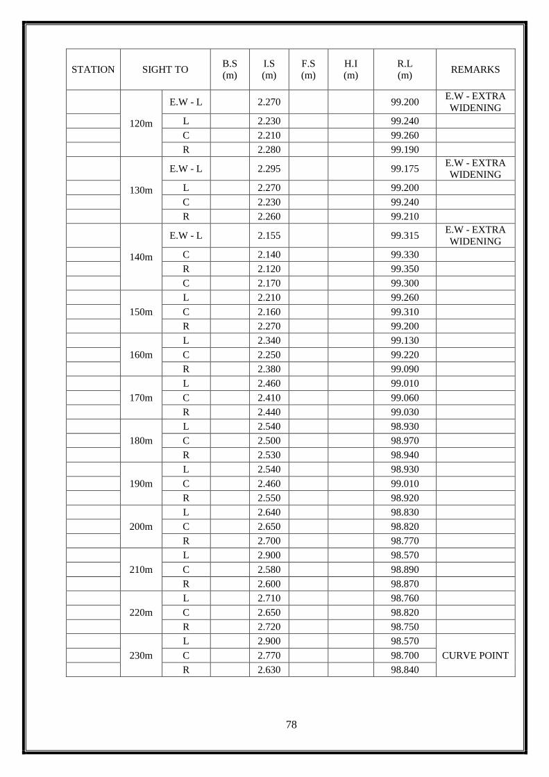
120m
E.W - L
2.270
99.200 E.W - EXTRA
WIDENING
L
2.230
99.240
C
2.210
99.260
R
2.280
99.190
130m
E.W - L
2.295
99.175 E.W - EXTRA
WIDENING
L
2.270
99.200
C
2.230
99.240
R
2.260
99.210
140m
E.W - L
2.155
99.315 E.W - EXTRA
WIDENING
C
2.140
99.330
R
2.120
99.350
C
2.170
99.300
150m
L
2.210
99.260
C
2.160
99.310
R
2.270
99.200
160m
L
2.340
99.130
C
2.250
99.220
R
2.380
99.090
170m
L
2.460
99.010
C
2.410
99.060
R
2.440
99.030
180m
L
2.540
98.930
C
2.500
98.970
R
2.530
98.940
190m
L
2.540
98.930
C
2.460
99.010
R
2.550
98.920
200m
L
2.640
98.830
C
2.650
98.820
R
2.700
98.770
210m
L
2.900
98.570
C
2.580
98.890
R
2.600
98.870
220m
L
2.710
98.760
C
2.650
98.820
R
2.720
98.750
230m
L
2.900
98.570
CURVE POINT
C
2.770
98.700
R
2.630
98.840
79
STATION SIGHT TO B.S
(m)
I.S
(m)
F.S
(m)
H.I
(m)
R.L
(m) REMARKS
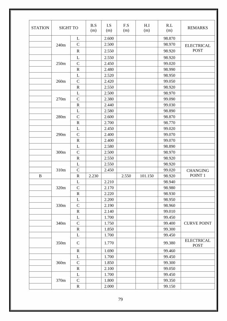
240m
L
2.600
98.870
C
2.500
98.970 ELECTRICAL
POST
R
2.550
98.920
250m
L
2.550
98.920
C
2.450
99.020
R
2.480
98.990
260m
L
2.520
98.950
C
2.420
99.050
R
2.550
98.920
270m
L
2.500
98.970
C
2.380
99.090
R
2.440
99.030
280m
L
2.580
98.890
C
2.600
98.870
R
2.700
98.770
290m
L
2.450
99.020
C
2.400
99.070
R
2.400
99.070
300m
L
2.580
98.890
C
2.500
98.970
R
2.550
98.920
310m
L
2.550
98.920
C
2.450
99.020 CHANGING
POINT 1 B R 2.230
2.550 101.150 98.920
320m
L
2.210
98.940
C
2.170
98.980
R
2.220
98.930
330m
L
2.200
98.950
C
2.190
98.960
R
2.140
99.010
340m
L
1.700
99.450
CURVE POINT
C
1.750
99.400
R
1.850
99.300
350m
L
1.700
99.450
C
1.770
99.380
ELECTRICAL
POST
R
1.690
99.460
360m
L
1.700
99.450
C
1.850
99.300
R
2.100
99.050
370m
L
1.700
99.450
C
1.800
99.350
R
2.000
99.150

80
STATION SIGHT TO B.S
(m)
I.S
(m)
F.S
(m)
H.I
(m)
R.L
(m) REMARKS
380m
L
1.800
99.350
C
1.750
99.400
R
1.820
99.330
390m
L
1.950
99.200
C
1.980
99.170
R
2.000
99.150
400m
L
2.220
98.930
C
2.140
99.010
R
2.100
99.050
410m
L
2.140
99.010
CURVE POINT
C
1.950
99.200
R
1.690
99.460
420m
L
1.950
99.200
CURVE POINT
C
1.870
99.280
R
1.800
99.350
430m
L
1.800
99.350 ELECTRICAL
POST
C
1.770
99.380
R
1.750
99.400
440m
L
1.630
99.520 ELECTRICAL
POST
C
1.580
99.570
R
1.630
99.520
450m
L
1.590
99.560
C
1.590
99.560
R
1.580
99.570
460m
L
1.400
99.750
C
1.400
99.750
R
1.510
99.640
470m
L
1.350
99.800
C
1.360
99.790
R
1.470
99.680
480m
L
1.360
99.790
C
1.360
99.790
R
1.470
99.680
490m
L
1.390
99.760
C
1.390
99.760
R
1.470
99.680
500m
L
1.360
99.790
C
1.390
99.760
R
1.470
99.680
510m
L
1.440
99.710
C
1.360
99.790
R
1.360
99.790

81
STATION SIGHT TO B.S
(m)
I.S
(m)
F.S
(m)
H.I
(m)
R.L
(m) REMARKS
520m
L
1.450
99.700
C
1.350
99.800
R
1.360
99.790
530m
L
1.440
99.710
C
1.360
99.790
R
1.370
99.780
540m
L
1.400
99.750
C
1.320
99.830
R
1.390
99.760
550m
L
1.360
99.790
CONSTRUCTIO
N ARCH
C
1.300
99.850
R
1.390
99.760
560m
L
1.390
99.760 ELECTRICAL
POST
C
1.300
99.850
R
1.400
99.750
570m
L
1.370
99.780
C
1.300
99.850
R
1.370
99.780
580m
L
1.390
99.760
C
1.370
99.780
R
1.390
99.760
590m
L
1.370
99.780
C
1.350
99.800
R
1.410
99.740
600m
L
1.340
99.810
C
1.360
99.790
R
1.420
99.730
610m
L
1.390
99.760
C
1.340
99.810
R
1.400
99.750
620m
L
1.420
99.730
C
1.340
99.810
R
1.510
99.640
630m
L
1.400
99.750
C
1.400
99.750
R
1.480
99.670
640m
L
1.420
99.730
C
1.400
99.750 CHANGING
POINT 2 C R 2.030
1.420 101.760 99.730
650m
L
1.990
99.770
C
1.950
99.810 ELECTRICAL
POST
R
2.025
99.735
82
STATION SIGHT TO B.S
(m)
I.S
(m)
F.S
(m)
H.I
(m)
R.L
(m) REMARKS
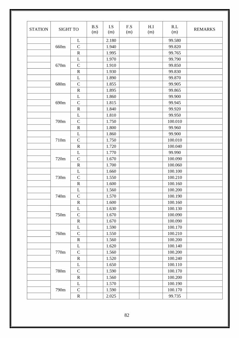
660m
L
2.180
99.580
C
1.940
99.820
R
1.995
99.765
670m
L
1.970
99.790
C
1.910
99.850
R
1.930
99.830
680m
L
1.890
99.870
C
1.855
99.905
R
1.895
99.865
690m
L
1.860
99.900
C
1.815
99.945
R
1.840
99.920
700m
L
1.810
99.950
C
1.750
100.010
R
1.800
99.960
710m
L
1.860
99.900
C
1.750
100.010
R
1.720
100.040
720m
L
1.770
99.990
C
1.670
100.090
R
1.700
100.060
730m
L
1.660
100.100
C
1.550
100.210
R
1.600
100.160
740m
L
1.560
100.200
C
1.570
100.190
R
1.600
100.160
750m
L
1.630
100.130
C
1.670
100.090
R
1.670
100.090
760m
L
1.590
100.170
C
1.550
100.210
R
1.560
100.200
770m
L
1.620
100.140
C
1.560
100.200
R
1.520
100.240
780m
L
1.650
100.110
C
1.590
100.170
R
1.560
100.200
790m
L
1.570
100.190
C
1.590
100.170
R
2.025
99.735
83
STATION SIGHT TO B.S
(m)
I.S
(m)
F.S
(m)
H.I
(m)
R.L
(m) REMARKS
800m
L
1.690
100.070
C
1.570
100.190
R
1.600
100.160
810m
L
1.690
100.070
C
1.590
100.170
R
1.670
100.090
820m
L
1.690
100.070
C
1.630
100.130
R
1.640
100.120
830m
L
1.650
100.110
C
1.630
100.130
R
1.690
100.070
840m
L
1.650
100.110
C
1.700
100.060
R
1.820
99.940
850m
L
1.340
100.420
CURVE POINT
C
1.730
100.030
R
1.710
100.050
860m
L
1.860
99.900
C
1.770
99.990
R
1.750
100.010
870m
L
2.100
99.660
C
1.890
99.870
R
1.740
100.020
880m
L
2.100
99.660
CURVE POINT
C
1.900
99.860
R
1.700
100.060
890m
L
1.900
99.860
C
1.800
99.960
R
1.800
99.960
900m
L
1.900
99.860
C
1.810
99.950
R
1.830
99.930
910m
L
2.100
99.660
C
1.900
99.860
D R 1.650
1.900 101.510 99.860 CHANGING
POINT 3
920m
L
1.300
100.210
C
1.600
99.910
R
1.700
99.810
930m
L
1.330
100.180
C
1.630
99.880
CONSTRUCTIO
N ARCH
R
1.730
99.780
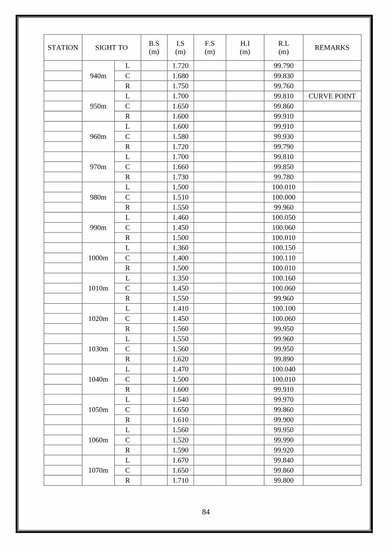
84
STATION SIGHT TO B.S
(m)
I.S
(m)
F.S
(m)
H.I
(m)
R.L
(m) REMARKS
940m
L
1.720
99.790
C
1.680
99.830
R
1.750
99.760
950m
L
1.700
99.810 CURVE POINT
C
1.650
99.860
R
1.600
99.910
960m
L
1.600
99.910
C
1.580
99.930
R
1.720
99.790
970m
L
1.700
99.810
C
1.660
99.850
R
1.730
99.780
980m
L
1.500
100.010
C
1.510
100.000
R
1.550
99.960
990m
L
1.460
100.050
C
1.450
100.060
R
1.500
100.010
1000m
L
1.360
100.150
C
1.400
100.110
R
1.500
100.010
1010m
L
1.350
100.160
C
1.450
100.060
R
1.550
99.960
1020m
L
1.410
100.100
C
1.450
100.060
R
1.560
99.950
1030m
L
1.550
99.960
C
1.560
99.950
R
1.620
99.890
1040m
L
1.470
100.040
C
1.500
100.010
R
1.600
99.910
1050m
L
1.540
99.970
C
1.650
99.860
R
1.610
99.900
1060m
L
1.560
99.950
C
1.520
99.990
R
1.590
99.920
1070m
L
1.670
99.840
C
1.650
99.860
R
1.710
99.800
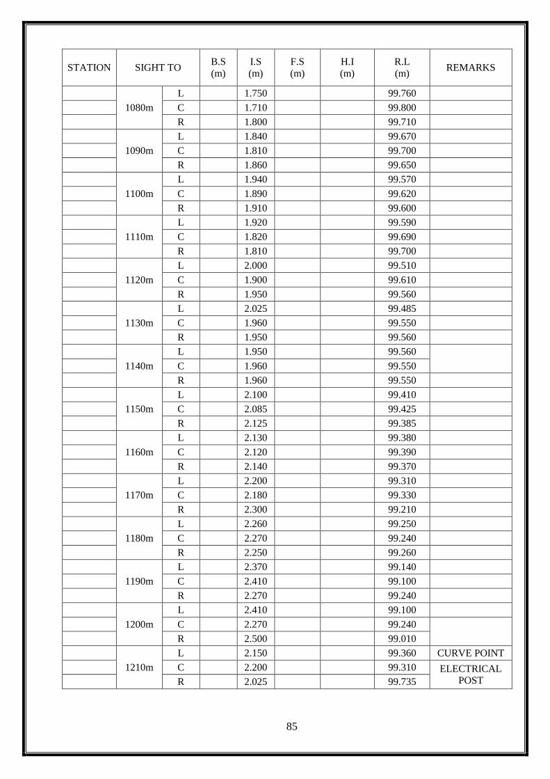
85
STATION SIGHT TO B.S
(m)
I.S
(m)
F.S
(m)
H.I
(m)
R.L
(m) REMARKS
1080m
L
1.750
99.760
C
1.710
99.800
R
1.800
99.710
1090m
L
1.840
99.670
C
1.810
99.700
R
1.860
99.650
1100m
L
1.940
99.570
C
1.890
99.620
R
1.910
99.600
1110m
L
1.920
99.590
C
1.820
99.690
R
1.810
99.700
1120m
L
2.000
99.510
C
1.900
99.610
R
1.950
99.560
1130m
L
2.025
99.485
C
1.960
99.550
R
1.950
99.560
1140m
L
1.950
99.560
C
1.960
99.550
R
1.960
99.550
1150m
L
2.100
99.410
C
2.085
99.425
R
2.125
99.385
1160m
L
2.130
99.380
C
2.120
99.390
R
2.140
99.370
1170m
L
2.200
99.310
C
2.180
99.330
R
2.300
99.210
1180m
L
2.260
99.250
C
2.270
99.240
R
2.250
99.260
1190m
L
2.370
99.140
C
2.410
99.100
R
2.270
99.240
1200m
L
2.410
99.100
C
2.270
99.240
R
2.500
99.010
1210m
L
2.150
99.360 CURVE POINT
C
2.200
99.310 ELECTRICAL
POST
R
2.025
99.735
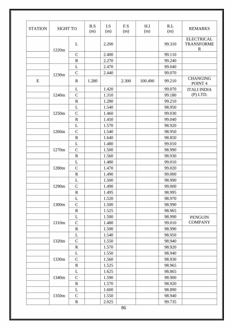
86
STATION SIGHT TO B.S
(m)
I.S
(m)
F.S
(m)
H.I
(m)
R.L
(m) REMARKS
1220m
L
2.200
99.310
ELECTRICAL
TRANSFORME
R
C
2.400
99.110
R
2.270
99.240
1230m
L
2.470
99.040
C
2.440
99.070
E R 1.280
2.300 100.490 99.210 CHANGING
POINT 4
1240m
L
1.420
99.070 ITALI INDIA
(P) LTD.
C
1.310
99.180
R
1.280
99.210
1250m
L
1.540
98.950
C
1.460
99.030
R
1.450
99.040
1260m
L
1.570
98.920
C
1.540
98.950
R
1.640
98.850
1270m
L
1.480
99.010
C
1.500
98.990
R
1.560
98.930
1280m
L
1.480
99.010
C
1.470
99.020
R
1.490
99.000
1290m
L
1.500
98.990
C
1.490
99.000
R
1.495
98.995
1300m
L
1.520
98.970
C
1.500
98.990
R
1.525
98.965
1310m
L
1.500
98.990 PENGUIN
COMPANY
C
1.480
99.010
R
1.500
98.990
1320m
L
1.540
98.950
C
1.550
98.940
R
1.570
98.920
1330m
L
1.550
98.940
C
1.560
98.930
R
1.525
98.965
1340m
L
1.625
98.865
C
1.590
98.900
R
1.570
98.920
1350m
L
1.600
98.890
C
1.550
98.940
R
2.025
99.735

87
STATION SIGHT TO B.S
(m)
I.S
(m)
F.S
(m)
H.I
(m)
R.L
(m) REMARKS
1360m
L 1.570 98.920
C 1.540 98.950
R 1.550 98.940
1370m
L 1.570 98.920
C 1.520 98.970
R 1.575 98.915
1380m
L 1.640 98.850
C 1.580 98.910
R 1.575 98.915
1390m
L 1.660 98.830
C 1.610 98.880
R 1.625 98.865
1400m
L 1.695 98.795
C 1.625 98.865
R 1.640 98.850
1410m
L 1.620 98.870
C 1.630 98.860
R 1.645 98.845
1420m
L 1.490 99.000
C 1.525 98.965
R 1.630 98.860
1430m
L 1.410 99.080 CURVE POINT
C 1.430 99.060
R 1.500 98.990
1440m
L 1.450 99.040
C 1.400 99.090
R 1.450 99.040
1450m
L 1.390 99.100
C 1.325 99.165
R 1.390 99.100
1460m
L 1.295 99.195
C 1.245 99.245
R 1.285 99.205
1470m
L 1.260 99.230
C 1.240 99.250
R 1.290 99.200
1480m
L 1.250 99.240
C 1.210 99.280
R 1.240 99.250
1490m
L 1.215 99.275
C 1.110 99.380
R 2.025 99.735

88
STATION SIGHT TO B.S
(m)
I.S
(m)
F.S
(m)
H.I
(m)
R.L
(m) REMARKS
1500m
L
1.120
99.370
C
1.100
99.390
R
1.150
99.340
1510m
L
1.110
99.380 CURVE POINT
C
1.140
99.350 3 - ROAD CROSS
F R 1.850
1.200 101.140 99.290 CHANGING POINT 5
1520m
L
1.840
99.300
C
1.795
99.345
R
1.790
99.350
1530m
L
1.850
99.290
C
1.810
99.330
R
1.810
99.330
1540m
L
1.730
99.410
C
1.810
99.330
R
1.805
99.335
1550m
L
1.640
99.500 CURVE POINT
C
1.730
99.410
R
1.830
99.310
1560m
L
1.545
99.595 CURVE POINT
C
1.620
99.520
R
1.715
99.425
1570m
L
1.550
99.590
C
1.595
99.545
R
1.650
99.490
1580m
L
1.345
99.795
C
1.405
99.735
R
1.525
99.615
1590m
L
1.390
99.750
C
1.395
99.745
R
1.460
99.680
1600m
L
1.370
99.770
C
1.415
99.725
R
1.480
99.660
1610m
L
1.265
99.875
C
1.325
99.815
R
1.410
99.730
1620m
L
1.200
99.940
C
1.270
99.870 CHANGING
POINT 6 G R 2.430
1.400 102.170 99.740
1630m
L
2.325
99.845
C
2.390
99.780 ELECTRICAL
TOWER
R
2.025
99.735

89
STATION SIGHT TO B.S
(m)
I.S
(m)
F.S
(m)
H.I
(m)
R.L
(m) REMARKS
1640m
L
2.210
99.960
C
2.230
99.940
R
2.295
99.875
1650m
L
2.080
100.090
C
2.100
100.070
R
2.200
99.970
1660m
L
1.900
100.270
C
1.945
100.225
R
2.010
100.160
1670m
L
1.770
100.400
C
1.790
100.380
R
1.865
100.305
1680m
L
1.645
100.525
C
1.650
100.520
R
1.670
100.500
1690m
L
1.550
100.620
C
1.520
100.650
R
1.415
100.755
1700m
L
1.410
100.760
C
1.400
100.770
R
1.410
100.760
1710m
L
1.385
100.785
C
1.400
100.770
R
1.405
100.765
1720m
L
1.490
100.680
C
1.450
100.720
R
1.390
100.780
1730m
L
1.525
100.645
C
1.530
100.640
R
1.575
100.595
1740m
L
1.660
100.510
C
1.950
100.220
R
1.610
100.560
1750m
L
1.680
100.490
C
1.685
100.485
R
1.700
100.470 ELECTRICAL
TOWER &
CHANGING
POINT 7
1760m
L
1.700
100.470
C
1.770
100.400
H R 1.265
1.810 101.625 100.360
1770m
L
1.245
100.380
C
1.230
100.395
R
2.025
99.735

90
STATION SIGHT TO B.S
(m)
I.S
(m)
F.S
(m)
H.I
(m)
R.L
(m) REMARKS
1780m
L
1.320
100.305
C
1.300
100.325
R
1.275
100.350
1790m
L
1.350
100.275
C
1.305
100.320
R
1.345
100.280
1800m
L
1.420
100.205
C
1.370
100.255
R
1.385
100.240
1810m
L
1.495
100.130
C
1.395
100.230
R
1.375
100.250
1820m
L
1.560
100.065
C
1.470
100.155
R
1.460
100.165
1830m
L
1.550
100.075
C
1.475
100.150
R
1.560
100.065
1840m
L
1.565
100.060
C
1.505
100.120
R
1.550
100.075
1850m
L
1.535
100.090
C
1.505
100.120
R
1.565
100.060
1860m
L
1.455
100.170
C
1.405
100.220
R
1.405
100.220
1870m
L
1.400
100.225
C
1.370
100.255
R
1.375
100.250
1880m
L
1.530
100.095
C
1.465
100.160
R
1.485
100.140
1890m
L
1.585
100.040
C
1.530
100.095
R
1.570
100.055
1900m
L
1.545
100.080
C
1.560
100.065 CHANGING
POINT 8 I R 2.365
1.585 102.405 100.040
1910m
L
2.390
100.015
C
2.460
99.945
R
2.520
99.885
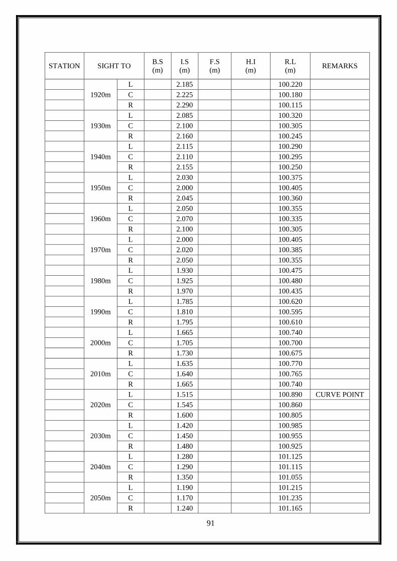
91
STATION SIGHT TO B.S
(m)
I.S
(m)
F.S
(m)
H.I
(m)
R.L
(m) REMARKS
1920m
L
2.185
100.220
C
2.225
100.180
R
2.290
100.115
1930m
L
2.085
100.320
C
2.100
100.305
R
2.160
100.245
1940m
L
2.115
100.290
C
2.110
100.295
R
2.155
100.250
1950m
L
2.030
100.375
C
2.000
100.405
R
2.045
100.360
1960m
L
2.050
100.355
C
2.070
100.335
R
2.100
100.305
1970m
L
2.000
100.405
C
2.020
100.385
R
2.050
100.355
1980m
L
1.930
100.475
C
1.925
100.480
R
1.970
100.435
1990m
L
1.785
100.620
C
1.810
100.595
R
1.795
100.610
2000m
L
1.665
100.740
C
1.705
100.700
R
1.730
100.675
2010m
L
1.635
100.770
C
1.640
100.765
R
1.665
100.740
2020m
L
1.515
100.890 CURVE POINT
C
1.545
100.860
R
1.600
100.805
2030m
L
1.420
100.985
C
1.450
100.955
R
1.480
100.925
2040m
L
1.280
101.125
C
1.290
101.115
R
1.350
101.055
2050m
L
1.190
101.215
C
1.170
101.235
R
1.240
101.165

92
STATION SIGHT TO B.S
(m)
I.S
(m)
F.S
(m)
H.I
(m)
R.L
(m) REMARKS
2060m
L
1.185
101.220
C
1.235
101.170
R
1.265
101.140
2070m
L
1.350
101.055
C
1.335
101.070
R
1.380
101.025
2080m
L
1.350
101.055 CURVE POINT
C
1.425
100.980
R
1.470
100.935
2090m
L
1.445
100.960
C
1.485
100.920
R
1.535
100.870
2100m
L
1.545
100.860
C
1.510
100.895
R
1.520
100.885
2110m
L
1.490
100.915
C
1.600
100.805 CHANGING
POINT 9 J R 1.355
1.600 102.160 100.805
2120m
L
1.340
100.820
C
1.350
100.810
R
1.360
100.800
2130m
L
1.375
100.785
C
1.325
100.835
R
1.315
100.845
2140m
L
1.410
100.750
C
1.355
100.805
R
1.345
100.815
2150m
L
1.460
100.700
C
1.430
100.730
R
1.435
100.725
2160m
L
1.445
100.715
C
1.450
100.710
R
1.500
100.660
2170m
L
1.455
100.705
C
1.430
100.730
R
1.480
100.680
2180m
L
1.500
100.660
C
1.470
100.690
R
1.490
100.670
2190m
L
1.500
100.660
C
1.470
100.690
R
1.500
100.660
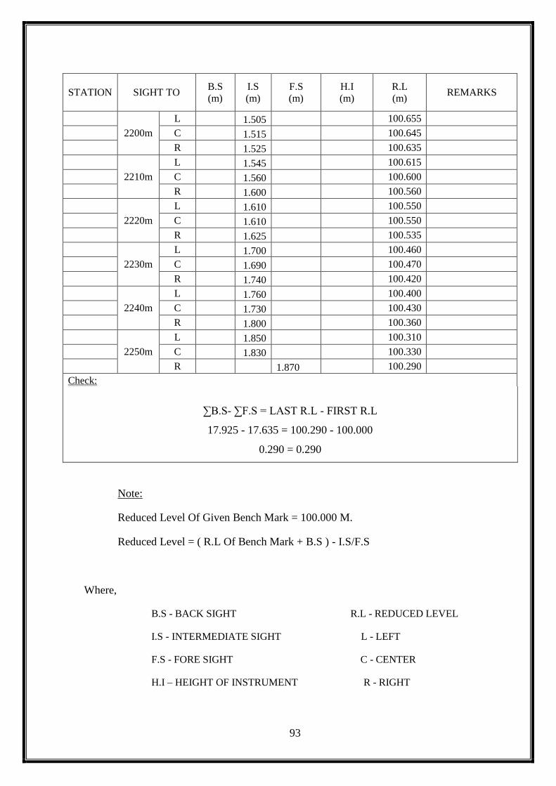
93
STATION SIGHT TO B.S
(m)
I.S
(m)
F.S
(m)
H.I
(m)
R.L
(m) REMARKS
2200m
L 1.505 100.655
C 1.515 100.645
R 1.525 100.635
2210m
L 1.545 100.615
C 1.560 100.600
R 1.600 100.560
2220m
L 1.610 100.550
C 1.610 100.550
R 1.625 100.535
2230m
L 1.700 100.460
C 1.690 100.470
R 1.740 100.420
2240m
L 1.760 100.400
C 1.730 100.430
R 1.800 100.360
2250m
L 1.850 100.310
C 1.830 100.330
R 1.870 100.290
Check:
∑B.S- ∑F.S = LAST R.L - FIRST R.L
17.925 - 17.635 = 100.290 - 100.000
0.290 = 0.290
Note:
Reduced Level Of Given Bench Mark = 100.000 M.
Reduced Level = ( R.L Of Bench Mark + B.S ) - I.S/F.S
Where,
B.S - BACK SIGHT R.L - REDUCED LEVEL
I.S - INTERMEDIATE SIGHT L - LEFT
F.S - FORE SIGHT C - CENTER
H.I – HEIGHT OF INSTRUMENT R - RIGHT

94
TABLE 5.2 - LONGITUDINAL SECTION:
STATION SIGHT TO B.S
(m)
I.S
(m)
F.S
(m)
H.I
(m)
R.L
(m) REMARKS
A BM
1.470
101.470 100.000 BENCH MARK
0m C
1.470
100.000
10m C
1.430
100.040
20m C
1.530
99.940
30m C
1.530
99.940
40m C
1.540
99.930
50m C
1.560
99.910
60m C
1.560
99.910
70m C
1.690
99.780
80m C
1.510
99.960
90m C
1.510
99.960
100m C
1.590
99.880
110m C
1.990
99.480
120m C
2.210
99.260
130m C
2.230
99.240
140m C
2.120
99.350
150m C
2.160
99.310
160m C
2.250
99.220
170m C
2.410
99.060
180m C
2.500
98.970
190m C
2.460
99.010
200m C
2.650
98.820
210m C
2.580
98.890
220m C
2.650
98.820
230m C
2.770
98.700
240m C
2.500
98.970
250m C
2.450
99.020
260m C
2.420
99.050
270m C
2.380
99.090
280m C
2.600
98.870
290m C
2.400
99.070
300m C
2.500
98.970
310m C
2.450
99.020
320m C
2.170
101.150 98.980
CHANGING
POINT 1
330m C
2.190
98.960
340m C
1.750
99.400
350m C
1.770
99.380
360m C
1.850
99.300
370m C
1.800
99.350
380m C
1.750
99.400
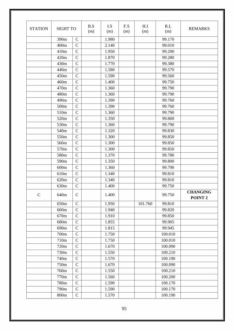
95
STATION SIGHT TO B.S
(m)
I.S
(m)
F.S
(m)
H.I
(m)
R.L
(m) REMARKS
390m C
1.980
99.170
400m C
2.140
99.010
410m C
1.950
99.200
420m C
1.870
99.280
430m C
1.770
99.380
440m C
1.580
99.570
450m C
1.590
99.560
460m C
1.400
99.750
470m C
1.360
99.790
480m C
1.360
99.790
490m C
1.390
99.760
500m C
1.390
99.760
510m C
1.360
99.790
520m C
1.350
99.800
530m C
1.360
99.790
540m C
1.320
99.830
550m C
1.300
99.850
560m C
1.300
99.850
570m C
1.300
99.850
580m C
1.370
99.780
590m C
1.350
99.800
600m C
1.360
99.790
610m C
1.340
99.810
620m C
1.340
99.810
630m C
1.400
99.750
C 640m C
1.400
99.750 CHANGING
POINT 2
650m C
1.950
101.760 99.810
660m C
1.940
99.820
670m C
1.910
99.850
680m C
1.855
99.905
690m C
1.815
99.945
700m C
1.750
100.010
710m C
1.750
100.010
720m C
1.670
100.090
730m C
1.550
100.210
740m C
1.570
100.190
750m C
1.670
100.090
760m C
1.550
100.210
770m C
1.560
100.200
780m C
1.590
100.170
790m C
1.590
100.170
800m C
1.570
100.190

96
STATION SIGHT TO B.S
(m)
I.S
(m)
F.S
(m)
H.I
(m)
R.L
(m) REMARKS
810m C
1.590
100.170
820m C
1.630
100.130
830m C
1.630
100.130
840m C
1.700
100.060
850m C
1.730
100.030
860m C
1.770
99.990
870m C
1.890
99.870
880m C
1.900
99.860
890m C
1.800
99.960
900m C
1.810
99.950
D 910m C
1.900
101.510 99.860 CHANGING
POINT 3
920m C
1.600
99.910
930m C
1.630
99.880
940m C
1.680
99.830
950m C
1.650
99.860
960m C
1.580
99.930
970m C
1.660
99.850
980m C
1.510
100.000
990m C
1.450
100.060
1000m C
1.400
100.110
1010m C
1.450
100.060
1020m C
1.450
100.060
1030m C
1.560
99.950
1040m C
1.500
100.010
1050m C
1.650
99.860
1060m C
1.520
99.990
1070m C
1.650
99.860
1080m C
1.710
99.800
1090m C
1.810
99.700
1100m C
1.890
99.620
1110m C
1.820
99.690
1120m C
1.900
99.610
1130m C
1.960
99.550
1140m C
1.960
99.550
1150m C
2.085
99.425
1160m C
2.120
99.390
1170m C
2.180
99.330
1180m C
2.270
99.240
1190m C
2.410
99.100
1200m C
2.270
99.240
1210m C
2.200
99.310
1220m C
2.400
99.110
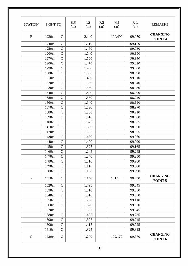
97
STATION SIGHT TO B.S
(m)
I.S
(m)
F.S
(m)
H.I
(m)
R.L
(m) REMARKS
E 1230m C
2.440
100.490 99.070 CHANGING
POINT 4
1240m C
1.310
99.180
1250m C
1.460
99.030
1260m C
1.540
98.950
1270m C
1.500
98.990
1280m C
1.470
99.020
1290m C
1.490
99.000
1300m C
1.500
98.990
1310m C
1.480
99.010
1320m C
1.550
98.940
1330m C
1.560
98.930
1340m C
1.590
98.900
1350m C
1.550
98.940
1360m C
1.540
98.950
1370m C
1.520
98.970
1380m C
1.580
98.910
1390m C
1.610
98.880
1400m C
1.625
98.865
1410m C
1.630
98.860
1420m C
1.525
98.965
1430m C
1.430
99.060
1440m C
1.400
99.090
1450m C
1.325
99.165
1460m C
1.245
99.245
1470m C
1.240
99.250
1480m C
1.210
99.280
1490m C
1.110
99.380
1500m C
1.100
99.390
F 1510m C
1.140
101.140 99.350 CHANGING
POINT 5
1520m C
1.795
99.345
1530m C
1.810
99.330
1540m C
1.810
99.330
1550m C
1.730
99.410
1560m C
1.620
99.520
1570m C
1.595
99.545
1580m C
1.405
99.735
1590m C
1.395
99.745
1600m C
1.415
99.725
1610m C
1.325
99.815
G 1620m C
1.270
102.170 99.870 CHANGING
POINT 6

98
STATION SIGHT TO B.S
(m)
I.S
(m)
F.S
(m)
H.I
(m)
R.L
(m) REMARKS
1630m C
2.390
99.780
1640m C
2.230
99.940
1650m C
2.100
100.070
1660m C
1.945
100.225
1670m C
1.790
100.380
1680m C
1.650
100.520
1690m C
1.520
100.650
1700m C
1.400
100.770
1710m C
1.400
100.770
1720m C
1.450
100.720
1730m C
1.530
100.640
1740m C
1.950
100.220
1750m C
1.685
100.485
H 1760m C
1.770
101.625 100.400 CHANGING
POINT 7
1770m C
1.230
100.395
1780m C
1.300
100.325
1790m C
1.305
100.320
1800m C
1.370
100.255
1810m C
1.395
100.230
1820m C
1.470
100.155
1830m C
1.475
100.150
1840m C
1.505
100.120
1850m C
1.505
100.120
1860m C
1.405
100.220
1870m C
1.370
100.255
1880m C
1.465
100.160
1890m C
1.530
100.095
I 1900m C
1.560
102.405 100.065 CHANGING
POINT 8
1910m C
2.460
99.945
1920m C
2.225
100.180
1930m C
2.100
100.305
1940m C
2.110
100.295
1950m C
2.000
100.405
1960m C
2.070
100.335
1970m C
2.020
100.385
1980m C
1.925
100.480
1990m C
1.810
100.595
2000m C
1.705
100.700
2010m C
1.640
100.765
2020m C
1.545
100.860
2030m C
1.450
100.955

99
STATION SIGHT TO B.S
(m)
I.S
(m)
F.S
(m)
H.I
(m)
R.L
(m) REMARKS
2040m C
1.290
101.115
2050m C
1.170
101.235
2060m C
1.235
101.170
2070m C
1.335
101.070
2080m C
1.425
100.980
2090m C
1.485
100.920
2100m C
1.510
100.895
J 2110m C
1.600
102.160 100.805 CHANGING
POINT 9
2120m C
1.350
100.810
2130m C
1.325
100.835
2140m C
1.355
100.805
2150m C
1.430
100.730
2160m C
1.450
100.710
2170m C
1.430
100.730
2180m C
1.470
100.690
2190m C
1.470
100.690
2200m C
1.515
100.645
2210m C
1.560
100.600
2220m C
1.610
100.550
2230m C
1.690
100.470
2240m C
1.730
100.430
2250m C
1.830
100.330
Note:
Reduced Level Of Given Bench Mark = 100.000 m.
Reduced Level =( R.L Of Bench Mark + B.S ) - I.S/F.S
Where,
B.S - BACK SIGHT R.L - REDUCED LEVEL
I.S - INTERMEDIATE SIGHT L - LEFT
F.S - FORE SIGHT C - CENTER
H.I – HEIGHT OF INSTRUMENT R - RIGHT
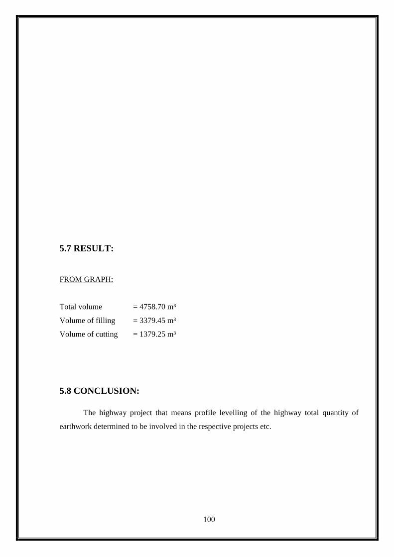
100
5.7 RESULT:
FROM GRAPH:
Total volume = 4758.70 m³
Volume of filling = 3379.45 m³
Volume of cutting = 1379.25 m³
5.8 CONCLUSION:
The highway project that means profile levelling of the highway total quantity of
earthwork determined to be involved in the respective projects etc.
101
6. TRIANGULATION
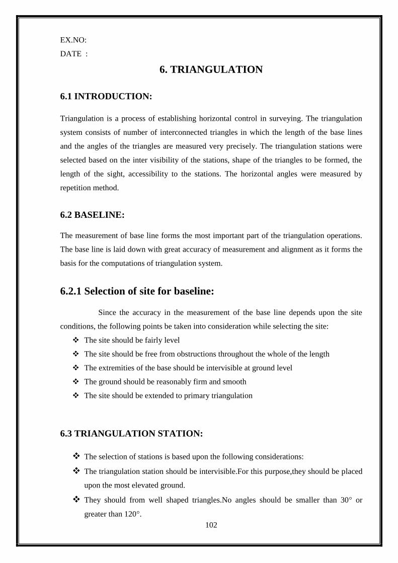
102
EX.NO:
DATE :
6. TRIANGULATION
6.1 INTRODUCTION:
Triangulation is a process of establishing horizontal control in surveying. The triangulation
system consists of number of interconnected triangles in which the length of the base lines
and the angles of the triangles are measured very precisely. The triangulation stations were
selected based on the inter visibility of the stations, shape of the triangles to be formed, the
length of the sight, accessibility to the stations. The horizontal angles were measured by
repetition method.
6.2 BASELINE:
The measurement of base line forms the most important part of the triangulation operations.
The base line is laid down with great accuracy of measurement and alignment as it forms the
basis for the computations of triangulation system.
6.2.1 Selection of site for baseline: Since the accuracy in the measurement of the base line depends upon the site
conditions, the following points be taken into consideration while selecting the site:
The site should be fairly level
The site should be free from obstructions throughout the whole of the length
The extremities of the base should be intervisible at ground level
The ground should be reasonably firm and smooth
The site should be extended to primary triangulation
6.3 TRIANGULATION STATION:
The selection of stations is based upon the following considerations:
The triangulation station should be intervisible.For this purpose,they should be placed
upon the most elevated ground.
They should from well shaped triangles.No angles should be smaller than 30° or
greater than 120°.

103
The stations should be easily accessible
They should be so selected that the length of sight is neither too small nor too large.
They should be in commanding situation.
6.4 INSTRUMENTS USED:
Theodolite : Used to focus the station and for measuring the horizontal angles
Tripodstand:The theodolite is fixed on it and leveled at the station points
Tape : It is used measure the distance of the base line
Arrows and Pegs
Ranging rods: To range the intermediate points in the survey line
6.5 ROUTINE OF TRIANGULATION SURVEY:
The routine of triangulation survey generally consists of the following operations:
Reconnaissance
Erection of signals & Towers
Measurement of baselines
Measurement of horizontal angles
Astronomical observations at Laplace stations and
Computations
6.6 RECONNAISANCE:
For triangulation, the mountable hill at karattumedu waschosen. Reconnaissance
survey at the site was done before actually starting the exercise. The easiest route for tracking
by means of transport and visibility of other stations from that particular station was ensured
and the work was planned accordingly. The base line was chosen in a farm near the S.G.I.T
campus and visibility of two other station points (a hill temple and the hilltop) was ensured
from the base stations.
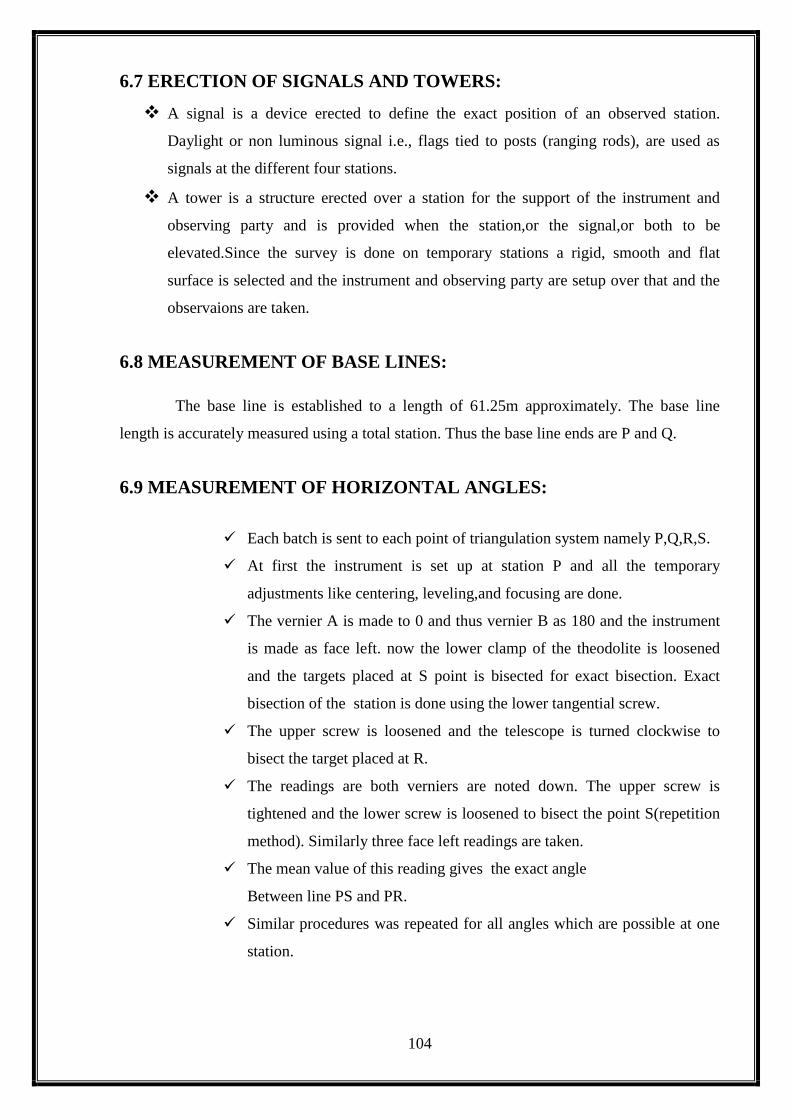
104
6.7 ERECTION OF SIGNALS AND TOWERS:
A signal is a device erected to define the exact position of an observed station.
Daylight or non luminous signal i.e., flags tied to posts (ranging rods), are used as
signals at the different four stations.
A tower is a structure erected over a station for the support of the instrument and
observing party and is provided when the station,or the signal,or both to be
elevated.Since the survey is done on temporary stations a rigid, smooth and flat
surface is selected and the instrument and observing party are setup over that and the
observaions are taken.
6.8 MEASUREMENT OF BASE LINES:
The base line is established to a length of 61.25m approximately. The base line
length is accurately measured using a total station. Thus the base line ends are P and Q.
6.9 MEASUREMENT OF HORIZONTAL ANGLES:
Each batch is sent to each point of triangulation system namely P,Q,R,S.
At first the instrument is set up at station P and all the temporary
adjustments like centering, leveling,and focusing are done.
The vernier A is made to 0 and thus vernier B as 180 and the instrument
is made as face left. now the lower clamp of the theodolite is loosened
and the targets placed at S point is bisected for exact bisection. Exact
bisection of the station is done using the lower tangential screw.
The upper screw is loosened and the telescope is turned clockwise to
bisect the target placed at R.
The readings are both verniers are noted down. The upper screw is
tightened and the lower screw is loosened to bisect the point S(repetition
method). Similarly three face left readings are taken.
The mean value of this reading gives the exact angle
Between line PS and PR.
Similar procedures was repeated for all angles which are possible at one
station.

105
Then the instrument is shifted to the other stations Q,R and S and all
intermediate angles between the station lines are observed and the
angular readings are tabulated.
6.10 ASTRONOMICAL OBSERVATIONS AT PLACE STATIONS:
Setup the theodolite at S and perform all the three temporary adjustments.
Set vernier A to read O and tighten upper clamp.
Keep face left and direct the telescope to bisect the ranging rod at P.
Now tighten the lower clamp and release the upper clamp.
Sawing the telescope and bring the image of the sun to the I – quadrant of the
cross hairs
For making the vertical and horizontal hair tangential to the image of the sun, use
the upper tangent screw and vertical circle tangent screw after tightening the upper
clamp and vertical circle clamp. Immediately note down the time, horizontal angle
and vertical angle.
Change the face and release the upper clamp and vertical circle clamp and bring
the image of the sun to the III- quadrant, making the horizontal and vertical hairs
tangential to the image of the sun. Immediately note down the time, vertical angle
and horizontal circle reading.
Average of the concerned two values gives that value corresponding to the sun.
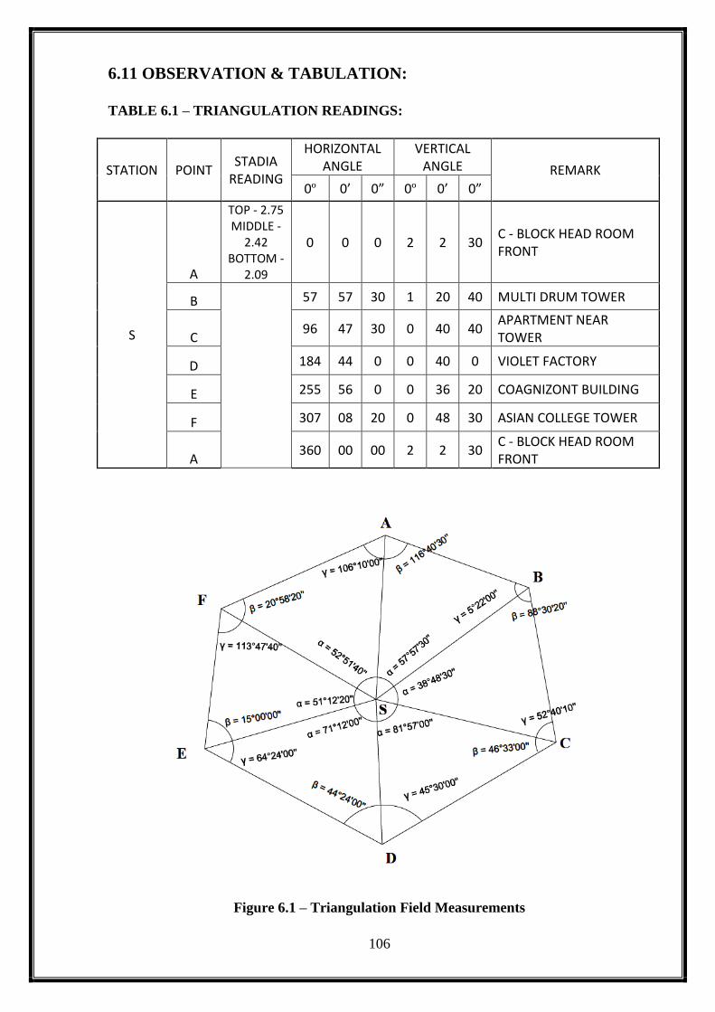
106
6.11 OBSERVATION & TABULATION:
TABLE 6.1 – TRIANGULATION READINGS:
STATION POINT STADIA
READING
HORIZONTAL ANGLE
VERTICAL ANGLE REMARK
0º 0’ 0” 0º 0’ 0”
S
A
TOP - 2.75 MIDDLE -
2.42 BOTTOM -
2.09
0 0 0 2 2 30 C - BLOCK HEAD ROOM FRONT
B
57 57 30 1 20 40 MULTI DRUM TOWER
C 96 47 30 0 40 40
APARTMENT NEAR TOWER
D 184 44 0 0 40 0 VIOLET FACTORY
E 255 56 0 0 36 20 COAGNIZONT BUILDING
F 307 08 20 0 48 30 ASIAN COLLEGE TOWER
A 360 00 00 2 2 30
C - BLOCK HEAD ROOM FRONT
Figure 6.1 – Triangulation Field Measurements

107
6.12 CALCULATIONS:
6.12.1 Base line of SA station:
SA = D = Ks cos2𝜃 + Ccos𝜃
When analytical lense is fixed
so K=100 & C = 0
D = 100x0.66xcos2 (2°02’30”)
D = 100x1.2x0.9987
D = SA = 65.92 m
Vertical distance of SA:
V =KS sin 2𝜃
2+ C sinθ
=100𝑋0.66𝑋𝑠𝑖𝑛(2𝑋2°8′00")
2
V = 2.45 m
6.12.2 To find out distance of side:
i)< 𝑆𝐴𝐵
𝑆𝐴
𝑠𝑖𝑛𝛾1=
𝑆𝐵
𝑠𝑖𝑛𝛽1=
𝐴𝐵
𝑠𝑖𝑛𝛼1
To calculate the distance of SB:
𝑆𝐴
𝑠𝑖𝑛𝛾1=
𝑆𝐵
𝑠𝑖𝑛𝛽1
SB = 65.92
sin (5°22’00”)𝑋𝑠𝑖𝑛(116°40’30”)
SB = 629.79 m
To calculate of distance of AB:
𝑆𝐴
𝑠𝑖𝑛𝛾1=
𝐴𝐵
𝑠𝑖𝑛𝛼1
AB =65.92
sin (5°22’00”)𝑋𝑠𝑖𝑛(57°57’30”)
AB = 597.44 m
α1 = 57º57’30’’
β1 = 116º40’30’’
γ1 = 05º22’00’’
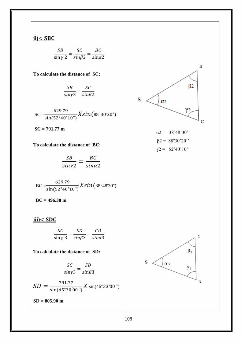
108
ii)< 𝐒𝐁𝐂
𝑆𝐵
sin 𝛾 2=
𝑆𝐶
𝑠𝑖𝑛𝛽2=
𝐵𝐶
𝑠𝑖𝑛𝛼2
To calculate the distance of SC:
𝑆𝐵
𝑠𝑖𝑛𝛾2=
𝑆𝐶
𝑠𝑖𝑛𝛽2
SC =629.79
sin (52°40’10”)𝑋𝑠𝑖𝑛(88°30′20")
SC = 791.77 m
To calculate the distance of BC:
𝑆𝐵
𝑠𝑖𝑛𝛾2=
𝐵𝐶
𝑠𝑖𝑛𝛼2
BC =629.79
sin (52°40’10”)𝑋𝑠𝑖𝑛(38°48'30'')
BC = 496.38 m
iii)< 𝐒𝐃𝐂
𝑆𝐶
sin 𝛾 3=
𝑆𝐷
𝑠𝑖𝑛𝛽3=
𝐶𝐷
𝑠𝑖𝑛𝛼3
To calculate the distance of SD:
𝑆𝐶
𝑠𝑖𝑛𝛾3=
𝑆𝐷
𝑠𝑖𝑛𝛽3
𝑆𝐷 =791.77
sin (45°30′00”)𝑋 sin(46°33′00”)
SD = 805.90 m
α2 = 38º48’30’’
β2 = 88º30’20’’
γ2 = 52º40’10’’

109
To calculate the distance of CD:
𝑆𝐶
𝑠𝑖𝑛𝛾3=
𝐶𝐷
𝑠𝑖𝑛𝛼3
𝐶𝐷 =791.77
sin (45°30′30”)𝑋 sin(81°57’0”)
CD = 1109.38 m
iv)< 𝐒𝐃𝐄
𝑆𝐷
sin 𝛾 4=
𝑆𝐸
𝑠𝑖𝑛𝛽4=
𝐷𝐸
𝑠𝑖𝑛𝛼4
To calculate the distance of SE:
𝑆𝐷
𝑠𝑖𝑛𝛾4=
𝑆𝐸
𝑠𝑖𝑛𝛽4
𝑆𝐸 =805.90
sin (64°24′00”)𝑋 sin(44°24′00”)
SE = 625.24 m
To calculate the distance of DE:
𝑆𝐷
𝑠𝑖𝑛𝛾4=
𝐷𝐸
𝑠𝑖𝑛𝛼4
𝐷𝐸 =805.90
sin (64°24′00”)𝑋 sin(71°12′00”)
DE = 845.95m
v)< 𝐒𝐄𝐅
𝑆𝐸
sin 𝛾 5=
𝑆𝐹
𝑠𝑖𝑛𝛽5=
𝐸𝐹
𝑠𝑖𝑛𝛼5
To calculate the distance of SF:
𝑆𝐸
𝑠𝑖𝑛𝛾5=
𝑆𝐹
𝑠𝑖𝑛𝛽5
α3 = 81º57’00’’
β3 = 46º33’00’’
γ3 = 45º30’30’’
α4 = 71º12’00’’
β4 = 44º24’00’’
γ4 = 64º24’00’’
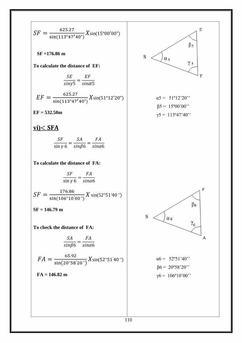
110
𝑆𝐹 =625.27
sin (113°47′40”)𝑋sin(15°00′00”)
SF =176.86 m
To calculate the distance of EF:
𝑆𝐸
𝑠𝑖𝑛𝛾5=
𝐸𝐹
𝑠𝑖𝑛𝛼5
𝐸𝐹 =625.27
sin (113°47′40”)𝑋sin(51°12′20”)
EF = 532.58m
vi)< 𝐒𝐅𝐀
𝑆𝐹
sin 𝛾 6=
𝑆𝐴
𝑠𝑖𝑛𝛽6=
𝐹𝐴
𝑠𝑖𝑛𝛼6
To calculate the distance of FA:
𝑆𝐹
sin 𝛾 6=
𝐹𝐴
𝑠𝑖𝑛𝛼6
𝑆𝐹 =176.86
sin (106°10′00”)𝑋 sin(52°51′40”)
SF = 146.79 m
To check the distance of FA:
𝑆𝐴
𝑠𝑖𝑛𝛽6=
𝐹𝐴
𝑠𝑖𝑛𝛼6
𝐹𝐴 =65.92
sin(20°58′20”)𝑋sin(52°51′40”)
FA = 146.82 m
α5 = 51º12’20’’
β5 = 15º00’00’’
γ5 = 113º47’40’’
α6 = 52º51’40’’
β6 = 20º58’20’’
γ6 = 106º10’00’’

111
6.12.3 Area Calculating:
Formulas:
Area, A =√𝑠(𝑠 − 𝑎)(𝑠 − 𝑏)(𝑠 − 𝑐)
Where, S =𝑎+𝑏+𝑐
2
𝐢) < 𝐒𝐀𝐁
S = 𝑎+𝑏+𝑐
2
= 65.92+629.79+597.44
2
S = 646.58 m
A =√𝑠(𝑠 − 𝑎)(𝑠 − 𝑏)(𝑠 − 𝑐)
A =√646.58(579.66𝑋15.79𝑋48.14)
Area of SAB = 17600.01 m2
Area of SAB = 4.35 Acre
Area of SAB = 1.760 Hectare
𝐢𝐢) < 𝐒𝐁𝐂
S = 𝑎+𝑏+𝑐
2
= 629.79+791.77+496.38
2
S = 958.97 m
A =√𝑠(𝑠 − 𝑎)(𝑠 − 𝑏)(𝑠 − 𝑐)
A =√958.97(329.18𝑋167.2𝑋462.59)
a = SA = 65.92 m
b = SB = 629.79 m
c = AB = 594.44 m
a = SB = 629.79 m
b = SC = 791.77 m
c = BC = 496.38 m

112
Area of SBC = 156255.56 m2
Area of SBC = 38.61 Acre
Area of SBC = 15.625 Hectare
𝐢𝐢𝐢) < 𝐒𝐂𝐃
S = 𝑎+𝑏+𝑐
2
= 791.77+805.90+1109.38
2
S = 1353.53 m
A =√𝑠(𝑠 − 𝑎)(𝑠 − 𝑏)(𝑠 − 𝑐)
A =√1353.53(561.76𝑋547.63𝑋244.15)
Area of SCD = 318846.26 m2
Area of SCD = 78.79 Acre
Area of SCD = 31.885 Hectare
𝐢𝐯) < 𝑆𝐷𝐸
S = 𝑎+𝑏+𝑐
2
= 805.9+625.24+845.95
2
S = 1138.55 m
A =√𝑠(𝑠 − 𝑎)(𝑠 − 𝑏)(𝑠 − 𝑐)
A =√1138.55(332.65𝑋513.31𝑋845.95)
Area of SDE = 238504.64 m2
Area of SDE = 58.94 Acre
Area of SDE = 23.850 Hectare
a = SC = 791.77 m
b = SD = 805.90 m
c = CD = 1109.38 m
a = SD = 805.90 m
b = SE = 625.24 m
c = DE = 845.95 m

113
𝐯) < 𝐒𝐄𝐅
S = 𝑎+𝑏+𝑐
2
= 625.24+176.86+532.58
2
S = 667.34 m
A =√𝑠(𝑠 − 𝑎)(𝑠 − 𝑏)(𝑠 − 𝑐)
A =√667.34(42.10𝑋490.48𝑋134.76)
Area of SEF = 43092.91 m2
Area of SEF = 10.65 Acre
Area of SEF = 4.309 Hectare
𝐯𝐢)< 𝑆𝐹𝐴
S = 𝑎+𝑏+𝑐
2
= 176.86+65.92+146.79
2
S = 194.79 m
A =√𝑠(𝑠 − 𝑎)(𝑠 − 𝑏)(𝑠 − 𝑐)
A =√194.79(17.93𝑋128.87𝑋48.00)
Area of SFA = 4608.64 m2
Area of SFA = 1.15 Acre
Area of SFA = 0.465 Hectare
a = SD = 625.24 m
b = SE = 176.86 m
c = DE = 532.58 m
a = SD = 176.86 m
b = SE = 65.92 m
c = DE = 146.79 m

114
Total Area = SAB+SBC+SCD+SDE+SEF+SFA
= 4.35+38.61+78.79+58.94+10.65+1.15
Total Area = 192.47Acre
iv) Area = 192.47 Acre
v) Area = 778908.11 m2
vi) Area = 77.89 Hectare
6.13 RESULTS:
Length of the sides of triangles:
TABLE 6.2 – TRIANGULATION RESULT
SA = 65.92 m AB = 597.44 m
SB = 629.79 m BC = 496.38 m
SC = 791.77 m CD = 1109.38 m
SD = 805.90 m DE = 845.95 m
SE = 625.24 m EF = 532.58 m
SF =176.86 m FA = 146.79 m
TOTAL AREA = 192.47Acre
= 778908.11 m2
= 77.89 Hectare
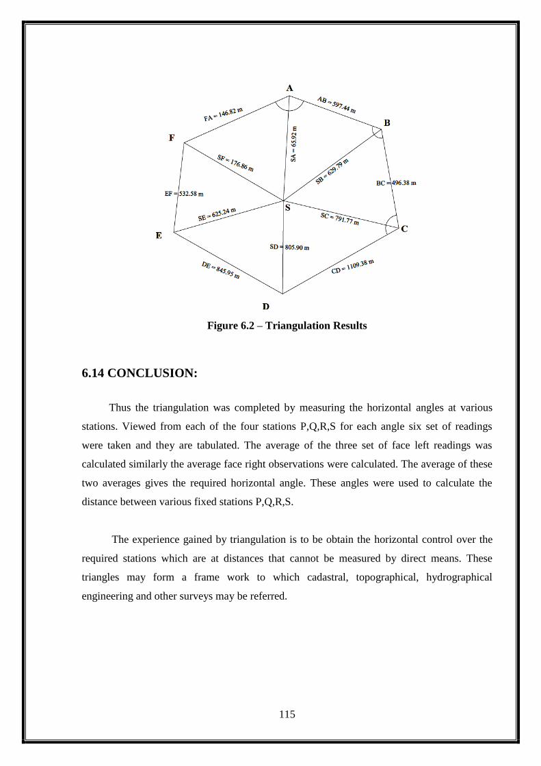
115
Figure 6.2 – Triangulation Results
6.14 CONCLUSION:
Thus the triangulation was completed by measuring the horizontal angles at various
stations. Viewed from each of the four stations P,Q,R,S for each angle six set of readings
were taken and they are tabulated. The average of the three set of face left readings was
calculated similarly the average face right observations were calculated. The average of these
two averages gives the required horizontal angle. These angles were used to calculate the
distance between various fixed stations P,Q,R,S.
The experience gained by triangulation is to be obtain the horizontal control over the
required stations which are at distances that cannot be measured by direct means. These
triangles may form a frame work to which cadastral, topographical, hydrographical
engineering and other surveys may be referred.
116
7. RADIAL CONTOURING

117
EX.NO:
DATE:
7. RADIAL CONTOURING
7.1 INTRODUCTION:
Contouring is a method of representing the ground surface from using contour
lines. The radial contouring is the method by which intermediate points are taken on the
radial lines whose reduced levels are used to draw the contour maps. The radial lines are
those lines which radiate from a fixed point with some uniform angle (30°). The leveling staff
is held at various points on the radial lines and the staff readings are noted. From those, the
reduced levels can be determined.
7.2 INSTRUMENTS USED:
Theodolite and tripod:
The theodolite is used here for angular spacing of the radial lines and for
reading staff.
Levelling staff:
Leveling staff of 0.005m least count is used to deduce the
R.L.of the points.
7.3 RECONNAISSANCE:
The area given to us was a small hill. We can get the contour lines at some
particular intervals. During the survey, we decided that where the instrument should be
placed and which direction the staff man should go along the radial lines.
7.4 PROCEDURE:
The transit theodolite,is placed exactly over the station point
The temporary adjustment namely centering,leveling,focusing the eye
piece and the object glass are done perfectly.
The staff reading over the bench mark is noted down.
The vernier face are adjusted such that vernier A line.
The upper,middle and the lower hair readings are noted down and the
vertical angles if necessary.

118
Similarly various readings are observed along the same line and by
varying the distances approximately at equal intervals.
The telescope is turned clockwise by 30° and focused along B line: the
same procedure is repeated.
Using the above observations, the distance between the instrument
station and the staff station and the R.L. of all points are calculated and
the contours are plotted.
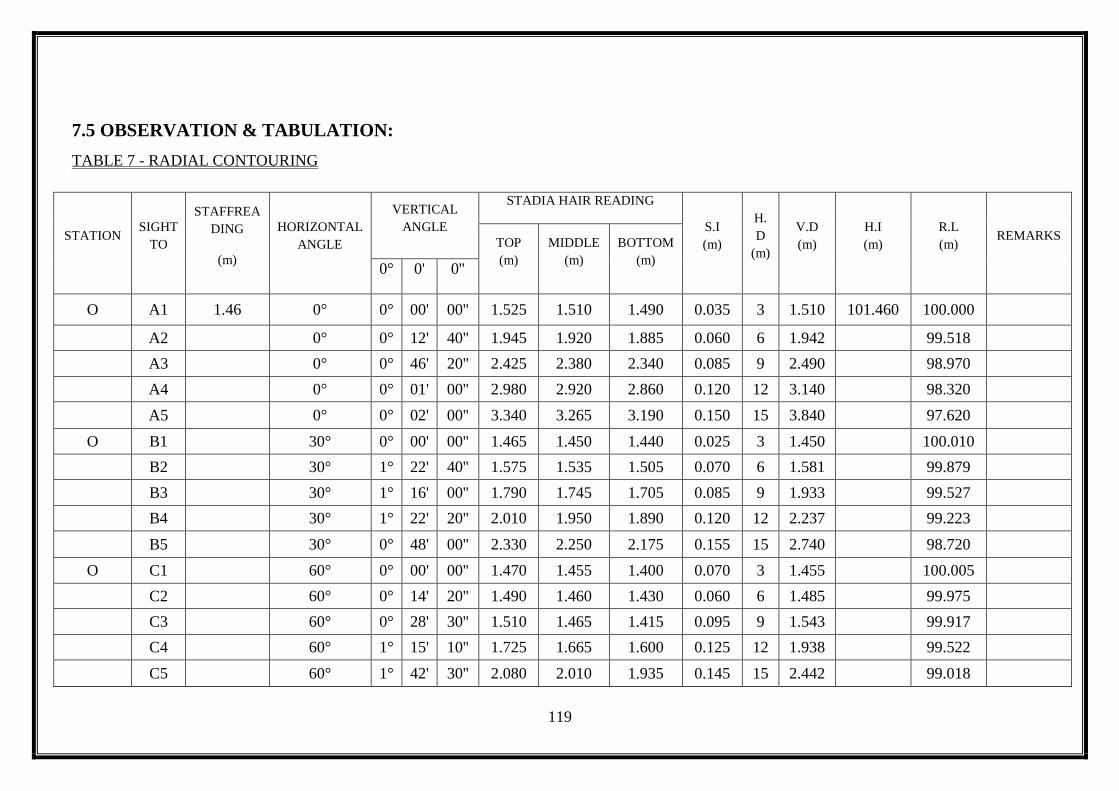
119
7.5 OBSERVATION & TABULATION:
TABLE 7 - RADIAL CONTOURING
STATION SIGHT
TO
STAFFREA
DING
(m)
HORIZONTAL
ANGLE
VERTICAL
ANGLE
STADIA HAIR READING
S.I
(m)
H.
D
(m)
V.D
(m)
H.I
(m)
R.L
(m) REMARKS
TOP
(m)
MIDDLE
(m)
BOTTOM
(m) 0° 0' 0''
O A1 1.46 0° 0° 00' 00'' 1.525 1.510 1.490 0.035 3 1.510 101.460 100.000
A2
0° 0° 12' 40'' 1.945 1.920 1.885 0.060 6 1.942
99.518
A3
0° 0° 46' 20'' 2.425 2.380 2.340 0.085 9 2.490
98.970
A4
0° 0° 01' 00'' 2.980 2.920 2.860 0.120 12 3.140
98.320
A5
0° 0° 02' 00'' 3.340 3.265 3.190 0.150 15 3.840
97.620
O B1
30° 0° 00' 00'' 1.465 1.450 1.440 0.025 3 1.450
100.010
B2
30° 1° 22' 40'' 1.575 1.535 1.505 0.070 6 1.581
99.879
B3
30° 1° 16' 00'' 1.790 1.745 1.705 0.085 9 1.933
99.527
B4
30° 1° 22' 20'' 2.010 1.950 1.890 0.120 12 2.237
99.223
B5
30° 0° 48' 00'' 2.330 2.250 2.175 0.155 15 2.740
98.720
O C1
60° 0° 00' 00'' 1.470 1.455 1.400 0.070 3 1.455
100.005
C2
60° 0° 14' 20'' 1.490 1.460 1.430 0.060 6 1.485
99.975
C3
60° 0° 28' 30'' 1.510 1.465 1.415 0.095 9 1.543
99.917
C4
60° 1° 15' 10'' 1.725 1.665 1.600 0.125 12 1.938
99.522
C5
60° 1° 42' 30'' 2.080 2.010 1.935 0.145 15 2.442
99.018

120
STATION SIGHT
TO
STAFF
READING
(m)
HORIZONTAL
ANGLE
VERTICAL
ANGLE
STADIA HAIR READING
S.I
(m)
H.D
(m)
V.D
(m)
H.I
(m)
R.L
(m) REMARKS
TOP
(m)
MIDDLE
(m)
BOTTOM
(m) 0° 0' 0''
O D1
90° 0° 00' 00' 1.630 1.620 1.605 0.025 3 1.620
99.840
D2
90° 0° 20' 30'' 2.160 2.130 2.100 0.060 6 2.165
99.295
D3
90° 0° 48' 00'' 2.585 2.540 2.495 0.090 9 2.665
98.795
D4
90° 1° 36' 30'' 3.175 3.115 3.055 0.120 12 3.452
98.008
D5
90° 1° 04' 30'' 3.735 3.660 3.585 0.150 15 4.203
97.257
O E1
120° 0° 00' 00'' 1.785 1.770 1.755 0.030 3 1.770
99.690
E2
120° 0° 29' 40'' 2.535 2.505 2.475 0.060 6 2.557
98.903
E3
120° 0° 58' 20'' 3.210 3.165 3.120 0.090 9 3.318
98.142
E4
120° 1° 30' 00'' 3.680 3.620 3.560 0.120 12 3.934
97.526
E5
120° 1° 42' 00'' 3.945 3.860 3.795 0.150 15 4.305
97.155
O F1
150° 0° 00' 00'' 1.950 1.935 1.920 0.030 3 1.935
99.525
F2
150° 0° 22' 00' 2.315 2.270 2.225 0.090 6 2.383
99.077
F3
150° 0° 43' 20'' 2.600 2.570 2.540 0.060 9 2.610
98.850
F4
150° 1° 04' 30'' 3.615 3.595 3.495 0.120 12 3.820
97.640
F5
150° 1° 48' 30'' 3.735 3.665 3.590 0.145 15 4.122
97.338
O G1
180° 0° 00' 00' 1.760 1.730 1.690 0.070 3 1.730
99.730
G2
180° 0° 14' 20'' 2.400 2.350 2.250 0.150 6 2.413
99.047
G3
180° 0° 52' 30'' 3.000 2.850 2.700 0.300 9 3.310
98.150
G4
180° 1° 22' 00'' 3.440 3.290 3.100 0.340 12 4.100
97.360
G5
180° 1° 40 40'' 3.700 3.490 3.260 0.440 15 4.769
96.691
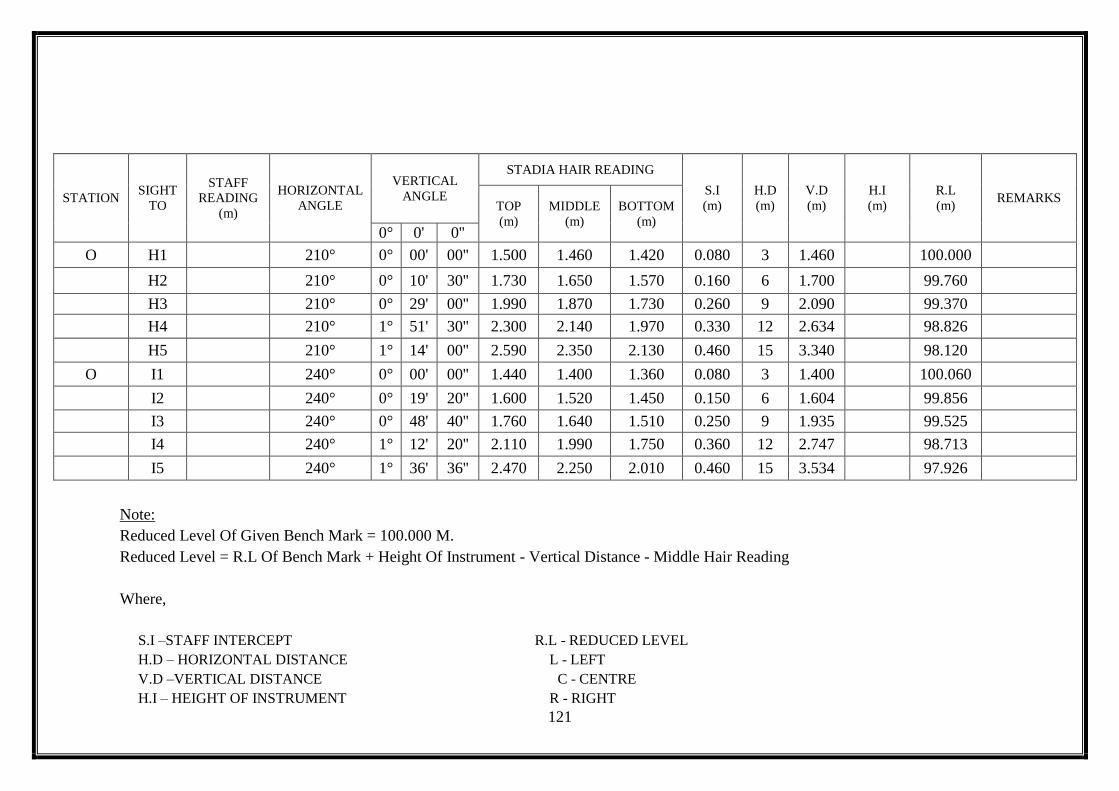
121
STATION SIGHT
TO
STAFF
READING
(m)
HORIZONTAL
ANGLE
VERTICAL
ANGLE
STADIA HAIR READING
S.I
(m)
H.D
(m)
V.D
(m)
H.I
(m)
R.L
(m) REMARKS
TOP
(m)
MIDDLE
(m)
BOTTOM
(m) 0° 0' 0''
O H1
210° 0° 00' 00'' 1.500 1.460 1.420 0.080 3 1.460
100.000
H2
210° 0° 10' 30'' 1.730 1.650 1.570 0.160 6 1.700
99.760
H3
210° 0° 29' 00'' 1.990 1.870 1.730 0.260 9 2.090
99.370
H4
210° 1° 51' 30'' 2.300 2.140 1.970 0.330 12 2.634
98.826
H5
210° 1° 14' 00'' 2.590 2.350 2.130 0.460 15 3.340
98.120
O I1
240° 0° 00' 00'' 1.440 1.400 1.360 0.080 3 1.400
100.060
I2
240° 0° 19' 20'' 1.600 1.520 1.450 0.150 6 1.604
99.856
I3
240° 0° 48' 40'' 1.760 1.640 1.510 0.250 9 1.935
99.525
I4
240° 1° 12' 20'' 2.110 1.990 1.750 0.360 12 2.747
98.713
I5
240° 1° 36' 36'' 2.470 2.250 2.010 0.460 15 3.534
97.926
Note:
Reduced Level Of Given Bench Mark = 100.000 M.
Reduced Level = R.L Of Bench Mark + Height Of Instrument - Vertical Distance - Middle Hair Reading
Where,
S.I –STAFF INTERCEPT R.L - REDUCED LEVEL
H.D – HORIZONTAL DISTANCE L - LEFT
V.D –VERTICAL DISTANCE C - CENTRE
H.I – HEIGHT OF INSTRUMENT R - RIGHT

122
7.6 RESULT:
Thus the staff readings and the R.L. of the intermediate points calculated are tabulated.
The radial lines were connected with an angular spacing of 30°, starting from 0º to 360°. Smooth
curves of various contour lines were drawn connecting points of equal elevation and the contour map
is prepared.
7.7 CONCLUSION:
The contour lines joining the point of equal elevation represented in the contour map
can be used for selecting the appropriate route for the highway alignment and to determine the
quantity of earthwork to be involved in the respective projects etc.

123
8. DETERMINATION OF THE
AZIMUTH OF A SURVEY LINE BY
OBSERVATION ON THE SUN

124
EX NO :
DATE:
8. DETERMINATION OF THE AZIMUTH OF A SURVEY LINE BY
OBSERVATION ON THE SUN
8.1 AIM:
To determine the azimuth of the given survey line.
8.2APPARATUS REQUIRED:
Azimuth is the horizontal angle, a celestial body makes with the pole.
8.3 PROCEDURE:
1. Set the instruments over the station mark and level it accurately.
2. Clamp both the plates to zero and sight to reference mark (R.M).
3. Turn to the sun observe altitude and horizontal angle with sun in quadrant of cross wire
system. The motion in the azimuth is slow and vertical hair is kept in contact by the upper
screw (slow motion),the sun being allowed to make contact with the horizontal hair. The
time of observation is also noted.
4. Using the two tangent screws as quickly as possible being the sun into quadrant III of the
cross wire and again read the horizontal and vertical angle. Observe also the chronometer
time.
5. Turn to RM, reverse the face and take another sight on RM.
6. Take two more observation of the sun precisely in the same way as in steps 3&4, but this
time sun is in quadrant II&IV. Note the time of each observation.
7. Finally bisect the RM to see the reading is zero.
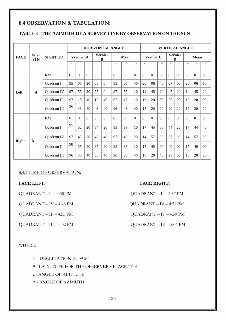
125
8.4 OBSERVATION & TABULATION:
TABLE 8 - THE AZIMUTH OF A SURVEY LINE BY OBSERVATION ON THE SUN
8.4.1 TIME OF OBSERVATION:
FACE LEFT: FACE RIGHT: QUADRANT – I - 4:30 PM QUADRANT – I - 4:37 PM QUADRANT – IV – 4:48 PM QUADRANT – IV – 4:51 PM QUADRANT – II – 4:55 PM QUADRANT – II – 4:59 PM QUADRANT – III – 5:02 PM QUADRANT – III – 5:04 PM
WHERE,
δ - DECLINATION IN 39 ̊ 26'
𝜃- LATTITUTE FOR THE OBSERVER'S PLACE 11 ̊ 01'
α - ANGLE OF ALTITUTE
A - ANGLE OF AZIMUTH
FACE INST
.STN SIGHT TO
HORIZONTAL ANGLE VERTICAL ANGLE
Vernier A Vernier
B Mean Vernier C
Vernier
D Mean
° ' '' ' '' ° ' '' ° ' '' ' '' ° ' ''
Left A
RM 0 0 0 0 0 0 0 0 0 0 0 0 0 0 0 0
Quadrant I 95 05 20 06 0 95 05 40 20 06 40 07 00 20 06 50
Quadrant IV 97 55 20 55 0 97 55 10 14 45 20 45 20 14 45 20
Quadrant II 97 13 40 12 40 97 13 10 15 20 00 20 00 15 20 00
Quadrant III 96
43 40 43 40 96 43 40 17 20 20 20 20 17 20 20
Right
B
B
RM 0 0 0 0 0 0 0 0 0 0 0 0 0 0 0 0
Quadrant I 95
52 20 54 20 95 53 10 17 45 00 44 20 17 44 40
Quadrant IV 97 45 20 45 40 97 45 20 14 57 00 57 00 14 57 00
Quadrant II 98
35 40 35 20 98 35 10 17 40 00 40 00 17 40 00
Quadrant III 96 30 40 30 40 96 30 40 18 20 40 20 00 18 20 20

126
8.5 CALCULATIONS:
cos 𝐴 =𝑠𝑖𝑛𝛿 − 𝑠𝑖𝑛𝜃𝑠𝑖𝑛𝛼
𝑐𝑜𝑠𝛼𝑐𝑜𝑠𝜃
𝛼= 2 𝑄𝐼 +2 𝑄 𝐼𝐼𝐼
2
Face Left:
α= 2 X 20°06′ 50"+2 X 17°20′20"
2= 37°27′10"
cos A =sin39°26′ − sin37°27′10"sin11°1′
cos37°27′10" cos11°1′
A = 48°𝟏𝟒′𝟐𝟑. 𝟕𝟕"
α= 2 X 14°14′ 45"+2 X 15°20′00"
2= 30°05′20"
cos A =sin39°26′ − sin30°05′20"sin11°1′
cos30°05′20" cos11°1′
A = 50°𝟑𝟒′𝟐𝟔. 𝟓𝟖"
Face Right:
α= 2 X 17°44′ 40"+2 X 18°20′20"
2= 36°05′00"
cos A =sin39°26′ − sin36°05′10"sin11°1′
cos35°25′00" cos11°1′
A = 49°𝟏𝟐′𝟐𝟐. 𝟐"

127
α= 2 X 14°57′ 00"+2 X 17°40′00"
2=32°37′00"
cos A =sin39°26′ − sin32°37′55"sin11°1′
cos32°37′00" cos11°1′
A = 49°𝟓𝟓′𝟓𝟗. 𝟕𝟗"
Mean Azimuth =48°32′50.7"+50°34'26.6"+49°01′57.65"+49°55′44.36"
4
A = 49°𝟐𝟗′𝟏𝟖. 𝟎𝟗"
SUN
49°29'18.09"
N
E
S
W
8.6 RESULT:
Azimuth of the line, A = 49°29'18.09''