cjp2-cjp cat en - smc etech · series cjp2/cjp pin cylinders cat.eus20-194a-uk ø2 one-touch...
TRANSCRIPT
Series CJP2/CJP
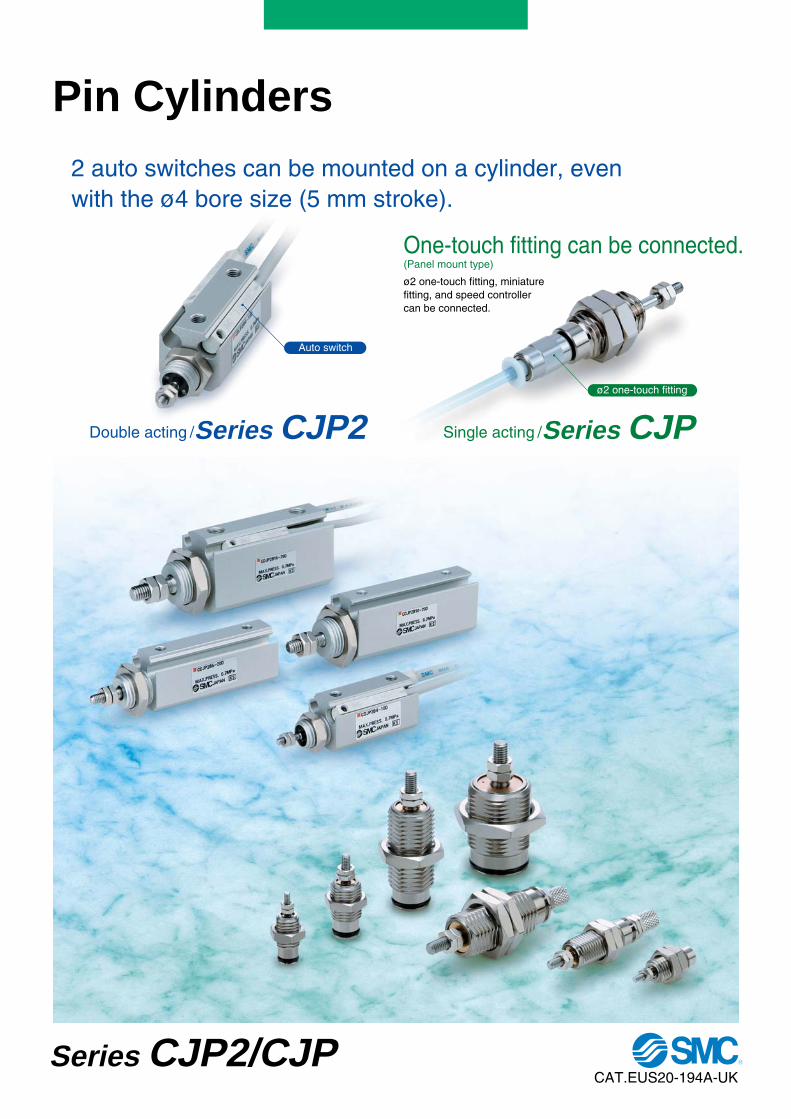
Pin Cylinders
CAT.EUS20-194A-UK
ø2 one-touch fitting
Auto switch
Double acting /Series CJP2 Single acting /Series CJP
2 auto switches can be mounted on a cylinder, evenwith the ø4 bore size (5 mm stroke).
One-touch fitting can be connected.(Panel mount type)
ø2 one-touch fitting, miniaturefitting, and speed controllercan be connected.
StrokeBore size (mm)
510152025303540
411131517————
61618212325———
102729323537404345
164246505458636771
Unit: g
Bore size
4
6
10
16
B
14
14
15
20
A
29 + stroke(34 + stroke)
33 + stroke(38 + stroke)
39.5 + stroke(44.5 + stroke)
43.5 + stroke(48.5 + stroke)
C
14.5
16.5
19
24.5
Unit: mmDimensions Weight
A
C
B(CDJP2B4-10D)
* ( ): Dimension for built-in magnet type
Note 1) A stroke of 20 is available with a standard product only. Note 2) Bore size of ø4 is available with basic mounting only.
B
CA
B
CA
Panel mount type (CJPB4-5) Embedded type (CJPS4-5)
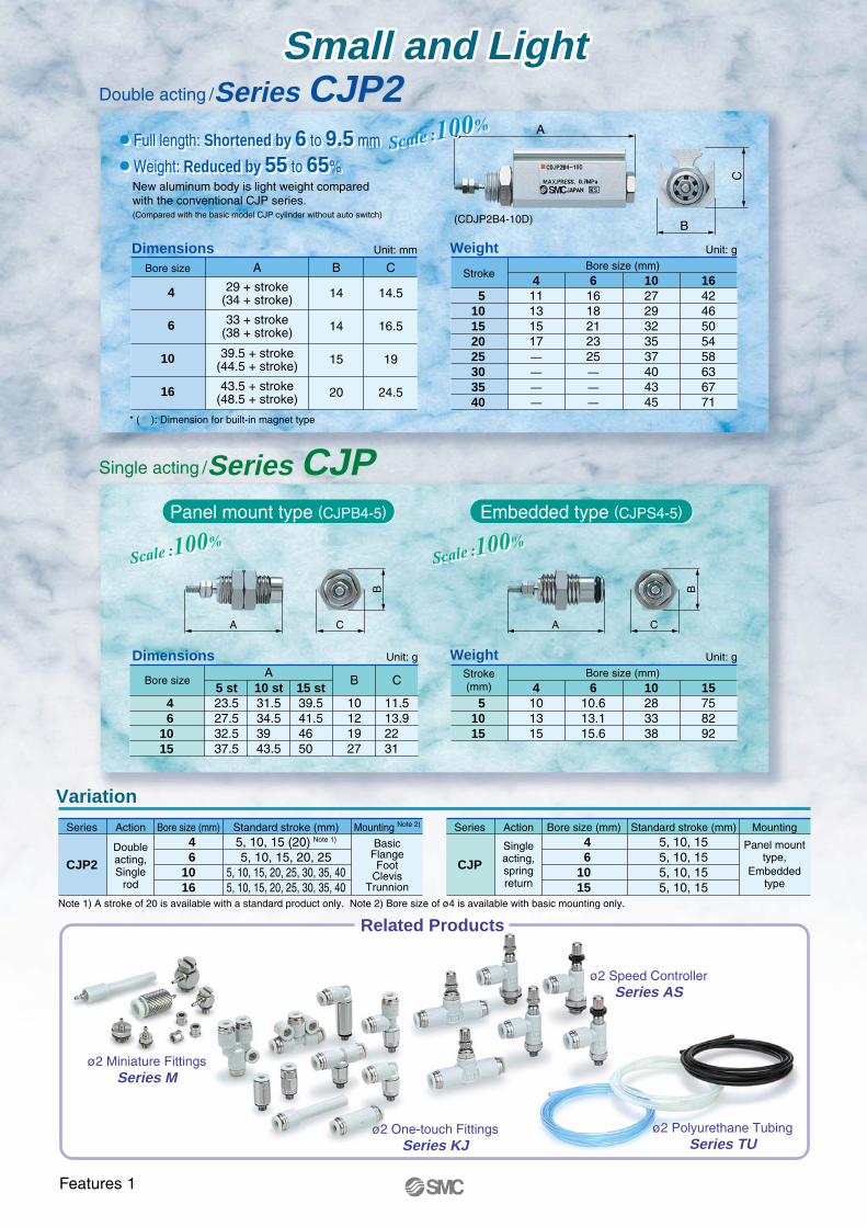
Double acting /Series CJP2
Stroke(mm)
Bore size (mm)
51015
4101315
610.613.115.6
10283338
15758292
Unit: g
Bore sizeA
46
1015
5 st23.527.532.537.5
10 st31.534.539 43.5
15 st39.541.546 50
B
10121927
C
11.513.922 31
Unit: g
Series
CJP2
Action
Doubleacting,Single
rod
Mounting Note 2)
BasicFlangeFoot
ClevisTrunnion
Bore size (mm) 4 61016
Standard stroke (mm)5, 10, 15 (20) Note 1)
5, 10, 15, 20, 255, 10, 15, 20, 25, 30, 35, 405, 10, 15, 20, 25, 30, 35, 40
Series
CJP
Action
Singleacting,springreturn
MountingBore size (mm) 4 61015
Standard stroke (mm)5, 10, 155, 10, 155, 10, 155, 10, 15
Dimensions Weight
Single acting /Series CJP
Variation
Scale :100%
Scale :100%
Scale :100%
Scale :100%
Scale :100%
Scale :100%
Small and LightSmall and Light
ø2 One-touch FittingsSeries KJ
ø2 Miniature FittingsSeries M
ø2 Polyurethane TubingSeries TU
ø2 Speed ControllerSeries AS
Related Products
Full length: Shortened by 6 to 9.5 mm Weight: Reduced by 55 to 65%
Full length: Shortened by 6 to 9.5 mm Weight: Reduced by 55 to 65%
New aluminum body is light weight compared with the conventional CJP series. (Compared with the basic model CJP cylinder without auto switch)
Panel mounttype,
Embeddedtype
Features 1
1
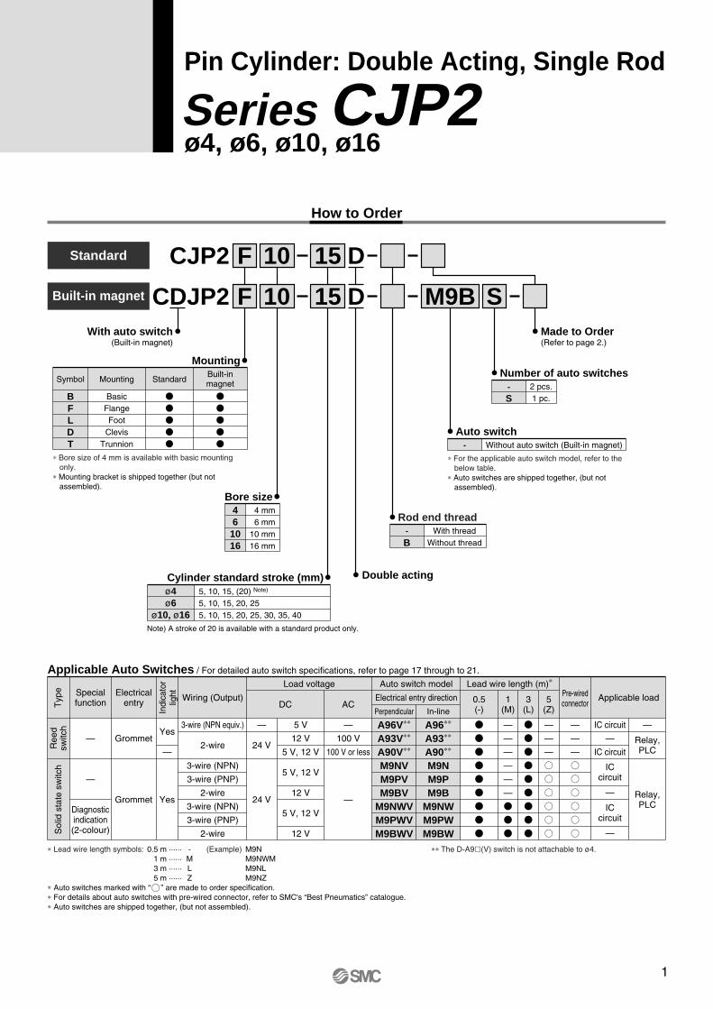
Pin Cylinder: Double Acting, Single Rod
ø4, ø6, ø10, ø16Series CJP2
CJP2 10Standard
Built-in magnet
F 15
CDJP2 F 10 15
D
D M9BWith auto switch
(Built-in magnet)
Double acting
S
BFLDT
BasicFlangeFoot
ClevisTrunnion
Mounting StandardBuilt-inmagnetSymbol
Mounting
461016
4 mm6 mm
10 mm16 mm
Bore size
ø4ø6
ø10, ø16
5, 10, 15, (20) Note)
5, 10, 15, 20, 255, 10, 15, 20, 25, 30, 35, 40
Cylinder standard stroke (mm)
Note) A stroke of 20 is available with a standard product only.
-B
With threadWithout thread
Rod end thread
- Without auto switch (Built-in magnet)
Auto switch
∗ For the applicable auto switch model, refer to the below table.
∗ Auto switches are shipped together, (but not assembled).
∗ Bore size of 4 mm is available with basic mounting only.
∗ Mounting bracket is shipped together (but not assembled).
-S
2 pcs.1 pc.
Number of auto switches
How to Order
Made to Order (Refer to page 2.)
∗ Lead wire length symbols: 0.5 m ······ - (Example) M9N1 m ······ M M9NWM3 m ······ L M9NL5 m ······ Z M9NZ
∗ Auto switches marked with “ ” are made to order specification.∗ For details about auto switches with pre-wired connector, refer to SMC's “Best Pneumatics” catalogue.∗ Auto switches are shipped together, (but not assembled).
∗∗ The D-A9(V) switch is not attachable to ø4.
Applicable Auto Switches / For detailed auto switch specifications, refer to page 17 through to 21.
Specialfunction Wiring (Output)
Load voltage
DC AC
Auto switch model
Electrical entry direction
Perpendicular In-line
Lead wire length (m)∗
0.5(-)
3(L)
5(Z)
Applicable loadPre-wiredconnector
IC circuit
IC circuit
ICcircuit
ICcircuit
Relay,PLC
Relay,PLC
1(M)
A96∗∗
A93∗∗
A90∗∗
M9NM9PM9B
M9NWM9PWM9BW
A96V∗∗
A93V∗∗
A90V∗∗
M9NVM9PVM9BV
M9NWVM9PWVM9BWV
5 V
12 V
5 V, 12 V
5 V, 12 V
12 V
5 V, 12 V
12 V
24 V
100 V
100 V or less
3-wire (NPN equiv.)
2-wire
3-wire (NPN)
3-wire (PNP)
2-wire
3-wire (NPN)
3-wire (PNP)
2-wire
Yes
YesGrommet
—
—
—
Electricalentry
Diagnosticindication(2-colour)
Grommet
Typ
e
Indi
cato
rlig
ht
Ree
dsw
itch
Sol
id s
tate
sw
itch
24 V
2
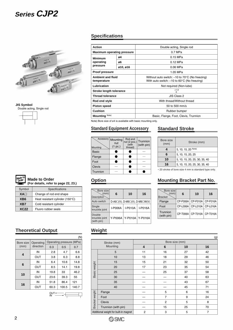
Specifications
Standard Equipment Accessory
Action
Maximum operating pressure
Proof pressure
Minimum operating pressure
Lubrication
Stroke length tolerance
Thread tolerance
Rod end style
Piston speed
Cushion
Mounting Note)
Note) Bore size of ø4 is available with basic mounting only.
Ambient and fluid temperature
Double acting, Single rod
0.7 MPa
0.15 MPa
0.12 MPa
0.06 MPa
1.05 MPa
Not required (Non-lube)
JIS Class 2
With thread/Without thread
50 to 500 mm/s
Rubber bumper
Basic, Flange, Foot, Clevis, Trunnion
+1.00
Without auto switch: –10 to 70°C (No freezing)With auto switch: –10 to 60°C (No freezing)
ø4
ø6
ø10, ø16
Accessory Mountingnut
(1 pc.)Mounting
Basic
Flange
Foot
Clevis
Trunnion
Rod endnut (2 pcs.)
(withthread)
Trunnion(with pin)
Standard Stroke
∗ 20 stroke of bore size 4 mm is standard type only.
Bore size(mm) Stroke (mm)
4
6
10
16
5, 10, 15, 20 Note)
5, 10, 15, 20, 25
5, 10, 15, 20, 25, 30, 35, 40
5, 10, 15, 20, 25, 30, 35, 40
Mounting Bracket Part No.Option
Bore size(mm)
Description6
Auto switch D-A9(V), D-M9(V), D-M9W(V)
Single knuckle joint
Double knuckle joint(with pin)
I-P006A
Y-P006A
10
I-P010A
Y-P010A
16
I-P016A
Y-P016A
Bore size(mm)
Bracket6
CP-F006A
CP-L006A
CP-T006A
10
CP-F010A
CP-L010A
CP-T010A
16
CP-F016A
CP-L016A
CP-T016A
Flange
Foot
Trunnion(with pin)
Weight(g)
Stroke (mm)Mounting
Bore size (mm)
4
5
10
15
20
25
30
35
40
Flange
Foot
Clevis
Trunnion (with pin)
Additional weight for built-in magnet
11
13
15
17
—
—
—
—
—
—
—
—
2
6
16
18
21
23
25
—
—
—
5
7
2
15
3
10
27
29
32
35
37
40
43
45
6
9
5
25
5
16
42
46
50
54
58
63
67
71
16
24
8
70
7
JIS Symbol Double acting, Single rod
OUTIN
Made to Order(For details, refer to page 22, 23.)
Symbol Specifications
Change of rod end shape
Heat resistant cylinder (150°C)
Cold resistant cylinder
Fluoro rubber seals
XAXB6
XB7
XC22
Theoretical Output(N)
Operatingdirection
Operating pressure (MPa)
0.3 0.5 0.7
Bore size(mm)
4
6
10
16
IN
OUT
IN
OUT
IN
OUT
IN
OUT
2.8
3.8
6.4
8.5
19.8
23.6
51.8
60.3
4.7
6.3
10.6
14.1
33
39.3
86.4
100.5
6.6
8.8
14.8
19.8
46.2
55
121
140.7
Bas
ic w
eigh
tB
rack
et w
eigh
t
Series CJP2
3
4
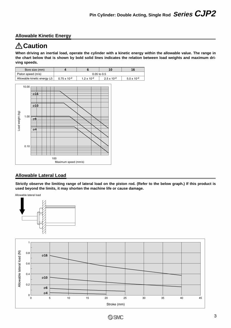
0.75 x 10⁻²
6
1.2 x 10⁻²
10
2.5 x 10⁻²
16
5.0 x 10⁻²
Bore size (mm)
0.05 to 0.5Piston speed (m/s)
Allowable kinetic energy (J)
Strictly observe the limiting range of lateral load on the piston rod. (Refer to the below graph.) If this product is used beyond the limits, it may shorten the machine life or cause damage.
When driving an inertial load, operate the cylinder with a kinetic energy within the allowable value. The range in the chart below that is shown by bold solid lines indicates the relation between load weights and maximum dri-ving speeds.
Caution
Allowable lateral load
1
0.8
0.6
0.4
0.2
0
Allo
wab
le la
tera
l loa
d (N
)
Stroke (mm)
0 5 10 15 20 25 30 35 40 45
ø16
ø10
ø6
ø4
Allowable Kinetic Energy
Allowable Lateral Load
10.00
1.00
0.10
Load
wei
ght (
kg)
Maximum speed (mm/s)100
ø16
ø10
ø6
ø4
Pin Cylinder: Double Acting, Single Rod Series CJP2

4
Construction
CJP2B4
CJP2B10, 16
CJP2B6
Body
Head cover
Piston rod
Piston
Snap ring
Seal retainer
Mounting nut
Rod end nut
Bumper
Piston seal
Rod seal
Gasket
Piston gasket
Magnet
Magnet retainer
ø4, ø6, ø10
ø16
ø4
ø6, ø10
ø16
ø4
ø6, ø10, ø16
ø4, ø6, ø10
ø16
Aluminum alloy
Brass
Aluminum alloy
Stainless steel
Stainless steel
Brass
Aluminum alloy
Tool steel
Special steel
Brass
Steel
Urethane rubber
NBR
NBR
Stainless steel + NBR
NBR
NBR
Magnetic material
Brass
Aluminum alloy
Hard anodized
Electroless nickel plated
Chromated
Chromated
Phosphate coating
Nickel plated
Electroless nickel plated
Nickel plated
Chromated
1
2
3
4
5
6
7
8
9
10
11
12
13
14
15
Component PartsNo. Description Material Note
∗ Seal kit includes above contents. Order the seal kit, based on each bore size.
CJP2B6D-PS
CJP2B10D-PS
CJP2B16D-PS
61016
Replacement Parts: Seal KitBore size (mm) Kit no. Contents
Piston seal, Rod seal, Gasket,Grease pack (5 g)
Built-in magnet Built-in magnet
Built-in magnet
!4 !5
i
t y !1 o !0 !2
r u q w
!4 !5
i
!1 o r !0 !2 w t
e u q
!5 !4
i e u q
!1 o r !0 !3 !2 t w
Series CJP2
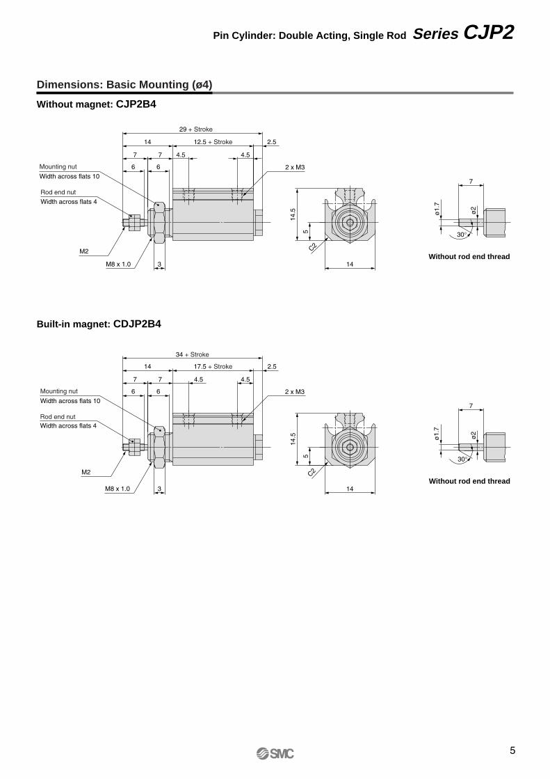
5
Dimensions: Basic Mounting (ø4)
Without magnet: CJP2B4
Built-in magnet: CDJP2B4
14.5
5C2
14
7
30°
ø1.
7
ø2
Without rod end threadM2
Mounting nut
Width across flats 10
Rod end nut
Width across flats 4
29 + Stroke
14 2.5
4.54.577
6
3
6 2 x M3
12.5 + Stroke
M8 x 1.0
14.5
5C2
14
ø1.
7
7
30°
ø2
Without rod end threadM2
Mounting nut
Width across flats 10
Width across flats 4Rod end nut
34 + Stroke
14 2.5
4.54.577
6
3
6 2 x M3
17.5 + Stroke
M8 x 1.0
Pin Cylinder: Double Acting, Single Rod Series CJP2
6
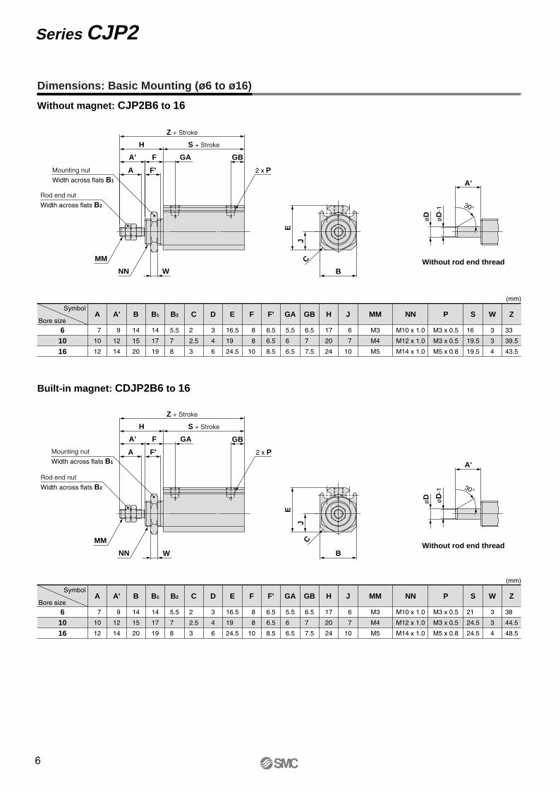
Dimensions: Basic Mounting (ø6 to ø16)
Without magnet: CJP2B6 to 16
Built-in magnet: CDJP2B6 to 16
61016
Symbol
Bore size 7
10
12
A
9
12
14
A'
14
15
20
B
14
17
19
B1
5.5
7
8
B2
2
2.5
3
C
3
4
6
D
16.5
19
24.5
E
8
8
10
F
6.5
6.5
8.5
F'
5.5
6
6.5
GA
6.5
7
7.5
GB
17
20
24
H
6
7
10
J
M3
M4
M5
MM
M10 x 1.0
M12 x 1.0
M14 x 1.0
NN
M3 x 0.5
M3 x 0.5
M5 x 0.8
P
16
19.5
19.5
S
3
3
4
W
33
39.5
43.5
Z
61016
Symbol
Bore size 7
10
12
A
9
12
14
A'
14
15
20
B
14
17
19
B1
5.5
7
8
B2
2
2.5
3
C
3
4
6
D
16.5
19
24.5
E
8
8
10
F
6.5
6.5
8.5
F'
5.5
6
6.5
GA
6.5
7
7.5
GB
17
20
24
H
6
7
10
J
M3
M4
M5
MM
M10 x 1.0
M12 x 1.0
M14 x 1.0
NN
M3 x 0.5
M3 x 0.5
M5 x 0.8
P
21
24.5
24.5
S
3
3
4
W
38
44.5
48.5
Z
Without rod end thread
Without rod end thread
(mm)
(mm)
30°
A'
øD
øD
-1
E
JC
B
MM
Mounting nut
Width across flats B1
Width across flats B2
Rod end nut
Z + Stroke
2 x P
S + Stroke
NN W
A F'
A' F GBGA
H
30°
A'
øD øD
-1
E
JC
B
MM
Mounting nut
Width across flats B1
Width across flats B2
Rod end nut
Z + Stroke
2 x P
S + Stroke
NN W
A F'
A' F GBGA
H
Series CJP2

7
Mounting Bracket Dimensions
Flange: C(D)JP2F6 to 16
Flange
Foot: C(D)JP2L6 to 16
Foot
Clevis: C(D)JP2D6 to 16
Trunnion: C(D)JP2T6 to 16 Rotation angle
Trunnion
61016
Symbol
Bore size3.44.55.5
FC
1.61.62.3
FT
18.521 25.5
FW
242836
FX
161822
FY
323749
FZ
∗ Other dimensions are the same as basic mounting.
61016
Symbol
Bore size 6.57
10
X
10.512 16.5
Y
3.44.55.5
LC
111318
LH
1.61.62.3
LT
21.525 32.5
LW
202430
LX
283343
LZ
∗ Other dimensions are the same as basic mounting.
Clevis
61016
Symbol
Bore size3+0.040
0
5+0.0650
6+0.0650
11.518 22
QGB
4 6.510
CKCD
61016
Symbol
Bore size38 50.558
43 55.563
ZZWithoutmagnet
Built-inmagnet
344448
394953
ZWithoutmagnet
Built-inmagnet
21 30.534
—
26 35.539
SWithoutmagnet
Built-inmagnet
17 0–0.5
22 0–0.5
61016
Symbol
Bore size356
CD
162025
CH
4 6.510
CK
12 13.515
CT
1.61.62.9
CU
182429
CX
3.44.55.5
CY
263342
CZZZZ
38 50.558
Withoutmagnet
43 55.563
Built-inmagnet
Built-inmagnet
394953
Withoutmagnet
344448
T
20.423.931.7
Q
18.520.528
(mm)
(mm)
(mm)
(mm)
∗ Provided as guidelines. The values are varied depending on the condition.
54°110°
≈ A≈ B
Applicable bore ø6 ø10 ø16 62°110°
55°102°
FT
Flange
FX
FZ
2 x FCF
YFW
LT
2 x LC
LX
XY
Foot
LZ
LHL
W
Q
2 x CY
CU
CX
Mounting dimensions oftrunnion bracket
CH
T
Q
Trunnion
Z + Stroke CK
CZ
20°
ZZ + Stroke CT
Pin hole dia. CDC-type retaining ring
ZZ + Stroke
Z + Stroke CK
S + Stroke
GB
CD with flange bushing(None for ø6)
≈ A
≈ B
Pin Cylinder: Double Acting, Single Rod Series CJP2

8
MMA
NC0.5
øD
L
MMA
WN
RR øD
L
Accessory Bracket Dimensions
Single knuckle joint
Knuckle pin
Mounting nut
Rod end nut
Double knuckle joint
Trunnion pin
Rod end capFlat type: CJ-CF
Round type: CJ-CR
Material: Rolled steel
Part no.
I-P006AI-P010AI-P016A
Applicablebore size
(mm)
6
10
16
A
5
6.5
7
B
6
10
12
L1
12
16
19
L2
3.5
5.5
7
MM
M3
M4
M5
NDH10 NX
3
5
6
R1
5
8
10
R2
4
6.3
7.8
U
5
7
9
3
5
6
+0.0400
+0.0480
+0.0480
Material: Rolled steel∗ Knuckle pin and retaining ring are included.
Part no.
Y-P006AY-P010AY-P016A
Applicablebore size
(mm)
6
10
16
A
5
6.5
7
B
6
10
12
L
9
13.6
15.8
L1
12
16
19
L2
3.5
5.5
7
MM
M3
M4
M5
NX
3
5
6
R1
5
8
10
R2
4
6.3
7.8
U
5
7
9
NDd9
3
5
6
–0.020–0.045
–0.030–0.060
–0.030–0.060
NDH10
3
5
6
+0.0400
+0.0480
+0.0480
Material: Brass
Part no. Applicable bore size (mm)
4
6
10
16
dM8 x 1.0
M10 x 1.0
M12 x 1.0
M14 x 1.0
H3
3
3
4
B10
14
17
19
C11.5
16.2
19.6
21.9
Material: Iron
Part no. Applicable bore size (mm)
4
6
10
16
dM2
M3
M4
M5
H1.6
1.8
2.4
3.2
B4
5.5
7
8
C4.6
6.4
8.1
9.2
Flat type
CJ-CF004CJ-CF006CJ-CF010CJ-CF016
Part no.
Round type
CJ-CR004CJ-CR006CJ-CR010CJ-CR016
Applicablebore size
(mm)A D L MM N RR W
5
6
8
10
4
6
10
16
6
8
10
12
9
11
13
15
M2
M3
M4
M5
3
5
6
7
6
8
10
12
5
6
8
10
Material: Polyacetal
NTJ-004NTP-006NTP-010NTP-015
SNPS-004SNP-006SNP-010SNP-015
∗ Included ∗ Included
Material: Stainless steel
Part no.
CT-P006CT-P010CT-P015
6
10
16
D d9
3
5
6
–0.020–0.045
–0.030–0.060
–0.030–0.060
L
20.4
23.9
31.7
d
2.85
4.8
5.7
l
17.6
20.5
28.1
m
0.75
1
1
t
0.65
0.7
0.8
Retainingring
Applicablebore size
(mm)
∗
Material: Stainless steel
Part no.
IY-P006IY-P010IY-P015
Applicablebore size
(mm)
6
10
16
D d9
–0.020–0.0453
5
6
–0.030–0.060
–0.030–0.060
L
9
13.6
15.8
d
2.85
4.8
5.7
l
6.2
10.2
12.2
m
0.75
1
1
t
0.65
0.7
0.8
Retainingring
Clip C-type 3
C-type 5
C-type 6
Clip C-type 3
C-type 5
C-type 6
∗
øND hole H10Axis d9
Series CJP2
9
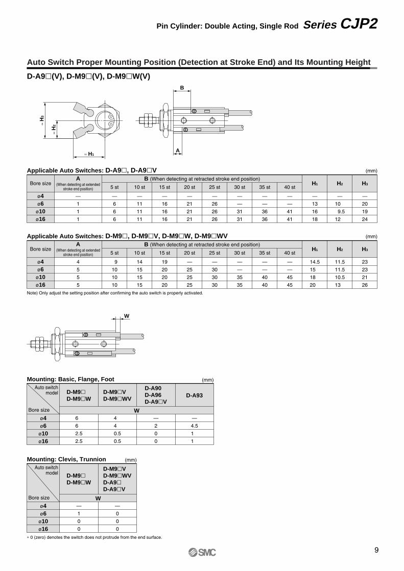
Auto Switch Proper Mounting Position (Detection at Stroke End) and Its Mounting Height
Note) Only adjust the setting position after confirming the auto switch is properly activated.
Bore sizeA
(When detecting at extendedstroke end position) 5 st
Applicable Auto Switches: D-A9, D-A9VB (When detecting at retracted stroke end position)
—
1
1
1
—
6
6
6
ø4ø6
ø10ø16
10 st
—
11
11
11
15 st
—
16
16
16
20 st
—
21
21
21
25 st
—
26
26
26
30 st
—
—
31
31
35 st
—
—
36
36
40 st
(mm)
—
—
41
41
H1
—
13
16
18
H2
—
10
9.5
12
H3
—
20
19
24
Bore sizeA
(When detecting at extendedstroke end position) 5 st
Applicable Auto Switches: D-M9, D-M9V, D-M9W, D-M9WVB (When detecting at retracted stroke end position)
4
5
5
5
9
10
10
10
ø4ø6
ø10ø16
10 st
14
15
15
15
15 st
19
20
20
20
20 st
—
25
25
25
25 st
—
30
30
30
30 st
—
—
35
35
35 st
—
—
40
40
40 st
(mm)
—
—
45
45
H1
14.5
15
18
20
H2
11.5
11.5
10.5
13
H3
23
23
21
26
D-A9(V), D-M9(V), D-M9W(V)
≈ H1
≈ H
3
≈ H
2
A
B
∗ 0 (zero) denotes the switch does not protrude from the end surface.
Mounting: Clevis, Trunnion
D-M9D-M9W
—
1
0
0
—
0
0
0
D-M9VD-M9WVD-A9D-A9V
W
(mm)
Bore size
ø4ø6
ø10ø16
Auto switchmodel
Mounting: Basic, Flange, Foot
D-M9D-M9W
6
6
2.5
2.5
4
4
0.5
0.5
—
2
0
0
—
4.5
1
1
D-M9VD-M9WV
D-A90D-A96D-A9V
D-A93
W
(mm)
Bore size
Auto switchmodel
ø4ø6
ø10ø16
W
Pin Cylinder: Double Acting, Single Rod Series CJP2

10
Operating Range Minimum Stroke for Auto Switch Mounting
Note) The operating range is a guide including hysteresis, but is not guaranteed. There may be large variations (as much ±30%) depending on the ambient environ-ment.
No. of autoswitches mounted D-A9, D-A9V
Applicable auto switch model
5
10
1
2
D-M9, D-M9V5
5
D-M9W, D-M9WV 5
10
1. If cylinders with auto switches are used in parallel, keep the distance between cylinders in accordance with the below
Caution
Use caution not to use them closer than the specified pitch. Ot-herwise, it may cause the auto switches to malfunction.
Before handling auto switches, refer to back page 2 through to 5 for Auto Switches Precautions.
(mm)
Mounting and Moving Auto Switches
Mounting pitch
Watchmaker’s screwdriver
Auto switch
Mounting screw
q Fit an auto switch into the switch mounting groove and set it roughly to the mounting position for an auto switch.
w After reconfirming the detecting position, tighten the mounting screw ∗ to secure the auto switch.
e Modification of the detecting position should be made during step q.∗ When tightening an auto switch mounting screw, use a watchmaker’s screwdriver with a handle of
approximately 5 to 6 mm in diameter.(Use a tightening torque of approximately 0.10 to 0.20 N·m.)
Auto switch modelBore size
4
—
25
D-A9(V)D-M9(V)D-M9W(V)
6
20
25
25
30
30
35
10 16
Mounting Pitch (mm)
Auto switch modelBore size
4
—
2
2.5
D-A9(V)D-M9(V)D-M9W(V)
6
5
2
2.5
10
6
2
3
16
7
2
3.5
(mm)
∗
Specific Product Precautions
Series CJP2
11
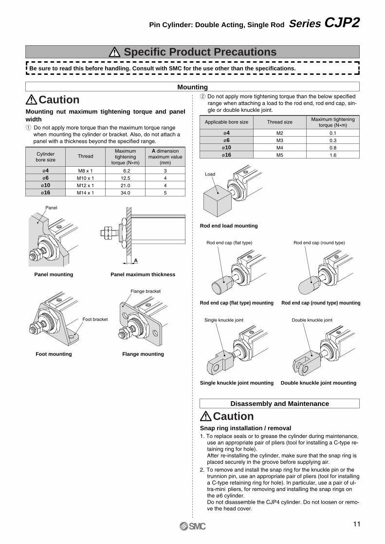
Be sure to read this before handling. Consult with SMC for the use other than the specifications.
Mounting
Mounting nut maximum tightening torque and panel widthq Do not apply more torque than the maximum torque range
when mounting the cylinder or bracket. Also, do not attach a panel with a thickness beyond the specified range.
Caution
Cylinderbore size
ø4ø6
ø10ø16
M8 x 1
M10 x 1
M12 x 1
M14 x 1
6.2
12.5
21.0
34.0
ThreadMaximumtightening
torque (N m)
3
4
4
5
A dimensionmaximum value
(mm)
w Do not apply more tightening torque than the below specified range when attaching a load to the rod end, rod end cap, sin-gle or double knuckle joint.
A
Panel mounting
Rod end cap (flat type) mounting Rod end cap (round type) mounting
Single knuckle joint mounting Double knuckle joint mounting
Rod end load mounting
Panel maximum thickness
Foot mounting Flange mounting
Panel
Foot bracket
Flange bracket
Applicable bore size
ø4ø6
ø10ø16
M2
M3
M4
M5
0.1
0.3
0.8
1.6
Thread size Maximum tighteningtorque (N m)
Double knuckle jointSingle knuckle joint
Load
Rod end cap (flat type)
Disassembly and Maintenance
Snap ring installation / removal1. To replace seals or to grease the cylinder during maintenance,
use an appropriate pair of pliers (tool for installing a C-type re-taining ring for hole).After re-installing the cylinder, make sure that the snap ring is placed securely in the groove before supplying air.
2. To remove and install the snap ring for the knuckle pin or the trunnion pin, use an appropriate pair of pliers (tool for installing a C-type retaining ring for hole). In particular, use a pair of ul-tra-mini pliers, for removing and installing the snap rings on the ø6 cylinder.Do not disassemble the CJP4 cylinder. Do not loosen or remo-ve the head cover.
Caution
Rod end cap (round type)
Specific Product Precautions
Pin Cylinder: Double Acting, Single Rod Series CJP2

12
Pin Cylinder: Single Acting, Spring Return
ø4, ø6, ø10, ø15Series CJP
Embedded type
Panel mount type
ø4, ø6, ø10, ø15
B 15CJP
Cylinder standard stroke (mm)
Rod end threadBS
Panel mount typeEmbedded type
5, 10, 15
(Hose nipple is not attached to embedded style.)
-H4H6
With threadWithout thread
-B
∗ Refer to caution on piping on page 16.Embedded type Panel mount type
XC17
XC22
Pin cylinder with rod quenched
Fluoro rubber seals
Symbol Specifications
Mounting
Application Examples
Specifications
How to Order
JIS Symbol Single acting, Spring return
A short stroke miniature cylinder with a shorter overall length.The installation space can be significantly reduced because this cylinder can be re-cessed directly into a machine body or ins-talled on a panel. Thus, the machine can be made more compact.
Pin cylinder
Clamper Ejector Gripper Stopper
Mounting
Bore size
Without hose nipple ∗
For ø4/ø2.5 tubingFor ø6/ø4 tubing
Hose nipple(Applicable to the mountingtype B panel mount type (ø6 to ø15) only.)
10 H4
Action
Maximum operating pressure
ø4
ø6
ø10, ø15
Accessory(Standard equipment)
Standard equipment
Option
Single acting, Spring return
0.7 MPa
0.3 MPa
0.2 MPa
0.15 MPa
1.05 MPa
–10 to 70°C (No freezing)
Not required (Non-lube)
50 to 500 mm/s
None
JIS Class 2
With thread/Without thread
+1.0 0
Panel mount type
Hose nipple (Except ø4) —
Embedded type
Mounting nut (1)Gasket (1)
Rod end nut (2)
∗ When rod end is threaded.
Mounting nut (2)Rod end nut (2)
461015
4 mm6 mm
10 mm15 mm
Made to Order Refer to the table below.
Made to Order(For details, refer to page 22, 23.)
Minimum operating pressure
Proof pressure
Ambient and fluid temperature
Lubrication
Piston speed
Cushion
Stroke length tolerance
Thread tolerance
Rod end style
Mounting
∗ ∗

13
(N)
Bore size(mm)
4
6
10
15
Operatingdirection
OUT
IN
OUT
IN
OUT
IN
OUT
IN
Operating pressure (MPa)
0.3
0.97
4.56
17.6
42.2
0.5
1.0
1.42
2.45
4.41
3.48
10.2
33.3
77.5
0.7
6.00
15.9
49.0
113
∗ Weight of hose nipple (4 g) for panel mounting is excluded.
Bore size (mm)
4
6
10
15
Stroke (mm)
5, 10, 15
5, 10, 15
5, 10, 15
5, 10, 15
Bore size(mm)
Stroke(mm)
Retractedside
Extendedside
5, 10, 15
5, 10, 15
5, 10, 15
5, 10, 15
2.80
3.92
5.98
10.80
1.00
1.42
2.45
4.41
4
6
10
15
(N)
∗ Same spring force for each stroke.
(g)
Model5
10
10.6
28
72
10
13
13.1
33
82
Stroke (mm)
15
15
15.6
38
92
CJP4
CJP6
CJP10
CJP15
Standard Stroke
Spring Reaction Force
Applicable tubing
For ø4/ø2.5 tubing
For ø6/ø4 tubing
Part no.
CJ-5H-4
CJ-5H-6
Hose Nipple Dedicated for Panel Mount Type(With fixed orifice)
Weight Theoretical Output
Construction (Not possible to disassemble.)
Panel mount type Embedded type
Mounting nut
Rod end nut
Dedicated Nut / Part No.Bore size
(mm)Description
Mounting nut
Rod end nut
SNPS-006
NTP-006
SNPS-010
NTP-010
SNPS-015
NTP-015
6
SNPS-004
NTJ-004
4 10 15
i e u q r w t y
Material: Brass
Part no.
SNPS-004SNPS-006SNPS-010SNPS-015
Applicablebore size mm)
4
6
10
15
d
M8 x 1.0
M10 x 1.0
M15 x 1.5
M22 x 1.5
H
3
3
4
5
B
10
12
19
27
C
11.5
13.9
22
31
Material: Steel
Part no.
NTJ-004NTP-006NTP-010NTP-015
Applicablebore size mm)
4
6
10
15
d
M2
M3
M4
M5
H
1.6
1.8
2.4
3.2
B
4
5.5
7
8
C
4.6
6.4
8.1
9.2
No. Description
Cover
Piston
Collar
Return spring
Piston seal
Gasket
Mounting nut
Rod end nut
Material Note
ø4
ø6, ø10
Brass + Electroless nickel plated
Bronze
Component Parts
1
2
3
4
5
6
7
8
Brass
Stainless steel
Oil-impregnated sintered alloy
Steel wire
NBR
NBR
Brass
Steel
Electroless nickel plated
Zinc chromated
Special product (O-ring) embedded type only
Electroless nickel plated
Nickel plated
∗ Dedicated for the embedded type.
CJPS4-G
CJPS6-G
CJPS10-G
CJPS15-G
461015
Replacement Parts / GasketBore size (mm) Order no. Contents
Above no. y
Pin Cylinder: Single Acting, Spring Return Series CJP
14
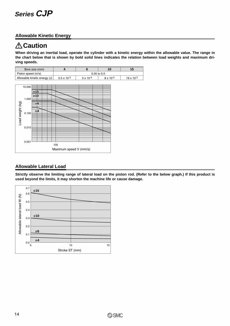
When driving an inertial load, operate the cylinder with a kinetic energy within the allowable value. The range in the chart below that is shown by bold solid lines indicates the relation between load weights and maximum dri-ving speeds.
Caution
Allowable Kinetic Energy
Strictly observe the limiting range of lateral load on the piston rod. (Refer to the below graph.) If this product is used beyond the limits, it may shorten the machine life or cause damage.
Allowable Lateral Load
4
0.5 x 10⁻³
6
3 x 10⁻³
10
8 x 10⁻³
15
19 x 10-3
Bore size (mm)
0.05 to 0.5Piston speed (m/s)
Allowable kinetic energy (J)
0.001100
Maximum speed V (mm/s)
0.010
0.100
1.000
10.000
Load
wei
ght (
kg)
ø4
ø15ø10
ø6
Stroke ST (mm)
Allo
wab
le la
tera
l loa
d W
(N
)
0.0
0.1
0.2
0.3
0.4
0.5
0.6
0.7
10 155
ø4
ø6
ø15
ø10
Series CJP
15
Air
G
Air
E A
C
øF
H8
B D0–0.5 O-ring seal
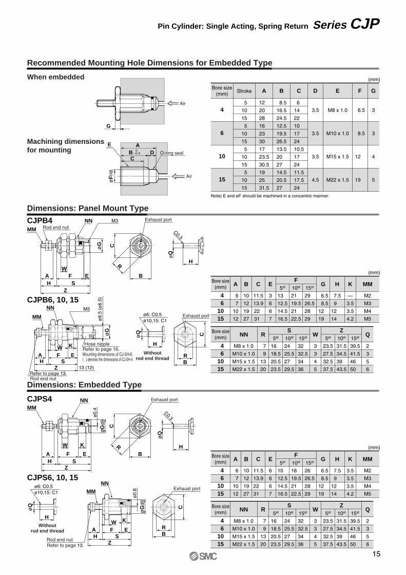
Recommended Mounting Hole Dimensions for Embedded Type
When embedded
Machining dimensions for mounting
Dimensions: Panel Mount TypeCJPB4
Dimensions: Embedded Type
CJPS4
CJPB6, 10, 15
CJPS6, 10, 15
Bore size(mm) Stroke
5
10
15
5
10
15
5
10
15
5
10
15
A
12
20
28
16
23
30
17
23.5
30.5
19
25
31.5
B
8.5
16.5
24.5
12.5
19.5
26.5
13.5
20
27
14.5
20.5
27
C
6
14
22
10
17
24
10.5
17
24
11.5
17.5
24
D
3.5
3.5
3.5
4.5
E
M8 x 1.0
M10 x 1.0
M15 x 1.5
M22 x 1.5
F
6.5
8.5
12
19
G
3
3
4
5
4
6
10
15
Note) E and øF should be machined in a concentric manner.
M2
M3
M4
M5
MM
13
12.5
14.5
16.5
5st
Bore size(mm)
4 61015
A
6
7
10
12
10
12
19
27
11.5
13.9
22
31
3
6
6
7
6.5
8.5
12
19
7.5
9
12
14
—
3.5
3.5
4.2
B C E G H KF
M8 x 1.0
M10 x 1.0
M15 x 1.5
M22 x 1.5
7
9
13
20
16
18.5
20.5
23.5
24
25.5
27
29.5
32
32.5
34
36
3
3
4
5
23.5
27.5
32.5
37.5
31.5
34.5
39
43.5
39.5
41.5
46
50
2
3
5
6
NN R5st 10st
S15st W Q
5st 10st
Z15st
21
19.5
21
22.5
10st
29
26.5
28
29
15st
M2
M3
M4
M5
MM
10
12.5
14.5
16.5
5st
Bore size(mm)
4 61015
A
6
7
10
12
10
12
19
27
11.5
13.9
22
31
6
6
6
7
6.5
8.5
12
19
7.5
9
12
14
3.5
3.5
3.5
4.2
B C E G H KF
M8 x 1.0
M10 x 1.0
M15 x 1.5
M22 x 1.5
7
9
13
20
16
18.5
20.5
23.5
24
25.5
27
29.5
32
32.5
34
36
3
3
4
5
23.5
27.5
32.5
37.5
31.5
34.5
39
43.5
39.5
41.5
46
50
2
3
5
6
NN R5st 10st
S15st W Q
5st 10st
Z15st
18
19.5
21
22.5
10st
26
26.5
28
29
15st
Bore size(mm)
4 61015
Bore size(mm)
4 61015
C
R
B
Exhaust port
Rod end nutMM
NN M3
øG
HZ
SA F
øQ
H
H
øQ
C0.3
Exhaust port
C
B
R
C0.3
EW
NNMM
EFAH S
Z
KW
øGd9
NN
MM
Rod end nutRefer to page 13.
øG
d9
ø0.
8
AWF E
SZ
H
K
NN
MM
Rod end nutRefer to page 13.
M5
øG
ø8.
5 (ø
6.5)
Hose nippleRefer to page 16.Mounting dimensions of CJ-5H-6.( ) denotes the dimensions of CJ-5H-4.
13 (12)
AWF E
SZ
H
K H
øQ
ø6: C0.5ø10,15: C1
Withoutrod end thread
Exhaust port
C
RB
H
øQ
ø6: C0.5ø10,15: C1
Withoutrod end thread
Exhaust port
C
RB
ø0.
4
(mm)
(mm)
(mm)
Pin Cylinder: Single Acting, Spring Return Series CJP
16
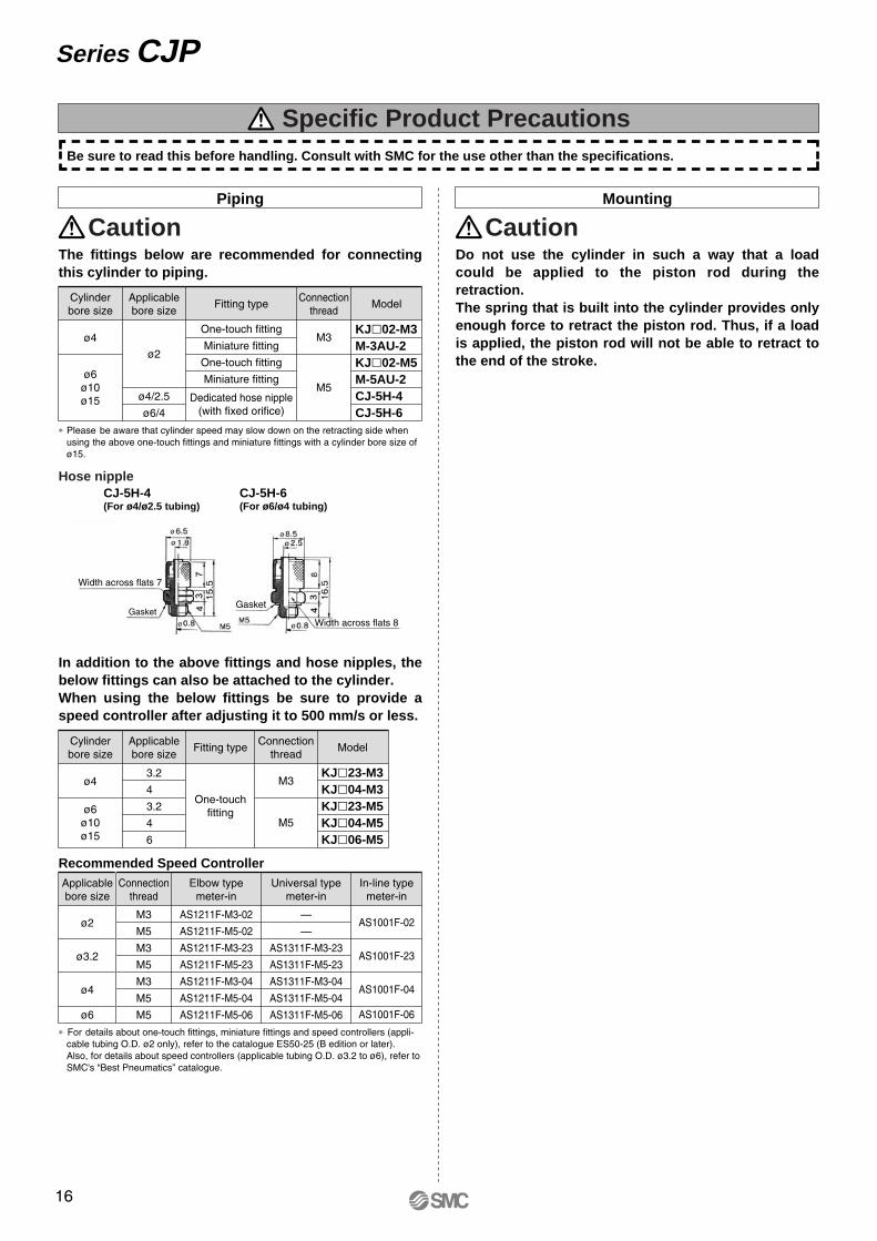
Be sure to read this before handling. Consult with SMC for the use other than the specifications.
Piping
The fittings below are recommended for connecting this cylinder to piping.
∗ Please be aware that cylinder speed may slow down on the retracting side when using the above one-touch fittings and miniature fittings with a cylinder bore size of ø15.
Caution
Cylinderbore size
ø4
ø6ø10ø15
ø2
ø4/2.5
ø6/4
One-touch fitting
Miniature fitting
One-touch fitting
Miniature fitting
M3
M5
KJ02-M3M-3AU-2KJ02-M5M-5AU-2CJ-5H-4CJ-5H-6
Dedicated hose nipple(with fixed orifice)
Applicablebore size
Fitting typeConnection
threadModel
∗ For details about one-touch fittings, miniature fittings and speed controllers (appli-cable tubing O.D. ø2 only), refer to the catalogue ES50-25 (B edition or later).Also, for details about speed controllers (applicable tubing O.D. ø3.2 to ø6), refer to SMC's “Best Pneumatics” catalogue.
AS1001F-02
AS1001F-23
AS1001F-04
AS1001F-06
Applicablebore size
ø2
ø3.2
ø4
ø6
M3
M5
M3
M5
M3
M5
M5
AS1211F-M3-02
AS1211F-M5-02
AS1211F-M3-23
AS1211F-M5-23
AS1211F-M3-04
AS1211F-M5-04
AS1211F-M5-06
—
—
AS1311F-M3-23
AS1311F-M5-23
AS1311F-M3-04
AS1311F-M5-04
AS1311F-M5-06
Connectionthread
Elbow typemeter-in
Universal typemeter-in
In-line typemeter-in
In addition to the above fittings and hose nipples, the below fittings can also be attached to the cylinder.When using the below fittings be sure to provide a speed controller after adjusting it to 500 mm/s or less.
Cylinderbore size
ø4
ø6ø10ø15
M3
M5
One-touchfitting
Applicablebore size
Fitting typeConnection
threadModel
3.2
4
3.2
4
6
KJ23-M3KJ04-M3KJ23-M5KJ04-M5KJ06-M5
Recommended Speed Controller
Hose nippleCJ-5H-4(For ø4/ø2.5 tubing)
CJ-5H-6(For ø6/ø4 tubing)
Mounting
Do not use the cylinder in such a way that a load could be applied to the piston rod during the retraction.The spring that is built into the cylinder provides only enough force to retract the piston rod. Thus, if a load is applied, the piston rod will not be able to retract to the end of the stroke.
Caution
Gasket
Width across flats 7
Width across flats 8
Gasket
Specific Product Precautions
Series CJP
17
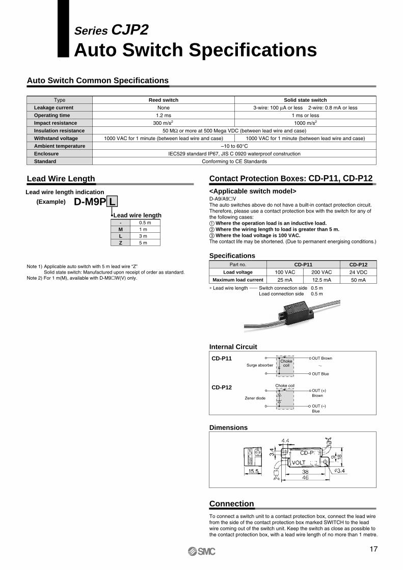
Series CJP2Auto Switch Specifications
Auto Switch Common Specifications
Type
Leakage current
Operating time
Impact resistance
Insulation resistance
Withstand voltage
Ambient temperature
Enclosure
Standard
Reed switch
None
1.2 ms
300 m/s2
50 MΩ or more at 500 Mega VDC (between lead wire and case)
–10 to 60°CIEC529 standard IP67, JIS C 0920 waterproof construction
Conforming to CE Standards
Solid state switch
3-wire: 100 µA or less 2-wire: 0.8 mA or less
1 ms or less
1000 m/s2
1000 VAC for 1 minute (between lead wire and case) 1000 VAC for 1 minute (between lead wire and case)
Lead Wire Length
Lead wire length indication
(Example)
LM
0.5 m
3 m1 m
5 mZ
-
Lead wire length
LD-M9P
Contact Protection Boxes: CD-P11, CD-P12
D-A9/A9VThe auto switches above do not have a built-in contact protection circuit.Therefore, please use a contact protection box with the switch for any of the following cases: Where the operation load is an inductive load. Where the wiring length to load is greater than 5 m. Where the load voltage is 100 VAC.The contact life may be shortened. (Due to permanent energising conditions.)
Specifications
Internal Circuit
Dimensions
Connection
∗ Lead wire length Switch connection side 0.5 mLoad connection side 0.5 m
Part no.
Load voltage
Maximum load current
CD-P11
CD-P11
100 VAC
25 mA
200 VAC
12.5 mA
CD-P12
24 VDC
50 mA
To connect a switch unit to a contact protection box, connect the lead wire from the side of the contact protection box marked SWITCH to the leadwire coming out of the switch unit. Keep the switch as close as possible to the contact protection box, with a lead wire length of no more than 1 metre.
CD-P12
Surge absorberChoke
coil
OUT Brown
OUT Blue
OUT (+)Brown
OUT (–)Blue
Choke coil
Zener diode
Note 1) Applicable auto switch with 5 m lead wire “Z” Solid state switch: Manufactured upon receipt of order as standard.
Note 2) For 1 m(M), available with D-M9W(V) only.
<Applicable switch model>
18
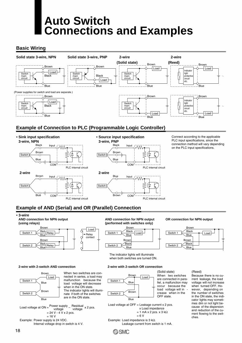
Auto SwitchConnections and Examples
Basic Wiring
Solid state 3-wire, NPN 2-wireSolid state 3-wire, PNP(Solid state)
2-wire(Reed)
• Sink input specification3-wire, NPN
• 3-wire
• Source input specification3-wire, PNP
OR connection for NPN output
2-wire with 2-switch AND connection 2-wire with 2-switch OR connection
2-wire 2-wire
Switch
InputBlack
COM
Brown
Blue
Switch
Input
Blue COM
Brown
Switch
InputBlack
PLC internal circuitCOM
Brown
Blue
PLC internal circuit
PLC internal circuit
PLC internal circuit
Switch
InputBlue
COMBrown
Connect according to the applicable PLC input specifications, since the connection method will vary depending on the PLC input specifications.
(Power supplies for switch and load are separate.)
Example of AND (Serial) and OR (Parallel) Connection
Example of Connection to PLC (Programmable Logic Controller)
AND connection for NPN output(using relays)
AND connection for NPN output(performed with switches only)
The indicator lights will illuminate when both switches are turned ON.
Switch main circuit
Brown
Black
Blue
Load
Brown
Black
Blue
Load
Brown
Black
Blue
Load
Brown
Blue
Load
Brown
BlueLoad
Indicator light protectivecircuitetc.
Brown
Blue
Load
Brown
BlueLoad
Switch main circuit
Switch main circuit
Switch main circuit
Switch main circuit
Indicator light protectivecircuitetc.
Switch 1
Switch 2
Load
BrownBlackBlue
BrownBlackBlue
Switch 1
Brown
Switch 2
BlackBlue
Relay
Relay
BrownBlackBlue
Load
Relay contact
Switch 1
Brown
Switch 2
BlackBlue
Load
BrownBlackBlue
Power supply ResidualLoad voltage at ON = voltage – voltage x 2 pcs.
= 24 V - 4 V x 2 pcs.= 16 V
Example: Power supply is 24 VDC. Internal voltage drop in switch is 4 V.
Load voltage at OFF = Leakage current x 2 pcs. x Load impedance= 1 mA x 2 pcs. x 3 kΩ= 6 V
Example: Load impedance is 3 kΩ.Leakage current from switch is 1 mA.
Switch 1
Switch 2
Brown
Blue
Brown
Blue
LoadSwitch 1
Switch 2
Brown
Blue
Brown
Blue
Load
(Solid state) (Reed)When two switches are con-nected in series, a load may malfunction because the load voltage will decrease when in the ON state.The indicator lights will illumi-nate if both of the switches are in the ON state.
When two switches are connected in para-llel, a malfunction may occur because the load voltage will in -crease when in the OFF state.
Because there is no cu-rrent leakage, the load voltage will not increase when turned OFF. Ho-wever, depending on the number of switches in the ON state, the indi-cator lights may someti-mes dim or not light be-cause of the dispersion and reduction of the cu-rrent flowing to the swit-ches.

19
( ): dimensions for D-A93.D-A90V/D-A93V/D-A96V
Auto Switch Specifications
Reed Switch: Direct Mounting StyleD-A90(V)/D-A93(V)/D-A96(V)
Grommet PLC: Programmable Logic Controller
Note) q In a case where the operation load is an inductive load.
w In a case where the wiring load is greater than 5 m.
e In a case where the load voltage is 100 VAC.
Use the auto switch with a contact protection box in any of the above mentioned cases. (For details about the contact protection box, refer to page 17.)
Fix the switch with the existing screw installed on the switch body. The switch may be damaged if a screw other than the one supplied, is used.
Operating PrecautionsCaution
Auto switch part no.
Lead wire length 0.5 m
Lead wire length 3 m
D-A90(V) 6
30
D-A93(V) 6
30
D-A96(V) 8
41
Unit: g
Unit: mm
Weight
Auto Switch Internal Circuit
D-A90(V)
D-A93(V)
D-A96(V)
DimensionsD-A90/D-A93/D-A96
Lead wiresD-A90(V)/D-A93(V) — Oilproof heavy-duty vinyl cable: ø2.7, 0.18 mm2 x 2 cores (Brown, Blue), 0.5 mD-A96(V) — Oilproof heavy-duty vinyl cable: ø2.7, 0.15 mm2 x 3 cores (Brown, Black, Blue), 0.5 m
Note 1) Refer to page 17 for reed switch common specifications.Note 2) Refer to page 17 for lead wire lengths.
IC circuit, Relay, PLC
24 VAC/DC or less
50 mA
None
1 Ω or less (including lead wire length of 3 m)
48 VAC/DC or less
40 mA
100 VAC/DC or less
20 mA
Relay, PLC
24 VDC
5 to 40 mA
None
D-A93 — 2.4 V or less (to 20 mA)/3 V or less (to 40 mA)D-A93V — 2.7 V or less
Red LED illuminates when ON.
Conforming to CE Standards
100 VAC
5 to 20 mA
IC circuit
4 to 8 VDC
20 mA
0.8 V or less
Auto switch part no.
Electrical entry direction
Applicable load
Load voltage
Maximum load current
Contact protection circuit
Internal resistance
D-A93/D-A93V/D-A96/D-A96V (With indicator light)Auto switch part no.
Electrical entry direction
Applicable load
Load voltage
Indicator light
Standard
Contact protection circuit
Load current rangeand max. load current
Internal voltage drop
D-A90VD-A90 D-A90 D-A90VD-A90VD-A90In-line Perpendicular In-line Perpendicular In-line Perpendicular
D-A93VD-A93 D-A96 D-A96VD-A93VD-A93In-line Perpendicular In-line Perpendicular In-line Perpendicular
D-A90/D-A90V (Without indicator light)
ø2.
7
2 2.8
4.5422
(24.5)
10
Indicator lightD-A90 type comes without indicator light.
Most sensitive position
M2.5 x 4 lSlotted set screw
2
22
6
Indicator lightD-A90V type comes without indicator light.
M2.5 x 4 lSlotted set screw
ø2.7
10 Most sensitive position
4.5
49.1
5.1
For details about certified products conforming tointernational standards, visit us at www.smcworld.com.
Ree
d sw
itch
Ree
d sw
itch
Ree
d sw
itch
LED diode
LED diode
Contact protection box
CD-P11
CD-P12
OUT (±)Brown
OUT (±)Blue
OUT (+)Brown
OUT (–)Blue
Contact protection box
CD-P11
CD-P12
Blue
Resistor
Zener diode
Brown
LED diode
Resistor
Reverse current prevention diode
OUTBlack
DC (+)Brown
DC (–)Blue
Load
(+)
(–)
DC powersupply
20
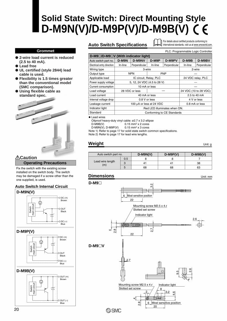
Solid State Switch: Direct Mounting StyleD-M9N(V)/D-M9P(V)/D-M9B(V)
Auto Switch Internal CircuitD-M9N(V)
D-M9B(V)
D-M9P(V)
Auto Switch Specifications
Weight
Auto switch part no.
0.5
3
5
D-M9N(V) 8
41
68
D-M9P(V) 8
41
68
D-M9B(V) 7
38
63
Unit: g
Lead wire length(m)
Grommet PLC: Programmable Logic Controller
Auto switch part no.
Electrical entry direction
Wiring type
Output type
Applicable load
Power supply voltage
Current consumption
Load voltage
Load current
Internal voltage drop
Leakage current
Indicator light
Standard
D-M9NVD-M9N D-M9B D-M9BV
2-wire
—
24 VDC relay, PLC
—
—
24 VDC (10 to 28 VDC)
2.5 to 40 mA
4 V or less
0.8 mA or less
D-M9PVD-M9P
Red LED illuminates when ON.
Conforming to CE Standards
3-wire
IC circuit, Relay, PLC
5, 12, 24 VDC (4.5 to 28 V)
10 mA or less
40 mA or less
0.8 V or less
100 µA or less at 24 VDC
In-line Perpendicular In-line Perpendicular In-line Perpendicular
NPN PNP
28 VDC or less —
D-M9/D-M9V (With indicator light)
Lead wiresOilproof heavy-duty vinyl cable: ø2.7 x 3.2 ellipse D-M9B(V) 0.15 mm2 x 2 coresD-M9N(V), D-M9P(V) 0.15 mm2 x 3 cores
Note 1) Refer to page 17 for solid state switch common specifications.Note 2) Refer to page 17 for lead wire lengths.
Dimensions
D-M9
D-M9V
Mounting screw M2.5 x 4 lSlotted set screw
Indicator light
2.7
22
22
2.6
4
2.8
3.2
6 Most sensitive position
4
2.6
9.5
2.7
4.62
20
Mounting screw M2.5 x 4 l
2.8
83.2
4
6
Indicator lightSlotted set screw
Most sensitive position
2-wire load current is reduced (2.5 to 40 mA).
Lead free UL certified (style 2844) lead
cable is used. Flexibility is 1.5 times greater
than the conventional model (SMC comparison).
Using flexible cable as standard spec.
Operating PrecautionsCaution
Fix the switch with the existing screw installed on the switch body. The switch may be damaged if a screw other than the one supplied, is used.
Unit: mm
For details about certified products conforming tointernational standards, visit us at www.smcworld.com.
Sw
itch
mai
n ci
rcui
tS
witc
h m
ain
circ
uit
Sw
itch
mai
n ci
rcui
t
OUTBlack
DC (+)Brown
DC (–)Blue
OUTBlack
DC (+)Brown
DC (–)Blue
OUT (+)Brown
OUT (–)Blue

21
Auto Switch Specifications
Weight Unit: g
Unit: mmDimensions
Auto switch part no.
0.5
1
3
5
D-M9NW(V)8
14
41
68
D-M9PW(V)8
14
41
68
D-M9BW(V)7
13
38
63
Lead wire length(m)
Grommet PLC: Programmable Logic Controller
Auto switch part no.
Electrical entry direction
Wiring type
Output type
Applicable load
Power supply voltage
Current consumption
Load voltage
Load current
Internal voltage drop
Leakage current
Internal voltage drop
Standard
D-M9NWVD-M9NW D-M9BW D-M9BWV
2-wire
—
24 VDC relay, PLC
—
—
24 VDC (10 to 28 VDC)
2.5 to 40 mA
4 V or less
0.8 mA or less
D-M9PWVD-M9PW
Operating position .......... Red LED illuminates.Optimum operating position .......... Green LED illuminates.
3-wire
IC circuit, Relay IC, PLC
5, 12, 24 VDC (4.5 to 28 VDC)
10 mA or less
40 mA or less
0.8 V or less at 10 mA (2 V or less at 40 mA)
100 µA or less at 24 VDC
Conforming to CE Standards
In-line Perpendicular In-line Perpendicular In-line Perpendicular
NPN PNP
28 VDC or less —
D-M9W/D-M9WV (With indicator light)
Lead wiresOilproof heavy-duty vinyl cable: ø2.7 x 3.2 ellipse D-M9BW(V) 0.15 mm2 x 2 coresD-M9NW(V), D-M9PW(V) 0.15 mm2 x 3 cores
Note 1) Refer to page 17 for solid state switch common specifications.Note 2) Refer to page 17 for lead wire lengths.
2-wire load current is reduced (2.5 to 40 mA).
RoHS compliant UL certified (style 2844) lead cable is
used. Flexibility is 1.5 times greater than the
conventional model (SMC comparison). Using flexible cable as standard spec. The optimum operating position can be
determined by the colour of the light. (Red → Green → Red)
D-M9NW(V)
D-M9BW(V)
D-M9PW(V)
Indicator light / Display method
Auto Switch Internal Circuit
ON
OFF
D-M9W
D-M9WV
Mounting screw M2.5 x 4 lSlotted set screw
Indicator light
2.7
22
22
2.6
4
2.8
3.2
6 Most sensitive position
4
2.6
9.5
Mounting screw M2.5 x 4 lIndicator light
Slotted set screw
2.8
4.6
4
620
28
3.2
Most sensitive position
2.7
2-Colour Indication Solid State Switch: Direct Mounting StyleD-M9NW(V)/D-M9PW(V)/D-M9BW(V)
For details about certified products conforming tointernational standards, visit us at www.smcworld.com.
OUTBlack
DC (+)Brown
DC (–)Blue
DC (+)Brown
OUTBlack
DC (–)Blue
OUT (+)Brown
OUT (–)Blue
Sw
itch
mai
n ci
rcui
tS
witc
hm
ain
circ
uit
Sw
itch
mai
n ci
rcui
t
Operatingrange
DisplayRed Green Red
Optimum operatingposition

22
We apply the Simple Made to Order system to the below specials. Contact your SMC representative for details. Simple Specials
Symbol DescriptionDouble acting,
Single rodCJP2
Single acting,Single rod
CJP
Bore size
1 XA0, 1, 10, 11 Change of rod end shape
Made to Order
1 XB6 Heat resistant cylinder (150°C)
2 XB7 Cold resistant cylinder
3 XC17 Pin cylinder with rod quenched
4 XC22 Fluoro rubber seals
ø6 to ø16 ø6 to ø15
ø6 to ø16 —
ø6 to ø16 —
— ø6 to ø15
ø6 to ø16 ø6 to ø15
Change of rod end shape
XA0, XA1, XA10, XA111Simple Specials
H
TPR sphere
H
R sphere
Symbol: A0 Symbol: A1
Symbol: A10
A
H
Symbol: A11
H
30°
∗
Series CJP2/CJPSimple Specials: Made to OrderPlease contact SMC for detailed specifications, lead times, and prices.
CJP2 CJP
Note)
Note)
Note) Except clevis, trunnion type, with switch.
If a rod-end configuration different from standard is required.
1) SMC will make appropriate arrangements if no dimensions, tolerances, or finish instructions are given in the diagram.2) Standard dimensions marked with “∗” will be as follows a relation to the rod diameter (D). D < 6 → D-1 mm 6 < D < 25→ D-2 mm D > 25 → D-4 mm3) In the case of double rod and single acting spring return type, fill in the dimension for when the rod is retracted.
= =
23
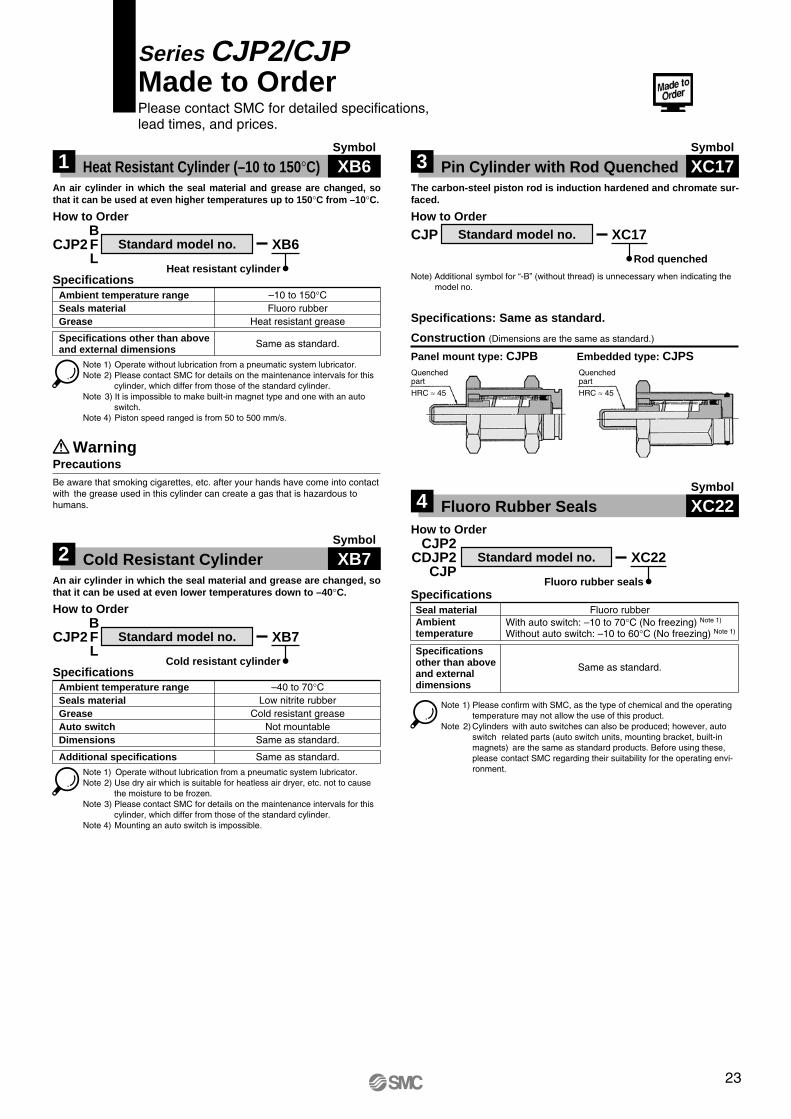
Heat Resistant Cylinder (–10 to 150°C)1 XB6Symbol
An air cylinder in which the seal material and grease are changed, so that it can be used at even higher temperatures up to 150°C from –10°C.
Note 1) Operate without lubrication from a pneumatic system lubricator.Note 2) Please contact SMC for details on the maintenance intervals for this
cylinder, which differ from those of the standard cylinder.Note 3) It is impossible to make built-in magnet type and one with an auto
switch.Note 4) Piston speed ranged is from 50 to 500 mm/s.
XB6CJP2
Heat resistant cylinder
Standard model no.
How to Order
SpecificationsAmbient temperature rangeSeals materialGrease
–10 to 150°CFluoro rubber
Heat resistant grease
Specifications other than above and external dimensions Same as standard.
PrecautionsWarning
Be aware that smoking cigarettes, etc. after your hands have come into contact with the grease used in this cylinder can create a gas that is hazardous to humans.
Cold Resistant Cylinder2 XB7Symbol
An air cylinder in which the seal material and grease are changed, so that it can be used at even lower temperatures down to –40°C.
Note 1) Operate without lubrication from a pneumatic system lubricator.Note 2) Use dry air which is suitable for heatless air dryer, etc. not to cause
the moisture to be frozen.Note 3) Please contact SMC for details on the maintenance intervals for this
cylinder, which differ from those of the standard cylinder.Note 4) Mounting an auto switch is impossible.
XB7CJP2
Cold resistant cylinder
Standard model no.
How to Order
SpecificationsAmbient temperature rangeSeals materialGreaseAuto switchDimensions
–40 to 70°CLow nitrite rubber
Cold resistant greaseNot mountable
Same as standard.
Additional specifications Same as standard.
Pin Cylinder with Rod Quenched3 XC17Symbol
The carbon-steel piston rod is induction hardened and chromate sur-faced.
BFL
BFL
Series CJP2/CJPMade to OrderPlease contact SMC for detailed specifications,lead times, and prices.
Note) Additional symbol for “-B” (without thread) is unnecessary when indicating the model no.
Fluoro Rubber Seals4 XC22Symbol
Note 1) Please confirm with SMC, as the type of chemical and the operating temperature may not allow the use of this product.
Note 2) Cylinders with auto switches can also be produced; however, auto switch related parts (auto switch units, mounting bracket, built-in magnets) are the same as standard products. Before using these, please contact SMC regarding their suitability for the operating envi-ronment.
XC22CJP2
CDJP2CJP
Fluoro rubber seals
Standard model no.
How to Order
SpecificationsSeal materialAmbienttemperature
Fluoro rubberWith auto switch: –10 to 70°C (No freezing) Note 1)
Without auto switch: –10 to 60°C (No freezing) Note 1)
Specifications other than above and external dimensions
Same as standard.
XC17CJP
Rod quenched
Standard model no.How to Order
Specifications: Same as standard.
Panel mount type: CJPB Embedded type: CJPS
Construction (Dimensions are the same as standard.)
Quenchedpart
HRC ≈ 45
Quenchedpart
HRC ≈ 45

Series CJP2/CJP
Safety Instructions
1. The compatibility of the pneumatic equipment is the responsibility of the person who designs the pneumatic system or decides its specifications.Since the products specified here are used in various operating conditions, their compatibility for the specific pneumatic syst em must be based on specifications or post analysis and/or tests to meet the specific requirements. The expected performance and safety assurance are the responsibility of the person who has determined the compatibility of the system. This person should continuously review the suitability of all items specified, referring to the latest catalogue information with a view to giving due consideration to any possibility of equipment failure when configuring a system.
2. Only trained personnel should operate pneumatically operated machinery and equipment.Compressed air can be dangerous if handled incorrectly. Assembly, handling or repair of pneumatic systems should be performed by trained and experienced operators. (Understanding JIS B 8370 General Rules for Pneumatic Equipment, and other safety rules are included.)
3. Do not service machinery/equipment or attempt to remove components until safety is confirmed.1. Inspection and maintenance of machinery/equipment should only be performed once measures to prevent falling or runaway
of the driver objects have been confirmed. 2. When equipment is removed, confirm that safety process as mentioned above. Turn off the supply pressure for this equipment
and exhaust all residual compressed air in the system, and release all the energy (liquid pressure, spring, condenser, gravity).3. Before machinery/equipment is restarted, take measures to prevent quick extension of a cylinder piston rod, etc.
4. Contact SMC if the product will be used in any of the following conditions:1. Conditions and environments beyond the given specifications, or if product is used outdoors.2. Installation on equipment in conjunction with atomic energy, railway, air navigation, vehicles, medical equipment, food and
beverages, recreation equipment, emergency stop circuits, clutch and brake circuits in press applications, or safety equipment.3. An application which has the possibility of having negative effects on people, property, requiring special safety analysis.4. If the products are used in an interlock circuit, prepare a double interlock style circuit with a mechanical protection func tion for
the prevention of a breakdown. And, examine the devices periodically if they function normally or not.
These safety instructions are intended to prevent a hazardous situation and /or equipment damage. These instructions indicate the level of potential hazard by labels of "Caution", "Warning" or "Danger". To ensure safety, be sure to observe ISO 4414 Note 1), JIS B 8370 Note 2) and other safety practices.
Note 1) ISO 4414: Pneumatic fluid power – General rules relating to systemsNote 2) JIS B 8370: General Rules for Pneumatic EquipmentNote 3) Injury indicates light wounds, burns and electrical shocks that do not require hospitalisation or hospital visits for long-term medical treatment.Note 4) Equipment damage refers to extensive damage to the equipment and surrounding devices.
Danger In extreme conditions, there is a possible result of serious injury or loss of life.
Warning Operator error could result in serious injury or loss of life.
Caution Operator error could result in injury Note 3) or equipment damage. Note 4)
Labels Explanation of the labels
Explanation of the Labels
Selection/Handling/Applications
1. SMC, its officers and employees shall be exempted from liability for any loss or damage arising out of earthquakes or fire, action by a third person, accidents, customer error with or without intention, pro-duct misuse, and any other damages caused by abnormal operating conditions.
2. SMC, its officers and employees shall be exempted from liability for any direct or indirect loss or dama-ge, including consequential loss or damage, loss of profits, or loss of chance, claims, demands, pro-ceedings, costs, expenses, awards, judgments and any other liability whatsoever including legal costs and expenses, which may be suffered or incurred, whether in tort (including negligence), contract, breach of statutory duty, equity or otherwise.
3. SMC is exempted from liability for any damages caused by operations not contained in the catalogues and/or instruction manuals, and operations outside of the specification range.
4. SMC is exempted from liability for any loss or damage whatsoever caused by malfunctions of its pro-ducts when combined with other devices or software.
Exemption from Liability
Back page 1

Series CJP2 Auto SwitchesPrecautions 1Be sure to read this before handling.
Design and Selection
Warning1. Confirm the specifications.
Read the specifications carefully and use this product appro -priately. The product may be damaged or malfunction if it is used outside the range of specifications of current load, voltage, temperature or impact. We do not guarantee any damage in any case the product is used outside of the specification range.
2. Keep wiring as short as possible.<Reed switch>As the length of the wiring to a load gets longer, the rush cu -rrent at switching ON becomes greater, and this may shorten the product’s life. (The switch will stay ON all the time.)Use a contact protection box when the wire length is 5 m or lon-ger.
<Solid state switch>Although wire length should not affect switch function, use a wi -re 100 m or shorter.If the wiring is longer it will likely increase noise although the length is less than 100 m.When the wire length is long, we recommend attaching the ferri-te core to the both ends of the cable to prevent excess noise.
3. Do not use a load that generates surge voltage. If a surge voltage is generated, the discharge occurs at the contact, possibly resulting in the shortening of product life.<Reed switch>If driving a load such as a relay that generates a surge voltage, use a contact protection box.
<Solid state switch>Although a zener diode for surge protection is connected at the output side of a solid state auto switch, damage may still occur if the surge is applied repeatedly. When a load, such as a relay or solenoid, which generates surge is directly driven, use a type of switch with a built-in surge absorbing element.
4. Cautions for use in an interlock circuitWhen an auto switch is used for an interlock signal requiring high reliability, devise a double interlock system to avoid trouble by providing a mechanical protection function, or by also using another switch (sensor) together with the auto switch. Also per -form periodic maintenance and confirm proper operation.
5. Do not make any modifications to the product.Do not take the product apart. It may cause human injuries and accidents.
Caution1. Take note of the internal voltage drop of the switch.
<Reed switch>1) Switches with an indicator light (Except D-A96, A96V)
• If auto switches are connected in series as shown below, take note that there will be a large voltage drop because of internal resistance in the light emitting diodes. (Refer to in -ternal voltage drop in the auto switch specifications.)[The voltage drop will be “n” times larger when “n” auto switches are connected.]Even though an auto switch operates normally, the load may not operate.
• In the same way, when operating under a specified voltage, although an auto switch may operate normally, the load may not operate. Therefore, the formula below should be satisfied after confirming the minimum operating voltage of the load.
2) If the internal resistance of a light emitting diode causes a problem, select a switch without an indicator light (Model D-A90, A90V).
<Solid state switch>3) Generally, the internal voltage drop will be greater with a 2-
wire solid state auto switch than with a reed switch. Take the same precautions as in 1).Also, note that a 12 VDC relay is not applicable.
2. Pay attention to leakage current.<Solid state switch>With a 2-wire solid state auto switch, current (leakage current) flows to the load to operate the internal circuit even when in the OFF state.
If the criteria given in the above formula are not met, it will not reset correctly (stays ON). Use a 3-wire switch if this specifica -tion will not be satisfied.Moreover, leakage current flow to the load will be “n” times lar -ger when “n” auto switches are connected in parallel.
3. Ensure sufficient clearance for maintenance activi-ties.When designing an application, be sure to allow sufficient clea -rance for maintenance and inspections.
4. Minimum stroke for auto switch mountingThe minimum stroke value for mounting one or two auto swit -ches is obtained when the switch can detect at the cylinder stro-ke ends.However, even if the switch is mounted at the proper position within the minimum stroke range, it may not be able to detect when the piston stops in the middle of the stroke due to a stop -per, etc. It may also turn on in the middle of a stroke.
Load
Supplyvoltage
– >Internal voltagedrop of switch
Minimum operatingvoltage of load
>Operating current ofload (OFF condition) Leakage current
Back page 2

Design and Selection
Warning5. Use the cylinder and switch in proper combination.
The auto switch is pre-adjusted to activate properly for an auto-switch-capable SMC cylinder.If the auto switch is mounted improperly, used for another brand of cylinder or used after the alternation of the machine installa -tion, the switch may not activate properly.
Wiring
Warning1. Confirm proper insulation of wiring.
Be certain that there is no faulty wiring insulation (contact with other circuits, ground fault, improper insulation between termi -nals, etc.). Damage may occur due to excess current flow into a switch.
2. Do not wire with power lines or high voltage lines.Wire separately from power lines or high voltage lines, avoiding parallel wiring or wiring in the same conduit with these lines. Control circuits, including auto switches, may malfunction due to noise from these other lines.
Caution1. Avoid repeatedly bending or stretching lead wires.
It will result in a broken lead wire. Especially when the auto switch is used with a trunnion bracket and bending stress is re -peatedly applied to the lead wire, affix the lead wire near the switch to give it an approximate bending radius of more than R40 to R80 mm.Also, if bending or stretching force is applied to the connection between the lead wire and the switch, the sheath may be pee -led or result in a broken lead wire. Be careful not to apply ex -cessive force to the connection.
2. Be sure to connect the load before power is applied.<2-wire type>If the power is turned ON when an auto switch is not connected to a load, the switch will be instantly damaged because of ex -cess current.It is the same as when the 2-wire brown cord (+, output) is di -rectly connected to the (+) power supply terminal.
3. Do not allow short circuit of loads.<Reed switch>If the power is turned ON with a load in a short circuited condi -tion, the switch will be instantly damaged because of excess cu-rrent flow into the switch.
<Solid state switch>Model D-M9(V) and all models of PNP output type switches do not have built-in short circuit prevention circuits. If loads are short circuited, the switches will be instantly damaged, as in the case of reed switches.Take special care to avoid reverse wiring with the power supply line (brown) and the output line (black) on 3-wire type switches.
Mounting and Adjustment
Warning1. Instruction manual
Install the products and operate them only after reading the ins -truction manual carefully and understanding its contents. Also keep the manual where it can be referred to as necessary.
2. Do not drop or bump.Do not drop, bump or apply excessive impacts (300 m⁄s 2 or mo-re for reed switches and 1000 m⁄s 2 or more for solid state swit -ches) while handling. Although the body of the switch may not be damaged, the inside of the switch could be damaged and cause a malfunction.
3. Mount switches using the proper fastening torque.When a switch is tightened beyond the range of fastening tor -que, the mounting screws, mounting bracket or switch may be damaged. On the other hand, tightening below the range of fas -tening torque may allow the switch to slip out of position.
4. Mount a switch at the centre of the operating range.Adjust the mounting position of an auto switch so that the piston stops at the centre of the operating range (the range in which a switch is ON). (The mounting position shown in a catalogue in -dicates the optimum position at stroke end.) If mounted at the end of the operating range (around the borderline of ON and OFF), operation will be unstable or the service life will be shor -tened.
<D-M9(V)>When the D-M9(V) auto switch is used to replace old series auto switch, it may not activate depending on operating condition because of its shorter operating range.Such as• Application where the stop position of actuator may vary
and exceed the operating range of the auto switch, for example, pushing, pressing, clamping operation, etc.
• Application where the auto switch is used for detecting an intermediate stop position of the actuator. (In this case the detecting time will be reduced. )
In these applications, set the auto switch to the centre of the required detecting range.
Caution1. Do not carry an actuator by the auto switch lead wi-
res.Never carry a cylinder (actuator) by its lead wires. This may not only cause broken lead wires, but it may cause internal ele -ments of the switch to be damaged by the stress.
2. Fix the switch with appropriate screw installed on the switch body. If using other screws, switch may be damaged.
Series CJP2 Auto SwitchesPrecautions 2Be sure to read this before handling.
Back page 3
Operating Environment
Warning1. Never use in an atmosphere of explosive gases.
The construction of auto switches is not intended to prevent ex -plosion. Never use in an atmosphere with an explosive gas sin -ce this may cause a serious explosion.
2. Do not use in an area where a magnetic field is gene-rated.Auto switches will malfunction or magnets inside actuators will become demagnetised.
3. Do not use in an environment where the auto switch will be in water or continually exposed to water.Although switches, satisfy IEC standard IP67 construction (JIS C 0920: waterproof construction), do not use switches in appli -cations where continually exposed to water splash or spray. Poor insulation or swelling of the potting resin inside switches may cause malfunction.
4. Do not use in an environment with oil or chemicals.Consult with SMC if auto switches will be used in an environ -ment with coolant, cleaning solvent, various oils or chemicals. If auto switches are used under these conditions for even a short time, they may be adversely affected by improper insulation, malfunction due to swelling of the potting resin, or hardening of the lead wires.
5. Do not use in an environment with temperature cycles.Consult with SMC if switches are used where there are tempe -rature cycles other than normal temperature changes, as they may be adversely affected internally.
6. Do not use in an environment where there is excessi-ve impact shock.<Reed switch>When excessive impact (300 m/s 2 or more) is applied to a reed switch during operation, the contact point will malfunction and generate or cut off a signal momentarily (1 ms or less). Consult with SMC regarding the need to use a solid state switch depen -ding upon the environment.
7. Do not use in an area where surges are generated.<Solid state switch>When there are units (solenoid type lifter, high frequency induc -tion furnace, motor, radio equipment etc.) which generate large surges or electromagnetic waves in the area around actuators with solid state auto switches, this may cause deterioration or damage to the switches. Avoid sources of surge generation and crossed lines.
Wiring
Caution4. Avoid incorrect wiring.
<Reed switch>A 24 VDC switch with indicator light has polarity. The brown lead wire is (+) and the blue lead wire is (–).1) If connections are reversed, a switch will operate, however,
the light emitting diode will not light up.Also note that a current greater than that specified will dama -ge a light emitting diode and it will no longer operate.Applicable models:D-A93, D-A93V
<Solid state switch>1) If connections are reversed on a 2-wire type switch, the
switch will not be damaged if protected by a protection cir -cuit, but the switch will always stay in an ON state. However, it is still necessary to avoid reversed connections, since the switch could be damaged by a load short circuit in this condi -tion.
2) If connections are reversed (power supply line + and power supply line –) on a 3-wire type switch, the switch will be pro -tected by a protection circuit. However, if the power supply li -ne (+) is connected to the blue wire and the power supply li -ne (–) is connected to the black wire, the switch will be da -maged.
<D-M9(V)>D-M9(V) does not have built-in short circuit protection circuit. Be aware that if the power supply connection is reversed (e.g. (+) power supply wire and (–) power supply wire connection is reversed), the switch will be damaged.
5. When the cable sheath is stripped, confirm the strip-ping direction. The insulator may be split or dama-ged depending on the direction. (D-M9(V) only)
Model no.D-M9N-SWY
Model nameWire stripper
∗ Stripper for a round cable (ø2.0) can be used for a 2-wire type cable.
Recommended Tool
Series CJP2 Auto SwitchesPrecautions 3Be sure to read this before handling.
Back page 4

Series CJP2 Auto SwitchesPrecautions 4Be sure to read this before handling.
Operating Environment
Maintenance
Warning1. Perform the following maintenance periodically in
order to prevent possible danger due to unexpected auto switch malfunction.1) Securely tighten switch mounting screws.
If screws become loose or the mounting position is dislocated, retighten them after readjusting the mounting position.
2) Confirm that there is no damage to lead wires.To prevent faulty insulation, replace switches or repair lead wires, etc., if damage is discovered.
3) Confirm the lighting of the green light on the 2-colour indicator type switch.Confirm that the green LED is on when stopped at the established position. If the red LED is on, the mounting position is not appropriate. Readjust the mounting position until the green LED lights up.
2. Maintenance procedures are outlined in the operation manual.Not following proper procedures could cause the product to malfunction and could lead to damage to the equipment or machine.
3. Removal of equipment, and supply/exhaust of compressed airBefore any machinery or equipment is removed, first ensure that the appropriate measures are in place to prevent the fall or erratic movement of driven objects and equipment, then cut off the electric power and reduce the pressure in the system to zero. Only then should you proceed with the removal of any machinery and equipment.When machinery is restarted, proceed with caution after confirming that appropriate measures are in place to prevent actuators from sudden movement.
Caution1. Avoid accumulation of iron debris or close contact
with magnetic substances.When a large amount of ferrous debris such as machining chips or spatter is accumulated, or a magnetic substance (something attracted by a magnet) is brought into close proximity with an auto switch actuator, it may cause the auto switch (actuator) to malfunction due to a loss of the magnetic force inside the ac -tuator.
2. Consult with SMC concerning water resistance, elas-ticity of lead wires, usage at welding sites, etc.
3. Do not use in direct sunlight.4. Do not mount the product in locations where it is ex-
posed to radiant heat.
Back page 5


SMC CORPORATION Akihabara UDX 15F, 4-14-1, Sotokanda, Chiyoda-ku, Tokyo 101-0021, JAPAN Phone: 03-5207-8249 FAX: 03-5298-5362Specifications are subject to change without prior notice
and any obligation on the part of the manufacturer.
ARGENTINA, AUSTRALIA, BOLIVIA, BRASIL, CANADA, CHILE,CHINA, HONG KONG, INDIA, INDONESIA, MALAYSIA, MEXICO,NEW ZEALAND, PHILIPPINES, SINGAPORE, SOUTH KOREA,
TAIWAN, THAILAND, USA, VENEZUELA
OTHER SUBSIDIARIES WORLDWIDE:
© DiskArt™ 1988
© DiskArt™ UKSMC Pneumatics (UK) LtdVincent Avenue, Crownhill, Milton Keynes, MK8 0ANPhone: +44 (0)800 1382930 Fax: +44 (0)1908-555064E-mail: [email protected]://www.smcpneumatics.co.uk
AustriaSMC Pneumatik GmbH (Austria).Girakstrasse 8, A-2100 KorneuburgPhone: +43 2262-62280, Fax: +43 2262-62285E-mail: [email protected]://www.smc.at
Czech RepublicSMC Industrial Automation CZ s.r.o.Hudcova 78a, CZ-61200 BrnoPhone: +420 5 414 24611, Fax: +420 5 412 18034E-mail: [email protected]://www.smc.cz
PortugalSMC Sucursal Portugal, S.A.Rua de Engº Ferreira Dias 452, 4100-246 PortoPhone: +351 22-610-89-22, Fax: +351 22-610-89-36E-mail: [email protected]://www.smces.es
BelgiumSMC Pneumatics N.V./S.A.Nijverheidsstraat 20, B-2160 WommelgemPhone: +32 (0)3-355-1464, Fax: +32 (0)3-355-1466E-mail: [email protected]://www.smcpneumatics.be
LithuaniaSMC Pneumatics Lietuva, UABSavanoriu pr. 180, LT-01354 Vilnius, LithuaniaPhone: +370 5 264 81 26, Fax: +370 5 264 81 26
LatviaSMC Pneumatics Latvia SIASmerla 1-705, Riga LV-1006, LatviaPhone: +371 781-77-00, Fax: +371 781-77-01E-mail: [email protected]://www.smclv.lv
SwedenSMC Pneumatics Sweden ABEkhagsvägen 29-31, S-141 71 HuddingePhone: +46 (0)8-603 12 00, Fax: +46 (0)8-603 12 90E-mail: [email protected]://www.smc.nu
FranceSMC Pneumatique, S.A.1, Boulevard de Strasbourg, Parc Gustave EiffelBussy Saint Georges F-77607 Marne La Vallee Cedex 3Phone: +33 (0)1-6476 1000, Fax: +33 (0)1-6476 1010E-mail: [email protected]://www.smc-france.fr
FinlandSMC Pneumatics Finland OyPL72, Tiistinniityntie 4, SF-02031 ESPOOPhone: +358 207 513513, Fax: +358 207 513595E-mail: [email protected]://www.smc.fi
EstoniaSMC Pneumatics Estonia OÜLaki 12-101, 106 21 TallinnPhone: +372 (0)6 593540, Fax: +372 (0)6 593541E-mail: [email protected]://www.smcpneumatics.ee
GreeceSMC Hellas EPEAnagenniseos 7-9 - P.C. 14342. N. Philadelphia, AthensPhone: +30-210-2717265, Fax: +30-210-2717766E-mail: [email protected]://www.smchellas.gr
TurkeyEntek Pnömatik San. ve Tic Ltd. Sti.Perpa Tic. Merkezi Kat: 11 No: 1625, TR-80270 Okmeydani IstanbulPhone: +90 (0)212-221-1512, Fax: +90 (0)212-221-1519E-mail: [email protected]://www.entek.com.tr
PolandSMC Industrial Automation Polska Sp.z.o.o.ul. Konstruktorska 11A, PL-02-673 Warszawa, Phone: +48 22 548 5085, Fax: +48 22 548 5087E-mail: [email protected]://www.smc.pl
NetherlandsSMC Pneumatics BVDe Ruyterkade 120, NL-1011 AB AmsterdamPhone: +31 (0)20-5318888, Fax: +31 (0)20-5318880E-mail: [email protected]://www.smcpneumatics.nl
IrelandSMC Pneumatics (Ireland) Ltd.2002 Citywest Business Campus, Naas Road, Saggart, Co. DublinPhone: +353 (0)1-403 9000, Fax: +353 (0)1-464-0500E-mail: [email protected]://www.smcpneumatics.ie
HungarySMC Hungary Ipari Automatizálási Kft.Budafoki ut 107-113, H-1117 BudapestPhone: +36 1 371 1343, Fax: +36 1 371 1344E-mail: [email protected]://www.smc.hu
SwitzerlandSMC Pneumatik AGDorfstrasse 7, CH-8484 WeisslingenPhone: +41 (0)52-396-3131, Fax: +41 (0)52-396-3191E-mail: [email protected]://www.smc.ch
ItalySMC Italia S.p.AVia Garibaldi 62, I-20061Carugate, (Milano)Phone: +39 (0)2-92711, Fax: +39 (0)2-9271365E-mail: [email protected]://www.smcitalia.it
GermanySMC Pneumatik GmbHBoschring 13-15, D-63329 EgelsbachPhone: +49 (0)6103-4020, Fax: +49 (0)6103-402139E-mail: [email protected]://www.smc-pneumatik.de
SloveniaSMC industrijska Avtomatika d.o.o.Grajski trg 15, SLO-8360 ZuzemberkPhone: +386 738 85240 Fax: +386 738 85249E-mail: [email protected]://www.smc.si
SlovakiaSMC Priemyselná Automatizáciá, s.r.o.Námestie Martina Benku 10, SK-81107 BratislavaPhone: +421 2 444 56725, Fax: +421 2 444 56028E-mail: [email protected]://www.smc.sk
RomaniaSMC Romania srlStr Frunzei 29, Sector 2, BucharestPhone: +40 213205111, Fax: +40 213261489E-mail: [email protected]://www.smcromania.ro
NorwaySMC Pneumatics Norway A/SVollsveien 13 C, Granfos Næringspark N-1366 LysakerTel: +47 67 12 90 20, Fax: +47 67 12 90 21E-mail: [email protected]://www.smc-norge.no
DenmarkSMC Pneumatik A/SKnudsminde 4B, DK-8300 OdderPhone: +45 70252900, Fax: +45 70252901E-mail: [email protected]://www.smcdk.com
RussiaSMC Pneumatik LLC.4B Sverdlovskaja nab, St. Petersburg 195009Phone.:+812 718 5445, Fax:+812 718 5449E-mail: [email protected]://www.smc-pneumatik.ru
SpainSMC España, S.A.Zuazobidea 14, 01015 VitoriaPhone: +34 945-184 100, Fax: +34 945-184 124E-mail: [email protected]://www.smces.es
http://www.smceu.comhttp://www.smcworld.com
EUROPEAN SUBSIDIARIES:
BulgariaSMC Industrial Automation Bulgaria EOOD16 kliment Ohridski Blvd., fl.13 BG-1756 SofiaPhone:+359 2 9744492, Fax:+359 2 9744519E-mail: [email protected]://www.smc.bg
CroatiaSMC Industrijska automatika d.o.o.Crnomerec 12, 10000 ZAGREBPhone: +385 1 377 66 74, Fax: +385 1 377 66 74E-mail: [email protected]://www.smc.hr
1st printing LU printing LU 00 UK Printed in Spain