clare & gilbert valleys council
TRANSCRIPT

Clare & Gilbert Valleys Council
Torrens Road, Riverton Stormwater Upgrade
Tender Number T03-2019
Closing Date: 5:00pm Friday 29th March 2019
Clare & Gilbert Valleys Council 4 Gleeson Street, Clare Ph.: 8842 6400 [email protected]
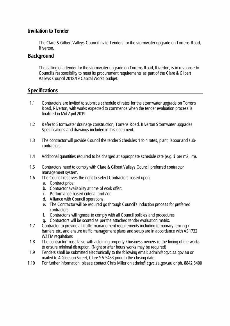
Invitation to Tender
The Clare & Gilbert Valleys Council invite Tenders for the stormwater upgrade on Torrens Road, Riverton.
Background
The calling of a tender for the stormwater upgrade on Torrens Road, Riverton, is in response to Council’s responsibility to meet its procurement requirements as part of the Clare & Gilbert Valleys Council 2018/19 Capital Works budget.
Specifications
1.1 Contractors are invited to submit a schedule of rates for the stormwater upgrade on Torrens Road, Riverton, with works expected to commence when the tender evaluation process is finalised in Mid-April 2019.
1.2 Refer to Stormwater drainage construction, Torrens Road, Riverton Stormwater upgrades
Specifications and drawings included in this document. 1.3 The contractor will provide Council the tender Schedules 1 to 4 rates, plant, labour and sub-
contractors. 1.4 Additional quantities required to be charged at appropriate schedule rate (e.g. $ per m2, lm).
1.5 Contractors need to comply with Clare & Gilbert Valleys Council preferred contractor
management system. 1.6 The Council reserves the right to select Contractors based upon;
a. Contract price; b. Contractor availability at time of work offer; c. Performance based criteria; and / or, d. Alliance with Council operations. e. The Contractor will be required go through Council’s induction process for preferred
contractors f. Contractor’s willingness to comply with all Council policies and procedures g. Contractors will be scored as per the attached tender evaluation matrix.
1.7 Contractor to provide all traffic management requirements including temporary fencing / barriers etc. and ensure traffic management plans and setup are in accordance with AS1732 WZTM regulations
1.8 The contractor must liaise with adjoining property / business owners re the timing of the works to ensure minimal disruption. (Night or after hours works may be required)
1.9 Tenders shall be submitted electronically to the following email: [email protected] or mailed to 4 Gleeson Street, Clare SA 5453 prior to the closing date.
1.10 For further information, please contact Chris Miller on [email protected] or ph. 8842 6400

Pricing Schedule
2.1 Price payable by the Council for the Services as quoted in the pricing schedule and as agreed between the Council and the Quote and in keeping with Payment Terms Negotiated with the Council.
2.2 This purchase price will be authorised once the invoice for work has been authorised by the Works & Infrastructure Manager.
2.3 Prices must be listed exclusive of GST unless shown otherwise. 2.4 Provide a breakdown of the costs for each location activity on the attached Schedule of Rates,
plant, labour and sub-contractors and a detailed program of the works including the proposed start and completion dates of the project.
Work, Health and Safety Requirements
Formal Work Health & Safety Requirements
Under the Work Health & Safety Act 2012 (SA), the Council has a duty as a “person conducting a business or undertaking” (PCBU) to provide and maintain, so far as is reasonably practicable, a safe working environment for its employees, tenderers, contractors, sub-contractors, consultants, visitors and members of the public. To align with the Councils’ WHS duties, the successful Tenderer must comply and ensure that others comply with the following: 1. The Tenderer engaged in providing the Services must identify and discharge their own duties as a
PCBU; 2. The Tenderer must ensure through a documented and systematic approach, that it complies with
any Acts, regulations, local laws and by-laws or Guidelines applicable to the performance of the Services; and
3. The Tenderer must comply with any reasonable directions of the Council’s Contract Representative relating to safety and environmental matters if they arise.
General Advice It is the responsibility of the Contractor to comply with relevant state WHS legislation, relevant Codes of Practice, Australian Standards and for reporting unsafe or unsatisfactory working conditions, hazards and incidents. The Contractor is to complete and provide all relevant Safe Work Method Statement (SWMS), Job Safety Analysis (JSA), Risk Assessment (RA) or Safe Work Instruction (SWI) paperwork to the Council. Safe Work Method Statement (SWMS) is a document which records the significant (prescribed) information relating to WHS for a construction project. Job Safety Analysis (JSA) simply means looking at the work task and considering what is the safest way to complete it. It is a way of becoming aware of the hazards involved in doing the job and taking action to prevent an injury. The JSA form will allow you to record that the safety assessment has been carried out.
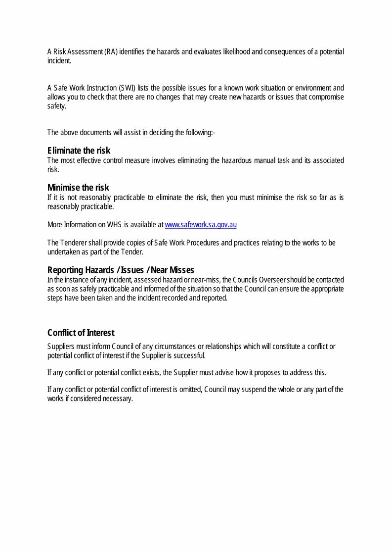
A Risk Assessment (RA) identifies the hazards and evaluates likelihood and consequences of a potential incident. A Safe Work Instruction (SWI) lists the possible issues for a known work situation or environment and allows you to check that there are no changes that may create new hazards or issues that compromise safety. The above documents will assist in deciding the following:- Eliminate the risk The most effective control measure involves eliminating the hazardous manual task and its associated risk. Minimise the risk If it is not reasonably practicable to eliminate the risk, then you must minimise the risk so far as is reasonably practicable. More Information on WHS is available at www.safework.sa.gov.au The Tenderer shall provide copies of Safe Work Procedures and practices relating to the works to be undertaken as part of the Tender. Reporting Hazards / Issues / Near Misses In the instance of any incident, assessed hazard or near-miss, the Councils Overseer should be contacted as soon as safely practicable and informed of the situation so that the Council can ensure the appropriate steps have been taken and the incident recorded and reported. Conflict of Interest Suppliers must inform Council of any circumstances or relationships which will constitute a conflict or potential conflict of interest if the Supplier is successful.
If any conflict or potential conflict exists, the Supplier must advise how it proposes to address this.
If any conflict or potential conflict of interest is omitted, Council may suspend the whole or any part of the works if considered necessary.
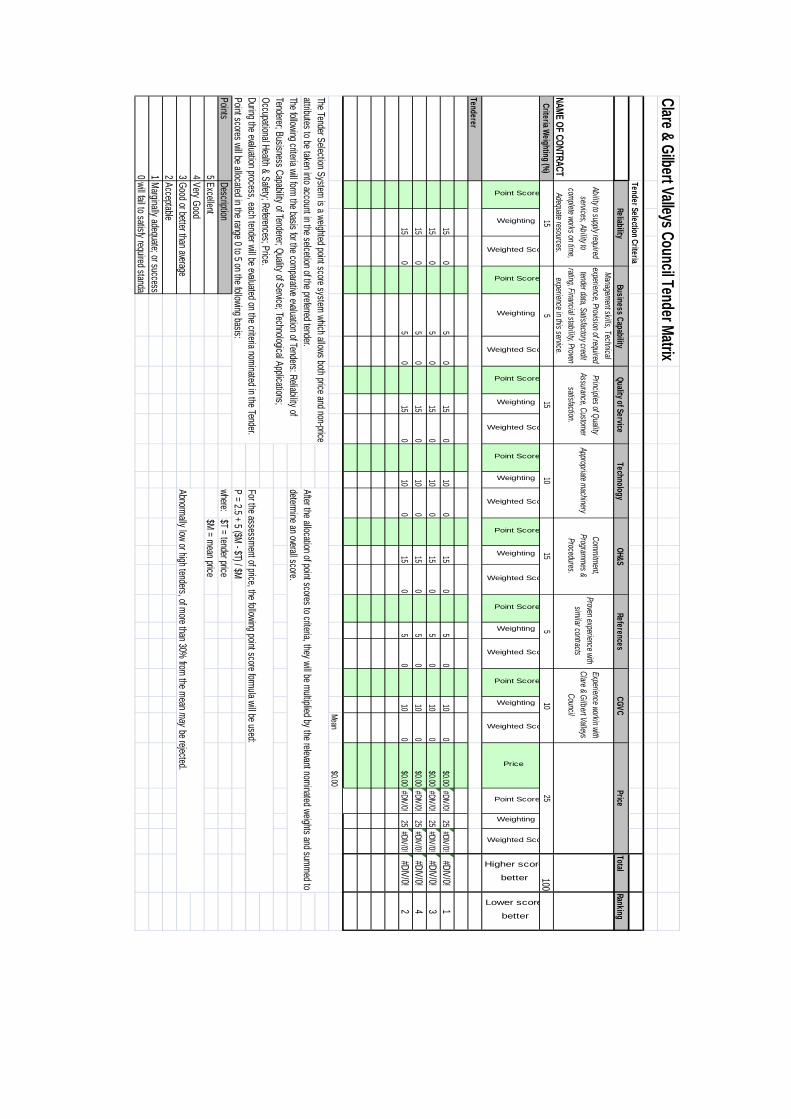
Clare & Gilbert Valleys Council Tender Matrix
Tender Selection CriteriaTotal
Ranking
NAME OF CONTRACTCriteria Weighting (%)
100
Point Score
Weighting
Weighted Sco
Point Score
Weighting
Weighted Sco
Point Score
Weighting
Weighted Sco
Point Score
Weighting
Weighted Sco
Point Score
Weighting
Weighted Sco
Point Score
Weighting
Weighted Sco
Point Score
Weighting
Weighted Sco
Price
Point Score
Weighting
Weighted Sco
Higher score
better
Lower score
better
Tenderer
150
50
150
100
150
50
100
$0.00#DIV/0!
25#DIV/0!
#DIV/0!1
150
50
150
100
150
50
100
$0.00#DIV/0!
25#DIV/0!
#DIV/0!3
150
50
150
100
150
50
100
$0.00#DIV/0!
25#DIV/0!
#DIV/0!4
150
50
150
100
150
50
100
$0.00#DIV/0!
25#DIV/0!
#DIV/0!2
Mean$0.00
Pointswhere:
$T = tender price5
$M = mean price43210
Marginally adequate; or success
will fail to satisfy required standar
DescriptionExcellentVery Good
The Tender Selection System is a weighted point score system which allows both price and non-price attributes to be taken into account in the selcetion of the preferred tender.
After the allocation of point scores to criteria, they will be multiplied by the relevant nominated weights and summed to determine an overall score.
The following criteria will form the basis for the comparative evaluation of Tenders: Reliability of Tenderer; Busisness Capability of Tenderer; Quality of Service; Technological Applications; Occupational Health & Safety; References; Price.
For the assessment of price, the following point score formula will be used:During the evaluation process, each tender will be evaluated on the criteria nominated in the Tender. Point scores will be allocated in the range 0 to 5 on the following basis:
Acceptable
P = 2.5 + 5 ($M - $T) / $M
155
1510
Abnormally low or high tenders, of more than 30% from the mean may be rejected.
Good or better than average
155
2510
Price
Ability to supply required services, Ability to
complete works on time, Adequate resources.
Management skills, Technical experience, Provision of required
tender data, Satisfactory credit rating, Financial stability, Proven
experience in this service.
Principles of Quality Assurance, Customer
satisfaction.Appropriate machinery
Commitment, Programmes &
Procedures.
Proven experience with similar contracts
ReliabilityBusiness Capability
Quality of ServiceTechnology
OH&SReferences
CGVC
Experience workin with Clare & Gilbert Valleys
Council

T03-2019 Torrens Road, Riverton Stormwater Upgrade
Tenderer’s Details (complete and return)
1. Name of Respondent
State in full the name(s) of the Respondent(s) and trading names
ABN
2. Contact Person
3. Registered Address
4. Postal Address
5. Telephone
6. Fax
7. Email
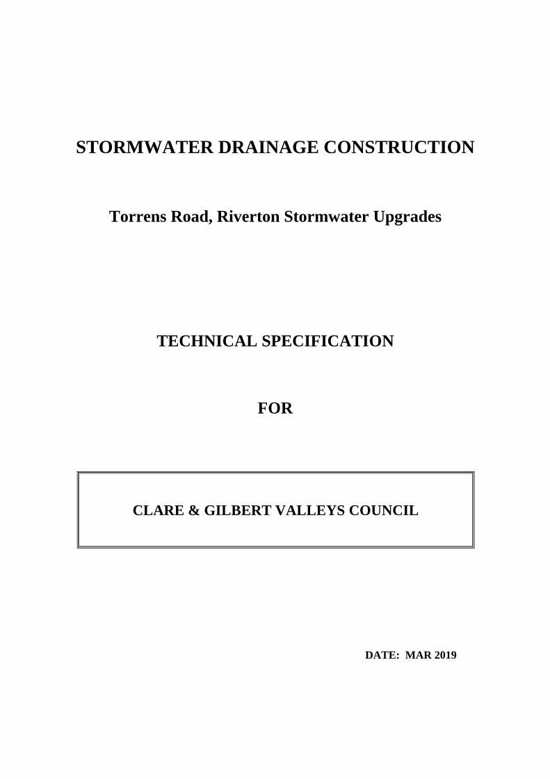
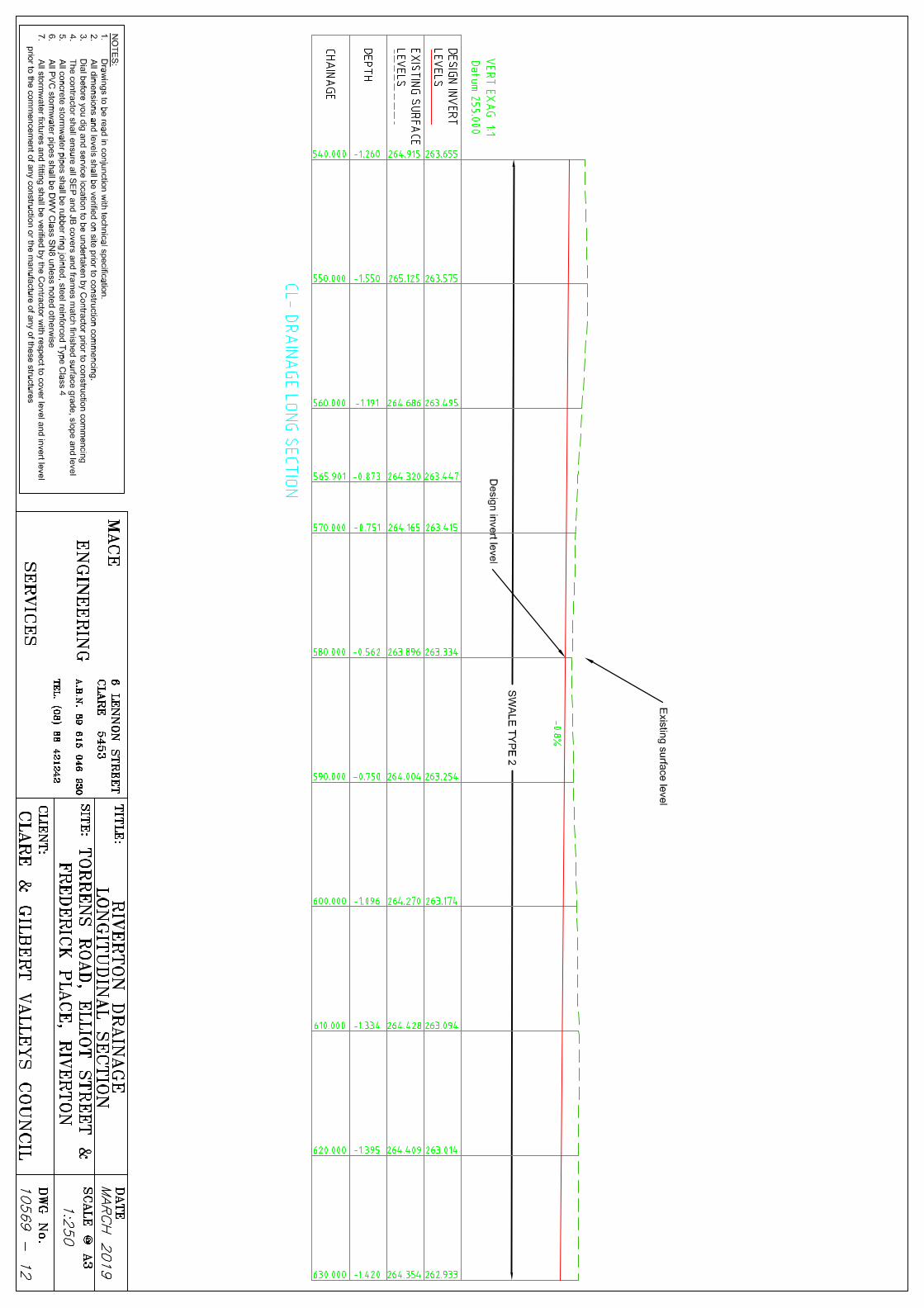
STORMWATER DRAINAGE CONSTRUCTION
Torrens Road, Riverton Stormwater Upgrades
TECHNICAL SPECIFICATION
FOR
CLARE & GILBERT VALLEYS COUNCIL
DATE: MAR 2019

Page 1
TECHNICAL SPECIFICATION
CONTENTS 1. General 2. Site Description 3. Project Description 4. Location of Utility Services 5. Tree Removal 6. Materials 7. Removal Of Existing Pavement 8. Excavation 9. Placing Of Culverts 10. Precast Concrete Drainage Structures 11. Culverts At Minor Accesses And Junctions 12. Backfill 13. Concrete 14. Reinstatement Of Existing Pavements 15. Property Drainage Connections 16. Damage To Culverts And Drainage Structures 17. Sedimentation 18. Test Procedures 19. Hold Points 20. Verification Records And Requirements 21. Payment 1. GENERAL This specification details requirements for the installation of pipe drains, box culverts, kerbing, junction boxes, side entry pits, and pavement reinstatement. Works shall be carried out in accordance with this specification and the detailed design drawings. 2. SITE DESCRIPTION The site is located in the township of Riverton and involves the drainage upgrades around the Torrens Road / Frederick Place area. The stormwater drainage commences on Torrens Road & continues through a series of pipes, junction boxes and box culverts until the outlet in the existing watercourse near the Gilbert River. The site works will take place predominantly throughout road reserves and through 1 easement on private property. Potential tenders are encouraged to make a site visit prior to submitting tenders for the works.
Page 2
3. PROJECT DESCRIPTION The project includes the works detailed on the Drawing Nos 10569-01 to 10569-16 and should be submitted in line with the tender schedule provided. The intent of the drainage works is to upgrade the underground drainage systems on Torrens Road and Frederick Roads in Riverton to alleviate potential flooding issues. The scope of works shall be as described on the drawings, in the schedule, and by this specification, which shall include:
• Preliminaries – Site establishment including setting out of works, ongoing traffic management and supervision
• Locating and depthing of services prior to construction
• Delivery and disposal of existing kerbing, footpath, pipework and bitumen (disposal fees allowance)
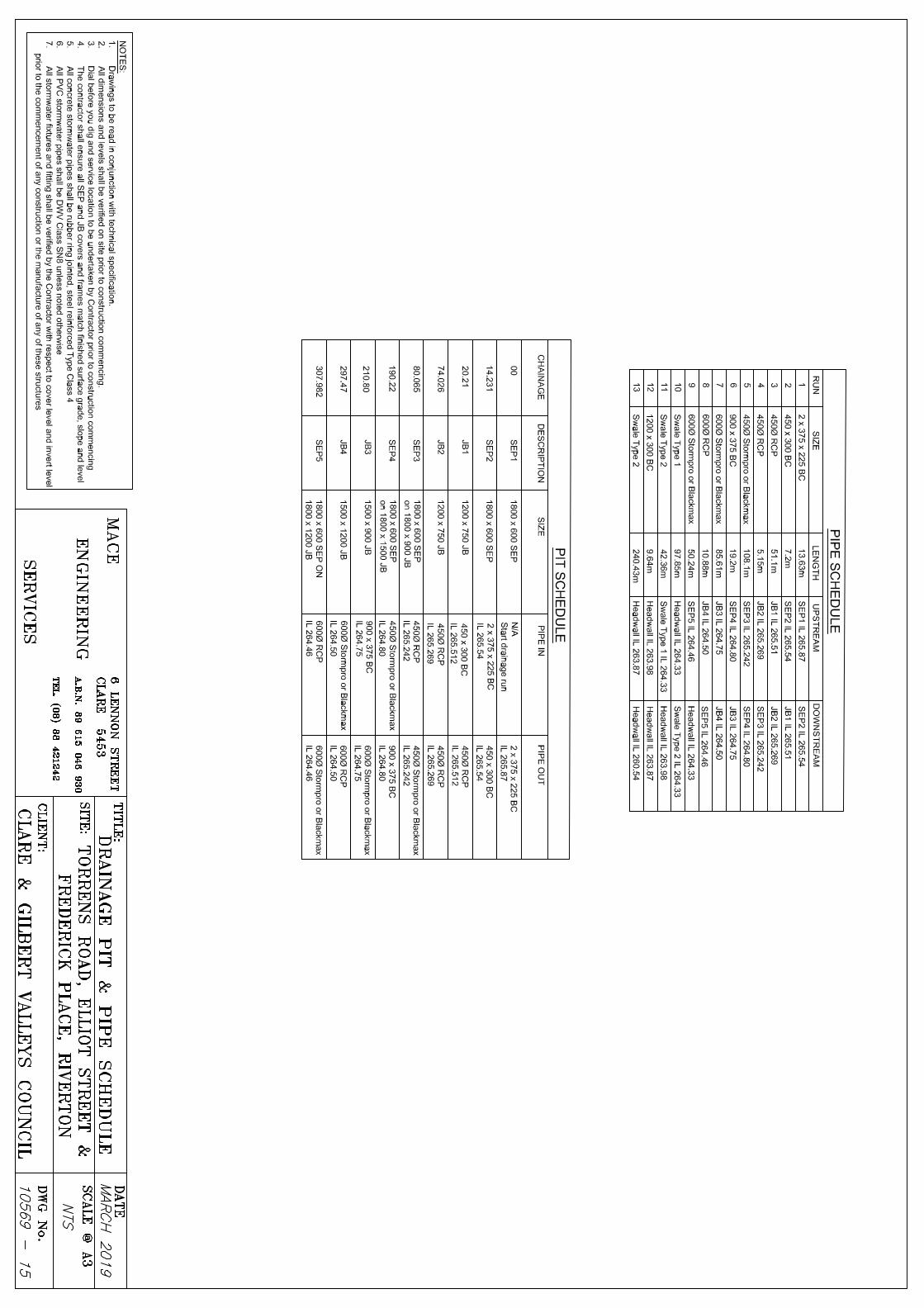
• RUN 1 – FROM SEP 1 TO SEP 2 – Trenching, supply, installation and backfill of 2 x 375mm Box Culverts - Allow for Reinstatement of DPTI road crossing as per DPTI specification
Page 3
• RUN 2 - FROM SEP 2 to JB 1 - Trenching, Supply, installation and backfill of 1 x 450mm Box Culvert Allow for Reinstatement of Council Footpath and road to match in with existing
• RUN 3 - FROM JB 1 to JB 2 - Trenching, Supply, installation and backfill of 1 x 450mm RCP - Allow for Reinstatement of Council road to match in with existing
• RUN 4 - FROM JB 2 to JB 3 - Trenching, Supply, installation and backfill of 1 x 450mm
RCP - Allow for Reinstatement of Council road to match in with existing
Page 4
• RUN 5 - FROM JB 3 to SEP 4 - Trenching, Supply, installation and backfill of 1 x 450mm Pipe – Can be Stormpro or BlacMax pipes as installation is in verge area - Allow for Reinstatement of Council road reserve to match in with existing
• RUN 6 - FROM SEP 4 to JB 4 - Trenching, Supply, installation and backfill of 1 x 900 x
375 Box Culvert Allow for Reinstatement of Council Footpath and road to match in with existing
• RUN 7 - FROM JB 4 to JB5 - Trenching, Supply, installation and backfill of 1 x 600mm
Pipe - Can be Stormpro or BlacMax pipes as installation is in verge area - Allow for Reinstatement of Council road reserve to match in with existing
Page 5
• RUN 8 - FROM JB 5 to SEP 5 - Trenching, Supply, installation and backfill of 1 x 600mm
RCP - Allow for Reinstatement of Council road to match in with existing
• RUN 9 - FROM SEP 5 to Outlet at Open Drain - Trenching, Supply, installation and backfill of 1 x 600mmPipe - Can be Stormpro or BlacMax pipes as installation is in verge area - Allow for Reinstatement of Council road to match in with existing
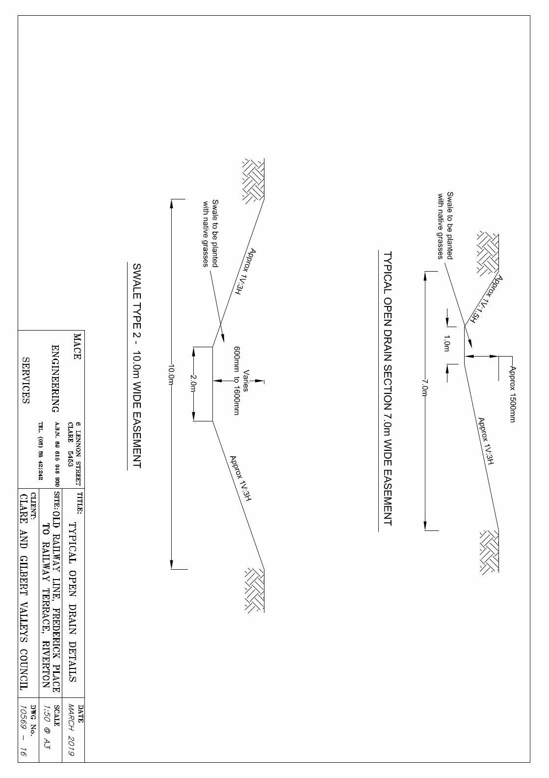
• RUN 10 - SWALE TYPE 1 - Excavate swale and dispose of material within 10km of site
Page 6
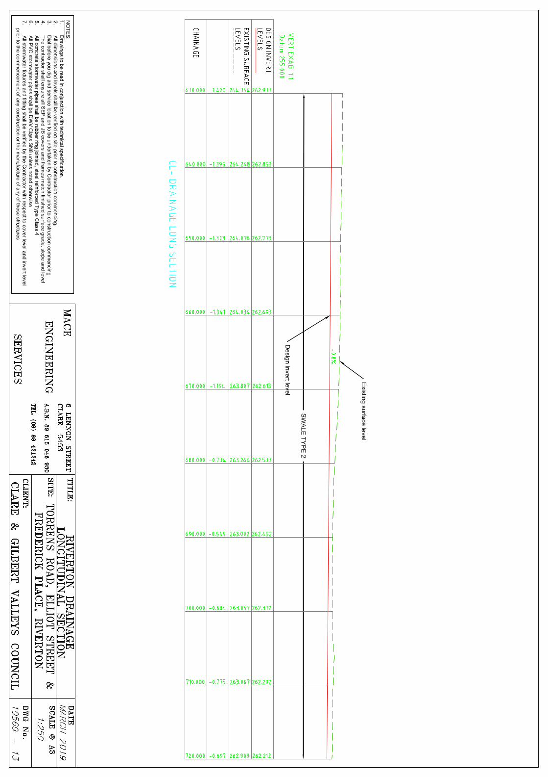
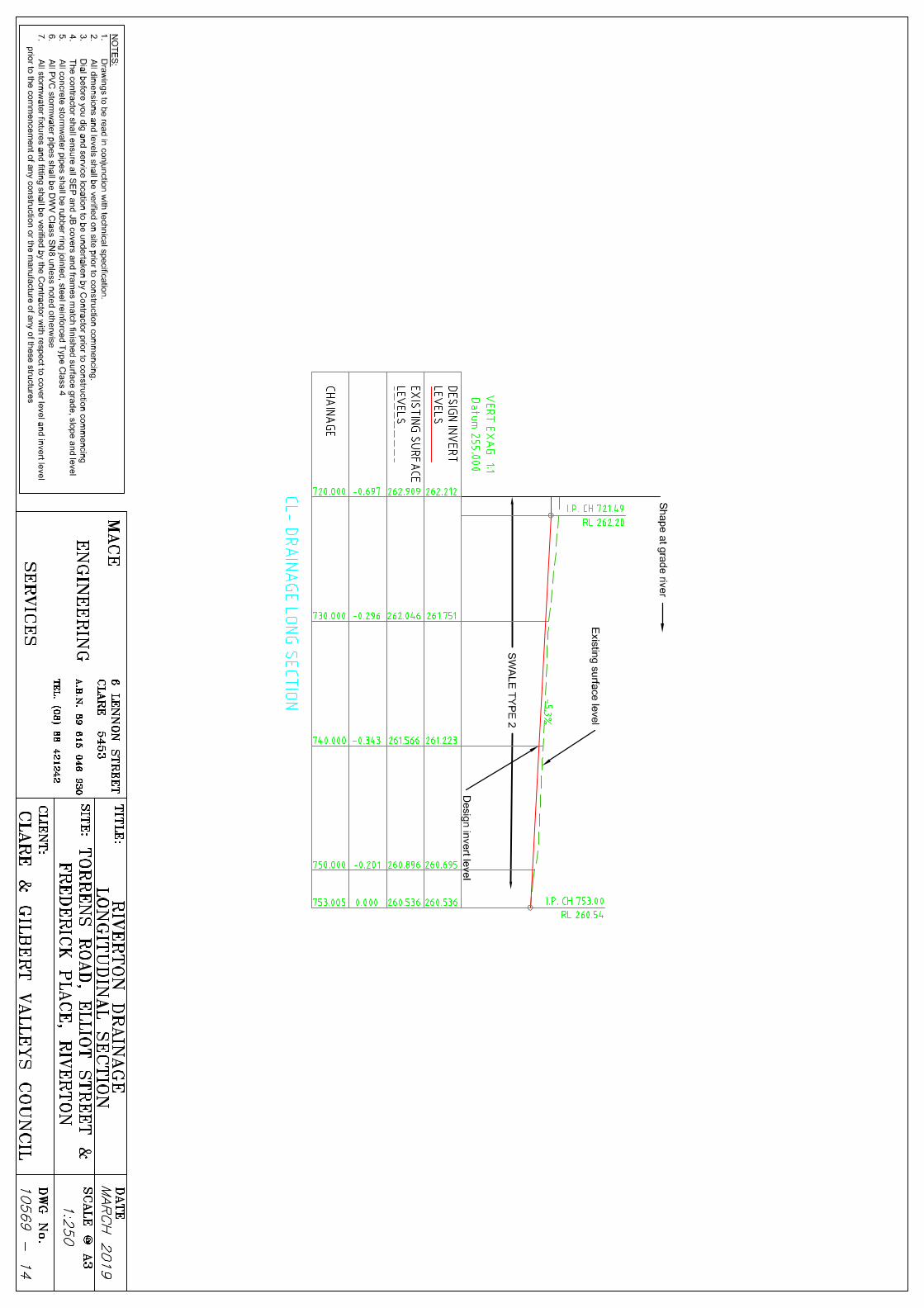
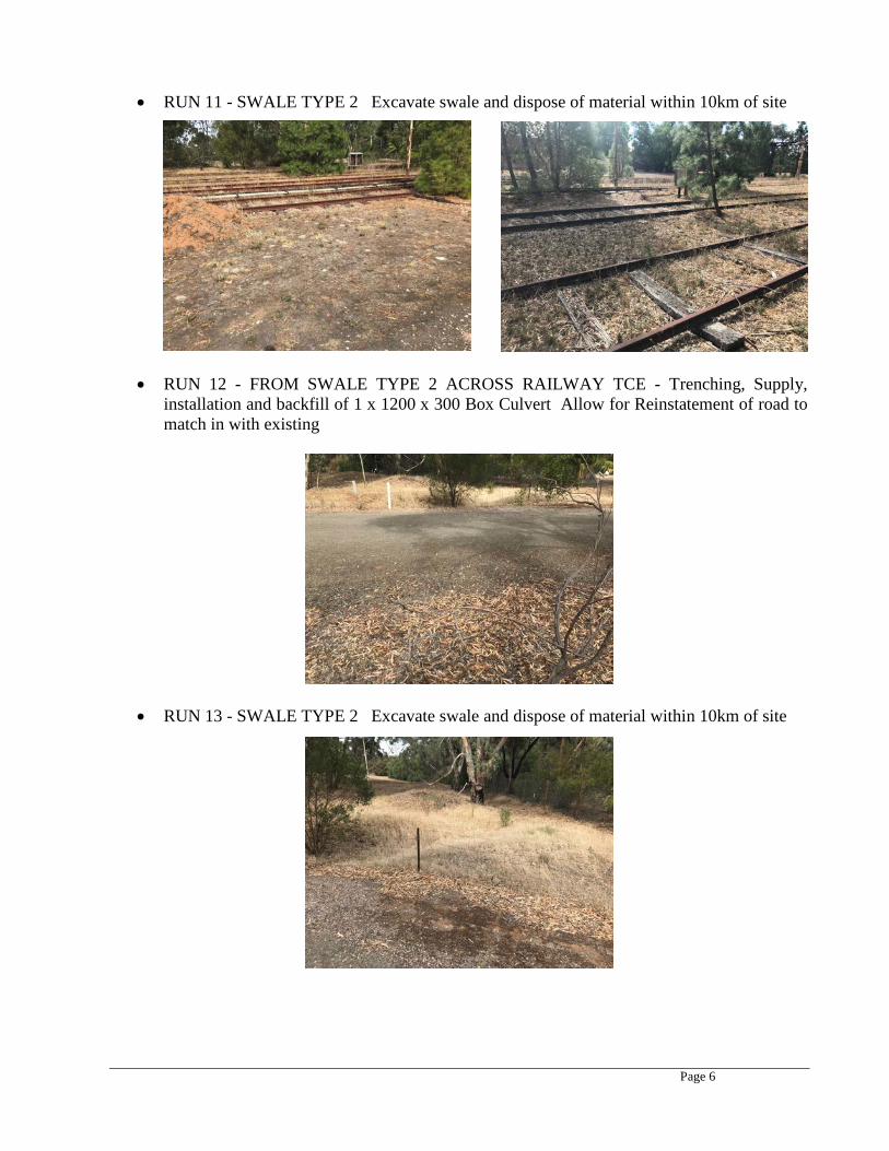
• RUN 11 - SWALE TYPE 2 Excavate swale and dispose of material within 10km of site
• RUN 12 - FROM SWALE TYPE 2 ACROSS RAILWAY TCE - Trenching, Supply,
installation and backfill of 1 x 1200 x 300 Box Culvert Allow for Reinstatement of road to match in with existing
• RUN 13 - SWALE TYPE 2 Excavate swale and dispose of material within 10km of site

Page 7
• Supply and installation of 1800 x 600 Side Entry Pit (SEP) Pits, Surrounds and Lids as per DPTI Specifications
• Supply and installation of Junction boxes - various sizes as per drawings
• Supply and installation of headwall at outlet of 600 dia pipe to Swale Type 1
• Installation of 150mm Upright kerb and water table to new SEP locations
• Cut existing railway track through Swale Type 2 area and store on site
• Respread available stripped topsoil over new swale area
• Compaction testing, QA documentation, CCTV of installed lines & Survey As-Builts in accordance with DPTI Specifications
Page 8
4. LOCATION OF UTILITY SERVICES 4.1 General
The location of utility services shall be undertaken in accordance with DPTI Master Specification, Part 112, “Utility Services”.
“Utility Services” means any infrastructure directly associated with:-
• Transmitting electrical or telecommunications; • Transporting gases, liquids or solids (including water, sewerage, fuel and
waste); or • Communications/ signalling for railway transportation.
“Service Authority” means any government, semi-government or private organisation responsible for the care and/ or control of Utility Services.
The Principal is not liable for any damage to Utility Services or claims from Service Authorities resulting from the Contractor’s failure to comply with the requirements of this Part.
Page 9
4.2 Liaison with Service Authorities
The Contractor must regularly inspect the Site to check whether any Utility Services, not previously identified, are in existence and to verify that those Utility Services which have been identified are correctly located.
Where any Utility Service has been identified which may affect the work under the Contract, the Contractor must:-
• Prior to commencement of work on Site, arrange a site meeting to be attended by the Contractor, the Superintendent and representatives from the relevant Service Authorities;
• Liaise with the relevant Service Authorities to confirm the location of the Utility Services and take all reasonable steps to determine the accurate location of the Utility Services;
• Liaise with Service Authorities or any industry regulator regarding their requirements for clearance, cover and/ or temporary protection;
• Allow Service Authorities or their authorized representatives reasonable access to the site for the purpose of identifying, relocating, modifying or installing Utility Services;
• Comply with any reasonable requirement of a Service Authority regarding the protection of a Utility Service;
• Keep the Superintendent fully informed of the progress and status of its liaison
or negotiations with Service Authorities and works associated with Utility Services; and
• Ensure that the Contractor’s program identifies any activities and constraints
associated with Utility Services. 4.3 Information Provided by the Principal
The location of Utility Services (either existing or proposed) shown on any drawings or other documentation provided by the Principal:-
• Is approximate only; and
• Cannot be relied upon as being sufficiently accurate to carry construction
activities without further steps to determine the accurate locations.
Page 10
5. TREE REMOVAL To carry out the works no tree removal should be required. Trimming of any existing trees will be carried out and allowed for in this contract of the stormwater works. The contractor shall ensure that no further trees or vegetation is disturbed while carrying out the works. 6. MATERIALS All materials required for the construction of the drainage works detailed in this specification, the tender schedule and detailed drawings shall be supplied by the contractor and in accordance with the appropriate AS or specification . Sand required for bedding and backfill shall be supplied free of charge by Council from the Saddleworth Depot. The contractor shall allow to load and deliver the sand from the Saddleworth Depot to the worksite. The sand shall only be used for bedding and backfill to max 300mm above the pipe. The contractor shall allow for any materials required for reinstatement above the sand in the tender document.
STORMWATER DRAIN CONSTRUCTION 6.1 Standard Specification References
The latest editions, including all revision of the standards referred to in this section, shall form the basis for the performance of the work covered by this section.
6.2 Materials 6.2.1 Mass Concrete
Mass concrete to be used in bedding or backfill operations shall consist of cement, fine aggregate and coarse aggregate in the ration of 1:3:6 by volume, mixed by mechanical means with the minimum amount of water necessary to render the mix workable.
6.2.2 Cement Mortar
Cement mortar for surface reinstatement on concrete structures, pipe-joint filling or other purposes shall consist of one part by volume Portland cement to two parts by volume fine aggregate, properly mixed by mechanical means or by hand with the minimum amount of water necessary to render the mix workable.
Page 11
6.2.3 Quarry Products
6.2.3.1 Bedding and Backfilling Sand
General
This Specification is in accordance with the DPTI Standard Specification PM 61-64 generally.
Source and Impurities
The sand shall be a pit or dune sand, or may be obtained from the crushing of rock suitable for concrete aggregates and shall be free from the seeds and bulbs of noxious weeds as proclaimed in South Australia by Regulations under the ‘Weeds Act’, 1956.
Grading
R40/3 metric series sieve (mm) 6.7 0.075 Percentage passing 95 – 100 0 – 10
Soil Constants
The sand shall be non-plastic, unless otherwise noted on the accompanying Drawings.
6.2.3.2 Granular Bedding Material
General
This material shall be 10 – 7mm chippings in accordance with the DPTI Specification Sealing Aggregate, SA 10 - 7, generally. R40/3 metric series sieve (mm) 13.2 9.5 6.7 4.75 Percentage passing 100 85 – 100 0 – 15 0 – 3 Los Angeles Value not to exceed 25%
6.2.3.3 Stone for Stone Pitching
Stone for this purpose shall be clean, hard, sound, durable, free from adherent coatings, mica, shale and similar laminated material and any other foreign matter or shall contain insufficient quantities of these to produce an adverse effect upon the usage of the material. The minimum volume of each stone shall be 0.01m3 with at least one face of 0.06m2
minimum area.
Page 12
6.2.4 Backfilling Soil
Where soil is permitted to be used for backfilling above the pipe, it shall be local material won from excavation and substantially free from stones, clay lumps, vegetation and other deleterious substances. These areas shall be restricted to soft landscaped areas only.
6.2.5 Reinforced Concrete Pipes
Steel reinforced concrete pipes shall be Class ‘4’ spigot and socket jointed with rubber ring joints or as specified on accompanying Drawings.
All concrete pipes shall be manufactured in accordance with AS/NZS 4058.
All concrete pipes shall be installed by the Contractor in accordance with AS/NZS 3725.
Steel reinforced concrete box culvert sections, where required, shall be of the crown type and consist of precast crowns with interlocking joints and precast or cast in-situ baseplates as nominated on the Drawings.
Bends, junctions or other fabricated accessories shall be manufactured from material of identical composition, or as shown on the Drawings, or as approved by the Superintendent.
All units shall be free from ships, cracks and any deformities which, in the opinion of the Engineer, are likely to affect in-service performance.
6.2.6 Rigid (Unplasticised) Polyvinyl Chloride (uPVC) Pipes
Allotment drains 225 diameter or less may be constructed of PVC. Pipes shall be the nominal internal diameters as shown on the accompanying Drawings and shall comply with AS1260, parts 1 to 4. uPVC pipes of equal quality and non-standard dimension, ie. larger internal diameter and greater wall thickness may be approved by the Engineer.
6.2.7 Precast Concrete Drain Appurtenances
Where the Drawings indicate that precast side entry pits, manholes, deflector aprons and similar structures may be approved as alternatives to the detail shown, the Contractor shall submit the Drawings and Specifications from the manufacturer to the Engineer for approval prior to their installation. Samples of units may be required to be supplied by the Contractor at their cost for testing for structural sufficiency.
Page 13
6.2.8 Access Covers and Frames, etc
The size, class and loading factor for each unit, where applicable, shall be nominated on the accompanying Drawings.
Side entry pit covers shall consist of a cast iron surround with concrete in-fill as manufactured by P.C.P./Cooke Precast Pty Ltd, or other manufacture approved by the Council.
Manhole covers and grating shall be P.C.P./Cooke Precast Pty Ltd or other manufacture approved by the Council and Local Government Authority.
6.2.9 Drainage Pipe Separation
All drainage pipes shall have a minimum spacing between pipes running parallel and crossing over each other as follows:
• Reinforced concrete pipes = 300mm minimum • PVC drains = 150mm minimum
Any pipe clashes during construction must be reported to the Superintendent for consideration or redesign.
6.2.10 Drainage Pipe Cover
The Contractor must confirm the pipe class specified on the accompanying drawings by the pipe supplier prior to delivery and installation of the drains.
The Contractor shall take particular care with placement of the bedding, haunch, side zone, overlay and backfill materials to ensure the pipe supplier’s installation guidelines and recommendations are followed.
Avoid damaging the pipe by excessive impact from heavy compact equipment.
Bring up the haunch and size zones on both sides of the pipe evenly to ensure pipe will not easily slide out of alignment.
Avoid running heavy construction equipment over the pipes until sufficient cushion of material has been placed, approximately 300mm for normal material.
When using vibrating compaction equipment allow 500mm cushion of material over the pipe or alternatively turn off the vibrator until this level is reached.
Notwithstanding, the Contractor must obtain advice from the pipe supplier for best practice installation procedure.
Page 14
Any dislodgement or cracking of a drainage pipe identified during the process will require removal and replacement of a new section of pipe at the Contractor’s expense.
7. REMOVAL OF EXISTING PAVEMENT This clause only applies where excavation takes place in an existing pavement which is to be retained. The pavement shall be saw cut prior to excavation. Any additional breakage of the existing pavement edge shall be cut square to the edge of the excavation prior to reinstatement. All saw cutting shall be dampened by water to reduce dust and any resultant slurry shall be collected and disposed of in accordance with the requirements of the Environmental Protection Act. The slurry must not enter stormwater drainage systems or dry out on the road surface. Removal of existing pavements shall comply with the following: - The trench shall be saw cut to the full depth of the existing sprayed bituminous surface. - Longitudinal saw cuts shall not be positioned within the wheel path. 8. EXCAVATION All excavation shall be undertaken in accordance with DPTI Master Specifications Part R07 “Trench Excavation and Backfill”. All excavation shall be of sufficient width to allow for safe and practical working, including the proper placing and subsequent removal of any formwork and for compaction of backfill around the culverts and drainage structures.
The trench shall be excavated to the depth as indicated on the design drawings. 8.1 Support of Utility Services in Excavations
Where Utility Services are encountered in an excavation, the Contractor shall liaise with the appropriate Service Authority to obtain any requirements for support of the Utility Services and comply with those requirements.
8.2 Removal of Existing Culverts and Drainage Structures
Where specified, the Contractor shall remove any existing culverts and drainage structures and backfill the resultant voids in accordance with Clause 12 "Backfill".
Page 15
8.3 Inspection after Excavation
Following completion of excavation, a HOLD POINT shall apply.
If foundation preparation concrete is not to be used, the Contractor shall undertake proof rolling to verify the strength of the subgrade and identify any unsuitable materials. Unsuitable material is defined as material which, in its current position and state, is unsuitable for the support of pavement or layers of fill. It is identified by:
(a) deformation, rutting, softness, yielding, distress or instability under proof rolling or the loading from any construction machinery; or
(b) a visual assessment of its properties, such as organic content or moisture content, which indicates that it will be unsuitable for its intended purpose.
For culverts and drainage structures, 2 passes of a vibrating plate compactor (Wacker Model BPU 3345 or similar) shall be used.
The Contractor shall remove and replace any unsuitable material which has been identified.
8.4 Excavation at Inlets and Outlets
The Contractor shall excavate as necessary to match the culvert invert to the adjoining drainage channels or natural surface.
Unless shown otherwise on the Drawings, the excavation shall be uniformly graded at a maximum grade of 2% or to the boundary of the road reserve, whichever extends the least. The excavation shall be the full width of the culvert apron, with batters not steeper than 6 horizontal to 1 vertical.
9. PLACING OF CULVERTS 9.1 Dimensions
Where culverts terminate at side entry pits, junction boxes and headwalls, the length of the culvert shown on the Drawings is the length measured along the centreline of the culvert units. At other locations, the length of the culverts shown on the Drawings is the plan length measured from centre to centre of drainage structures unless otherwise shown.
Page 16
9.2 Bedding
Bedding shall be Sa-C Type C sand or similar spread to a minimum compacted depth of 100 mm.
The Contractor shall arrange for trials to be conducted to verify a method of achieving the specified compaction. The minimum compacted thickness of bedding for verification purposes shall be 125 mm to enable testing.
Prior to use of the method, a HOLD POINT shall apply.
For pipes, the bedding sand shall be rammed under both sides of the haunches of the pipe to the top of the pipe.
9.3 Placing 9.3.1 Concrete Pipe Culverts
Pipes shall be placed and jointed in accordance with the manufacturer's instructions.
Pipes shall be placed with the female end upstream and with lifting holes (if any) uppermost. Lifting holes in pipes shall be filled with plugs supplied by the pipe manufacturer for that purpose.
9.3.2 Small Box Culverts
Small box culverts shall be placed so that the joints between base slabs are located half way between the joints on the crowns. Mortar or pipe sealant shall be used to seal the joint between the crown units and bases. A bituminised tape (Densopol 60HT or equivalent) shall be used in accordance with the manufacturer's instructions to seal the joints of abutting crown units. Taping shall be done immediately prior to backfilling to minimise the risk of separation of the tape from the concrete surfaces.
Lifting hooks shall be cut off with a cutting disc, with both steel and concrete being ground away at least 5 mm below the surrounding concrete surface. The surface shall then be finished flush with an epoxy putty (Bauer Gemcrete 205 or equivalent) to give a minimum cover of 5 mm over the remnant lifting hook.
Page 17
9.4 Junctions
Where a junction is shown on the Drawings it shall be constructed as a bandaged joint in accordance with Clause 8.6 "Extension of Existing Culverts". Backfill shall not be placed against junctions until the following day.
The construction of the joint shall provide an unobstructed waterway of the specified diameter in each of the pipes after completion of the joint.
9.5 Cutting Culverts
Cutting of culverts to provide appropriate lengths at joints and drainage structures shall be done in such a manner that it does not affect the structural capacity of the culvert. Reinforcement exposed during cutting of culverts shall be painted with a thick highbuild epoxy (Megapoxy P1 or approved equivalent) applied in accordance with the manufacturer's instructions.
10. PRECAST CONCRETE DRAINAGE STRUCTURES 10.1 Scope
Inspection pit covers shall be installed flush with the final surface. 10.2 Foundation Preparation for Drainage Structures
Bedding shall be in accordance with Clause 9.2 "Bedding". Excavation below the specified levels shall be filled with either Sa-C Type C sand or similar and compacted to the same standard as the bedding.
10.3 Joints between Culverts and Precast Drainage Structures
Where a precast drainage structure is used, the external joint with the culvert shall be strengthened with a concrete fillet encircling the culvert at the joint. The fillet shall be a minimum of 100 mm thick 10 MPa concrete (or rapid mix equivalent).
The inside joint shall be rendered flush with the inside wall of the structure with mortar (1 part cement and 3 parts sand) or equivalent.
Page 18
11. CULVERTS AT MINOR ACCESSES AND JUNCTIONS Culverts for side drains under minor accesses and junctions shall be placed in the centre of the side drain with the same grade as the side drain. The culvert shall allow unimpeded flow of water in the side drain. 12. BACKFILL 12.1 General
All Trench Backfill shall be undertaken in accordance with DPTI Master Specifications Part R07 “Trench Excavation and Backfill”.
12.2 Backfill Material
Excavated material having been deemed to be unsuitable by the Superintendent shall not be reused for backfill of trenches below areas of pavement. If the excavated material cannot be reused on the site in an acceptable manner, it shall be removed from the site and disposed of by the Contractor at an appropriate reuse facility, in accordance with the requirements of the Environment Protection Act.
Below pavement, the backfill material shall extend to the underside of the pavement. The backfill material shall be Sa-C Type C sand or similar. Refer to cross section drawing 10208-10. Outside areas of pavement, the backfill material shall be Sa-C Type C sand or similar to a level at least 300 mm above the top of the service after compaction. Unless specified otherwise, excavated material may be used above this level.
12.3 Placing of Backfill
Prior to, and during backfill operations, all loose rubbish and foreign material shall be removed from the excavation. All voids excavated and not occupied by permanent work shall be backfilled.
Sa-C Type C sand backfill or similar shall be compacted alternately on each side of the service. Backfill shall not be placed against any cast-in-place concrete within 48 hours of the placing of concrete. Flooding of sand with water is, by itself, not an acceptable method of compaction.
Page 19
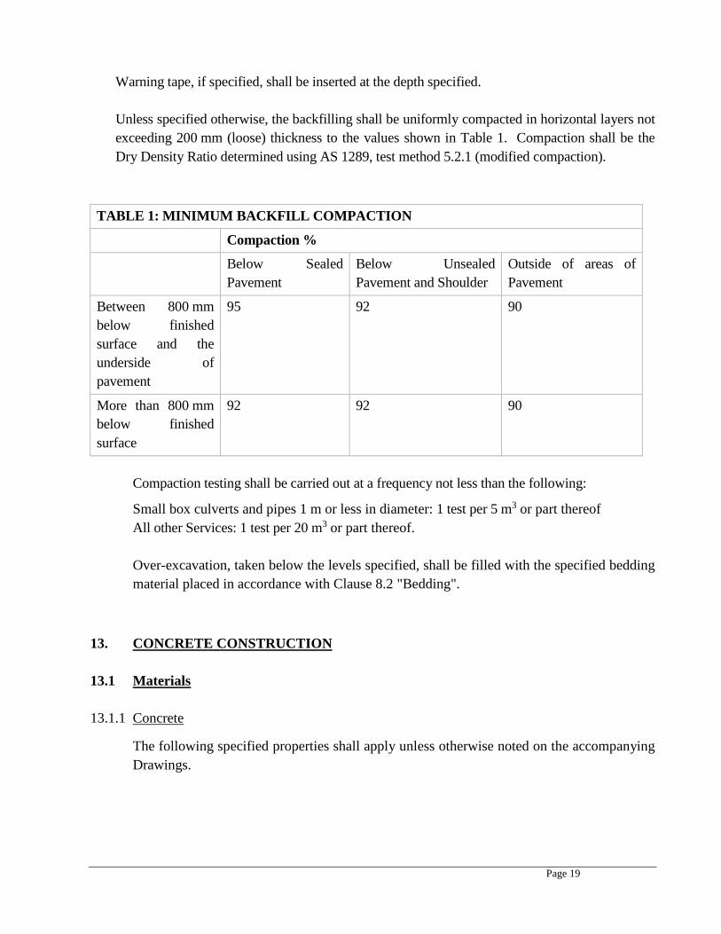
Warning tape, if specified, shall be inserted at the depth specified.
Unless specified otherwise, the backfilling shall be uniformly compacted in horizontal layers not exceeding 200 mm (loose) thickness to the values shown in Table 1. Compaction shall be the Dry Density Ratio determined using AS 1289, test method 5.2.1 (modified compaction).
TABLE 1: MINIMUM BACKFILL COMPACTION
Compaction %
Below Sealed Pavement
Below Unsealed Pavement and Shoulder
Outside of areas of Pavement
Between 800 mm below finished surface and the underside of pavement
95 92 90
More than 800 mm below finished surface
92 92 90
Compaction testing shall be carried out at a frequency not less than the following:
Small box culverts and pipes 1 m or less in diameter: 1 test per 5 m3 or part thereof All other Services: 1 test per 20 m3 or part thereof.
Over-excavation, taken below the levels specified, shall be filled with the specified bedding material placed in accordance with Clause 8.2 "Bedding".
13. CONCRETE CONSTRUCTION 13.1 Materials 13.1.1 Concrete
The following specified properties shall apply unless otherwise noted on the accompanying Drawings.

Page 20
13.1.1.1 Required Properties of Concrete
The following specified properties shall apply unless otherwise noted on the accompanying Drawings.
13.1.1.2 Characteristic Strength
All concrete shall attain a characteristic compressive strength, as defined in Clause 6.1.1.1 of AS3600, F’c at twenty-eight days of 25Mpa or as specifically mentioned on accompanying drawings.
13.1.1.3 Ready-Mixed Concrete
Ready-mixed concrete shall be used for works wherever practicable and shall comply with AS1379. Batch dockets are to be retained in the quality records and submitted with the Quality package.
13.1.1.4 Site-Mixed Concrete
Site-mixed concrete shall only be used for minor works and where approved for use by the Engineer.
Constituents shall comply with AS3972 (Portland cement) AS3972 (Blended cement) AD2758.1 (Aggregates) The mix properties stated below DO NOT apply to concrete made with blended cement. Should blended cement be used, it shall be the responsibility of the Contractor to demonstrate that the mix proportions adopted yield a mix which satisfies the nominal strength requirement. The proportions of fine and coarse aggregate may be adjusted provided the ratio of total aggregate to cement is not changed. Mix Proportions By Mass For Saturated Surface-Dry, Dense Aggregate
Maximum Water / Cement Ration By Mass
Nominal Strength, MPa
Cement 1) Fine Aggregate 2) 0.58 32 Coarse Aggregate 3)
Page 21
13.1.2 Cement Mortar
Cement mortar for surface reinstatement on concrete structures, or other purposes shall consist of one part by volume Portland cement to two parts by volume fine aggregate, properly mixed by mechanical means or by hand with the minimum amount of water necessary to render the mix workable.
13.1.3 Bedding and Backfilling Sand 13.1.3.1 Source and Impurities
The sand shall be a pit or dune sand, or may be obtained from the crushing of rock suitable for concrete aggregates and shall be free from the seeds and bulbs of noxious weeds as proclaimed in South Australia by Regulations under the ‘Weeds Act’, 1956.
13.1.3.2 Grading
R40 / 3 metric series sieve (mm) 4.75 0.075
Percentage passing 95 – 100 0 - 5
13.1.3.3 Soil Constants
The sand shall be non-plastic, unless otherwise noted on the accompanying Drawings.
13.1.4 Reinforcement
Steel reinforcement, where detailed on the accompanying Drawings, shall comply with AS1302 or AS1304 as applicable. A HOLD POINT shall apply.
13.2 Construction 13.2.1 General
The details and dimensions of kerb profiles and other concrete structures are as shown on the DPTI standard drawing S4070 Sheet 7.
The Engineer, whenever possible, shall supply copies of the Standard Drawings to the Contractor. However, it shall be the responsibility of the Contractor to ensure that Standard Drawings used are of current issue for the specific Council area.
Page 22
13.2.1.1 Testing
Project control testing shall be carried out in accordance with Section 20 of AS3600 at the discretion of the Superintendent.
The testing laboratory shall be: as nominated by the Contractor.
The contractor shall inform the laboratory at least twenty-four hours in advance of concrete construction taking place.
13.2.2 Formwork
Before placing concrete, formwork shall be clean, debris shall be removed from places to be occupied by the concrete, and formwork shall be thoroughly wetted. Formwork shall conform to the shapes, lines and dimensions of the concrete as shown on the accompanying Drawings. The surface of all formwork in contact with concrete shall be treated with a proprietary brand of form oil or other method approved by the Engineer and shall be substantial and mortar-tight to prevent leakage of mortar. Supports and bracing shall be sufficient to prevent deflection or distortion during concrete placement or thereafter when subject to incidental construction loads.
For kerb and watertable and similar construction, rigid steel longitudinal sections of formwork shall not be used for curved alignment in accordance with the following:
HORIZONTAL (PLAN) ALIGNMENT: Where the radius is less than one hundred metres; VERTICAL (PROFILE) ALIGNMENT: Where, over any length of 6.1 metres, the difference between the average value of the end elevations and the mid-point elevation exceeds 50mm.
13.2.3 Reinforcement
The reinforcement shall be supported off the formwork by means of concrete blocks, or other approved methods, to ensure that the specified clear cover is obtained. No timber spacers shall be permitted. Laps in straight bars shall be 600mm minimum and 400mm minimum for hooked bars.
Fabric shall be lapped 250mm minimum.
13.2.4 Concrete Cover
The minimum clear concrete cover to all reinforcing steel and embedded fixtures shall be 65mm and as shown on the accompanying Drawings.
Page 23
13.2.5 Placing and Compaction
No concrete shall be placed until the relevant reinforcement and formwork has been inspected and approved by the Superintendent.
Concrete placing shall not proceed when the broadcast (i.e. Shade) temperature for that particular locality exceeds 32oC or when surface damage by rainfall is likely. Plastering is not an acceptable repair for rain damaged concrete. The Engineer shall determine when concreting shall cease and recommence, and may require removal and replacement, at the Contractor’s expense, of concrete poured in contravention of such instructions.
Concrete shall be placed in the formwork as near as practicable to its final position to avoid segregation.
During and immediately following placing, concrete shall be moved into all corners and angles of the formwork and thoroughly compacted.
No concrete which has partially hardened or has been mixed for more than 1.5 hours shall be used. The retempering or mortar or concrete, by the addition of cement, aggregate or water, or by remixing shall not be permitted.
Construction of kerb and watertable by machine methods shall be acceptable provided the requirements regarding control joints, allotment drainage outlets and other relevant clauses of this Specification are met, and the Contractor has the prior approval of the Local Government Authority for the use of a machine for such purposes.
13.2.6 Control Joints
Where the placement of concrete is interrupted for a period of time sufficient to allow initial set to take place, construction joints shall be formed to the details and locations as shown on the accompanying Drawings or as instructed by the Engineer.
In kerb and gutter and similar works, construction joints shall be located at the nearest two metre (nominal) contraction joint location and shall be avoided in vehicular entranceways, pram ramps, and return radii at road junctions.
Prior to placing concrete against the surface of hardened concrete at a construction joint, the joint surface shall be brushed, scabbled or otherwise treated to remove thoroughly all laitance and other deleterious deposits.
Contraction joints shall be formed perpendicular to the line of the work in paving, kerb and watertable and other structures as detailed on the accompanying Drawings. Joints in paving shall be at least one third the depth of the section.
Page 24
Joints in kerb and watertable or similar construction shall be cut a minimum of 50 per cent (50% of the area of the section and at the limits of vehicular entranceways, pram ramps, side entry pit aprons and other changes of section unless noted otherwise. The resultant slot in the section shall be tooled to a depth of not less than 20mm to produce a neat groove on not less than 5mm in width.
13.2.7 Surface Finish and Tolerances
The surface shall be floated smooth and true to the required elevations and grades. The exposed surfaces of concrete structures, excluding the wearing surface of paving, shall be finished with a steel float and be smooth and uniform in colour when dry. Paving shall present a regular broomed or woodfloat appearance on the wearing face and smooth, off-form, or steel-floated finish on other exposed surfaces.
Surface finishing shall be carried out over contraction joints in kerb and watertable, with no tooling of the joint.
The thickness of the components of concrete structures, excluding kerb and watertable, shall not be less than the dimensions shown on the accompanying Drawings at any point. The dimensions of the structure shall be ± 15mm.
For kerb and watertable, spoon drains, vehicular entranceways, pram ramps and other similar construction, the tolerances shall be:
In Horizontal Alignment : ± 10mm
In Elevation : + 0 - 3mm provided that between successive bays or a construction joints, steps in the horizontal or vertical (elevation) alignment do not exceed 2mm.
13.2.8 Removal of Formwork
Formwork shall not be disturbed nor removed until, in the opinion of the Engineer, the concrete has hardened sufficiently or is capable of adequately supporting any temporary superimposed loads placed upon it before attainment of the specified characteristic compressive strength. Surface defects such as honeycomb patches, blowholes, mechanical damage, cracking and crazing apparent after the formwork has been removed, shall be repaired provided that, in the opinion of the Engineer, such defects are not structurally significant in which case the concrete shall be cut out and replaced.
Page 25
Making good shall be restricted to minor patching and shall be carried out with cement mortar. The repairs shall match the surrounding parts in colour and texture. Rendering of concrete surfaces to cover or fill irregularities shall not be permitted.
13.2.9 Protection and Curing
Following the initial hardening of the concrete and removal of formwork, the concrete shall be maintained at a temperature not lower than 5oC and its surface kept in a moist condition from the time of placing for at least three days.
Under normal conditions, curing may be achieved by ponding, covering with an impermeable membrane, or the application of a proprietary brand of curing compound or a combination of methods.
The Contractor is to have immediately available protective sheeting to cover concrete which might be damaged by unexpected rainfall.
13.2.10 Backfilling of Concrete Structures
Where structures are back-formed in excavated ground, the space between the face of the excavation and the structure shall be backfilled with sand compacted in layers to 95% Maximum Modified Density AS1289.5.2.1 to the design elevation. Structures shall not be backfilled for at least 7 days following the completion of the concrete pour.
13.2.11 Pram Ramp
Construct one pram ramp per kerb return in accordance with the standard Drawings of the Local Government Authority or, where no standard exists, in accordance with the direction or accompanying Drawings of the Engineer.
The pram ramp shall be constructed as a complete unit including the watertable, and shall not be constructed against the tray of existing kerb and watertable.
14. REINSTATEMENT OF EXISTING PAVEMENTS The final 300mm of trench beneath existing pavement areas shall be backfilled in two layers of 150mm each to the original road level and shape. Approved PM1/20 road base material shall be used. The unbound granular pavement layers shall be uniformly compacted in horizontal layers to achieve the compaction as specified on the drawings. Specified compaction shall be determined using AS 1289, test method 5.2.1 (modified compaction) and tested at the frequency specified in Table 2.
Page 26
Pavement Reinstatement shall be undertaken in accordance with DPTI Master Specification including (but not limited to) parts: R05, R07, R08, R10, R15, R21, R27, R28, and R82
TABLE 2: COMPACTION TESTING FREQUENCY - UNBOUND PAVEMENT
0 - 25 m2 one test per layer
25 - 100 m2 minimum 2 tests per layer
over 100 m2 2 tests per layer and an additional test per layer for every 100 m2 or part thereof over 100 m2
The reinstatement of unsealed shoulders shall match finished shoulder level and existing crossfall. If traffic is diverted onto the road shoulder as part of traffic management, the shoulder shall be returned to the condition that existed prior to the works taking place. 15. PROPERTY DRAINAGE CONNECTIONS Existing stormwater connections from private properties shall be maintained at all times and the contractor must allow for the reconnection of these at the appropriate junction boxes. 16. DAMAGE TO CULVERTS AND DRAINAGE STRUCTURES Unless otherwise specified, culverts are designed for loading under the completed pavement and not for traffic loads during construction. The Contractor shall be responsible for damage to culverts and drainage structures caused by the passage of traffic or plant. If necessary, extra protection shall be placed over the culverts or drainage structures during construction and removed when final grading is carried out. 17. SEDIMENTATION Soil and any other material entering the culverts or drainage structures shall be removed so that the culvert provides an unobstructed waterway of the specified dimensions at all times during the construction works. Any sedimentation prevention measures (such as sediment traps, silt fences and straw bales) shall be fully functional at completion of the works.
Page 27
18. TEST PROCEDURES The Contractor shall use the following test procedures to verify conformance with the Specification:
TABLE 3: VERIFICATION TEST PROCEDURES
TEST PROCEDURE NO.
Preparation of Samples AS 1289.1
Field Density: Nuclear Method AS 1289.5.8.1
Moisture Content: Oven Drying Method Microwave Method
AS 1289.2.1.1 AS 1289.2.1.4
Maximum Dry Density: Modified Compaction AS 1289.5.2.1 19. HOLD POINTS The following is a summary of Hold Points referenced: TABLE 4: HOLD POINT SUMMARY
CLAUSE REF. HOLD POINT RESPONSE
TIME
8.3 Inspection after excavation 1 working day
9.2 Prior to use of compaction method for bedding 1 working day
13.1.4 Inspection of Reinforcement prior to concrete pour 1 working day
14 Reinstatement of road pavement prior to sealing 1 working day 20. VERIFICATION REQUIREMENTS AND RECORDS The Contractor shall supply written verification that the following requirements have been complied with and supply the verification with the lot package.
Page 28
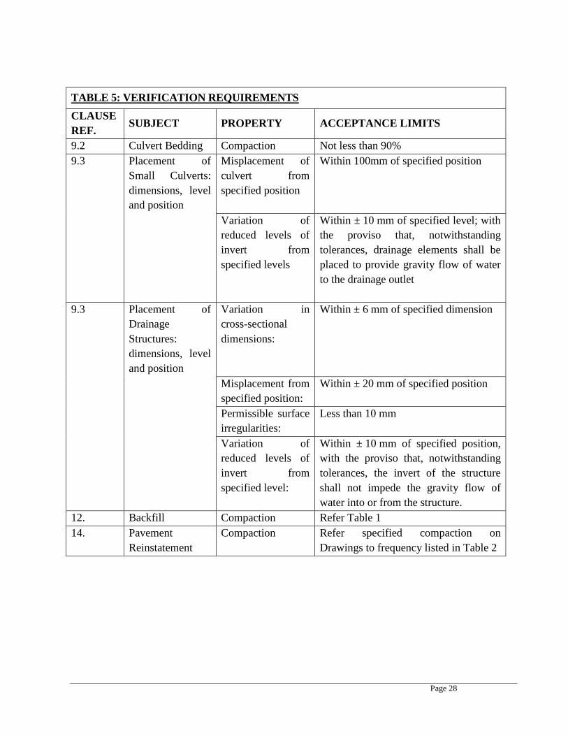
TABLE 5: VERIFICATION REQUIREMENTS CLAUSE REF. SUBJECT PROPERTY ACCEPTANCE LIMITS
9.2 Culvert Bedding Compaction Not less than 90% 9.3 Placement of
Small Culverts: dimensions, level and position
Misplacement of culvert from specified position
Within 100mm of specified position
Variation of reduced levels of invert from specified levels
Within ± 10 mm of specified level; with the proviso that, notwithstanding tolerances, drainage elements shall be placed to provide gravity flow of water to the drainage outlet
9.3 Placement of Drainage Structures: dimensions, level and position
Variation in cross-sectional dimensions:
Within ± 6 mm of specified dimension
Misplacement from specified position:
Within ± 20 mm of specified position
Permissible surface irregularities:
Less than 10 mm
Variation of reduced levels of invert from specified level:
Within ± 10 mm of specified position, with the proviso that, notwithstanding tolerances, the invert of the structure shall not impede the gravity flow of water into or from the structure.
12. Backfill Compaction Refer Table 1 14. Pavement
Reinstatement Compaction Refer specified compaction on
Drawings to frequency listed in Table 2
Page 29
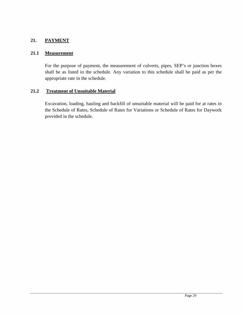
21. PAYMENT 21.1 Measurement
For the purpose of payment, the measurement of culverts, pipes, SEP’s or junction boxes shall be as listed in the schedule. Any variation to this schedule shall be paid as per the appropriate rate in the schedule.
21.2 Treatment of Unsuitable Material
Excavation, loading, hauling and backfill of unsuitable material will be paid for at rates in the Schedule of Rates, Schedule of Rates for Variations or Schedule of Rates for Daywork provided in the schedule.
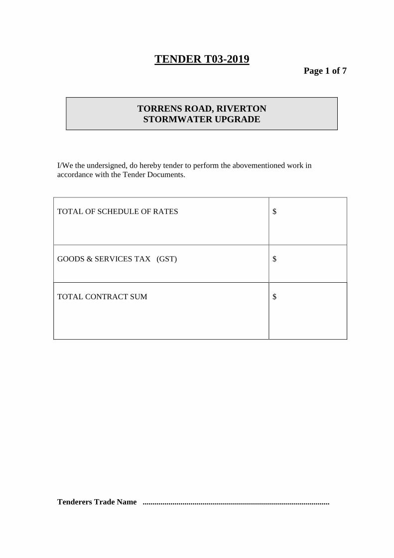
TENDER T03-2019
Page 1 of 7
TORRENS ROAD, RIVERTON
STORMWATER UPGRADE
I/We the undersigned, do hereby tender to perform the abovementioned work in accordance with the Tender Documents. TOTAL OF SCHEDULE OF RATES
$
GOODS & SERVICES TAX (GST)
$
TOTAL CONTRACT SUM
$
Tenderers Trade Name ..............................................................................................

TORRENS ROAD, RIVERTON STORMWATER UPGRADE
SCHEDULE 1-SCHEDULE OF RATES Page 2 of 7
Item Description of Work Unit Quantity Rate Amount
1 Preliminaries - Site establishment including setting out of works, ongoing traffic management and supervision
Item 1
2 Locating and depthing of services prior to construction Item 1
3 Delivery & disposal of existing kerbing, footpath, pipework & bitumen (disposal fees allowance)
tonnes 100
4
RUN 1 - FROM SEP 1 to SEP 2 - Trenching, Supply, installation and backfill of 2 x 375mm Box Culverts - Allow for Reinstatement of DPTI road crossing as per DPTI specification
m 13.63
5
RUN 2 - FROM SEP 2 to JB 1 - Trenching, Supply, installation and backfill of 1 x 450mm Box Culvert Allow for Reinstatement of Council Footpath and road to match in with existing
m 7.2
6
RUN 3 - FROM JB 1 to JB 2 - Trenching, Supply, installation and backfill of 1 x 450mm RCP - Allow for Reinstatement of Council road to match in with existing
m 51.1
7
RUN 4 - FROM JB 2 to JB 3 - Trenching, Supply, installation and backfill of 1 x 450mm RCP - Allow for Reinstatement of Council road to match in with existing
m 5.21
8
RUN 5 - FROM JB 3 to SEP 4 - Trenching, Supply, installation and backfill of 1 x 450mm Pipe - Can be Stormpro or BlacMax pipes as installation is in verge area - Allow for Reinstatement of Council road reserve to match in with existing
m 105.66
9
RUN 6 - FROM SEP 4 to JB 4 - Trenching, Supply, installation and backfill of 1 x 900 x 375 Box Culvert Allow for Reinstatement of Council Footpath and road to match in with existing
m 20.4
TORRENS ROAD, RIVERTON STORMWATER UPGRADE
SCHEDULE 1-SCHEDULE OF RATES Page 3 of 7
Item Description of Work Unit Quantity Rate Amount
10
RUN 7 - FROM JB 4 to JB5 - Trenching, Supply, installation and backfill of 1 x 600mm Pipe - Can be Stormpro or BlacMax pipes as installation is in verge area - Allow for Reinstatement of Council road reserve to match in with existing
m 85.63
11
RUN 8 - FROM JB 5 to SEP 5 - Trenching, Supply, installation and backfill of 1 x 600mm RCP - Allow for Reinstatement of Council road to match in with existing
m 7.69
12
RUN 9 - FROM SEP 5 to Outlet @ Open Drain - Trenching, Supply, installation and backfill of 1 x 600mmPipe - Can be Stormpro or BlacMax pipes as installation is in verge area - Allow for Reinstatement of Council road to match in with existing
m 50.24
13 RUN 10 - SWALE TYPE 1 Excavate swale and dispose of material within 10km of site lm 100
14 RUN 11 - SWALE TYPE 2 Excavate swale and dispose of material within 10km of site lm 40
15
RUN 12 - FROM SWALE TYPE 2 ACROSS RAILWAY TCE - Trenching, Supply, installation and backfill of 1 x 1200 x 300 Box Culvert Allow for Reinstatement of road to match in with existing
m 9.64
16 RUN 13 - SWALE TYPE 2 Excavate swale and dispose of material within 10km of site lm 40
17
Supply and installation of 1800 x 600 Side Entry Pit (SEP) Pits (As per size on drawings) , Surrounds and Lids as per DPTI Specifications
each 5
18 Supply and installation of Junction boxes - various sizes as per drawings each 5
TORRENS ROAD, RIVERTON STORMWATER UPGRADE
SCHEDULE 1-SCHEDULE OF RATES Page 4 of 7
Item Description of Work Unit Quantity Rate Amount
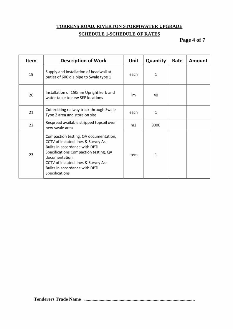
19 Supply and installation of headwall at outlet of 600 dia pipe to Swale type 1 each 1
20 Installation of 150mm Upright kerb and water table to new SEP locations lm 40
21 Cut existing railway track through Swale Type 2 area and store on site each 1
22 Respread available stripped topsoil over new swale area m2 8000
23
Compaction testing, QA documentation, CCTV of instated lines & Survey As- Builts in accordance with DPTI Specifications Compaction testing, QA documentation, CCTV of instated lines & Survey As- Builts in accordance with DPTI Specifications
Item 1
Tenderers Trade Name ..............................................................................................
STORMWATER DRAINAGE CONSTRUCTION
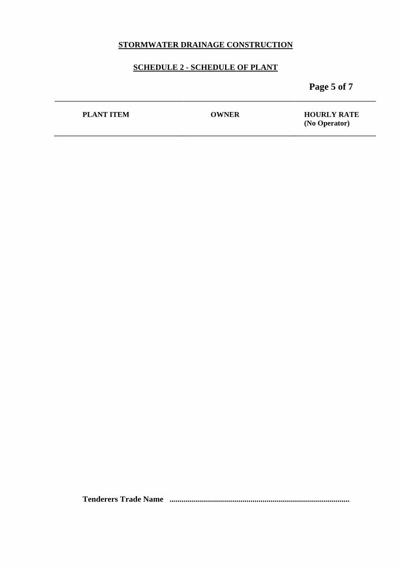
SCHEDULE 2 - SCHEDULE OF PLANT
Page 5 of 7
PLANT ITEM
OWNER
HOURLY RATE (No Operator)
Tenderers Trade Name .........................................................................................

STORMWATER DRAINAGE CONSTRUCTION
SCHEDULE 3 - SCHEDULE OF LABOUR
Page 6 of 7
CATEGORIES OF LABOUR
HOURLY RATE
1 Foreman 1 Backhoe Operator 1 Loader Operator 1 Drainlayer 1 Labourer 1 Truck Driver 1 Grader Operator 1 Excavator Operator Tenderers Trade Name ..............................................................................................

STORMWATER DRAINAGE CONSTRUCTION
SCHEDULE 4 - SCHEDULE OF SUB CONTRACTORS Page 7 of 7
SUB CONTRACTOR - Name & Address
PROPOSED SUB CONTRACT ELEMENT
Tenderers Trade Name ..............................................................................................