classic 300d perkins november, 2008 - lincoln · pdf file · 2014-08-04classic...
TRANSCRIPT

CLASSIC ® 300 D PERKINS
OPERATOR’S MANUAL
For Machines with Code Numbers 11110, 11111, 11248, 11249, 11280, 11281, 11411, 11412
November, 2008
Safety Depends on YouLincoln arc welding equipmentis designed and built with safetyin mind. However, your overallsafety can be increased byproper instal lat ion ... andthoughtful operation on yourpart. DO NOT INSTALL,OPERATE OR REPAIR THISEQUIPMENT WITHOUTREADING THIS MANUAL ANDTHE SAFETY PRECAUTIONSCONTAINED THROUGHOUT.And, most importantly, thinkbefore you act and be careful.
• Sales and Service through Subsidiaries and Distributors Worldwide •
Cleveland, Ohio 44117-1199 U.S.A. TEL: 216.481.8100 FAX: 216.486.1751 WEB SITE: www.lincolnelectric.com
• World's Leader in Welding and Cutting Products •
Copyright © Lincoln Global Inc.
IM842-C
FOR ENGINEpowered equipment.
1.a. Turn the engine off before troubleshooting and maintenancework unless the maintenance work requires it to be running.
____________________________________________________1.b. Operate engines in open, well-ventilated
areas or vent the engine exhaust fumesoutdoors.
____________________________________________________1.c. Do not add the fuel near an open flame
welding arc or when the engine is running.Stop the engine and allow it to cool beforerefueling to prevent spilled fuel from vaporiz-ing on contact with hot engine parts andigniting. Do not spill fuel when filling tank. Iffuel is spilled, wipe it up and do not startengine until fumes have been eliminated.
____________________________________________________1.d. Keep all equipment safety guards, covers and devices in
position and in good repair.Keep hands, hair, clothing andtools away from V-belts, gears, fans and all other movingparts when starting, operating or repairing equipment.
____________________________________________________
1.e. In some cases it may be necessary to remove safetyguards to perform required maintenance. Removeguards only when necessary and replace them when themaintenance requiring their removal is complete.Always use the greatest care when working near movingparts.
___________________________________________________1.f. Do not put your hands near the engine fan.
Do not attempt to override the governor oridler by pushing on the throttle control rodswhile the engine is running.
___________________________________________________1.g. To prevent accidentally starting gasoline engines while
turning the engine or welding generator during maintenancework, disconnect the spark plug wires, distributor cap ormagneto wire as appropriate.
iSAFETYi
ARC WELDING CAN BE HAZARDOUS. PROTECT YOURSELF AND OTHERS FROM POSSIBLE SERIOUS INJURY OR DEATH.KEEP CHILDREN AWAY. PACEMAKER WEARERS SHOULD CONSULT WITH THEIR DOCTOR BEFORE OPERATING.
Read and understand the following safety highlights. For additional safety information, it is strongly recommended that youpurchase a copy of “Safety in Welding & Cutting - ANSI Standard Z49.1” from the American Welding Society, P.O. Box351040, Miami, Florida 33135 or CSA Standard W117.2-1974. A Free copy of “Arc Welding Safety” booklet E205 is availablefrom the Lincoln Electric Company, 22801 St. Clair Avenue, Cleveland, Ohio 44117-1199.
BE SURE THAT ALL INSTALLATION, OPERATION, MAINTENANCE AND REPAIR PROCEDURES AREPERFORMED ONLY BY QUALIFIED INDIVIDUALS.
WARNING
Mar ʻ95
ELECTRIC ANDMAGNETIC FIELDSmay be dangerous
2.a. Electric current flowing through any conductor causeslocalized Electric and Magnetic Fields (EMF). Weldingcurrent creates EMF fields around welding cables andwelding machines
2.b. EMF fields may interfere with some pacemakers, andwelders having a pacemaker should consult their physicianbefore welding.
2.c. Exposure to EMF fields in welding may have other healtheffects which are now not known.
2.d. All welders should use the following procedures in order tominimize exposure to EMF fields from the welding circuit:
2.d.1. Route the electrode and work cables together - Securethem with tape when possible.
2.d.2. Never coil the electrode lead around your body.
2.d.3. Do not place your body between the electrode andwork cables. If the electrode cable is on your rightside, the work cable should also be on your right side.
2.d.4. Connect the work cable to the workpiece as close aspossible to the area being welded.
2.d.5. Do not work next to welding power source.
1.h. To avoid scalding, do not remove theradiator pressure cap when the engine ishot.
CALIFORNIA PROPOSITION 65 WARNINGS
Diesel engine exhaust and some of its constituentsare known to the State of California to cause can-cer, birth defects, and other reproductive harm.
The engine exhaust from this product containschemicals known to the State of California to causecancer, birth defects, or other reproductive harm.
The Above For Diesel Engines The Above For Gasoline Engines
iiSAFETYii
ARC RAYS can burn.4.a. Use a shield with the proper filter and cover
plates to protect your eyes from sparks andthe rays of the arc when welding or observingopen arc welding. Headshield and filter lensshould conform to ANSI Z87. I standards.
4.b. Use suitable clothing made from durable flame-resistantmaterial to protect your skin and that of your helpers fromthe arc rays.
4.c. Protect other nearby personnel with suitable, non-flammablescreening and/or warn them not to watch the arc nor exposethemselves to the arc rays or to hot spatter or metal.
ELECTRIC SHOCK cankill.3.a. The electrode and work (or ground) circuits
are electrically “hot” when the welder is on.Do not touch these “hot” parts with your bareskin or wet clothing. Wear dry, hole-free
gloves to insulate hands.
3.b. Insulate yourself from work and ground using dry insulation.Make certain the insulation is large enough to cover your fullarea of physical contact with work and ground.
In addition to the normal safety precautions, if weldingmust be performed under electrically hazardousconditions (in damp locations or while wearing wetclothing; on metal structures such as floors, gratings orscaffolds; when in cramped positions such as sitting,kneeling or lying, if there is a high risk of unavoidable oraccidental contact with the workpiece or ground) usethe following equipment:
• Semiautomatic DC Constant Voltage (Wire) Welder.• DC Manual (Stick) Welder.• AC Welder with Reduced Voltage Control.
3.c. In semiautomatic or automatic wire welding, the electrode,electrode reel, welding head, nozzle or semiautomaticwelding gun are also electrically “hot”.
3.d. Always be sure the work cable makes a good electricalconnection with the metal being welded. The connectionshould be as close as possible to the area being welded.
3.e. Ground the work or metal to be welded to a good electrical(earth) ground.
3.f. Maintain the electrode holder, work clamp, welding cable andwelding machine in good, safe operating condition. Replacedamaged insulation.
3.g. Never dip the electrode in water for cooling.
3.h. Never simultaneously touch electrically “hot” parts ofelectrode holders connected to two welders because voltagebetween the two can be the total of the open circuit voltageof both welders.
3.i. When working above floor level, use a safety belt to protectyourself from a fall should you get a shock.
3.j. Also see Items 6.c. and 8.
FUMES AND GASEScan be dangerous.5.a. Welding may produce fumes and gases
hazardous to health. Avoid breathing thesefumes and gases.When welding, keepyour head out of the fume. Use enoughventilation and/or exhaust at the arc to keep
fumes and gases away from the breathing zone. Whenwelding with electrodes which require specialventilation such as stainless or hard facing (seeinstructions on container or MSDS) or on lead orcadmium plated steel and other metals or coatingswhich produce highly toxic fumes, keep exposure aslow as possible and below Threshold Limit Values (TLV)using local exhaust or mechanical ventilation. Inconfined spaces or in some circumstances, outdoors, arespirator may be required. Additional precautions arealso required when welding on galvanized steel.
5. b. The operation of welding fume control equipment is affectedby various factors including proper use and positioning ofthe equipment, maintenance of the equipment and the spe-cific welding procedure and application involved. Workerexposure level should be checked upon installation andperiodically thereafter to be certain it is within applicableOSHA PEL and ACGIH TLV limits.
5.c. Do not weld in locations near chlorinated hydrocarbon vaporscoming from degreasing, cleaning or spraying operations.The heat and rays of the arc can react with solvent vapors toform phosgene, a highly toxic gas, and other irritating prod-ucts.
5.d. Shielding gases used for arc welding can displace air andcause injury or death. Always use enough ventilation,especially in confined areas, to insure breathing air is safe.
5.e. Read and understand the manufacturerʼs instructions for thisequipment and the consumables to be used, including thematerial safety data sheet (MSDS) and follow youremployerʼs safety practices. MSDS forms are available fromyour welding distributor or from the manufacturer.
5.f. Also see item 1.b.
AUG 06
iiiSAFETYiii
FOR ELECTRICALLYpowered equipment.
8.a. Turn off input power using the disconnectswitch at the fuse box before working onthe equipment.
8.b. Install equipment in accordance with the U.S. NationalElectrical Code, all local codes and the manufacturerʼsrecommendations.
8.c. Ground the equipment in accordance with the U.S. NationalElectrical Code and the manufacturerʼs recommendations.
CYLINDER may explodeif damaged.7.a. Use only compressed gas cylinders
containing the correct shielding gas for theprocess used and properly operatingregulators designed for the gas and
pressure used. All hoses, fittings, etc. should be suitable forthe application and maintained in good condition.
7.b. Always keep cylinders in an upright position securelychained to an undercarriage or fixed support.
7.c. Cylinders should be located:• Away from areas where they may be struck or subjected tophysical damage.
• A safe distance from arc welding or cutting operations andany other source of heat, sparks, or flame.
7.d. Never allow the electrode, electrode holder or any otherelectrically “hot” parts to touch a cylinder.
7.e. Keep your head and face away from the cylinder valve outletwhen opening the cylinder valve.
7.f. Valve protection caps should always be in place and handtight except when the cylinder is in use or connected foruse.
7.g. Read and follow the instructions on compressed gascylinders, associated equipment, and CGA publication P-l,“Precautions for Safe Handling of Compressed Gases inCylinders,” available from the Compressed Gas Association1235 Jefferson Davis Highway, Arlington, VA 22202.
Jan, 07
WELDING and CUTTINGSPARKS cancause fire or explosion.6.a. Remove fire hazards from the welding area.
If this is not possible, cover them to preventthe welding sparks from starting a fire.
Remember that welding sparks and hotmaterials from welding can easily go through small cracksand openings to adjacent areas. Avoid welding nearhydraulic lines. Have a fire extinguisher readily available.
6.b. Where compressed gases are to be used at the job site,special precautions should be used to prevent hazardoussituations. Refer to “Safety in Welding and Cutting” (ANSIStandard Z49.1) and the operating information for theequipment being used.
6.c. When not welding, make certain no part of the electrodecircuit is touching the work or ground. Accidental contactcan cause overheating and create a fire hazard.
6.d. Do not heat, cut or weld tanks, drums or containers until theproper steps have been taken to insure that such procedureswill not cause flammable or toxic vapors from substancesinside. They can cause an explosion even though they havebeen “cleaned”. For information, purchase “RecommendedSafe Practices for the Preparation for Welding and Cutting ofContainers and Piping That Have Held HazardousSubstances”, AWS F4.1 from the American Welding Society(see address above).
6.e. Vent hollow castings or containers before heating, cutting orwelding. They may explode.
6.f. Sparks and spatter are thrown from the welding arc. Wear oilfree protective garments such as leather gloves, heavy shirt,cuffless trousers, high shoes and a cap over your hair. Wearear plugs when welding out of position or in confined places.Always wear safety glasses with side shields when in awelding area.
6.g. Connect the work cable to the work as close to the weldingarea as practical. Work cables connected to the buildingframework or other locations away from the welding areaincrease the possibility of the welding current passingthrough lifting chains, crane cables or other alternate cir-cuits. This can create fire hazards or overheat lifting chainsor cables until they fail.
6.h. Also see item 1.c.
6.I. Read and follow NFPA 51B “ Standard for Fire PreventionDuring Welding, Cutting and Other Hot Work”, availablefrom NFPA, 1 Batterymarch Park,PO box 9101, Quincy, Ma022690-9101.
6.j. Do not use a welding power source for pipe thawing.
ivSAFETYiv
Mar. ʻ93
PRÉCAUTIONS DE SÛRETÉPour votre propre protection lire et observer toutes les instructionset les précautions de sûreté specifiques qui parraissent dans cemanuel aussi bien que les précautions de sûreté générales suiv-antes:
Sûreté Pour Soudage A LʼArc1. Protegez-vous contre la secousse électrique:
a. Les circuits à lʼélectrode et à la piéce sont sous tensionquand la machine à souder est en marche. Eviter toujourstout contact entre les parties sous tension et la peau nueou les vétements mouillés. Porter des gants secs et sanstrous pour isoler les mains.
b. Faire trés attention de bien sʼisoler de la masse quand onsoude dans des endroits humides, ou sur un planchermetallique ou des grilles metalliques, principalement dansles positions assis ou couché pour lesquelles une grandepartie du corps peut être en contact avec la masse.
c. Maintenir le porte-électrode, la pince de masse, le câblede soudage et la machine à souder en bon et sûr étatdefonctionnement.
d.Ne jamais plonger le porte-électrode dans lʼeau pour lerefroidir.
e. Ne jamais toucher simultanément les parties sous tensiondes porte-électrodes connectés à deux machines à souderparce que la tension entre les deux pinces peut être letotal de la tension à vide des deux machines.
f. Si on utilise la machine à souder comme une source decourant pour soudage semi-automatique, ces precautionspour le porte-électrode sʼapplicuent aussi au pistolet desoudage.
2. Dans le cas de travail au dessus du niveau du sol, se protégercontre les chutes dans le cas ou on recoit un choc. Ne jamaisenrouler le câble-électrode autour de nʼimporte quelle partiedu corps.
3. Un coup dʼarc peut être plus sévère quʼun coup de soliel,donc:
a. Utiliser un bon masque avec un verre filtrant appropriéainsi quʼun verre blanc afin de se protéger les yeux du ray-onnement de lʼarc et des projections quand on soude ouquand on regarde lʼarc.
b. Porter des vêtements convenables afin de protéger lapeau de soudeur et des aides contre le rayonnement delʻarc.
c. Protéger lʼautre personnel travaillant à proximité ausoudage à lʼaide dʼécrans appropriés et non-inflammables.
4. Des gouttes de laitier en fusion sont émises de lʼarc desoudage. Se protéger avec des vêtements de protection libresde lʼhuile, tels que les gants en cuir, chemise épaisse, pan-talons sans revers, et chaussures montantes.
5. Toujours porter des lunettes de sécurité dans la zone desoudage. Utiliser des lunettes avec écrans lateraux dans leszones où lʼon pique le laitier.
6. Eloigner les matériaux inflammables ou les recouvrir afin deprévenir tout risque dʼincendie dû aux étincelles.
7. Quand on ne soude pas, poser la pince à une endroit isolé dela masse. Un court-circuit accidental peut provoquer unéchauffement et un risque dʼincendie.
8. Sʼassurer que la masse est connectée le plus prés possiblede la zone de travail quʼil est pratique de le faire. Si on placela masse sur la charpente de la construction ou dʼautresendroits éloignés de la zone de travail, on augmente le risquede voir passer le courant de soudage par les chaines de lev-age, câbles de grue, ou autres circuits. Cela peut provoquerdes risques dʼincendie ou dʼechauffement des chaines et descâbles jusquʼà ce quʼils se rompent.
9. Assurer une ventilation suffisante dans la zone de soudage.Ceci est particuliérement important pour le soudage de tôlesgalvanisées plombées, ou cadmiées ou tout autre métal quiproduit des fumeés toxiques.
10. Ne pas souder en présence de vapeurs de chlore provenantdʼopérations de dégraissage, nettoyage ou pistolage. Lachaleur ou les rayons de lʼarc peuvent réagir avec les vapeursdu solvant pour produire du phosgéne (gas fortement toxique)ou autres produits irritants.
11. Pour obtenir de plus amples renseignements sur la sûreté,voir le code “Code for safety in welding and cutting” CSAStandard W 117.2-1974.
PRÉCAUTIONS DE SÛRETÉ POURLES MACHINES À SOUDER ÀTRANSFORMATEUR ET ÀREDRESSEUR
1. Relier à la terre le chassis du poste conformement au code delʼélectricité et aux recommendations du fabricant. Le dispositifde montage ou la piece à souder doit être branché à unebonne mise à la terre.
2. Autant que possible, Iʼinstallation et lʼentretien du poste seronteffectués par un électricien qualifié.
3. Avant de faires des travaux à lʼinterieur de poste, la debranch-er à lʼinterrupteur à la boite de fusibles.
4. Garder tous les couvercles et dispositifs de sûreté à leurplace.
vv
Thank You for selecting a QUALITY product by Lincoln Electric. We want youto take pride in operating this Lincoln Electric Company product••• as much pride as we have in bringing this product to you!
Read this Operators Manual completely before attempting to use this equipment. Save this manual and keep ithandy for quick reference. Pay particular attention to the safety instructions we have provided for your protection.The level of seriousness to be applied to each is explained below:
WARNINGThis statement appears where the information must be followed exactly to avoid serious personal injury or loss of life.
This statement appears where the information must be followed to avoid minor personal injury or damage to this equipment.
CAUTION
Please Examine Carton and Equipment For Damage ImmediatelyWhen this equipment is shipped, title passes to the purchaser upon receipt by the carrier. Consequently, Claimsfor material damaged in shipment must be made by the purchaser against the transportation company at thetime the shipment is received.
Please record your equipment identification information below for future reference. This information can befound on your machine nameplate.
Product _________________________________________________________________________________
Model Number ___________________________________________________________________________
Code Number or Date Code_________________________________________________________________
Serial Number____________________________________________________________________________
Date Purchased___________________________________________________________________________
Where Purchased_________________________________________________________________________
Whenever you request replacement parts or information on this equipment, always supply the information youhave recorded above. The code number is especially important when identifying the correct replacement parts.
On-Line Product Registration- Register your machine with Lincoln Electric either via fax or over the Internet.
• For faxing: Complete the form on the back of the warranty statement included in the literature packetaccompanying this machine and fax the form per the instructions printed on it.
• For On-Line Registration: Go to our WEB SITE at www.lincolnelectric.com. Choose “Quick Links” and then“Product Registration”. Please complete the form and submit your registration.
CUSTOMER ASSISTANCE POLICYThe business of The Lincoln Electric Company is manufacturing and selling high quality welding equipment, consumables, and cutting equip-ment. Our challenge is to meet the needs of our customers and to exceed their expectations. On occasion, purchasers may ask LincolnElectric for advice or information about their use of our products. We respond to our customers based on the best information in our posses-sion at that time. Lincoln Electric is not in a position to warrant or guarantee such advice, and assumes no liability, with respect to such infor-mation or advice. We expressly disclaim any warranty of any kind, including any warranty of fitness for any customerʼs particular purpose,with respect to such information or advice. As a matter of practical consideration, we also cannot assume any responsibility for updating orcorrecting any such information or advice once it has been given, nor does the provision of information or advice create, expand or alter anywarranty with respect to the sale of our products.
Lincoln Electric is a responsive manufacturer, but the selection and use of specific products sold by Lincoln Electric is solely within the controlof, and remains the sole responsibility of the customer. Many variables beyond the control of Lincoln Electric affect the results obtained inapplying these types of fabrication methods and service requirements.
Subject to Change – This information is accurate to the best of our knowledge at the time of printing. Please refer to www.lincolnelectric.comfor any updated information.

vi vi TABLE OF CONTENTS
Page
Installation .......................................................................................................Section ATechnical Specifications ........................................................................................A-1General Description ...............................................................................................A-2Design Features ....................................................................................................A-2Pre-Operation Installation ......................................................................................A-3
Safety Precautions ..........................................................................................A-3Exhaust Spark Arrester ...................................................................................A-3Location/Ventilation.........................................................................................A-3Machine Grounding.........................................................................................A-3Lift Bail ............................................................................................................A-3Trailers ............................................................................................................A-3Vehicle Mounting.............................................................................................A-4Polarity Control and Cable Sizes ....................................................................A-4
Pre-Operation Service ...........................................................................................A-4Oil ....................................................................................................................A-4Fuel .................................................................................................................A-4Cooling System ...............................................................................................A-4Battery Charging .............................................................................................A-5
Operation .........................................................................................................Section BEngine Operation...................................................................................................B-1
Starting The Perkins 404C-22 Engine.............................................................B-1High Altitude Operation ...................................................................................B-1Stopping the engine, Engine Break-In......................................................B-1,B-2
Welder Operation...................................................................................................B-2Duty Cycle.......................................................................................................B-2Control of Welding Current..............................................................................B-2Idler Operation ................................................................................................B-3Auxiliary Power, Fuel Consumption Data........................................................B-3
Accessories .....................................................................................................Section COptional Features (Field Installed)..................................................................C-1,C-2
Maintenance ....................................................................................................Section DSafety Precautions ................................................................................................D-1General Instructions ..............................................................................................D-1Cooling System .....................................................................................................D-1Bearings ................................................................................................................D-1Commutator and Brushes .....................................................................................D-1Idler Maintenance..................................................................................................D-2Nameplates ...........................................................................................................D-2Purging Air from Fuel System................................................................................D-2Engine Service Chart ....................................................................................D-3, D-4GFCI Receptacle Testing and Resetting Procedure .............................................D-5
Troubleshooting ..............................................................................................Section ESafety Precautions.................................................................................................E-1Welder Troubleshooting ........................................................................................E-2Electronic Idler Troubleshooting Guide..........................................................E-3, E-4Engine Troubleshooting Guide ..............................................................E-5, E-6, E-7
Diagrams ..........................................................................................................Section FWiring Diagrams......................................................................................F-1, F-2. F-3Dimension Print......................................................................................................F-4
Parts List.................................................................................................................P-507

A-1INSTALLATION
CLASSIC® 300D PERKINS
A-1
TECHNICAL SPECIFICATIONS - CLASSIC® 300D PERKINS
Make/Model Description Speed (RPM) Displacement Starting CapacitiesSystem
4 Cylinder 135.6 cu. in 12VDC battery Fuel: 15 gal.4 Cycle (2.2 ltrs) (Group 24, 650 57 L.
Naturally Aspirated High Idle 1800 cold crank amps)Water-Cooled Low Idle 1400 Bore x Stroke 2.0 KW Starter Oil: 8.45 Qts.
Perkins Diesel Engine Full Load 1725 55 A. Alternator 8 L.404C-22 Cast Iron Cylinder, 3.43” x 3.64” w/ built in reg.
Block/Crankcase 32.7HP @1800 RPM (For Codes 11111 Coolant: 9.5 Qts.and Below) 9.0 L.65 A. Alternatorw/ built in reg.(For Codes 11248and Above)
INPUT - DIESEL ENGINE
RATED OUTPUT @ 104°F(40°C) - WELDER
MODEL HEIGHT WIDTH DEPTH WEIGHT
K1643-3 CSAw/o Wire Feed Module 1354 lbs. (Codes 11110, 11248, 45.5 in. 24.00 in. 65.0 in. (616 kg)
11280, 11411) (1156 mm) (610 mm) (1651 mmK1643-4 CSA
w/ Wire Feed Module 1389lbs. (Codes 11111, 11249, (630 kg)
11281, 11412)
RATED OUTPUT @ 104°F(40°C) - GENERATOR
DESCRIPTION RATED DC OUTPUT * Duty DC CURRENT RANGEVOLTS @ RATED AMPS CYCLE Fine Adjustments in each Range
40-350 Amps220-Max.
300 Amp DC Welder 30V @ 250A 100% 160-240All Copper Windings 32V @ 300A 60% 120-190
Pure DC Power Generator 99V DC Max. OCV @ 1800RPM 80-130Min.-90
Auxiliary Power (1)
3,000 Watts Continuous, 60 Hz AC26 Amps @ 115V13 Amps @ 230V
PHYSICAL DIMENSIONS (2)
* Based on a 10 min. period.
(1) Output rating in watts is equivalent to volt-amperes at unity power factor. Output voltage is within ± 10% at all loads up torated capacity. When welding, available auxiliary power will be reduced.
(2) Height to top of exhaust elbow.
A-2INSTALLATION
CLASSIC® 300D PERKINS
A-2
GENERAL DESCRIPTION
The Classic® 300D Perkins is a heavy duty, enginedriven, DC arc welding power source, capable of pro-viding constant current output for stick welding or DCTIG welding. This welder is wound with all coppercoils, rated at 300 amps/32 Volts, and provides otherClassic® features such as improved door latches andstainless hinges. With the addition of the optional
K623-1 Wire Feed Module™, the Classic® 300DPerkins will provide constant voltage output for run-ning the LN-7, LN-23P, or LN-25 wire feeders. (TheWire Feed Module is factory installed on the K1643-4). The optional K924-5 Remote Control Kit, providesa remote control rheostat for remote fine current andopen circuit voltage adjustment. See Section C fordescription.
The Classic® 300D Perkins has an Electronic EngineProtection System. In the event of sudden low oilpressure or high coolant temperature, the engineimmediately shuts down. The Classic® 300D Perkinshas a current range of 40-350 DC amps with outputratings as follows:
These units are also capable of providing 3 KVA of115/230 volts of 60 cycle AC auxiliary power.
The Classic® 300D Perkins uses the Perkins 404C-22industrial water-cooled diesel engine.
DESIGN FEATURES
Control Panel
Both the engine and the welder controls are locatedon one recessed panel at the exciter end of themachine. The welder controls consist of a five step“Current Range Selector” switch and a “Fine CurrentAdjustment” rheostat. The welder is equipped with a“Start” button, an “Ignition” switch, an “Idler” controlswitch, and a “Glow Plug” button for easier coldweather starting.
The control panel also contains an engine tempera-ture gauge, a battery charging ammeter, an oil pres-sure gauge, for auxiliary power one three pronggrounding type receptacles, one GFCI receptacle andcircuit breakers for protection.
All Copper Windings - For long life and dependableoperation.
Engine Idler - The Classic® 300D Perkins isequipped with an electronic automatic engine idler. Itautomatically increases and decreases engine speedwhen starting and stopping welding or using aux-iliary power. A built-in time delay permits changingelectrodes before the engine slows to its low idlespeed. The “Idler” control switch on the panel locksthe idler in high idle position when desired.
Auxiliary Power - 3.0 KVA of nominal 115/230V,60Hz, AC. Output voltage is maintained within ± 10%at all loads up to rated capacity. (See OptionalFeatures Section C for Power Plug Kit.)
GFCI Receptacle - One UL approved 115V groundfault circuit interrupter duplex type receptacle is stan-dard. See the MAINTENANCE section for detailedinformation on testing and resetting the GFCI recepta-cle.
Welder Enclosure - The complete welder is rubbermounted on a rugged steel “C” channel base.
The output terminals are placed at the side of themachines so that they are protected by the door. Theoutput terminals are labeled (+) and (-).
Cranking System - A 12 volt electric starter is stan-dard.
Air Cleaner - Heavy duty two stage dry type.
Muffler - A muffler and stainless steel exhaust outletelbow are standard.
Engine Hour Meter - A meter to record hours of oper-ation.
Engine Protection - The system shuts the enginedown in the event of sudden low oil pressure or highcoolant temperature. A warning light on the controlpanel will indicate such a fault. To reset the engine forrestarting, turn the ignition switch off then on.
Oil Drain Valve - A ball valve, hose and clamp arestandard.
Remote Control - The Remote / Local Switch andReceptacle are standard.
250A @ 30V300A @ 32V
100%60%
RATED OUTPUT DUTY CYCLE
A-3INSTALLATION
CLASSIC® 300D PERKINS
A-3
PRE-OPERATION INSTALLATION
EXHAUST SPARK ARRESTERSome federal, state or local laws may require thatengines be equipped with exhaust spark arresterswhen they are operated in certain locations whereunarrested sparks may present a fire hazard. Thestandard muffler included with this welder does notqualify as a spark arrester. When required by localregulations, a suitable spark arrester must be installedand properly maintained.
Use of an incorrect arrester may lead to engine damageor performance loss. Contact the engine manufacturerfor specific recommendations.------------------------------------------------------------------------LOCATION / VENTILATION
Always operate the welder with the doors closed.Leaving the doors open changes the designed air flowand may cause overheating.
The welder should be located to provide an unrestrict-ed flow of clean, cool air. Also, locate the welder sothat engine exhaust fumes are properly vented to anoutside area.
MACHINE GROUNDINGAccording to the United States National ElectricalCode, the frame of this portable generator is notrequired to be grounded and is permitted to serve asthe grounding means for cord connected equipmentplugged into its receptacle.
Some state, local, or other codes or unusual operatingcircumstances may require the machine frame to begrounded. It is recommended that you determine theextent to which such requirements may apply to yourparticular situation and follow them explicitly. Amachine grounding stud marked with the symbol isprovided on the welding generator frame foot. In gen-eral, if the machine is to be grounded, it should beconnected with a #8 or larger copper wire to a solidearth ground such as a metal water pipe going intothe ground for at least ten feet and having no insulat-ed joints, or to the metal framework of a buildingwhich has been effectively grounded. The U.S.National Code lists a number of alternate means ofgrounding electrical equipment.
LIFT BAILA lift bail is provided for lifting with a hoist.
TRAILER (SEE OPTIONAL FEATURES) If the user adapts a non-Lincoln trailer, he must assumeresponsibility that the method of attachment and usagedoes not result in a safety hazard nor damage the weld-ing equipment. Some of the factors to be considered areas follows:1. Design capacity of trailer vs. weight of Lincoln equip-
ment and likely additional attachments.
Do not attempt to use this equipment until youhave thoroughly read the engine manufacturerʼsmanual supplied with your welder. It includesimportant safety precautions, detailed enginestarting, operating and maintenance instructions,and parts lists.------------------------------------------------------------------------
ELECTRIC SHOCK can kill.• Do not touch electrically live parts or
electrode with skin or wet clothing.• Insulate yourself from work and
ground• Always wear dry insulating gloves.
------------------------------------------------------------------------ENGINE EXHAUST can kill.• Use in open, well ventilated areas or
vent exhaust outside.
------------------------------------------------------------------------MOVING PARTS can injure.• Do not operate with doors open or
guards off.• Stop engine before servicing.• Keep away from moving parts.
------------------------------------------------------------------------See additional warning information at thefront of this operatorʼs manual.
-----------------------------------------------------------
WARNING
CAUTION
• Lift only with equipment of adequatelifting capacity.
• Be sure machine is stable when lifting.• Do not lift this machine using lift bail if
it is equipped with a heavy accessorysuch as trailer or gas cylinder.
FALLING • Do not lift machine if lift bail is
EQUIPMENT can damaged.
cause injury. • Do not operate machine while
suspended from lift bail.
----------------------------------------------------------------------------
WARNING
DO NOT MOUNT OVER COMBUSTIBLE SUR-FACES.Where there is a combustible surface directly under sta-tionary or fixed electrical equipment, the surface shallbe covered with a steel plate at least .06”(1.6mm) thick,which shall extend not more than 5.90”(150mm) beyondthe equipment on all sides. --------------------------------------------------------------------------------
CAUTION
PRE-OPERATION SERVICE
READ the engine operating and maintenance instruc-tions supplied with this machine.
OIL
This unit is supplied from the factory with the enginecrankcase filled with a high quality SAE 10W/30 oil.This oil should be acceptable for most typical ambienttemperatures. Consult the engine operation manualfor specific engine manufacturerʼs recommendations.Upon receipt of the welder, check the engine dipstickto be sure the oil is at the “full” mark. DO NOT overfill.
FUEL
Fill the fuel tank with the grade of fuel recommendedin the Engine Operatorʼs manual. Make sure the fuelvalve on the water separator is in the open position.
COOLING SYSTEM
The radiator has been filled at the factory with a 50-50mixture of ethylene glycol antifreeze and water.Check the radiator level and add a 50-50 solution asneeded (see engine manual or antifreeze container foralternate antifreeze recommendations).
CAUTION
A-4INSTALLATION
CLASSIC® 300D PERKINS
A-4
2. Proper support of, and attachment to, the base ofthe welding equipment so there will be no unduestress to the framework.
3. Proper placement of the equipment on the trailer toensure stability side to side and front to back whenbeing moved and when standing by itself whilebeing operated or serviced.
4. Typical conditions of use, i.e., travel speed, rough-ness of surface on which the trailer will be operat-ed; environmental conditions, likely maintenance.
5. Conformance with federal, state and local laws. (1)(1) Consult your federal, state and local laws regarding specificrequirements for use on public highways.
POLARITY CONTROL AND CABLE SIZES
With the engine off, route the electrode and workcables through the strain relief bracket on the baseand connect to the studs located below the fuel tankmounting rail. (See size recommendations below.)For positive polarity, connect the electrode cable tothe terminal marked “+”. For Negative polarity, con-nect the electrode cable to the “-” stud. These con-nections should be checked periodically and tightenedif necessary.
When welding at a considerable distance from thewelder, be sure you use ample sized welding cables.
RECOMMENDED COPPER CABLE SIZESCables Sizes for Combined Lengthof Electrode Plus Work Cable
Amps Duty Cycle Up to 200ft.(61m) 200 to 250ft.(61 to 76m)
250 100% 1 1/0
300 60% 1/0 2/0
VEHICLE MOUNTING
Improperly mounted concentrated loads maycause unstable vehicle handling and tires or othercomponents to fail.• Only transport this Equipment on serviceable
vehicles which are rated and designed for suchloads.
• Distribute, balance and secure loads so vehicleis stable under conditions of use.
• Do not exceed maximum rated loads for compo-nents such as suspension, axles and tires.
• Use appropriate nuts bolts and lockwashers toattach the equipment base to the metal bed orframe of vehicle.
• Follow vehicle manufacturerʼs instructions.------------------------------------------------------------------------
WARNING
• Stop engine while fueling.• Do not smoke when fueling.• Keep sparks and flame away
from tank.• Do not leave unattended while
fueling.• Wipe up spilled fuel and allow
fumes to clear before startingengine.
• Do not overfill tank, fuel expan-sion may cause overflow.
DIESEL FUEL ONLY------------------------------------------------------------------------
WARNING
DIESEL FUELcan
cause fire
A-5INSTALLATION
CLASSIC® 300D PERKINS
A-5
BATTERY CHARGING
The Classic® 300D Perkins is equipped with a wetcharged battery. The charging current is automatical-ly regulated when the battery is low (after starting theengine) to a trickle current when the battery is fullycharged.
When replacing, jumping or otherwise connecting thebattery to the battery cables, the proper polarity mustbe observed. This system is NEGATIVE GROUND.
GASES FROM BATTERY can explode.• Keep sparks, flame and cigarettesaway.
BATTERY ACID can burn eyes andskin.• Wear gloves and eye protection andbe careful when boosting, charging orworking near battery.
To prevent EXPLOSION when:a) Installing a new battery - disconnect the
negative cable from the old battery first and connect the negative cable to the new battery last.
b) Connecting a battery charger - remove the battery from the welder by disconnecting the negative cable first, then the positive cable and battery clamp. When reinstalling, connect the negative cable last.
c) Using a booster - connect the positive lead to the battery first, then connect the negative lead to the ground lead on the base.
To prevent ELECTRICAL DAMAGE when:a) Installing a new battery.b) Using a booster.
Use correct polarity - Negative Ground.
To prevent BATTERY DISCHARGE, if you have an ignition switch, turn it off when engine is notrunning.
• To prevent BATTERY BUCKLING, tighten nuts on battery clamp until snug.
------------------------------------------------------------------------
WARNING
B-1OPERATIONB-1
ENGINE OPERATION
Operate the welder with the doors closed. Leavingthe doors open changes the designed air flow and cancause overheating.
STARTING THE CLASSIC® 300D PERKINS404C-22 DIESEL ENGINE
1. Turn the “IDLER” switch to “HIGH”.2. Turn the “IGNITION” switch to “ON”.3. Press the Glow Plug button for 20 to 30 seconds.
(maximum 60 seconds).4. Press the Start button. When the engine starts
running, release both buttons. If the engine fails tostart in 20 seconds, wait 30 seconds and repeatthe above procedure.
5. Observe the oil pressure. If no pressure showswithin 30 seconds, stop the engine and consultthe engine operating manual. To stop the engine,turn the “IGNITION” switch to “OFF”.
6. If the engine protection warning light comes onduring cranking or after start up, the “IGNITION”switch must be turned “OFF” to reset the engineprotection system.
CLASSIC® 300D PERKINS
Do not attempt to use this equipment until youhave thoroughly read the engine manufacturerʼsmanual supplied with your welder. It includesimportant safety precautions, detailed enginestarting, operating and maintenance instructions,and parts lists.------------------------------------------------------------------------
ELECTRIC SHOCK can kill.• Do not touch electrically live parts or
electrode with skin or wet clothing.• Insulate yourself from work and
ground• Always wear dry insulating gloves.
------------------------------------------------------------------------ENGINE EXHAUST can kill.• Use in open, well ventilated areas or
vent exhaust outside.
------------------------------------------------------------------------MOVING PARTS can injure.• Do not operate with doors open or
guards off.• Stop engine before servicing.• Keep away from moving parts.
------------------------------------------------------------------------
See additional warning information at thefront of this operatorʼs manual.
------------------------------------------------------------
WARNING
7. Allow the engine to run at high idle speed for sev-eral minutes to warm the engine. Stop the engineand recheck the oil level, after allowing sufficienttime for the oil to drain into the pan. If the level isdown, fill it to the full mark again. The engine con-trols were properly set at the factory and shouldrequire no adjusting when received.
COLD WEATHER STARTING:
With a fully charged battery and the proper weight oil,the engine should start satisfactorily even down toabout -15°F (-26°C), it maybe desirable to install cold-starting aides.
Note: Extreme cold weather staring may requirelonger glow plug operation.
Under NO conditions should ether or otherstarting fluids be used!------------------------------------------------------------------------HIGH ALTITUDE OPERATION:
The engine will run correctly up to an altitude of 600m(2000ft.). If the engine is to be operated permanentlyat an altitude above this, the fuel consumption andexhaust emissions may be excessive.
Contact the Perkins Application Department for anyengine adjustments that may be required.
STOPPING THE ENGINE
1. Turn the “IGNITION” switch to “OFF”
At the end of each dayʼs welding, check the crankcaseoil level, drain accumulated dirt and water from thewater separator located on the fuel rail. Refill the fueltank to minimize moisture condensation in the tank.Also, running out of fuel tends to draw dirt into the fuelsystem.
When hauling the welder between job sites, close thefuel feed valve on the separator located on the fuelrail.
If the fuel supply is cut off or runs out while the fuelpump is operating, air may be entrapped in the fueldistribution system. If this happens, bleeding of thefuel system may be necessary. Use qualified person-nel to do this per the instructions in the MAINTE-NANCE section of this manual.
WARNING
B-2OPERATIONB-2
CLASSIC® 300D PERKINS
ENGINE BREAK-IN
Lincoln Electric selects high quality, heavy-duty industrialengines for the portable welding machines we offer.While it is normal to see a small amount of crankcase oilconsumption during initial operation, excessive oil use,wet stacking (oil or tar like substance at the exhaustport), or excessive smoke is not normal.
Larger machines with a capacity of 350 amperes andhigher, which are operated at low or no-load conditionsfor extended periods of time are especially susceptible tothe conditions described above. To accomplish success-ful engine break-in, most diesel-powered equipmentneeds only to be run at a reasonably heavy load withinthe rating of the welder for some period of time duringthe engineʼs early life. However, if the welder is subject-ed to extensive light loading, occasional moderate toheavy loading of the engine may sometimes be neces-sary. Caution must be observed in correctly loading adiesel/generator unit.
1. Connect the welder output studs to a suitable resis-tive load bank. Note that any attempt to short theoutput studs by connecting the welding leads togeth-er, direct shorting of the output studs, or connectingthe output leads to a length of steel will result in cat-astrophic damage to the generator and voids thewarranty.
2. Set the welder controls for an output current andvoltage within the welder rating and duty cycle. Notethat any attempt to exceed the welder rating or dutycycle for any period of time will result in catastrophicdamage to the generator and voids the warranty.
3. Periodically shut off the engine and check thecrankcase oil level.
WELDER OPERATION
DUTY CYCLE
The NEMA output rating of the Classic® 300D Perkins is300 amperes at 32 arc volts on a 60% duty cycle (consultSpecifications in this manual for alternate ratings). Dutycycle is based on a ten minute period; thus, the welder canbe loaded at rated output for six minutes out of every tenminute period.
CONTROL OF WELDING CURRENT
DO NOT TURN THE “CURRENT RANGE SELECTOR”WHILE WELDING because the current may arc betweenthe contacts and damage the switch.-------------------------------------------------------------------------------The “Current Range Selector” provides five overlapping cur-rent ranges. The “Fine Current Adjustment” adjusts the cur-rent from minimum to maximum within each range. Opencircuit voltage is also controlled by the “Fine CurrentAdjustment” permitting control of the arc characteristics.
A high open circuit voltage setting provides the soft “butter-ing” arc with best resistance to pop-outs preferred for mostwelding. To get this characteristic, set the “Current RangeSelector” to the lowest setting that still provides the currentyou need and set the “Fine Current Adjustment” near maxi-mum.
For example: to obtain 175 amps and a soft arc, set the“Current Range Selector” to the 190-120 position and thenadjust the “Fine Current Adjustment” for 175 amps.
When a forceful “digging” arc is required, usually for verticaland overhead welding, use a higher “Current RangeSelector” setting and lower open circuit voltage.
For example: to obtain 175 amps and a forceful arc, set the“Current Range Selector” to the 240-160 position and the“Fine Current Adjustment” setting to get 175 amps.
Some arc instability may be experienced with EXX10 elec-trodes when trying to operate with long arc techniques atsettings at the lower end of the open circuit voltage range.
DO NOT attempt to set the “Current Range Selector” betweenthe five points designated on the nameplate.--------------------------------------------------------------------------------
These switches have a spring loaded cam which almosteliminates the possibility of setting this switch between thedesignated points.
ELECTRIC SHOCK can kill.• Do not touch electrically live parts or
electrode with skin or wet clothing.• Insulate yourself from work and ground.
FUMES & GASES can be dangerous.• Keep your head out of the fumes.• Use ventilation or exhaust to remove
fumes from breathing zone.
WELDING SPARKS can cause fire orexplosion.• Keep flammable material away.
WARNING
ARC RAYS can burn.• Wear eye, ear, and body protection.
CAUTION
CAUTION
B-3OPERATIONB-3
AUXILIARY POWER
If a GFCI receptacle is tripped, See the MAINTE-NANCE section for detailed information on testing andresetting the GFCI receptacle.
The AC auxiliary power, supplied as a standard, has arating of 3.0 KVA of 115/230 VAC (60 hertz).
With the 3.0 KVA, 115/230 VAC auxiliary power, one115V GFCI and one 230V duplex, grounding typereceptacles are provided. The circuit is protected withcircuit breakers.
The rating of 3.0 KVA permits a maximum continuouscurrent of 13 amps to be drawn from the 230 voltduplex receptacle. Or a total of 20 amps can be drawnfrom the 115 volt GFCI receptacle. The total combinedload of all receptacles is not to exceed 3.0 KVA.
An optional power plug kit is available. When this kit isspecified, the customer is supplied with a plug foreach receptacle.
CLASSIC® 300D PERKINS
IDLER OPERATION
Start the engine with the “Idler” switch in the “High”position. Allow it to run at high idle speed for severalminutes to warm the engine. See Specifications foroperating speeds.
The idler is controlled by the “Idler” toggle switch onthe welder control panel. The switch has two posi-tions as follows:
1. In the “High” position, the idler solenoiddeactivates, and the engine goes to high idlespeed. The speed is controlled by the governor.
2. In the “Auto” / position, the idler oper-ates as follows:
a. When welding or drawing power for lights or tools(approximately 100 watts minimum) from thereceptacles, the idler solenoid deactivates andthe engine operates at high idle speed.
b. When welding ceases or the power load is turnedoff, a preset time delay of about 15 secondsstarts. This time delay cannot be adjusted.
c. If the welding or power load is not re-startedbefore the end of the time delay, the idler sole-noid activates and reduces the engine to low idlespeed.
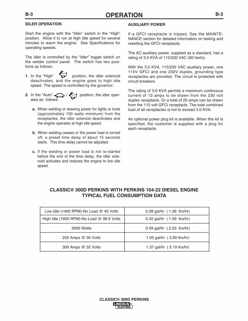
CLASSIC® 300D PERKINS WITH PERKINS 104-22 DIESEL ENGINETYPICAL FUEL CONSUMPTION DATA
Low Idle (1400 RPM)-No Load @ 45 Volts
High Idle (1800 RPM)-No Load @ 96.6 Volts
3000 Watts
250 Amps @ 30 Volts
300 Amps @ 32 Volts
0.28 gal/hr ( 1.06 ltrs/hr)
0.42 gal/hr ( 1.59 ltrs/hr)
0.59 gal/hr ( 2.23 ltrs/hr)
1.03 gal/hr ( 3.90 ltrs/hr)
1.37 gal/hr ( 5.19 ltrs/hr)
C-1ACCESSORIESC-1
CLASSIC® 300D PERKINS
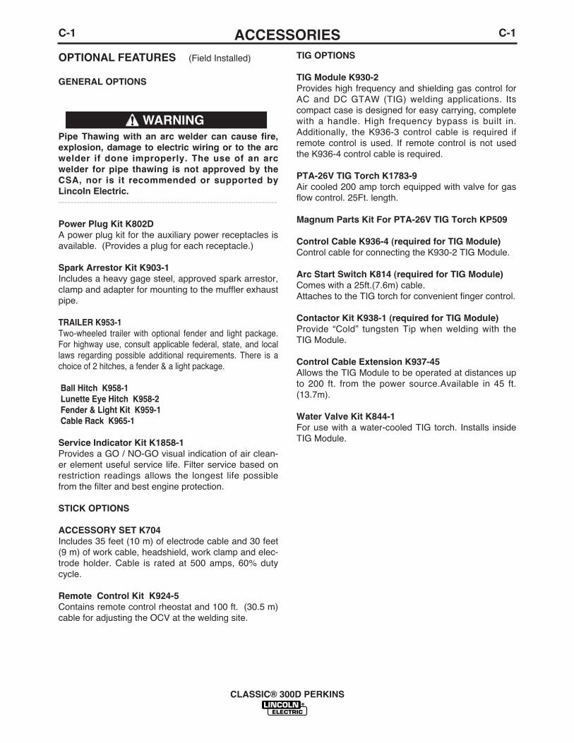
OPTIONAL FEATURES (Field Installed)
GENERAL OPTIONS
Pipe Thawing with an arc welder can cause fire,explosion, damage to electric wiring or to the arcwelder if done improperly. The use of an arcwelder for pipe thawing is not approved by theCSA, nor is it recommended or supported byLincoln Electric.------------------------------------------------------------------------
Power Plug Kit K802D A power plug kit for the auxiliary power receptacles isavailable. (Provides a plug for each receptacle.)
Spark Arrestor Kit K903-1Includes a heavy gage steel, approved spark arrestor,clamp and adapter for mounting to the muffler exhaustpipe.
TRAILER K953-1Two-wheeled trailer with optional fender and light package.For highway use, consult applicable federal, state, and locallaws regarding possible additional requirements. There is achoice of 2 hitches, a fender & a light package.
Ball Hitch K958-1Lunette Eye Hitch K958-2 Fender & Light Kit K959-1Cable Rack K965-1
Service Indicator Kit K1858-1Provides a GO / NO-GO visual indication of air clean-er element useful service life. Filter service based onrestriction readings allows the longest life possiblefrom the filter and best engine protection.
STICK OPTIONS
ACCESSORY SET K704Includes 35 feet (10 m) of electrode cable and 30 feet(9 m) of work cable, headshield, work clamp and elec-trode holder. Cable is rated at 500 amps, 60% dutycycle.
Remote Control Kit K924-5 Contains remote control rheostat and 100 ft. (30.5 m)cable for adjusting the OCV at the welding site.
TIG OPTIONS
TIG Module K930-2Provides high frequency and shielding gas control forAC and DC GTAW (TIG) welding applications. Itscompact case is designed for easy carrying, completewith a handle. High frequency bypass is built in.Additionally, the K936-3 control cable is required ifremote control is used. If remote control is not usedthe K936-4 control cable is required.
PTA-26V TIG Torch K1783-9Air cooled 200 amp torch equipped with valve for gasflow control. 25Ft. length.
Magnum Parts Kit For PTA-26V TIG Torch KP509
Control Cable K936-4 (required for TIG Module)Control cable for connecting the K930-2 TIG Module.
Arc Start Switch K814 (required for TIG Module)Comes with a 25ft.(7.6m) cable.Attaches to the TIG torch for convenient finger control.
Contactor Kit K938-1 (required for TIG Module)Provide “Cold” tungsten Tip when welding with theTIG Module.
Control Cable Extension K937-45Allows the TIG Module to be operated at distances upto 200 ft. from the power source.Available in 45 ft.(13.7m).
Water Valve Kit K844-1For use with a water-cooled TIG torch. Installs insideTIG Module.
WARNING

C-2ACCESSORIESC-2
WIRE FEEDER OPTIONS
Wire Feed Module K623-1Provides constant voltage (CV) output with improvedarc stability for Innershield welding. Excellent for MIGwelding. Recommended wire feeders are the LN-7,LN-23P and LN-25. (Factory installed on the K1643-2).
LN-25 Wire Feeder K449
Portable CC/CV unit for flux-cored and MIG welding.Includes Gas Solenoid & Internal Contactor. RequiresWire Feed Module.
Remote Voltage Control Kit for LN-25 K444-2
Provides 25 ft. (7.5m) of remote output voltage controland output jumper (2 and 4) for machines having 14pin MS-type connector.
Magnum® 350 Innershield Gun for LN-25 K126-2For self-shielded wire with 15 ft. (4.5m) cable. For.062-3/32” (1.6-2.8mm) wire.
Magnum® 300 MIG Gun for LN-25 K1802-1
With 15 ft. (4.5m) cable. For .035”-.045” (0.9-1.2mm)gas shielded (Includes Connector Kit).
LN-23P Wire Feeder K316L-1
Portable CV unit for Innershield pipe welding. Controlcable operates contactor inside Wire Feed Module for“cold” electrode. Requires LN-23P Adapter Kit (K350-1) and Gun and Cable Assembly.
LN-23P Adapter Kit K350-1
Required to adapt LN-23P to any Lincoln powersource. Makes 14 pin connection at power source.
Magnum® 250 Innershield Gun for LN-23P K355-10
For lighter weight and easier handling. Rated 250amps, 60% duty cycle. For .068 through 5/64” (1.7through 2.0 mm) Innershield wire and includesreduced speed switch. For pipewelding, an M1147662° gun tube is recommended.
62° gun tube for PipeWelding KP1909-1
Recommended modification for K355-X or K345-xguns with 90° gun tubes. Compatible with K126-1,-2,K264-8 and K355-10.
Magnum Spool Gun K487-25
Hand held semiautomatic wire feeder requires SGControl Module. 25 ft. length.
SG Control Module K488 (For Magnum Spool Gun)
The interface between the power source and thespool gun. Provides control of wire speed and gasflow.
Input Cable K691-10 ( For SG Control Module)
For Lincoln engine drives with 14-pin MS-type con-nection, separate 115V NEMA receptacle and output stud connections. 10 ft. length.
CLASSIC® 300D PERKINS
D-1MAINTENANCED-1
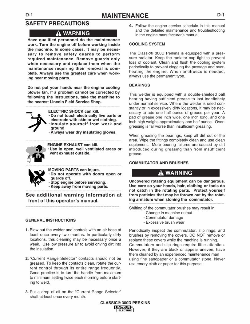
SAFETY PRECAUTIONS
GENERAL INSTRUCTIONS
1. Blow out the welder and controls with an air hose atleast once every two months. In particularly dirtylocations, this cleaning may be necessary once aweek. Use low pressure air to avoid driving dirt intothe insulation.
2. “Current Range Selector” contacts should not begreased. To keep the contacts clean, rotate the cur-rent control through its entire range frequently.Good practice is to turn the handle from maximumto minimum setting twice each morning before start-ing to weld.
3. Put a drop of oil on the “Current Range Selector”shaft at least once every month.
4. Follow the engine service schedule in this manualand the detailed maintenance and troubleshootingin the engine manufacturerʼs manual.
COOLING SYSTEM
The Classic® 300D Perkins is equipped with a pres-sure radiator. Keep the radiator cap tight to preventloss of coolant. Clean and flush the cooling systemperiodically to prevent clogging the passage and over-heating the engine. When antifreeze is needed,always use the permanent type.
BEARINGS
This welder is equipped with a double-shielded ballbearing having sufficient grease to last indefinitelyunder normal service. Where the welder is used con-stantly or in excessively dirty locations, it may be nec-essary to add one half ounce of grease per year. Apad of grease one inch wide, one inch long, and oneinch high weighs approximately one half ounce. Over-greasing is far worse than insufficient greasing.
When greasing the bearings, keep all dirt out of thearea. Wipe the fittings completely clean and use cleanequipment. More bearing failures are caused by dirtintroduced during greasing than from insufficientgrease.
COMMUTATOR AND BRUSHES
Uncovered rotating equipment can be dangerous.Use care so your hands, hair, clothing or tools donot catch in the rotating parts. Protect yourselffrom particles that may be thrown out by the rotat-ing armature when stoning the commutator.------------------------------------------------------------------------Shifting of the commutator brushes may result in:
- Change in machine output- Commutator damage- Excessive brush wear
Periodically inspect the commutator, slip rings, andbrushes by removing the covers. DO NOT remove orreplace these covers while the machine is running.Commutators and slip rings require little attention.However, if they are black or appear uneven, havethem cleaned by an experienced maintenance man using fine sandpaper or a commutator stone. Neveruse emery cloth or paper for this purpose.
CLASSIC® 300D PERKINS
Have qualified personnel do the maintenancework. Turn the engine off before working insidethe machine. In some cases, it may be neces-sary to remove safety guards to performrequired maintenance. Remove guards onlywhen necessary and replace them when themaintenance requiring their removal is com-plete. Always use the greatest care when work-ing near moving parts.
Do not put your hands near the engine coolingblower fan. If a problem cannot be corrected byfollowing the instructions, take the machine tothe nearest Lincoln Field Service Shop.
-----------------------------------------------------------------------ELECTRIC SHOCK can kill.• Do not touch electrically live parts or
electrode with skin or wet clothing.• Insulate yourself from work and
ground• Always wear dry insulating gloves.
------------------------------------------------------------------------ENGINE EXHAUST can kill.• Use in open, well ventilated areas or
vent exhaust outside.
------------------------------------------------------------------------MOVING PARTS can injure.• Do not operate with doors open or
guards off.• Stop engine before servicing.• Keep away from moving parts.
------------------------------------------------------------------------See additional warning information atfront of this operatorʼs manual.
-----------------------------------------------------------
WARNING
WARNING

D-2MAINTENANCED-2
Replace brushes when they wear within 1/4” of thepigtail. A complete set of replacement brushes shouldbe kept on hand. Lincoln brushes have a curved faceto fit the commutator. Have an experienced mainte-nance man seat these brushes by lightly stoning thecommutator as the armature rotates at full speed untilcontact is made across the full face of the brushes.After stoning, blow out the dust with low pressure air.
To seat slip ring brushes, position the brushes inplace. Then slide one end of a piece of fine sandpaperbetween slip rings and brushes with the coarse sideagainst the brushes. With slight additional finger pres-sure on top of the brushes, pull the sandpaper aroundthe circumference of the rings - in direction of rotationonly - until brushes seat properly. In addition, stoneslip ring with a fine stone. Brushes must be seated100%.
Arcing or excessive exciter brush wear indicates apossible misaligned shaft. Have an authorized FieldService Shop check and realign the shaft.
IDLER MAINTENANCE
Before doing electrical work on the idler printedcircuit board, disconnect the battery.------------------------------------------------------------------------When installing a new battery or using a jumper bat-tery to start the engine, be sure the battery polarity isconnected properly. The correct polarity is negativeground. Damage to the engine alternator and theprinted circuit board can result from incorrect connec-tion.
1. Proper operation of the idler requires good ground-ing of the printed circuit board, reed switch, andbattery.
2. Idler solenoid is activated for low idle.
3. If desired, the welder can be used without automat-ic idling by setting the “Idler” switch to the “High”position.
NAMEPLATES
Whenever routine maintenance is performed on thismachine - or at least yearly - inspect all nameplatesand labels for legibility. Replace those which are nolonger clear. Refer to the parts list for the replace-ment item number.
PURGING AIR FROM FUEL SYSTEM(PERKINS 404C-22 ENGINE)
Keep fuel clear of open flames or arcs, allowengine to cool before working on the fuel system.Wipe up any spilled fuel and do not start engineuntil fumes clear.------------------------------------------------------------------------If the engine is running rough and you suspect air hasbeen trapped in the fuel system, (e.g. the engine wasallowed to run out of fuel) perform the following stepsusing qualified personnel:
1. Loosen by two or three turns, the vent screw(Figure D.1) on the fuel inlet connection.
FIGURE D.1
2. Operate the electric fuel pump by turning the“Ignition” switch “ON” until fuel, free of air, flowsfrom the vent point. Tighten the vent screw.
3. Contact your Perkins Engine repair facility if prob-lems persist.
CLASSIC® 300D PERKINS
CAUTION
WARNING
Vent Screw
PrimingLever
D-3MAINTENANCED-3
CLASSIC® 300D PERKINS
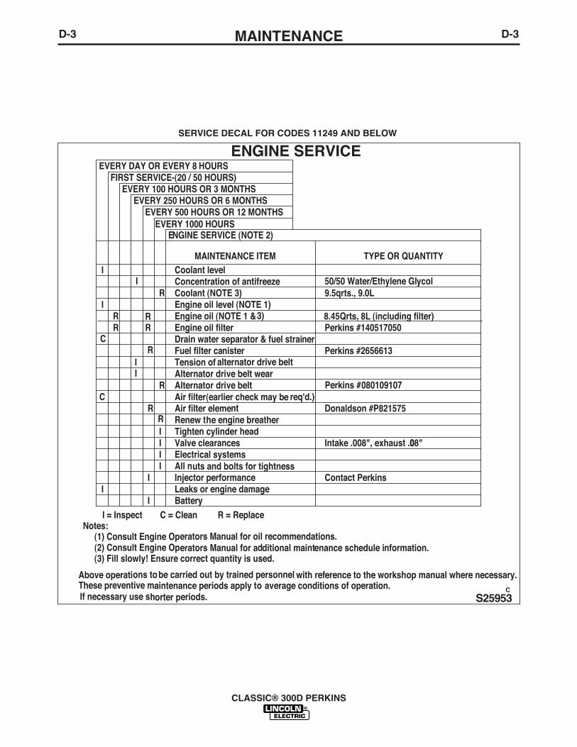
I
EVERY 500 HOURS OR 12 MONTHSEVERY 250 HOURS OR 6 MONTHS
EVERY 100 HOURS OR 3 MONTHSFIRST SERVICE-(20 / 50 HOURS)
EVERY DAY OR EVERY 8 HOURS
Perkins #140517050
If necessary use shorter periods.These preventive maintenance periods apply to average conditions of operation.
Perkins #2656613
TYPE OR QUANTITY
Above operations to be carried out by trained personnel with reference to the workshop manual where necessary.
9.5qrts., 9.0L
(3) Fill slowly! Ensure correct quantity is used.
8.45Qrts, 8L (including filter)
(2) Consult Engine Operators Manual for additional maintenance schedule information.(1) Consult Engine Operators Manual for oil recommendations.
Notes:
Alternator drive beltAlternator drive belt wear
R
Tension of alternator drive beltFuel filter canister
I
Drain water separator & fuel strainer
Engine oil (NOTE 1 & 3)
R
Engine oil level (NOTE 1)Coolant (NOTE 3)
MAINTENANCE ITEM
Concentration of antifreeze
I
R
Coolant level
RC
RR
I
R
ENGINE SERVICE
I
EVERY 1000 HOURS
Contact Perkins
Intake .008", exhaust .008"
Donaldson #P821575
R = ReplaceC = CleanBatteryLeaks or engine damage
I
Injector performanceAll nuts and bolts for tightness
I = Inspect
Electrical systems
II
Valve clearancesI
Tighten cylinder head
I
I
Renew the engine breatherI
Air filter elementAir filter (earlier check may be req'd.)
RC
Engine oil filter
ENGINE SERVICE (NOTE 2)
50/50 Water/Ethylene Glycol
Perkins #080109107
R
S25953C
SERVICE DECAL FOR CODES 11249 AND BELOW
D-4MAINTENANCED-4
CLASSIC® 300D PERKINS
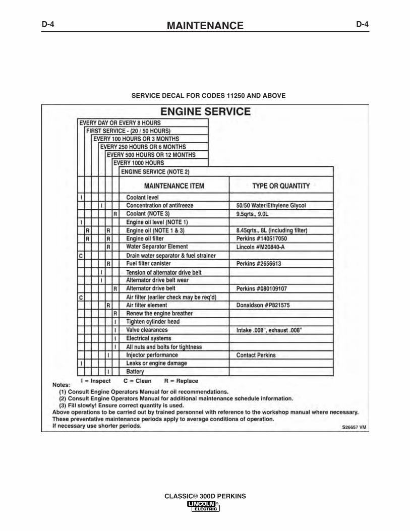
SERVICE DECAL FOR CODES 11250 AND ABOVE
D-5MAINTENANCED-5
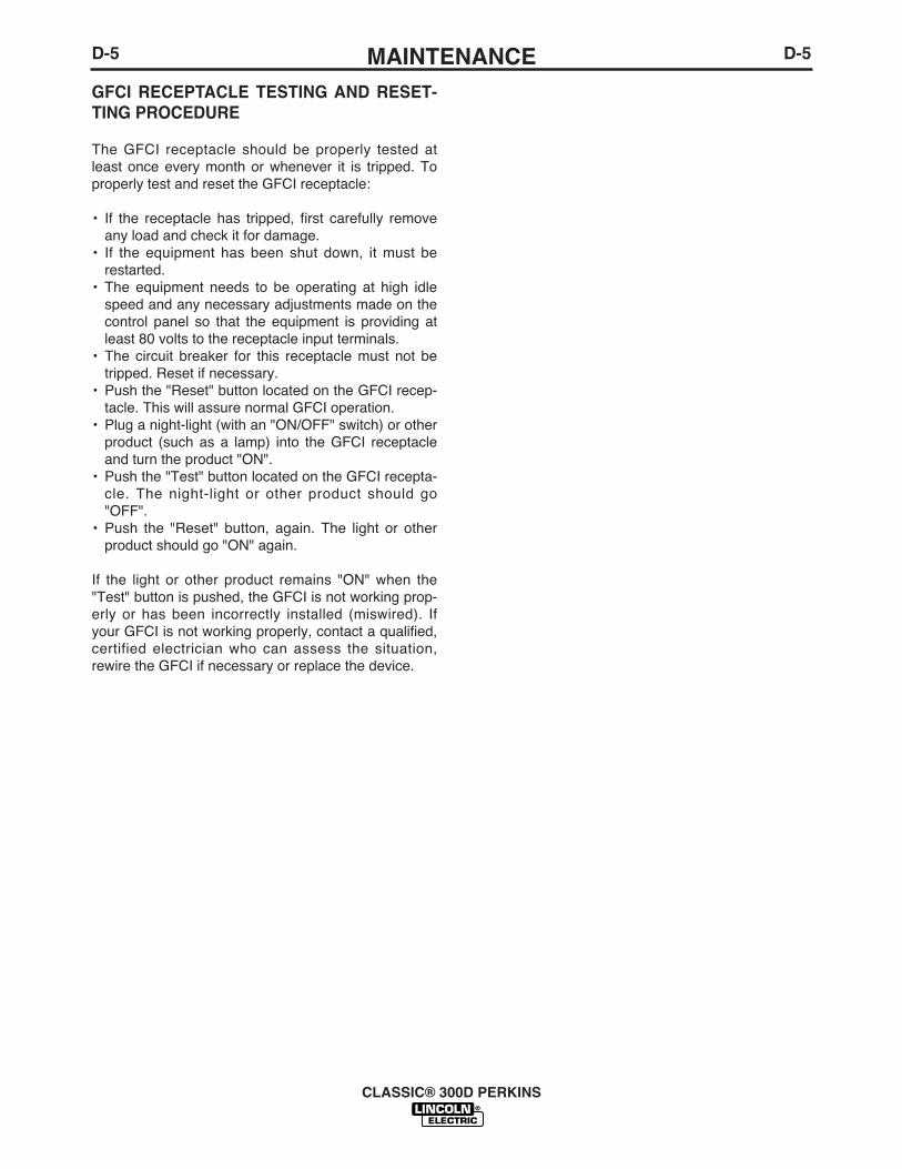
GFCI RECEPTACLE TESTING AND RESET-TING PROCEDURE
The GFCI receptacle should be properly tested atleast once every month or whenever it is tripped. Toproperly test and reset the GFCI receptacle:
• If the receptacle has tripped, first carefully removeany load and check it for damage.
• If the equipment has been shut down, it must berestarted.
• The equipment needs to be operating at high idlespeed and any necessary adjustments made on thecontrol panel so that the equipment is providing atleast 80 volts to the receptacle input terminals.
• The circuit breaker for this receptacle must not betripped. Reset if necessary.
• Push the "Reset" button located on the GFCI recep-tacle. This will assure normal GFCI operation.
• Plug a night-light (with an "ON/OFF" switch) or otherproduct (such as a lamp) into the GFCI receptacleand turn the product "ON".
• Push the "Test" button located on the GFCI recepta-cle. The night-light or other product should go"OFF".
• Push the "Reset" button, again. The light or otherproduct should go "ON" again.
If the light or other product remains "ON" when the"Test" button is pushed, the GFCI is not working prop-erly or has been incorrectly installed (miswired). Ifyour GFCI is not working properly, contact a qualified,certified electrician who can assess the situation,rewire the GFCI if necessary or replace the device.
CLASSIC® 300D PERKINS
E-1TROUBLESHOOTING
CLASSIC® 300D PERKINS
E-1
If for any reason you do not understand the test procedures or are unable to perform the tests/repairs safely, contact yourLocal Lincoln Authorized Field Service Facility for technical troubleshooting assistance before you proceed.
CAUTION
Have qualified personnel do the troubleshootingwork. Turn the engine off before working insidethe machine. In some cases, it may be neces-sary to remove safety guards to performrequired maintenance. Remove guards onlywhen necessary and replace them when themaintenance requiring their removal is com-plete. Always use the greatest care when work-ing near moving parts.
Do not put your hands near the engine coolingblower fan. If a problem cannot be corrected byfollowing the instructions, take the machine tothe nearest Lincoln Field Service Shop.
------------------------------------------------------------
WARNING
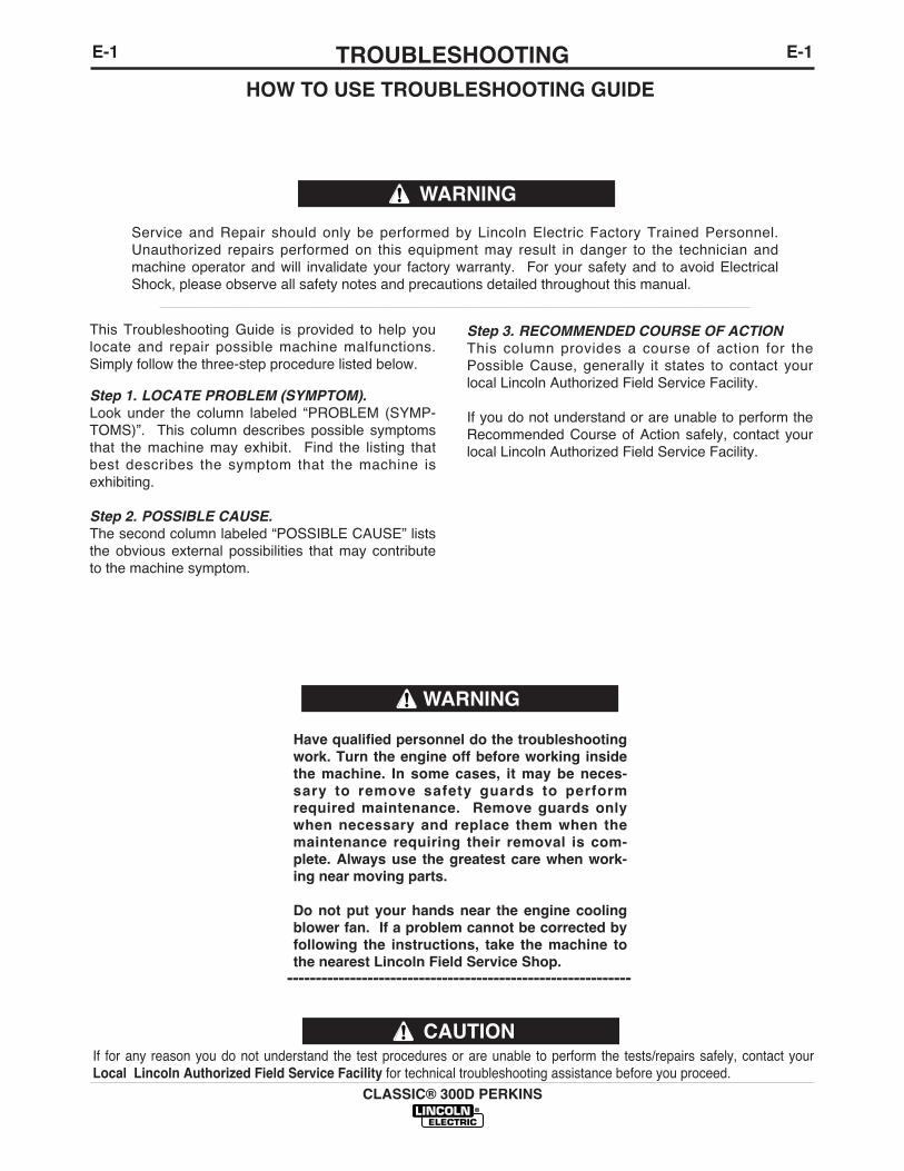
This Troubleshooting Guide is provided to help youlocate and repair possible machine malfunctions.Simply follow the three-step procedure listed below.
Step 1. LOCATE PROBLEM (SYMPTOM).Look under the column labeled “PROBLEM (SYMP-TOMS)”. This column describes possible symptomsthat the machine may exhibit. Find the listing thatbest describes the symptom that the machine isexhibiting.
Step 2. POSSIBLE CAUSE.The second column labeled “POSSIBLE CAUSE” liststhe obvious external possibilities that may contributeto the machine symptom.
Step 3. RECOMMENDED COURSE OF ACTIONThis column provides a course of action for thePossible Cause, generally it states to contact yourlocal Lincoln Authorized Field Service Facility.
If you do not understand or are unable to perform theRecommended Course of Action safely, contact yourlocal Lincoln Authorized Field Service Facility.
HOW TO USE TROUBLESHOOTING GUIDE
Service and Repair should only be performed by Lincoln Electric Factory Trained Personnel.Unauthorized repairs performed on this equipment may result in danger to the technician andmachine operator and will invalidate your factory warranty. For your safety and to avoid ElectricalShock, please observe all safety notes and precautions detailed throughout this manual.
__________________________________________________________________________
WARNING

CLASSIC® 300D PERKINS
E-2TROUBLESHOOTINGE-2Observe all Safety Guidelines detailed throughout this manual
If for any reason you do not understand the test procedures or are unable to perform the tests/repairs safely, contact yourLocal Lincoln Authorized Field Service Facility for technical troubleshooting assistance before you proceed.
CAUTION
PROBLEMS(SYMPTOMS)
POSSIBLE CAUSE
RECOMMENDEDCOURSE OF ACTION
Machine fails to hold the output(heat) consistently.
Welder starts but fails to generatecurrent.
Welding arc is loud and spattersexcessively.
Welding current too great or toosmall compared to indication onthe dial.
Arc continuously pops out.
1. Rough or dirty commutator.
2. Brushes may be worn down toLimit.
3. Field circuit may have variableresistance connection or inter-mittent open circuit due toloose connection or brokenwire.
4. Electrode lead or work leadconnection may be poor.
5. Wrong grade of brushes mayhave been installed on gener-ator.
6. Field rheostat may be makingpoor contact and overheating.
1. Generator or exciter brushesmay be loose or missing.
2. Exciter may not be operating.
3. Field circuit of generator orexciter may be open.
4. Exciter may have lost excita-tion.
5. Series field and armature cir-cuit may be open-circuited.
1. Current setting may be toohigh.
2. Polarity may be wrong.
1. Exciter output low causing lowoutput compared to dial indica-tion.
2. Operating speed too low or toohigh.
1. “Current Range Selector”switch may be set at an inter-mediate position.
If all recommended possible areasof misadjustment have beenchecked and the problem persists,Contact your local LincolnAuthorized Field Service Facility.
E-3TROUBLESHOOTING
CLASSIC® 300D PERKINS
E-3
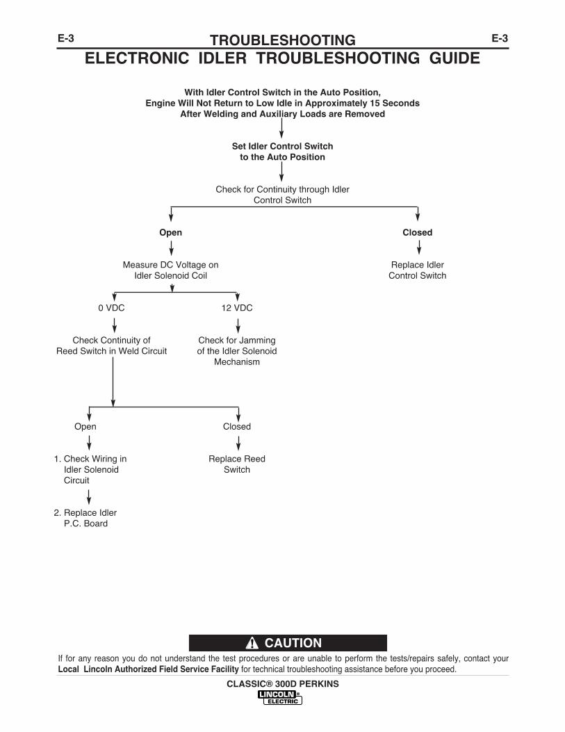
ELECTRONIC IDLER TROUBLESHOOTING GUIDE
With Idler Control Switch in the Auto Position,Engine Will Not Return to Low Idle in Approximately 15 Seconds
After Welding and Auxiliary Loads are Removed
Set Idler Control Switchto the Auto Position
Check for Continuity through IdlerControl Switch
Open Closed
Measure DC Voltage on Replace IdlerIdler Solenoid Coil Control Switch
0 VDC 12 VDC
Check Continuity of Check for JammingReed Switch in Weld Circuit of the Idler Solenoid
Mechanism
Open Closed
1. Check Wiring in Replace ReedIdler Solenoid SwitchCircuit
2. Replace IdlerP.C. Board
If for any reason you do not understand the test procedures or are unable to perform the tests/repairs safely, contact yourLocal Lincoln Authorized Field Service Facility for technical troubleshooting assistance before you proceed.
CAUTION
E-4TROUBLESHOOTING
CLASSIC® 300D PERKINS
E-4
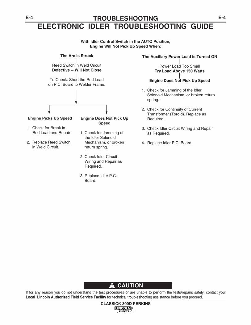
ELECTRONIC IDLER TROUBLESHOOTING GUIDE
With Idler Control Switch in the AUTO Position,Engine Will Not Pick Up Speed When:
The Arc is Struck
Reed Switch in Weld CircuitDefective -- Will Not Close
To Check: Short the Red Leadon P.C. Board to Welder Frame.
The Auxiliary Power Load is Turned ON
Power Load Too Small Try Load Above 150 Watts
Engine Does Not Pick Up Speed
1. Check for Jamming of the IdlerSolenoid Mechanism, or broken returnspring.
2. Check for Continuity of CurrentTransformer (Toroid). Replace asRequired.
3. Check Idler Circuit Wiring and Repairas Required.
4. Replace Idler P.C. Board.
Engine Picks Up Speed
1. Check for Break inRed Lead and Repair
2. Replace Reed Switchin Weld Circuit.
Engine Does Not Pick UpSpeed
1. Check for Jamming ofthe Idler SolenoidMechanism, or brokenreturn spring.
2. Check Idler CircuitWiring and Repair asRequired.
3. Replace Idler P.C.Board.
If for any reason you do not understand the test procedures or are unable to perform the tests/repairs safely, contact yourLocal Lincoln Authorized Field Service Facility for technical troubleshooting assistance before you proceed.
CAUTION

E-5TROUBLESHOOTING
CLASSIC® 300D PERKINS
E-5
If for any reason you do not understand the test procedures or are unable to perform the tests/repairs safely, contact yourLocal Lincoln Authorized Field Service Facility for technical troubleshooting assistance before you proceed.
CAUTION
Observe all Safety Guidelines detailed throughout this manual
PROBLEMS(SYMPTOMS)
POSSIBLE CAUSE
RECOMMENDEDCOURSE OF ACTION
Engine does not start.
Engine does not turn over.
Irregular running of the engine.
Engine stops during operation andthe Engine Protection light doesnot turn on.
1. Lack of fuel.
2. Air mixed in the fuel system.
3. Clogged fuel filter.
4. Irregular and faulty fuel supply(Injector pump trouble).
5. Glow plug not heated.
6. Clogged air cleaner.
7. No compression.
8. Engine protection light is ON.
1. Faulty Ignition switch and orInjector pump solenoid.
2. Insufficient charging or com-plete discharge of the battery.
3. Improper viscosity of the lubri-cating oil.
1. Air mixed in the fuel system.
2. Uneven fuel injection (Faultyfuel injector pump).
3. Clogged fuel filter.
4. Defective governor.
5. Engine itself defective.
1. Lack of fuel in the fuel tank.
2. Clogged fuel filter.
3. Air mixed in the fuel system.
4. Faulty function of the engine.
If all recommended possible areasof misadjustment have beenchecked and the problem persists,Contact your local LincolnAuthorized Field Service Facility.
E-6TROUBLESHOOTINGE-6
CLASSIC® 300D PERKINS
Observe all Safety Guidelines detailed throughout this manual
If for any reason you do not understand the test procedures or are unable to perform the tests/repairs safely, contact yourLocal Lincoln Authorized Field Service Facility for technical troubleshooting assistance before you proceed.
CAUTION
PROBLEMS(SYMPTOMS)
POSSIBLE CAUSE
RECOMMENDEDCOURSE OF ACTION
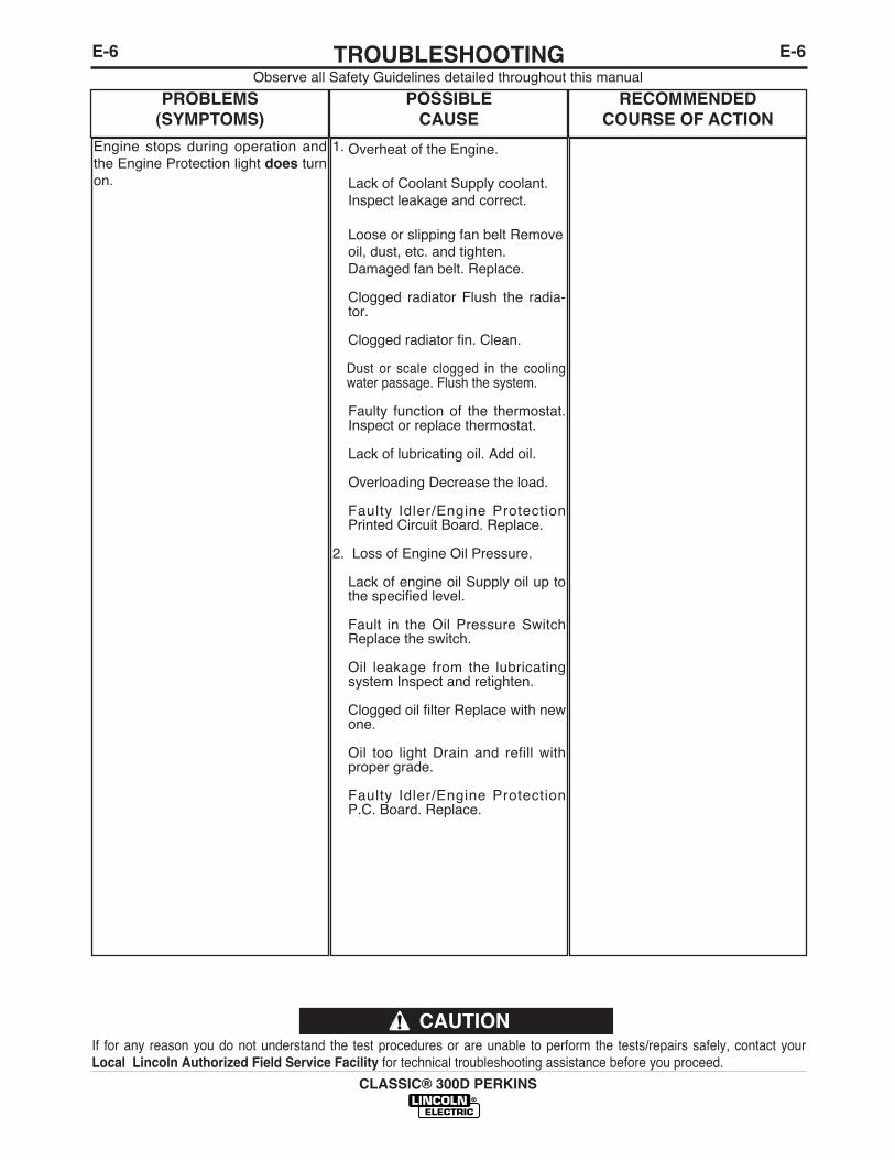
Engine stops during operation andthe Engine Protection light does turnon.
1. Overheat of the Engine.
Lack of Coolant Supply coolant.Inspect leakage and correct.
Loose or slipping fan belt Removeoil, dust, etc. and tighten.Damaged fan belt. Replace.
Clogged radiator Flush the radia-tor.
Clogged radiator fin. Clean.
Dust or scale clogged in the coolingwater passage. Flush the system.
Faulty function of the thermostat.Inspect or replace thermostat.
Lack of lubricating oil. Add oil.
Overloading Decrease the load.
Faulty Idler/Engine ProtectionPrinted Circuit Board. Replace.
2. Loss of Engine Oil Pressure.
Lack of engine oil Supply oil up tothe specified level.
Fault in the Oil Pressure SwitchReplace the switch.
Oil leakage from the lubricatingsystem Inspect and retighten.
Clogged oil filter Replace with newone.
Oil too light Drain and refill withproper grade.
Faulty Idler/Engine ProtectionP.C. Board. Replace.
E-7TROUBLESHOOTING
CLASSIC® 300D PERKINS
E-7
If for any reason you do not understand the test procedures or are unable to perform the tests/repairs safely, contact yourLocal Lincoln Authorized Field Service Facility for technical troubleshooting assistance before you proceed.
CAUTION
Observe all Safety Guidelines detailed throughout this manual
PROBLEMS(SYMPTOMS)
POSSIBLE CAUSE
RECOMMENDEDCOURSE OF ACTION
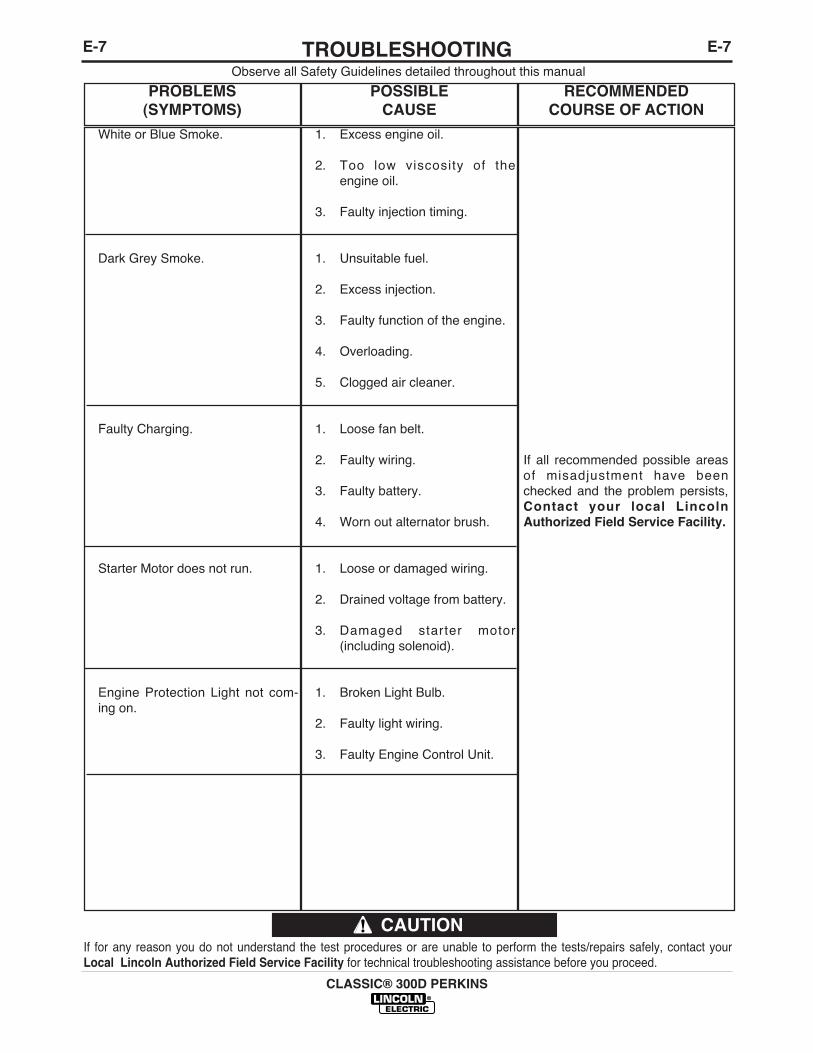
White or Blue Smoke.
Dark Grey Smoke.
Faulty Charging.
Starter Motor does not run.
Engine Protection Light not com-ing on.
1. Excess engine oil.
2. Too low viscosity of theengine oil.
3. Faulty injection timing.
1. Unsuitable fuel.
2. Excess injection.
3. Faulty function of the engine.
4. Overloading.
5. Clogged air cleaner.
1. Loose fan belt.
2. Faulty wiring.
3. Faulty battery.
4. Worn out alternator brush.
1. Loose or damaged wiring.
2. Drained voltage from battery.
3. Damaged starter motor(including solenoid).
1. Broken Light Bulb.
2. Faulty light wiring.
3. Faulty Engine Control Unit.
If all recommended possible areasof misadjustment have beenchecked and the problem persists,Contact your local LincolnAuthorized Field Service Facility.
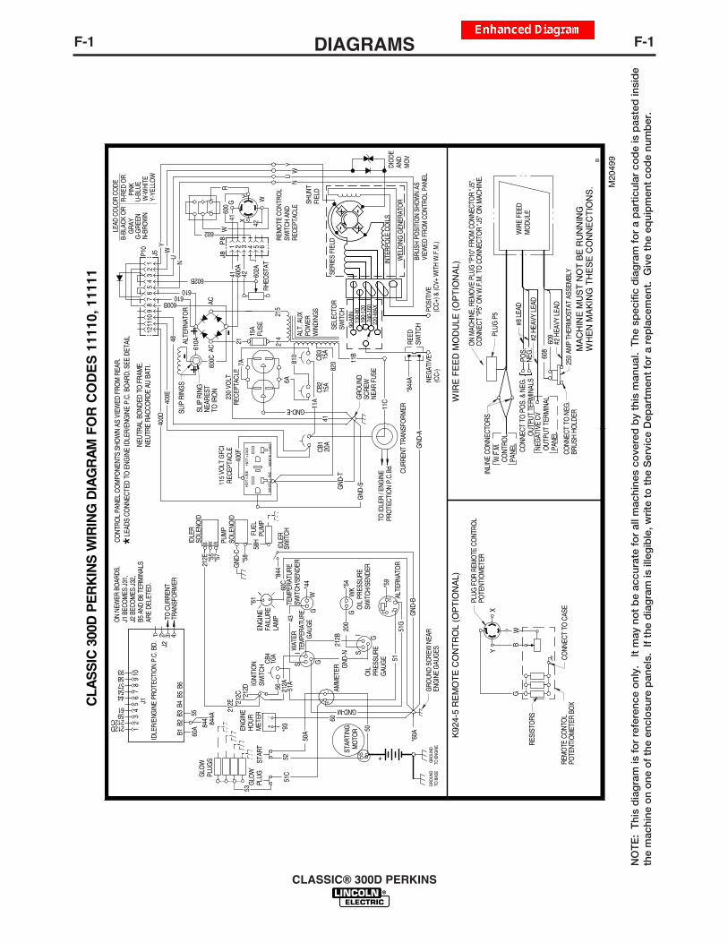
F-1DIAGRAMSF-1
CLASSIC® 300D PERKINS
WIR
E F
EE
D M
OD
ULE
(O
PT
ION
AL)
608
609
CLA
SS
IC 3
00D
PE
RK
INS
WIR
ING
DIA
GR
AM
FO
R C
OD
ES
111
10, 1
1111
B
M20
499
PLUG
P5
INLI
NE C
ONN
ECTO
RSW
.F.M
.CO
NTRO
LPA
NEL
CONN
ECT
TO P
OS.
& N
EG.
OUT
PUT
TERM
INAL
SPO
S.NE
G.
#8 L
EAD
#2 H
EAVY
LEA
D
#2 H
EAVY
LEA
D
NEG
ATIV
E CV
OUT
PUT
TERM
INAL
PANE
L
CONN
ECT
TO N
EG.
BRUS
H HO
LDER
250
AMP
THER
MO
STAT
ASS
EMBL
Y
MA
CH
INE
MU
ST
NO
T B
E R
UN
NIN
GW
HE
N M
AK
ING
TH
ES
E C
ON
NE
CT
ION
S.
WIR
E FE
EDM
ODU
LE
PLUG
FO
R RE
MO
TE C
ONT
ROL
POTE
NTIO
MET
ER
CONN
ECT
TO C
ASE
REM
OTE
CO
NTO
LPO
TENT
IOM
ETER
BO
X
RESI
STO
RS
K92
4-5
RE
MO
TE
CO
NT
RO
L (O
PT
ION
AL)
YX
BG
W
NEUT
RAL
BOND
ED T
O F
RAM
E.NE
UTRE
RAC
CORD
E AU
BAT
I.
CONT
ROL
PANE
L CO
MPO
NENT
S SH
OW
N AS
VIE
WED
FRO
M R
EAR.
ON
MAC
HINE
, REM
OVE
PLU
G "P
10" F
ROM
CO
NNEC
TOR
"J5"
.CO
NNEC
T "P
5" O
N W
.F.M
. TO
CO
NNEC
TOR
"J5"
ON
MAC
HINE
.
STAR
T+
52
+
AMM
ETER
IDLE
RSO
LENO
ID
-
-
51E
XC AL
TERN
ATO
R+
50
51C
53
S B +
60C
50A
51G
WK
G
S
S GW
GI
I
G
NEG
ATIV
E(C
C-)
POSI
TIVE
(CC+
) & (C
V+ W
ITH
W.F
.M.)
11B
41CB
215
A15
A
11A
CB3
810
115
VOLT
GFC
IRE
CEPT
ACLE
610610
600B
602B
NU
34
56
78
910
1112
48
400D
400E
21ALTE
RNAT
OR
600C
+-
SLIP
RIN
GS
SLIP
RIN
GNE
ARES
TTO
IRO
N
7A
6A
GND-E
230
VOLT
RECE
PTAC
LE
610A
+ -
215
ACAC
15A
FUSE
214 AL
T. A
UXPO
WER
WIN
DING
S
820
J5P10 Y
W
12
42 602A
4160
0
42
602
4160
0A
RHEO
STAT
654321P8
J8R
YX
WGW
NU
YW
--
++
INTE
RPO
LE C
OIL
S
SHUN
TFI
ELD
SERI
ES F
IELD
BRUS
H PO
SITI
ON
SHO
WN
ASVI
EWED
FRO
M C
ONT
ROL
PANE
L
SELE
CTO
RSW
ITCH
90-M
IN13
0-80
190-
120
240-
160
220-
MAX
WEL
DING
GEN
ERAT
OR
LEAD
CO
LOR
CODE
G-G
REEN
N-BR
OW
NU-
BLUE
W-W
HITE
Y-YE
LLO
W
B-BL
ACK
OR
G
RAY
R-RE
D O
R
PIN
K
GND
-S
REM
OTE
CO
NTRO
LSW
ITCH
AND
RECE
PTAC
LE
DIO
DEAN
DM
OV
CURR
ENT
TRAN
SFO
RMER
PUM
PSO
LENO
ID
TEM
PERA
TURE
SWIT
CH/S
ENDE
R
OIL
PRE
SSUR
ESW
ITCH
/SEN
DER
OIL
PRES
SURE
GAU
GE
WAT
ERTE
MPE
RATU
RE
G
AUG
E
GLO
WPL
UGS
GLO
WPL
UG
ENG
INE
HOUR
MET
ERIG
NITI
ON
SWIT
CH
GRO
UND
SCRE
W N
EAR
ENG
INE
GAU
GES
RWB
*57
*55
58H
*58
*93
60
51A
212A
212B
GND
-N20
0*5
4
*44
43
GND-M
*61
*212
C*2
12D
GND
-B
212E
*LEAD
S CO
NNEC
TED
TO E
NGIN
E ID
LER/
ENG
INE
P.C.
BO
ARD,
SEE
DET
AIL
*59*8
44
*844
AG
ND-A
*60A
CB1
20A
HO
T L
INE
HO
T L
OA
D
WH
ITE
LIN
EW
HIT
E L
OA
D
11C
400F
10A
CB4
56
GND
-C
GRO
UND
SCRE
WNE
AR F
USE
GRO
UND
TO B
ASE
GR
OUN
DTO
EN
GIN
E
GND
-TST
ARTI
NGM
OTO
R
FUEL
PUM
PEN
GIN
EFA
ILUR
ELA
MP
IDLE
RSW
ITCH
TO ID
LER
/ ENG
INE
PRO
TECT
ION
P.C.
Bd.
212E
TO C
URRE
NTTR
ANSF
ORM
ER
5560
A
9358575444
6159212C212D
B6B5
B4B3
B2B1
IDLE
R/EN
GIN
E PR
OTE
CTIO
N P.
C. B
D. J2
J110
98
76
54
32
1
4321
844 844A
REED
SWIT
CH
ON
NEW
ER B
OAR
DS,
J1 B
ECO
MES
J31
,J2
BEC
OM
ES J
32,
B5 A
ND B
6 TE
RMIN
ALS
ARE
DELE
TED.
NO
TE
: T
his
dia
gra
m is
fo
r re
fere
nce
onl
y.
It m
ay n
ot
be
accu
rate
fo
r al
l mac
hine
s co
vere
d b
y th
is m
anua
l. T
he s
pec
ific
dia
gra
m f
or
a p
artic
ular
co
de
is p
aste
d in
sid
eth
e m
achi
ne o
n o
ne o
f th
e en
clo
sure
pan
els.
If
the
dia
gra
m is
ille
gib
le, w
rite
to
the
Ser
vice
Dep
artm
ent
for
a re
pla
cem
ent.
Giv
e th
e eq
uip
men
t co
de
num
ber
.
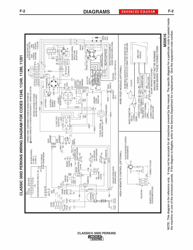
F-2DIAGRAMSF-2
CLASSIC® 300D PERKINS
NO
TE
: T
his
dia
gra
m is
fo
r re
fere
nce
onl
y.
It m
ay n
ot
be
accu
rate
fo
r al
l mac
hine
s co
vere
d b
y th
is m
anua
l. T
he s
pec
ific
dia
gra
m f
or
a p
artic
ular
co
de
is p
aste
d in
sid
eth
e m
achi
ne o
n o
ne o
f th
e en
clo
sure
pan
els.
If
the
dia
gra
m is
ille
gib
le, w
rite
to
the
Ser
vice
Dep
artm
ent
for
a re
pla
cem
ent.
Giv
e th
e eq
uip
men
t co
de
num
ber
.
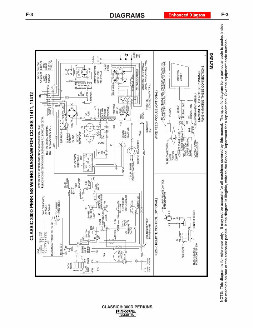
F-3DIAGRAMSF-3
CLASSIC® 300D PERKINS
NO
TE
: T
his
dia
gra
m is
fo
r re
fere
nce
onl
y.
It m
ay n
ot
be
accu
rate
fo
r al
l mac
hine
s co
vere
d b
y th
is m
anua
l. T
he s
pec
ific
dia
gra
m f
or
a p
artic
ular
co
de
is p
aste
d in
sid
eth
e m
achi
ne o
n o
ne o
f th
e en
clo
sure
pan
els.
If
the
dia
gra
m is
ille
gib
le, w
rite
to
the
Ser
vice
Dep
artm
ent
for
a re
pla
cem
ent.
Giv
e th
e eq
uip
men
t co
de
num
ber
.
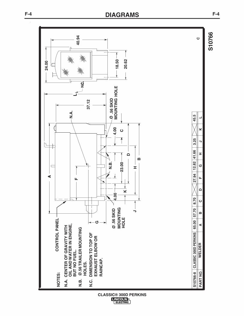
F-4DIAGRAMSF-4
CLASSIC® 300D PERKINS
.56
SK
IDO M
OU
NT
ING
HO
LE
O.5
6 S
KID
MO
UN
TIN
GH
OL
E
NO
TE
S:
OIL
AN
D W
AT
ER
IN E
NG
INE
,B
UT
NO
FU
EL
.
N.A
. C
EN
TE
R O
F G
RA
VIT
Y W
ITH
ON
.B.
.
56 T
RA
ILE
R M
OU
NT
ING
HO
LE
S.
S10
766
CP
AR
T N
O.
WE
LD
ER
AB
CD
FG
HJ
K
S10
766-
865
.00
57.7
08.
7027
.94
12.8
241
.66
3.25
CLA
SSIC
300
D P
ERK
INS
L
45.5
CO
NT
RO
L P
AN
EL
N.C
. D
IME
NS
ION
TO
TO
P O
FE
XH
AU
ST
EL
BO
W O
RR
AIN
CA
P.
18.5
0
20.6
2
40.9
4
24.0
0
37.1
2
F
G
BH
D
23.0
0C
4.00
4.00
N.A
.
N.B
.
J
K
A A
L
N.C
.C
.

NOTES
CLASSIC® 300D PERKINS
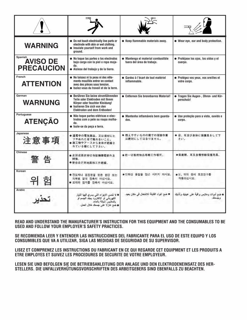
WARNING
AVISO DEPRECAUCION
ATTENTION
WARNUNG
ATENÇÃO
Spanish
French
German
Portuguese
Japanese
Chinese
Korean
Arabic
READ AND UNDERSTAND THE MANUFACTURER’S INSTRUCTION FOR THIS EQUIPMENT AND THE CONSUMABLES TO BEUSED AND FOLLOW YOUR EMPLOYER’S SAFETY PRACTICES.
SE RECOMIENDA LEER Y ENTENDER LAS INSTRUCCIONES DEL FABRICANTE PARA EL USO DE ESTE EQUIPO Y LOSCONSUMIBLES QUE VA A UTILIZAR, SIGA LAS MEDIDAS DE SEGURIDAD DE SU SUPERVISOR.
LISEZ ET COMPRENEZ LES INSTRUCTIONS DU FABRICANT EN CE QUI REGARDE CET EQUIPMENT ET LES PRODUITS AETRE EMPLOYES ET SUIVEZ LES PROCEDURES DE SECURITE DE VOTRE EMPLOYEUR.
LESEN SIE UND BEFOLGEN SIE DIE BETRIEBSANLEITUNG DER ANLAGE UND DEN ELEKTRODENEINSATZ DES HER-STELLERS. DIE UNFALLVERHÜTUNGSVORSCHRIFTEN DES ARBEITGEBERS SIND EBENFALLS ZU BEACHTEN.
● Do not touch electrically live parts orelectrode with skin or wet clothing.
● Insulate yourself from work andground.
● No toque las partes o los electrodosbajo carga con la piel o ropa moja-da.
● Aislese del trabajo y de la tierra.
● Ne laissez ni la peau ni des vête-ments mouillés entrer en contactavec des pièces sous tension.
● Isolez-vous du travail et de la terre.
● Berühren Sie keine stromführendenTeile oder Elektroden mit IhremKörper oder feuchter Kleidung!
● Isolieren Sie sich von denElektroden und dem Erdboden!
● Não toque partes elétricas e elec-trodos com a pele ou roupa molha-da.
● Isole-se da peça e terra.
● Keep flammable materials away.
● Mantenga el material combustiblefuera del área de trabajo.
● Gardez à l’écart de tout matérielinflammable.
● Entfernen Sie brennbarres Material!
● Mantenha inflamáveis bem guarda-dos.
● Wear eye, ear and body protection.
● Protéjase los ojos, los oídos y elcuerpo.
● Protégez vos yeux, vos oreilles etvotre corps.
● Tragen Sie Augen-, Ohren- und Kör-perschutz!
● Use proteção para a vista, ouvido ecorpo.

WARNING
AVISO DEPRECAUCION
ATTENTION
WARNUNG
ATENÇÃO
Spanish
French
German
Portuguese
Japanese
Chinese
Korean
Arabic
LEIA E COMPREENDA AS INSTRUÇÕES DO FABRICANTE PARA ESTE EQUIPAMENTO E AS PARTES DE USO, E SIGA ASPRÁTICAS DE SEGURANÇA DO EMPREGADOR.
● Keep your head out of fumes.● Use ventilation or exhaust to
remove fumes from breathing zone.
● Los humos fuera de la zona de res-piración.
● Mantenga la cabeza fuera de loshumos. Utilice ventilación oaspiración para gases.
● Gardez la tête à l’écart des fumées.● Utilisez un ventilateur ou un aspira-
teur pour ôter les fumées des zonesde travail.
● Vermeiden Sie das Einatmen vonSchweibrauch!
● Sorgen Sie für gute Be- undEntlüftung des Arbeitsplatzes!
● Mantenha seu rosto da fumaça.● Use ventilação e exhaustão para
remover fumo da zona respiratória.
● Turn power off before servicing.
● Desconectar el cable de ali-mentación de poder de la máquinaantes de iniciar cualquier servicio.
● Débranchez le courant avant l’entre-tien.
● Strom vor Wartungsarbeitenabschalten! (Netzstrom völlig öff-nen; Maschine anhalten!)
● Não opere com as tampas removidas.● Desligue a corrente antes de fazer
serviço.● Não toque as partes elétricas nuas.
● Do not operate with panel open orguards off.
● No operar con panel abierto oguardas quitadas.
● N’opérez pas avec les panneauxouverts ou avec les dispositifs deprotection enlevés.
● Anlage nie ohne Schutzgehäuseoder Innenschutzverkleidung inBetrieb setzen!
● Mantenha-se afastado das partesmoventes.
● Não opere com os paineis abertosou guardas removidas.

• Sales and Service through Subsidiaries and Distributors Worldwide •
Cleveland, Ohio 44117-1199 U.S.A. TEL: 216.481.8100 FAX: 216.486.1751 WEB SITE: www.lincolnelectric.com
• World's Leader in Welding and Cutting Products •