classic and r45 hub manual - chris king precision ... · classic and r45™ hub manual ... bearing...
TRANSCRIPT
Classic and R45™ Hub Manual
register onlinechrisking.com/warranty
year warranty5serial number
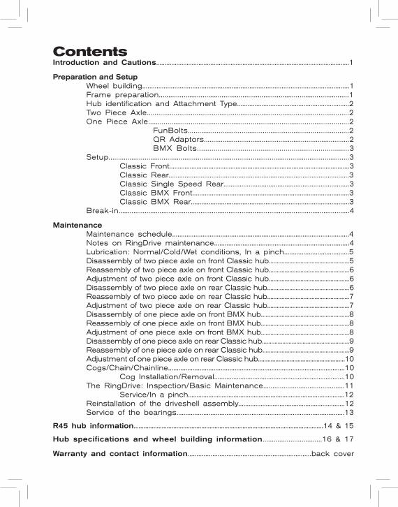
ContentsIntroduction and Cautions..................................................................................................................1
Preparation and Setup Wheel building....................................................................................................................1 Frame preparation....................................................................................................1 Hub identification and Attachment Type................................................................2 Two Piece Axle..........................................................................................................2 One Piece Axle........................................................................................................2 FunBolts....................................................................................2 QR Adaptors..............................................................................2 BMX Bolts...... . . . . . . . . . . . . . . . . . . . . . . . . . . . . . . . . . . . . . . . . . . . . . . . . . . . . . . . . . . . . . . . . . . . .3 Setup...............................................................................................................................3 Classic Front..........................................................................................................3 Classic Rear.....................................................................................................3 Classic Single Speed Rear......................................................................3 Classic BMX Front.........................................................................................3 Classic BMX Rear.........................................................................................3 Break-in............................................................................................................................4
Maintenance Maintenance schedule...................................................................................................4 Notes on RingDrive maintenance............................................................................4 Lubrication: Normal/Cold/Wet conditions, In a pinch.....................................5 Disassembly of two piece axle on front Classic hub...................................................5 Reassembly of two piece axle on front Classic hub...................................................6 Adjustment of two piece axle on front Classic hub...................................................6 Disassembly of two piece axle on rear Classic hub....................................................6 Reassembly of two piece axle on rear Classic hub....................................................7 Adjustment of two piece axle on rear Classic hub....................................................7 Disassembly of one piece axle on front BMX hub........................................................8 Reassembly of one piece axle on front BMX hub........................................................8 Adjustment of one piece axle on front BMX hub........................................................8 Disassembly of one piece axle on rear Classic hub........................................................9 Reassembly of one piece axle on rear Classic hub.......................................................9 Adjustment of one piece axle on rear Classic hub.......................................................10 Cogs/Chain/Chainline.....................................................................................................10 Cog Installation/Removal...........................................................................10 The RingDrive: Inspection/Basic Maintenance............................................11 Service/In a pinch.............................................................................................12 Reinstallation of the driveshell assembly..............................................................12 Service of the bearings..............................................................................................13
R45 hub information...................................................................................................................14 & 15
Hub specifications and wheel building information................................16 & 17
Warranty and contact information......................................................................back cover
See R45 Hub Information section on pages 14 and 15 for R45-specific information.
CongratulationsYou have just purchased the finest hubs available. With proper care and maintenance you will enjoy many years of the legendary performance you have come to expect from all Chris King Precision Components. This manual is designed to give you the information needed for the setup, use, and basic maintenance of your new hubs. As with all Chris King Precision Components, our hubs are superbly designed and manufactured, responsibly light, and meticulously finished. Our hubs feature our patented RingDrive engagement system spinning around an aluminum axle on four sets of ball and needle bearings. This combination, housed in an elegant aluminum shell, offers the solid and reliable performance demanded by serious cyclists. Like all of our components, our Classic hubs are user serviceable.
CautionsChris King hubs with two piece axles are designed to be used in conjunction with quick-release skewers. It is recommended that the skewer develop a minimum of 1100 lbs. of clamping force when set. For best performance, use skewers with steel shafts. Titanium shafted skewers are not recommended for use with front or rear suspension.Do not attempt to modify your two piece axles to accept any type of thru axle or one piece axle retention device. Do not use thread-locking compound on any part of your hub(s).The aluminum driveshells of the rear hubs are softer than the steel shells, and should only be used in conjunction with “spidered”-style cassettes. Avoid using individual cog-style cog sets with aluminum driveshells. We recommend using our aluminum or Ti cog lock rings when installing 9 and 10 speed drivetrains.Chris King hubs feature adjustable bearing preload. The bearings should be kept in proper adjustment for optimum product performance. Do not allow the adjustment to become loose, as this may cause a loss of performance and could lead to damage to the hubs.
Preparation and SetupWheel buildingHub dimensions for wheel building are available on pages 16 and 17.Chris King Classic Hubs are designed to work with 13, 14 and 15 gauge spokes. Radial lacing your Classic hubs is considered outside of the intended use and will void your warranty. We will not be responsible for damaged or destroyed hubs, any consequential damages, or any resulting labor costs due to radial lacing your Classic hub. Proper wheel building technique is essential in creating a strong wheel. Wheel building is a skill that requires proper training and specialized tools and should be done by a trained professional.The spoke tension on each side of the wheel should be as uniform as possible. Tension should not exceed 120kgf (1200N).See R45 Hub Information section on pages 14 and 15 for R45-specific information.
Frame PreparationCheck frame and fork dropouts to ensure that they are parallel to each other. Use an appropriate tool made by a reputable bicycle tool manufacturer. Unparallel dropouts may damage or compromise the performance of your new hub.
1
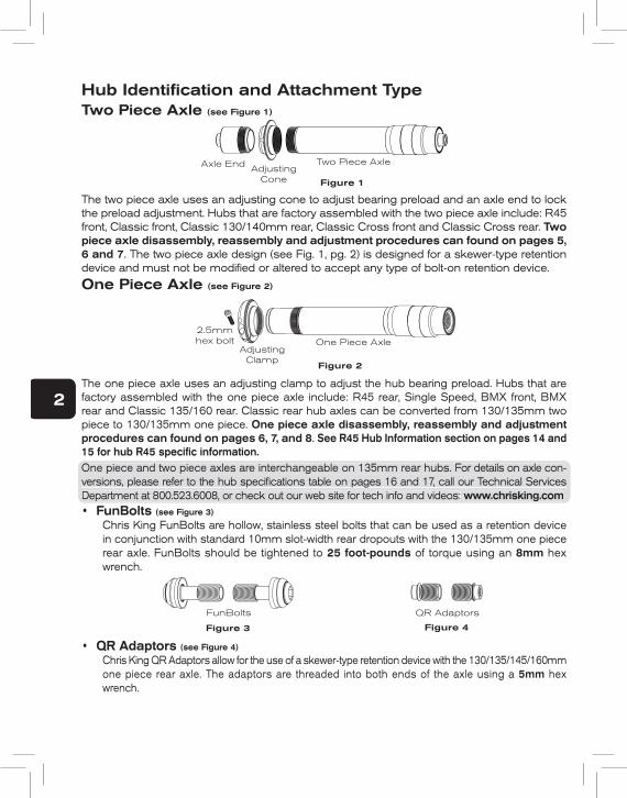
Hub Identifi cation and Attachment TypeTwo Piece Axle (see Figure 1)
Axle End AdjustingCone
Two Piece Axle
Figure 1
The two piece axle uses an adjusting cone to adjust bearing preload and an axle end to lock the preload adjustment. Hubs that are factory assembled with the two piece axle include: R45 front, Classic front, Classic 130/140mm rear, Classic Cross front and Classic Cross rear. Two piece axle disassembly, reassembly and adjustment procedures can found on pages 5, 6 and 7. The two piece axle design (see Fig. 1, pg. 2) is designed for a skewer-type retention device and must not be modifi ed or altered to accept any type of bolt-on retention device.
One Piece Axle (see Figure 2)
2.5mmhex bolt
AdjustingClamp
One Piece Axle
Figure 2
The one piece axle uses an adjusting clamp to adjust the hub bearing preload. Hubs that are factory assembled with the one piece axle include: R45 rear, Single Speed, BMX front, BMX rear and Classic 135/160 rear. Classic rear hub axles can be converted from 130/135mm two piece to 130/135mm one piece. One piece axle disassembly, reassembly and adjustment procedures can found on pages 6, 7, and 8. See R45 Hub Information section on pages 14 and 15 for hub R45 specifi c information.One piece and two piece axles are interchangeable on 135mm rear hubs. For details on axle con-versions, please refer to the hub specifi cations table on pages 16 and 17, call our Technical Services Department at 800.523.6008, or check out our web site for tech info and videos: www.chrisking.com• FunBolts (see Figure 3)
Chris King FunBolts are hollow, stainless steel bolts that can be used as a retention device in conjunction with standard 10mm slot-width rear dropouts with the 130/135mm one piece rear axle. FunBolts should be tightened to 25 foot-pounds of torque using an 8mm hex wrench.
FunBolts
Figure 3
QR Adaptors
Figure 4
• QR Adaptors (see Figure 4)
Chris King QR Adaptors allow for the use of a skewer-type retention device with the 130/135/145/160mm one piece rear axle. The adaptors are threaded into both ends of the axle using a 5mm hex wrench.
One piece and two piece axles are interchangeable on 135mm rear hubs. For details on axle con-versions, please refer to the hub specifi cations table on pages 16 and 17, call our Technical Services Department at 800.523.6008, or check out our web site for tech info and videos: www.chrisking.com
2
• BMX Axle BoltsChris King BMX hubs are supplied with 3/8”-16 x 1” socket cap axle bolts which should be tightened to 25 foot-pounds of torque using a 5/16” wrench. Replacements can be purchased at most high quality hardware stores. Use a bolt of grade 8 or equivalent. Under no circumstance should a quick release skewer be substituted for the axle bolts.
Setup• Classic Front
Chris King Classic front hubs are designed to work with 100mm fork drop out spacing. Do not attempt to use your hub with any other dropout spacing. The two piece axle design (see Fig. 1, pg. 2) is designed for a skewer-type retention device and must not be modified or altered to accept any type of bolt-on retention device.
• Classic RearChris King Classic rear hubs are designed to work with 130, 135. 140 and 145mm frame spacing. Do not attempt to use your hub with any other dropout spacing. The two piece axle (see Fig. 1, pg. 2) is designed for exclusive use with a skewer-type retention device and the hub can only be used with FunBolts by replacing the two piece axle with the one piece axle. The one piece axle design (see Fig. 2, pg. 2) can be used with Chris King FunBolts or with our QR adaptors, which allow for the use of a skewer-type retention device. Do not modify or alter either one piece or two piece axle systems to accept thru-bolt retention devices.
• Classic Single Speed RearChris King Single Speed rear hubs are compatible with 130 or 135mm frame spacing. Do not attempt to use your hub with any other dropout spacing. Our Single Speed rear hubs utilize our one piece axle design (see Fig. 2, pg. 2). The one piece axle can be used with Chris King FunBolts or with our QR adaptors, which allow for the use of a skewer-type retention device. Single Speed rear hub and cog set-up information can by found on pages 10 and 11.
• BMX FrontChris King BMX front hubs are designed to work with 100mm fork dropout spacing. Do not attempt to use your hub with dropout spacing different than for which it was intended. All BMX hubs utilize our one piece axle design and are attached to the frame with BMX Axle Bolts (see “BMX Axle Bolts”, pg. 3).
• BMX RearChris King BMX rear hubs are designed to work with 110mm frame dropout spacing. Do not attempt to use your hub with dropout spacing different than for which it was intended. BMX hubs utilize our one piece axle design and are attached to the frame with BMX Axle Bolts (see “BMX Axle Bolts”, pg. 3). Cog setup information can be found on pages 10 and 11.
The hub(s) come pre-adjusted from the factory. The adjustment has been made anticipating spoke tension and skewer compression. Because of variations in wheel-building practices, a minor adjustment should be performed upon completion of the wheel build. See the appropriate “Adjustment” pgs. 6 to 10, and check the hub before using.
3
The grease in your hub will provide optimum performance between 30°-110°F. The bearings and RingDrive engagement mechanism come lubricated with a specially formulated low shear grease. To maintain maximum performance in extreme temperatures see appropriate section under “Lubrication”, pg. 5.
Break-InOnce your new hub is placed in service, some settling may occur. Check adjustment by clamping wheel into frame with a quick-release skewer or with Chris King FunBolts. Ride for 5-10 minutes, check for play or binding, and readjust if necessary. Recheck after the first 1-5 hours of riding. Check cog lock ring on rear hubs after the first 20 hours of use, and tighten if necessary. Continue monitoring for the first 60 hours of use.During the first 60 hours of use, above average amounts of drag may be noticed. This is normal as the seals break in, and will soon diminish. If this causes chain sag in the rear while back-pedaling, increase the B-tension (cage tension) on the rear derailleur.The bearing grease is intentionally overpacked and excess grease may seep at the bearing seals during the break-in period.
MaintenanceSee R45 Hub Information section on pages 14 and 15 for R45-specific information.
Maintenance scheduleChris King Classic Hubs are designed to provide long life and high performance. Beyond an occasional adjustment, the only maintenance necessary is cleaning, lubricating the RingDrive (see “The RingDrive”, pg. 11), and re-lubricating the bearings (see “Service of the bearings”, pg. 11). Riding conditions will determine how often to maintain your hubs. As a beginning guideline, your hubs should be maintained every 6-12 months in normal and dry conditions and every 3 months in wet or muddy conditions. The bearings in your new Chris King hubs are of the highest quality. However, all bearings will settle and eventually wear with use. Since looseness or “play” in the bearing assembly can develop as a result of wear, Chris King hubs have been designed with an adjustable bearing preload mechanism and any normal play can be eliminated (see the appropriate “Adjustment” section, pgs. 6 to 10).
Notes on RingDrive™ maintenanceNormal preventative maintenance of the RingDrive is simple and can be performed using basic tools (see “The RingDrive”, pg. 9). In many cases, a minor cleaning and reapplication of lubricant is all that may be necessary. Judging when to perform this basic maintenance is determined by riding style and conditions. As a beginning guideline, your hubs should be maintained every 6-12 months in normal and dry conditions and every 3 months in wet or muddy conditions.If foreign debris is detectable in the grease and/or the grease looks hard or dry, a complete servicing (removal and cleaning) of the RingDrive should be performed. Complete service includes the removal of the RingDrive engagement mechanism and requires the use of our Hub Service Tool. See any authorized Chris King dealer for complete service or you may purchase a Hub Service Tool Kit from your dealer or directly from Chris King Precision Components. Chris King Precision Components provides overhaul services at reason-able rates. Contact the Customer Service hotline at 800-523-6008 for details.
LubricationSee R45 Hub Information section on pages 14 and 15 for R45-specific information.
Normal conditionsIn normal riding conditions (30°-110°F), our RingDrive grease is recommended for the bearings and the RingDrive. Do not substitute other brands of grease, as they may cause premature wear and/or be too sticky for the helix of the RingDrive inhibiting proper engagement.
Cold conditionsTo ensure proper engagement in sub-freezing conditions, first be sure that there is no water or moisture inside the hubshell. The hub may require an overhaul to ensure that the hub interior is completely water-free. A quality 10w synthetic oil (such as Mobil 1® 10w-30 or equivalent) works well over a wide range of temperatures, even in subzero conditions. Mix the RingDrive Lube in the RingDrive area, especially on the helical splines of the driveshell, with 5-10 drops of Tri-flow™ or a quality 10w synthetic oil. Do not over fill.
Wet conditionsRiding in wet conditions necessitates more frequent service. Often this is as simple as removing the axle and driveshell from the hub, removing any moisture from inside the hub shell, and applying more grease to the needle bearing. This should not replace periodic complete disassembly and maintenance, especially in extreme or prolonged wet conditions. Since it is nearly impossible to seal a hub from water and still have it spin freely, we have designed our hubs to be able to operate normally with some water intrusion. Although the bearings are stainless steel and will resist water induced corrosion, the lubricant will eventu-ally deteriorate, leading to premature bearing wear and possible failure. High-pressure spray washing, transporting or riding the bicycle in the rain, or submersion in water while riding can all lead to lubricant contamination by water. Be aware of these situations and service more frequently when they occur.
In a pinch...If Chris King RingDrive lube in not available, a quality 10w synthetic oil may be substituted. Do not substitute other brands of grease, as they may be too sticky for the helix of the RingDrive. Running the hub on oil will cause the RingDrive to be more audible, yet functionally no different.If you have any additional questions, please call our Technical Services Department at 800.523.6008, or check out our web site for tech info and videos: www.chrisking.com
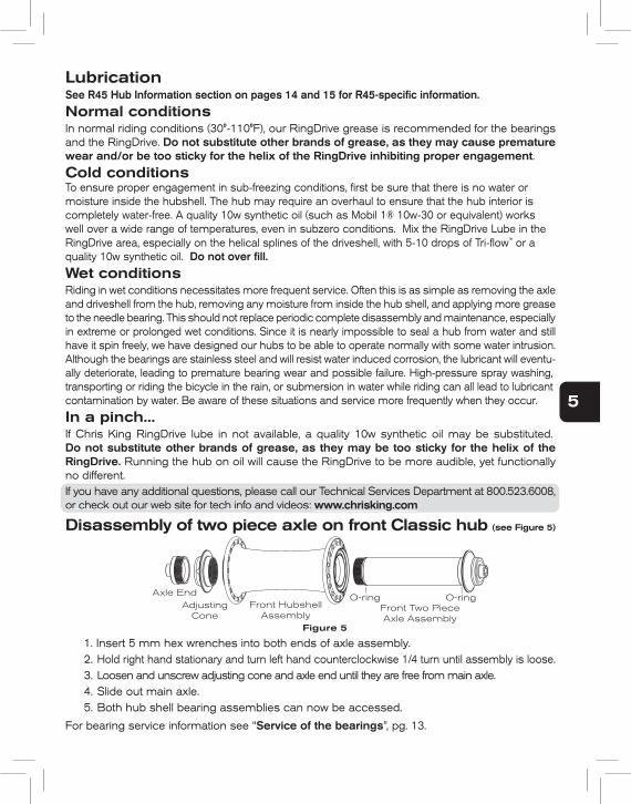
Disassembly of two piece axle on front Classic hub (see Figure 5)
Axle EndAdjusting
ConeFront Hubshell
AssemblyFront Two PieceAxle Assembly
Figure 5
O-ring O-ring
1. Insert 5 mm hex wrenches into both ends of axle assembly.2. Hold right hand stationary and turn left hand counterclockwise 1/4 turn until assembly is loose.3. Loosen and unscrew adjusting cone and axle end until they are free from main axle.4. Slide out main axle.5. Both hub shell bearing assemblies can now be accessed.
For bearing service information see “Service of the bearings”, pg. 13.
4
LubricationSee R45 Hub Information section on pages 14 and 15 for R45-specifi c information.
Normal conditionsIn normal riding conditions (30°-110°F), our RingDrive grease is recommended for the bearings and the RingDrive. Do not substitute other brands of grease, as they may cause premature wear and/or be too sticky for the helix of the RingDrive inhibiting proper engagement.
Cold conditionsTo ensure proper engagement in sub-freezing conditions, fi rst be sure that there is no water or moisture inside the hubshell. The hub may require an overhaul to ensure that the hub interior is completely water-free. A quality 10w synthetic oil (such as Mobil 1® 10w-30 or equivalent) works well over a wide range of temperatures, even in subzero conditions. Mix the RingDrive Lube in the RingDrive area, especially on the helical splines of the driveshell, with 5-10 drops of Tri-fl ow™ or a quality 10w synthetic oil. Do not over fi ll.
Wet conditionsRiding in wet conditions necessitates more frequent service. Often this is as simple as removing the axle and driveshell from the hub, removing any moisture from inside the hub shell, and applying more grease to the needle bearing. This should not replace periodic complete disassembly and maintenance, especially in extreme or prolonged wet conditions. Since it is nearly impossible to seal a hub from water and still have it spin freely, we have designed our hubs to be able to operate normally with some water intrusion. Although the bearings are stainless steel and will resist water induced corrosion, the lubricant will eventu-ally deteriorate, leading to premature bearing wear and possible failure. High-pressure spray washing, transporting or riding the bicycle in the rain, or submersion in water while riding can all lead to lubricant contamination by water. Be aware of these situations and service more frequently when they occur.
In a pinch...If Chris King RingDrive lube in not available, a quality 10w synthetic oil may be substituted. Do not substitute other brands of grease, as they may be too sticky for the helix of the RingDrive. Running the hub on oil will cause the RingDrive to be more audible, yet functionally no different.If you have any additional questions, please call our Technical Services Department at 800.523.6008, or check out our web site for tech info and videos: www.chrisking.com
Disassembly of two piece axle on front Classic hub (see Figure 5)
Axle EndAdjusting
ConeFront Hubshell
AssemblyFront Two PieceAxle Assembly
Figure 5
O-ring O-ring
1. Insert 5 mm hex wrenches into both ends of axle assembly.2. Hold right hand stationary and turn left hand counterclockwise 1/4 turn until assembly is loose.3. Loosen and unscrew adjusting cone and axle end until they are free from main axle.4. Slide out main axle.5. Both hub shell bearing assemblies can now be accessed.
For bearing service information see “Service of the bearings”, pg. 13.
If you have any additional questions, please call our Technical Services Department at 800.523.6008, or check out our web site for tech info and videos: www.chrisking.com
5
Reassembly of two piece axle on front Classic hub (see
Figure 5)
1. Lightly grease threads on axle, adjusting cone and axle end. Apply two drops of Tri-flow™ or a quality 10w synthetic oil to axle O-ring.
2. Insert main axle into hub shell.3. If axle end and adjusting cone are assembled as one unit, disassemble by threading
axle end out of adjusting cone.4. Thread adjusting cone onto the protruding threads of main axle.5. Lightly snug adjusting cone up to bearing.6. Thread axle end into adjusting cone until it stops.7. Proceed to “Adjustment of two piece axle on front Classic hub”, below.
Adjustment of two piece axle on front Classic hub (see
Figure 5)
1. Insert 5 mm hex wrenches into both ends of axle assembly.2. Hold right hand stationary and turn left hand counterclockwise 1/4 turn until assembly is
loose.3. Hold hex wrenches stationary and adjust bearing preload with adjusting cone.4. Advance adjusting cone until it just contacts bearing, then back off approximately 1/16
turn (this allows for axle compression while under skewer clamp pressure).5. Once preload is set, tighten axle assembly to 110 inch-pounds.6. Double check adjustment by clamping wheel into fork with quick-release. Check for
play or binding, and readjust if needed.
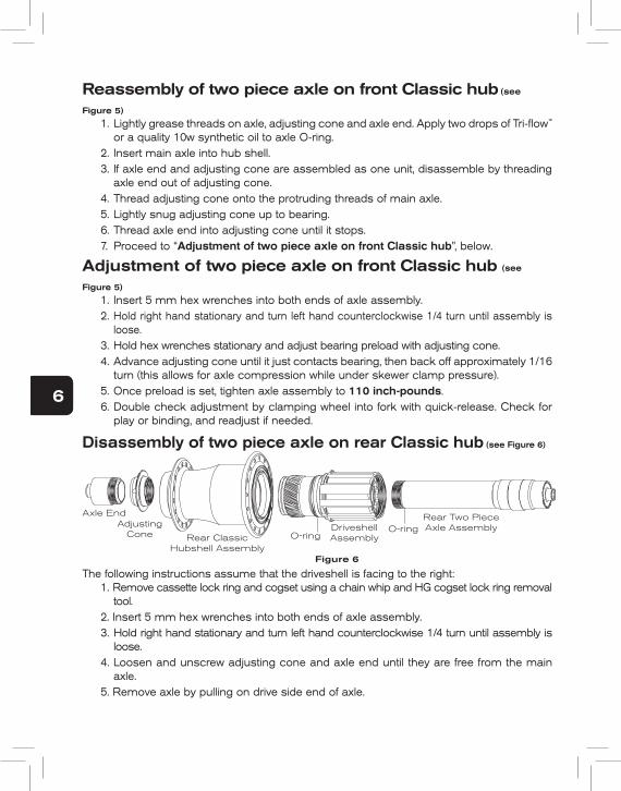
Disassembly of two piece axle on rear Classic hub (see Figure 6)
Rear ClassicHubshell Assembly
DriveshellAssembly
Rear Two Piece Axle Assembly
Figure 6
Axle EndAdjusting
ConeO-ring
O-ring
The following instructions assume that the driveshell is facing to the right:1. Remove cassette lock ring and cogset using a chain whip and HG cogset lock ring removal
tool.2. Insert 5 mm hex wrenches into both ends of axle assembly.3. Hold right hand stationary and turn left hand counterclockwise 1/4 turn until assembly is
loose.4. Loosen and unscrew adjusting cone and axle end until they are free from the main
axle.5. Remove axle by pulling on drive side end of axle.
6. Hold hub or wheel in one hand and pull driveshell out with the other. 7. Hub shell bearings, RingDrive engagement and driveshell bearing assemblies can now be
accessed.
For RingDrive inspection and maintenance information, see “The RingDrive”, pg. 11. For bearing service information see “Service of the bearings”, pg. 13.Further disassembly requires specialized tools. These come individually or in the Chris King Hub Service Tool Kit, which is available at any authorized Chris King dealer, or directly from Chris King Precision Components.
Reassembly of two piece axle on rear Classic hub (see Figure 6)
The following instructions assume that the driveshell is facing to the right:1. Lightly grease threads on axle, adjusting cone and axle end. Apply two drops of Tri-flow™
or a quality 10w synthetic oil to O-ring on axle and driveshell.2. Insert driveshell into the hub shell; turn in a clockwise motion while letting it pull itself
in. A distinctive click sound will indicate that the driveshell is firmly seated.3. Insert main axle through driveshell. The axle is properly seated when the threaded end
appears through the bearing and the end is flush with the end of the hub shell.4. If axle end and adjusting cone are assembled as one unit, disassemble by threading
axle end out of adjusting cone.5. Thread adjusting cone onto the protruding threads of main axle.6. Thread axle end into adjusting cone until it stops.7. Proceed to “Adjustment of two piece axle on rear Classic hub”, below.
Note: To improve performance, the axles have been precisely matched with the needle bearings in the driveshell. Be sure to combine only like numbered parts, (e.g., #3 axle with #3 needle bearing race).
Adjustment of two piece axle on rear Classic hub (see Figure 6)
The following instructions assume that the driveshell is facing to the right:1. Insert 5 mm hex wrenches into both ends of the axle assembly.2. Hold right hand stationary and turn left hand counterclockwise 1/4 turn until the assembly is
loose.3. Hold hex wrenches stationary and adjust bearing preload with the adjusting cone. You
may use the hub cone adjusting tool if necessary.4. Advance adjusting cone until it contacts bearing. The rear hub takes a slightly higher
amount of preload than “no play”, since some settling may occur while riding.5. Once preload is set, tighten axle end to 110 inch-pounds. 6. Check adjustment by clamping wheel into frame with quick-release. Ride for 5-10
minutes, check for play or binding, and readjust as necessary. Double check adjustment after the first 5-10 miles of riding.
Note: Correct adjustment of the rear hub is necessary for proper engagement of the RingDrive.
If the hub is run loose, the RingDrive may not engage properly and could lead to permanent damage of the internal parts.
6
6. Hold hub or wheel in one hand and pull driveshell out with the other. 7. Hub shell bearings, RingDrive engagement and driveshell bearing assemblies can now be
accessed.
For RingDrive inspection and maintenance information, see “The RingDrive”, pg. 11. For bearing service information see “Service of the bearings”, pg. 13.Further disassembly requires specialized tools. These come individually or in the Chris King Hub Service Tool Kit, which is available at any authorized Chris King dealer, or directly from Chris King Precision Components.
Reassembly of two piece axle on rear Classic hub (see Figure 6)
The following instructions assume that the driveshell is facing to the right:1. Lightly grease threads on axle, adjusting cone and axle end. Apply two drops of Tri-fl ow™
or a quality 10w synthetic oil to O-ring on axle and driveshell.2. Insert driveshell into the hub shell; turn in a clockwise motion while letting it pull itself
in. A distinctive click sound will indicate that the driveshell is fi rmly seated.3. Insert main axle through driveshell. The axle is properly seated when the threaded end
appears through the bearing and the end is fl ush with the end of the hub shell.4. If axle end and adjusting cone are assembled as one unit, disassemble by threading
axle end out of adjusting cone.5. Thread adjusting cone onto the protruding threads of main axle.6. Thread axle end into adjusting cone until it stops.7. Proceed to “Adjustment of two piece axle on rear Classic hub”, below.
Note: To improve performance, the axles have been precisely matched with the needle bearings in the driveshell. Be sure to combine only like numbered parts, (e.g., #3 axle with #3 needle bearing race).
Adjustment of two piece axle on rear Classic hub (see Figure 6)
The following instructions assume that the driveshell is facing to the right:1. Insert 5 mm hex wrenches into both ends of the axle assembly.2. Hold right hand stationary and turn left hand counterclockwise 1/4 turn until the assembly is
loose.3. Hold hex wrenches stationary and adjust bearing preload with the adjusting cone. You
may use the hub cone adjusting tool if necessary.4. Advance adjusting cone until it contacts bearing. The rear hub takes a slightly higher
amount of preload than “no play”, since some settling may occur while riding.5. Once preload is set, tighten axle end to 110 inch-pounds. 6. Check adjustment by clamping wheel into frame with quick-release. Ride for 5-10
minutes, check for play or binding, and readjust as necessary. Double check adjustment after the fi rst 5-10 miles of riding.
Note: Correct adjustment of the rear hub is necessary for proper engagement of the RingDrive.
If the hub is run loose, the RingDrive may not engage properly and could lead to permanent damage of the internal parts.
Further disassembly requires specialized tools. These come individually or in the Chris King Hub Service Tool Kit, which is available at any authorized Chris King dealer, or directly from Chris King Precision Components.
Note: To improve performance, the axles have been precisely matched with the needle bearings in the driveshell. Be sure to combine only like numbered parts, (e.g., #3 axle with #3 needle bearing race).
Note: Correct adjustment of the rear hub is necessary for proper engagement of the RingDrive.If the hub is run loose, the RingDrive may not engage properly and could lead to permanent damage of the internal parts.
7
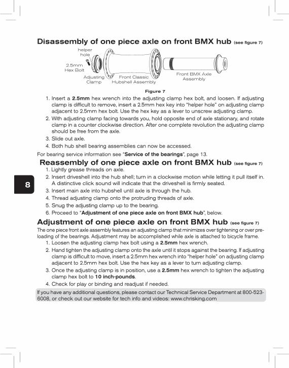
Disassembly of one piece axle on front BMX hub (see fi gure 7)
2.5mm Hex Bolt
AdjustingClamp
Front ClassicHubshell Assembly
Front BMX AxleAssembly
Figure 7
helper hole
1. Insert a 2.5mm hex wrench into the adjusting clamp hex bolt, and loosen. If adjusting clamp is diffi cult to remove, insert a 2.5mm hex key into “helper hole” on adjusting clamp adjacent to 2.5mm hex bolt. Use the hex key as a lever to unscrew adjusting clamp.
2. With adjusting clamp facing towards you, hold opposite end of axle stationary, and rotate clamp in a counter clockwise direction. After one complete revolution the adjusting clamp should be free from the axle.
3. Slide out axle.4. Both hub shell bearing assemblies can now be accessed.
For bearing service information see “Service of the bearings”, page 13.
Reassembly of one piece axle on front BMX hub (see fi gure 7)
1. Lightly grease threads on axle. 2. Insert driveshell into the hub shell; turn in a clockwise motion while letting it pull itself in.
A distinctive click sound will indicate that the driveshell is fi rmly seated.3. Insert main axle into hubshell until axle is through the hub.4. Thread adjusting clamp onto the protruding threads of axle.5. Snug the adjusting clamp up to the bearing.6. Proceed to “Adjustment of one piece axle on front BMX hub”, below.
Adjustment of one piece axle on front BMX hub (see fi gure 7)
The one piece front axle assembly features an adjusting clamp that minimizes over tightening or over pre-loading of the bearings. Adjustment may be accomplished while axle is attached to bicycle frame.
1. Loosen the adjusting clamp hex bolt using a 2.5mm hex wrench.2. Hand tighten the adjusting clamp onto the axle until it stops against the bearing. If adjusting
clamp is diffi cult to move, insert a 2.5mm hex wrench into “helper hole” on adjusting clamp adjacent to 2.5mm hex bolt. Use the hex key as a lever to turn adjusting clamp.
3. Once the adjusting clamp is in position, use a 2.5mm hex wrench to tighten the adjusting clamp hex bolt to 10 inch-pounds.
4. Check for play or binding and readjust if needed.
If you have any additional questions, please contact our Technical Service Department at 800-523-6008, or check out our website for tech info and videos: www.chrisking.comIf you have any additional questions, please contact our Technical Service Department at 800-523-6008, or check out our website for tech info and videos: www.chrisking.com
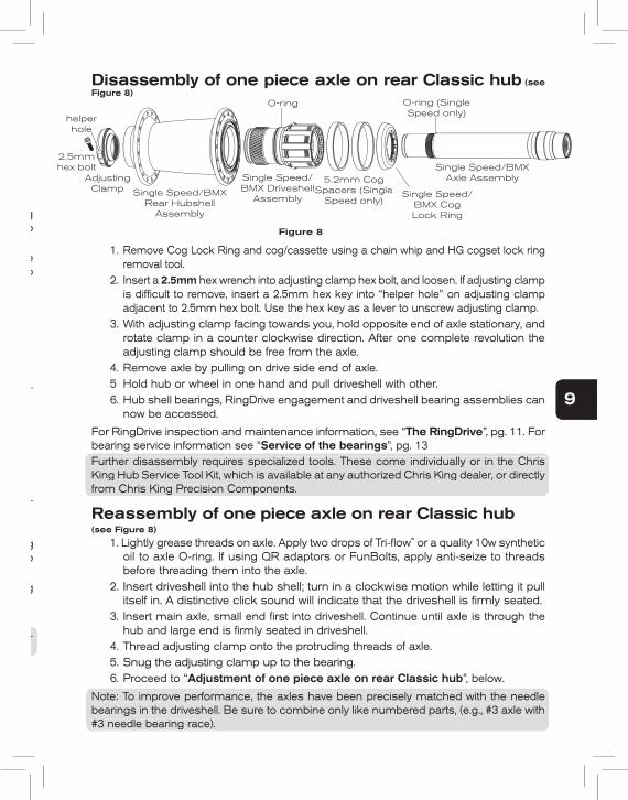
Disassembly of one piece axle on rear Classic hub (see Figure 8)
1. Remove Cog Lock Ring and cog/cassette using a chain whip and HG cogset lock ring removal tool.
2. Insert a 2.5mm hex wrench into adjusting clamp hex bolt, and loosen. If adjusting clamp is diffi cult to remove, insert a 2.5mm hex key into “helper hole” on adjusting clamp adjacent to 2.5mm hex bolt. Use the hex key as a lever to unscrew adjusting clamp.
3. With adjusting clamp facing towards you, hold opposite end of axle stationary, and rotate clamp in a counter clockwise direction. After one complete revolution the adjusting clamp should be free from the axle.
4. Remove axle by pulling on drive side end of axle.5 Hold hub or wheel in one hand and pull driveshell with other. 6. Hub shell bearings, RingDrive engagement and driveshell bearing assemblies can
now be accessed.
For RingDrive inspection and maintenance information, see “The RingDrive”, pg. 11. For bearing service information see “Service of the bearings”, pg. 13Further disassembly requires specialized tools. These come individually or in the Chris King Hub Service Tool Kit, which is available at any authorized Chris King dealer, or directly from Chris King Precision Components.
Reassembly of one piece axle on rear Classic hub (see Figure 8)
1. Lightly grease threads on axle. Apply two drops of Tri-fl ow™ or a quality 10w synthetic oil to axle O-ring. If using QR adaptors or FunBolts, apply anti-seize to threads before threading them into the axle.
2. Insert driveshell into the hub shell; turn in a clockwise motion while letting it pull itself in. A distinctive click sound will indicate that the driveshell is fi rmly seated.
3. Insert main axle, small end fi rst into driveshell. Continue until axle is through the hub and large end is fi rmly seated in driveshell.
4. Thread adjusting clamp onto the protruding threads of axle.5. Snug the adjusting clamp up to the bearing.6. Proceed to “Adjustment of one piece axle on rear Classic hub”, below.
Note: To improve performance, the axles have been precisely matched with the needle bearings in the driveshell. Be sure to combine only like numbered parts, (e.g., #3 axle with #3 needle bearing race).
5.2mm Cog Spacers (Single
Speed only)Single Speed/
BMX Cog Lock Ring
Single Speed/BMXAxle AssemblySingle Speed/
BMX Driveshell Assembly
Single Speed/BMXRear Hubshell
Assembly
AdjustingClamp
Figure 8
2.5mmhex bolt
O-ring O-ring (Single Speed only)
8
Disassembly of one piece axle on front BMX hub (see fi gure 7)
2.5mm Hex Bolt
AdjustingClamp
Front ClassicHubshell Assembly
Front BMX AxleAssembly
Figure 7
helper hole
1. Insert a 2.5mm hex wrench into the adjusting clamp hex bolt, and loosen. If adjusting clamp is diffi cult to remove, insert a 2.5mm hex key into “helper hole” on adjusting clamp adjacent to 2.5mm hex bolt. Use the hex key as a lever to unscrew adjusting clamp.
2. With adjusting clamp facing towards you, hold opposite end of axle stationary, and rotate clamp in a counter clockwise direction. After one complete revolution the adjusting clamp should be free from the axle.
3. Slide out axle.4. Both hub shell bearing assemblies can now be accessed.
For bearing service information see “Service of the bearings”, page 13.
Reassembly of one piece axle on front BMX hub (see fi gure 7)
1. Lightly grease threads on axle. 2. Insert driveshell into the hub shell; turn in a clockwise motion while letting it pull itself in.
A distinctive click sound will indicate that the driveshell is fi rmly seated.3. Insert main axle into hubshell until axle is through the hub.4. Thread adjusting clamp onto the protruding threads of axle.5. Snug the adjusting clamp up to the bearing.6. Proceed to “Adjustment of one piece axle on front BMX hub”, below.
Adjustment of one piece axle on front BMX hub (see fi gure 7)
The one piece front axle assembly features an adjusting clamp that minimizes over tightening or over pre-loading of the bearings. Adjustment may be accomplished while axle is attached to bicycle frame.
1. Loosen the adjusting clamp hex bolt using a 2.5mm hex wrench.2. Hand tighten the adjusting clamp onto the axle until it stops against the bearing. If adjusting
clamp is diffi cult to move, insert a 2.5mm hex wrench into “helper hole” on adjusting clamp adjacent to 2.5mm hex bolt. Use the hex key as a lever to turn adjusting clamp.
3. Once the adjusting clamp is in position, use a 2.5mm hex wrench to tighten the adjusting clamp hex bolt to 10 inch-pounds.
4. Check for play or binding and readjust if needed.
If you have any additional questions, please contact our Technical Service Department at 800-523-6008, or check out our website for tech info and videos: www.chrisking.comIf you have any additional questions, please contact our Technical Service Department at 800-523-
Disassembly of one piece axle on rear Classic hub (see Figure 8)
1. Remove Cog Lock Ring and cog/cassette using a chain whip and HG cogset lock ring removal tool.
2. Insert a 2.5mm hex wrench into adjusting clamp hex bolt, and loosen. If adjusting clamp is diffi cult to remove, insert a 2.5mm hex key into “helper hole” on adjusting clamp adjacent to 2.5mm hex bolt. Use the hex key as a lever to unscrew adjusting clamp.
3. With adjusting clamp facing towards you, hold opposite end of axle stationary, and rotate clamp in a counter clockwise direction. After one complete revolution the adjusting clamp should be free from the axle.
4. Remove axle by pulling on drive side end of axle.5 Hold hub or wheel in one hand and pull driveshell with other. 6. Hub shell bearings, RingDrive engagement and driveshell bearing assemblies can
now be accessed.
For RingDrive inspection and maintenance information, see “The RingDrive”, pg. 11. For bearing service information see “Service of the bearings”, pg. 13Further disassembly requires specialized tools. These come individually or in the Chris King Hub Service Tool Kit, which is available at any authorized Chris King dealer, or directly from Chris King Precision Components.
Reassembly of one piece axle on rear Classic hub (see Figure 8)
1. Lightly grease threads on axle. Apply two drops of Tri-fl ow™ or a quality 10w synthetic oil to axle O-ring. If using QR adaptors or FunBolts, apply anti-seize to threads before threading them into the axle.
2. Insert driveshell into the hub shell; turn in a clockwise motion while letting it pull itself in. A distinctive click sound will indicate that the driveshell is fi rmly seated.
3. Insert main axle, small end fi rst into driveshell. Continue until axle is through the hub and large end is fi rmly seated in driveshell.
4. Thread adjusting clamp onto the protruding threads of axle.5. Snug the adjusting clamp up to the bearing.6. Proceed to “Adjustment of one piece axle on rear Classic hub”, below.
Note: To improve performance, the axles have been precisely matched with the needle bearings in the driveshell. Be sure to combine only like numbered parts, (e.g., #3 axle with #3 needle bearing race).
5.2mm Cog Spacers (Single
Speed only)Single Speed/
BMX Cog Lock Ring
Single Speed/BMXAxle AssemblySingle Speed/
BMX Driveshell Assembly
Single Speed/BMXRear Hubshell
Assembly
AdjustingClamp
Figure 8
2.5mmhex bolt
O-ring O-ring (Single Speed only)
Further disassembly requires specialized tools. These come individually or in the Chris King Hub Service Tool Kit, which is available at any authorized Chris King dealer, or directly from Chris King Precision Components.
Note: To improve performance, the axles have been precisely matched with the needle bearings in the driveshell. Be sure to combine only like numbered parts, (e.g., #3 axle with #3 needle bearing race).
9
helper hole
Adjustment of one piece axle on rear Classic hub (see Figure 8)
The one piece rear axle assembly features an adjusting clamp that minimizes over tightening or over preloading of the bearings. Adjustment may be accomplished while axle is attached to bicycle frame.
1. Loosen the adjusting clamp hex bolt using a 2.5mm hex wrench.2. Hand tighten the adjusting clamp onto the axle until it stops against the bearing. If
adjusting clamp is diffi cult to move, insert a 2.5mm hex wrench into “helper hole” on adjusting clamp adjacent to 2.5mm hex bolt. Use the hex key as a lever to turn adjusting clamp.
3. Once the adjusting clamp is in position, use a 2.5mm hex wrench to tighten the adjusting clamp hex bolt to 10 inch-pounds.
4. Check for play or binding and readjust if needed.
Note: Correct adjustment of the rear hub is necessary for proper engagement of the RingDrive. If the hub is run loose, the RingDrive may not engage properly and could lead to permanent damage of the internal parts.
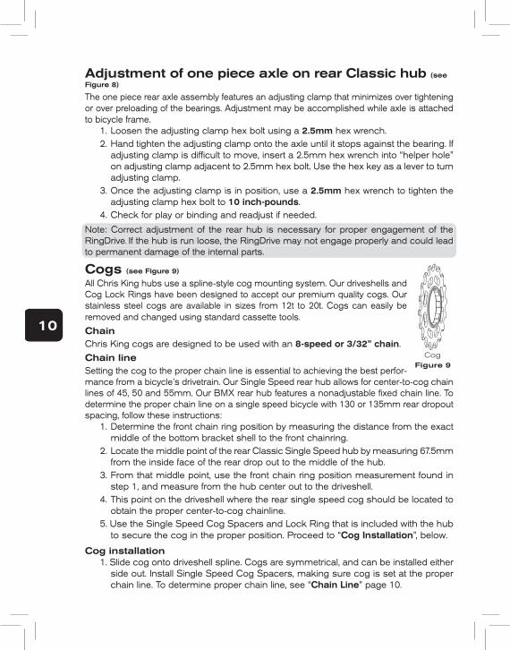
Cogs (see Figure 9)
All Chris King hubs use a spline-style cog mounting system. Our driveshells and Cog Lock Rings have been designed to accept our premium quality cogs. Our stainless steel cogs are available in sizes from 12t to 20t. Cogs can easily be removed and changed using standard cassette tools.
ChainChris King cogs are designed to be used with an 8-speed or 3/32” chain.
Chain lineSetting the cog to the proper chain line is essential to achieving the best perfor-mance from a bicycle’s drivetrain. Our Single Speed rear hub allows for center-to-cog chain lines of 45, 50 and 55mm. Our BMX rear hub features a nonadjustable fi xed chain line. To determine the proper chain line on a single speed bicycle with 130 or 135mm rear dropout spacing, follow these instructions:
1. Determine the front chain ring position by measuring the distance from the exact middle of the bottom bracket shell to the front chainring.
2. Locate the middle point of the rear Classic Single Speed hub by measuring 67.5mm from the inside face of the rear drop out to the middle of the hub.
3. From that middle point, use the front chain ring position measurement found in step 1, and measure from the hub center out to the driveshell.
4. This point on the driveshell where the rear single speed cog should be located to obtain the proper center-to-cog chainline.
5. Use the Single Speed Cog Spacers and Lock Ring that is included with the hub to secure the cog in the proper position. Proceed to “Cog Installation”, below.
Cog installation1. Slide cog onto driveshell spline. Cogs are symmetrical, and can be installed either
side out. Install Single Speed Cog Spacers, making sure cog is set at the proper chain line. To determine proper chain line, see “Chain Line” page 10.
Note: Correct adjustment of the rear hub is necessary for proper engagement of the RingDrive. If the hub is run loose, the RingDrive may not engage properly and could lead to permanent damage of the internal parts.
10
Figure 9Cog
2. Thread Single Speed Cog Lock Ring onto driveshell.3. Insert HG cassette lock ring tool into Cog Lock Ring, and tighten to 20 foot-
pounds.
Cog removal1. Using a chainwhip, hold cog stationary from counterclockwise rotation.2. Insert HG cassette lock ring tool into Cog Lock Ring.3. Loosen Cog Lock Ring by rotating it until it is free from driveshell.4. Slide cog from driveshell spline.
Additional SupportDigital movies are available on our web site to better help you keep your hubs and headsets performing at their best. Some are narrated by Chris King as he demonstrates proper headset and hub maintenance and overhaul procedures. Check our web site often for updated movies and technical information produced in an effort to help you, our custom-ers, stay on your bike. Visit: http://chrisking.com/tech/tech_movies.htmlAdditional questions? Please email us at [email protected] or call the Customer Service hotline at 800-523-6008.
The RingDrive™
InspectionHaving removed the axle and driveshell (as instructed in “Disassembly...” pgs. 6 to 9), the RingDrive is accessible through the large side of the hub shell. Visually inspect the hub’s interior. Under normal conditions the grease should look moist and may have darkened slightly. A modest film should coat the moving parts. As with the rest of the hub, the RingDrive is designed to operate with some water contamination. Water intrusion can usually be remedied with basic maintenance. However, if foreign debris is detectable in the grease and/or the grease looks hard or dry, then a complete removal and servicing of the RingDrive is necessary.
Basic maintenance1. Take a clean, lint free rag and wipe any spent lubricant from inside the hub shell. Be
careful not to drag any dirt or debris from outside the hub into the interior area. 2. Once the interior is clean in appearance, locate the helical splines of the drive ring
about an inch inside the large bearing. 3. Using a toothbrush, pull the bristles across the helix in an outward direction. Work
your way all the way around the inner circumference to remove any small particles that may be in the spline grooves.
4. Once completed, wipe the area directly in front of the helix to remove any debris. This method should be used to clean the helix on the driveshell as well. (If compressed air is available, blow across the helixes in line with the spline grooves to remove any debris).
With the interior wiped down and the helixes brushed clean, a fresh application of lubricant should be applied. The RingDrive is designed to work with our specially formulated low shear RingDrive grease. Do not substitute other brands of grease, as they may be too sticky for the helix of the RingDrive.
5. Lubricate by reopening a gap between the drive rings, and laying a bead of RingDrive
11
grease on the teeth between them.6. Let the rings spring back together and then wipe up any excess grease that squeezes
inward. 7. Apply a bead of RingDrive grease to helical splines on driveshell. Then apply a few
drops of Tri-flow™ or a quality 10w synthetic oil onto both the helical splines of the movable drive ring and the driveshell.
8. Before reinserting the driveshell into RingDrive area of the hub, the helical splines must be clean of any debris.
9. Proceed to “Reinstallation of the driveshell assembly”, below.
Service of the RingDrive™In addition to the basic maintenance of the RingDrive, a complete removal and servicing may be necessary. Complete service requires our Hub Service Tool Kit and, as a basic guideline, should be performed at least once every 12 to 24 months. See any authorized Chris King dealer for complete service or you may purchase a Hub Service Tool Kit from your dealer or directly from Chris King Precision Components. Chris King Precision Components provides overhaul services at reasonable rates. Contact the Customer Service hotline at 800-523-6008 for details.
In a pinch...If you need to perform a RingDrive service and don’t have the Hub Service Tool Kit or cannot make it to a dealer, this method may be used for temporary results:
1. Remove the axle and driveshell to access the interior RingDrive area. 2. Push the drive ring with helical splines inward to open a gap, exposing the drive
teeth and flush the interior with a light solvent-based spray lubricant (e.g., WD-40™) until the area appears clean. Blow off any remaining solvent until completely dry.
3. If contamination is still apparent, repeat flushing and blow completely dry. A complete service of both hub shell bearings should be performed at the same time. For bearing service information see “Service of the bearings”, pg. 13.
4. Finish by performing the “Basic maintenance”, pg. 11. 5. After assembly, carefully hand test hub for smooth operation of the bearings and
consistent, positive engagement of the RingDrive. If performance is not improved to original quality, a complete RingDrive removal service must be performed.
Reinstallation of the driveshell assembly1. Check the helical splines of the driveshell for any particles or debris before
proceeding; the driveshell must be clean before installing.2. Apply several drops of Tri-Flow™ on the helical spline, O-ring, and tapered diameter
directly adjacent the O-ring. Apply a bead of RingDrive lube to the helical splines.3. Insert driveshell into hub shell, slowly. As the driveshell enters the RingDrive area,
it will want to mesh the helical splines of the drive ring. As it begins to mesh, a slight clockwise turning motion of the driveshell will help pull it into the hub shell. Continue twisting as the driveshell pulls itself into the hub shell. At the bottom of its inward movement, an audible “click” or “pop” sound indicates that it has found home and is fully seated. The “click” or “pop” is the spring retainer popping onto the driveshell and the driveshell seating on the bearing, indicating the driveshell is fully inserted. Some pushing pressure on the driveshell may be necessary to pop
12
the spring retainer onto the end of the driveshell.
Note: During removal of the driveshell unit the spring retainer plate can become off-cen-tered. Be sure that the spring retainer is properly centered against the back of the spring area before reinstalling the driveshell.
4. Test engagement by spinning driveshell in both directions. If it does not engage, remove driveshell, check cleanliness and reinsert. Retest.
5. The hub is now ready to have the axle installed. Proceed to “Reassembly...”, pgs 7 and 9.
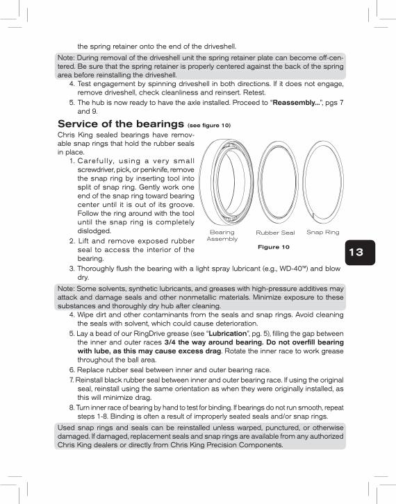
Service of the bearings (see fi gure 10)
Chris King sealed bearings have remov-able snap rings that hold the rubber seals in place.
1. Carefu l ly, us ing a very smal l screwdriver, pick, or penknife, remove the snap ring by inserting tool into split of snap ring. Gently work one end of the snap ring toward bearing center until it is out of its groove. Follow the ring around with the tool until the snap ring is completely dislodged.
2. Lift and remove exposed rubber seal to access the interior of the bearing.
3. Thoroughly fl ush the bearing with a light spray lubricant (e.g., WD-40™) and blow dry.
Note: Some solvents, synthetic lubricants, and greases with high-pressure additives may attack and damage seals and other nonmetallic materials. Minimize exposure to these substances and thoroughly dry hub after cleaning.
4. Wipe dirt and other contaminants from the seals and snap rings. Avoid cleaning the seals with solvent, which could cause deterioration.
5. Lay a bead of our RingDrive grease (see “Lubrication”, pg. 5), fi lling the gap between the inner and outer races 3/4 the way around bearing. Do not overfi ll bearing with lube, as this may cause excess drag. Rotate the inner race to work grease throughout the ball area.
6. Replace rubber seal between inner and outer bearing race.7. Reinstall black rubber seal between inner and outer bearing race. If using the original
seal, reinstall using the same orientation as when they were originally installed, as this will minimize drag.
8. Turn inner race of bearing by hand to test for binding. If bearings do not run smooth, repeat steps 1-8. Binding is often a result of improperly seated seals and/or snap rings.
Used snap rings and seals can be reinstalled unless warped, punctured, or otherwise damaged. If damaged, replacement seals and snap rings are available from any authorized Chris King dealers or directly from Chris King Precision Components.
Note: During removal of the driveshell unit the spring retainer plate can become off-cen-tered. Be sure that the spring retainer is properly centered against the back of the spring area before reinstalling the driveshell.
Note: Some solvents, synthetic lubricants, and greases with high-pressure additives may attack and damage seals and other nonmetallic materials. Minimize exposure to these substances and thoroughly dry hub after cleaning.
Used snap rings and seals can be reinstalled unless warped, punctured, or otherwise damaged. If damaged, replacement seals and snap rings are available from any authorized Chris King dealers or directly from Chris King Precision Components.
13
Bearing Assembly
Rubber Seal Snap Ring
Figure 10
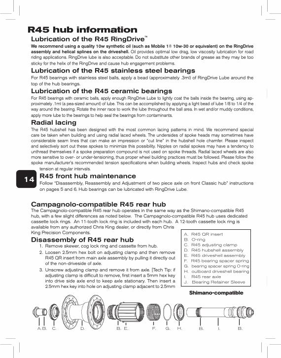
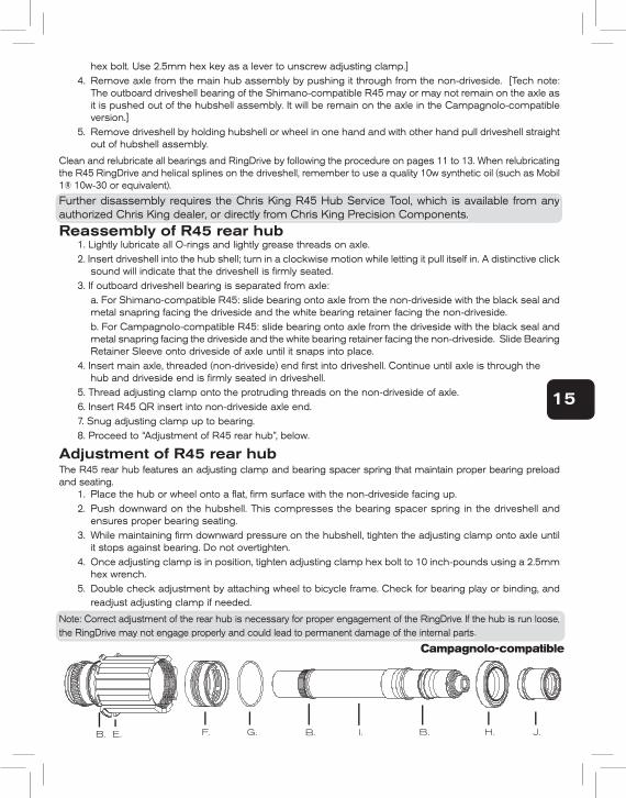
A. R45 QR insertB. O-ringC. R45 adjusting clampD. R45 hubshell assemblyE. R45 driveshell assemblyF. R45 bearing spacer springG. bearing spacer spring O-ringH. outboard driveshell bearingI. R45 rear axleJ. Bearing Retainer Sleeve
R45 hub informationLubrication of the R45 RingDrive™
We recommend using a quality 10w synthetic oil (such as Mobile 1® 10w-30 or equivalent) on the RingDrive assembly and helical splines on the driveshell. Oil provides optimal low drag, low viscosity lubrication for road riding applications. RingDrive lube is also acceptable. Do not substitute other brands of grease as they may be too sticky for the helix of the RingDrive and cause hub engagement problems.
Lubrication of the R45 stainless steel bearings For R45 bearings with stainless steel balls, apply a bead (approximately .3ml) of RingDrive Lube around the top of the hub bearings.
Lubrication of the R45 ceramic bearings For R45 bearings with ceramic balls, apply enough RingDrive Lube to lightly coat the balls inside the bearing, using ap-proximately .1ml (a pea-sized amount) of lube. This can be accomplished by applying a light bead of lube 1/8 to 1/4 of the way around the bearing. Rotate the inner race to work the lube throughout the ball area. In wet and/or muddy conditions, apply more lube to the bearings to help seal the bearings from contaminants.
Radial lacingThe R45 hubshell has been designed with the most common lacing patterns in mind. We recommend special care be taken when building and using radial laced wheels. The undersides of spoke heads may sometimes have considerable seam lines that can make an impression or “cut line” in the hubshell hole chamfer. Please inspect and selectively sort out these spokes to minimize this possibility. Nipples on radial spokes may have a tendency to unthread themselves if a spoke preparation compound is not used on spoke threads. Radial laced wheels are also more sensitive to over- or under-tensioning, thus proper wheel building practices must be followed. Please follow the spoke manufacturer’s recommended tension specifications when building wheels. Inspect hubs and check spoke
tension at regular intervals.
R45 front hub maintenanceFollow “Disassembly, Reassembly and Adjustment of two piece axle on front Classic hub” instructions on pages 5 and 6. Hub bearings can be lubricated with RingDrive Lube.
Campagnolo-compatible R45 rear hubThe Campagnolo-compatible R45 rear hub operates in the same way as the Shimano-compatible R45 hub, with a few slight differences as noted below. The Campagnolo-compatible R45 hub uses dedicated cassette lock rings. An 11-tooth lock ring is included with each hub. A 12-tooth cassette lock ring isavailable from any authorized Chris King dealer, or directly from Chris King Precision Components.
Disassembly of R45 rear hub1. Remove skewer, cog lock ring and cassette from hub. 2. Loosen 2.5mm hex bolt on adjusting clamp and then remove
R45 QR insert from main axle assembly by pulling it directly out of the non-driveside of axle.
3. Unscrew adjusting clamp and remove it from axle. [Tech Tip: if adjusting clamp is difficult to remove, first insert a 5mm hex key into drive side axle end to keep axle stationary. Then insert a 2.5mm hex key into hole on adjusting clamp adjacent to 2.5mm
hex bolt. Use 2.5mm hex key as a lever to unscrew adjusting clamp.]4. Remove axle from the main hub assembly by pushing it through from the non-driveside. [Tech note:
The outboard driveshell bearing of the Shimano-compatible R45 may or may not remain on the axle as it is pushed out of the hubshell assembly. It will be remain on the axle in the Campagnolo-compatible version.]
5. Remove driveshell by holding hubshell or wheel in one hand and with other hand pull driveshell straight out of hubshell assembly.
Clean and relubricate all bearings and RingDrive by following the procedure on pages 11 to 13. When relubricating the R45 RingDrive and helical splines on the driveshell, remember to use a quality 10w synthetic oil (such as Mobil 1® 10w-30 or equivalent).
Further disassembly requires the Chris King R45 Hub Service Tool, which is available from any authorized Chris King dealer, or directly from Chris King Precision Components.
Reassembly of R45 rear hub1. Lightly lubricate all O-rings and lightly grease threads on axle.2. Insert driveshell into the hub shell; turn in a clockwise motion while letting it pull itself in. A distinctive click
sound will indicate that the driveshell is firmly seated.3. If outboard driveshell bearing is separated from axle: a. For Shimano-compatible R45: slide bearing onto axle from the non-driveside with the black seal and
metal snapring facing the driveside and the white bearing retainer facing the non-driveside. b. For Campagnolo-compatible R45: slide bearing onto axle from the driveside with the black seal and
metal snapring facing the driveside and the white bearing retainer facing the non-driveside. Slide Bearing Retainer Sleeve onto driveside of axle until it snaps into place.
4. Insert main axle, threaded (non-driveside) end first into driveshell. Continue until axle is through the hub and driveside end is firmly seated in driveshell.
5. Thread adjusting clamp onto the protruding threads on the non-driveside of axle.6. Insert R45 QR insert into non-driveside axle end.7. Snug adjusting clamp up to bearing.8. Proceed to “Adjustment of R45 rear hub”, below.
Adjustment of R45 rear hubThe R45 rear hub features an adjusting clamp and bearing spacer spring that maintain proper bearing preload and seating.
1. Place the hub or wheel onto a flat, firm surface with the non-driveside facing up.2. Push downward on the hubshell. This compresses the bearing spacer spring in the driveshell and
ensures proper bearing seating.3. While maintaining firm downward pressure on the hubshell, tighten the adjusting clamp onto axle until
it stops against bearing. Do not overtighten.4. Once adjusting clamp is in position, tighten adjusting clamp hex bolt to 10 inch-pounds using a 2.5mm
hex wrench.5. Double check adjustment by attaching wheel to bicycle frame. Check for bearing play or binding, and
readjust adjusting clamp if needed.
Note: Correct adjustment of the rear hub is necessary for proper engagement of the RingDrive. If the hub is run loose, the RingDrive may not engage properly and could lead to permanent damage of the internal parts.
14
A. I.H.G.F.E.D.C.B. B. B.B.
Shimano-compatible
hex bolt. Use 2.5mm hex key as a lever to unscrew adjusting clamp.]4. Remove axle from the main hub assembly by pushing it through from the non-driveside. [Tech note:
The outboard driveshell bearing of the Shimano-compatible R45 may or may not remain on the axle as it is pushed out of the hubshell assembly. It will be remain on the axle in the Campagnolo-compatible version.]
5. Remove driveshell by holding hubshell or wheel in one hand and with other hand pull driveshell straight out of hubshell assembly.
Clean and relubricate all bearings and RingDrive by following the procedure on pages 11 to 13. When relubricating the R45 RingDrive and helical splines on the driveshell, remember to use a quality 10w synthetic oil (such as Mobil 1® 10w-30 or equivalent).
Further disassembly requires the Chris King R45 Hub Service Tool, which is available from any authorized Chris King dealer, or directly from Chris King Precision Components.
Reassembly of R45 rear hub1. Lightly lubricate all O-rings and lightly grease threads on axle.2. Insert driveshell into the hub shell; turn in a clockwise motion while letting it pull itself in. A distinctive click
sound will indicate that the driveshell is fi rmly seated.3. If outboard driveshell bearing is separated from axle: a. For Shimano-compatible R45: slide bearing onto axle from the non-driveside with the black seal and
metal snapring facing the driveside and the white bearing retainer facing the non-driveside. b. For Campagnolo-compatible R45: slide bearing onto axle from the driveside with the black seal and
metal snapring facing the driveside and the white bearing retainer facing the non-driveside. Slide Bearing Retainer Sleeve onto driveside of axle until it snaps into place.
4. Insert main axle, threaded (non-driveside) end fi rst into driveshell. Continue until axle is through the hub and driveside end is fi rmly seated in driveshell.
5. Thread adjusting clamp onto the protruding threads on the non-driveside of axle.6. Insert R45 QR insert into non-driveside axle end.7. Snug adjusting clamp up to bearing.8. Proceed to “Adjustment of R45 rear hub”, below.
Adjustment of R45 rear hubThe R45 rear hub features an adjusting clamp and bearing spacer spring that maintain proper bearing preload and seating.
1. Place the hub or wheel onto a fl at, fi rm surface with the non-driveside facing up.2. Push downward on the hubshell. This compresses the bearing spacer spring in the driveshell and
ensures proper bearing seating.3. While maintaining fi rm downward pressure on the hubshell, tighten the adjusting clamp onto axle until
it stops against bearing. Do not overtighten.4. Once adjusting clamp is in position, tighten adjusting clamp hex bolt to 10 inch-pounds using a 2.5mm
hex wrench.5. Double check adjustment by attaching wheel to bicycle frame. Check for bearing play or binding, and
readjust adjusting clamp if needed.
Note: Correct adjustment of the rear hub is necessary for proper engagement of the RingDrive. If the hub is run loose, the RingDrive may not engage properly and could lead to permanent damage of the internal parts.
Further disassembly requires the Chris King R45 Hub Service Tool, which is available from any authorized Chris King dealer, or directly from Chris King Precision Components.
Note: Correct adjustment of the rear hub is necessary for proper engagement of the RingDrive. If the hub is run loose, the RingDrive may not engage properly and could lead to permanent damage of the internal parts.
15
E.B. G.F. H.B. B.I. J.
Campagnolo-compatible
16
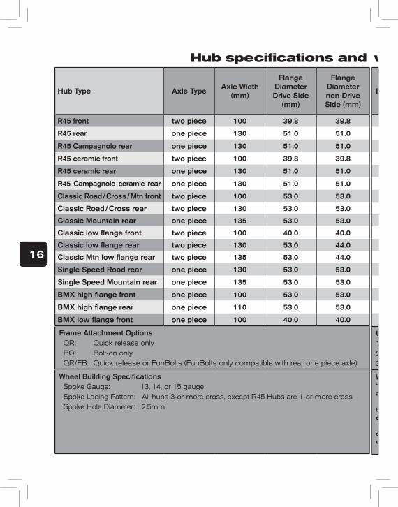
Hub specifications and wheel building information
Hub Type Axle TypeAxle Width
(mm)
Flange Diameter Drive Side
(mm)
Flange Diameter non-Drive Side (mm)
R45 front two piece 100 39.8 39.8
R45 rear one piece 130 51.0 51.0
R45 Campagnolo rear one piece 130 51.0 51.0
R45 ceramic front two piece 100 39.8 39.8
R45 ceramic rear one piece 130 51.0 51.0
R45 Campagnolo ceramic rear one piece 130 51.0 51.0
Classic Road / Cross / Mtn front two piece 100 53.0 53.0
Classic Road / Cross rear two piece 130 53.0 53.0
Classic Mountain rear one piece 135 53.0 53.0
Classic low flange front two piece 100 40.0 40.0
Classic low flange rear two piece 130 53.0 44.0
Classic Mtn low flange rear two piece 135 53.0 44.0
Single Speed Road rear one piece 130 53.0 53.0
Single Speed Mountain rear one piece 135 53.0 53.0
BMX high flange front one piece 100 53.0 53.0
BMX high flange rear one piece 110 53.0 53.0
BMX low flange front one piece 100 40.0 40.0
Frame Attachment Options QR: Quick release only BO: Bolt-on only QR/FB: Quick release or FunBolts (FunBolts only compatible with rear one piece axle)
Wheel Building Specifications Spoke Gauge: 13, 14, or 15 gauge Spoke Lacing Pattern: All hubs 3-or-more cross, except R45 Hubs are 1-or-more cross Spoke Hole Diameter: 2.5mm
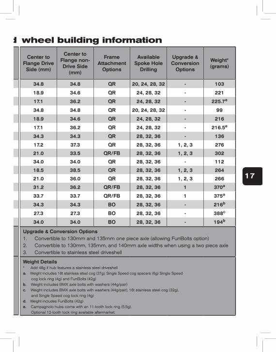
Center to Flange Drive Side (mm)
Center to Flange non-Drive Side
(mm)
Frame Attachment
Options
Available Spoke Hole
Drilling
Upgrade & Conversion
Options
Weight* (grams)
34.8 34.8 QR 20, 24, 28, 32 - 103
18.9 34.6 QR 24, 28, 32 - 221
17.1 36.2 QR 24, 28, 32 - 225.7e
34.8 34.8 QR 20, 24, 28, 32 - 99
18.9 34.6 QR 24, 28, 32 - 216
17.1 36.2 QR 24, 28, 32 - 216.5e
34.3 34.3 QR 28, 32, 36 - 136
17.2 37.3 QR 28, 32, 36 1, 2, 3 276
21.0 33.5 QR/FB 28, 32, 36 1, 2, 3 302
34.0 34.0 QR 28, 32, 36 - 112
18.5 38.5 QR 28, 32, 36 1, 2, 3 264
21.0 36.0 QR 28, 32, 36 1, 2, 3 266
31.2 36.2 QR/FB 28, 32, 36 1 370a
33.7 33.7 QR/FB 28, 32, 36 1 375a
34.3 34.3 BO 28, 32, 36 - 216b
27.3 27.3 BO 28, 32, 36 - 388c
34.0 34.0 BO 28, 32, 36 - 194b
Upgrade & Conversion Options1. Convertible to 130mm and 135mm one piece axle (allowing FunBolts option)2. Convertible to 130mm, 135mm, and 140mm axle widths when using a two piece axle3. Convertible to stainless steel driveshell
Weight Details* Add 48g if hub features a stainless steel driveshella. Weight includes 18t stainless steel cog (37g), Single Speed cog spacers (6g) Single Speed iiiiii iii cog lock ring (4g) and FunBolts (42g)b. Weight includes BMX axle bolts with washers (44g/pair)c. Weight includes BMX axle bolts with washers (44g/pair), 16t stainless steel cog (32g), iiiiiillii and Single Speed cog lock ring (4g)d. Weight includes FunBolts (42g)e. Campagnolo hubs come with an 11-tooth lock ring (5.5g). Optional 12-tooth lock ring available aftermarket.
17
Hub specifications and wheel building information
Hub Type Axle TypeAxle Width
(mm)
Flange Diameter Drive Side
(mm)
Flange Diameter non-Drive Side (mm)
R45 front two piece 100 39.8 39.8
R45 rear one piece 130 51.0 51.0
R45 Campagnolo rear one piece 130 51.0 51.0
R45 ceramic front two piece 100 39.8 39.8
R45 ceramic rear one piece 130 51.0 51.0
R45 Campagnolo ceramic rear one piece 130 51.0 51.0
Classic Road / Cross / Mtn front two piece 100 53.0 53.0
Classic Road / Cross rear two piece 130 53.0 53.0
Classic Mountain rear one piece 135 53.0 53.0
Classic low flange front two piece 100 40.0 40.0
Classic low flange rear two piece 130 53.0 44.0
Classic Mtn low flange rear two piece 135 53.0 44.0
Single Speed Road rear one piece 130 53.0 53.0
Single Speed Mountain rear one piece 135 53.0 53.0
BMX high flange front one piece 100 53.0 53.0
BMX high flange rear one piece 110 53.0 53.0
BMX low flange front one piece 100 40.0 40.0
Frame Attachment Options QR: Quick release only BO: Bolt-on only QR/FB: Quick release or FunBolts (FunBolts only compatible with rear one piece axle)
Wheel Building Specifications Spoke Gauge: 13, 14, or 15 gauge Spoke Lacing Pattern: All hubs 3-or-more cross, except R45 Hubs are 1-or-more cross Spoke Hole Diameter: 2.5mm
Center to Flange Drive Side (mm)
Center to Flange non-Drive Side
(mm)
Frame Attachment
Options
Available Spoke Hole
Drilling
Upgrade & Conversion
Options
Weight* (grams)
34.8 34.8 QR 20, 24, 28, 32 - 103
18.9 34.6 QR 24, 28, 32 - 221
17.1 36.2 QR 24, 28, 32 - 225.7e
34.8 34.8 QR 20, 24, 28, 32 - 99
18.9 34.6 QR 24, 28, 32 - 216
17.1 36.2 QR 24, 28, 32 - 216.5e
34.3 34.3 QR 28, 32, 36 - 136
17.2 37.3 QR 28, 32, 36 1, 2, 3 276
21.0 33.5 QR/FB 28, 32, 36 1, 2, 3 302
34.0 34.0 QR 28, 32, 36 - 112
18.5 38.5 QR 28, 32, 36 1, 2, 3 264
21.0 36.0 QR 28, 32, 36 1, 2, 3 266
31.2 36.2 QR/FB 28, 32, 36 1 370a
33.7 33.7 QR/FB 28, 32, 36 1 375a
34.3 34.3 BO 28, 32, 36 - 216b
27.3 27.3 BO 28, 32, 36 - 388c
34.0 34.0 BO 28, 32, 36 - 194b
Upgrade & Conversion Options1. Convertible to 130mm and 135mm one piece axle (allowing FunBolts option)2. Convertible to 130mm, 135mm, and 140mm axle widths when using a two piece axle3. Convertible to stainless steel driveshell
Weight Details* Add 48g if hub features a stainless steel driveshella. Weight includes 18t stainless steel cog (37g), Single Speed cog spacers (6g) Single Speed iiiiii iii cog lock ring (4g) and FunBolts (42g)b. Weight includes BMX axle bolts with washers (44g/pair)c. Weight includes BMX axle bolts with washers (44g/pair), 16t stainless steel cog (32g), iiiiiillii and Single Speed cog lock ring (4g)d. Weight includes FunBolts (42g)e. Campagnolo hubs come with an 11-tooth lock ring (5.5g). Optional 12-tooth lock ring available aftermarket.
CHRIS KING PRECISION COMPONENTS2801 NW Nela StreetPortland, OR 97210phone: 800.523.6008www.chrisking.comemail: [email protected] rev. 12/26/13-A
Limited WarrantyChris King Precision Components warrants its products to be free from defects in materials or workmanship for the following
periods from the original date of purchase:Headsets: Ten (10) yearsHubs: Five (5) yearsBottom Brackets: Five (5) yearsWheels: The hubs only are warranted for a period of five (5) years. All other wheel components that are not manufactured by
Chris King Precision Components such as, but without limitation, rims, spokes, and nipples, are not warranted by Chris King Precision Components.
Accessories: One (1) yearSoft Goods: Ninety (90) daysAny Chris King product that is found by Chris King Precision Components to be defective in materials or workmanship will be
repaired or replaced at the discretion of Chris King Precision Components. This warranty does not cover damage or failure resulting from misuse, abuse, alteration, neglect, normal and reasonable wear and tear, crash or impact, failure to perform routine maintenance as instructed, improper installation, or use other than that for which the product was intended.
In order to make a warranty claim, the Chris King product alone (i.e., not including any other equipment such as cassettes, skewers, steering tubes, etc.), together with a copy of the original receipt showing the date of purchase of the product, must be returned to Chris King Precision Components at the address set forth on its website (www.chrisking.com) postage prepaid. If a defect is found, our entire liability and your sole remedy shall be, at our option, free repair or replacement of the Chris King product. Chris King Precision Components shall not be held liable for any indirect, special, punitive, or consequential damages. The warranty does not cover any Chris King Precision Components product where the serial number has been altered or removed.
To the fullest extent permitted by applicable law, this written express limited warranty is in lieu of all other warranties, implied or expressed, and does not cover any representation or warranty made by dealers beyond the provisions of this warranty. If any implied warranties exist by applicable law, such implied warranties shall be limited to the duration of the express limited warranty for the product. Some U.S. states and foreign countries provide rights in addition to those above or do not allow the exclusion or limitation of certain warranties or limitation of liability for certain types of damages. Therefore, the above limitations may not apply to you or there may be laws of a state or foreign country which supersede the above. Any clause of this limited warranty or any disclaimer or limitation of liability contained herein that is declared invalid shall be deemed severable and not affect the validity or enforceability of the remaining clauses.
You are strongly encouraged to register your Chris King product on the website within thirty (30) days of the original date of purchase. Registration will assist us in processing your warranty claim and in expediting our response.
All trademarks, registered trademarks, and logos are of their respective holders.©King Cycle Group, 2011. All rights reserved.
Printed with soy ink. Contains 100% post consumer recycled paper fiber.