classical process diagrams and service oriented architecture · classical process diagrams and...
TRANSCRIPT

1023
ACTA UNIVERSITATIS AGRICULTURAE ET SILVICULTURAE MENDELIANAE BRUNENSIS
Volume LXI 113 Number 4, 2013
http://dx.doi.org/10.11118/actaun201361041023
CLASSICAL PROCESS DIAGRAMS AND SERVICE ORIENTED ARCHITECTURE
Milan Mišovič, Ivana Rábová
Received: April 11, 2013
Abstract
MIŠOVIČ MILAN, RÁBOVÁ IVANA: Classical Process diagrams and Service oriented Architecture. Acta Universitatis Agriculturae et Silviculturae Mendelianae Brunensis, 2013, LXI, No. 4, pp. 1023–1032
SOA (Service Oriented Architecture) has played in the last two decades a very useful role in the design philosophy of the target so� ware. The basic units of so� ware for which the mentioned philosophy is valid are called services. Generally it is counted that the advance implementation of services is given by using so–called Web services that are on the platform of the Internet 2.0. Naturally, there has been counted also with the fact that the services will be used in so� ware applications designed by professional programmers. Later, the concept of so� ware services was supported by the enterprise concept of the SOE type (Service oriented Enterprise) and by the creation of the SOA paradigm.Many computer scientists, including Thomas Erl – doyen of SOA, do not understand SOA either as an integrated technology or as a development methodology. Proofs of this statement are in the following defi nitions.SOA is a form of technology architecture that adheres to the principles of service – orientation. When realized through the Web services technology platform, SOA establishes the potential to support and promote these principles throughout the business processes and automation domains of an enterprise (Erl, 2006). Thomas Erl (Erl, 2007) has expressed the idea of SOA implementation using the following defi nition.SOA establishes an architectural model that aides to enhance the effi ciency, agility, and productivity of an enterprise by positioning services as the primary means through which solution logic is represented in support of the realization of strategic goals associated with service-oriented computing. Nevertheless the key principles, on which SOA is constructed (Erl, 2006), are not signifi cantly refl ected in any of the previous defi nitions. Some of the mentioned principles are still included at least in the more free defi nitions of SOA, for example (Barry, 2003).A service-oriented architecture is essentially a collection of services. These services communicate with each other. The communication can involve either simple data or it could two or more services coordinating some activity. From the above mentioned we can pronounce a brief description of SOA. “SOA is an architectural style for consistency of business process logic and service architecture of the target so� ware.”It is a complex of means for solution of special analysis, design, and integration of enterprise applications based on the use of enterprise services. The service solutions of the classic business process logic are, of course, based on the application of at least seven key principles of SOA (free relations, service contract, autonomy, abstraction, reusing, composition, no states). Key attributes of SOA are verbally described in (Erl, 2006). They are so important that a separate article should be devoted to their nature and formalization. On the other hand, there is also clear that each service solution of business logic should respect the principles published in SOA Manifesto, 2009, which are essentially derived from the key principles of SOA.In many publications there are given the SOA reference models usually composed of several layers (presentation layer, business process layer, composite services layer, application layer) giving a meta idea of SOA implementation. Perfect knowledge of the business process logic is a necessary condition for the development of a proper service solution. The diff erent types of business processes should be described in the necessary details and contexts.Interestingly, the SOA paradigm does not provide its own method of fi nding and describing business processes by giving a layered transparent business process diagram. On the other hand, the

1024 Milan Mišovič, Ivana Rábová
methodology provides deep understanding of not only the characteristics of services, but also their functionality and implementation of the key principles of SOA (Erl, 2006).Let us assume that the required process diagrams can be achieved by using some of the advanced methods and descriptions. Among many other methods and description, we can introduce for example methods as Eriksson–Penker Business Extensions, ARIS, BORM (Business Object Relation Modeling) and description as BPMN (Business Process Modeling Notation).This off ers the idea of using these methods and descriptions for the SOA paradigm for the purposes of process models conversion into schemes of services with built-in orchestration. Conversion of transformations should be based on the knowledge of two artifacts. The fi rst is the output artifact – everything what diagram process provides for the target service scheme and the second is the input artifact – all what service schemes need.The issue of conversion transformations is the main topic of this contribution. Their implementation will allow so� ware companies to move forward in the creation of service production and it gives a new view of the enterprise functionality in a service solution to company management.
process, process diagram, enterprise service, SOA (Service oriented Architecture), service orchestration, process diagram conversion
METHODS AND RESOURCES
1 Methods for process diagrams developmentAlready in the abstract we have mentioned
our possible orientation as for three advanced development methods of process diagrams, i.e. Eriksson–Penker Business Extensions, ARIS by prof. Scheer and BPMN. The fi rst two methods, although frequently used, are not accepted as a standard, while the third is the accepted norm under the OMG (Object Management Group) care. Because these methods are widely known we depict only some of their characteristics. We add other properties during the description of the transformation of process diagrams conversion into useful patterns in the SOA paradigm.
2 Eriksson – Penker business ExtensionsIt is an integrated method, detail explained in
(Erik–Penk, 2000), providing four basic views of a business and a collection of graphical or verbal descriptions of diagrams:
Firstly:The strategic view is focused on the description
of the strategic objectives of the company in the production, trade, supply, customer activity and in customer care. The strategic view is fl exibly changed to suit the requirements of a dynamic market. It comprises the company’s vision (needed diagrams: Vision Statement diagram, Conceptual model, Goal model).
Secondly:The process view presents business processes,
their enterprise context, functionality for fulfi llment of corporate vision and mutual respect. The view usually has its layered character and gives context of processes not only in individual layers but also between the layers (needed diagrams: Process Diagram, Assembly Line diagram, Use–Case diagram).
Thirdly:The structural view describes enterprise resources
of diff erent nature, as organizational units, products, documents, information, knowledge, etc. (needed diagrams: Resource Model, Organization Model and Information Model).
Fourthly:The view of the conduct of a company includes the
interaction of individual elements of the enterprise (resources and processes) and responsibility for the corporate elements (needed diagrams: Statechart Diagram, Sequence Diagram and Collaboration Diagram, System Topology diagram).
Within these views, stereotypes and constraints are designed (processes, resources, procedural rules and objectives) and numerous graphic diagrams containing some unusual graphical notation (outside UML).
Process diagram is a unifying diagram for the whole collection of diagrams, because it binds elements of other diagrams (goals, inputs, outputs, resources, support objects, control objects).
The following example shows the strategic goal of a particular company and some fragment of its layered process diagram with two layers. We are going to use this diagram also for its conversion into the scheme of services in the SOA paradigm.
Example 1The main objective of our company, we are
interested in, are mediation group discounts for customer services and consultancy in the fi eld of optimization of costs for various customer services for households. Among mediated customer services there are included mobile services operators, car insurance and energy.
The company business has been identifi ed by fi ve fundamental processes that form the backbone of enterprise functionality as to the main objective of business, which is profi t. They are:• Questionnaire Survey

Classical Process diagrams and Service oriented Architecture 1025
• Administration orders• Targeted range of customer services• Activation of customer service by supplier• Technical support of customer services.
2.1 Process diagrams properties Properties of the process diagram can be seen
in multiple views. At fi rst sight, we can focus on the properties of any process layer. In the second view, we can assume the existence of several layers of the process, from high starting abstraction with the highest layer and ending at the lowest layer. Processes of the higher layer are decomposed
1: Process diagram. Scheme of the main enterprise processes, according to Eriksson–Penker process Extensions method. Taken from (Tom, 2012).

1026 Milan Mišovič, Ivana Rábová
into processes in the lower layer on the basis of decomposition rules. The third view can consist of diagram properties that can aff ect the conversion of process diagram into a platform of enterprise services.
Assume that the process diagram is hierarchical in its nature and it will have a maximum of three layers. Be vi marking one of the process diagram layers, 1 ≤ i ≤ 3. Be pj
(i) the j-th process of the layer vi. Furthermore, be r, s and, t numbers of processes of the fi rst (top), the second and third layer.
On this basis, notations of all layers can be formalized into the following equations:
v1 = ( p1(1), p2
(1), …, pr(1))
v2 = ( p1(2), p2
(2), …, ps(2))
v3 = ( p1(3), p2
(3), …, pt(3)).
Processes in the vi layer have wide context and associations. Each process pj
(i) has input variables {inputs, process rules, events, supply, sourceinp} and publishes output variables {outputs, goals, sourceout}. These variables are not all the possible contextual variables. Based on these variables, there is organized the context to other processes of the given layer and enterprise environment. On the
Administration orders:
2: Decomposition of Administration orders. Taken from (Tom, 2012).

Classical Process diagrams and Service oriented Architecture 1027
basis of the values of these variables, we can produce for pj
(i) the following collection of sets:
{I(i,j), R(i,j), Sin(i,j), E(i,j)},
whereI(i,j) .......the set of inputs variablesR(i,j) ......the set of process rulesSin
(i,j) ....the set of sourcein variablesE(i,j) ......the set of events
{O(i,j), G(i,j), Sout(i,j)},
whereO(i,j) ......the set of outputs variables G(i,j) .....the set of goalsSout
(i,j) ...the set of sourceout variables. The above mentioned sets’ position is illustrated
by the Fig. 3.
Both sets of the input and output variables will be used for the conversion of the process pj
(i) to the service sj
(i) in the third view of the process diagram. Among other things, the sets {I(i,j), R(i,j), Sin
(i,j), E(i,j)}, {O(i,j), G(i,j), Sout
(i,j)} can be used to defi ne one of the factors for assessing the quality Q of the layer vi. For example, such quality (mightiness) may be defi ned by the following regulations
Q =∑|A|, A{I(i,j), R(i,j), Sin(i,j), E(i,j) } {O(i,j), G(i,j), Sout
(i,j)}.
The decompositions of processes of the higher layer vi into fi ner processes in the lower layer vi +1
are part of the compositional point of view. There is necessary to draw up decomposition rules for the fi rst and second layer. Both rules will be used for the introduction of new composite services. Decomposition rules are compiled primarily for specifi c process diagrams. For example, in the fi rst layer in Example 1 the Order Management process is degraded according to the next rule:
Order management == Order acceptance, Order activation,
Order processing, Customer registration).
In the third point of view we are primarily interested in properties of the two previous views that aff ect the conversion processes into enterprise services. Let us choose process mapping into
services of the type 1:1. Then we consider the set {I(i,j), R(i,j), Sin
(i,j), E(i,j) } of the process pj(i) as the basis for
the desired interface of the resulting service sj(i) and
the set {O(i,j), G(i,j), Sout(i,j)} as an off ered interface basis
again. If the process pj(i) is decomposed into fi ner
processes at a lower level, the service sj(i) will be of
a composite type.
2.2 Conversion of Eriksson–Penker Process diagram to Enterprise service platform
Process modeling begins by the highest level of enterprise processes. In Example 1, it is the level composed of the processes Administration orders, Activation of customer services, Technical support, Questionnaire Survey, Targeted range of customer services.
Now we describe relevant conversion steps.
The fi rst step:a) Processes pj
(1) of the highest layer produce the highest composite service X. We carry out relevant mapping (j = 1, 2, …, r) pj
(1) sj(1). We
have just converted this highest layer process diagram to enterprise services and used process names for the names of the new defi ned service units.
b) We defi ne two sets {I(i,j), R(i,j), Sin(i,j), E(i,j)}, {O(i,j), G(i,j),
Sout(i,j)} for each process pj
(1). c) We defi ne the required and provided interface
for all new services sj(1).
d) We will transfer links between processes pj(1) to
the links between business services and construct the resulting graphical orchestration scheme.
e) We replenish the service orchestration diagram in the topmost layer with a sequential diagram to express the functionality of components. We will use the previous results and analysis of the roles of individual actors in the fi rst layer.
Example 2We carry out the fi rst step for all modules of
enterprise services at the fi rst layer. Furthermore, we fi nd links between enterprise services.Based on information from the yet converted fi rst level process model we can already draw a diagram of enterprise service collaboration on the fi rst level with the off ered and required interfaces.
For example, the service Questionnaire survey has its interface as follows:
Required: Surveyed area of customer services, Customer telephone number
Internal rules callOff ered: Statistics success of telephonists Relevant information about the surveyed persons Completed questionnaire Customer telephone number
Service orchestration of the fi rst layer should be added by a transparent sequence diagram (see Fig. 4). The fi rst layer of potential participants selects three actors Telephonist, Customer and Potential
pj(i)
O(i,j) G(i,j) Sout(i,j)
I(i,j) R(i,j) Sin(i,j) E(i,j)
3: Process pj(j) and the list of sets

1028 Milan Mišovič, Ivana Rábová
Customer. We are going to build a strategy on these actors for managing communication services using messages and the interfaces between them.
The second step:a) Further in the scheme of a service orchestration
from the fi rst layer we notice composite services only.
b) Be sj(1) a composite service. This service is
connected in the lower layer with a collection of daughter services. We identify an interface and relationships between these daughter services. On this basis we can construct for each mother service a service schema of the internal orchestration of its daughter services. In addition,
Target range of customerservices
Questionnaire Survey
Technical support ofcustomer services
Activation of customerservice by supplier
Administration orders
The highest compositeservice X<<service>>
<<service>>
<<service>>
<<service>>
<<service>>
4: Orchestration scheme of business services at the first layer
Technical support ofcustomer services
Activation of customerservice by supplier
Administrationorder
Telephonist
Potentialcustomer
Customer
1 2 3
4
5
6
Targeted rangeof customer services
7
8
QuestionnaireSurvey
1 ...... Initiate of service order () 2 ...... Create of service order () 3 ...... Activation of ordered service () 4 ...... Give result information about target range () 5 ...... Technical support for ordered service () 6 ...... Results of questionnaire research () 7 ...... Give result information about target range () 8 ...... Continue of questionnaire research ()
5: Sequence diagram to the orchestration scheme of business services at the first layer

Classical Process diagrams and Service oriented Architecture 1029
we construct a sequence diagram to express the functionality of the mother composite services.
The third step:a) We apply the procedure essence of the fi rst and
the second step between the fi rst and second layer to the second and third layer. So we get service orchestration diagrams at the lowest layer.
b) We carry out check of the completed conversion of process diagram into orchestrations schemas with business services.
Example 3We illustrate the essence of the second step on
the case of one the fi rst-level business service. For example the enterprise service Administration orders consists of the following daughter services: Order acceptance (A), Order activation (B), Order processing (C), Customer registration (D), Contract recording (E). Now we draw the working composition pattern of daughter component services at the second level.
For these fi ve daughter services there is constructed at the second level a process diagram, to which we apply the steps very similar to the steps for the fi rst level. The result is fi nding interfaces and bindings among services. We will add all this
information to the working composition pattern and get a daughter service orchestration of the mentioned parent service.
3 ARIS process diagrams ARIS Method, designed by prof. A.W. Scheer is
an integrated development methodology rather than a method. It is based on fi ve diff erent views (organization, data, functional, procedural, and power), similar to the method of Eriksson–Penker. Its view of the enterprise, however, is broader and the process diagram has stronger context, too. Using the system of diagrams the ARIS methodology provides an interdependent analysis and enterprise design. Due to similar processes in the context of business environment in the process diagram according to the method Eriksson–Penker, we do not get a new piece of signifi cant knowledge in the conversion transformations. For this reason, we will not deal with the conversion transformations of the process diagram by ARIS.
4 BPMN process diagram and its conversion to SOA paradigm
BPMN (Business Process Modeling Notation) is a language standard of the type BPM (Business Process Modeling) of the organization OMG (Object Management Group) for graphical and formal description of business processes. Graphic language elements are divided into several categories (fl ow objects, connecting objects, tracks and artifacts), in which there are further diversifi cations. The semantics of BPMN graphical elements is very similar to semantics of suitable items in other known languages, especially in the UML.
The issue of conversion of the BPMN process diagram to the paradigm of SOA has been successfully addressed (Rychlý–Weiss, 2008). The authors used the conversion method of graphic
Administration orders
A
DC
B
E
6: Working composition pattern of daughter component services
Customer registrationAcceptance of order
Contract recording
Order processing
Order activation
<<service>> <<service>>
<<service>>
<<service>>
<<service>>
7: Orchestration scheme of business services at the second layer

1030 Milan Mišovič, Ivana Rábová
design constructions, of which the BPMN diagram consists, to the target graphic notations in the SOA paradigm. First conversion rules will focus on the basic elements of the BPMN diagram and then on the graphic design elements. Classical sequences, branching and looping (repeat, while) are considered as the graphic design elements.
Identifi cation of candidate services with a comprehensive view of the BPMN diagram is performed before conversion transformations. Tasks, processes and sub–processes are converted into primitive and composite services. Each service is described by a unique specifi cation consisting of behavior and architecture. Behavior describes the
action to be performed and architecture defi nes the communication protocol of services (interfaces and ports). The conversion method is complicated and we will not specify its details. The specifi c example of the BPMN diagram transfer in the SOA paradigm can illuminate many problems.
Example 4The following example of the BPMN diagram
was by authors of the conversion method adapted from Object Management Group, 2006 b. According to the diagram, the process “Purchase Order” is composed of the processes Invoicing, Shipping, and Scheduling. The authors’ conversion method
8: BPMN diagram of the “Purchase Order” process. Taken from (Rychlý–Weiss, 2008).
9: Scheme of identified services with interfaces and connections. Taken from (Rychlý–Weiss, 2008).
Classical Process diagrams and Service oriented Architecture 1031
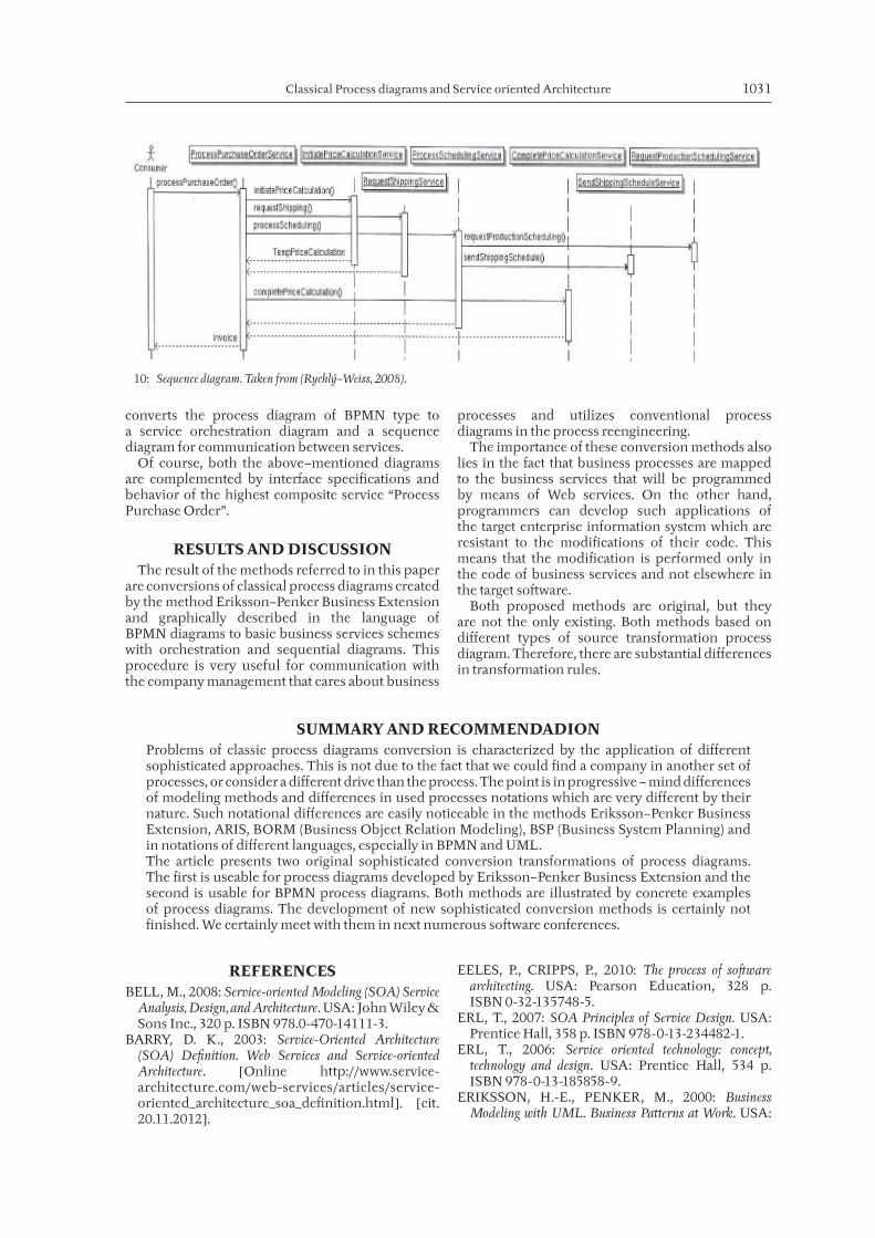
converts the process diagram of BPMN type to a service orchestration diagram and a sequence diagram for communication between services.
Of course, both the above–mentioned diagrams are complemented by interface specifi cations and behavior of the highest composite service “Process Purchase Order”.
RESULTS AND DISCUSSION The result of the methods referred to in this paper
are conversions of classical process diagrams created by the method Eriksson–Penker Business Extension and graphically described in the language of BPMN diagrams to basic business services schemes with orchestration and sequential diagrams. This procedure is very useful for communication with the company management that cares about business
processes and utilizes conventional process diagrams in the process reengineering.
The importance of these conversion methods also lies in the fact that business processes are mapped to the business services that will be programmed by means of Web services. On the other hand, programmers can develop such applications of the target enterprise information system which are resistant to the modifi cations of their code. This means that the modifi cation is performed only in the code of business services and not elsewhere in the target so� ware.
Both proposed methods are original, but they are not the only existing. Both methods based on diff erent types of source transformation process diagram. Therefore, there are substantial diff erences in transformation rules.
10: Sequence diagram. Taken from (Rychlý–Weiss, 2008).
SUMMARY AND RECOMMENDADIONProblems of classic process diagrams conversion is characterized by the application of diff erent sophisticated approaches. This is not due to the fact that we could fi nd a company in another set of processes, or consider a diff erent drive than the process. The point is in progressive – mind diff erences of modeling methods and diff erences in used processes notations which are very diff erent by their nature. Such notational diff erences are easily noticeable in the methods Eriksson–Penker Business Extension, ARIS, BORM (Business Object Relation Modeling), BSP (Business System Planning) and in notations of diff erent languages, especially in BPMN and UML.The article presents two original sophisticated conversion transformations of process diagrams. The fi rst is useable for process diagrams developed by Eriksson–Penker Business Extension and the second is usable for BPMN process diagrams. Both methods are illustrated by concrete examples of process diagrams. The development of new sophisticated conversion methods is certainly not fi nished. We certainly meet with them in next numerous so� ware conferences.
REFERENCESBELL, M., 2008: Service-oriented Modeling (SOA) Service
Analysis, Design, and Architecture. USA: John Wiley & Sons Inc., 320 p. ISBN 978.0-470-14111-3.
BARRY, D. K., 2003: Service-Oriented Architecture (SOA) Defi nition. Web Services and Service-oriented Architecture. [Online http://www.service-architecture.com/web-services/articles/service-oriented_architecture_soa_defi nition.html]. [cit. 20.11.2012].
EELES, P., CRIPPS, P., 2010: The process of so� ware architecting. USA: Pearson Education, 328 p. ISBN 0-32-135748-5.
ERL, T., 2007: SOA Principles of Service Design. USA: Prentice Hall, 358 p. ISBN 978-0-13-234482-1.
ERL, T., 2006: Service oriented technology: concept, technology and design. USA: Prentice Hall, 534 p. ISBN 978-0-13-185858-9.
ERIKSSON, H.-E., PENKER, M., 2000: Business Modeling with UML. Business Patterns at Work. USA:

1032 Milan Mišovič, Ivana Rábová
John Wiley & Sons, Inc., 459 p. ISBN 0-471-29551-5.
LHOTKA, P., ROCKFORD, J., 2009: SOA Manifesto. Lockford – Lhotka Homepage. [Online http://.lhotka.net/weblog/SOAManifesto.aspx]. [cit. 21.11.2012].
MIŠOVIČ, M., 2007: Application Architectures of Enterprise Information Systems versus Service Oriented Architecture. Acta univ. agric. et silvic. Mendel. Brun., 55, 6: 233–242. ISSN 1211-8516.
Object Management Group, 2006 b: UML profi le and meta-model for services (UPMS), request for proposal. Document SOA/2006-09-09. The OMG, Needham, USA. Online http://www.uml.org/ [cit. 25.11.2012].
RYCHLÝ, M., WEISS, P., 2008: Modeling of Service-oriented Architecture: From Business process to Service realization. Third International conference on Evaluation of Novel Approaches to So� ware Engineering Proceedings. Poland: Institute for Systems and Technologies of information, Control and Communication, 12 p. ISBN 978-989-8111-28-9.
TOMÁŠŮ, M., 2012: Modelování podnikové procesní architektury a návrh struktury komponent informačního systému v oblasti služeb. Diplomová práce. Brno: Mendelova univerzita, Provozně ekonomická fakulta, Ústav informatiky.
WOODS, D., MATTERN, T., 2006: Enterprise SOA. Designing IT for Business Innovation. 1st ed. USA: O’Reilly®, 433 p. ISBN 0-596-10238-0.
Address
prof. RNDr. Milan Mišovič, CSc., doc. Ing. Ivana Rábová, CSc., Department of Informatics, Mendel University in Brno, Zemědělská 1, 613 00 Brno, Czech Republic, e-mail: [email protected], [email protected]