slide 13.1 object-oriented and classical software...
TRANSCRIPT

Slide 13.1
© The McGraw-Hill Companies, 2007
Object-Oriented andClassical Software
Engineering
Seventh Edition, WCB/McGraw-Hill, 2007
Stephen R. [email protected]

Slide 13.2
© The McGraw-Hill Companies, 2007
CHAPTER 13
DESIGN

Slide 13.3
© The McGraw-Hill Companies, 2007
Overview
Design and abstraction Operation-oriented design Data flow analysis Transaction analysis Data-oriented design Object-oriented design Object-oriented design: The elevator problem case
study Object-oriented design: The MSG Foundation
case study

Slide 13.4
© The McGraw-Hill Companies, 2007
Overview (contd)
The design workflow The test workflow: Design Formal techniques for detailed design Real-time design techniques CASE tools for design Metrics for design Challenges of the design workflow

Slide 13.5
© The McGraw-Hill Companies, 2007
Data and Actions
Two aspects of a productActions that operate on dataData on which actions operate
The two basic ways of designing a productOperation-oriented designData-oriented design
Third wayHybrid methodsFor example, object-oriented design

Slide 13.6
© The McGraw-Hill Companies, 2007
13.1 Design and Abstraction
Classical design activitiesArchitectural designDetailed designDesign testing
Architectural designInput: SpecificationsOutput: Modular decomposition
Detailed designEach module is designed
Specific algorithms, data structures

Slide 13.7
© The McGraw-Hill Companies, 2007
13.2 Operation-Oriented Design
Data flow analysisUse it with most specification methods (Structured
Systems Analysis here)
Key point: We have detailed action informationfrom the DFD
Figure 13.1

Slide 13.8
© The McGraw-Hill Companies, 2007
Data Flow Analysis
Every product transforms input into output Determine
“Point of highest abstraction of input”“Point of highest abstract of output”
Figure 13.2

Slide 13.9
© The McGraw-Hill Companies, 2007
Data Flow Analysis (contd)
Decompose the product into three modules
Repeat stepwise until each module has highcohesionMinor modifications may be needed to lower the
coupling

Slide 13.10
© The McGraw-Hill Companies, 2007
13.3.1 Mini Case Study: Word Counting
Example:Design a product which takes as input a file name, andreturns the number of words in that file (like UNIX wc )
Figure 13.3

Slide 13.11
© The McGraw-Hill Companies, 2007
Mini Case Study: Word Counting (contd)
First refinement
Now refine the two modules of communicationalcohesion
Figure 13.4

Slide 13.12
© The McGraw-Hill Companies, 2007
Second refinement
All eight modules now have functional cohesion
Mini Case Study: Word Counting (contd)
Figure 13.5

Slide 13.13
© The McGraw-Hill Companies, 2007
Word Counting: Detailed Design
The architectural design is completeSo proceed to the detailed design
Two formats for representing the detailed design:TabularPseudocode (PDL — program design language)

Slide 13.14
© The McGraw-Hill Companies, 2007
Detailed Design: Tabular Format
Figure 13.6(a)

Slide 13.15
© The McGraw-Hill Companies, 2007
Detailed Design: Tabular Format (contd)
Figure 13.6(b)

Slide 13.16
© The McGraw-Hill Companies, 2007
Detailed Design: Tabular Format (contd)
Figure 13.6(c)

Slide 13.17
© The McGraw-Hill Companies, 2007
Detailed Design: Tabular Format (contd)
Figure 13.6(d)

Slide 13.18
© The McGraw-Hill Companies, 2007
Detailed Design: PDL Format
Figure 13.7

Slide 13.19
© The McGraw-Hill Companies, 2007
13.3.2 Data Flow Analysis Extensions
In real-world products, there isMore than one input stream, andMore than one output stream

Slide 13.20
© The McGraw-Hill Companies, 2007
Data Flow Analysis Extensions (contd)
Find the point of highest abstraction for each stream
Continue until each module has high cohesionAdjust the coupling if needed
Figure 13.8

Slide 13.21
© The McGraw-Hill Companies, 2007
13.4 Transaction Analysis
DFA is poor for transaction processing productsExample: ATM (automated teller machine)
Figure 13.9

Slide 13.22
© The McGraw-Hill Companies, 2007
Transaction Analysis (contd)
This is a poor designThere is logical cohesion and control coupling

Slide 13.23
© The McGraw-Hill Companies, 2007
Corrected Design Using Transaction Analysis
Softwarereuse
Have onegeneric editmodule, onegeneric updatemodule
Instantiatethem 5 times
Figure 13.10

Slide 13.24
© The McGraw-Hill Companies, 2007
13.5 Data-Oriented Design
Basic principleThe structure of a product must conform to the structure
of its data
Three very similar methodsMichael Jackson [1975], Warnier [1976], Orr [1981]
Data-oriented designHas never been as popular as action-oriented designWith the rise of OOD, data-oriented design has largely
fallen out of fashion

Slide 13.25
© The McGraw-Hill Companies, 2007
13.6 Object-Oriented Design (OOD)
AimDesign the product in terms of the classes extracted
during OOA
If we are using a language without inheritance(e.g., C, Ada 83)Use abstract data type design
If we are using a language without a typestatement (e.g., FORTRAN, COBOL)Use data encapsulation

Slide 13.26
© The McGraw-Hill Companies, 2007
Object-Oriented Design Steps
OOD consists of two steps:
Step 1. Complete the class diagramDetermine the formats of the attributesAssign each method, either to a class or to a client that
sends a message to an object of that class
Step 2. Perform the detailed design

Slide 13.27
© The McGraw-Hill Companies, 2007
Object-Oriented Design Steps (contd)
Step 1. Complete the class diagramThe formats of the attributes can be directly deduced
from the analysis artifacts
Example: DatesU.S. format (mm/mm/yyyy)European format (dd/mm/yyyy)In both instances, 10 characters are needed
The formats could be added during analysisTo minimize rework, never add an item to a UML
diagram until strictly necessary

Slide 13.28
© The McGraw-Hill Companies, 2007
Object-Oriented Design Steps (contd)
Step 1. Complete the class diagramAssign each method, either to a class or to a client that
sends a message to an object of that class
Principle A: Information hiding
Principle B: If an operation is invoked by manyclients of an object, assign the method to theobject, not the clients
Principle C: Responsibility-driven design

Slide 13.29
© The McGraw-Hill Companies, 2007
13.7 Object-Oriented Design: The Elevator Problem Case Study
Step 1. Complete the class diagram
Consider the second iteration of the CRC card forthe elevator controller

Slide 13.30
© The McGraw-Hill Companies, 2007
OOD: Elevator Problem Case Study (contd)
CRC card
Figure 12.9 (again)

Slide 13.31
© The McGraw-Hill Companies, 2007
OOD: Elevator Problem Case Study (contd)
Responsibilities8. Start timer10. Check requests, and11. Update requests
are assigned to the elevator controller
Because they are carried out by the elevatorcontroller

Slide 13.32
© The McGraw-Hill Companies, 2007
OOD: Elevator Problem Case Study (contd)
The remaining eight responsibilities have the form“Send a message to another class to tell it do something”
These should be assigned to that other classResponsibility-driven designSafety considerations
Methods open doors, close doors are assigned to classElevator Doors Class
Methods turn off button, turn on button are assigned toclasses Floor Button Class and Elevator ProblemClass

Slide 13.33
© The McGraw-Hill Companies, 2007
Figure 13.11
Detailed Class Diagram: Elevator Problem

Slide 13.34
© The McGraw-Hill Companies, 2007
Detailed Design: Elevator Problem
Detailed designof elevatorEventLoopis constructedfrom thestatechart
Figure 13.12

Slide 13.35
© The McGraw-Hill Companies, 2007
13.8 Object-Oriented Design: The MSG Foundation Case Study
Step 1. Complete the class diagram
The final class diagram is shown in the next slideDate Class is needed for C++Java has built-it functions for handling dates

Slide 13.36
© The McGraw-Hill Companies, 2007
Final Class Diagram: MSG Foundation
Figure 13.13
Slide 13.37
© The McGraw-Hill Companies, 2007
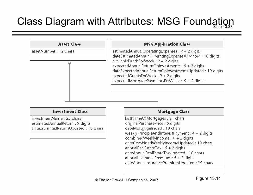
Class Diagram with Attributes: MSG Foundation
Figure 13.14

Slide 13.38
© The McGraw-Hill Companies, 2007
Assigning Methods to Classes: MSG Foundation
Example: setAssetNumber, getAssetNumberFrom the inheritance tree, these accessor/mutator
methods should be assigned to Asset ClassSo that they can be inherited by both subclasses of
Asset Class (Investment Class and Mortgage Class)
Figure 13.15

Slide 13.39
© The McGraw-Hill Companies, 2007
Assigning Methods to Classes: MSG Foundation (contd)
Assigning the other methods is equallystraightforwardSee Appendix G

Slide 13.40
© The McGraw-Hill Companies, 2007
Detailed Design: MSG Foundation
Determine what each method does
Represent the detailed design in an appropriateformatPDL (pseudocode) here

Slide 13.41
© The McGraw-Hill Companies, 2007
Method EstimateFundsForWeek::computeEstimatedFunds
Figure 13.16

Slide 13.42
© The McGraw-Hill Companies, 2007
Method Mortgage::totalWeeklyNetPayments
Figure 13.17

Slide 13.43
© The McGraw-Hill Companies, 2007
13.9 The Design Workflow
Summary of the design workflow:The analysis workflow artifacts are iterated and
integrated until the programmers can utilize them
Decisions to be made include:Implementation languageReusePortability

Slide 13.44
© The McGraw-Hill Companies, 2007
The Design Workflow (contd)
The idea of decomposing a large workflow intoindependent smaller workflows (packages) iscarried forward to the design workflow
The objective is to break up the upcomingimplementation workflow into manageable piecesSubsystems
It does not make sense to break up the MSGFoundation case study into subsystems — it is toosmall

Slide 13.45
© The McGraw-Hill Companies, 2007
The Design Workflow (contd)
Why the product is broken into subsystems:
It is easier to implement a number of smallersubsystems than one large system
If the subsystems are independent, they can beimplemented by programming teams working in parallel The software product as a whole can then be delivered sooner

Slide 13.46
© The McGraw-Hill Companies, 2007
The Design Workflow (contd)
The architecture of a software product includesThe various componentsHow they fit togetherThe allocation of components to subsystems
The task of designing the architecture isspecializedIt is performed by a software architect

Slide 13.47
© The McGraw-Hill Companies, 2007
The Design Workflow (contd)
The architect needs to make trade-offsEvery software product must satisfy its functional
requirements (the use cases)It also must satisfy its nonfunctional requirements,
including Portability, reliability, robustness, maintainability, and security
It must do all these things within budget and timeconstraints
The architect must assist the client by laying outthe trade-offs

Slide 13.48
© The McGraw-Hill Companies, 2007
The Design Workflow (contd)
It is usually impossible to satisfy all therequirements, functional and nonfunctional, withinthe cost and time constraintsSome sort of compromises have to be made
The client has toRelax some of the requirements;Increase the budget; and/orMove the delivery deadline

Slide 13.49
© The McGraw-Hill Companies, 2007
The Design Workflow (contd)
The architecture of a software product is criticalThe requirements workflow can be fixed during the
analysis workflowThe analysis workflow can be fixed during the design
workflowThe design workflow can be fixed during the
implementation workflow
But there is no way to recover from a suboptimalarchitectureThe architecture must immediately be redesigned

Slide 13.50
© The McGraw-Hill Companies, 2007
13.10 The Test Workflow: Design
Design reviews must be performedThe design must correctly reflect the specificationsThe design itself must be correct
Transaction-driven inspectionsEssential for transaction-oriented productsHowever, they are insufficient — specification-driven
inspections are also needed

Slide 13.51
© The McGraw-Hill Companies, 2007
13.11 The Test Workflow: The MSG Foundation Case Study
A design inspection must be performedAll aspects of the design must be checked
Even if no faults are found, the design may bechanged during the implementation workflow

Slide 13.52
© The McGraw-Hill Companies, 2007
13.12 Formal Techniques for Detailed Design
Implementing a complete product and then provingit correct is hard
However, use of formal techniques during detaileddesign can helpCorrectness proving can be applied to module-sized
piecesThe design should have fewer faults if it is developed in
parallel with a correctness proofIf the same programmer does the detailed design and
implementation The programmer will have a positive attitude to the detailed
design This should lead to fewer faults

Slide 13.53
© The McGraw-Hill Companies, 2007
13.13 Real-Time Design Techniques
Difficulties associated with real-time systems
Inputs come from the real world Software has no control over the timing of the inputs
Frequently implemented on distributed software Communications implications Timing issues
Problems of synchronization Race conditions Deadlock (deadly embrace)

Slide 13.54
© The McGraw-Hill Companies, 2007
Real-Time Design Techniques (contd)
The major difficulty in the design of real-timesystemsDetermining whether the timing constraints are met by
the design

Slide 13.55
© The McGraw-Hill Companies, 2007
Real-Time Design Techniques (contd)
Most real-time design methods are extensions ofnon-real-time methods to real-time
We have limited experience in the use of any real-time methods
The state-of-the-art is not where we would like it tobe

Slide 13.56
© The McGraw-Hill Companies, 2007
13.14 CASE Tools for Design
It is critical to check that the design artifactsincorporate all aspects of the analysisTo handle analysis and design artifacts we therefore
need upperCASE tools
UpperCASE toolsAre built around a data dictionaryThey incorporate a consistency checker, andScreen and report generatorsManagement tools are sometimes included, for
Estimating Planning

Slide 13.57
© The McGraw-Hill Companies, 2007
CASE Tools for Design (contd)
Examples of tools for object-oriented designCommercial tools
Software through Pictures IBM Rational Rose Together
Open-source tool ArgoUML

Slide 13.58
© The McGraw-Hill Companies, 2007
13.15 Metrics for Design
Measures of design qualityCohesionCouplingFault statistics
Cyclomatic complexity is problematicData complexity is ignoredIt is not used much with the object-oriented paradigm

Slide 13.59
© The McGraw-Hill Companies, 2007
Metrics for Design (contd)
Metrics have been put forward for the object-oriented paradigmThey have been challenged on both theoretical and
experimental grounds

Slide 13.60
© The McGraw-Hill Companies, 2007
13.16 Challenges of the Design Phase
The design team should not do too muchThe detailed design should not become code
The design team should not do too littleIt is essential for the design team to produce a
complete detailed design

Slide 13.61
© The McGraw-Hill Companies, 2007
Challenges of the Design Phase (contd)
We need to “grow” great designers
Potential great designers must beIdentified,Provided with a formal education,Apprenticed to great designers, andAllowed to interact with other designers
There must be a specific career path for thesedesigners, with appropriate rewards