clearweld® process guidelines for producing seams …
TRANSCRIPT
13436/32/04 JUNE 2004
CLEARWELD® PROCESS GUIDELINES FOR PRODUCING
SEAMS IN FABRICS AND LAMINATES
For: A Group of Collaborators

Copyright © 2004, TWI Ltd TME
CLEARWELD® PROCESS GUIDELINES FOR PRODUCING SEAMS IN FABRICS AND LAMINATES
TWI REPORT NO: 13436/32/04
JUNE 2004
Prepared for: A Group of Collaborators Author: Marcus Warwick

13436/32/04 Copyright © 2004, TWI Ltd
CONTENTS
1. INTRODUCTION 1
1.1. THROUGH-TRANSMISSION LASER WELDING 1
1.2. CLEARWELD® CONCEPT 1
2. CLEARWELD® LASER WELDING 1
2.1. HOW IT WORKS 1
2.2. TECHNICAL FACTORS 2
2.3. WELDING PROCESS 2
2.4. PROCESS PARAMETERS 3
2.5. ADVANTAGES AND LIMITATIONS 6
3. CLEARWELD® ABSORPTIVE MATERIAL SYSTEMS 6
3.1. OVERVIEW 6
3.2. METHODS OF APPLICATION 7
3.3. SPRAY 7
3.4. GUIDELINES FOR SPRAYING 8
3.5. OTHER APPLICATION METHODS 9
4. CLAMPING 10
4.1. TRANSPARENT COVER SHEET 11
4.2. OTHER CLAMPING TECHNIQUES 11
5. HEATING OF TEXTILES 12
5.1. LASER TECHNOLOGIES 12
5.2. TYPES OF LASERS BEST SUITED FOR CLEARWELD® 12
5.3. BEAM CORRECTION METHODS 13
5.4. LASER SAFETY CLASSIFICATIONS 15
6. SEAM DESIGN 15
7. CYTOTOXICITY 17
7.1. TEST NUMBER 1 17
7.2. TEST NUMBER 2 18
7.3. TEST NUMBER 3 18
8. TROUBLESHOOTING 20
8.1. WELDING 20
8.2. SPRAY DISPENSING 22

13436/32/04 Copyright © 2004, TWI Ltd
9. DEFINITIONS 23
10. ACKNOWLEDGEMENTS 24

13436/32/04 Copyright © 2004, TWI Ltd
i
EXECUTIVE SUMMARY
This report summarises, in the form of a set of process guidelines, the results of the research carried out within the LASPET collaborative project. It draws out general lessons learned about joining of textiles using the Clearweld® process, rather than discussing results achieved with specific textiles or applications. The report is divided into the following main sections: Introduction The basic principles of the process are outlined. Clearweld® Laser Welding The effects of the main process parameters are summarised. Clearweld® Absorptive Material Systems The absorber systems are described, together with details of their application to textile joining. Clamping The requirement for a clamping pressure during welding is described, together with methods by which this can be achieved when joining textiles. Heating of Textiles The types of laser equipment that can be used for textile joining with Clearweld® are reviewed. Seam Design Typical seams that can be fabricated using the Clearweld® process are described. Cytotoxicity Results of toxicity testing that has been carried out on the Clearweld® material are presented. Troubleshooting Guidance is given on resolving potential problems encountered when using Clearweld® to join textiles. Definitions Terms commonly used during discussion of laser welding processes are defined.
13436/32/04 Copyright © 2004, TWI Ltd
1
1. INTRODUCTION
Textiles (including woven and non-woven fabrics and flexible laminates) are joined using a wide variety of techniques. Recent developments in both laser and materials technology now allow the benefits of laser welding to be realised in fields such as garments, shoes, protective wear, inflatable structures, airbags, sails and many other applications. 1.1. THROUGH-TRANSMISSION LASER WELDING
In Through Transmission Laser Welding (TTLW) electromagnetic energy is absorbed and converted into thermal energy. Thermoplastics, including man-made fibres, in their natural state, do not absorb near-infrared (NIR) light. Therefore the high energy of NIR lasers transmits through them. To successfully use lasers for joining textiles, laser light must be absorbed at the joint interface to generate enough heat to produce a weld. This is carried out by adding an infra-red absorber to the assembly, either by dispersing it throughout the lower substrate, or as a layer at the joint. However, the use of broad-spectrum absorbers such as carbon black means that colour is added to the joint. This has therefore severely limited the use of laser welding in applications where the appearance of the joint is important, as is usually the case when joining textiles. 1.2. CLEARWELD® CONCEPT
Clearweld® is a revolutionary process for transmission laser welding clear, coloured and opaque textiles without the addition of unwanted colour. Through the use of proprietary material technologies, Gentex has developed the Clearweld® concept for real-world applications. It is now available as a single, flexible solution for joining synthetic textiles. For guidance on joining rigid plastic parts using Clearweld® please refer to the Clearweld® User Guide, available from the Gentex Corporation. 2. CLEARWELD® LASER WELDING
2.1. HOW IT WORKS
Through years of research Gentex has developed a series of materials capable of powerful absorption in the NIR spectrum while imparting minimal visible colour. The key to the Clearweld® process are material systems incorporating these unique absorbers, formulated to optimise laser welding in a wide variety of textile seams. Simply applying a thin layer of the material system at the seam between two textiles concentrates laser energy at the interface. A localised melt of the textiles results in an instant weld, requiring no cure time. The welding process does not perforate the textiles or mark the surfaces, and the welds have minimal visible colour. The effectiveness of the material system depends upon its compatibility with specific process parameters. The exact formulation needed is chosen by taking into account the materials in the textiles, seam design and process requirements. Critical to the success of the Clearweld® process is the accurate delivery of the absorbing material to the joint interface. Clearweld® material systems are tested and certified for use with specific delivery methods, such as spraying or needle dispensing.
13436/32/04 Copyright © 2004, TWI Ltd
2
2.2. TECHNICAL FACTORS
The Clearweld® process simply requires a laser that will produce sufficient energy, an adequate level of NIR absorption at the seam, and intimate contact at the seam to allow the flow of material to occur. Understanding the following technical factors is vital to successfully implementing Clearweld® in a particular application. Material application – The Clearweld® process depends upon accurate and repeatable application of the NIR absorbing layer at the localised seam. Clearweld® material systems are designed for use with approved delivery methods to assure the success of this process (See Clearweld® Absorptive Material Systems section). Typical methods of application are spraying and needle dispensing. Intimate contact – To obtain intimate contact of the substrates at the weld interface, clamping pressure is required. The amount of pressure depends upon the materials being joined and the surface conditions at the weld interface. This allows sufficient melt flow to weld compatible substrates (See Clamping Pressure section). Heat generation – Diode lasers provide the electromagnetic energy necessary for generating heat. The typical wavelengths employed range from 940nm to 1064nm (Nd:YAG lasers at 1064nm have been proven to work with the Clearweld® process, however extensive research has not been done at this wavelength). Depending upon specific application requirements, a variety of power levels and configurations may be considered. It is critical, however, that the laser wavelength matches the wavelength at which the material system is designed to absorb (See Laser Technologies Section). Key to ensuring a successful Clearweld® implementation are optimisation of laser power, weld speed, pressure and absorption level of the material system. Fine-tuning these parameters can help produce seam strengths and processing speeds equal to or greater than alternative joining techniques. 2.3. WELDING PROCESS
The welding process consists of three stages: • Application of the Clearweld® material system to the textile. • Assembly of the seam and application of clamping pressure. • Irradiation of the seam with a NIR laser to create a permanent weld. These operations can all be automated, and may be combined into a set of integrated equipment – a Clearweld® sewing machine. Application of Clearweld® material system – This process and the equipment used are described in more detail in Section 3. The material system may be applied in the form of a low-viscosity liquid, which dries rapidly to leave a deposit of the Clearweld® material system on the surface of the textile. It may also be deposited on the surface of an interleaving film that is compatible with the textiles to be joined. A third option is to incorporate the Clearweld® material system in a compatible interleaving film.

13436/32/04 Copyright © 2004, TWI Ltd
3
Assembly of the seam – The types of seam that may be produced are described in Section 6, and the methods of applying a suitable clamping pressure are described in Section 4. The seam, including any interleaving film, must be assembled and held in place such that the interface between the textiles can be irradiated through one of the textiles. The assembly must also apply a clamping pressure to the joint during welding, without hindering access of the laser. Irradiation – A NIR laser is used to irradiate the seam. The Clearweld® material system absorbs the laser radiation, concentrating the heat at the interface between the textiles. A thin film of polymer is melted in each textile and the application of clamping pressure brings these films into contact. The pressure is maintained as the films cool and solidify to produce a permanent weld. 2.4. PROCESS PARAMETERS
The key to producing a successful seam is to use the correct process parameters for the textiles being joined. The heat put into the seam must be sufficient to melt enough of the material to accommodate any surface roughness and to form a weld over the whole area, but not so much that the textile is melted through its entire thickness. If insufficient heat is put into the seam then a weak weld will result that pulls apart at the interface between the two textiles. If too much heat is put into a seam then one or both textiles will melt through their full thickness, and a line of weakness will be created at the edge of the weld. (this is what occurs when conventional welding techniques such as hot bar welding or ultrasonic welding are used to produce fabric seams.) In the processing window between these two extremes it is possible to produce seams with high strength and excellent appearance. Fig.1 shows a cross-section through a satisfactory seam in a woven nylon fabric. For comparison, Fig.2 shows a cross section through a seam that did not receive enough heat, and Fig.3 shows a seam that received too much.
Cross-sectionthrough upperfabric
Cross-sectionthrough lowerfabric
Solidifed weldmaterial joiningthe fabrics
Fig.1 Cross section through satisfactory seam.

13436/32/04 Copyright © 2004, TWI Ltd
4
Fig.2 Cross section through seam with insufficient heat.
Fig.3 Cross section through seam with too much heat.

13436/32/04 Copyright © 2004, TWI Ltd
5
The amount of heat put into the seam, per unit area, is determined by four critical parameters: • The transmission properties of the upper textile. • The power density of the laser. • The welding speed. • The quantity of Clearweld® material system at the seam. Transmission properties – The fraction of incident NIR radiation transmitted by the upper fabric must be at least 10% in order for the Clearweld® process to be used successfully. This should not vary significantly from region to region in the textile, for example as a result of a pattern, as this will alter the amount of heat reaching the seam and therefore affect the quality of the seam. Power density – The power density of the laser is determined by the total power of the beam and by the spot size used for welding. As the total power increases, the power density increases in direct proportion, but as the spot size increases, the power density falls in proportion to the square of the spot size. The spot size will usually be determined by the width of seam required, so it is usual to adjust the power density simply by altering the total power. Welding speed – A lower speed will result in more heat going into the seam. It might be expected that with all other parameters kept the same, doubling the laser power and doubling the speed would result in a weld of the same quality. However, when the time dependent conduction of heat away from the seam is considered, theoretical models predict that doubling the power should allow the speed to be increased by a factor of four, and this is borne out by experiment. Clearweld® material system density – To maximise efficiency and to minimise any residual colour in the seam, the minimum amount of Clearweld® material system that will give the required weld should be used. In practice, the textiles, required seam width and minimum required welding speed will often be known, so experimentation will only be required to find the correct Clearweld® material system density and laser power to give a satisfactory weld. Suitable process parameters have been identified for a number of common textile materials – for example polyamides, polyesters and polypropylene – and Gentex can arrange trials or demonstrations as required.
13436/32/04 Copyright © 2004, TWI Ltd
6
2.5. ADVANTAGES AND LIMITATIONS
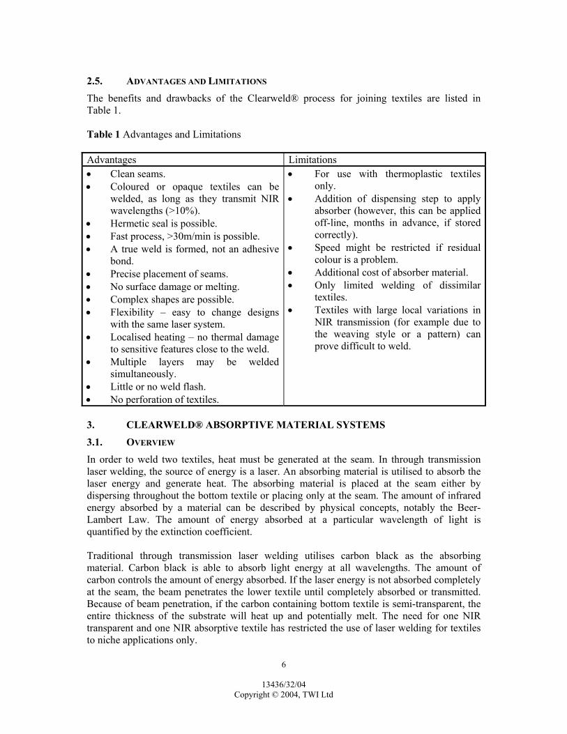
The benefits and drawbacks of the Clearweld® process for joining textiles are listed in Table 1. Table 1 Advantages and Limitations Advantages Limitations • Clean seams. • Coloured or opaque textiles can be
welded, as long as they transmit NIR wavelengths (>10%).
• Hermetic seal is possible. • Fast process, >30m/min is possible. • A true weld is formed, not an adhesive
bond. • Precise placement of seams. • No surface damage or melting. • Complex shapes are possible. • Flexibility – easy to change designs
with the same laser system. • Localised heating – no thermal damage
to sensitive features close to the weld. • Multiple layers may be welded
simultaneously. • Little or no weld flash. • No perforation of textiles.
• For use with thermoplastic textiles only.
• Addition of dispensing step to apply absorber (however, this can be applied off-line, months in advance, if stored correctly).
• Speed might be restricted if residual colour is a problem.
• Additional cost of absorber material. • Only limited welding of dissimilar
textiles. • Textiles with large local variations in
NIR transmission (for example due to the weaving style or a pattern) can prove difficult to weld.
3. CLEARWELD® ABSORPTIVE MATERIAL SYSTEMS
3.1. OVERVIEW
In order to weld two textiles, heat must be generated at the seam. In through transmission laser welding, the source of energy is a laser. An absorbing material is utilised to absorb the laser energy and generate heat. The absorbing material is placed at the seam either by dispersing throughout the bottom textile or placing only at the seam. The amount of infrared energy absorbed by a material can be described by physical concepts, notably the Beer-Lambert Law. The amount of energy absorbed at a particular wavelength of light is quantified by the extinction coefficient. Traditional through transmission laser welding utilises carbon black as the absorbing material. Carbon black is able to absorb light energy at all wavelengths. The amount of carbon controls the amount of energy absorbed. If the laser energy is not absorbed completely at the seam, the beam penetrates the lower textile until completely absorbed or transmitted. Because of beam penetration, if the carbon containing bottom textile is semi-transparent, the entire thickness of the substrate will heat up and potentially melt. The need for one NIR transparent and one NIR absorptive textile has restricted the use of laser welding for textiles to niche applications only.

13436/32/04 Copyright © 2004, TWI Ltd
7
Clearweld® material systems contain complex, organic materials that strongly absorb infrared energy. The absorbers can be selected to optimise absorption at a particular laser wavelength. At present, Gentex offer solutions that are best suited for use in the 940 to 1064nm range. The level of absorption intensity can be modified to best match application requirements. In essence, the Clearweld® material systems are tailored for particular applications. The materials used to absorb laser energy and generate heat are solids. To optimise the absorption of infrared energy at the seam, the material should be deposited in a uniform manner on at least one of the textiles. In order to achieve this uniform deposit the absorbers are dissolved in organic solvent systems and supplied to customers as a chemical solution. The low viscosity solution is deposited or “printed” onto the surface. The solvent flashes off, leaving a thin, consistent layer of material on the surface. 3.2. METHODS OF APPLICATION
Several methods of applying the Clearweld® material systems to textiles exist. In essence, any method that can be used to apply a low-viscosity liquid to a substrate can be used. However, the critical requirements for applying these solvent-based materials include: Consistency – Entire seam area contains the same amount of absorber. Repeatability – Every seam has the same amount of absorber. Lack of contamination – Little or no additives or contaminants to the material system. The absorber is the material that enables a weld to be produced. If application of the absorber is uneven, the weld can overheat in some areas while no weld is formed in other areas. Consistent application is critical for obtaining consistent seam quality and strength. Some application and printing methods require additives such as viscosity enhancers for good print quality. However, additives can reduce weld strength. For this reason application methods suitable for low-viscosity liquids are preferred. The method of application is dependent upon the design of the parts to be coated and the requirements of the end user. In general, a method of application should apply the Clearweld® material system only to the area where a weld is desired. Precise application of the material eliminates the need for a mask during welding. Other factors, such as speed of operation will also affect the choice of application method. 3.3. SPRAY
The most effective technique that has been used to apply Clearweld® material systems to textiles is spraying. In this method of application, the solution is stored in a reservoir. A low pressure is applied to the reservoir and forces the solution to an air cap on a spray gun. Atomising air is introduced into the air cap to disperse the solution from the nozzle as droplets. This system has the advantages of ease of operation and the ability to cover a large area in a single pass. Many spray guns are commercially available. It is recommended that an end user contact a service representative of the gun manufacturer prior to installation. Clearweld® material systems contain solvents that can interact with certain packing materials that are used in spray guns.

13436/32/04 Copyright © 2004, TWI Ltd
8
3.4. GUIDELINES FOR SPRAYING
The spray gun, or the textile, or both, may be moved during the spraying operation. The simplest equipment would consist of a fixed spray gun with a moving web of textile. Alternatively, the spray gun may be attached to a robotic system to apply more complex patterns of the Clearweld® material system to either a stationary or moving textile web. Spray guns typically produce a cone-shaped spray with a circular cross section. As this is passed over a textile it produces a non-uniform concentration profile of the Clearweld® material system across the width of the track. A number of procedures may be used to limit the effects of this concentration profile: Restriction of Irradiated Area – If the laser is set to give a spot size smaller than the width of the Clearweld® material system deposit then producing a seam down the centre of the deposit will give a uniform weld. This can give excellent control of the seam width. Excess material system at the edge of the seam may then be removed by rinsing with an appropriate solvent. Masking – A suitable mask can be used to limit the deposit to the centre of the spray cone. This will produce a uniform deposit. If the laser spot used for welding overlaps the edge of this deposit then the width of the seam will be controlled by the width of the deposit. Raster Pattern – Spraying several parallel tracks with an appropriate offset can give a roughly uniform deposit over a wide area. This technique can be used to prepare wide seams in textiles. Shaped Spray – Additional air jets may be used to shape the cone to give an elongated cross-section. This can then be used to produce a track with a more uniform profile of concentration across its width. However, if two-dimensional patterns are to be prepared then the spray nozzle must be rotated during the spraying process to achieve a uniform concentration profile in all directions of movement. As the Clearweld® material system flow rate to the spray gun is increased, by increasing the pressure applied to the reservoir or by opening the control valve wider, the following effects are seen: • At low flow rates the width of the deposit increases only slowly as the flow rate
increases, giving a steady increase in the density of the material system within the deposit.
• At a critical value of the flow rate, the width of the deposit increases sharply, and the edges of the deposit become wavy rather than straight. This causes the density of the material system within the deposit to decrease.
It is usual to operate a little below the critical value of flow rate to give the highest density of material system, allowing a small margin to give a robust process. If the atomising pressure is too low then relatively large droplets will be produced giving a non-uniform distribution of Clearweld® material system on the surface. If the atomising pressure is too high, or if the spray head is too close to the surface, then the turbulence

13436/32/04 Copyright © 2004, TWI Ltd
9
created when the high air flow strikes the substrate will tend to disperse the spray over a wider, uncontrolled area. In practice, a relatively large operating window can usually be found in which a controlled deposit may be produced. When spraying a non-absorbent textile it may be seen that the atomising air stream blows drops of the Clearweld® material system around on the surface. This is undesirable as coalescence of drops and movement of material on the surface will lead to a non-uniform deposit. If this occurs then it may be necessary to take one or more of the following corrective actions: • Reduce the atomising pressure, taking care to ensure that a uniform deposit is still
produced. • Increase the distance between the spray head and the surface. • Increase the spraying speed and deposit the required density of material system
using a larger number of spray passes. This produces a thinner film in each pass, which will be less susceptible to coalescence.
Spray deposition is the most effective application method for absorbent surfaces (offering a complementary technique to that of needle dispensing, see below). In general, it is preferable to deposit the required amount of Clearweld® material system using several high speed spray passes rather than fewer slow passes. This limits penetration of the material system into the textile and thereby helps to restrict melting during the welding process to the surface only. This avoids melting the full thickness of the textile, retaining the surface appearance and avoiding the introduction of a line of weakness at the edge of the weld. For the same reason, it is preferable to achieve the required density of material system on the textile by using fewer spray passes with a Clearweld® material system of higher concentration. It can be difficult to calibrate the exact quantity of Clearweld® material system applied. It is therefore useful to be able to assess the NIR absorption of a deposit. This can be carried out using a laser, a laser energy meter and a standard fabric. The meter is used to measure the energy of a short laser pulse transmitted by the fabric with and without a sprayed deposit, allowing the absorption by the deposit to be calculated. On a practical note, the fabric should be positioned such that the deposit faces away from the laser, and a low energy pulse should be used. If this is not done then the absorber may degrade during the measurement, confusing the results (if a repeat measurement in the same place shows a decrease in absorption then the absorber is being degraded, and a lower energy pulse should be used). This can be used to ensure consistency of the sprayed deposit following changes to settings on the spray equipment – spray speed and the number of passes used can be adjusted to give a deposit with the required absorption. 3.5. OTHER APPLICATION METHODS
Needle Dispensing – This technique has been extensively used for depositing Clearweld® material systems onto rigid substrates. A constant flow rate of the material system is supplied to a hollow needle dispenser that is traversed over the substrate by an automated robot. This produces a highly reproducible deposit of the material system. The technique is suitable for smooth, non-porous laminate surfaces. Equipment and service support is readily available. EFD Inc., a division of the Nordson Corporation are recommended for your dispensing valve
13436/32/04 Copyright © 2004, TWI Ltd
10
requirements. The Nordson Corporation is also a leading manufacturer of robotic systems and offers a wide range of equipment. They have developed systems that have been certified for use with Clearweld material systems. This technique is unsuitable for applying material systems to rough or absorbent surfaces. Brushing - Brushing of the Clearweld® material systems onto textiles has also been used to create seams. Liquid dispensing equipment can be adapted to use brush tips rather than needles. The same practices used in needle dispensing would apply to brush applicators. Brushing can be used to apply wider lines than normally deposited by liquid dispensing techniques. Felt Tip Applicators – Felt tip applicators have also been successfully used to deposit Clearweld® material systems onto textiles. As in the case of brushing, standard liquid dispense equipment can be adapted to use felt tip applicators. Since the flow through a felt tip would be less than from a needle or a brush, the deposits would be less dense than normal liquid dispensing methods. However, for some applications, this method might provide a more uniform deposit. Dipping – Many tests have been conducted in which the Clearweld® material system was applied by merely dipping a substrate into the solution and allowing the solvent to evaporate. Although this method could be used for textiles, the control of concentration of the absorbing material in the solution would be somewhat difficult. It is therefore not recommended for a production application. Films – Incorporation of the absorbing material into film has also been validated. The film then serves as a carrier for the absorbing material in the welding operation. This method of application would have to be tailored to each end use. At the moment it would not be an “off the shelf” solution to a welding application. 4. CLAMPING
The Clearweld® process, like other welding techniques, requires the two textiles to be joined under pressure. Clamping pressure is required for several reasons, including: • To provide intimate contact between the two surfaces to be welded. Surfaces
typically have asperities (bumps, valleys, etc.) that prevent close contact. As the surfaces heat, the clamping pressure flattens the surfaces and removes entrapped air to impart even contact along the interface.
• To achieve heating and melting in both substrates. The Clearweld® material system is applied only to one textile surface (in most cases). The absorber generates heat as a result of being exposed to laser energy. In order to obtain a weld, both textiles must melt. Intimate contact between the surfaces allows this heating and melting to occur.
• To allow diffusion of polymer chains between the surfaces. A weld is created in plastics by intermingling of the polymer chains from both substrates. When the plastic melts, the polymer chains are able to move. Clamping pressure brings the surfaces in contact to enable diffusion. In addition, the pressure provides the force to push the chains together.
13436/32/04 Copyright © 2004, TWI Ltd
11
• To prevent separation of the textiles during the cooling phase. All materials expand upon heating and contract upon cooling to some degree. Once the laser energy is removed the material begins to cool and the material contracts. If clamping pressure is not applied during cooling, the textiles may separate. The clamping pressure is required to maintain contact between the textiles as the material contracts. When joining most materials using the Clearweld® process, only a small localised region of plastic is melted. The melted plastic cools rapidly, therefore shorter hold times are required.
4.1. TRANSPARENT COVER SHEET
A convenient way to provide clamping pressure between two textiles is to position the seam on a rigid support beneath a sheet of transparent PMMA. This holds the textiles in place and prevents any rucks or wrinkles forming when additional local clamping is provided via a sliding pressure pad or roller. The local clamping should be applied as close as possible to the laser, and deforms the transparent cover sheet, holding the two textiles in intimate contact while the weld is formed. A ring-shaped sliding clamp is typically used to provide local clamping pressure. The laser irradiates the textiles through the hole in the centre of the ring. The ring can be attached to a pneumatic actuator to apply a load to the surface of the cover sheet. Alternatively, rollers may be used to apply a local clamping pressure. For simplicity, a single roller acting as a caster, trailing behind the laser, is most straightforward, but any number of rollers surrounding the beam may be used. At the end of a seam it is important that the local clamping pressure is maintained for long enough for the weld to solidify. Because the Clearweld® process only melts a small amount of material a holding period of about two seconds is usually more than enough. 4.2. OTHER CLAMPING TECHNIQUES
Any method of ensuring intimate contact between the textiles while they are welded will allow a satisfactory seam to be produced. The following techniques have been demonstrated: Vacuum Bag – The seam may be sealed inside a vacuum bag made from a thin film of polymer that is transparent to NIR radiation. The interior of the bag is evacuated using a vacuum pump, allowing atmospheric pressure to clamp the textiles together. The seam is then welded by irradiating the textiles through the bag. Film Tension – Two textiles may be positioned over a roller or convex curved surface with a NIR transmissive polymer film over the top. If the film is then placed under tension then a compressive force is generated between the two textiles, which can be sufficient to generate a weld when the textiles are irradiated. For multilayer laminates this technique may be used without the additional cover film, by applying tension directly to the textile. However, for thinner fabrics or laminates, applying tension to the textile while it is welded can tear it. Laser Sewing Machine – A mechanism similar to a sewing machine can be used to produce a local clamping pressure while a short stretch of seam is irradiated to produce a weld. The mechanism then feeds the two textiles through and clamps the next section of seam. This may
13436/32/04 Copyright © 2004, TWI Ltd
12
be done swiftly enough to produce effectively continuous operation. The same mechanism may also be used to include a tape made from a film containing the Clearweld® material system. This avoids the need for a secondary process to apply the materials system to the textile. 5. HEATING OF TEXTILES
5.1. LASER TECHNOLOGIES
Lasers are available over a broad range of wavelengths, for example: • CO2 – 10,600nm. • Nd:YAG – 1064nm. • Diode – 635-670nm, 808nm, 940nm, 980nm. • Ruby – 644nm. • HeNe – 543nm, 633nm. The beams are either pulsed or continuous wave. 5.2. TYPES OF LASERS BEST SUITED FOR CLEARWELD®
0
0.1
0.2
0.3
0.4
0.5
0.6
0.7
0.8
0.9
1
Wavelength (nm)
Abso
rban
ce
PMMA Only
Clearweld
Absorber + PMMA/No Weld
500400 600 700 800 900 1000 1100
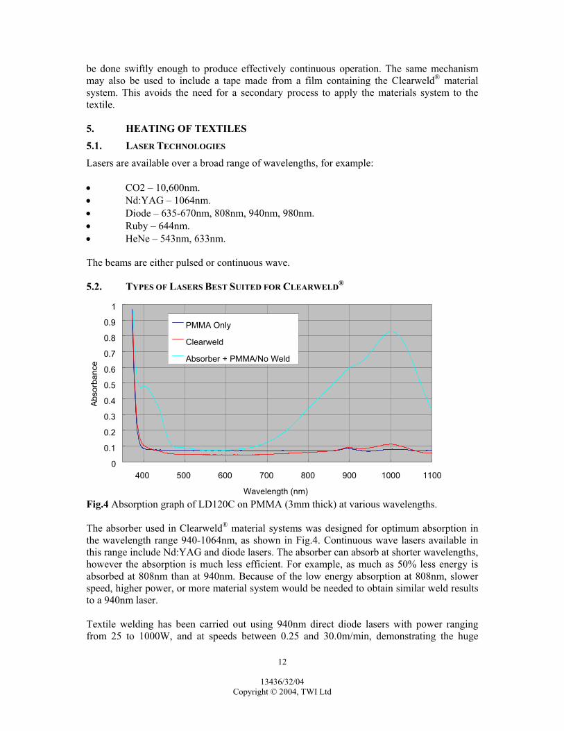
Fig.4 Absorption graph of LD120C on PMMA (3mm thick) at various wavelengths. The absorber used in Clearweld® material systems was designed for optimum absorption in the wavelength range 940-1064nm, as shown in Fig.4. Continuous wave lasers available in this range include Nd:YAG and diode lasers. The absorber can absorb at shorter wavelengths, however the absorption is much less efficient. For example, as much as 50% less energy is absorbed at 808nm than at 940nm. Because of the low energy absorption at 808nm, slower speed, higher power, or more material system would be needed to obtain similar weld results to a 940nm laser. Textile welding has been carried out using 940nm direct diode lasers with power ranging from 25 to 1000W, and at speeds between 0.25 and 30.0m/min, demonstrating the huge

13436/32/04 Copyright © 2004, TWI Ltd
13
flexibility of this process. A high power laser may be needed to achieve a high welding speed particularly because of the relatively low transmission properties of many textiles. However, it should be noted that the purchase and running costs of a laser increase as its maximum power increases. For a cost-effective textile joining process it is therefore important to understand the application requirements and to select appropriate equipment. 5.3. BEAM CORRECTION METHODS
Laser diode bars are rectangular, which results in undesirable beam characteristics. The beam, as it exits the diode, has an elliptical cross-section. The shape of the cross-section may vary from diode to diode. Because of the rectangular facet of the diode, the focal point is different in the x-direction than the y-direction. As a result, a single lens will collimate the beam in one direction only. This phenomenon is called astigmatism. There are two common methods for correcting the beam in order to produce a circular cross-section and reduce astigmatism. The first method is referred to as lens correction, and the second method is referred to as fibre-coupling. Lens Correction – The lens correction method utilises a series of prisms and a lens to correct the beam. The corrected beam shape is square or rectangular. The minimum available beam size is approximately 0.45mm x 0.45mm for a low power laser. The minimum size increases to approximately 1.2mm x 1.2mm for the highest power diode lasers, Changing the focusing lens can increase the beam size. Fibre-coupling – The fibre-coupled method of correcting the beam utilises two lenses to focus the beam in to a single mode fibre (circularises the beam), and a third lens on the output end of the fibre to collimate the beam. The beam is circular and the minimum available beam size is approximately 0.2mm in diameter. The beam size can be increased with different lenses. Table 2 Benefits and drawbacks of different beam correction techniques. Technique Advantages Drawbacks Lens correction
• Easy to use, no special handling. • Low cost.
• High beam distortion – reduction of beam quality.
• Astigmatism – beam not fully collimated, i.e., beam does not converge to a single focal point.
Fibre-coupling
• Small distortion – good beam quality.
• Little residual astigmatism.
• Power loss of 25-30% within the fibre.
• High cost. • Special handling to ensure no
damage to the fibre. The benefits and drawbacks of the different techniques are summarised in Table 2. The main factors in selecting a beam delivery method are power, desired weld quality, and cost. Lens correction methods can output higher powers. Fibre-coupled lasers have better beam quality

13436/32/04 Copyright © 2004, TWI Ltd
14
therefore more uniform welds can be produced. Lens corrected lasers are typically less expensive than fibre-coupled. In general, as the laser power increases the minimum spot size available will also increase. Laser Configurations The laser beam can be directed on to the part by a number of techniques: • Single beam – contour. • Scanning beam. • Curtain. • Simultaneous. Unlike laser welding with an absorptive substrate such as carbon black, the laser beam does not have to be as precise when using Clearweld®. With an absorptive bottom substrate, the laser beam must be precise since heating and melting will occur in all areas that the beam contacts. However with Clearweld®, heating and melting of a textile that is exposed to the laser will only occur where the Clearweld® material interacts with the laser (this makes accurate material application very important). Another point to note is that if the laser beam width is narrower than the printed Clearweld® material line width, residual colour will remain due to unwelded Clearweld® material system adjacent to the weld. This may be removed by rinsing with a suitable solvent. Single Beam – Contour – When welding using a single beam, the laser hits the weld interface as a beam, or point. Moving the part under the beam or moving the beam across the part produces the weld. The part can be moved by a number of means, including a conveyor belt, x-y table, or rotary table. The laser can be moved by attaching it to a robotic arm. High power diode lasers are constructed from stacks of diode arrays, and, when used with lens correction, produce a beam with a rectangular cross-section away from the focal plane. This may be used to control the width of a seam, but the beam must be rotated (either by rotating the head or using special additional optics) to ensure a constant width when seams are prepared in different directions. Scanning Beam – A scanning system also uses a single beam. However a series of mirrors attached to galvanometer motors deflects the beam to the appropriate path. The advantage of this system is that the laser and welded part remain stationary. A scanning system can also be used to scan the beam rapidly to produce a beam with a particular distribution of energy. If a textile seam is passed beneath such a shaped beam then complex seams may be produced. For example, the scanning system might be used to form two spots, allowing two closely spaced parallel seams to be produced. Curtain – A curtain laser system uses a series of laser beams combined side by side, or one or more laser beams spread out by optics, to form a line (or curtain). Either the curtain or the part is moved to expose the weld interface. When a curtain beam is used in traditional through transmission laser welding, a mask is required to weld only in specific areas. A mask is not needed in Clearweld® since welding occurs only where the absorber is applied.

13436/32/04 Copyright © 2004, TWI Ltd
15
Simultaneous – Array – Simultaneous systems consist of a series of laser beams arranged in the shape of the seam to be welded. There are no moving parts, and the entire seam is heated at one time. A comparison of the different configurations is shown in Table 3. Table 3 Comparison of laser configurations. Single beam Scanning Curtain Simultaneous Weld speed, 1=fast, 3=slow 2* 1 2* 1
Flexibility of one set of equipment to weld different seam geometries, 1=high, 3=low
1 1 1 3
Welding of 3-dimensional seams, 1=possible, 2=limited, 3=impossible
1 3† 3† 2
Efficiency, 1=high, 3=low 1 1 3‡ 1
Maximum part size Depends on size of motion equipment
500mm x 500mm with a 10mm beam
Large parts possible but cost may be prohibitive
Large parts possible but cost may be prohibitive
* Speed limited by motion equipment. † Laser beam diverges away from the focal plane. Parts with a large height difference
will cause the beam to hit the seam at different beam sizes, causing variation in energy density.
‡ Large portion of the beam is not used at any given time. 5.4. LASER SAFETY CLASSIFICATIONS
Lasers used for Clearweld® will typically be categorised as Class 4 and appropriate precautions will therefore be required. ANSI Z136.1 provides information to assist users in the designing the proper safety program. For a Clearweld® system this will typically mean remote operation, or at a minimum, suitable screening to prevent inadvertent exposure. 6. SEAM DESIGN
The industrial standard, ASTM D 6193-97, “Standard Practice for Stitches and Seams” covers the requirements and characteristics of stitches and seams in the fabrication of sewn items. It lists 55 types of seam in which the fabrics are superimposed and 101 types of seam in which the fabrics are lapped. These categories are also known as peel and lap seams respectively. The standard also contains 18 types of bound seam, six types of flat seam, eight types of ornamental seam and 32 types of edge finishing seam. Many of these seams are

13436/32/04 Copyright © 2004, TWI Ltd
16
complex and not well suited to the Clearweld® process, for example because they require transmission of the laser through a large number of layers of textile. (a)
(b)
(c)
(d)
(e)
(f)
(g)
(h)
(i)
Fig.5 Types of seam: (a) ASTM D6193 designation LSa – Simple lap seam. (b) ASTM D6193 designation SSa – Simple peel seam. (c) ASTM D6193 designation LSp – Taped seam. (d) No ASTM D6193 designation – Double taped seam. (e) ASTM D6193 designation LSb or LSq – Mock run & fell. (f) ASTM D6193 designation LSc – Run & fell. (g) ASTM D6193 designation BSa – Simple bound seam. (h) ASTM D6193 designation EFa – Simple edge finishing seam. (i) ASTM D6193 designation EFb – Overlocked edge finishing seam. Some of the simpler types of seam, which are suitable for Clearweld® are illustrated in Fig.5. The most common type of welded seam is LSa, the simple lap seam. This is readily manufactured using the Clearweld® process. The SSa simple peel seam is also readily manufactured using the Clearweld® process, but places higher demands on the weld in service. For a given fabric the strongest SSa seam will be substantially weaker than the strongest LSa seam. Therefore if strength is a primary consideration the LSa seam is preferred.

13436/32/04 Copyright © 2004, TWI Ltd
17
The LSp taped seam and the double taped seam offer the benefit that they can be produced by applying the Clearweld® material system to the tape only, therefore avoiding additional handling of the material on either side of the seam. If the laminate is constructed to include an absorber at the joint layer it is possible to avoid a further consumable. In certain cases, if the textiles are sufficiently transmissive, then it may be feasible to fabricate a double taped seam with a single welding operation. The LSc (run & fell) and LSb (mock run &fell) seams also have the potential to be made using a single welding operation. These types of seam are widely used for aesthetic reasons and to provide extra strength in stitched seams. However, welded seams of this type show no additional strength compared with the LSa simple lap seam of the same width. Again therefore, if strength is the primary concern, the LSa seam is preferred. 7. CYTOTOXICITY
DISCLAIMER: This information is supplied for information purposes only. The FDA or other regulators for specific application areas may require further testing. Note: Clearweld® material consists of a NIR absorbing dye(s) dissolved in a transport media (solvent or combination of co-solvents). 7.1. TEST NUMBER 1
Toxicity study using the agarose overlay method (solid) Test Sample – Solid NIR absorbing dye used in Clearweld® material (in powder form). Table 4 Definition of test results. Score Observations Non-toxic (N) Normal cell morphology in proximity to the sample Toxic (T) Cellular death and degeneration associated with the area beneath the sample
and possibly extended beyond the perimeter of the sample. Where a zone of lysis was observed, the distance from the edge of the sample to the edge of the zone was measured and reported in millimeters (mm).
Table 5 Results for Clearweld® test sample and positive and negative controls. Articles Score Zone of Lysis (mm) Test Sample N 0 Negative Control N 0 Positive Control T 6 Conclusions – Under the conditions of this study, the test article showed no evidence of causing cell lysis or toxicity. The test article would not be considered toxic to L-929 mouse fibroblast cells. The negative control and the positive control performed as anticipated.

13436/32/04 Copyright © 2004, TWI Ltd
18
7.2. TEST NUMBER 2
Cytotoxicity study using the MEM elution method (1X MEM extract – 24 hour exposure) Test Sample – One layer polycarbonate sheet with Clearweld® material applied to it and exposed to laser light. (This sample would represent a case where a part was printed with Clearweld® material and exposed to the laser, but did not form a weld.) Table 6 Definition of test results. Score Observations Non-toxic (N) A uniform, confluent monolayer, with primarily elongated cells, and
discrete intracytoplasmic granules present at the 24 hour observation. Slight or no vacuolization, crenation or swelling should be present.
Intermediate (I) Cells may show marked vacuolisation, crenation or swelling. Cytolysis (1 – 50%) of cells that results in floating cells and debris in the medium may be present. The remaining cells are still attached to the well surface.
Toxic (T) Greater than 50% of all cells have been lysed. Extensive vacuolisation, swelling, or crenation are usually present in the cells remaining on the well surface.
Table 7 Results for 24 hour test extract.
Confluent Monolayer
Vacuolisation Swelling Crenation Percent Lysis CTE Score
(+) (-) (-) (-) 0 N Observations – pH – the test medium was similar to the control medium at 24 hours.
– The negative control was non-toxic. – The positive control was toxic at a dilution of 1:4 at 24 hours.
Conclusion – Under the conditions of this study, the 1X MEM test extract would not be considered toxic to L929 mouse fibroblast cells. 7.3. TEST NUMBER 3
Cytotoxicity study using the MEM elution method (1X MEM extract – 24 hour exposure) Test Sample – NIR absorber dispersed in a polycarbonate film. (This sample would represent a case where the Clearweld® material was applied to a part, but was not exposed to laser light and a weld was not generated.)

13436/32/04 Copyright © 2004, TWI Ltd
19
Table 8 Definition of test results. Score Observations Non-toxic (N) A uniform, confluent monolayer, with primarily elongated cells, and
discrete intracytoplasmic granules present at the 24 hour observation. Slight or no vacuolisation, crenation or swelling should be present.
Intermediate (I) Cells may show marked vacuolisation, crenation or swelling. Cytolysis (1 – 50%) of cells that results in floating cells and debris in the medium may be present. The remaining cells are still attached to the well surface.
Toxic (T) Greater than 50% of all cells have been lysed. Extensive vacuolisation, swelling, or crenation are usually present in the cells remaining on the well surface.
Table 9 Results for 24 hour test extract. Confluent Monolayer
Vacuolisation Swelling Crenation Percent Lysis CTE Score
(+) (-) (-) (-) 0 N Observations – pH – the test medium was similar to the control medium at 24 hours.
– The negative control was non-toxic. – The positive control was toxic at a dilution of 1:2 at 24 hours.
Conclusion – Under the conditions of this study, the 1X MEM test extract would not be considered toxic to L929 mouse fibroblast cells.

13436/32/04 Copyright © 2004, TWI Ltd
20
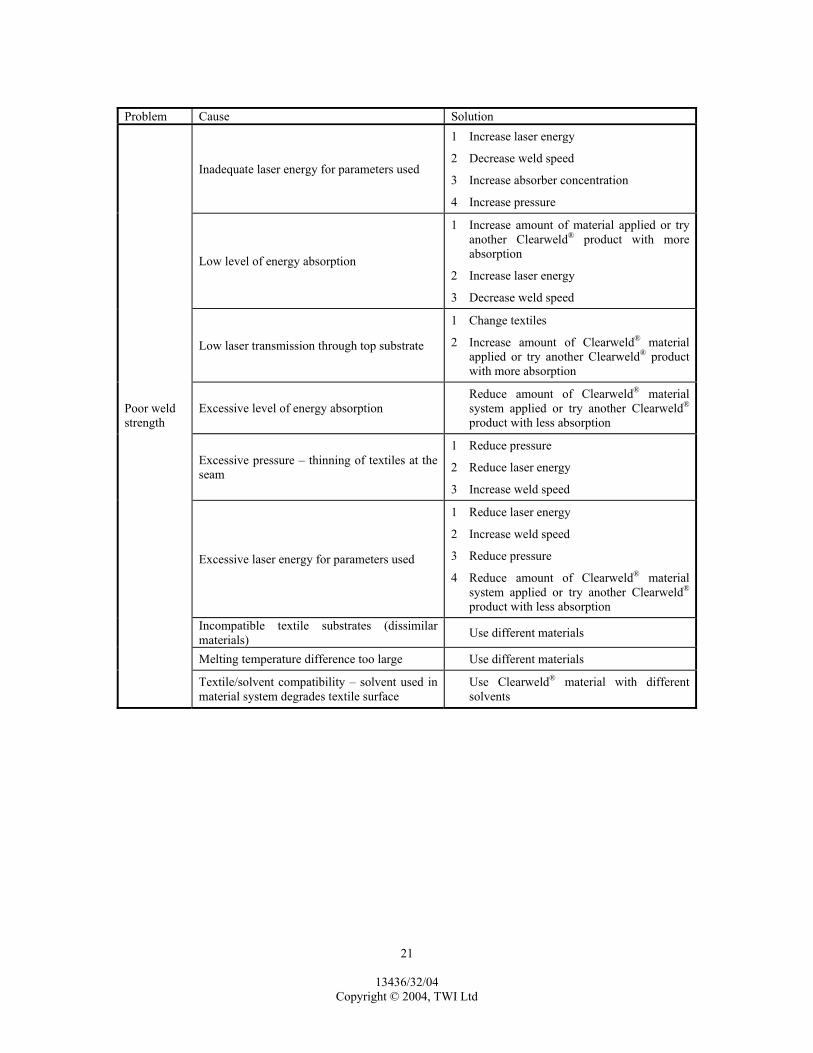
8. TROUBLESHOOTING
8.1. WELDING
Problem Cause Solution
Residual Colour
Excessive level of absorber for laser energy used
1 Reduce amount of Clearweld® material system applied or try another Clearweld® product with less absorption
2 Increase laser energy
Surface contamination, surface roughness, or contamination within the textile
Clean surfaces at the seam and the surface through which the laser beam enters the textile. Remove detrimental additives
Burning Laser-induced breakdown – the result of reaching a threshold energy density at which the material changes from being highly transmissive to highly absorptive
1 Reduce laser energy 2 Eliminate air at the seam or the surface the
beam enters: – applying film tape or other transmissive
plastic (PMMA) over surface – blow inert gas across surface or weld
interface Surface contamination Clean the surface
Surface melting
Laser absorption or scattering at the surface – more likely to occur with semi-crystalline materials. At sufficient energy density, the laser beam scatters or is absorbed at the surface to cause melting
Reduce laser energy
Overheating
1 Reduce laser energy 2 Reduce amount of Clearweld® material
system applied or try another Clearweld® product with less absorption
Inadequate clamping pressure 1 Increase clamping pressure 2 Ensure even pressure (evident if bubbling
always occurs in the same location)
Bubbling in the seam
Entrapped Moisture Ensure textiles are dry prior to welding Uneven clamping pressure Ensure even clamping pressure Uneven absorber layer Examine application of material system
Uneven transmission – patterns or regions with a different textile weight will transmit different amounts of laser energy
1 Change textiles
2 Modify laser energy in problematic area 3 Apply more Clearweld® material in
problematic area
Uneven weld
Inadequate pressure 1 Increase pressure
2 Increase laser energy
13436/32/04 Copyright © 2004, TWI Ltd
21
Problem Cause Solution
Inadequate laser energy for parameters used
1 Increase laser energy
2 Decrease weld speed
3 Increase absorber concentration
4 Increase pressure
Low level of energy absorption
1 Increase amount of material applied or try another Clearweld® product with more absorption
2 Increase laser energy
3 Decrease weld speed
Low laser transmission through top substrate
1 Change textiles
2 Increase amount of Clearweld® material applied or try another Clearweld® product with more absorption
Excessive level of energy absorption Reduce amount of Clearweld® material
system applied or try another Clearweld® product with less absorption
Excessive pressure – thinning of textiles at the seam
1 Reduce pressure
2 Reduce laser energy
3 Increase weld speed
Excessive laser energy for parameters used
1 Reduce laser energy
2 Increase weld speed
3 Reduce pressure
4 Reduce amount of Clearweld® material system applied or try another Clearweld® product with less absorption
Incompatible textile substrates (dissimilar materials) Use different materials
Melting temperature difference too large Use different materials
Poor weld strength
Textile/solvent compatibility – solvent used in material system degrades textile surface
Use Clearweld® material with different solvents
13436/32/04 Copyright © 2004, TWI Ltd
22
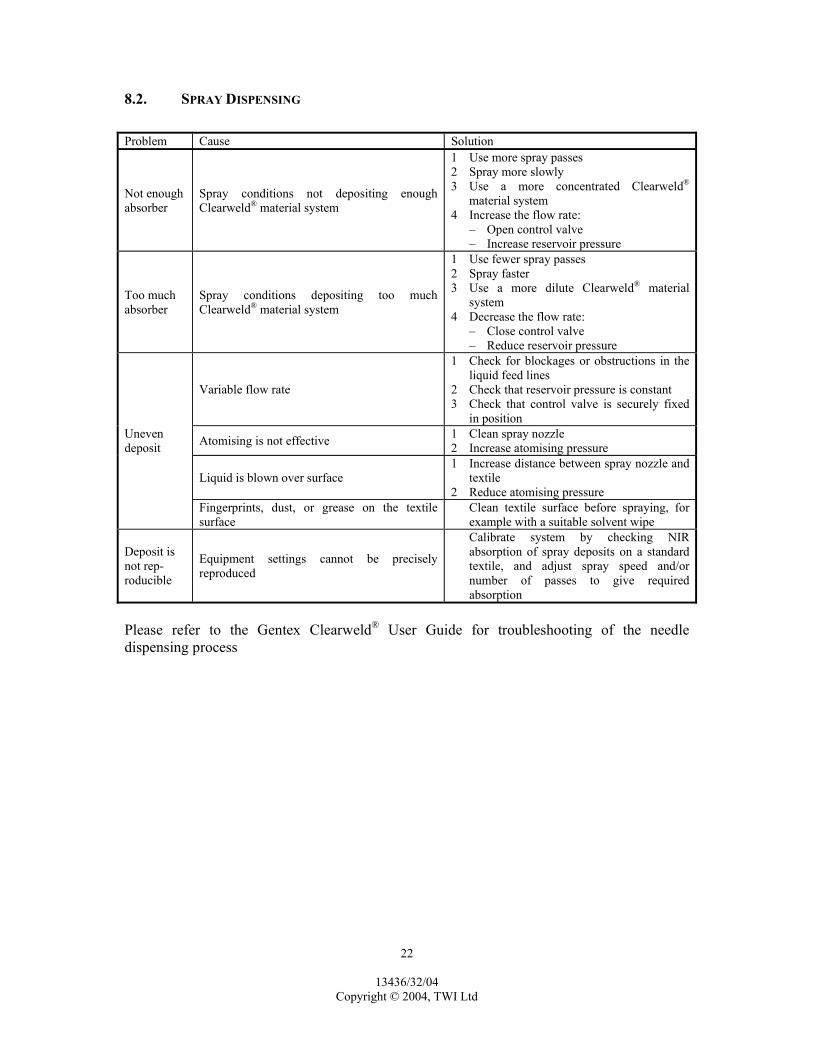
8.2. SPRAY DISPENSING
Problem Cause Solution
Not enough absorber
Spray conditions not depositing enough Clearweld® material system
1 Use more spray passes 2 Spray more slowly 3 Use a more concentrated Clearweld®
material system 4 Increase the flow rate:
– Open control valve – Increase reservoir pressure
Too much absorber
Spray conditions depositing too much Clearweld® material system
1 Use fewer spray passes 2 Spray faster 3 Use a more dilute Clearweld® material
system 4 Decrease the flow rate:
– Close control valve – Reduce reservoir pressure
Variable flow rate
1 Check for blockages or obstructions in the liquid feed lines
2 Check that reservoir pressure is constant 3 Check that control valve is securely fixed
in position
Atomising is not effective 1 Clean spray nozzle 2 Increase atomising pressure
Liquid is blown over surface 1 Increase distance between spray nozzle and
textile 2 Reduce atomising pressure
Uneven deposit
Fingerprints, dust, or grease on the textile surface
Clean textile surface before spraying, for example with a suitable solvent wipe
Deposit is not rep-roducible
Equipment settings cannot be precisely reproduced
Calibrate system by checking NIR absorption of spray deposits on a standard textile, and adjust spray speed and/or number of passes to give required absorption
Please refer to the Gentex Clearweld® User Guide for troubleshooting of the needle dispensing process

13436/32/04 Copyright © 2004, TWI Ltd
23
9. DEFINITIONS
NIR Absorber – a substance that is able to absorb laser energy, thereby causing a physical and/or chemical reaction to generate heat as the absorbed energy is dissipated. It is a component of Clearweld® material systems. Clearweld® Material System – Solvent based, low viscosity material used to perform the Clearweld® laser welding process. Beer-Lambert Law – shows a linear relationship between absorbance and concentration of an absorbing species: A = λlpC where A is absorbance, λ is the wavelength dependent
absorptivity coefficient, l is the path length through the sample and c is the concentration.
Carbon Black – essentially elemental carbon in the form of fine particulates. Carbon black absorbs at all wavelengths in the electromagnetic spectrum. Cytotoxicity –tests which uses cell culture assays to test the biocompatibility of a material or extract through the use of isolated cells in vitro. Evaluates the toxicity or irritancy potential of a material or chemical. Diode Laser – also known as a semiconductor laser. A light emitting diode designed to use stimulated emission to form coherent light. Extinction Coefficient – The proportionality constant in the Beer-Lambert Equation which measures the effectiveness of absorption of light of a given wavelength by a given absorbing species: ε = A/(c*t) where ε is the extinction coefficient, A is the
absorbance, c is the concentration, and t the thickness all referenced to a given wavelength.
Heat Affected Zone (HAZ) – the region of material near the weld melt pool where the heat altered the polymeric structure. The boundaries of the heat affected zone are difficult to define since the melting temperature or glass transition temperature does not occur at a single temperature, but rather over a range of temperatures. Nd:YAG Laser – a solid state laser that utilises a yttrium-aluminium-garnet rod doped with neodymium as the lasing medium. Laser light is produced at 1064nm. Near Infrared (NIR) Light – region of the electromagnetic spectrum between 780nm-1500nm. Thermoplastic – a polymer that softens upon heating and hardens upon cooling. The processes are reversible and repeatable.

13436/32/04 Copyright © 2004, TWI Ltd
24
Thermoset – a polymer that is cured or hardened by heat and will not soften or melt when reheated but will begin to decompose when heated to a high enough temperature. Through Transmission Laser Welding – a plastics welding process in which a laser is the source of energy. The laser transmits through one substrate and is absorbed at the interface that is to be welded. The absorbing material may be carbon black, other inorganic materials such as titanium dioxide, or organic materials. 10. ACKNOWLEDGEMENTS
The assistance of the LASPET project partners in the preparation of this document is gratefully acknowledged: • Blackman & White. • Dispensing Automation. • Gentex Corporation. • Invista. • Lindstrand Balloons. • Marks & Spencer. • North Sails. • Porvair. • TWI. • Rofin. We are particularly grateful to Gentex for their detailed review of these Guidelines. The project through which these guidelines were developed was part funded by the UK Department of Trade and Industry.

13436/32/04 Copyright © 2004, TWI Ltd
TWI ENDORSEMENT The report has been reviewed in accordance with TWI policy. Project Leader ………………………………. TGM/Reviewer ………………………….. (Signature) (Signature) Print name …………………………………… Print name ……………………………….. Secretary/Administrator …………………………………… (Signature) Print name ………………………………………………….