clinical information using uml (unified modeling language) · • uml (unified modeling language)...
TRANSCRIPT
10/10/2016
1
Modeling Clinical Information Using UML (Unified Modeling Language)
Sakda Arj‐ong Vallipakorn, MD, Ph.D.MSIT, MAIS.(Information Science)
Section For Clinical Epidemiology and Biostatistics, Faculty of Medicine
Ramathibodi Hospital, Mahidol University
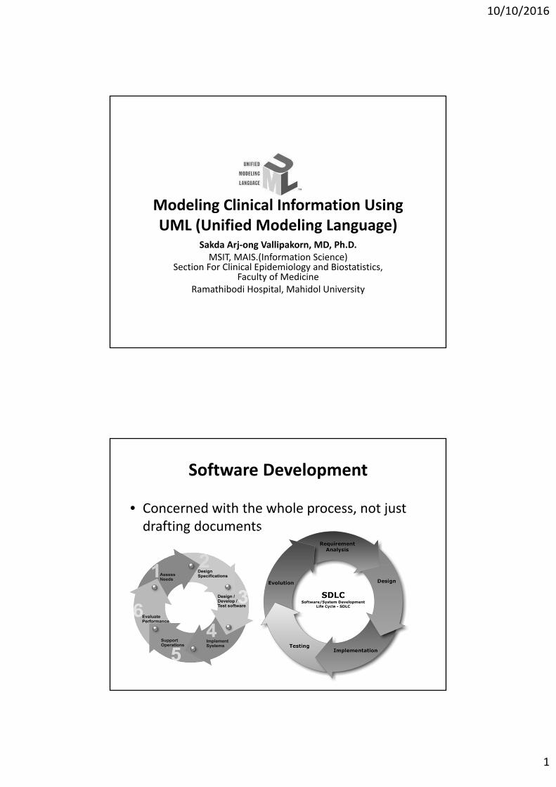
Software Development
• Concerned with the whole process, not just drafting documents
10/10/2016
2
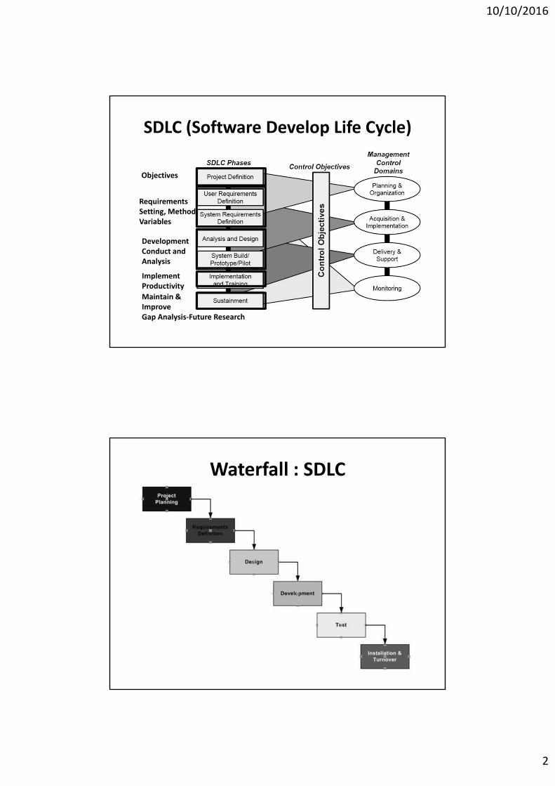
SDLC (Software Develop Life Cycle)
Objectives
RequirementsSetting, MethodVariables
DevelopmentConduct andAnalysis
ImplementProductivity
Maintain & ImproveGap Analysis‐Future Research
Waterfall : SDLC
10/10/2016
3
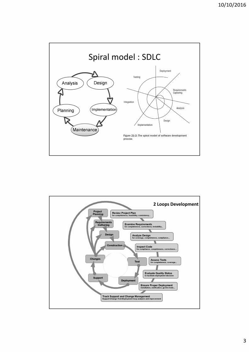
Spiral model : SDLC
2 Loops Development
10/10/2016
4
M
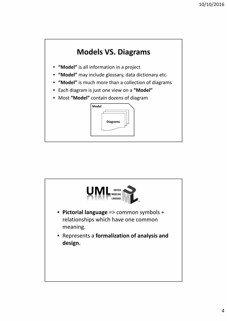
Models VS. Diagrams
• “Model” is all information in a project
• “Model” may include glossary, data dictionary etc.
• “Model” is much more than a collection of diagrams
• Each diagram is just one view on a “Model”
• Most “Model” contain dozens of diagram
Diagrams
Model
• Pictorial language => common symbols + relationships which have one common meaning.
• Represents a formalization of analysis and design.
10/10/2016
5
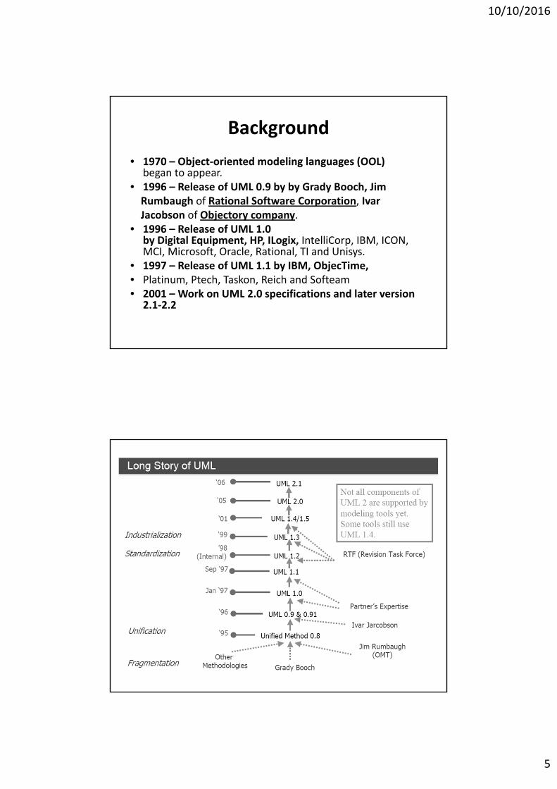
Background
• 1970 – Object‐oriented modeling languages (OOL) began to appear.
• 1996 – Release of UML 0.9 by by Grady Booch, JimRumbaugh of Rational Software Corporation, IvarJacobson of Objectory company.
• 1996 – Release of UML 1.0 by Digital Equipment, HP, ILogix, IntelliCorp, IBM, ICON, MCI, Microsoft, Oracle, Rational, TI and Unisys.
• 1997 – Release of UML 1.1 by IBM, ObjecTime,• Platinum, Ptech, Taskon, Reich and Softeam• 2001 – Work on UML 2.0 specifications and later version
2.1‐2.2
10/10/2016
6
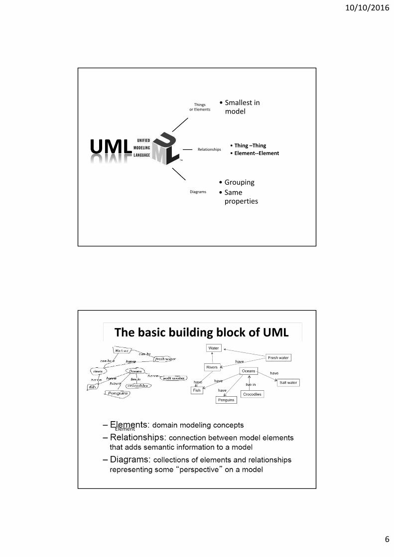
Thingsor Elements
• Smallest in model
Relationships• Thing –Thing
• Element‐‐Element
Diagrams
• Grouping
• Same properties
The basic building block of UML
Element
10/10/2016
7
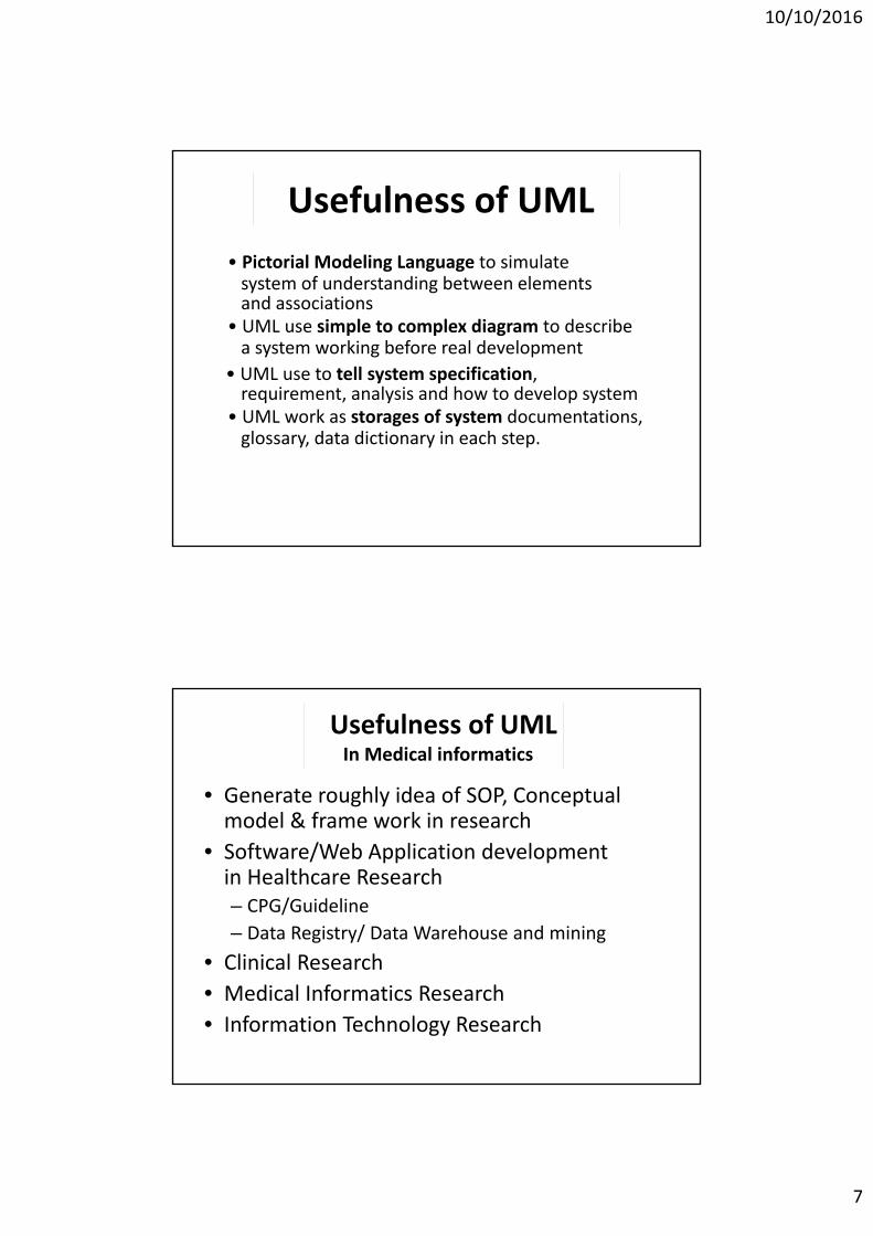
• Pictorial Modeling Language to simulate system of understanding between elements and associations
• UML use simple to complex diagram to describe a system working before real development
• UML use to tell system specification, requirement, analysis and how to develop system
• UML work as storages of system documentations, glossary, data dictionary in each step.
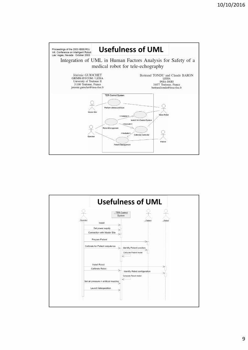
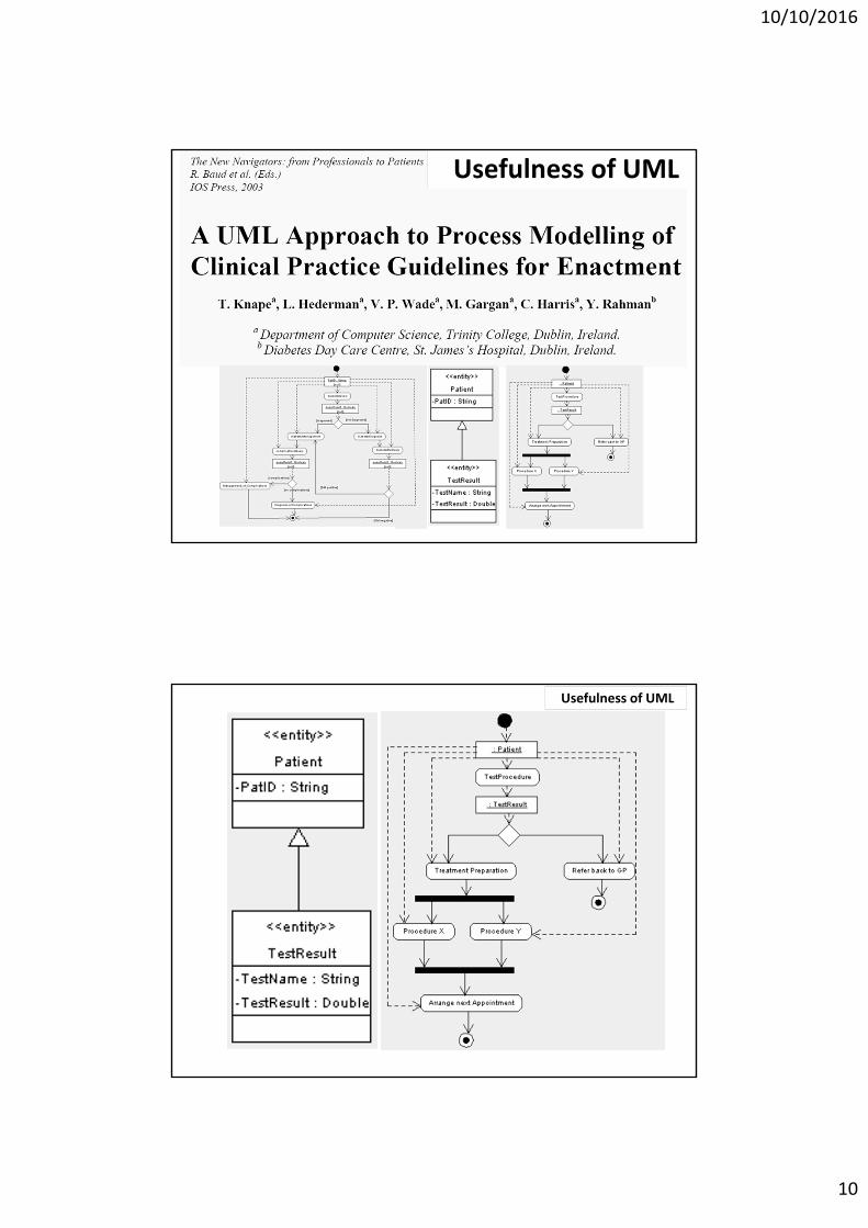
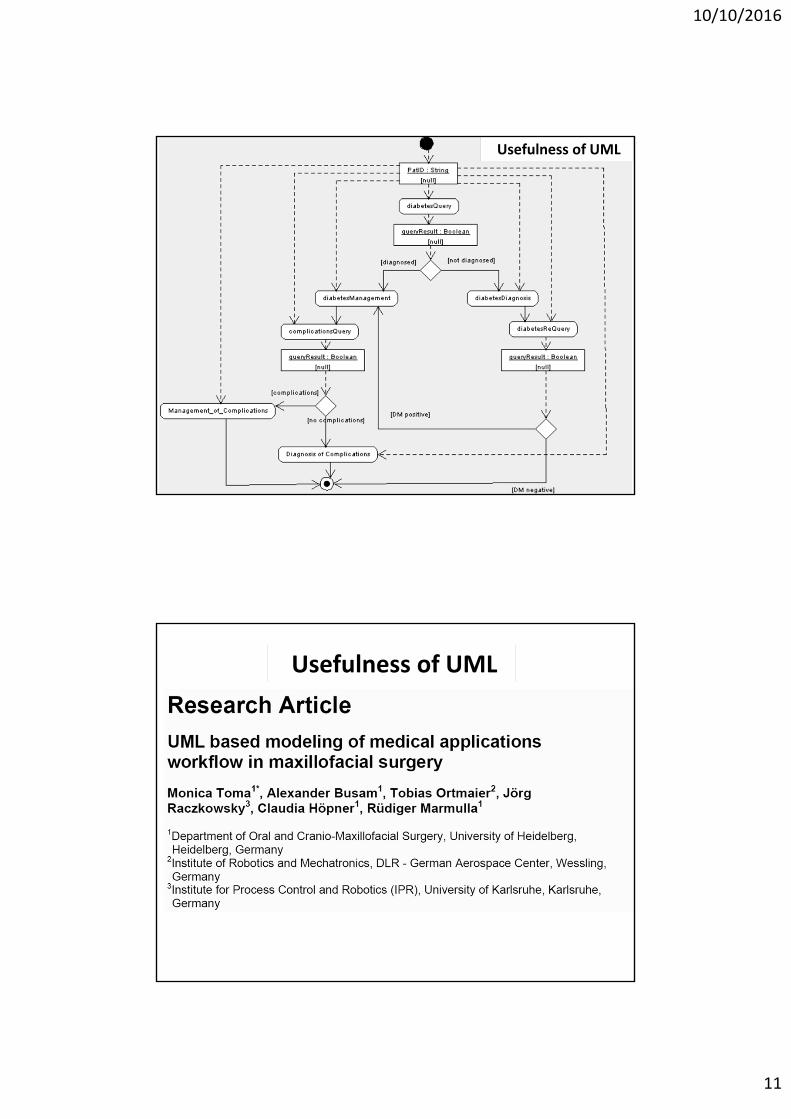
Usefulness of UML
• Generate roughly idea of SOP, Conceptual model & frame work in research
• Software/Web Application development in Healthcare Research– CPG/Guideline
– Data Registry/ Data Warehouse and mining
• Clinical Research
• Medical Informatics Research
• Information Technology Research
Usefulness of UMLIn Medical informatics
10/10/2016
8
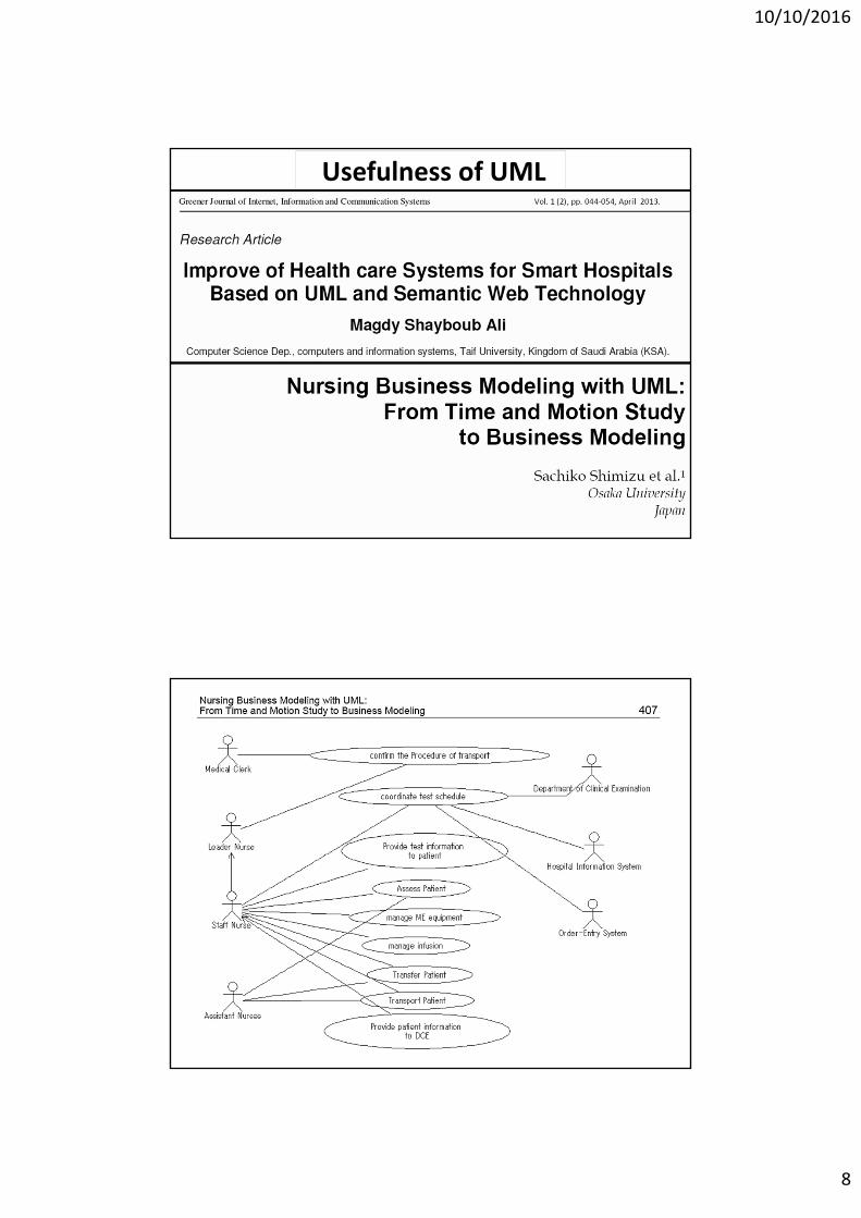
Usefulness of UML
10/10/2016
9
Usefulness of UML
Usefulness of UML
10/10/2016
10
Usefulness of UML
Usefulness of UML
10/10/2016
11
Usefulness of UML
Usefulness of UML
10/10/2016
12
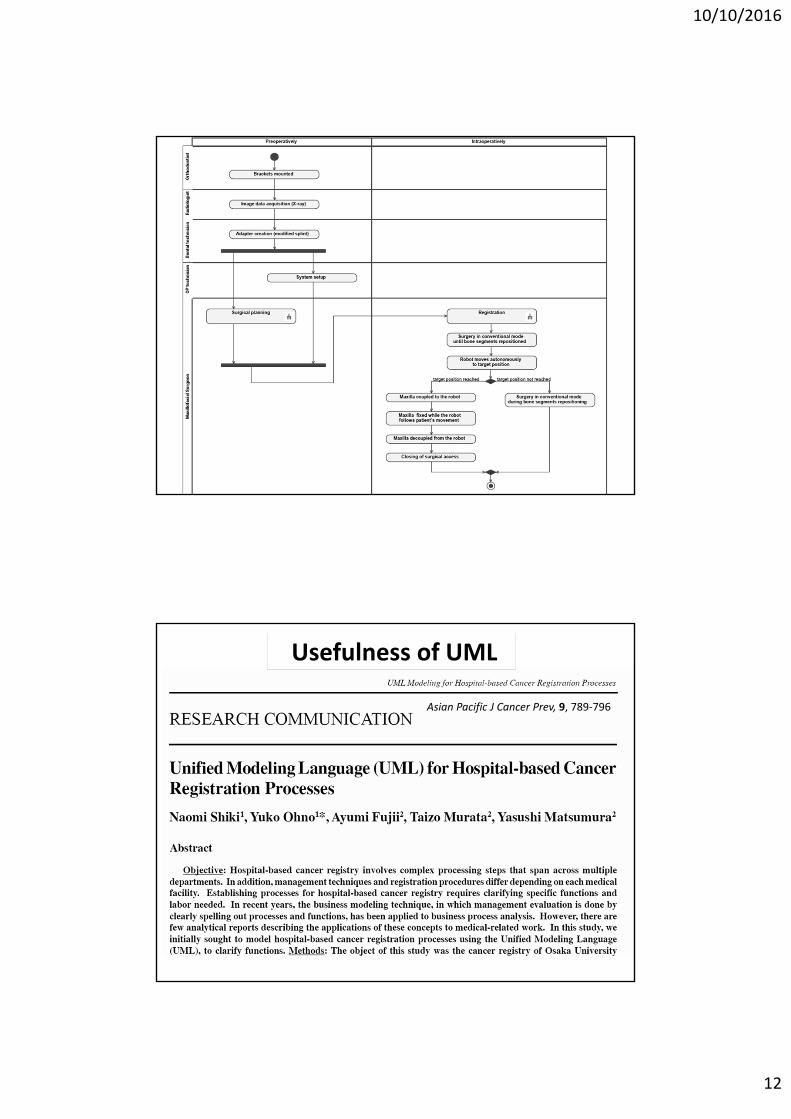
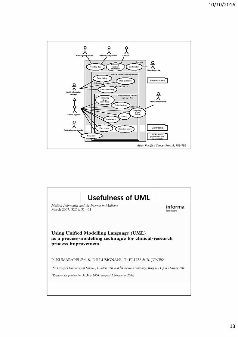
Usefulness of UML
Asian Pacific J Cancer Prev, 9, 789‐796
10/10/2016
13
Asian Pacific J Cancer Prev, 9, 789‐796
Usefulness of UML
10/10/2016
14
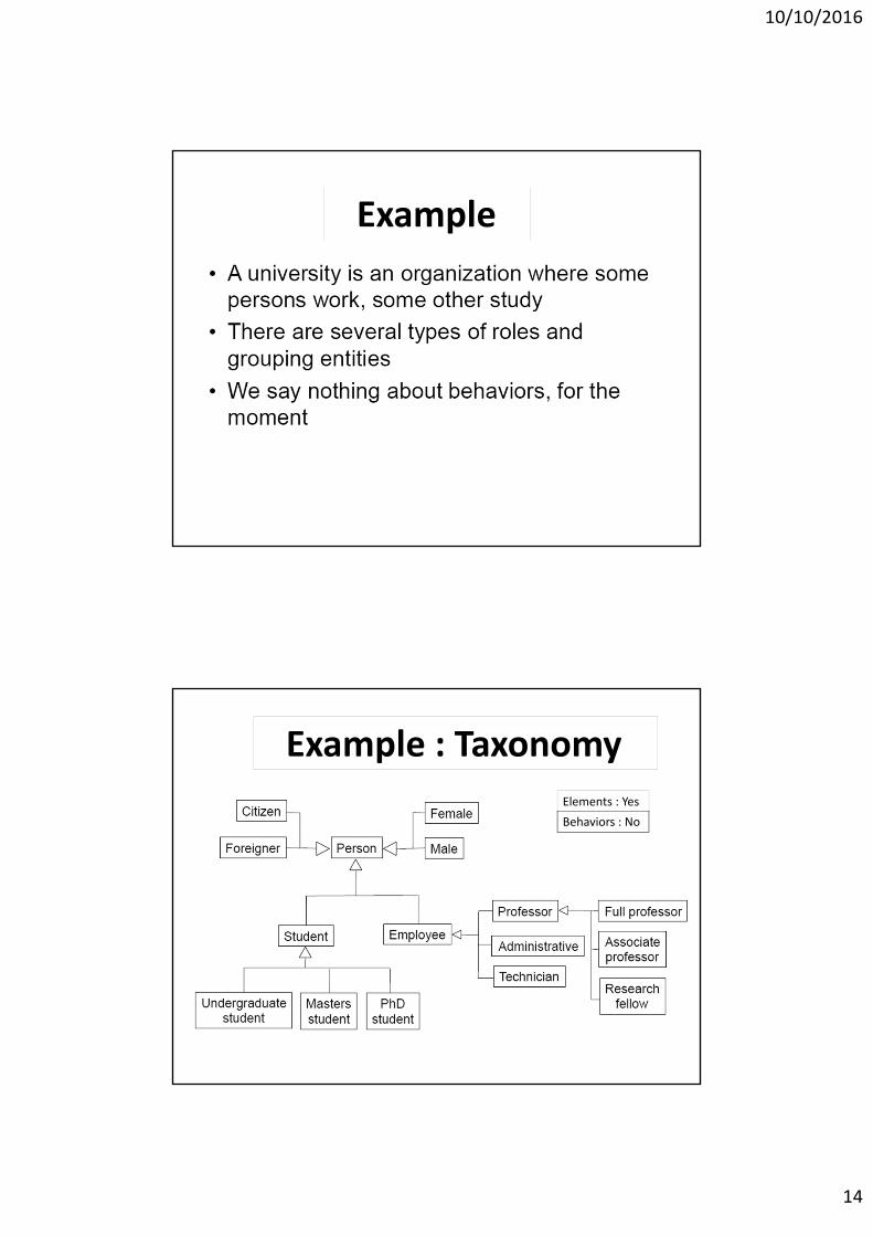
Example
Elements : Yes
Behaviors : No
Example : Taxonomy

10/10/2016
15
UML
Elements(Things) Relationships Diagrams
10/10/2016
16
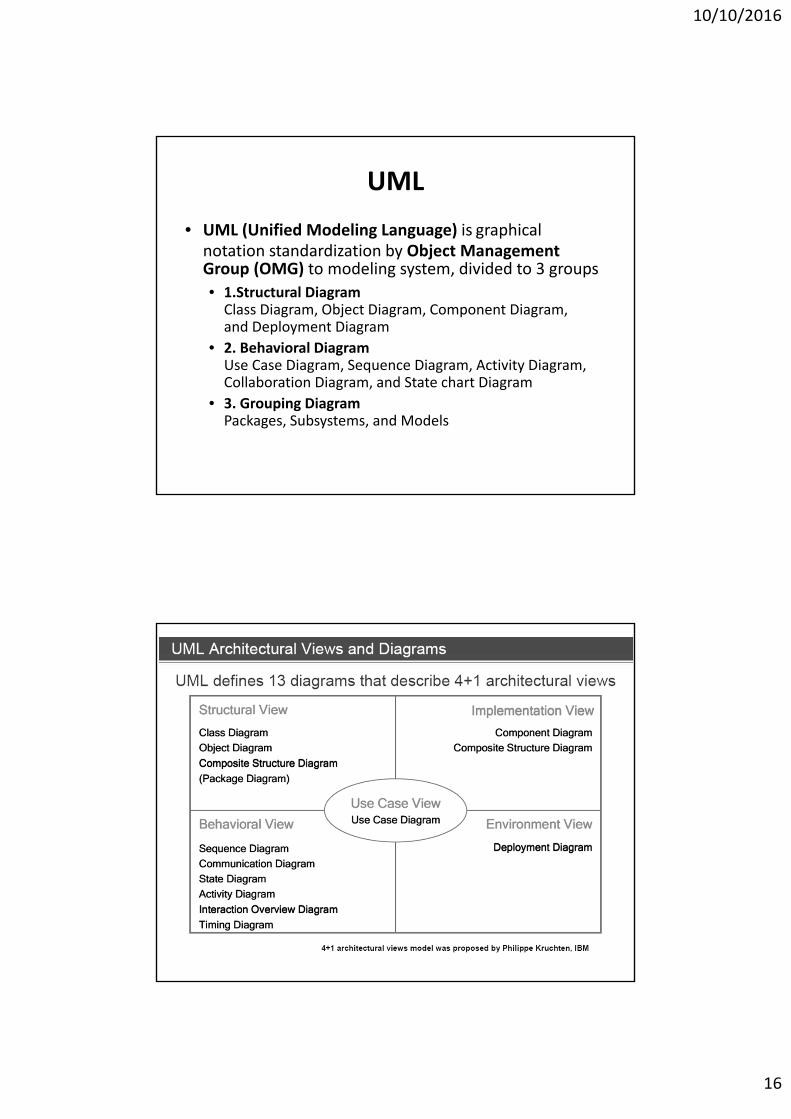
UML
• UML (Unified Modeling Language) is graphical notation standardization by Object Management Group (OMG) to modeling system, divided to 3 groups
• 1.Structural DiagramClass Diagram, Object Diagram, Component Diagram, and Deployment Diagram
• 2. Behavioral DiagramUse Case Diagram, Sequence Diagram, Activity Diagram, Collaboration Diagram, and State chart Diagram
• 3. Grouping Diagram Packages, Subsystems, and Models
10/10/2016
17
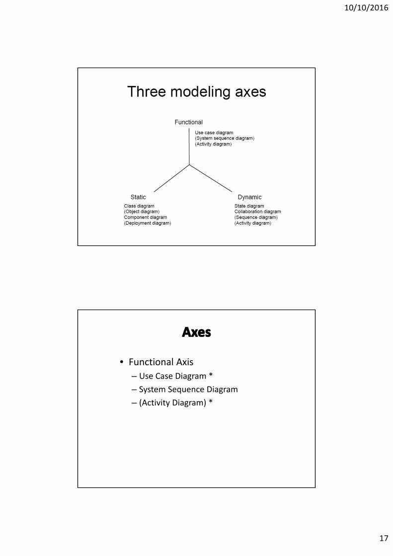
3 model axes
• Functional Axis
– Use Case Diagram *
– System Sequence Diagram
– (Activity Diagram) *
10/10/2016
18
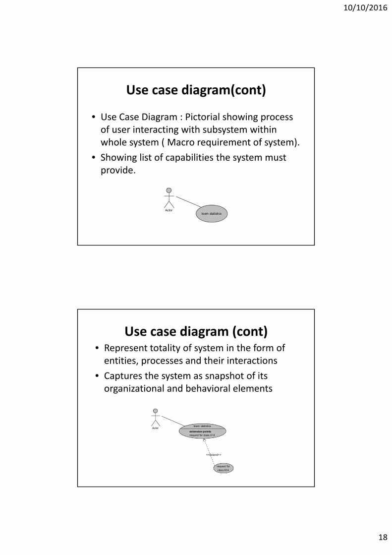
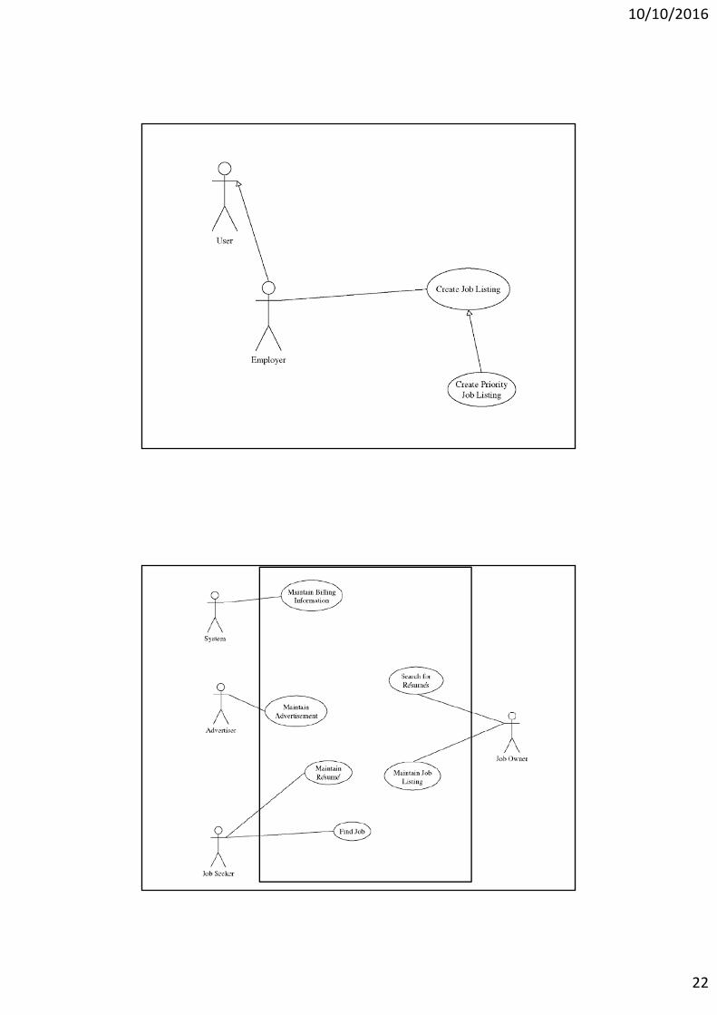
Use case diagram(cont)
• Use Case Diagram : Pictorial showing process of user interacting with subsystem within whole system ( Macro requirement of system).
• Showing list of capabilities the system must provide.
Use case diagram (cont)• Represent totality of system in the form of entities, processes and their interactions
• Captures the system as snapshot of its organizational and behavioral elements
10/10/2016
19
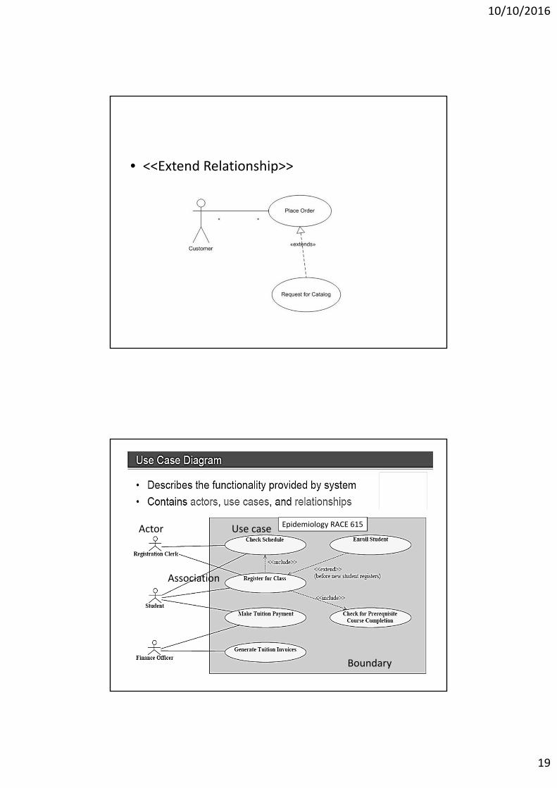
• <<Extend Relationship>>
Actor Use case
Association
Boundary
Epidemiology RACE 615
10/10/2016
20
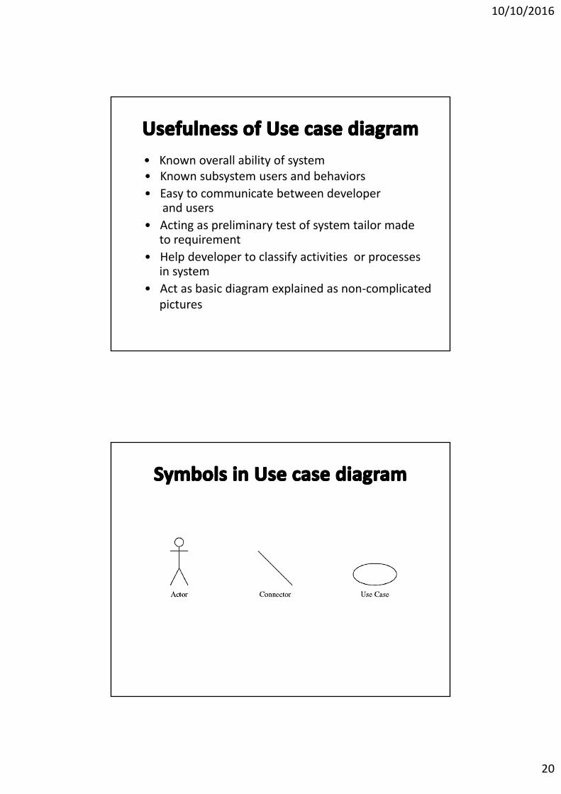
• Known overall ability of system• Known subsystem users and behaviors
• Easy to communicate between developer and users
• Acting as preliminary test of system tailor made to requirement
• Help developer to classify activities or processes in system
• Act as basic diagram explained as non‐complicated pictures
10/10/2016
21
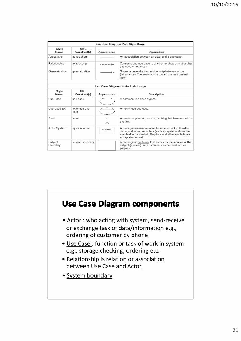
• Actor : who acting with system, send‐receive or exchange task of data/information e.g., ordering of customer by phone
• Use Case : function or task of work in system e.g., storage checking, ordering etc.
• Relationship is relation or association between Use Case and Actor
• System boundary
10/10/2016
22
10/10/2016
23
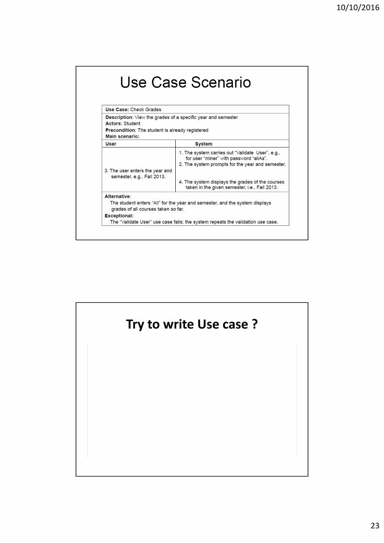
Try to write Use case ?
10/10/2016
24
Try to write Use case of ATM withdrawal
Try to write Use case of OPD Services
10/10/2016
25
Try to write Use case of DM Clinic
• Static Axis
– Class Diagram (Object Diagram)*
– Component Diagram (Deployment Diagram)
10/10/2016
26
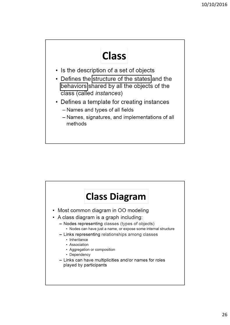
• Is the description of a set of objects
• Defines the structure of the states and the
behaviors shared by all the objects of the
class (called instances)
• Defines a template for creating instances
– Names and types of all fields
– Names, signatures, and implementations of all
methods
Class
2.Class diagram(cont)Class Diagram
10/10/2016
27
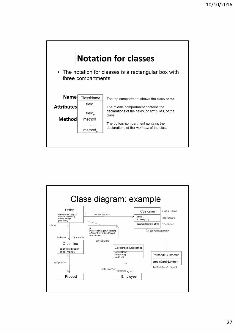
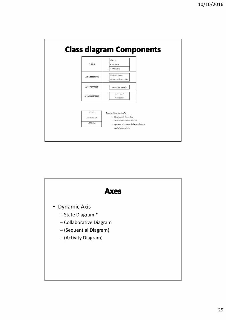
Notation of classNotation for classes
Name
Attributes
Method
Class diagram example
10/10/2016
28
Class diagram
• Class Diagram show a Static Relationship (not Dynamic Relationship)
• Class Diagram show the grouping of each classes and their relations
• Component of Class(Name‐Attribute‐Method) and Relationship of Classes and function will show in Class Diagram
Class (Relationship)
• Dependency Relationship : e.g. “Class Customer” and “Class Order” “Class Order” depend on “Class Customer” because when customer change the request of order, or increase amount of production the ordering will be update directly base on customer
• Inheritance Relationships:e.g. Super class will inherit property of class through Sub class (mother daughter)
• Association Relationships:“Class student” association with “Class RACE615” in aspect of study registration
10/10/2016
29
• Dynamic Axis
– State Diagram *
– Collaborative Diagram
– (Sequential Diagram)
– (Activity Diagram)
10/10/2016
30
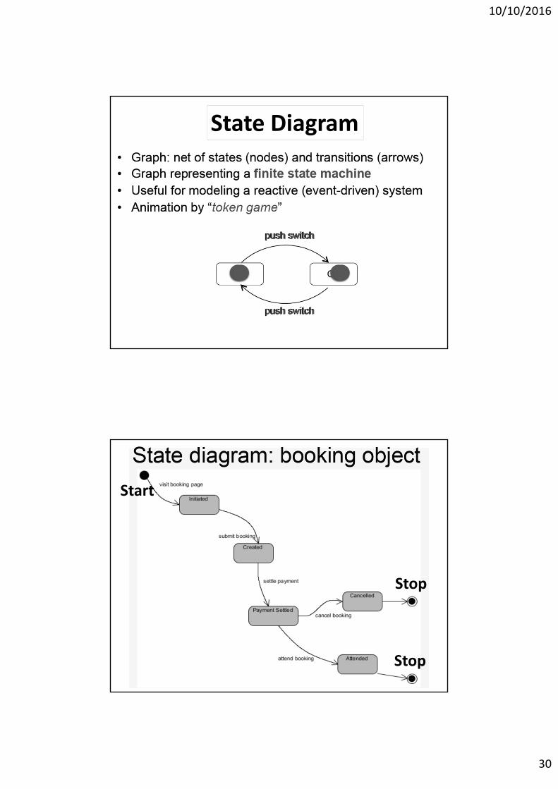
State DiagramState Diagram
Start
Stop
Stop
10/10/2016
31
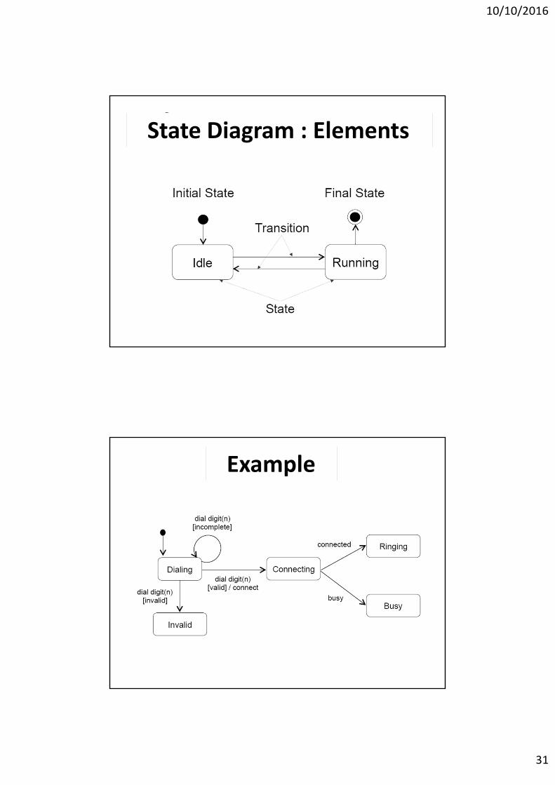
State Diagram : Elements
Example
10/10/2016
32
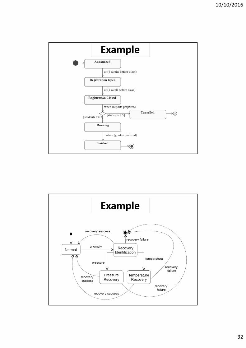
Example
Example
10/10/2016
33
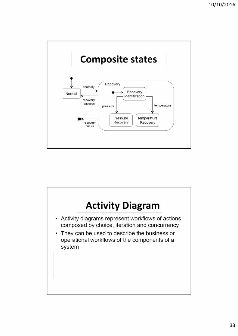
Composite states
Activity Diagram
10/10/2016
34
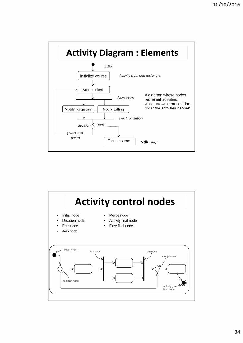
Activity Diagram : Elements
Activity control nodes
10/10/2016
35
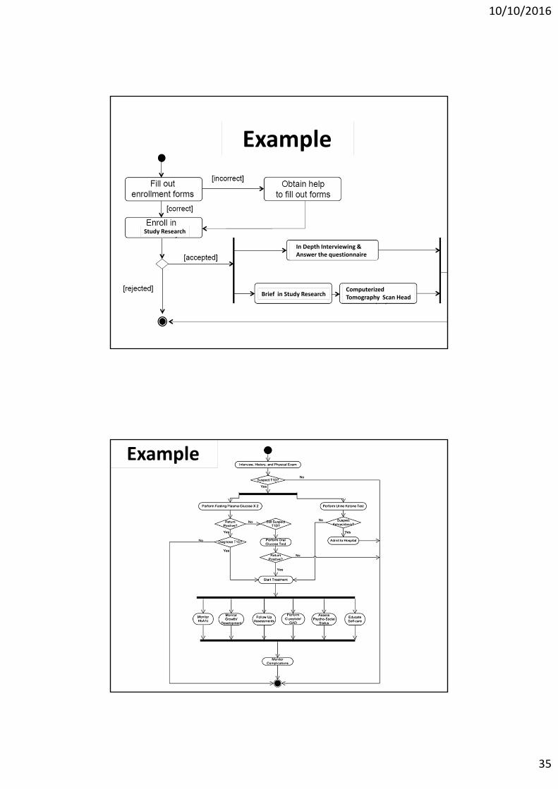
Example
Study Research
Brief in Study Research
In Depth Interviewing &Answer the questionnaire
Computerized Tomography Scan Head
Example
10/10/2016
36
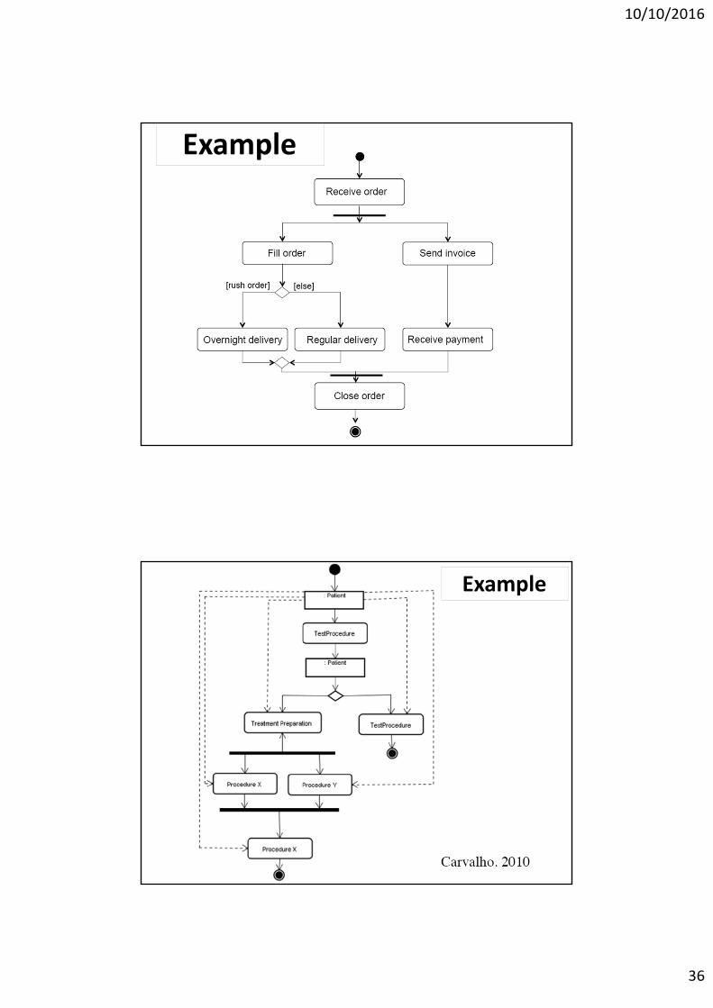
Example
Example
10/10/2016
37
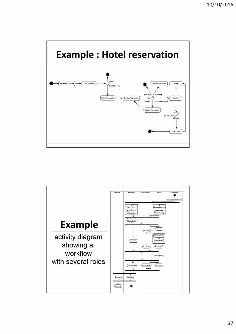
Example : Hotel reservation
Example
10/10/2016
38
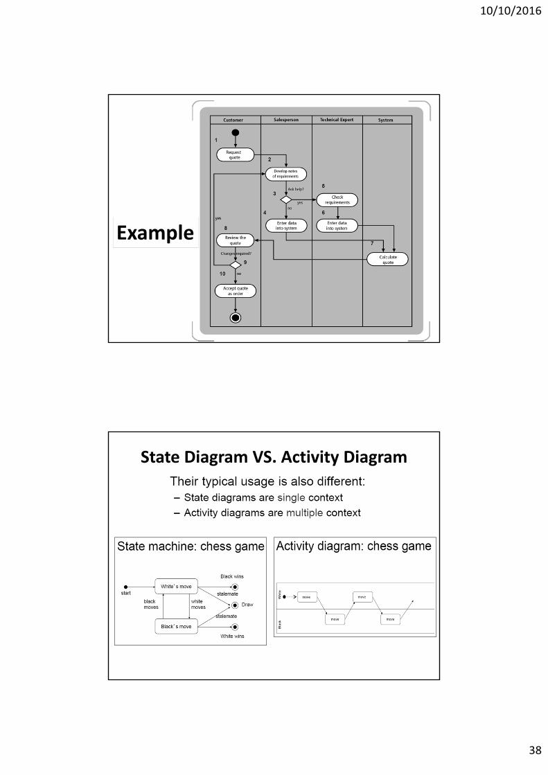
Example
State Diagram VS. Activity Diagram
10/10/2016
39
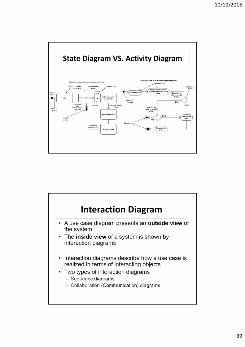
State Diagram VS. Activity Diagram
Interaction Diagram
10/10/2016
40
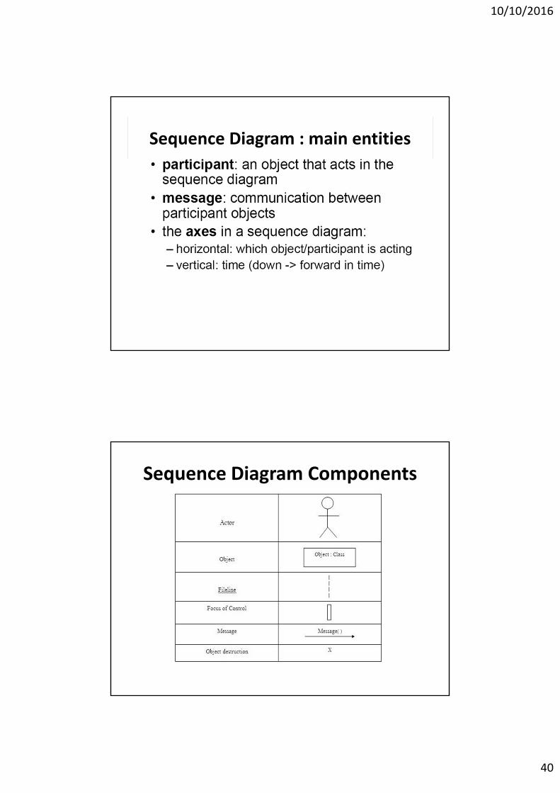
Sequence Diagram : main entities
Sequence Diagram Components
10/10/2016
41
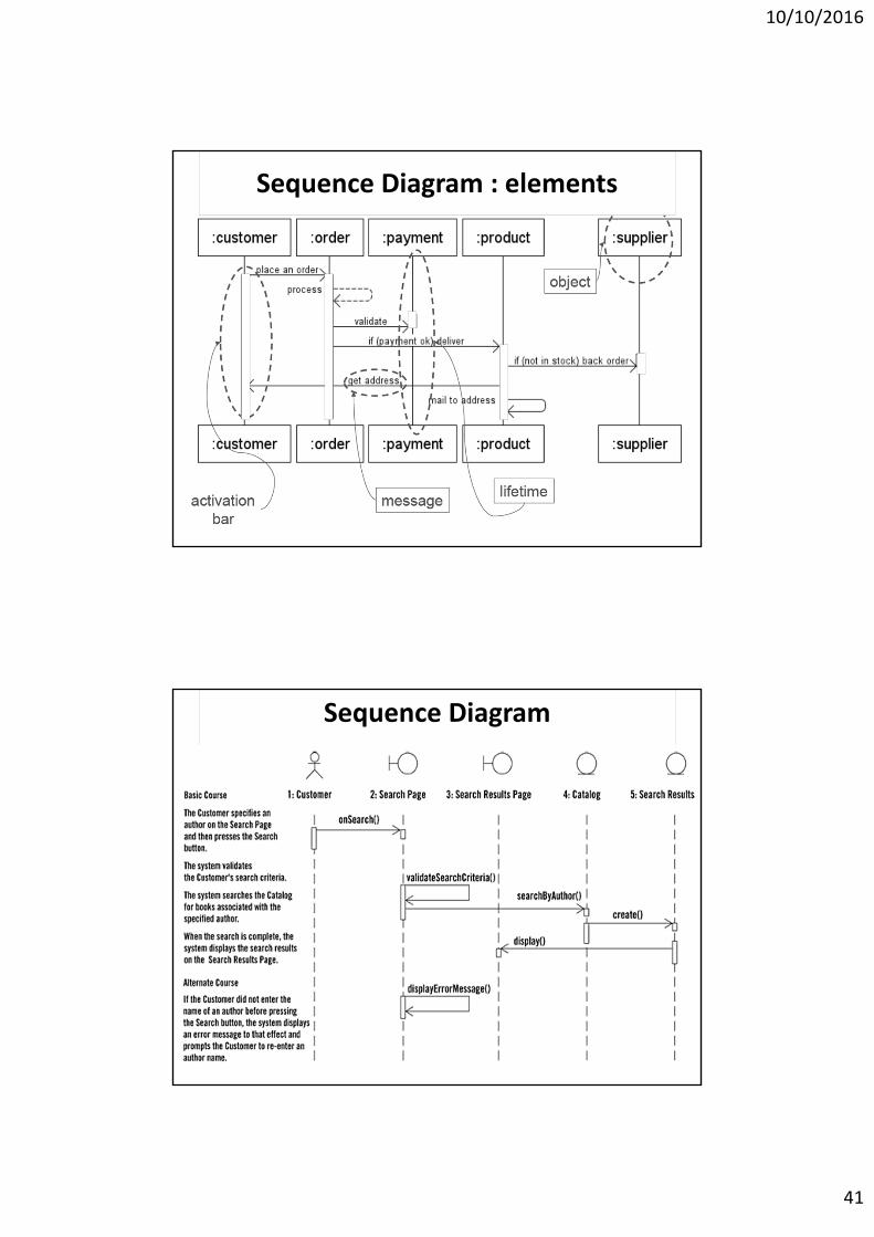
Sequence Diagram : elements
Sequence Diagram
10/10/2016
42
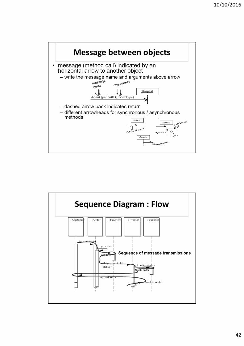
Message between objects
Sequence Diagram : Flow
10/10/2016
43
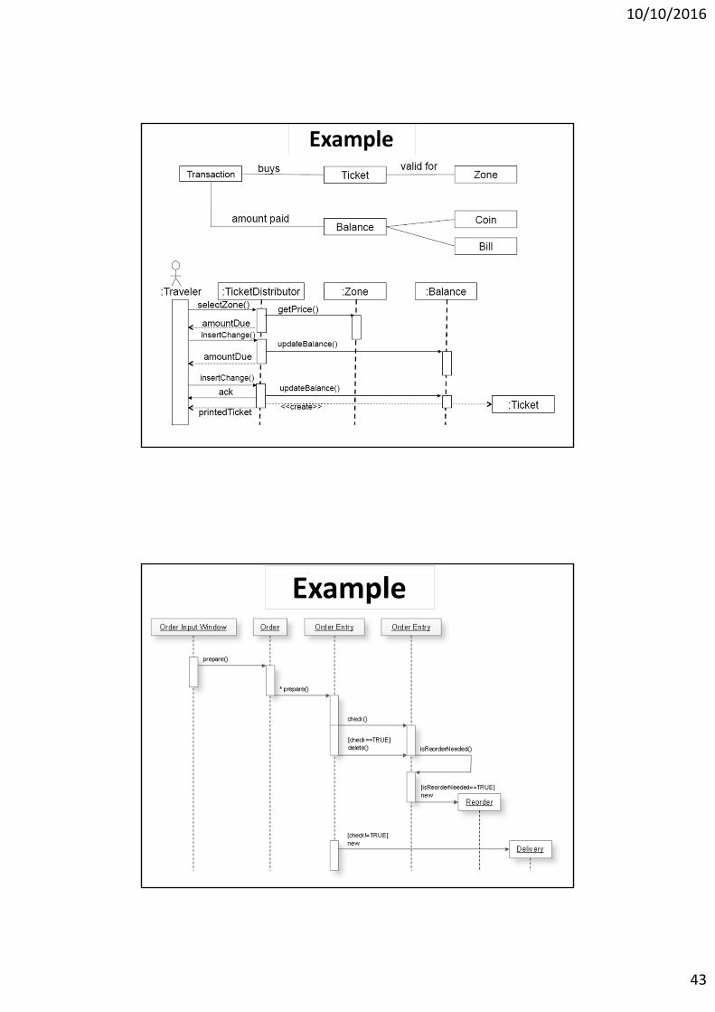
Example
Example
10/10/2016
44
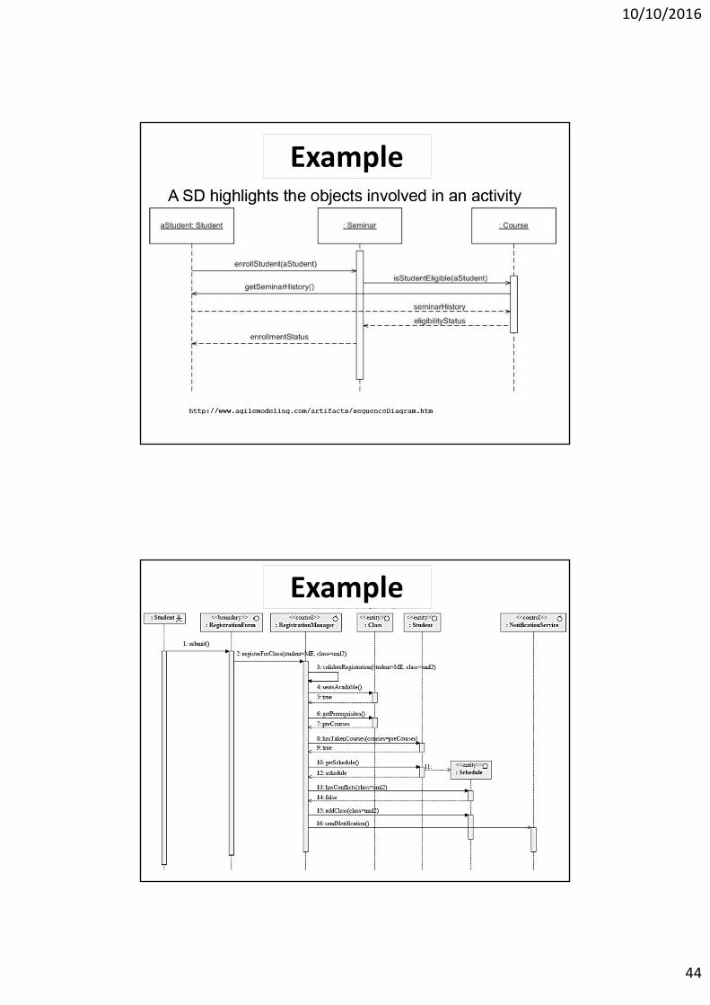
Example
ExampleExample
10/10/2016
45
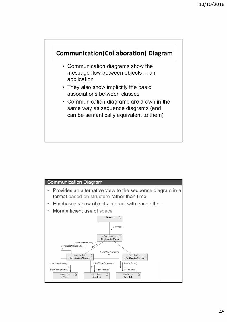
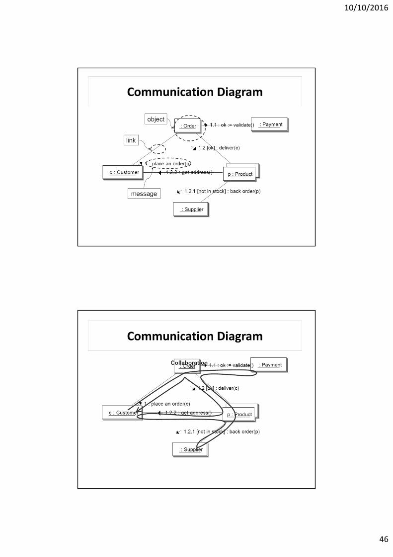
Communication(Collaboration) Diagram
10/10/2016
46
Communication Diagram
Communication Diagram
10/10/2016
47
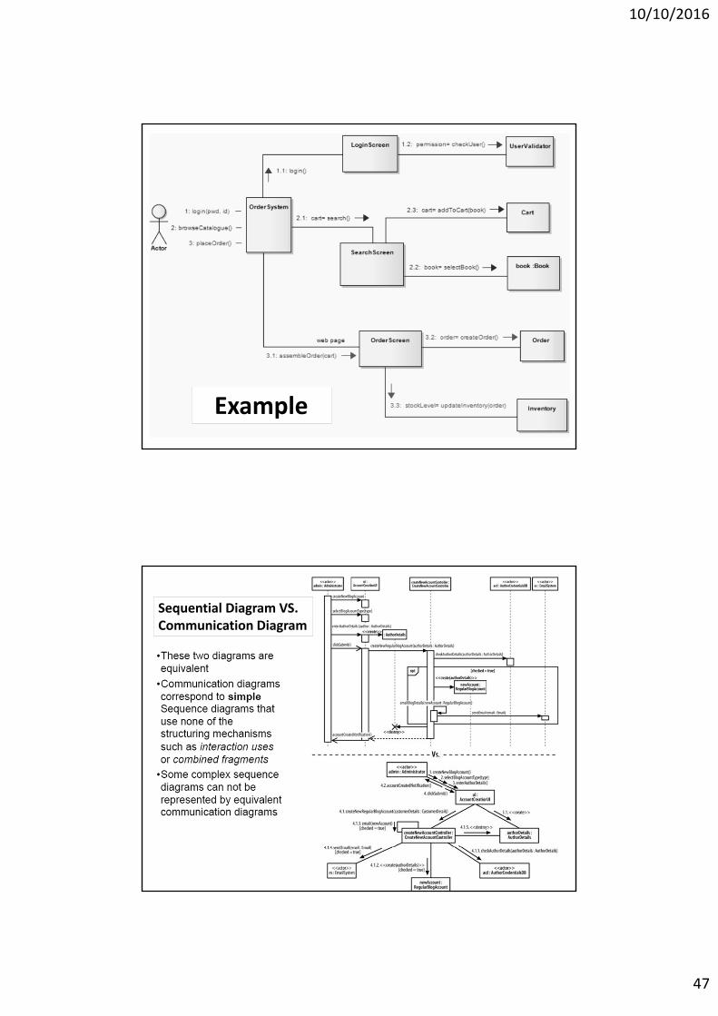
Example
Sequential Diagram VS. Communication Diagram
10/10/2016
48
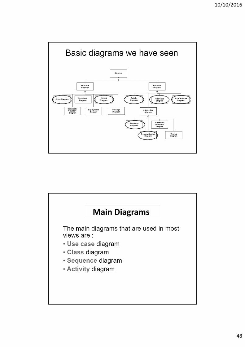
Main Diagrams
10/10/2016
49
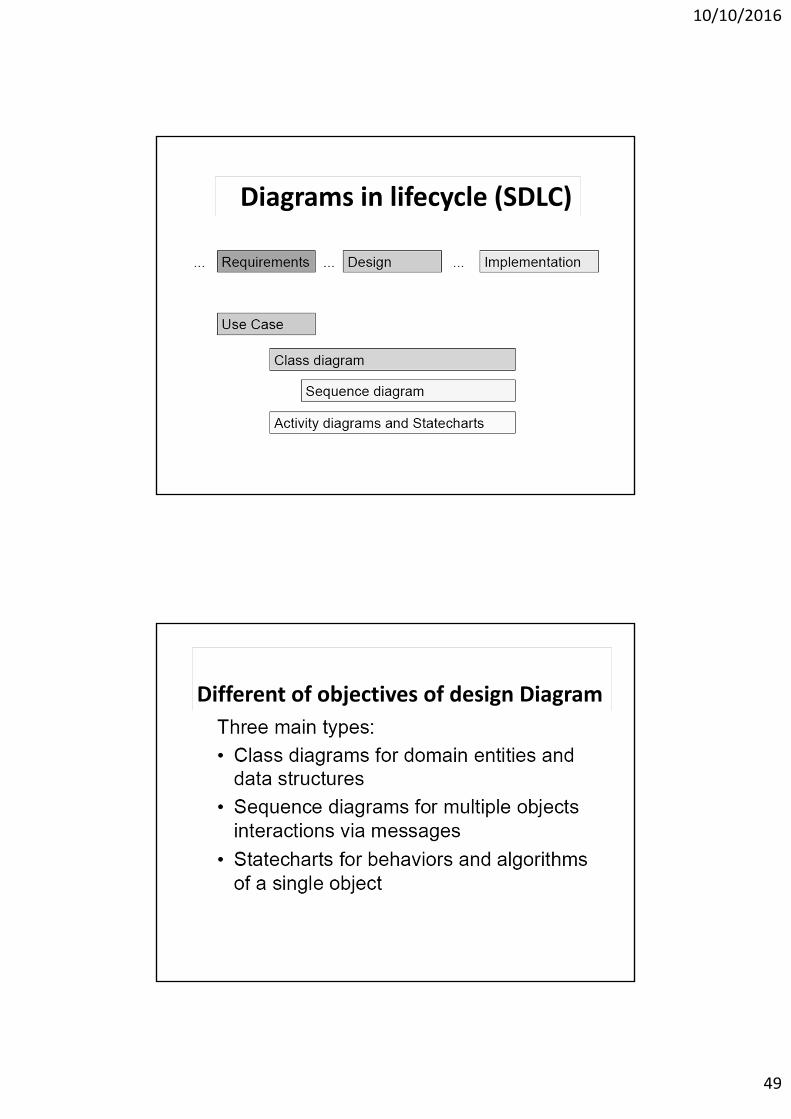
Diagrams in lifecycle (SDLC)
Different of objectives of design Diagram
10/10/2016
50
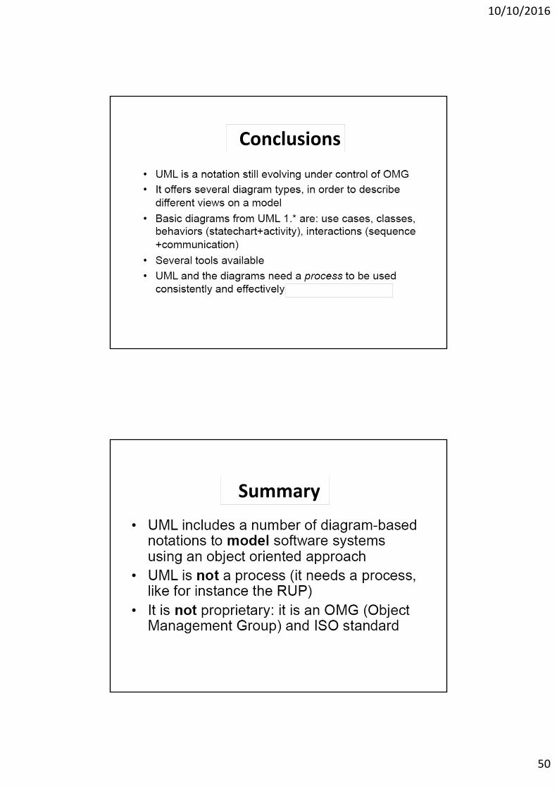
Conclusions
Summary
10/10/2016
51
Thank Youfor
Attention