uml the unified modeling language. brief summary of uml (the unified modeling language) the uml is a...
Post on 21-Dec-2015
255 views
TRANSCRIPT
UMLUML
The Unified Modeling Language
Brief Summary of UML(The Unified Modeling Language)
The UML is a language forThe UML is a language for•visualizingvisualizing•specifyingspecifying•constructingconstructing•DocumentingDocumenting
It is used to understand, design, browse, configure, It is used to understand, design, browse, configure, maintain, and control information about systems.maintain, and control information about systems.
The UML uses mostly graphical notations to express the The UML uses mostly graphical notations to express the OO analysis and design of software projects. OO analysis and design of software projects.
Simplifies the complex process of software designSimplifies the complex process of software design
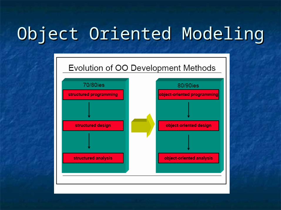
Object Oriented ModelingObject Oriented Modeling
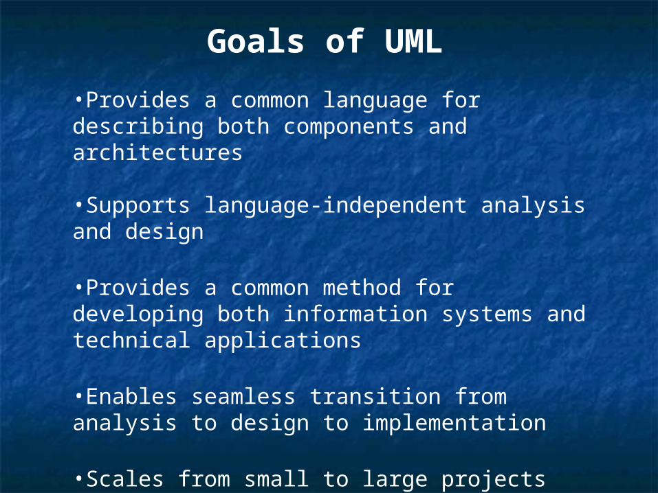
Goals of UML
•Provides a common language for describing both components and architectures
•Supports language-independent analysis and design
•Provides a common method for developing both information systems and technical applications
•Enables seamless transition from analysis to design to implementation
•Scales from small to large projects
•Facilitates iterative development
UML Assessment•UML is messy, imprecise, complex.
•You don’t have to know or use every feature of UML any more than you need to know or use every feature of a large software application or programming language.
•UML can be and has been used in many different ways in real-world development projects.
•UML is more than a visual notation. UML models can be used to generate code and test cases.
Model:
•Models are the language of designer, in many disciplines
•Models are representations of the system to-be-built or as-built
•Models are vehicle for communications with various stakeholders
•Models allow reasoning about some characteristic of the real system
Types of UML DiagramsTypes of UML Diagrams
Use Case DiagramUse Case Diagram
Class DiagramClass Diagram
Sequence DiagramSequence Diagram
Collaboration DiagramCollaboration Diagram
State DiagramState Diagram
Activity DiagramActivity Diagram
Interaction DiagramInteraction Diagram
Deployment DiagramDeployment Diagram
Component Diagram Component Diagram
This is only a subset of diagrams … but are most widely usedThis is only a subset of diagrams … but are most widely used
Use Case DiagramUse Case Diagram
Used for describing a set of user scenarios
Mainly used for capturing user requirements
Work like a contract between end user and software developers
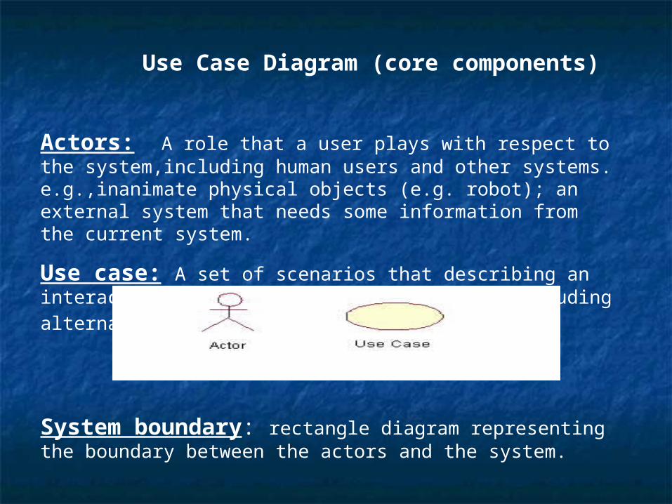
Use Case Diagram (core components)
Actors: A role that a user plays with respect to the system,including human users and other systems. e.g.,inanimate physical objects (e.g. robot); an external system that needs some information from the current system.
Use case: A set of scenarios that describing an interaction between a user
and a system, including alternatives.
System boundary: rectangle diagram representing the boundary between the actors and the system.
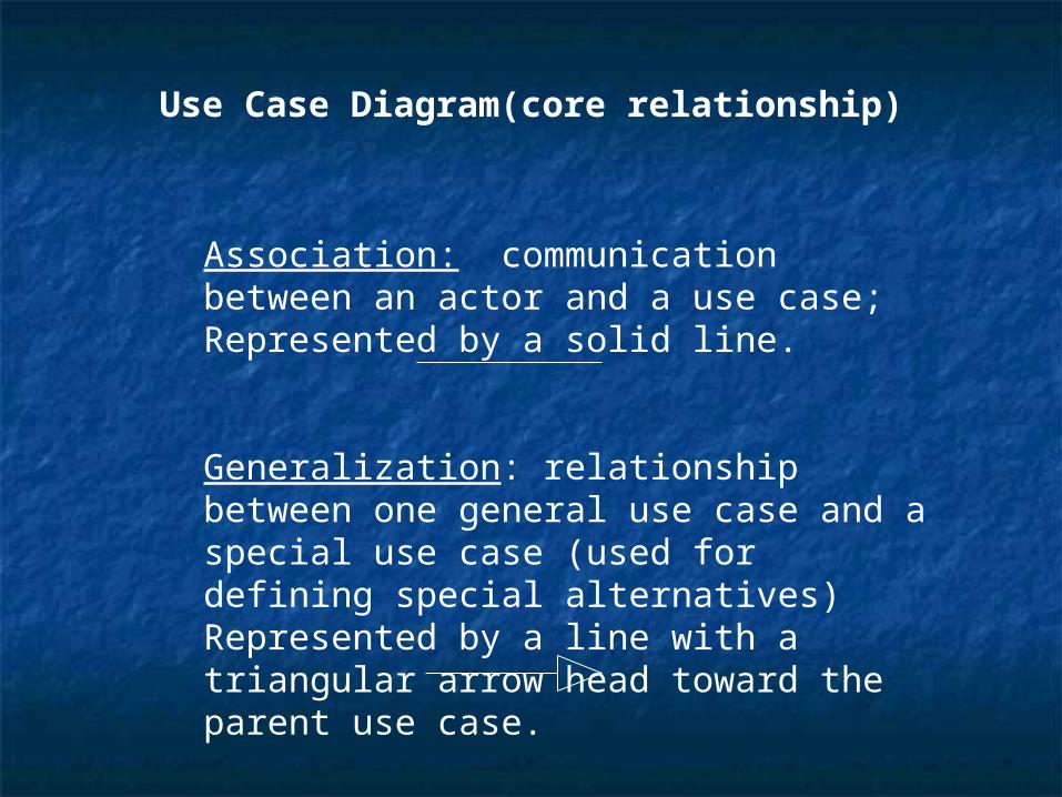
Use Case Diagram(core relationship)
Association: communication between an actor and a use case; Represented by a solid line.
Generalization: relationship between one general use case and a special use case (used for defining special alternatives)Represented by a line with a triangular arrow head toward the parent use case.
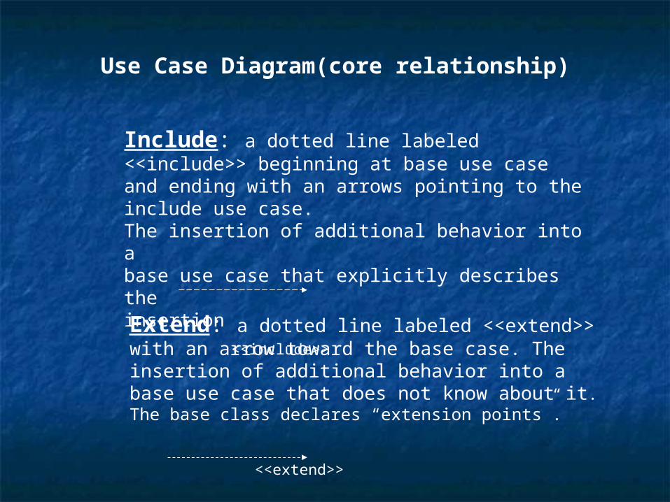
Use Case Diagram(core relationship)
Extend: a dotted line labeled <<extend>> with an arrow toward the base case. The insertion of additional behavior into abase use case that does not know about it. The base class declares “extension points”.
<<extend>>
Include: a dotted line labeled <<include>> beginning at base use case and ending with an arrows pointing to the include use case. The insertion of additional behavior into abase use case that explicitly describes theinsertion
<<include>>
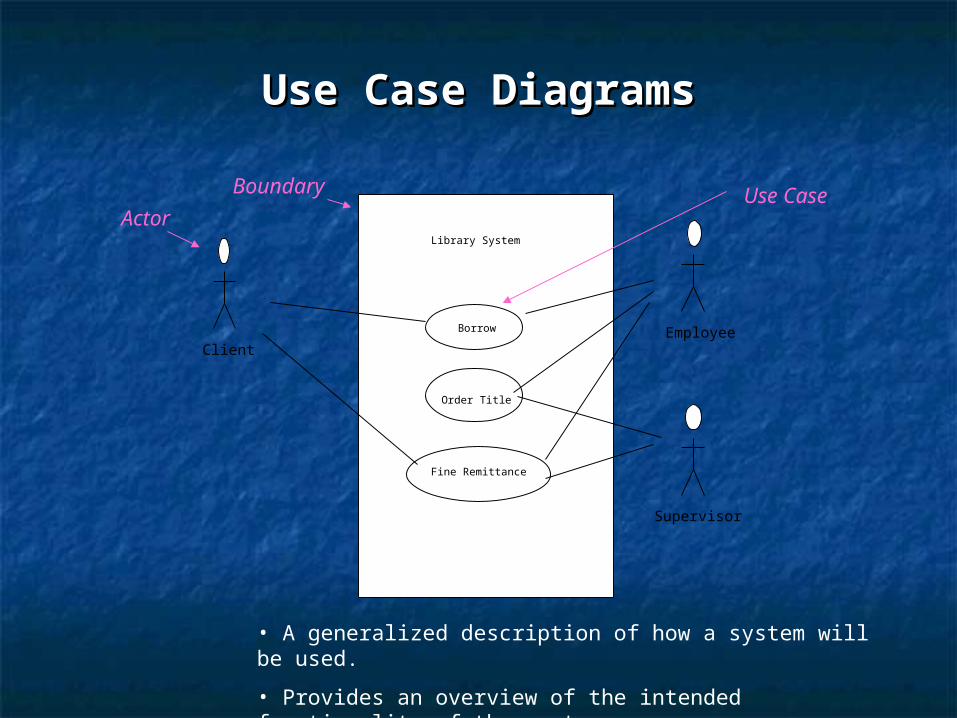
Use Case DiagramsUse Case Diagrams
Library System
Borrow
Order Title
Fine Remittance
ClientEmployee
Supervisor
• A generalized description of how a system will be used.
• Provides an overview of the intended functionality of the system
Boundary
ActorUse Case
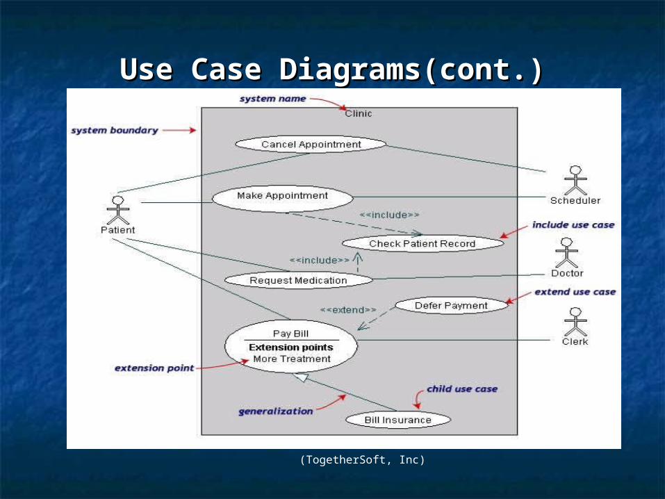
Use Case DiagramsUse Case Diagrams(cont.)(cont.)
(TogetherSoft, Inc)
Use Case DiagramsUse Case Diagrams(cont.)(cont.)
•Pay Bill is a parent use case and Bill Insurance is the child use case. (generalization)
•Both Make Appointment and Request Medication include Check Patient Record as a subtask.(include)
•The extension point is written inside the base casePay bill; the extending class Defer payment adds the behavior of this extension point. (extend)
Class diagramClass diagram A class is a collection of objects with common A class is a collection of objects with common
structure, common behavior, common structure, common behavior, common relationships and common semanticsrelationships and common semantics
Classes are found by examining the objects in Classes are found by examining the objects in sequence and collaboration diagramsequence and collaboration diagram
A class is drawn as a rectangle with three A class is drawn as a rectangle with three compartmentscompartments
Classes should be named using the vocabulary of Classes should be named using the vocabulary of the domainthe domain Naming standards should be createdNaming standards should be created e.g., all classes are singular nouns starting with a capital e.g., all classes are singular nouns starting with a capital
letterletter Detailed class diagrams are used for developersDetailed class diagrams are used for developers
Class representationClass representation
Each class is represented by a rectangle subdivided into Each class is represented by a rectangle subdivided into three compartmentsthree compartments NameName AttributesAttributes OperationsOperations
Modifiers are used to indicate visibility of attributes and Modifiers are used to indicate visibility of attributes and operations.operations. ‘‘+’ is used to denote +’ is used to denote PublicPublic visibility (everyone) visibility (everyone) ‘‘#’ is used to denote #’ is used to denote ProtectedProtected visibility (friends and visibility (friends and
derived)derived) ‘‘-’ is used to denote -’ is used to denote PrivatePrivate visibility (no one) visibility (no one)
By default, attributes are hidden and operations are visible.By default, attributes are hidden and operations are visible.
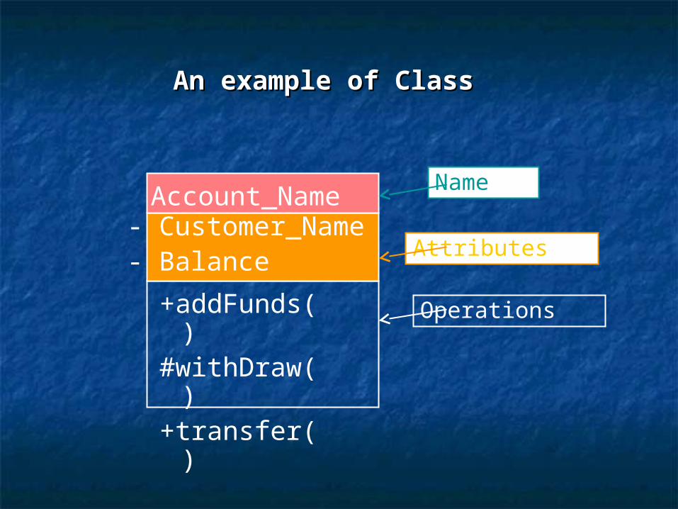
An example of Class An example of Class
Account_Name- Customer_Name- Balance
+addFunds( )#withDraw( )+transfer( )
Name
Attributes
Operations
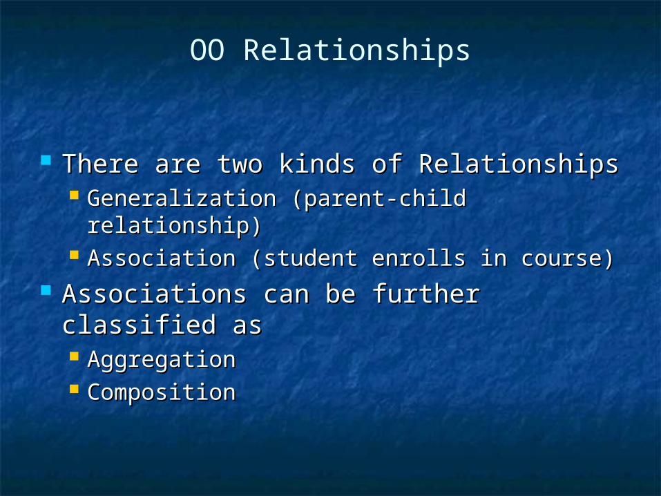
OO Relationships
There are two kinds of RelationshipsThere are two kinds of Relationships Generalization (parent-child Generalization (parent-child
relationship)relationship) Association (student enrolls in course)Association (student enrolls in course)
Associations can be further classified Associations can be further classified asas AggregationAggregation CompositionComposition
Subtype2
Supertype
Subtype1
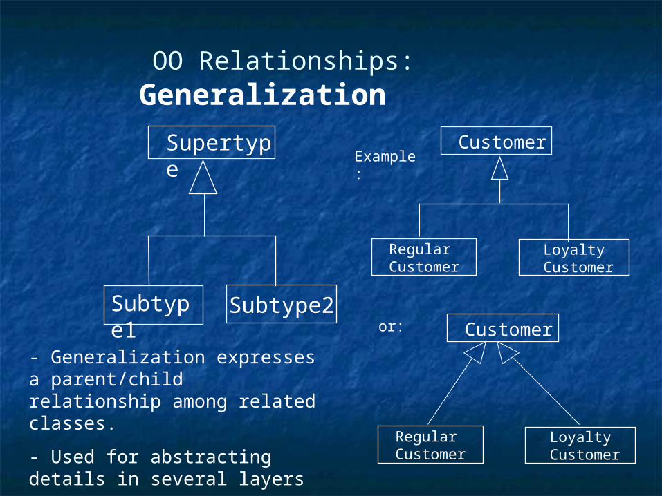
OO Relationships: Generalization
- Generalization expresses a parent/child relationship among related classes.
- Used for abstracting details in several layers
Regular Customer
Loyalty Customer
Customer Example:
Regular Customer
Loyalty Customer
Customer or:
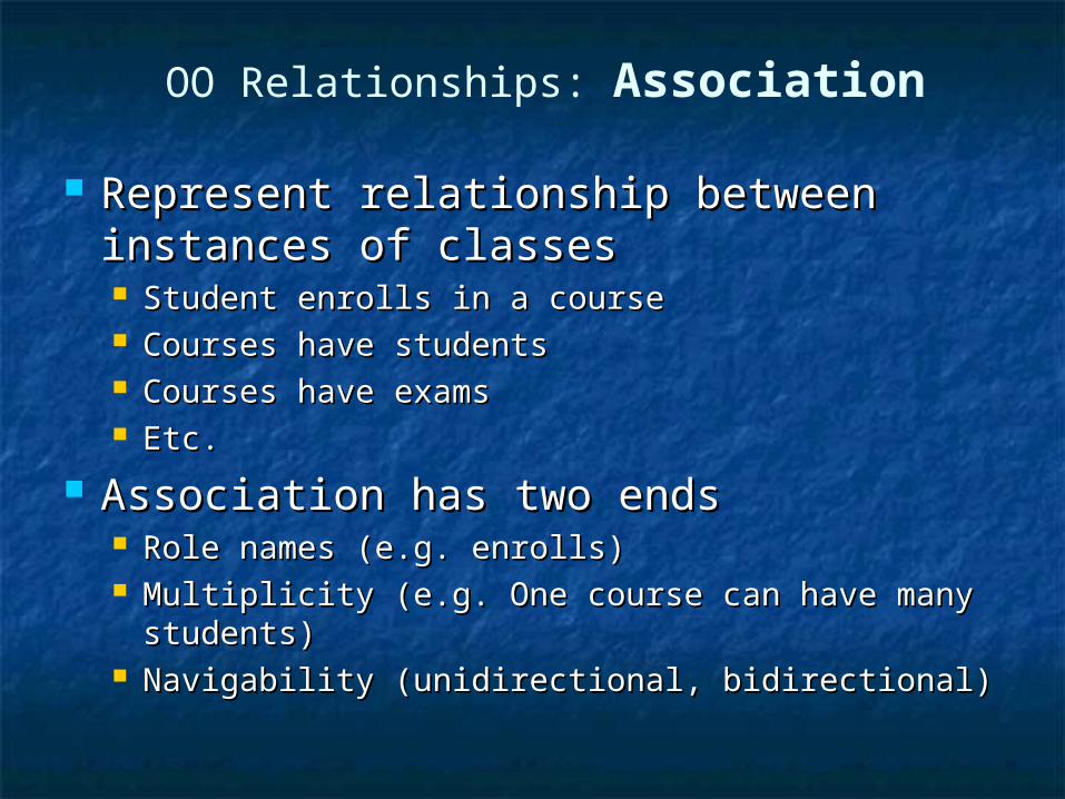
Represent relationship between Represent relationship between instances of classesinstances of classes Student enrolls in a courseStudent enrolls in a course Courses have studentsCourses have students Courses have examsCourses have exams Etc.Etc.
Association has two endsAssociation has two ends Role names (e.g. enrolls)Role names (e.g. enrolls) Multiplicity (e.g. One course can have many Multiplicity (e.g. One course can have many
students)students) Navigability (unidirectional, bidirectional)Navigability (unidirectional, bidirectional)
OO Relationships: Association
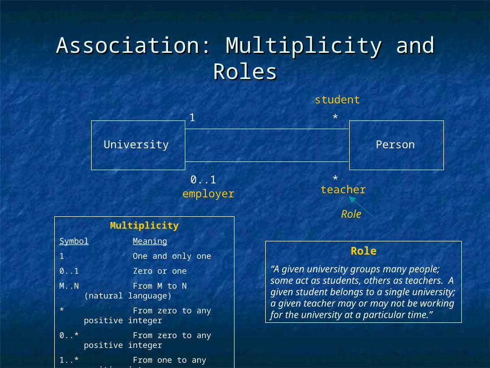
Association: Multiplicity and RolesAssociation: Multiplicity and Roles
University Person
1
0..1
*
*
Multiplicity
Symbol Meaning
1 One and only one
0..1 Zero or one
M..N From M to N (natural language)
* From zero to any positive integer
0..* From zero to any positive integer
1..* From one to any positive integer
teacheremployer
Role
Role
“A given university groups many people; some act as students, others as teachers. A given student belongs to a single university; a given teacher may or may not be working for the university at a particular time.”
student
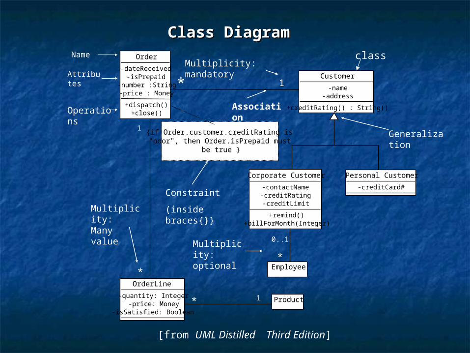
Class DiagramClass DiagramOrder
-dateReceived-isPrepaid
-number :String-price : Money
+dispatch()+close()
Customer
-name-address
+creditRating() : String()
Corporate Customer
-contactName-creditRating-creditLimit
+remind()+billForMonth(Integer)
Personal Customer
-creditCard#
OrderLine
-quantity: Integer-price: Money
-isSatisfied: Boolean
Product* 1
1
*Employee*
{if Order.customer.creditRating is"poor", then Order.isPrepaid must
be true }
* 1
Constraint
(inside braces{}}
Operations
Attributes
Name
Association
Multiplicity: mandatory
Multiplicity: Many value
Multiplicity: optional
Generalization
[from UML Distilled Third Edition]
class
0..1
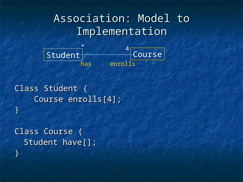
Association: Model to ImplementationAssociation: Model to Implementation
Class Student {Class Student { Course enrolls[4];Course enrolls[4];}}
Class Course {Class Course {Student have[];Student have[];
}}
Student Courseenrollshas
* 4
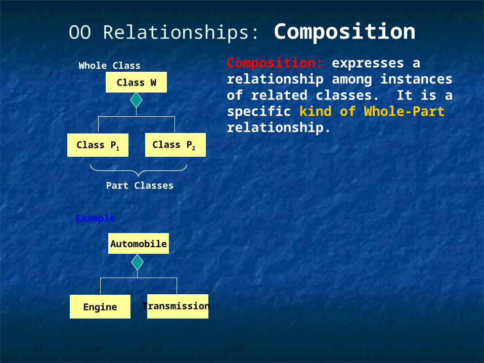
OO Relationships: Composition
Class W
Class P1 Class P2
Composition: expresses a relationship among instances of related classes. It is a specific kind of Whole-Part relationship.
Whole Class
Part Classes
Automobile
Engine Transmission
Example
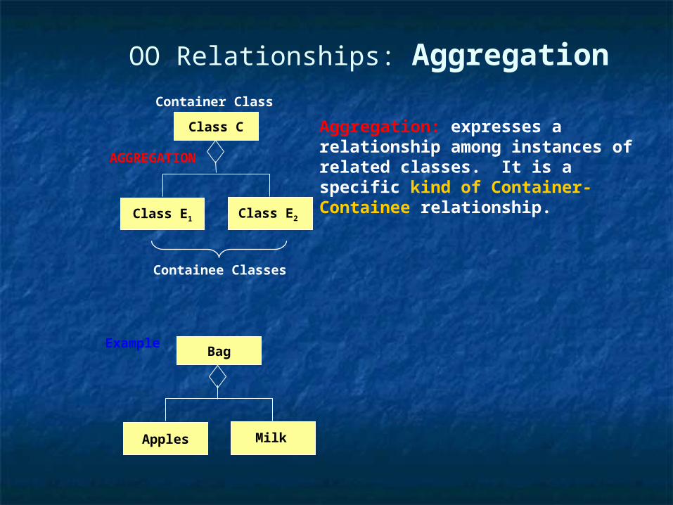
OO Relationships: Aggregation
Class C
Class E1 Class E2
AGGREGATION
Aggregation: expresses a relationship among instances of related classes. It is a specific kind of Container-Containee relationship.
Container Class
Containee Classes
Bag
Apples Milk
Example
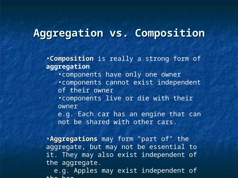
Aggregation vs. CompositionAggregation vs. Composition
•CompositionComposition is really a strong form of aggregation •components have only one owner •components cannot exist independent of their owner •components live or die with their owner e.g. Each car has an engine that can not be shared with other cars.
•AggregationsAggregations may form "part of" the aggregate, but may not be essential to it. They may also exist independent of the aggregate. e.g. Apples may exist independent of the bag.
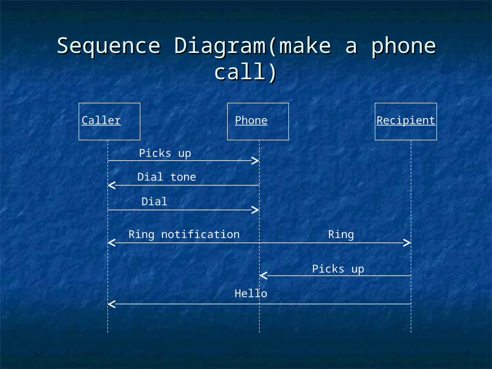
Sequence Diagram(make a phone call)Sequence Diagram(make a phone call)
Caller Phone Recipient
Picks up
Dial tone
Dial
Ring notification Ring
Picks up
Hello
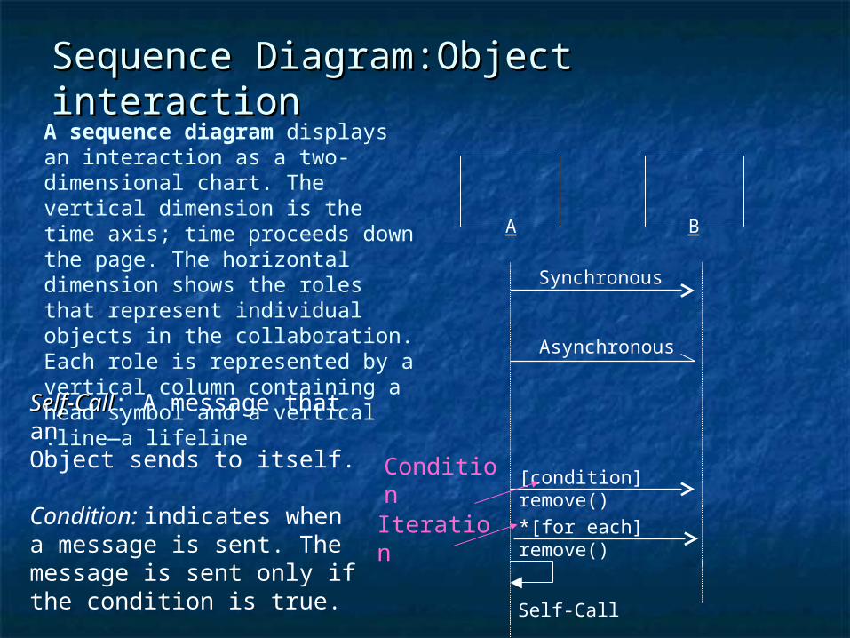
Sequence Diagram:Object interactionSequence Diagram:Object interaction
Self-CallSelf-Call: A message that an Object sends to itself.
Condition: indicates when a message is sent. The message is sent only if the condition is true.
Iteration
Condition
A B
Synchronous
Asynchronous
Self-Call
[condition] remove()
*[for each] remove()
A sequence diagram displays an interaction as a two-dimensional chart. The vertical dimension is the time axis; time proceeds down the page. The horizontal dimension shows the roles that represent individual objects in the collaboration.Each role is represented by a vertical column containing a head symbol and a vertical line—a lifeline.
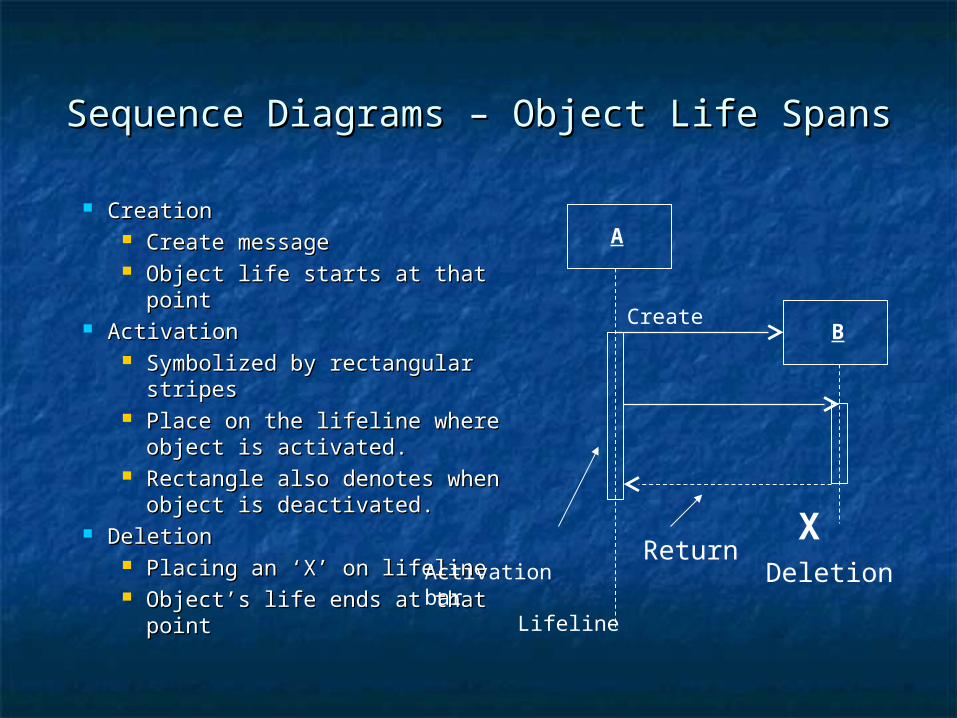
Sequence Diagrams – Object Life SpansSequence Diagrams – Object Life Spans
CreationCreation Create messageCreate message Object life starts at that pointObject life starts at that point
ActivationActivation Symbolized by rectangular Symbolized by rectangular
stripesstripes Place on the lifeline where Place on the lifeline where
object is activated.object is activated. Rectangle also denotes when Rectangle also denotes when
object is deactivated.object is deactivated. DeletionDeletion
Placing an ‘X’ on lifelinePlacing an ‘X’ on lifeline Object’s life ends at that pointObject’s life ends at that point
Activation bar
A
BCreate
XDeletion
Return
Lifeline
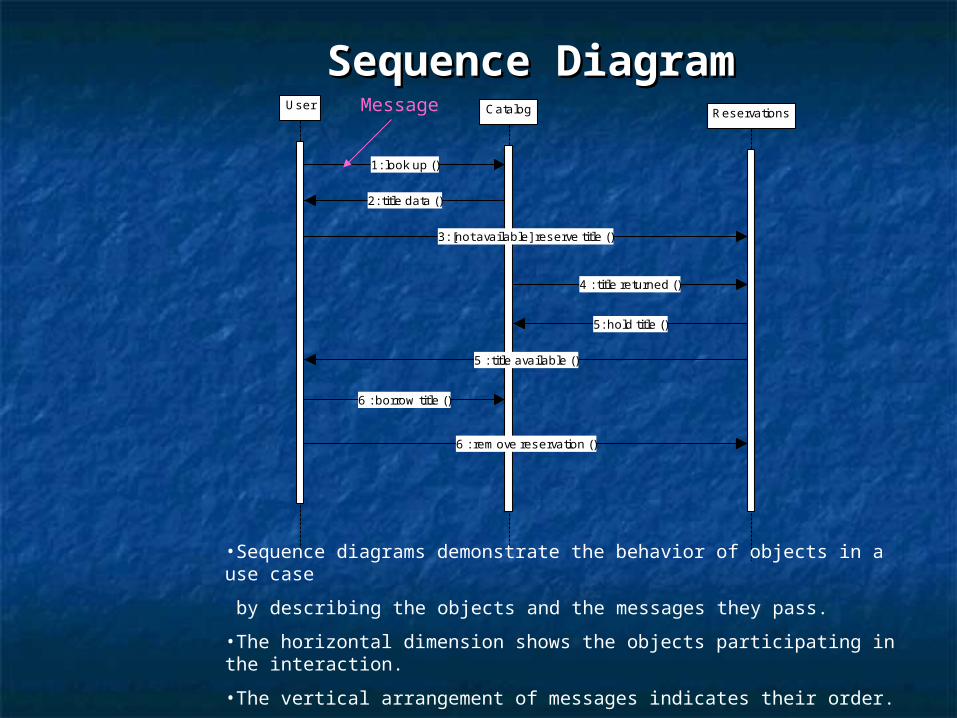
Sequence DiagramSequence DiagramUser Catalog Reservations
1: look up ()
2: title data ()
3: [not available] reserve title ()
4 : title returned ()
5: hold title ()
5 : title available ()
6 : borrow title ()
6 : rem ove reservation ()
•Sequence diagrams demonstrate the behavior of objects in a use case
by describing the objects and the messages they pass.
•The horizontal dimension shows the objects participating in the interaction.
•The vertical arrangement of messages indicates their order.
•The labels may contain the seq. # to indicate concurrency.
Message
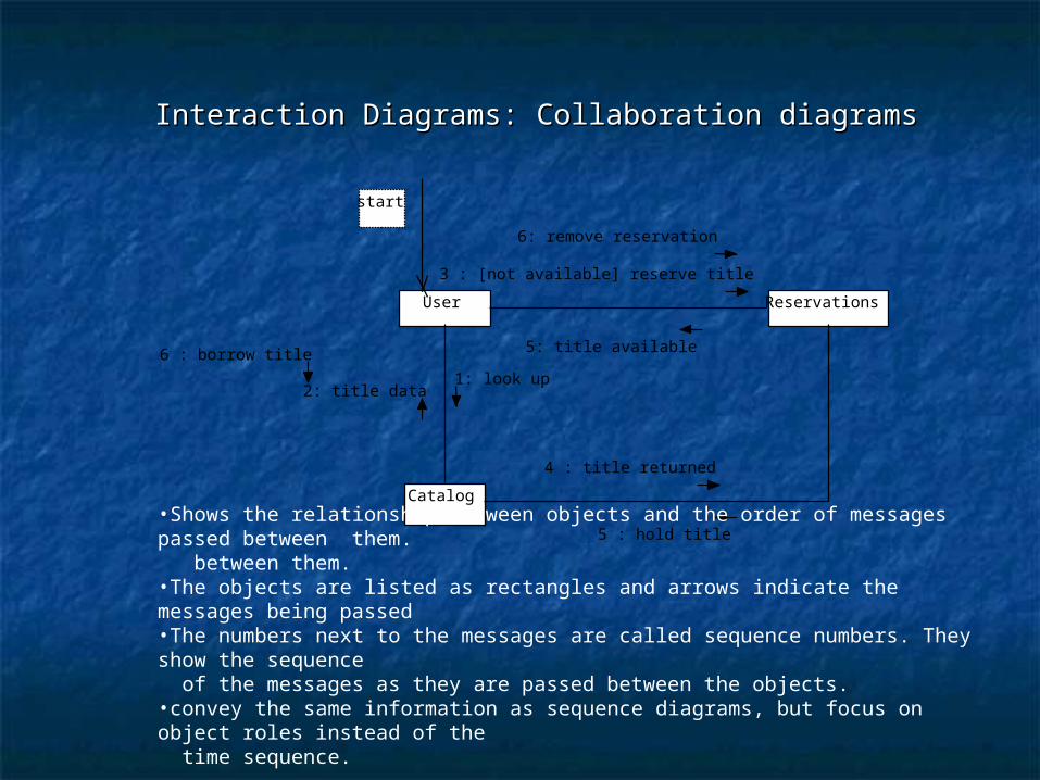
Interaction Diagrams: Collaboration diagramsInteraction Diagrams: Collaboration diagrams
User
Catalog
Reservations
start
1: look up2: title data
3 : [not available] reserve title
4 : title returned
5 : hold title
6 : borrow title
6: remove reservation
5: title available
•Shows the relationship between objects and the order of messages passed between them. between them. •The objects are listed as rectangles and arrows indicate the messages being passed •The numbers next to the messages are called sequence numbers. They show the sequence of the messages as they are passed between the objects. •convey the same information as sequence diagrams, but focus on object roles instead of the time sequence.
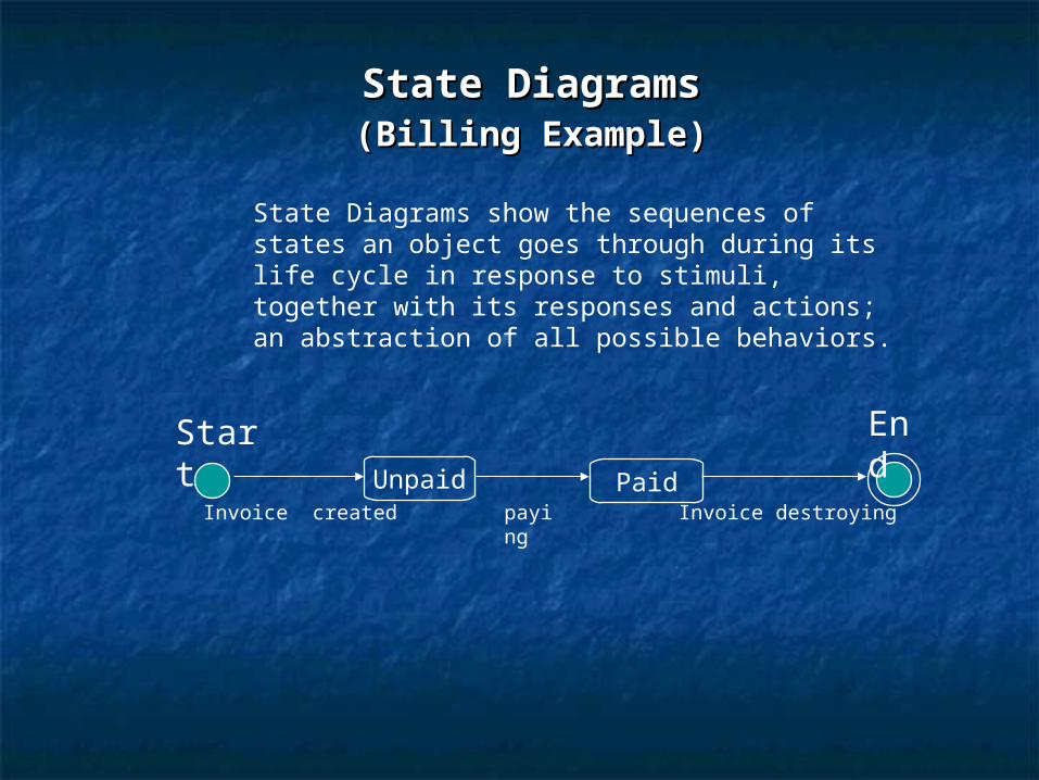
State DiagramsState Diagrams ((Billing Example)Billing Example)
State Diagrams show the sequences of states an object goes through during its life cycle in response to stimuli, together with its responses and actions; an abstraction of all possible behaviors.
Unpaid
Start End
PaidInvoice created payin
gInvoice destroying
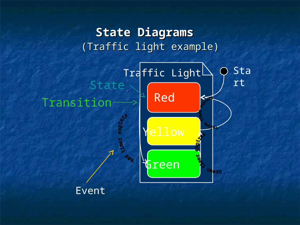
State DiagramsState Diagrams (Traffic light example)(Traffic light example)
Yellow
Red
Green
Traffic LightState
Transition
Event
Start
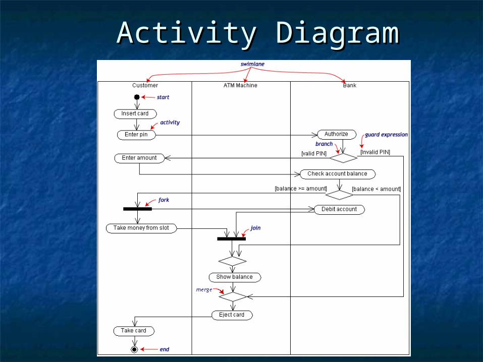
Activity DiagramActivity Diagram
Activity DiagramActivity Diagram
Built during analysis and designBuilt during analysis and design PurposePurpose
Model business workflowsModel business workflows Model operationsModel operations
Developed by analysts, designers Developed by analysts, designers and implementersand implementers
The Physical ModelThe Physical Model The The component diagram component diagram shows the shows the
relationship between software relationship between software components, their dependencies, components, their dependencies, communication, location and other communication, location and other conditions.conditions.
A A deployment diagramdeployment diagram illustrates the illustrates the physical deployment of the system into a physical deployment of the system into a production (or test) environment. It shows production (or test) environment. It shows where components will be located, on where components will be located, on what servers, machines or hardware. It what servers, machines or hardware. It may illustrate network links, LAN may illustrate network links, LAN bandwidth & etc.bandwidth & etc.
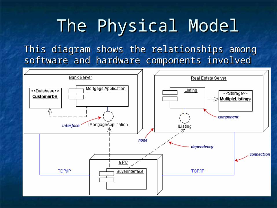
The Physical ModelThe Physical ModelThis diagram shows the relationships among This diagram shows the relationships among software and hardware components involved in real software and hardware components involved in real estate transactions. estate transactions.
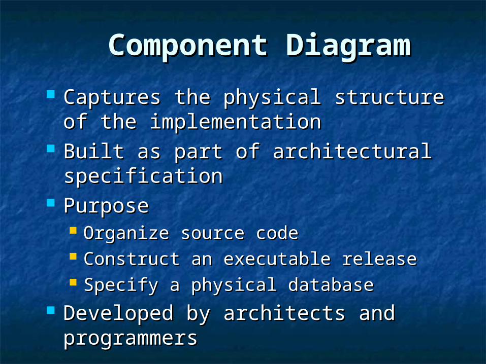
Component DiagramComponent Diagram
Captures the physical structure of the Captures the physical structure of the implementationimplementation
Built as part of architectural Built as part of architectural specificationspecification
PurposePurpose Organize source codeOrganize source code Construct an executable releaseConstruct an executable release Specify a physical databaseSpecify a physical database
Developed by architects and Developed by architects and programmersprogrammers
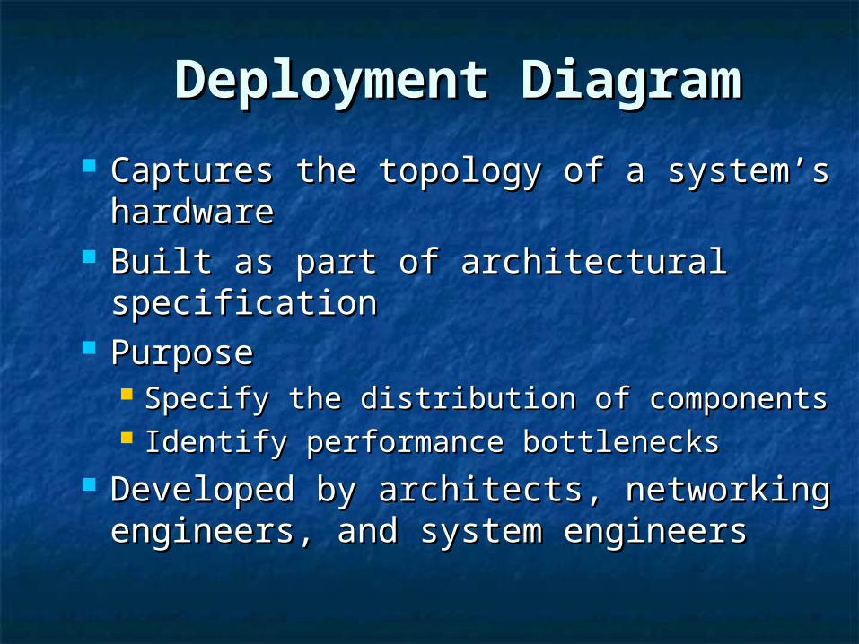
Deployment DiagramDeployment Diagram
Captures the topology of a system’s Captures the topology of a system’s hardwarehardware
Built as part of architectural Built as part of architectural specificationspecification
PurposePurpose Specify the distribution of componentsSpecify the distribution of components Identify performance bottlenecksIdentify performance bottlenecks
Developed by architects, networking Developed by architects, networking engineers, and system engineersengineers, and system engineers
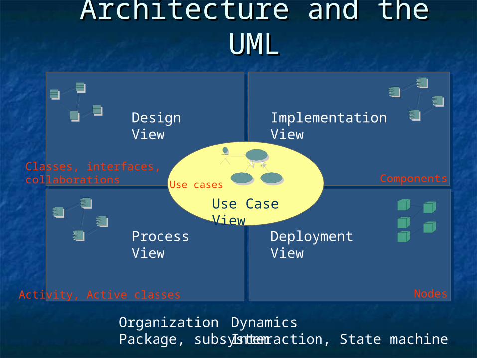
Architecture and the UMLArchitecture and the UML
OrganizationPackage, subsystem
DynamicsInteraction, State machine
Design View Implementation View
Process View
Components Classes, interfaces,collaborations
Activity, Active classes
Deployment View
Nodes
Use Case ViewUse cases