clippard instrument laboratory, inc. data sheets... · clippard instrument laboratory, inc. ... the...
TRANSCRIPT

Clippard Instrument Laboratory, Inc. (513) 521-4261 www.clippard.com
Clippard Instrument Laboratory, Inc.
Clippard is a family owned and operated company. There arecurrently six family members, second and third generation, workingthere. The family emphasis extends to all employees and dictates allcompany policies. Quality is stressed as a matter of pride and familysupport of co-workers. Company goals are not business school imperatives but basic family values: honesty,fairness, strength, compassion, and mutual respect. This translates to our products and customers as quality,performance, service, and value. It translates to our community as a company that supports local activitiesand charities, and is known as a “good place to work.”
The people of Clippard have many unique talents and abilities. They havebuilt a wealth of experience in all aspects of miniature pneumatics. Thecompany’s headquarters are located in Cincinnati, Ohio. All sales andcorporate offices are housed there as well as the manufacture of valves,modules, and fittings. Clippard runs over twenty-five automatic screwmachines and twelve CNC machining centers to make most of its component
parts. Some parts are also purchased from carefully selected vendors, most of which have a long termrelationship with Clippard. Extensive secondary operations and assembly complete the core of manufacturing.The unique aspect is the extensive use of Clippard products on all machinery, fixtures, and jigs throughout theplant, most of which are custom made in Clippard’s own shop. Clippard Minimatics® are widely used to speedand improve production. Few other manufacturers can demonstrate such an earnest commitment to the valueof their own products.
In nearby Fairfield, Ohio, Clippard built a new plant in 1998 to manufactureelectronic interface valves and air cylinders. Situated on 16.9, acres this facility hasplenty of room for growth. In Madison, Indiana, a small subsidiary makes acrylicmodular circuit subplates. The fourth Clippard facilityis four thousand miles away, a sales and distributioncenter, Clippard Europe S.A., in Belgium.
Visitors to the Clippard plants are most impressed not just with machines andfacilities, but with the people. Indeed these achievements are not accidental.Clippard has honed its policies and procedures to create a positive andefficient workplace. Things like job enrichment, cross training, safety training, process controls, individualempowerment, and continuing education opportunities have made our work-force second to none.
Clippard Instrument Laboratory, Inc. (513) 521-4261 www.clippard.com
MissionThe people at Clippard recognize the importance of keeping businessand manufacturing thriving in a rapidly changing world economy.Today’s fast-paced, industrial market demands productivity. Bysupplying high quality miniature pneumatic components at affordableprices, along with expert application assistance, Clippard makes thebenefits of increased productivity available to everyone.
Markets ServedClippard’s worldwide distributor network has grown to include offices in 30 countries and throughout theU.S., providing quality components for an unlimited list of applications. From a simple two step machineprocess, to complex automation of sophisticated machinery, Clippard Minimatics are used virtually everywherefor control, interface, sensing, logic, and actuation functions. This broad range of applications spans a varietyof industries including: machinery, packaging, textiles, medical equipment, animation, agriculture, materialhandling, mobile equipment, assembly, recreation, electronics, food processing, coatings, security, chemicals,construction, testing, mining, and many more.
HistoryLeonard Clippard founded Clippard Instrument Laboratory in 1941, (Inc.,1946). The initial product line consisted of electronic test equipment and radiofrequency coils. The manufacturing of these products required machineryemploying the use of small, yet powerful, pneumatic cylinders and valves. Sinceno such products were commercially available, Leonard Clippard designed and built his own.Because the need for these components was widespread, particularly in manufacturing automated fixturing,Clippard presented them as a new product line in 1949. Until his retirement in 1977, Leonard Clippard
continued to be a pioneer in miniature pneumatic components. Today, the company is managed byWilliam L. Clippard, III, president and Robert L. Clippard, vice-president; the Minimatic line hasgrown to include over 5,000 standard products.
Product LinesSome of the many products offered include Minimatic® valves, cylinders, fittings, modular components,push buttons, stainless steel cylinders, electronic manifold cards, circuit analyzers, andprepiped circuit manifold subplates. Special components designed for customer’s OEMapplications are also available.
QualityQuality remains a primary feature with every product Clippard produces. This is achieved through
the excellence in manufacturing practices and craftsmanship that has continued throughout the years. Thehigh standards set by Leonard Clippard, in company relationships with customers, distributors, suppliers. Andemployees continue to be upheld. The company motto, “Quality People, Quality Products,” emphasizes theimportant role every employee plays in maintaining the company’s reputation.
DistributionA fully-trained, professional distributor network markets and supports Clippard products, worldwide. To assurequality performance, close customer contact is maintained through a network of over100 stocking distributors, with over 800 fluid power specialists. Clippard maintainsclose ties with these distributors through special conferences, training seminars, and thecomplete support of the factory sales and service team.
351
SIMPLIFIED SYMBOL SYSTEM
Clippard Instrument Laboratory, Inc. (513) 521-4261 www.clippard.com
The components needed to manufacture andconstruct pneumatic logic control circuits arereadily available, reliable and have been proven incountless applications.The symbols needed to design a pneumatic circuitare few, yet until now no practical rapid symbologyfor the control designer existed. Most of thesymbols available to the designer are too complexto facilitate clear, creative thinking, take too longto record, leave room for significant errors, andgenerally slow down the design process.In an effort to improve both the speed and accuracyof creative design, we offer for your considerationand use this simplified system of symbols fordesigning pneumatic control circuitry.
Basic RequirementsBefore a circuit can be designed, one needs abasic understanding of the various componentsavailable and how they function. This understandingis a requirement for the successful use of anysymbol. To depict these functional concepts,graphic symbols are used.Historically, pneumatic symbols have been overlydetailed and cumbersome. Symbols (such as ANSI)are often used to tell a complete narrative story.The symbols of this type are difficult to usebecause of their complexity. The writing and thereading of them is always lengthy, robbing timefrom creative efforts. As a finished product they areuseful, and tell a great deal about the component,pertinent or otherwise, but they were never intendedfor air logic control designs. To a circuit designersuch symbols are a burden that can slow or derailthe thought process.
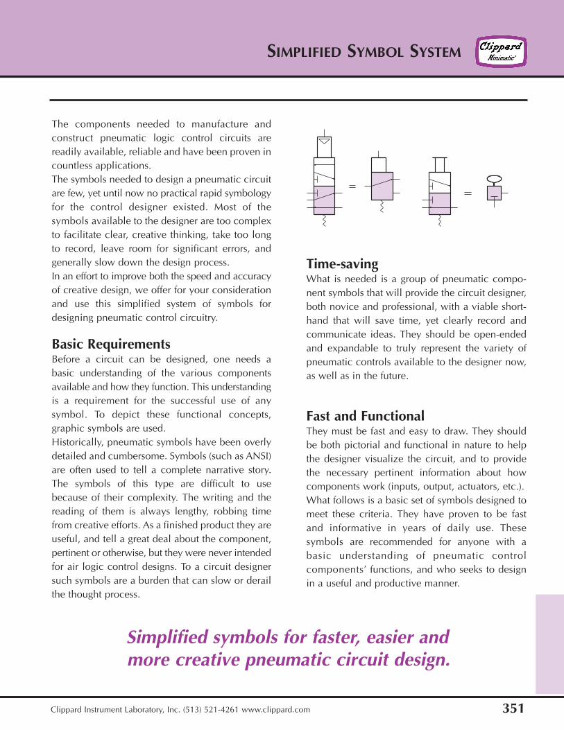
Time-savingWhat is needed is a group of pneumatic compo-nent symbols that will provide the circuit designer,both novice and professional, with a viable short-hand that will save time, yet clearly record andcommunicate ideas. They should be open-endedand expandable to truly represent the variety ofpneumatic controls available to the designer now,as well as in the future.
Fast and FunctionalThey must be fast and easy to draw. They shouldbe both pictorial and functional in nature to helpthe designer visualize the circuit, and to providethe necessary pertinent information about howcomponents work (inputs, output, actuators, etc.).What follows is a basic set of symbols designed tomeet these criteria. They have proven to be fastand informative in years of daily use. Thesesymbols are recommended for anyone with abasic understanding of pneumatic controlcomponents’ functions, and who seeks to designin a useful and productive manner.
Simplified symbols for faster, easier andmore creative pneumatic circuit design.
SIMPLIFIED SYMBOL SYSTEM
352 Clippard Instrument Laboratory, Inc. (513) 521-4261 www.clippard.com
Basic Symbol Groups
Button ToggleCam
Follower Solenoid SinglePilot
DoublePilot
Double PilotSpring Biased
3-WayN.C. Valve
3-WayN.O. Valve
3-WaySelector
Valve
3-WayDiverterValve
4-WayValve
5-Ported4-WayValve
BasicSymbols
Valves
Act
uato
rs
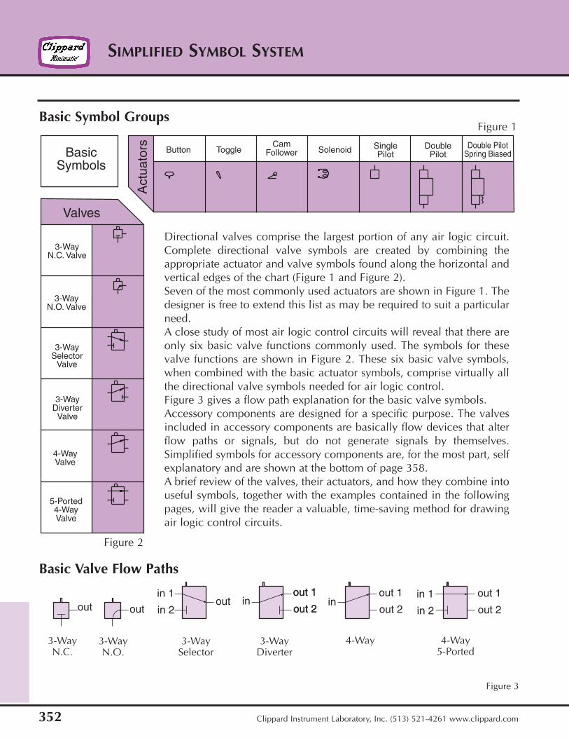
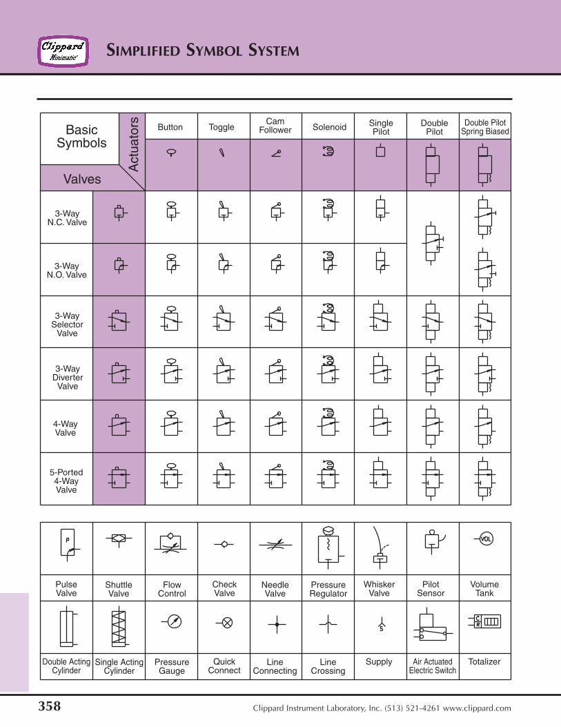
Directional valves comprise the largest portion of any air logic circuit.Complete directional valve symbols are created by combining theappropriate actuator and valve symbols found along the horizontal andvertical edges of the chart (Figure 1 and Figure 2).Seven of the most commonly used actuators are shown in Figure 1. Thedesigner is free to extend this list as may be required to suit a particularneed.A close study of most air logic control circuits will reveal that there areonly six basic valve functions commonly used. The symbols for thesevalve functions are shown in Figure 2. These six basic valve symbols,when combined with the basic actuator symbols, comprise virtually allthe directional valve symbols needed for air logic control.Figure 3 gives a flow path explanation for the basic valve symbols.Accessory components are designed for a specific purpose. The valvesincluded in accessory components are basically flow devices that alterflow paths or signals, but do not generate signals by themselves.Simplified symbols for accessory components are, for the most part, selfexplanatory and are shown at the bottom of page 358.A brief review of the valves, their actuators, and how they combine intouseful symbols, together with the examples contained in the followingpages, will give the reader a valuable, time-saving method for drawingair logic control circuits.
Basic Valve Flow Paths
3-WayN.C.
3-WayN.O.
3-WaySelector
3-WayDiverter
4-Way 4-Way5-Ported
out 1
out 2out out
in 1
in 2out in
out 1
out 2
out 1
out 2
out 1
out 2
in 1
in 2in
Figure 1
Figure 2
Figure 3
353
SIMPLIFIED SYMBOL SYSTEM
Clippard Instrument Laboratory, Inc. (513) 521-4261 www.clippard.com
Button ToggleCam
Follower Solenoid SinglePilot
DoublePilot
Double PilotSpring Biased
3-WayN.C. Valve
3-WayN.O. Valve
3-WaySelector
Valve
3-WayDiverterValve
4-WayValve
5-Ported4-WayValve
BasicSymbols
Valves
Act
uato
rs
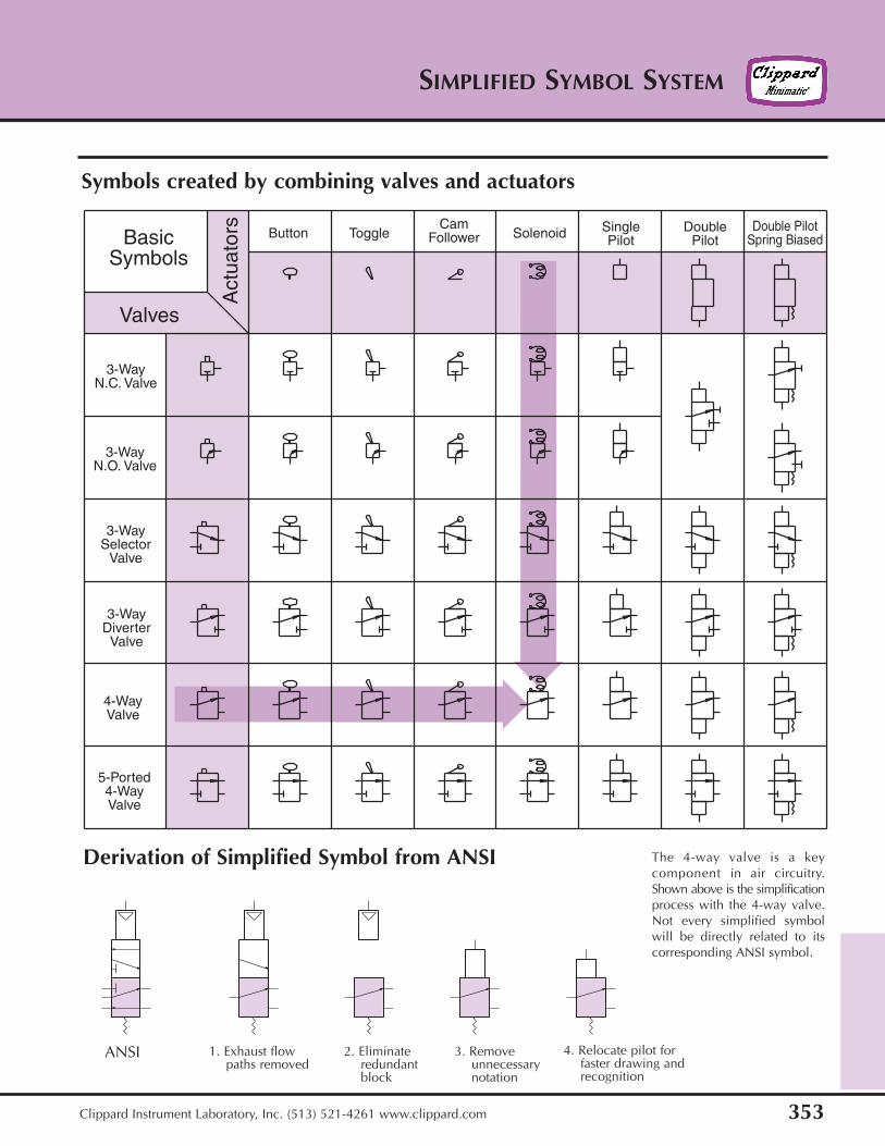
Symbols created by combining valves and actuators
Derivation of Simplified Symbol from ANSI
ANSI 1. Exhaust flow paths removed
2. Eliminate redundantblock
3. Removeunnecessarynotation
4. Relocate pilot forfaster drawing andrecognition
The 4-way valve is a keycomponent in air circuitry.Shown above is the simplificationprocess with the 4-way valve.Not every simplified symbolwill be directly related to itscorresponding ANSI symbol.
SIMPLIFIED SYMBOL SYSTEM
354 Clippard Instrument Laboratory, Inc. (513) 521-4261 www.clippard.com
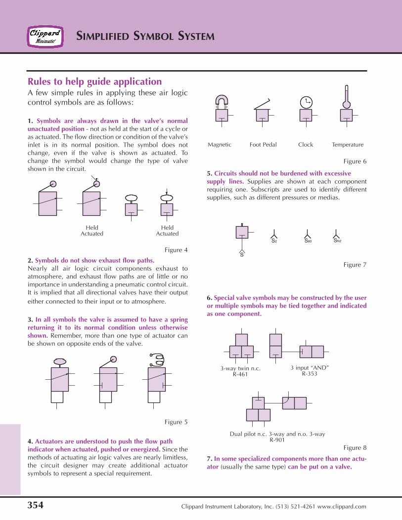
Rules to help guide applicationA few simple rules in applying these air logiccontrol symbols are as follows:
1. Symbols are always drawn in the valve’s normalunactuated position - not as held at the start of a cycle oras actuated. The flow direction or condition of the valve’sinlet is in its normal position. The symbol does notchange, even if the valve is shown as actuated. Tochange the symbol would change the type of valveshown in the circuit.
2. Symbols do not show exhaust flow paths.Nearly all air logic circuit components exhaust toatmosphere, and exhaust flow paths are of little or noimportance in understanding a pneumatic control circuit.It is implied that all directional valves have their outputeither connected to their input or to atmosphere.
3. In all symbols the valve is assumed to have a springreturning it to its normal condition unless otherwiseshown. Remember, more than one type of actuator canbe shown on opposite ends of the valve.
4. Actuators are understood to push the flow pathindicator when actuated, pushed or energized. Since themethods of actuating air logic valves are nearly limitless,the circuit designer may create additional actuatorsymbols to represent a special requirement.
5. Circuits should not be burdened with excessivesupply lines. Supplies are shown at each componentrequiring one. Subscripts are used to identify differentsupplies, such as different pressures or medias.
6. Special valve symbols may be constructed by the useror multiple symbols may be tied together and indicatedas one component.
7. In some specialized components more than one actu-ator (usually the same type) can be put on a valve.
S
S2 S80 SN2
Figure 4
Figure 5
Figure 6
Figure 7
Figure 8
HeldActuated
HeldActuated
Magnetic Foot Pedal Clock Temperature
3-way twin n.c.R-461
3 input “AND”R-353
Dual pilot n.c. 3-way and n.o. 3-wayR-901
355
SIMPLIFIED SYMBOL SYSTEM
Clippard Instrument Laboratory, Inc. (513) 521-4261 www.clippard.com
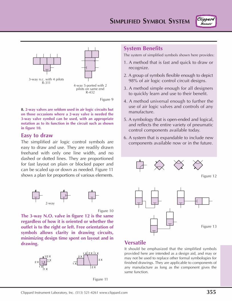
The 3-way N.O. valve in figure 12 is the sameregardless of how it is oriented or whether theoutlet is to the right or left. Free orientation ofsymbols allows clarity in drawing circuits,minimizing design time spent on layout and indrawing.
8. 2-way valves are seldom used in air logic circuits buton those occasions where a 2-way valve is needed the3-way valve symbol can be used, with an appropriatenotation as to its function in the circuit such as shownin figure 10.
Easy to drawThe simplified air logic control symbols areeasy to draw and use. They are readily drawnfreehand with only one line width, and nodashed or dotted lines. They are proportionedfor fast layout on plain or blocked paper andcan be scaled up or down as needed. Figure 11shows a plan for proportions of various elements.
System BenefitsThe system of simplified symbols shown here provides:
1. A method that is fast and quick to draw orrecognize.
2. A group of symbols flexible enough to depict98% of air logic control circuit designs.
3. A method simple enough for all designersto quickly learn and use to their benefit.
4. A method universal enough to further theuse of air logic valves and controls of anymanufacture.
5. A symbology that is open-ended and logical,and reflects the entire variety of pneumaticcontrol components available today.
6. A system that is expandable to include newcomponents available now or in the future.
VersatileIt should be emphasized that the simplified symbolsprovided here are intended as a design aid, and may ormay not be used to replace other formal symbologies forfinished drawings. They are applicable to components ofany manufacture as long as the component gives thesame function.
1/2 X1 X
1 X1 X
1 X2 X1/2X 1 X
2 X1 X 2 X 1 X
2 X
3 X
Figure 9
Figure 10
Figure 11
Figure 12
Figure 13
3-way n.c. with 4 pilotsR-311
4-way 5-ported with 2pilots on same end
R-432
2-way
SIMPLIFIED SYMBOL SYSTEM
356 Clippard Instrument Laboratory, Inc. (513) 521-4261 www.clippard.com
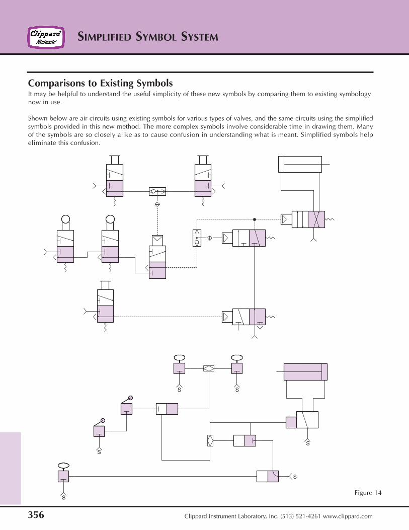
Comparisons to Existing SymbolsIt may be helpful to understand the useful simplicity of these new symbols by comparing them to existing symbologynow in use.
Shown below are air circuits using existing symbols for various types of valves, and the same circuits using the simplifiedsymbols provided in this new method. The more complex symbols involve considerable time in drawing them. Manyof the symbols are so closely alike as to cause confusion in understanding what is meant. Simplified symbols helpeliminate this confusion.
S
S
S S
S
S
Figure 14
357
SIMPLIFIED SYMBOL SYSTEM
Clippard Instrument Laboratory, Inc. (513) 521-4261 www.clippard.com
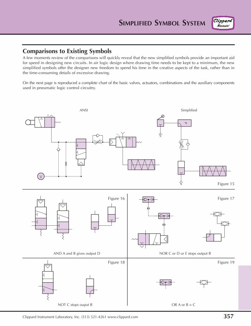
Comparisons to Existing SymbolsA few moments review of the comparisons will quickly reveal that the new simplified symbols provide an important aidfor speed in designing new circuits. In air logic design where drawing time needs to be kept to a minimum, the newsimplified symbols offer the designer new freedom to spend his time in the creative aspects of the task, rather than inthe time-consuming details of excessive drawing.
On the next page is reproduced a complete chart of the basic valves, actuators, combinations and the auxiliary componentsused in pneumatic logic control circuitry.
Figure 15
Figure 16 Figure 17
Figure 18 Figure 19
SimplifiedANSI
AND A and B gives output D NOR C or D or E stops output B
NOT C stops ouput B OR A or B = C
SIMPLIFIED SYMBOL SYSTEM
358 Clippard Instrument Laboratory, Inc. (513) 521-4261 www.clippard.com
Button ToggleCam
Follower Solenoid SinglePilot
DoublePilot
Double PilotSpring Biased
3-WayN.C. Valve
3-WayN.O. Valve
3-WaySelector
Valve
3-WayDiverterValve
4-WayValve
5-Ported4-WayValve
PulseValve
ShuttleValve
FlowControl
CheckValve
NeedleValve
PressureRegulator
WhiskerValve
PilotSensor
VolumeTank
Double ActingCylinder
Single ActingCylinder
PressureGauge
QuickConnect
LineConnecting
LineCrossing
Supply Air ActuatedElectric Switch
Totalizer
BasicSymbols
Valves
Act
uato
rs
359
SIMPLIFIED SYMBOL SYSTEM
Clippard Instrument Laboratory, Inc. (513) 521-4261 www.clippard.com
in mm0.025 0.6350.050 1.2700.075 1.9050.100 2.5400.125 3.1750.150 3.8100.175 4.4450.200 5.0800.225 5.7150.250 6.350
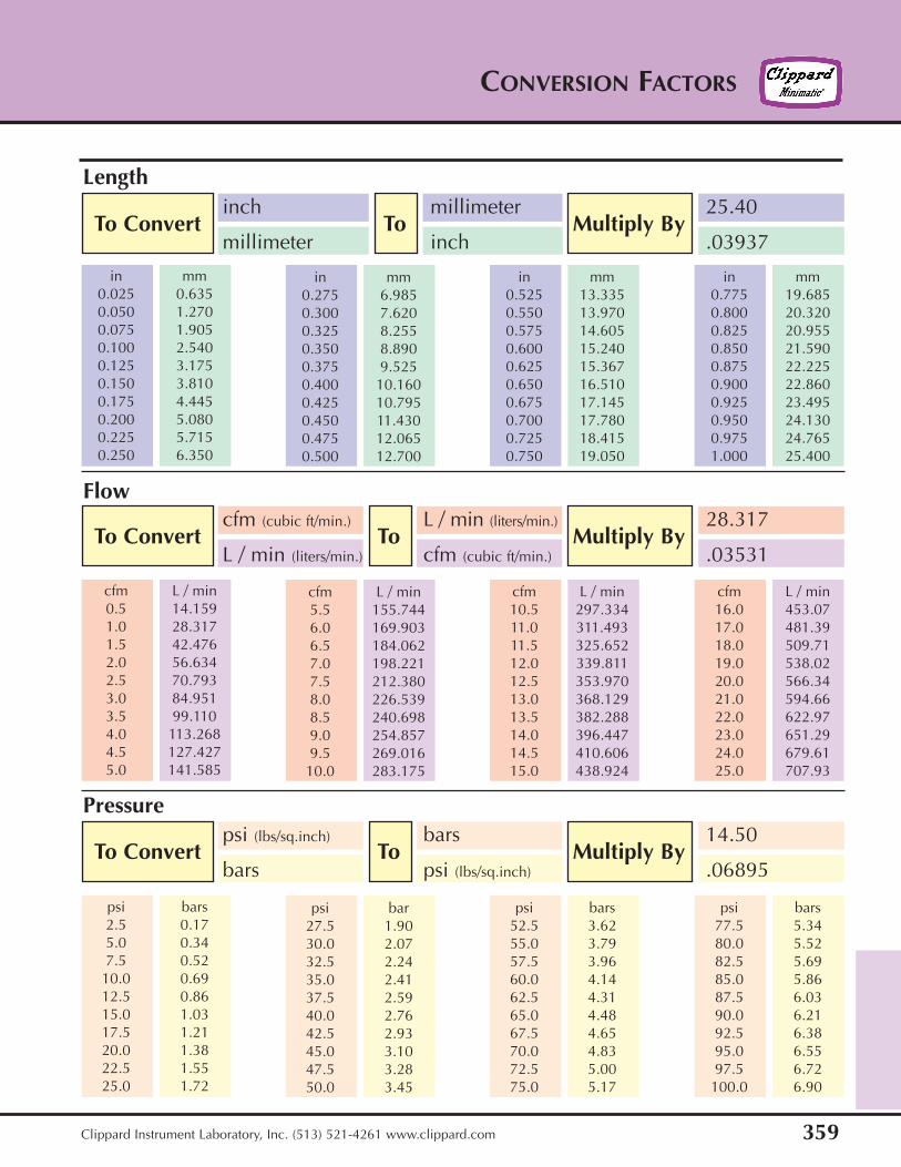
CONVERSION FACTORS
To Convert To Multiply Byinch millimeter 25.40
millimeter inch .03937
To Convert To Multiply Bycfm (cubic ft/min.) L / min (liters/min.) 28.317
L / min (liters/min.) cfm (cubic ft/min.) .03531
To Convert To Multiply Bypsi (lbs/sq.inch) bars 14.50
bars psi (lbs/sq.inch) .06895
in mm0.275 6.9850.300 7.6200.325 8.2550.350 8.8900.375 9.5250.400 10.1600.425 10.7950.450 11.4300.475 12.0650.500 12.700
in mm0.525 13.3350.550 13.9700.575 14.6050.600 15.2400.625 15.3670.650 16.5100.675 17.1450.700 17.7800.725 18.4150.750 19.050
in mm0.775 19.6850.800 20.3200.825 20.9550.850 21.5900.875 22.2250.900 22.8600.925 23.4950.950 24.1300.975 24.7651.000 25.400
cfm L / min0.5 14.1591.0 28.3171.5 42.4762.0 56.6342.5 70.7933.0 84.9513.5 99.1104.0 113.2684.5 127.4275.0 141.585
cfm L / min5.5 155.7446.0 169.9036.5 184.0627.0 198.2217.5 212.3808.0 226.5398.5 240.6989.0 254.8579.5 269.01610.0 283.175
cfm L / min10.5 297.33411.0 311.49311.5 325.65212.0 339.81112.5 353.97013.0 368.12913.5 382.28814.0 396.44714.5 410.60615.0 438.924
cfm L / min16.0 453.0717.0 481.3918.0 509.7119.0 538.0220.0 566.3421.0 594.6622.0 622.9723.0 651.2924.0 679.6125.0 707.93
psi bars2.5 0.175.0 0.347.5 0.5210.0 0.6912.5 0.8615.0 1.0317.5 1.2120.0 1.3822.5 1.5525.0 1.72
psi bar27.5 1.9030.0 2.0732.5 2.2435.0 2.4137.5 2.5940.0 2.7642.5 2.9345.0 3.1047.5 3.2850.0 3.45
psi bars52.5 3.6255.0 3.7957.5 3.9660.0 4.1462.5 4.3165.0 4.4867.5 4.6570.0 4.8372.5 5.0075.0 5.17
psi bars77.5 5.3480.0 5.5282.5 5.6985.0 5.8687.5 6.0390.0 6.2192.5 6.3895.0 6.5597.5 6.72100.0 6.90
Pressure
Flow
Length

SIMPLIFIED SYMBOL SYSTEM
360 Clippard Instrument Laboratory, Inc. (513) 521-4261 www.clippard.com
CONVERSION FACTORS
To Convert To Multiply Bypounds (lbs) newtons (N) 4.448
newtons (N) pounds (lbs) .2248
To Convert To Multiply ByFahrenheit (˚F) Celsius (˚C ) (˚F - 32) /1.8
Celsius (˚C ) Fahrenheit (˚F) 1.8 ˚C + 32
lbs N0.25 1.10.50 2.20.75 3.31.00 4.41.25 5.61.50 6.71.75 7.82.00 8.92.25 10.02.50 11.1
lbs N2.75 12.23.00 13.33.25 14.53.50 15.63.75 16.74.00 17.84.25 18.94.50 20.04.75 21.15.00 22.2
lbs N5.25 23.45.50 24.55.75 25.66.00 26.76.25 27.86.50 28.96.75 30.07.00 31.17.25 32.27.50 33.4
lbs N7.75 34.58.00 35.68.25 36.78.50 37.88.75 38.99.00 40.09.25 41.19.50 42.39.75 43.410.00 44.5
˚F ˚C5 -15.010 -12.215 -9.420 -6.725 -3.930 -1.135 +1.740 +4.445 +7.250 +10.0
˚F ˚C55 +12.860 15.665 18.370 21.175 23.980 26.785 18.990 32.295 35.0100 37.8
˚F ˚C105 +40.6110 43.3115 46.1120 48.9125 51.7130 54.4135 57.2140 60.0145 62.8150 65.6
˚F ˚C155 68.3160 71.1165 73.9170 76.7175 79.4180 82.2185 85.0190 87.8195 90.6200 93.3
Temperature
Force