clock synchronization of distributed, real-time, industrial data
TRANSCRIPT

3
Clock Synchronization of Distributed, Real-Time, Industrial Data Acquisition Systems
Alessandra Flammini and Paolo Ferrari University of Brescia, Dept. of Information Engineering
Italy
1. Introduction
In distributed data acquisition systems for industrial applications, the synchronization of the time references of the nodes is essential to guarantee the right real-time behaviour of the system. All the modern distributed automation plants require a clock synchronization mechanism. The use of distributed architectures in industrial applications based on networks has many benefits, including high system flexibility and scalability. However, this enhancement does not come for free; basically, a high-performance network communication among the nodes is needed and the data exchange across the network requires more complex management software than centralized systems (Felser, 2005). Moreover, a key point in all distributed data acquisition systems is the synchronization of the time reference among the nodes (Eidson & Lee, 2003). A typical automation plant is composed by several distributed nodes, controllers, sensors and actuators that need to sample and control the system in a time coordinated fashion. Considering the real-time applications for data-acquisition, the clock synchronization of the time reference across the network is essential in order to support:
• Data fusion of the measures obtained using distributed data acquisition system and sensors (Proft, 2007).
• Distribute signal processing which takes the “time” into account. • Coordination of the actions across a distributed set of actuators if a control action has to
be taken. • Optimization of the transmission bandwidth in the network, thanks to channel medium
access control such as TDMA (Time Division Multiple Access), for both wired and wireless systems (Ueda & Yakoh, 2004).
The scientific community has proposed several types of synchronization algorithms: some of them are dedicated to wired networks, with different kind of complexity and accuracy; others are specifically dedicated to satisfy the requirements of wireless networks. The aim of this chapter is the definition of basic concepts in the field of clock synchronization in order to better understand the typical applications of clock synchronization techniques to industrial data acquisition systems. This chapter is organized as follows. A brief introduction to essential notions regarding the time keeping and clock performance metrics is provided in Section 2 and 3. Clock synchronization for distributed data acquisition systems are discussed in Section 4. Real
www.intechopen.com

Data Acquisition
42
examples of synchronized data acquisition systems for industrial applications are presented in Section 5 for wired systems and in Section 6 for wireless systems.
2. Clocks and time: a brief introduction
A clock can be considered as composed essentially by two parts. The first part is an oscillating device used to determining the length of the second or other time interval: in other words, the clock frequency. Usually, in a common application, a quartz crystal oscillator is used to provide the reference oscillation to an electronic circuit. On the contrary, in an atomic clock, the oscillation of an electromagnetic signal associated with a quantum transition between two energy levels in an atom has been chosen as reference. The second part is a counter, called also adder or accumulator, that keeps track of the number of seconds or oscillator cycles that have occurred. In theory, if a clock is set perfectly and it has a perfect frequency, it keeps the correct time indefinitely. In practice the clock cannot be set perfectly because of random and systematic variations which are present in any oscillator. Moreover, the clock frequency may change from ideal due to environmental changes. The quality of a clock can be described by means of four measures:
• frequency accuracy;
• frequency stability;
• time accuracy;
• time stability. The frequency of a clock is how well it can realize the defined length of the second. A
commonly-used measure is the normalized frequency departure y(t); since it is calculated as
the change in the time error of a clock divided by the elapsed time t between two
measurements, it is time-dependent and dimensionless. The frequency stability indicates the
change in frequency between two periods of time. The time accuracy means how well a
clock agrees with the Coordinated Universal Time (UTC). The time accuracy is an important
quality for distributed data-acquisition systems, since it is an indicator of the consistency of
time in several places (spatially distributed). Time stability is related both with frequency
stability and with time accuracy, especially in distributed systems. For instance, a clock of a
data acquisition system can lose exactly half a second per month: its time accuracy worsens
half a second per month from the initial setting, but it has perfect frequency stability, and
hence perfect time predictability. Generally speaking if the time or frequency errors of the
clocks may be estimated and compensated, the performance of a distributed acquisition
system based on that clock can be improved.
Besides the qualities of a clock, two other definitions are fundamental for the time keeping
of distributed data acquisition systems: synchronization and syntonization. They are needed
for the development of the methods and theories that rule distributed systems.
Synchronization: the times of distributed clocks are synchronized if their readings are the
same after taking into account the reference frame delay along the distribution system (e.g. a
network). Synchronization needs to be specified to within some level of uncertainty,
sometimes referred as “synchronization accuracy”.
Syntonization: the rates, or frequencies, of clocks are syntonized if the rates are the same
after taking into account the reference frame corrections. Syntonization needs to be specified
to within some level of uncertainty.
www.intechopen.com

Clock Synchronization of Distributed, Real-Time, Industrial Data Acquisition Systems
43
3. Methods and measurements for clock characterization
An ideal clock has an error in each frequency measurement that is random and uncorrelated with any of the previous errors. On the other hand, since the time of a clock results from adding or integrating the frequency of an oscillator, the time errors are also integrated. The time error, xi, for each clock adds all the independent frequency errors. The xi follows the so called random-walk process. The time error at any point in time correlates with the past because it is an accumulation of all the previous errors. Because of the random-walk phenomena, the standard deviation of the time error of a clock is unbounded also in the ideal case. If ┥ is the frequency of the oscillator, the frequency departure is defined as the normalized derivative of the frequency
( )y tυ
υ∂= (1)
The time error x(t) can be expressed in function of its frequency offset:
( ) ( )' '
0
t
x t y t dt= ∫ (2)
The standard deviation is not recommended to measure the frequency instability because
the long-term frequency behaviour of most clocks tends to walk off, and so the standard
deviation appears unbounded. The recommended measures for the instability, both from
IEEE and ITU, are described in the following (Hackmand & Sullivan, 1996; Sullivan et al.,
1990). Three sequential time error measurements of a clock, xn, xn+1, and xn+2, spaced by a
measurement interval ┬ must be considered. The normalized frequency departure averaged
over the n to n+1 interval is given by
( )1n n
n
x xy τ+ −= (3)
or in terms of finite difference notation
nn
xy τ
Δ= (4)
In the same way the average frequency departure for the next interval may be written
11
nn
xy τ ++
Δ= (5)
The instability in this clock for its frequency, averaged over the first ┬ interval to the next ┬ can be represented by the change in frequency:
2
1n
n n n
xy y y τ+
ΔΔ = − = (6)
The sum of the squares of these second differences (6) for n from 1 to N-2, where N is the number of time error measurements in a series for a particular clock, divided by 2(N-2), is
www.intechopen.com
Data Acquisition
44
an estimate of the two-sample variance, ┫y2(┬), also called Allan variance (AVAR) (Allan 1987). AVAR can be written as follow:
( ) ( ) ( )2 22 22
1 1
22y x yσ τ τ= Δ = Δ (7)
where the notation “<>” stands for an infinite time average. The average of the second difference is taken over the entire data length, hence the best confidence on the estimate is obtained for long data record. Allan variance is used as a measure of frequency stability in precision oscillators. The advantage of this variance over the classical variance is that it converges for most of the commonly encountered kinds of noise, whereas the classical variance does not always converge to a finite value. Several different types of noise are used to model the time and frequency noise which is present in any real system: white-noise time or phase modulation (PM); flicker or 1/f PM; random-walk FM; flicker-noise or 1/f FM; and white-noise (random and uncorrelated) frequency modulation (FM). The classical variance is non convergent both for flicker-noise (or 1/f FM) and for random-walk FM noise types, whereas the AVAR is convergent for all the types of noise. Moreover the type and level of noise can be inferred observing the dependence of the variance changing the averaging time ┬; the only exception are the white-noise PM and flicker-noise PM, that have similar dependence to ┬. In order to remove the ambiguity just mentioned for AVAR, the modified two-sample variance, MVAR, is introduced in (Howe, 1995). In equation (7), three time-error readings form the second difference, Δ2xi = xi+2 – 2xi+1 + xi. Replacing the three time-error values with three time-error averages (over adjacent windows of duration ┬), then the MVAR is obtained. Its equation is:
( ) ( )22 2
2
1.
2yMod xσ τ τ= Δ (8)
where the bar notation for x means the average over a windows of duration ┬. In addition to these estimates a new variance measure has been introduced for characterization of network performance. The new time variance, TVAR, takes into account both variance of measurement noise and variance of time and frequency transfer. TVAR can be written as follows:
( ) ( ) ( )2 22 2 21
.3 6
x yMod xτσ τ σ τ= = Δ (9)
where the 6 in the denominator normalizes TVAR in order to be equal to the classical variance on the time residuals in the case of classical white noise PM. The three time domain variances are very useful in order to specify the uncertainty in time and frequency metrology for characterizing the stochastic or random processes in clocks (oscillators, and so on). However, in real cases, the systematic effects may limit the performance of clocks, oscillators and time/frequency transfer. As a result, the specification of uncertainty has to consider both the systematic and the random effects; hence they are usually combined as the square root of the sum of the squares. In precision oscillators often occurs frequency drift, a typical systematic error. Frequency drift occurs, for example, in all crystal oscillators. The time error caused by frequency drift is
www.intechopen.com

Clock Synchronization of Distributed, Real-Time, Industrial Data Acquisition Systems
45
given by ½ Dt2, where t is the time since the clock is both synchronized and syntonized and D = y(t)/t is the amount of the frequency drift. This time error is called the time- interval error (TIE). Frequency drift affects the previous measures with the following relation:
( ) ( ).2
y y
DMod
τσ τ σ τ= = (10)
If ┬ is the time since synchronization and syntonization, the TIE≈1.2 ┫x(┬) because of frequency drift. The time interval error in a network can be adjusted varying the synchronization interval.
4. Clock synchronization for real-time distributed systems
The clocks of devices belonging to distributed data acquisition system can differ after some amount of time (even the clocks are initially set accurately) because of the clock drift due both to the different rate of local oscillators and to environmental perturbations. If a synchronization algorithm is employed in the system to compensate the time error, two
main sources of error remains; the information about the time of a clock degrades due both
to the drifts of the clocks (as before) and to the uncertainty of the delay that the messages
carrying the time take to travel along the distributed network. The drift of the clock usually
is more influent than the message delays in the case the time-carrying communication is
infrequent; with the decrease of the frequency of communication, the uncertainty due to the
clock drift increases, while the uncertainty due to the message delays remains constant. A
trivial solution may be the decrease of the synchronization interval, but any clock
synchronization schemes require the time information obtained through the communication
to be processed. The computation power and the memory required by the synchronization
algorithms must increase with the increase of communication data exchanges. This means a
trade-off between the computational power and the accuracy must be achieved.
The synchronization of the clocks in a network where the time is provided outside the
network is known as external; the synchronization is external even if the source of the
common system time is either a node in the network or not. The external synchronization
requires consistency within the network and in respect to the externally provided system
time. The internal synchronization is the synchronization shared only among the clocks
inside the network, without a predetermined master time.
The synchronization can have a global scope, if the clock synchronization is required in all the nodes of the network or a limited scope if it is required in a subset of nodes only. There are algorithms in which the network nodes exchange synchronization messages without interruption and the time synchronization is continuous. On the contrary, other applications require“on-demand synchronization”; if no synchronization is needed, the communication can be reduced. There are two types of on-demand synchronization: event-triggered on-demand synchronization, used when a node needs a synchronized clock only immediately after the event happened; the time-triggered on-demand synchronization is used for collecting data from several nodes at a given time. Since there is no trigger event, the nodes of the network has to be synchronized at a given time and maintain the synchronization at least until the data acquisition takes place. Such a behaviour can be obtained using the “immediate synchronization”, where nodes receive the command to take
www.intechopen.com

Data Acquisition
46
a sample and time-stamp it, or the “anticipated synchronization”, where the order is to take the sample in a future time. The anticipated synchronization is mandatory when the transfer of command and time cannot be simultaneous to all the involved nodes. Note that the minimum synchronization accuracy required by the anticipated synchronization is related to the time that elapses between the synchronization instant and the programmed event. A good synchronization algorithm for data acquisition systems must estimate both the clock rate (syntonization, as explained before) and the offset from the reference time. Offset estimation is sufficient for data fusion operations, while syntonization is required if time intervals have to be measured. Last, time synchronization can be achieved in two different ways. The clocks can be forced to have the ”same” time at any given moment or each clock has it own time but can transform the timescales of the other clocks. Equal results can be obtained using the two approaches: the first approach requires the same amount of communication across the network, whereas the latter require a huge computational and memory overhead. The time information are exchanged between clocks specifying either a time instant or a time intervals; additional information about the quality of the synchronization (time uncertainty) may be also provided.
4.1 Clock synchronization over packet-switched, wired networks
Several solutions have been proposed in order to synchronize the drift of the local clocks in a distributed system: some of them use dedicated hardware, such as GPS receiver, atomic clock or synchronization signals (e.g. 1-PPS – 1 pulse per second), to compensate drift of local clock. Unfortunately these approaches require a separate network for time distribution, which means extra costs and reduced reliability of the whole system. The most attracting clock synchronization solutions for distributed data acquisition system for industrial applications are the algorithms that can also be used in packet-switched networks, like Ethernet. The most diffused communication protocols are NTP (“Network Time Protocol”) (IETF
RFC1305, 1992) and IEEE 1588 PTP (“Precision Time Protocol”) (IEEE1588, 2002;
IEEE1588V2, 2008). Both solutions have advantages and disadvantages for data acquisition
applications that should be balanced by the analysis of the application requests (timing
performance) and constraints (cost and development time). In some applications the
requested synchronization accuracy is below 1 µs. Typical cases are: electrical and industrial
automation; control systems; and distributed measurement applications for time referenced
data acquisition, also known as timestamping of events. In such situations, the reference hi-
performance system against which the other solutions are compared is the use of a GPS
receiver for each device to be synchronized. GPS can guarantee a high level of accuracy
(≈100 ns) but has the disadvantage of the antenna cabling and placing (especially in an
industrial environment or with indoor application). On the other hand, the use of the same
network that connects the devices and transports process data also for transmitting the time
information is the clever solution.
The Network Time Protocol (NTP) was developed starting in 1985 by the University of Delaware and it is based on UDP transport protocol. NTP implements the Marzullo algorithm (Marzullo, 1984) that gives an optimal value elaborating set of estimates and their confidence intervals. The synchronization accuracy that is usually obtained using NTP (with Internet applications) is on the order of few ms, even if in more controlled scenario (like
www.intechopen.com
Clock Synchronization of Distributed, Real-Time, Industrial Data Acquisition Systems
47
local area networks and ideal conditions) NTP can achieve an accuracy as low as few µs. NTP synchronizes the local clock to UTC, even if it can be used also to distribute any time scale on private sub-networks (uncommon). A simplified version of NTP is the Simple Network Time Protocol (SNTP) used by simpler devices and application thanks to the lower computational power required. The NTP protocol clock sources are hierarchically organized into levels called stratum, and identified by numbers. The stratum indicates the distance of that clock from the reference clock. The top level has the number 0; devices belonging to this stratum are the servers for the stratum 1 devices and so on. Usually, the nodes of a given stratum (e.g. 2) query several servers of the parent stratum (e.g. 1) because the NTP algorithm can extract the best data samples. Querying clock belonging to the same stratum is also possible to improve time accuracy. NTP theoretically supports up to 256 strata, depending on the protocol version. The NTP time has a 64 bit representation, 32 bit for the seconds and 32 bit for the fractional part of the second. NTP uses a client-server synchronization model. The synchronization transaction is initiated by the client that asks a time server. Making the request, the client stores the originate timestamp of the transmitted packet. A server that receives this packet stores the receive timestamp and gives it back into the response packet sent to the client. When the client receives the reply, it logs the receive time to estimate the travelling time of the packet. The propagation time (delay) is estimated to be half of the total delay minus the remote (server) processing time, assuming a symmetrical communication delay. The same time differences can be used for the estimation of the time offset between client and server. The estimate of the current time is more accurate if the round trip time is short and symmetric. The time obtained from the estimation must be validated using a set of “sanity checks” before being used at the application. Usually several exchanges are necessary to reach a valid time estimate. Usually a quite long time (up to few minutes) may be required for NTP convergence. Each NTP server continuously updates an estimate of the quality of its reference clocks together with statistics about its own behaviour. IEEE 1588 PTP (Precision Time Protocol) is a time synchronization protocol developed for
distributed measurement and control systems. It is designed in order to provide
synchronization to systems that require an accuracy higher than NTP. This protocol allows
obtaining a sub-microsecond accuracy if:
• oscillator stability and accuracy has to be such that a second measured by any of the clocks is within ±0.01% of SI second;
• the timestamps have to be taken as close as possible to the hardware;
• the network must support multicast transmission;
• the communication paths have to be symmetric;
• each clock has to be accurately described by well-defined properties. PTP is an external synchronization protocol in which all clocks in the network are
synchronized to the time of a single clock, the grandmaster clock. The clock that provides
the time to a sub-network is called master clock whereas the others are called slave clocks.
PTP achieves time synchronization in two steps: first, the clocks in the network are
organized into a master-slaves hierarchy, and then the nodes start to exchange timestamped
messages between master and slave clocks.
Each clock participating in an IEEE 1588 synchronization is described using several properties, such as its stratum, identifier, and variance. The stratum represents the
www.intechopen.com

Data Acquisition
48
synchronization capabilities of the clock to UTC by means of protocols other than PTP (such as NTP or GPS). The identifier represents the accuracy of synchronization to UTC. The variance gives the stability and noise properties of the local oscillator. During the first step of the protocol, each clock broadcasts its properties to the other clocks in its time domain. These information are used by the Best Master Clock (BMC) algorithm which is running independently in any nodes, and is used in order to determine the best clock of the current time domain. The best clock becomes the master whereas the rest become slave clocks. The BMC algorithm arranges the local network in a clear master-slaves hierarchy as shown in Fig. 1 An ordinary clock interfaces with only one broadcast domain and can act as a master or slave in the domain. On the other hand, boundary clock interfaces with more than one broadcast domain but acts as a slave in only one of the domains, and as master in the others.
Fig. 1. The clocks hierarchy in a IEEE 1588 synchronization network.
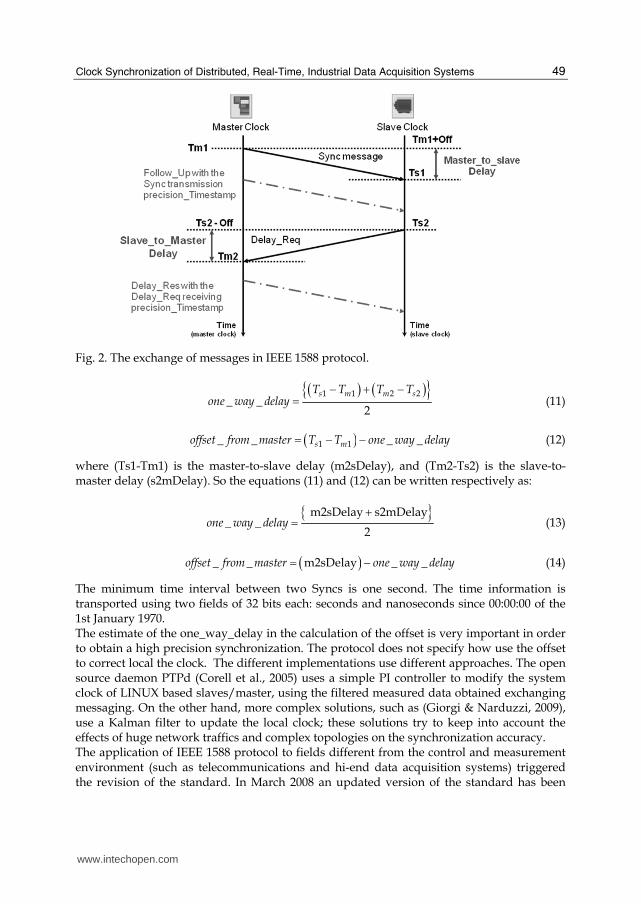
IEEE 1588 provides for five types of messages: Sync, Follow_Up, Delay_Req, Delay_Resp, and Management messages. Sync and Follow_Up messages are transmitted by the master clock so the slaves can calculate their time offset from the master time. The Follow Up message is used to transport the timestamp of the preceding Sync message. The Delay_Req message is transmitted by a slave clock in order to estimate the one way delay due to the communication channel. The Delay_Resp message is transmitted by the master clock in response to the Delay_Req message; it contains the time in which the Delay_Req message has been received from the master. The management messages are used to configure and manage the clocks. IEEE 1588 protocol specifies two message models for synchronization: a “two steps” model and a “one step” model. The exchange of messages is shown in Fig. 2. The grandmaster clock is an ordinary clock that acts as a master clock in the sub-network. In the two steps model, the master sends a Sync message to all the slave clocks in the time domain every sync period. The time in which the Sync message has been sent, Tm1, is transported to the slave clocks in a following Follow Up message. When a slave clock receives the Sync message, it timestamps the time of reception Ts1, according to its local clock. In the same way, the slave clock sends a Delay_Req message to its master and registers the time of transmission, Ts2. The master responds with a Delay_Resp message that contains the time in which the Delay_Req message has been received, Tm2. The one step model for the exchange of the messages is similar except that the Sync message carries the transmission timestamp in order to eliminate the need of the Follow Up message. The phase offset of the slave clock from the master is called offset_from_master, and the one-way delay (one_way_delay) due to the communication path is symmetric. These two parameters can be calculated as:
www.intechopen.com
Clock Synchronization of Distributed, Real-Time, Industrial Data Acquisition Systems
49
Fig. 2. The exchange of messages in IEEE 1588 protocol.
( ) ( ){ }1 1 2 2
_ _2
s m m sT T T Tone way delay
− + −= (11)
( )1 1_ _ _ _s moffset from master T T one way delay= − − (12)
where (Ts1-Tm1) is the master-to-slave delay (m2sDelay), and (Tm2-Ts2) is the slave-to-master delay (s2mDelay). So the equations (11) and (12) can be written respectively as:
{ }m2sDelay s2mDelay
_ _2
one way delay+= (13)
( )_ _ m2sDelay _ _offset from master one way delay= − (14)
The minimum time interval between two Syncs is one second. The time information is transported using two fields of 32 bits each: seconds and nanoseconds since 00:00:00 of the 1st January 1970. The estimate of the one_way_delay in the calculation of the offset is very important in order to obtain a high precision synchronization. The protocol does not specify how use the offset to correct local the clock. The different implementations use different approaches. The open source daemon PTPd (Corell et al., 2005) uses a simple PI controller to modify the system clock of LINUX based slaves/master, using the filtered measured data obtained exchanging messaging. On the other hand, more complex solutions, such as (Giorgi & Narduzzi, 2009), use a Kalman filter to update the local clock; these solutions try to keep into account the effects of huge network traffics and complex topologies on the synchronization accuracy. The application of IEEE 1588 protocol to fields different from the control and measurement environment (such as telecommunications and hi-end data acquisition systems) triggered the revision of the standard. In March 2008 an updated version of the standard has been
www.intechopen.com
Data Acquisition
50
approved; this version of the protocol is known as IEEE 1588 Version 2. This version introduces in the PTP standard several improvements in order to adapt the synchronization protocol to different application scenarios. Unfortunately this new version of the standard is not directly interoperable with the previous version. A new class of devices has been introduces, the so called transparent clocks. A transparent clock is used to connect together two links of a network. This device has been introduced into PTP architecture in order to prevent error accumulation in cascaded topologies using the boundary clocks defined in PTP Version 1. Boundary clocks employ a servo loop to recover the clock on the slave port, and then the recovered clock is used by the other PTP master ports. The cascade of multiple boundary clocks within a network can degrade clock accuracy of the system because of the cumulative effect of multiple servo loops. The quality of the crystal oscillator used in a boundary clock can also impact the accuracy of the PTP clocks in the system. On the other hand, the transparent clocks are used to update and append a timing correction field into PTP payload. The correction field is updated with a value that represents the "residence time" of the message to pass through the transparent clock. In this way each switch appears as a wire because does not alter the time calculation for packets passing through them. The correction field accumulates the value of the residence times of all the cascaded transparent clocks between Master and Slave. The other devices, ordinary and boundary clocks, take into account the value of the correction field in their calculations. In this way the jitter is reduced and the accuracy and stability of the clocks can be increased. Two kinds of transparent clocks are provided from the standard: the end-to-end (E2E) and the peer-to-peer (P2P) transparent clock. In the P2P transparent clocks each port of the node computes the peer link path delay with its link partner on another P2P node. The link path delay calculation is obtained through newly defined V2 messages: PDelay_Req, PDelay_Resp, and PDelay_Resp_Follow_Up. P2P transparent clocks add the link path delay time estimated into the value in the correction field (in addition to the residence time of the message). P2P transparent clocks can work only with nodes (including ordinary and boundary clocks) that support the peer delay function. The size of sync messages has been reduced in order to improve the efficiency of the
protocol, reducing the synchronization information transmitted each sync period. The
structure of the Sync messages has been modified and it is incompatible with previous
version. In order to increase the precision that can be obtained using the PTP, the length of
the timestamp field has been increased. In this way a sub-nanosecond accuracy can be
obtained. The PTP messages can also be directly carried by layer 2 messages (such as
Ethernet), reducing bandwidth occupied by PTP protocol. The synchronization interval can
be dynamically changed during the synchronization, and the sync rate can be faster (more
than 1000 time per second) than previous one.
The application of PTP in different environment other than the measurement applications
requires the addition of several features to enhance the “strength” of the protocol. In
particular the PTP2008, supports fault tolerant architecture that is needed in order to ensure
that no single network element failure can cause clocks to fail in their synchronization. In a
system with redundant grandmasters, the redundant grandmaster must be able to detect
failure of the first grandmaster, and the ordinary clocks must be able to switch from one
grandmaster to another without incurring in an unacceptable frequency or phase jumps.
Fault tolerance is critical in telecom applications and many data acquisition applications,
where safety and reliability are required (De Dominicis et al., 2010a).
www.intechopen.com

Clock Synchronization of Distributed, Real-Time, Industrial Data Acquisition Systems
51
4.2 Clock synchronization over wireless networks
In the last years, wireless networks are becoming very popular. The high flexibility of wireless solutions allows the creation of innovative data acquisition systems to monitor a great number of quantities. Moreover, the data logging over a wide area can be done by means of wireless distributed data acquisition systems. Generally speaking, a wireless distributed data acquisition system is composed by a large number, often variable, of autonomous nodes distributed in the environment. Usually, the devices used to develop a wireless network should be: low-cost; ruggedized; low power; smart and with high computational power. For instance IEEE802.15.4 devices can satisfy large part of these requests and they are widely used to implement wireless distributed acquisition applications. Besides helping in data fusion of measures, the synchronization of wireless network is useful both for reducing the power consumption of each node and for improving the medium access control. For instance the synchronized node can transmit/receive during its time slot, while it remains in low power idle the rest of the time. The traditional protocols cannot be used because of: the low energy available in the nodes; limited storage capabilities; and limited communication capabilities. Synchronization algorithms for wired networks require the exchange of a large amount of messages, and the continuous listening of synchronization messages. Moreover, the number of active nodes and the network topology of a wireless network may vary frequently and unpredictably. For instance, such situations can lead to unstable estimation of the end to end delay of a message. For all these reasons, in the last years special synchronization protocols have been developed. With respect to wired networks, the number of wireless synchronization protocols is quite high. In the following, a very short overview of the most important synchronization algorithms that can be used for wireless distributed data acquisition systems is provided. Timestamp Synchronization (TSS) (Römer, 2001) provides an on-demand, internal synchronization scheme. The clocks run without synchronization and the event timestamps are valid within the node that generated them. If timestamped data are sent to another node a timescale transformation occurs in the receiver (multiple hops imply multiple transformations). The timestamp transformation is obtained subtracting the age of the data from its time of arrival. The age is the time elapsed since its creation. The age of a timestamp consists of two components: the time the timestamp stays in the nodes along the path, and the total amount of time needed to transfer the timestamp from node to node. The first component is measured in the local unsynchronized timescale, while the second component is estimated using the round-trip time of the message and its acknowledgment. Using such a bidirectional message exchange, the receiver can estimate upper bound and lower bound of the timestamp age. Moreover, the parameter “maximum clock drift” is used for time intervals trasformation between the node timescales. The synchronization information is added to acknowledge messages, hence no additional synchronization messages are needed. A first initialization message is required to start the round trip measurement. Reference Broadcast Synchronization (RBS) (Elson et al., 2002) is aimed to provide the synchronization in an entire network. There is a beacon node that broadcasts synchronization messages. Any client that receives the beacon exchanges its receiving times with other clients. A linear regression is used to estimate the relative offsets and rate differences between clients. The local timescale can be transformed in another timescale
www.intechopen.com

Data Acquisition
52
using offset and rate differences. The network is clustered in case of multihop systems; each cluster has a separate beacon. Gateways can participate in two or more clusters spreading the time reference across the entire network. In any case, acquired data are timestamped using the local clock and the timestamps are then transformed in the timescale of the receiver node. Timing-sync Protocol for Sensor Networks (TPSN) (Ganeriwal et al., 2003) is specifically designed for the synchronization of a sensor network, but can be applied to wireless distributed data acquisition as well. As first step, a node is elected as the synchronization master and the construction of a spanning tree (with the master at the root) is started. As second step, the nodes synchronize to their respective parent following the tree structure; a round-trip synchronization is used. The synchronization action is repeated cyclically; the start is given by the root that broadcasts a synchronization-request message to its children. Even if the nodes can receive the messages of their parent, they start the synchronization only after the parent concludes its synchronization process. The master election and the tree construction must be repeated in case of topology changes. Interval-Based Synchronization (IBS) has been proposed in (Marzullo & Owicki, 1983). After an external synchronization of the network the nodes maintain an estimate of the lower and upper bound on the current time. Meanwhile the time advances, each node varies its estimated bounds according the drift bounds of its local clock. If a communication between two nodes occurs, the bounds are exchanged and combined by choosing the larger lower and the smaller upper bound. Improvements to IBS must be obtained keeping trace of the time history of each node. Clearly this solution becomes inapplicable when the size of the network increases. Time Diffusion Synchronization Protocol (TDP) is a synchronization algorithm that uses a set of master nodes (Su & Akyildiz, 2005). If the master nodes have access to a global time, external synchronization can be obtained. Each master node broadcasts a request message containing its current time and all the receivers send back a reply message. By means of the round-trip measurements, each master node can calculate the average message delay and its standard deviation. This information is then sent back to all the receivers that also collect data from all the leaders. This procedure is now repeated by the receivers that assume the role of “diffused leaders” for (more) remote nodes in the network. The diffusion is stopped when a preset number of hops from the masters is reached. At the end of the diffusion all nodes receive from master the time hm of the initial leader, the accumulated message delay Δm, and the accumulated standard deviation ┫m. The clock estimate is computed as
H=Σm ωm (hm+ Δm) (15)
where the weights ωm are inversely proportional to the standard deviation ┫m. The entire synchronization can be repeated several times before the convergence to a common time can be obtained. Most of these algorithms have been applied to IEEE802.15.4-based solutions and the synchronization accuracy is on the order of 1 ms. For this reason, the research continuously investigate new timestamping or synchronization mechanisms as in (De Dominicis, 2010b).
5. Synchronized wired system for data acquisition
The application of distributed data acquisition systems to industrial manufacture for in-process measuring is mainly realized by means of wired networks. The collected data are
www.intechopen.com

Clock Synchronization of Distributed, Real-Time, Industrial Data Acquisition Systems
53
generally used for the adjusting of production parameters in order to constantly improve the overall quality of the products. A typical example is given in (Ferrari et al., 2008a) where the case of a modern tool machine which is equipped with dozens of sensors, is discussed. The use of Ethernet as communication system for the realization of industrial grade, distributed data acquisition systems is driven by the same reasons that makes it common in the consumer market: speed and cost. However, high-speed and low-cost are not enough to match requirements of high-end industrial systems with deterministic real-time behaviour. For this reason International Electrical Committee (IEC) published the new standards (IEC 61784-2, 2007; IEC 61158, 2007) about Real-Time Ethernet (RTE) in order to offer determinism over standard Ethernet. Since the sharing of a common time reference is very important in RTE networks, suitable synchronization methods are used to constantly update time in all the network nodes. The clock synchronization is a need for reducing the uncertainty in case the information is derived from the combination of data taken in different points of the systems. Several synchronization techniques have been developed for RTE, but the most accepted is the IEEE1588-PTP discussed in the previous Section. Starting form previous experiences on RTE (Depari et al., 2008) and adapting the architecture described in (Ferrari et al., 2008b), an implementation of a distributed, synchronized data acquisition system is proposed. The proposed distributed data acquisition system is composed of a “network of probes”
designed to simultaneously log data in different places, as shown in Fig. 3. The proposed
probe must log physical input signals using the same timestamping reference; for instance,
if an event causes the signals of two probes to change, the proposed system can measure the
delay between the effective change of the inputs. An arbitrary number of probes can be
placed in the field, and all the captured data are transmitted to the Data Acquisition Station,
together with their timestamp. A network, called “data logging network”, has been created
to convey logging data and timestamping. A strict clock synchronization among probes is
required in order to compare the timestamps of different probes. The proposed probe has
two main ways to achieve synchronization: the use of 1-PPS sources (e.g. GPS) or the
network synchronization based on IEEE1588, which is distributed over the data logging
network. The proposed architecture uses single chip FPGA-based probes and the Data
Aquisition Station is a PC.
Data Acquisition
Station Data Logging Network
Physical system
Probe
Switch
Fig. 3. Distributed data acquisition system based on a network of probes.
In order to prove the feasibility of the proposed solution, two probes of the distributed data acquisition system have been built. The probe prototypes have been implemented with a EP2S60F672C3 Stratix II FPGA (60k LE) mounted on an Altera NIOS development kits. Further features of the the NIOS board are: 1MB of static RAM, 16MB of SDRAM and 16 MB of Flash memory; two serial RS232 interfaces; a 10/100BaseT interface complete with PHY
www.intechopen.com

Data Acquisition
54
and MAC. The program for the FPGA is stored in the Flash and during the initialization it is bootstrapped to internal RAM. The external SRAM can be used to temporary store data samples. The Ethernet MAC on-board has been disabled since it is not suitable for the hi-speed timestamping needed for low synchronization accuracy. Consequently, an expansion board has been designed to provide adequate Ethernet interface. A 1000BaseT port (Port M) has been realized with a Marvell chip (88E1111) using the GMII (Gigabit Medium Independent Interface) who is capable to transfer 8 bits at 125 MHz. The proposed probe implementation occupies a small part of the available FPGA resources. The complete system resides in less than 9% of the FPGA ALUT (the basic block of Altera Stratix) and 7% of the FPGA RAM. The scope of the experimental characterization is the evaluation of the capability of the system to assign timestamps to events. In order to compare the results with the best synchronization techniques available for distributed systems, an external signal (1-PPSin) from a pulse generator (cables of equal length) is used as the time reference, according to Fig. 4.
Ethernet Port
Pulse Generator
Ethernet Port
Probe 1
Probe 2
1-PPS in
1-PPS out
1-PPS out
Fig. 4 Experimental setup.
A point-to-point wired synchronization isused as the reference case: the probes must track this 1-PPSin signal for compensating the local time variation and generating an output signal (1-PPSout). Offset between the output signals 1-PPSout of the two probes is always below 100 ns (standard deviation is 16 ns over a period of 10 hours), as shown in Table 1. Clearly, the reference case with the synchronization among probes performed by 1-PPS signal is not suitable for an industrial environment due to extra cabling. Thus, IEEE1588 PTP is used to synchronize the probes. The PTP master (Probe 1) transmits Sync messages every 1 s to Probe 2 by a cross-cable, in order to evaluate best performance achieved by a PTP-based solution. Table 1 shows that the maximum deviation between probes slightly increases with respect to the reference case. As generally occurs the performance further decrease if the synchronization period is set to 2 s. Moreover, a test case where the cross-cable is replaced with an Ethernet switch has been realized. The maximum deviation between the 1-PPSout signals of the two probes increases to about 350 ns and the standard deviation on the order of 100 ns. This value is independent from the logging traffic over the data acquisition network; even if both probes are logging full-rate traffic (64bytes-long frames @ 100Mbit/s in one direction) this value practically does not change. In conclusion, timestamping performance in distributed data logging systems are greatly affected by synchronization among probes; for this reason, in order to achieve best performance, a great care must be taken with the choice of the switch and of the synchronization period.
www.intechopen.com

Clock Synchronization of Distributed, Real-Time, Industrial Data Acquisition Systems
55
Offset error (ns) Synchronization
method
Sync interval
(s) Ave. Std. dev.
Max.
1-PPS signal 1 23 18 89
PTP, cross-cable 1 13 39 146
PTP, cross-cable 2 9 52 215
PTP, switch 2 11 91 344
PTP, switch, loaded 2 18 97 348
Table 1. Offset error between two probes timestamping the same event.
6. Synchronized wireless data acquisition: the Sun SPOT devices
Wireless Data-Acquisition Networks are used in a great number of applications. Unfortunately the long time required for creating the program code is one the main problem that limits the diffusion of this technology in commercial applications. In order to meet the strict requests of distributed wireless application, such as power optimization, specific operative systems (TinyOS), and programming languages have been largely used. Recently, the SunSPOT platform introduces the Java language and high level programming environment also in the field of wireless data-acquisition. The goal of this section is to evaluate the synchronization capabilities of an example of synchronized data acquisition nodes based on SunSPOT devices (Li at al, 2008). The Sun SPOT devices are composed by two parts, the eSPOT main board (processor board) and the eDEMO board (sensor board). The first one is equipped with an Atmel AT91RM9200 32-bit processor with a 180 MHz clock. The memory of the system is a multichip Spansion MCP S71PL032J40 and consists of a 4 MB flash and 512 kbyte of SRAM memory. It should be highlighted that the most diffused platforms for distributed wireless applications (e.g. MICAz from CrossBow or XBEE from Digidevice) are based on 8-bit microcontroller with few kbytes of memory. The e SPOT board is powered through an USB connection or an on-board rechargeable Lithium-ion battery (3.7V 720mAh). The main board provides also the communication part, through the CC2420, a IEEE802.15.4 transceiver from Texas Instruments. The eDEMO is a sensor board equipped with several useful sensors, such as: light sensor, temperature sensor and tri-axial accelerometer; it is interfaced to the main board through an SPI slave. The powerful hardware requires a lot of power and the Sun SPOTs firmware try to optimize the power consumption by means of three operating states:
• RUN, when at least an application thread is working and all the hardware peripherals are active. The eSPOT consumption is about 70-120 mA and the sensor board drains up to 400mA.
• IDLE/Shallow sleep, when there are no active threads. ARM9 clock and the radio are off. System wake up by means of interrupts whose latency to return into RUN state is very small. The power consumption is 24-46 mA.
• Deep Sleep, when IDLE last more than 2 seconds. The power consumption is 32┤A. The processor wakes up from deep-sleep is by hardware interrupts within 10 ms.
An 8 bit Atmel Atmega88 processor is used to wake up the processor from the Deep Sleep mode and to manage the power of the main board. It should be highlighted that power
www.intechopen.com

Data Acquisition
56
consumption is about one order of magnitude greater than the one of 8-bit microcontrollers used in traditional low-level programming platforms, but the good performance of the processor decreases the time the node must be in RUN state. The low-power transceiver CC2420 drains in the receiving phase 20mA, and 18mA during the transmission phase. The device operating system is the Squawk JVM, a java written Java Virtual Machine (JVM) for devices with low hardware resources, based on Java Micro Edition. In Table 2, the memory occupancy of the software libraries has been reported. The JVM and the library use less than a third of the overall flash memory and less than 20% of the RAM memory.
Software Library Static Memory Occupancy (kByte)
JVM 149
CLDC Lib 363
SunSPOT API 156
Table 2. Memory required by the software libraries.
The structure of the software platform of a SunSPOT is described in the following. The Squawk JVM is divided in two parts, the suite creator and an on-device JVM (split VM architecture). The first, executed on a separate host, makes several optimizations on the java byte code in order to obtain the so called squawk byte code (file suite) that can be interpreted and executed directly by the JVM implemented on the SunSPOT device. The latter offers also several services of a OS. It provides resources and interrupt management, scheduling of threads and the boot loader. Another important feature of Squawk JVM is the Application isolation mechanism. Each application is handled like an object and this allows to execute several applications at the same time. The Squawk JVM implementation is compliant with the CLDC 1.1 (“Connected Limited Device Configuration”) and the APIs of the device are compliant with the profile IMP 1.0 (“Information Mobile Profile”). On the top of the software architecture there are several libraries (SunSPOT API) used to provide (to the application) the access to specific hardware resources, such as radio transceiver and sensors. The accuracy of synchronization algorithms used in Wireless Data-Acquisition Network
relies on the identification of receiving and transmitting time (timestamp) of the specific
synchronization frames sent by the master clock. Therefore the evaluation of
synchronization performance implies the identification and quantification of the jitter
sources on timestamping. Usually the commercial transceivers provide a SFD (“Start of
Frame”) signal used by the controller to identify the transmission or the reception time of a
frame at the physical layer. The transceiver CC2420, has a standard deviation of 100 ns
related to SFD identification. Unfortunately the Sun SPOT platform introduces several other
sources of jitter at higher levels (Flammini et al., 2010). The java real-time library (RTSJ) is
not implemented in the SunSPOT system and the time resolution provided by the JVM is 1
ms, limiting the real-time and synchronization performance. The use of the Java timer
implies that timestamps accuracy is lower than with traditional low-level programming
platforms (C or Assembly), where a resolution of 1 ┤s can be achieved.
A very good improvement can be obtained if the timer/counter (TC) of the processor is
used. The TC has a resolution better than 1 ┤s; it is accessible as
Spot.getInstance().getAT91_TC(0). The SFD hardware line, which comes from the
transceiver, activates every time the transceiver detects a Start_Of_Frame in an incoming or
an outgoing frame. The line is connected to the microprocessor that can be programmed to
www.intechopen.com
Clock Synchronization of Distributed, Real-Time, Industrial Data Acquisition Systems
57
capture the value of the TC in correspondence on a rising edge of SFD line. The recorded
value (RegA) can be read later using an API calling. A very accurate timestamping, both for
transmission and for reception, can be obtained; it is limited only by the resolution of the
timer of the microprocessor. In the following experiments, the clock of the TC is set to
1.87MHz and the time resolution is 0.5346┤s.
An experimental setup has been deployed in order to identify and quantify each source of
timestamp jitter and, hence, evaluate synchronization performance. The test system is
composed by three SunSPOTs: a traffic generator (“TX1”), used to generate the 802.15.4
frame following a predefined scheme (sync interval, data length, etc.); and two receivers
(“RX1” and “RX2”), that receive and timestamp the frames. The received frames and their
related timestamps are then collected and transmitted to a PC for an off-line analysis. Using
this set-up is possible to obtain and compare the timestamps, both on the transmitting and
receiving side. Several timestamp values, taken at different levels (physical and application)
have been caught, both on the receiving and transmitting side, in order to identify and
quantify each source of uncertainty that can affect the synchronization. The timestamp
values are:
• RXCnt: The value the processor counter TC as “captured” when a frame is received.
• RXIRQ: Time in which the IRQ routine for the reception of a frame is called. Its resolutions is 1 ms.
• RXApp: Time in which the frame from the IRQ routine reach the application level. This timestamp enables to identify the delay and the jitter introduced by the JVM and the software application. The resolution is 1 ms.
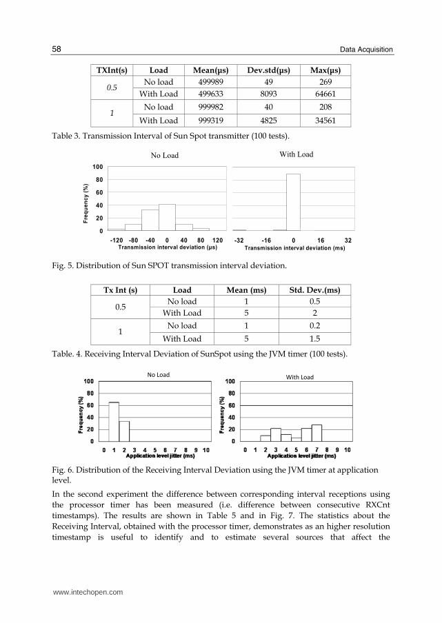
• TXCnt: The value the processor counter TC as “captured” when a frame is transmitted. As first test, the repeatability of the transmission interval of synchronization frame has been
analyzed. Several tests have been made, changing the transmission interval (“TXInt”) and
with different application load. Table 3 shows the measures on transmission interval, i.e. the
difference between two consecutive TXCnt timestamps. As expected, the application load
heavily affects the behaviour of the system apart from the nominal transmission interval; the
standard deviation in both cases increases of an order of magnitude. Fig. 5 compares the
distribution of transmission interval jitter (50 samples, nominal transmission interval of 1 s)
with and without application load. A huge application load (software operation on objects)
delays the transmission of several ms, because of the Garbage Collector operation, though
this affects less than 10% of the test frames. The synchronization algorithms usually use the
receiving time of a synch message sent by a clock master in order to update the local clock.
In the experimental setup the clocks of the Rx nodes have no relation and for this reason the
timestamps related to the same receiving frame cannot be directly compared.
In order to evaluate the jitter between the reception timestamps of the two receivers at
application level, the difference between the corresponding interval reception (i.e. difference
between consecutive RXApp timestamps) has been measured. The test has been made with
different transmission intervals (“TxInt”) and in several load conditions (with or without
operation on objects). Table 4 reports the results. The resolution of RXApp timestamp is only
1 ms, but in any case the application load heavily affects the timestamp accuracy. The Fig. 6
highlights the effect of the load on the distribution of the jitter of receiving interval. For this
reason, the accuracy obtained from a synchronization algorithm that uses RXApp
timestamp should be on the order of some ms.
www.intechopen.com
Data Acquisition
58
TXInt(s) Load Mean(μs) Dev.std(μs) Max(μs)
No load 499989 49 269 0.5
With Load 499633 8093 64661
No load 999982 40 208 1
With Load 999319 4825 34561
Table 3. Transmission Interval of Sun Spot transmitter (100 tests).
With Load No Load
0
20
40
60
80
100
-32 -16 0 16 32Transmission interval deviation (ms)
Fre
qu
en
cy
(%
)
0
20
40
60
80
100
-120 -80 -40 0 40 80 120Transmission interval deviation (μs)
Fre
qu
en
cy
(%
)
Fig. 5. Distribution of Sun SPOT transmission interval deviation.
Tx Int (s) Load Mean (ms) Std. Dev.(ms)
No load 1 0.5 0.5
With Load 5 2
No load 1 0.2 1
With Load 5 1.5
Table. 4. Receiving Interval Deviation of SunSpot using the JVM timer (100 tests).
No LoadWith Load
Fig. 6. Distribution of the Receiving Interval Deviation using the JVM timer at application level.
In the second experiment the difference between corresponding interval receptions using
the processor timer has been measured (i.e. difference between consecutive RXCnt
timestamps). The results are shown in Table 5 and in Fig. 7. The statistics about the
Receiving Interval, obtained with the processor timer, demonstrates as an higher resolution
timestamp is useful to identify and to estimate several sources that affect the
www.intechopen.com

Clock Synchronization of Distributed, Real-Time, Industrial Data Acquisition Systems
59
synchronization. The mean value is mainly due to the frequency drift of the respective
board oscillators; it increases with the increasing of the transmission interval (“Tx Int”)
during the different tests. This parameters usually is estimated and compensated by a
synchronization algorithms. On the other side the standard deviation, mainly due to the
jitter of the SFD signal, cannot be compensated.
In conclusion, the microcontroller timers have to be used in order to improve the synchronization accuracy which is otherwise affected by the SunSPOT system architecture. Using the SFD signal provided by the 802.15.4 transceiver to catch the timer value during the transmission and reception of a frame can improve the overall performance. The timestamp resolution is less than 1 ┤s (below the jitter of the transceiver) and the synchronization accuracy that can be obtained is on the order of few ┤s, equal to the best results which are obtained on traditional, low-level programming platforms. This means that the analyzed platform is suitable for Wireless Data-Acquisition Network in industrial applications.
TxInt(s) Load Mean(μs) Std. Dev.(μs) Max(μs)
No load 1.2 0.4 1 0.5
With Load 1.4 0.4 1.6
No load 2.3 0.4 1.6 1
With Load 2.7 0.4 1
Table 5. Receiving Interval Deviation of SunSpot using the processor counter (100 tests).
0
25
50
75
100
1,9 2,4 2,9 3,4Counter level RID (μs)
Fre
qu
en
cy
(%
)
No Load With Load
0
25
50
75
100
1,9 2,4 2,9 3,4Counter level RID (μs)
Fre
qu
en
cy
(%
)
Fig. 7. Distribution of Receiving Interval Deviation (RID) measured at counter level.
7. Conclusions
The chapter presented the basic concepts regarding the clock synchronization of distributed systems, paying a special attention to the applications of data acquisition in the industrial field. Essential notions of time keeping science have been given in order to define the performance metrics necessary for the evaluation of the clock synchronization algorithms. The clock synchronization for distributed data acquisition system has been discussed in details for both wired and wireless implementation. Many synchronization algorithms have been presented and compared. Last, two real case examples of synchronized data acquisition systems for industrial applications have been presented in order to show the applicability and the advantages of clock synchronization. In the wired case, the application
www.intechopen.com
Data Acquisition
60
uses one of the most diffused and accepted protocol for clock synchronization over a packet-switched network: the IEEE1588 protocol. In the wireless case, a new and promising platform for wireless data acquisition networks has been introduced and its clock synchronization performance has been evaluated. The results of both the real cases confirm that the clock synchronization by means of the same network that is used to collect the logged data, can improve the performance and the versatility of a distributed data acquisition system.
8. Acknowledgment
Authors would like to thank Ing. Stefano Rinaldi, PhD, for the useful preliminary discussions.
9. References
Allan D.W. (1987).“Should the Classical Variance Be Used as a Basic Measure in Standards
Metrology?”, IEEE Trans. on Instrumentation and Measurement, Vol. 36, pp. 646-654,
1987
Correll K., Barendt N., Branicky M. (2005) “Design Considerations for Software Only
Implementations of the IEEE 1588 Precision Time Protocol”, in Proc. of Conference
on IEEE-1588 Standard for a Precision Clock Synchronization Protocol for Networked
Measurement and Control System, pp. 1-6, 2005.
De Dominicis C. M., Ferrari P., Flammini A., Rinaldi S., Quarantelli M. (2010a). "Integration
of Existing IEC61850-based SAS within new High-Availability Architectures", 2010
First IEEE International Workshop on Applied Measuremements for Power Systems,
Aachen, Germany, September 22-24, 2010, pp. 12-17.
De Dominicis C. M., Ferrari P., Flammini A., Sisinni E. (2010b). " Wireless Sensors Exploiting
IEEE802.15.4a for Precise Timestamping ", International Symposium on Precision Clock
Synchronization for Measurement, Control and Communication, 2010. ISPCS 2010,
Portsmuth, USA, September 29- October 1, 2010, pp. 48-54. Best Paper Award
Depari A., Ferrari P., Flammini A., Marioli D., Taroni A.(2008). "A New Instrument for Real-
Time Ethernet Performance Measurement", IEEE Trans. Instrumentation and
Measurement, January, 2008, Vol. 57, N. 1, pp. 121-127.
Eidson J.C., Lee K. (2003). “Sharing a common sense of time”, Instrumentation & Measurement
Magazine, IEEE, Volume 6, Issue 1, March 2003 Pages: 26 - 32
Elson J., Girod L., Estrin D. (2002). “Fine-grained network time synchronization using
reference broadcasts”. In Proc. of Fifth Symposium on Operating Systems Design and
Implementation (OSDI 2002), December 2002.
Felser M. (2005). “Real-Time Ethernet - Industry Prospective”, in Proc. of IEEE, Volume: 93,
Issue: 6, 2005, pp. 1118-1129
Ferrari P., Flammini A., Marioli D., Taroni A. (2008a). "IEEE 1588-Based Synchronization
System for a Displacement Sensor Network", IEEE Trans. Instrumentation and
Measurement, February, 2008, Vol. 57, N. 2, pp. 254-260.
www.intechopen.com

Clock Synchronization of Distributed, Real-Time, Industrial Data Acquisition Systems
61
Ferrari P., Flammini A., Marioli D., Taroni A. (2008b). "A Distributed Instrument for
Performance Analysis of Real-Time Ethernet Networks", IEEE Transactions on
Industrial Informatics, Vol. 4, No. 1, 2008, pp. 16-25.
Flammini A., Rinaldi S., Casalegno F., Telhan O. (2010). "Improving performance of a Java-
based platform for Wireless Sensor Network applications", 2010 IEEE
Instrumentation and Measurement Technology Conference (I2MTC), Austin, TX, USA,
May 3-6, 2010, pp. 1618-1623.
Ganeriwal S., Kumar R., Srivastava M. B. (2003). “Timing-sync protocol for sensor
networks”. In Proc. Of First ACM Conference on Embedded Networked Sensor Systems
(SenSys), November 2003.
Giorgi G., Narduzzi C. (2009). “Performance analysis of Kalman filter-based clock
synchronization in IEEE 1588 networks”, in Proc. of IEEE Int. Symposium on Precision Clock Synchronization for Measurement, Control and Communication
(ISPCS09), Brescia, Italy, pp. 6-12 Oct. 2009.
Hackmand C., Sullivan D. B. (1996). “Time and Frequency Measurement”, American
Association of Physics Teachers, 1996.
Howe D. (1995). “An Extension of the Allan Variance with Increased Confidence at Long
Term”, in Proc. 1995 IEEE international Frequency Control Symposium, USA, pp. 321-
329, 1995.
IEC 61158 family Ed. 2 (2007). “Industrial Communication Networks - Fieldbus
specification”, IEC, 2007.
IEC 61784-2 Ed. 1. (2007). “Industrial communication networks - Profiles - Part 2: Additional
fieldbus profiles for real-time networks based on ISO/IEC 8802-3”, IEC, 2007.
IEEE std.1588. (2002). “Standard for a precision clock synchronization protocol for
networked measurement and control system”, IEEE, 2002.
IEEE std.1588. (2008), “Standard for a Precision Clock Synchronization Protocol for
Networked Measurement and Control Systems”, IEEE, Mar 2008.
IETF RFC 1305 (1992) “Network Time Protocol, Specification, Implementation and Analysis
”, IETF, 1992.
Li C. McKerrow P.J., Lu Q., (2008). “Developing Real-time Applications with Java Based Sun
SPOT”, in proc. of the 2008 Australasian Conference on Robotics & Automation,
Canberra, 3-5 December 2008.
Marzullo K.A., Owicki S. (1983). “Maintaining the time in a distributed system”. In Proc. Of
Second annual ACM symposium on Principles of distributed computing, pp 295–305.
ACM Press, 1983.
Marzullo K.A. (1984). “Maintaining the Time in a Distributed System: An Example of a
Loosely-Coupled Distributed Service”. Ph.D. dissertation, Stanford University,
Department of Electrical Engineering, Feb. 1984.
Proft C. (2007). “The power of LXI instrumentation — use cases and performances”,
Autotestcon 2007, pp.482-489, 2007.
Römer K. (2001).” Time synchronization in ad hoc networks”. In Proc. of ACM Symposium on
Mobile Ad-Hoc Networking and Computing, October 2001.
Su W, Akyildiz I. F. (2005). “Time-diffusion synchronization protocol for sensor networks”.
IEEE/ACM Transactions on Networking, Vol. 13 , Issue 2, pp. 384–397, April 2005.
www.intechopen.com

Data Acquisition
62
Sullivan D.B., Allan D.W., Howe D., and Walls F.L. (1990). “Characterization of Clocks and
Oscillators”, NIST Tech Note 1337, 1990.
Ueda K., Yakoh T. (2004). “Development of time division switching hub for synchronous
TDMA”, IEEE WFCS2004 International Workshop on Factory Communication Systems,
Sept. 2004, pp. 45 – 50
www.intechopen.com
Data AcquisitionEdited by Michele Vadursi
ISBN 978-953-307-193-0Hard cover, 344 pagesPublisher SciyoPublished online 28, September, 2010Published in print edition September, 2010
InTech EuropeUniversity Campus STeP Ri Slavka Krautzeka 83/A 51000 Rijeka, Croatia Phone: +385 (51) 770 447 Fax: +385 (51) 686 166www.intechopen.com
InTech ChinaUnit 405, Office Block, Hotel Equatorial Shanghai No.65, Yan An Road (West), Shanghai, 200040, China
Phone: +86-21-62489820 Fax: +86-21-62489821
The book is intended to be a collection of contributions providing a bird’s eye view of some relevantmultidisciplinary applications of data acquisition. While assuming that the reader is familiar with the basics ofsampling theory and analog-to-digital conversion, the attention is focused on applied research and industrialapplications of data acquisition. Even in the few cases when theoretical issues are investigated, the goal ismaking the theory comprehensible to a wide, application- oriented, audience.
How to referenceIn order to correctly reference this scholarly work, feel free to copy and paste the following:
Alessandra Flammini and Paolo Ferrari (2010). Clock Synchronization of Distributed, Real-Time, IndustrialData Acquisition Systems, Data Acquisition, Michele Vadursi (Ed.), ISBN: 978-953-307-193-0, InTech,Available from: http://www.intechopen.com/books/data-acquisition/clock-synchronization-of-distributed-real-time-industrial-data-acquisition-systems

© 2010 The Author(s). Licensee IntechOpen. This chapter is distributedunder the terms of the Creative Commons Attribution-NonCommercial-ShareAlike-3.0 License, which permits use, distribution and reproduction fornon-commercial purposes, provided the original is properly cited andderivative works building on this content are distributed under the samelicense.