closed-loop/geothermai heat pump · pdf fileclosed-loop/geothermai heat pump systems ......
TRANSCRIPT

Closed-Loop/GeothermaI Heat Pump Systems
Design and Installation Standards
Edited By Phil Albertson, P. E.
Published By lNTERNATIONAL GROUND SOURCE HEAT PUMP ASSOCIATION 490 Cordell South Oklahoma State University Stillwater, OK 74078-8018

Closed-Loop Ground Heat Exchangers - 1
Closed-Loop Ground Heat Exchangers
lA. INSTAUATION PERSONNEL AND TRAINING REQUIRED
1A.1 The loop contractor, or contractor designate, must have a current IGSHPA certification, having completed an lGSHPA training course in the fundamentals of design, installation, and operation of geothermal systems, and having passed the IGSHPA certification examination and pipe fusion tests.
1A.2 Ground heat exchanger fabricators musk have completed a heat fusion school in which each participant has performed heat fusion procedures under direct supervision of an IGSHPA-certif ied heat fusion technician. The fusion techmcian must be thoroughly familiar with heat fusion procedures, and have had formal training and testing at a heat fusion school under direct supervision of an IGSHPA-certified instructor.
1A.2.1 Certified pipe fusion technicians must attend a retraining school every three years. A single failure of a fusion joint will void the certification, and the technician must be retested to demonstrate satisfactory performance.
1A.3 Local and state laws and ordinances as they pertain to buried pipe systems shall be strictly followed or a variance obtained.
1B. DESIGN M m D S AND COMPLIANCE
lB.l The manufacturer's design procedure must foIlow a recognized methodology as presented in the most recent editions of:
a. Closed-Loop/Grotuzd-Source Heat Pump Systems: Installation Guide, IGSHPA FubIications, Oklahoma State University;
b. Data Design Manualfor Closed-Loop/Gro~md-Soirrce Hrat Pump Systems, ASHRAE;
c. IGSHPA's Slinky installation Guide.
1B.2 The ground heat exchanger design must be clearly documented in order to determine compliance with the heat pump manufacturer's and/or utility's specifications.
2 - Closed-Loop Ground Heat Exchangers
1B.3 Soil thermal values shall be used in caIculating loop length, using soil tests as needed. !k the IGSHPA Soil ~ n d Rock CIoss@cario~l Manual, and Soil Conservation Service surveys for count y/parish data which can be obtained from the local SCS office.
1C. GROUND HEAT DCHANCER MATERIALS
1C.I The acceptable pipe and fittings materiais for the underground portion of the ground heat exchanger is polyethylene, as specified in M i o n IC.2.
1C2 Specifications for the polyethylene heat exchanger are as follows:
General. AII pipe and heat- fused materials shall be manufactured from a virgin polyethylene e x m i o n compound material in accordance with ASTM D-2513, Sections 4.1 and 4.2. Pipe shall be manufactured to outside diameters, wall thickness, and respective tolerances as specified in ASTM D-3035, or 112447. Fittings shall be manufactured to diameters, wall thicknes, and respective tolerances as specified in ASRvi D-2683 for socket fittings and ASrU F-1055 for electrofusion fittings.
1C.2.2 Material. The material shall maintain a 2600 psi (110.316 bar) Hydrostatic Design Basis at 73.4.F (23.5.C) per ASTM D-2837, and shall be listed in PPI TR4 as a PEN08 piping formula tion. The material shall be a high density e x h i o n compound having a cell classification of PE345434, PE35543-4, or PE345534 with a W stab-r of C, D, or E as specified in ASTM D-3350 with the following exception: this material shall exhibit zero failures (M) when tested for a minimum of 292 hours under ASTM D- 1693, condition C, as required in ASTM D-3350.
1 C . U Dimensions
1C.2.3.1 Pipewithadiameteroflessthan1~~"(3.175cm)(nominaI) shall be manufactured in accordance with ASTM D-3035 with a minimum (based on pressure rating) dimension ratio of 11.
1C.UJ Pipe manufactured with a diameter of 1V4 " (3.175 cm) (nominal) and Iarger shall be manufactured in accordance with ASTM D-3035 (minimum based on pressure rating] dimension ratio of 15.5) or ASTM D-2447 (Schedule 40). If the pipe is used in a vertical bore application it shall be manufactured in accordance with ASrU D-3035 with a minimum (based on pfessure rating) dimension ratio of 11.
Closed-Loop Ground Heat Exchangers - 3
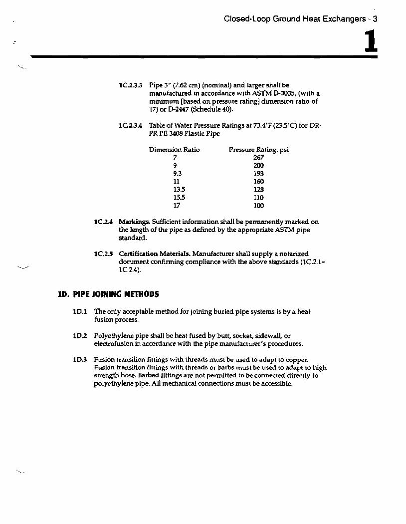
1C.2.33 Pipe 3" (7.62 cm) (nominal) and larger shall be manufactured in accordance with ASTM D-3035, (with a minimum [based on pressure rating] dimension ratio of 17) or D-2447 (Schedule 40).
1C13.4 Table of Water Pressure Ratings at 73.4'F (23.5'C) for DR- PR PE 3408 Plastic Pipe
Dimension Ratio 7 9 9.3 11 13.5 15.5 17
Pressure Rating, psi 267 200 193 160 128 110 100
1C.24 Markings. Sufficient information &ail be permanently marked on the length of the pipe as defined by the appropriate ASTM pipe standard.
1C.2.5 Certification Materials. Manufacturer shall supply a notarized document confirming compliance with the above standards (lC.2.1- 1C.2.4).
ID. PIPE IOIHINC MmODS
1 D.1 The only acceptable method for joining buried pipe systems is by a heat fusion process.
l D 2 Polyethylene pipe shall be heat fused by butt, socket, sidewall, or electrofusion in accordance with the pipe manufacmr 's pnxedures.
1D.3 Fusion transition fittings with threads must be used to adapt to copper. Fusion bansition fittings with threads or barbs must be used to adapt to high strength hose. Barbed fittings are not permitted to be connected directly to polyethylene pipe. All mechanical co~ections must be accessible.
4 - Closed-loop Ground Heat Exchangers
1E. FLUSHING, PURGING, PRESSURE AND FLOW TESTING
1E.3 All fusion joints and loop lengths shall be checked to verify that no leaks have occurred due to fusion joining or shipping damage.
IE.2 All loops will be pressure tested before installation, and all horizontal components of the ground heat exchanger will be pressure tested prior to backfilling.
1E.3 Heat exchangers will be tested hydrostatically at the smaller of 150% of the pipe design or 300"!0 of the system operating pressure.
1E4 No leaks shall occur within a Dminute period,
1E.S Flow rates and pressure drops will be compared to c a l d a t d values to assure that there is no blockage or kinking of any pipe.
1E.6 A minimum velocity of 2 ft /sec (-60% rn/sec) in each piping section must be maintain4 for a minimum of 15 minutes to remove aU air. A change of more than one inch (2.54 cm) in the level of fluid in the purge pump tank during pressurization indicates air still trapped in the system.

Pipe Placement and Backfilling - 5
Pipe Placement and Backfilling
2A. HORiZONTAL PIPING SYSTEMS
2A.1 Sharp bending of pipe around trench comers must be prevented by using a shovel to round comers. Manufacturer's procedures must be followed.
2A.2 Backfilhg procedure will include prevention of any sharp-edged rocks from coming into contact with the pipe by removal of the rmks before backfilling. Use Ihe IGSHPA Slinky backfilling procedures found in IGSHPA8s Slinky 11lstaIlation Gutde to assure elimination of air pockets around the pipes.
ZA.3 Return bends in narrow trenches must be partially backfilled by hand to properly support the pipes and prevent kinking.
2A.4 All buried GHP pipes in systems containing an antifreeze and passing parallel within 5 feet (1.524 m) of any wall, structure, or water pipe shall be insuIa ted with R 2 minimum closed cell insulation.
28. BOREHOLES
2B.1 Vertical boreholes must be backfilled to ensure good heat transfer. Local and state codes concerning backfiIIing requiremenk must be followed. See the IGSHPA Grouting Procedures Manual for detailed grouting procedures.
28.2 Horizontal boreholes must have water (and bentonite if used for drilling) injected into the cuttings left in the hoies as each drill pipe is pulled out, to keep the hole full so that air pockets cannot be pulled in with the U-bend loop as it is pulled in. An alternative is to enlarge the opening of the exit hole and keep it full of a water-bentonite slurry.
2C. POND AND LAWE LOOP SYSTEMS
2C.2 The GHP manufacturer's procedures must be followed.

lndoor Piping and Circulation System - 7
Indoor Piping and Circulation System
3A. CIRCULATOR SIZING AND SYSTEM AND COMPONENTS
3A.1 The circulator wattage for closed Ioop systems must not exceed 150 watts/ ton.
3A.2 Propersizing of thecirrulalingpump will be within theheatpump manufacturer's required flow rate range for the specified unit.
3A.3 Particulate contaminants must be removed from the piping system prior to initial statt-up.
3A.4 Start-up pressurization of the circuit to a minimum of 20 to 30 psi (1.38-2.07 bar) when installed in the summer with circulating water temperature of 70- 90'F (2G30'C) and 40 to 50 psi (2.76-3.45 bar) when installed in the winter with circulating water temperature of 40-50'F (510mC) is required. Standing column designs of circulating systems that ensure a flood4 volute and meet the manufacturer's requirements are excluded.
3A.5 The circulation system must incorporate provisions for flow md temperature-sensing capability for testing the performance of the water side of the heat pump system. Pressure and temperature-sensing ports must be within two (2) feet 66096 m) of the heat pump.
3A.6 Loop charpg valve handles must be removed and/or the ports sufficiently plugged to prevent accidental discharge of system fluid and pressure.
3A.7 Boiler-type service valves are not to be used.
3A.8 Transition fittings between dissimilar material must be inside or accessible.
3A.9 All indoor piping must be insulated where condensate may cause damage.
3A.10 Above-ground piping subject to condensation or freezing shall be insulated.
3A.13 All pipes passing though walls shall be sleeved and sealed with non- hardening caulking material.

8 - Indoor Piping and Circulation System
3A.32 Good quality threaded fittings and a thread sealant specified for use with the antifreeze selected shall be used. Some antifreeze soiutions require more fittings torque than others to prevent leaks and corrosion of external surfaces when the antifreeze is exposed to oxygen.
3B. ANTIFREEZE SELECTION AND USE
38.1 Antifree- solutions must meet lmal and state requirements and b? acceptable by component manufacturers.
38.2 All GHP systems must be labeled and identified at the loop charging valves. The labels must be of a permanent type with the following information:
a. Antifreeze type and concentration; b. Service date; c. Company name; d. Company phone number and responsible party or person.
3C. ANT1FREDE STANDARDS FOR CHP SYST€MS
3C.1 Scope
3C.1.1 Farm. These standards are intended to cover corrosion-inhibited, biodegradable, liquid antifreeze materials as received at the job site.
3C.I.Z Application. For use in closed-loop geothermal heat pump systems for the transfer of energy to provide heating and cooling in residential and commercial applications.
3C.1.3 Safety. While these standards attempt to define antifreeze materials characteristics that are safe to environment and pemnnel, it is the sole responsibility of the user to become familiar with the safe and proper use of materials provided under these standards and to take necessary precautionary measures to insufe the health and safety of all personnel involved.
3C2 Technical Requirements
3C.2.1 Material. The composition of the fluid shall be at the option of the manufacturer. The fluid may contain corrosion inhibitors, etc., as required to produce a product meeting the requirements of 2.2.
3C.2.1.1 Biodegradability. The fluid shall not be less than 90%, biodegradable. Results of biodegradability studies conducted in accordance with "Stnndflrd MrthndsJnr IIW

Indoor Piping and Circulation System - 9
Exlinrimtiort of Wmr arrd Wirstr Wnrrr," for biodegradability and bioassay shall, when requested by purchaser, be provided by the fluid manufacturer to purchaser and shall contain not less than the foliowing informatwn:
a. A statement of ecological behavior of the fluid; b. The total oxygen demand (TOD) of the fluid,
expressed in pounds of oxygen per pound of fluid; c. The percent of the fluid degraded in five days.
3C.21.2 Corrosion. The fluid shall demonstrate low corrosion to internal surface of all materials commonly found in geothermal heat pump sy;tems.
3C.2.2 Properties. The fluid shall conform to the following requirements, and tests shall be performed in accordance with specified test methds on the fluid:
3C22.1 Flash Point. Shall not be lower than 194'F (90'C), determined in accordance with ASlhi D-92.
3C-22.2 8iotogicalOxygenDemmd. FivedaysBODat 10'C(509F) shall not exceed 0.2 gram oxygen per gram nor be less than 0.1 gram oxygen per gram.
3C.22.3 Freezing Point. Shall not exceed +18'F (-VC), determined in accordance with ASTM D-1177.
3C.2.2.4 Toxicity. ShaIl not be less than LD 50 (oral-rats) of 5 grams per kilogram, The NFPA hazardous material rating for health shalI not be more than 1 (slight).
3C.22.5 Storage Stability, The fluid, tested in accordance with ASTM F-1105, shall show neither separation from exposure to heat or cold, nor show an increase in turbidity.
3C.23 Quality. The fluid, as received by purchaser, shall be homogeneous, uniform in color, and free from skins, lumps, and foreign materials detrimental to usage of the fluid.
3C.3 Packaging and Identification
3C5.1 Fluid shall be packaged in containers of a type and siw agreed upon by purchaser and vendor, or shall be delivered in bulk, as ordered.

10 - Indoor Piping and Circulation System
3C.3.2 Containers of fluid shall be prepared for shipment in accordance with commercjal practice and in compliance with applicable rules and regulations pertaining to the handling, packaging, and transportation of the fluid to ensure carrier acceptance and safe delivery.
3C3.3 An u p i d a t e Material Safety Data Sheet shall be supplied to each purchaser on request and concurrent with each deIivery.

Ground Source Heat Pumps - 1 1
Geothermal Heat Pumps
4A. GEOTHERMAL HEAT PUMPS
4A.1 Water source heat pumps used in conjunction with ground heat exchangers must be appropriately ARI certified and listed for the minimum design water temperatures.
4A2 The maximum and minimum design-entering water temperatures shall not e x e d the manufacturer's published data.
4A.3 The heat pump air flow must be within the manufacturer's specifications.
Site Planning, Records, and Restoration - 13
Site Planning, Records, and Restoration 5 SA. PLANNING
SA.l Prior to any excavation, trenching, or drilling, all buried utilities, drainage, and irrigation systems shall be located and flagged by the appropriate utility and contractor representatives.
56. RECORDS
5B.1 The contractor shall provide the owner with a copy of a dimensioned site layout showing the location of the buried GHP piping relative to a permanent structure and buried conduits.
58.2 The contractor shall make available, on request, a certificate describing the specifications and the start-up performance test results of the system.
5B.3 Any loop registration program shall conform to IGSHPA specifications.
5C. RESTORATION
5C.1 Prior to any excavation, trenching, or drilling, the contractor and owner shall agree in writing to site restoration requirements and whether to instaIL metallizwl warning tape above the buried pipe system.